WO2019159264A1 - 電力変換システム、昇降システム及び電力変換方法 - Google Patents
電力変換システム、昇降システム及び電力変換方法 Download PDFInfo
- Publication number
- WO2019159264A1 WO2019159264A1 PCT/JP2018/005114 JP2018005114W WO2019159264A1 WO 2019159264 A1 WO2019159264 A1 WO 2019159264A1 JP 2018005114 W JP2018005114 W JP 2018005114W WO 2019159264 A1 WO2019159264 A1 WO 2019159264A1
- Authority
- WO
- WIPO (PCT)
- Prior art keywords
- power
- state
- conversion
- consumption
- circuit
- Prior art date
- Legal status (The legal status is an assumption and is not a legal conclusion. Google has not performed a legal analysis and makes no representation as to the accuracy of the status listed.)
- Ceased
Links
Images






Classifications
-
- B—PERFORMING OPERATIONS; TRANSPORTING
- B66—HOISTING; LIFTING; HAULING
- B66B—ELEVATORS; ESCALATORS OR MOVING WALKWAYS
- B66B5/00—Applications of checking, fault-correcting, or safety devices in elevators
- B66B5/02—Applications of checking, fault-correcting, or safety devices in elevators responsive to abnormal operating conditions
-
- H—ELECTRICITY
- H02—GENERATION; CONVERSION OR DISTRIBUTION OF ELECTRIC POWER
- H02J—ELECTRIC POWER NETWORKS; CIRCUIT ARRANGEMENTS OR SYSTEMS FOR SUPPLYING OR DISTRIBUTING ELECTRIC POWER; SYSTEMS FOR STORING ELECTRIC ENERGY
- H02J9/00—Circuit arrangements for emergency or stand-by power supply, e.g. for emergency lighting
- H02J9/04—Circuit arrangements for emergency or stand-by power supply, e.g. for emergency lighting in which the distribution system is disconnected from the normal source and connected to a standby source
- H02J9/06—Circuit arrangements for emergency or stand-by power supply, e.g. for emergency lighting in which the distribution system is disconnected from the normal source and connected to a standby source with automatic change-over, e.g. UPS systems
-
- H—ELECTRICITY
- H02—GENERATION; CONVERSION OR DISTRIBUTION OF ELECTRIC POWER
- H02M—APPARATUS FOR CONVERSION BETWEEN AC AND AC, BETWEEN AC AND DC, OR BETWEEN DC AND DC, AND FOR USE WITH MAINS OR SIMILAR POWER SUPPLY SYSTEMS; CONVERSION OF DC OR AC INPUT POWER INTO SURGE OUTPUT POWER; CONTROL OR REGULATION THEREOF
- H02M5/00—Conversion of AC power input into AC power output, e.g. for change of voltage, for change of frequency, for change of number of phases
- H02M5/02—Conversion of AC power input into AC power output, e.g. for change of voltage, for change of frequency, for change of number of phases without intermediate conversion into DC
- H02M5/04—Conversion of AC power input into AC power output, e.g. for change of voltage, for change of frequency, for change of number of phases without intermediate conversion into DC by static converters
- H02M5/22—Conversion of AC power input into AC power output, e.g. for change of voltage, for change of frequency, for change of number of phases without intermediate conversion into DC by static converters using discharge tubes with control electrode or semiconductor devices with control electrode
- H02M5/275—Conversion of AC power input into AC power output, e.g. for change of voltage, for change of frequency, for change of number of phases without intermediate conversion into DC by static converters using discharge tubes with control electrode or semiconductor devices with control electrode using devices of a triode or transistor type requiring continuous application of a control signal
- H02M5/293—Conversion of AC power input into AC power output, e.g. for change of voltage, for change of frequency, for change of number of phases without intermediate conversion into DC by static converters using discharge tubes with control electrode or semiconductor devices with control electrode using devices of a triode or transistor type requiring continuous application of a control signal using semiconductor devices only
-
- H—ELECTRICITY
- H02—GENERATION; CONVERSION OR DISTRIBUTION OF ELECTRIC POWER
- H02M—APPARATUS FOR CONVERSION BETWEEN AC AND AC, BETWEEN AC AND DC, OR BETWEEN DC AND DC, AND FOR USE WITH MAINS OR SIMILAR POWER SUPPLY SYSTEMS; CONVERSION OF DC OR AC INPUT POWER INTO SURGE OUTPUT POWER; CONTROL OR REGULATION THEREOF
- H02M5/00—Conversion of AC power input into AC power output, e.g. for change of voltage, for change of frequency, for change of number of phases
- H02M5/02—Conversion of AC power input into AC power output, e.g. for change of voltage, for change of frequency, for change of number of phases without intermediate conversion into DC
- H02M5/04—Conversion of AC power input into AC power output, e.g. for change of voltage, for change of frequency, for change of number of phases without intermediate conversion into DC by static converters
- H02M5/22—Conversion of AC power input into AC power output, e.g. for change of voltage, for change of frequency, for change of number of phases without intermediate conversion into DC by static converters using discharge tubes with control electrode or semiconductor devices with control electrode
- H02M5/275—Conversion of AC power input into AC power output, e.g. for change of voltage, for change of frequency, for change of number of phases without intermediate conversion into DC by static converters using discharge tubes with control electrode or semiconductor devices with control electrode using devices of a triode or transistor type requiring continuous application of a control signal
- H02M5/297—Conversion of AC power input into AC power output, e.g. for change of voltage, for change of frequency, for change of number of phases without intermediate conversion into DC by static converters using discharge tubes with control electrode or semiconductor devices with control electrode using devices of a triode or transistor type requiring continuous application of a control signal for conversion of frequency
Definitions
- the present disclosure relates to a power conversion system, a lifting system, and a power conversion method.
- Patent Document 1 discloses a system including a PWM cycloconverter device having a bidirectional switch module and a power switch.
- the power supply switcher switches between a state in which the three-phase output from the three-phase AC power source is output to the bidirectional switch module and a state in which the voltage of the storage battery is output to the bidirectional switch module.
- This disclosure is intended to provide a matrix converter type power conversion system that can easily secure an emergency power supply.
- a power conversion system includes a matrix converter circuit, and a power conversion unit that performs bidirectional power conversion between primary AC power and secondary AC power using the matrix converter circuit; A power supply switching unit that switches between a normal state in which the first AC power supply is connected to the primary side of the power conversion unit and an emergency state in which the emergency second AC power supply is connected to the primary side of the power conversion unit; A power consumption unit connected between the AC power source and the power conversion unit and consuming regenerative power from the secondary side to the primary side.
- a lifting system includes a matrix converter circuit, and a power converter that performs bidirectional power conversion between the primary AC power and the secondary AC power using the matrix converter circuit;
- a power supply switching unit that switches between a normal state in which the first AC power supply is connected to the primary side of the power conversion unit and an emergency state in which the emergency second AC power supply is connected to the primary side of the power conversion unit;
- Connected between the AC power source and the power converter a power consuming unit that consumes regenerative power from the secondary side to the primary side, an electric motor connected to the secondary side of the power converter, and ascending and descending by the power of the motor A lifting body.
- a power conversion method includes a matrix converter circuit, and performs power conversion bidirectionally between primary-side AC power and secondary-side AC power using the matrix converter circuit. Controlling the power supply switching unit to switch between a normal state in which the first AC power source is connected to the primary side of the unit and an emergency state in which the emergency second AC power source is connected to the primary side of the power conversion unit; And controlling the power consumption unit to consume regenerative power from the secondary side to the primary side in an emergency state.
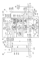
- Elevating System 1 shown in FIG. 1 is an elevator system, for example, an elevating body 12, a hoisting machine 13, a weight 14, a wire rope 15, a brake 17, and power conversion. System 20.
- the wire rope 15 is hung on the hoisting machine 13 so that both ends of the wire rope 15 hang downward.
- the elevating body 12 is a car on which the user is boarded, and is connected to one end of the wire rope 15.
- the weight 14 is a counterweight for causing the wire rope 15 to generate a tension against the weight of the elevating body 12 via the wire rope 15.
- the hoisting machine 13 rotates to change the ratio of the length of the wire rope 15 that hangs down to the lifting body 12 side and the length of the wire rope 15 that hangs down to the weight 14 side.
- the driving device 11 rotates the hoisting machine 13 using the motor 16 (electric motor) as a power source, and moves the elevating body 12 up and down. That is, the lifting body 12 is lifted and lowered by the power of the motor 16.
- the brake 17 applies a braking force to the elevating body 12.
- Specific examples of the brake 17 include a mechanical brake such as a disc brake that applies a braking force to the hoisting machine 13.
- the power conversion system 20 is interposed between the power source and the motor 16, converts the power from the power source into driving AC power, and outputs it to the motor 16.
- the power conversion system 20 includes a power conversion unit 30, a power supply switching unit 40, a power consumption unit 50, a brake driver 60, and a power management device 300.
- the power conversion unit 30 includes a matrix converter circuit, and performs bidirectional power conversion between the primary side (power supply side) AC power and the secondary side (motor 16 side) AC power by the matrix converter circuit.
- Bidirectional power conversion means that both power conversion that transmits AC power from the primary side to the secondary side and power conversion that transmits AC power (for example, regenerative power) from the secondary side to the primary side can be performed.
- the primary side of the power conversion unit 30 is connected to the first AC power source or an emergency power source different from the first AC power source.
- the motor 16 is connected to the secondary side of the power conversion unit 30. Therefore, the power conversion unit 30 performs bidirectional power conversion between the first AC power supply or emergency power supply and the motor 16.
- the power switching unit 40 has a state in which the first AC power source is connected to the primary side of the power conversion unit 30 (hereinafter referred to as “normal state”) and an emergency power source (for example, the second AC power source).
- the state connected to the primary side (hereinafter referred to as “emergency state”) is switched.
- the first AC power source is, for example, a three-phase AC power system 2.
- the second AC power supply is, for example, a three-phase AC uninterruptible power supply 3.
- the power consumption unit 50 is connected between the second AC power source and the power conversion unit 30 and consumes regenerative power (for example, regenerative power from the motor 16) from the secondary side to the primary side of the power conversion unit 30.
- the brake driver 60 supplies the brake 17 with electric power for switching between an operating state in which a braking force is applied to the lifting body 12 and a release state in which the braking force on the lifting body 12 is released.
- the power management device 300 controls the power switching unit 40 to switch between the normal state and the emergency state according to the state of the power system 2 (for example, the occurrence state of a power failure), and sends various commands according to the power conversion unit 30 and Output to the brake driver 60.
- the power conversion unit 30 converts the power from the power system 2 or the uninterruptible power supply device 3 into driving AC power and outputs it to the motor 16.
- the uninterruptible power supply 3 converts alternating current power from the power system 2 into direct current and stores it, and converts the stored direct current power into three-phase alternating current in the event of a power outage or the like of the power system 2. Output.
- the primary side of the uninterruptible power supply 3 is connected to the power grid 2 via input lines 24R, 24S, and 24T.
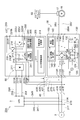
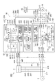
- the power conversion unit 30 includes an AC-AC conversion matrix converter circuit 111, a DC-AC conversion inverter circuit 214, and an output switching unit 31.
- the matrix converter circuit 111 performs bidirectional AC-AC conversion between the power system 2 and the motor 16 (AC type load).
- the inverter circuit 214 performs bidirectional DC-AC conversion between the uninterruptible power supply 3 and the motor 16.
- the matrix converter circuit 111 is connected between the primary side and the secondary side according to the switching between the normal state and the emergency state (that is, the matrix converter circuit 111 is connected to the motor 16).
- the AC-AC conversion state and the DC-AC conversion state in which the inverter circuit 214 is connected between the primary side and the secondary side are switched.
- switching between the AC-AC conversion state and the DC-AC conversion state in accordance with the switching between the normal state and the emergency state means switching between the normal state and the emergency state, the AC-AC conversion state, and the DC-AC conversion. It only means that the state switching is related to each other, and does not define the context between them. That is, the output switching unit 31 may switch between the AC-AC conversion state and the DC-AC conversion state after switching between the normal state and the emergency state, and simultaneously with the switching between the normal state and the emergency state, AC-AC conversion. The state and the DC-AC conversion state may be switched, and the AC-AC conversion state and the DC-AC conversion state may be switched prior to switching between the normal state and the emergency state.
- the power consumption unit 50 includes a rectifier circuit 211, a resistance element 233 for power consumption, and a changeover switch 232 (consumption state switching unit).
- the rectifier circuit 211 converts AC power from the uninterruptible power supply 3 into DC power and outputs the DC power to the power conversion unit 30 side.
- the changeover switch 232 the consumption element is connected between the positive electrode side and the negative electrode side of the DC power generated by the rectifier circuit 211, and the resistor element 233 is not connected between the positive electrode side and the negative electrode side.
- the consumption-off state is switched according to the generation state of regenerative power from the motor 16.
- the power conversion unit 30 and the power consumption unit 50 are configured using a matrix converter device 100 and an inverter device 200 that are unitized as separate units.
- the matrix converter device 100 includes the above-described matrix converter circuit 111, snubber circuit 120, discharge circuit 130, voltage sensor 115, control circuit 140, primary side terminals 113R, 113S, and 113T, and secondary side terminals 114U, 114V, 114W.
- the matrix converter circuit 111 is provided between the primary side terminals 113R, 113S, and 113T and the secondary side terminals 114U, 114V, and 114W, and performs bidirectional power conversion.
- the matrix converter circuit 111 includes a plurality of bidirectional switches 112 arranged in a matrix (for example, nine bidirectional switches 112 arranged in a matrix of 3 rows and 3 columns). Bidirectional power conversion is performed by turning off.
- the bidirectional switch 112 includes two IGBTs (Insulated Gate Bipolar Transistors) connected in parallel so as to be opposite to each other.
- the primary side terminals 113R, 113S, and 113T are connected to the power system 2 via input lines 21R, 21S, and 21T, respectively.
- Secondary terminals 114U, 114V, 114W are connected to motor 16 via output lines 28U, 28V, 28W, respectively.
- the matrix converter circuit 111 performs bidirectional AC-AC conversion between the power system 2 and the motor 16 (AC-type load).
- the snubber circuit 120 stores at least AC power (regenerative power) on the secondary side of the matrix converter circuit 111 as DC.
- the snubber circuit 120 converts both the primary side and secondary side AC power of the matrix converter circuit 111 into a direct current and stores it.
- the snubber circuit 120 includes rectifier circuits 121 and 122 and a capacitor 124.
- the rectifier circuit 121 is, for example, a diode bridge circuit, and converts the alternating current on the primary side of the matrix converter circuit 111 into a direct current and supplies it to the direct current buses 123P and 123N.
- the rectifier circuit 122 is a diode bridge circuit, for example, and converts the secondary side alternating current of the matrix converter circuit 111 into direct current and supplies it to the direct current buses 123P and 123N.
- Capacitor 124 is connected between DC buses 123P and 123N, and stores DC power supplied to DC buses 123P and 123N.
- the discharge circuit 130 is a circuit that discharges the capacitor 124.
- the discharge circuit 130 includes a discharge switch 131 and a resistance element 132.
- the discharge switch 131 and the resistance element 132 are connected in series between the DC buses 123P and 123N.
- the discharge switch 131 is, for example, an IGBT, and switches between an on state in which the resistance element 132 is connected between the DC buses 123P and 123N and an off state in which the resistance element 132 is not connected between the DC buses 123P and 123N.
- the discharge switch 131 When the discharge switch 131 is turned on, the power stored in the capacitor 124 is consumed in the resistance element 132.
- Voltage sensor 115 detects a DC voltage between DC buses 123P and 123N.
- the control circuit 140 converts power between the AC power on the primary side (primary side terminals 113R, 113S, 113T side) and the AC power on the secondary side (secondary side terminals 114U, 114V, 114W side) (AC-AC conversion). ) To control the matrix converter circuit 111. Further, the control circuit 140 determines that the matrix converter circuit 111 has a discharge state in which the resistance element 132 is connected between the DC buses 123P and 123N and a non-discharge state in which the resistance element 132 is not connected between the DC buses 123P and 123N. It switches according to the generation situation of regenerative power from the secondary side.
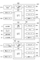
- the control circuit 140 includes an AC-AC conversion control unit 141 and a discharge control unit 142 as a functional configuration (hereinafter referred to as “functional module”).
- the AC-AC conversion control unit 141 controls the matrix converter circuit 111 so as to perform the AC-AC conversion. More specifically, the AC-AC conversion control unit 141 outputs a gate drive signal to the plurality of bidirectional switches 112 of the matrix converter circuit 111 so as to execute desired power conversion.
- the discharge control unit 142 controls the discharge circuit 130 so as to switch between the discharge state and the non-discharge state according to the generation state of the regenerative power.
- the discharge control unit 142 switches the discharge switch 131 on and off according to a DC voltage value between the DC buses 123P and 123N detected by the voltage sensor 115. For example, when the DC voltage value between the DC buses 123P and 123N is below a predetermined threshold value, the discharge control unit 142 keeps the discharge switch 131 in an off state, and the DC voltage value exceeds the threshold value. The discharge switch 131 is turned on.
- the inverter device 200 includes the rectifier circuit 211, the inverter circuit 214, the changeover switch 232, the voltage sensor 215, the control circuit 240, the DC buses 212P and 212N, and the AC terminals 221R, 221S, and 221T. And AC terminals 222U, 222V, 222W, DC terminals 223P, 223N, and braking resistance terminals 231P, 231N.
- the rectifier circuit 211 is a diode bridge circuit, for example, and converts the AC power input to the AC terminals 221R, 221S, and 221T to DC and outputs the DC power to the DC buses 212P and 212N.
- the inverter circuit 214 converts the DC power of the DC buses 212P and 212N into AC power and outputs the AC power to the AC terminals 222U, 222V, and 222W.
- the inverter circuit 214 has a plurality of switches such as IGBTs. By switching on and off the plurality of switches, it is possible to convert DC power into AC power.
- DC terminals 223P and 223N are terminals for inputting DC power instead of AC power, and are connected to the DC side of the inverter circuit 214. Specifically, DC terminals 223P and 223N are connected to DC buses 212P and 212N, respectively. The capacitor 213 is connected between the DC buses 212P and 212N.
- the braking resistance terminals 231P and 231N are terminals for externally attaching a braking resistance or the like.
- the braking resistance terminal 231P is connected to the DC bus 212P, and the braking resistance terminal 231N is connected to the DC bus 212N via the changeover switch 232.
- the changeover switch 232 is, for example, an IGBT, and is in an ON state in which a braking resistor externally connected to the braking resistance terminals 231P and 231N is connected between the DC buses 212P and 212N, and the braking resistor is between the DC buses 212P and 212N. Switch to off state not connected to.
- Voltage sensor 215 detects a DC voltage between DC buses 212P and 212N.
- the AC terminals 221R, 221S, 221T are connected to the secondary side (output side) of the uninterruptible power supply 3 through the emergency input lines 25R, 25S, 25T, respectively.
- the AC terminals 222U, 222V, and 222W are connected to the motor 16 via output lines 29U, 29V, and 29W, respectively.
- the inverter circuit 214 performs bidirectional DC-AC conversion between the uninterruptible power supply 3 and the motor 16.
- a resistance element 233 is connected between the braking resistance terminals 231P and 231N.
- the rectifier circuit 211, the resistance element 233, and the changeover switch 232 constitute the power consuming unit 50.
- the changeover switch 232 is a consumption in which a resistance element 233 is connected between the positive electrode side and the negative electrode side of DC power between the rectifier circuit 211 and the inverter circuit 214 (that is, between the uninterruptible power supply 3 and the inverter circuit 214).
- the on state and the consumption off state in which the resistance element 233 is not connected between the positive electrode side and the negative electrode side are switched according to the generation state of regenerative power.
- the control circuit 240 controls the inverter circuit 214 to perform DC-AC conversion.
- the control circuit 240 sets a consumption on state in which the resistance element 233 is connected between the DC buses 212P and 212N and a consumption off state in which the resistance element 233 is not connected between the DC buses 212P and 212N from the motor 16. Switch according to the generation status of regenerative power.
- the control circuit 240 includes a DC-AC conversion control unit 242 and a consumption control unit 241 as functional modules.
- the DC-AC conversion control unit 242 controls the inverter circuit 214 so as to perform the DC-AC conversion. More specifically, the DC-AC conversion control unit 242 outputs gate drive signals to the plurality of switches of the inverter circuit 214 so as to execute desired power conversion. The DC-AC conversion control unit 242 may control the inverter circuit 214 to gradually increase the output power at the start of the DC-AC conversion state (a state where the inverter circuit 214 is connected to the motor 16).
- the consumption control unit 241 controls the changeover switch 232 so as to switch between the consumption on state and the consumption off state according to the generation state of the regenerative power. For example, the consumption control unit 241 controls the changeover switch 232 to switch the consumption off state to the consumption on state in response to the increase in the regenerative power and to switch the consumption on state to the consumption off state in response to the decrease in the regenerative power. .
- the consumption control unit 241 switches between the consumption on state and the consumption off state based on the DC voltage value between the DC buses 212P and 212N. For example, the consumption control unit 241 maintains the consumption off state when the DC voltage value between the DC buses 212P and 212N is below a predetermined threshold, and sets the consumption off state when the voltage value exceeds the threshold.
- the changeover switch 232 is controlled to switch to the consumption on state.
- the consumption control unit 241 controls the changeover switch 232. At this time, it is not necessarily required to be based on the DC voltage value between the DC buses 212P and 212N.
- the consumption control unit 241 may control the changeover switch 232 to switch between the consumption on state and the consumption off state based on the DC voltage value between the DC buses 123P and 123N of the snubber circuit 120.
- the consumption control unit 241 may control the changeover switch 232 so as to switch between the consumption on state and the consumption off state according to whether or not regenerative power is generated. Whether or not regenerative power is generated can be detected based on, for example, whether the elevating body 12 is rising or falling.
- the output switching unit 31 switches between the AC-AC conversion state (a state where the matrix converter circuit 111 is connected to the motor 16) and the DC-AC conversion state (a state where the inverter circuit 214 is connected to the motor 16).
- the matrix converter device 100, the inverter device 200, and the motor 16 are provided.
- the output switching unit 31 includes changeover switches 32U, 32V, and 32W provided on output lines 28U, 28V, and 28W for connecting the matrix converter device 100 to the motor 16, respectively, and an output line 29U for connecting the inverter device 200 to the motor 16. , 29V, and 29W, respectively, and selector switches 33U, 33V, and 33W.
- the changeover switches 32U, 32V, and 32W are, for example, electromagnetic contactors, and open and close an electric circuit between the matrix converter device 100 and the motor 16.
- the changeover switches 33U, 33V, and 33W are, for example, electromagnetic contactors, and open and close an electric circuit between the inverter device 200 and the motor 16.
- the power switching unit 40 includes the normal state (a state where the power system 2 is connected to the primary side of the power conversion unit 30) and the emergency state (the uninterruptible power supply 3 is connected to the primary side of the power conversion unit 30). State) is provided between the power system 2 and the uninterruptible power supply 3 and the power conversion unit 30.
- the power supply switching unit 40 connects the changeover switches 41R, 41S, and 41T respectively provided on the input lines 21R, 21S, and 21T that connect the matrix converter device 100 to the power system 2, and the inverter device 200 to the uninterruptible power supply device 3.
- Switching switches 42R, 42S, and 42T provided on the emergency input lines 25R, 25S, and 25T, respectively.
- the changeover switches 41R, 41S, and 41T are, for example, electromagnetic contactors, and open and close an electric circuit between the power system 2 and the matrix converter device 100.
- the changeover switches 42R, 42S, and 42T are, for example, electromagnetic contactors, and open and close an electric circuit between the uninterruptible power supply 3 and the inverter device 200.
- the power management apparatus 300 includes an input switching control unit 311, an output switching control unit 312, a parameter transfer unit 313, and a braking state switching unit 314 as functional modules.
- the input switching control unit 311 controls the power supply switching unit 40 so as to switch between the normal state and the emergency state according to the state of the power system 2 (for example, a power failure occurrence state). For example, the input switching control unit 311 outputs an opening / closing command for switching between the normal state and the emergency state to the changeover switches 41R, 41S, 41T and the changeover switches 42R, 42S, 42T.
- the output switching control unit 312 controls the output switching unit 31 to switch between the AC-AC conversion state and the DC-AC conversion state in accordance with the switching between the normal state and the emergency state by the power supply switching unit 40. .
- the output switching control unit 312 outputs an opening / closing command for switching between the AC-AC conversion state and the DC-AC conversion state to the changeover switches 32U, 32V, 32W and the changeover switches 33U, 33V, 33W.
- the output switching control unit 312 is in a state where neither the matrix converter circuit 111 nor the inverter circuit 214 is connected between the primary side and the secondary side (a state where neither the matrix converter circuit 111 nor the inverter circuit 214 is connected to the motor 16). Then, the output switching unit 31 may be controlled to switch between the AC-AC conversion state and the DC-AC conversion state. For example, the output switching control unit 312 determines a state in which neither the matrix converter circuit 111 nor the inverter circuit 214 is connected between the primary side and the secondary side between the AC-AC conversion state and the DC-AC conversion state. The output switching unit 31 may be controlled so as to continue for a period or more. The predetermined period is set so that the return current between the matrix converter device 100 and the inverter device 200 is substantially zero.
- the parameter transfer unit 313 transfers parameters related to the motor 16 from one side of the matrix converter device 100 and the inverter device 200 to the other side.
- parameters related to the motor 16 include inductance, resistance, control gain, and the like of the motor 16.
- the parameter transfer unit 313 transfers the parameters between the AC / AC conversion control unit 141 and the DC / AC conversion control unit 242.
- the braking state switching unit 314 controls the brake driver 60 so as to switch the operating state and the releasing state of the brake 17. For example, the braking state switching unit 314 operates the brake 17 when power is not supplied from the power conversion unit 30 to the motor 16, and releases the brake 17 when power is supplied from the power conversion unit 30 to the motor 16.
- the input switching control unit 311, the output switching control unit 312, the parameter transfer unit 313, and the braking state switching unit 314 are not necessarily provided in the power management device 300.
- the power supply switching unit 40 and the output switching unit 31 are configured to cooperate with each other and autonomously execute switching between a normal state and an emergency state, and switching between an AC-AC conversion state and a DC-AC conversion state. Also good.
- control circuit 140 of the matrix converter device 100 and the control circuit 240 of the inverter device 200 may include a parameter transfer unit.
- brake driver 60 itself may be configured to function as a braking state switching unit in cooperation with the matrix converter device 100 and the inverter device 200.
- the control circuit 140 includes one or a plurality of processors 191, a memory 192, a storage 193, a gate drive circuit 194, an input / output port 195, and a communication port 196.
- the storage 193 includes a computer-readable storage medium such as a hard disk.
- the storage medium stores a program for configuring each functional module of the control circuit 140.
- the storage medium may be a removable medium such as a nonvolatile semiconductor memory, a magnetic disk, and an optical disk.
- the memory 192 temporarily stores the program loaded from the storage medium of the storage 193 and the calculation result by the processor 191.
- the processor 191 configures each functional module of the control circuit 140 by executing the program in cooperation with the memory 192.
- the gate drive circuit 194 outputs a gate drive signal to the matrix converter circuit 111 in accordance with a command from the processor 191.
- the input / output port 195 inputs and outputs electrical signals between the voltage sensor 115 and the discharge switch 131 in accordance with instructions from the processor 191.
- the communication port 196 performs information communication with the power management apparatus 300 in accordance with a command from the processor 191.
- the control circuit 240 includes one or more processors 291, a memory 292, a storage 293, a gate drive circuit 294, an input / output port 295, and a communication port 296.
- the storage 293 includes a computer-readable storage medium such as a hard disk.
- the storage medium stores a program for configuring each functional module of the control circuit 240.
- the storage medium may be a removable medium such as a nonvolatile semiconductor memory, a magnetic disk, and an optical disk.
- the memory 292 temporarily stores the program loaded from the storage medium of the storage 293 and the calculation result by the processor 291.
- the processor 291 configures each functional module of the control circuit 240 by executing the program in cooperation with the memory 292.
- the gate drive circuit 294 outputs a gate drive signal to the inverter circuit 214 in accordance with a command from the processor 291.
- the input / output port 295 inputs and outputs electrical signals between the voltage sensor 215 and the changeover switch 232 in accordance with instructions from the processor 291.
- the communication port 296 performs information communication with the power management apparatus 300 in accordance with a command from the processor 291.
- the power management device 300 is configured by, for example, a programmable logic controller and has a circuit 390.
- the circuit 390 includes one or more processors 391, a memory 392, a storage 393, a power failure sensor 394, an input / output port 395, and a communication port 396.
- the storage 393 includes a computer-readable storage medium such as a hard disk.
- the storage medium stores a program for configuring each functional module of the power management device 300.
- the storage medium may be a removable medium such as a nonvolatile semiconductor memory, a magnetic disk, and an optical disk.
- the memory 392 temporarily stores the program loaded from the storage medium of the storage 393 and the calculation result by the processor 391.
- the processor 391 configures each functional module of the power management device 300 by executing the program in cooperation with the memory 392.
- the power failure sensor 394 detects a power failure occurrence state in the power system 2 in accordance with a command from the processor 391.
- the input / output port 395 performs input / output of electrical signals between the brake driver 60, the power supply switching unit 40, and the output switching unit 31 in accordance with instructions from the processor 391.
- the communication port 396 performs information communication with the control circuits 140 and 240 in accordance with a command from the processor 391.
- This procedure controls the power supply switching unit 40 to switch between the normal state and the emergency state, and controls the power consumption unit 50 to consume regenerative power from the secondary side to the primary side in the emergency state. And including.
- the procedure further includes controlling the output switching unit 31 to switch between the AC-AC conversion state and the DC-AC conversion state in accordance with switching between the normal state and the emergency state.
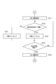
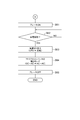
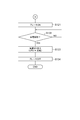
- the power conversion system 20 first executes steps S01, S02, S03, and S04 in order.
- step S01 the input switching control unit 311 waits for the occurrence of a power failure in the power system 2.
- step S02 the braking state switching unit 314 controls the brake driver 60 to switch the brake 17 from the released state to the operating state.
- step S03 the input switching control unit 311 controls the power supply switching unit 40 so as to switch the normal state to the emergency state.
- the output switching control unit 312 controls the output switching unit 31 so that both the matrix converter device 100 and the inverter device 200 are disconnected from the motor 16.
- the output switching control unit 312 disconnects the matrix converter device 100 and the motor 16 by the changeover switches 32U, 32V, and 32W, and disconnects the inverter device 200 and the motor 16 by the changeover switches 33U, 33V, and 33W.
- the output switching unit 31 is controlled.
- step S05 the output switching control unit 312 waits for the predetermined period to elapse.
- step S ⁇ b> 06 the output switching control unit 312 controls the output switching unit 31 so that the matrix converter device 100 is not connected to the motor 16 and the inverter device 200 is connected to the motor 16.
- the output switching control unit 312 connects the inverter device 200 and the motor 16 by the changeover switches 33U, 33V, and 33W in a state where the matrix converter device 100 and the motor 16 are disconnected by the changeover switches 32U, 32V, and 32W.
- the output switching unit 31 is controlled.
- step S07 the braking state switching unit 314 controls the brake driver 60 to switch the brake 17 from the operating state to the released state.
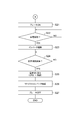
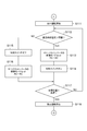
- step S11 the DC-AC conversion control unit 242 controls the inverter circuit 214 so as to start a rescue operation in which the elevator body 12 is moved by the motor 16 to a predetermined rescue position.
- step S12 the consumption control unit 241 checks whether or not the voltage value between the DC buses 212P and 212N detected by the voltage sensor 215 (hereinafter referred to as “DC bus voltage”) exceeds the threshold value.
- DC bus voltage the voltage value between the DC buses 212P and 212N detected by the voltage sensor 215
- step S12 If it is determined in step S12 that the DC bus voltage exceeds the threshold, the power conversion system 20 executes step S13. If it is determined in step S12 that the DC bus voltage does not exceed the threshold, the power conversion system 20 Step S14 is executed. In step S13, the control circuit 240 turns on the changeover switch 232, and in step S14, the control circuit 240 turns off the changeover switch 232.
- Step S15 the DC / AC conversion control unit 242 confirms whether or not the elevating body 12 has reached the rescue position.
- the power conversion system 20 returns a process to step S12. Thereafter, on / off switching of the changeover switch 232 according to the DC bus voltage is continued until the lifting body 12 reaches the rescue position.
- the power conversion system 20 performs step S16.
- the DC-AC conversion control unit 242 controls the inverter circuit 214 so as to stop the rescue operation.
- step S21 the braking state switching unit 314 controls the brake driver 60 to switch the brake 17 from the released state to the operating state.
- step S ⁇ b> 22 the input switching control unit 311 waits for cancellation of the power failure in the power system 2.
- step S ⁇ b> 23 the output switching control unit 312 controls the output switching unit 31 to disconnect the inverter device 200 from the motor 16 without connecting the matrix converter device 100 to the motor 16.
- the output switching control unit 312 maintains the state where the matrix converter device 100 and the motor 16 are shut off by the changeover switches 32U, 32V, and 32W, and between the inverter device 200 and the motor 16 by the changeover switches 33U, 33V, and 33W.
- the output switching unit 31 is controlled to shut off.
- the output switching control unit 312 waits for the predetermined period to elapse.
- step S25 the input switching control unit 311 controls the power supply switching unit 40 so as to switch the emergency state to the normal state.
- the output switching unit 31 is controlled so that the matrix converter device 100 is connected to the motor 16 without connecting the inverter device 200 to the motor 16.
- the output switching control unit 312 maintains the state in which the inverter device 200 and the motor 16 are disconnected from each other by the changeover switches 33U, 33V, and 33W, and between the matrix converter device 100 and the motor 16 by the changeover switches 32U, 32V, and 32W.
- the output switching unit 31 is controlled to connect.
- step S27 the braking state switching unit 314 controls the brake driver 60 to switch the brake 17 from the operating state to the released state. This completes the procedure for switching between the normal state and the emergency state.
- the power conversion system 20 repeats the above procedure.
- step S03 may be executed at the same timing as any of steps S04, S05, and S06, or step S03 may be executed after step S06.
- step S25 may be executed at the same timing as step S26, or step S25 may be executed after step S26.
- step S31 the parameter transfer unit 313 confirms whether or not the inverter device 200 has been replaced.
- the replacement of the inverter device 200 can be confirmed by the identification information of the inverter device 200 or the like.
- Step S31 when it is determined that the inverter device 200 is not replaced, the power conversion system 20 executes Step S32.
- the parameter transfer unit 313 confirms whether or not the matrix converter device 100 is replaced. The replacement of the matrix converter device 100 can be confirmed based on the identification information of the matrix converter device 100 or the like. If it is determined in step S32 that the matrix converter device 100 is not replaced, the power conversion system 20 returns the process to step S31. Thereafter, until the replacement of one of the matrix converter device 100 and the inverter device 200 is detected, confirmation of whether or not the matrix converter device 100 and the inverter device 200 are replaced is repeated.
- Step S31 when it is determined that the inverter device 200 is replaced, the power conversion system 20 executes Step S33.
- step S ⁇ b> 33 the parameter transfer unit 313 transfers parameters from the matrix converter device 100 to the inverter device 200. If it is determined in step S32 that the matrix converter device 100 is replaced, the power conversion system 20 executes step S34.
- step S ⁇ b> 34 the parameter transfer unit 313 transfers parameters from the inverter device 200 to the matrix converter device 100. This completes the parameter transfer procedure.
- parameter transfer need not always be performed at the replacement timing of the matrix converter device 100 and the inverter device 200.
- parameter transfer may be executed at a timing when both the matrix converter device 100 and the inverter device 200 are disconnected from the motor 16.
- Power Conversion System A power conversion system 20A according to a second embodiment relates to the first embodiment in that power conversion is performed by the matrix converter circuit 111 in both the normal state and the emergency state. Different from the power conversion system 20.
- the power conversion unit 30 of the power conversion system 20 ⁇ / b> A does not include the inverter circuit 214 and the output switching unit 31.
- the power conversion unit 30 and the power consumption unit 50 are configured by using a matrix converter device 100 and an inverter device 200 that are unitized as separate units.
- the AC terminals 222U, 222V, and 222W of the inverter device 200 are not connected to the motor 16, and the secondary terminals 114U, 114V, and 114W of the matrix converter device 100 are It is connected to the motor 16 without going through the changeover switches 32U, 32V, 32W.
- the control circuit 240 is configured not to drive the inverter circuit 214.
- the DC-AC conversion control unit 242 controls the inverter circuit 214 so as to keep all the switches in the off state.
- the DC terminals 223P and 223N are connected to the primary side of the power conversion unit 30 in the power conversion system 20A. Specifically, the DC terminal 223P is connected to the primary side terminals 113R and 113S via the emergency input lines 27R and 27S, respectively, and the DC terminal 223N is connected to the primary side terminal 113T via the emergency input line 27T. Yes.
- the power switching unit 40 of the power conversion system 20A is configured to connect the DC terminals 223P and 223N to the primary side of the power conversion unit 30 in the emergency state.
- the power supply switching unit 40 includes changeover switches 41R, 41S, 41T provided on the input lines 21R, 21S, 21T, and changeover switches 43R, 43S, 41T provided on the emergency input lines 27R, 27S, 27T, respectively. 43T.
- the changeover switches 41R, 41S, and 41T are, for example, electromagnetic contactors, and open and close an electric circuit between the power system 2 and the power conversion unit 30.
- the change-over switches 43R, 43S, and 43T are, for example, electromagnetic contactors, and open and close an electric circuit between the power consumption unit 50 and the power conversion unit 30.
- the control circuit 140 is a matrix converter that performs AC-AC conversion between the primary side and the secondary side in the normal state, and performs DC-AC conversion between the primary side and the secondary side in the emergency state.
- the circuit 111 is controlled.
- the control circuit 140 includes a power conversion control unit 143 instead of the AC-AC conversion control unit 141.
- the power conversion control unit 143 performs AC-AC conversion between the primary side and the secondary side in the normal state, and performs DC-AC conversion between the primary side and the secondary side in the emergency state.
- the matrix converter circuit 111 is controlled.
- controlling the matrix converter circuit 111 to perform power conversion between the AC power on the primary side and the AC power on the secondary side is referred to as “AC-AC mode control”.
- Controlling the matrix converter circuit 111 so as to perform power conversion between the AC power on the next side is referred to as “DC-AC mode control”.
- parameter transfer in the matrix converter device 100 and the inverter device 200 is unnecessary, and control of the output switching unit 31 is also unnecessary.
- the power management apparatus 300 does not include the parameter transfer unit 313 and the output switching control unit 312.
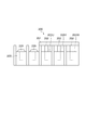
- the inverter device 200 may further include a mask member 250 that masks the AC terminals 222U, 222V, and 222W connected to the AC side of the inverter circuit 214.
- FIG. 9 is a schematic view illustrating the structure of the mask member.
- Various terminals including AC terminals 222U, 222V, 222W and the like are provided on the terminal block 220.
- a screw 229 for fixing a cable can be attached to each terminal of the terminal block 220.
- the mask member 250 includes a mask main body 251 and three insertion portions 252.
- the mask body 251 is a plate-like body that covers the AC terminals 222U, 222V, and 222W in the terminal block 220.
- the three insertion portions 252 protrude from the mask body 251 and are inserted into the holes of the AC terminals 222U, 222V, and 222W (holes for mounting the screws 229), respectively.
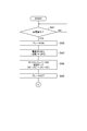
- step S41 as in step S01, the input switching control unit 311 waits for the occurrence of a power failure in the power system 2.
- step S42 as in step S02, the braking state switching unit 314 controls the brake driver 60 to switch the brake 17 from the released state to the operating state.
- step S43 as in step S03, the input switching control unit 311 controls the power supply switching unit 40 to switch the normal state to the emergency state.
- step S44 the input switching control unit 311 outputs a switching command from the AC-AC mode to the DC-AC mode to the power conversion control unit 143.
- the power conversion control unit 143 switches the control mode of the matrix converter circuit 111 from the AC-AC mode to the DC-AC mode.
- step S45 as in step S07, the braking state switching unit 314 controls the brake driver 60 to switch the brake 17 from the operating state to the released state.
- step S51 the power conversion control unit 143 controls the matrix converter circuit 111 so as to start the rescue operation.
- step S52 as in step S12, the consumption control unit 241 confirms whether or not the DC bus voltage exceeds the threshold value.
- step S52 If it is determined in step S52 that the DC bus voltage exceeds the threshold, the power conversion system 20A executes step S53. If it is determined in step S52 that the DC bus voltage does not exceed the threshold, the power conversion system 20A Step S54 is executed. In step S53, the control circuit 240 turns on the changeover switch 232 in the same manner as in step S13, and in step S54, the control circuit 240 turns off the changeover switch 232 in the same manner as in step S14.
- step S55 the power conversion control unit 143 confirms whether or not the lifting body 12 has reached the rescue position.
- step S55 when it determines with the raising / lowering body 12 not having reached
- step S55 When it is determined in step S55 that the lifting body 12 has reached the rescue position, the power conversion system 20A executes step S56.
- step S56 the power conversion control unit 143 controls the matrix converter circuit 111 so as to stop the rescue operation.
- step S61 the brake driver 60 is controlled so that the brake state switching unit 314 switches the brake 17 from the released state to the activated state, as in step S21.
- step S62 as in step S22, the input switching control unit 311 waits for cancellation of the power failure in the power system 2.
- step S63 as in step S25, the input switching control unit 311 controls the power supply switching unit 40 so as to switch the emergency state to the normal state.
- step S64 the input switching control unit 311 outputs a switching command from the DC-AC mode to the AC-AC mode to the power conversion control unit 143.
- step S65 as in step S27, the brake driver 60 controls the brake state switching unit 314 to switch the brake 17 from the operating state to the released state. This completes the procedure for switching between the normal state and the emergency state.
- the power conversion system 20 repeats the above procedure.
- steps S43 and S44 can be changed as appropriate.
- steps S63 and S64 can be changed as appropriate.
- the power conversion system 20B according to the third embodiment is the first in that it consumes regenerative power without converting the power between the uninterruptible power supply 3 and the power conversion unit 30. Different from the power conversion system 20A according to the second embodiment.
- the emergency input lines 25R, 25S, and 25T from the uninterruptible power supply 3 are connected to the primary terminals 113R, 113S, and 113T, respectively, and the power supply switching unit 40
- the selector switches 43R, 43S, and 43T are provided on the emergency input lines 25R, 25S, and 25T, respectively.
- the power conversion system 20 ⁇ / b> B includes a power consumption unit 70 instead of the power consumption unit 50.
- the power consumption unit 70 includes three resistance elements 71, 72, 73 and a consumption state switching unit 74.
- the consumption state switching unit 74 is a consumption on state in which the resistance elements 71, 72, 73 are connected between the phases of the AC power from the uninterruptible power supply 3, and a consumption off state in which the resistance elements 71, 72, 73 are not connected between the phases. Are switched according to the generation state of the regenerative power.
- the consumption state switching unit 74 includes changeover switches 75, 76, and 77.
- the changeover switch 75 is connected in series with the resistance element 71 between the emergency input lines 25R and 25S.
- the changeover switch 76 is connected in series with the resistance element 71 between the emergency input lines 25S and 25T.
- the changeover switch 77 is connected in series with the resistance element 73 between the emergency input lines 25R and 25T.
- the consumption state switching unit 74 switches the on / off of the changeover switches 75, 76, and 77 according to the generation state of regenerative power from the secondary side of the power conversion unit 30. For example, the consumption state switching unit 74 switches the changeover switches 75, 76, and 77 to the on state according to the increase in the regenerative power, and switches the changeover switches 75, 76, and 77 to the off state according to the decrease in the regenerative power.
- the consumption state switching unit 74 switches on / off of the changeover switches 75, 76, 77 based on the DC voltage value between the DC buses 123P, 123N of the snubber circuit 120. For example, when the DC voltage value detected by the voltage sensor 115 is below a predetermined threshold value, the consumption state switching unit 74 keeps the changeover switches 75, 76, and 77 in the OFF state, and the DC voltage value is set to the threshold value. When exceeded, the changeover switches 75, 76, and 77 are turned on.
- the consumption state switching unit 74 may be configured in any manner as long as the consumption on state and the consumption off state are switched according to the generation state of the regenerative power. The switching need not necessarily be based on the DC voltage value between the DC buses 123P and 123N. For example, the consumption state switching unit 74 may switch between the consumption on state and the consumption off state depending on whether or not regenerative power is generated. As described above, whether or not regenerative power is generated can be detected based on, for example, whether the elevating body 12 is raised or lowered.
- the control circuit 140 controls the matrix converter circuit 111 so as to perform AC-AC conversion between the primary side and the secondary side even in the emergency state. That is, the control circuit 140 has the AC-AC conversion control unit 141 instead of the power conversion control unit 143.
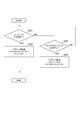
- step S71 the input switching control unit 311 waits for the occurrence of a power failure in the power system 2.
- step S72 as in step S02, the braking state switching unit 314 controls the brake driver 60 to switch the brake 17 from the released state to the operating state.
- step S73 as in step S03, the input switching control unit 311 controls the power supply switching unit 40 to switch the normal state to the emergency state.
- step S74 as in step S07, the braking state switching unit 314 controls the brake driver 60 to switch the brake 17 from the operating state to the released state.
- step S81 as in step S51, the power conversion control unit 143 controls the matrix converter circuit 111 so as to start the rescue operation.
- step S82 the consumption state switching unit 74 checks whether or not the voltage value between the DC buses 123P and 123N detected by the voltage sensor 115 (hereinafter referred to as “DC bus voltage”) exceeds the threshold value.
- step S82 If it is determined in step S82 that the DC bus voltage exceeds the threshold, the power conversion system 20B executes step S83. If it is determined in step S82 that the DC bus voltage does not exceed the threshold, the power conversion system 20B Step S84 is executed. In step S83, the consumption state switching unit 74 turns on the changeover switches 75, 76, and 77, and in step S84, the consumption state switching unit 74 turns off the changeover switches 75, 76, and 77.
- step S85 the power conversion control unit 143 confirms whether or not the lifting body 12 has reached the rescue position.
- step S85 when it determines with the raising / lowering body 12 not having reached
- step S85 If it is determined in step S85 that the lifting body 12 has reached the rescue position, the power conversion system 20B executes step S86.
- step S86 the power conversion control unit 143 controls the matrix converter circuit 111 so as to stop the rescue operation.
- step S91 similarly to step S21, the brake state switching unit 314 controls the brake driver 60 so as to switch the brake 17 from the released state to the activated state.
- step S92 as in step S22, the input switching control unit 311 waits for the cancellation of the power failure in the power system 2.
- step S93 as in step S25, the input switching control unit 311 controls the power supply switching unit 40 so as to switch the emergency state to the normal state.
- step S94 similarly to step S27, the brake driver 60 controls the brake driver 60 so that the brake 17 switches the brake 17 from the operating state to the released state. This completes the procedure for switching between the normal state and the emergency state.
- the power conversion system 20B repeats the above procedure.
- the power conversion system 20C according to the fourth embodiment is a power conversion according to the second embodiment in that the power conversion unit 30 is disconnected from the uninterruptible power supply 3 and regenerative power is consumed. Different from the system 20A. As shown in FIG. 16, in the power conversion system 20C, the emergency input lines 25R, 25S, and 25T from the uninterruptible power supply 3 are connected to the primary terminals 113R, 113S, and 113T, respectively, and the power switching unit 40 The selector switches 43R, 43S, and 43T are provided on the emergency input lines 25R, 25S, and 25T, respectively.
- the power conversion system 20 ⁇ / b> C includes a power consumption unit 80 instead of the power consumption unit 50.
- the power consumption unit 80 includes a resistance element 81, consumption lines 82R, 82S, and 82T, and a consumption state switching unit 84.
- the consumption lines 82R and 82S branch from the emergency input lines 25R and 25S at the branch points 83R and 83S, respectively, and are connected to one end side of the resistance element 81.
- the consumption line 82T branches from the emergency input line 25T at the branch point 83T and is connected to the other end side of the resistance element 81.
- the consumption state switching unit 84 includes a consumption ON state in which the resistance element 81 is connected to the primary side of the power conversion unit 30 and the uninterruptible power supply 3 is not connected to the primary side of the power conversion unit 30, and the resistance element 81 is the power conversion unit.
- the power-off state in which the uninterruptible power supply 3 is connected to the primary side of the power conversion unit 30 without being connected to 30 is switched according to the generation state of the regenerative power.
- the consumption state switching unit 84 includes changeover switches 85R, 85S, and 85T and changeover switches 86R, 86S, and 86T.
- the change-over switches 85R, 85S, and 85T are provided on the emergency input lines 25R, 25S, and 25T between the uninterruptible power supply 3 and the branch points 83R, 83S, and 83T, respectively.
- the changeover switches 86R, 86S, 86T are provided on the consumption lines 82R, 82S, 82T, respectively.
- the consumption state switching unit 84 switches on / off of the changeover switches 85R, 85S, 85T and the changeover switches 86R, 86S, 86T according to the generation state of the regenerative power from the secondary side of the power conversion unit 30.
- the consumption state switching unit 84 switches the changeover switches 85R, 85S, and 85T to the off state and switches the changeover switches 86R, 86S, and 86T to the on state according to the increase in the regenerative power. Further, the consumption state switching unit 84 switches the changeover switches 85R, 85S, and 85T to the on state and switches the changeover switches 86R, 86S, and 86T to the off state in accordance with the decrease in the regenerative power.
- the consumption state switching unit 84 switches on / off of the switch 85R, 85S, 85T and the switch 86R, 86S, 86T based on the DC voltage value between the DC buses 123P, 123N of the snubber circuit 120. .
- the consumption state switching unit 84 keeps the changeover switches 85R, 85S, and 85T in the on state and sets the changeover switches 86R, 86S, and 86T. Keep it off.
- the consumption state switching unit 84 switches the changeover switches 85R, 85S, and 85T to the off state and switches the changeover switches 86R, 86S, and 86T to the on state.
- the consumption state switching unit 84 may be configured in any manner as long as the consumption on state and the consumption off state are switched according to the generation state of the regenerative power. The switching need not necessarily be based on the DC voltage value between the DC buses 123P and 123N. For example, the consumption state switching unit 84 may switch between the consumption on state and the consumption off state depending on whether or not regenerative power is generated. As described above, whether or not regenerative power is generated can be detected based on, for example, whether the elevating body 12 is raised or lowered.
- the emergency input lines 25R and 25S are short-circuited in the consumption-on state. Therefore, the control circuit 140 (power conversion control unit 143) of the power conversion unit 30 controls the AC-AC mode in the normal state and the consumption off state, and controls the DC-AC mode in the consumption on state.
- the control circuit 140 power conversion control unit 143 of the power conversion unit 30 controls the AC-AC mode in the normal state and the consumption off state, and controls the DC-AC mode in the consumption on state.
- (2) Power Conversion Method Subsequently, the procedure for switching between the normal state and the emergency state by the power conversion system 20C will be described. As shown in FIG. 17, the power conversion system 20C first executes steps S101, S102, S103, and S104 in order. In step S101, as in step S01, the input switching control unit 311 waits for the occurrence of a power failure in the power system 2.
- step S102 as in step S02, the braking state switching unit 314 controls the brake driver 60 to switch the brake 17 from the released state to the operating state.
- step S103 as in step S03, the input switching control unit 311 controls the power supply switching unit 40 to switch the normal state to the emergency state.
- step S104 as in step S07, the braking state switching unit 314 controls the brake driver 60 to switch the brake 17 from the operating state to the released state.
- step S111 the power conversion control unit 143 controls the matrix converter circuit 111 so as to start the rescue operation.
- step S112 the power conversion control unit 143 checks whether or not the voltage value between the DC buses 123P and 123N detected by the voltage sensor 115 (hereinafter referred to as “DC bus voltage”) exceeds the threshold value.
- step S112 When it is determined in step S112 that the DC bus voltage exceeds the threshold, the power conversion system 20C sequentially executes steps S113 and S114. In step S112, when it is determined that the DC bus voltage does not exceed the threshold, power conversion The system 20C executes steps S115 and S116.
- step S113 the power conversion control unit 143 sets the control mode of the matrix converter circuit 111 to the DC-AC mode.
- step S ⁇ b> 114 the power conversion control unit 143 outputs a consumption on state command to the consumption state switching unit 84. In response to this, the consumption state switching unit 84 turns off the changeover switches 85R, 85S, and 85T and turns on the changeover switches 86R, 86S, and 86T.
- step S ⁇ b> 115 power conversion control unit 143 outputs a consumption off state command to consumption state switching unit 84.
- the consumption state switching unit 84 turns on the changeover switches 85R, 85S, and 85T and turns off the changeover switches 86R, 86S, and 86T.
- step S116 the power conversion control unit 143 sets the control mode of the matrix converter circuit 111 to the AC-AC mode.
- step S117 the power conversion control unit 143 checks whether or not the lifting body 12 has reached the rescue position.
- step S117 when it determines with the raising / lowering body 12 not having reached
- step S117 If it is determined in step S117 that the lifting body 12 has reached the rescue position, the power conversion system 20C executes step S118.
- step S118 the power conversion control unit 143 controls the matrix converter circuit 111 so as to stop the rescue operation.
- the power conversion system 20C next executes steps S121, S122, S123, and S124 in order.
- step S121 similarly to step S21, the brake state switching unit 314 controls the brake driver 60 so as to switch the brake 17 from the released state to the activated state.
- step S122 as in step S22, the input switching control unit 311 waits for the cancellation of the power failure in the power system 2.
- step S123 as in step S25, the input switching control unit 311 controls the power supply switching unit 40 so as to switch the emergency state to the normal state.
- step S124 similarly to step S27, the brake state switching unit 314 controls the brake driver 60 so as to switch the brake 17 from the operating state to the released state. This completes the procedure for switching between the normal state and the emergency state.
- the power conversion system 20C repeats the above procedure.
- the power conversion system 20 includes the matrix converter circuit 111, and bidirectional electric power between the primary side AC power and the secondary side AC power by the matrix converter circuit 111.
- a power conversion unit 30 that performs conversion, a normal state in which the power system 2 is connected to the primary side of the power conversion unit 30, and an emergency state in which the emergency uninterruptible power supply 3 is connected to the primary side of the power conversion unit
- a power consuming unit 50 connected between the uninterruptible power supply 3 and the power converting unit 30 and consuming regenerative power from the secondary side to the primary side.
- the emergency uninterruptible power supply 3 does not have a route for returning power to the power system in order to store emergency power.
- the uninterruptible power supply 3 When the uninterruptible power supply 3 is connected to the primary side of the power converter 30, an overvoltage may occur in the uninterruptible power supply 3 due to regenerative power from the secondary side to the primary side.
- the power conversion system includes a power consuming unit 50 that is connected between the uninterruptible power supply 3 and the power converting unit 30 and that consumes regenerative power from the secondary side to the primary side.
- the power consumption unit is generated by the rectifier circuit 211 that converts the AC power from the uninterruptible power supply 3 into DC power and outputs the DC power to the power converter 30 side, the resistance element 233 for power consumption, and the rectifier circuit 211.
- a changeover switch 232 that switches between the two.
- the power consumption configuration can be simplified by directing the power at the location where the resistance element 233 is disposed.
- the regenerative power can be consumed collectively between the positive electrode side and the negative electrode side of the DC power by making the power in the power consumption unit 50 DC.
- the changeover switch 232 may switch between the consumption on state and the consumption off state based on the DC voltage value between the positive electrode side and the negative electrode side. In this case, since the generation state of the regenerative power is detected in the vicinity of the resistance element 233, the consumption on state and the consumption off state can be quickly switched according to the generation state of the regenerative power.
- the power converter 30 performs AC-AC conversion between the primary side and the secondary side in a normal state, and performs a DC-AC conversion between the primary side and the secondary side in an emergency state.
- a power conversion control unit 143 for controlling 111 may be further included. In this case, the DC power generated by the rectifier circuit can be input to the power converter without being converted to AC again. For this reason, the system configuration can be simplified.
- the power conversion system 20 may include an inverter device 200 including a rectifier circuit 211, a changeover switch 232, and an inverter circuit 214 that converts DC power generated by the rectifier circuit 211 into AC power.
- an inverter device 200 including a rectifier circuit 211, a changeover switch 232, and an inverter circuit 214 that converts DC power generated by the rectifier circuit 211 into AC power.
- Inverter device 200 has DC terminals 223P and 223N connected to the DC side of inverter circuit 214, and power supply switching unit 40 connects DC terminals 223P and 223N to the primary side of power conversion unit 30 in an emergency state. Also good.
- the power consumption unit 50 can be configured more easily by using the DC terminals 223P and 223N of the inverter device 200 for connection to the primary side of the power conversion unit 30.
- the inverter device 200 may further include AC terminals 222U, 222V, and 222W connected to the AC side of the inverter circuit 214, and a mask member 250 that masks the AC terminals 222U, 222V, and 222W.
- a mask member 250 that masks the AC terminals 222U, 222V, and 222W.
- the power converter 30 includes a matrix converter circuit 111 for AC-AC conversion, an inverter circuit 214 for DC-AC conversion, and a matrix between the primary side and the secondary side according to switching between a normal state and an emergency state. And an output switching unit 31 that switches between an AC-AC conversion state to which the converter circuit 111 is connected and a DC-AC conversion state to which an inverter circuit is connected between the primary side and the secondary side. .
- the inverter circuit 214 is connected between the primary side and the secondary side in an emergency state, the DC power generated by the rectifier circuit 211 can be input to the power conversion unit 30 without being converted to AC again. . For this reason, the system configuration can be simplified.
- the power conversion system 20 switches the output so that the matrix converter circuit 111 and the inverter circuit 214 are not connected between the primary side and the secondary side, and the AC-AC conversion state and the DC-AC conversion state are switched.
- An output switching control unit 312 that controls the unit 31 may be further provided. In this case, it is possible to suppress the occurrence of an overcurrent abnormality or the like caused by both the matrix converter circuit 111 and the inverter circuit 214 supplying power to the same load.
- the power conversion system 20 includes a matrix converter device 100 having a matrix converter circuit 111 and an AC-AC conversion control unit 141 that controls the matrix converter circuit 111 so as to perform AC-AC conversion, a rectifier circuit 211, and consumption control.
- the inverter device 200 may include a unit 241, an inverter circuit 214, and a DC-AC conversion control unit 242 that controls the inverter circuit 214 to perform DC-AC conversion.
- the power conversion system can be easily configured by diverting the hardware of the existing inverter device 200 and matrix converter device 100.
- the DC-AC conversion control unit 242 may control the inverter circuit 214 so as to gradually increase the output power at the start of the DC-AC conversion state. In this case, a sudden change in output power due to a phase shift between the AC power supplied by the matrix converter circuit 111 and the AC power started by the inverter circuit 214 can be suppressed.
- the power conversion system 20 may further include a parameter transfer unit 313 that transfers a parameter related to the load connected to the secondary side of the power conversion unit 30 from one side of the matrix converter device 100 and the inverter device 200 to the other side. Good. In this case, since it is not necessary to reset parameters when replacing either the matrix converter device 100 or the inverter device 200, the usability is improved.
- the power consuming unit 70 includes a resistance element 71, 72, 73 for power consumption, a consumption on state in which the resistance elements 71, 72, 73 are connected between the phases of the AC power from the uninterruptible power supply 3, and a resistance between the phases.
- the power converter 30 includes a matrix converter circuit 111, a control circuit 140 that controls the matrix converter circuit 111 to perform AC-AC conversion between the primary side and the secondary side, and a rectifier circuit 122 that converts the regenerative power into DC.
- the consumption control unit 241 may switch between the consumption on state and the consumption off state based on the DC voltage value of the snubber circuit 120. In this case, by using the snubber circuit 120 of the power conversion unit 30, it is possible to easily detect the switching timing of the consumption on state and the consumption off state.
- the power consuming unit 70 includes power consuming resistive elements 71, 72, 73, the resistive elements 71, 72, 73 are connected to the primary side of the power converter 30, and the uninterruptible power supply 3 is the primary of the power converter 30.
- a consumption state switching unit 74 that switches according to the power generation state.
- the regenerative power can be more reliably guided to the resistance elements 71, 72, and 73 by switching between the consumption on state and the consumption off state.
- the power conversion unit 30 controls the matrix converter circuit 111 to perform AC-AC conversion between the primary side and the secondary side in the normal state and the consumption-off state, and in the consumption-on state. And a control circuit 140 that controls the matrix converter 111 circuit so as to perform DC-AC conversion between the primary side and the secondary side.
- the configuration for power consumption can be simplified by converting the regenerative power into direct current and guiding it to the resistance element 81.
- the lifting system 1 includes a matrix converter circuit 111, a power conversion unit 30 that performs bidirectional power conversion between the primary side AC power and the secondary side AC power by the matrix converter circuit 111, and a power system 2.
- a power switching unit 40 for switching between a normal state in which the power converter 30 is connected to the primary side and an emergency state in which the emergency uninterruptible power supply 3 is connected to the primary side of the power converter 30, and an uninterruptible power supply
- a power consumption unit 50 connected between the device 3 and the power conversion unit 30 and consuming regenerative power from the secondary side to the primary side, a motor 16 connected to the secondary side of the power conversion unit 30, and the motor 16 And an elevating body 12 that elevates and lowers by the power of.
- the elevating system 1 further includes a brake 17 that applies a braking force to the elevating body 12, and a braking state switching unit 314 that switches between an operating state and a released state of the brake 17, and the power conversion unit 30 includes an AC-AC A matrix converter circuit 111 for conversion, an inverter circuit 214 for DC-AC conversion, and an AC- in which the matrix converter circuit 111 is connected between the primary side and the secondary side in accordance with switching between the normal state and the emergency state An output switching unit 31 that switches between an AC conversion state and a DC-AC conversion state in which the inverter circuit 214 is connected between the primary side and the secondary side.
- the output switching unit 31 includes the matrix converter circuit 111 and After the inverter circuit 214 is not connected between the primary side and the secondary side, the AC-AC conversion state and the DC-AC conversion are performed.
- the braking state switching unit 314 operates the brake 17 when power is not supplied from the power conversion unit 30 to the motor 16, and the brake state switching unit 314 operates the brake 17 when power is supplied from the power conversion unit 30 to the motor 16. You may cancel. In this case, it is possible to suppress the occurrence of an overcurrent abnormality or the like caused by both the matrix converter circuit 111 and the inverter circuit 214 supplying power to the motor 16. Thereby, it is easier to ensure the driving power of the motor 16 in an emergency.
- the brake 17 operates in a state where neither the matrix converter circuit 111 nor the inverter circuit 214 is connected between the primary side and the secondary side, the elevating body 12 is prevented from dropping in this state. Therefore, the rescue operation of the lifting body 12 in an emergency can be performed more reliably.
- the power conversion system 20 includes a matrix converter circuit 111 for AC / AC conversion and an inverter circuit 214 for DC / AC conversion, and performs power conversion bidirectionally between the primary side and the secondary side.
- Unit 30 a normal state in which power system 2 is connected to the primary side of power conversion unit 30, and an emergency state in which uninterruptible power supply 3 different from power system 2 is connected to the primary side of power conversion unit 30
- a power source switching unit 40 for switching between, and an AC-AC conversion state in which the matrix converter circuit 111 is connected between the primary side and the secondary side according to switching between the normal state and the emergency state, and the primary side and the secondary side
- An output switching unit 31 for switching between a DC-AC conversion state to which an inverter circuit 214 is connected.
- the regenerative power of the motor 16 can be returned to the power system 2 for effective use.
- the inverter circuit 214 is connected between the uninterruptible power supply 3 and the motor 16, whereby the regenerative power of the motor 16 can be converted into a direct current between the inverter circuit 214 and the uninterruptible power supply 3. it can.
- voltage control between the inverter circuit 214 and the uninterruptible power supply 3 is facilitated, and it is easy to suppress application of overvoltage to the uninterruptible power supply 3 due to regenerative power. Therefore, it is effective to achieve both effective utilization of the regenerative power of the motor 16 and power supply to the motor 16 in an emergency.
- the power conversion system 20 includes an output switching unit that switches between an AC-AC conversion state and a DC-AC conversion state through a state in which neither the matrix converter circuit 111 nor the inverter circuit 214 is connected between the primary side and the secondary side. Further, an output switching control unit 312 for controlling 31 may be provided. In this case, it is possible to suppress the occurrence of an overcurrent abnormality or the like caused by both the matrix converter circuit 111 and the inverter circuit 214 supplying power to the same load.
- the power conversion system 20 includes a matrix converter device 111 having a matrix converter circuit 111 and an AC-AC conversion control unit 141 that controls the matrix converter circuit 111 to perform AC-AC conversion, an inverter circuit 214, and a DC- And an inverter device 200 having a DC-AC conversion control unit 242 that controls the inverter circuit 214 so as to perform AC conversion.
- the power conversion system 20 can be easily configured by using the hardware of the existing inverter device 200 and the matrix converter device 100.
- the DC-AC conversion control unit 242 may control the inverter circuit 214 so as to gradually increase the output power at the start of the DC-AC conversion state. In this case, a sudden change in output power due to a phase shift between the AC power supplied by the matrix converter circuit 111 and the AC power started by the inverter circuit 214 can be suppressed.
- the power conversion system 20 further includes a parameter transfer unit 313 that transfers parameters related to the motor 16 connected to the secondary side of the power conversion unit 30 from one side of the matrix converter device 100 and the inverter device 200 to the other side. Also good. In this case, since it is not necessary to reset parameters when replacing either the matrix converter device 100 or the inverter device 200, the usability is improved.
- the power conversion system 20 further includes a power consumption unit 50 that is connected between the uninterruptible power supply 3 and the inverter circuit 214 and that consumes regenerative power from the motor 16 connected to the secondary side of the power conversion unit 30. It may be.
- the power consumption unit 50 can be provided between the uninterruptible power supply 3 and the inverter circuit 214 between the positive electrode side and the negative electrode side of the DC power, the configuration for power consumption can be simplified. Become.
- the power consuming unit 50 includes a power consuming resistance element 233 and a power-on state in which the resistance element 233 is connected between the positive electrode side and the negative electrode side of the DC power between the uninterruptible power supply 3 and the inverter circuit 214. And a changeover switch 232 that switches between a power-off state in which the resistance element 233 is not connected between the positive electrode side and the negative electrode side according to the generation state of the regenerative power. In this case, application of overvoltage to the uninterruptible power supply 3 can be suppressed with a simple configuration in which the resistance element 233 and the changeover switch 232 are arranged between the positive electrode side and the negative electrode side.
- the changeover switch 232 may switch between the consumption on state and the consumption off state based on the DC voltage value between the positive electrode side and the negative electrode side. In this case, since the generation state of the regenerative power is detected in the vicinity of the resistance element 233, the consumption on state and the consumption off state can be quickly switched according to the generation state of the regenerative power.
- the lifting system 1 includes a motor 16, a lifting body 12 that moves up and down by the power of the motor 16, a power system 2, a matrix converter circuit 111 that performs power conversion between the motor 16, and a power system 2.
- Inverter circuit 214 that performs power conversion between the power failure power supply 3 and the motor 16, an AC-AC conversion state in which the matrix converter circuit 111 is connected to the motor 16, and a DC that the inverter circuit 214 is connected to the motor 16
- An output switching unit 31 that switches between AC conversion states may be provided.
- the elevating system 1 includes the power conversion system 20 described above, which is effective in achieving both the effective use of the regenerative power of the motor 16 during normal time and the performance of the rescue operation of the elevating body 12 during an emergency. is there.
- the lifting system 1 includes a brake 17 that applies a braking force to the lifting body 12, a braking state switching unit 314 that switches between an operating state and a releasing state of the brake 17, a matrix converter circuit 111, and an inverter circuit 214. And an output switching control unit 312 that switches between an AC-AC conversion state and a DC-AC conversion state through a state that is not connected to the control circuit, and the braking state switching unit 314 is supplied from either the matrix converter circuit 111 or the inverter circuit 214.
- the brake 17 may be operated when power is not supplied to the motor 16, and may be released when power is supplied from the matrix converter circuit 111 or the inverter circuit 214 to the motor 16.
- the emergency power source may be a DC power source.
- a power conversion system 20D of FIG. 20 is obtained by replacing the uninterruptible power supply 3 of the first embodiment with a DC battery 4.
- the positive and negative electrodes on the secondary side (output side) of the battery 4 are connected to the DC terminals 223P and 223N of the matrix converter device 100 via emergency input lines 26P and 26N, respectively.
- the power supply switching unit 40 of the power conversion system 20D includes changeover switches 44P and 44N provided on the emergency input lines 26P and 26N, respectively, instead of the changeover switches 43R, 43S, and 43T.
- the power supply switching unit 40 connects the battery 4 to the DC terminals 223P and 223N in the emergency state. According to such a configuration, the power consumption unit can be configured more easily by using the DC terminal of the inverter device for connection to the primary side of the power conversion unit.
- the inverter device 200 of the power conversion system 20D may further include a mask member 260 that masks the AC terminals 221R, 221S, and 221T.
- FIG. 21 is a schematic view illustrating the structure of the mask member. Similar to the mask member 250, the mask member 260 includes a mask main body 261 and three insertion portions 262.
- the mask body 261 is a plate-like body that covers the AC terminals 221R, 221S, and 221T in the terminal block 220.
- the three insertion portions 262 protrude from the mask body 261 and are inserted into the holes of the AC terminals 221R, 221S, and 221T (holes for mounting the screws 229), respectively. According to such a structure, generation
- the configuration of the power conversion systems 20, 20A, 20B, 20C, and 20D can be applied to any lifting system as long as the lifting body, the electric motor, and the brake are provided. is there.
- the lifting system may be a crane system for construction work.
- a power converter having a matrix converter circuit for AC-AC conversion and an inverter circuit for DC-AC conversion, and performing bidirectional power conversion between the primary side and the secondary side;
- a power supply switching unit that switches between a normal state in which an AC power supply is connected to the primary side of the power conversion unit and an emergency state in which an emergency power supply different from the AC power supply is connected to the primary side of the power conversion unit
- An AC-AC conversion state in which the matrix converter circuit is connected between the primary side and the secondary side according to switching between the normal state and the emergency state, and between the primary side and the secondary side
- An output switching unit that switches between a DC-AC conversion state to which the inverter circuit is connected.
- the output switching unit is configured to switch between the AC-AC conversion state and the DC-AC conversion state through a state in which neither the matrix converter circuit nor the inverter circuit is connected between the primary side and the secondary side.
- Appendix 3 A matrix converter device having the matrix converter circuit and an AC-AC conversion control unit for controlling the matrix converter circuit to perform AC-AC conversion;
- the power conversion system according to appendix 1 or 2 comprising the inverter circuit and an inverter device having a DC-AC conversion control unit that controls the inverter circuit to perform DC-AC conversion.
- the inverter device has a DC terminal connected to the DC side of the inverter circuit,
- the emergency power source is a DC power source,
- the power conversion system according to any one of appendices 3 to 5, wherein the power supply switching unit connects the emergency power supply to the DC terminal in the emergency state.
- the inverter device is AC terminal, The power conversion system according to appendix 6, further comprising: a rectifier circuit connected between the AC terminal and a DC side of the inverter circuit; and a mask member that masks the AC terminal.
- Appendix 8 Any one of appendixes 1 to 7, further comprising a power consuming unit that is connected between the emergency power source and the inverter circuit and that consumes regenerative power from a load connected to the secondary side of the power converter.
- the power conversion system according to one item.
- the power consumption unit A resistive element for power consumption; Consumption ON state in which the resistance element is connected between the positive electrode side and the negative electrode side of DC power between the emergency power supply and the inverter circuit, and consumption in which the resistance element is not connected between the positive electrode side and the negative electrode side
- the power conversion system according to appendix 8 further comprising: a consumption state switching unit that switches an off state according to the generation state of the regenerative power.
- Appendix 10 The power conversion system according to appendix 9, wherein the consumption state switching unit switches between the consumption on state and the consumption off state based on a DC voltage value between the positive electrode side and the negative electrode side.
- a brake for applying a braking force to the lifting body A braking state switching unit that switches between an operating state and a released state of the brake; An output switching control unit that switches between the AC-AC conversion state and the DC-AC conversion state through a state in which neither the matrix converter circuit nor the inverter circuit is connected to the electric motor, The braking state switching unit operates the brake when electric power is not supplied to the electric motor from either the matrix converter circuit or the inverter circuit, and electric power is supplied to the electric motor from the matrix converter circuit or the inverter circuit.
- the lifting system according to appendix 11, wherein the brake is released when the brake is applied.
- the power conversion system and the power conversion method according to the present disclosure can be used for, for example, a lifting system.
- SYMBOLS 1 Elevating system, 2 ... Electric power system (1st alternating current power supply, alternating current power supply), 3 ... Uninterruptible power supply device (2nd alternating current power supply, emergency power supply), 12 ... Elevating body, 16 ... Motor (electric motor, alternating current type) Load), 17 ... brake, 20, 20A, 20B, 20C, 20D ... power conversion system, 30 ... power conversion unit, 31 ... output switching unit, 40 ... power source switching unit, 50, 70, 80 ... power consumption unit, 71 , 72, 73, 81... Resistance element, 74... Consumption state switching unit, 100... Matrix converter device, 111... Matrix converter circuit, 120 ...
- snubber circuit 122 ... rectifier circuit, 140 ... control circuit, 143.
- 200 ... inverter device, 211 ... rectifier circuit, 214 ... inverter circuit, 222U, 222V, 222W ... AC terminal, 223P, 223N ... DC terminal, 232 ... off Switch (consumption state switching unit), 233... Resistance element, 241... Consumption control unit, 242... DC-AC conversion control unit, 250, 260... Mask member, 312 ... output switching control unit, 313. Braking state switching unit.
Landscapes
- Engineering & Computer Science (AREA)
- Power Engineering (AREA)
- Business, Economics & Management (AREA)
- Emergency Management (AREA)
- Ac-Ac Conversion (AREA)
- Inverter Devices (AREA)
Abstract
電力変換システム20は、マトリクスコンバータ回路111を有し、当該マトリクスコンバータ回路111により一次側の交流電力及び二次側の交流電力の間で双方向の電力変換を行う電力変換部30と、電力系統2が電力変換部30の一次側に接続される通常状態と、非常用の無停電電源装置3が電力変換部の一次側に接続される非常状態とを切り替える電源切替部と、無停電電源装置3及び電力変換部30の間に接続され、二次側から一次側への回生電力を消費する電力消費部50と、を備える。
Description
本開示は、電力変換システム、昇降システム及び電力変換方法に関する。
特許文献1には、双方向スイッチモジュールを有するPWMサイクロコンバータ装置と、電源切り替え器とを備えるシステムが開示されている。電源切り替え器は、三相交流電源からの三相出力を双方向スイッチモジュールに出力する状態と、蓄電池の電圧を双方向スイッチモジュールに出力する状態とを切り替える。
本開示は、非常時の電源を確保し易いマトリクスコンバータ式の電力変換システムを提供することを目的とする。
本開示の一側面に係る電力変換システムは、マトリクスコンバータ回路を有し、当該マトリクスコンバータ回路により一次側の交流電力及び二次側の交流電力の間で双方向の電力変換を行う電力変換部と、第一交流電源が電力変換部の一次側に接続される通常状態と、非常用の第二交流電源が電力変換部の一次側に接続される非常状態とを切り替える電源切替部と、第二交流電源及び電力変換部の間に接続され、二次側から一次側への回生電力を消費する電力消費部と、を備える。
本開示の他の側面に係る昇降システムは、マトリクスコンバータ回路を有し、当該マトリクスコンバータ回路により一次側の交流電力及び二次側の交流電力の間で双方向の電力変換を行う電力変換部と、第一交流電源が電力変換部の一次側に接続される通常状態と、非常用の第二交流電源が電力変換部の一次側に接続される非常状態とを切り替える電源切替部と、第二交流電源及び電力変換部の間に接続され、二次側から一次側への回生電力を消費する電力消費部と、電力変換部の二次側に接続された電動機と、電動機の動力によって昇降する昇降体と、を備える。
本開示の更に他の側面に係る電力変換方法は、マトリクスコンバータ回路を有し、当該マトリクスコンバータ回路により一次側の交流電力及び二次側の交流電力の間で双方向の電力変換を行う電力変換部の一次側に第一交流電源が接続される通常状態と、非常用の第二交流電源が電力変換部の一次側に接続される非常状態とを切り替えるように電源切替部を制御することと、非常状態において、二次側から一次側への回生電力を消費するように電力消費部を制御することと、を含む。
本開示によれば、非常時の電源を確保し易いマトリクスコンバータ式の電力変換システムを提供することができる。
以下、実施形態について、図面を参照しつつ詳細に説明する。説明において、同一要素又は同一機能を有する要素には同一の符号を付し、重複する説明を省略する。
1.第一実施形態
(1)昇降システム
図1に示す昇降システム1は、例えばエレベータシステムであり、昇降体12と、巻上機13と、錘14と、ワイヤロープ15と、ブレーキ17と、電力変換システム20とを備える。ワイヤロープ15は、その両端部が下方に垂れ下がるように巻上機13にかけられている。昇降体12は、利用者が搭乗する乗りかごであり、ワイヤロープ15の一端部に接続されている。錘14は、ワイヤロープ15を介して昇降体12の重量に抗する張力をワイヤロープ15に発生させるためのカウンターウェイトである。巻上機13は、昇降体12側に垂れ下がるワイヤロープ15の長さ、及び錘14側に垂れ下がるワイヤロープ15の長さの比を変更するように回転する。
(1)昇降システム
図1に示す昇降システム1は、例えばエレベータシステムであり、昇降体12と、巻上機13と、錘14と、ワイヤロープ15と、ブレーキ17と、電力変換システム20とを備える。ワイヤロープ15は、その両端部が下方に垂れ下がるように巻上機13にかけられている。昇降体12は、利用者が搭乗する乗りかごであり、ワイヤロープ15の一端部に接続されている。錘14は、ワイヤロープ15を介して昇降体12の重量に抗する張力をワイヤロープ15に発生させるためのカウンターウェイトである。巻上機13は、昇降体12側に垂れ下がるワイヤロープ15の長さ、及び錘14側に垂れ下がるワイヤロープ15の長さの比を変更するように回転する。
駆動装置11は、モータ16(電動機)を動力源として巻上機13を回転させ、昇降体12を昇降させる。すなわち、昇降体12はモータ16の動力によって昇降する。ブレーキ17は、昇降体12に対して制動力を付与する。ブレーキ17の具体例としては、巻上機13に対して制動力を付与するディスクブレーキ等の機械式ブレーキが挙げられる。
電力変換システム20は、電源とモータ16との間に介在し、電源からの電力を駆動用の交流電力に変換してモータ16に出力する。電力変換システム20は、電力変換部30と、電源切替部40と、電力消費部50と、ブレーキドライバ60と、電源マネジメント装置300とを備える。
電力変換部30は、マトリクスコンバータ回路を有し、当該マトリクスコンバータ回路により一次側(電源側)の交流電力及び二次側(モータ16側)の交流電力の間で双方向の電力変換を行う。双方向の電力変換を行うとは、一次側から二次側に交流電力を伝える電力変換と、二次側から一次側に交流電力(例えば回生電力)を伝える電力変換の両方を行い得ることを意味する。電力変換部30の一次側には、第一交流電源又は第一交流電源とは別の非常用電源が接続される。電力変換部30の二次側には、モータ16が接続される。このため電力変換部30は、第一交流電源又は非常用電源とモータ16との間で双方向の電力変換を行う。
電源切替部40は、第一交流電源が電力変換部30の一次側に接続される状態(以下、「通常状態」という。)と、非常用電源(例えば第二交流電源)が電力変換部30の一次側に接続される状態(以下、「非常状態」という。)とを切り替える。第一交流電源は、例えば三相交流の電力系統2である。第二交流電源は、例えば三相交流の無停電電源装置3である。電力消費部50は、第二交流電源と電力変換部30との間に接続され、電力変換部30の二次側から一次側への回生電力(例えばモータ16からの回生電力)を消費する。
ブレーキドライバ60は、昇降体12に対して制動力を付与する作動状態と、昇降体12に対する制動力を解除する解除状態とを切り替えるための電力をブレーキ17に供給する。
電源マネジメント装置300は、電力系統2の状態(例えば停電の発生状態)に応じて通常状態及び非常状態を切り替えるように電源切替部40を制御し、これに応じた各種指令を電力変換部30及びブレーキドライバ60に出力する。
(2)電力変換システム
以下、電力変換システム20の電力変換部30、電力消費部50、電源切替部40及び電源マネジメント装置300の構成をより詳細に例示する。上述したように、電力変換部30は、電力系統2又は無停電電源装置3からの電力を駆動用の交流電力に変換してモータ16に出力する。
以下、電力変換システム20の電力変換部30、電力消費部50、電源切替部40及び電源マネジメント装置300の構成をより詳細に例示する。上述したように、電力変換部30は、電力系統2又は無停電電源装置3からの電力を駆動用の交流電力に変換してモータ16に出力する。
図2に示すように、無停電電源装置3は、電力系統2からの交流電力を直流に変換して蓄電し、電力系統2の停電等の非常時には蓄電した直流電力を三相交流に変換して出力する。電力系統2からの交流電力を蓄電するために、無停電電源装置3の一次側は、入力ライン24R,24S,24Tを介して電力系統2に接続されている。
電力変換部30は、交流-交流変換用のマトリクスコンバータ回路111と、直流-交流変換用のインバータ回路214と、出力切替部31とを有する。マトリクスコンバータ回路111は、電力系統2と、モータ16(交流型の負荷)との間で双方向の交流-交流変換を行う。インバータ回路214は、無停電電源装置3とモータ16との間で双方向の直流-交流変換を行う。
出力切替部31は、上記通常状態及び上記非常状態の切り替えに応じて、一次側及び二次側の間にマトリクスコンバータ回路111が接続される(すなわちマトリクスコンバータ回路111がモータ16に接続される)交流-交流変換状態と、一次側及び二次側の間にインバータ回路214が接続される(すなわちインバータ回路214がモータ16に接続される)直流-交流変換状態とを切り替える。
なお、上記通常状態及び上記非常状態の切り替えに応じて交流-交流変換状態及び直流-交流変換状態を切り替えることは、上記通常状態及び上記非常状態の切り替えと交流-交流変換状態及び直流-交流変換状態の切り替えとが互いに関係することを意味しているに過ぎず、これらの間の前後関係は規定しない。すなわち出力切替部31は、上記通常状態及び上記非常状態の切り替えの後に交流-交流変換状態及び直流-交流変換状態を切り替えてもよく、上記通常状態及び上記非常状態の切り替えと同時に交流-交流変換状態及び直流-交流変換状態を切り替えてもよく、上記通常状態及び上記非常状態の切り替えに先立って交流-交流変換状態及び直流-交流変換状態を切り替えてもよい。
電力消費部50は、整流回路211と、電力消費用の抵抗素子233と、切替スイッチ232(消費状態切替部)とを有する。整流回路211は、無停電電源装置3からの交流電力を直流電力に変換して電力変換部30側に出力する。切替スイッチ232は、整流回路211により生成された直流電力の正極側及び負極側の間に抵抗素子233が接続される消費オン状態と、当該正極側及び負極側の間に抵抗素子233が接続されない消費オフ状態とを、モータ16からの回生電力の発生状況に応じて切り替える。
一例として、電力変換部30及び電力消費部50は、互いに別体としてユニット化されたマトリクスコンバータ装置100及びインバータ装置200を利用して構成されている。
マトリクスコンバータ装置100は、上述のマトリクスコンバータ回路111と、スナバ回路120と、放電回路130と、電圧センサ115と、制御回路140と、一次側端子113R,113S,113Tと、二次側端子114U,114V,114Wとを有する。
マトリクスコンバータ回路111は、一次側端子113R,113S,113T及び二次側端子114U,114V,114Wの間に設けられ、双方向の電力変換を行う。例えばマトリクスコンバータ回路111は、マトリクス状に配置された複数の双方向スイッチ112(例えば3行3列のマトリクス状に配置された9個の双方向スイッチ112)を含み、双方向スイッチ112のオン・オフによって双方向の電力変換を行う。一例として、双方向スイッチ112は、互いに逆向きとなるように並列接続された二つのIGBT(Insulated Gate Bipolar Transistor)を含む。一次側端子113R,113S,113Tは、入力ライン21R,21S,21Tをそれぞれ介して電力系統2に接続されている。二次側端子114U,114V,114Wは、出力ライン28U,28V,28Wをそれぞれ介してモータ16に接続されている。これにより、マトリクスコンバータ回路111は、電力系統2と、モータ16(交流型の負荷)との間で双方向の交流-交流変換を行う。
スナバ回路120は、少なくともマトリクスコンバータ回路111の二次側の交流電力(回生電力)を直流化して蓄電する。一例として、スナバ回路120は、マトリクスコンバータ回路111の一次側及び二次側の交流電力の両方を直流化して蓄電する。例えばスナバ回路120は、整流回路121,122と、コンデンサ124とを含む。整流回路121は、例えばダイオードブリッジ回路であり、マトリクスコンバータ回路111の一次側の交流電流を直流化して直流母線123P,123Nに供給する。整流回路122は、例えばダイオードブリッジ回路であり、マトリクスコンバータ回路111の二次側の交流電流を直流化して直流母線123P,123Nに供給する。コンデンサ124は、直流母線123P,123Nの間に接続され、直流母線123P,123Nに供給された直流電力を蓄電する。
放電回路130は、コンデンサ124を放電させる回路である。例えば放電回路130は、放電スイッチ131及び抵抗素子132を含む。放電スイッチ131及び抵抗素子132は、直流母線123P,123Nの間に直列に接続されている。放電スイッチ131は、例えばIGBTであり、直流母線123P,123Nの間に抵抗素子132が接続されるオン状態と、直流母線123P,123Nの間に抵抗素子132が接続されないオフ状態とを切り替える。放電スイッチ131をオン状態にすると、コンデンサ124に蓄電された電力が抵抗素子132において消費される。電圧センサ115は、直流母線123P,123Nの間の直流電圧を検出する。
制御回路140は、一次側(一次側端子113R,113S,113T側)の交流電力及び二次側(二次側端子114U,114V,114W側)の交流電力の間で電力変換(交流-交流変換)を行うようにマトリクスコンバータ回路111を制御する。また、制御回路140は、直流母線123P,123Nの間に抵抗素子132が接続される放電状態と、直流母線123P,123Nの間に抵抗素子132が接続されない非放電状態とを、マトリクスコンバータ回路111の二次側からの回生電力の発生状況に応じて切り替える。
例えば制御回路140は、機能上の構成(以下、「機能モジュール」という。)として、交流-交流変換制御部141及び放電制御部142を有する。交流-交流変換制御部141は、上記交流-交流変換を行うようにマトリクスコンバータ回路111を制御する。より具体的に、交流-交流変換制御部141は、所望の電力変換を実行させるように、マトリクスコンバータ回路111の複数の双方向スイッチ112に対しゲート駆動信号を出力する。放電制御部142は、上記回生電力の発生状況に応じて上記放電状態と非放電状態とを切り替えるように放電回路130を制御する。具体的に、放電制御部142は、電圧センサ115により検出される直流母線123P,123Nの間の直流電圧値に応じて放電スイッチ131のオン・オフを切り替える。例えば放電制御部142は、直流母線123P,123Nの間の直流電圧値が所定の閾値を下回っている場合には放電スイッチ131をオフ状態に保ち、当該直流電圧値が当該閾値を超えたときに放電スイッチ131をオン状態にする。
インバータ装置200は、上述の整流回路211と、上述のインバータ回路214と、上述の切替スイッチ232と、電圧センサ215と、制御回路240と、直流母線212P,212Nと、交流端子221R,221S,221Tと、交流端子222U,222V,222Wと、直流端子223P,223Nと、制動抵抗端子231P,231Nとを有する。
整流回路211は、例えばダイオードブリッジ回路であり、交流端子221R,221S,221Tに入力された交流電力を直流化して直流母線212P,212Nに出力する。
インバータ回路214は、直流母線212P,212Nの直流電力を交流電力に変換して交流端子222U,222V,222Wに出力する。インバータ回路214は、例えばIGBT等の複数のスイッチを有する。当該複数のスイッチのオン・オフを切り替えることにより、直流電力を交流電力に変換することが可能である。
直流端子223P,223Nは、交流電力に代えて直流電力を入力するための端子であり、インバータ回路214の直流側に接続されている。具体的に、直流端子223P,223Nは、直流母線212P,212Nにそれぞれ接続されている。コンデンサ213は、直流母線212P,212Nの間に接続されている。
制動抵抗端子231P,231Nは、制動抵抗等を外付けするための端子である。制動抵抗端子231Pは直流母線212Pに接続されており、制動抵抗端子231Nは切替スイッチ232を介して直流母線212Nに接続されている。切替スイッチ232は、例えばIGBTであり、制動抵抗端子231P,231Nに外付けされた制動抵抗が直流母線212P,212Nの間に接続されるオン状態と、当該制動抵抗が直流母線212P,212Nの間に接続されないオフ状態とを切り替える。電圧センサ215は、直流母線212P,212Nの間の直流電圧を検出する。
交流端子221R,221S,221Tは、非常用入力ライン25R,25S,25Tをそれぞれ介して無停電電源装置3の二次側(出力側)に接続されている。交流端子222U,222V,222Wは、出力ライン29U,29V,29Wをそれぞれ介してモータ16に接続されている。これにより、インバータ回路214は、無停電電源装置3とモータ16との間で双方向の直流-交流変換を行う。
更に、制動抵抗端子231P,231N間には抵抗素子233が接続されている。この接続により、整流回路211、抵抗素子233及び切替スイッチ232が上記電力消費部50を構成している。切替スイッチ232は、整流回路211とインバータ回路214との間(すなわち無停電電源装置3とインバータ回路214との間)における直流電力の正極側及び負極側の間に抵抗素子233が接続される消費オン状態と、当該正極側及び負極側の間に抵抗素子233が接続されない消費オフ状態とを、回生電力の発生状況に応じて切り替える。
制御回路240は、直流-交流変換を行うようにインバータ回路214を制御する。また、制御回路240は、直流母線212P,212Nの間に抵抗素子233が接続される消費オン状態と、直流母線212P,212Nの間に抵抗素子233が接続されない消費オフ状態とを、モータ16からの回生電力の発生状況に応じて切り替える。例えば制御回路240は、機能モジュールとして、直流-交流変換制御部242及び消費制御部241を有する。
直流-交流変換制御部242は、上記直流-交流変換を行うようにインバータ回路214を制御する。より具体的に、直流-交流変換制御部242は、所望の電力変換を実行させるように、インバータ回路214の複数のスイッチに対しゲート駆動信号を出力する。直流-交流変換制御部242は、上記直流-交流変換状態(インバータ回路214がモータ16に接続される状態)の開始に際して、出力電力を漸増させるようにインバータ回路214を制御してもよい。
消費制御部241は、上記回生電力の発生状況に応じて上記消費オン状態と消費オフ状態とを切り替えるように切替スイッチ232を制御する。例えば消費制御部241は、上記回生電力の上昇に応じて消費オフ状態を消費オン状態に切り替え、上記回生電力の下降に応じて消費オン状態を消費オフ状態に切り替えるように切替スイッチ232を制御する。
具体的に、消費制御部241は、直流母線212P,212Nの間の直流電圧値に基づいて消費オン状態と消費オフ状態とを切り替える。例えば消費制御部241は、直流母線212P,212Nの間の直流電圧値が所定の閾値を下回っている場合には消費オフ状態を保ち、当該電圧値が当該閾値を超えたときに消費オフ状態を消費オン状態に切り替えるように切替スイッチ232を制御する。
なお、切替スイッチ232は、上記回生電力の発生状況に応じて消費オン状態と消費オフ状態とを切り替える限り、どのように構成されていてもよいので、消費制御部241は、切替スイッチ232の制御に際して必ずしも直流母線212P,212Nの間における直流電圧値に基づかなくてよい。例えば消費制御部241は、スナバ回路120の直流母線123P,123N間の直流電圧値に基づいて消費オン状態と消費オフ状態とを切り替えるように切替スイッチ232を制御してもよい。また、消費制御部241は、回生電力が発生しているか否かに応じて消費オン状態と消費オフ状態とを切り替えるように切替スイッチ232を制御してもよい。回生電力が発生しているか否かは、例えば昇降体12が上昇しているか下降しているかに基づいて検出可能である。
出力切替部31は、上記交流-交流変換状態(マトリクスコンバータ回路111がモータ16に接続される状態)と、上記直流-交流変換状態(インバータ回路214がモータ16に接続される状態)とを切り替えられるように、マトリクスコンバータ装置100及びインバータ装置200とモータ16との間に設けられている。例えば出力切替部31は、マトリクスコンバータ装置100をモータ16に接続する出力ライン28U,28V,28Wにそれぞれ設けられた切替スイッチ32U,32V,32Wと、インバータ装置200をモータ16に接続する出力ライン29U,29V,29Wにそれぞれ設けられた切替スイッチ33U,33V,33Wとを有する。
切替スイッチ32U,32V,32Wは、例えば電磁接触器であり、マトリクスコンバータ装置100とモータ16との間の電路を開閉する。切替スイッチ33U,33V,33Wは、例えば電磁接触器であり、インバータ装置200とモータ16との間の電路を開閉する。
電源切替部40は、上記通常状態(電力系統2が電力変換部30の一次側に接続される状態)と、上記非常状態(無停電電源装置3が電力変換部30の一次側に接続される状態)とを切り替えるように、電力系統2及び無停電電源装置3と電力変換部30との間に設けられている。例えば電源切替部40は、マトリクスコンバータ装置100を電力系統2に接続する入力ライン21R,21S,21Tにそれぞれ設けられた切替スイッチ41R,41S,41Tと、インバータ装置200を無停電電源装置3に接続する非常用入力ライン25R,25S,25Tにそれぞれ設けられた切替スイッチ42R,42S,42Tとを有する。切替スイッチ41R,41S,41Tは、例えば電磁接触器であり、電力系統2とマトリクスコンバータ装置100との間の電路を開閉する。切替スイッチ42R,42S,42Tは、例えば電磁接触器であり、無停電電源装置3とインバータ装置200との間の電路を開閉する。
電源マネジメント装置300は、機能モジュールとして、入力切替制御部311と、出力切替制御部312と、パラメータ転送部313と、制動状態切替部314とを有する。
入力切替制御部311は、電力系統2の状態(例えば停電の発生状態)に応じて上記通常状態及び上記非常状態を切り替えるように電源切替部40を制御する。例えば入力切替制御部311は、通常状態及び非常状態を切り替えるための開閉指令を切替スイッチ41R,41S,41T及び切替スイッチ42R,42S,42Tに出力する。
出力切替制御部312は、電源切替部40による上記通常状態及び上記非常状態の切り替えに応じて、上記交流-交流変換状態と上記直流-交流変換状態とを切り替えるように出力切替部31を制御する。例えば出力切替制御部312は、交流-交流変換状態及び直流-交流変換状態を切り替えるための開閉指令を切替スイッチ32U,32V,32W及び切替スイッチ33U,33V,33Wに出力する。
出力切替制御部312は、マトリクスコンバータ回路111及びインバータ回路214のいずれも一次側及び二次側の間に接続されない状態(マトリクスコンバータ回路111及びインバータ回路214のいずれもモータ16に接続されない状態)を経て、交流-交流変換状態と直流-交流変換状態とを切り替えるように出力切替部31を制御してもよい。例えば出力切替制御部312は、マトリクスコンバータ回路111及びインバータ回路214のいずれも一次側及び二次側の間に接続されない状態を、交流-交流変換状態と直流-交流変換状態との間において、所定期間以上継続させるように出力切替部31を制御してもよい。当該所定期間は、マトリクスコンバータ装置100及びインバータ装置200の間における還流電流を実質的にゼロにするように設定されている。
パラメータ転送部313は、モータ16に関するパラメータを、マトリクスコンバータ装置100及びインバータ装置200の一方側から他方側に転送する。モータ16に関するパラメータの具体例としては、モータ16のインダクタンス、抵抗及び制御ゲイン等が挙げられる。例えばパラメータ転送部313は、上記パラメータを交流-交流変換制御部141及び直流-交流変換制御部242の間で転送する。
制動状態切替部314は、ブレーキ17の作動状態及び解除状態を切り替えるようにブレーキドライバ60を制御する。例えば制動状態切替部314は、電力変換部30からモータ16に電力が供給されていないときにはブレーキ17を作動させ、電力変換部30からモータ16に電力が供給されているときにはブレーキ17を解除する。
なお、入力切替制御部311、出力切替制御部312、パラメータ転送部313及び制動状態切替部314は必ずしも電源マネジメント装置300に設けられていなくてもよい。例えば、電源切替部40及び出力切替部31が互いに連携し、通常状態及び非常状態の切り替えと、交流-交流変換状態及び直流-交流変換状態の切り替えを自律的に実行するように構成されていてもよい。
また、マトリクスコンバータ装置100の制御回路140及びインバータ装置200の制御回路240の少なくとも一方がパラメータ転送部を備えていてもよい。更に、ブレーキドライバ60自体がマトリクスコンバータ装置100及びインバータ装置200と連携して制動状態切替部として機能するように構成されていてもよい。
(3)ハードウェア構成の例示
続いて、制御回路140,240及び電源マネジメント装置300のハードウェア構成を例示する。
続いて、制御回路140,240及び電源マネジメント装置300のハードウェア構成を例示する。
図3に示すように、制御回路140は、一つ又は複数のプロセッサ191と、メモリ192と、ストレージ193と、ゲート駆動回路194と、入出力ポート195と、通信ポート196とを有する。ストレージ193は、例えばハードディスク等、コンピュータによって読み取り可能な記憶媒体を有する。記憶媒体は、制御回路140の各機能モジュールを構成するためのプログラムを記憶している。記憶媒体は、不揮発性の半導体メモリ、磁気ディスク及び光ディスク等の取り出し可能な媒体であってもよい。メモリ192は、ストレージ193の記憶媒体からロードしたプログラム及びプロセッサ191による演算結果を一時的に記憶する。プロセッサ191は、メモリ192と協働して上記プログラムを実行することで、制御回路140の各機能モジュールを構成する。ゲート駆動回路194は、プロセッサ191からの指令に従って、マトリクスコンバータ回路111にゲート駆動信号を出力する。入出力ポート195は、プロセッサ191からの指令に従って、電圧センサ115及び放電スイッチ131との間で電気信号の入出力を行う。通信ポート196は、プロセッサ191からの指令に従って、電源マネジメント装置300との間で情報通信を行う。
図3に示すように、制御回路240は、一つ又は複数のプロセッサ291と、メモリ292と、ストレージ293と、ゲート駆動回路294と、入出力ポート295と、通信ポート296とを有する。ストレージ293は、例えばハードディスク等、コンピュータによって読み取り可能な記憶媒体を有する。記憶媒体は、制御回路240の各機能モジュールを構成するためのプログラムを記憶している。記憶媒体は、不揮発性の半導体メモリ、磁気ディスク及び光ディスク等の取り出し可能な媒体であってもよい。メモリ292は、ストレージ293の記憶媒体からロードしたプログラム及びプロセッサ291による演算結果を一時的に記憶する。プロセッサ291は、メモリ292と協働して上記プログラムを実行することで、制御回路240の各機能モジュールを構成する。ゲート駆動回路294は、プロセッサ291からの指令に従って、インバータ回路214にゲート駆動信号を出力する。入出力ポート295は、プロセッサ291からの指令に従って、電圧センサ215及び切替スイッチ232との間で電気信号の入出力を行う。通信ポート296は、プロセッサ291からの指令に従って、電源マネジメント装置300との間で情報通信を行う。
電源マネジメント装置300は、例えばプログラマブルロジックコントローラ等により構成されており、回路390を有する。回路390は、一つ又は複数のプロセッサ391と、メモリ392と、ストレージ393と、停電センサ394と、入出力ポート395と、通信ポート396とを有する。ストレージ393は、例えばハードディスク等、コンピュータによって読み取り可能な記憶媒体を有する。記憶媒体は、電源マネジメント装置300の各機能モジュールを構成するためのプログラムを記憶している。記憶媒体は、不揮発性の半導体メモリ、磁気ディスク及び光ディスク等の取り出し可能な媒体であってもよい。メモリ392は、ストレージ393の記憶媒体からロードしたプログラム及びプロセッサ391による演算結果を一時的に記憶する。プロセッサ391は、メモリ392と協働して上記プログラムを実行することで、電源マネジメント装置300の各機能モジュールを構成する。停電センサ394は、プロセッサ391からの指令に従って電力系統2における停電の発生状態を検出する。入出力ポート395は、プロセッサ391からの指令に従って、ブレーキドライバ60、電源切替部40及び出力切替部31との間で電気信号の入出力を行う。通信ポート396は、プロセッサ391からの指令に従って、制御回路140,240との間で情報通信を行う。
(4)通常状態及び非常状態の切り替え手順
続いて、電力変換方法の一例として、電力変換システム20による上記通常状態及び非常状態の切り替え手順を説明する。この手順は、上記通常状態と非常状態とを切り替えるように電源切替部40を制御することと、非常状態において、二次側から一次側への回生電力を消費するように電力消費部50を制御することと、を含む。また、この手順は、通常状態及び非常状態の切り替えに応じて、上記交流-交流変換状態と直流-交流変換状態とを切り替えるように出力切替部31を制御すること、を更に含む。
続いて、電力変換方法の一例として、電力変換システム20による上記通常状態及び非常状態の切り替え手順を説明する。この手順は、上記通常状態と非常状態とを切り替えるように電源切替部40を制御することと、非常状態において、二次側から一次側への回生電力を消費するように電力消費部50を制御することと、を含む。また、この手順は、通常状態及び非常状態の切り替えに応じて、上記交流-交流変換状態と直流-交流変換状態とを切り替えるように出力切替部31を制御すること、を更に含む。
図4に示すように、電力変換システム20は、まずステップS01,S02,S03,S04を順に実行する。ステップS01では、入力切替制御部311が、電力系統2における停電の発生を待機する。ステップS02では、制動状態切替部314が、ブレーキ17を解除状態から作動状態に切り替えるようにブレーキドライバ60を制御する。ステップS03では、入力切替制御部311が、上記通常状態を非常状態に切り替えるように電源切替部40を制御する。ステップS04では、出力切替制御部312が、マトリクスコンバータ装置100及びインバータ装置200をいずれもモータ16から遮断するように出力切替部31を制御する。例えば出力切替制御部312は、マトリクスコンバータ装置100及びモータ16の間を切替スイッチ32U,32V,32Wにより遮断し、インバータ装置200及びモータ16の間を切替スイッチ33U,33V,33Wにより遮断するように出力切替部31を制御する。
次に、電力変換システム20は、ステップS05,S06,S07を順に実行する。ステップS05では、出力切替制御部312が、上記所定期間の経過を待機する。ステップS06では、出力切替制御部312が、マトリクスコンバータ装置100をモータ16に接続せず、インバータ装置200をモータ16に接続するように出力切替部31を制御する。例えば出力切替制御部312は、マトリクスコンバータ装置100及びモータ16の間を切替スイッチ32U,32V,32Wにより遮断した状態にて、インバータ装置200及びモータ16の間を切替スイッチ33U,33V,33Wにより接続するように出力切替部31を制御する。ステップS07では、制動状態切替部314が、ブレーキ17を作動状態から解除状態に切り替えるようにブレーキドライバ60を制御する。
図5に示すように、電力変換システム20は、次にステップS11,S12を順に実行する。ステップS11では、直流-交流変換制御部242が、所定の救出位置までモータ16により昇降体12を移動させる救出運転を開始するようにインバータ回路214を制御する。ステップS12では、電圧センサ215により検出される直流母線212P,212N間の電圧値(以下、「直流母線電圧」という。)が上記閾値を超えているか否かを消費制御部241が確認する。
ステップS12において直流母線電圧は閾値を超えていると判定した場合、電力変換システム20はステップS13を実行し、ステップS12において直流母線電圧は閾値を超えていないと判定した場合、電力変換システム20はステップS14を実行する。ステップS13では、制御回路240が切替スイッチ232をオン状態にし、ステップS14では、制御回路240が切替スイッチ232をオフ状態にする。
次に、電力変換システム20はステップS15を実行する。ステップS15では、昇降体12が上記救出位置に到達したか否かを直流-交流変換制御部242が確認する。ステップS15において、昇降体12が上記救出位置に到達していないと判定した場合、電力変換システム20は処理をステップS12に戻す。以後、昇降体12が救出位置に到達するまでは、直流母線電圧に応じた切替スイッチ232のオン・オフ切り替えが継続される。ステップS15において、昇降体12が上記救出位置に到達したと判定した場合、電力変換システム20はステップS16を実行する。ステップS16では、直流-交流変換制御部242が、上記救出運転を停止するようにインバータ回路214を制御する。
図6に示すように、電力変換システム20は、次にステップS21,S22,S23,S24を順に実行する。ステップS21では、制動状態切替部314が、ブレーキ17を解除状態から作動状態に切り替えるようにブレーキドライバ60を制御する。ステップS22では、入力切替制御部311が、電力系統2における停電の解除を待機する。ステップS23では、出力切替制御部312が、マトリクスコンバータ装置100をモータ16に接続することなく、インバータ装置200をモータ16から遮断するように出力切替部31を制御する。例えば出力切替制御部312は、マトリクスコンバータ装置100及びモータ16の間を切替スイッチ32U,32V,32Wにより遮断した状態を保ちつつ、インバータ装置200及びモータ16の間を切替スイッチ33U,33V,33Wにより遮断するように出力切替部31を制御する。ステップS24では、出力切替制御部312が、上記所定期間の経過を待機する。
次に、電力変換システム20は、ステップS25,S26,S27を順に実行する。ステップS25では、入力切替制御部311が、上記非常状態を通常状態に切り替えるように電源切替部40を制御する。ステップS26では、インバータ装置200をモータ16に接続することなく、マトリクスコンバータ装置100をモータ16に接続するように出力切替部31を制御する。例えば出力切替制御部312は、インバータ装置200及びモータ16の間を切替スイッチ33U,33V,33Wにより遮断した状態を保ちつつ、マトリクスコンバータ装置100及びモータ16の間を切替スイッチ32U,32V,32Wにより接続するように出力切替部31を制御する。ステップS27では、制動状態切替部314が、ブレーキ17を作動状態から解除状態に切り替えるようにブレーキドライバ60を制御する。以上で通常状態及び非常状態の切り替え手順が完了する。電力変換システム20は以上の手順を繰り返す。
なお、ステップS03と、ステップS04,S05,S06との前後関係は適宜変更可能である。例えばステップS03をステップS04,S05,S06のいずれかと同じタイミングで実行してもよいし、ステップS03をステップS06の後に実行してもよい。また、ステップS25,S26の前後関係も適宜変更可能であり、ステップS25をステップS26と同じタイミングで実行してもよいし、ステップS25をステップS26の後に実行してもよい。
(5)パラメータの転送手順
続いて、電力変換方法の一例として、マトリクスコンバータ装置100とインバータ装置200との間における上記パラメータの転送手順を説明する。図7に示すように、電力変換システム20は、まずステップS31を実行する。ステップS31では、パラメータ転送部313が、インバータ装置200の入れ替えの有無を確認する。インバータ装置200の入れ替えは、インバータ装置200の識別情報等により確認可能である。
続いて、電力変換方法の一例として、マトリクスコンバータ装置100とインバータ装置200との間における上記パラメータの転送手順を説明する。図7に示すように、電力変換システム20は、まずステップS31を実行する。ステップS31では、パラメータ転送部313が、インバータ装置200の入れ替えの有無を確認する。インバータ装置200の入れ替えは、インバータ装置200の識別情報等により確認可能である。
ステップS31において、インバータ装置200の入れ替えはないと判定した場合、電力変換システム20はステップS32を実行する。ステップS32では、パラメータ転送部313が、マトリクスコンバータ装置100の入れ替えの有無を確認する。マトリクスコンバータ装置100の入れ替えは、マトリクスコンバータ装置100の識別情報等に基づいて確認可能である。ステップS32において、マトリクスコンバータ装置100の入れ替えはないと判定した場合、電力変換システム20は処理をステップS31に戻す。以後、マトリクスコンバータ装置100及びインバータ装置200の一方の入れ替えが検出されるまでは、マトリクスコンバータ装置100及びインバータ装置200の入れ替え有無の確認が繰り返される。
ステップS31において、インバータ装置200の入れ替えがあると判定した場合、電力変換システム20はステップS33を実行する。ステップS33では、パラメータ転送部313が、マトリクスコンバータ装置100からインバータ装置200にパラメータを転送する。ステップS32において、マトリクスコンバータ装置100の入れ替えがあると判定した場合、電力変換システム20はステップS34を実行する。ステップS34では、パラメータ転送部313が、インバータ装置200からマトリクスコンバータ装置100にパラメータを転送する。以上でパラメータの転送手順が完了する。
なお、パラメータの転送は、必ずしもマトリクスコンバータ装置100及びインバータ装置200の入れ替えタイミングで行わなくてよい。例えば、上述した通常状態及び非常状態に際し、マトリクスコンバータ装置100及びインバータ装置200の両方がモータ16から遮断されているタイミングでパラメータの転送を実行してもよい。
2.第二実施形態
(1)電力変換システム
第二実施形態に係る電力変換システム20Aは、上記通常状態及び上記非常状態のいずれにおいてもマトリクスコンバータ回路111により電力変換を行う点で第一実施形態に係る電力変換システム20と異なる。換言すると、電力変換システム20Aの電力変換部30は、インバータ回路214及び出力切替部31を有していない。一例として、電力変換システム20Aにおいても、電力変換部30及び電力消費部50は、互いに別体としてユニット化されたマトリクスコンバータ装置100及びインバータ装置200を利用して構成されている。
(1)電力変換システム
第二実施形態に係る電力変換システム20Aは、上記通常状態及び上記非常状態のいずれにおいてもマトリクスコンバータ回路111により電力変換を行う点で第一実施形態に係る電力変換システム20と異なる。換言すると、電力変換システム20Aの電力変換部30は、インバータ回路214及び出力切替部31を有していない。一例として、電力変換システム20Aにおいても、電力変換部30及び電力消費部50は、互いに別体としてユニット化されたマトリクスコンバータ装置100及びインバータ装置200を利用して構成されている。
図8に示すように、電力変換システム20Aにおいては、インバータ装置200の交流端子222U,222V,222Wはモータ16に接続されておらず、マトリクスコンバータ装置100の二次側端子114U,114V,114Wは切替スイッチ32U,32V,32Wを介さずにモータ16に接続されている。
これにより、インバータ回路214は電力変換部30の構成から外れているので、制御回路240は、インバータ回路214を駆動しないように構成されている。例えば直流-交流変換制御部242は、全てのスイッチをオフ状態に保つようにインバータ回路214を制御する。
整流回路211、抵抗素子233及び切替スイッチ232により電力消費部50を構成するために、電力変換システム20Aにおいては、直流端子223P,223Nが電力変換部30の一次側に接続されている。具体的には、直流端子223Pが非常用入力ライン27R,27Sをそれぞれ介して一次側端子113R,113Sに接続され、直流端子223Nが非常用入力ライン27Tを介して一次側端子113Tに接続されている。
電力変換システム20Aの電源切替部40は、上記非常状態において直流端子223P,223Nを電力変換部30の一次側に接続するように構成されている。例えば電源切替部40は、上記入力ライン21R,21S,21Tにそれぞれ設けられた切替スイッチ41R,41S,41Tと、上記非常用入力ライン27R,27S,27Tにそれぞれ設けられた切替スイッチ43R,43S,43Tとを有する。切替スイッチ41R,41S,41Tは、例えば電磁接触器であり、電力系統2と電力変換部30との間の電路を開閉する。切替スイッチ43R,43S,43Tは、例えば電磁接触器であり、電力消費部50と電力変換部30との間の電路を開閉する。
制御回路140は、上記通常状態においては一次側及び二次側の間で交流-交流変換を行い、上記非常状態においては一次側及び二次側の間で直流-交流変換を行うようにマトリクスコンバータ回路111を制御する。例えば制御回路140は、上記交流-交流変換制御部141に代えて電力変換制御部143を有する。電力変換制御部143は、上記通常状態においては一次側及び二次側の間で交流-交流変換を行い、上記非常状態においては一次側及び二次側の間で直流-交流変換を行うようにマトリクスコンバータ回路111を制御する。以下、一次側の交流電力及び二次側の交流電力の間で電力変換を行うようにマトリクスコンバータ回路111を制御することを「AC-ACモードの制御」といい、一次側の直流電力及び二次側の交流電力の間で電力変換を行うようにマトリクスコンバータ回路111を制御することを「DC-ACモードの制御」という。
本実施形態においては、マトリクスコンバータ装置100及びインバータ装置200におけるパラメータ転送は不要であり、また出力切替部31の制御も不要である。このため電源マネジメント装置300は、パラメータ転送部313及び出力切替制御部312を有していない。
インバータ装置200は、インバータ回路214の交流側に接続された交流端子222U,222V,222Wをマスクするマスク部材250を更に有してもよい。図9は、マスク部材の構造を例示する模式図である。交流端子222U,222V,222W等を含む各種端子は、端子台220に設けられている。端子台220の各端子には、ケーブル固定用のビス229を装着可能である。マスク部材250は、マスク本体251と三箇所の挿入部252とを有する。マスク本体251は、端子台220における交流端子222U,222V,222Wを覆う板状体である。三箇所の挿入部252は、マスク本体251から突出し、交流端子222U,222V,222Wの孔(ビス229の装着用の孔)にそれぞれ挿入される。
(2)通常状態及び非常状態の切り替え手順
続いて、電力変換システム20Aによる上記通常状態及び非常状態の切り替え手順を説明する。図10に示すように、電力変換システム20Aは、まずステップS41,S42,S43,S44,S45を順に実行する。ステップS41では、ステップS01と同様に、入力切替制御部311が電力系統2における停電の発生を待機する。ステップS42では、ステップS02と同様に、制動状態切替部314が、ブレーキ17を解除状態から作動状態に切り替えるようにブレーキドライバ60を制御する。ステップS43では、ステップS03と同様に、入力切替制御部311が、上記通常状態を非常状態に切り替えるように電源切替部40を制御する。ステップS44では、入力切替制御部311が、上記AC-ACモードからDC-ACモードへの切り替え指令を電力変換制御部143に出力する。これに応じ、電力変換制御部143は、マトリクスコンバータ回路111の制御モードを上記AC-ACモードからDC-ACモードに切り替える。ステップS45では、ステップS07と同様に、制動状態切替部314が、ブレーキ17を作動状態から解除状態に切り替えるようにブレーキドライバ60を制御する。
続いて、電力変換システム20Aによる上記通常状態及び非常状態の切り替え手順を説明する。図10に示すように、電力変換システム20Aは、まずステップS41,S42,S43,S44,S45を順に実行する。ステップS41では、ステップS01と同様に、入力切替制御部311が電力系統2における停電の発生を待機する。ステップS42では、ステップS02と同様に、制動状態切替部314が、ブレーキ17を解除状態から作動状態に切り替えるようにブレーキドライバ60を制御する。ステップS43では、ステップS03と同様に、入力切替制御部311が、上記通常状態を非常状態に切り替えるように電源切替部40を制御する。ステップS44では、入力切替制御部311が、上記AC-ACモードからDC-ACモードへの切り替え指令を電力変換制御部143に出力する。これに応じ、電力変換制御部143は、マトリクスコンバータ回路111の制御モードを上記AC-ACモードからDC-ACモードに切り替える。ステップS45では、ステップS07と同様に、制動状態切替部314が、ブレーキ17を作動状態から解除状態に切り替えるようにブレーキドライバ60を制御する。
図11に示すように、電力変換システム20Aは、次にステップS51,S52を実行する。ステップS51では、電力変換制御部143が上記救出運転を開始するようにマトリクスコンバータ回路111を制御する。ステップS52では、ステップS12と同様に、上記直流母線電圧が上記閾値を超えているか否かを消費制御部241が確認する。
ステップS52において直流母線電圧は閾値を超えていると判定した場合、電力変換システム20AはステップS53を実行し、ステップS52において直流母線電圧は閾値を超えていないと判定した場合、電力変換システム20AはステップS54を実行する。ステップS53では、ステップS13と同様に制御回路240が切替スイッチ232をオン状態にし、ステップS54では、ステップS14と同様に制御回路240が切替スイッチ232をオフ状態にする。
次に、電力変換システム20はステップS55を実行する。ステップS55では、昇降体12が上記救出位置に到達したか否かを電力変換制御部143が確認する。ステップS55において、昇降体12が上記救出位置に到達していないと判定した場合、電力変換システム20Aは処理をステップS52に戻す。以後、昇降体12が救出位置に到達するまでは、直流母線電圧に応じた切替スイッチ232のオン・オフ切り替えが継続される。
ステップS55において、昇降体12が上記救出位置に到達したと判定した場合、電力変換システム20AはステップS56を実行する。ステップS56では、電力変換制御部143が上記救出運転を停止するようにマトリクスコンバータ回路111を制御する。
図12に示すように、電力変換システム20Aは、次にステップS61,S62,S63,S64,S65を順に実行する。ステップS61では、ステップS21と同様に、制動状態切替部314がブレーキ17を解除状態から作動状態に切り替えるようにブレーキドライバ60を制御する。ステップS62では、ステップS22と同様に、入力切替制御部311が電力系統2における停電の解除を待機する。ステップS63では、ステップS25と同様に、入力切替制御部311が上記非常状態を通常状態に切り替えるように電源切替部40を制御する。ステップS64では、入力切替制御部311が、上記DC-ACモードからAC-ACモードへの切り替え指令を電力変換制御部143に出力する。これに応じ、電力変換制御部143は、マトリクスコンバータ回路111の制御モードを上記DC-ACモードからAC-ACモードに切り替える。ステップS65では、ステップS27と同様に、制動状態切替部314がブレーキ17を作動状態から解除状態に切り替えるようにブレーキドライバ60を制御する。以上で通常状態及び非常状態の切り替え手順が完了する。電力変換システム20は以上の手順を繰り返す。
なお、ステップS43,S44との前後関係は適宜変更可能である。また、ステップS63,S64の前後関係も適宜変更可能である。
3.第三実施形態
(1)電力変換システム
第三実施形態に係る電力変換システム20Bは、無停電電源装置3及び電力変換部30の間において電力を直流化することなく回生電力を消費する点で第二実施形態に係る電力変換システム20Aと異なる。
(1)電力変換システム
第三実施形態に係る電力変換システム20Bは、無停電電源装置3及び電力変換部30の間において電力を直流化することなく回生電力を消費する点で第二実施形態に係る電力変換システム20Aと異なる。
図13に示すように、電力変換システム20Bにおいては、無停電電源装置3からの非常用入力ライン25R,25S,25Tが一次側端子113R,113S,113Tにそれぞれ接続されており、電源切替部40の切替スイッチ43R,43S,43Tは非常用入力ライン25R,25S,25Tにそれぞれ設けられている。
電力変換システム20Bは、電力消費部50に代えて電力消費部70を有する。電力消費部70は、三つの抵抗素子71,72,73と、消費状態切替部74とを有する。消費状態切替部74は、無停電電源装置3からの交流電力の相間に抵抗素子71,72,73が接続される消費オン状態と、相間に抵抗素子71,72,73が接続されない消費オフ状態とを、上記回生電力の発生状況に応じて切り替える。消費状態切替部74は、切替スイッチ75,76,77を含む。切替スイッチ75は、非常用入力ライン25R,25S間において抵抗素子71と直列に接続される。切替スイッチ76は、非常用入力ライン25S,25T間において抵抗素子71と直列に接続される。切替スイッチ77は、非常用入力ライン25R,25T間において抵抗素子73と直列に接続される。
消費状態切替部74は、電力変換部30の二次側からの回生電力の発生状況に応じて、切替スイッチ75,76,77のオン・オフを切り替える。例えば消費状態切替部74は、上記回生電力の上昇に応じて切替スイッチ75,76,77をオン状態に切り替え、上記回生電力の下降に応じて切替スイッチ75,76,77をオフ状態に切り替える。
より具体的に、消費状態切替部74は、スナバ回路120の直流母線123P,123N間の直流電圧値に基づいて切替スイッチ75,76,77のオン・オフを切り替える。例えば消費状態切替部74は、電圧センサ115により検出される直流電圧値が所定の閾値を下回っている場合には切替スイッチ75,76,77をオフ状態に保ち、当該直流電圧値が当該閾値を超えたときに切替スイッチ75,76,77をオン状態に切り替える。
なお、消費状態切替部74は、上記回生電力の発生状況に応じて消費オン状態と消費オフ状態とを切り替える限り、どのように構成されていてもよいので、消費オン状態と消費オフ状態との切り替えに際して必ずしも直流母線123P,123Nの間の直流電圧値に基づかなくてよい。例えば消費状態切替部74は、回生電力が発生しているか否かに応じて消費オン状態と消費オフ状態とを切り替えてもよい。上述したように、回生電力が発生しているか否かは、例えば昇降体12が上昇しているか下降しているかに基づいて検出可能である。
電力変換システム20Bにおいては、無停電電源装置3と電力変換部30との間において電力を直流化する必要はない。このため、制御回路140は、上記非常状態においても一次側及び二次側の間で交流-交流変換を行うようにマトリクスコンバータ回路111を制御する。すなわち制御回路140は、上記電力変換制御部143に代えて上記交流-交流変換制御部141を有する。
(2)電力変換方法
続いて、電力変換システム20Bによる上記通常状態及び非常状態の切り替え手順を説明する。図14に示すように、電力変換システム20Bは、まずステップS71,S72,S73,S74を順に実行する。ステップS71では、ステップS01と同様に、入力切替制御部311が電力系統2における停電の発生を待機する。ステップS72では、ステップS02と同様に、制動状態切替部314が、ブレーキ17を解除状態から作動状態に切り替えるようにブレーキドライバ60を制御する。ステップS73では、ステップS03と同様に、入力切替制御部311が、上記通常状態を非常状態に切り替えるように電源切替部40を制御する。ステップS74では、ステップS07と同様に、制動状態切替部314が、ブレーキ17を作動状態から解除状態に切り替えるようにブレーキドライバ60を制御する。
続いて、電力変換システム20Bによる上記通常状態及び非常状態の切り替え手順を説明する。図14に示すように、電力変換システム20Bは、まずステップS71,S72,S73,S74を順に実行する。ステップS71では、ステップS01と同様に、入力切替制御部311が電力系統2における停電の発生を待機する。ステップS72では、ステップS02と同様に、制動状態切替部314が、ブレーキ17を解除状態から作動状態に切り替えるようにブレーキドライバ60を制御する。ステップS73では、ステップS03と同様に、入力切替制御部311が、上記通常状態を非常状態に切り替えるように電源切替部40を制御する。ステップS74では、ステップS07と同様に、制動状態切替部314が、ブレーキ17を作動状態から解除状態に切り替えるようにブレーキドライバ60を制御する。
次に、電力変換システム20Bは、ステップS81,S82を実行する。ステップS81では、ステップS51と同様に、電力変換制御部143が上記救出運転を開始するようにマトリクスコンバータ回路111を制御する。ステップS82では、電圧センサ115により検出される直流母線123P,123N間の電圧値(以下、「直流母線電圧」という。)が上記閾値を超えているか否かを消費状態切替部74が確認する。
ステップS82において直流母線電圧は閾値を超えていると判定した場合、電力変換システム20BはステップS83を実行し、ステップS82において直流母線電圧は閾値を超えていないと判定した場合、電力変換システム20BはステップS84を実行する。ステップS83では、消費状態切替部74が切替スイッチ75,76,77をオン状態にし、ステップS84では、消費状態切替部74が切替スイッチ75,76,77をオフ状態にする。
次に、電力変換システム20BはステップS85を実行する。ステップS85では、昇降体12が上記救出位置に到達したか否かを電力変換制御部143が確認する。ステップS85において、昇降体12が上記救出位置に到達していないと判定した場合、電力変換システム20Bは処理をステップS82に戻す。以後、昇降体12が救出位置に到達するまでは、直流母線電圧に応じた切替スイッチ75,76,77のオン・オフ切り替えが継続される。
ステップS85において、昇降体12が上記救出位置に到達したと判定した場合、電力変換システム20BはステップS86を実行する。ステップS86では、電力変換制御部143が、上記救出運転を停止するようにマトリクスコンバータ回路111を制御する。
図15に示すように、電力変換システム20Bは、次にステップS91,S92,S93,S94を順に実行する。ステップS91では、ステップS21と同様に、制動状態切替部314がブレーキ17を解除状態から作動状態に切り替えるようにブレーキドライバ60を制御する。ステップS92では、ステップS22と同様に、入力切替制御部311が電力系統2における停電の解除を待機する。ステップS93では、ステップS25と同様に、入力切替制御部311が上記非常状態を通常状態に切り替えるように電源切替部40を制御する。ステップS94では、ステップS27と同様に、制動状態切替部314がブレーキ17を作動状態から解除状態に切り替えるようにブレーキドライバ60を制御する。以上で通常状態及び非常状態の切り替え手順が完了する。電力変換システム20Bは以上の手順を繰り返す。
4.第四実施形態
(1)電力変換システム
第四実施形態に係る電力変換システム20Cは、電力変換部30を無停電電源装置3から切り離して回生電力を消費する点で第二実施形態に係る電力変換システム20Aと異なる。図16に示すように、電力変換システム20Cにおいては、無停電電源装置3からの非常用入力ライン25R,25S,25Tが一次側端子113R,113S,113Tにそれぞれ接続されており、電源切替部40の切替スイッチ43R,43S,43Tは非常用入力ライン25R,25S,25Tにそれぞれ設けられている。
(1)電力変換システム
第四実施形態に係る電力変換システム20Cは、電力変換部30を無停電電源装置3から切り離して回生電力を消費する点で第二実施形態に係る電力変換システム20Aと異なる。図16に示すように、電力変換システム20Cにおいては、無停電電源装置3からの非常用入力ライン25R,25S,25Tが一次側端子113R,113S,113Tにそれぞれ接続されており、電源切替部40の切替スイッチ43R,43S,43Tは非常用入力ライン25R,25S,25Tにそれぞれ設けられている。
電力変換システム20Cは、電力消費部50に代えて電力消費部80を有する。電力消費部80は、抵抗素子81と、消費ライン82R,82S,82Tと、消費状態切替部84とを有する。消費ライン82R,82Sは、分岐点83R,83Sにおいて非常用入力ライン25R,25Sからそれぞれ分岐して抵抗素子81の一端側に接続されている。消費ライン82Tは、分岐点83Tにおいて非常用入力ライン25Tから分岐して抵抗素子81の他端側に接続されている。
消費状態切替部84は、抵抗素子81が電力変換部30の一次側に接続され、無停電電源装置3が電力変換部30の一次側に接続されない消費オン状態と、抵抗素子81が電力変換部30に接続されず、無停電電源装置3が電力変換部30の一次側に接続される消費オフ状態とを、上記回生電力の発生状況に応じて切り替える。例えば消費状態切替部84は、切替スイッチ85R,85S,85Tと、切替スイッチ86R,86S,86Tとを含む。切替スイッチ85R,85S,85Tは、無停電電源装置3と分岐点83R,83S,83Tとの間において、非常用入力ライン25R,25S,25Tにそれぞれ設けられている。切替スイッチ86R,86S,86Tは、消費ライン82R,82S,82Tにそれぞれ設けられている。
消費状態切替部84は、電力変換部30の二次側からの回生電力の発生状況に応じて、切替スイッチ85R,85S,85T及び切替スイッチ86R,86S,86Tのオン・オフを切り替える。消費状態切替部84は、上記回生電力の上昇に応じて切替スイッチ85R,85S,85Tをオフ状態に切り替え、切替スイッチ86R,86S,86Tをオン状態に切り替える。また、消費状態切替部84は、上記回生電力の下降に応じて切替スイッチ85R,85S,85Tをオン状態に切り替え、切替スイッチ86R,86S,86Tをオフ状態に切り替える。
より具体的に、消費状態切替部84は、スナバ回路120の直流母線123P,123N間の直流電圧値に基づいて切替スイッチ85R,85S,85T及び切替スイッチ86R,86S,86Tのオン・オフを切り替える。例えば消費状態切替部84は、電圧センサ115により検出される直流電圧値が所定の閾値を下回っている場合には切替スイッチ85R,85S,85Tをオン状態に保って切替スイッチ86R,86S,86Tをオフ状態に保つ。そして消費状態切替部84は、当該直流電圧値が当該閾値を超えたときに切替スイッチ85R,85S,85Tをオフ状態に切り替え、切替スイッチ86R,86S,86Tをオン状態に切り替える。
なお、消費状態切替部84は、上記回生電力の発生状況に応じて消費オン状態と消費オフ状態とを切り替える限り、どのように構成されていてもよいので、消費オン状態と消費オフ状態との切り替えに際して必ずしも直流母線123P,123Nの間の直流電圧値に基づかなくてよい。例えば消費状態切替部84は、回生電力が発生しているか否かに応じて消費オン状態と消費オフ状態とを切り替えてもよい。上述したように、回生電力が発生しているか否かは、例えば昇降体12が上昇しているか下降しているかに基づいて検出可能である。
以上の構成によれば、消費オン状態において非常用入力ライン25R,25S間が短絡することとなる。そこで、電力変換部30の制御回路140(電力変換制御部143)は、通常状態及び消費オフ状態においてはAC-ACモードの制御を行い、消費オン状態においてはDC-ACモードの制御を行う。
(2)電力変換方法
続いて、電力変換システム20Cによる上記通常状態及び非常状態の切り替え手順を説明する。図17に示すように、電力変換システム20Cは、まずステップS101,S102,S103,S104を順に実行する。ステップS101では、ステップS01と同様に、入力切替制御部311が電力系統2における停電の発生を待機する。ステップS102では、ステップS02と同様に、制動状態切替部314が、ブレーキ17を解除状態から作動状態に切り替えるようにブレーキドライバ60を制御する。ステップS103では、ステップS03と同様に、入力切替制御部311が、上記通常状態を非常状態に切り替えるように電源切替部40を制御する。ステップS104では、ステップS07と同様に、制動状態切替部314が、ブレーキ17を作動状態から解除状態に切り替えるようにブレーキドライバ60を制御する。
(2)電力変換方法
続いて、電力変換システム20Cによる上記通常状態及び非常状態の切り替え手順を説明する。図17に示すように、電力変換システム20Cは、まずステップS101,S102,S103,S104を順に実行する。ステップS101では、ステップS01と同様に、入力切替制御部311が電力系統2における停電の発生を待機する。ステップS102では、ステップS02と同様に、制動状態切替部314が、ブレーキ17を解除状態から作動状態に切り替えるようにブレーキドライバ60を制御する。ステップS103では、ステップS03と同様に、入力切替制御部311が、上記通常状態を非常状態に切り替えるように電源切替部40を制御する。ステップS104では、ステップS07と同様に、制動状態切替部314が、ブレーキ17を作動状態から解除状態に切り替えるようにブレーキドライバ60を制御する。
図18に示すように、電力変換システム20Cは、次にステップS111,S112を実行する。ステップS111では、ステップS51と同様に、電力変換制御部143が上記救出運転を開始するようにマトリクスコンバータ回路111を制御する。ステップS112では、電圧センサ115により検出される直流母線123P,123N間の電圧値(以下、「直流母線電圧」という。)が上記閾値を超えているか否かを電力変換制御部143が確認する。
ステップS112において直流母線電圧は閾値を超えていると判定した場合、電力変換システム20CはステップS113,S114を順に実行し、ステップS112において直流母線電圧は閾値を超えていないと判定した場合、電力変換システム20CはステップS115,S116を実行する。ステップS113では、電力変換制御部143が、マトリクスコンバータ回路111の制御モードを上記DC-ACモードにする。ステップS114では、電力変換制御部143が、消費オン状態の指令を消費状態切替部84に出力する。これに応じ、消費状態切替部84は、切替スイッチ85R,85S,85Tをオフ状態にし、切替スイッチ86R,86S,86Tをオン状態にする。ステップS115では、電力変換制御部143が、消費オフ状態の指令を消費状態切替部84に出力する。これに応じ、消費状態切替部84は、切替スイッチ85R,85S,85Tをオン状態にし、切替スイッチ86R,86S,86Tをオフ状態にする。ステップS116では、電力変換制御部143が、マトリクスコンバータ回路111の制御モードを上記AC-ACモードにする。
次に、電力変換システム20CはステップS117を実行する。ステップS117では、昇降体12が上記救出位置に到達したか否かを電力変換制御部143が確認する。ステップS117において、昇降体12が上記救出位置に到達していないと判定した場合、電力変換システム20Cは処理をステップS112に戻す。以後、昇降体12が救出位置に到達するまでは、直流母線電圧に応じたマトリクスコンバータ回路111の制御モードの切り替えと、切替スイッチ85R,85S,85T及び切替スイッチ86R,86S,86Tのオン・オフ切り替えとが継続される。
ステップS117において、昇降体12が上記救出位置に到達したと判定した場合、電力変換システム20CはステップS118を実行する。ステップS118では、電力変換制御部143が、上記救出運転を停止するようにマトリクスコンバータ回路111を制御する。
図19に示すように、電力変換システム20Cは、次にステップS121,S122,S123,S124を順に実行する。ステップS121では、ステップS21と同様に、制動状態切替部314がブレーキ17を解除状態から作動状態に切り替えるようにブレーキドライバ60を制御する。ステップS122では、ステップS22と同様に、入力切替制御部311が電力系統2における停電の解除を待機する。ステップS123では、ステップS25と同様に、入力切替制御部311が上記非常状態を通常状態に切り替えるように電源切替部40を制御する。ステップS124では、ステップS27と同様に、制動状態切替部314がブレーキ17を作動状態から解除状態に切り替えるようにブレーキドライバ60を制御する。以上で通常状態及び非常状態の切り替え手順が完了する。電力変換システム20Cは以上の手順を繰り返す。
5.実施形態の効果
以上に説明したように、電力変換システム20は、マトリクスコンバータ回路111を有し、当該マトリクスコンバータ回路111により一次側の交流電力及び二次側の交流電力の間で双方向の電力変換を行う電力変換部30と、電力系統2が電力変換部30の一次側に接続される通常状態と、非常用の無停電電源装置3が電力変換部の一次側に接続される非常状態とを切り替える電源切替部と、無停電電源装置3及び電力変換部30の間に接続され、二次側から一次側への回生電力を消費する電力消費部50と、を備える。
以上に説明したように、電力変換システム20は、マトリクスコンバータ回路111を有し、当該マトリクスコンバータ回路111により一次側の交流電力及び二次側の交流電力の間で双方向の電力変換を行う電力変換部30と、電力系統2が電力変換部30の一次側に接続される通常状態と、非常用の無停電電源装置3が電力変換部の一次側に接続される非常状態とを切り替える電源切替部と、無停電電源装置3及び電力変換部30の間に接続され、二次側から一次側への回生電力を消費する電力消費部50と、を備える。
非常用の無停電電源装置3は、非常用の蓄電を行うために、電力系統に電力を戻すルートを有しない。無停電電源装置3が電力変換部30の一次側に接続される場合、二次側から一次側への回生電力によって無停電電源装置3に過電圧が生じる可能性がある。これに対し、本電力変換システムは、無停電電源装置3及び電力変換部30の間に接続され、二次側から一次側への回生電力を消費する電力消費部50を有する。これにより、無停電電源装置3自体、又は無停電電源装置3を介して接続される他の装置が保護されるので、無停電電源装置3を非常用電源として利用することが可能となる。したがって、非常時の電源を確保し易い。
電力消費部は、無停電電源装置3からの交流電力を直流電力に変換して電力変換部30側に出力する整流回路211と、電力消費用の抵抗素子233と、整流回路211により生成された直流電力の正極側及び負極側の間に抵抗素子233が接続される消費オン状態と、正極側及び負極側の間に抵抗素子233が接続されない消費オフ状態とを、回生電力の発生状況に応じて切り替える切替スイッチ232と、を有してもよい。この場合、抵抗素子233の配置箇所における電力を直流化することにより、電力消費用の構成を簡素化することができる。例えば、三相交流電力を、直流化することなく消費するためには、各相と中性点との間、又は各相間に電力消費部を設ける必要がある。これに対し、電力消費部50における電力を直流にすることで、直流電力の正極側及び負極側の間にて回生電力をまとめて消費することができる。
切替スイッチ232は、正極側及び負極側の間の直流電圧値に基づいて消費オン状態と消費オフ状態とを切り替えてもよい。この場合、抵抗素子233の近傍において回生電力の発生状況が検出されるので、回生電力の発生状況に応じて消費オン状態及び消費オフ状態を迅速に切り替えることができる。
電力変換部30は、通常状態においては一次側及び二次側の間で交流-交流変換を行い、非常状態においては一次側及び二次側の間で直流-交流変換を行うようにマトリクスコンバータ回路111を制御する電力変換制御部143を更に有していてもよい。この場合、整流回路により生成された直流電力を再度交流化することなく電力変換部に入力可能である。このため、システム構成の簡素化を図ることができる。
電力変換システム20は、整流回路211と、切替スイッチ232と、整流回路211により生成された直流電力を交流電力に変換するインバータ回路214と、を有するインバータ装置200を備えていてもよい。インバータ装置200のハードウェアの流用により、電力消費部50を容易に構成することができる。
インバータ装置200は、インバータ回路214の直流側に接続された直流端子223P,223Nを有し、電源切替部40は、非常状態において直流端子223P,223Nを電力変換部30の一次側に接続してもよい。この場合、インバータ装置200の直流端子223P,223Nを電力変換部30の一次側への接続用に利用することで、電力消費部50を更に容易に構成することができる。
インバータ装置200は、インバータ回路214の交流側に接続された交流端子222U,222V,222Wと、交流端子222U,222V,222Wをマスクするマスク部材250とを更に有していてもよい。この場合、例えば交流端子222U,222V,222Wを電力変換部30の一次側に接続するような誤配線の発生を抑制することができる。
電力変換部30は、交流-交流変換用のマトリクスコンバータ回路111と、直流-交流変換用のインバータ回路214と、通常状態及び非常状態の切り替えに応じて、一次側及び二次側の間にマトリクスコンバータ回路111が接続される交流-交流変換状態と、一次側及び二次側の間にインバータ回路が接続される直流-交流変換状態とを切り替える出力切替部31と、を有していてもよい。この場合、非常状態においては一次側及び二次側の間にインバータ回路214が接続されるので、整流回路211により生成された直流電力を再度交流化することなく電力変換部30に入力可能である。このため、システム構成の簡素化を図ることができる。
電力変換システム20は、マトリクスコンバータ回路111及びインバータ回路214のいずれも一次側及び二次側の間に接続されない状態を経て、交流-交流変換状態と直流-交流変換状態とを切り替えるように出力切替部31を制御する出力切替制御部312を更に備えていてもよい。この場合、同一の負荷に対してマトリクスコンバータ回路111及びインバータ回路214の両方が電力を供給することに起因する過電流異常等の発生を抑制することができる。
電力変換システム20は、マトリクスコンバータ回路111と、交流-交流変換を行うようにマトリクスコンバータ回路111を制御する交流-交流変換制御部141とを有するマトリクスコンバータ装置100と、整流回路211と、消費制御部241と、インバータ回路214と、直流-交流変換を行うようにインバータ回路214を制御する直流-交流変換制御部242とを有するインバータ装置200と、を備えていてもよい。この場合、既存のインバータ装置200及びマトリクスコンバータ装置100のハードウェアの流用により、上記電力変換システムを容易に構成することができる。
直流-交流変換制御部242は、直流-交流変換状態の開始に際して、出力電力を漸増させるようにインバータ回路214を制御してもよい。この場合、マトリクスコンバータ回路111が供給していた交流電力と、インバータ回路214が供給を開始する交流電力との間の位相ずれに起因する出力電力の急変を抑制することができる。
電力変換システム20は、電力変換部30の二次側に接続される負荷に関するパラメータを、マトリクスコンバータ装置100及びインバータ装置200の一方側から他方側に転送するパラメータ転送部313を更に備えていてもよい。この場合、マトリクスコンバータ装置100及びインバータ装置200のいずれかの交換等に際してパラメータの再設定が不要となるので、使い勝手が向上する。
電力消費部70は、電力消費用の抵抗素子71,72,73と、無停電電源装置3からの交流電力の相間に抵抗素子71,72,73が接続される消費オン状態と、相間に抵抗素子71,72,73が接続されない消費オフ状態とを、回生電力の発生状況に応じて切り替える消費状態切替部74と、を有していてもよい。この場合、回生電力を交流電力の相間で消費させることにより、無停電電源装置3からの交流電力の直流化を不要とし、電力消費部70の構成を簡素化することができる。
電力変換部30は、マトリクスコンバータ回路111と、一次側及び二次側の間で交流-交流変換を行うようにマトリクスコンバータ回路111を制御する制御回路140と、回生電力を直流化する整流回路122を含むスナバ回路120と、を有し、消費制御部241は、スナバ回路120の直流電圧値に基づいて消費オン状態と消費オフ状態とを切り替えてもよい。この場合、電力変換部30のスナバ回路120を利用することで、消費オン状態及び消費オフ状態の切り替えタイミングを容易に検出することができる。
電力消費部70は、電力消費用の抵抗素子71,72,73と、抵抗素子71,72,73が電力変換部30の一次側に接続され、無停電電源装置3が電力変換部30の一次側に接続されない消費オン状態と、抵抗素子71,72,73が電力変換部30に接続されず、無停電電源装置3が電力変換部30の一次側に接続される消費オフ状態とを、回生電力の発生状況に応じて切り替える消費状態切替部74と、を有していてもよい。この場合、消費オン状態及び消費オフ状態の切り替えにより、回生電力をより確実に抵抗素子71,72,73に導くことができる。
電力変換部30は、マトリクスコンバータ回路111と、通常状態及び消費オフ状態においては一次側及び二次側の間で交流-交流変換を行うようにマトリクスコンバータ回路111を制御し、消費オン状態においては一次側及び二次側の間で直流-交流変換を行うようにマトリクスコンバータ111回路を制御する制御回路140と、を有していてもよい。この場合、回生電力を直流化して抵抗素子81に導くことで、電力消費用の構成を簡素化することができる。
昇降システム1は、マトリクスコンバータ回路111を有し、当該マトリクスコンバータ回路111により一次側の交流電力及び二次側の交流電力の間で双方向の電力変換を行う電力変換部30と、電力系統2が電力変換部30の一次側に接続される通常状態と、非常用の無停電電源装置3が電力変換部30の一次側に接続される非常状態とを切り替える電源切替部40と、無停電電源装置3及び電力変換部30の間に接続され、二次側から一次側への回生電力を消費する電力消費部50と、電力変換部30の二次側に接続されたモータ16と、モータ16の動力によって昇降する昇降体12と、を備える。この昇降システム1は、上述した電力変換システム20を備えることにより、非常時におけるモータ16の駆動電力を確保し易い。このため、非常時の昇降体12の救出運転をより確実に遂行することができる。
昇降システム1は、昇降体12に対して制動力を付与するブレーキ17と、ブレーキ17の作動状態及び解除状態を切り替える制動状態切替部314と、を更に備え、電力変換部30は、交流-交流変換用のマトリクスコンバータ回路111と、直流-交流変換用のインバータ回路214と、通常状態及び非常状態の切り替えに応じて、一次側及び二次側の間にマトリクスコンバータ回路111が接続される交流-交流変換状態と、一次側及び二次側の間にインバータ回路214が接続される直流-交流変換状態とを切り替える出力切替部31と、を有し、出力切替部31は、マトリクスコンバータ回路111及びインバータ回路214のいずれも一次側及び二次側の間に接続されない状態を経て、交流-交流変換状態及び直流-交流変換状態を切り替え、制動状態切替部314は、電力変換部30からモータ16に電力が供給されていないときにはブレーキ17を作動させ、電力変換部30からモータ16に電力が供給されているときにはブレーキ17を解除してもよい。この場合、モータ16に対してマトリクスコンバータ回路111及びインバータ回路214の両方が電力を供給することに起因する過電流異常等の発生を抑制することができる。これにより、非常時におけるモータ16の駆動電力をより確保し易い。また、マトリクスコンバータ回路111及びインバータ回路214のいずれも一次側及び二次側の間に接続されない状態においてはブレーキ17が作動するので、当該状態における昇降体12の落下も防止される。したがって、非常時の昇降体12の救出運転をより確実に遂行することができる。
電力変換システム20は、交流-交流変換用のマトリクスコンバータ回路111と、直流-交流変換用のインバータ回路214とを有し、一次側及び二次側の間で双方向の電力変換を行う電力変換部30と、電力系統2が電力変換部30の一次側に接続される通常状態と、電力系統2とは別の無停電電源装置3が電力変換部30の一次側に接続される非常状態とを切り替える電源切替部40と、通常状態及び非常状態の切り替えに応じて、一次側及び二次側の間にマトリクスコンバータ回路111が接続される交流-交流変換状態と、一次側及び二次側の間にインバータ回路214が接続される直流-交流変換状態とを切り替える出力切替部31と、を備える。
この場合、交流-交流変換状態においては電力系統2及びモータ16の間にマトリクスコンバータ回路111を接続することにより、モータ16の回生電力を電力系統2に戻して有効活用することができる。直流-交流変換状態においては無停電電源装置3及びモータ16の間にインバータ回路214を接続することにより、モータ16の回生電力をインバータ回路214及び無停電電源装置3の間で直流化することができる。これにより、インバータ回路214及び無停電電源装置3の間における電圧制御が容易になるので、回生電力に起因する無停電電源装置3への過電圧の印加を抑制し易い。したがって、モータ16の回生電力の有効活用と、非常時におけるモータ16への電力供給との両立を図るのに有効である。
電力変換システム20は、マトリクスコンバータ回路111及びインバータ回路214のいずれも一次側及び二次側の間に接続されない状態を経て、交流-交流変換状態及び直流-交流変換状態を切り替えるように出力切替部31を制御する出力切替制御部312を更に備えていてもよい。この場合、同一の負荷に対してマトリクスコンバータ回路111及びインバータ回路214の両方が電力を供給することに起因する過電流異常等の発生を抑制することができる。
電力変換システム20は、マトリクスコンバータ回路111と、交流-交流変換を行うようにマトリクスコンバータ回路111を制御する交流-交流変換制御部141とを有するマトリクスコンバータ装置100と、インバータ回路214と、直流-交流変換を行うようにインバータ回路214を制御する直流-交流変換制御部242とを有するインバータ装置200と、を備えていてもよい。この場合、既存のインバータ装置200及びマトリクスコンバータ装置100のハードウェアの流用により、上記電力変換システム20を容易に構成することができる。
直流-交流変換制御部242は、直流-交流変換状態の開始に際して、出力電力を漸増させるようにインバータ回路214を制御してもよい。この場合、マトリクスコンバータ回路111が供給していた交流電力と、インバータ回路214が供給を開始する交流電力との間の位相ずれに起因する出力電力の急変を抑制することができる。
電力変換システム20は、電力変換部30の二次側に接続されるモータ16に関するパラメータを、マトリクスコンバータ装置100及びインバータ装置200の一方側から他方側に転送するパラメータ転送部313を更に備えていてもよい。この場合、マトリクスコンバータ装置100及びインバータ装置200のいずれかの交換等に際してパラメータの再設定が不要となるので、使い勝手が向上する。
電力変換システム20は、無停電電源装置3とインバータ回路214との間に接続され、電力変換部30の二次側に接続されるモータ16からの回生電力を消費する電力消費部50を更に備えていてもよい。この場合、無停電電源装置3及びインバータ回路214の間において直流電力の正極側及び負極側の間に電力消費部50を設けることが可能となるので、電力消費用の構成の簡素化が可能となる。
電力消費部50は、電力消費用の抵抗素子233と、無停電電源装置3とインバータ回路214との間における直流電力の正極側及び負極側の間に抵抗素子233が接続される消費オン状態と、正極側及び負極側の間に抵抗素子233が接続されない消費オフ状態とを、回生電力の発生状況に応じて切り替える切替スイッチ232と、を有していてもよい。この場合、正極側及び負極側の間に抵抗素子233及び切替スイッチ232を配置した簡素な構成で無停電電源装置3への過電圧の印加を抑制することができる。
切替スイッチ232は、正極側及び負極側の間の直流電圧値に基づいて消費オン状態と消費オフ状態とを切り替えてもよい。この場合、抵抗素子233の近傍において回生電力の発生状況が検出されるので、回生電力の発生状況に応じて消費オン状態及び消費オフ状態を迅速に切り替えることができる。
昇降システム1は、モータ16と、モータ16の動力によって昇降する昇降体12と、電力系統2と、モータ16との間で電力変換を行うマトリクスコンバータ回路111と、電力系統2とは別の無停電電源装置3と、モータ16との間で電力変換を行うインバータ回路214と、マトリクスコンバータ回路111がモータ16に接続される交流-交流変換状態と、インバータ回路214がモータ16に接続される直流-交流変換状態とを切り替える出力切替部31と、を備えていてもよい。この昇降システム1は、上述した電力変換システム20を備えることにより、通常時におけるモータ16の回生電力の有効活用と、非常時における昇降体12の救出運転の遂行との両立を図るのに有効である。
昇降システム1は、昇降体12に対して制動力を付与するブレーキ17と、ブレーキ17の作動状態及び解除状態を切り替える制動状態切替部314と、マトリクスコンバータ回路111及びインバータ回路214のいずれもモータ16に接続されない状態を経て、交流-交流変換状態及び直流-交流変換状態を切り替える出力切替制御部312と、を更に備え、制動状態切替部314は、マトリクスコンバータ回路111及びインバータ回路214のいずれからもモータ16に電力が供給されていないときにはブレーキ17を作動させ、マトリクスコンバータ回路111又はインバータ回路214からモータ16に電力が供給されているときにはブレーキ17を解除してもよい。この場合、電動機に対してマトリクスコンバータ回路111及びインバータ回路214の両方が電力を供給することに起因する過電流異常等の発生を抑制することができる。これにより、非常時におけるモータ16の駆動電力をより確保し易い。また、マトリクスコンバータ回路111及びインバータ回路214のいずれも一次側及び二次側の間に接続されない状態においてはブレーキ17が作動するので、当該状態における昇降体12の落下も防止される。したがって、非常時における昇降体12の救出運転をより確実に遂行することができる。
なお、第一実施形態において、非常用電源は直流電源であってもよい。図20の電力変換システム20Dは、第一実施形態の無停電電源装置3を直流のバッテリー4に置き換えたものである。バッテリー4の二次側(出力側)の正極及び負極は、非常用入力ライン26P,26Nによってマトリクスコンバータ装置100の直流端子223P,223Nにそれぞれ接続されている。電力変換システム20Dの電源切替部40は、切替スイッチ43R,43S,43Tに代えて、非常用入力ライン26P,26Nにそれぞれ設けられた切替スイッチ44P,44Nを有している。電源切替部40は、上記非常状態においてバッテリー4を直流端子223P,223Nに接続する。このような構成によれば、インバータ装置の直流端子を電力変換部の一次側への接続用に利用することで、電力消費部を更に容易に構成することができる。
電力変換システム20Dのインバータ装置200は、交流端子221R,221S,221Tをマスクするマスク部材260を更に有してもよい。図21は、マスク部材の構造を例示する模式図である。マスク部材260は、マスク部材250と同様に、マスク本体261と三箇所の挿入部262とを有する。マスク本体261は、端子台220における交流端子221R,221S,221Tを覆う板状体である。三箇所の挿入部262は、マスク本体261から突出し、交流端子221R,221S,221Tの孔(ビス229の装着用の孔)にそれぞれ挿入される。このような構成によれば、例えば交流端子を電力変換部の一次側に接続するような誤配線の発生を抑制することができる。
以上、実施形態について説明したが、本発明は必ずしも上述した実施形態に限定されるものではなく、その要旨を逸脱しない範囲で様々な変形が可能である。
上述した実施形態では昇降システムの一例としてエレベータシステムを示したが、電力変換システム20,20A,20B,20C,20Dの構成は、昇降体、電動機及びブレーキを備える限りいかなる昇降システムにも適用可能である。例えば昇降システムは建設作業用等のクレーンシステムであってもよい。
上記の実施形態に関し、以下の事項を付記する。
[付記1]
交流-交流変換用のマトリクスコンバータ回路と、直流-交流変換用のインバータ回路とを有し、一次側及び二次側の間で双方向の電力変換を行う電力変換部と、
交流電源が前記電力変換部の前記一次側に接続される通常状態と、前記交流電源とは別の非常用電源が前記電力変換部の前記一次側に接続される非常状態とを切り替える電源切替部と、
前記通常状態及び前記非常状態の切り替えに応じて、前記一次側及び前記二次側の間に前記マトリクスコンバータ回路が接続される交流-交流変換状態と、前記一次側及び前記二次側の間に前記インバータ回路が接続される直流-交流変換状態とを切り替える出力切替部と、を備える電力変換システム。
[付記1]
交流-交流変換用のマトリクスコンバータ回路と、直流-交流変換用のインバータ回路とを有し、一次側及び二次側の間で双方向の電力変換を行う電力変換部と、
交流電源が前記電力変換部の前記一次側に接続される通常状態と、前記交流電源とは別の非常用電源が前記電力変換部の前記一次側に接続される非常状態とを切り替える電源切替部と、
前記通常状態及び前記非常状態の切り替えに応じて、前記一次側及び前記二次側の間に前記マトリクスコンバータ回路が接続される交流-交流変換状態と、前記一次側及び前記二次側の間に前記インバータ回路が接続される直流-交流変換状態とを切り替える出力切替部と、を備える電力変換システム。
[付記2]
前記マトリクスコンバータ回路及び前記インバータ回路のいずれも前記一次側及び前記二次側の間に接続されない状態を経て、前記交流-交流変換状態及び前記直流-交流変換状態を切り替えるように前記出力切替部を制御する出力切替制御部を更に備える、付記1記載の電力変換システム。
前記マトリクスコンバータ回路及び前記インバータ回路のいずれも前記一次側及び前記二次側の間に接続されない状態を経て、前記交流-交流変換状態及び前記直流-交流変換状態を切り替えるように前記出力切替部を制御する出力切替制御部を更に備える、付記1記載の電力変換システム。
[付記3]
前記マトリクスコンバータ回路と、交流-交流変換を行うように前記マトリクスコンバータ回路を制御する交流-交流変換制御部とを有するマトリクスコンバータ装置と、
前記インバータ回路と、直流-交流変換を行うようにインバータ回路を制御する直流-交流変換制御部とを有するインバータ装置と、を備える付記1又は2記載の電力変換システム。
前記マトリクスコンバータ回路と、交流-交流変換を行うように前記マトリクスコンバータ回路を制御する交流-交流変換制御部とを有するマトリクスコンバータ装置と、
前記インバータ回路と、直流-交流変換を行うようにインバータ回路を制御する直流-交流変換制御部とを有するインバータ装置と、を備える付記1又は2記載の電力変換システム。
[付記4]
前記直流-交流変換制御部は、前記直流-交流変換状態の開始に際して、出力電力を漸増させるように前記インバータ回路を制御する、付記3記載の電力変換システム。
前記直流-交流変換制御部は、前記直流-交流変換状態の開始に際して、出力電力を漸増させるように前記インバータ回路を制御する、付記3記載の電力変換システム。
[付記5]
前記電力変換部の前記二次側に接続される負荷に関するパラメータを、前記マトリクスコンバータ装置及び前記インバータ装置の一方側から他方側に転送するパラメータ転送部を更に備える、付記3又は4いずれか一項記載の電力変換システム。
前記電力変換部の前記二次側に接続される負荷に関するパラメータを、前記マトリクスコンバータ装置及び前記インバータ装置の一方側から他方側に転送するパラメータ転送部を更に備える、付記3又は4いずれか一項記載の電力変換システム。
[付記6]
前記インバータ装置は、前記インバータ回路の直流側に接続された直流端子を有し、
前記非常用電源は直流電源であり、
前記電源切替部は、前記非常状態において前記非常用電源を前記直流端子に接続する、付記3~5のいずれか一項記載の電力変換システム。
前記インバータ装置は、前記インバータ回路の直流側に接続された直流端子を有し、
前記非常用電源は直流電源であり、
前記電源切替部は、前記非常状態において前記非常用電源を前記直流端子に接続する、付記3~5のいずれか一項記載の電力変換システム。
[付記7]
前記インバータ装置は、
交流端子と、
前記交流端子と前記インバータ回路の直流側との間に接続された整流回路と、 前記交流端子をマスクするマスク部材とを更に有する、付記6記載の電力変換システム。
前記インバータ装置は、
交流端子と、
前記交流端子と前記インバータ回路の直流側との間に接続された整流回路と、 前記交流端子をマスクするマスク部材とを更に有する、付記6記載の電力変換システム。
[付記8]
前記非常用電源と前記インバータ回路との間に接続され、前記電力変換部の前記二次側に接続される負荷からの回生電力を消費する電力消費部を更に備える、付記1~7のいずれか一項記載の電力変換システム。
前記非常用電源と前記インバータ回路との間に接続され、前記電力変換部の前記二次側に接続される負荷からの回生電力を消費する電力消費部を更に備える、付記1~7のいずれか一項記載の電力変換システム。
[付記9]
前記電力消費部は、
電力消費用の抵抗素子と、
非常用電源とインバータ回路との間における直流電力の正極側及び負極側の間に前記抵抗素子が接続される消費オン状態と、前記正極側及び前記負極側の間に前記抵抗素子が接続されない消費オフ状態とを、前記回生電力の発生状況に応じて切り替える消費状態切替部と、を有する、付記8記載の電力変換システム。
前記電力消費部は、
電力消費用の抵抗素子と、
非常用電源とインバータ回路との間における直流電力の正極側及び負極側の間に前記抵抗素子が接続される消費オン状態と、前記正極側及び前記負極側の間に前記抵抗素子が接続されない消費オフ状態とを、前記回生電力の発生状況に応じて切り替える消費状態切替部と、を有する、付記8記載の電力変換システム。
[付記10]
前記消費状態切替部は、前記正極側及び前記負極側の間の直流電圧値に基づいて前記消費オン状態と前記消費オフ状態とを切り替える、付記9記載の電力変換システム。
前記消費状態切替部は、前記正極側及び前記負極側の間の直流電圧値に基づいて前記消費オン状態と前記消費オフ状態とを切り替える、付記9記載の電力変換システム。
[付記11]
電動機と、
前記電動機の動力によって昇降する昇降体と、
交流電源と、前記電動機との間で電力変換を行うマトリクスコンバータ回路と、
前記交流電源とは別の非常用電源と、前記電動機との間で電力変換を行うインバータ回路と、
前記マトリクスコンバータ回路が前記電動機に接続される交流-交流変換状態と、前記インバータ回路が前記電動機に接続される直流-交流変換状態とを切り替える出力切替部と、を備える昇降システム。
電動機と、
前記電動機の動力によって昇降する昇降体と、
交流電源と、前記電動機との間で電力変換を行うマトリクスコンバータ回路と、
前記交流電源とは別の非常用電源と、前記電動機との間で電力変換を行うインバータ回路と、
前記マトリクスコンバータ回路が前記電動機に接続される交流-交流変換状態と、前記インバータ回路が前記電動機に接続される直流-交流変換状態とを切り替える出力切替部と、を備える昇降システム。
[付記12]
前記昇降体に対して制動力を付与するブレーキと、
前記ブレーキの作動状態及び解除状態を切り替える制動状態切替部と、
前記マトリクスコンバータ回路及び前記インバータ回路のいずれも前記電動機に接続されない状態を経て、前記交流-交流変換状態及び前記直流-交流変換状態を切り替える出力切替制御部と、を更に備え、
前記制動状態切替部は、前記マトリクスコンバータ回路及び前記インバータ回路のいずれからも前記電動機に電力が供給されていないときには前記ブレーキを作動させ、前記マトリクスコンバータ回路又は前記インバータ回路から前記電動機に電力が供給されているときには前記ブレーキを解除する、付記11記載の昇降システム。
前記昇降体に対して制動力を付与するブレーキと、
前記ブレーキの作動状態及び解除状態を切り替える制動状態切替部と、
前記マトリクスコンバータ回路及び前記インバータ回路のいずれも前記電動機に接続されない状態を経て、前記交流-交流変換状態及び前記直流-交流変換状態を切り替える出力切替制御部と、を更に備え、
前記制動状態切替部は、前記マトリクスコンバータ回路及び前記インバータ回路のいずれからも前記電動機に電力が供給されていないときには前記ブレーキを作動させ、前記マトリクスコンバータ回路又は前記インバータ回路から前記電動機に電力が供給されているときには前記ブレーキを解除する、付記11記載の昇降システム。
[付記13]
交流電源が交流-交流変換用のマトリクスコンバータ回路の一次側に接続される通常状態と、前記交流電源とは別の非常用電源が直流-交流変換用のインバータ回路の一次側に接続される非常状態とを切り替えるように電源切替部を制御することと、
前記通常状態及び前記非常状態の切り替えに応じて、前記マトリクスコンバータ回路の二次側に交流型の負荷が接続される交流-交流変換状態と、前記インバータ回路の二次側に前記負荷が接続される直流-交流変換状態とを切り替えるように出力切替部を制御することと、を含む電力変換方法。
交流電源が交流-交流変換用のマトリクスコンバータ回路の一次側に接続される通常状態と、前記交流電源とは別の非常用電源が直流-交流変換用のインバータ回路の一次側に接続される非常状態とを切り替えるように電源切替部を制御することと、
前記通常状態及び前記非常状態の切り替えに応じて、前記マトリクスコンバータ回路の二次側に交流型の負荷が接続される交流-交流変換状態と、前記インバータ回路の二次側に前記負荷が接続される直流-交流変換状態とを切り替えるように出力切替部を制御することと、を含む電力変換方法。
本開示に係る電力変換システム、及び電力変換方法は、例えば昇降システムに利用可能である。
1…昇降システム、2…電力系統(第一交流電源、交流電源)、3…無停電電源装置(第二交流電源、非常用電源)、12…昇降体、16…モータ(電動機、交流型の負荷)、17…ブレーキ、20,20A,20B,20C,20D…電力変換システム、30…電力変換部、31…出力切替部、40…電源切替部、50,70,80…電力消費部、71,72,73,81…抵抗素子、74…消費状態切替部、100…マトリクスコンバータ装置、111…マトリクスコンバータ回路、120…スナバ回路、122…整流回路、140…制御回路、143…電力変換制御部、200…インバータ装置、211…整流回路、214…インバータ回路、222U,222V,222W…交流端子、223P,223N…直流端子、232…切替スイッチ(消費状態切替部)、233…抵抗素子、241…消費制御部、242…直流-交流変換制御部、250,260…マスク部材、312…出力切替制御部、313…パラメータ転送部、314…制動状態切替部。
Claims (20)
- マトリクスコンバータ回路を有し、当該マトリクスコンバータ回路により一次側の交流電力及び二次側の交流電力の間で双方向の電力変換を行う電力変換部と、
第一交流電源が前記電力変換部の前記一次側に接続される通常状態と、非常用の第二交流電源が前記電力変換部の前記一次側に接続される非常状態とを切り替える電源切替部と、
前記第二交流電源及び前記電力変換部の間に接続され、前記二次側から前記一次側への回生電力を消費する電力消費部と、を備える電力変換システム。 - 前記電力消費部は、
前記第二交流電源からの交流電力を直流電力に変換して前記電力変換部側に出力する整流回路と、
電力消費用の抵抗素子と、
前記整流回路により生成された前記直流電力の正極側及び負極側の間に前記抵抗素子が接続される消費オン状態と、前記正極側及び前記負極側の間に前記抵抗素子が接続されない消費オフ状態とを、前記回生電力の発生状況に応じて切り替える消費状態切替部と、を有する、請求項1記載の電力変換システム。 - 前記消費状態切替部は、前記正極側及び前記負極側の間の直流電圧値に基づいて前記消費オン状態と前記消費オフ状態とを切り替える、請求項2記載の電力変換システム。
- 前記電力変換部は、
前記通常状態においては前記一次側及び前記二次側の間で交流-交流変換を行い、前記非常状態においては前記一次側及び前記二次側の間で直流-交流変換を行うように前記マトリクスコンバータ回路を制御する制御部を更に有する、請求項2又は3記載の電力変換システム。 - 前記整流回路と、前記消費状態切替部と、前記整流回路により生成された直流電力を交流電力に変換するインバータ回路と、を有するインバータ装置を備える、請求項4記載の電力変換システム。
- 前記インバータ装置は、前記インバータ回路の直流側に接続された直流端子を有し、前記電源切替部は、前記非常状態において前記直流端子を前記電力変換部の前記一次側に接続する、請求項5記載の電力変換システム。
- 前記インバータ装置は、前記インバータ回路の交流側に接続された交流端子と、前記交流端子をマスクするマスク部材とを更に有する、請求項6記載の電力変換システム。
- 前記電力変換部は、
交流-交流変換用のマトリクスコンバータ回路と、
直流-交流変換用のインバータ回路と、
前記通常状態及び前記非常状態の切り替えに応じて、前記一次側及び前記二次側の間に前記マトリクスコンバータ回路が接続される交流-交流変換状態と、前記一次側及び前記二次側の間に前記インバータ回路が接続される直流-交流変換状態とを切り替える出力切替部と、を有する、請求項2又は3記載の電力変換システム。 - 前記マトリクスコンバータ回路及び前記インバータ回路のいずれも前記一次側及び前記二次側の間に接続されない状態を経て、前記交流-交流変換状態と前記直流-交流変換状態とを切り替えるように前記出力切替部を制御する出力切替制御部を更に備える、請求項8記載の電力変換システム。
- 前記マトリクスコンバータ回路と、交流-交流変換を行うようにマトリクスコンバータ回路を制御する交流-交流変換制御部とを有するマトリクスコンバータ装置と、
前記整流回路と、前記消費状態切替部と、前記インバータ回路と、直流-交流変換を行うように前記インバータ回路を制御する直流-交流変換制御部とを有するインバータ装置と、を備える請求項8又は9記載の電力変換システム。 - 前記直流-交流変換制御部は、前記直流-交流変換状態の開始に際して、出力電力を漸増させるように前記インバータ回路を制御する、請求項10記載の電力変換システム。
- 前記電力変換部の前記二次側に接続される負荷に関するパラメータを、前記マトリクスコンバータ装置及び前記インバータ装置の一方側から他方側に転送するパラメータ転送部を更に備える、請求項10又は11記載の電力変換システム。
- 電力消費部は、
電力消費用の抵抗素子と、
前記第二交流電源からの交流電力の相間に前記抵抗素子が接続される消費オン状態と、前記相間に前記抵抗素子が接続されない消費オフ状態とを、前記回生電力の発生状況に応じて切り替える消費状態切替部と、を有する、請求項1記載の電力変換システム。 - 前記電力変換部は、
マトリクスコンバータ回路と、
前記一次側及び前記二次側の間で交流-交流変換を行うように前記マトリクスコンバータ回路を制御する制御回路と、
前記回生電力を直流化する整流回路を含むスナバ回路と、を有し、
前記消費状態切替部は、前記スナバ回路の直流電圧値に基づいて前記消費オン状態と前記消費オフ状態とを切り替える、請求項13記載の電力変換システム。 - 前記電力消費部は、
電力消費用の抵抗素子と、
前記抵抗素子が前記電力変換部の前記一次側に接続され、前記第二交流電源が前記電力変換部の前記一次側に接続されない消費オン状態と、前記抵抗素子が前記電力変換部に接続されず、前記第二交流電源が前記電力変換部の前記一次側に接続される消費オフ状態とを、前記回生電力の発生状況に応じて切り替える消費状態切替部と、を有する、請求項1記載の電力変換システム。 - 前記電力変換部は、
マトリクスコンバータ回路と、
前記通常状態及び前記消費オフ状態においては前記一次側及び前記二次側の間で交流-交流変換を行うようにマトリクスコンバータ回路を制御し、前記消費オン状態においては前記一次側及び前記二次側の間で直流-交流変換を行うように前記マトリクスコンバータ回路を制御する制御回路と、を有する、請求項15記載の電力変換システム。 - マトリクスコンバータ回路を有し、当該マトリクスコンバータ回路により一次側の交流電力及び二次側の交流電力の間で双方向の電力変換を行う電力変換部と、
第一交流電源が前記電力変換部の前記一次側に接続される通常状態と、非常用の第二交流電源が前記電力変換部の前記一次側に接続される非常状態とを切り替える電源切替部と、
前記第二交流電源及び前記電力変換部の間に接続され、前記二次側から前記一次側への回生電力を消費する電力消費部と、
前記電力変換部の前記二次側に接続された電動機と、
前記電動機の動力によって昇降する昇降体と、を備える昇降システム。 - 前記電力消費部は、
前記第二交流電源からの交流電力を直流電力に変換して前記電力変換部側に出力する整流回路と、
電力消費用の抵抗素子と、
前記整流回路により生成された前記直流電力の正極側及び負極側の間に前記抵抗素子が接続される消費オン状態と、前記正極側及び前記負極側の間に前記抵抗素子が接続されない消費オフ状態とを、前記回生電力の発生状況に応じて切り替える消費状態切替部と、を有し、
前記電力変換部は、
前記通常状態においては前記一次側及び前記二次側の間で交流-交流変換を行い、前記非常状態においては前記一次側及び前記二次側の間で直流-交流変換を行うように前記マトリクスコンバータ回路を制御する制御部を更に有する、請求項17記載の昇降システム。 - 昇降体に対して制動力を付与するブレーキと、
ブレーキの作動状態及び解除状態を切り替える制動状態切替部と、を更に備え、
前記電力変換部は、
交流-交流変換用のマトリクスコンバータ回路と、
直流-交流変換用のインバータ回路と、
通常状態及び非常状態の切り替えに応じて、一次側及び二次側の間にマトリクスコンバータ回路が接続される交流-交流変換状態と、一次側及び二次側の間にインバータ回路が接続される直流-交流変換状態とを切り替える出力切替部と、を有し、
前記出力切替部は、マトリクスコンバータ回路及びインバータ回路のいずれも前記一次側及び前記二次側の間に接続されない状態を経て、交流-交流変換状態及び直流-交流変換状態を切り替え、
前記制動状態切替部は、電力変換部から電動機に電力が供給されていないときにはブレーキを作動させ、電力変換部から電動機に電力が供給されているときにはブレーキを解除する、請求項17記載の昇降システム。 - マトリクスコンバータ回路を有し、当該マトリクスコンバータ回路により一次側の交流電力及び二次側の交流電力の間で双方向の電力変換を行う電力変換部の前記一次側に第一交流電源が接続される通常状態と、非常用の第二交流電源が前記電力変換部の一次側に接続される非常状態とを切り替えるように電源切替部を制御することと、
前記非常状態において、前記二次側から前記一次側への回生電力を消費するように電力消費部を制御することと、を含む電力変換方法。
Priority Applications (2)
| Application Number | Priority Date | Filing Date | Title |
|---|---|---|---|
| JP2018535452A JP6477979B1 (ja) | 2018-02-14 | 2018-02-14 | 電力変換システム、昇降システム及び電力変換方法 |
| PCT/JP2018/005114 WO2019159264A1 (ja) | 2018-02-14 | 2018-02-14 | 電力変換システム、昇降システム及び電力変換方法 |
Applications Claiming Priority (1)
| Application Number | Priority Date | Filing Date | Title |
|---|---|---|---|
| PCT/JP2018/005114 WO2019159264A1 (ja) | 2018-02-14 | 2018-02-14 | 電力変換システム、昇降システム及び電力変換方法 |
Publications (1)
| Publication Number | Publication Date |
|---|---|
| WO2019159264A1 true WO2019159264A1 (ja) | 2019-08-22 |
Family
ID=65655784
Family Applications (1)
| Application Number | Title | Priority Date | Filing Date |
|---|---|---|---|
| PCT/JP2018/005114 Ceased WO2019159264A1 (ja) | 2018-02-14 | 2018-02-14 | 電力変換システム、昇降システム及び電力変換方法 |
Country Status (2)
| Country | Link |
|---|---|
| JP (1) | JP6477979B1 (ja) |
| WO (1) | WO2019159264A1 (ja) |
Citations (5)
| Publication number | Priority date | Publication date | Assignee | Title |
|---|---|---|---|---|
| JP2001294378A (ja) * | 2000-04-10 | 2001-10-23 | Yaskawa Electric Corp | 昇降機用ドライブ装置 |
| JP2005287200A (ja) * | 2004-03-30 | 2005-10-13 | Yaskawa Electric Corp | マトリクスコンバータ装置 |
| JP2006074904A (ja) * | 2004-09-02 | 2006-03-16 | Fuji Electric Holdings Co Ltd | 交流−交流直接変換器の保護装置 |
| JP2007028752A (ja) * | 2005-07-14 | 2007-02-01 | Mitsubishi Electric Corp | エレベータ電動機制御装置 |
| JP2007221844A (ja) * | 2006-02-14 | 2007-08-30 | Yaskawa Electric Corp | マトリクスコンバータ装置及びその保護装置 |
-
2018
- 2018-02-14 WO PCT/JP2018/005114 patent/WO2019159264A1/ja not_active Ceased
- 2018-02-14 JP JP2018535452A patent/JP6477979B1/ja active Active
Patent Citations (5)
| Publication number | Priority date | Publication date | Assignee | Title |
|---|---|---|---|---|
| JP2001294378A (ja) * | 2000-04-10 | 2001-10-23 | Yaskawa Electric Corp | 昇降機用ドライブ装置 |
| JP2005287200A (ja) * | 2004-03-30 | 2005-10-13 | Yaskawa Electric Corp | マトリクスコンバータ装置 |
| JP2006074904A (ja) * | 2004-09-02 | 2006-03-16 | Fuji Electric Holdings Co Ltd | 交流−交流直接変換器の保護装置 |
| JP2007028752A (ja) * | 2005-07-14 | 2007-02-01 | Mitsubishi Electric Corp | エレベータ電動機制御装置 |
| JP2007221844A (ja) * | 2006-02-14 | 2007-08-30 | Yaskawa Electric Corp | マトリクスコンバータ装置及びその保護装置 |
Also Published As
| Publication number | Publication date |
|---|---|
| JPWO2019159264A1 (ja) | 2020-02-27 |
| JP6477979B1 (ja) | 2019-03-06 |
Similar Documents
| Publication | Publication Date | Title |
|---|---|---|
| KR101930252B1 (ko) | 엘리베이터 자동 구조 및 절전 장치와 그 제어 방법 및 슈퍼 커패시터 모듈 | |
| CN102570847B (zh) | 电力转换系统和方法 | |
| JP5732134B2 (ja) | 無停電電源システム | |
| KR101072513B1 (ko) | 구조 작동 회로를 포함하는 엘리베이터 시스템 | |
| EP2899606A1 (en) | Power conditioner, and method for controlling same | |
| JP5631490B2 (ja) | 無停電電源システム | |
| JP4247797B2 (ja) | 無停電電力供給装置 | |
| JP2001112261A (ja) | 交流電源装置 | |
| WO2021039475A1 (ja) | 配電システムおよび配電方法 | |
| US7408791B2 (en) | Frequency converter assembly and method of using frequency converter assembly | |
| JP6355337B2 (ja) | 乗客コンベアの回生電力制御 | |
| EP3667889A1 (en) | Frequency converter, frequency converter assembly, and control method thereof | |
| JP6477979B1 (ja) | 電力変換システム、昇降システム及び電力変換方法 | |
| JP6458914B1 (ja) | 電力変換システム、昇降システム及び電力変換方法 | |
| JP6336250B2 (ja) | インバータ装置 | |
| JP2016187284A (ja) | 電力変換装置およびそれを用いた産業機械 | |
| CN113787912A (zh) | 一种车辆低压供电系统及方法 | |
| JP4864620B2 (ja) | 三相負荷運転装置 | |
| JP2017041919A (ja) | 電力変換システム | |
| JP2020141511A (ja) | 電力供給システム | |
| JP2019176601A (ja) | 制動回路および電力変換装置 | |
| JP2007028752A (ja) | エレベータ電動機制御装置 | |
| JP2006290497A (ja) | エレベータの制御装置 | |
| CN109516326B (zh) | 多电梯控制系统 | |
| CN223713657U (zh) | 一种变流器及供电设备 |
Legal Events
| Date | Code | Title | Description |
|---|---|---|---|
| ENP | Entry into the national phase |
Ref document number: 2018535452 Country of ref document: JP Kind code of ref document: A |
|
| 121 | Ep: the epo has been informed by wipo that ep was designated in this application |
Ref document number: 18906231 Country of ref document: EP Kind code of ref document: A1 |
|
| NENP | Non-entry into the national phase |
Ref country code: DE |
|
| 122 | Ep: pct application non-entry in european phase |
Ref document number: 18906231 Country of ref document: EP Kind code of ref document: A1 |