WO2019155703A1 - 衛星測位信号受信装置 - Google Patents
衛星測位信号受信装置 Download PDFInfo
- Publication number
- WO2019155703A1 WO2019155703A1 PCT/JP2018/041272 JP2018041272W WO2019155703A1 WO 2019155703 A1 WO2019155703 A1 WO 2019155703A1 JP 2018041272 W JP2018041272 W JP 2018041272W WO 2019155703 A1 WO2019155703 A1 WO 2019155703A1
- Authority
- WO
- WIPO (PCT)
- Prior art keywords
- satellite
- positioning signal
- satellite positioning
- signal receiving
- reference time
- Prior art date
- Legal status (The legal status is an assumption and is not a legal conclusion. Google has not performed a legal analysis and makes no representation as to the accuracy of the status listed.)
- Ceased
Links
Images



Classifications
-
- G—PHYSICS
- G01—MEASURING; TESTING
- G01S—RADIO DIRECTION-FINDING; RADIO NAVIGATION; DETERMINING DISTANCE OR VELOCITY BY USE OF RADIO WAVES; LOCATING OR PRESENCE-DETECTING BY USE OF THE REFLECTION OR RERADIATION OF RADIO WAVES; ANALOGOUS ARRANGEMENTS USING OTHER WAVES
- G01S19/00—Satellite radio beacon positioning systems; Determining position, velocity or attitude using signals transmitted by such systems
- G01S19/01—Satellite radio beacon positioning systems transmitting time-stamped messages, e.g. GPS [Global Positioning System], GLONASS [Global Orbiting Navigation Satellite System] or GALILEO
- G01S19/13—Receivers
- G01S19/23—Testing, monitoring, correcting or calibrating of receiver elements
-
- G—PHYSICS
- G01—MEASURING; TESTING
- G01S—RADIO DIRECTION-FINDING; RADIO NAVIGATION; DETERMINING DISTANCE OR VELOCITY BY USE OF RADIO WAVES; LOCATING OR PRESENCE-DETECTING BY USE OF THE REFLECTION OR RERADIATION OF RADIO WAVES; ANALOGOUS ARRANGEMENTS USING OTHER WAVES
- G01S19/00—Satellite radio beacon positioning systems; Determining position, velocity or attitude using signals transmitted by such systems
- G01S19/01—Satellite radio beacon positioning systems transmitting time-stamped messages, e.g. GPS [Global Positioning System], GLONASS [Global Orbiting Navigation Satellite System] or GALILEO
- G01S19/13—Receivers
- G01S19/32—Multimode operation in a single same satellite system, e.g. GPS L1/L2
-
- G—PHYSICS
- G01—MEASURING; TESTING
- G01S—RADIO DIRECTION-FINDING; RADIO NAVIGATION; DETERMINING DISTANCE OR VELOCITY BY USE OF RADIO WAVES; LOCATING OR PRESENCE-DETECTING BY USE OF THE REFLECTION OR RERADIATION OF RADIO WAVES; ANALOGOUS ARRANGEMENTS USING OTHER WAVES
- G01S19/00—Satellite radio beacon positioning systems; Determining position, velocity or attitude using signals transmitted by such systems
- G01S19/01—Satellite radio beacon positioning systems transmitting time-stamped messages, e.g. GPS [Global Positioning System], GLONASS [Global Orbiting Navigation Satellite System] or GALILEO
- G01S19/13—Receivers
- G01S19/35—Constructional details or hardware or software details of the signal processing chain
- G01S19/37—Hardware or software details of the signal processing chain
-
- H—ELECTRICITY
- H04—ELECTRIC COMMUNICATION TECHNIQUE
- H04L—TRANSMISSION OF DIGITAL INFORMATION, e.g. TELEGRAPHIC COMMUNICATION
- H04L7/00—Arrangements for synchronising receiver with transmitter
- H04L7/02—Speed or phase control by the received code signals, the signals containing no special synchronisation information
- H04L7/033—Speed or phase control by the received code signals, the signals containing no special synchronisation information using the transitions of the received signal to control the phase of the synchronising-signal-generating means, e.g. using a phase-locked loop
Definitions
- This technology relates to a satellite positioning signal receiver.
- the present invention relates to a satellite positioning signal receiving apparatus that performs positioning using satellite observation information of a plurality of frequency bands.
- Satellite positioning systems represented by GPS Global Positioning System
- GPS Global Positioning System
- GNSS Global Navigation Satellite System
- GNSS receiving device or satellite positioning signal receiving device
- a device that supports only a single frequency band is widely used.
- Various advantages can be obtained if the band can be handled.
- a satellite navigation device has been proposed that receives navigation signals in two frequency bands and obtains a pseudorange true value based on each pseudorange measured at a plurality of frequencies (see, for example, Patent Document 1).
- the noise component mixed in the true pseudorange value is reduced by measuring the pseudorange at a plurality of frequencies.
- an RF circuit high frequency circuit
- satellite acquisition and tracking circuits corresponding to a plurality of frequency bands are provided for a plurality of channels in the same receiver. Yes. Therefore, there is a problem that the number of RF circuits increases according to the number of frequency bands, and the number of satellite processing units increases as the number of received satellite signals increases.
- the circuit scale of the satellite processing unit itself will greatly increase, making it difficult to handle multiple frequencies in the future. There's a problem.
- This technology was created in view of such a situation, and in satellite positioning signal receivers that perform positioning using satellite observation information in multiple frequency bands, it can be expanded in stages according to the required frequency band The purpose is to.
- the present technology has been made to solve the above-described problems.
- the first aspect of the present technology is a satellite positioning that generates satellite observation information by receiving a satellite positioning signal corresponding to a single frequency band.
- a satellite positioning signal receiving apparatus including at least one signal receiving circuit, each of the satellite positioning signal receiving circuits including a synchronization control interface for synchronizing between the satellite positioning signal receiving circuits and the satellite positioning signal
- a satellite positioning signal receiving device that includes a satellite information transmission interface for sharing the satellite observation information between receiving circuits and performs positioning based on the satellite observation information. This brings about the effect of synchronizing the satellite observation signal receiving circuits and sharing the satellite observation information.
- the synchronization control interface includes an output signal of a rectangular pulse signal having a period of 1 second and an external reset input signal for resetting a pulse counter that generates the rectangular pulse signal, and the satellite positioning signal
- Each of the reception circuits resets the pulse counter based on the external reset input signal, and resets a reference time counter that counts the reference time of the satellite positioning signal reception circuit based on the count time of the pulse counter. May be. As a result, the reference time counter is reset based on the count time of the pulse counter.
- the synchronization control interface includes a reset output signal of a reference time counter for counting a reference time of the satellite positioning signal receiving circuit, and an external reset input signal for the reference time counter, and the satellite
- Each of the positioning signal receiving circuits may reset the reference time counter based on the external reset input signal and output the reset output signal based on the count time of the reference time counter. This brings about the effect that the reference time counter is reset based on the external reset input signal.
- each of the satellite positioning signal receiving circuits may replace the satellite positioning signal based on a count time of a pulse counter that generates a rectangular pulse signal having a 1-second period instead of the synchronous control interface.
- the reference time counter that counts the reference time of the receiving circuit may be reset to synchronize with the time accuracy of the rectangular pulse signal. This brings about the effect
- the satellite information transmission interface may be a wired interface.
- the satellite information transmission interface may be a wired serial interface.
- the satellite information transmission interface may be a wireless interface.
- the satellite positioning signal receiving circuit that receives a portion other than the first frequency band of the satellite positioning signal receiving circuit is obtained from the satellite positioning signal receiving circuit that receives the first frequency band. Satellite acquisition may be performed using the satellite observation information. This brings about the effect that satellite acquisition is performed using satellite observation information obtained from another satellite positioning signal receiving circuit.
- each of the satellite positioning signal receiving circuits may be provided with an antenna independently. This brings about the effect
- a second aspect of the present technology is a satellite positioning signal receiving device including first and second satellite positioning signal receiving circuits, and each of the first and second satellite positioning signal receiving circuits includes: A high-frequency processing unit that converts a high-frequency signal into a digital signal corresponding to a single frequency band, a reference time counter that counts a reference time, and a digital that performs satellite acquisition and satellite tracking based on the digital signal according to the reference time
- the reference time counter of the first and second satellite positioning signal reception circuits counts the reference time in synchronization with each other
- the second satellite positioning signal reception circuit includes the first satellite positioning signal reception circuit.
- Satellite observation information in a second frequency band different from that of the first satellite positioning signal receiving circuit is acquired and supplied to the first satellite positioning signal receiving circuit, and the first satellite positioning signal receiving circuit receives the second satellite positioning signal reception circuit. Satellite observation information in a first frequency band different from the satellite positioning signal receiving circuit is acquired, and a plurality of satellite observation information in the second frequency band supplied from the second satellite positioning signal receiving circuit are combined.
- This is a satellite positioning signal receiver that performs positioning using satellite observation information in a frequency band. This brings about the effect of performing positioning using a plurality of satellite observation information acquired by a plurality of satellite positioning signal receiving circuits.
- the digital signal processing unit of the second satellite positioning signal receiving circuit may have a circuit configuration corresponding only to the second frequency band. This brings about the effect of simplifying the second satellite positioning signal receiving circuit.
- each of the first and second satellite positioning signal receiving circuits further includes a pulse counter that outputs a rectangular pulse signal with a period of 1 second to the outside, and the second satellite positioning signal
- the pulse counter of the receiving circuit is reset by the pulse counter of the first satellite positioning signal receiving circuit, and the reference time counter is reset according to the pulse counter in each of the first and second satellite positioning signal receiving circuits.
- the reference time counters of the first and second satellite positioning signal receiving circuits may be synchronized with each other.
- the reference time counter of the first satellite positioning signal receiving circuit outputs a reference time reset signal for resetting the reference time, and receives the first and second satellite positioning signals.
- the reference time counter of the first and second satellite positioning signal receiving circuits may be synchronized with each other by the reference time counter of the circuit resetting the reference time counter according to the reference time reset signal.
- each of the first and second satellite positioning signal receiving circuits further includes a pulse counter that outputs a rectangular pulse signal with a period of 1 second to the outside, and the second satellite positioning signal
- the digital signal processing unit of the receiving circuit performs positioning using the satellite observation information of the second frequency band, and the pulse counter of the second satellite positioning signal receiving circuit performs satellite observation of the second frequency band.
- the first and second satellite positioning are corrected based on the positioning result using the information and reset the reference time counter according to the pulse counter in each of the first and second satellite positioning signal receiving circuits.
- the reference time counters of the signal receiving circuit may be synchronized with each other.
- each of the first and second satellite positioning signal receiving circuits transmits the second frequency from the second satellite positioning signal receiving circuit to the first satellite positioning signal receiving circuit.
- a wireless interface for supplying the satellite observation information of the band may be provided. This brings about the effect of reducing the wiring between the first and second satellite positioning signal receiving circuits.
- the first satellite positioning signal receiving circuit supplies satellite observation information in the first frequency band to the second satellite positioning signal receiving circuit, so that the second satellite positioning signal is received.
- the signal reception circuit includes a satellite observation value correction unit that corrects the satellite observation information in the first frequency band supplied from the first satellite positioning signal reception circuit, and based on the correction result, the second frequency The satellite tracking of the band may be performed. This brings about the effect of simplifying the circuit required for satellite acquisition.
- each of the first and second satellite positioning signal receiving circuits may include an antenna that supplies a high-frequency signal to the high-frequency processing unit.
- the antennas of the first and second satellite positioning signal receiving circuits are made independent so as to achieve the diversity effect and the GNSS compass.
- the second aspect further includes a third satellite positioning signal receiving circuit including the high-frequency processing unit, the reference time counter, and the digital signal processing unit, and the first and third satellites.
- the reference time counters of the positioning signal receiving circuit count the reference time in synchronization with each other, and the third satellite positioning signal receiving circuit is in a third frequency band different from the first satellite positioning signal receiving circuit.
- Satellite observation information is acquired and supplied to the first satellite positioning signal receiving circuit, and the first satellite positioning signal receiving circuit receives the third frequency supplied from the third satellite positioning signal receiving circuit.
- the positioning may be performed using satellite observation information of a plurality of frequency bands together with the satellite observation information of the band. This brings about the effect of further increasing the satellite observation information acquired at the same time.
- a third aspect of the present technology provides a high-frequency processing unit that converts a high-frequency signal into a digital signal corresponding to a single frequency band, and a digital that performs satellite acquisition and satellite tracking based on the digital signal according to a reference time.
- a satellite positioning signal receiving device including a digital converter and a second phase synchronization circuit for supplying a clock signal to the digital signal processing unit. This brings about the effect
- a satellite positioning signal receiving apparatus that performs positioning using satellite observation information of a plurality of frequency bands has an excellent effect that it can be increased in stages according to a necessary frequency band. obtain. This makes it possible to optimize circuit cost and power consumption for each application. Note that the effects described here are not necessarily limited, and may be any of the effects described in the present disclosure.
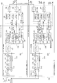
- FIG. 1 is a diagram illustrating a configuration example of a satellite positioning signal receiving device according to the first embodiment of the present technology.
- the satellite positioning signal receiving device is a receiving device that receives a satellite positioning signal in a satellite positioning system (GNSS).
- GNSS satellite positioning system
- different signal standards are assigned to a plurality of frequency bands (frequency bands).
- frequency bands such as L1 (1575.42 MHz), L2 (1222.70 MHz), and L5 (1176.45 MHz) are used.
- position accuracy can be improved by ionospheric delay correction. That is, since the ionospheric delay depends on the carrier frequency, the ionospheric delay can be estimated and corrected by observing signals of two or more frequencies, and the position error due to the ionosphere can be reduced.
- RTK and PPP are technologies that realize positioning with a very high accuracy of about several centimeters by using a carrier phase for distance measurement between a satellite and a receiver. Both have ambiguity problems due to the uncertainty of the integer part of the carrier phase.
- the determination of the integer part is called initialization, but the time required for this initialization can be greatly shortened by using observation values of two or more frequencies. For this reason, it is generally said that two or more frequencies are required for RTK and PPP.
- the satellite positioning signal receiving device in the first embodiment includes two GNSS receiving circuits.
- One is a GNSS receiving circuit 100 that functions as a master, and the other is a GNSS receiving circuit 200 that functions as a slave.
- the GNSS receiving circuits 100 and 200 each correspond to only one different frequency, and include an RF circuit 110 or 210 corresponding to one frequency and a digital signal processing unit 120 or 220.
- the satellite positioning signal receiving apparatus as a whole performs reception corresponding to the two frequencies L1 and L2 or the two frequencies L1 and L5.
- the GNSS receiving circuits 100 and 200 are both the same circuit, and only the internal operation differs depending on their roles.
- the internal configuration of the GNSS receiving circuit 100 will be mainly described, and the internal configuration of the GNSS receiving circuit 200 will be referred to as necessary.
- the GNSS receiving circuits 100 and 200 are examples of the satellite positioning signal receiving circuit described in the claims.
- the antenna 10 is an antenna that receives a satellite positioning signal. Satellite positioning signals received by the antenna 10 are input to RF circuits of GNSS receiving circuits 100 and 200 described later.
- the TCXO 20 is a temperature compensated crystal oscillator (TemperatureerCompensated Crystal Oscillator). The oscillation signal generated by the TCXO 20 is supplied to PLLs of GNSS receiving circuits 100 and 200 described later.
- the GNSS receiving circuit 100 includes an RF circuit 110 and a digital signal processing unit 120.
- the RF circuit 110 receives an RF (Radio Frequency) input from the antenna 10 and supplies it to the digital signal processing unit 120 as a digital signal.
- the digital signal processing unit 120 performs satellite acquisition, satellite tracking, and the like based on the digital signal supplied from the RF circuit 110.
- the RF circuit 110 is an example of the high-frequency processing unit described in the claims.
- the RF circuit 110 As the RF circuit 110, one corresponding to only one frequency in the L1 / L2 / L5 band is used. This simplifies the circuit configuration.
- the RF circuit 110 includes an LNA 111, a PLL 112, a MIX 113, an LPF 114, an AGC 115, and an ADC 116.
- the LNA 111 is an amplifier (LNA: Low Noise Amplifier) that amplifies the RF signal input from the antenna 10.
- the PLL 112 is a phase synchronization circuit (PLL: Phase : Locked Loop) that multiplies the reference frequency of the TCXO 20 to generate a local oscillation signal in the L1 / L2 / L5 band, an ADC clock, and a DSP clock.
- the local oscillation signal is supplied to the MIX 113, the ADC clock is supplied to the ADC 116, and the DSP clock is supplied to the digital signal processing unit 120.
- the MIX 113 is a mixer circuit that down-converts an amplified RF signal into an IF signal using the L1 / L2 / L5 band local oscillation signal supplied from the PLL 112.
- the LPF 114 is a low-pass filter (LPF: Low Pass Filter) that suppresses noise outside the signal band of interest for each of the IF signals in the L1 / L2 / L5 band.
- the AGC 115 is a circuit (AGC: Auto Gain Control) that adjusts the amplitude of the output of the LPF 114.
- the ADC 116 is an A / D converter (Analog-to-Digital Converter) that samples the output of the AGC 115 and converts the analog IF signal into a digital IF signal.
- the sampling clock of the ADC 116 is supplied from the PLL 112 as an ADC clock.
- the digital signal processing unit 120 includes a digital front end 121, a satellite processing unit 130, a positioning calculation unit 122, a PPS correction unit 123, a PPS counter 124, a receiver reference time counter 125, and serial interfaces 128 and 129.
- the digital front end 121 performs the previous stage processing on the L1 / L2 / L5 band digital IF signal input from the RF circuit 110. That is, the digital front end 121 performs down-conversion to a baseband signal, noise suppression outside the satellite signal band by a low-pass filter, and outputs a baseband signal in the L1 / L2 / L5 band.
- the satellite processing unit 130 is provided for each satellite, and captures, tracks, decodes navigation data, and observes satellites for any of the input L1 / L2 / L5 band baseband signals. The value is acquired.
- the satellite processing unit 130 is sequentially assigned with a satellite ID to be captured, and navigation data and satellite observation values of the satellite are acquired.
- a satellite processing unit corresponding to the number obtained by multiplying the number of satellites and the number of frequency bands is generally required. In this embodiment, the number of satellite processing units is limited to only one frequency. Can be reduced.
- Each of the satellite processing units 130 includes a satellite acquisition unit 131, a satellite tracking unit 132, a satellite observation value acquisition unit 133, and a navigation data decoder 134.
- the satellite acquisition unit 131 acquires the satellite signal based on the correlation detection between the input baseband signal and the satellite specific code sequence, and outputs the carrier frequency offset and the code phase that maximize the correlation value as the acquisition result. Is.
- the satellite tracking unit 132 mainly performs correlation processing with a satellite specific code, code timing synchronization, carrier wave synchronization, bit synchronization with respect to navigation data, and preamble synchronization, and reproduces the satellite time with the accuracy of the sampling period of the baseband signal. is there. A detailed configuration example of the satellite tracking unit 132 will be described later.
- the satellite observation value acquisition unit 133 acquires the satellite observation value output from the satellite tracking unit 132. This satellite observation value acquisition unit 133 acquires satellite observation values of all the satellite processing units output from the satellite tracking unit 132 according to the latch pulse supplied from the receiver reference time counter 125 at the same clock.
- the navigation data decoder 134 decodes the demodulated signal output from the satellite tracking unit 132 and synchronized with the satellite time into navigation data.
- the PPS counter 124 is a counter that counts the 1-second period synchronized with the GNSS time with the accuracy of the clock period.
- the PPS counter 124 outputs a rectangular pulse signal (1 PPS (Pulse Per Second)) with a period of 1 second to the outside. This 1PPS output is used in an external communication module or the like for time synchronization.
- the PPS counter 124 can be reset by an external reset input.
- the 1PPS output of the GNSS receiving circuit 100 is connected to the external reset of the PPS counter 224 of the GNSS receiving circuit 200 in addition to the output 108 to the outside. Therefore, the PPS counter 224 of the GNSS receiving circuit 200 is reset at the rising edge of 1PPS of the GNSS receiving circuit 100. Thereby, both PPS counters 124 and 224 are synchronized.
- both the GNSS receiving circuits 100 and 200 generate DSP clocks using the same TCXO 20 as a reference frequency, both clocks are synchronized with an accuracy of less than one clock. 224 is also synchronized with an accuracy of less than one clock.
- the PPS correction unit 123 corrects the 1 second period and the phase fluctuation of the PPS counter 124 caused by the TCXO frequency offset by using the time information and the TCXO frequency offset obtained by the above positioning calculation.
- the receiver reference time counter 125 is a counter that counts the reference time of the receiver (GNSS receiving circuit 100).
- the receiver reference time counter 125 self-runs endlessly at the cycle of the supplied clock after the supply of power and clock to the digital signal processing unit 120 is started.
- the receiver reference time counter 125 serves as a reference counter for processing timing and code phase detection in satellite acquisition and tracking, and is also used for pseudorange calculation.
- the receiver reference time counter 125 also generates a latch pulse that supplies timing when the satellite observation value acquisition unit 133 acquires the satellite observation value. Since the satellite observation value is used for positioning calculation every second, the latch pulse is generated with a fixed period of 1 second or less.
- the receiver reference time counter 125 is an example of a reference time counter described in the claims.
- the receiver reference time counters 125 and 225 of both the GNSS receiving circuits 100 and 200 can be reset only once after the power is turned on at the timing when the PPS counter 124 or 224 reaches a predetermined count, respectively. Since the receiver reference time counters 125 and 225 are free-running counters, once reset at the same time, the same count is continued thereafter. Therefore, both receiver reference times are synchronized with an accuracy of less than one clock, similar to the PPS counters 124 and 224.
- the acquisition timing of both satellite observation values is also synchronized, and the satellite observation values of two frequencies at the same time are acquired. be able to.
- the serial interface 129 outputs the time, position, and speed of the receiver obtained from the positioning calculation to an external host computer or communication module.
- the serial interface 129 is realized by a general UART (Universal Asynchronous Receiver / Transmitter), I2C (Inter-Integrated Circuit), or the like.
- the functions of the 1PPS output 108, the positioning calculation unit 122, the PPS correction unit 123, and the serial interface 129 are integrated into the master GNSS receiving circuit 100. Accordingly, the 1PPS output 208, the positioning calculation unit 222, the PPS correction unit 223, and the serial interface 229 of the slave GNSS receiving circuit 200 are invalidated.
- the shaded blocks and dotted signal lines in the figure indicate that their functions and signals are invalid and are not activated.
- the navigation data and satellite observation values of L2 / L5 of the GNSS receiving circuit 200 are transferred to the GNSS receiving circuit 100 via the serial interface 228.
- the GNSS receiving circuit 100 receives the L2 / L5 navigation data and the satellite observation value via the serial interface 128 different from the serial interface 129 that outputs the positioning result, and inputs the received data to the positioning calculation unit 122.
- the positioning calculation unit 122 performs positioning calculation using the navigation data obtained by the satellite processing unit 130 and the satellite observation value as input, and performs the time, position, speed, and frequency offset of the TCXO 20 of the receiver (GNSS receiving circuit 100). Is output.
- the positioning calculation unit 122 of the GNSS receiving circuit 100 performs positioning calculation using the navigation data and satellite observation values of L1 acquired by itself and the navigation data and satellite observation values of L2 / L5 transferred from the GNSS receiving circuit 200. Do. That is, the positioning calculation unit 122 is any one of single frequency positioning using any one of L1 / L2 / L5, two frequency positioning using L1 and L2, and two frequency positioning using L1 and L5. Perform positioning calculation.
- the receiver position (latitude, longitude, altitude) can be obtained by the principle of three-side survey if there are three or more satellite data based on the satellite position obtained from the navigation data and the pseudorange included in the satellite observation value. it can.
- the receiver time error is also unknown, so by solving simultaneous equations using data of four or more satellites, it is possible to simultaneously obtain the exact receiver time and receiver position synchronized with the GNSS time. .
- the receiver speed and the frequency offset of the TCXO 20 can be obtained by solving simultaneous equations using data of four or more satellites from the satellite speed obtained from the navigation data and the carrier frequency offset included in the satellite observation value. it can.
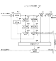
- FIG. 2 is a diagram illustrating a configuration example of the satellite tracking unit 132 according to the embodiment of the present technology.
- the satellite tracking unit 132 mainly performs correlation processing with a satellite specific code, code timing synchronization, carrier wave synchronization, bit synchronization with respect to navigation data, and preamble synchronization, and reproduces the satellite time with accuracy of the sampling period of the baseband signal.
- the pseudo-range calculator 660 estimates the propagation time of the satellite signal by taking a counter difference of one digit or less between the satellite time of the satellite time counter 650 and the receiver reference time of the receiver reference time counter 125.
- the propagation distance between the satellite and the receiver is estimated by multiplying the estimated propagation time of the satellite signal by the speed of light.
- the propagation distance estimated here is called a pseudorange because it includes an error due to the TCXO frequency offset of the receiver, circuit delay, an error due to the ionosphere, troposphere, multipath, and the like, compared to the actual geometric distance. These error factors are eliminated as much as possible by the above positioning calculation, and the receiver position is calculated.
- the demodulated signal synchronized with the satellite time is input to the navigation data decoder 134 at the subsequent stage, and the navigation data is decoded.
- Code timing synchronization is a process for synchronizing with the timing (phase) of spreading code modulation.
- This code timing synchronization is realized by a timing error detector 621, a code synchronization loop filter 622, a code synchronization NCO (NumericallyerControlled Oscillator) 623, a code generator 624, and a correlator 613.
- a timing error detector 621 a code synchronization loop filter 622
- a code synchronization NCO NumericallyerControlled Oscillator
- a code generator 624 a code generator 624
- the carrier wave synchronization is a process for synchronizing with the carrier wave (carrier).
- This carrier synchronization is realized by a carrier error detector (carrier frequency and phase error detector) 631, a carrier synchronization loop filter 632, a carrier synchronization NCO 633, and a multiplier 612 with a baseband signal.
- a carrier frequency offset of the satellite acquisition result as an initial value
- a feedback loop is formed so that the carrier error converges to zero, and the carrier is synchronized.
- the frequency offset and phase of the carrier wave are obtained, and the above-mentioned pseudo distance combined is output as a satellite observation value.
- Bit synchronization is performed by the bit synchronization unit 641.
- Preamble synchronization is performed by the preamble synchronization unit 642.
- two-frequency positioning can be realized by connecting the GNSS receiving circuits 100 and 200 corresponding to only one frequency.
- the receiving apparatus can be configured with only one single-frequency receiving circuit.
- a receiving device can be configured from two single-frequency receiving circuits. Thereby, it becomes possible to optimize circuit cost and power consumption more scalable for each application.
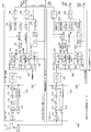
- FIG. 3 is a diagram illustrating a configuration example of the satellite positioning signal reception device according to the second embodiment of the present technology.
- This second embodiment differs from the first embodiment described above only in that the slave GNSS receiving circuit 200 is compatible with only one frequency of L1. That is, the satellite capturing unit 231 and the satellite tracking unit 232 support only one frequency of L1, and the navigation data and satellite observation values of L1 are transferred from the GNSS receiving circuit 200 to the GNSS receiving circuit 100.
- the GNSS receiving circuit 200 is configured to support only one frequency of L1, so that the entire satellite positioning signal receiving apparatus is further improved than the first embodiment described above. Circuit cost and power consumption can be reduced.
- the number of types of GNSS receiving circuits is increased as compared with the first embodiment described above, it is possible to increase options for applications that are sufficient with single-frequency positioning using only L1, which is currently most popular. Therefore, the circuit cost for each application and the power consumption scalability can be further improved.
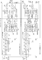
- FIG. 4 is a diagram illustrating a configuration example of a satellite positioning signal reception device according to the third embodiment of the present technology.
- the receiver reference time counters 125 and 225 can be directly synchronized without using the PPS counter 124 or 224. Only the difference.
- the external reset of the PPS counter 124 or 224 and the reset from the PPS counter 124 or 224 to the receiver reference time counter 125 or 225 are deleted. Instead, an external reset input and a reset output for the receiver reference time counters 125 and 225 are added. That is, the receiver reference time counters 125 and 225 are added with a function of outputting a reset signal only once at a predetermined count timing and a function of resetting its own counter with an external reset input as a trigger.
- the reset signal output from the receiver reference time counter 125 is input to the external reset of the receiver reference time counter 225.
- the receiver reference time counter 125 loops back the reset signal to its own external reset signal. As a result, the receiver reference time counters 125 and 225 are simultaneously reset, and both receiver reference times can be synchronized.
- the third embodiment is another form of the method of synchronizing the receiver times of both the GNSS receiving circuits 100 and 200.
- Other functions and effects realized are the same as those of the first embodiment. It is the same.
- FIG. 5 is a diagram illustrating a configuration example of a satellite positioning signal receiving device according to the fourth embodiment of the present technology.
- the fourth embodiment differs from the first embodiment described above in that the synchronization mechanism of the master / slave PPS counter triggered by 1PPS of the GNSS receiving circuit 100 is eliminated. Instead, the GNSS receiving circuit 200 also performs L2 / L5 positioning calculation to correct the PPS counter 224 of the GNSS receiving circuit 200 itself. As a result, the GNSS receiving circuits 100 and 200 synchronize the receiver reference time based on the respective PPS counters 124 or 224.
- FIG. 6 is a diagram illustrating a configuration example of a satellite positioning signal reception device according to the fifth embodiment of the present technology.
- This fifth embodiment differs from the fourth embodiment described above in that data transmission from the GNSS receiving circuit 200 to the GNSS receiving circuit 100 is performed wirelessly instead of wired. Therefore, in the fifth embodiment, the wireless interface 126 or 226 and the wireless transmission antenna 31 or 32 are added to the end of the serial interface 128 or 228.
- the wiring between the master and the slave can be further reduced, and the flexibility of the layout of the GNSS receiving circuits 100 and 200 can be increased.
- FIG. 7 is a diagram illustrating a configuration example of a satellite positioning signal receiving device according to the sixth embodiment of the present technology.
- the satellite processing unit 130 the satellite capturing unit 131 is compatible only with L1.
- a frequency / delay correction unit 235 is added.
- the receiver reference time (latch time) at which the satellite observation value acquisition unit 133 acquires the satellite observation value is also held.
- the L1 satellite observation value and the latch time acquired by the GNSS receiving circuit 100 are transferred to the GNSS receiving circuit 200 via the serial interfaces 128 and 228.
- a method is known in which the L2 and L5 transmission frames are synchronized with the L1 transmission frame, and the L2 and L5 satellite acquisition is performed using the L1 satellite tracking result. If such a method is used, it is not necessary to deal with satellite acquisition alone for L2 where the code sequence length is 10 times that of L1 and L5 where the code sequence length and code band is 10 times. It is possible to avoid an increase in the circuit size and power consumption of satellite acquisition due to L5.
- the sixth embodiment is an example that enables L2 / L5 satellite capture using such L1 assist.
- the L1 satellite observation value and the latch time acquired by the GNSS receiver circuit 100 are input to the frequency / delay correction unit 235 of the GNSS receiver circuit 200, and the difference between the carrier frequencies of L1 and L2 / L5 and the elapsed time from the latch time are calculated. Satellite observation values are taken into account. Since the L2 / L5 satellite acquisition information (carrier frequency offset and code phase) can be predicted from the corrected satellite observation value, the L2 / L5 satellite tracking can be performed using the predicted value.
- satellite observation values are corrected by the following procedure, and L2 / L5 satellite capture information is predicted.
- the carrier frequency of L1 is included in f L1
- the carrier frequency of L2 / L5 is included in f Lx
- the satellite observation value is included.
- the carrier frequency offset of L1 is ⁇ f L1
- the L1 bit boundary and subframe boundary can be obtained by restoring the satellite time at the time of latching from the pseudo-range included in the satellite observation value.
- the predicted value of the L2 / L5 code phase can be obtained by advancing the phase of the L2 / L5 transmission frame synchronized with this by the elapsed time.
- the L2 / L5 satellite tracking can be performed using the L1 satellite observation value, the satellite by supporting the L2 / L5 single acquisition is used. An increase in the circuit scale of acquisition can be avoided, and the circuit cost can be further reduced.
- FIG. 8 is a diagram illustrating a configuration example of a satellite positioning signal reception device according to the seventh embodiment of the present technology.
- the seventh embodiment differs from the first embodiment described above in that the antenna 11 of the GNSS receiving circuit 100 and the antenna 12 of the GNSS receiving circuit 200 are provided separately.
- GNSS receiving circuits 100 and 200 capture and track satellite signals in the same frequency band of L1 / L2 / L5 from different antennas 11 and 12, and select satellite observation values with better demodulation quality from both. And used for positioning calculation. Thereby, more stable single frequency positioning performance can be realized.
- the GNSS compass is a carrier positioning technique that applies the principle of RTK, whereby the direction of the baseline vector can be obtained with high accuracy.
- FIG. 9 is a diagram illustrating a configuration example of a satellite positioning signal reception device according to the eighth embodiment of the present technology.
- one frequency GNSS receiving circuit 300 is added as a second slave in order to support three frequencies. Different. Another difference is that another serial interface 127 is added to the GNSS receiving circuit 100 so that data from the GNSS receiving circuit 300 can also be received.
- L1 is assigned to the GNSS receiver circuit 100 (master)
- L2 is assigned to the GNSS receiver circuit 200 (first slave)
- L5 is assigned to the GNSS receiver circuit 300 (second slave). ing.
- the GNSS receiving circuit 100 can also synchronize with the GNSS receiving circuit 300 by connecting 1 PPS to the GNSS receiving circuit 300 as an external reset.
- the GNSS receiving circuit 100 also acquires the navigation data and satellite observation values of L1 acquired by itself, the navigation data and satellite observation values of L2 transmitted from the GNSS receiving circuit 200, and the L5 navigation data and satellite observation values transmitted from the GNSS receiving circuit 300. Use navigation data and satellite observations.
- the positioning calculation unit 122 can also perform positioning calculation using three frequencies of L1 / L2 / L5.
- the effect of frequency diversity can be further enhanced than 2 frequencies, and resistance to interference can be improved and more stable positioning performance can be realized.
- the initialization time can be further advanced compared to the two frequencies.
- FIG. 10 is a diagram illustrating a configuration example of the satellite positioning signal reception device according to the ninth embodiment of the present technology.
- the GNSS receiving circuit is only the master (only the GNSS receiving circuit 100) and the interface between the master and the slave is deleted as compared with the first embodiment described above. Since no synchronization between the master and the slave is necessary, a reset signal from the PPS counter 124 to the receiver reference time counter 125 is not provided.
- a PLL 118 for generating an ADC clock and a DSP clock is provided independently of a PLL 117 for generating an L1 / L2 / L5 band local oscillation signal.
- the satellite positioning signal receiving apparatus switches the acquisition and tracking of the L1 satellite and the L2 / L5 satellite sequentially.
- PLLs 117 and 118 are provided independently corresponding to the generation of the local oscillation signal and the generation of the clock, respectively, thereby maintaining the continuity of synchronization with the digital clock regardless of the switching of the local oscillation frequency. Can do.
- the PLL 117 is an example of a first phase synchronization circuit described in the claims.
- the PLL 118 is an example of a second phase synchronization circuit described in the claims.
- the digital signal processing unit 120 first captures and tracks the L1 satellite, and then generates an L2 / L5 capture prediction value using the satellite observation value and the latch time. Next, the local oscillation frequency of the RF circuit 110 is switched to L2 / L5, and then the L2 / L5 satellite tracking is started using the previously generated predicted value.
- one or a plurality of GNSS receiving circuits corresponding to only one frequency are provided, and a synchronization control interface for synchronizing each receiving circuit and a satellite between each receiving circuit.
- a transmission interface is provided for sharing observation information.
- a satellite positioning signal receiving device including at least one satellite positioning signal receiving circuit that receives satellite positioning signals corresponding to a single frequency band and generates satellite observation information, Each of the satellite positioning signal receiving circuits includes a synchronization control interface for synchronizing between the satellite positioning signal receiving circuits, and a satellite information transmission interface for sharing the satellite observation information between the satellite positioning signal receiving circuits. And A satellite positioning signal receiving device that performs positioning based on the satellite observation information.
- the synchronization control interface includes an output signal of a rectangular pulse signal with a period of 1 second and an external reset input signal that resets a pulse counter that generates the rectangular pulse signal, Each of the satellite positioning signal receiving circuits resets the pulse counter based on the external reset input signal, and sets a reference time counter for counting a reference time of the satellite positioning signal receiving circuit based on the count time of the pulse counter.
- the satellite positioning signal receiving device according to (1), which is reset.
- the synchronization control interface includes a reset output signal of a reference time counter that counts a reference time of the satellite positioning signal receiving circuit, and an external reset input signal for the reference time counter, Each of the satellite positioning signal reception circuits resets the reference time counter based on the external reset input signal, and outputs the reset output signal based on the count time of the reference time counter. Satellite positioning signal receiver. (4) Each of the satellite positioning signal receiving circuits sets the reference time of the satellite positioning signal receiving circuit based on the count time of a pulse counter that generates a rectangular pulse signal with a period of 1 second instead of the synchronization control interface.
- the satellite positioning signal receiving device according to (1), wherein the reference time counter for counting is reset to synchronize with the time accuracy of the rectangular pulse signal.
- a satellite positioning signal receiving circuit that receives a signal other than the first frequency band uses satellite observation information obtained from the satellite positioning signal receiving circuit that receives the first frequency band.
- each of the satellite positioning signal receiving circuits includes an antenna independently.
- a satellite positioning signal receiving device including first and second satellite positioning signal receiving circuits, Each of the first and second satellite positioning signal receiving circuits includes a high-frequency processing unit that converts a high-frequency signal into a digital signal corresponding to a single frequency band, a reference time counter that counts a reference time, and the reference A digital signal processing unit that performs satellite acquisition and satellite tracking based on the digital signal according to time, The reference time counters of the first and second satellite positioning signal receiving circuits count the reference time in synchronization with each other, The second satellite positioning signal receiving circuit acquires satellite observation information of a second frequency band different from the first satellite positioning signal receiving circuit and supplies the satellite observation information to the first satellite positioning signal receiving circuit; The first satellite positioning signal receiving circuit acquires satellite observation information in a first frequency band different from that of the second satellite positioning signal receiving circuit, and is supplied from the second satellite positioning signal receiving circuit.
- a satellite positioning signal receiving apparatus that performs positioning using satellite observation information of a plurality of frequency bands together with satellite observation information of the second frequency band.
- the satellite positioning signal receiving device according to (10), wherein the digital signal processing unit of the second satellite positioning signal receiving circuit has a circuit configuration corresponding to only the second frequency band.
- Each of the first and second satellite positioning signal receiving circuits further includes a pulse counter that outputs a rectangular pulse signal having a period of 1 second to the outside, The pulse counter of the second satellite positioning signal receiving circuit is reset by the pulse counter of the first satellite positioning signal receiving circuit;
- the reference time counters of the first and second satellite positioning signal receiving circuits are synchronized with each other by resetting the reference time counter according to the pulse counter in each of the first and second satellite positioning signal receiving circuits.
- the satellite positioning signal receiver according to (10) above. (13)
- the reference time counter of the first satellite positioning signal receiving circuit outputs a reference time reset signal for resetting the reference time
- the reference time counter of the first and second satellite positioning signal receiving circuits resets the reference time counter according to the reference time reset signal, whereby the reference time of the first and second satellite positioning signal receiving circuits is reset.
- the satellite positioning signal receiver according to (10), wherein the counters are synchronized with each other.
- Each of the first and second satellite positioning signal receiving circuits further includes a pulse counter that outputs a rectangular pulse signal having a period of 1 second to the outside,
- the digital signal processing unit of the second satellite positioning signal receiving circuit performs positioning using the satellite observation information of the second frequency band,
- the pulse counter of the second satellite positioning signal receiving circuit is corrected based on a positioning result using satellite observation information of the second frequency band,
- the reference time counters of the first and second satellite positioning signal receiving circuits are synchronized with each other by resetting the reference time counter according to the pulse counter in each of the first and second satellite positioning signal receiving circuits.
- the satellite positioning signal receiver according to (10) above.
- Each of the first and second satellite positioning signal receiving circuits transmits satellite observation information of the second frequency band from the second satellite positioning signal receiving circuit to the first satellite positioning signal receiving circuit.
- the satellite positioning signal receiving apparatus according to any one of (10) to (14), further including a wireless interface to be supplied.
- the first satellite positioning signal receiving circuit supplies satellite observation information of the first frequency band to the second satellite positioning signal receiving circuit
- the second satellite positioning signal receiving circuit includes a satellite observation value correcting unit that corrects the satellite observation information of the first frequency band supplied from the first satellite positioning signal receiving circuit, and based on the correction result.
- the satellite positioning signal receiver according to (10), which performs satellite tracking in the second frequency band.
- each of the first and second satellite positioning signal receiving circuits includes an antenna that supplies a high-frequency signal to the high-frequency processing unit.
- the reference time counters of the first and third satellite positioning signal receiving circuits count the reference time in synchronization with each other,
- the third satellite positioning signal receiving circuit acquires satellite observation information of a third frequency band different from the first satellite positioning signal receiving circuit, and supplies the satellite observation information to the first satellite positioning signal receiving circuit;
- the first satellite positioning signal receiving circuit performs positioning using satellite observation information of a plurality of frequency bands together with satellite observation information of the third frequency band supplied from the third satellite positioning signal receiving circuit.
- the satellite positioning signal receiving apparatus which is performed.
- a high-frequency processing unit that converts a high-frequency signal into a digital signal corresponding to a single frequency band
- a digital signal processing unit that performs satellite acquisition and satellite tracking based on the digital signal according to a reference time
- a first phase synchronization circuit for sequentially supplying local oscillator signals of different frequency bands to the high-frequency processing unit
- Satellite positioning signal reception comprising an analog / digital converter of the high-frequency processing unit and a second phase synchronization circuit for supplying a clock signal to the digital signal processing unit independently of the first phase synchronization circuit apparatus.
Landscapes
- Engineering & Computer Science (AREA)
- Radar, Positioning & Navigation (AREA)
- Remote Sensing (AREA)
- Computer Networks & Wireless Communication (AREA)
- Signal Processing (AREA)
- Physics & Mathematics (AREA)
- General Physics & Mathematics (AREA)
- Position Fixing By Use Of Radio Waves (AREA)
- Synchronisation In Digital Transmission Systems (AREA)
Abstract
複数の周波数帯の衛星観測情報を用いて測位を行う衛星測位信号受信装置において、必要な周波数帯に応じて段階的に増設可能にする。 衛星測位信号受信装置は、単一の周波数帯に対応して衛星測位信号を受信して衛星観測情報を生成する衛星測位信号受信回路を少なくとも1つ具備する。衛星測位信号受信回路の各々は、衛星測位信号受信回路の間で同期させるための同期制御インターフェースと、衛星測位信号受信回路の間で前記衛星観測情報を共有するための衛星情報伝送インターフェースとを備える。衛星測位信号受信装置は、衛星観測情報に基づいて測位を行う。
Description
本技術は、衛星測位信号受信装置に関する。詳しくは、複数の周波数帯の衛星観測情報を用いて測位を行う衛星測位信号受信装置に関する。
米国のGPS(Global Positioning System)に代表される衛星測位システムは、今日、カーナビやスマートホン等に広く普及し、日常生活において、位置情報はより欠かせないものになってきている。米国のGPS以外にも日本のQZSS、ロシアのGLONASS、中国のBeiDou、欧州のGalileoなど、世界各国において、独自の衛星測位システムが規格化され、運用されている。それらの衛星測位システムは、GNSS(Global Navigation Satellite System)と総称される。
このような衛星測位システムにおける衛星測位信号を受信する受信装置(GNSS受信装置または衛星測位信号受信装置)は、単一の周波数帯のみに対応するものが普及しているが、2周波以上の周波数帯に対応できると様々な利点が得られる。例えば、2つの周波数帯の航法信号を受信して、複数の周波数で測定した各疑似距離に基づいて疑似距離真値を得る衛星航法装置が提案されている(例えば、特許文献1参照。)。
上述の従来技術では、複数の周波数で疑似距離を測定することにより、疑似距離真値に混入する雑音成分を低減している。しかしながら、この従来技術では、複数の周波数帯についてそれぞれ独立にRF回路(高周波回路)を設けており、同じ受信装置内で複数の周波数帯に対応した衛星捕捉および追尾回路を複数チャネル分、設けている。そのため、周波数帯の数に応じてRF回路が増え、また、受信する衛星信号の数が増える分、衛星処理ユニットの数も増えてしまうという問題がある。さらに、衛星捕捉や衛星追尾、航法データ復号も新たな近代化GNSS信号に対応する必要があるため、衛星処理ユニットそのものの回路規模も大幅に増えてしまい、今後の多周波対応が困難になるという問題がある。
本技術はこのような状況に鑑みて生み出されたものであり、複数の周波数帯の衛星観測情報を用いて測位を行う衛星測位信号受信装置において、必要な周波数帯に応じて段階的に増設可能にすることを目的とする。
本技術は、上述の問題点を解消するためになされたものであり、その第1の側面は、単一の周波数帯に対応して衛星測位信号を受信して衛星観測情報を生成する衛星測位信号受信回路を少なくとも1つ具備する衛星測位信号受信装置であって、上記衛星測位信号受信回路の各々は、上記衛星測位信号受信回路の間で同期させるための同期制御インターフェースと、上記衛星測位信号受信回路の間で上記衛星観測情報を共有するための衛星情報伝送インターフェースとを備え、上記衛星観測情報に基づいて測位を行う衛星測位信号受信装置である。これにより、衛星測位信号受信回路の間で同期させて、衛星観測情報を共有するという作用をもたらす。
また、この第1の側面において、上記同期制御インターフェースは、1秒周期の矩形パルス信号の出力信号と、上記矩形パルス信号を生成するパルスカウンタをリセットする外部リセット入力信号を備え、上記衛星測位信号受信回路の各々は、上記外部リセット入力信号に基づいて上記パルスカウンタをリセットし、上記衛星測位信号受信回路の基準時刻を計数する基準時刻カウンタを上記パルスカウンタのカウント時刻に基づいてリセットするようにしてもよい。これにより、パルスカウンタのカウント時刻に基づいて基準時刻カウンタをリセットするという作用をもたらす。
また、この第1の側面において、上記同期制御インターフェースは、上記衛星測位信号受信回路の基準時刻を計数する基準時刻カウンタのリセット出力信号と、上記基準時刻カウンタに対する外部リセット入力信号を備え、上記衛星測位信号受信回路の各々は、上記外部リセット入力信号に基づいて上記基準時刻カウンタをリセットし、上記基準時刻カウンタのカウント時刻に基づいて上記リセット出力信号を出力するようにしてもよい。これにより、外部リセット入力信号に基づいて基準時刻カウンタをリセットするという作用をもたらす。
また、この第1の側面において、上記衛星測位信号受信回路の各々は、上記同期制御インターフェースに代えて、1秒周期の矩形パルス信号を生成するパルスカウンタのカウント時刻に基づいて、上記衛星測位信号受信回路の基準時刻を計数する基準時刻カウンタをリセットすることにより、上記矩形パルス信号の時刻精度で同期させるようにしてもよい。これにより、同期制御インターフェースを設けることなく矩形パルス信号の時刻精度で同期させるという作用をもたらす。
また、この第1の側面において、上記衛星情報伝送インターフェースは有線インターフェースであってもよい。また、この場合において、上記衛星情報伝送インターフェースは有線のシリアルインターフェースであってもよい。また、上記衛星情報伝送インターフェースは無線インターフェースであってもよい。
また、この第1の側面において、上記衛星測位信号受信回路のうち第1の周波数帯以外を受信する衛星測位信号受信回路は、上記第1の周波数帯を受信する衛星測位信号受信回路から得られる衛星観測情報を用いて衛星捕捉を行うようにしてもよい。これにより、他の衛星測位信号受信回路から得られる衛星観測情報を用いて衛星捕捉を行うという作用をもたらす。
また、この第1の側面において、上記衛星測位信号受信回路の各々は、それぞれ独立にアンテナを備えるようにしてもよい。これにより、ダイバーシティ効果やGNSSコンパスを実現するという作用をもたらす。
また、本技術の第2の側面は、第1および第2の衛星測位信号受信回路を具備する衛星測位信号受信装置であって、上記第1および第2の衛星測位信号受信回路の各々は、単一の周波数帯に対応して高周波信号をデジタル信号に変換する高周波処理部と、基準時刻を計数する基準時刻カウンタと、上記基準時刻に従って上記デジタル信号に基づいて衛星捕捉および衛星追尾を行うデジタル信号処理部とを備え、上記第1および第2の衛星測位信号受信回路の上記基準時刻カウンタは、互いに同期して上記基準時刻を計数し、上記第2の衛星測位信号受信回路は、上記第1の衛星測位信号受信回路とは異なる第2の周波数帯の衛星観測情報を取得して上記第1の衛星測位信号受信回路に供給し、上記第1の衛星測位信号受信回路は、上記第2の衛星測位信号受信回路とは異なる第1の周波数帯の衛星観測情報を取得して、上記第2の衛星測位信号受信回路から供給された上記第2の周波数帯の衛星観測情報と併せて複数の周波数帯の衛星観測情報を用いた測位を行う衛星測位信号受信装置である。これにより、複数の衛星測位信号受信回路によって取得された複数の衛星観測情報を用いた測位を行うという作用をもたらす。
また、この第2の側面において、上記第2の衛星測位信号受信回路のデジタル信号処理部は、上記第2の周波数帯のみに対応した回路構成であってもよい。これにより、第2の衛星測位信号受信回路を簡易化させるという作用をもたらす。
また、この第2の側面において、上記第1および第2の衛星測位信号受信回路の各々は、1秒周期の矩形パルス信号を外部に出力するパルスカウンタをさらに備え、上記第2の衛星測位信号受信回路の上記パルスカウンタは、上記第1の衛星測位信号受信回路の上記パルスカウンタによりリセットされ、上記第1および第2の衛星測位信号受信回路の各々において上記パルスカウンタに従って上記基準時刻カウンタをリセットすることにより、上記第1および第2の衛星測位信号受信回路の上記基準時刻カウンタを互いに同期させるようにしてもよい。
また、この第2の側面において、上記第1の衛星測位信号受信回路の上記基準時刻カウンタは、上記基準時刻をリセットする基準時刻リセット信号を出力し、上記第1および第2の衛星測位信号受信回路の上記基準時刻カウンタが上記基準時刻リセット信号に従って上記基準時刻カウンタをリセットすることにより、上記第1および第2の衛星測位信号受信回路の上記基準時刻カウンタを互いに同期させるようにしてもよい。
また、この第2の側面において、上記第1および第2の衛星測位信号受信回路の各々は、1秒周期の矩形パルス信号を外部に出力するパルスカウンタをさらに備え、上記第2の衛星測位信号受信回路のデジタル信号処理部は、上記第2の周波数帯の衛星観測情報を用いて測位を行い、上記第2の衛星測位信号受信回路の上記パルスカウンタは、上記第2の周波数帯の衛星観測情報を用いた測位結果に基づいて補正され、上記第1および第2の衛星測位信号受信回路の各々において上記パルスカウンタに従って上記基準時刻カウンタをリセットすることにより、上記第1および第2の衛星測位信号受信回路の上記基準時刻カウンタを互いに同期させるようにしてもよい。
また、この第2の側面において、上記第1および第2の衛星測位信号受信回路の各々は、上記第2の衛星測位信号受信回路から上記第1の衛星測位信号受信回路に上記第2の周波数帯の衛星観測情報を供給する無線インターフェースを備えるようにしてもよい。これにより、第1および第2の衛星測位信号受信回路の間の配線を減らすという作用をもたらす。
また、この第2の側面において、上記第1の衛星測位信号受信回路は、上記第1の周波数帯の衛星観測情報を上記第2の衛星測位信号受信回路に供給し、上記第2の衛星測位信号受信回路は、上記第1の衛星測位信号受信回路から供給された上記第1の周波数帯の衛星観測情報を補正する衛星観測値補正部を備え、この補正結果に基づいて上記第2の周波数帯の衛星追尾を行うようにしてもよい。これにより、衛星捕捉に要する回路を簡易化させるという作用をもたらす。
また、この第2の側面において、上記第1および第2の衛星測位信号受信回路の各々は、上記高周波処理部に高周波信号を供給するアンテナをそれぞれ備えてもよい。これにより、第1および第2の衛星測位信号受信回路のアンテナを独立させて、ダイバーシティ効果やGNSSコンパスを実現するという作用をもたらす。
また、この第2の側面において、上記高周波処理部と、上記基準時刻カウンタと、上記デジタル信号処理部とを備える第3の衛星測位信号受信回路をさらに具備し、上記第1および第3の衛星測位信号受信回路の上記基準時刻カウンタは、互いに同期して上記基準時刻を計数し、上記第3の衛星測位信号受信回路は、上記第1の衛星測位信号受信回路とは異なる第3の周波数帯の衛星観測情報を取得して上記第1の衛星測位信号受信回路に供給し、上記第1の衛星測位信号受信回路は、上記第3の衛星測位信号受信回路から供給された上記第3の周波数帯の衛星観測情報と併せて複数の周波数帯の衛星観測情報を用いた測位を行うようにしてもよい。これにより、同時に取得される衛星観測情報をさらに増やすという作用をもたらす。
また、本技術の第3の側面は、単一の周波数帯に対応して高周波信号をデジタル信号に変換する高周波処理部と、基準時刻に従って上記デジタル信号に基づいて衛星捕捉および衛星追尾を行うデジタル信号処理部と、上記高周波処理部に対して順次異なる周波数帯の局部発振器信号を供給する第1の位相同期回路と、上記第1の位相同期回路とは独立して上記高周波処理部のアナログ/デジタル変換器および上記デジタル信号処理部に対してクロック信号を供給する第2の位相同期回路とを具備する衛星測位信号受信装置である。これにより、単一の周波数帯に対応する高周波処理部およびデジタル信号処理部の周波数帯を順次切り替えて複数の周波数帯の衛星観測情報を取得するという作用をもたらす。
本技術によれば、複数の周波数帯の衛星観測情報を用いて測位を行う衛星測位信号受信装置において、必要な周波数帯に応じて段階的に増設可能にすることができるという優れた効果を奏し得る。これにより、アプリケーション毎に回路コストや消費電力を最適化することが可能となる。なお、ここに記載された効果は必ずしも限定されるものではなく、本開示中に記載されたいずれかの効果であってもよい。
以下、本技術を実施するための形態(以下、実施の形態と称する)について説明する。説明は以下の順序により行う。
1.第1の実施の形態(PPSカウンタによって受信機基準時刻カウンタをリセットする例)
2.第2の実施の形態(スレーブをL1専用にした例)
3.第3の実施の形態(受信機基準時刻カウンタが直接リセットされる例)
4.第4の実施の形態(スレーブでも測位計算を行ってスレーブ自身のPPSカウンタを補正する例)
5.第5の実施の形態(スレーブからマスターへのデータ伝送を無線で行う例)
6.第6の実施の形態(衛星捕捉をL1についてのみ行い、L2とL5については予測する例)
7.第7の実施の形態(ダイバシティアンテナまたはGNSSコンパスの例)
8.第8の実施の形態(3周波対応の例)
9.第9の実施の形態(スレーブを削除した例)
1.第1の実施の形態(PPSカウンタによって受信機基準時刻カウンタをリセットする例)
2.第2の実施の形態(スレーブをL1専用にした例)
3.第3の実施の形態(受信機基準時刻カウンタが直接リセットされる例)
4.第4の実施の形態(スレーブでも測位計算を行ってスレーブ自身のPPSカウンタを補正する例)
5.第5の実施の形態(スレーブからマスターへのデータ伝送を無線で行う例)
6.第6の実施の形態(衛星捕捉をL1についてのみ行い、L2とL5については予測する例)
7.第7の実施の形態(ダイバシティアンテナまたはGNSSコンパスの例)
8.第8の実施の形態(3周波対応の例)
9.第9の実施の形態(スレーブを削除した例)
<1.第1の実施の形態>
[衛星測位信号受信装置の構成]
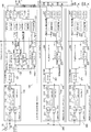
図1は、本技術の第1の実施の形態における衛星測位信号受信装置の構成例を示す図である。
[衛星測位信号受信装置の構成]
図1は、本技術の第1の実施の形態における衛星測位信号受信装置の構成例を示す図である。
衛星測位信号受信装置は、衛星測位システム(GNSS)における衛星測位信号を受信する受信装置である。GNSSでは、複数の周波数帯(周波数バンド)に異なる信号規格が割り当てられている。例えば、GPSでは、L1(1575.42MHz)、L2(1227.60MHz)、L5(1176.45MHz)等の周波数帯が用いられている。これら2周波以上の周波数帯に対応した場合、以下のような利点が得られる。
第1に、電離層遅延補正による位置精度改善が得られる。すなわち、電離層遅延は搬送波周波数に依存するため、2周波以上の信号観測により、電離層遅延の推定と補正が可能となり、電離層に起因する位置誤差を低減できる。
第2に、RTK(Real Time Kinematic)やPPP(Precise Point Positioning)の初期化時間短縮が得られる。RTKおよびPPPは、衛星/受信機間の測距に搬送波位相を用いることにより数センチメートル程度の非常に高精度な測位を実現する技術である。いずれも搬送波位相の整数部の不確定性に起因するアンビギュイティの課題がある。整数部を確定させることを初期化というが、2周波以上の観測値を用いることにより、この初期化に要する時間を大幅に短縮することができる。このため、一般的にRTKやPPPでは2周波以上が必要と言われている。
第3に妨害耐性の向上が得られる。すなわち、周波数ダイバーシティの効果により、機器内および機器外の双方より発生する干渉波や意図的な妨害波に対する耐性が向上する。
第4に、近代化GNSS信号による位置精度、マルチパス耐性、感度の向上が得られる。今後、数年のうちに対応する衛星が整備されて、サービス運用が本格化する予定のL5/E5の周波数バンドは、近代化GNSSとも呼ばれ、チップレートの広帯域化やパイロットチャネルの導入により、位置精度の改善やマルチパス耐性の向上、受信感度の向上が見込める。
そのため、本技術の実施の形態においては、複数の周波数帯の衛星観測情報を用いて測位を行うことを想定する。この第1の実施の形態における衛星測位信号受信装置は、2台のGNSS受信回路を備える。一方はマスターとして機能するGNSS受信回路100であり、他方はスレーブとして機能するGNSS受信回路200である。GNSS受信回路100および200はそれぞれ異なる1周波のみに対応し、1周波対応のRF回路110または210と、デジタル信号処理部120または220とを備える。衛星測位信号受信装置全体として、L1とL2の2周波、または、L1とL5の2周波に対応した受信を行う。GNSS受信回路100および200はどちらも同じ回路であり、その役割によって、内部の動作のみが異なる。したがって、以下では主にGNSS受信回路100の内部構成について説明し、必要に応じてGNSS受信回路200の内部構成についても言及する。なお、GNSS受信回路100および200は、特許請求の範囲に記載の衛星測位信号受信回路の一例である。
これらGNSS受信回路100および200は、アンテナ10およびTCXO20を共有する。アンテナ10は、衛星測位信号を受信するアンテナである。このアンテナ10によって受信された衛星測位信号は、後述するGNSS受信回路100および200のRF回路に入力される。TCXO20は、温度補償型水晶発振器(Temperature Compensated Crystal Oscillator)である。このTCXO20による発振信号は、後述するGNSS受信回路100および200のPLLに供給される。
GNSS受信回路100は、RF回路110と、デジタル信号処理部120とを備える。RF回路110は、アンテナ10から入力されるRF(Radio Frequency:高周波)信号を受信して、デジタル信号としてデジタル信号処理部120に供給するものである。デジタル信号処理部120は、RF回路110から供給されたデジタル信号に基づいて衛星捕捉および衛星追尾などを行うものである。なお、RF回路110は、特許請求の範囲に記載の高周波処理部の一例である。
RF回路110としてはL1/L2/L5帯のいずれか1周波のみに対応するものを用いる。これにより、回路構成の簡易化を図る。このRF回路110は、LNA111と、PLL112と、MIX113と、LPF114と、AGC115と、ADC116とを備える。
LNA111は、アンテナ10から入力されるRF信号を増幅する増幅器(LNA:Low Noise Amplifier)である。PLL112は、TCXO20の基準周波数を逓倍して、L1/L2/L5帯の局部発振信号、ADCクロック、および、DSPクロックを生成する位相同期回路(PLL:Phase Locked Loop)である。局部発振信号はMIX113に供給され、ADCクロックはADC116に供給され、DSPクロックはデジタル信号処理部120に供給される。
MIX113は、PLL112から供給されたL1/L2/L5帯の局部発振信号を用いて、増幅されたRF信号をIF信号にダウンコンバージョンするミキサー回路である。LPF114は、L1/L2/L5帯のIF信号に対してそれぞれ、着目信号帯域外の雑音を抑圧するローパスフィルタ(LPF:Low Pass Filter)である。AGC115は、LPF114の出力を振幅調整する回路(AGC:Auto Gain Control)である。
ADC116は、AGC115の出力をサンプリングしてアナログIF信号からデジタルIF信号に変換するA/D変換器(Analog-to-Digital Converter)である。このADC116のサンプリングクロックは、PLL112からADCクロックとして供給される。
デジタル信号処理部120は、デジタルフロントエンド121、衛星処理ユニット130、測位計算部122、PPS補正部123、PPSカウンタ124、受信機基準時刻カウンタ125、シリアルインターフェース128および129を備える。
デジタルフロントエンド121は、RF回路110から入力されるL1/L2/L5帯のデジタルIF信号に対する前段の処理を行うものである。すなわち、このデジタルフロントエンド121は、ベースバンド信号へのダウンコンバージョン、ローパスフィルタによる衛星信号帯域外の雑音抑圧を行い、L1/L2/L5帯のベースバンド信号を出力する。
衛星処理ユニット130は、1衛星単位に設けられ、入力されるL1/L2/L5帯のベースバンド信号のうちいずれかの信号に対して、衛星信号の捕捉、追尾、航法データの復号、衛星観測値の取得を行うものである。この衛星処理ユニット130に対しては、順次、捕捉対象の衛星IDが割り当てられ、その衛星の航法データや衛星観測値が取得される。従来技術においては一般に衛星数と周波数帯の数とを乗算した数に相当する衛星処理ユニットが必要になるが、この実施の形態においては、1周波のみに限定することにより、衛星処理ユニットの数を削減することができる。この衛星処理ユニット130の各々は、衛星捕捉部131と、衛星追尾部132と、衛星観測値取得部133と、航法データ復号器134とを備える。
衛星捕捉部131は、入力されるベースバンド信号と衛星固有コード系列との相関検出に基づいて衛星信号の捕捉を行い、捕捉結果として、相関値が最大となる搬送波周波数オフセットおよびコード位相を出力するものである。
衛星追尾部132は、主に衛星固有コードとの相関処理、コードタイミング同期、搬送波同期、航法データに対するビット同期、プリアンブル同期を行い、衛星時刻をベースバンド信号のサンプリング周期の精度で再生するものである。この衛星追尾部132の詳細構成例については後述する。
衛星観測値取得部133は、衛星追尾部132から出力された衛星観測値を取得するものである。この衛星観測値取得部133は、受信機基準時刻カウンタ125から供給されるラッチパルスに従って衛星追尾部132から出力される全衛星処理ユニットの衛星観測値を同一クロックで一斉に取得する。
航法データ復号器134は、衛星追尾部132から出力された、衛星時刻との同期がとれた復調信号を、航法データに復号するものである。
PPSカウンタ124は、GNSS時刻に同期した1秒の周期をクロック周期の精度でカウントするカウンタである。このPPSカウンタ124は、1秒周期の矩形パルス信号(1PPS(Pulse Per Second))を外部に出力する。この1PPSの出力は、時刻同期のために、外部の通信モジュール等において使用される。また、このPPSカウンタ124は、外部リセット入力によりリセットすることができるようになっている。
GNSS受信回路100の1PPS出力は、外部への出力108に加えて、GNSS受信回路200のPPSカウンタ224の外部リセットにも接続されている。したがって、GNSS受信回路200のPPSカウンタ224は、GNSS受信回路100の1PPSの立ち上がりでリセットされる。これにより、双方のPPSカウンタ124および224は同期化される。
上述のように、GNSS受信回路100および200は、ともに同一のTCXO20を基準周波数としてDSPクロックが生成されるため、両者のクロックは1クロック未満の精度で同期しており、両者のPPSカウンタ124および224も1クロック未満の精度で同期化される。
PPS補正部123は、上述の測位計算によって得られた時刻情報やTCXO周波数オフセットを用いて、TCXO周波数オフセットに起因するPPSカウンタ124の1秒周期や位相のゆらぎを補正するものである。
受信機基準時刻カウンタ125は、受信機(GNSS受信回路100)の基準時刻を計数するカウンタである。この受信機基準時刻カウンタ125は、デジタル信号処理部120に電源およびクロックの供給が開始された以降、供給されるクロックの周期で延々と自走する。この受信機基準時刻カウンタ125は、衛星捕捉、追尾における処理タイミングやコード位相検出の基準カウンタとなるほか、疑似距離計算にも使用される。
また、この受信機基準時刻カウンタ125は、衛星観測値取得部133において衛星観測値を取得する際のタイミングを供給するラッチパルスも生成する。衛星観測値を毎秒の測位計算に使用するため、ラッチパルスは1秒以下の固定周期で生成される。
なお、受信機基準時刻カウンタ125は、特許請求の範囲に記載の基準時刻カウンタの一例である。
GNSS受信回路100および200の双方の受信機基準時刻カウンタ125および225は、それぞれPPSカウンタ124または224が所定カウントになったタイミングで、電源投入後に一度だけリセットできるようになっている。受信機基準時刻カウンタ125および225は自走カウンタであるため、同時に一度リセットされれば、それ以降は、同じカウントを刻み続けることになる。したがって、両者の受信機基準時刻は、PPSカウンタ124および224と同様に、1クロック未満の精度で同期化される。
このように、GNSS受信回路100および200の双方の受信機基準時刻が同期化されることにより、双方の衛星観測値の取得タイミングも同期化され、同時刻における2周波の衛星観測値を取得することができる。
シリアルインターフェース129は、測位計算より得られた受信機の時刻、位置、速度を、外部のホストコンピュータや通信モジュール等に出力するものである。このシリアルインターフェース129は、一般的なUART(Universal Asynchronous Receiver/Transmitter)、I2C(Inter-Integrated Circuit)等により実現される。
1PPS出力108、測位計算部122、PPS補正部123、および、シリアルインターフェース129の機能は、マスターであるGNSS受信回路100に集約される。したがって、スレーブであるGNSS受信回路200の1PPS出力208、測位計算部222、PPS補正部223、および、シリアルインターフェース229は無効化される。図における網掛けのブロックおよび点線の信号線は、それらの機能や信号が無効であり、活性化していないことを示している。
この実施の形態では、2周波の割り当て例として、マスターがL1信号、スレーブがL2/L5信号の衛星捕捉や衛星追尾を行う例を示す。これはあくまでも一例であり、割り当てを逆にしたとしても同様に2周波測位を実現することができる。
GNSS受信回路200のL2/L5の航法データや衛星観測値は、シリアルインターフェース228を介して、GNSS受信回路100に転送される。GNSS受信回路100では、測位結果を出力するシリアルインターフェース129とは別のシリアルインターフェース128を介して、L2/L5の航法データおよび衛星観測値を受信し、測位計算部122に入力する。
測位計算部122は、衛星処理ユニット130により得られた航法データ、および、衛星観測値を入力として、測位計算を行い、受信機(GNSS受信回路100)の時刻、位置、速度、TCXO20の周波数オフセットを出力するものである。GNSS受信回路100の測位計算部122は、自身で取得したL1の航法データおよび衛星観測値と、GNSS受信回路200から転送されたL2/L5の航法データおよび衛星観測値とを用いて測位計算を行う。すなわち、測位計算部122は、L1/L2/L5のいずれか1つを用いた単周波測位、L1とL2を用いた2周波測位、および、L1とL5を用いた2周波測位のいずれかの測位計算を行う。
ここで、航法データより求められる衛星位置と衛星観測値に含まれる疑似距離により、3衛星以上のデータがあれば、3辺測量の原理で受信機位置(緯度、経度、高度)を求めることができる。実際には、受信機の時刻誤差も未知数となるため、4衛星以上のデータを用いた連立方程式を解くことにより、GNSS時刻に同期した正確な受信機時刻と受信機位置を同時に求めることができる。
同様に、航法データより求められる衛星速度と衛星観測値に含まれる搬送波周波数オフセットにより、4衛星以上のデータを用いた連立方程式を解くことにより、受信機の速度とTCXO20の周波数オフセットを求めることができる。
[衛星追尾部の構成]
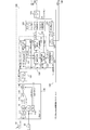
図2は、本技術の実施の形態における衛星追尾部132の構成例を示す図である。
図2は、本技術の実施の形態における衛星追尾部132の構成例を示す図である。
衛星追尾部132は、主に、衛星固有コードとの相関処理、コードタイミング同期、搬送波同期、航法データに対するビット同期、プリアンブル同期を行い、衛星時刻をベースバンド信号のサンプリング周期の精度で再生する。
疑似距離計算部660では、衛星時刻カウンタ650の衛星時刻と受信機基準時刻カウンタ125の受信機基準時刻の1秒以下の桁のカウンタ差分を取ることにより、衛星信号の伝搬時間が推定される。そして、この推定された衛星信号の伝搬時間に光速を乗じることにより、衛星・受信機間の伝搬距離が推定される。ここで推定される伝搬距離は、実際の幾何学距離と比べて、受信機のTCXO周波数オフセットや回路遅延による誤差、電離層や対流圏、マルチパス等による誤差を含んでいるため、疑似距離と呼ばれる。これらの誤差要因は上述の測位計算によって、極力排除され、受信機位置が算出される。
一方、衛星時刻との同期がとれた復調信号は後段の航法データ復号器134に入力され、航法データが復号される。
コードタイミング同期は、拡散符号変調のタイミング(位相)に同期させるための処理である。このコードタイミング同期は、タイミング誤差検出器621、コード同期ループフィルタ622、コード同期NCO(Numerically Controlled Oscillator)623、コード生成器624、および、相関器613により実現される。ここでは、衛星捕捉結果のコード位相を初期値として、コードのタイミング誤差がゼロに収束するようなフィードバックループが形成され、コードタイミングの同期が行われる。
また、搬送波同期は、搬送波(キャリア)に同期させるための処理である。この搬送波同期は、搬送波誤差検出器(搬送波周波数および位相の誤差検出器)631、搬送波同期ループフィルタ632、搬送波同期NCO633、および、ベースバンド信号との乗算器612により実現される。ここでは、衛星捕捉結果の搬送波周波数オフセットを初期値として、搬送波誤差がゼロに収束するようなフィードバックループが形成され、搬送波の同期が行われる。この搬送波同期により、搬送波の周波数オフセットおよび位相が求められ、上述の疑似距離を併せたものが衛星観測値として出力される。
ビット同期は、ビット同期部641により行われる。また、プリアンブル同期は、プリアンブル同期部642により行われる。
[効果]
このように、本技術の第1の実施の形態によれば、1周波のみに対応したGNSS受信回路100および200を連接させることにより、2周波測位を実現することが可能となる。これにより、衛星測位信号受信装置の柔軟な設計が可能となる。例えば、単周波測位のみで十分なアプリケーションに対しては、1つの1周波対応受信回路のみで受信装置を構成することができる。また、2周波測位による高精度が求められるアプリケーションに対しては、2つの1周波対応受信回路より受信装置を構成することができる。これにより、アプリケーション毎に回路コストや消費電力をよりスケーラブルに最適化することが可能となる。
このように、本技術の第1の実施の形態によれば、1周波のみに対応したGNSS受信回路100および200を連接させることにより、2周波測位を実現することが可能となる。これにより、衛星測位信号受信装置の柔軟な設計が可能となる。例えば、単周波測位のみで十分なアプリケーションに対しては、1つの1周波対応受信回路のみで受信装置を構成することができる。また、2周波測位による高精度が求められるアプリケーションに対しては、2つの1周波対応受信回路より受信装置を構成することができる。これにより、アプリケーション毎に回路コストや消費電力をよりスケーラブルに最適化することが可能となる。
<2.第2の実施の形態>
図3は、本技術の第2の実施の形態における衛星測位信号受信装置の構成例を示す図である。
図3は、本技術の第2の実施の形態における衛星測位信号受信装置の構成例を示す図である。
この第2の実施の形態では、上述の第1の実施の形態と比べて、スレーブのGNSS受信回路200がL1のみの1周波対応になっている点のみが異なる。すなわち、衛星捕捉部231および衛星追尾部232がL1のみの1周波対応になっており、GNSS受信回路200からGNSS受信回路100にはL1の航法データおよび衛星観測値が転送される。
このように、本技術の第2の実施の形態によれば、GNSS受信回路200をL1のみの1周波対応とすることにより、上述の第1の実施の形態よりも更に衛星測位信号受信装置全体の回路コストや消費電力を抑えることが可能となる。このとき、上述の第1の実施の形態と比べて、GNSS受信回路の種類が増えるものの、現在最も普及しているL1のみの単周波測位で十分なアプリケーションに対する選択肢を増やすことができる。そのため、アプリケーション毎の回路コストや、消費電力のスケーラビリティを更に改善することができる。
<3.第3の実施の形態>
図4は、本技術の第3の実施の形態における衛星測位信号受信装置の構成例を示す図である。
図4は、本技術の第3の実施の形態における衛星測位信号受信装置の構成例を示す図である。
この第3の実施の形態では、上述の第1の実施の形態と比べて、PPSカウンタ124または224を介さずに、直接、受信機基準時刻カウンタ125および225を同期できるようになっている点のみが異なる。
PPSカウンタ124または224の外部リセットや、PPSカウンタ124または224から受信機基準時刻カウンタ125または225へのリセットは削除されている。それらに代えて、受信機基準時刻カウンタ125および225に対する外部リセット入力、および、リセット出力が追加されている。すなわち、受信機基準時刻カウンタ125および225には、所定カウントのタイミングでリセット信号を1度だけ出力する機能と、外部リセットの入力をトリガとして自身のカウンタをリセットする機能とが追加される。
受信機基準時刻カウンタ125から出力されるリセット信号を、受信機基準時刻カウンタ225の外部リセットに入力する。また、受信機基準時刻カウンタ125はリセット信号を自身の外部リセット信号にループバックする。これにより、受信機基準時刻カウンタ125および225が同時にリセットさせることになり、両者の受信機基準時刻を同期させることができる。
この第3の実施の形態は、GNSS受信回路100および200の双方の受信機時刻を同期させる方法の別形態であり、その他、実現される機能や効果は、上述の第1の実施の形態と同様である。
<4.第4の実施の形態>
図5は、本技術の第4の実施の形態における衛星測位信号受信装置の構成例を示す図である。
図5は、本技術の第4の実施の形態における衛星測位信号受信装置の構成例を示す図である。
この第4の実施の形態では、上述の第1の実施の形態と比べて、GNSS受信回路100の1PPSをトリガとするマスター・スレーブ間のPPSカウンタの同期機構が無くなっている点が異なる。それに代えて、GNSS受信回路200においてもL2/L5の測位計算を行って、GNSS受信回路200自身のPPSカウンタ224の補正を行う。これにより、GNSS受信回路100および200が、それぞれのPPSカウンタ124または224に基づいて、受信機基準時刻を同期させる。
この場合、GNSS受信回路100および200の双方の測位計算が完了し、1PPSの時刻精度が十分に安定するまで、受信機基準時刻の同期や2周波測位を待たせる必要がある。その一方で、PPSカウンタ124および224の外部リセット端子や、GNSS受信回路100および200の間の1PPSの配線を無くすことができる。すなわち、レイアウトの観点で、余計なインターフェースを設ける必要がないという利点がある。
<5.第5の実施の形態>
図6は、本技術の第5の実施の形態における衛星測位信号受信装置の構成例を示す図である。
図6は、本技術の第5の実施の形態における衛星測位信号受信装置の構成例を示す図である。
この第5の実施の形態では、上述の第4の実施の形態と比べて、GNSS受信回路200からGNSS受信回路100へのデータ伝送を、有線ではなく無線により行う点が異なる。このため、この第5の実施の形態では、シリアルインターフェース128または228の先に、無線インターフェース126または226、および、無線伝送用のアンテナ31または32が追加されている。
この第5の実施の形態では、無線を用いることにより、更にマスター・スレーブ間の配線を減らすことができ、GNSS受信回路100および200のレイアウトに対する柔軟性を高めることができる。
<6.第6の実施の形態>
図7は、本技術の第6の実施の形態における衛星測位信号受信装置の構成例を示す図である。
図7は、本技術の第6の実施の形態における衛星測位信号受信装置の構成例を示す図である。
この第6の実施の形態では、上述の第1の実施の形態と比べて、以下の点が異なる。まず、衛星処理ユニット130において衛星捕捉部131がL1のみの対応となっている。また、衛星処理ユニット230において周波数・遅延補正部235が追加されている。また、衛星処理ユニット130において衛星観測値取得部133が衛星観測値を取得した受信機基準時刻(ラッチ時刻)も保持するようになっている。また、シリアルインターフェース128および228を介して、GNSS受信回路100で取得したL1の衛星観測値とラッチ時刻が、GNSS受信回路200に転送されている。
L2やL5の伝送フレームがL1の伝送フレームに同期していることを利用して、L1の衛星追尾結果を用いて、L2やL5の衛星捕捉を行う方式が知られている。このような方式を用いれば、L1と比べてコード系列長が10倍となるL2やコード系列長およびコード帯域が10倍となるL5に対する単独での衛星捕捉に対応する必要がなくなるため、L2/L5による衛星捕捉の回路規模増や消費電力増を避けることができる。この第6の実施の形態は、そのようなL1アシストを用いたL2/L5衛星捕捉を可能とする例である。
GNSS受信回路100で取得したL1の衛星観測値とラッチ時刻は、GNSS受信回路200の周波数・遅延補正部235に入力され、L1とL2/L5の搬送波周波数の違いやラッチ時刻からの経過時間を考慮した衛星観測値の補正が行われる。補正後の衛星観測値よりL2/L5の衛星捕捉情報(搬送波周波数オフセットおよびコード位相)が予測できるため、この予測値を用いて、L2/L5の衛星追尾が可能となる。
具体的には、以下のような手順で衛星観測値を補正し、L2/L5衛星捕捉情報を予測する。まず、ラッチ時刻からの経過時間が十分小さく、経過時間内のドップラー周波数変化が無視できる場合には、L1の搬送波周波数をfL1、L2/L5の搬送波周波数をfLx、衛星観測値に含まれるL1の搬送波周波数オフセットをΔfL1として、L2/L5搬送波周波数オフセットの予測値ΔfLxは、次式のように算出される。
ΔfLx=ΔfL1×fLx/fL1
ΔfLx=ΔfL1×fLx/fL1
一方、経過時間内のドップラー周波数変化が無視できない場合には、連続する複数サンプルの衛星観測値より搬送波周波数オフセットの変化率RfL1を求める。そして、ラッチ時刻から衛星追尾を開始する受信機基準時刻までの経過時間をΔtとすると、ΔfLxは、次式により算出される。
ΔfLx=(ΔfL1+ RfL1・Δt)×fLx/fL1
ΔfLx=(ΔfL1+ RfL1・Δt)×fLx/fL1
また、衛星観測値に含まれる疑似距離からラッチ時の衛星時刻を復元することにより、L1のビット境界やサブフレーム境界が求められる。そして、これに同期しているL2/L5の伝送フレームの位相を経過時間分、進めることにより、L2/L5のコード位相の予測値を求めることができる。
このように、本技術の第6の実施の形態によれば、L1の衛星観測値を用いてL2/L5の衛星追尾を行うことができるため、L2/L5の単独捕捉に対応することによる衛星捕捉の回路規模増を避けることができ、更に回路コストを低減することが可能となる。
<7.第7の実施の形態>
図8は、本技術の第7の実施の形態における衛星測位信号受信装置の構成例を示す図である。
図8は、本技術の第7の実施の形態における衛星測位信号受信装置の構成例を示す図である。
この第7の実施の形態では、上述の第1の実施の形態と比べて、GNSS受信回路100のアンテナ11とGNSS受信回路200のアンテナ12とを別々に設けた点が異なる。
アンテナ11および12を搬送波の1波長以上離して配置すれば、空間的な相関がなくなり、ダイバーシティ効果を得ることができる。すなわち、GNSS受信回路100および200において異なるアンテナ11および12からL1/L2/L5のいずれか同じ周波数バンドの衛星信号を捕捉および追尾し、両者のうちでより復調品質の優れた衛星観測値を選択して、測位計算に用いる。これにより、より安定した単周波測位性能を実現することができる。
また、2つのアンテナ11および12を一定距離だけ離して配置して基線ベクトルを構成することにより、L1/L2/L5のいずれかの単周波を用いたGNSSコンパスとして応用することも可能である。GNSSコンパスとは、RTKの原理を応用した搬送波測位技術であり、これにより基線ベクトルの方位を高精度に求めることができる。
<8.第8の実施の形態>
図9は、本技術の第8の実施の形態における衛星測位信号受信装置の構成例を示す図である。
図9は、本技術の第8の実施の形態における衛星測位信号受信装置の構成例を示す図である。
この第8の実施の形態では、上述の第1の実施の形態と比べて、3周波に対応するため、第2のスレーブとして1周波対応GNSS受信回路300がもう一つ追加されている点が異なる。そして、GNSS受信回路300からのデータも受け取れるよう、GNSS受信回路100にシリアルインターフェース127がもう1つ追加されている点が異なる。
3周波の割り当て例として、GNSS受信回路100(マスター)にL1、GNSS受信回路200(第1のスレーブ)にL2、GNSS受信回路300(第2のスレーブ)にL5を割り当てたときの例を示している。
GNSS受信回路100は、GNSS受信回路300に対しても1PPSを外部リセットとして接続することにより、GNSS受信回路300とも同期をとることができる。また、GNSS受信回路100は、自身で取得したL1の航法データおよび衛星観測値と、GNSS受信回路200より伝送されるL2の航法データおよび衛星観測値と、GNSS受信回路300より伝送されるL5の航法データおよび衛星観測値とを利用する。これにより、測位計算部122では、L1/L2/L5の3周波を用いた測位計算も行えるようになる。
3周波に対応することにより、2周波よりも更に周波数ダイバーシティの効果を高めることができ、妨害に対する耐性向上やより安定した測位性能を実現することができる。また、RTK/PPPに適用する場合には、2周波と比べて更に初期化時間を早めることが可能となる。
<9.第9の実施の形態>
図10は、本技術の第9の実施の形態における衛星測位信号受信装置の構成例を示す図である。
図10は、本技術の第9の実施の形態における衛星測位信号受信装置の構成例を示す図である。
この第9の実施の形態では、上述の第1の実施の形態と比べて、GNSS受信回路がマスターのみ(GNSS受信回路100のみ)となり、マスター・スレーブ間のインターフェースが削除されている。そして、マスター・スレーブ間の同期が不要なことから、PPSカウンタ124から受信機基準時刻カウンタ125へのリセット信号が設けられていない。また、RF回路110において、ADCクロックおよびDSPクロックを生成するためのPLL118が、L1/L2/L5帯の局部発振信号を生成するためのPLL117とは独立に設けられている。
このような構成において、第9の実施の形態の衛星測位信号受信装置では、L1衛星とL2/L5衛星の捕捉および追尾をシーケンシャルに切り替えて行う。
RF回路110では、PLL117および118を、それぞれ局部発振信号の生成とクロック生成とに対応して独立に設けることにより、局部発振周波数の切り替えに依らず、デジタルクロックに対する同期の連続性を維持することができる。なお、PLL117は、特許請求の範囲に記載の第1の位相同期回路の一例である。また、PLL118は、特許請求の範囲に記載の第2の位相同期回路の一例である。
デジタル信号処理部120では、まず、L1の衛星を捕捉および追尾した後に、その衛星観測値およびラッチ時刻を用いて、L2/L5の捕捉予測値を生成する。次に、RF回路110の局部発振周波数をL2/L5に切り替えてから、先に生成した予測値を用いて、L2/L5の衛星追尾を開始する。
このように、本技術の第9の実施の形態によれば、2周波同時観測や2周波測位には対応できないが、L2/L5用の衛星捕捉回路や衛星処理ユニットを追加することなく、最小限の回路コストで、L1/L2/L5いずれかの単周波測位に対応することができる。すなわち、妨害耐性の向上や、近代化GNSS信号による位置精度、マルチパス耐性および感度の向上が得られる。
[まとめ]
以上、説明した通り、本技術の実施の形態では、1周波のみに対応したGNSS受信回路を1個または複数個備え、それぞれの受信回路を同期するための同期制御インターフェースと各受信回路間で衛星観測情報を共有するための伝送インターフェースを備える。これにより、1周波または2周波以上の多周波測位を実現することができ、求められる周波数バンド数に応じてGNSS受信回路を段階的に増設することにより、アプリケーション毎に回路コストや消費電力を最適化することが可能となる。
以上、説明した通り、本技術の実施の形態では、1周波のみに対応したGNSS受信回路を1個または複数個備え、それぞれの受信回路を同期するための同期制御インターフェースと各受信回路間で衛星観測情報を共有するための伝送インターフェースを備える。これにより、1周波または2周波以上の多周波測位を実現することができ、求められる周波数バンド数に応じてGNSS受信回路を段階的に増設することにより、アプリケーション毎に回路コストや消費電力を最適化することが可能となる。
なお、上述の実施の形態は本技術を具現化するための一例を示したものであり、実施の形態における事項と、特許請求の範囲における発明特定事項とはそれぞれ対応関係を有する。同様に、特許請求の範囲における発明特定事項と、これと同一名称を付した本技術の実施の形態における事項とはそれぞれ対応関係を有する。ただし、本技術は実施の形態に限定されるものではなく、その要旨を逸脱しない範囲において実施の形態に種々の変形を施すことにより具現化することができる。
なお、本明細書に記載された効果はあくまで例示であって、限定されるものではなく、また、他の効果があってもよい。
なお、本技術は以下のような構成もとることができる。
(1)単一の周波数帯に対応して衛星測位信号を受信して衛星観測情報を生成する衛星測位信号受信回路を少なくとも1つ具備する衛星測位信号受信装置であって、
前記衛星測位信号受信回路の各々は、前記衛星測位信号受信回路の間で同期させるための同期制御インターフェースと、前記衛星測位信号受信回路の間で前記衛星観測情報を共有するための衛星情報伝送インターフェースとを備え、
前記衛星観測情報に基づいて測位を行う衛星測位信号受信装置。
(2)前記同期制御インターフェースは、1秒周期の矩形パルス信号の出力信号と、前記矩形パルス信号を生成するパルスカウンタをリセットする外部リセット入力信号を備え、
前記衛星測位信号受信回路の各々は、前記外部リセット入力信号に基づいて前記パルスカウンタをリセットし、前記衛星測位信号受信回路の基準時刻を計数する基準時刻カウンタを前記パルスカウンタのカウント時刻に基づいてリセットする
前記(1)に記載の衛星測位信号受信装置。
(3)前記同期制御インターフェースは、前記衛星測位信号受信回路の基準時刻を計数する基準時刻カウンタのリセット出力信号と、前記基準時刻カウンタに対する外部リセット入力信号を備え、
前記衛星測位信号受信回路の各々は、前記外部リセット入力信号に基づいて前記基準時刻カウンタをリセットし、前記基準時刻カウンタのカウント時刻に基づいて前記リセット出力信号を出力する
前記(1)に記載の衛星測位信号受信装置。
(4)前記衛星測位信号受信回路の各々は、前記同期制御インターフェースに代えて、1秒周期の矩形パルス信号を生成するパルスカウンタのカウント時刻に基づいて、前記衛星測位信号受信回路の基準時刻を計数する基準時刻カウンタをリセットすることにより、前記矩形パルス信号の時刻精度で同期させる
前記(1)に記載の衛星測位信号受信装置。
(5)前記衛星情報伝送インターフェースは有線インターフェースである
前記(1)から(4)のいずれかに記載の衛星測位信号受信装置。
(6)前記衛星情報伝送インターフェースは有線のシリアルインターフェースである
前記(5)に記載の衛星測位信号受信装置。
(7)前記衛星情報伝送インターフェースは無線インターフェースである
前記(1)から(4)のいずれかに記載の衛星測位信号受信装置。
(8)前記衛星測位信号受信回路のうち第1の周波数帯以外を受信する衛星測位信号受信回路は、前記第1の周波数帯を受信する衛星測位信号受信回路から得られる衛星観測情報を用いて衛星捕捉を行う
前記(1)に記載の衛星測位信号受信装置。
(9)前記衛星測位信号受信回路の各々は、それぞれ独立にアンテナを備える
前記(1)に記載の衛星測位信号受信装置。
(10)第1および第2の衛星測位信号受信回路を具備する衛星測位信号受信装置であって、
前記第1および第2の衛星測位信号受信回路の各々は、単一の周波数帯に対応して高周波信号をデジタル信号に変換する高周波処理部と、基準時刻を計数する基準時刻カウンタと、前記基準時刻に従って前記デジタル信号に基づいて衛星捕捉および衛星追尾を行うデジタル信号処理部とを備え、
前記第1および第2の衛星測位信号受信回路の前記基準時刻カウンタは、互いに同期して前記基準時刻を計数し、
前記第2の衛星測位信号受信回路は、前記第1の衛星測位信号受信回路とは異なる第2の周波数帯の衛星観測情報を取得して前記第1の衛星測位信号受信回路に供給し、
前記第1の衛星測位信号受信回路は、前記第2の衛星測位信号受信回路とは異なる第1の周波数帯の衛星観測情報を取得して、前記第2の衛星測位信号受信回路から供給された前記第2の周波数帯の衛星観測情報と併せて複数の周波数帯の衛星観測情報を用いた測位を行う
衛星測位信号受信装置。
(11)前記第2の衛星測位信号受信回路のデジタル信号処理部は、前記第2の周波数帯のみに対応した回路構成である
前記(10)に記載の衛星測位信号受信装置。
(12)前記第1および第2の衛星測位信号受信回路の各々は、1秒周期の矩形パルス信号を外部に出力するパルスカウンタをさらに備え、
前記第2の衛星測位信号受信回路の前記パルスカウンタは、前記第1の衛星測位信号受信回路の前記パルスカウンタによりリセットされ、
前記第1および第2の衛星測位信号受信回路の各々において前記パルスカウンタに従って前記基準時刻カウンタをリセットすることにより、前記第1および第2の衛星測位信号受信回路の前記基準時刻カウンタを互いに同期させる
前記(10)に記載の衛星測位信号受信装置。
(13)前記第1の衛星測位信号受信回路の前記基準時刻カウンタは、前記基準時刻をリセットする基準時刻リセット信号を出力し、
前記第1および第2の衛星測位信号受信回路の前記基準時刻カウンタが前記基準時刻リセット信号に従って前記基準時刻カウンタをリセットすることにより、前記第1および第2の衛星測位信号受信回路の前記基準時刻カウンタを互いに同期させる
前記(10)に記載の衛星測位信号受信装置。
(14)前記第1および第2の衛星測位信号受信回路の各々は、1秒周期の矩形パルス信号を外部に出力するパルスカウンタをさらに備え、
前記第2の衛星測位信号受信回路のデジタル信号処理部は、前記第2の周波数帯の衛星観測情報を用いて測位を行い、
前記第2の衛星測位信号受信回路の前記パルスカウンタは、前記第2の周波数帯の衛星観測情報を用いた測位結果に基づいて補正され、
前記第1および第2の衛星測位信号受信回路の各々において前記パルスカウンタに従って前記基準時刻カウンタをリセットすることにより、前記第1および第2の衛星測位信号受信回路の前記基準時刻カウンタを互いに同期させる
前記(10)に記載の衛星測位信号受信装置。
(15)前記第1および第2の衛星測位信号受信回路の各々は、前記第2の衛星測位信号受信回路から前記第1の衛星測位信号受信回路に前記第2の周波数帯の衛星観測情報を供給する無線インターフェースを備える
前記(10)から(14)のいずれかに記載の衛星測位信号受信装置。
(16)前記第1の衛星測位信号受信回路は、前記第1の周波数帯の衛星観測情報を前記第2の衛星測位信号受信回路に供給し、
前記第2の衛星測位信号受信回路は、前記第1の衛星測位信号受信回路から供給された前記第1の周波数帯の衛星観測情報を補正する衛星観測値補正部を備え、この補正結果に基づいて前記第2の周波数帯の衛星追尾を行う
前記(10)に記載の衛星測位信号受信装置。
(17)前記第1および第2の衛星測位信号受信回路の各々は、前記高周波処理部に高周波信号を供給するアンテナをそれぞれ備える
前記(10)に記載の衛星測位信号受信装置。
(18)前記高周波処理部と、前記基準時刻カウンタと、前記デジタル信号処理部とを備える第3の衛星測位信号受信回路をさらに具備し、
前記第1および第3の衛星測位信号受信回路の前記基準時刻カウンタは、互いに同期して前記基準時刻を計数し、
前記第3の衛星測位信号受信回路は、前記第1の衛星測位信号受信回路とは異なる第3の周波数帯の衛星観測情報を取得して前記第1の衛星測位信号受信回路に供給し、
前記第1の衛星測位信号受信回路は、前記第3の衛星測位信号受信回路から供給された前記第3の周波数帯の衛星観測情報と併せて複数の周波数帯の衛星観測情報を用いた測位を行う
前記(10)に記載の衛星測位信号受信装置。
(19)単一の周波数帯に対応して高周波信号をデジタル信号に変換する高周波処理部と、
基準時刻に従って前記デジタル信号に基づいて衛星捕捉および衛星追尾を行うデジタル信号処理部と、
前記高周波処理部に対して順次異なる周波数帯の局部発振器信号を供給する第1の位相同期回路と、
前記第1の位相同期回路とは独立して前記高周波処理部のアナログ/デジタル変換器および前記デジタル信号処理部に対してクロック信号を供給する第2の位相同期回路と
を具備する衛星測位信号受信装置。
(1)単一の周波数帯に対応して衛星測位信号を受信して衛星観測情報を生成する衛星測位信号受信回路を少なくとも1つ具備する衛星測位信号受信装置であって、
前記衛星測位信号受信回路の各々は、前記衛星測位信号受信回路の間で同期させるための同期制御インターフェースと、前記衛星測位信号受信回路の間で前記衛星観測情報を共有するための衛星情報伝送インターフェースとを備え、
前記衛星観測情報に基づいて測位を行う衛星測位信号受信装置。
(2)前記同期制御インターフェースは、1秒周期の矩形パルス信号の出力信号と、前記矩形パルス信号を生成するパルスカウンタをリセットする外部リセット入力信号を備え、
前記衛星測位信号受信回路の各々は、前記外部リセット入力信号に基づいて前記パルスカウンタをリセットし、前記衛星測位信号受信回路の基準時刻を計数する基準時刻カウンタを前記パルスカウンタのカウント時刻に基づいてリセットする
前記(1)に記載の衛星測位信号受信装置。
(3)前記同期制御インターフェースは、前記衛星測位信号受信回路の基準時刻を計数する基準時刻カウンタのリセット出力信号と、前記基準時刻カウンタに対する外部リセット入力信号を備え、
前記衛星測位信号受信回路の各々は、前記外部リセット入力信号に基づいて前記基準時刻カウンタをリセットし、前記基準時刻カウンタのカウント時刻に基づいて前記リセット出力信号を出力する
前記(1)に記載の衛星測位信号受信装置。
(4)前記衛星測位信号受信回路の各々は、前記同期制御インターフェースに代えて、1秒周期の矩形パルス信号を生成するパルスカウンタのカウント時刻に基づいて、前記衛星測位信号受信回路の基準時刻を計数する基準時刻カウンタをリセットすることにより、前記矩形パルス信号の時刻精度で同期させる
前記(1)に記載の衛星測位信号受信装置。
(5)前記衛星情報伝送インターフェースは有線インターフェースである
前記(1)から(4)のいずれかに記載の衛星測位信号受信装置。
(6)前記衛星情報伝送インターフェースは有線のシリアルインターフェースである
前記(5)に記載の衛星測位信号受信装置。
(7)前記衛星情報伝送インターフェースは無線インターフェースである
前記(1)から(4)のいずれかに記載の衛星測位信号受信装置。
(8)前記衛星測位信号受信回路のうち第1の周波数帯以外を受信する衛星測位信号受信回路は、前記第1の周波数帯を受信する衛星測位信号受信回路から得られる衛星観測情報を用いて衛星捕捉を行う
前記(1)に記載の衛星測位信号受信装置。
(9)前記衛星測位信号受信回路の各々は、それぞれ独立にアンテナを備える
前記(1)に記載の衛星測位信号受信装置。
(10)第1および第2の衛星測位信号受信回路を具備する衛星測位信号受信装置であって、
前記第1および第2の衛星測位信号受信回路の各々は、単一の周波数帯に対応して高周波信号をデジタル信号に変換する高周波処理部と、基準時刻を計数する基準時刻カウンタと、前記基準時刻に従って前記デジタル信号に基づいて衛星捕捉および衛星追尾を行うデジタル信号処理部とを備え、
前記第1および第2の衛星測位信号受信回路の前記基準時刻カウンタは、互いに同期して前記基準時刻を計数し、
前記第2の衛星測位信号受信回路は、前記第1の衛星測位信号受信回路とは異なる第2の周波数帯の衛星観測情報を取得して前記第1の衛星測位信号受信回路に供給し、
前記第1の衛星測位信号受信回路は、前記第2の衛星測位信号受信回路とは異なる第1の周波数帯の衛星観測情報を取得して、前記第2の衛星測位信号受信回路から供給された前記第2の周波数帯の衛星観測情報と併せて複数の周波数帯の衛星観測情報を用いた測位を行う
衛星測位信号受信装置。
(11)前記第2の衛星測位信号受信回路のデジタル信号処理部は、前記第2の周波数帯のみに対応した回路構成である
前記(10)に記載の衛星測位信号受信装置。
(12)前記第1および第2の衛星測位信号受信回路の各々は、1秒周期の矩形パルス信号を外部に出力するパルスカウンタをさらに備え、
前記第2の衛星測位信号受信回路の前記パルスカウンタは、前記第1の衛星測位信号受信回路の前記パルスカウンタによりリセットされ、
前記第1および第2の衛星測位信号受信回路の各々において前記パルスカウンタに従って前記基準時刻カウンタをリセットすることにより、前記第1および第2の衛星測位信号受信回路の前記基準時刻カウンタを互いに同期させる
前記(10)に記載の衛星測位信号受信装置。
(13)前記第1の衛星測位信号受信回路の前記基準時刻カウンタは、前記基準時刻をリセットする基準時刻リセット信号を出力し、
前記第1および第2の衛星測位信号受信回路の前記基準時刻カウンタが前記基準時刻リセット信号に従って前記基準時刻カウンタをリセットすることにより、前記第1および第2の衛星測位信号受信回路の前記基準時刻カウンタを互いに同期させる
前記(10)に記載の衛星測位信号受信装置。
(14)前記第1および第2の衛星測位信号受信回路の各々は、1秒周期の矩形パルス信号を外部に出力するパルスカウンタをさらに備え、
前記第2の衛星測位信号受信回路のデジタル信号処理部は、前記第2の周波数帯の衛星観測情報を用いて測位を行い、
前記第2の衛星測位信号受信回路の前記パルスカウンタは、前記第2の周波数帯の衛星観測情報を用いた測位結果に基づいて補正され、
前記第1および第2の衛星測位信号受信回路の各々において前記パルスカウンタに従って前記基準時刻カウンタをリセットすることにより、前記第1および第2の衛星測位信号受信回路の前記基準時刻カウンタを互いに同期させる
前記(10)に記載の衛星測位信号受信装置。
(15)前記第1および第2の衛星測位信号受信回路の各々は、前記第2の衛星測位信号受信回路から前記第1の衛星測位信号受信回路に前記第2の周波数帯の衛星観測情報を供給する無線インターフェースを備える
前記(10)から(14)のいずれかに記載の衛星測位信号受信装置。
(16)前記第1の衛星測位信号受信回路は、前記第1の周波数帯の衛星観測情報を前記第2の衛星測位信号受信回路に供給し、
前記第2の衛星測位信号受信回路は、前記第1の衛星測位信号受信回路から供給された前記第1の周波数帯の衛星観測情報を補正する衛星観測値補正部を備え、この補正結果に基づいて前記第2の周波数帯の衛星追尾を行う
前記(10)に記載の衛星測位信号受信装置。
(17)前記第1および第2の衛星測位信号受信回路の各々は、前記高周波処理部に高周波信号を供給するアンテナをそれぞれ備える
前記(10)に記載の衛星測位信号受信装置。
(18)前記高周波処理部と、前記基準時刻カウンタと、前記デジタル信号処理部とを備える第3の衛星測位信号受信回路をさらに具備し、
前記第1および第3の衛星測位信号受信回路の前記基準時刻カウンタは、互いに同期して前記基準時刻を計数し、
前記第3の衛星測位信号受信回路は、前記第1の衛星測位信号受信回路とは異なる第3の周波数帯の衛星観測情報を取得して前記第1の衛星測位信号受信回路に供給し、
前記第1の衛星測位信号受信回路は、前記第3の衛星測位信号受信回路から供給された前記第3の周波数帯の衛星観測情報と併せて複数の周波数帯の衛星観測情報を用いた測位を行う
前記(10)に記載の衛星測位信号受信装置。
(19)単一の周波数帯に対応して高周波信号をデジタル信号に変換する高周波処理部と、
基準時刻に従って前記デジタル信号に基づいて衛星捕捉および衛星追尾を行うデジタル信号処理部と、
前記高周波処理部に対して順次異なる周波数帯の局部発振器信号を供給する第1の位相同期回路と、
前記第1の位相同期回路とは独立して前記高周波処理部のアナログ/デジタル変換器および前記デジタル信号処理部に対してクロック信号を供給する第2の位相同期回路と
を具備する衛星測位信号受信装置。
10~12、31、32 アンテナ
100、200、300 GNSS受信回路
108、208、308 1PPS出力
110、210、310 RF回路(高周波回路)
111、211、311 LNA(Low Noise Amplifier)
112、117、118、212、312 PLL(Phase Locked Loop)
113、213、313 MIX(ミキサー回路)
114、214、314 LPF(Low Pass Filter)
115、215、315 AGC(Auto Gain Control)
116、216、316 ADC(Analog-to-Digital Converter)
120、220、320 デジタル信号処理部
121、221、321 デジタルフロントエンド
122、222、322 測位計算部
123、223、323 PPS補正部
124、224、324 PPSカウンタ
125、225、325 受信機基準時刻カウンタ
126、226 無線インターフェース
127~129、227~229、327 シリアルインターフェース
130、230、330 衛星処理ユニット
131、231 衛星捕捉部
132、232 衛星追尾部
133、233 衛星観測値取得部
134、234 航法データ復号器
135、235 周波数・遅延補正部
612 乗算器
613 相関器
621 タイミング誤差検出器
622 コード同期ループフィルタ
623 コード同期NCO
624 コード生成器
632 搬送波同期ループフィルタ
633 搬送波同期NCO
641 ビット同期部
642 プリアンブル同期部
650 衛星時刻カウンタ
660 疑似距離計算部
100、200、300 GNSS受信回路
108、208、308 1PPS出力
110、210、310 RF回路(高周波回路)
111、211、311 LNA(Low Noise Amplifier)
112、117、118、212、312 PLL(Phase Locked Loop)
113、213、313 MIX(ミキサー回路)
114、214、314 LPF(Low Pass Filter)
115、215、315 AGC(Auto Gain Control)
116、216、316 ADC(Analog-to-Digital Converter)
120、220、320 デジタル信号処理部
121、221、321 デジタルフロントエンド
122、222、322 測位計算部
123、223、323 PPS補正部
124、224、324 PPSカウンタ
125、225、325 受信機基準時刻カウンタ
126、226 無線インターフェース
127~129、227~229、327 シリアルインターフェース
130、230、330 衛星処理ユニット
131、231 衛星捕捉部
132、232 衛星追尾部
133、233 衛星観測値取得部
134、234 航法データ復号器
135、235 周波数・遅延補正部
612 乗算器
613 相関器
621 タイミング誤差検出器
622 コード同期ループフィルタ
623 コード同期NCO
624 コード生成器
632 搬送波同期ループフィルタ
633 搬送波同期NCO
641 ビット同期部
642 プリアンブル同期部
650 衛星時刻カウンタ
660 疑似距離計算部
Claims (19)
- 単一の周波数帯に対応して衛星測位信号を受信して衛星観測情報を生成する衛星測位信号受信回路を少なくとも1つ具備する衛星測位信号受信装置であって、
前記衛星測位信号受信回路の各々は、前記衛星測位信号受信回路の間で同期させるための同期制御インターフェースと、前記衛星測位信号受信回路の間で前記衛星観測情報を共有するための衛星情報伝送インターフェースとを備え、
前記衛星観測情報に基づいて測位を行う衛星測位信号受信装置。 - 前記同期制御インターフェースは、1秒周期の矩形パルス信号の出力信号と、前記矩形パルス信号を生成するパルスカウンタをリセットする外部リセット入力信号を備え、
前記衛星測位信号受信回路の各々は、前記外部リセット入力信号に基づいて前記パルスカウンタをリセットし、前記衛星測位信号受信回路の基準時刻を計数する基準時刻カウンタを前記パルスカウンタのカウント時刻に基づいてリセットする
請求項1記載の衛星測位信号受信装置。 - 前記同期制御インターフェースは、前記衛星測位信号受信回路の基準時刻を計数する基準時刻カウンタのリセット出力信号と、前記基準時刻カウンタに対する外部リセット入力信号を備え、
前記衛星測位信号受信回路の各々は、前記外部リセット入力信号に基づいて前記基準時刻カウンタをリセットし、前記基準時刻カウンタのカウント時刻に基づいて前記リセット出力信号を出力する
請求項1記載の衛星測位信号受信装置。 - 前記衛星測位信号受信回路の各々は、前記同期制御インターフェースに代えて、1秒周期の矩形パルス信号を生成するパルスカウンタのカウント時刻に基づいて、前記衛星測位信号受信回路の基準時刻を計数する基準時刻カウンタをリセットすることにより、前記矩形パルス信号の時刻精度で同期させる
請求項1記載の衛星測位信号受信装置。 - 前記衛星情報伝送インターフェースは有線インターフェースである
請求項1記載の衛星測位信号受信装置。 - 前記衛星情報伝送インターフェースは有線のシリアルインターフェースである
請求項5記載の衛星測位信号受信装置。 - 前記衛星情報伝送インターフェースは無線インターフェースである
請求項1記載の衛星測位信号受信装置。 - 前記衛星測位信号受信回路のうち第1の周波数帯以外を受信する衛星測位信号受信回路は、前記第1の周波数帯を受信する衛星測位信号受信回路から得られる衛星観測情報を用いて衛星捕捉を行う
請求項1記載の衛星測位信号受信装置。 - 前記衛星測位信号受信回路の各々は、それぞれ独立にアンテナを備える
請求項1記載の衛星測位信号受信装置。 - 第1および第2の衛星測位信号受信回路を具備する衛星測位信号受信装置であって、
前記第1および第2の衛星測位信号受信回路の各々は、単一の周波数帯に対応して高周波信号をデジタル信号に変換する高周波処理部と、基準時刻を計数する基準時刻カウンタと、前記基準時刻に従って前記デジタル信号に基づいて衛星捕捉および衛星追尾を行うデジタル信号処理部とを備え、
前記第1および第2の衛星測位信号受信回路の前記基準時刻カウンタは、互いに同期して前記基準時刻を計数し、
前記第2の衛星測位信号受信回路は、前記第1の衛星測位信号受信回路とは異なる第2の周波数帯の衛星観測情報を取得して前記第1の衛星測位信号受信回路に供給し、
前記第1の衛星測位信号受信回路は、前記第2の衛星測位信号受信回路とは異なる第1の周波数帯の衛星観測情報を取得して、前記第2の衛星測位信号受信回路から供給された前記第2の周波数帯の衛星観測情報と併せて複数の周波数帯の衛星観測情報を用いた測位を行う
衛星測位信号受信装置。 - 前記第2の衛星測位信号受信回路のデジタル信号処理部は、前記第2の周波数帯のみに対応した回路構成である
請求項10記載の衛星測位信号受信装置。 - 前記第1および第2の衛星測位信号受信回路の各々は、1秒周期の矩形パルス信号を外部に出力するパルスカウンタをさらに備え、
前記第2の衛星測位信号受信回路の前記パルスカウンタは、前記第1の衛星測位信号受信回路の前記パルスカウンタによりリセットされ、
前記第1および第2の衛星測位信号受信回路の各々において前記パルスカウンタに従って前記基準時刻カウンタをリセットすることにより、前記第1および第2の衛星測位信号受信回路の前記基準時刻カウンタを互いに同期させる
請求項10記載の衛星測位信号受信装置。 - 前記第1の衛星測位信号受信回路の前記基準時刻カウンタは、前記基準時刻をリセットする基準時刻リセット信号を出力し、
前記第1および第2の衛星測位信号受信回路の前記基準時刻カウンタが前記基準時刻リセット信号に従って前記基準時刻カウンタをリセットすることにより、前記第1および第2の衛星測位信号受信回路の前記基準時刻カウンタを互いに同期させる
請求項10記載の衛星測位信号受信装置。 - 前記第1および第2の衛星測位信号受信回路の各々は、1秒周期の矩形パルス信号を外部に出力するパルスカウンタをさらに備え、
前記第2の衛星測位信号受信回路のデジタル信号処理部は、前記第2の周波数帯の衛星観測情報を用いて測位を行い、
前記第2の衛星測位信号受信回路の前記パルスカウンタは、前記第2の周波数帯の衛星観測情報を用いた測位結果に基づいて補正され、
前記第1および第2の衛星測位信号受信回路の各々において前記パルスカウンタに従って前記基準時刻カウンタをリセットすることにより、前記第1および第2の衛星測位信号受信回路の前記基準時刻カウンタを互いに同期させる
請求項10記載の衛星測位信号受信装置。 - 前記第1および第2の衛星測位信号受信回路の各々は、前記第2の衛星測位信号受信回路から前記第1の衛星測位信号受信回路に前記第2の周波数帯の衛星観測情報を供給する無線インターフェースを備える
請求項10記載の衛星測位信号受信装置。 - 前記第1の衛星測位信号受信回路は、前記第1の周波数帯の衛星観測情報を前記第2の衛星測位信号受信回路に供給し、
前記第2の衛星測位信号受信回路は、前記第1の衛星測位信号受信回路から供給された前記第1の周波数帯の衛星観測情報を補正する衛星観測値補正部を備え、この補正結果に基づいて前記第2の周波数帯の衛星追尾を行う
請求項10記載の衛星測位信号受信装置。 - 前記第1および第2の衛星測位信号受信回路の各々は、前記高周波処理部に高周波信号を供給するアンテナをそれぞれ備える
請求項10記載の衛星測位信号受信装置。 - 前記高周波処理部と、前記基準時刻カウンタと、前記デジタル信号処理部とを備える第3の衛星測位信号受信回路をさらに具備し、
前記第1および第3の衛星測位信号受信回路の前記基準時刻カウンタは、互いに同期して前記基準時刻を計数し、
前記第3の衛星測位信号受信回路は、前記第1の衛星測位信号受信回路とは異なる第3の周波数帯の衛星観測情報を取得して前記第1の衛星測位信号受信回路に供給し、
前記第1の衛星測位信号受信回路は、前記第3の衛星測位信号受信回路から供給された前記第3の周波数帯の衛星観測情報と併せて複数の周波数帯の衛星観測情報を用いた測位を行う
請求項10記載の衛星測位信号受信装置。 - 単一の周波数帯に対応して高周波信号をデジタル信号に変換する高周波処理部と、
基準時刻に従って前記デジタル信号に基づいて衛星捕捉および衛星追尾を行うデジタル信号処理部と、
前記高周波処理部に対して順次異なる周波数帯の局部発振器信号を供給する第1の位相同期回路と、
前記第1の位相同期回路とは独立して前記高周波処理部のアナログ/デジタル変換器および前記デジタル信号処理部に対してクロック信号を供給する第2の位相同期回路と
を具備する衛星測位信号受信装置。
Priority Applications (3)
| Application Number | Priority Date | Filing Date | Title |
|---|---|---|---|
| JP2019570298A JP7161500B2 (ja) | 2018-02-09 | 2018-11-07 | 衛星測位信号受信装置 |
| CN201880087712.8A CN111656223A (zh) | 2018-02-09 | 2018-11-07 | 卫星定位信号接收装置 |
| US16/964,912 US11841445B2 (en) | 2018-02-09 | 2018-11-07 | Satellite positioning signal receiving device |
Applications Claiming Priority (2)
| Application Number | Priority Date | Filing Date | Title |
|---|---|---|---|
| JP2018021855 | 2018-02-09 | ||
| JP2018-021855 | 2018-02-09 |
Publications (1)
| Publication Number | Publication Date |
|---|---|
| WO2019155703A1 true WO2019155703A1 (ja) | 2019-08-15 |
Family
ID=67548395
Family Applications (1)
| Application Number | Title | Priority Date | Filing Date |
|---|---|---|---|
| PCT/JP2018/041272 Ceased WO2019155703A1 (ja) | 2018-02-09 | 2018-11-07 | 衛星測位信号受信装置 |
Country Status (4)
| Country | Link |
|---|---|
| US (1) | US11841445B2 (ja) |
| JP (1) | JP7161500B2 (ja) |
| CN (1) | CN111656223A (ja) |
| WO (1) | WO2019155703A1 (ja) |
Cited By (3)
| Publication number | Priority date | Publication date | Assignee | Title |
|---|---|---|---|---|
| JPWO2021199667A1 (ja) * | 2020-03-30 | 2021-10-07 | ||
| JP2023037995A (ja) * | 2021-09-06 | 2023-03-16 | アンリツ株式会社 | 測定装置、及び測定方法 |
| US11774601B2 (en) * | 2021-02-23 | 2023-10-03 | Viavi Solutions Inc. | Satellite signal propagation delay test device |
Families Citing this family (5)
| Publication number | Priority date | Publication date | Assignee | Title |
|---|---|---|---|---|
| EP3930393B1 (en) * | 2019-02-22 | 2025-12-17 | Ntt Docomo, Inc. | User device and base station device |
| EP3889647A1 (en) * | 2020-03-30 | 2021-10-06 | Polar Electro Oy | Positioning of wearable training computer |
| US11940542B2 (en) * | 2021-02-18 | 2024-03-26 | Mediatek Inc. | Method of using multiple received satellite signals to compensate satellite multipath estimation error |
| CN116094578B (zh) * | 2023-04-07 | 2023-06-09 | 北京航空航天大学 | 一种基于风险事件监测的gbas工作模式自适应切换方法 |
| CN117233814B (zh) * | 2023-09-18 | 2024-11-22 | 昆明理工大学 | 一种基于单频接收设备的实时高精度定位方法及系统 |
Citations (8)
| Publication number | Priority date | Publication date | Assignee | Title |
|---|---|---|---|---|
| JPS6447982A (en) * | 1987-08-18 | 1989-02-22 | Toshiba Corp | Multi-channel gps receiver |
| JPH1054871A (ja) * | 1996-08-09 | 1998-02-24 | Japan Radio Co Ltd | 衛星測位装置 |
| JP2009300274A (ja) * | 2008-06-13 | 2009-12-24 | Casio Comput Co Ltd | Gps受信装置、及びその情報取得方法 |
| JP2012173213A (ja) * | 2011-02-23 | 2012-09-10 | Japan Radio Co Ltd | 測位支援装置 |
| US20130141277A1 (en) * | 2011-12-06 | 2013-06-06 | Daming Hang | Adding Multi-System Functionalities to Legacy Navigation Satellite System Receivers |
| WO2015112368A1 (en) * | 2014-01-24 | 2015-07-30 | Qualcomm Incorporated | Methods and systems for multi-gnss operation |
| JP2015184002A (ja) * | 2014-03-20 | 2015-10-22 | カシオ計算機株式会社 | 電子機器システム、端末機器、及び電子機器システムの制御方法、制御プログラム |
| WO2016027727A1 (ja) * | 2014-08-20 | 2016-02-25 | ソニー株式会社 | 全地球航法衛星システムの受信装置および受信方法、並びにプログラム |
Family Cites Families (8)
| Publication number | Priority date | Publication date | Assignee | Title |
|---|---|---|---|---|
| JP3970153B2 (ja) * | 2002-10-28 | 2007-09-05 | セイコークロック株式会社 | 時刻情報取得方法、時刻情報取得装置及び電波修正時計 |
| US8639416B2 (en) * | 2003-03-20 | 2014-01-28 | Agjunction Llc | GNSS guidance and machine control |
| JP2008051567A (ja) | 2006-08-23 | 2008-03-06 | Japan Radio Co Ltd | 衛星航法装置 |
| US20130176171A1 (en) * | 2008-12-11 | 2013-07-11 | Mark R. Webber | Gnss superband asic and method with simultaneous multi-frequency down conversion |
| US20160245923A1 (en) * | 2008-12-11 | 2016-08-25 | Hemisphere Gnss Inc. | Global navigation satellite system superband processing device and method |
| US8217833B2 (en) * | 2008-12-11 | 2012-07-10 | Hemisphere Gps Llc | GNSS superband ASIC with simultaneous multi-frequency down conversion |
| US8897407B2 (en) * | 2011-12-04 | 2014-11-25 | Hemisphere Gnss Inc. | RF (including GNSS) signal interference mitigation system and method |
| JP2017173046A (ja) * | 2016-03-22 | 2017-09-28 | セイコーエプソン株式会社 | 衛星信号受信装置 |
-
2018
- 2018-11-07 US US16/964,912 patent/US11841445B2/en active Active
- 2018-11-07 WO PCT/JP2018/041272 patent/WO2019155703A1/ja not_active Ceased
- 2018-11-07 JP JP2019570298A patent/JP7161500B2/ja active Active
- 2018-11-07 CN CN201880087712.8A patent/CN111656223A/zh not_active Withdrawn
Patent Citations (8)
| Publication number | Priority date | Publication date | Assignee | Title |
|---|---|---|---|---|
| JPS6447982A (en) * | 1987-08-18 | 1989-02-22 | Toshiba Corp | Multi-channel gps receiver |
| JPH1054871A (ja) * | 1996-08-09 | 1998-02-24 | Japan Radio Co Ltd | 衛星測位装置 |
| JP2009300274A (ja) * | 2008-06-13 | 2009-12-24 | Casio Comput Co Ltd | Gps受信装置、及びその情報取得方法 |
| JP2012173213A (ja) * | 2011-02-23 | 2012-09-10 | Japan Radio Co Ltd | 測位支援装置 |
| US20130141277A1 (en) * | 2011-12-06 | 2013-06-06 | Daming Hang | Adding Multi-System Functionalities to Legacy Navigation Satellite System Receivers |
| WO2015112368A1 (en) * | 2014-01-24 | 2015-07-30 | Qualcomm Incorporated | Methods and systems for multi-gnss operation |
| JP2015184002A (ja) * | 2014-03-20 | 2015-10-22 | カシオ計算機株式会社 | 電子機器システム、端末機器、及び電子機器システムの制御方法、制御プログラム |
| WO2016027727A1 (ja) * | 2014-08-20 | 2016-02-25 | ソニー株式会社 | 全地球航法衛星システムの受信装置および受信方法、並びにプログラム |
Cited By (7)
| Publication number | Priority date | Publication date | Assignee | Title |
|---|---|---|---|---|
| JPWO2021199667A1 (ja) * | 2020-03-30 | 2021-10-07 | ||
| JP7235166B2 (ja) | 2020-03-30 | 2023-03-08 | 日本電気株式会社 | 基地局、通信システム、通信方法、及びプログラム |
| JP2023075168A (ja) * | 2020-03-30 | 2023-05-30 | 日本電気株式会社 | 基地局、通信システム、通信方法、及びプログラム |
| JP7501698B2 (ja) | 2020-03-30 | 2024-06-18 | 日本電気株式会社 | 基地局及び通信方法 |
| US11774601B2 (en) * | 2021-02-23 | 2023-10-03 | Viavi Solutions Inc. | Satellite signal propagation delay test device |
| JP2023037995A (ja) * | 2021-09-06 | 2023-03-16 | アンリツ株式会社 | 測定装置、及び測定方法 |
| JP7376542B2 (ja) | 2021-09-06 | 2023-11-08 | アンリツ株式会社 | 測定装置、及び測定方法 |
Also Published As
| Publication number | Publication date |
|---|---|
| JPWO2019155703A1 (ja) | 2021-01-28 |
| US20210033736A1 (en) | 2021-02-04 |
| CN111656223A (zh) | 2020-09-11 |
| JP7161500B2 (ja) | 2022-10-26 |
| US11841445B2 (en) | 2023-12-12 |
Similar Documents
| Publication | Publication Date | Title |
|---|---|---|
| JP7161500B2 (ja) | 衛星測位信号受信装置 | |
| US8334804B2 (en) | Multi-frequency GNSS receiver baseband DSP | |
| CN105607076B (zh) | 一种北斗二代b1和b3双频接收机 | |
| CN105607077B (zh) | 一种星载双模四频gnss导航接收机 | |
| JP5957025B2 (ja) | ユーザ受信機の位置決定方法 | |
| US8217833B2 (en) | GNSS superband ASIC with simultaneous multi-frequency down conversion | |
| US11598883B2 (en) | Memory optimized GNSS correlator | |
| US9733364B2 (en) | Method and system for a dual mode global navigation satellite system | |
| KR20100094588A (ko) | 네비게이션 수신기 | |
| US20130176171A1 (en) | Gnss superband asic and method with simultaneous multi-frequency down conversion | |
| US11828858B2 (en) | Multi-staged pipelined GNSS receiver | |
| US20140002303A1 (en) | Apparatus and method for handling jamming signal | |
| CN102508262A (zh) | 复用模数转换输出的双通道射频接收机及其数据处理方法 | |
| US20130107910A1 (en) | Method And System For Repurposing Of A Global Navigation Satellite System Receiver For Receiving Low-Earth Orbit Communication Satellite Signals | |
| CN202404236U (zh) | 复用模数转换输出的双通道射频接收机 | |
| CN114325772A (zh) | 适用于低轨导航增强的环境自适应导航装置及方法 | |
| KR101860328B1 (ko) | 장치 및 방법 | |
| CN104049264A (zh) | 接收电路、接收装置以及接收方法 | |
| US7664477B2 (en) | Communications system using a low cost oscillator and related method thereof | |
| US20130187810A1 (en) | Method And System For An Embedded And Hosted Architecture For A Medium Earth Orbit Satellite And Low Earth Orbit Satellite Positioning Engine | |
| Guo et al. | Using the Universal Software Radio Peripheral (USRP N210) as a RF Front-End for a Wide-Band Multi-Constellation GNSS Signal Receiver | |
| JP2006090755A (ja) | 観測データ出力測位用受信機 |
Legal Events
| Date | Code | Title | Description |
|---|---|---|---|
| 121 | Ep: the epo has been informed by wipo that ep was designated in this application |
Ref document number: 18904703 Country of ref document: EP Kind code of ref document: A1 |
|
| WWE | Wipo information: entry into national phase |
Ref document number: 2019570298 Country of ref document: JP |
|
| NENP | Non-entry into the national phase |
Ref country code: DE |
|
| 122 | Ep: pct application non-entry in european phase |
Ref document number: 18904703 Country of ref document: EP Kind code of ref document: A1 |