WO2019150808A1 - Warning device for vehicle - Google Patents
Warning device for vehicle Download PDFInfo
- Publication number
- WO2019150808A1 WO2019150808A1 PCT/JP2018/046563 JP2018046563W WO2019150808A1 WO 2019150808 A1 WO2019150808 A1 WO 2019150808A1 JP 2018046563 W JP2018046563 W JP 2018046563W WO 2019150808 A1 WO2019150808 A1 WO 2019150808A1
- Authority
- WO
- WIPO (PCT)
- Prior art keywords
- driver
- alarm
- vehicle speed
- vehicle
- control
- Prior art date
Links
Images


Classifications
-
- B—PERFORMING OPERATIONS; TRANSPORTING
- B60—VEHICLES IN GENERAL
- B60W—CONJOINT CONTROL OF VEHICLE SUB-UNITS OF DIFFERENT TYPE OR DIFFERENT FUNCTION; CONTROL SYSTEMS SPECIALLY ADAPTED FOR HYBRID VEHICLES; ROAD VEHICLE DRIVE CONTROL SYSTEMS FOR PURPOSES NOT RELATED TO THE CONTROL OF A PARTICULAR SUB-UNIT
- B60W40/00—Estimation or calculation of non-directly measurable driving parameters for road vehicle drive control systems not related to the control of a particular sub unit, e.g. by using mathematical models
- B60W40/08—Estimation or calculation of non-directly measurable driving parameters for road vehicle drive control systems not related to the control of a particular sub unit, e.g. by using mathematical models related to drivers or passengers
- B60W40/09—Driving style or behaviour
-
- B—PERFORMING OPERATIONS; TRANSPORTING
- B60—VEHICLES IN GENERAL
- B60K—ARRANGEMENT OR MOUNTING OF PROPULSION UNITS OR OF TRANSMISSIONS IN VEHICLES; ARRANGEMENT OR MOUNTING OF PLURAL DIVERSE PRIME-MOVERS IN VEHICLES; AUXILIARY DRIVES FOR VEHICLES; INSTRUMENTATION OR DASHBOARDS FOR VEHICLES; ARRANGEMENTS IN CONNECTION WITH COOLING, AIR INTAKE, GAS EXHAUST OR FUEL SUPPLY OF PROPULSION UNITS IN VEHICLES
- B60K28/00—Safety devices for propulsion-unit control, specially adapted for, or arranged in, vehicles, e.g. preventing fuel supply or ignition in the event of potentially dangerous conditions
- B60K28/02—Safety devices for propulsion-unit control, specially adapted for, or arranged in, vehicles, e.g. preventing fuel supply or ignition in the event of potentially dangerous conditions responsive to conditions relating to the driver
- B60K28/06—Safety devices for propulsion-unit control, specially adapted for, or arranged in, vehicles, e.g. preventing fuel supply or ignition in the event of potentially dangerous conditions responsive to conditions relating to the driver responsive to incapacity of driver
- B60K28/066—Safety devices for propulsion-unit control, specially adapted for, or arranged in, vehicles, e.g. preventing fuel supply or ignition in the event of potentially dangerous conditions responsive to conditions relating to the driver responsive to incapacity of driver actuating a signalling device
-
- B—PERFORMING OPERATIONS; TRANSPORTING
- B60—VEHICLES IN GENERAL
- B60W—CONJOINT CONTROL OF VEHICLE SUB-UNITS OF DIFFERENT TYPE OR DIFFERENT FUNCTION; CONTROL SYSTEMS SPECIALLY ADAPTED FOR HYBRID VEHICLES; ROAD VEHICLE DRIVE CONTROL SYSTEMS FOR PURPOSES NOT RELATED TO THE CONTROL OF A PARTICULAR SUB-UNIT
- B60W40/00—Estimation or calculation of non-directly measurable driving parameters for road vehicle drive control systems not related to the control of a particular sub unit, e.g. by using mathematical models
- B60W40/10—Estimation or calculation of non-directly measurable driving parameters for road vehicle drive control systems not related to the control of a particular sub unit, e.g. by using mathematical models related to vehicle motion
- B60W40/105—Speed
-
- B—PERFORMING OPERATIONS; TRANSPORTING
- B60—VEHICLES IN GENERAL
- B60W—CONJOINT CONTROL OF VEHICLE SUB-UNITS OF DIFFERENT TYPE OR DIFFERENT FUNCTION; CONTROL SYSTEMS SPECIALLY ADAPTED FOR HYBRID VEHICLES; ROAD VEHICLE DRIVE CONTROL SYSTEMS FOR PURPOSES NOT RELATED TO THE CONTROL OF A PARTICULAR SUB-UNIT
- B60W50/00—Details of control systems for road vehicle drive control not related to the control of a particular sub-unit, e.g. process diagnostic or vehicle driver interfaces
- B60W50/08—Interaction between the driver and the control system
- B60W50/14—Means for informing the driver, warning the driver or prompting a driver intervention
-
- G—PHYSICS
- G08—SIGNALLING
- G08B—SIGNALLING OR CALLING SYSTEMS; ORDER TELEGRAPHS; ALARM SYSTEMS
- G08B21/00—Alarms responsive to a single specified undesired or abnormal condition and not otherwise provided for
- G08B21/02—Alarms for ensuring the safety of persons
- G08B21/06—Alarms for ensuring the safety of persons indicating a condition of sleep, e.g. anti-dozing alarms
-
- G—PHYSICS
- G08—SIGNALLING
- G08G—TRAFFIC CONTROL SYSTEMS
- G08G1/00—Traffic control systems for road vehicles
- G08G1/16—Anti-collision systems
-
- B—PERFORMING OPERATIONS; TRANSPORTING
- B60—VEHICLES IN GENERAL
- B60W—CONJOINT CONTROL OF VEHICLE SUB-UNITS OF DIFFERENT TYPE OR DIFFERENT FUNCTION; CONTROL SYSTEMS SPECIALLY ADAPTED FOR HYBRID VEHICLES; ROAD VEHICLE DRIVE CONTROL SYSTEMS FOR PURPOSES NOT RELATED TO THE CONTROL OF A PARTICULAR SUB-UNIT
- B60W40/00—Estimation or calculation of non-directly measurable driving parameters for road vehicle drive control systems not related to the control of a particular sub unit, e.g. by using mathematical models
- B60W40/08—Estimation or calculation of non-directly measurable driving parameters for road vehicle drive control systems not related to the control of a particular sub unit, e.g. by using mathematical models related to drivers or passengers
- B60W2040/0818—Inactivity or incapacity of driver
- B60W2040/0827—Inactivity or incapacity of driver due to sleepiness
-
- B—PERFORMING OPERATIONS; TRANSPORTING
- B60—VEHICLES IN GENERAL
- B60W—CONJOINT CONTROL OF VEHICLE SUB-UNITS OF DIFFERENT TYPE OR DIFFERENT FUNCTION; CONTROL SYSTEMS SPECIALLY ADAPTED FOR HYBRID VEHICLES; ROAD VEHICLE DRIVE CONTROL SYSTEMS FOR PURPOSES NOT RELATED TO THE CONTROL OF A PARTICULAR SUB-UNIT
- B60W50/00—Details of control systems for road vehicle drive control not related to the control of a particular sub-unit, e.g. process diagnostic or vehicle driver interfaces
- B60W50/08—Interaction between the driver and the control system
- B60W50/14—Means for informing the driver, warning the driver or prompting a driver intervention
- B60W2050/143—Alarm means
-
- B—PERFORMING OPERATIONS; TRANSPORTING
- B60—VEHICLES IN GENERAL
- B60W—CONJOINT CONTROL OF VEHICLE SUB-UNITS OF DIFFERENT TYPE OR DIFFERENT FUNCTION; CONTROL SYSTEMS SPECIALLY ADAPTED FOR HYBRID VEHICLES; ROAD VEHICLE DRIVE CONTROL SYSTEMS FOR PURPOSES NOT RELATED TO THE CONTROL OF A PARTICULAR SUB-UNIT
- B60W2520/00—Input parameters relating to overall vehicle dynamics
- B60W2520/10—Longitudinal speed
-
- B—PERFORMING OPERATIONS; TRANSPORTING
- B60—VEHICLES IN GENERAL
- B60W—CONJOINT CONTROL OF VEHICLE SUB-UNITS OF DIFFERENT TYPE OR DIFFERENT FUNCTION; CONTROL SYSTEMS SPECIALLY ADAPTED FOR HYBRID VEHICLES; ROAD VEHICLE DRIVE CONTROL SYSTEMS FOR PURPOSES NOT RELATED TO THE CONTROL OF A PARTICULAR SUB-UNIT
- B60W2540/00—Input parameters relating to occupants
- B60W2540/229—Attention level, e.g. attentive to driving, reading or sleeping
-
- B—PERFORMING OPERATIONS; TRANSPORTING
- B60—VEHICLES IN GENERAL
- B60W—CONJOINT CONTROL OF VEHICLE SUB-UNITS OF DIFFERENT TYPE OR DIFFERENT FUNCTION; CONTROL SYSTEMS SPECIALLY ADAPTED FOR HYBRID VEHICLES; ROAD VEHICLE DRIVE CONTROL SYSTEMS FOR PURPOSES NOT RELATED TO THE CONTROL OF A PARTICULAR SUB-UNIT
- B60W2540/00—Input parameters relating to occupants
- B60W2540/26—Incapacity
Definitions
- the control device 2 performs a control of warning or not warning the driver of falling asleep or looking aside according to the vehicle speed. Therefore, the control device 2 determines whether or not the vehicle speed V exceeds a preset threshold value Vth, for example, 10 km / h, specifically, the speed range of the vehicle speed V is 0 ⁇ V ⁇ Vth, Vth ⁇ V, V ⁇ It is necessary to accurately determine which is 0 and to prevent erroneous detection.
- Vth for example, 10 km / h
- step S40 it is determined whether or not the speed range of the vehicle speed V is Vth ⁇ V.
- the process proceeds to step S70 to execute the third alarm control.
- This third alarm control will be described later.
- step S40 when the speed range is not Vth ⁇ V (NO), the process returns to step S10 and the above-described processing is repeatedly executed.
- the control of FIG. 7, that is, the vehicle speed determination control is configured to be repeatedly executed at a predetermined cycle.
Abstract
A warning device for a vehicle, said warning device comprising: a drowsing detection unit 2 for detecting drowsing of a driver; an inattention detection unit 2 for detecting inattention of the driver; a vehicle speed detection unit 4 for detecting the vehicle speed; an alarm unit 5 for warning the driver; and a warning control unit 2 for controlling the warning executed by the alarm unit 5 on the basis of a detection result regarding the drowsing of the driver, a detection result regarding inattention of the driver, or a detection result regarding the vehicle speed.
Description
本出願は、2018年1月31日に出願された日本出願番号2018-14957号に基づくもので、ここにその記載内容を援用する。
This application is based on Japanese Patent Application No. 2018-14957 filed on January 31, 2018, the contents of which are incorporated herein by reference.
本開示は、車両用警報装置に関する。
This disclosure relates to an alarm device for a vehicle.
ドライバの眠気や脇見に起因する交通事故が社会問題となっている。眠気や脇見の状態を検出し、ドライバに警報することによって、交通事故低減に貢献できる。一方で、警報頻度とドライバの煩わしさはトレードオフの関係があり、警報が不要なときにドライバに警報すると、ドライバは警報をとても煩わしく感じる。
交通 Traffic accidents caused by driver drowsiness and side effects are social problems. By detecting drowsiness and looking aside and alerting the driver, it can contribute to reducing traffic accidents. On the other hand, there is a trade-off relationship between the alarm frequency and the driver's annoyance, and if the driver is alarmed when the alarm is unnecessary, the driver feels the alarm very annoying.
特許文献1には、ドライバの居眠りを検出し、居眠りしていても問題ない場合には、居眠りの警報を実行しないようにした装置が記載されている。居眠りしていても問題ない場合は、車輪速センサ、ギアセンサ、サイドブレーキセンサの3つの車両信号に基づいて判断している。しかし、上記装置の場合、ドライバの居眠りしか警報できず、ドライバが脇見をしたときには、何も警報されないという問題がある。
Patent Document 1 describes a device that detects a driver's drowsiness and does not issue a drowsiness alarm when there is no problem even if the driver is asleep. If there is no problem even if the patient is asleep, the determination is made based on the three vehicle signals of the wheel speed sensor, the gear sensor, and the side brake sensor. However, in the case of the above device, there is a problem that only the driver's drowsiness can be alarmed and nothing is alarmed when the driver looks aside.
また、特許文献2には、ドライバの居眠りや脇見を検出し、警報する装置が記載されている。しかし、上記装置の場合、車両が停車しているときや、駐車場で駐車位置等を捜すために車両が超低速で移動しているようなときにも、警報が実行されてしまうので、ドライバが警報を煩わしいと感じるおそれがあった。
Also, Patent Document 2 describes a device that detects and alerts the driver to fall asleep or look aside. However, in the case of the above device, a warning is executed even when the vehicle is stopped or when the vehicle is moving at a very low speed in order to search for a parking position or the like in a parking lot. May feel annoying the alarm.
本開示の目的は、ドライバが居眠りしたときや脇見したときに警報することができ、しかも、ドライバが警報を煩わしいと感じる事態を極力防止することができる車両用警報装置を提供することにある。
An object of the present disclosure is to provide a vehicular alarm device that can give an alarm when a driver falls asleep or looks aside, and can prevent a situation where the driver feels troublesome as much as possible.
本開示の第一の態様において、ドライバの居眠りを検知する居眠り検知部と、ドライバの脇見を検知する脇見検知部と、車速を検知する車速検知部と、ドライバに警報を実行する報知部と、ドライバの居眠りの検知結果、ドライバの脇見の検知結果、または、車速の検知結果に基づいて前記報知部による警報の実行を制御する警報制御部とを備えた。
In the first aspect of the present disclosure, a dozing detection unit that detects a driver's drowsiness, a side-by-side detection unit that detects a driver's side-by-side, a vehicle speed detection unit that detects a vehicle speed, and a notification unit that issues an alarm to the driver; And an alarm control unit that controls execution of an alarm by the notification unit based on the detection result of the driver's nap, the detection result of the driver's aside, or the detection result of the vehicle speed.
本開示についての上記目的およびその他の目的、特徴や利点は、添付の図面を参照しながら下記の詳細な記述により、より明確になる。その図面は、
図1は、第1実施形態を示す車両用警報装置の電気的構成を示すブロック図であり、
図2は、車速を判定する制御を説明する図(その1)であり、
図3は、車速を判定する制御を説明する図(その2)であり、
図4は、車速の速度レンジが、V≒0の場合の警報のオンオフ関係の表を示す図であり、
図5は、車速の速度レンジが、0<V≦Vthの場合の警報のオンオフ関係の表を示す図であり、
図6は、車速の速度レンジが、Vth<Vの場合の警報のオンオフ関係の表を示す図であり、
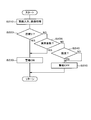
図7は、警報制御のメイン制御のフローチャートであり、
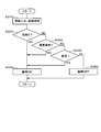
図8は、第1の警報制御のフローチャートであり、
図9は、第2の警報制御のフローチャートであり、
図10は、第3の警報制御のフローチャートであり、
図11は、第2実施形態の第2の警報制御のフローチャートであり、
図12は、第3の警報制御のフローチャートである。
The above and other objects, features and advantages of the present disclosure will become more apparent from the following detailed description with reference to the accompanying drawings. The drawing
FIG. 1 is a block diagram illustrating an electrical configuration of the vehicle alarm device according to the first embodiment. FIG. 2 is a diagram (part 1) for explaining the control for determining the vehicle speed. FIG. 3 is a diagram (part 2) for explaining the control for determining the vehicle speed, FIG. 4 is a diagram showing a table of alarm on / off relations when the speed range of the vehicle speed is V≈0. FIG. 5 is a diagram showing a table of alarm on / off relationships when the vehicle speed range is 0 <V ≦ Vth. FIG. 6 is a diagram showing a table of alarm on / off relations when the speed range of the vehicle speed is Vth <V. FIG. 7 is a flowchart of the main control of the alarm control. FIG. 8 is a flowchart of the first alarm control, FIG. 9 is a flowchart of the second alarm control, FIG. 10 is a flowchart of the third alarm control, FIG. 11 is a flowchart of the second alarm control of the second embodiment, FIG. 12 is a flowchart of the third alarm control.
(第1実施形態)
以下、第1実施形態について、図1ないし図10を参照して説明する。本実施形態の車両用警報装置1は、図1に示すように、制御装置2と、車室内カメラ3と、車速検知部4と、報知部5と、操作入力部6を備えて構成されている。制御装置2は、車両用警報装置1全体を制御するものであり、車室内カメラ3により撮影された画像データを入力し、車速検知部4により検知された車速信号を入力し、操作入力部6により入力された操作信号を入力し、報知部5を駆動制御する機能を有する。制御装置2は、居眠り検知部、脇見検知部及び警報制御部としての各機能を有する。 (First embodiment)
Hereinafter, the first embodiment will be described with reference to FIGS. 1 to 10. As shown in FIG. 1, thevehicle alarm device 1 according to this embodiment includes a control device 2, a vehicle interior camera 3, a vehicle speed detection unit 4, a notification unit 5, and an operation input unit 6. Yes. The control device 2 controls the vehicle alarm device 1 as a whole, inputs image data captured by the vehicle interior camera 3, inputs a vehicle speed signal detected by the vehicle speed detection unit 4, and inputs the operation input unit 6 It has a function of inputting the operation signal input by, and driving and controlling the notification unit 5. The control device 2 has functions as a dozing detection unit, a side-view detection unit, and an alarm control unit.
以下、第1実施形態について、図1ないし図10を参照して説明する。本実施形態の車両用警報装置1は、図1に示すように、制御装置2と、車室内カメラ3と、車速検知部4と、報知部5と、操作入力部6を備えて構成されている。制御装置2は、車両用警報装置1全体を制御するものであり、車室内カメラ3により撮影された画像データを入力し、車速検知部4により検知された車速信号を入力し、操作入力部6により入力された操作信号を入力し、報知部5を駆動制御する機能を有する。制御装置2は、居眠り検知部、脇見検知部及び警報制御部としての各機能を有する。 (First embodiment)
Hereinafter, the first embodiment will be described with reference to FIGS. 1 to 10. As shown in FIG. 1, the
車室内カメラ3は、ドライバの顔周辺を連続的に撮影し、撮影した画像データを制御装置2へ送信する。制御装置2は、上記画像データを受信し、受信した画像データを画像認識処理することにより、例えばドライバの瞼の開度、ドライバの顔の向き、ドライバの視線の方向、ドライバの頭部の位置などを検出する。制御装置2は、上記各検出結果のデータに基づいて、ドライバの状態を推定する機能、即ち、DSM(Driver Status Monitor)としての機能を有する。
The vehicle interior camera 3 continuously captures the periphery of the driver's face, and transmits the captured image data to the control device 2. The control device 2 receives the image data and performs image recognition processing on the received image data, for example, the driver's eyelid opening, the driver's face direction, the driver's line-of-sight direction, and the driver's head position. Etc. are detected. The control device 2 has a function of estimating the state of the driver based on the data of each detection result, that is, a function as DSM (Driver Status Monitor).
本実施形態の場合、制御装置2は、ドライバの状態としてドライバの不安全状態、例えば居眠り、脇見、不安全な姿勢、即ち、異常姿勢などを判定する機能を有している。制御装置2は、ドライバの状態として例えば「居眠り」を判定する場合、時系列を考慮したドライバの瞼の開度、即ち、個人の瞼の開度平均に対する相対値や、ドライバの顔の表情等で、居眠り状態であるか否かを判定するように構成されている。尚、この居眠りの判定制御については、周知技術の判定制御を適宜流用することが好ましい。
In the case of the present embodiment, the control device 2 has a function of determining an unsafe state of the driver as a driver state, for example, falling asleep, looking aside, an unsafe posture, that is, an abnormal posture. For example, when determining “sleeping” as the driver state, the control device 2 considers a time series of the driver's eyelid opening, that is, a relative value with respect to the average eyelid opening of the individual, the facial expression of the driver, and the like. Thus, it is configured to determine whether or not it is a doze state. In addition, about this dozing determination control, it is preferable to appropriately use the determination control of a known technique.
また、制御装置2は、ドライバの状態として例えば「脇見」を判定する場合、ドライバの顔の向きと、ドライバの視線の方向と、それらの持続時間で判定している。具体的には、ドライバの顔の向き及び視線の方向が、正面に対して、例えば30度以上横を向いている状態が、例えば2秒以上持続しているとき、ドライバが脇見していると判定する。尚、本実施形態では、ドライバの脇見を判定するに際して、ドライバの顔の向き+ドライバの視線の方向で判定するように構成したが、これに代えて、ドライバの顔の向きで判定するように構成しても良いし、ドライバの視線の方向で判定するように構成しても良い。
In addition, when determining, for example, “aside look” as the driver state, the control device 2 determines the direction of the driver's face, the direction of the driver's line of sight, and their duration. Specifically, when the driver's face direction and line-of-sight direction are sideways with respect to the front, for example, 30 degrees or more, for example, for 2 seconds or longer, the driver is looking aside. judge. In the present embodiment, when the driver's side look is determined, the determination is made based on the driver's face direction + the driver's line of sight. Instead, the driver's face direction is determined. You may comprise, and you may comprise so that it may determine with the direction of a driver | operator's eyes | visual_axis.
また、制御装置2は、ドライバの状態として例えば異常姿勢、即ち、不安全姿勢を判定する機能を有している。制御装置2は、ドライバの頭部位置が予め設定された異常姿勢判定用領域、即ち、頭部位置の正常位置を示す領域から外れた状態が、設定時間例えば2秒以上続いたときに、ドライバの姿勢が異常姿勢であると判定している。
Also, the control device 2 has a function of determining, for example, an abnormal posture, that is, an unsafe posture as a driver state. When the head position of the driver deviates from the preset abnormal posture determination area, that is, the area indicating the normal position of the head position continues for a set time, for example, 2 seconds or more, the control device 2 Is determined to be an abnormal posture.
車速検知部4は、車両の車速センサから出力される車速パルス、または、GPS(Global Positioning System)受信機から出力されるGPS信号に基づいて車速を検出し、検出した車速信号を制御装置2へ送信する。
The vehicle speed detection unit 4 detects the vehicle speed based on a vehicle speed pulse output from a vehicle speed sensor of the vehicle or a GPS signal output from a GPS (Global Positioning System) receiver, and sends the detected vehicle speed signal to the control device 2. Send.
報知部5は、スピーカと、このスピーカから警報音等を出力する音出力装置と、スピーカから警報メッセージ等の音声を出力する音声出力装置と、インストルメントパネルに設けられたディスプレイと、このディスプレイに警報メッセージ等を表示する表示制御装置とを備えて構成されている。操作入力部6は、ディスプレイの画面に設けられたタッチパネルや、ディスプレイの周辺部位に設けられたメカスイッチや、リモコン等を備えて構成されている。
The notification unit 5 includes a speaker, a sound output device that outputs an alarm sound and the like from the speaker, a sound output device that outputs sound such as an alarm message from the speaker, a display provided on the instrument panel, And a display control device for displaying an alarm message or the like. The operation input unit 6 includes a touch panel provided on a display screen, a mechanical switch provided in a peripheral part of the display, a remote controller, and the like.
本実施形態では、制御装置2は、ドライバの居眠りや脇見の警報を、車速に応じて警報したり、警報しなかったりする制御を実施している。そのため、制御装置2は、車速Vが予め設定された閾値Vth例えば10km/hを越えているかどうか、具体的には、車速Vの速度レンジが、0<V≦Vth、Vth<V、V≒0のいずれであるかを正確に判断し、誤検出を防止する必要がある。
In the present embodiment, the control device 2 performs a control of warning or not warning the driver of falling asleep or looking aside according to the vehicle speed. Therefore, the control device 2 determines whether or not the vehicle speed V exceeds a preset threshold value Vth, for example, 10 km / h, specifically, the speed range of the vehicle speed V is 0 <V ≦ Vth, Vth <V, V≈ It is necessary to accurately determine which is 0 and to prevent erroneous detection.
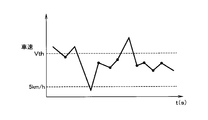
そこで、本実施形態においては、制御装置2は、車速の誤検出を防止するために、次のような制御を実施している。例えば、図2に示すように、車速を100ms毎に10回、即ち、1s間検出し、10回の車速検出値の多数が、0の近傍である例えば5km/hとVthとの間に存在する場合に、速度レンジが、0<V≦Vthであると判定する。即ち、検出回数が少ないVthを越える検出値や、検出回数が少ない5km/h未満の検出値は、ノイズとして無視する。
Therefore, in the present embodiment, the control device 2 performs the following control in order to prevent erroneous detection of the vehicle speed. For example, as shown in FIG. 2, the vehicle speed is detected 10 times every 100 ms, that is, for 1 s, and many of the detected vehicle speed values are between 0 km, for example, between 5 km / h and Vth. When it is determined that the speed range is 0 <V ≦ Vth. That is, the detection value exceeding Vth with a small number of detections or the detection value with a small number of detections of less than 5 km / h is ignored as noise.
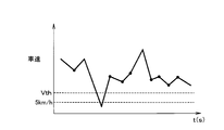
また、図3に示すように、車速を100ms毎に10回、即ち、1s間検出し、10回の車速検出値の多数が、Vthを越えている場合に、速度レンジが、Vth<Vであると判定する。即ち、検出回数が少ないVth以下の検出値は、ノイズとして無視する。
Further, as shown in FIG. 3, when the vehicle speed is detected 10 times every 100 ms, that is, for 1 s, and many of the detected vehicle speed values exceed Vth, the speed range is Vth <V. Judge that there is. That is, a detection value of Vth or less with a small detection count is ignored as noise.
また、V≒0を判定するに際しては、車速を100ms毎に10回、即ち、1s間検出し、10回の車速検出値の多数が、0の近傍である例えば5km/h未満である場合に、速度レンジが、V≒0であると判定する。即ち、検出回数が少ない5km/h以上の検出値は、ノイズとして無視する。
In determining V≈0, when the vehicle speed is detected 10 times every 100 ms, that is, for 1 s, and many of the detected vehicle speed values in the 10 times are near 0, for example, less than 5 km / h. The speed range is determined to be V≈0. That is, a detection value of 5 km / h or more with a small number of detections is ignored as noise.
また、車速を100ms毎に10回、即ち、1s間検出したときに、10回の車速検出値のうちの、V≒0、即ち、5km/h未満の車速検出値が例えば2回であり、0<V≦Vthの車速検出値が例えば3回であり、Vth<Vの車速検出値が例えば5回であった場合には、車速検出値が最大回数の速度レンジVth<Vを、車速として判定する。
Further, when the vehicle speed is detected 10 times every 100 ms, that is, for 1 s, the vehicle speed detection value of V≈0, that is, less than 5 km / h out of 10 vehicle speed detection values is, for example, 2 times, When the vehicle speed detection value of 0 <V ≦ Vth is, for example, 3 times and the vehicle speed detection value of Vth <V is, for example, 5 times, the speed range Vth <V with the maximum vehicle speed detection value is set as the vehicle speed. judge.
尚、上述した車速の誤検出防止制御を、制御装置2において実施したが、これに代えて、車速検知部4側において実施するように構成しても良い。また、車速を100ms毎に10回検出するように構成したが、これに限られるものではなく、例えば車速を1s毎に10回、即ち、10秒間検出するように構成しても良く、車速の検出タイミングや検出回数や検出時間等は、適宜変更することが可能である。また、チャタリング防止機能を入れる、即ち、例えば1度だけ検出された車速の速度レンジは無視するように構成しても良い。
In addition, although the erroneous detection prevention control of the vehicle speed mentioned above was implemented in the control apparatus 2, it may replace with this and you may comprise so that it may implement in the vehicle speed detection part 4 side. The vehicle speed is detected 10 times every 100 ms. However, the present invention is not limited to this. For example, the vehicle speed may be detected 10 times every 1 s, that is, for 10 seconds. The detection timing, the number of detections, the detection time, and the like can be changed as appropriate. Further, a chattering prevention function may be provided, that is, the speed range of the vehicle speed detected only once may be ignored.
また、車速の閾値Vthは、10km/hよりも大きい値、または、10km/hよりも小さい値に、ドライバ、ユーザまたは運行管理者等によって例えば操作入力部6を操作して変更可能なように構成されている。尚、閾値Vthの変更操作は、運転終了時等に行なうことが好ましい。
Further, the vehicle speed threshold Vth can be changed to a value larger than 10 km / h or a value smaller than 10 km / h by operating the operation input unit 6, for example, by a driver, a user, an operation manager, or the like. It is configured. The threshold Vth changing operation is preferably performed at the end of the operation.
さて、本実施形態においては、画像認識処理結果に基づくドライバの居眠り警報・脇見警報は、誤警報が発生する可能性があるため、車速判定条件を加味することにより、誤警報の発生を極力抑制している。即ち、ドライバの居眠りの検知結果、ドライバの脇見の検知結果、または、車速の検知結果に基づいて、警報を実行する、または、警報を実行しないを制御している。具体的には、車速Vを3つの速度レンジ、V≒0、0<V≦Vth、Vth<Vに分けて、居眠り警報または脇見警報の各実施条件を設定している。
By the way, in this embodiment, the driver's doze alarm / armpit alarm based on the image recognition processing result may generate a false alarm. Therefore, the generation of the false alarm is suppressed as much as possible by taking the vehicle speed determination condition into consideration. doing. That is, based on the detection result of the driver's falling asleep, the detection result of the driver's looking aside, or the detection result of the vehicle speed, control is performed to execute the alarm or not to execute the alarm. Specifically, the vehicle speed V is divided into three speed ranges, V≈0, 0 <V ≦ Vth, and Vth <V, and the execution conditions for the dozing alarm or the aside alarm are set.
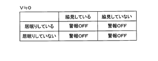
まず、速度レンジが、V≒0の場合には、図4の表に示すように、居眠りしている/居眠りしていない、脇見している/脇見していないにかかわらず、警報が行なわれないように構成されている。
First, when the speed range is V≈0, as shown in the table of FIG. 4, an alarm is issued regardless of whether you are asleep / not asleep, aside or not aside. Is configured to not.
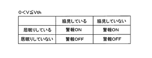
次に、速度レンジが、0<V≦Vthの場合には、図5の表に示すように、居眠りしているときには、脇見の有無にかかわらず、警報が行なわれる。そして、居眠りしていないときには、脇見の有無にかかわらず、警報が行なわれないようになっている。即ち、本速度レンジの場合、居眠りしないで脇見しているときには、警報が実行されないように構成されている。
Next, when the speed range is 0 <V ≦ Vth, as shown in the table of FIG. 5, an alarm is issued regardless of the presence or absence of looking aside when sleeping. When the person is not asleep, the alarm is not performed regardless of the presence or absence of the aside. That is, in the case of this speed range, the alarm is not executed when looking aside without falling asleep.
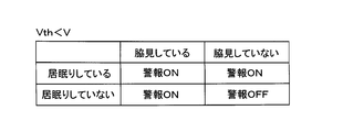
また、速度レンジが、Vth<Vの場合には、図6の表に示すように、居眠りしているときには、脇見の有無にかかわらず、警報が行なわれる。そして、居眠りしていないときには、脇見しているときに、警報が行なわれ、脇見していないときには、警報が行なわれないようになっている。即ち、本速度レンジの場合、居眠りしないで脇見している場合、警報が実行されるように構成されている。
Further, when the speed range is Vth <V, as shown in the table of FIG. 6, an alarm is issued regardless of the presence or absence of looking aside when sleeping. When not asleep, an alarm is given when looking aside, and when not looking aside, no alarm is given. That is, in the case of this speed range, the alarm is executed when looking aside without falling asleep.
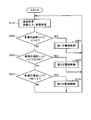
次に、上記構成の警報制御について、図7ないし図10を参照して説明する。図7ないし図10のフローチャートは、制御装置2の制御の内容を示す。まず、図7のステップS10においては、制御装置2は、車速検知部4から車速検知信号を入力し、入力した車速検知信号に基づいて前記した誤検出防止制御を実行し、車速Vが前記3つの速度レンジのいずれに入るかを判定する、即ち、車速を取得する。そして、制御装置2は、車室内カメラ3から画像データを入力し、入力した画像データを画像認識処理することにより、ドライバの状態、具体的には、ドライバが居眠りしているか否か、及び、ドライバが脇見しているか否かを判定し、判定結果を制御装置2の内部のメモリに記憶する。このドライバの画像処理は、ドライバ状態判断制御に相当している。
Next, the alarm control with the above configuration will be described with reference to FIGS. 7 to 10 show the contents of control by the control device 2. First, in step S10 of FIG. 7, the control device 2 inputs a vehicle speed detection signal from the vehicle speed detection unit 4, executes the above-described erroneous detection prevention control based on the input vehicle speed detection signal, and the vehicle speed V is 3 One of the two speed ranges is determined, that is, the vehicle speed is acquired. Then, the control device 2 inputs image data from the vehicle interior camera 3 and performs image recognition processing on the input image data, so that the driver state, specifically, whether the driver is asleep or not, It is determined whether or not the driver is looking aside, and the determination result is stored in a memory inside the control device 2. This driver image processing corresponds to driver state determination control.
続いて、ステップS20へ進み、車速Vの速度レンジが、V≒0であるか否かを判断する。ここで、速度レンジが、V≒0であるときには(YES)、ステップS50へ進み、第1の警報制御を実行する。この第1の警報制御については、後述する。また、上記ステップS20において、速度レンジが、V≒0でないときには(NO)、ステップS30へ進む。
Subsequently, the process proceeds to step S20, and it is determined whether or not the speed range of the vehicle speed V is V≈0. Here, when the speed range is V≈0 (YES), the process proceeds to step S50, and the first alarm control is executed. This first alarm control will be described later. In step S20, when the speed range is not V≈0 (NO), the process proceeds to step S30.
ステップS30においては、車速Vの速度レンジが、0<V≦Vthであるか否かを判断する。ここで、速度レンジが、0<V≦Vthであるときには(YES)、ステップS60へ進み、第2の警報制御を実行する。この第2の警報制御については、後述する。また、上記ステップS30において、速度レンジが、0<V≦Vthでないときには(NO)、ステップS40へ進む。
In step S30, it is determined whether or not the speed range of the vehicle speed V is 0 <V ≦ Vth. Here, when the speed range is 0 <V ≦ Vth (YES), the process proceeds to step S60, and the second alarm control is executed. This second alarm control will be described later. In step S30, when the speed range is not 0 <V ≦ Vth (NO), the process proceeds to step S40.
ステップS40においては、車速Vの速度レンジが、Vth<Vであるか否かを判断する。ここで、速度レンジが、Vth<Vであるときには(YES)、ステップS70へ進み、第3の警報制御を実行する。この第3の警報制御については、後述する。また、上記ステップS40において、速度レンジが、Vth<Vでないときには(NO)、ステップS10へ戻り、上述した処理を繰り返し実行するようになっている。本実施形態では、図7の制御、即ち、車速判断制御は、予め決められた周期で繰り返し実行されるように構成されている。
In step S40, it is determined whether or not the speed range of the vehicle speed V is Vth <V. Here, when the speed range is Vth <V (YES), the process proceeds to step S70 to execute the third alarm control. This third alarm control will be described later. In step S40, when the speed range is not Vth <V (NO), the process returns to step S10 and the above-described processing is repeatedly executed. In the present embodiment, the control of FIG. 7, that is, the vehicle speed determination control is configured to be repeatedly executed at a predetermined cycle.
次に、ステップS50の第1の警報制御について、図8を参照して説明する。図8のステップS110においては、制御装置2は、車室内カメラ3から画像データを入力し、入力した画像データを画像処理することにより、ドライバの状態、具体的には、ドライバが居眠りしているか否か、及び、ドライバが脇見しているか否かを判定し、判定結果を制御装置2の内部のメモリに記憶する。尚、このドライバの画像処理、即ち、ドライバ状態判断制御については、図7のステップS10において、既に実行しているので、ステップS110の処理は省略しても良い。また、ステップS110において、画像処理を実行するように構成するのであれば、図7のステップS10の画像処理を省略するように構成しても良い。
Next, the first alarm control in step S50 will be described with reference to FIG. In step S110 of FIG. 8, the control device 2 inputs image data from the in-vehicle camera 3 and performs image processing on the input image data, so that the driver state, specifically, whether the driver is asleep. Whether or not the driver is looking aside is determined, and the determination result is stored in a memory inside the control device 2. Note that this driver image processing, that is, driver state determination control, has already been executed in step S10 in FIG. 7, and therefore the processing in step S110 may be omitted. Further, if the image processing is configured to be executed in step S110, the image processing in step S10 in FIG. 7 may be omitted.
続いて、ステップS120へ進み、ドライバが居眠りしているか否かを判断する。ここで、ドライバが居眠りしているときには(YES)、ステップS130へ進み、ドライバが脇見しているか否かを判断する。ここで、ドライバが脇見しているときには(YES)、ステップS140へ進み、居眠り・脇見の警報をオフする、即ち、警報を実行しない。これにより、第1の警報制御を終了し、図7のメイン制御に戻る。
Subsequently, the process proceeds to step S120, and it is determined whether or not the driver is asleep. If the driver is asleep (YES), the process proceeds to step S130 to determine whether the driver is looking aside. If the driver is looking aside (YES), the process proceeds to step S140 to turn off the dozing / side-arming alarm, that is, the alarm is not executed. Thereby, the first alarm control is terminated, and the process returns to the main control in FIG.
また、上記ステップS120において、ドライバが居眠りしていないときには(NO)、ステップS140へ進み、居眠り・脇見の警報をオフし、第1の警報制御を終了する。
In step S120, when the driver is not asleep (NO), the process proceeds to step S140 to turn off the doze / aside alarm and end the first alarm control.
また、上記ステップS130において、ドライバが脇見していないときには(NO)、ステップS140へ進み、居眠り・脇見の警報をオフし、第1の警報制御を終了する。
In step S130, when the driver is not looking aside (NO), the process proceeds to step S140 to turn off the dozing / sidearm alarm and end the first alarm control.
尚、第1の警報制御においては、居眠りの有無、脇見の有無にかかわらず、警報を実行しないので、ステップS110からステップS130までの処理を省略し、ステップS140だけを実行するように構成しても良い。
In the first alarm control, the alarm is not executed regardless of whether the patient is asleep or looking aside. Therefore, the process from step S110 to step S130 is omitted, and only step S140 is executed. Also good.
次に、ステップS60の第2の警報制御について、図9を参照して説明する。図9のステップS210においては、制御装置2は、車室内カメラ3から画像データを入力し、入力した画像データを画像処理することにより、ドライバの状態、具体的には、ドライバが居眠りしているか否か、及び、ドライバが脇見しているか否かを判定し、判定結果を制御装置2の内部のメモリに記憶する。尚、このドライバの画像処理、即ち、ドライバ状態判断制御については、図7のステップS10において、既に実行しているので、ステップS210の処理は省略しても良い。また、ステップS210の画像処理を実行するように構成するのであれば、図7のステップS10の画像処理を省略するように構成しても良い。
Next, the second alarm control in step S60 will be described with reference to FIG. In step S210 of FIG. 9, the control device 2 inputs image data from the vehicle interior camera 3, and performs image processing on the input image data, so that the state of the driver, specifically, whether the driver is asleep. Whether or not the driver is looking aside is determined, and the determination result is stored in a memory inside the control device 2. Note that the image processing of the driver, that is, driver state determination control has already been performed in step S10 in FIG. 7, and therefore the processing in step S210 may be omitted. Further, if it is configured to execute the image processing in step S210, the image processing in step S10 in FIG. 7 may be omitted.
続いて、ステップS220へ進み、ドライバが居眠りしているか否かを判断する。ここで、ドライバが居眠りしているときには(YES)、ステップS230へ進み、居眠り・脇見の警報をオンする、即ち、警報を実行する。この場合、制御装置2は、報知部5を駆動制御することにより、スピーカから居眠りを警告する警報音や居眠りを警告する警報音声等を出力したり、ディスプレイに居眠りを警告する警報メッセージを表示したりする。
これにより、第2の警報制御を終了し、図7のメイン制御に戻る。 Then, it progresses to step S220 and it is judged whether the driver is dozing. Here, when the driver is dozing (YES), the process proceeds to step S230, and the dozing / side-arming alarm is turned on, that is, the alarm is executed. In this case, thecontrol device 2 controls the driving of the notification unit 5 to output an alarm sound for warning dozing, an alarm sound for warning dozing from the speaker, or display an alarm message for warning dozing on the display. Or
Thereby, the second alarm control is terminated, and the process returns to the main control in FIG.
これにより、第2の警報制御を終了し、図7のメイン制御に戻る。 Then, it progresses to step S220 and it is judged whether the driver is dozing. Here, when the driver is dozing (YES), the process proceeds to step S230, and the dozing / side-arming alarm is turned on, that is, the alarm is executed. In this case, the
Thereby, the second alarm control is terminated, and the process returns to the main control in FIG.
また、上記ステップS220において、ドライバが居眠りしていないときには(NO)、ステップS240へ進み、ドライバが脇見しているか否かを判断する。ここで、ドライバが脇見しているときには(YES)、ステップS250へ進み、居眠り・脇見の警報をオフする、即ち、警報を実行しない。これにより、第2の警報制御を終了し、図7のメイン制御に戻る。
In step S220, when the driver is not asleep (NO), the process proceeds to step S240, and it is determined whether the driver is looking aside. Here, when the driver is looking aside (YES), the process proceeds to step S250, where the dozing / aside look alarm is turned off, that is, the alarm is not executed. Thereby, the second alarm control is terminated, and the process returns to the main control in FIG.
また、上記ステップS240において、ドライバが脇見していないときには(NO)、この場合も、ステップS250へ進み、居眠り・脇見の警報をオフし、第2の警報制御を終了する。
In step S240, when the driver is not looking aside (NO), the process proceeds to step S250 in this case, the dozing / side-arming alarm is turned off, and the second alarm control is terminated.
尚、第2の警報制御においては、居眠りしていないときには、脇見の有無にかかわらず、警報を実行しないので、ステップS240の処理を省略し、ステップS220にて「NO」のときは、ステップS250を実行するように構成しても良い。
In the second alarm control, when the person is not asleep, the alarm is not executed regardless of the presence or absence of looking aside. Therefore, the process of step S240 is omitted, and when “NO” in step S220, the process proceeds to step S250. May be configured to execute.
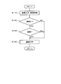
次に、ステップS70の第3の警報制御について、図10を参照して説明する。図10のステップS310においては、制御装置2は、車室内カメラ3から画像データを入力し、入力した画像データを画像処理することにより、ドライバの状態、具体的には、ドライバが居眠りしているか否か、及び、ドライバが脇見しているか否かを判定し、判定結果を制御装置2の内部のメモリに記憶する。尚、このドライバの画像処理、即ち、ドライバ状態判断制御については、図7のステップS10において、既に実行しているので、ステップS310の処理は省略することが可能である。また、ステップS310の画像処理を実行するように構成するのであれば、図7のステップS10の画像処理を省略するように構成しても良い。
Next, the third alarm control in step S70 will be described with reference to FIG. In step S310 of FIG. 10, the control device 2 inputs image data from the vehicle interior camera 3, and performs image processing on the input image data, so that the driver state, specifically, whether the driver is asleep. Whether or not the driver is looking aside is determined, and the determination result is stored in a memory inside the control device 2. Note that the image processing of the driver, that is, driver state determination control has already been performed in step S10 in FIG. 7, and therefore the processing in step S310 can be omitted. Further, if it is configured to execute the image processing in step S310, the image processing in step S10 in FIG. 7 may be omitted.
続いて、ステップS320へ進み、ドライバが居眠りしているか否かを判断する。ここで、ドライバが居眠りしているときには(YES)、ステップS330へ進み、居眠り・脇見の警報をオンする、即ち、警報を実行する。この場合、制御装置2は、報知部5を駆動制御することにより、スピーカから居眠りを警告する警報音や居眠りを警告する警報音声等を出力したり、ディスプレイに居眠りを警告する警報メッセージを表示したりする。
これにより、第3の警報制御を終了し、図7のメイン制御に戻る。 Then, it progresses to step S320 and it is judged whether the driver is dozing. Here, when the driver is dozing (YES), the process proceeds to step S330, and the dozing / side-arming alarm is turned on, that is, the alarm is executed. In this case, thecontrol device 2 controls the driving of the notification unit 5 to output an alarm sound for warning dozing, an alarm sound for warning dozing from the speaker, or display an alarm message for warning dozing on the display. Or
As a result, the third alarm control is terminated and the process returns to the main control in FIG.
これにより、第3の警報制御を終了し、図7のメイン制御に戻る。 Then, it progresses to step S320 and it is judged whether the driver is dozing. Here, when the driver is dozing (YES), the process proceeds to step S330, and the dozing / side-arming alarm is turned on, that is, the alarm is executed. In this case, the
As a result, the third alarm control is terminated and the process returns to the main control in FIG.
また、上記ステップS320において、ドライバが居眠りしていないときには(NO)、ステップS340へ進み、ドライバが脇見しているか否かを判断する。ここで、ドライバが脇見しているときには(YES)、ステップS330へ進み、居眠り・脇見の警報をオンする、即ち、警報を実行する。これにより、第3の警報制御を終了し、図7のメイン制御に戻る。
In step S320, if the driver is not asleep (NO), the process proceeds to step S340 to determine whether the driver is looking aside. Here, when the driver is looking aside (YES), the process proceeds to step S330 to turn on the dozing / side-arming alarm, that is, execute the alarm. As a result, the third alarm control is terminated and the process returns to the main control in FIG.
また、上記ステップS340において、ドライバが脇見していないときには(NO)、この場合も、ステップS350へ進み、居眠り・脇見の警報をオフし、即ち、警報を実行しない。これにより、第3の警報制御を終了し、図7のメイン制御に戻る。
In step S340, when the driver is not looking aside (NO), in this case as well, the process proceeds to step S350, where the dozing / sidearm alarm is turned off, that is, the alarm is not executed. As a result, the third alarm control is terminated and the process returns to the main control in FIG.
尚、本実施形態では、図8、図9、図10の各制御、即ち、ドライバ状態判断制御は、予め決められた周期で繰り返し実行されるように構成されている。そして、図7の車速判断制御と、図8、図9、図10の各ドライバ状態判断制御は、同期しながら繰り返し実行されるように構成されている。
In the present embodiment, each control in FIG. 8, FIG. 9, and FIG. 10, that is, the driver state determination control is configured to be repeatedly executed at a predetermined cycle. The vehicle speed determination control in FIG. 7 and each driver state determination control in FIGS. 8, 9, and 10 are configured to be repeatedly executed in synchronization.
また、上記各実施形態では、車速判断制御を先に実行し、ドライバ状態判断制御、即ち、ドライバの居眠りや脇見等の判断制御をその後で実行するように構成したが、これに代えて、ドライバ状態判断制御を先に実行し、車速判断制御をその後で実行するように構成しても良い。このように構成しても、ほぼ同じ作用効果を得ることができる。
Further, in each of the above embodiments, the vehicle speed determination control is executed first, and the driver state determination control, that is, the determination control such as the driver's doze or looking aside is executed thereafter. The state determination control may be executed first, and the vehicle speed determination control may be executed thereafter. Even if comprised in this way, the substantially same effect can be acquired.
このような構成の本実施形態においては、ドライバの居眠りまたは脇見が検知されたときに、報知部により警報を実行させるものであって、ドライバの居眠りの検知結果、ドライバの脇見の検知結果または車速の検知結果に基づいて報知部による警報の実行を制御するように構成した。この構成によれば、ドライバが居眠りしたときや脇見したときに警報することができ、しかも、警報が必要でないときには、警報を実行しないように構成できるので、ドライバが警報を煩わしいと感じる事態を極力防止することができる。
In the present embodiment having such a configuration, when the driver's snoozing or looking aside is detected, an alarm is executed by the notification unit, and the driver's snoozing detection result, the driver's sniffing detection result or the vehicle speed is detected. Based on the detection result, the execution of the alarm by the notification unit is controlled. According to this configuration, when the driver falls asleep or looks aside, it can be configured not to execute the alarm when the alarm is not necessary, so that the situation where the driver feels annoying the alarm is as much as possible. Can be prevented.
また、本実施形態では、閾値Vthを、変更可能なように構成したので、警報するかいないかの判定レベルを、ドライバ、即ち、ユーザの感覚にあう様にカスタマイズ可能になることから、誤警報が少なくなり、ドライバの煩わしさを低減することができる。従って、従来より、ユーザビリティを高めることができる。
In the present embodiment, since the threshold value Vth is configured to be changeable, the determination level of whether or not to issue an alarm can be customized to suit the feeling of the driver, that is, the user. And the troublesomeness of the driver can be reduced. Therefore, usability can be improved as compared with the prior art.
更に、本実施形態では、車速が前記閾値Vth以下のときには、ドライバの居眠りを検知したときに、警報を実行させ、ドライバの脇見を検知しても、警報を実行させないように構成した。この構成によれば、駐車場で駐車位置等を捜すために車両が超低速で移動しているようなときには、警報が実行されなくなるので、ドライバが警報を煩わしいと感じるおそれを無くすことができる。
Furthermore, in the present embodiment, when the vehicle speed is equal to or lower than the threshold value Vth, an alarm is executed when the driver's drowsiness is detected, and the alarm is not executed even when the driver's side aside is detected. According to this configuration, when the vehicle is moving at an extremely low speed in order to search for a parking position or the like in the parking lot, the alarm is not executed, so that it is possible to eliminate the possibility that the driver feels the alarm troublesome.
また、本実施形態では、車速が前記閾値Vthよりも大きいときには、ドライバの居眠りを検知したとき、または、ドライバの脇見を検知したときに、警報を実行させるように構成した。この構成によれば、車両が通常の車速で走行しているときには、居眠りや脇見が検知されたときに、警報が実行されるので、居眠り運転や脇見運転を防止することができる。
Further, in the present embodiment, when the vehicle speed is higher than the threshold value Vth, a warning is executed when a driver's drowsiness is detected or when a driver's aside is detected. According to this configuration, when the vehicle is traveling at a normal vehicle speed, an alarm is executed when a drowsiness or a look-aside is detected, so that a drowsy operation or a look-aside operation can be prevented.
また、本実施形態では、車速が0または0に近いときには、ドライバの居眠りを検知しても、ドライバの脇見を検知しても、警報を実行させないように構成したので、車速が0または0に近いときには、居眠りや脇見の警報が実行されなくなるので、ドライバが警報を煩わしいと感じるおそれを無くすことができる。
Further, in the present embodiment, when the vehicle speed is 0 or close to 0, the alarm is not executed even if the driver's doze is detected or the driver's aside is detected, so the vehicle speed is 0 or 0. When close, alarms for falling asleep or looking aside are not executed, so that the driver can feel that the alarm is bothersome.
(第2実施形態)
図11及び図12は、第2実施形態を示すものである。尚、第1実施形態と同一構成には、同一符号を付している。第2実施形態では、ドライバの居眠りや脇見の検知に加えて、ドライバの異常姿勢を検知して警報するように構成したものである。第1実施形態のステップS60の第2の警報制御、即ち、図9のフローチャートと、ステップS70の第3の警報制御、即ち、図10のフローチャートとを、次に説明するように変更した。 (Second Embodiment)
11 and 12 show a second embodiment. In addition, the same code | symbol is attached | subjected to the same structure as 1st Embodiment. In the second embodiment, in addition to detecting the driver's snoozing or looking aside, an abnormal posture of the driver is detected and an alarm is issued. The second alarm control of Step S60 of the first embodiment, that is, the flowchart of FIG. 9, and the third alarm control of Step S70, that is, the flowchart of FIG. 10 are changed as described below.
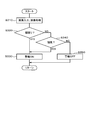
まず、第2実施形態の第2の警報制御について、図11を参照して説明する。図11のステップS210、S220、S230の各処理は、第1実施形態と同様に実行する。ステップS220において、ドライバが居眠りしていないときには(NO)、ステップS235へ進み、ドライバが異常姿勢であるか否かを判断する。尚、ドライバの異常姿勢の検知処理は、ステップS210または図7のステップS10の画像処理、即ち、ドライバ状態判断制御において実行され、検知結果が制御装置2の内部のメモリに記憶されるように構成されている。
First, the second alarm control of the second embodiment will be described with reference to FIG. Each process of step S210, S220, and S230 of FIG. 11 is performed similarly to 1st Embodiment. In step S220, when the driver is not asleep (NO), the process proceeds to step S235, and it is determined whether or not the driver is in an abnormal posture. The abnormal posture detection process of the driver is executed in the image processing of step S210 or step S10 of FIG. 7, that is, driver state determination control, and the detection result is stored in a memory inside the control device 2. Has been.
上記ステップS235において、ドライバが異常姿勢であるときには(YES)、ステップS230へ進み、警報をオンする、即ち、居眠り・脇見・異常姿勢の警報を実行する。また、上記ステップS235において、ドライバが異常姿勢でないときには(NO)、ステップS240へ進み、ドライバが脇見しているか否かを判断する。尚、ステップS240、S250の各処理は、第1実施形態と同様に実行する。
If it is determined in step S235 that the driver is in an abnormal posture (YES), the process proceeds to step S230, where an alarm is turned on, that is, a doze / aside / abnormal posture alarm is executed. In step S235, when the driver is not in an abnormal posture (NO), the process proceeds to step S240, and it is determined whether the driver is looking aside. In addition, each process of step S240 and S250 is performed similarly to 1st Embodiment.
次に、第2実施形態の第3の警報制御について、図12を参照して説明する。図12のステップS310、S320、S330の各処理は、第1実施形態と同様に実行する。ステップS320において、ドライバが居眠りしていないときには(NO)、ステップS335へ進み、ドライバが異常姿勢であるか否かを判断する。尚、ドライバの異常姿勢の検知処理は、ステップS310または図7のステップS10の画像処理、即ち、ドライバ状態判断制御において実行され、検知結果が制御装置2の内部のメモリに記憶されるように構成されている。
Next, the third alarm control of the second embodiment will be described with reference to FIG. Each process of step S310, S320, and S330 of FIG. 12 is performed similarly to 1st Embodiment. In step S320, when the driver is not asleep (NO), the process proceeds to step S335, and it is determined whether or not the driver is in an abnormal posture. The abnormal posture detection process of the driver is executed in the image processing in step S310 or step S10 of FIG. 7, that is, in the driver state determination control, and the detection result is stored in the internal memory of the control device 2. Has been.
上記ステップS335において、ドライバが異常姿勢であるときには(YES)、ステップS330へ進み、警報をオンする、即ち、居眠り・脇見・異常姿勢の警報を実行する。また、上記ステップS335において、ドライバが異常姿勢でないときには(NO)、ステップS340へ進み、ドライバが脇見しているか否かを判断する。尚、ステップS340、S350の各処理は、第1実施形態と同様に実行する。
In step S335, when the driver is in an abnormal posture (YES), the process proceeds to step S330, where an alarm is turned on, that is, a doze / aside / abnormal posture alarm is executed. In step S335, when the driver is not in an abnormal posture (NO), the process proceeds to step S340 to determine whether the driver is looking aside. In addition, each process of step S340 and S350 is performed similarly to 1st Embodiment.
尚、上述した以外の第2実施形態の構成は、第1実施形態の構成と同じ構成となっている。従って、第2実施形態においても、第1実施形態と、ほぼ同じ作用効果を得ることができる。特に、第2実施形態では、ドライバの異常姿勢を検知して警報するように構成したので、ドライバの姿勢が異常であるときに、その姿勢異常をドライバに注意することができ、ドライバが正しい姿勢をとるように促すことができる。
The configuration of the second embodiment other than that described above is the same as the configuration of the first embodiment. Therefore, in the second embodiment, substantially the same operational effects as in the first embodiment can be obtained. In particular, the second embodiment is configured to detect and warn of the driver's abnormal posture, so that when the driver's posture is abnormal, the driver can be aware of the posture abnormality, and the driver's correct posture Can be encouraged to take
尚、上記各実施形態では、閾値Vthの初期値、即ち、デフォルトを10km/hに設定したが、他の速度に設定しても良い。また、閾値Vthの変更については、上記各実施形態では、ユーザまたは運行管理者等によって変更可能な構成としたが、これに限られるものではなく、例えば次のように構成しても良い。
In each of the above embodiments, the initial value of the threshold value Vth, that is, the default is set to 10 km / h. However, other speeds may be set. The threshold value Vth can be changed by the user or the operation manager in each of the above embodiments. However, the present invention is not limited to this. For example, the threshold value Vth may be configured as follows.
車両の運転終了後において、ドライバから警報に対する煩わしさの情報を入力してもらい、入力された煩わしさの情報に基づいてドライバ毎に閾値Vthを調節するように構成した。具体的には、車両の運転が終わり、ドライバが降車する際に、例えば「警報の頻度は煩わしかったですか?」とディスプレイの画面に表示する。ここで、ドライバが操作入力部6の例えばタッチパネルを操作して「YES」または「NO」を選択すると、選択結果に応じて閾値Vthが変更されることにより、次回の運転時の警報処理に反映されるように構成されている。
After the driving of the vehicle is completed, the driver inputs the troublesome information for the alarm, and the threshold value Vth is adjusted for each driver based on the inputted troublesome information. Specifically, when the vehicle finishes driving and the driver gets off, for example, “Is the alarm frequency troublesome?” Is displayed on the display screen. Here, when the driver operates, for example, the touch panel of the operation input unit 6 to select “YES” or “NO”, the threshold value Vth is changed according to the selection result, which is reflected in the alarm processing at the next driving. It is configured to be.
例えば、ドライバが「YES」を選択した場合には、制御装置2は、閾値Vthを例えば5km/h増加させるように変更し、即ち、Vth=Vth+5km/hに設定し、変更した閾値Vthを、制御装置2の内部のメモリに保存する。反対に、ドライバが「NO」を選択した場合には、制御装置2は、閾値Vthは現在値に保持し、次回の運転時の警報処理に同じ値の閾値Vthを用いる。
For example, when the driver selects “YES”, the control device 2 changes the threshold value Vth to increase, for example, 5 km / h, that is, sets Vth = Vth + 5 km / h, and changes the threshold value Vth. Is stored in the internal memory of the control device 2. On the other hand, when the driver selects “NO”, the control device 2 keeps the threshold value Vth at the current value, and uses the threshold value Vth of the same value for the alarm processing at the next driving.
尚、「NO」が何回も続く場合には、居眠り等の未検出が多いことが想定されるため、閾値Vthを小さくするように変更して、居眠り等を検出し易くする。例えば5回の運転で連続して「NO」と応答された場合には、閾値Vthを例えば5km/h減少させるように変更し、即ち、Vth=Vth-5km/hに設定し、変更した閾値Vthを、制御装置2の内部のメモリ例えば不揮発性メモリに保存する。これにより、次回の運転において、検出制御の起動時に変更された閾値Vthが読み出され、検出制御に利用されるように構成されている。制御装置2及び操作入力部6は、閾値変更部としての機能を有している。
If “NO” continues many times, it is assumed that there are many undetected cases such as dozing. Therefore, the threshold value Vth is changed to make it easier to detect dozing. For example, when “NO” is continuously responded in five operations, the threshold value Vth is changed to decrease, for example, 5 km / h, that is, Vth = Vth−5 km / h, and the changed threshold value Vth is stored in a memory inside the control device 2, for example, a nonvolatile memory. Thereby, in the next driving | operation, the threshold value Vth changed at the time of starting of detection control is read, and it is comprised so that it may utilize for detection control. The control device 2 and the operation input unit 6 have a function as a threshold value changing unit.
また、上記各実施形態において、車両の運転終了後に、警告の頻度等が適切であるかどうかをドライバからフィードバックする様な仕組みを組み込むように構成しても良い。このように構成すると、例えば警告の頻度等が適切であると応答されたときには、警報がユーザーの感覚に合っていることから、閾値Vthを変更しないで、そのまま維持するように構成することが好ましい。
Further, in each of the above embodiments, a mechanism may be incorporated in which, after the driving of the vehicle is finished, feedback from the driver whether or not the warning frequency is appropriate. With this configuration, for example, when a response is made that the warning frequency or the like is appropriate, it is preferable that the threshold value Vth be maintained as it is because the alarm matches the user's sense. .
また、上記各実施形態は、車両が渋滞中であるか否かを判定していないし、車両が渋滞中であることを判定した場合に対応する制御を実施していない。これに対して、車両が渋滞中であるか否かを判定し、渋滞中であると判定された場合、車速Vの速度レンジが、V≒0(0)となったときでも、警報をオフしないで、警報を続けるように構成することが好ましい。尚、車速検知部だけでは、渋滞を正確に判断することができないため、VICS(登録商標)通信することにより、渋滞情報を入手して、渋滞中であるか否かを判定するように構成することが好ましい。しかし、このように構成すると、他の装置との連携が必要になるため、製造コストが高くなるおそれがある。また、例えばGPS信号に基づく車両の位置情報から、車両が道路上に存在する場合には、警報をオフしないで、警報を続けるように構成するが、車両が道路上に存在しない場合には、警報はオフするように構成することも可能である。
Further, each of the above embodiments does not determine whether or not the vehicle is congested, and does not perform control corresponding to the case where it is determined that the vehicle is congested. On the other hand, it is determined whether or not the vehicle is congested. If it is determined that the vehicle is congested, the alarm is turned off even when the speed range of the vehicle speed V becomes V≈0 (0). However, it is preferable that the alarm is continued. Note that the vehicle speed detection unit alone cannot accurately determine the traffic jam. Therefore, the VICS (registered trademark) communication is used to obtain the traffic jam information and determine whether the traffic jam is occurring. It is preferable. However, when configured in this manner, it is necessary to cooperate with other devices, which may increase the manufacturing cost. Further, for example, from the position information of the vehicle based on the GPS signal, when the vehicle exists on the road, it is configured to continue the alarm without turning off the alarm, but when the vehicle does not exist on the road, The alarm can also be configured to turn off.
尚、上記各実施形態では、全体のシステム構成と、居眠り等の検出アルゴリズムとを簡素化するために、車速Vの速度レンジが、V≒0となったときに、車両が停車中であるか、それとも車両が激しい渋滞中であるかを区別せずに、車速によって、警報をオンオフするように構成している。この構成によれば、激しい渋滞の場合には、車両が少し移動したときには、車速Vの速度レンジが、0<V≦Vthとなることから、居眠り検知時の警報がオンされるため、実用上支障がないと考えられる。
In each of the above embodiments, in order to simplify the overall system configuration and the detection algorithm such as dozing, is the vehicle stopped when the speed range of the vehicle speed V becomes V≈0? The alarm is turned on and off according to the vehicle speed without distinguishing whether the vehicle is in heavy traffic. According to this configuration, in the case of heavy traffic congestion, when the vehicle moves a little, the speed range of the vehicle speed V becomes 0 <V ≦ Vth. There seems to be no problem.
本開示は、実施例に準拠して記述されたが、本開示は当該実施例や構造に限定されるものではないと理解される。本開示は、様々な変形例や均等範囲内の変形をも包含する。加えて、様々な組み合わせや形態、さらには、それらに一要素のみ、それ以上、あるいはそれ以下、を含む他の組み合わせや形態をも、本開示の範疇や思想範囲に入るものである。
Although the present disclosure has been described based on the embodiments, it is understood that the present disclosure is not limited to the embodiments and structures. The present disclosure includes various modifications and modifications within the equivalent range. In addition, various combinations and forms, as well as other combinations and forms including only one element, more or less, are within the scope and spirit of the present disclosure.
Claims (5)
- ドライバの居眠りを検知する居眠り検知部(2)と、
ドライバの脇見を検知する脇見検知部(2)と、
車速を検知する車速検知部(4)と、
ドライバに警報を実行する報知部(5)と、
ドライバの居眠りの検知結果、ドライバの脇見の検知結果、または、車速の検知結果に基づいて前記報知部による警報の実行を制御する警報制御部(2)と
を備えた車両用警報装置。 A dozing detection unit (2) for detecting the driver's dozing,
A side-by-side detection unit (2) that detects a side-by-side of the driver;
A vehicle speed detector (4) for detecting the vehicle speed;
A notification unit (5) for executing an alarm to the driver;
An alarm device for a vehicle, comprising: an alarm control unit (2) that controls execution of an alarm by the notification unit based on a detection result of a driver's sleep, a detection result of a driver's side effect, or a detection result of a vehicle speed. - 前記閾値は、変更可能なように構成された請求項1記載の車両用警報装置。 The vehicle alarm device according to claim 1, wherein the threshold value is configured to be changeable.
- 前記警報制御部(2)は、車速が前記閾値以下のときには、ドライバの居眠りを検知したときに、警報を実行させ、ドライバの脇見を検知しても、警報を実行させないように構成された請求項1または2記載の車両用警報装置。 The alarm control unit (2) is configured such that when the vehicle speed is equal to or lower than the threshold, the alarm is executed when the driver's drowsiness is detected, and the alarm is not executed even when the driver's look is detected. Item 3. The vehicle alarm device according to Item 1 or 2.
- 前記警報制御部(2)は、車速が前記閾値よりも大きいときには、ドライバの居眠りを検知したとき、または、ドライバの脇見を検知したときに、警報を実行させるように構成された請求項1から3のいずれか一項記載の車両用警報装置。 The alarm control unit (2) is configured to execute an alarm when the driver's drowsiness is detected when the vehicle speed is higher than the threshold value or when the driver's aside is detected. The vehicle alarm device according to claim 3.
- 前記警報制御部(2)は、車速が0または0に近いときには、ドライバの居眠りを検知しても、ドライバの脇見を検知しても、警報を実行させないように構成された請求項1から4のいずれか一項記載の車両用警報装置。
The said alarm control part (2) is comprised so that a warning may not be performed, even if it detects a driver's doze when a vehicle speed is 0 or close to 0, even if it detects a driver's side aside. The vehicle alarm device according to claim 1.
Priority Applications (3)
| Application Number | Priority Date | Filing Date | Title |
|---|---|---|---|
| CN201880087824.3A CN111656422B (en) | 2018-01-31 | 2018-12-18 | Vehicle alarm device |
| DE112018006987.7T DE112018006987T5 (en) | 2018-01-31 | 2018-12-18 | Vehicle alarm device |
| US16/941,430 US11373502B2 (en) | 2018-01-31 | 2020-07-28 | Vehicle alert apparatus |
Applications Claiming Priority (2)
| Application Number | Priority Date | Filing Date | Title |
|---|---|---|---|
| JP2018014957A JP6977589B2 (en) | 2018-01-31 | 2018-01-31 | Vehicle alarm device |
| JP2018-014957 | 2018-01-31 |
Related Child Applications (1)
| Application Number | Title | Priority Date | Filing Date |
|---|---|---|---|
| US16/941,430 Continuation US11373502B2 (en) | 2018-01-31 | 2020-07-28 | Vehicle alert apparatus |
Publications (1)
| Publication Number | Publication Date |
|---|---|
| WO2019150808A1 true WO2019150808A1 (en) | 2019-08-08 |
Family
ID=67479797
Family Applications (1)
| Application Number | Title | Priority Date | Filing Date |
|---|---|---|---|
| PCT/JP2018/046563 WO2019150808A1 (en) | 2018-01-31 | 2018-12-18 | Warning device for vehicle |
Country Status (5)
| Country | Link |
|---|---|
| US (1) | US11373502B2 (en) |
| JP (1) | JP6977589B2 (en) |
| CN (1) | CN111656422B (en) |
| DE (1) | DE112018006987T5 (en) |
| WO (1) | WO2019150808A1 (en) |
Families Citing this family (1)
| Publication number | Priority date | Publication date | Assignee | Title |
|---|---|---|---|---|
| CN114013446A (en) * | 2021-11-19 | 2022-02-08 | 安徽江淮汽车集团股份有限公司 | Automobile with driver vital sign monitoring system |
Citations (3)
| Publication number | Priority date | Publication date | Assignee | Title |
|---|---|---|---|---|
| JP2007226666A (en) * | 2006-02-24 | 2007-09-06 | Aisin Aw Co Ltd | Driving support method and driving support device |
| JP2008097445A (en) * | 2006-10-13 | 2008-04-24 | Toyota Motor Corp | Vehicle-mounted alarm apparatus |
| JP2017020800A (en) * | 2015-07-07 | 2017-01-26 | 日本ポリエチレン株式会社 | Method for measuring density of polyethylene resin |
Family Cites Families (60)
| Publication number | Priority date | Publication date | Assignee | Title |
|---|---|---|---|---|
| JPH08290726A (en) | 1995-04-21 | 1996-11-05 | Mitsubishi Electric Corp | Doze alarm device |
| DE19630970B4 (en) * | 1995-08-01 | 2008-12-24 | Honda Giken Kogyo K.K. | Driving condition monitoring device for motor vehicles |
| JPH09301011A (en) * | 1996-05-20 | 1997-11-25 | Honda Motor Co Ltd | Operating condition monitoring device for vehicle |
| JP3838326B2 (en) * | 2000-04-28 | 2006-10-25 | トヨタ自動車株式会社 | Vehicle deceleration control device |
| US6950027B2 (en) * | 2000-08-23 | 2005-09-27 | Siemens Vdo Automotive Corporation | Method to alert drowsy driver |
| US6894606B2 (en) * | 2000-11-22 | 2005-05-17 | Fred Forbes | Vehicular black box monitoring system |
| JP3766909B2 (en) * | 2001-11-30 | 2006-04-19 | 株式会社日立製作所 | Driving environment recognition method and apparatus |
| US6822573B2 (en) * | 2002-01-18 | 2004-11-23 | Intelligent Mechatronic Systems Inc. | Drowsiness detection system |
| JP3797237B2 (en) | 2002-02-06 | 2006-07-12 | 株式会社デンソー | Vehicle interior monitor device, vehicle interior monitor control device, vehicle thief identification system |
| US8512221B2 (en) * | 2003-02-28 | 2013-08-20 | Consolidated Research Of Richmond, Inc. | Automated treatment system for sleep |
| US7113100B2 (en) * | 2003-03-20 | 2006-09-26 | Denso Corporation | Vehicle tiredness alleviating system |
| US7421334B2 (en) * | 2003-04-07 | 2008-09-02 | Zoom Information Systems | Centralized facility and intelligent on-board vehicle platform for collecting, analyzing and distributing information relating to transportation infrastructure and conditions |
| JP3890062B2 (en) * | 2003-05-16 | 2007-03-07 | 富士通株式会社 | Alarm system, alarm control device, and alarm control program |
| DE10355221A1 (en) * | 2003-11-26 | 2005-06-23 | Daimlerchrysler Ag | A method and computer program for detecting inattentiveness of the driver of a vehicle |
| JP4193765B2 (en) * | 2004-01-28 | 2008-12-10 | トヨタ自動車株式会社 | Vehicle travel support device |
| KR100646868B1 (en) * | 2004-12-29 | 2006-11-23 | 삼성전자주식회사 | Home control system and method using information of galvanic skin response and heart rate |
| JP4770218B2 (en) | 2005-03-22 | 2011-09-14 | 日産自動車株式会社 | Visual behavior determination device |
| DE102005026479B4 (en) * | 2005-06-09 | 2017-04-20 | Daimler Ag | Method for inattention recognition as a function of at least one driver-individual parameter |
| JP4882302B2 (en) * | 2005-07-28 | 2012-02-22 | 株式会社アドヴィックス | Parking assistance control device and parking assistance control system |
| DE502005002674D1 (en) * | 2005-08-02 | 2008-03-13 | Delphi Tech Inc | Method for controlling a driver assistance system and associated device |
| WO2007047414A2 (en) * | 2005-10-12 | 2007-04-26 | The Penn State Research Foundation | Vigilance monitoring technique for vehicle operators |
| US7184873B1 (en) * | 2006-05-05 | 2007-02-27 | Stanox Technologies Inc. | Vehicle speed limiting device |
| JP4906398B2 (en) * | 2006-05-15 | 2012-03-28 | アルパイン株式会社 | In-vehicle road shape identification device, in-vehicle system, road shape identification method and periphery monitoring method |
| WO2008044119A2 (en) | 2006-10-13 | 2008-04-17 | Toyota Jidosha Kabushiki Kaisha | On-board warning apparatus and warning method |
| JP4793650B2 (en) * | 2006-11-07 | 2011-10-12 | アイシン精機株式会社 | Physical condition management system |
| JP5088669B2 (en) * | 2007-03-23 | 2012-12-05 | 株式会社デンソー | Vehicle periphery monitoring device |
| JP2008265706A (en) * | 2007-04-25 | 2008-11-06 | Nissan Motor Co Ltd | Vehicle traveling control device and vehicle traveling control method |
| JP4372804B2 (en) * | 2007-05-09 | 2009-11-25 | トヨタ自動車株式会社 | Image processing device |
| SE532317C2 (en) * | 2007-07-05 | 2009-12-15 | Svenska Utvecklings Entrepreno | Device for waking up drivers and operators |
| JP2009116394A (en) * | 2007-11-01 | 2009-05-28 | Mazda Motor Corp | Alarm device for vehicle |
| JP2011515657A (en) * | 2008-02-15 | 2011-05-19 | ジョージア テック リサーチ コーポレイション | System and method for providing environmental monitoring |
| US20110163863A1 (en) * | 2008-04-04 | 2011-07-07 | Lonnie Chatmon | Driver's Alert System |
| CN102046086B (en) * | 2008-07-04 | 2013-08-28 | 丰田自动车株式会社 | Drowsiness detector |
| JP5292018B2 (en) * | 2008-08-22 | 2013-09-18 | トヨタ自動車株式会社 | ECG measurement device for vehicles |
| US8963702B2 (en) * | 2009-02-13 | 2015-02-24 | Inthinc Technology Solutions, Inc. | System and method for viewing and correcting data in a street mapping database |
| US8700111B2 (en) * | 2009-02-25 | 2014-04-15 | Valencell, Inc. | Light-guiding devices and monitoring devices incorporating same |
| JP5003705B2 (en) * | 2009-03-23 | 2012-08-15 | 株式会社豊田中央研究所 | Open / closed eye state determination device, front lateral state determination device, and program |
| DE112009004689T5 (en) * | 2009-04-23 | 2012-10-31 | Toyota Jidosha Kabushiki Kaisha | DEVICE FOR REAGING FOR IMPROPER DRIVING |
| WO2011000373A1 (en) * | 2009-06-30 | 2011-01-06 | Asp Technology Aps | Pause adviser system and use thereof |
| US8618952B2 (en) * | 2011-01-21 | 2013-12-31 | Honda Motor Co., Ltd. | Method of intersection identification for collision warning system |
| US8698639B2 (en) * | 2011-02-18 | 2014-04-15 | Honda Motor Co., Ltd. | System and method for responding to driver behavior |
| US9292471B2 (en) * | 2011-02-18 | 2016-03-22 | Honda Motor Co., Ltd. | Coordinated vehicle response system and method for driver behavior |
| JP5427202B2 (en) * | 2011-03-29 | 2014-02-26 | 富士重工業株式会社 | Vehicle driving support device |
| KR20130050113A (en) * | 2011-11-07 | 2013-05-15 | 현대자동차주식회사 | A driving assist system and method having function of steps warning |
| WO2013074897A1 (en) * | 2011-11-16 | 2013-05-23 | Flextronics Ap, Llc | Configurable vehicle console |
| EP2811474B1 (en) * | 2012-02-01 | 2018-08-08 | Fico Mirrors, SA | Method and system for inferring the behaviour or state of the driver of a vehicle, use method and computer program for carrying out said method |
| US9315194B2 (en) * | 2012-03-28 | 2016-04-19 | Toyota Jidosha Kabushiki Kaisha | Low-level consciousness determination system |
| EP3040809B1 (en) * | 2015-01-02 | 2018-12-12 | Harman Becker Automotive Systems GmbH | Method and system for controlling a human-machine interface having at least two displays |
| DE102015003348A1 (en) * | 2015-03-14 | 2016-09-15 | Audi Ag | Method for operating a motor vehicle and associated motor vehicle |
| CN105894734A (en) * | 2015-10-19 | 2016-08-24 | 乐卡汽车智能科技(北京)有限公司 | Fatigue driving early warning method and system applied to traffic tool |
| MX2018007736A (en) * | 2015-12-28 | 2018-11-09 | Firstenergy Ventures Corp | Vehicle speed control system. |
| US9937923B2 (en) * | 2016-01-30 | 2018-04-10 | Bendix Commercial Vehicle Systems Llc | System and method for providing a speed warning and speed control |
| JP2017151606A (en) * | 2016-02-23 | 2017-08-31 | 株式会社デンソー | Inattentiveness/overlooking reminding system and computer program |
| JP6673005B2 (en) | 2016-05-20 | 2020-03-25 | 株式会社デンソー | Face orientation estimation apparatus and face orientation estimation method |
| CN106205052A (en) * | 2016-07-21 | 2016-12-07 | 上海仰笑信息科技有限公司 | A kind of driving recording method for early warning |
| JP3207515U (en) * | 2016-08-12 | 2016-11-17 | 田中 久生 | Dozing detection device in a vehicle |
| US10515543B2 (en) * | 2016-08-29 | 2019-12-24 | Allstate Insurance Company | Electrical data processing system for determining status of traffic device and vehicle movement |
| JP6519564B2 (en) * | 2016-10-04 | 2019-05-29 | トヨタ自動車株式会社 | Vehicle travel control device |
| EP3416147B1 (en) * | 2017-06-13 | 2020-01-15 | Volvo Car Corporation | Method for providing drowsiness alerts in vehicles |
| US20180365986A1 (en) * | 2017-06-14 | 2018-12-20 | Delphi Technologies, Inc. | Driver fatigue warning system |
-
2018
- 2018-01-31 JP JP2018014957A patent/JP6977589B2/en active Active
- 2018-12-18 WO PCT/JP2018/046563 patent/WO2019150808A1/en active Application Filing
- 2018-12-18 CN CN201880087824.3A patent/CN111656422B/en active Active
- 2018-12-18 DE DE112018006987.7T patent/DE112018006987T5/en active Pending
-
2020
- 2020-07-28 US US16/941,430 patent/US11373502B2/en active Active
Patent Citations (3)
| Publication number | Priority date | Publication date | Assignee | Title |
|---|---|---|---|---|
| JP2007226666A (en) * | 2006-02-24 | 2007-09-06 | Aisin Aw Co Ltd | Driving support method and driving support device |
| JP2008097445A (en) * | 2006-10-13 | 2008-04-24 | Toyota Motor Corp | Vehicle-mounted alarm apparatus |
| JP2017020800A (en) * | 2015-07-07 | 2017-01-26 | 日本ポリエチレン株式会社 | Method for measuring density of polyethylene resin |
Also Published As
| Publication number | Publication date |
|---|---|
| JP6977589B2 (en) | 2021-12-08 |
| US11373502B2 (en) | 2022-06-28 |
| CN111656422B (en) | 2022-06-14 |
| JP2019133402A (en) | 2019-08-08 |
| CN111656422A (en) | 2020-09-11 |
| DE112018006987T5 (en) | 2020-10-08 |
| US20200365003A1 (en) | 2020-11-19 |
Similar Documents
| Publication | Publication Date | Title |
|---|---|---|
| JP4400624B2 (en) | Dozing prevention device and method | |
| US7348876B2 (en) | Obstacle detection device | |
| JP6103383B2 (en) | Vehicle driving evaluation system | |
| JP4967559B2 (en) | Doze driving prevention device and program | |
| US20170158054A1 (en) | In-vehicle control apparatus | |
| US20200216095A1 (en) | Vehicle driving assistance apparatus | |
| JP6686959B2 (en) | Vehicle alarm device | |
| US20130194099A1 (en) | Driving assistance apparatus | |
| JP2014123287A (en) | Drowsy driving warning device and drowsy driving warning method | |
| JP6730096B2 (en) | Occupant condition monitoring device | |
| JP2003317197A (en) | Alarm system | |
| CN111492420B (en) | Doze alarm device | |
| JP2007249477A (en) | Onboard information transmission device | |
| KR101519748B1 (en) | A carelessness detmination method of the driver and an apparatus for this | |
| KR20210113070A (en) | Attention-based notifications | |
| JP6217919B2 (en) | Vehicle driving evaluation system | |
| JP2007264883A (en) | Arousal level information output device for vehicle | |
| JP2019016178A (en) | Drowsy driving alarm system | |
| JP2018133007A (en) | Alarm apparatus | |
| WO2019150808A1 (en) | Warning device for vehicle | |
| JP2017084071A (en) | On-vehicle machine | |
| JP2005087284A (en) | Wakefulness determining device and wakefulness determining method | |
| JP2021117637A (en) | Vehicle notification device | |
| US20220027646A1 (en) | Method for determining a drowsiness level of a motor vehicle driver | |
| KR101964682B1 (en) | System and method for preventing passengers from being left in the rear seat using temperature sensor |
Legal Events
| Date | Code | Title | Description |
|---|---|---|---|
| 121 | Ep: the epo has been informed by wipo that ep was designated in this application |
Ref document number: 18904063 Country of ref document: EP Kind code of ref document: A1 |
|
| 122 | Ep: pct application non-entry in european phase |
Ref document number: 18904063 Country of ref document: EP Kind code of ref document: A1 |