WO2019150807A1 - 認証装置 - Google Patents
認証装置 Download PDFInfo
- Publication number
- WO2019150807A1 WO2019150807A1 PCT/JP2018/046475 JP2018046475W WO2019150807A1 WO 2019150807 A1 WO2019150807 A1 WO 2019150807A1 JP 2018046475 W JP2018046475 W JP 2018046475W WO 2019150807 A1 WO2019150807 A1 WO 2019150807A1
- Authority
- WO
- WIPO (PCT)
- Prior art keywords
- authentication
- face
- image
- distance
- person
- Prior art date
- Legal status (The legal status is an assumption and is not a legal conclusion. Google has not performed a legal analysis and makes no representation as to the accuracy of the status listed.)
- Ceased
Links
Images






Classifications
-
- G—PHYSICS
- G06—COMPUTING OR CALCULATING; COUNTING
- G06F—ELECTRIC DIGITAL DATA PROCESSING
- G06F21/00—Security arrangements for protecting computers, components thereof, programs or data against unauthorised activity
- G06F21/30—Authentication, i.e. establishing the identity or authorisation of security principals
- G06F21/31—User authentication
- G06F21/32—User authentication using biometric data, e.g. fingerprints, iris scans or voiceprints
-
- G—PHYSICS
- G06—COMPUTING OR CALCULATING; COUNTING
- G06F—ELECTRIC DIGITAL DATA PROCESSING
- G06F21/00—Security arrangements for protecting computers, components thereof, programs or data against unauthorised activity
- G06F21/30—Authentication, i.e. establishing the identity or authorisation of security principals
- G06F21/45—Structures or tools for the administration of authentication
-
- G—PHYSICS
- G06—COMPUTING OR CALCULATING; COUNTING
- G06T—IMAGE DATA PROCESSING OR GENERATION, IN GENERAL
- G06T1/00—General purpose image data processing
-
- G—PHYSICS
- G06—COMPUTING OR CALCULATING; COUNTING
- G06T—IMAGE DATA PROCESSING OR GENERATION, IN GENERAL
- G06T7/00—Image analysis
- G06T7/50—Depth or shape recovery
- G06T7/521—Depth or shape recovery from laser ranging, e.g. using interferometry; from the projection of structured light
-
- G—PHYSICS
- G06—COMPUTING OR CALCULATING; COUNTING
- G06T—IMAGE DATA PROCESSING OR GENERATION, IN GENERAL
- G06T7/00—Image analysis
- G06T7/50—Depth or shape recovery
- G06T7/55—Depth or shape recovery from multiple images
- G06T7/571—Depth or shape recovery from multiple images from focus
-
- G—PHYSICS
- G06—COMPUTING OR CALCULATING; COUNTING
- G06T—IMAGE DATA PROCESSING OR GENERATION, IN GENERAL
- G06T7/00—Image analysis
- G06T7/50—Depth or shape recovery
- G06T7/55—Depth or shape recovery from multiple images
- G06T7/593—Depth or shape recovery from multiple images from stereo images
-
- G—PHYSICS
- G06—COMPUTING OR CALCULATING; COUNTING
- G06V—IMAGE OR VIDEO RECOGNITION OR UNDERSTANDING
- G06V10/00—Arrangements for image or video recognition or understanding
- G06V10/10—Image acquisition
- G06V10/12—Details of acquisition arrangements; Constructional details thereof
- G06V10/14—Optical characteristics of the device performing the acquisition or on the illumination arrangements
- G06V10/143—Sensing or illuminating at different wavelengths
-
- G—PHYSICS
- G06—COMPUTING OR CALCULATING; COUNTING
- G06V—IMAGE OR VIDEO RECOGNITION OR UNDERSTANDING
- G06V20/00—Scenes; Scene-specific elements
- G06V20/60—Type of objects
- G06V20/64—Three-dimensional [3D] objects
-
- G—PHYSICS
- G06—COMPUTING OR CALCULATING; COUNTING
- G06V—IMAGE OR VIDEO RECOGNITION OR UNDERSTANDING
- G06V40/00—Recognition of biometric, human-related or animal-related patterns in image or video data
- G06V40/10—Human or animal bodies, e.g. vehicle occupants or pedestrians; Body parts, e.g. hands
- G06V40/16—Human faces, e.g. facial parts, sketches or expressions
- G06V40/161—Detection; Localisation; Normalisation
- G06V40/166—Detection; Localisation; Normalisation using acquisition arrangements
-
- G—PHYSICS
- G06—COMPUTING OR CALCULATING; COUNTING
- G06V—IMAGE OR VIDEO RECOGNITION OR UNDERSTANDING
- G06V40/00—Recognition of biometric, human-related or animal-related patterns in image or video data
- G06V40/10—Human or animal bodies, e.g. vehicle occupants or pedestrians; Body parts, e.g. hands
- G06V40/16—Human faces, e.g. facial parts, sketches or expressions
- G06V40/172—Classification, e.g. identification
-
- G—PHYSICS
- G06—COMPUTING OR CALCULATING; COUNTING
- G06V—IMAGE OR VIDEO RECOGNITION OR UNDERSTANDING
- G06V40/00—Recognition of biometric, human-related or animal-related patterns in image or video data
- G06V40/10—Human or animal bodies, e.g. vehicle occupants or pedestrians; Body parts, e.g. hands
- G06V40/18—Eye characteristics, e.g. of the iris
- G06V40/19—Sensors therefor
-
- G—PHYSICS
- G06—COMPUTING OR CALCULATING; COUNTING
- G06V—IMAGE OR VIDEO RECOGNITION OR UNDERSTANDING
- G06V40/00—Recognition of biometric, human-related or animal-related patterns in image or video data
- G06V40/10—Human or animal bodies, e.g. vehicle occupants or pedestrians; Body parts, e.g. hands
- G06V40/18—Eye characteristics, e.g. of the iris
- G06V40/197—Matching; Classification
-
- G—PHYSICS
- G06—COMPUTING OR CALCULATING; COUNTING
- G06T—IMAGE DATA PROCESSING OR GENERATION, IN GENERAL
- G06T2207/00—Indexing scheme for image analysis or image enhancement
- G06T2207/10—Image acquisition modality
- G06T2207/10028—Range image; Depth image; 3D point clouds
-
- G—PHYSICS
- G06—COMPUTING OR CALCULATING; COUNTING
- G06T—IMAGE DATA PROCESSING OR GENERATION, IN GENERAL
- G06T2207/00—Indexing scheme for image analysis or image enhancement
- G06T2207/10—Image acquisition modality
- G06T2207/10048—Infrared image
-
- G—PHYSICS
- G06—COMPUTING OR CALCULATING; COUNTING
- G06T—IMAGE DATA PROCESSING OR GENERATION, IN GENERAL
- G06T2207/00—Indexing scheme for image analysis or image enhancement
- G06T2207/30—Subject of image; Context of image processing
- G06T2207/30196—Human being; Person
- G06T2207/30201—Face
Definitions
- the present invention generally relates to an authentication apparatus configured to be able to perform three-dimensional face authentication using three-dimensional information of the face of the person to be authenticated, and more specifically, each of a plurality of locations on the face of the person to be authenticated. Based on the image magnification ratio of at least two optical images formed by at least two optical systems having different magnifications of the optical image according to the distance to the three-dimensional information of the face of the person to be authenticated, The present invention relates to an authentication apparatus configured to execute three-dimensional face authentication using the three-dimensional information.
- biometric authentication techniques such as authentication, iris authentication, and bill authentication have been used for identity verification.
- biometric authentication does not burden the user because there are no problems such as forgetting passwords and IDs, which are problematic in authentication with passwords and IDs, and theft and loss that are problematic in authentication with physical keys and ID carts. There are benefits.
- the camera module has been installed in various devices due to the recent downsizing and high performance of the camera module.
- Face authentication technology that performs identity verification by collating the registered person's face image has been widely used.
- Patent Document 1 discloses stereo images from a plurality of images obtained by imaging an authentication subject using two cameras arranged at different positions so that translational parallax occurs between the obtained images.
- An authentication device that acquires 3D information of a face of a person to be authenticated using a method and performs 3D face authentication of the person to be authenticated based on the obtained 3D information of the face of the person to be authenticated is disclosed. Yes.
- a face photograph printed on a medium such as paper or a face photograph displayed on a display device such as a monitor is not a three-dimensional image.
- impersonation using a face photograph is performed. Can be prevented.
- the three-dimensional information of the face of the person to be authenticated does not change due to the presence or absence of makeup, a change in facial expression, a face direction, a difference in lighting at the time of shooting, or the like, or the change is small, By executing the three-dimensional face authentication using the three-dimensional information, more accurate face authentication can be executed.
- a stereo camera type authentication apparatus such as Patent Document 1
- a plurality of images having different translational parallaxes are acquired, and between the acquired images.
- three-dimensional information of the face of the person to be authenticated is acquired.
- a stereo camera type authentication device when the person to be authenticated is located very close to each camera, an arbitrary feature point of the subject for obtaining translational parallax is captured from the relationship of the field of view of the obtained image. There are cases where an image that does not appear and an image that does not appear are generated. In this case, there is a problem that the translational parallax cannot be obtained accurately and it is difficult to accurately calculate the distance to the person to be authenticated.
- the present invention has been made in view of the above-described conventional problems, and an object of the present invention is to generate three-dimensional information of the face of the person to be authenticated without using translational parallax between a plurality of images, and to generate the authentication target. It is to provide an authentication apparatus capable of performing 3D face authentication using 3D information of a person's face.
- a second imaging system having a second imaging element for imaging;
- a distance calculation unit for calculating a distance to each of a plurality of portions of the face of the person to be authenticated based on the first optical image and the second optical image;
- a three-dimensional information generation unit for generating three-dimensional information of the face of the authentication target person based on the distances to the plurality of portions of the face of the authentication target person calculated by the distance calculation unit;
- An authentication unit configured to be able to perform 3D face authentication of the authentication target person using the 3D information of the face of the authentication target person generated by the 3D information generation unit,
- a change in magnification of the first optical image according to the distance to each of the plurality of portions of the face of the person to be authenticated is the authentication.
- the distance calculation unit is configured to calculate the distance from the magnification of the first optical image and the magnification of the second optical image to each of the plurality of portions of the face of the person to be authenticated.
- An authentication apparatus that calculates the distance.
- the first optical system and the second optical system are formed by the first optical system when the person to be authenticated exists at infinity from the exit pupil of the first optical system.
- the first optical image is formed by the second optical system when the person to be authenticated exists at infinity from the distance to the imaging position of the first optical image and the exit pupil of the second optical system. It is comprised so that the distance to the image formation position of a 2nd optical image may differ, Thereby, the said 1st according to the said distance to each of the said several location of the said face of the said authentication subject person
- the change in the magnification of the optical image is different from the change in the magnification of the second optical image according to the distance to each of the plurality of portions of the face of the person to be authenticated.
- the first optical system and the second optical system are configured such that the focal length of the first optical system and the focal length of the second optical system are different from each other.
- the change in the magnification of the first optical image according to the distance to each of the plurality of portions of the face of the authentication target person is the change of the plurality of portions of the face of the authentication target person.
- the authentication unit captures the first image and the second optical image obtained by capturing the first optical image with the first image sensor.
- the above (1) to (4) configured to be able to execute iris authentication and two-dimensional face authentication of the person to be authenticated using a second image obtained by imaging with the second image sensor.
- the authentication apparatus in any one of.
- the authentication unit is configured to execute at least one of the three-dimensional face authentication, the two-dimensional face authentication, and the iris authentication according to a security level set in advance. ) Authentication device.
- the first optical system and the second optical system are configured such that a focal length of the first optical system is longer than a focal length of the second optical system
- the authentication unit performs the iris authentication of the person to be authenticated using the first image acquired by the first image sensor, and further, the first image acquired by the second image sensor.
- the authentication apparatus according to (5) or (6), wherein the two-dimensional face authentication of the authentication target person is performed using the two images.
- the projector further includes a projector that projects a predetermined pattern on the person to be authenticated.
- the distance calculation unit is configured to determine the plurality of the face of the authentication target person based on the first optical image and the second optical image of the authentication target person on which the predetermined pattern is projected by the projector.
- the authentication device according to any one of (1) to (7), wherein the distance to each of the locations is calculated.
- the authentication apparatus in any one of.
- the authentication apparatus of the present invention uses at least two optical systems having different optical image magnification changes according to the distance to each of a plurality of locations on the face of the person to be authenticated, and is formed by each of the two optical systems. Based on the image magnification ratio (magnification ratio) of the two optical images, the distance to each of a plurality of locations on the face of the person to be authenticated can be measured. Furthermore, the authentication apparatus of the present invention generates three-dimensional information of the authentication target person's face based on the calculated distance to each of the plurality of portions of the authentication target person's face, and the authentication target person's three-dimensional face authentication Can be executed.
- the authentication apparatus of the present invention does not need to ensure a large translational parallax, so two optical systems are arranged close to each other. Even so, it is possible to accurately calculate the distance to each of a plurality of locations on the face of the person to be authenticated. Thereby, compared with the authentication apparatus of the conventional stereo camera system, size reduction of an authentication apparatus is realizable. Further, in the authentication device of the present invention, since the translational parallax is not used to calculate the distance to each of the plurality of portions of the face of the authentication target person, the authentication target person is very close to the authentication apparatus.
- the distance to each of a plurality of locations on the face of the person to be authenticated can be accurately measured. Further, according to the present invention, it is not necessary to design an authentication device in consideration of translational parallax, and thus the degree of freedom in designing the authentication device can be increased.
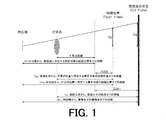
- FIG. 1 is a diagram for explaining the principle of distance measurement used in the authentication apparatus of the present invention.
- FIG. 2 is a diagram for explaining the principle of distance measurement used in the authentication apparatus of the present invention.
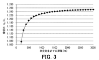
- 3 is an image magnification of the magnification of the first optical image formed by the first optical system shown in FIG. 2 and the magnification of the second optical image formed by the second optical system shown in FIG. It is a graph for demonstrating that ratio changes according to the distance to a measuring object.
- FIG. 4 is a block diagram schematically showing an authentication device according to the first embodiment of the present invention.
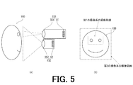
- FIG. 5 is a schematic diagram for illustrating the imaging ranges of the first imaging system and the second imaging system of the authentication apparatus shown in FIG. FIG.
- FIG. 5A is a side view of the subject, the first imaging system, and the second imaging system in order to show the imaging ranges of the first imaging system and the second imaging system of the authentication apparatus shown in FIG.
- FIG. 5B is a schematic view of the subject as seen from the front in order to show the imaging ranges of the first imaging system and the second imaging system of the authentication apparatus shown in FIG.
- FIG. 6 is a block diagram schematically showing a first imaging system and a second imaging system of the authentication apparatus according to the second embodiment of the present invention.
- FIG. 7 is a block diagram schematically showing a first imaging system and a second imaging system of the authentication apparatus according to the third embodiment of the present invention.
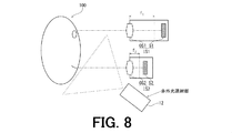
- FIG. 8 is a block diagram schematically showing a first imaging system, a second imaging system, and an infrared light irradiation unit of an authentication apparatus according to the fourth embodiment of the present invention.
- FIG. 9 is a block diagram schematically showing a first imaging system, a second imaging system, and a projector of an authentication apparatus according to the fifth embodiment of the present invention.
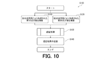
- FIG. 10 is a flowchart showing an authentication method executed by the authentication apparatus of the present invention.
- FIG. 11 is a flowchart showing in more detail the authentication process in the authentication method executed by the authentication apparatus of the present invention.
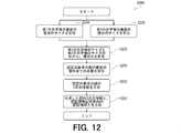
- FIG. 12 is a flowchart showing three-dimensional face authentication in the authentication method executed by the authentication apparatus of the present invention.
- the optical magnification m OD formed by the optical system is the distance (subject distance) a from the front principal point (front principal surface) of the optical system to the measurement object, and the rear principal point (rear principal surface) of the optical system.
- the distance b OD to the image formation position of the optical image and the focal length f of the optical system can be expressed by the following formula (1) from the lens formula.
- the size Y OD of the optical image can be expressed by the following formula (2) from the magnification m OD of the optical image and the actual size sz of the measurement target.
- the size Y OD of the optical image can be expressed by the above equation (2).
- the size Y OD of the optical image can be obtained using the above formula (2).
- the optical system is a fixed focus system that does not have an autofocus function
- the imaging surface of the image sensor such as a sensor is not at the imaging position of the optical image, that is, if defocusing exists
- the image of the image sensor is captured.
- the defocus amount that is, the difference (shift in the optical axis direction) between the imaging position of the optical image and the position of the imaging surface of the image sensor. Amount).
- the distance from the exit pupil of the optical system to the imaging position of the optical image when the measurement target exists at infinity is EP
- the measurement target is an arbitrary distance from the exit pupil of the optical system.
- EP OD is a distance from the exit pupil of the optical system to the imaging surface of the image sensor (Focus Distance)
- EP FD is a distance from the optical system to the imaging position of the optical image when it exists in a.
- the distance from the rear principal point of the optical system to the image formation position of the optical image when the measurement target exists at an arbitrary distance a is b OD
- the imaging surface of the image sensor from the rear principal point of the optical system The distance to is b FD .
- the distance b OD from the rear principal point of the optical system to the imaging position of the optical image when the measurement target exists at an arbitrary distance a can be obtained from the lens formula according to the following formula (3).
- the distance b FD from the rear principal point of the optical system to the imaging surface of the image sensor is a distance a from the front principal point of the optical system to the measurement target when the optical image is best focused on the imaging surface of the image sensor.
- FD the following formula (5) can be obtained from the lens formula.
- the intersection of the optical axis and the exit pupil of the optical system is one of the vertices, and the optical image at the imaging position of the optical image when the measurement target exists at an arbitrary distance a.
- the size Y FD of the optical image on the imaging surface of the image sensor is determined by the actual size sz of the measurement target, the focal length f of the optical system, and the exit pupil of the optical system.
- the optical system when the optical image is best focused on the distance EP from the optical image to the imaging position when the optical image exists at an infinite distance, the distance (object distance) a from the optical system to the measurement object, and the imaging surface of the imaging device Can be expressed as a function of the distance a FD from the measurement object to the measurement object.
- the first imaging system IS1 condenses the light from the measurement target, forms a first optical image, and the first optical image formed by the first optical system OS1.
- the second imaging system IS2 condenses the light from the measurement target, forms a second optical image, and the second optical image formed by the second optical system OS2.
- a second imaging element S2 for imaging As is clear from FIG. 2, the optical axis of the first optical system OS1 of the first image sensor S1 and the optical axis of the second optical system OS2 of the second image sensor S2 are parallel. , Do not match.
- the first optical system OS1 and the second optical system OS2 are fixed-focus optical systems having focal lengths f 1 and f 2 , respectively.
- the position (lens position) of the first optical system OS1 that is, the separation distance between the first optical system OS1 and the first imaging element S1 is an arbitrary distance a.
- the first optical image of the measurement target in FD1 is formed on the imaging surface of the first image sensor S1, that is, the measurement target at an arbitrary distance a FD1 is adjusted to be the best focus.
- the position (lens position) of the second optical system OS2 that is, the separation distance between the second optical system OS2 and the second imaging element S2 is arbitrary.
- the second optical image of the measurement object at the distance a FD2 is formed on the imaging surface of the second image sensor S2, that is, the measurement object at the arbitrary distance a FD2 is adjusted to be the best focus. ing.
- the distance from the exit pupil of the first optical system OS1 to the imaging position of the first optical image when the measurement target exists at infinity is EP 1
- the exit pupil of the second optical system OS2 from the second distance to the imaging position of the optical image when the measurement object is present at infinity is EP 2.
- the first optical system OS1 and the second optical system OS2 are between the front principal point (front principal surface) of the first optical system OS1 and the front principal point (front principal surface) of the second optical system OS2.
- magnification m 1 of the first optical image formed on the imaging surface of the first imaging element S1 by the first optical system OS1 is given by the following equation: (8).
- EP OD1 is the distance from the exit pupil of the first optical system OS1 to the imaging position of the first optical image when the measurement target exists at the distance a
- EP FD1 is the first FD1. This is the distance from the exit pupil of the optical system OS1 to the imaging surface of the first imaging element S1.
- the positional relationship between the distance EP OD1 and the distance EP FD1 is such that when the first imaging system IS1 is configured, the position of the first optical system OS1 is such that the measurement target at an arbitrary distance a FD1 is the best focus. It is determined by adjusting (lens position).
- ⁇ b OD1 is the focal length f 1 and the distance b OD1 from the rear principal point of the first optical system OS1 to the imaging position of the first optical image when the measurement target exists at the distance a.
- ⁇ b FD1 is the difference between the focal length f 1 and the distance b FD1 from the rear principal point of the first optical system OS1 to the imaging surface of the first imaging element S1, and m OD1 is , The magnification of the first optical image at the imaging position of the first optical image when the measurement target exists at the distance a.
- a FD1 is a distance from the front principal point of the first optical system OS1 to the measurement target when the first optical image is best focused on the imaging surface of the first imaging element S1.
- magnification m 2 of the second optical image formed on the imaging surface of the second imaging element S2 by the second optical system OS2 can be expressed by the following formula (10).
- EP OD2 is the distance from the exit pupil of the second optical system OS2 to the imaging position of the second optical image when the measurement target exists at the distance a + D
- EP FD2 is the second FD2 This is the distance from the exit pupil of the optical system OS2 to the imaging surface of the second imaging element S2.
- the positional relationship between the distance EP OD2 and the distance EP FD2 is such that when the second imaging system IS2 is configured, the position of the second optical system OS2 is such that the measurement target at an arbitrary distance a FD2 is the best focus. It is determined by adjusting (lens position).
- ⁇ b OD2 is the focal length f 2 and the distance b OD2 from the rear principal point of the second optical system OS2 to the imaging position of the second optical image when the measurement target exists at the distance a + D.
- ⁇ b FD2 is the difference between the focal length f 2 and the distance b FD2 from the rear principal point of the second optical system OS2 to the imaging surface of the second imaging element S2, and m OD2 is ,
- a FD2 is the second optical image on the imaging surface of the second image sensor S2. Is the distance from the front principal point of the second optical system OS2 to the object to be measured.
- the image magnification ratio MR with the magnification m 2 of the second optical image formed above can be expressed by the following formula (11).
- K is a coefficient, and is based on fixed values f 1 , f 2 , EP 1 , EP 2 , a FD1 , and a FD2 determined by the configurations of the first imaging system IS1 and the second imaging system IS2. It is expressed by the following formula (12).
- the magnification m 1 of the first optical image formed on the imaging surface of the first imaging element S1 by the first optical system OS1 and the second optical system OS2 The image magnification ratio MR with the magnification m2 of the second optical image formed on the imaging surface of the second imaging element S2 depends on the distance a from the measurement target to the front principal point of the first optical system OS1. Change.
- f 1 , f 2 , EP 1 , EP 2 , D and K are fixed values determined by the configurations of the first imaging system IS1 and the second imaging system IS2, image magnification If the ratio MR can be obtained, the distance a from the measurement object to the front principal point of the first optical system OS1 can be calculated.
- the magnification m 1 of the first optical image formed on the imaging surface of the first imaging device S1 by the first optical system OS1 calculated based on the above equation (13)
- the first An example of the relationship between the image magnification ratio MR with the magnification m2 of the second optical image formed on the imaging surface of the second imaging element S2 by the second optical system OS2 and the distance a to the measurement target is as follows. It is shown. As is apparent from FIG. 3, a one-to-one relationship is established between the value of the image magnification ratio MR and the distance a to the measurement target.
- the image magnification ratio MR can be calculated by the following equation (14).
- Y FD1 is the first optical image formed by the first optical system OS1 on the imaging surface of the first imaging element S1
- Y FD2 is the size (image height or image width) of the second optical image formed on the imaging surface of the second imaging element S2 by the second optical system OS2.
- the first optical image size Y FD1 and the second optical image size Y FD2 indicate that the first image sensor S1 and the second image sensor S2 capture the first optical image and the second optical image. Can be calculated from the image of the first optical image (first image) and the image of the second optical image (second image) obtained by the above. Therefore, the size Y FD1 of the first optical image is obtained from the first image and the second image obtained by actually imaging the measurement object using the first imaging system IS1 and the second imaging system IS2. and the second actually measured size Y FD2 of the optical image, based on that, it is possible to obtain a magnification m 1 of the first optical image of Zobaihi MR with magnification m 2 of the second optical image.
- the distance EP 1 from the exit pupil of the system OS1 to the imaging position of the first optical image when the measurement target is at infinity is the measurement target from the exit pupil of the second optical system OS2.
- the image magnification ratio MR is not established as a function of the distance a
- the image magnification ratio MR is a constant.
- the change of the magnification m 1 of the first optical image according to the distance a to the measurement object is the same as the change of the magnification m 2 of the second optical image according to the distance a to the person 100 to be authenticated. Accordingly, it becomes impossible to calculate the distance a from the first optical system OS1 to the measurement object based on the image magnification ratio MR.
- the image magnification ratio MR is the distance. It does not hold as a function of a, and the image magnification ratio MR is a constant. Even in such a special case, it is impossible to calculate the distance a from the first optical system OS1 to the measurement object based on the image magnification ratio MR.
- the first optical system OS1 and the second optical system OS2 are configured and arranged so that at least one of the following three conditions is satisfied, and thereby the distance a to the measurement target a
- the change in the magnification m1 of the first optical image according to the difference from the change in the magnification m2 of the second optical image according to the distance a to the measurement object is different.
- the focal length f 1 of the (first condition) first optical system OS1, the focal length f 2 of the second optical system OS2 are different from each other (f 1 ⁇ f 2)
- (Second Condition) Distance EP 1 from the exit pupil of the first optical system OS1 to the imaging position of the first optical image when the measurement target is at infinity, and the exit of the second optical system OS2
- the distance EP 2 from the pupil to the imaging position of the second optical image when the measurement target is at infinity is different from each other (EP 1 ⁇ EP 2 ).
- a difference D in the depth direction exists between the front principal point of the first optical system OS1 and the front principal point of the second optical system OS2 (D ⁇ 0).
- the image magnification ratio MR is not established as a function of the distance a, and the distance a from the first optical system OS1 to the measurement target is calculated based on the image magnification ratio MR. Is impossible. Therefore, in order to calculate the distance a from the first optical system OS1 to the measurement object based on the image magnification ratio MR, the authentication apparatus of the present invention says that the image magnification ratio MR is established as a function of the distance a. The fourth condition is further satisfied.
- the image magnification ratio MR is calculated from the size Y FD1 of the first optical image and the size Y FD2 of the second optical image measured from the first image and the second image acquired using the authentication apparatus of the present invention. Is calculated, the distance a from the front principal point of the first optical system OS1 to the measurement target can be calculated.
- the authentication apparatus uses the first optical image magnification m 1 and the second optical image size Y FD1 and the second optical image size Y FD2 based on the actually measured first optical image size Y FD1 and second optical image size Y FD2 . by calculating the Zobaihi MR with magnification m 2 of the optical image, and calculates the distance a to the measurement target from the front principal point of the first optical system OS1.
- the measurement objects are a plurality of locations on the face of the person to be authenticated 100 that is the object of authentication of the authentication apparatus of the present invention.
- the distance a to each of a plurality of locations of the face of the person 100 to be authenticated is calculated.
- Three-dimensional information of the face of the person 100 to be authenticated is generated.
- the three-dimensional information of the face of the person 100 to be authenticated generated in this way is used for three-dimensional face authentication.
- FIG. 4 is a block diagram schematically showing an authentication device according to the first embodiment of the present invention.
- FIG. 5 is a schematic diagram for illustrating the imaging ranges of the first imaging system and the second imaging system of the authentication apparatus shown in FIG.
- the authentication device 1 shown in FIG. 4 condenses the light from the authentication target person 100 and the control unit 2 that controls the authentication device 1, and forms a first optical image of the authentication target person 100.
- the first imaging system IS1 having the first imaging element S1 for capturing the first optical image formed by the first optical system OS1 and the first optical system OS1, and the light from the person 100 to be authenticated.
- a second optical system OS2 for illuminating and forming a second optical image of the person 100 to be authenticated, and a second image sensor for imaging the second optical image formed by the second optical system OS2.
- Association information storage unit 3 that stores association information for associating with the distance a to Based on the first optical image and the second optical image
- the distance calculation unit 4 for calculating the distance a to each of the plurality of portions of the face of the person 100 to be authenticated and the distance calculation unit 4 calculate Based on the distance to each of a plurality of portions of the face of the person to be authenticated 100
- a three-dimensional information generation unit 5 for generating three-dimensional information of the face of the person to be authenticated 100, and authentication information necessary for authentication
- An authentication information storage unit 6 that stores information, an authentication unit 7 for executing authentication processing of the person 100 to be authenticated, an operation unit 8 for inputting an operation by a user, and arbitrary information such as a liquid crystal panel
- a display unit 9 for displaying the data
- the authentication apparatus 1 of the present embodiment is required to calculate the distance a to the measurement target (that is, each of a plurality of portions of the face of the authentication target person 100) based on the image magnification ratio MR.
- the focal length f 1 of the first optical system OS1 so that the focal length f 2 of the second optical system OS2 is different (f 1 ⁇ f 2) first condition that is met each other
- the first optical system OS1 and the second optical system OS2 are configured.
- the first optical system OS1 and the second optical system OS2 satisfy the other two conditions (EP 1 ⁇ EP 2 and D ⁇ 0) among the above three conditions. Not configured and arranged.
- the authentication device 1 of the present embodiment is configured to satisfy the fourth condition that the image magnification ratio MR is established as a function of the distance a.
- the magnification m of the first magnification m 1 and a second optical image of the optical image by imaging a subject of authentication 100 by the first imaging system IS1 and the second imaging system IS2 2 is calculated, and the distance a to each of a plurality of portions of the face of the person to be authenticated 100 is calculated using the above equation (15).
- the authentication device 1 according to the present embodiment generates three-dimensional information of the face of the person to be authenticated 100 based on the calculated distance a to each of a plurality of locations of the face of the person to be authenticated 100, and performs three-dimensional face authentication. Run.
- the control unit 2 exchanges various data and various instructions with each component via the data bus 11 and executes control of the authentication device 1.
- the control unit 2 includes a processor for executing arithmetic processing and a memory for storing data, programs, modules, and the like necessary for controlling the authentication device 1, and the processor of the control unit 2 is
- the authentication apparatus 1 is controlled by using data, programs, modules, etc. stored in the memory.
- the processor of the control unit 2 can provide a desired function by using each component of the authentication device 1.
- the processor of the control unit 2 uses the distance calculation unit 4 and based on the first optical image and the second optical image captured by the first imaging system IS1 and the second imaging system IS2. A process for calculating the distance a to each of a plurality of locations on the face of the person to be authenticated 100 can be executed.
- the processor of the control unit 2 is, for example, one or more microprocessors, a microcomputer, a microcontroller, a digital signal processor (DSP), a central processing unit (CPU), a memory control unit (MCU), and an image processing processing unit. (GPU), a state machine, a logic circuit, an application specific integrated circuit (ASIC), or an arithmetic unit that executes arithmetic processing such as signal manipulation based on computer readable instructions such as a combination thereof.
- the processor of the control unit 2 is configured to fetch computer readable instructions (eg, data, programs, modules, etc.) stored in the memory of the control unit 2 and perform signal operations and control.
- the memory of the control unit 2 includes a volatile storage medium (for example, RAM, SRAM, DRAM), a nonvolatile storage medium (for example, ROM, EPROM, EEPROM, flash memory, hard disk, optical disk, CD-ROM, digital versatile disk ( A removable or non-removable computer readable medium comprising a DVD), magnetic cassette, magnetic tape, magnetic disk), or combinations thereof.
- a volatile storage medium for example, RAM, SRAM, DRAM
- a nonvolatile storage medium for example, ROM, EPROM, EEPROM, flash memory, hard disk, optical disk, CD-ROM, digital versatile disk ( A removable or non-removable computer readable medium comprising a DVD), magnetic cassette, magnetic tape, magnetic disk), or combinations thereof.
- Each of the first imaging system IS1 and the second imaging system IS2 is configured and arranged to capture an image of the person 100 to be authenticated.
- the first optical system OS1 of the first imaging system IS1 collects the light from the person 100 to be authenticated, and the first optical image on the imaging surface of the first imaging element S1 of the first imaging system IS1. It has the function to form.
- the second optical system OS2 of the second imaging system IS2 collects the light from the authentication subject 100 and the second optical image on the imaging surface of the second imaging device S2 of the second imaging system IS2. It has a function for forming.
- the first optical system OS1 and the second optical system OS2 are composed of one or more lenses and optical elements such as a diaphragm. Further, as shown in the figure, the optical axis of the first optical system OS1 and the optical axis of the second optical system OS2 are parallel but do not coincide.
- the first optical system OS1 and a second optical system OS2 is a focal length f 1 of the first optical system OS1 and the focal length f 2 of the second optical system OS2 are different from each other ( f 1 ⁇ f 2 ).
- the change according to the distance a to each of the plurality of portions of the face of the person 100 to be authenticated of the magnification m 1 of the first optical image formed by the first optical system OS1 is changed to the second optical system.
- the change is different from the change according to the distance a to each of a plurality of portions of the face of the person 100 to be authenticated, of the magnification m 2 of the second optical image formed by the OS 2.
- the first optical system OS1 and the second optical system OS2 have the focal length f1 of the first optical system OS1 longer than the focal length f2 of the second optical system OS2. (F 1 > f 2 ).
- the configuration of the first optical system OS1 and the configuration and arrangement of the second optical system OS2 in the present embodiment satisfy the above-described first condition (f 1 ⁇ f 2 ).
- the change of the magnification m 1 of the first optical image with respect to the distance a to each of a plurality of locations on the face of the subject 100 and the second optical with respect to the distance a to each of the locations on the face of the subject 100 to be authenticated. and the change in the magnification m 2 of the image, if so different from each other, may be any aspect.
- the first imaging element S1 of the first imaging system IS1 has a function of capturing a first optical image formed by the first optical system OS1 and acquiring a first image.
- the second imaging element S2 of the second imaging system IS2 has a function of capturing a second optical image formed by the second optical system OS2 and acquiring a second image. .
- the first image sensor S1 and the second image sensor S2 are CMOS image sensors or CCD images having color filters such as RGB primary color filters and CMY complementary color filters arranged in an arbitrary pattern such as a Bayer array. It may be a color image sensor such as a sensor, or may be a monochrome image sensor that does not have such a color filter.
- the first optical system OS1 forms a first optical image on the imaging surface of the first imaging device S1, and the first imaging device S1 acquires a color or monochrome first image signal.
- the acquired first image is sent to the control unit 2, the distance calculation unit 4, and the authentication unit 7 via the data bus 11.
- the second optical system OS2 forms a second optical image on the imaging surface of the second imaging element S2, and the second imaging element S2 acquires a color or monochrome second image.
- the acquired second image is sent to the control unit 2, the distance calculation unit 4, and the authentication unit 7 via the data bus 11.
- the first image and the second image sent to the distance calculation unit 4 are used to calculate the distance a to each of a plurality of locations on the face of the person 100 to be authenticated.
- the first image and the second image sent to the authentication unit 7 are used to perform two-dimensional face authentication and / or iris authentication of the person 100 to be authenticated.
- the first image and the second image sent to the control unit 2 are used for image display by the display unit 9 and image communication by the communication unit 10.
- first imaging system IS1 and the second imaging system IS2 are configured in separate housings, but the present invention is not limited to this.
- a mode in which the first imaging system IS1 and the second imaging system IS2 are configured in the same casing is also within the scope of the present invention.
- Association information storage unit 3 and the magnification m 1 of the first optical image and Zobaihi MR (m 2 / m 1) and magnification m 2 of the second optical image, the front of the first optical system OS1 It is an arbitrary non-volatile recording medium (for example, a hard disk or a flash memory) for storing association information that associates a distance (subject distance) a from the principal point to each of a plurality of locations on the face of the person 100 to be authenticated. .
- a non-volatile recording medium for example, a hard disk or a flash memory
- Association information stored in the association information storage unit 3 from Zobaihi MR (m 2 / m 1) between the magnification m 1 of the first optical image and magnification m 2 of the second optical image, This is information for calculating the distance a to each of a plurality of portions of the face of the person 100 to be authenticated.
- the associating information stored in the associating information storage unit 3 is based on the image magnification ratio MR, and calculates the distance a to each of a plurality of locations on the face of the person 100 to be authenticated.
- Formula (15) (or General Formula (13)) and the above-described fixed value (the above Formula (15) determined by the configuration and arrangement of the first optical system OS1 and the second optical system OS2 in the Formula (15)) ) are fixed values f 1 , f 2 , EP, and K).
- the association information stored in the association information storage unit 3 is a lookup that uniquely associates the image magnification ratio MR with the distances a to a plurality of portions of the face of the person 100 to be authenticated. It may be a table. By referring to such association information stored in the association information storage unit 3, the distance a to each of a plurality of portions of the face of the person to be authenticated 100 is calculated based on the image magnification ratio MR. Is possible.
- the distance calculation unit 4 uses each of a plurality of portions of the face of the person to be authenticated 100 based on the first optical image and the second optical image captured by the first imaging system IS1 and the second imaging system IS2. Has a function of calculating the distance a. More specifically, the distance calculation unit 4, and the magnification m 1 of the first optical image based on Zobaihi MR with magnification m 2 of the second optical image, the object's 100 face a plurality of It has a function of calculating the distance a to each of the locations.
- the distance calculation unit 4 receives the first image from the first imaging element S1 of the first imaging system IS1, and further receives the second image from the second imaging element S2 of the second imaging system IS2. To do.
- the distance calculation unit 4 performs a filtering process such as Canny on the first image and the second image, and a plurality of edge portions of the first optical image and the second image in the first image. A plurality of edge portions of the second optical image in the image are extracted.
- the distance calculation unit 4 calculates the size (image width or image height) Y FD1 of a plurality of portions of the first optical image based on the plurality of edge portions of the extracted first optical image, and further extracts Based on the edge portion of the second optical image, the size (image width or image height) Y FD2 of a plurality of locations of the second optical image is calculated.
- the distance calculation unit 4 changes the combination of a plurality of edge portions used to calculate the sizes Y FD1 and Y FD2 , thereby changing the sizes Y FD1 of the plurality of locations of the first optical image and the second optical image , Y FD2 is acquired.
- the distance calculation unit 4 selects an edge part adjacent in the height direction from among the plurality of extracted edge parts, and measures the distance between them, thereby calculating the image height of an arbitrary part in the optical image. Can be acquired.
- the distance calculation unit 4 selects an edge part adjacent in the width direction from among the plurality of extracted edge parts, and measures the distance between them, thereby calculating the image width of an arbitrary portion in the optical image. Can be acquired.
- the selection of the plurality of extracted edge portions by the distance calculation unit 4 is executed so that all or some combinations of the edge portions located in the area corresponding to the face of the person to be authenticated 100 are covered.
- the distance calculation unit 4 may select a plurality of extracted edge portions so as to cover all or some combinations of the extracted edge portions. In this way, the distance calculation unit 4 acquires the size Y FD1 of each of the plurality of locations of the first optical image and the size Y FD2 of each of the plurality of locations of the second optical image.
- the distance calculation unit 4 refers to the association information stored in the association information storage unit 3 and based on the image magnification ratio MR, the authentication target person 100 The distance a to each of a plurality of locations on the face is calculated (specified).
- the three-dimensional information generation unit 5 has a function of generating the three-dimensional information of the face of the authentication target person 100 based on the distance a to each of the plurality of portions of the face of the authentication target person 100 calculated by the distance calculation part 4. Have.
- the three-dimensional information generation unit 5 receives the distances a from the distance calculation unit 4 to each of the plurality of portions of the face of the authentication target person 100, the three-dimensional information generation unit 5 Mesh) and texture are generated, and the face of the person 100 to be authenticated is three-dimensionally modeled.
- the dimension information generation unit 5 performs interpolation of the height (depth) information of the authentication target person 100 using any interpolation technique such as bilinear interpolation, bicubic interpolation, nearest neighbor interpolation, and the like. 3D model.
- the 3D information generation unit 5 extracts the 3D feature of the face of the authentication target person 100 as the 3D information of the face of the authentication target person 100 from the 3D model of the face of the authentication target person 100.
- the 3D information of the face extracted from the 3D model of the face includes, for example, the height of the nose, the shape of the nose (the direction and shape of the nose tip, the shape and height of the back of the nose, the shape of the nose wing), The depth of the depression and the distance in the depth direction between each part of the face (eye, nose, mouth, ear, eyebrow, etc.) can be mentioned.
- Such 3D information of the face of the person 100 to be authenticated is used in 3D face authentication executed by the authentication unit 7 described later.
- the authentication information storage unit 6 is an arbitrary nonvolatile recording medium (for example, a hard disk or a flash memory) that stores authentication information necessary for executing authentication of the person 100 to be authenticated.
- An administrator or the like of the authentication device 1 of the present invention is permitted to authenticate in advance by imaging a person who has been authenticated using the authentication device 1 of the present invention or an imaging device having an equivalent function.
- the three-dimensional information of the person, the first image, and the second image are acquired, and these are registered in the authentication information storage unit 6 as authentication information.
- the acquired three-dimensional information, the first image, and / or the second image of the authentication target person 100 is stored in the authentication information storage part 6 when the authentication unit 7 described later performs an authentication process on the authentication target person 100.
- 3D face authentication, 2D face authentication, and / or iris authentication are executed in comparison with the stored authentication information.
- the authentication information storage unit 6 is provided inside the authentication device 1, but the present invention is not limited to this.
- the authentication information storage unit 6 is an external server or an external storage device connected to the authentication apparatus 1 via various wired or wireless networks such as the Internet, a local area network (LAN), and a wide area network (WAN). Also good.
- the authentication information storage unit 6 is an external server or an external storage device, one or more authentication information storage units 6 may be shared among a plurality of authentication devices 1.
- the authentication device 1 communicates with the authentication information storage unit 6 provided outside by using the communication unit 10 every time the authentication of the authentication target person 100 is executed, and authenticates the authentication target person 100. Run.
- the authentication unit 7 is configured to be able to execute the three-dimensional face authentication of the authentication target person 100 using the three-dimensional information of the face of the authentication target person 100 calculated by the three-dimensional information generation unit 5. More specifically, the authentication unit 7 includes the 3D information of the face of the person to be authenticated 100 calculated by the 3D information generation unit 5 and the face included in the authentication information registered in advance in the authentication information storage unit 6. The three-dimensional face authentication of the person 100 to be authenticated is executed by comparing the three-dimensional information.
- any one of a plurality of elements such as the height of the nose and the depth of the eye dent included in the three-dimensional information of the face of the person 100 to be authenticated is registered in the authentication information storage unit 6 in advance. If the face of the authentication information matches the corresponding element of the three-dimensional information, it may be determined that the three-dimensional face authentication is successful, or all of the plurality of elements are registered in the authentication information storage unit 6 in advance. It may be determined that the three-dimensional face authentication has succeeded when the corresponding element of the three-dimensional information of the authentication information face matches.
- the authentication unit 7 uses the first image and the second image received from the first imaging system IS1 and the second imaging system IS2 to authenticate the person 100.
- the iris authentication and the two-dimensional face authentication can be executed. Specifically, the authentication unit 7 extracts a face two-dimensional feature value and eye iris information from the first image and / or the second image, and extracts the extracted face two-dimensional feature value and eye iris. Using the information, the authentication target person 100 can perform iris authentication and two-dimensional face authentication.
- the method by which the authentication unit 7 extracts the two-dimensional feature amount of the face and the iris information of the eye from the first image and / or the second image is not particularly limited, and using various algorithms known in the field, It is possible to extract a two-dimensional feature amount of the face and iris information of the eyes.
- the authentication unit 7 includes a two-dimensional feature amount of the face of the person to be authenticated 100 extracted from the first image and / or the second image received from the first imaging system IS1 and the second imaging system IS2, and authentication.
- the two-dimensional face value of the person 100 to be authenticated is compared with the two-dimensional feature amount of the face extracted from the first image and / or the second image included in the authentication information registered in advance in the information storage unit 6. Configured to allow authentication.
- the two-dimensional face authentication method executed by the authentication unit 7 is not particularly limited.
- the authentication unit 7 can perform the eigenface method, linear discriminant analysis, graph matching method, frequency analysis method, neural network method, Viola-Jones method.
- the two-dimensional face authentication of the person 100 to be authenticated can be executed using any two-dimensional face authentication algorithm such as.
- the authentication unit 7 also includes iris information of the eye of the person to be authenticated 100 extracted from the first image and / or the second image received from the first imaging system IS1 and the second imaging system IS2, and authentication.
- the iris authentication of the person 100 to be authenticated can be executed by comparing the iris information of the eye extracted from the first image and / or the second image included in the authentication information registered in advance in the information storage unit 6 It is configured.
- the method of iris authentication executed by the authentication unit 7 is not particularly limited.
- the authentication unit 7 may execute the iris authentication of the person 100 to be authenticated using an arbitrary iris authentication algorithm such as the Dangman algorithm. it can.
- the first optical system OS1 and the second optical system OS2 have the focal length f1 of the first optical system OS1 and the focal length f of the second optical system OS2. It is configured to be longer than 2 (f 1 > f 2 ). Therefore, the authentication device 1 of the present embodiment can easily acquire two images (first image and second image) having different angles of view at the same time.
- the angle of view of the first image acquired by the first imaging system IS1 is narrower than the angle of view of the second image acquired by the second imaging system IS2.
- the magnification of the first image acquired by the first imaging system IS1 is higher than the magnification of the second image acquired by the second imaging system IS2.
- iris authentication an iris, which is a fine structure of the eye, is used. Therefore, in the image used for iris authentication, it is preferable that the eye of the person 100 to be authenticated is enlarged and photographed greatly.
- the first image and the second image are compared, the first image has a narrow angle of view and a high magnification. Therefore, the iris authentication is executed using the first image having a narrow angle of view and a high magnification.
- two-dimensional face authentication that requires a wider range of images but does not require information on fine structure compared to iris authentication uses a second image with a wide angle of view and low magnification, Executed.
- the first imaging system IS1 has an imaging range of the first imaging system IS1 (FIGS. 5A and 5B). (Range indicated by a dotted line in the figure) is configured and arranged so that only the peripheral area of the eye of the authentication target person 100 including the eye of the authentication target person 100 is included.
- the second imaging system IS2 is within the imaging range of the second imaging system IS2 (the range indicated by the alternate long and short dash line in FIGS. 5A and 5B). It is configured and arranged so that the entire face of the person to be authenticated 100 is included.
- the authentication unit 7 of the present embodiment performs iris authentication of the person 100 to be authenticated using the first image acquired by the first imaging system IS1, and further, the second imaging system IS2 acquires the first image acquisition system IS2.
- the two-dimensional face authentication of the person 100 to be authenticated is executed using the two images. With such a configuration, the accuracy of iris authentication and two-dimensional face authentication of the person 100 to be authenticated can be improved.
- the authentication unit 7 is configured to be able to execute three types of authentication, that is, 3D face authentication, 2D face authentication, and iris authentication.
- the authentication unit 7 executes at least one of these three authentications according to a security level (for example, “high”, “medium”, and “low”) set in advance for the authentication device 1. be able to.
- the security level of the authentication device 1 may be set manually by the administrator of the authentication device 1 or the like using the operation unit 8, or the authentication device 1 is portable by the administrator or the like via the communication unit 10.
- a security level may be set based on a security level setting command received from an external device such as a telephone, a smartphone, a laptop computer, or a laptop computer.
- the authentication unit 7 performs both the three-dimensional face authentication and the iris authentication of the person 100 to be authenticated.
- the processing time required for the authentication becomes long.
- the authentication unit 7 determines that the authentication of the authentication target person 100 is successful only when both the three-dimensional face authentication and the iris authentication are successful.
- the authentication unit 7 determines that there is a high possibility that impersonation with a photograph has been executed in addition to the authentication of the authentication target person 100 having failed. To do.
- the authentication unit 7 performs both the two-dimensional face authentication and the iris authentication of the person 100 to be authenticated.
- 2D face authentication requires less processing time than 3D face authentication, which requires processing of a 3D model of a face, and therefore processing required for authentication is compared to when the security level is set to “high”. Time can be shortened.
- a double check of two-dimensional face authentication and iris authentication can be executed, and the accuracy of authentication of the person 100 to be authenticated can be improved. In this case, the authentication unit 7 determines that the authentication target person 100 has been successfully authenticated only when both the two-dimensional face authentication and the iris authentication are successful.
- the authentication unit 7 executes the two-dimensional face authentication or iris authentication of the person 100 to be authenticated. In this case, the authentication unit 7 determines that the authentication of the authentication target person 100 is successful when either one of the two-dimensional face authentication and the iris authentication is successful. If either one of the two-dimensional face authentication and the iris authentication is successful, it is determined that the authentication target person 100 has been successfully authenticated. Therefore, the processing time required for authentication of the authentication target person 100 can be further shortened.
- the execution order of the two-dimensional face authentication and the iris authentication is not particularly limited. For example, the authentication unit 7 first executes the two-dimensional face authentication, and a part of the face of the person 100 to be authenticated is hidden by a mask or the like. It may be configured to perform iris authentication when the two-dimensional face authentication fails.
- the authentication result (judgment result) of the person 100 to be authenticated by the authentication unit 7 is sent to the control unit 2 via the data bus 11.
- the control unit 2 transmits the received authentication result to an external device (for example, a door unlocking device, a terminal that provides an arbitrary application, etc.) via the communication unit 10.
- the external device can execute processing according to the received authentication result. For example, when the external device receives the result that the authentication target person 100 has been successfully authenticated, the external device unlocks a physical lock or software such as a door lock, or activates an arbitrary application.
- a physical lock such as a door lock or a software lock is maintained, or activation of an arbitrary application is not permitted. Further, for example, when the external device receives a result that the impersonation by the photograph has been executed, the external device notifies the external device, the administrator of the authentication apparatus 1 or the like with a security warning message.
- the authentication unit 7 selects an authentication process to be executed in accordance with a security level set in advance, so that the authentication device 1 of the present invention can be used for various security applications.
- the operation unit 8 is used by a user or an administrator of the authentication device 1 to execute an operation.
- the operation unit 8 is not particularly limited as long as the user of the authentication device 1 can execute the operation.
- a mouse, a keyboard, a numeric keypad, a button, a dial, a lever, a touch panel, or the like can be used as the operation unit 8.
- the operation unit 8 transmits a signal corresponding to an operation by the user of the authentication device 1 to the processor of the control unit 2.
- the administrator or the like of the authentication device 1 can set the security level of the authentication device 1 using the operation unit 8.
- the communication unit 10 has a function of inputting data to the authentication device 1 or outputting data from the authentication device 1 to an external device by wired communication or wireless communication.
- the communication unit 10 may be configured to be connectable to a network such as the Internet.
- the authentication apparatus 1 can communicate with an external device such as a web server or a data server provided outside by using the communication unit 10.
- the first optical system OS1 and the second optical system OS2 have the focal length f1 of the first optical system OS1 and the focal length f of the second optical system OS2. 2 is different from each other (f 1 ⁇ f 2 ), whereby the magnification m 1 of the first optical image with respect to the distance a to each of a plurality of portions of the face of the person to be authenticated 100 is set.
- the change and the change of the magnification m 2 of the second optical image with respect to the distance a to each of the plurality of locations on the face of the person to be authenticated 100 are different from each other.
- the authentication apparatus 1 of this embodiment based on Zobaihi MR (m 2 / m 1) between the magnification m 1 of the first optical image and magnification m 2 of the second optical image, the object's The distance a to each of a plurality of locations of 100 faces can be calculated uniquely. Furthermore, the authentication device 1 according to the present embodiment generates the three-dimensional information of the face of the authentication target person 100 based on the calculated distances a to the plurality of portions of the face of the authentication target person 100, and the authentication target person 100 three-dimensional face authentication can be performed.
- FIG. 6 is a block diagram schematically showing a first imaging system and a second imaging system of the authentication apparatus according to the second embodiment of the present invention.
- the authentication device 1 according to the second embodiment will be described focusing on the differences from the authentication device 1 according to the first embodiment, and description of similar matters will be omitted.
- the authentication device 1 of the present embodiment is the same as the authentication device 1 of the first embodiment, except that the configurations of the first optical system OS1 and the second optical system OS2 are changed.
- the authentication apparatus 1 of the present embodiment is based on the image magnification ratio MR, and the above three conditions required for calculating the distance a to the measurement target (each of a plurality of locations on the face of the authentication target person 100). of, from the exit pupil of the first optical system OS1, the distance EP 1 to the imaging position of the first optical image when the measurement object is at infinity, the exit pupil of the second optical system OS2,
- the first optical system is such that the second condition that the distance EP 2 to the imaging position of the second optical image when the measurement target is at infinity is different (EP 1 ⁇ EP 2 ) is satisfied.
- the OS1 and the second optical system OS2 are configured.
- the first optical system OS1 and the second optical system OS2 satisfy the other two conditions (f 1 ⁇ f 2 and D ⁇ 0) among the above three conditions. Not configured and arranged. Furthermore, the authentication device 1 of the present embodiment is configured to satisfy the fourth condition that the image magnification ratio MR is established as a function of the distance a.
- the first measurement when the measurement target (each of the plurality of portions of the face of the authentication target person 100) is at infinity from the exit pupil of the first optical system OS1.
- the distance EP 1 to the imaging position of the optical image from the exit pupil of the second optical system OS2, and the distance EP 2 to the imaging position of the second optical image when the measurement object is at infinity is,
- the first optical system OS1 and the second optical system OS2 are configured so as to be different from each other (EP 1 ⁇ EP 2 ), whereby the distance a to each of a plurality of locations on the face of the person 100 to be authenticated and the change in the magnification m 1 of the first optical image, a second magnification m 2 of the optical image changes relative to the distance a to each of the plurality of locations of the object's face 100 and, taken different from each other Yes.
- the authentication apparatus 1 of this embodiment based on Zobaihi MR (m 2 / m 1) between the magnification m 1 of the first optical image and magnification m 2 of the second optical image, the object's The distance a to each of a plurality of locations of 100 faces can be calculated uniquely. Furthermore, the authentication device 1 according to the present embodiment generates the three-dimensional information of the face of the authentication target person 100 based on the calculated distances a to the plurality of portions of the face of the authentication target person 100, and the authentication target person 100 three-dimensional face authentication can be performed.
- the same effects as those of the first embodiment described above can be exhibited.
- the configuration and arrangement of the first optical system OS1 and the second optical system OS2 in this embodiment satisfy the above-described second condition (EP 1 ⁇ EP 2 ).
- any mode may be used.
- the iris authentication of the person to be authenticated 100 may be executed using either the first image acquired by the second imaging system IS2 or the second image acquired by the second imaging system IS2.
- FIG. 7 is a block diagram schematically showing a first imaging system and a second imaging system of the authentication apparatus according to the third embodiment of the present invention.
- the authentication device 1 according to the third embodiment will be described focusing on the differences from the authentication device 1 according to the first embodiment, and description of similar matters will be omitted.
- the authentication device 1 of the present embodiment is the same as the authentication device 1 of the first embodiment, except that the configuration and arrangement of the first optical system OS1 and the second optical system OS2 are changed.
- the authentication apparatus 1 satisfies the above three conditions required for calculating the distance a to the measurement target (each of the plurality of portions of the face of the authentication target person 100) based on the image magnification ratio MR.
- D digital ⁇ 0
- the first optical system OS1 and the second optical system OS2 are configured and arranged so that the condition is satisfied.
- the first optical system OS1 and the second optical system OS2 satisfy the other two conditions (f 1 ⁇ f 2 and EP 1 ⁇ EP 2 ) among the above three conditions. Is not configured to.
- the authentication device 1 of the present embodiment is configured to satisfy the fourth condition that the image magnification ratio MR is established as a function of the distance a.
- the first optical system OS1 and the second optical system OS2 are the front principal point of the first optical system OS1 and the front principal point of the second optical system OS2.
- D depth direction
- D ⁇ 0 the distance a to each of a plurality of locations on the face of the person 100 to be authenticated a first change in the magnification m 1 of the optical image of the change in the magnification m 2 of the second optical image with respect to the distance a to each of the plurality of locations of the object's face 100 for is made different from each other ing.
- the authentication apparatus 1 of this embodiment based on Zobaihi MR (m 2 / m 1) between the magnification m 1 of the first optical image and magnification m 2 of the second optical image, the object's The distance a to each of a plurality of locations of 100 faces can be calculated uniquely. Furthermore, the authentication device 1 according to the present embodiment generates the three-dimensional information of the face of the authentication target person 100 based on the calculated distances a to the plurality of portions of the face of the authentication target person 100, and the authentication target person 100 three-dimensional face authentication can be performed.
- the configuration of the first optical system OS1 and the configuration and arrangement of the second optical system OS2 in the present embodiment satisfy the above-described third condition (D ⁇ 0).
- any mode may be used.
- the iris authentication of the person to be authenticated 100 may be executed using either the first image acquired by the second imaging system IS2 or the second image acquired by the second imaging system IS2.
- FIG. 8 is a block diagram schematically showing a first imaging system, a second imaging system, and an infrared light irradiation unit of an authentication apparatus according to the fourth embodiment of the present invention.
- the authentication device 1 according to the present embodiment further includes an infrared light irradiation unit 12 that irradiates the authentication target person 100 with infrared light, and the first imaging element S1 and the second imaging. Except for the point that at least one of the elements S2 is configured to be able to image infrared light, it is the same as the authentication apparatus of the first embodiment.
- the infrared light irradiation unit 12 is connected to the data bus 11 of the authentication device 1 and has a function of irradiating the authentication target person 100 with infrared light according to control from the processor of the control unit 2 of the authentication device 1. Have.
- the infrared light irradiation unit 12 is not particularly limited as long as it can irradiate the authentication target person 100 with infrared light according to the control from the processor of the control unit 2 of the authentication device 1.
- An LED can be used as the infrared light irradiation unit 12.
- At least one of the first imaging element S1 of the first imaging system IS1 and the second imaging element S2 of the second imaging system IS2 is configured to be able to image infrared light.
- the infrared light irradiation unit 12 is authenticated by the authentication target person 100 according to control from the processor of the control unit 2. Irradiate with infrared light. Since at least one of the first imaging device S1 and the second imaging device S2 of the second imaging system IS2 is configured to be capable of imaging infrared light, the first imaging system IS1 and the second imaging system. IS2 can acquire an infrared image of the person 100 to be authenticated even in a dark place.
- the present embodiment at least among the first imaging element S1 of the first imaging system IS1 and the second imaging element S2 of the second imaging system IS2, it is used for at least the iris authentication of the person 100 to be authenticated.
- the first image pickup device S1 of the first image pickup system IS1 is configured to be capable of picking up infrared light (in the case of the first embodiment and the present embodiment). With such a configuration, it is possible to increase the accuracy of the iris authentication of the authentication target person 100 and reduce the burden on the authentication target person 100 during authentication.
- both the first image sensor S1 and the second image sensor S2 are configured to be able to image infrared light is also within the scope of the present invention.
- an infrared image of the face of the person to be authenticated 100 can be acquired even in a dark place, and the above-described authentication target The three-dimensional face authentication and the two-dimensional face authentication of the person 100 can be executed.
- FIG. 9 is a block diagram schematically showing a first imaging system, a second imaging system, and a projector of an authentication apparatus according to the fifth embodiment of the present invention.
- the authentication device 1 of the present embodiment is the same as the authentication device of the first embodiment, except that the authentication device 1 further includes a projector 13 that irradiates the authentication target person 100 with a predetermined pattern.
- the projector 13 is connected to the data bus 11 of the authentication device 1, and in response to control from the processor of the control unit 2 of the authentication device 1, a predetermined pattern (for example, vertical stripe pattern, horizontal stripe pattern, Grid pattern, dot pattern).
- the projector 13 is not particularly limited as long as it can project a predetermined pattern to the person 100 to be authenticated in accordance with control from the processor of the control unit 2 of the authentication device 1.
- a projector such as a CRT projector or a liquid crystal projector can be used. It can be used as the projector 13.
- the projector 13 is predetermined for the authentication target person 100 according to control from the processor of the control unit 2. Project the pattern. Therefore, the first imaging system IS1 and the second imaging system IS2 image the authentication target person 100 in a state where a predetermined pattern is projected.
- the predetermined pattern irradiated to the authentication target person 100 can be used as an edge part used by the distance calculation unit 4 to calculate the distance a to each of a plurality of portions of the face of the authentication target person 100. Since there exists, the measurement location of the distance of the authentication subject person 100 can be increased. Therefore, even if there is no clear edge portion at an arbitrary location of the person to be authenticated 100, the distance a to that location can be calculated. Further, since the number of measurement points of the distance of the authentication target person 100 increases, the accuracy of the three-dimensional modeling of the face of the authentication target person 100 is improved, and as a result, the accuracy of the three-dimensional face authentication of the authentication target person 100 is improved. Can do.
- the authentication device 1 of the present invention does not use translational parallax between a plurality of images, and the magnification m 1 of the first optical image and the second optical image. Based on the image magnification ratio MR (m 2 / m 1 ) with the magnification m 2 , the distance a to each of a plurality of locations on the face of the person to be authenticated 100 can be uniquely calculated.
- the authentication apparatus 1 according to the present invention generates three-dimensional information of the face of the authentication target person 100 based on the calculated distances a to the plurality of portions of the face of the authentication target person 100, and Dimensional face authentication can be performed.
- the authentication apparatus 1 of the present invention does not require a large translational parallax, and therefore the first optical system OS1 and the first optical system OS1. Even if the two optical systems OS2 are arranged close to each other, the distance a to each of a plurality of locations on the face of the person 100 to be authenticated can be accurately calculated. Thereby, compared with the conventional authentication apparatus of a stereo camera system, size reduction of the authentication apparatus 1 is realizable.
- the authentication target person 100 is very different from the authentication apparatus 1. Even in the case of a close position, it is possible to accurately measure the distance a to each of a plurality of locations on the face of the person 100 to be authenticated. Further, according to the present invention, it is not necessary to design the authentication device 1 in consideration of translational parallax, so that the degree of freedom in designing the authentication device 1 can be increased.
- the two optical systems, the first optical system OS1 and the second optical system OS2 are used, but the number of optical systems used is not limited to this.
- an aspect in which an additional optical system is further provided in addition to the first optical system OS1 and the second optical system OS2 is also within the scope of the present invention.
- the additional optical system has a change in the magnification of the optical image formed by the additional optical system with respect to the distance a to each of the plurality of portions of the face of the person 100 to be authenticated.
- the change with respect to the distance a to each of a plurality of portions of the face of the authentication target person 100 having the magnification m 1 and the distance a to each of the plurality of portions of the face of the authentication target person 100 having the magnification m 2 of the second optical image It is constructed and arranged differently from changes.
- the above-described three conditions required for calculating the distance a to the measurement target (each of the plurality of portions of the face of the person to be authenticated 100) based on the image magnification ratio MR.
- the first optical system OS1 and the second optical system OS2 are configured and arranged so as to satisfy any one of them, but the first optical system OS1 is satisfied so that at least one of the above three conditions is satisfied.
- the present invention is not limited to this as long as the system OS1 and the second optical system OS2 are configured and arranged.
- an aspect in which the first optical system OS1 and the second optical system OS2 are configured and arranged so that all or any combination of the above three conditions is satisfied is also within the scope of the present invention. .
- FIG. 10 is a flowchart showing an authentication method executed by the authentication apparatus of the present invention.
- FIG. 11 is a flowchart showing in more detail the authentication process in the authentication method executed by the authentication apparatus of the present invention.
- FIG. 12 is a flowchart showing three-dimensional face authentication in the authentication method executed by the authentication apparatus of the present invention.
- the authentication method described in detail below can be executed using the authentication device 1 according to the first to fifth embodiments of the present invention described above and any device having the same function as the authentication device 1.
- the description will be made assuming that the authentication apparatus 1 is executed according to the first embodiment.
- the authentication method S100 illustrated in FIG. 10 is started when the authentication target person 100 uses the operation unit 8 to execute an operation for executing authentication of the authentication target person 100.
- step S110 a first optical image formed by the first optical system OS1 is captured by the first imaging element S1 of the first imaging system IS1, and a first image is acquired.
- the first image is sent to the control unit 2, the distance calculation unit 4, and the authentication unit 7 via the data bus 11.
- step S120 the second optical image formed by the second optical system OS2 is captured by the second imaging element S2 of the second imaging system IS2, and a second image is acquired.
- the second image is sent to the control unit 2, the distance calculation unit 4, and the authentication unit 7 via the data bus 11.
- process S110 and process S120 may be performed simultaneously, and may be performed separately.
- step S130 the authentication target person 100 is authenticated.
- FIG. 11 shows the authentication process of the person to be authenticated 100 executed in step S130 in more detail.
- step S131 the authentication unit 7 checks the security level of the authentication device 1 set in advance. If it is determined in step S131 that the security level of the authentication device 1 is set to “high”, the authentication process proceeds to step S132.
- step S132 three-dimensional face authentication and iris authentication of the person to be authenticated 100 are executed.
- the iris authentication of the person 100 to be authenticated in step S132 is performed by the authentication unit 7 using the first image or the second image (in the first embodiment, the first image with a narrow angle and a high magnification). Is done.
- step S132 the three-dimensional face authentication of the person 100 to be authenticated is executed.
- FIG. 12 shows the three-dimensional face authentication S200 of the person to be authenticated 100 executed in step S132.
- the three-dimensional face authentication S200 of the person 100 to be authenticated will be described in detail.
- the distance calculation unit 4 calculates the size (image height or image width) Y FD1 of each of the plurality of portions of the first optical image from the first image.
- the distance calculation unit 4 calculates the size (image height or image width) Y FD2 of each of the plurality of portions of the second optical image from the second image.
- process S210 and process S220 may be performed simultaneously, and may be performed separately.
- Step S210 and Step S220 when both the size Y FD1 of the plurality of locations of the first optical image and the size Y FD2 of the plurality of locations of the second optical image are calculated, the process proceeds to Step S230.
- the distance calculation unit 4 refers to the association information stored in the association information storage unit 3 and, based on the calculated image magnification ratio MR, a plurality of faces of the person to be authenticated 100. Calculate (specify) the distance a to each of the locations.
- the process proceeds to step S250.
- step S250 the three-dimensional information generation unit 5 receives the distance a to each of the plurality of locations on the face of the person to be authenticated 100 calculated by the distance calculation unit 4. Thereafter, the three-dimensional information generation unit 5 generates the three-dimensional information of the face of the authentication target person 100 based on the distance a to each of the plurality of portions of the face of the authentication target person 100.
- step S260 the authentication unit 7 is included in the three-dimensional information of the face of the person 100 to be authenticated calculated by the three-dimensional information generation unit 5 and the authentication information registered in advance in the authentication information storage unit 6. By comparing the three-dimensional information of the face, the three-dimensional face authentication of the person 100 to be authenticated is executed.
- any one of a plurality of elements such as the height of the nose and the depth of the eye dent included in the three-dimensional information of the face of the person 100 to be authenticated is registered in the authentication information storage unit 6 in advance. If it matches with the corresponding element of the face three-dimensional information of the authentication information, it is judged that the three-dimensional face authentication is successful, or all of the plurality of elements are registered in the authentication information storage unit 6 in advance. If all the elements of the three-dimensional information of the face match, it is determined that the three-dimensional face authentication is successful.
- Such a three-dimensional face authentication S200 of the person 100 to be authenticated is executed in step S132.
- the authentication unit 7 determines that the authentication of the authentication target person 100 is successful only when both the iris authentication and the three-dimensional face authentication S200 are successful.
- the authentication unit 7 determines that the impersonation by the photograph has been executed in addition to the authentication of the authentication target person 100 having failed.
- the authentication unit 7 transmits a determination regarding the authentication of the person 100 to be authenticated as described above to the control unit 2, and the authentication process in step S130 ends.
- step S131 if it is determined in step S131 that the security level of the authentication device 1 is set to “medium”, the authentication process proceeds to step S133.
- step S133 the authentication unit 7 performs both the two-dimensional face authentication and the iris authentication of the person 100 to be authenticated using the first image and / or the second image.
- step S133 the authentication unit 7 determines that the authentication target person 100 has been successfully authenticated only when both the iris authentication and the two-dimensional face authentication are successful. Thereafter, the authentication unit 7 transmits a determination about the authentication of the person 100 to be authenticated to the control unit 2, and the authentication process in step S130 is completed.
- step S134 the authentication unit 7 performs two-dimensional face authentication or iris authentication of the person 100 to be authenticated using the first image and / or the second image.
- step S134 the authentication unit 7 determines that the authentication target person 100 has been successfully authenticated when at least one of the iris authentication and the two-dimensional face authentication is successful. Thereafter, the authentication unit 7 transmits a determination about the authentication of the person 100 to be authenticated to the control unit 2, and the authentication process in step S130 is completed.
- step S ⁇ b> 140 the control unit 2 receives a determination (authentication result) about authentication of the person 100 to be authenticated from the authentication unit 7.
- the control unit 2 transmits the received authentication result to an arbitrary external device via the communication unit 10, and the authentication method S100 ends. Thereby, an arbitrary external device can execute processing according to the authentication result.
- each component of the present invention can be replaced with any component that can exhibit the same function, or any component of the present invention can be added to each component of the present invention.
- an authentication device having a modified configuration is also within the scope of the present invention.
- the aspect which combined arbitrarily the authentication apparatus of 1st Embodiment to 5th Embodiment is also within the scope of the present invention.
- FIGS. 4 to 9 are merely examples for explanation, and the present invention is not necessarily limited thereto. It is within the scope of the present invention that any component is added or combined, or any component is deleted, without departing from the principle and intention of the present invention.
- Each component of the authentication device may be realized by hardware, may be realized by software, or may be realized by a combination thereof.
- the number and types of steps of the authentication method S100 shown in FIGS. 10 to 12 are merely examples for explanation, and the present invention is not necessarily limited thereto. It is within the scope of the present invention that any step can be added or combined for any purpose or any step can be deleted without departing from the principle and intention of the present invention.
- the authentication apparatus of the present invention uses at least two optical systems having different optical image magnification changes according to the distance to each of a plurality of locations on the face of the person to be authenticated, and is formed by each of the two optical systems. Based on the image magnification ratio (magnification ratio) of the two optical images, the distance to each of a plurality of locations on the face of the person to be authenticated can be measured. Furthermore, the authentication apparatus of the present invention generates three-dimensional information of the authentication target person's face based on the calculated distance to each of the plurality of portions of the authentication target person's face, and the authentication target person's three-dimensional face authentication Can be executed.
- the authentication apparatus of the present invention does not need to ensure a large translational parallax, so two optical systems are arranged close to each other. Even so, it is possible to accurately calculate the distance to each of a plurality of locations on the face of the person to be authenticated. Thereby, compared with the authentication apparatus of the conventional stereo camera system, size reduction of an authentication apparatus is realizable. Further, in the authentication device of the present invention, since the translational parallax is not used to calculate the distance to each of the plurality of portions of the face of the authentication target person, the authentication target person is very close to the authentication apparatus.
- the present invention has industrial applicability.
Landscapes
- Engineering & Computer Science (AREA)
- Theoretical Computer Science (AREA)
- Physics & Mathematics (AREA)
- General Physics & Mathematics (AREA)
- Multimedia (AREA)
- Computer Security & Cryptography (AREA)
- Health & Medical Sciences (AREA)
- General Health & Medical Sciences (AREA)
- Human Computer Interaction (AREA)
- General Engineering & Computer Science (AREA)
- Computer Hardware Design (AREA)
- Software Systems (AREA)
- Computer Vision & Pattern Recognition (AREA)
- Oral & Maxillofacial Surgery (AREA)
- Ophthalmology & Optometry (AREA)
- Optics & Photonics (AREA)
- Image Input (AREA)
- Collating Specific Patterns (AREA)
- Image Analysis (AREA)
- Measurement Of Optical Distance (AREA)
- Length Measuring Devices By Optical Means (AREA)
- Measurement Of The Respiration, Hearing Ability, Form, And Blood Characteristics Of Living Organisms (AREA)
Abstract
認証装置1は、認証対象者100の第1の光学像を撮像するための第1の撮像系IS1と、認証対象者100の第2の光学像を撮像するための第2の撮像系IS2と、第1の光学像および第2の光学像に基づいて、認証対象者100の顔の複数の箇所のそれぞれまでの距離aを算出するための距離算出部4と、距離算出部4が算出した認証対象者100の顔の複数の箇所のそれぞれまでの距離aに基づいて、認証対象者100の顔の3次元情報を生成するための3次元情報生成部5と、3次元情報生成部5が算出した認証対象者100の顔の3次元情報を用いて、認証対象者100の3次元顔認証を実行可能に構成された認証部7とを備える。
Description
本発明は、一般に、認証対象者の顔の3次元情報を用いて3次元顔認証を実行可能に構成された認証装置に関し、より具体的には、認証対象者の顔の複数の箇所のそれぞれまでの距離に応じた光学像の倍率の変化が互いに異なる少なくとも2つの光学系によって形成された少なくとも2つの光学像の像倍比に基づいて、認証対象者の顔の3次元情報を生成し、該3次元情報を用いて3次元顔認証を実行可能に構成された認証装置に関する。
従来、携帯電話、スマートフォン、ノートパソコン、ラップトップコンピューターのような様々なデバイスにおいて、パスワードとIDによる認証技術や、物理的な鍵やIDカードによる認証技術、顔認証、指紋認証、静脈認証、声紋認証、虹彩認証、手形認証のような生体認証技術等が、本人確認を行うために利用されてきた。特に、生体認証は、パスワードとIDによる認証で問題となるパスワードやIDの忘却や、物理的な鍵やIDカートによる認証で問題となる盗難・紛失といった問題がないため、ユーザーに負担がかからないというメリットがある。
様々な生体認証技術の中でも、近年のカメラモジュールの小型化・高性能化によって様々なデバイスにカメラモジュールが搭載されたことに伴い、認証対象者の顔を撮影し、撮影した顔画像と、予め登録しておいた本人の顔画像とを照合することによる本人確認を行う顔認証技術が広く用いられるようになった。
このような顔画像を用いた認証には、本人以外の人物がなんらかの手段で本人になりすまして認証を不正に通過するという「なりすまし」問題が存在する。例えば、本人以外の認証対象者の認証を実行するときに、認証対象者が、認証装置に本人の顔写真を撮影させることにより「なりすまし」が実行されることが多い。本人の顔写真を利用したなりすましでは、紙のような媒体に印刷された顔写真やモニタのような表示装置に表示された顔写真が用いられる。また、認証対象者の顔画像を用いた認証では、化粧の有無、表情の変化、顔の向き、撮影時の照明の違い等によって認証精度が低下する可能性がある。
このような問題に対し、認証対象者の顔の3次元情報(3次元形状や顔のパーツ(眼、鼻、口、耳等)の奥行情報等)を用いた3次元顔認証技術が用いられている。例えば、特許文献1は、得られた画像間に並進視差が発生するよう、異なる位置に配置された2台のカメラを用いて認証対象者を撮像することにより得られた複数の画像から、ステレオ法を用いて認証対象者の顔の3次元情報を取得し、得られた認証対象者の顔の3次元情報に基づいて、認証対象者の3次元顔認証を実行する認証装置を開示している。
紙のような媒体に印刷された顔写真やモニタのような表示装置に表示された顔写真は、立体ではないので、このような3次元認証を実行することにより、顔写真を用いたなりすましを防止することができる。また、このような認証対象者の顔の3次元情報は、化粧の有無、表情の変化、顔の向き、撮影時の照明の違い等によって変化しないまたはその変化が小さいので、認証対象者の顔の3次元情報を用いた3次元顔認証を実行することにより、より正確な顔認証を実行することができる。
特許文献1のようなステレオカメラ方式の認証装置では、それぞれ異なる位置に配された2台以上のカメラを用いることにより、異なる並進視差を有する複数の画像を取得し、取得した複数の画像間の並進視差に基づいて、認証対象者の顔の3次元情報が取得される。複数の画像間の並進視差に基づいて認証対象者の顔の3次元情報を正確に算出するためには、大きな並進視差を取得する必要がある。そのため、1つの認証装置内において、2つ以上のカメラを大きく離間して配置する必要があり、認証装置のサイズが増大してしまう。また、ステレオカメラ方式の認証装置では、認証対象者が各カメラから非常に近い位置にある場合、得られる画像の視野の関係から、並進視差を取得するための被写体の任意の特徴点が、写っている画像と写っていない画像が発生してしまう場合がある。この場合、並進視差を正確に得ることができず、認証対象者までの距離を正確に算出することが困難であるという問題があった。
本発明は、上記従来の問題点を鑑みたものであり、その目的は、複数の画像間の並進視差を用いずに認証対象者の顔の3次元情報を生成し、さらに、生成した認証対象者の顔の3次元情報を用いた3次元顔認証を実行可能な認証装置を提供することにある。
このような目的は、以下の(1)~(9)の本発明により達成される。
(1)認証対象者からの光を集光し、前記認証対象者の第1の光学像を形成するための第1の光学系および前記第1の光学系によって形成された前記第1の光学像を撮像するための第1の撮像素子を有する第1の撮像系と、
前記認証対象者からの光を集光し、前記認証対象者の第2の光学像を形成するための第2の光学系および前記第2の光学系によって形成された前記第2の光学像を撮像するための第2の撮像素子を有する第2の撮像系と、
前記第1の光学像および前記第2の光学像に基づいて、前記認証対象者の顔の複数の箇所のそれぞれまでの距離を算出するための距離算出部と、
前記距離算出部が算出した前記認証対象者の前記顔の前記複数の箇所のそれぞれまでの前記距離に基づいて、前記認証対象者の顔の3次元情報を生成するための3次元情報生成部と、
前記3次元情報生成部が生成した前記認証対象者の前記顔の前記3次元情報を用いて、前記認証対象者の3次元顔認証を実行可能に構成された認証部と、を備え、
前記第1の光学系および前記第2の光学系は、前記認証対象者の前記顔の前記複数の箇所のそれぞれまでの前記距離に応じた前記第1の光学像の倍率の変化が、前記認証対象者の前記顔の前記複数の箇所のそれぞれまでの前記距離に応じた前記第2の光学像の倍率の変化と異なるように構成されており、
前記距離算出部は、前記第1の光学像の前記倍率と前記第2の光学像の前記倍率との像倍比に基づいて、前記認証対象者の前記顔の前記複数の箇所のそれぞれまでの前記距離を算出することを特徴とする認証装置。
(1)認証対象者からの光を集光し、前記認証対象者の第1の光学像を形成するための第1の光学系および前記第1の光学系によって形成された前記第1の光学像を撮像するための第1の撮像素子を有する第1の撮像系と、
前記認証対象者からの光を集光し、前記認証対象者の第2の光学像を形成するための第2の光学系および前記第2の光学系によって形成された前記第2の光学像を撮像するための第2の撮像素子を有する第2の撮像系と、
前記第1の光学像および前記第2の光学像に基づいて、前記認証対象者の顔の複数の箇所のそれぞれまでの距離を算出するための距離算出部と、
前記距離算出部が算出した前記認証対象者の前記顔の前記複数の箇所のそれぞれまでの前記距離に基づいて、前記認証対象者の顔の3次元情報を生成するための3次元情報生成部と、
前記3次元情報生成部が生成した前記認証対象者の前記顔の前記3次元情報を用いて、前記認証対象者の3次元顔認証を実行可能に構成された認証部と、を備え、
前記第1の光学系および前記第2の光学系は、前記認証対象者の前記顔の前記複数の箇所のそれぞれまでの前記距離に応じた前記第1の光学像の倍率の変化が、前記認証対象者の前記顔の前記複数の箇所のそれぞれまでの前記距離に応じた前記第2の光学像の倍率の変化と異なるように構成されており、
前記距離算出部は、前記第1の光学像の前記倍率と前記第2の光学像の前記倍率との像倍比に基づいて、前記認証対象者の前記顔の前記複数の箇所のそれぞれまでの前記距離を算出することを特徴とする認証装置。
(2)前記第1の光学系および前記第2の光学系は、前記第1の光学系の射出瞳から、前記認証対象者が無限遠に存在する場合の前記第1の光学系によって形成される前記第1の光学像の結像位置までの距離と、前記第2の光学系の射出瞳から、前記認証対象者が無限遠に存在する場合の前記第2の光学系によって形成される前記第2の光学像の結像位置までの距離とが異なるように構成されており、これにより、前記認証対象者の前記顔の前記複数の箇所のそれぞれまでの前記距離に応じた前記第1の光学像の前記倍率の前記変化が、前記認証対象者の前記顔の前記複数の箇所のそれぞれまでの前記距離に応じた前記第2の光学像の前記倍率の前記変化と異なるようになっている上記(1)に記載の認証装置。
(3)前記第1の光学系の前側主点と前記第2の光学系の前側主点との間に奥行方向の差が存在し、これにより、前記認証対象者の前記顔の前記複数の箇所のそれぞれまでの前記距離に応じた前記第1の光学像の前記倍率の前記変化が、前記認証対象者の前記顔の前記複数の箇所のそれぞれまでの前記距離に応じた前記第2の光学像の前記倍率の前記変化と異なるようになっている上記(1)または(2)に記載の認証装置。
(4)前記第1の光学系および前記第2の光学系は、前記第1の光学系の焦点距離と、前記第2の光学系の焦点距離とが、互いに異なるよう構成されており、これにより、前記認証対象者の前記顔の前記複数の箇所のそれぞれまでの前記距離に応じた前記第1の光学像の前記倍率の前記変化が、前記認証対象者の前記顔の前記複数の箇所のそれぞれまでの前記距離に応じた前記第2の光学像の前記倍率の前記変化と異なるようになっている上記(1)ないし(3)のいずれかに記載の認証装置。
(5)前記認証部は、前記3次元顔認証に加えて、前記第1の光学像を前記第1の撮像素子によって撮像することによって得られた第1の画像および前記第2の光学像を前記第2の撮像素子によって撮像することによって得られた第2の画像を用いて、前記認証対象者の虹彩認証および2次元顔認証を実行可能に構成されている上記(1)ないし(4)のいずれかに記載の認証装置。
(6)前記認証部は、事前に設定されたセキュリティレベルに応じて、前記3次元顔認証、前記2次元顔認証、および前記虹彩認証の少なくとも1つを実行するよう構成されている上記(5)に記載の認証装置。
(7)前記第1の光学系および前記第2の光学系は、前記第1の光学系の焦点距離が前記第2の光学系の焦点距離よりも、長くなるよう構成されており、
前記認証部は、前記第1の撮像素子によって取得された前記第1の画像を用いて、前記認証対象者の前記虹彩認証を実行し、さらに、前記第2の撮像素子によって取得された前記第2の画像を用いて、前記認証対象者の前記2次元顔認証を実行する上記(5)または(6)に記載の認証装置。
前記認証部は、前記第1の撮像素子によって取得された前記第1の画像を用いて、前記認証対象者の前記虹彩認証を実行し、さらに、前記第2の撮像素子によって取得された前記第2の画像を用いて、前記認証対象者の前記2次元顔認証を実行する上記(5)または(6)に記載の認証装置。
(8)前記認証対象者に所定のパターンを投影するプロジェクターをさらに備え、
前記距離算出部は、前記プロジェクターによって前記所定のパターンが投影された前記認証対象者の前記第1の光学像および前記第2の光学像に基づいて、前記認証対象者の前記顔の前記複数の箇所のそれぞれまでの前記距離を算出する上記(1)ないし(7)のいずれかに記載の認証装置。
前記距離算出部は、前記プロジェクターによって前記所定のパターンが投影された前記認証対象者の前記第1の光学像および前記第2の光学像に基づいて、前記認証対象者の前記顔の前記複数の箇所のそれぞれまでの前記距離を算出する上記(1)ないし(7)のいずれかに記載の認証装置。
(9)前記認証対象者に赤外光を照射するための赤外光照射部をさらに備え、
前記第1の撮像系の前記第1撮像素子および前記第2の撮像系の前記第2撮像素子の少なくとも一方は、前記赤外光を撮像可能に構成されている上記(1)ないし(8)のいずれかに記載の認証装置。
前記第1の撮像系の前記第1撮像素子および前記第2の撮像系の前記第2撮像素子の少なくとも一方は、前記赤外光を撮像可能に構成されている上記(1)ないし(8)のいずれかに記載の認証装置。
本発明の認証装置は、認証対象者の顔の複数の箇所のそれぞれまでの距離に応じた光学像の倍率の変化が互いに異なる少なくとも2つの光学系を用い、該2つの光学系によってそれぞれ形成された2つの光学像の像倍比(倍率の比)に基づいて、認証対象者の顔の複数の箇所のそれぞれまでの距離を測定することができる。さらに、本発明の認証装置は、算出した認証対象者の顔の複数の箇所のそれぞれまでの距離に基づいて、認証対象者の顔の3次元情報を生成し、認証対象者の3次元顔認証を実行することができる。
そのため、本発明の認証装置では、従来の複数の画像間の並進視差を用いたステレオカメラ方式の認証装置と異なり、大きな並進視差を確保する必要がないため、2つの光学系を近接して配置しても、認証対象者の顔の複数の箇所のそれぞれまでの距離を正確に算出することができる。これにより、従来のステレオカメラ方式の認証装置と比較して、認証装置の小型化を実現することができる。また、本発明の認証装置では、認証対象者の顔の複数の箇所のそれぞれまでの距離を算出するために並進視差を用いていないため、認証対象者が認証装置から非常に近い位置にある場合であっても、認証対象者の顔の複数の箇所のそれぞれまでの距離を正確に測定することができる。また、本発明によれば、並進視差を考慮して認証装置を設計する必要がなくなるため、認証装置の設計の自由度を増大させることができる。
最初に、本発明の認証装置において用いられている、測定対象までの距離を算出するための測距原理について説明する。
光学系により形成される光学の倍率mODは、光学系の前側主点(前側主面)から測定対象までの距離(被写体距離)a、光学系の後側主点(後側主面)から光学像の結像位置までの距離bOD、および光学系の焦点距離fによって、レンズの公式から下記式(1)のように表すことができる。

また、光学像のサイズYODは、光学像の倍率mODと、測定対象の実際のサイズszから、下記式(2)のように表すことができる。

センサー等の撮像素子の撮像面が光学像の結像位置にある場合、すなわち、ベストピントである場合、光学像のサイズYODは、上記式(2)で表すことができる。光学系がオートフォーカス機能を有しており、常にベストピントで撮像を行う場合には、上記式(2)を用いて光学像のサイズYODを求めることができる。
しかしながら、光学系がオートフォーカス機能を有さない固定焦点系であり、センサー等の撮像素子の撮像面が光学像の結像位置にない場合、すなわち、デフォーカスが存在する場合、撮像素子の撮像面上に形成される光学像のサイズYFDを求めるためには、デフォーカス量、すなわち、光学像の結像位置と撮像素子の撮像面の位置の奥行方向(光軸方向)の差(シフト量)を考慮する必要がある。
図1に示すように、光学系の射出瞳から、測定対象が無限遠に存在する場合の光学像の結像位置までの距離をEPとし、光学系の射出瞳から、測定対象が任意の距離aに存在する場合の光学像の結像位置までの距離をEPODとし、光学系の射出瞳から撮像素子の撮像面までの距離(フォーカス調整距離:Focus Distance)をEPFDとする。また、光学系の後側主点から、測定対象が任意の距離aに存在する場合の光学像の結像位置までの距離をbODとし、光学系の後側主点から撮像素子の撮像面までの距離をbFDとする。
光学系の後側主点から、任意の距離aに測定対象が存在する場合の光学像の結像位置までの距離bODは、レンズの公式から下記式(3)によって求めることができる。

したがって、焦点距離fと距離bODとの差ΔbODは、下記式(4)によって求めることができる。

また、光学系の後側主点から撮像素子の撮像面までの距離bFDは、撮像素子の撮像面で光学像がベストピントとなる場合の光学系の前側主点から測定対象までの距離aFDを用いて、レンズの公式から下記式(5)によって求めることができる。

よって、焦点距離fと距離bFDとの差ΔbFDは、下記式(6)によって求めることができる。

また、図1から明らかなように、光軸と光学系の射出瞳との交点を頂点の一つとし、任意の距離aに測定対象が存在する場合の光学像の結像位置における光学像のサイズYODを1つの辺とする直角三角形と、光軸と光学系の射出瞳との交点を頂点の一つとし、撮像素子の撮像面における光学像のサイズYFDを1つの辺とする直角三角形とは相似関係にある。そのため、相似関係から、EPOD:EPFD=YOD:YFDが成立し、下記式(7)から撮像素子の撮像面における光学像のサイズYFDを求めることができる。

上記式(7)から明らかなように、撮像素子の撮像面における光学像のサイズYFDは、測定対象の実際のサイズsz、光学系の焦点距離f、光学系の射出瞳から、測定対象が無限遠に存在する場合の光学像の結像位置までの距離EP、光学系から測定対象までの距離(被写体距離)a、および撮像素子の撮像面で光学像がベストピントとなる場合の光学系から測定対象までの距離aFDの関数として表すことができる。
次に、図2に示すように、同じ測定対象を、2つの撮像系IS1、IS2を用いて撮像した場合を想定する。第1の撮像系IS1は、測定対象からの光を集光し、第1の光学像を形成する第1の光学系OS1と、第1の光学系OS1によって形成された第1の光学像を撮像するための第1の撮像素子S1とを備えている。第2の撮像系IS2は、測定対象からの光を集光し、第2の光学像を形成する第2の光学系OS2と、第2の光学系OS2によって形成された第2の光学像を撮像するための第2の撮像素子S2とを備えている。また、図2から明らかなように、第1の撮像素子S1の第1の光学系OS1の光軸と、第2の撮像素子S2の第2の光学系OS2の光軸は、平行であるが、一致していない。
第1の光学系OS1および第2の光学系OS2は、それぞれ焦点距離f1、f2を有する固定焦点の光学系である。第1の撮像系IS1が構成される際において、第1の光学系OS1の位置(レンズ位置)、すなわち、第1の光学系OS1と第1の撮像素子S1の離間距離は、任意の距離aFD1にある測定対象の第1の光学像が第1の撮像素子S1の撮像面上に形成される、すなわち、任意の距離aFD1にある測定対象がベストピントとなるように調整されている。同様に、第2の撮像系IS2が構成される際において、第2の光学系OS2の位置(レンズ位置)、すなわち、第2の光学系OS2と第2の撮像素子S2の離間距離は、任意の距離aFD2にある測定対象の第2の光学像が第2の撮像素子S2の撮像面上に形成される、すなわち、任意の距離aFD2にある測定対象がベストピントとなるように調整されている。
また、第1の光学系OS1の射出瞳から、測定対象が無限遠に存在する場合の第1の光学像の結像位置までの距離はEP1であり、第2の光学系OS2の射出瞳から、測定対象が無限遠に存在する場合の第2の光学像の結像位置までの距離はEP2である。
第1の光学系OS1および第2の光学系OS2は、第1の光学系OS1の前側主点(前側主面)と、第2の光学系OS2の前側主点(前側主面)との間に、奥行方向(光軸方向)の差Dが存在するよう構成および配置されている。すなわち、第1の光学系OS1の前側主点から測定対象までの距離(被写体距離)をaとすると、第2の光学系OS2の前側主点から測定対象までの距離は、a+Dとなる。
図1を参照して説明した相似関係を利用することにより、第1の光学系OS1によって第1の撮像素子S1の撮像面上に形成される第1の光学像の倍率m1は、下記式(8)で表すことができる。

ここで、EPOD1は、第1の光学系OS1の射出瞳から、距離aに測定対象が存在する場合の第1の光学像の結像位置までの距離であり、EPFD1は、第1の光学系OS1の射出瞳から、第1の撮像素子S1の撮像面までの距離である。これら距離EPOD1および距離EPFD1の位置関係は、第1の撮像系IS1が構成される際において、任意の距離aFD1にある測定対象がベストピントとなるように第1の光学系OS1の位置(レンズ位置)を調整することにより決定される。また、ΔbOD1は、焦点距離f1と、第1の光学系OS1の後側主点から、距離aに測定対象が存在する場合の第1の光学像の結像位置までの距離bOD1との差であり、ΔbFD1は、焦点距離f1と、第1の光学系OS1の後側主点から第1の撮像素子S1の撮像面までの距離bFD1との差であり、mOD1は、距離aに測定対象が存在する場合の第1の光学像の結像位置における第1の光学像の倍率である。
上記式(1)、(4)および(6)が第1の光学系OS1による結像にも適用できるので、上記式(8)は、下記式(9)で表すことができる。

ここで、aFD1は、第1の撮像素子S1の撮像面で第1の光学像がベストピントとなる場合の第1の光学系OS1の前側主点から測定対象までの距離である。
同様に、第2の光学系OS2によって第2の撮像素子S2の撮像面上に形成される第2の光学像の倍率m2は、下記式(10)で表すことができる。
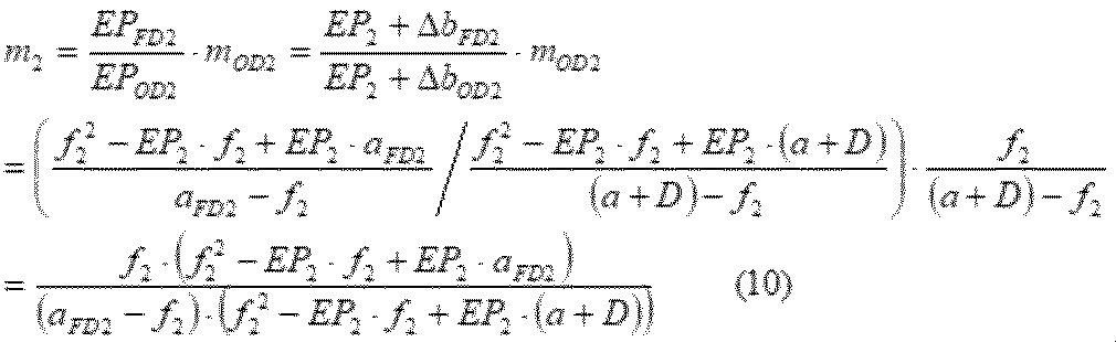
ここで、EPOD2は、第2の光学系OS2の射出瞳から、距離a+Dに測定対象が存在する場合の第2の光学像の結像位置までの距離であり、EPFD2は、第2の光学系OS2の射出瞳から第2の撮像素子S2の撮像面までの距離である。これら距離EPOD2および距離EPFD2の位置関係は、第2の撮像系IS2が構成される際において、任意の距離aFD2にある測定対象がベストピントとなるように第2の光学系OS2の位置(レンズ位置)を調整することにより決定される。また、ΔbOD2は、焦点距離f2と、第2の光学系OS2の後側主点から、距離a+Dに測定対象が存在する場合の第2の光学像の結像位置までの距離bOD2との差であり、ΔbFD2は、焦点距離f2と、第2の光学系OS2の後側主点から第2の撮像素子S2の撮像面までの距離bFD2との差であり、mOD2は、距離a+Dに測定対象が存在する場合の第2の光学像の結像位置における第2の光学像の倍率であり、aFD2は、第2の撮像素子S2の撮像面で第2の光学像がベストピントとなる場合の第2の光学系OS2の前側主点から測定対象までの距離である。
したがって、第1の光学系OS1によって第1の撮像素子S1の撮像面上に形成される第1の光学像の倍率m1と、第2の光学系OS2によって第2の撮像素子S2の撮像面上に形成される第2の光学像の倍率m2との像倍比MRは、下記式(11)で表すことができる。

ここで、Kは、係数であり、第1の撮像系IS1および第2の撮像系IS2の構成により決定される固定値f1、f2、EP1、EP2、aFD1、およびaFD2から構成される下記式(12)で表される。

上記式(11)から明らかなように、第1の光学系OS1によって第1の撮像素子S1の撮像面上に形成される第1の光学像の倍率m1と、第2の光学系OS2によって第2の撮像素子S2の撮像面上に形成される第2の光学像の倍率m2との像倍比MRは、測定対象から第1の光学系OS1の前側主点までの距離aに応じて変化することがわかる。
また、上記式(11)を距離aについて解くと、測定対象までの距離aについての一般式(13)を得ることができる。

上記式(13)中において、f1、f2、EP1、EP2、DおよびKは、第1の撮像系IS1および第2の撮像系IS2の構成により決定される固定値なので、像倍比MRを得ることができれば、測定対象から第1の光学系OS1の前側主点までの距離aを算出することができる。
図3には、上記式(13)に基づいて算出された、第1の光学系OS1によって第1の撮像素子S1の撮像面上に形成される第1の光学像の倍率m1と、第2の光学系OS2によって第2の撮像素子S2の撮像面上に形成される第2の光学像の倍率m2との像倍比MRと、測定対象までの距離aとの関係の1例が示されている。図3から明らかなように、像倍比MRの値と、測定対象までの距離aとの間には、一対一関係が成立している。一方、像倍比MRは、下記式(14)によって算出することができる。

ここで、szは、測定対象の実際のサイズ(高さまたは幅)、YFD1は、第1の光学系OS1によって第1の撮像素子S1の撮像面上に形成される第1の光学像のサイズ(像高または像幅)、YFD2は、第2の光学系OS2によって第2の撮像素子S2の撮像面上に形成される第2の光学像のサイズ(像高または像幅)である。
第1の光学像のサイズYFD1および第2の光学像のサイズYFD2は、第1の撮像素子S1および第2の撮像素子S2が第1の光学像および第2の光学像を撮像することにより取得される、第1の光学像の画像(第1の画像)および第2の光学像の画像(第2の画像)から算出することができる。そのため、実際に測定対象を第1の撮像系IS1および第2の撮像系IS2を用いて撮像することにより得られた第1の画像および第2の画像から、第1の光学像のサイズYFD1および第2の光学像のサイズYFD2を実測し、それに基づいて、第1の光学像の倍率m1と第2の光学像の倍率m2との像倍比MRを得ることができる。
なお、上記式(11)から明らかなように、第1の光学系OS1の焦点距離f1が第1の光学系OS1の焦点距離f2と等しく(f1=f2)、第1の光学系OS1の射出瞳から、測定対象が無限遠にある場合の第1の光学像の結像位置までの距離EP1が、第2の光学系OS2の射出瞳から、測定対象が無限遠にある場合の第2の光学像の結像位置までの距離EP2と等しく(EP1=EP2)、かつ、第1の光学系OS1の前側主点と、第2の光学系OS2の前側主点との間の奥行方向(光軸方向)の差Dが存在しない(D=0)場合、像倍比MRが距離aの関数として成立せず、像倍比MRは定数となる。この場合、測定対象までの距離aに応じた第1の光学像の倍率m1の変化が、認証対象者100までの距離aに応じた第2の光学像の倍率m2の変化と同一になってしまい、像倍比MRに基づいて第1の光学系OS1から測定対象までの距離aを算出することが不可能となる。
また、特別な条件として、f1≠f2、EP1≠EP2、かつD=0の場合であっても、f1=EP1かつf2=EP2の場合、像倍比MRが距離aの関数として成立せず、像倍比MRは定数となる。このような特別な場合にも、像倍比MRに基づいて第1の光学系OS1から測定対象までの距離aを算出することが不可能となる。
したがって、本発明の認証装置では、以下の3つの条件の少なくとも1つが満たされるよう、第1の光学系OS1および第2の光学系OS2が構成および配置され、これにより、測定対象までの距離aに応じた第1の光学像の倍率m1の変化が、測定対象までの距離aに応じた第2の光学像の倍率m2の変化と異なるようになっている。
(第1の条件)第1の光学系OS1の焦点距離f1と、第2の光学系OS2の焦点距離f2とが、互いに異なる(f1≠f2)
(第2の条件)第1の光学系OS1の射出瞳から、測定対象が無限遠にある場合の第1の光学像の結像位置までの距離EP1と、第2の光学系OS2の射出瞳から、測定対象が無限遠にある場合の第2の光学像の結像位置までの距離EP2とが、互いに異なる(EP1≠EP2)
(第3の条件)第1の光学系OS1の前側主点と、第2の光学系OS2の前側主点との間に奥行方向(光軸方向)の差Dが存在する(D≠0)
(第2の条件)第1の光学系OS1の射出瞳から、測定対象が無限遠にある場合の第1の光学像の結像位置までの距離EP1と、第2の光学系OS2の射出瞳から、測定対象が無限遠にある場合の第2の光学像の結像位置までの距離EP2とが、互いに異なる(EP1≠EP2)
(第3の条件)第1の光学系OS1の前側主点と、第2の光学系OS2の前側主点との間に奥行方向(光軸方向)の差Dが存在する(D≠0)
加えて、上記第1~第3の条件の少なくとも1つを満たしていたとしても、上述したような特別な場合(f1≠f2、EP1≠EP2、D=0、f1=EP1かつf2=EP2)には、像倍比MRが距離aの関数として成立せず、像倍比MRに基づいて、第1の光学系OS1から測定対象までの距離aを算出することが不可能となる。したがって、像倍比MRに基づいて第1の光学系OS1から測定対象までの距離aを算出するために、本発明の認証装置は、像倍比MRが距離aの関数として成立しているという第4の条件をさらに満たすよう構成されている。
そのため、本発明の認証装置を用いて取得された第1の画像および第2の画像から実測される第1の光学像のサイズYFD1および第2の光学像のサイズYFD2から像倍比MRを算出することにより、第1の光学系OS1の前側主点から測定対象までの距離aを算出することができる。
このように、本発明の認証装置は、実測される第1の光学像のサイズYFD1および第2の光学像のサイズYFD2に基づいて、第1の光学像の倍率m1と第2の光学像の倍率m2との像倍比MRを算出することにより、第1の光学系OS1の前側主点から測定対象までの距離aを算出する。
本発明の認証装置では、測定対象は、図4に示すように、本発明の認証装置の認証の対象となる認証対象者100の顔の複数の箇所である。これにより、本発明の認証装置では、認証対象者100の顔の複数の箇所(例えば、眼、鼻、口、耳等の顔のパーツ)のそれぞれまでの距離aが算出され、これに基づき、認証対象者100の顔の3次元情報が生成される。このようにして生成された認証対象者100の顔の3次元情報は、3次元顔認証に利用される。
以下、上述の原理を利用して、認証対象者100の顔の複数の箇所のそれぞれまでの距離aを算出することにより、認証対象者100の顔の3次元情報を生成し、さらに、生成した顔の3次元情報を用いて3次元顔認証を実行可能に構成された本発明の認証装置を、添付図面に示す好適な実施形態に基づいて詳述する。
<第1実施形態>
最初に、図4および5を参照して、本発明の認証装置の第1実施形態を説明する。図4は、本発明の第1実施形態に係る認証装置を概略的に示すブロック図である。図5は、図4に示す認証装置の第1の撮像系および第2の撮像系の撮像範囲を示すための概略図である。
最初に、図4および5を参照して、本発明の認証装置の第1実施形態を説明する。図4は、本発明の第1実施形態に係る認証装置を概略的に示すブロック図である。図5は、図4に示す認証装置の第1の撮像系および第2の撮像系の撮像範囲を示すための概略図である。
図4に示す認証装置1は、認証装置1の制御を行う制御部2と、認証対象者100からの光を集光し、認証対象者100の第1の光学像を形成するための第1の光学系OS1および第1の光学系OS1によって形成された第1の光学像を撮像するための第1の撮像素子S1を有する第1の撮像系IS1と、認証対象者100からの光を集光し、認証対象者100の第2の光学像を形成するための第2の光学系OS2および第2の光学系OS2によって形成された第2の光学像を撮像するための第2の撮像素子S2を有する第2の撮像系IS2と、第1の光学像の倍率m1と第2の光学像の倍率m2との像倍比MRと、認証対象者100の顔の複数の箇所のそれぞれまでの距離aとを関連付ける関連付情報を記憶している関連付情報記憶部3と、第1の光学像および第2の光学像に基づいて、認証対象者100の顔の複数の箇所のそれぞれまでの距離aを算出するための距離算出部4と、距離算出部4が算出した認証対象者100の顔の複数の箇所のそれぞれまでの距離に基づいて、認証対象者100の顔の3次元情報を生成するための3次元情報生成部5と、認証のために必要な認証情報を記憶している認証情報記憶部6と、認証対象者100の認証処理を実行するための認証部7と、使用者による操作を入力するための操作部8と、液晶パネル等の任意の情報を表示するための表示部9と、外部デバイスとの通信を実行するための通信部10と、認証装置1の各コンポーネント間のデータや指示の授受を実行するためのデータバス11と、を備えている。
本実施形態の認証装置1は、像倍比MRに基づいて測定対象(すなわち、認証対象者100の顔の複数の箇所のそれぞれ)までの距離aを算出するために要求される上述の3つの条件の内、第1の光学系OS1の焦点距離f1と、第2の光学系OS2の焦点距離f2とが、互いに異なる(f1≠f2)という第1の条件が満たされるよう、第1の光学系OS1および第2の光学系OS2が構成されていることを特徴とする。一方、本実施形態では、第1の光学系OS1および第2の光学系OS2は、上述の3つの条件の内、その他の2つの条件(EP1≠EP2およびD≠0)を満たすように構成および配置されていない。さらに、本実施形態の認証装置1は、像倍比MRが距離aの関数として成立しているという第4の条件が満たされるよう構成されている。
そのため、像倍比MRを用いて測定対象(すなわち、認証対象者100の顔の複数の箇所のそれぞれ)までの距離aを算出するための上記一般式(13)は、EP1=EP2=EPおよびD=0の条件により単純化され、下記式(15)で表すことができる。

ここで、係数Kは、下記式(16)で表される。

本実施形態の認証装置1は、第1の撮像系IS1および第2の撮像系IS2によって認証対象者100を撮像することにより第1の光学像の倍率m1と第2の光学像の倍率m2との像倍比MRを算出し、さらに、上記式(15)を用いて、認証対象者100の顔の複数の箇所のそれぞれまでの距離aを算出する。本実施形態の認証装置1は、算出した認証対象者100の顔の複数の箇所のそれぞれまでの距離aに基づいて、認証対象者100の顔の3次元情報を生成し、3次元顔認証を実行する。
以下、認証装置1の各コンポーネントについて詳述する。制御部2は、データバス11を介して、各コンポーネントとの間の各種データや各種指示の授受を行い、認証装置1の制御を実行する。制御部2は、演算処理を実行するためのプロセッサーと、認証装置1の制御を行うために必要なデータ、プログラム、モジュール等を保存しているメモリーとを備えており、制御部2のプロセッサーは、メモリー内に保存されているデータ、プログラム、モジュール等を用いることにより、認証装置1の制御を実行する。また、制御部2のプロセッサーは、認証装置1の各コンポーネントを用いることにより、所望の機能を提供することができる。例えば、制御部2のプロセッサーは、距離算出部4を用いることにより、第1の撮像系IS1および第2の撮像系IS2によって撮像された第1の光学像および第2の光学像に基づいて、認証対象者100の顔の複数の箇所のそれぞれまでの距離aを算出するための処理を実行することができる。
制御部2のプロセッサーは、例えば、1つ以上のマイクロプロセッサー、マイクロコンピューター、マイクロコントローラー、デジタル信号プロセッサー(DSP)、中央演算処理装置(CPU)、メモリーコントロールユニット(MCU)、画像処理用演算処理装置(GPU)、状態機械、論理回路、特定用途向け集積回路(ASIC)、またはこれらの組み合わせ等のコンピューター可読命令に基づいて信号操作等の演算処理を実行する演算ユニットである。特に、制御部2のプロセッサーは、制御部2のメモリー内に保存されているコンピューター可読命令(例えば、データ、プログラム、モジュール等)をフェッチし、信号操作および制御を実行するよう構成されている。
制御部2のメモリーは、揮発性記憶媒体(例えば、RAM、SRAM、DRAM)、不揮発性記憶媒体(例えば、ROM、EPROM、EEPROM、フラッシュメモリー、ハードディスク、光ディスク、CD-ROM、デジタル多用途ディスク(DVD)、磁気カセット、磁気テープ、磁気ディスク)、またはこれらの組み合わせを含む着脱式または非着脱式のコンピューター可読媒体である。
第1の撮像系IS1および第2の撮像系IS2のそれぞれは、認証対象者100を撮像するよう構成および配置されている。第1の撮像系IS1の第1の光学系OS1は、認証対象者100からの光を集光し、第1の撮像系IS1の第1の撮像素子S1の撮像面上に第1の光学像を形成する機能を有する。第2の撮像系IS2の第2の光学系OS2は、認証対象者100からの光を集光し、第2の撮像系IS2の第2の撮像素子S2の撮像面上に第2の光学像を形成するための機能を有する。第1の光学系OS1および第2の光学系OS2は、1つ以上のレンズと絞り等の光学素子から構成されている。また、図示のように、第1の光学系OS1の光軸と、第2の光学系OS2の光軸は、平行であるが、一致していない。
上述のように、第1の光学系OS1および第2の光学系OS2は、第1の光学系OS1の焦点距離f1と第2の光学系OS2の焦点距離f2とが、互いに異なるよう(f1≠f2)、構成されている。これにより、第1の光学系OS1によって形成される第1の光学像の倍率m1の認証対象者100の顔の複数の箇所のそれぞれまでの距離aに応じた変化が、第2の光学系OS2によって形成される第2の光学像の倍率m2の認証対象者100の顔の複数の箇所のそれぞれまでの距離aに応じた変化と異なるようになっている。
また、本実施形態では、第1の光学系OS1および第2の光学系OS2は、第1の光学系OS1の焦点距離f1が、第2の光学系OS2の焦点距離f2よりも長くなるよう(f1>f2)、構成されている。
なお、本実施形態における第1の光学系OS1の構成および第2の光学系OS2の構成および配置は、上述の第1の条件(f1≠f2)が満たされており、それにより、認証対象者100の顔の複数の箇所のそれぞれまでの距離aに対する第1の光学像の倍率m1の変化と、認証対象者100の顔の複数の箇所のそれぞれまでの距離aに対する第2の光学像の倍率m2の変化とが、互いに異なるようになっていれば、如何なる態様であってもよい。
第1の撮像系IS1の第1の撮像素子S1は、第1の光学系OS1によって形成された第1の光学像を撮像し、第1の画像を取得する機能を有している。同様に、第2の撮像系IS2の第2の撮像素子S2は、第2の光学系OS2によって形成された第2の光学像を撮像し、第2の画像を取得する機能を有している。
第1の撮像素子S1および第2の撮像素子S2は、ベイヤー配列等の任意のパターンで配列されたRGB原色系カラーフィルターやCMY補色系カラーフィルターのようなカラーフィルターを有するCMOS画像センサーやCCD画像センサー等のカラー撮像素子であってもよいし、そのようなカラーフィルターを有さない白黒撮像素子であってもよい。
第1の光学系OS1によって、第1の撮像素子S1の撮像面上に第1の光学像が形成され、第1の撮像素子S1によって、カラーまたは白黒の第1の画像信号が取得される。取得された第1の画像は、データバス11を介して、制御部2、距離算出部4、および認証部7に送られる。同様に、第2の光学系OS2によって、第2の撮像素子S2の撮像面上に第2の光学像が形成され、第2の撮像素子S2によって、カラーまたは白黒の第2の画像が取得される。取得された第2の画像は、データバス11を介して、制御部2、距離算出部4、および認証部7に送られる。距離算出部4に送られた第1の画像および第2の画像は、認証対象者100の顔の複数の箇所のそれぞれまでの距離aを算出するために用いられる。一方、認証部7に送られた第1の画像および第2の画像は、認証対象者100の2次元顔認証および/または虹彩認証を実行するために用いられる。また、制御部2に送られた第1の画像および第2の画像は、表示部9による画像表示や通信部10による画像の通信のために用いられる。
なお、図示の形態では、第1の撮像系IS1および第2の撮像系IS2が別々の筐体内において構成されているが、本発明はこれに限られない。第1の撮像系IS1および第2の撮像系IS2が同一の筐体内において構成されているような態様も、本発明の範囲内である。
関連付情報記憶部3は、第1の光学像の倍率m1と第2の光学像の倍率m2との像倍比MR(m2/m1)と、第1の光学系OS1の前側主点から認証対象者100の顔の複数の箇所のそれぞれまでの距離(被写体距離)aとを関連付ける関連付情報を記憶するための任意の不揮発性記録媒体(例えば、ハードディスク、フラッシュメモリー)である。関連付情報記憶部3に保存されている関連付情報は、第1の光学像の倍率m1と第2の光学像の倍率m2との像倍比MR(m2/m1)から、認証対象者100の顔の複数の箇所のそれぞれまでの距離aを算出するための情報である。
典型的には、関連付情報記憶部3に保存されている関連付情報は、像倍比MRに基づいて認証対象者100の顔の複数の箇所のそれぞれまでの距離aを算出するための上記式(15)(または、一般式(13))、並びに、該式中の第1の光学系OS1および第2の光学系OS2の構成および配置によって決定される上述の固定値(上記式(15)用であれば、固定値であるf1、f2、EP、およびK)である。代替的に、関連付情報記憶部3に保存されている関連付情報は、像倍比MRと認証対象者100の顔の複数の箇所のそれぞれまでの距離aとを一意に対応づけたルックアップテーブルであってもよい。関連付情報記憶部3に保存されているこのような関連付情報を参照することにより、像倍比MRに基づいて認証対象者100の顔の複数の箇所のそれぞれまでの距離aを算出することが可能となる。
距離算出部4は、第1の撮像系IS1および第2の撮像系IS2によって撮像された第1の光学像および第2の光学像に基づいて、認証対象者100の顔の複数の箇所のそれぞれまでの距離aを算出する機能を有している。より具体的には、距離算出部4は、第1の光学像の倍率m1と第2の光学像の倍率m2との像倍比MRに基づいて、認証対象者100の顔の複数の箇所のそれぞれまでの距離aを算出する機能を有している。距離算出部4は、第1の撮像系IS1の第1の撮像素子S1から第1の画像を受信し、さらに、第2の撮像系IS2の第2の撮像素子S2から第2の画像を受信する。
その後、距離算出部4は、第1の画像および第2の画像に対して、Cannyのようなフィルター処理を施し、第1の画像内における第1の光学像の複数のエッジ部および第2の画像内における第2の光学像の複数のエッジ部を抽出する。距離算出部4は、抽出した第1の光学像の複数のエッジ部に基づいて、第1の光学像の複数の箇所のサイズ(像幅または像高)YFD1を算出し、さらに、抽出した第2の光学像のエッジ部に基づいて、第2の光学像の複数の箇所のサイズ(像幅または像高)YFD2を算出する。
距離算出部4は、サイズYFD1、YFD2を算出するために用いる複数のエッジ部の組み合わせを変更することによって、第1の光学像および第2の光学像の複数の個所のサイズYFD1、YFD2を取得する。
例えば、距離算出部4は、抽出した複数のエッジ部の内、高さ方向に隣り合うエッジ部を選択し、それらの離間距離を測定することにより、光学像中の任意の箇所の像高を取得することができる。同様に、距離算出部4は、抽出した複数のエッジ部の内、幅方向に隣り合うエッジ部を選択し、それらの離間距離を測定することにより、光学像中の任意の箇所の像幅を取得することができる。
距離算出部4による、抽出した複数のエッジ部の選択は、認証対象者100の顔に相当するエリアに位置するエッジ部の全てまたはいくつかの組み合わせが網羅されるように実行される。なお、距離算出部4は、抽出されたエッジ部の全てまたはいくつかの組み合わせを網羅するよう、抽出した複数のエッジ部の選択を実行してもよい。このようにして、距離算出部4は、第1の光学像の複数の箇所のそれぞれのサイズYFD1および第2の光学像の複数の箇所のそれぞれのサイズYFD2を取得する。
その後、距離算出部4は、算出した第1の光学像の複数の箇所のそれぞれのサイズYFD1および第2の光学像の対応する箇所のサイズYFD2に基づき、上記式(14)MR=YFD2/YFD1によって、第1の光学像の複数の箇所のそれぞれの倍率m1と第2の光学像の対応する箇所のそれぞれの倍率m2との像倍比MRを算出する。各箇所の像倍比MRが算出されると、距離算出部4は、関連付情報記憶部3に保存されている関連付情報を参照し、像倍比MRに基づいて、認証対象者100の顔の複数の箇所のそれぞれまでの距離aを算出(特定)する。
3次元情報生成部5は、距離算出部4が算出した認証対象者100の顔の複数の箇所のそれぞれまでの距離aに基づいて、認証対象者100の顔の3次元情報を生成する機能を有している。3次元情報生成部5は、距離算出部4から認証対象者100の顔の複数の箇所のそれぞれまでの距離aを受信すると、それに基づいて、認証対象者100の顔の3次元グリッド(3次元メッシュ)およびテクスチャを生成し、認証対象者100の顔を3次元モデル化する。
なお、距離算出部4が算出した認証対象者100の顔の複数の箇所のそれぞれまでの距離aが、認証対象者100の顔を3次元モデル化するのに不十分である場合には、3次元情報生成部5は、バイリニア補間、バイキュービック補間、最近傍補間等の任意の補間技術を用いて、認証対象者100の顔の高さ(奥行)情報の補間を実行し、認証対象者100の顔を3次元モデル化する。
その後、3次元情報生成部5は、認証対象者100の顔の3次元モデルから、認証対象者100の顔の3次元特徴を、認証対象者100の顔の3次元情報として抽出する。顔の3次元モデルから抽出される顔の3次元情報としては、例えば、鼻の高さ、鼻の形状(鼻尖の向きや形、鼻背の形や高さ、鼻翼の形等)、眼の窪みの深さ、顔の各部位(眼、鼻、口、耳、眉等)間の奥行方向の離間距離を挙げることができる。このような認証対象者100の顔の3次元情報は、後述する認証部7によって実行される3次元顔認証において用いられる。
認証情報記憶部6は、認証対象者100の認証を実行するために必要な認証情報を記憶している任意の不揮発性記録媒体(例えば、ハードディスク、フラッシュメモリー)である。本発明の認証装置1の管理者等は、事前に、認証を許可された人物を、本発明の認証装置1または同等の機能を有する撮像装置を用いて撮像することにより、認証を許可された人物の3次元情報、第1の画像、および第2の画像を取得し、これらを認証情報として、認証情報記憶部6内に登録する。
後述する認証部7による認証対象者100に対する認証処理の実行時に、取得された認証対象者100の3次元情報、第1の画像、および/または、第2の画像が、認証情報記憶部6に保存されている認証情報と照合され、3次元顔認証、2次元顔認証、および/または虹彩認証が実行される。
なお、図示の形態では、認証情報記憶部6は、認証装置1の内部に設けられているが、本発明はこれに限られない。例えば、認証情報記憶部6は、インターネット、ローカルエリアネットワーク(LAN)、広域ネットワーク(WAN)等の種々の有線または無線ネットワークを介して認証装置1に接続された外部サーバーや外部ストレージデバイスであってもよい。また、認証情報記憶部6が外部サーバーや外部ストレージデバイスである場合、1つ以上の認証情報記憶部6が複数の認証装置1間で共用されていてもよい。この場合、認証装置1は、認証対象者100に対する認証が実行されるたびに、通信部10を用いて、外部に設けられた認証情報記憶部6と通信を行い、認証対象者100に対する認証を実行する。
認証部7は、3次元情報生成部5が算出した認証対象者100の顔の3次元情報を用いて、認証対象者100の3次元顔認証を実行可能に構成されている。より具体的には、認証部7は、3次元情報生成部5が算出した認証対象者100の顔の3次元情報と、認証情報記憶部6に事前に登録されている認証情報に含まれる顔の3次元情報とを比較することにより、認証対象者100の3次元顔認証を実行する。
認証部7は、認証対象者100の顔の3次元情報に含まれる鼻の高さや眼の窪みの深さといった複数の要素のいずれか1つが、認証情報記憶部6に事前に登録されている認証情報の顔の3次元情報の対応する要素と一致すれば、3次元顔認証が成功したと判断してもよいし、複数の要素の全てが、認証情報記憶部6に事前に登録されている認証情報の顔の3次元情報の対応する要素と一致した場合に、3次元顔認証が成功したと判断してもよい。
また、認証部7は、前述した3次元顔認証に加えて、第1の撮像系IS1および第2の撮像系IS2から受信した第1の画像および第2の画像を用いて、認証対象者100の虹彩認証および2次元顔認証を実行可能に構成されている。具体的には、認証部7は、第1の画像および/または第2の画像から、顔の2次元特徴量および眼の虹彩情報を抽出し、抽出した顔の2次元特徴量および眼の虹彩情報を用いて、認証対象者100の虹彩認証および2次元顔認証を実行可能に構成されている。認証部7が第1の画像および/または第2の画像から、顔の2次元特徴量および眼の虹彩情報を抽出する方法は特に限定されず、本分野において既知の様々なアルゴリズムを用いて、顔の2次元特徴量および眼の虹彩情報を抽出することができる。
認証部7は、第1の撮像系IS1および第2の撮像系IS2から受信した第1の画像および/または第2の画像から抽出された認証対象者100の顔の2次元特徴量と、認証情報記憶部6に事前に登録されている認証情報に含まれる第1の画像および/または第2の画像から抽出された顔の2次元特徴量とを比較し、認証対象者100の2次元顔認証を実行可能に構成されている。認証部7によって実行される2次元顔認証の方法は特に限定されないが、例えば、認証部7は、固有顔法、線形判別分析、グラフマッチング法、周波数解析法、ニューラルネットワーク法、Viola-Jones法等の任意の2次元顔認証アルゴリズムを用いて、認証対象者100の2次元顔認証を実行することができる。
また、認証部7は、第1の撮像系IS1および第2の撮像系IS2から受信した第1の画像および/または第2の画像から抽出された認証対象者100の眼の虹彩情報と、認証情報記憶部6に事前に登録されている認証情報に含まれる第1の画像および/または第2の画像から抽出された眼の虹彩情報とを比較し、認証対象者100の虹彩認証を実行可能に構成されている。認証部7によって実行される虹彩認証の方法は特に限定されないが、例えば、認証部7は、Dangmanのアルゴリズム等の任意の虹彩認証アルゴリズムを用いて、認証対象者100の虹彩認証を実行することができる。
なお、本実施形態では、上述のように、第1の光学系OS1および第2の光学系OS2は、第1の光学系OS1の焦点距離f1が、第2の光学系OS2の焦点距離f2よりも長くなるよう(f1>f2)、構成されている。そのため、本実施形態の認証装置1は、簡易に異なる画角の2つの画像(第1の画像と第2の画像)を同時に取得することができる。具体的には、本実施形態において、第1の撮像系IS1により取得される第1の画像の画角は、第2の撮像系IS2により取得される第2の画像の画角よりも狭く、さらに、第1の撮像系IS1により取得される第1の画像の倍率は、第2の撮像系IS2により取得される第2の画像の倍率よりも高い。
虹彩認証では、眼の微細な構造である虹彩が用いられるので、虹彩認証に用いられる画像では、認証対象者100の眼が拡大され、大きく写っていることが好ましい。第1の画像と第2の画像を比較すると、第1の画像は、狭画角および高倍率である。そのため、虹彩認証は、狭画角および高倍率である第1の画像を用いて、実行される。また、より広い範囲の画像を必要とするが、虹彩認証と比較して微細な構造に関する情報を必要としない2次元顔認証は、広画角および低倍率である第2の画像を用いて、実行される。
本実施形態では、図5(a)および図5(b)に示すように、第1の撮像系IS1は、第1の撮像系IS1の撮像範囲(図5(a)および図5(b)中に点線で示されている範囲)中に、認証対象者100の眼を含む認証対象者100の眼の周辺領域のみが含まれるように、構成および配置される。また、本実施形態では、第2の撮像系IS2は、第2の撮像系IS2の撮像範囲(図5(a)および図5(b)中に一点鎖線で示されている範囲)内に、認証対象者100の顔の全体が含まれるように、構成および配置される。
そのため、本実施形態の認証部7は、第1の撮像系IS1が取得した第1の画像を用いて認証対象者100の虹彩認証を実行し、さらに、第2の撮像系IS2が取得した第2の画像を用いて認証対象者100の2次元顔認証を実行する。このような構成により、認証対象者100の虹彩認証および2次元顔認証の精度を高めることができる。
このように、認証部7は、3次元顔認証、2次元顔認証、および虹彩認証の3つの認証を実行可能に構成されている。認証部7は、認証装置1に対して事前に設定されているセキュリティレベル(例えば、「高」、「中」、および「低」)に応じて、これら3つの認証の少なくとも1つを実行することができる。認証装置1のセキュリティレベルは、認証装置1の管理者等により、操作部8を用いて、手動で設定されてもよいし、認証装置1が、通信部10を介して、管理者等の携帯電話、スマートフォン、ノートパソコン、ラップトップコンピューター等の外部デバイスからセキュリティレベル設定命令を受信し、それに基づいて、セキュリティレベルが設定されてもよい。
例えば、認証装置1のセキュリティレベルが「高」に設定されている場合、認証部7は、認証対象者100の3次元顔認証および虹彩認証の双方を実行する。この場合、3次元顔認証および虹彩認証の双方を実行するために、認証に要する処理時間が長くなるが、3次元顔認証を実行することにより、写真によるなりすましを見破ることができ、さらに、3次元顔認証と虹彩認証による2重のチェックを実行することができ、認証対象者100の認証の精度を高めることができる。この場合、認証部7は、3次元顔認証と虹彩認証の双方が成功した場合にのみ、認証対象者100の認証が成功したと判断する。
また、虹彩認証が成功したにも関わらず、3次元顔認証が失敗した場合には、写真によるなりすましが実行された可能性が高い。そのため、虹彩認証が成功し、3次元顔認証が失敗した場合には、認証部7は、認証対象者100の認証が失敗したことに加え、写真によるなりすましが実行された可能性が高いと判断する。
また、認証装置1のセキュリティレベルが「中」に設定されている場合、認証部7は、認証対象者100の2次元顔認証および虹彩認証の双方を実行する。2次元顔認証は、顔の3次元モデルの処理を必要とする3次元顔認証よりも処理時間が短いため、セキュリティレベルが「高」に設定されている場合と比較して、認証に要する処理時間を短くすることができる。また、2次元顔認証と虹彩認証の2重のチェックを実行することができ、認証対象者100の認証の精度を高めることができる。この場合、認証部7は、2次元顔認証と虹彩認証の双方が成功した場合にのみ、認証対象者100の認証が成功したと判断する。
また、認証装置1のセキュリティレベルが「低」に設定されている場合、認証部7は、認証対象者100の2次元顔認証または虹彩認証を実行する。この場合、認証部7は、2次元顔認証と虹彩認証のいずれか一方が成功した場合に、認証対象者100の認証が成功したと判断する。2次元顔認証と虹彩認証のいずれか一方が成功すれば、認証対象者100の認証が成功したと判断されるため、認証対象者100の認証に要する処理時間をさらに短くすることができる。2次元顔認証および虹彩認証の実行順番は特に限定されないが、例えば、認証部7は、最初に、2次元顔認証を実行し、認証対象者100の顔の一部がマスク等で隠れていて、2次元顔認証が失敗した場合に、虹彩認証を実行するよう構成されていてもよい。
認証部7による認証対象者100の認証結果(判断結果)は、データバス11を介して、制御部2に送られる。制御部2は、受信した認証結果を、通信部10を介して、外部デバイス(例えば、ドアのロック解除装置、任意のアプリケーションを提供する端末等)に送信する。これにより、外部デバイスは、受信した認証結果に応じた処理を実行することができる。例えば、外部デバイスは、認証対象者100の認証が成功したとの結果を受信した場合には、ドアのロックのような物理的なロックまたはソフトウェアのロックを解除、または、任意のアプリケーションの起動を許可し、認証対象者100の認証が失敗したとの結果を受信した場合には、ドアのロックのような物理的なロックまたはソフトウェアのロックを維持、または、任意のアプリケーションの起動を許可しない。また、例えば、外部デバイスは、写真によるなりすましが実行されたとの結果を受信した場合には、セキュリティ警告メッセージを、外部デバイスや認証装置1の管理者等に通知する。
このように、認証部7は、事前に設定されたセキュリティレベルに応じて、実行する認証処理を選択するので、本発明の認証装置1を様々なセキュリティ用途に用いることが可能となる。
図4に戻り、操作部8は、認証装置1のユーザーや管理者等が操作を実行するために用いられる。操作部8は、認証装置1のユーザーが操作を実行することができれば特に限定されず、例えば、マウス、キーボード、テンキー、ボタン、ダイヤル、レバー、タッチパネル等を操作部8として用いることができる。操作部8は、認証装置1のユーザーによる操作に応じた信号を制御部2のプロセッサーに送信する。例えば、上述のように、認証装置1の管理者等は、操作部8を用いて、認証装置1のセキュリティレベルを設定することができる。
通信部10は、有線通信または無線通信による、認証装置1に対するデータの入力または認証装置1から外部デバイスへのデータの出力を行う機能を有している。通信部10は、インターネットのようなネットワークに接続可能に構成されていてもよい。この場合、認証装置1は、通信部10を用いることにより、外部に設けられたウェブサーバーやデータサーバーのような外部デバイスと通信を行うことができる。
このように、本実施形態の認証装置1では、第1の光学系OS1および第2の光学系OS2が、第1の光学系OS1の焦点距離f1と第2の光学系OS2の焦点距離f2とが、互いに異なるよう(f1≠f2)、構成されており、これにより、認証対象者100の顔の複数の箇所のそれぞれまでの距離aに対する第1の光学像の倍率m1の変化と、認証対象者100の顔の複数の箇所のそれぞれまでの距離aに対する第2の光学像の倍率m2の変化とが、互いに異なるようになっている。そのため、本実施形態の認証装置1は、第1の光学像の倍率m1と第2の光学像の倍率m2との像倍比MR(m2/m1)に基づいて、認証対象者100の顔の複数の箇所のそれぞれまでの距離aを一意に算出することができる。さらに、本実施形態の認証装置1は、算出した認証対象者100の顔の複数の箇所のそれぞれまでの距離aに基づいて、認証対象者100の顔の3次元情報を生成し、認証対象者100の3次元顔認証を実行することができる。
<第2実施形態>
次に、図6を参照して、本発明の第2実施形態に係る認証装置について詳述する。図6は、本発明の第2実施形態に係る認証装置の第1の撮像系と第2の撮像系を概略的に示すブロック図である。
次に、図6を参照して、本発明の第2実施形態に係る認証装置について詳述する。図6は、本発明の第2実施形態に係る認証装置の第1の撮像系と第2の撮像系を概略的に示すブロック図である。
以下、第2実施形態の認証装置1について、第1実施形態の認証装置1との相違点を中心に説明し、同様の事項については、その説明を省略する。本実施形態の認証装置1は、第1の光学系OS1および第2の光学系OS2の構成が変更されている点を除き、第1実施形態の認証装置1と同様である。
本実施形態の認証装置1は、像倍比MRに基づいて、測定対象(認証対象者100の顔の複数の箇所のそれぞれ)までの距離aを算出するために要求される上述の3つの条件の内、第1の光学系OS1の射出瞳から、測定対象が無限遠にある場合の第1の光学像の結像位置までの距離EP1と、第2の光学系OS2の射出瞳から、測定対象が無限遠にある場合の第2の光学像の結像位置までの距離EP2とが、互いに異なる(EP1≠EP2)という第2の条件が満たされるよう、第1の光学系OS1および第2の光学系OS2が構成されていることを特徴とする。一方、本実施形態では、第1の光学系OS1および第2の光学系OS2は、上述の3つの条件の内、その他の2つの条件(f1≠f2およびD≠0)を満たすように構成および配置されていない。さらに、本実施形態の認証装置1は、像倍比MRが距離aの関数として成立しているという第4の条件が満たされるよう構成されている。
そのため、像倍比MRに基づいて、測定対象(認証対象者100の顔の複数の箇所のそれぞれ)までの距離aを算出するための上記一般式(13)は、f1=f2=fおよびD=0の条件により単純化され、下記式(17)で表すことができる。

ここで、係数Kは、下記式(18)で表される。

このように、本実施形態の認証装置1では、第1の光学系OS1の射出瞳から、測定対象(認証対象者100の顔の複数の箇所のそれぞれ)が無限遠にある場合の第1の光学像の結像位置までの距離EP1と、第2の光学系OS2の射出瞳から、測定対象が無限遠にある場合の第2の光学像の結像位置までの距離EP2とが、互いに異なるよう(EP1≠EP2)、第1の光学系OS1および第2の光学系OS2が構成されており、これにより、認証対象者100の顔の複数の箇所のそれぞれまでの距離aに対する第1の光学像の倍率m1の変化と、認証対象者100の顔の複数の箇所のそれぞれまでの距離aに対する第2の光学像の倍率m2の変化とが、互いに異なるようになっている。そのため、本実施形態の認証装置1は、第1の光学像の倍率m1と第2の光学像の倍率m2との像倍比MR(m2/m1)に基づいて、認証対象者100の顔の複数の箇所のそれぞれまでの距離aを一意に算出することができる。さらに、本実施形態の認証装置1は、算出した認証対象者100の顔の複数の箇所のそれぞれまでの距離aに基づいて、認証対象者100の顔の3次元情報を生成し、認証対象者100の3次元顔認証を実行することができる。
本実施形態によっても、上述の第1実施形態と同様の効果を発揮することができる。なお、本実施形態における第1の光学系OS1および第2の光学系OS2の構成および配置は、上述の第2の条件(EP1≠EP2)が満たされており、それにより、認証対象者100の顔の複数の箇所のそれぞれまでの距離aに対する第1の光学像の倍率m1の変化と、認証対象者100の顔の複数の箇所のそれぞれまでの距離aに対する第2の光学像の倍率m2の変化とが、互いに異なるようになっていれば、如何なる態様であってもよい。
また、本実施形態では、第1の光学系OS1の焦点距離f1と、第2の光学系OS2の焦点距離f2は同一なので(f1=f2=f)、第1の撮像系IS1によって取得される第1の画像および第2の撮像系IS2によって取得される第2の画像のいずれを用いて、認証対象者100の虹彩認証が実行されてもよい。
<第3実施形態>
次に、図7を参照して、本発明の第3実施形態に係る認証装置について詳述する。図7は、本発明の第3実施形態に係る認証装置の第1の撮像系と第2の撮像系を概略的に示すブロック図である。
次に、図7を参照して、本発明の第3実施形態に係る認証装置について詳述する。図7は、本発明の第3実施形態に係る認証装置の第1の撮像系と第2の撮像系を概略的に示すブロック図である。
以下、第3実施形態の認証装置1について、第1実施形態の認証装置1との相違点を中心に説明し、同様の事項については、その説明を省略する。本実施形態の認証装置1は、第1の光学系OS1および第2の光学系OS2の構成および配置が変更されている点を除き、第1実施形態の認証装置1と同様である。
本実施形態の認証装置1は、像倍比MRに基づいて測定対象(認証対象者100の顔の複数の箇所のそれぞれ)までの距離aを算出するために要求される上述の3つの条件の内、第1の光学系OS1の前側主点と、第2の光学系OS2の前側主点との間に奥行方向(光軸方向)の差Dが存在する(D≠0)という第3の条件が満たされるよう、第1の光学系OS1および第2の光学系OS2が構成および配置されていることを特徴とする。一方、本実施形態では、第1の光学系OS1および第2の光学系OS2は、上述の3つの条件の内、その他の2つの条件(f1≠f2およびEP1≠EP2)を満たすように構成されていない。さらに、本実施形態の認証装置1は、像倍比MRが距離aの関数として成立しているという第4の条件が満たされるよう構成されている。
そのため、像倍比MRに基づいて、測定対象(認証対象者100の顔の複数の箇所のそれぞれ)までの距離aを算出するための上記一般式(13)は、f1=f2=fおよびEP1=EP2=EPの条件により単純化され、下記式(19)で表すことができる。

ここで、係数Kは、下記式(20)で表される。

このように、本実施形態の認証装置1では、第1の光学系OS1および第2の光学系OS2が、第1の光学系OS1の前側主点と、第2の光学系OS2の前側主点との間に奥行方向(光軸方向)の差Dが存在するよう(D≠0)、構成および配置されており、これにより、認証対象者100の顔の複数の箇所のそれぞれまでの距離aに対する第1の光学像の倍率m1の変化と、認証対象者100の顔の複数の箇所のそれぞれまでの距離aに対する第2の光学像の倍率m2の変化とが、互いに異なるようになっている。そのため、本実施形態の認証装置1は、第1の光学像の倍率m1と第2の光学像の倍率m2との像倍比MR(m2/m1)に基づいて、認証対象者100の顔の複数の箇所のそれぞれまでの距離aを一意に算出することができる。さらに、本実施形態の認証装置1は、算出した認証対象者100の顔の複数の箇所のそれぞれまでの距離aに基づいて、認証対象者100の顔の3次元情報を生成し、認証対象者100の3次元顔認証を実行することができる。
本実施形態によっても、上述の第1実施形態と同様の効果を発揮することができる。なお、本実施形態における第1の光学系OS1の構成および第2の光学系OS2の構成および配置は、上述の第3の条件(D≠0)が満たされており、それにより、認証対象者100の顔の複数の箇所のそれぞれまでの距離aに対する第1の光学像の倍率m1の変化と、認証対象者100の顔の複数の箇所のそれぞれまでの距離aに対する第2の光学像の倍率m2の変化とが、互いに異なるようになっていれば、如何なる態様であってもよい。
また、本実施形態では、第1の光学系OS1の焦点距離f1と、第2の光学系OS2の焦点距離f2は同一なので(f1=f2=f)、第1の撮像系IS1によって取得される第1の画像および第2の撮像系IS2によって取得される第2の画像のいずれを用いて、認証対象者100の虹彩認証が実行されてもよい。
<第4実施形態>
次に、図8を参照して、本発明の第4実施形態に係る認証装置について詳述する。図8は、本発明の第4実施形態に係る認証装置の第1の撮像系、第2の撮像系、および赤外光照射部を概略的に示すブロック図である。
次に、図8を参照して、本発明の第4実施形態に係る認証装置について詳述する。図8は、本発明の第4実施形態に係る認証装置の第1の撮像系、第2の撮像系、および赤外光照射部を概略的に示すブロック図である。
以下、第4実施形態の認証装置について、第1実施形態の認証装置との相違点を中心に説明し、同様の事項については、その説明を省略する。本実施形態の認証装置1は、認証装置1が認証対象者100に対して赤外光を照射する赤外光照射部12をさらに備える点、および、第1の撮像素子S1および第2の撮像素子S2の少なくとも一方が赤外光を撮像可能に構成されている点を除き、第1実施形態の認証装置と同様である。
赤外光照射部12は、認証装置1のデータバス11に接続され、認証装置1の制御部2のプロセッサーからの制御に応じて、認証対象者100に対して赤外光を照射する機能を有する。赤外光照射部12は、認証装置1の制御部2のプロセッサーからの制御に応じて、認証対象者100に対して赤外光を照射することができれば特に限定されず、例えば、赤外光LEDを赤外光照射部12として用いることができる。
本実施形態における、第1の撮像系IS1の第1の撮像素子S1および第2の撮像系IS2の第2の撮像素子S2の少なくとも一方は、赤外光を撮像可能に構成されている。本実施形態では、第1の撮像系IS1および第2の撮像系IS2による認証対象者100の撮像時に、制御部2のプロセッサーからの制御に応じて、赤外光照射部12が認証対象者100に対して赤外光を照射する。第1の撮像素子S1および第2の撮像系IS2の第2の撮像素子S2の少なくとも一方は、赤外光を撮像可能に構成されているので、第1の撮像系IS1および第2の撮像系IS2は、暗所であっても、認証対象者100の赤外線画像を取得することができる。
虹彩認証のために眼の画像を取得する際に、可視光を認証対象者100の眼に直接照射すると眩しく、認証時の認証対象者100の負担が大きい。さらに、眼の虹彩の反射率は、赤外光領域において高い。そのため、認証対象者100の負担を低減し、さらに、虹彩認証の精度を上げるためには、眼の画像を取得する際に、赤外光を認証対象者100の眼に照射し、眼の赤外線画像を取得し、赤外線画像を用いて虹彩認証を実行することが好ましい。そのため、本実施形態では、特に、第1の撮像系IS1の第1の撮像素子S1および第2の撮像系IS2の第2の撮像素子S2のうち、少なくとも、認証対象者100の虹彩認証に用いられる画像を取得する一方(第1実施形態および本実施形態であれば、第1の撮像系IS1の第1の撮像素子S1)が、赤外光を撮像可能に構成されている。このような構成により、認証対象者100の虹彩認証の精度を高めることができるとともに、認証時の認証対象者100の負担を低減することができる。
また、第1の撮像素子S1および第2の撮像素子S2の双方が、赤外光を撮像可能に構成されている態様も、本発明の範囲内である。このような場合、上述した赤外線画像を用いて虹彩認証を実行することによるメリットに加え、暗所であっても、認証対象者100の顔の赤外線画像を取得することができ、上述の認証対象者100の3次元顔認証および2次元顔認証を実行することができる。
<第5実施形態>
次に、図9を参照して、本発明の第5実施形態に係る認証装置について詳述する。図9は、本発明の第5実施形態に係る認証装置の第1の撮像系、第2の撮像系、およびプロジェクターを概略的に示すブロック図である。
次に、図9を参照して、本発明の第5実施形態に係る認証装置について詳述する。図9は、本発明の第5実施形態に係る認証装置の第1の撮像系、第2の撮像系、およびプロジェクターを概略的に示すブロック図である。
以下、第5実施形態の認証装置について、第1実施形態の認証装置との相違点を中心に説明し、同様の事項については、その説明を省略する。本実施形態の認証装置1は、認証装置1が認証対象者100に対して所定のパターンを照射するプロジェクター13をさらに備える点を除き、第1実施形態の認証装置と同様である。
プロジェクター13は、認証装置1のデータバス11に接続され、認証装置1の制御部2のプロセッサーからの制御に応じて、認証対象者100に対して所定のパターン(例えば、縦縞パターン、横縞パターン、グリッドパターン、ドットパターン)を投影する機能を有する。プロジェクター13は、認証装置1の制御部2のプロセッサーからの制御に応じて、認証対象者100に対して所定のパターンを投影することができれば特に限定されず、例えば、CRTプロジェクターや液晶プロジェクター等をプロジェクター13として用いることができる。
本実施形態では、第1の撮像系IS1および第2の撮像系IS2による認証対象者100の撮像時に、制御部2のプロセッサーからの制御に応じて、プロジェクター13が認証対象者100に対して所定のパターンを投影する。そのため、第1の撮像系IS1および第2の撮像系IS2は、所定のパターンが投影された状態の認証対象者100を撮像する。
認証対象者100に対して照射された所定のパターンは、距離算出部4が、認証対象者100の顔の複数の箇所のそれぞれまでの距離aを算出するために用いられるエッジ部として利用可能であるので、認証対象者100の距離の測定箇所を増やすことができる。そのため、認証対象者100の任意の箇所に明確なエッジ部が存在しない場合であっても、その箇所までの距離aを算出することが可能となる。また、認証対象者100の距離の測定箇所が増えるため、認証対象者100の顔の3次元モデル化の精度が向上し、その結果、認証対象者100の3次元顔認証の精度を向上させることができる。
ここまで各実施形態を参照して詳述したように、本発明の認証装置1は、複数の画像間の並進視差を用いず、第1の光学像の倍率m1と第2の光学像の倍率m2との像倍比MR(m2/m1)に基づいて、認証対象者100の顔の複数の箇所のそれぞれまでの距離aを一意に算出することができる。本発明の認証装置1は、算出した認証対象者100の顔の複数の箇所のそれぞれまでの距離aに基づいて、認証対象者100の顔の3次元情報を生成し、認証対象者100の3次元顔認証を実行することができる。
そのため、本発明の認証装置1では、従来の複数の画像間の並進視差を用いたステレオカメラ方式の認証装置と異なり、大きな並進視差を確保する必要がないため、第1の光学系OS1および第2の光学系OS2を近接して配置しても、認証対象者100の顔の複数の箇所のそれぞれまでの距離aを正確に算出することができる。これにより、従来のステレオカメラ方式の認証装置と比較して、認証装置1の小型化を実現することができる。また、本発明の認証装置1では、認証対象者100の顔の複数の箇所のそれぞれまでの距離aを算出するために並進視差を用いていないため、認証対象者100が認証装置1から非常に近い位置にある場合であっても、認証対象者100の顔の複数の箇所のそれぞれまでの距離aを正確に測定することができる。また、本発明によれば、並進視差を考慮して認証装置1を設計する必要がなくなるため、認証装置1の設計の自由度を増大させることができる。
また、上記各実施形態では、第1の光学系OS1および第2の光学系OS2の2つの光学系が用いられているが、用いられる光学系の数はこれに限られない。例えば、第1の光学系OS1および第2の光学系OS2に加え、追加的な光学系をさらに備えるような態様もまた本発明の範囲内である。この場合、追加的な光学系は、追加的な光学系によって形成される光学像の倍率の認証対象者100の顔の複数の箇所のそれぞれまでの距離aに対する変化は、第1の光学像の倍率m1の認証対象者100の顔の複数の箇所のそれぞれまでの距離aに対する変化および第2の光学像の倍率m2の認証対象者100の顔の複数の箇所のそれぞれまでの距離aに対する変化と異なるように構成および配置されている。
なお、上述した各実施形態は、像倍比MRに基づいて測定対象(認証対象者100の顔の複数の箇所のそれぞれ)までの距離aを算出するために要求される上述の3つの条件の内のいずれか1つを満たすよう第1の光学系OS1および第2の光学系OS2が構成および配置されているが、上述の3つの条件の内の少なくとも1つが満たされるよう、第1の光学系OS1および第2の光学系OS2が構成および配置されていれば、本発明はこれに限られない。例えば、上述の3つの条件の内の全てまたは任意の組み合わせが満たされるよう、第1の光学系OS1および第2の光学系OS2が構成および配置されている態様も、本発明の範囲内である。
<認証方法>
次に図10、11、12を参照して、本発明の認証装置1によって実行される認証方法について説明する。図10は、本発明の認証装置によって実行される認証方法を示すフローチャートである。図11は、本発明の認証装置によって実行される認証方法における認証処理をより詳細に示すフローチャートである。図12は、本発明の認証装置によって実行される認証方法における3次元顔認証を示すフローチャートである。
次に図10、11、12を参照して、本発明の認証装置1によって実行される認証方法について説明する。図10は、本発明の認証装置によって実行される認証方法を示すフローチャートである。図11は、本発明の認証装置によって実行される認証方法における認証処理をより詳細に示すフローチャートである。図12は、本発明の認証装置によって実行される認証方法における3次元顔認証を示すフローチャートである。
なお、以下に詳述する認証方法は、上述した本発明の第1~第5実施形態に係る認証装置1および認証装置1と同等の機能を有する任意の装置を用いて実行することができるが、説明のため、第1実施形態に係る認証装置1を用いて実行されるものとして説明する。
図10に示す認証方法S100は、認証対象者100が操作部8を用いて、認証対象者100の認証を実行するための操作を実行することにより開始される。工程S110において、第1の撮像系IS1の第1の撮像素子S1によって、第1の光学系OS1によって形成された第1の光学像が撮像され、第1の画像が取得される。第1の画像は、データバス11を介して、制御部2、距離算出部4、および認証部7に送られる。
一方、工程S120において、第2の撮像系IS2の第2の撮像素子S2によって、第2の光学系OS2によって形成された第2の光学像が撮像され、第2の画像が取得される。第2の画像は、データバス11を介して、制御部2、距離算出部4、および認証部7に送られる。なお、工程S110および工程S120は、同時に実行されてもよいし、別々に実行されてもよい。
工程S110および工程S120の後、工程S130において、認証対象者100の認証処理が実行される。図11には、工程S130において実行される認証対象者100の認証処理がより詳細に示されている。
工程S131において、認証部7によって、事前に設定されている認証装置1のセキュリティレベルがチェックされる。工程S131において認証装置1のセキュリティレベルが「高」に設定されていると判断された場合、認証処理は、工程S132に移行する。工程S132において、認証対象者100の3次元顔認証と虹彩認証が実行される。工程S132における認証対象者100の虹彩認証は、第1の画像または第2の画像(第1実施形態であれば、挟角かつ高倍率の第1の画像)を用いて、認証部7によって実行される。同時に、工程S132において、認証対象者100の3次元顔認証が実行される。
図12には、工程S132において実行される認証対象者100の3次元顔認証S200が示されている。図12を参照して、認証対象者100の3次元顔認証S200を詳述する。最初に、工程S210において、距離算出部4によって、第1の画像から、第1の光学像の複数の箇所それぞれのサイズ(像高または像幅)YFD1が算出される。同様に、工程S220において、距離算出部4によって、第2の画像から、第2の光学像の複数の箇所それぞれのサイズ(像高または像幅)YFD2が算出される。なお、工程S210および工程S220は、同時に実行されてもよいし、別々に実行されてもよい。
工程S210および工程S220において、第1の光学像の複数の箇所のサイズYFD1および第2の光学像の複数の箇所のサイズYFD2の双方が算出されると、処理は、工程S230に移行する。工程S230において、距離算出部4は、第1の光学像の複数の箇所のそれぞれのサイズYFD1および第2の光学像の対応する箇所のサイズYFD2から、上記式(14)MR=YFD2/YFD1に基づいて、第1の光学像の複数の箇所のそれぞれの倍率m1と第2の光学像の対応する箇所の倍率m2との像倍比MRを算出する。
次に、工程S240において、距離算出部4は、関連付情報記憶部3に保存されている関連付情報を参照し、算出した像倍比MRに基づいて、認証対象者100の顔の複数の箇所のそれぞれまでの距離aを算出(特定)する。工程S240において認証対象者100の顔の複数の箇所のそれぞれまでの距離aが算出されると、処理は、工程S250に移行する。
工程S250において、3次元情報生成部5は、距離算出部4が算出した認証対象者100の顔の複数の箇所のそれぞれまでの距離aを受信する。その後、3次元情報生成部5は、認証対象者100の顔の複数の箇所のそれぞれまでの距離aに基づいて、認証対象者100の顔の3次元情報を生成する。
次に、工程S260において、認証部7は、3次元情報生成部5が算出した認証対象者100の顔の3次元情報と、認証情報記憶部6に事前に登録されている認証情報に含まれる顔の3次元情報とを比較することにより、認証対象者100の3次元顔認証を実行する。
認証部7は、認証対象者100の顔の3次元情報に含まれる鼻の高さや眼の窪みの深さといった複数の要素のいずれか1つが、認証情報記憶部6に事前に登録されている認証情報の顔の3次元情報の対応する要素と一致すれば、3次元顔認証が成功したと判断、または、複数の要素の全てが、認証情報記憶部6に事前に登録されている認証情報の顔の3次元情報の全ての要素と一致した場合に、3次元顔認証が成功したと判断する。このような認証対象者100の3次元顔認証S200が、工程S132において実行される。
図11に戻り、工程S132における認証では、認証部7は、虹彩認証と3次元顔認証S200の双方が成功した場合にのみ、認証対象者100の認証が成功したと判断する。また、虹彩認証が成功し、3次元顔認証が失敗した場合には、認証部7は、認証対象者100の認証が失敗したことに加え、写真によるなりすましが実行されたと判断する。認証部7は、上述のような認証対象者100の認証についての判断を制御部2に送信し、工程S130の認証処理が終了する。
一方、工程S131において認証装置1のセキュリティレベルが「中」に設定されていると判断された場合、認証処理は、工程S133に移行する。工程S133において、認証部7は、第1の画像および/または第2の画像を用いて、認証対象者100の2次元顔認証および虹彩認証の双方を実行する。工程S133における認証では、認証部7は、虹彩認証と2次元顔認証の双方が成功した場合にのみ、認証対象者100の認証が成功したと判断する。その後、認証部7は、認証対象者100の認証についての判断を制御部2に送信し、工程S130の認証処理が終了する。
さらに、工程S131において認証装置1のセキュリティレベルが「低」に設定されていると判断された場合、認証処理は、工程S134に移行する。工程S134において、認証部7は、第1の画像および/または第2の画像を用いて、認証対象者100の2次元顔認証または虹彩認証を実行する。工程S134における認証では、認証部7は、虹彩認証および2次元顔認証の少なくとも一方が成功した場合に、認証対象者100の認証が成功したと判断する。その後、認証部7は、認証対象者100の認証についての判断を制御部2に送信し、工程S130の認証処理が終了する。
図10に戻り、工程S140において、制御部2が、認証対象者100の認証についての判断(認証結果)を、認証部7から受信する。制御部2は、受信した認証結果を、通信部10を介して、任意の外部デバイスに送信し、認証方法S100が終了する。これにより、任意の外部デバイスは、認証結果に応じた処理を実行することができる。
以上、本発明の認証装置を図示の実施形態に基づいて説明したが、本発明はこれに限定されるものではない。本発明の各構成は、同様の機能を発揮し得る任意のものと置換することができ、あるいは、本発明の各構成に任意の構成のものを付加することができる。
本発明の属する分野および技術における当業者であれば、本発明の原理、考え方、および範囲から有意に逸脱することなく、記述された本発明の認証装置の構成の変更を実行可能であろうし、変更された構成を有する認証装置もまた、本発明の範囲内である。例えば、第1実施形態から第5実施形態の認証装置を任意に組み合わせた態様も、本発明の範囲内である。
また、図4~9に示された認証装置のコンポーネントの数や種類は、説明のための例示にすぎず、本発明は必ずしもこれに限られない。本発明の原理および意図から逸脱しない範囲において、任意のコンポーネントが追加若しくは組み合わされ、または任意のコンポーネントが削除された態様も、本発明の範囲内である。また、認証装置の各コンポーネントは、ハードウェア的に実現されていてもよいし、ソフトウェア的に実現されていてもよいし、これらの組み合わせによって実現されていてもよい。
また、図10~図12に示された認証方法S100の工程の数や種類は、説明のための例示にすぎず、本発明は必ずしもこれに限られない。本発明の原理および意図から逸脱しない範囲において、任意の工程が、任意の目的で追加若しくは組み合わされ、または、任意の工程が削除される態様も、本発明の範囲内である。
本発明の認証装置は、認証対象者の顔の複数の箇所のそれぞれまでの距離に応じた光学像の倍率の変化が互いに異なる少なくとも2つの光学系を用い、該2つの光学系によってそれぞれ形成された2つの光学像の像倍比(倍率の比)に基づいて、認証対象者の顔の複数の箇所のそれぞれまでの距離を測定することができる。さらに、本発明の認証装置は、算出した認証対象者の顔の複数の箇所のそれぞれまでの距離に基づいて、認証対象者の顔の3次元情報を生成し、認証対象者の3次元顔認証を実行することができる。
そのため、本発明の認証装置では、従来の複数の画像間の並進視差を用いたステレオカメラ方式の認証装置と異なり、大きな並進視差を確保する必要がないため、2つの光学系を近接して配置しても、認証対象者の顔の複数の箇所のそれぞれまでの距離を正確に算出することができる。これにより、従来のステレオカメラ方式の認証装置と比較して、認証装置の小型化を実現することができる。また、本発明の認証装置では、認証対象者の顔の複数の箇所のそれぞれまでの距離を算出するために並進視差を用いていないため、認証対象者が認証装置から非常に近い位置にある場合であっても、認証対象者の顔の複数の箇所のそれぞれまでの距離を正確に測定することができる。また、本発明によれば、並進視差を考慮して認証装置を設計する必要がなくなるため、認証装置の設計の自由度を増大させることができる。したがって、本発明は、産業上の利用可能性を有する。
Claims (9)
- 認証対象者からの光を集光し、前記認証対象者の第1の光学像を形成するための第1の光学系および前記第1の光学系によって形成された前記第1の光学像を撮像するための第1の撮像素子を有する第1の撮像系と、
前記認証対象者からの光を集光し、前記認証対象者の第2の光学像を形成するための第2の光学系および前記第2の光学系によって形成された前記第2の光学像を撮像するための第2の撮像素子を有する第2の撮像系と、
前記第1の光学像および前記第2の光学像に基づいて、前記認証対象者の顔の複数の箇所のそれぞれまでの距離を算出するための距離算出部と、
前記距離算出部が算出した前記認証対象者の前記顔の前記複数の箇所のそれぞれまでの前記距離に基づいて、前記認証対象者の顔の3次元情報を生成するための3次元情報生成部と、
前記3次元情報生成部が生成した前記認証対象者の前記顔の前記3次元情報を用いて、前記認証対象者の3次元顔認証を実行可能に構成された認証部と、を備え、
前記第1の光学系および前記第2の光学系は、前記認証対象者の前記顔の前記複数の箇所のそれぞれまでの前記距離に応じた前記第1の光学像の倍率の変化が、前記認証対象者の前記顔の前記複数の箇所のそれぞれまでの前記距離に応じた前記第2の光学像の倍率の変化と異なるように構成されており、
前記距離算出部は、前記第1の光学像の前記倍率と前記第2の光学像の前記倍率との像倍比に基づいて、前記認証対象者の前記顔の前記複数の箇所のそれぞれまでの前記距離を算出することを特徴とする認証装置。 - 前記第1の光学系および前記第2の光学系は、前記第1の光学系の射出瞳から、前記認証対象者が無限遠に存在する場合の前記第1の光学系によって形成される前記第1の光学像の結像位置までの距離と、前記第2の光学系の射出瞳から、前記認証対象者が無限遠に存在する場合の前記第2の光学系によって形成される前記第2の光学像の結像位置までの距離とが異なるように構成されており、これにより、前記認証対象者の前記顔の前記複数の箇所のそれぞれまでの前記距離に応じた前記第1の光学像の前記倍率の前記変化が、前記認証対象者の前記顔の前記複数の箇所のそれぞれまでの前記距離に応じた前記第2の光学像の前記倍率の前記変化と異なるようになっている請求項1に記載の認証装置。
- 前記第1の光学系の前側主点と前記第2の光学系の前側主点との間に奥行方向の差が存在し、これにより、前記認証対象者の前記顔の前記複数の箇所のそれぞれまでの前記距離に応じた前記第1の光学像の前記倍率の前記変化が、前記認証対象者の前記顔の前記複数の箇所のそれぞれまでの前記距離に応じた前記第2の光学像の前記倍率の前記変化と異なるようになっている請求項1または2に記載の認証装置。
- 前記第1の光学系および前記第2の光学系は、前記第1の光学系の焦点距離と、前記第2の光学系の焦点距離とが、互いに異なるよう構成されており、これにより、前記認証対象者の前記顔の前記複数の箇所のそれぞれまでの前記距離に応じた前記第1の光学像の前記倍率の前記変化が、前記認証対象者の前記顔の前記複数の箇所のそれぞれまでの前記距離に応じた前記第2の光学像の前記倍率の前記変化と異なるようになっている請求項1ないし3のいずれかに記載の認証装置。
- 前記認証部は、前記3次元顔認証に加えて、前記第1の光学像を前記第1の撮像素子によって撮像することによって得られた第1の画像および前記第2の光学像を前記第2の撮像素子によって撮像することによって得られた第2の画像を用いて、前記認証対象者の虹彩認証および2次元顔認証を実行可能に構成されている請求項1ないし4のいずれかに記載の認証装置。
- 前記認証部は、事前に設定されたセキュリティレベルに応じて、前記3次元顔認証、前記2次元顔認証、および前記虹彩認証の少なくとも1つを実行するよう構成されている請求項5に記載の認証装置。
- 前記第1の光学系および前記第2の光学系は、前記第1の光学系の焦点距離が前記第2の光学系の焦点距離よりも、長くなるよう構成されており、
前記認証部は、前記第1の撮像素子によって取得された前記第1の画像を用いて、前記認証対象者の前記虹彩認証を実行し、さらに、前記第2の撮像素子によって取得された前記第2の画像を用いて、前記認証対象者の前記2次元顔認証を実行する請求項5または6に記載の認証装置。 - 前記認証対象者に所定のパターンを投影するプロジェクターをさらに備え、
前記距離算出部は、前記プロジェクターによって前記所定のパターンが投影された前記認証対象者の前記第1の光学像および前記第2の光学像に基づいて、前記認証対象者の前記顔の前記複数の箇所のそれぞれまでの前記距離を算出する請求項1ないし7のいずれかに記載の認証装置。 - 前記認証対象者に赤外光を照射するための赤外光照射部をさらに備え、
前記第1の撮像系の前記第1撮像素子および前記第2の撮像系の前記第2撮像素子の少なくとも一方は、前記赤外光を撮像可能に構成されている請求項1ないし8のいずれかに記載の認証装置。
Priority Applications (3)
| Application Number | Priority Date | Filing Date | Title |
|---|---|---|---|
| CN201880088330.7A CN111670455A (zh) | 2018-02-01 | 2018-12-18 | 认证装置 |
| KR1020207022077A KR20200116925A (ko) | 2018-02-01 | 2018-12-18 | 인증 장치 |
| US16/966,850 US20210042401A1 (en) | 2018-02-01 | 2018-12-18 | Authentication device |
Applications Claiming Priority (2)
| Application Number | Priority Date | Filing Date | Title |
|---|---|---|---|
| JP2018016749A JP7157303B2 (ja) | 2018-02-01 | 2018-02-01 | 認証装置 |
| JP2018-016749 | 2018-02-01 |
Publications (1)
| Publication Number | Publication Date |
|---|---|
| WO2019150807A1 true WO2019150807A1 (ja) | 2019-08-08 |
Family
ID=67477993
Family Applications (1)
| Application Number | Title | Priority Date | Filing Date |
|---|---|---|---|
| PCT/JP2018/046475 Ceased WO2019150807A1 (ja) | 2018-02-01 | 2018-12-18 | 認証装置 |
Country Status (5)
| Country | Link |
|---|---|
| US (1) | US20210042401A1 (ja) |
| JP (1) | JP7157303B2 (ja) |
| KR (1) | KR20200116925A (ja) |
| CN (1) | CN111670455A (ja) |
| WO (1) | WO2019150807A1 (ja) |
Cited By (5)
| Publication number | Priority date | Publication date | Assignee | Title |
|---|---|---|---|---|
| JPWO2021192134A1 (ja) * | 2020-03-26 | 2021-09-30 | ||
| JPWO2022190164A1 (ja) * | 2021-03-08 | 2022-09-15 | ||
| WO2022254501A1 (ja) * | 2021-05-31 | 2022-12-08 | 三菱電機株式会社 | 個人認証装置及び個人認証システム |
| US20230186501A1 (en) * | 2019-08-07 | 2023-06-15 | Canon Kabushiki Kaisha | Depth information generating apparatus, image capturing apparatus, depth information generating method, image processing apparatus, and image processing method |
| WO2025041313A1 (ja) * | 2023-08-23 | 2025-02-27 | 日本電気株式会社 | 情報処理装置、情報処理方法、及び記録媒体 |
Families Citing this family (6)
| Publication number | Priority date | Publication date | Assignee | Title |
|---|---|---|---|---|
| JP7121269B2 (ja) * | 2018-07-06 | 2022-08-18 | ミツミ電機株式会社 | 測距カメラ |
| JP7282884B2 (ja) * | 2019-06-28 | 2023-05-29 | マクセル株式会社 | 3次元認証装置、3次元認証システム、携帯型情報端末および3次元認証方法 |
| US11348375B2 (en) | 2019-10-15 | 2022-05-31 | Assa Abloy Ab | Systems and methods for using focal stacks for image-based spoof detection |
| CN113515975B (zh) * | 2020-04-10 | 2022-11-08 | 北京眼神科技有限公司 | 人脸和虹膜图像采集方法、装置、可读存储介质及设备 |
| JP7599839B2 (ja) * | 2020-04-30 | 2024-12-16 | キヤノン株式会社 | 電子機器、電子機器の制御方法、プログラム |
| WO2024019293A1 (ko) * | 2022-07-19 | 2024-01-25 | 삼성전자 주식회사 | 렌즈리스 카메라를 포함하는 웨어러블 전자 장치 및 이를 이용한 이미지 처리 방법 |
Citations (5)
| Publication number | Priority date | Publication date | Assignee | Title |
|---|---|---|---|---|
| JPH03200007A (ja) * | 1989-12-28 | 1991-09-02 | Nippon Telegr & Teleph Corp <Ntt> | ステレオ計測装置 |
| JP2001141422A (ja) * | 1999-11-10 | 2001-05-25 | Fuji Photo Film Co Ltd | 画像撮像装置及び画像処理装置 |
| JP2006338236A (ja) * | 2005-06-01 | 2006-12-14 | Matsushita Electric Ind Co Ltd | 眼画像撮影装置およびそれを用いた認証装置 |
| WO2009016846A1 (ja) * | 2007-08-02 | 2009-02-05 | Panasonic Corporation | 虹彩認証装置および虹彩認証システム |
| JP2013250856A (ja) * | 2012-06-01 | 2013-12-12 | Mitsubishi Electric Corp | 監視システム |
Family Cites Families (9)
| Publication number | Priority date | Publication date | Assignee | Title |
|---|---|---|---|---|
| GB0326186D0 (en) * | 2003-11-10 | 2003-12-17 | Omniperception Ltd | 2d face authentication system |
| JP4645411B2 (ja) | 2005-10-28 | 2011-03-09 | コニカミノルタホールディングス株式会社 | 認証システム、登録システム及びプログラム |
| JP2007241500A (ja) * | 2006-03-07 | 2007-09-20 | Toshiba Corp | 顔認証装置および顔認証方法 |
| JP2010204304A (ja) * | 2009-03-02 | 2010-09-16 | Panasonic Corp | 撮像装置、運転者監視装置および顔部測距方法 |
| KR101108835B1 (ko) * | 2009-04-28 | 2012-02-06 | 삼성전기주식회사 | 얼굴 인증 시스템 및 그 인증 방법 |
| US8675926B2 (en) * | 2010-06-08 | 2014-03-18 | Microsoft Corporation | Distinguishing live faces from flat surfaces |
| US9003196B2 (en) * | 2013-05-13 | 2015-04-07 | Hoyos Labs Corp. | System and method for authorizing access to access-controlled environments |
| CN105912912B (zh) * | 2016-05-11 | 2018-12-18 | 青岛海信电器股份有限公司 | 一种终端用户身份登录方法和系统 |
| JP2018173731A (ja) * | 2017-03-31 | 2018-11-08 | ミツミ電機株式会社 | 顔認証装置および顔認証方法 |
-
2018
- 2018-02-01 JP JP2018016749A patent/JP7157303B2/ja active Active
- 2018-12-18 US US16/966,850 patent/US20210042401A1/en not_active Abandoned
- 2018-12-18 CN CN201880088330.7A patent/CN111670455A/zh not_active Withdrawn
- 2018-12-18 KR KR1020207022077A patent/KR20200116925A/ko not_active Withdrawn
- 2018-12-18 WO PCT/JP2018/046475 patent/WO2019150807A1/ja not_active Ceased
Patent Citations (5)
| Publication number | Priority date | Publication date | Assignee | Title |
|---|---|---|---|---|
| JPH03200007A (ja) * | 1989-12-28 | 1991-09-02 | Nippon Telegr & Teleph Corp <Ntt> | ステレオ計測装置 |
| JP2001141422A (ja) * | 1999-11-10 | 2001-05-25 | Fuji Photo Film Co Ltd | 画像撮像装置及び画像処理装置 |
| JP2006338236A (ja) * | 2005-06-01 | 2006-12-14 | Matsushita Electric Ind Co Ltd | 眼画像撮影装置およびそれを用いた認証装置 |
| WO2009016846A1 (ja) * | 2007-08-02 | 2009-02-05 | Panasonic Corporation | 虹彩認証装置および虹彩認証システム |
| JP2013250856A (ja) * | 2012-06-01 | 2013-12-12 | Mitsubishi Electric Corp | 監視システム |
Cited By (11)
| Publication number | Priority date | Publication date | Assignee | Title |
|---|---|---|---|---|
| US20230186501A1 (en) * | 2019-08-07 | 2023-06-15 | Canon Kabushiki Kaisha | Depth information generating apparatus, image capturing apparatus, depth information generating method, image processing apparatus, and image processing method |
| US12243253B2 (en) * | 2019-08-07 | 2025-03-04 | Canon Kabushiki Kaisha | Depth information generating apparatus, image capturing apparatus, depth information generating method, image processing apparatus, and image processing method |
| JPWO2021192134A1 (ja) * | 2020-03-26 | 2021-09-30 | ||
| WO2021192134A1 (ja) * | 2020-03-26 | 2021-09-30 | 日本電気株式会社 | 認証装置、認証方法、及び、記録媒体 |
| JP7405240B2 (ja) | 2020-03-26 | 2023-12-26 | 日本電気株式会社 | 認証装置、認証方法、及び、プログラム |
| US12141260B2 (en) | 2020-03-26 | 2024-11-12 | Nec Corporation | Authentication device, authentication method, and recording medium |
| JPWO2022190164A1 (ja) * | 2021-03-08 | 2022-09-15 | ||
| JP7552856B2 (ja) | 2021-03-08 | 2024-09-18 | 日本電気株式会社 | 決済システム、決済方法、及びコンピュータプログラム |
| US12100005B2 (en) | 2021-03-08 | 2024-09-24 | Nec Corporation | Payment system, payment method, and computer program |
| WO2022254501A1 (ja) * | 2021-05-31 | 2022-12-08 | 三菱電機株式会社 | 個人認証装置及び個人認証システム |
| WO2025041313A1 (ja) * | 2023-08-23 | 2025-02-27 | 日本電気株式会社 | 情報処理装置、情報処理方法、及び記録媒体 |
Also Published As
| Publication number | Publication date |
|---|---|
| US20210042401A1 (en) | 2021-02-11 |
| JP7157303B2 (ja) | 2022-10-20 |
| KR20200116925A (ko) | 2020-10-13 |
| CN111670455A (zh) | 2020-09-15 |
| JP2019133526A (ja) | 2019-08-08 |
Similar Documents
| Publication | Publication Date | Title |
|---|---|---|
| JP7157303B2 (ja) | 認証装置 | |
| CN110678871A (zh) | 面部认证装置和面部认证方法 | |
| CN102834837B (zh) | 使用多个虹膜模板的虹膜识别装置及方法 | |
| CN107368730B (zh) | 解锁验证方法和装置 | |
| JP4983905B2 (ja) | 撮像装置、3dモデリングデータ生成方法、および、プログラム | |
| CN111780673B (zh) | 一种测距方法、装置及设备 | |
| JP2008090482A (ja) | 個人認証システム及び個人認証方法 | |
| CN106507087A (zh) | 一种终端成像方法及系统 | |
| JP7104296B2 (ja) | 測距カメラ | |
| CN111492201B (zh) | 测距摄像机 | |
| WO2014084249A1 (ja) | 顔認証装置、認証方法とそのプログラム、情報機器 | |
| CN111699495B (zh) | 反欺骗面部id感测 | |
| KR102807290B1 (ko) | 화상 처리 장치, 화상 처리 방법 및 화상 처리 프로그램 | |
| CN108924408A (zh) | 一种深度成像方法及系统 | |
| US20260046506A1 (en) | Camera monitoring method and apparatus | |
| JP2020129175A (ja) | 3次元情報生成装置、生体認証装置および3次元画像生成装置 | |
| JP2007241402A (ja) | 顔認証におけるなりすまし判定装置およびそれを用いた顔認証装置 | |
| JP2009015518A (ja) | 眼画像撮影装置及び認証装置 | |
| CN108881717A (zh) | 一种深度成像方法及系统 | |
| CN111868474B (zh) | 测距摄像机 | |
| CN108924407A (zh) | 一种深度成像方法及系统 | |
| JP2021131737A (ja) | データ登録装置、生体認証装置、およびデータ登録プログラム | |
| JP7282884B2 (ja) | 3次元認証装置、3次元認証システム、携帯型情報端末および3次元認証方法 | |
| CN106991376B (zh) | 结合深度信息的侧脸验证方法及装置与电子装置 | |
| WO2020158158A1 (ja) | 認証装置 |
Legal Events
| Date | Code | Title | Description |
|---|---|---|---|
| 121 | Ep: the epo has been informed by wipo that ep was designated in this application |
Ref document number: 18903839 Country of ref document: EP Kind code of ref document: A1 |
|
| NENP | Non-entry into the national phase |
Ref country code: DE |
|
| 122 | Ep: pct application non-entry in european phase |
Ref document number: 18903839 Country of ref document: EP Kind code of ref document: A1 |