WO2019150618A1 - アクチュエータ - Google Patents
アクチュエータ Download PDFInfo
- Publication number
- WO2019150618A1 WO2019150618A1 PCT/JP2018/030277 JP2018030277W WO2019150618A1 WO 2019150618 A1 WO2019150618 A1 WO 2019150618A1 JP 2018030277 W JP2018030277 W JP 2018030277W WO 2019150618 A1 WO2019150618 A1 WO 2019150618A1
- Authority
- WO
- WIPO (PCT)
- Prior art keywords
- cylinder
- rod
- actuator
- piston rod
- side chamber
- Prior art date
- Legal status (The legal status is an assumption and is not a legal conclusion. Google has not performed a legal analysis and makes no representation as to the accuracy of the status listed.)
- Ceased
Links
Images


Classifications
-
- F—MECHANICAL ENGINEERING; LIGHTING; HEATING; WEAPONS; BLASTING
- F15—FLUID-PRESSURE ACTUATORS; HYDRAULICS OR PNEUMATICS IN GENERAL
- F15B—SYSTEMS ACTING BY MEANS OF FLUIDS IN GENERAL; FLUID-PRESSURE ACTUATORS, e.g. SERVOMOTORS; DETAILS OF FLUID-PRESSURE SYSTEMS, NOT OTHERWISE PROVIDED FOR
- F15B15/00—Fluid-actuated devices for displacing a member from one position to another; Gearing associated therewith
- F15B15/08—Characterised by the construction of the motor unit
- F15B15/14—Characterised by the construction of the motor unit of the straight-cylinder type
- F15B15/1423—Component parts; Constructional details
- F15B15/1457—Piston rods
-
- F—MECHANICAL ENGINEERING; LIGHTING; HEATING; WEAPONS; BLASTING
- F15—FLUID-PRESSURE ACTUATORS; HYDRAULICS OR PNEUMATICS IN GENERAL
- F15B—SYSTEMS ACTING BY MEANS OF FLUIDS IN GENERAL; FLUID-PRESSURE ACTUATORS, e.g. SERVOMOTORS; DETAILS OF FLUID-PRESSURE SYSTEMS, NOT OTHERWISE PROVIDED FOR
- F15B15/00—Fluid-actuated devices for displacing a member from one position to another; Gearing associated therewith
- F15B15/08—Characterised by the construction of the motor unit
- F15B15/14—Characterised by the construction of the motor unit of the straight-cylinder type
- F15B15/1423—Component parts; Constructional details
- F15B15/1466—Hollow piston sliding over a stationary rod inside the cylinder
-
- C—CHEMISTRY; METALLURGY
- C25—ELECTROLYTIC OR ELECTROPHORETIC PROCESSES; APPARATUS THEREFOR
- C25D—PROCESSES FOR THE ELECTROLYTIC OR ELECTROPHORETIC PRODUCTION OF COATINGS; ELECTROFORMING; APPARATUS THEREFOR
- C25D11/00—Electrolytic coating by surface reaction, i.e. forming conversion layers
- C25D11/02—Anodisation
- C25D11/026—Anodisation with spark discharge
-
- C—CHEMISTRY; METALLURGY
- C25—ELECTROLYTIC OR ELECTROPHORETIC PROCESSES; APPARATUS THEREFOR
- C25D—PROCESSES FOR THE ELECTROLYTIC OR ELECTROPHORETIC PRODUCTION OF COATINGS; ELECTROFORMING; APPARATUS THEREFOR
- C25D11/00—Electrolytic coating by surface reaction, i.e. forming conversion layers
- C25D11/02—Anodisation
- C25D11/04—Anodisation of aluminium or alloys based thereon
-
- F—MECHANICAL ENGINEERING; LIGHTING; HEATING; WEAPONS; BLASTING
- F15—FLUID-PRESSURE ACTUATORS; HYDRAULICS OR PNEUMATICS IN GENERAL
- F15B—SYSTEMS ACTING BY MEANS OF FLUIDS IN GENERAL; FLUID-PRESSURE ACTUATORS, e.g. SERVOMOTORS; DETAILS OF FLUID-PRESSURE SYSTEMS, NOT OTHERWISE PROVIDED FOR
- F15B15/00—Fluid-actuated devices for displacing a member from one position to another; Gearing associated therewith
- F15B15/08—Characterised by the construction of the motor unit
- F15B15/14—Characterised by the construction of the motor unit of the straight-cylinder type
- F15B15/1423—Component parts; Constructional details
- F15B15/1428—Cylinders
-
- F—MECHANICAL ENGINEERING; LIGHTING; HEATING; WEAPONS; BLASTING
- F16—ENGINEERING ELEMENTS AND UNITS; GENERAL MEASURES FOR PRODUCING AND MAINTAINING EFFECTIVE FUNCTIONING OF MACHINES OR INSTALLATIONS; THERMAL INSULATION IN GENERAL
- F16J—PISTONS; CYLINDERS; SEALINGS
- F16J10/00—Engine or like cylinders; Features of hollow, e.g. cylindrical, bodies in general
-
- F—MECHANICAL ENGINEERING; LIGHTING; HEATING; WEAPONS; BLASTING
- F15—FLUID-PRESSURE ACTUATORS; HYDRAULICS OR PNEUMATICS IN GENERAL
- F15B—SYSTEMS ACTING BY MEANS OF FLUIDS IN GENERAL; FLUID-PRESSURE ACTUATORS, e.g. SERVOMOTORS; DETAILS OF FLUID-PRESSURE SYSTEMS, NOT OTHERWISE PROVIDED FOR
- F15B2215/00—Fluid-actuated devices for displacing a member from one position to another
- F15B2215/30—Constructional details thereof
- F15B2215/305—Constructional details thereof characterised by the use of special materials
Definitions
- the present invention relates to an actuator.
- hydraulic actuators are used to drive rudders such as ailerons, ladders, and elevators, and to raise and lower landing gears.
- a hydraulic actuator includes, for example, a cylinder, a piston that is slidably inserted into the cylinder, and a piston rod that is inserted into the cylinder and connected to the piston.
- the actuator exhibits an expansion / contraction operation when pressure oil is supplied from an external pump to one of the extension side chamber and the pressure side chamber in the cylinder.
- the sliding surface of an aluminum alloy cylinder is subjected to surface treatment in order to improve sliding performance and wear resistance.
- a film having excellent properties and wear resistance is formed.
- an object of the present invention is to provide an actuator capable of forming a good film on the inner peripheral surface of a cylinder.
- an aluminum alloy cylinder a bottom portion that closes one end of the cylinder, a cylindrical inner rod that is inserted into the cylinder to form an annular gap, and a cylindrical shape
- the piston rod is closed at one end and slidably contacts the outer periphery of the inner rod to define the extension side chamber together with the inner rod, and the piston rod is slidably contacted to the inner periphery of the cylinder and between the cylinder and the piston rod.
- a piston for partitioning the pressure side chamber the bottom portion has a through hole communicating with the annular gap, and the cylinder has a coating formed on the inner periphery by a surface treatment using an electrolytic solution.
- FIG. 1 is a longitudinal sectional view of an actuator according to an embodiment.
- FIG. 2 is a cross-sectional view of the bottom side portion of the actuator according to the embodiment.
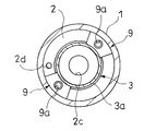
- FIG. 3 is a left side view of the actuator according to the embodiment.
- FIG. 4 is an XX sectional view of the actuator in one embodiment.
- the actuator A in one embodiment includes an aluminum alloy cylinder 1, a bottom portion 2 that closes one end of the cylinder 1, and a cylinder 1 that is inserted into the cylinder 1 and connected to the bottom portion 2.
- a cylindrical inner rod 3 that forms an annular gap S with the cylinder 1, a piston rod 4 that is cylindrical and that is closed at one end and slidably contacts the outer periphery of the inner rod 3, and a piston rod 4 And a piston 5 slidably contacting the inner periphery of the cylinder 1.
- the cylinder 1 is a cylinder made of an aluminum alloy, and one end that is the left end in FIG. 1 is closed by a bottom portion 2.
- the cylinder 1 and the bottom part 2 are integrally formed of an aluminum alloy.
- a hard anodized film 1a is formed on the inner periphery of the cylinder 1 to improve slidability and wear resistance.
- An aluminum alloy which is a base material of the cylinder 1 and the bottom portion 2 is an alloy containing copper, manganese, silicon, magnesium, zinc, nickel and the like in aluminum, and is superior in strength and the like as compared with pure aluminum.
- annular rod guide 6 that slides on the outer periphery of the piston rod 4 and guides the axial movement of the piston rod 4 relative to the cylinder 1 is provided on the inner periphery of the opening at the other end, which is the right end in FIG. It has been.
- the cylinder 1 is provided with a pressure introduction port 1b that communicates the inside of the cylinder 1 to the outside of the cylinder 1 at a position near the right end in FIG.
- the rod guide 6 is screwed to the inner periphery of the right end in FIG. 1 of the cylinder 1, and an annular seal member 7 is interposed between the cylinder 1 and the rod guide 6.
- the seal member 7 seals between the cylinder 1 and the rod guide 6.
- the rod guide 6 includes an annular seal member 19 on the inner periphery.
- the seal member 19 is in sliding contact with the outer periphery of the piston rod 4 to seal between the piston rod 4 and the rod guide 6.
- the bottom portion 2 includes an eye-shaped bracket 2a that allows the actuator A to be attached to the installation location at the left end in FIG. 1, and a recess 2b that opens in the axial direction from the right end in FIG.
- a pressure introduction port 2c that opens and communicates with the bottom of the recess 2b, and a through hole 2d that opens from a position at the right end of the bottom 2 in FIG. 1 and avoids the recess 2b and communicates outwardly in the cylinder 1 are provided. ing.
- the bottom portion 2 opens from a position avoiding the bracket 2a, extends in the axial direction of the actuator A, and opens at a position avoiding the recess 2b and the through hole 2d.
- Through holes 2e, 2e are provided.
- a cylindrical inner rod 3 is inserted into the recess 2 b of the bottom portion 2.
- An annular gap S is formed between the inner rod 3 and the cylinder 1.
- the right end of the bottom portion 2 in FIG. 1 and the outer peripheral side of the recess 2b faces the annular gap S, and the through hole 2d and the through holes 2e and 2e are communicated with the annular gap S.
- An annular seal member 8 is disposed between the bottom of the recess 2 b of the bottom portion 2 and the inner rod 3, and the bottom portion 2 and the inner rod 3 are sealed by the seal member 8.
- the pressure inlet 2c is open at the bottom of the recess 2b and is not blocked by the inner rod 3 and the seal member 8.
- An annular groove 3a formed over the entire circumference is provided on the outer circumference of the inner rod 3 in the vicinity of the left end in FIG.
- fan-shaped fixing brackets 9 are inserted into the annular groove 3a.
- the fixing fittings 9 and 9 are provided with screw holes 9a, respectively.
- the diameter of the through holes 2e and 2e is reduced from the middle when proceeding to the cylinder 1 side, and stepped portions 2f and 2f are provided in the middle.
- the inner rod 3 is drawn into the recess 2 b of the bottom portion 2, and the inner rod 3 is fixed to the bottom portion 2. Since the axial positions of the fixtures 9 and 9 can be adjusted by rotating the bolts 10 and 10, the load applied to the seal member 8 sandwiched between the inner rod 3 and the bottom of the bottom portion 2 can be controlled.
- the fixing brackets 9 may contact the bottom portion 2 with the inner rod 3 fixed to the bottom portion 2, but do not face the through hole 2d in the axial direction so as not to block the through hole 2d. Placed in position.
- a circular head cap 12 is screwed to the inner periphery of the inner rod 3 at the right end in FIG. 1 and a permanent magnet 11 is attached.
- a passage 12 a is provided in the head cap 12, and a passage 13 a is also provided in the holder 13 that holds the permanent magnet 11 and is attached to the inner periphery of the inner rod 3. Therefore, the inner rod 3 communicates with the outside of the inner rod 3 through the passages 12a and 13a.
- the piston rod 4 has a cylindrical shape, and a cap 14 having an eye-shaped bracket 14a that allows the actuator A to be attached to the installation location is attached to one end, which is the right end in FIG. Therefore, one end of the piston rod 4 which is the right end in FIG. 1 is closed by the cap 14.
- the piston rod 4 is slidably in contact with the outer periphery of the inner rod 3 and is movable in the axial direction with respect to the cylinder 1 and the inner rod 3.
- Annular seal members 15 and 16 are provided. Therefore, the inside of the piston rod 4 and the inner rod 3 forms a space that is expanded and contracted by the relative movement of the piston rod 4 and the inner rod 3 in the axial direction, and this space forms the extension side chamber R1.
- the piston rod 4 defines the extension side chamber R ⁇ b> 1 together with the inner rod 3.
- the extension side chamber R1 communicates with the pressure introduction port 2c, and the supply of the liquid to the extension side chamber R1 and the discharge of the liquid from the extension side chamber R1 are possible via the pressure introduction port 2c.
- the cap 14 holds a stroke sensor 17 having a sensor rod 17a that accommodates a magnetostrictive wire that detects the axial position of the permanent magnet 11.
- the sensor rod 17 a is inserted into the inner rod 3 through the inner circumference of the head cap 12 and the inner circumference of the permanent magnet 11.
- the stroke sensor 17 applies a current pulse to the magnetostrictive line in order to generate a magnetic field on the outer periphery of the magnetostrictive line, and then returns to a vibration pulse generated at a portion facing the permanent magnet 11 of the magnetostrictive line due to the Wiedemann effect.
- a signal is output according to the time.
- the stroke sensor 17 is installed to feed back the displacement detected by the stroke sensor 17 and control the expansion and contraction of the actuator A.
- the stroke sensor 17 can be abolished if unnecessary. Good.
- An annular piston 5 slidably contacting the inner periphery of the cylinder 1 is provided on the outer periphery of the left end of the piston rod 4 in FIG.
- An annular seal member 18 that is in sliding contact with the inner periphery of the cylinder 1 is provided on the outer periphery of the piston 5, and the space between the piston 5 and the cylinder 1 is sealed by the seal member 18.
- the piston 5 has an annular gap S between the cylinder 1 and the inner rod 3, a space between the cylinder 1 and the piston rod 4, a space between the cylinder 1 and the inner rod 3 and facing the bottom portion 2. It is divided into and.
- a pressure side chamber R ⁇ b> 2 is formed in the space between the cylinder 1 and the piston rod 4.
- the piston 5 partitions the pressure side chamber R2 between the cylinder 1 and the piston rod 4.
- the pressure side chamber R2 communicates with a pressure introduction port 1b provided in the cylinder 1, and can supply liquid to the pressure side chamber R2 and discharge liquid from the pressure side chamber R2 via the pressure introduction port 1b. Yes.
- the actuator A configured as described above supplies a liquid such as hydraulic oil to the expansion side chamber R1 and discharges the liquid from the compression side chamber R2, the liquid supplied to the expansion side chamber R1 pushes the piston rod 4 to the cylinder 1.
- the actuator A supplies a liquid such as hydraulic oil to the pressure side chamber R2 and discharges the liquid from the extension side chamber R1
- the liquid supplied to the pressure side chamber R2 pushes the piston 5 and moves the piston rod 4 into the cylinder 1. Invades and exhibits contraction.
- the actuator A configured as described above equalizes the pressure receiving area that receives the pressure of the expansion side chamber R1 and the pressure receiving area that receives the pressure of the compression side chamber R2. Therefore, if the pressure in the expansion side chamber R1 when the actuator A is extended and the pressure in the pressure side chamber R2 when the actuator A is contracted are the same, the actuator A has the same magnitude during the expansion operation and during the contraction operation. Now, the thrust is different only in the direction. That is, the actuator A functions as a double rod type linear cylinder. Since the space between the piston 5 and the bottom portion 2 is opened to the atmosphere through the through hole 2d through the annular gap S and is always at atmospheric pressure, the space does not function as an air spring. Therefore, the expansion / contraction operation of the actuator A is not hindered by the space, and the actuator A can extend and contract smoothly.
- the following is performed.
- the cylinder 1 whose one end is closed by the bottom portion 2 is immersed in an electrolyte such as sulfuric acid or oxalic acid, and the cylinder 1 is held by the anode connected to the positive electrode of the power source, and is separated from the cylinder 1 in the electrolyte.
- the cylinder 1 and the bottom part 2 are anodized (anodized), and a hard anodized film 1 a is formed on the inner peripheral surface of the cylinder 1. Note that the hard anodized film is formed on all but the contact point between the cylinder 1 and the anode of the bottom portion 2 by the above-described treatment.
- the cylinder 1 is immersed in the electrolytic solution, but the inside and outside of the cylinder 1 are communicated with each other through the through-hole 2d, so that the electrolytic solution can flow, and a good hard anode is formed on the inner peripheral surface of the cylinder 1.
- the oxide film 1a can be formed.
- the hard anodized film 1a is superior in slidability and wear resistance compared to an aluminum alloy that has not been anodized (anodized), and can reduce wear of the cylinder 1 due to sliding of the piston 5.
- a plasma field oxide film that forms a ceramic crystalline film having a fine structure on the surface of the cylinder 1 by underwater plasma in a state where the cylinder 1 is immersed in an electrolytic solution may be formed. Also in this case, the cylinder 1 is immersed in the electrolytic solution, but the inside and outside of the cylinder 1 communicate with each other through the through-hole 2d, so that the electrolytic solution can flow, so that a good film is formed on the inner peripheral surface of the cylinder 1. Can be formed. Since the plasma field oxide film is also excellent in slidability and wear resistance, the plasma field oxide film may be formed on the inner peripheral surface of the cylinder 1 by performing plasma electrolytic oxidation instead of the hard anodizing process.
- the electrolyte flows in the through hole 2d, so that a film is also formed on the inner periphery of the through hole 2d. Although it is formed, it may be scraped off if it is better not to have a film on the inner periphery of the through hole 2d.
- the actuator A of the present invention has a cylinder 1 made of an aluminum alloy, a bottom portion 2 that closes one end of the cylinder 1, and a cylindrical gap S inserted between the cylinder 1 and the cylinder 1.
- a piston 5 that slidably contacts the inner circumference of the cylinder 1 and divides the pressure side chamber R2 between the cylinder 1 and the piston rod 4, the bottom portion 2 has a through hole 2d that communicates with the annular gap S, and the cylinder 1 has an inner circumference.
- the film 1a is formed by surface treatment using an electrolytic solution.
- the electrolytic solution can flow inside and outside the cylinder 1 through the through-hole 2d, so that a good coating 1a can be formed, and slidability and wear resistance can be formed. Will improve.
- the actuator A of the present invention it is possible to form a favorable coating 1 a on the inner peripheral surface of the cylinder 1. Further, since the annular gap S excluding the pressure side chamber R2 is opened to the atmosphere by the through hole 2d, the actuator A can be expanded and contracted smoothly when the actuator A is driven.
- the through-hole 2d can be used for both the improvement of the fluidity of the electrolyte during the surface treatment of the cylinder 1 and the compensation of the smooth expansion / contraction operation during the driving.
Landscapes
- Engineering & Computer Science (AREA)
- General Engineering & Computer Science (AREA)
- Mechanical Engineering (AREA)
- Fluid Mechanics (AREA)
- Physics & Mathematics (AREA)
- Chemical & Material Sciences (AREA)
- Electrochemistry (AREA)
- Materials Engineering (AREA)
- Metallurgy (AREA)
- Organic Chemistry (AREA)
- Chemical Kinetics & Catalysis (AREA)
- Combustion & Propulsion (AREA)
- Actuator (AREA)
- Pistons, Piston Rings, And Cylinders (AREA)
Abstract
アクチュエータ(A)は、アルミニウム合金製のシリンダ(1)と、シリンダ(1)の一端を閉塞するボトム部(2)と、シリンダ(1)内に挿入されてシリンダ(1)との間に環状隙間(S)を形成する筒状のインナーロッド(3)と、筒状で一方の端部が閉塞されてインナーロッド(3)の外周に摺接してインナーロッド(3)とともに伸側室(R1)を区画するピストンロッド(4)と、ピストンロッド(4)に設けられてシリンダ(1)の内周に摺接してシリンダ(1)とピストンロッド(4)との間に圧側室(R2)を区画するピストン(5)とを備え、ボトム部(2)が環状隙間(S)に通じる通孔(2d)を有し、シリンダ(1)が内周に電解液を利用した表面処理で形成される皮膜(1a)を有している。
Description
本発明は、アクチュエータに関する。
航空機では、エルロン、ラダー、エレベータといった舵の駆動、ランディングギアの昇降などに油圧アクチュエータを利用している。このような油圧アクチュエータとしては、たとえば、シリンダとシリンダ内に摺動自在に挿入されるピストンとシリンダ内に挿入されるとともにピストンに連結されるピストンロッドとを備えている。そして、アクチュエータは、外部のポンプからシリンダ内の伸側室と圧側室の一方に圧油が供給されると伸縮作動を呈する。
また、航空機では、機体性能や燃費の向上には軽量化が要求されるため、航空機に利用されるアクチュエータにあっても同様に軽量化が要望される。そのため、従来のアクチュエータでは、シリンダの素材を強度が強く、重量が軽量なアルミニウム合金とするものがある。
この様なアクチュエータでは、たとえば、JP2009-103241Aに開示されているように、摺動性能や耐摩耗性の向上のために、アルミニウム合金製のシリンダの摺動面に表面処理を行って、摺動性や耐摩耗性に優れる皮膜を形成する場合がある。
しかしながら、前述のアクチュエータでは、シリンダの表面に皮膜を形成する際にシリンダを硫酸や蓚酸といった電解液に浸漬させる加工を採用する場合、シリンダの端部が閉塞されているために電解液の流動が悪く良好な皮膜を得られない可能性がある。
そこで、本発明は、シリンダの内周面に良好な皮膜の形成が可能なアクチュエータの提供を目的とする。
上記した目的を達成するため、アルミニウム合金製のシリンダと、シリンダの一端を閉塞するボトム部と、シリンダ内に挿入されてシリンダとの間に環状隙間を形成する筒状のインナーロッドと、筒状で一方の端部が閉塞されてインナーロッドの外周に摺接してインナーロッドとともに伸側室を区画するピストンロッドと、ピストンロッドに設けられてシリンダの内周に摺接してシリンダとピストンロッドとの間に圧側室を区画するピストンとを備え、ボトム部が環状隙間に通じる通孔を有し、シリンダが内周に電解液を利用した表面処理で形成される皮膜を有している。
以下、図に示した実施の形態に基づき、本発明を説明する。一実施の形態におけるアクチュエータAは、図1に示すように、アルミニウム合金製のシリンダ1と、シリンダ1の一端を閉塞するボトム部2と、シリンダ1内に挿入されるとともにボトム部2に連結されてシリンダ1との間に環状隙間Sを形成する筒状のインナーロッド3と、筒状であって一方の端部が閉塞されてインナーロッド3の外周に摺接するピストンロッド4と、ピストンロッド4に設けられてシリンダ1の内周に摺接するピストン5とを備えている。
以下、アクチュエータAの各部について詳細に説明する。シリンダ1は、図1に示すように、アルミニウム合金製の筒体であり、図1中左端である一端がボトム部2によって閉塞されている。本例では、シリンダ1とボトム部2とは、アルミニウム合金で一体に成形されている。また、シリンダ1の内周には、硬質陽極酸化皮膜1aが形成されており、摺動性と耐摩耗性の向上が図られている。シリンダ1とボトム部2の母材であるアルミニウム合金は、アルミニウムに銅、マンガン、ケイ素、マグネシウム、亜鉛、ニッケル等を含んだ合金であり、純アルミニウムに比較して強度面等で優れている。
また、シリンダ1の図1中右端である他端の開口部内周には、ピストンロッド4の外周に摺接してピストンロッド4のシリンダ1に対する軸方向の移動を案内する環状のロッドガイド6が設けられている。なお、シリンダ1は、図1中右端の近傍であってロッドガイド6に干渉しない位置にシリンダ1内をシリンダ1外へ連通する圧力導入口1bを備えている。
ロッドガイド6は、シリンダ1の図1中右端内周に螺合されており、シリンダ1とロッドガイド6との間には環状のシール部材7が介装されている。このシール部材7によって、シリンダ1とロッドガイド6との間がシールされている。また、ロッドガイド6は、内周に環状のシール部材19を備えている。シール部材19は、ピストンロッド4の外周に摺接してピストンロッド4とロッドガイド6との間をシールしている。
また、ボトム部2は、図1中左端にアクチュエータAを設置個所へ取付可能とするアイ型のブラケット2aを備える他、図1中右端から軸方向に向けて開口する凹部2bと、側方から開口して凹部2bの底へ通じる圧力導入口2cと、ボトム部2の図1中右端であって凹部2bを避けた位置から開口してシリンダ1内を外方へ連通する通孔2dを備えている。
また、ボトム部2は、図2および図3に示すように、ブラケット2aを避けた位置から開口してアクチュエータAの軸方向へ伸びて凹部2bと通孔2dを避けた位置に開口する二つの貫通孔2e,2eを備える。
ボトム部2の凹部2b内には、筒状のインナーロッド3が挿入されている。そして、インナーロッド3とシリンダ1との間には、環状隙間Sが形成されている。ボトム部2の図1中右端であって凹部2bの外周側は、環状隙間Sに対面しており、通孔2dおよび貫通孔2e,2eが環状隙間Sに連通されている。
ボトム部2の凹部2bにおける底とインナーロッド3との間には、環状のシール部材8が配置されており、ボトム部2とインナーロッド3との間が前記シール部材8によってシールされている。なお、圧力導入口2cは、凹部2bの底に開口しているので、インナーロッド3およびシール部材8によって閉塞されない。
インナーロッド3の図1中左端の近傍の外周には、全周に亘って形成される環状溝3aが設けられている。環状溝3aには、図2および図4に示すように、扇型の固定金具9,9が挿入されている。固定金具9,9には、それぞれ螺子孔9aが設けられている。また、貫通孔2e,2eは、シリンダ1側へ進むと途中から径が小さくなっており、途中に段部2f,2fを備えている。そして、貫通孔2e,2e内にボルト10,10を挿入して螺子孔9a,9aに捩じ込むと、ボルト10,10の頭が段部2f,2fに当接して固定金具9,9を介してインナーロッド3がボトム部2の凹部2b内に引き込まれてインナーロッド3がボトム部2に固定される。そして、ボルト10,10の回転操作によって固定金具9,9の軸方向位置を調整できるので、インナーロッド3とボトム部2の底とで挟持されるシール部材8へ与える荷重をコントロールできる。なお、固定金具9,9は、インナーロッド3をボトム部2に固定した状態でボトム部2に接触してもよいが、通孔2dを塞がないように通孔2dに軸方向で対向しない位置に配置される。なお、インナーロッド3のボトム部2への締結については、前述した構造によらず、螺子締結や圧入、その他の締結方法を採用してもよい。
インナーロッド3の図1中右端の内周には、環状のヘッドキャップ12が螺合されるともに、永久磁石11が取り付けられている。ヘッドキャップ12には通路12aが設けられており、永久磁石11を保持してインナーロッド3の内周に装着されるホルダ13にも通路13aが設けられている。よって、インナーロッド3内は、通路12a,13aを介してインナーロッド3の外方へと通じている。
ピストンロッド4は、筒状であって、図1中右端である一方の端部にアクチュエータAを設置個所へ取付可能とするアイ型のブラケット14aを備えるキャップ14が装着されている。よって、ピストンロッド4の図1中右端である一方の端部はキャップ14によって閉塞されている。また、ピストンロッド4は、インナーロッド3の外周に摺接してシリンダ1およびインナーロッド3に対して軸方向へ移動可能であって、図1中左端内周には、インナーロッド3の外周に摺接する環状のシール部材15,16を備えている。よって、ピストンロッド4とインナーロッド3の内部は、ピストンロッド4とインナーロッド3の軸方向の相対移動によって拡縮される空間を形成しており、この空間で伸側室R1を形成している。つまり、ピストンロッド4は、インナーロッド3とともに伸側室R1を区画している。伸側室R1は、圧力導入口2cに通じていて、圧力導入口2cを介して伸側室R1への液体の供給と伸側室R1からの液体の排出が可能となっている。
キャップ14は、永久磁石11の軸方向位置を検知する磁歪線を収容するセンサロッド17aを備えたストロークセンサ17を保持している。センサロッド17aは、前記したヘッドキャップ12の内周および永久磁石11の内周を通してインナーロッド3内に挿入されている。そして、ストロークセンサ17は、磁歪線の外周に磁界を発生させるために磁歪線に電流パルスを与えてから、Wiedemann効果によって磁歪線の永久磁石11に対向する部位に生じる振動パルスが帰って来るまでの時間に応じた信号を出力する。これにより、ストロークセンサ17が出力する信号からインナーロッド3に対するピストンロッド4の軸方向の変位を検知できる。なお、本実施の形態では、ストロークセンサ17で検知した変位をフィードバックしてアクチュエータAの伸縮を制御するためにストロークセンサ17を設置しているが、不要であればストロークセンサ17を廃止してもよい。
ピストンロッド4の図1中左端の外周には、シリンダ1の内周に摺接する環状のピストン5が設けられている。ピストン5の外周には、シリンダ1の内周に摺接する環状のシール部材18が設けられており、ピストン5とシリンダ1との間がシール部材18によってシールされている。ピストン5は、シリンダ1とインナーロッド3との間の環状隙間Sを、シリンダ1とピストンロッド4との間の空間とシリンダ1とインナーロッド3との間であってボトム部2に面する空間とに仕切っている。そして、シリンダ1とピストンロッド4との間の空間で圧側室R2を形成している。このように、ピストン5は、シリンダ1とピストンロッド4との間に圧側室R2を区画している。この圧側室R2は、シリンダ1に設けられた圧力導入口1bに通じていて、圧力導入口1bを介して圧側室R2への液体の供給と圧側室R2からの液体の排出が可能となっている。
そして、ピストンロッド4をシリンダ1に対して図1中左方へ押す方向に圧側室R2の圧力を受ける受圧面積は、シリンダ1の内周の断面積からピストンロッド4の外周の断面積を差し引いた面積となる。ピストンロッド4をシリンダ1に対して図1中右方へ押す方向に伸側室R1の圧力を受ける受圧面積は、インナーロッド3の外周の断面積となる。本実施の形態では、伸側室R1の圧力を受ける受圧面積と圧側室R2の圧力を受ける受圧面積を等しくしている。
以上のように構成されたアクチュエータAは、伸側室R1へ作動油等の液体を供給し、圧側室R2から液体を排出させる場合、伸側室R1へ供給された液体がピストンロッド4を押してシリンダ1内から退出させて伸長作動を呈する。反対に、アクチュエータAは、圧側室R2へ作動油等の液体を供給し、伸側室R1から液体を排出させる場合、圧側室R2へ供給された液体がピストン5を押してシリンダ1内へピストンロッド4を侵入させて収縮作動を呈する。
そして、このように構成されたアクチュエータAは、前述したように、伸側室R1の圧力を受ける受圧面積と圧側室R2の圧力を受ける受圧面積とを等しくしている。よって、アクチュエータAを伸長作動させる際の伸側室R1の圧力と、アクチュエータAを収縮作動させる際の圧側室R2の圧力を同じにすれば、アクチュエータAは伸長作動時と収縮作動時とで同じ大きさで向きだけが異なる推力を発揮する。つまり、このアクチュエータAは、両ロッド型の直動シリンダとして機能する。そして、通孔2dが環状隙間Sに通じてピストン5とボトム部2との間の空間が大気開放されて常に大気圧とされるから、前記空間がエアばねとして機能することはない。よって、前記空間によってアクチュエータAの伸縮作動が阻害されず、アクチュエータAはスムーズに伸縮できる。
そして、このアクチュエータAにおけるシリンダ1の内周に硬質陽極酸化皮膜を形成するには、次のようにする。ボトム部2によって一端が閉塞されたシリンダ1を硫酸あるは蓚酸といった電解液中に浸漬させ、電源のプラスの電極に接続された陽極でシリンダ1を保持させ、電解液中でシリンダ1から離間した陰極を電源のマイナスの電極に接続して通電する。すると、シリンダ1およびボトム部2が陽極酸化処理(アルマイト処理)されて、シリンダ1の内周面に硬質陽極酸化皮膜1aが形成される。なお、硬質陽極酸化皮膜は、前記処理によってシリンダ1とボトム部2の陽極との接点以外の全てに形成される。
この陽極酸化処理は、電解液中にシリンダ1を浸漬させるが、通孔2dによってシリンダ1の内外が連通されるので、電解液の流動が可能となり、シリンダ1の内周面に良好な硬質陽極酸化皮膜1aを形成できる。
硬質陽極酸化皮膜1aは、陽極酸化処理(アルマイト処理)をしていないアルミニウム合金に比べて、摺動性と耐摩耗性に優れており、ピストン5の摺動によるシリンダ1の摩耗を軽減できる。
また、シリンダ1を電解液中に浸漬させた状態で水中プラズマによりシリンダ1の表面に微細構造を有するセラミックス結晶性皮膜を形成するプラズマ電界酸化皮膜を形成してもよい。この場合も、電解液中にシリンダ1を浸漬させるが、通孔2dによってシリンダ1の内外が連通されるので、電解液の流動が可能となるので、シリンダ1の内周面に良好な皮膜を形成できる。プラズマ電界酸化皮膜も摺動性と耐摩耗性に優れるので、硬質陽極酸化処理に代えてプラズマ電解酸化処理を施してシリンダ1の内周面にプラズマ電界酸化皮膜を形成してもよい。
なお、シリンダ1の内周面に硬質陽極酸化皮膜1aやプラズマ電界酸化皮膜といった皮膜を形成する際には電解液中が通孔2d内を流動するので、通孔2dの内周にも皮膜が形成されるが、通孔2dの内周に皮膜がない方が良い場合には削り取ってもよい。
以上、本発明のアクチュエータAは、アルミニウム合金製のシリンダ1と、シリンダ1の一端を閉塞するボトム部2と、シリンダ1内に挿入されてシリンダ1との間に環状隙間Sを形成する筒状のインナーロッド3と、筒状で一方の端部が閉塞されてインナーロッド3の外周に摺接してインナーロッド3とともに伸側室R1を区画するピストンロッド4と、ピストンロッド4に設けられてシリンダ1の内周に摺接してシリンダ1とピストンロッド4との間に圧側室R2を区画するピストン5とを備え、ボトム部2が環状隙間Sに通じる通孔2dを有し、シリンダ1が内周に電解液を利用した表面処理で形成される皮膜1aを有している。このように構成されたアクチュエータAでは、シリンダ1の表面処理を行う際に通孔2dにより電解液がシリンダ1の内外を流動できるので、良好な皮膜1aを形成でき、摺動性と耐摩耗性が向上する。このように、本発明のアクチュエータAよれば、シリンダ1の内周面に良好な皮膜1aの形成が可能となる。そして、さらに、通孔2dによって圧側室R2を除く環状隙間Sが大気開放されるので、アクチュエータAを駆動させる際にはアクチュエータAはスムーズに伸縮できる。このように、本発明のアクチュエータAでは、通孔2dをシリンダ1の表面処理時における電解液の流動性の向上と駆動時におけるスムーズな伸縮作動の補償という両面で利用できるのである。
以上、本発明の好ましい実施の形態を詳細に説明したが、特許請求の範囲から逸脱しない限り、改造、変形、及び変更が可能である。
本願は、2018年1月31日に日本国特許庁に出願された特願2018-014668に基づく優先権を主張し、この出願の全ての内容は参照により本明細書に組み込まれる。
Claims (2)
- アクチュエータであって、
アルミニウム合金製のシリンダと、
前記シリンダの一端を閉塞するボトム部と、
前記シリンダ内に挿入されるとともに前記ボトム部に連結されて前記シリンダとの間に環状隙間を形成する筒状のインナーロッドと、
筒状で一方の端部が閉塞されて前記インナーロッドの外周に摺接して前記シリンダおよび前記インナーロッドに対して軸方向へ移動可能であって、前記インナーロッドとともに伸側室を区画するピストンロッドと、
前記ピストンロッドに設けられて前記シリンダの内周に摺接して前記シリンダと前記ピストンロッドとの間に圧側室を区画するピストンとを備え、
前記ボトム部は、前記環状隙間に通じる通孔を有し、
前記シリンダは、内周に電解液を利用した表面処理で形成される皮膜を有する
アクチュエータ。 - 請求項1に記載のアクチュエータであって、
前記皮膜は、硬質陽極酸化皮膜或いはプラズマ電界酸化皮膜である
アクチュエータ。
Priority Applications (1)
| Application Number | Priority Date | Filing Date | Title |
|---|---|---|---|
| US16/649,034 US20200217333A1 (en) | 2018-01-31 | 2018-08-14 | Actuator |
Applications Claiming Priority (2)
| Application Number | Priority Date | Filing Date | Title |
|---|---|---|---|
| JP2018-014668 | 2018-01-31 | ||
| JP2018014668A JP6963517B2 (ja) | 2018-01-31 | 2018-01-31 | アクチュエータ |
Publications (1)
| Publication Number | Publication Date |
|---|---|
| WO2019150618A1 true WO2019150618A1 (ja) | 2019-08-08 |
Family
ID=67478691
Family Applications (1)
| Application Number | Title | Priority Date | Filing Date |
|---|---|---|---|
| PCT/JP2018/030277 Ceased WO2019150618A1 (ja) | 2018-01-31 | 2018-08-14 | アクチュエータ |
Country Status (3)
| Country | Link |
|---|---|
| US (1) | US20200217333A1 (ja) |
| JP (1) | JP6963517B2 (ja) |
| WO (1) | WO2019150618A1 (ja) |
Families Citing this family (1)
| Publication number | Priority date | Publication date | Assignee | Title |
|---|---|---|---|---|
| KR20240003265A (ko) | 2022-06-30 | 2024-01-08 | 현대자동차주식회사 | 차고 조절 장치 |
Citations (8)
| Publication number | Priority date | Publication date | Assignee | Title |
|---|---|---|---|---|
| US4608912A (en) * | 1984-11-05 | 1986-09-02 | Allied Corporation | Linear hydraulic actuator having ballistic tolerant |
| JPH0496603U (ja) * | 1991-01-31 | 1992-08-21 | ||
| JPH11291017A (ja) * | 1998-04-13 | 1999-10-26 | Matsuo Kogyo Kk | アルミニウム鋳造品及びその製造方法 |
| JP2002227807A (ja) * | 2001-02-02 | 2002-08-14 | Nissei Koki Kk | エアシリンダ |
| JP2004011855A (ja) * | 2002-06-10 | 2004-01-15 | Smc Corp | 速度制御機構付シリンダ |
| JP2009103241A (ja) | 2007-10-24 | 2009-05-14 | Ihi Corp | 耐摩耗補強方法及び摺動構造体 |
| JP2014051721A (ja) * | 2012-09-10 | 2014-03-20 | Denso Corp | アルミニウムの陽極酸化方法 |
| JP2018014668A (ja) | 2016-07-22 | 2018-01-25 | Kddi株式会社 | 通信装置、通信方法、及びコンピュータプログラム |
Family Cites Families (3)
| Publication number | Priority date | Publication date | Assignee | Title |
|---|---|---|---|---|
| US4867044A (en) * | 1984-11-26 | 1989-09-19 | The United States Of America As Represented By The Secretary Of The Navy | Jam resistant fluid power actuator for ballistic-damage tolerant redundant cylinder assemblies |
| JP2004277812A (ja) * | 2003-03-14 | 2004-10-07 | Shinsuke Mochizuki | Al系複合部材とその製造方法 |
| JP2018123847A (ja) * | 2017-01-30 | 2018-08-09 | Kyb株式会社 | 緩衝器および摺動部材の製造方法 |
-
2018
- 2018-01-31 JP JP2018014668A patent/JP6963517B2/ja not_active Expired - Fee Related
- 2018-08-14 WO PCT/JP2018/030277 patent/WO2019150618A1/ja not_active Ceased
- 2018-08-14 US US16/649,034 patent/US20200217333A1/en not_active Abandoned
Patent Citations (8)
| Publication number | Priority date | Publication date | Assignee | Title |
|---|---|---|---|---|
| US4608912A (en) * | 1984-11-05 | 1986-09-02 | Allied Corporation | Linear hydraulic actuator having ballistic tolerant |
| JPH0496603U (ja) * | 1991-01-31 | 1992-08-21 | ||
| JPH11291017A (ja) * | 1998-04-13 | 1999-10-26 | Matsuo Kogyo Kk | アルミニウム鋳造品及びその製造方法 |
| JP2002227807A (ja) * | 2001-02-02 | 2002-08-14 | Nissei Koki Kk | エアシリンダ |
| JP2004011855A (ja) * | 2002-06-10 | 2004-01-15 | Smc Corp | 速度制御機構付シリンダ |
| JP2009103241A (ja) | 2007-10-24 | 2009-05-14 | Ihi Corp | 耐摩耗補強方法及び摺動構造体 |
| JP2014051721A (ja) * | 2012-09-10 | 2014-03-20 | Denso Corp | アルミニウムの陽極酸化方法 |
| JP2018014668A (ja) | 2016-07-22 | 2018-01-25 | Kddi株式会社 | 通信装置、通信方法、及びコンピュータプログラム |
Also Published As
| Publication number | Publication date |
|---|---|
| JP2019132338A (ja) | 2019-08-08 |
| JP6963517B2 (ja) | 2021-11-10 |
| US20200217333A1 (en) | 2020-07-09 |
Similar Documents
| Publication | Publication Date | Title |
|---|---|---|
| JP2007071363A (ja) | シリンダ装置 | |
| CN109563857B (zh) | 流体压力装置 | |
| JP2015182710A (ja) | トリム・チルト装置および船舶推進機 | |
| EP3575628A1 (en) | Shock absorber and method for manufacturing sliding member | |
| WO2019150618A1 (ja) | アクチュエータ | |
| JP4891915B2 (ja) | 単一ピストンまたは2重ピストンを使用する低衝撃スポット溶接シリンダ | |
| JP6148086B2 (ja) | バルブ装置及び塗工装置 | |
| CN109058356B (zh) | 一种单筒双腔往复式阻尼器 | |
| JP4895342B2 (ja) | 流体圧シリンダ | |
| EP2687724B1 (en) | Piston pump | |
| SU1600640A3 (ru) | Дифференциальный гидравлический силовой цилиндр дл масл нопневматического привода электрического выключател | |
| JP2710724B2 (ja) | 角形偏平シリンダ | |
| US20210010560A1 (en) | Damper device | |
| JP6933985B2 (ja) | 液圧機器 | |
| WO2013099642A1 (ja) | 流体圧シリンダ | |
| JP5412053B2 (ja) | 空気圧シリンダ | |
| CN220302300U (zh) | 一种用在空气悬架上的空气压缩设备缸体 | |
| CN107893794B (zh) | 等速油缸 | |
| CN117307553B (zh) | 液压油缸和作业机械 | |
| CN115419628B (zh) | 一种旁通液压油缸 | |
| JP2006151201A (ja) | 作動液リザーバおよび液圧制御ユニット | |
| CN221974084U (zh) | 一种自适应强制位移的恒力导向机构 | |
| CN110725889A (zh) | 一种收缩助力阻尼器 | |
| US20250019058A1 (en) | Outboard motor and marine vessel | |
| JP2010164066A (ja) | 流体圧シリンダ |
Legal Events
| Date | Code | Title | Description |
|---|---|---|---|
| 121 | Ep: the epo has been informed by wipo that ep was designated in this application |
Ref document number: 18903245 Country of ref document: EP Kind code of ref document: A1 |
|
| NENP | Non-entry into the national phase |
Ref country code: DE |
|
| ENP | Entry into the national phase |
Ref document number: 2018903245 Country of ref document: EP Effective date: 20200831 |
|
| 122 | Ep: pct application non-entry in european phase |
Ref document number: 18903245 Country of ref document: EP Kind code of ref document: A1 |