WO2019146528A1 - Goutteur et tube d'irrigation goutte à goutte - Google Patents
Goutteur et tube d'irrigation goutte à goutte Download PDFInfo
- Publication number
- WO2019146528A1 WO2019146528A1 PCT/JP2019/001521 JP2019001521W WO2019146528A1 WO 2019146528 A1 WO2019146528 A1 WO 2019146528A1 JP 2019001521 W JP2019001521 W JP 2019001521W WO 2019146528 A1 WO2019146528 A1 WO 2019146528A1
- Authority
- WO
- WIPO (PCT)
- Prior art keywords
- tube
- emitter
- pedestal
- pressure
- irrigation liquid
- Prior art date
Links
- 230000002262 irrigation Effects 0.000 title claims abstract description 96
- 238000003973 irrigation Methods 0.000 title claims abstract description 96
- 239000007788 liquid Substances 0.000 claims abstract description 75
- XLYOFNOQVPJJNP-UHFFFAOYSA-N water Substances O XLYOFNOQVPJJNP-UHFFFAOYSA-N 0.000 claims abstract description 39
- 238000004891 communication Methods 0.000 claims abstract description 27
- NJPPVKZQTLUDBO-UHFFFAOYSA-N novaluron Chemical compound C1=C(Cl)C(OC(F)(F)C(OC(F)(F)F)F)=CC=C1NC(=O)NC(=O)C1=C(F)C=CC=C1F NJPPVKZQTLUDBO-UHFFFAOYSA-N 0.000 claims description 113
- 238000003860 storage Methods 0.000 claims description 7
- 238000007599 discharging Methods 0.000 claims description 5
- 230000007423 decrease Effects 0.000 claims description 2
- 238000013459 approach Methods 0.000 claims 1
- 230000004308 accommodation Effects 0.000 abstract description 8
- 230000006837 decompression Effects 0.000 description 19
- 238000000034 method Methods 0.000 description 19
- 238000004519 manufacturing process Methods 0.000 description 17
- 239000000463 material Substances 0.000 description 11
- 238000010586 diagram Methods 0.000 description 10
- 238000003466 welding Methods 0.000 description 10
- 238000012986 modification Methods 0.000 description 8
- 230000004048 modification Effects 0.000 description 8
- 229920005989 resin Polymers 0.000 description 7
- 239000011347 resin Substances 0.000 description 7
- 238000011144 upstream manufacturing Methods 0.000 description 5
- 239000012528 membrane Substances 0.000 description 4
- 230000000694 effects Effects 0.000 description 3
- 239000012530 fluid Substances 0.000 description 3
- 238000001746 injection moulding Methods 0.000 description 3
- 239000004698 Polyethylene Substances 0.000 description 2
- 239000000470 constituent Substances 0.000 description 2
- 229920001971 elastomer Polymers 0.000 description 2
- 239000003337 fertilizer Substances 0.000 description 2
- 238000007667 floating Methods 0.000 description 2
- 238000005304 joining Methods 0.000 description 2
- 239000000203 mixture Substances 0.000 description 2
- -1 polyethylene Polymers 0.000 description 2
- 229920000573 polyethylene Polymers 0.000 description 2
- 239000002689 soil Substances 0.000 description 2
- 239000000853 adhesive Substances 0.000 description 1
- 230000001070 adhesive effect Effects 0.000 description 1
- 238000012364 cultivation method Methods 0.000 description 1
- 238000011161 development Methods 0.000 description 1
- 239000000806 elastomer Substances 0.000 description 1
- 230000007774 longterm Effects 0.000 description 1
- 230000000149 penetrating effect Effects 0.000 description 1
- 230000002093 peripheral effect Effects 0.000 description 1
- 239000000575 pesticide Substances 0.000 description 1
- 229920001296 polysiloxane Polymers 0.000 description 1
- 238000003825 pressing Methods 0.000 description 1
- 230000001105 regulatory effect Effects 0.000 description 1
- 239000005060 rubber Substances 0.000 description 1
- 238000007789 sealing Methods 0.000 description 1
- 239000000126 substance Substances 0.000 description 1
- 238000012360 testing method Methods 0.000 description 1
Images


Classifications
-
- A—HUMAN NECESSITIES
- A01—AGRICULTURE; FORESTRY; ANIMAL HUSBANDRY; HUNTING; TRAPPING; FISHING
- A01G—HORTICULTURE; CULTIVATION OF VEGETABLES, FLOWERS, RICE, FRUIT, VINES, HOPS OR SEAWEED; FORESTRY; WATERING
- A01G25/00—Watering gardens, fields, sports grounds or the like
- A01G25/02—Watering arrangements located above the soil which make use of perforated pipe-lines or pipe-lines with dispensing fittings, e.g. for drip irrigation
- A01G25/023—Dispensing fittings for drip irrigation, e.g. drippers
-
- A—HUMAN NECESSITIES
- A01—AGRICULTURE; FORESTRY; ANIMAL HUSBANDRY; HUNTING; TRAPPING; FISHING
- A01G—HORTICULTURE; CULTIVATION OF VEGETABLES, FLOWERS, RICE, FRUIT, VINES, HOPS OR SEAWEED; FORESTRY; WATERING
- A01G25/00—Watering gardens, fields, sports grounds or the like
- A01G25/02—Watering arrangements located above the soil which make use of perforated pipe-lines or pipe-lines with dispensing fittings, e.g. for drip irrigation
-
- A—HUMAN NECESSITIES
- A01—AGRICULTURE; FORESTRY; ANIMAL HUSBANDRY; HUNTING; TRAPPING; FISHING
- A01G—HORTICULTURE; CULTIVATION OF VEGETABLES, FLOWERS, RICE, FRUIT, VINES, HOPS OR SEAWEED; FORESTRY; WATERING
- A01G25/00—Watering gardens, fields, sports grounds or the like
- A01G25/06—Watering arrangements making use of perforated pipe-lines located in the soil
-
- A—HUMAN NECESSITIES
- A01—AGRICULTURE; FORESTRY; ANIMAL HUSBANDRY; HUNTING; TRAPPING; FISHING
- A01G—HORTICULTURE; CULTIVATION OF VEGETABLES, FLOWERS, RICE, FRUIT, VINES, HOPS OR SEAWEED; FORESTRY; WATERING
- A01G27/00—Self-acting watering devices, e.g. for flower-pots
-
- A—HUMAN NECESSITIES
- A01—AGRICULTURE; FORESTRY; ANIMAL HUSBANDRY; HUNTING; TRAPPING; FISHING
- A01G—HORTICULTURE; CULTIVATION OF VEGETABLES, FLOWERS, RICE, FRUIT, VINES, HOPS OR SEAWEED; FORESTRY; WATERING
- A01G13/00—Protecting plants
- A01G13/02—Protective coverings for plants; Coverings for the ground; Devices for laying-out or removing coverings
- A01G13/0256—Ground coverings
- A01G13/0268—Mats or sheets, e.g. nets or fabrics
- A01G13/0275—Films
-
- A—HUMAN NECESSITIES
- A01—AGRICULTURE; FORESTRY; ANIMAL HUSBANDRY; HUNTING; TRAPPING; FISHING
- A01G—HORTICULTURE; CULTIVATION OF VEGETABLES, FLOWERS, RICE, FRUIT, VINES, HOPS OR SEAWEED; FORESTRY; WATERING
- A01G25/00—Watering gardens, fields, sports grounds or the like
- A01G2025/006—Tubular drip irrigation dispensers mounted coaxially within water feeding tubes
-
- Y—GENERAL TAGGING OF NEW TECHNOLOGICAL DEVELOPMENTS; GENERAL TAGGING OF CROSS-SECTIONAL TECHNOLOGIES SPANNING OVER SEVERAL SECTIONS OF THE IPC; TECHNICAL SUBJECTS COVERED BY FORMER USPC CROSS-REFERENCE ART COLLECTIONS [XRACs] AND DIGESTS
- Y02—TECHNOLOGIES OR APPLICATIONS FOR MITIGATION OR ADAPTATION AGAINST CLIMATE CHANGE
- Y02A—TECHNOLOGIES FOR ADAPTATION TO CLIMATE CHANGE
- Y02A40/00—Adaptation technologies in agriculture, forestry, livestock or agroalimentary production
- Y02A40/10—Adaptation technologies in agriculture, forestry, livestock or agroalimentary production in agriculture
- Y02A40/22—Improving land use; Improving water use or availability; Controlling erosion
Definitions
- the present invention relates to an emitter and a drip irrigation tube having the emitter.
- the drip irrigation method is known as one of the plant cultivation methods.
- the drip irrigation method is a method of disposing a drip irrigation tube on the soil where plants are planted and dripping irrigation fluid such as water or liquid fertilizer from the drip irrigation tube onto the soil.
- irrigation fluid such as water or liquid fertilizer
- the drip irrigation tube is joined to a tube having a plurality of through holes through which the irrigation liquid is discharged, and the inner wall surface of the tube, and a plurality of emitters for discharging the irrigation liquid from each through hole (“ (Also referred to as “Dripper”) (see, for example, Patent Document 1).
- Patent Document 1 describes an emitter including a body and a flap movable relative to the body about a hinge.
- the flap is formed of the same, preferably identical, material as the body.
- the flap also has a membrane (diaphragm) disposed in the frame.
- the recess of the body is covered by the membrane of the flap rotated about the hinge.
- the recess is formed in the body with a rim provided on the frame housing as a peripheral portion.
- the pressure regulating chamber is formed by pressing the membrane of the flap against the rim.
- the flow rate of liquid out of the pressure adjustment chamber is adjusted by the membrane flexing elastically due to pressure fluctuations.
- the flap and the main body are integrally formed with the flap open. Then, the concave portion formed in the main body is covered by the film of the flap, thereby constituting a pressure control chamber for adjusting the flow rate of the liquid discharged from the emitter. Therefore, in order to put the emitter into operation, several steps are required, such as rotating the flap around the hinge, engaging the rotated flap with the main body by adhesion with chemicals or welding with heat, etc. Become. Since such a plurality of processes increase the manufacturing cost of the emitter, it is required to reduce the manufacturing cost. In particular, since the process of engaging the flap with the main body by adhesion, welding or the like greatly increases the manufacturing cost, there is a demand for an emitter which does not require adhesion, welding or the like in the manufacturing process.
- An object of the present invention is to provide an emitter and a drip irrigation tube capable of reducing the manufacturing cost.
- the emitter according to the present invention is joined to a position on the inner wall surface of a tube through which irrigation liquid flows, which corresponds to a discharge port communicating the inside and the outside of the tube, and the irrigation liquid in the tube is quantified from the discharge port.
- the pressure reducing flow passage portion for forming a pressure reducing flow passage flowing while reducing pressure, and the pressure reducing flow passage portion are in communication, and in order to adjust the flow rate of the irrigation liquid according to the pressure of the irrigation liquid in the tube
- the drip irrigation tube according to the present invention comprises a tube having a discharge port for discharging an irrigation liquid, and an emitter according to the present invention joined at a position corresponding to the discharge port on the inner wall surface of the tube. .
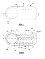
- FIG. 1 is a cross-sectional view (including a cross-sectional view of an emitter taken along line AA shown in FIG. 2A) of a drip irrigation tube according to Embodiment 1 of the present invention.
- 2A and 2B are diagrams showing the configuration of the emitter according to the first embodiment of the present invention.
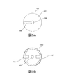
- FIGS. 3A to 3D are views showing the configuration of a pedestal according to Embodiment 1 of the present invention, and
- FIG. 3E is a view showing a modification of the configuration of the pedestal.
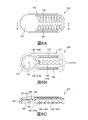
- FIG. 4A and FIG. 4B are diagrams showing a modification of the configuration of the emitter according to the first embodiment of the present invention.
- FIGS. 5B are diagrams showing modifications of the configuration of the pedestal according to Embodiment 1 of the present invention.
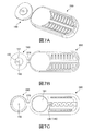
- 6A to 6C are diagrams showing the configuration of an emitter according to the second embodiment of the present invention.
- FIGS. 7A to 7C are diagrams showing the configuration of an emitter according to Embodiment 2 in the process of being manufactured.
- FIG. 1 is a cross-sectional view in a direction along the axis of drip irrigation tube 100 according to the first embodiment. As shown in FIG. 1, the drip irrigation tube 100 has a tube 110 and an emitter 120.
- the tube 110 is a tube for flowing irrigation liquid.
- irrigation liquids include water, liquid fertilizers, pesticides and mixtures thereof.
- the direction in which the irrigation liquid flows in the tube 110 is not particularly limited.
- the material of the tube 110 is not particularly limited. In the present embodiment, the material of the tube 110 is polyethylene.
- a plurality of discharge ports 111 for discharging the irrigation liquid at predetermined intervals (for example, 200 mm or more and 500 mm or less) in the axial direction of the tube 110 are formed.
- the diameter of the opening of the discharge port 111 is not particularly limited as long as the irrigation liquid can be discharged. In the present embodiment, the diameter of the opening of the discharge port 111 is 1.5 mm.
- the emitters 120 are respectively joined to the positions corresponding to the discharge ports 111 of the inner wall surface 112.
- the cross-sectional shape and cross-sectional area perpendicular to the axial direction of the tube 110 are not particularly limited as long as the emitter 120 can be disposed inside the tube 110.
- the drip irrigation tube 100 is manufactured by joining the back surface 121 of the emitter 120 to the inner wall surface 112.
- the method of bonding the tube 110 and the emitter 120 is not particularly limited. Examples of the method of bonding the tube 110 and the emitter 120 include welding of the resin material that constitutes the tube 110 or the emitter 120, adhesion with an adhesive, and the like.
- the discharge port 111 is formed after bonding the tube 110 and the emitter 120, but may be formed before bonding.
- FIG. 2A and 2B are diagrams showing the configuration of the emitter 120 according to the first embodiment.
- FIG. 2A is a plan view of the emitter 120
- FIG. 2B is a bottom view of the emitter 120.
- the emitter 120 (hereinafter also referred to as an “emitter main body”) with the pedestal 190 removed is shown.
- the emitter 120 is joined to the inner wall surface 112 of the tube 110 so as to cover the discharge port 111.
- the shape of the emitter 120 is not particularly limited as long as it can be in close contact with the inner wall surface 112 and cover the discharge port 111.
- the shape of the back surface joined to the inner wall surface 112 in the cross section of the emitter 120 perpendicular to the axial direction of the tube 110 has a substantially arc shape convex toward the inner wall surface 112 along the inner wall surface 112. It is.
- the plan view shape of the emitter 120 is a substantially rectangular shape whose four corners are R-chamfered as shown in FIG. 2A.
- the length in the long side direction of the emitter 120 is 19 mm
- the length in the short side direction is 8 mm
- the height is 2.7 mm.
- the size of the emitter 120 is not particularly limited, and may be appropriately determined based on the desired amount of the irrigation liquid discharged from the discharge port 111.
- the emitter 120 is formed of a flexible material.
- a pedestal 190 described later is separate from the other constituent members (emitter main body).
- materials for the emitter 120 include resins, elastomers and rubbers.
- resins include polyethylene and silicone.
- the flexibility of the emitter 120 can be adjusted by the use of an elastic resin material. Examples of the method of adjusting the flexibility of the emitter 120 include selection of a resin having elasticity, adjustment of a mixture ratio of a resin material having elasticity with respect to a hard resin material, and the like.
- the emitter body and the pedestal 190 may be formed of the same material, or may be formed of different materials.
- the emitter 120 is a water intake portion 150, a first connection groove 131 to be a first connection channel 141, and a first to be a first pressure reduction channel 142.
- a pressure reduction groove 132, a second connection groove 134 to be a second connection flow channel 144, a second pressure reduction groove 135 to be a second pressure reduction flow channel 145, and a third connection groove to be a third connection flow channel 146 136, the discharge portion 180, the housing portion 181 and the pedestal 190 are provided.
- the discharge part 180 is formed by the pedestal 190 being accommodated in the accommodation part 181. In the following description, the surface shown in FIG.
- the first connection groove 131, the first decompression groove 132, the second connection groove 134, the second decompression groove 135, the third connection groove 136 and the housing portion 181 are disposed on the back surface 121 side of the emitter main body. There is.
- the first connection flow channel 141, the first pressure reduction flow channel 142, the second connection flow channel 144, the second pressure reduction flow channel 145, and the third connection flow channel 146 are provided.
- a flow path connecting the water intake portion 150 and the storage portion 181 is formed.
- the flow channel allows irrigation liquid to flow from the water intake 150 to the storage space 181.
- a plurality of water intakes 150 are arranged along the long axis direction of the emitter 120.
- five water intakes 150 are arranged apart from each other at one outer edge in the minor axis direction of the emitter 120 (see FIGS. 2A and 2B).
- the water intake portion 150 is a water intake through hole penetrating from the front surface 122 to the back surface 121 of the emitter 120 as shown in FIGS. 2A and 2B.
- the position of the water intake portion 150 is not limited to this.
- the outer edge portions on both sides in the minor axis direction of the emitter 120 may be provided apart from each other.
- the number of water intakes 150 is not limited to five, and may be more or less than five.
- the water intake part 150 may have a screen member etc. which prevent that the floating thing in the liquid for irrigation penetrates in the emitter 120, for example.
- the shape of the screen member is not particularly limited as long as the above-mentioned function can be exhibited.
- the screen member has a lattice structure or a wedge wire structure.
- the “grid structure” is a structure in which a plurality of linear members arranged in parallel to one another are set as one set, and a plurality of sets are overlapped so that extension directions of the linear members in each set are different. Say The position in the height direction of each set may be different or identical.
- the “wedge wire structure” is a structure including a plurality of linear members arranged in parallel to each other, and a structure in which the distance between the linear members increases from the outside toward the inside of the emitter 120.
- the first connection groove 131 connects the water intake portion 150 and the first pressure reducing groove 132 (first pressure reducing channel 142).
- the first connection groove 131 is a groove formed in a straight line along the short axis direction of the emitter 120 on the back surface 121 of the emitter 120.
- the upstream end of the first connection groove 131 is connected to the water intake portion 150, and the downstream end is connected to the first decompression groove 132.
- the first connection channel 131 is formed by the first connection groove 131 and the inner wall surface 112 of the tube 110.
- the irrigation liquid taken in from the water intake portion 150 flows through the first connection flow channel 141 to the first pressure reduction flow channel 142.
- the first pressure reducing groove 132 connects the first connection groove 131 (first connection flow channel 141) and the second connection groove 134 (second connection flow channel 144).
- the first pressure reducing groove 132 reduces the pressure of the irrigation liquid taken in from the water intake 150 and leads it to the second connection groove 134.
- the first decompression groove 132 is a groove disposed in the central portion of the back surface 121 along the long axis direction.
- the upstream end of the first decompression groove 132 is connected to the first connection groove 131, and the downstream end is connected to the second connection groove 134.
- the plan view shape of the first decompression groove 132 is a zigzag shape.
- a plurality of convex portions 133 alternately protrude from the inner side surfaces on both sides (see FIG. 2B).
- the plurality of projections 133 project from the inner side surface of the first decompression groove 132 so that the tip of the projection 133 does not exceed the center line L of the first decompression groove 132 in a plan view of the emitter 120. (See Figure 2B).
- the first decompression channel 142 is formed by the first decompression groove 132 and the inner wall surface 112 of the tube 110.
- the irrigation liquid taken in from the water intake unit 150 is decompressed by the first pressure reduction channel 142 and is guided to the second connection channel 144.
- the second connection groove 134 connects the first pressure reducing groove 132 (first pressure reducing channel 142) and the second pressure reducing groove 135 (second pressure reducing channel 145).
- the second connection groove 134 is a groove formed in a straight line along the minor axis direction of the emitter 120 on the back surface 121.
- the upstream end of the second connection groove 134 is connected to the first decompression groove 132, and the downstream end is connected to the second decompression groove 135.
- the second connection channel 144 is formed by the second connection groove 134 and the inner wall surface 112 of the tube 110.
- the irrigation liquid that has been depressurized by the first depressurization channel 142 flows to the second depressurization channel 145 through the second connection channel 144.
- the second pressure reducing groove 135 connects the second connection groove 134 (second connection flow channel 144) and the third connection groove 136 (third connection flow channel 146).
- the second pressure reducing groove 135 reduces the pressure of the irrigation liquid flowing from the second connection channel 144 and guides it to the third connection groove 136.
- the second decompression groove 135 is a groove disposed along the long axis direction at one outer edge of the back surface 121 in the short axis direction of the emitter 120.
- the upstream end of the second decompression groove 135 is connected to the second connection groove 134, and the downstream end is connected to the third connection groove 136.
- the plan view shape of the second decompression groove 135 is a zigzag shape.
- a plurality of convex portions 133 alternately protrude from the inner side surfaces on both sides (see FIG. 2B).
- the plurality of projections 133 project from the inner side surface of the second decompression groove 135 so that the tip of the projection 133 does not exceed the center line L of the second decompression groove 135 in a plan view of the emitter 120. (See Figure 2B).
- the second decompression channel 145 is formed by the second decompression groove 135 and the inner wall surface 112 of the tube 110.
- the irrigation liquid flowing from the second connection flow channel 144 is depressurized by the second pressure reduction flow channel 145 and is led to the third connection flow channel 146.
- the third connection groove 136 connects the second pressure reducing groove 135 (second pressure reducing channel 145) and the housing portion 181.
- the third connection groove 136 is a groove formed linearly in the back surface 121 along the long axis direction of the emitter 120.
- the upstream end of the third connection groove 136 is connected to the second pressure reducing groove 135, and the downstream end is connected to the housing portion 181.
- the third connection channel 146 is formed by the third connection groove 136 and the inner wall surface 112 of the tube 110.
- the irrigation liquid that has been depressurized by the second depressurization channel 145 flows through the third connection channel 146 to the accommodation section 181.
- the housing portion 181 is a substantially cylindrical recess.
- a pedestal 190 (see FIG. 1) is disposed in the housing portion 181 in order to adjust the amount by which the irrigation liquid flowing from the third connection channel 146 is discharged from the discharge port 111 of the tube 110. After the pedestal 190 is disposed in the housing portion 181, the emitter 120 is joined to the inner wall surface 112 of the tube 110.
- the pedestal 190 is a substantially cylindrical member in which the upper part is mostly closed.
- 3A is a plan view of the pedestal 190
- FIG. 3B is a bottom view of the pedestal 190
- FIG. 3C is a front view of the pedestal 190
- FIG. 3D is a right side view of the pedestal 190.
- the pedestal 190 is opened at the central portion of the upper surface 191, and a communication hole 192 communicating with the discharge portion 180 (see FIG. 1) facing the discharge port 111 of the tube 110 when the emitter 120 is joined to the tube 110;
- the projecting portion 194 of the pedestal 190 can be engaged with a part of the third connection groove 136 of the emitter main body on the accommodation portion 181 side (corresponding to the “first locking portion formed in the accommodation portion” of the present invention) Is configured.
- the pedestal 190 is disposed in the housing portion 181 such that the protrusion 194 and a part of the third connection groove 136 on the housing portion 181 side are engaged.
- the pedestal 190 is formed separately from the other configuration of the emitter 120 (the emitter main body including the water intake portion 150, the first and second pressure reduction flow paths 142 and 145, the diaphragm portion 182 described later, and the like).
- the pedestal 190 is manufactured, for example, by injection molding.
- the pedestal 190 disposed in the housing portion 181 and the diaphragm portion 182 provided to face the upper surface 191 of the pedestal 190
- a flow rate adjusting unit for adjusting the flow rate of the irrigation liquid discharged from the communication hole 192 of the emitter 120 (the pedestal 190) is configured.
- the diaphragm portion 182 has a circular shape in plan view, but the shape of the diaphragm portion 182 is not particularly limited in the present invention.
- the diaphragm portion 182 is integrally formed with the other configuration of the emitter 120 (the emitter main body including the water intake portion 150, the first and second pressure reduction channels 142, 145, etc.) excluding the pedestal 190. ing.
- the emitter body including the diaphragm portion 182 is manufactured, for example, by injection molding.
- the diaphragm portion 182 is flexible because it is integrally formed with the emitter body.
- the diaphragm portion 182 is deformed toward the upper surface 191 of the pedestal 190 by the pressure of the irrigation liquid in the tube 110 in a state where the emitter 120 is joined to the inner wall surface 112 of the tube 110.
- the diaphragm portion 182 Since the pressure of the irrigation liquid is not applied to the diaphragm portion 182 before the irrigation liquid is fed into the tube 110, the diaphragm portion 182 is not deformed (see FIG. 1).
- the pressure of the irrigation fluid in the tube 110 begins to rise, and the diaphragm portion 182 begins to deform.
- the pressure of the irrigation liquid is relatively low, the deformation of the diaphragm portion 182 is relatively small, and the diaphragm portion 182 does not contact the upper surface 191 of the pedestal 190.
- the irrigation liquid which has flowed from the third connection channel 146 into the space 199 (see FIG. 1) between the diaphragm portion 182 and the upper surface 191 of the pedestal 190. Is discharged from the communication hole 192 to the discharge part 180.
- the higher the pressure of the irrigation liquid the narrower the distance between the diaphragm portion 182 and the upper surface 191 of the pedestal 190. Therefore, the flow rate of the irrigation liquid discharged from the communication hole 192 to the ejection portion 180 is higher than the pressure of the irrigation liquid. Even within a certain range.
- the pressure of the irrigation liquid exceeds the set value, the amount of deformation of the diaphragm portion 182 further increases, and the diaphragm portion 182 is in close contact with the upper surface 191 of the pedestal 190.
- the communication groove 193 of the pedestal 190 is not closed. Therefore, the irrigation liquid flowing from the third connection channel 146 into the space 199 flows through the communication groove 193 and is discharged from the communication hole 192 to the discharge part 180. Therefore, even when the diaphragm portion 182 is in close contact with the upper surface 191 of the pedestal 190, a certain amount of irrigation liquid is discharged to the discharge portion 180.
- the drip irrigation tube 100 can discharge the irrigation liquid to the outside of the tube 110 at a predetermined flow rate even when the pressure of the irrigation liquid is either low pressure or high pressure. .
- the width of the communication groove 193 is not particularly limited.
- the width of the communication groove 193 may be determined based on, for example, the flow rate of the irrigation liquid which is preferably discharged from the communication hole 192 when the pressure of the irrigation liquid exceeds the set value.
- the pedestal 190 is the protrusion 194 of the pedestal 190 and a part of the third connection groove 136 of the emitter main body on the accommodation portion 181 side. And are disposed in the housing portion 181 so as to be locked. Thereby, the pedestal 190 can be positioned in the height direction and the circumferential direction of the housing portion 181, and when the diaphragm portion 182 does not receive the pressure of the irrigation liquid in the tube 110, the upper surface 191 of the pedestal 190 can be obtained. A certain amount of clearance can be secured between the and the diaphragm portion 182.
- the protruding portion 194 and a part of the third connection groove 136 on the side of the housing portion 181 function as a “clearance generating portion that generates a clearance between the base and the diaphragm portion” in the present invention.
- the emitter 120 includes the water intake portion 150 communicating with the inside of the tube 110 when the emitter 120 is joined to the tube 110, the pressure reducing flow channel (flowing The first and second pressure reduction channels (first and second pressure reduction grooves 132 and 135) for forming the first and second pressure reduction channels 142 and 145), and for irrigation according to the pressure of the irrigation liquid in the tube 110
- the apparatus includes a flow rate adjustment unit (a pedestal 190, a diaphragm unit 182) for adjusting the flow rate of the liquid, and a discharge unit 180 facing the discharge port 111 when the emitter 120 is joined to the tube 110.
- the flow rate adjusting unit has a pedestal 190, a housing portion 181 for housing the pedestal 190, a communication hole 192 opened in the pedestal 190 and communicating with the discharge portion 180, and has flexibility and is disposed away from the pedestal 190. , And a diaphragm portion 182 approaching the pedestal 190 when pressure of irrigation liquid in the tube 110 is received.
- the diaphragm portion 182 is integral with the water intake portion 150 and the pressure reducing flow path portion.
- the pedestal 190 is separate from the diaphragm portion 182, the water intake portion 150, and the pressure reduction flow path portion.
- the emitter 120 for example, integrally forms a flap movable with respect to the conventional emitter body with the emitter body and rotates the flap about the hinge, and then the flap is used as the emitter.
- a diaphragm part is formed by joining to a main body by adhesion
- the emitter 120 is placed in the tube 110 through a simple process of arranging the pedestal 190 in the housing portion 181 without bonding the pedestal 190 to the emitter main body (housing portion 181) by adhesion or welding. Since it can be joined to the wall surface 112, the manufacturing cost can be reduced as compared with the case where the pedestal 190 is joined to the emitter main body (the housing portion 181) by adhesion or welding.
- the emitter 120 is joined to the inner wall surface 112 of the tube 110 In the process, the melted tube 110 fills the gap, thereby sealing the gap, and the function as a flow rate adjusting unit can be exhibited.
- the pedestal 190 is engaged with the projection 194 of the pedestal 190 and a part of the third connection groove 136 of the emitter body. It arrange
- the emitter 120 is placed in the tube 110 through a simple process of arranging the pedestal 190 in the housing portion 181 without bonding the pedestal 190 to the emitter main body (housing portion 181) by adhesion or welding. Since it can be joined to the wall surface 112, the manufacturing cost can be reduced as compared with the case where the pedestal 190 is joined to the emitter main body (the housing portion 181) by adhesion or welding to secure the above-mentioned clearance.
- the pedestal 190 is disposed in the housing portion 181 such that the projection 194 of the pedestal 190 and a part of the third connection groove 136 of the emitter main body are engaged.
- the present invention is not limited to this.
- the pedestal 190 is formed on the side surface thereof, and when the pedestal 190 is disposed, the tapered portion 195 (the “clearance generating portion” of the present invention decreases in diameter toward the diaphragm portion 182). Corresponding to the above).
- the pedestal 190 can be positioned in the height direction of the housing portion 181, and when the diaphragm portion 182 does not receive the pressure of the irrigation liquid in the tube 110, the upper surface 191 of the pedestal 190 and the diaphragm can A certain amount of clearance between the part 182 and the part 182 can be ensured more reliably.
- the pedestal 190 has both the projecting portion 194 and the tapered portion 195, but may have only the tapered portion 195.
- FIGS. 4A and 4B are diagrams showing modifications of the configuration of the emitter 120 according to the embodiment of the present invention.
- 4A is a plan view of the emitter 120
- FIG. 4B is a bottom view of the emitter 120.
- FIG. 4B shows the emitter 120 (emitter main body) with the pedestal 190 removed.
- FIG. 5A and FIG. 5B are diagrams showing modifications of the configuration of the pedestal 190 according to the embodiment of the present invention.
- 5A is a plan view of pedestal 190
- FIG. 5B is a bottom view of pedestal 190. As shown in FIGS.
- a screw portion 183 (corresponding to the “first screw portion” in the present invention) is formed on the inner side surface of the housing portion 181. Then, as shown in FIGS. 5A and 5B, a screw portion 197 (corresponding to the “second screw portion” of the present invention) that can be screwed with the screw portion 183 is formed on the outer surface of the pedestal 190 There is. Before the emitter 120 is joined to the inner wall surface 112 of the tube 110, the pedestal 190 is rotated from the back surface 121 side of the emitter 120 so that the screw portion 183 and the screw portion 197 are screwed together and disposed in the housing portion 181 Be done.
- the pedestal 190 can be positioned in the height direction of the housing portion 181, and when the diaphragm portion 182 does not receive the pressure of the irrigation liquid in the tube 110, the upper surface 191 of the pedestal 190 and the diaphragm can A certain amount of clearance can be secured between the part 182 and the part 182.
- the pedestal 190 protrudes from its outer edge toward the communication hole 192, and the pedestal 190 is accommodated in the accommodation portion 181. And two holding parts 196 to be held at the same time.
- the drip irrigation tube according to the second embodiment differs from the drip irrigation tube 100 according to the first embodiment only in the configuration of the emitter 220.
- the same numerals are attached and the explanation is omitted.
- FIGStructure of emitter 6A to 6C are diagrams showing the configuration of the emitter 220 according to the second embodiment.
- 6A is a plan view of the emitter 220
- FIG. 6B is a bottom view of the emitter 220
- FIG. 6C is a cross-sectional view of the emitter 220 taken along line AA shown in FIG. 6A.
- the emitter 220 includes a water intake portion 150, a first connection groove 131 serving as a first connection channel 141, and a first pressure reduction channel 132 serving as a first pressure reduction channel 142. And a third connection groove 136 serving as a third connection channel 146, a discharge portion 180, a storage portion 181, and a pedestal 190.
- the first pressure reducing groove 132 connects the first connection groove 131 (first connection flow channel 141) and the third connection groove 136 (second connection flow channel 146).
- the discharge part 180 is formed by the pedestal 190 being accommodated in the accommodation part 181.
- 7A to 7C are diagrams showing the configuration of the emitter 220 during production (immediately after injection molding).
- 7A is a perspective view of the emitter 220 in the process of manufacture
- FIG. 7B is a plan view of the emitter 220 in the process of manufacture
- FIG. 7C is a bottom view of the emitter 220 in the process of manufacture.
- the emitter 220 in the process of manufacture has an emitter body 260, a pedestal 190, and a hinge 270 connecting the emitter body 260 and the pedestal 190.
- the emitter main body 260 includes the configuration (the water intake portion 150, the first pressure reduction flow path 142, the diaphragm portion 182, and the like) other than the pedestal 190.
- the emitter body 260 and the pedestal 190 are connected via a hinge 270 and can be integrally formed. After integrally forming the emitter body 260 and the pedestal 190 in this manner, the hinge body 270 is cut to separate the emitter body 260 and the pedestal 190 from each other.
- the pedestal 190 which is a separate body is accommodated in the accommodating portion 181 of the emitter main body 260 (see FIGS. 6B and 6C). Since the hinge 270 is cut to remain on the pedestal 190 side, the pedestal 190 has a protrusion 194 (corresponding to the “second locking portion” of the present invention) which is a trace of the hinge 270. As shown in FIGS.
- the pedestal 190 receives the protrusion 194 (corresponding to the “second locking portion” of the present invention) of the pedestal 190 and the third connection groove 136 of the emitter body 260. It arrange
- the emitter body 260 and the pedestal 190 can be formed at one time, and these are collectively managed. Manufacturing cost can be further reduced.
- an emitter capable of adjusting the flow rate of the flowing out liquid can be provided at a low manufacturing cost. Therefore, the spread of the above-mentioned emitter to the technical field which requires long-term dripping, such as drip irrigation and endurance test, and the further development of the technical field are expected.
- DESCRIPTION OF SYMBOLS 100 drip irrigation tube 110 tube 111 discharge outlet 112 inner wall surface 120, 220 emitter 121 back surface 122 surface 131 1st connection groove 132 1st pressure-reduction groove 133 convex part 134 2nd connection groove 135 2nd pressure-reduction groove 136 1st 3 connection grooves 141 first connection flow channel 142 first pressure reduction flow channel 144 second connection flow channel 145 second pressure reduction flow channel 146 third connection flow channel 150 intake section 180 discharge section 181 storage section 182 diaphragm Part 183 first screw part 190 pedestal 191 upper surface 192 communication hole 193 connection groove 194 protrusion part 195 taper part 196 holding part 197 second screw part 199 space 260 emitter main body 270 hinge
Landscapes
- Life Sciences & Earth Sciences (AREA)
- Engineering & Computer Science (AREA)
- Water Supply & Treatment (AREA)
- Environmental Sciences (AREA)
- Soil Sciences (AREA)
- Infusion, Injection, And Reservoir Apparatuses (AREA)
- Nozzles (AREA)
Abstract
Selon l'invention, un goutteur comprend : une partie d'admission d'eau qui communique avec l'intérieur d'un tube lorsque le goutteur est raccordé au tube ; une partie canal d'écoulement de réduction de pression formant un canal d'écoulement de réduction de pression dans lequel s'écoule du liquide d'irrigation sous pression réduite ; une partie de réglage de débit permettant de régler le débit du liquide d'irrigation en fonction de la pression du liquide d'irrigation à l'intérieur du tube ; et une partie de refoulement qui fait face à une ouverture de refoulement lorsque le goutteur est raccordé au tube. La partie de réglage de débit comprend : une base ; une partie d'accueil qui accueille la base ; un trou de communication qui s'ouvre sur la base et communique avec la partie de refoulement ; et une partie membrane qui est souple et est disposée de façon à être séparée de la base, la partie membrane s'approchant de la base lorsque la pression du liquide d'irrigation à l'intérieur du tube est reçue. La partie membrane est intégrée à la partie d'admission d'eau et à la partie canal d'écoulement de réduction de pression. La base est séparée de la partie membrane, de la partie d'admission d'eau et de la partie canal d'écoulement de réduction de pression
Priority Applications (4)
| Application Number | Priority Date | Filing Date | Title |
|---|---|---|---|
| EP19744424.3A EP3744170A4 (fr) | 2018-01-23 | 2019-01-18 | Goutteur et tube d'irrigation goutte à goutte |
| CN201980009514.4A CN111629586A (zh) | 2018-01-23 | 2019-01-18 | 发射器及滴灌用输送管 |
| US16/963,867 US11317571B2 (en) | 2018-01-23 | 2019-01-18 | Emitter and drip irrigation tube |
| IL276266A IL276266A (en) | 2018-01-23 | 2020-07-23 | Emitter and drip irrigation tube |
Applications Claiming Priority (4)
| Application Number | Priority Date | Filing Date | Title |
|---|---|---|---|
| JP2018008748 | 2018-01-23 | ||
| JP2018-008748 | 2018-01-23 | ||
| JP2018101334A JP7036668B2 (ja) | 2018-01-23 | 2018-05-28 | エミッタおよび点滴灌漑用チューブ |
| JP2018-101334 | 2018-05-28 |
Publications (1)
| Publication Number | Publication Date |
|---|---|
| WO2019146528A1 true WO2019146528A1 (fr) | 2019-08-01 |
Family
ID=67395647
Family Applications (1)
| Application Number | Title | Priority Date | Filing Date |
|---|---|---|---|
| PCT/JP2019/001521 WO2019146528A1 (fr) | 2018-01-23 | 2019-01-18 | Goutteur et tube d'irrigation goutte à goutte |
Country Status (2)
| Country | Link |
|---|---|
| US (1) | US11317571B2 (fr) |
| WO (1) | WO2019146528A1 (fr) |
Cited By (1)
| Publication number | Priority date | Publication date | Assignee | Title |
|---|---|---|---|---|
| US11317571B2 (en) | 2018-01-23 | 2022-05-03 | Emplas Corporation | Emitter and drip irrigation tube |
Families Citing this family (4)
| Publication number | Priority date | Publication date | Assignee | Title |
|---|---|---|---|---|
| US10330559B2 (en) | 2014-09-11 | 2019-06-25 | Rain Bird Corporation | Methods and apparatus for checking emitter bonds in an irrigation drip line |
| USD883048S1 (en) | 2017-12-12 | 2020-05-05 | Rain Bird Corporation | Emitter part |
| US11985924B2 (en) | 2018-06-11 | 2024-05-21 | Rain Bird Corporation | Emitter outlet, emitter, drip line and methods relating to same |
| US11937556B2 (en) * | 2020-08-13 | 2024-03-26 | Massachusetts Institute Of Technology | Channel-less drip irrigation emitters and methods of using the same |
Citations (7)
| Publication number | Priority date | Publication date | Assignee | Title |
|---|---|---|---|---|
| US20160198643A1 (en) * | 2015-01-14 | 2016-07-14 | Amirim Products Development & Patents Ltd. | Modular in line button drip emitter system |
| JP2017042106A (ja) * | 2015-08-27 | 2017-03-02 | 株式会社エンプラス | エミッタおよび点滴灌漑用チューブ |
| JP2017063746A (ja) * | 2015-10-01 | 2017-04-06 | 株式会社エンプラス | エミッタおよび点滴灌漑用チューブ |
| WO2017093882A1 (fr) | 2015-12-03 | 2017-06-08 | Netafim Ltd | Goutteur |
| WO2018003303A1 (fr) * | 2016-06-29 | 2018-01-04 | 株式会社エンプラス | Goutteur et tube pour irrigation goutte à goutte |
| JP2018008748A (ja) | 2011-10-18 | 2018-01-18 | メニコン シンガポール ピーティーイー. リミテッド | コンタクトレンズパッケージング及びその製造方法 |
| JP2018101334A (ja) | 2016-12-21 | 2018-06-28 | 東芝メモリ株式会社 | メモリシステムおよび制御方法 |
Family Cites Families (16)
| Publication number | Priority date | Publication date | Assignee | Title |
|---|---|---|---|---|
| US3998427A (en) * | 1975-12-11 | 1976-12-21 | Clarence Bentley | Self-cleaning drip irrigation valve |
| US5183208A (en) * | 1990-07-20 | 1993-02-02 | Agroteam Consultants Ltd. | Drip irrigation emitter |
| IL121967A (en) * | 1997-10-14 | 2001-06-14 | Hydro Plan Eng Ltd | Irrigation output unit |
| AU2002303144A1 (en) * | 2001-03-16 | 2002-10-03 | The Toro Company | Drip irrigation emitter |
| IL171482A (en) * | 2005-10-19 | 2014-12-31 | Zvi Einav | Dropper with independent runoff valve |
| US7648085B2 (en) * | 2006-02-22 | 2010-01-19 | Rain Bird Corporation | Drip emitter |
| EP2315516B8 (fr) * | 2008-08-28 | 2019-06-12 | Antelco Pty Ltd | Dispositif d'arrosage |
| US20100282873A1 (en) * | 2009-05-06 | 2010-11-11 | Mattlin Jeffrey L | Drip Emitter and Methods of Assembly and Mounting |
| ES2734212T3 (es) * | 2013-11-27 | 2019-12-04 | Enplas Corp | Emisor y tubo de irrigación por goteo |
| CN105792637B (zh) | 2013-11-27 | 2019-12-27 | 恩普乐股份有限公司 | 发射器和滴灌用输送管 |
| ES2718402T3 (es) * | 2013-12-27 | 2019-07-01 | Enplas Corp | Emisor y tubo de riego por goteo |
| JP6577367B2 (ja) * | 2014-01-10 | 2019-09-18 | 株式会社エンプラス | エミッタおよび点滴灌漑用チューブ |
| JP6532763B2 (ja) * | 2015-02-25 | 2019-06-19 | 株式会社エンプラス | エミッタおよび点滴灌漑用チューブ |
| US11793127B2 (en) * | 2017-12-12 | 2023-10-24 | Netafim, Ltd. | Drip emitter having membrane with a non-planar portion protruding into regulating chamber recess |
| US11317571B2 (en) * | 2018-01-23 | 2022-05-03 | Emplas Corporation | Emitter and drip irrigation tube |
| JP7101045B2 (ja) * | 2018-05-28 | 2022-07-14 | 株式会社エンプラス | エミッタおよび点滴灌漑用チューブ |
-
2019
- 2019-01-18 US US16/963,867 patent/US11317571B2/en active Active
- 2019-01-18 WO PCT/JP2019/001521 patent/WO2019146528A1/fr unknown
Patent Citations (7)
| Publication number | Priority date | Publication date | Assignee | Title |
|---|---|---|---|---|
| JP2018008748A (ja) | 2011-10-18 | 2018-01-18 | メニコン シンガポール ピーティーイー. リミテッド | コンタクトレンズパッケージング及びその製造方法 |
| US20160198643A1 (en) * | 2015-01-14 | 2016-07-14 | Amirim Products Development & Patents Ltd. | Modular in line button drip emitter system |
| JP2017042106A (ja) * | 2015-08-27 | 2017-03-02 | 株式会社エンプラス | エミッタおよび点滴灌漑用チューブ |
| JP2017063746A (ja) * | 2015-10-01 | 2017-04-06 | 株式会社エンプラス | エミッタおよび点滴灌漑用チューブ |
| WO2017093882A1 (fr) | 2015-12-03 | 2017-06-08 | Netafim Ltd | Goutteur |
| WO2018003303A1 (fr) * | 2016-06-29 | 2018-01-04 | 株式会社エンプラス | Goutteur et tube pour irrigation goutte à goutte |
| JP2018101334A (ja) | 2016-12-21 | 2018-06-28 | 東芝メモリ株式会社 | メモリシステムおよび制御方法 |
Cited By (1)
| Publication number | Priority date | Publication date | Assignee | Title |
|---|---|---|---|---|
| US11317571B2 (en) | 2018-01-23 | 2022-05-03 | Emplas Corporation | Emitter and drip irrigation tube |
Also Published As
| Publication number | Publication date |
|---|---|
| US20210037726A1 (en) | 2021-02-11 |
| US11317571B2 (en) | 2022-05-03 |
Similar Documents
| Publication | Publication Date | Title |
|---|---|---|
| WO2019146528A1 (fr) | Goutteur et tube d'irrigation goutte à goutte | |
| WO2016190168A1 (fr) | Émetteur et tuyau pour irrigation au goutte-à-goutte | |
| US9992939B2 (en) | Emitter and drip irrigation tube | |
| JP6667227B2 (ja) | エミッタおよび点滴灌漑用チューブ | |
| WO2016190167A1 (fr) | Émetteur et tuyau pour irrigation au goutte-à-goutte | |
| US20160309669A1 (en) | Emitter and drip irrigation tube | |
| WO2013175802A1 (fr) | Goutteur pour arrosage au goutte-à-goutte et dispositif d'arrosage au goutte-à-goutte équipé de celui-ci | |
| US20160286740A1 (en) | Emitter and drip irrigation tube | |
| JP7101045B2 (ja) | エミッタおよび点滴灌漑用チューブ | |
| WO2017057034A1 (fr) | Émetteur et tube d'irrigation goutte à goutte | |
| US11864502B2 (en) | Emitter and drip irrigation tube | |
| WO2018003303A1 (fr) | Goutteur et tube pour irrigation goutte à goutte | |
| US20210037727A1 (en) | Emitter and drip irrigation tube | |
| JP7036668B2 (ja) | エミッタおよび点滴灌漑用チューブ | |
| WO2017159251A1 (fr) | Goutteur et tube pour irrigation au goutte-à-goutte | |
| WO2019151176A1 (fr) | Émetteur et tube d'irrigation goutte à goutte | |
| JP2018174789A (ja) | エミッタおよび点滴灌漑用チューブ | |
| WO2021039831A1 (fr) | Goutteur et tube d'irrigation goutte à goutte | |
| JP6831741B2 (ja) | エミッタおよび点滴灌漑用チューブ | |
| WO2020184419A1 (fr) | Émetteur et tube d'irrigation goutte à goutte | |
| WO2018180700A1 (fr) | Émetteur et tube d'irrigation goutte à goutte | |
| WO2019059186A1 (fr) | Émetteur et tube d'irrigation goutte à goutte |
Legal Events
| Date | Code | Title | Description |
|---|---|---|---|
| 121 | Ep: the epo has been informed by wipo that ep was designated in this application |
Ref document number: 19744424 Country of ref document: EP Kind code of ref document: A1 |
|
| NENP | Non-entry into the national phase |
Ref country code: DE |
|
| ENP | Entry into the national phase |
Ref document number: 2019744424 Country of ref document: EP Effective date: 20200824 |