WO2019146202A1 - 自動走行システム - Google Patents
自動走行システム Download PDFInfo
- Publication number
- WO2019146202A1 WO2019146202A1 PCT/JP2018/040542 JP2018040542W WO2019146202A1 WO 2019146202 A1 WO2019146202 A1 WO 2019146202A1 JP 2018040542 W JP2018040542 W JP 2018040542W WO 2019146202 A1 WO2019146202 A1 WO 2019146202A1
- Authority
- WO
- WIPO (PCT)
- Prior art keywords
- traveling
- wireless information
- vehicle
- automatic
- tag
- Prior art date
Links
- 238000004891 communication Methods 0.000 claims abstract description 105
- 238000001514 detection method Methods 0.000 claims abstract description 43
- 238000000034 method Methods 0.000 description 8
- 235000013399 edible fruits Nutrition 0.000 description 7
- 238000010586 diagram Methods 0.000 description 5
- 238000003306 harvesting Methods 0.000 description 5
- 238000013459 approach Methods 0.000 description 4
- 239000003337 fertilizer Substances 0.000 description 3
- 230000004308 accommodation Effects 0.000 description 2
- 239000004009 herbicide Substances 0.000 description 2
- 239000002420 orchard Substances 0.000 description 2
- 240000007594 Oryza sativa Species 0.000 description 1
- 235000007164 Oryza sativa Nutrition 0.000 description 1
- 239000002390 adhesive tape Substances 0.000 description 1
- 239000003905 agrochemical Substances 0.000 description 1
- 230000012447 hatching Effects 0.000 description 1
- 239000000575 pesticide Substances 0.000 description 1
- 235000009566 rice Nutrition 0.000 description 1
- 238000005507 spraying Methods 0.000 description 1
Images


Classifications
-
- G—PHYSICS
- G05—CONTROLLING; REGULATING
- G05D—SYSTEMS FOR CONTROLLING OR REGULATING NON-ELECTRIC VARIABLES
- G05D1/00—Control of position, course or altitude of land, water, air, or space vehicles, e.g. automatic pilot
- G05D1/02—Control of position or course in two dimensions
- G05D1/021—Control of position or course in two dimensions specially adapted to land vehicles
- G05D1/0259—Control of position or course in two dimensions specially adapted to land vehicles using magnetic or electromagnetic means
- G05D1/0261—Control of position or course in two dimensions specially adapted to land vehicles using magnetic or electromagnetic means using magnetic plots
-
- A—HUMAN NECESSITIES
- A01—AGRICULTURE; FORESTRY; ANIMAL HUSBANDRY; HUNTING; TRAPPING; FISHING
- A01B—SOIL WORKING IN AGRICULTURE OR FORESTRY; PARTS, DETAILS, OR ACCESSORIES OF AGRICULTURAL MACHINES OR IMPLEMENTS, IN GENERAL
- A01B69/00—Steering of agricultural machines or implements; Guiding agricultural machines or implements on a desired track
-
- G—PHYSICS
- G01—MEASURING; TESTING
- G01S—RADIO DIRECTION-FINDING; RADIO NAVIGATION; DETERMINING DISTANCE OR VELOCITY BY USE OF RADIO WAVES; LOCATING OR PRESENCE-DETECTING BY USE OF THE REFLECTION OR RERADIATION OF RADIO WAVES; ANALOGOUS ARRANGEMENTS USING OTHER WAVES
- G01S5/00—Position-fixing by co-ordinating two or more direction or position line determinations; Position-fixing by co-ordinating two or more distance determinations
- G01S5/02—Position-fixing by co-ordinating two or more direction or position line determinations; Position-fixing by co-ordinating two or more distance determinations using radio waves
- G01S5/14—Determining absolute distances from a plurality of spaced points of known location
-
- G—PHYSICS
- G05—CONTROLLING; REGULATING
- G05D—SYSTEMS FOR CONTROLLING OR REGULATING NON-ELECTRIC VARIABLES
- G05D1/00—Control of position, course or altitude of land, water, air, or space vehicles, e.g. automatic pilot
- G05D1/02—Control of position or course in two dimensions
Definitions
- the present invention relates to an automatic travel system for automatically traveling an automatic traveling vehicle.
- working vehicles such as tractors and rice transplanters are provided as automatic travel vehicles, and a target travel path for causing the work vehicles to travel automatically is set in advance in a travel area such as a field.
- a target travel path for causing the work vehicles to travel automatically is set in advance in a travel area such as a field.
- the satellite positioning system By mounting the satellite positioning system on the work vehicle or the like, the current position of the work vehicle can be acquired, and based on the acquired current position of the work vehicle, the work vehicle automatically travels along the target travel route, The travel of the work vehicle is controlled (see, for example, Patent Document 1).
- Patent Document 1 In the system described in Patent Document 1, it is necessary to set a target travel route in advance, and it is necessary to provide an expensive satellite positioning system, which leads to complication of the configuration and cost increase.
- the main object of the present invention is to provide an automatic traveling system capable of automatically traveling an automatic traveling vehicle while simplifying the structure and reducing the cost.
- a plurality of wireless information tags disposed at predetermined positions;
- a vehicle-side communication unit provided in an automatic traveling vehicle and performing communication with the wireless information tag;
- a relative position detection unit for acquiring a direction for the wireless information tag and a distance for the wireless information tag by communication between the wireless information tag and the vehicle-side communication unit and detecting a relative position for the wireless information tag;
- a traveling control unit configured to control traveling of the automatic traveling vehicle based on the relative position detected by the relative position detection unit.
- the relative position detection unit can detect the relative position of the automatic traveling vehicle with respect to the wireless information tag by communication between the wireless information tag and the vehicle side communication unit. Therefore, by arranging the wireless information tag corresponding to the traveling position at which the automatically traveling vehicle is automatically traveled, the relative position of the automatically traveling vehicle to the wireless information tag detected by the relative position detection unit automatically travels the automatically traveling vehicle.
- the position corresponds to the traveling position to be
- the traveling control unit can specify the traveling position at which the automatically traveling vehicle is to be automatically traveled using the relative position of the automatic traveling vehicle with respect to the wireless information tag detected by the relative position detection unit.
- the traveling of the automatic traveling vehicle can be controlled so as to travel. As a result, there is no need to set a target travel route in advance, and it is not necessary to provide an expensive satellite positioning system, and an automatic travel vehicle can be automatically traveled while simplifying the configuration and reducing the cost. .
- the plurality of wireless information tags include a wireless information tag for travel position identification arranged in a pair at intervals in the left and right direction with respect to the traveling direction of the automatic traveling vehicle,
- the relative position detection unit detects a relative position of each of a pair of wireless information tags for travel position specification
- the travel control unit travels between the pair of travel position identification wireless information tags based on the relative positions of the pair of travel position identification wireless information tags detected by the relative position detection unit.
- the present invention is in the point of controlling the traveling of the automatic traveling vehicle.
- the pair of travel position identifications detected by the relative position detection unit are arranged by arranging the pair of radio information tags for travel position identification in the left and right direction with respect to the travel position where the automatic traveling vehicle is automatically traveled.
- the relative position of the automatic traveling vehicle to each of the wireless information tags for use is the position corresponding to the traveling position.
- the traveling control unit uses the relative position of the automatic traveling vehicle to each of the pair of traveling position specifying wireless information tags detected by the relative position detecting unit to generate the pair of traveling information specifying wireless information tags.
- the traveling position of the vehicle can be specified, and the traveling of the automatic traveling vehicle can be controlled so as to travel the traveling position. Therefore, the traveling control unit can appropriately automatically travel the automatically traveling vehicle while accurately identifying the traveling position between the pair of wireless information tags for travel position identification.
- the traveling control unit controls the traveling of the automatic traveling vehicle according to the relationship between the distance to one side of the pair of radio information tags for travel position specification and the distance to the other side. By doing this, the automatic traveling vehicle travels between a pair of wireless information tags for travel position identification.
- the traveling control unit controls the traveling of the automatic traveling vehicle according to the relationship between the distance to the one side of the pair of radio information tags for specifying the traveling position and the distance to the other side.
- the automatic traveling vehicle can automatically travel at the traveling position between the pair of wireless information tags for specifying the traveling position. Therefore, an automatic traveling vehicle can be made to travel automatically, while simplifying the configuration.
- the plurality of wireless information tags include a wireless information tag for an obstacle storing the relative position of the obstacle with respect to the wireless information tag as obstacle information
- the traveling control unit is configured to travel the autonomous traveling vehicle to avoid an obstacle based on obstacle information acquired by communication between the wireless information tag for the obstacle and the vehicle communication unit. Control point.
- the traveling control unit since the obstacle information indicating the relative position of the obstacle with respect to the wireless information tag is stored in the wireless information tag for the obstacle, the traveling control unit is configured to use the wireless information tag for the obstacle In addition to the relative position of the automatic traveling vehicle to the wireless information tag for the obstacle detected by the relative position detection unit by acquiring the obstacle information by communication with the vehicle communication unit, the wireless information for the obstacle It is possible to grasp the relative position of the obstacle to the tag.
- the traveling control unit uses the relative position of the automatic traveling vehicle and the relative position of the obstacle based on the arrangement position of the wireless information tag for the obstacle to determine the relative position of the obstacle with respect to the automatic traveling vehicle.
- the travel of the autonomous vehicle can be controlled to be identified and to avoid the identified obstacle. Therefore, even if there is an obstacle in the travel area to be traveled, the automatic traveling vehicle can be automatically traveled so as to avoid the obstacle.
- the plurality of wireless information tags include a wireless information tag for turning that stores turning information for causing the automatic traveling vehicle to turn.
- the traveling control unit controls traveling of the automatic traveling vehicle so as to make the traveling in a turn based on turning information acquired by communication between the wireless information tag for turning and the communication unit. It is in.
- the traveling control unit since the turning information for turning the automatic traveling vehicle is stored is stored in the turning radio information tag, the traveling control unit communicates the turning radio information tag with the vehicle communication unit. It is possible to acquire turn information.
- the turning information causes the automatic traveling vehicle to turn, for example, at what position the turning wireless information tag is to turn and to which turning information to turn the turning wireless information tag. Shows various traveling conditions and the like.
- the traveling control unit can easily turn the automatic traveling vehicle according to various traveling conditions indicated by the turning information.
- the automatic travel vehicle in the travel area to be traveled, not only the automatic travel vehicle can be advanced forward, but also the automatic travel vehicle can be rotated in turn, so the automatic travel vehicle can be efficiently traveled in the travel area to improve work efficiency Can be
- a sixth characterizing feature of the present invention is that the plurality of wireless information tags include wireless information tags for position features, which store position feature information related to their own arrangement positions.
- the vehicle communication unit can acquire position feature information related to the arrangement position of the wireless information tag by performing communication with the wireless information tag.
- the position feature information is, for example, information indicating what position the arrangement position of the wireless information tag corresponds to on the route on which the autonomous traveling vehicle travels.
- the position feature information may be information indicating that it is a central portion of a route on which the automatic traveling vehicle travels in a straight line, or information indicating that it is a start point on which the automatic traveling vehicle travels in a turn.
- the traveling control unit can automatically travel the automatically traveling vehicle while grasping the position of the wireless information tag disposed in the wireless communication from the position feature information, so that the automatic traveling can be performed. It can be done efficiently.
- the automatic traveling system is applied to, for example, an orchard for cultivating fruit trees, a house facility for cultivating various crops in a house, etc., and the automatic traveling vehicle 1 is caused to automatically travel to disperse pesticides, fertilizers and herbicides.
- the automatic travel system as shown in FIG. 1, is a travel area A for traveling in an orchard or a house, and is disposed at a predetermined position in order to automatically travel the automatic traveling vehicle 1 in the travel area A.
- a plurality of wireless information tags 2 are provided.
- the traveling area A of the automatic traveling vehicle 1 can be not only outdoors but also indoors in a building or the like.
- FIG. 1 although illustration is omitted, a plurality of fruit trees and crops are cultivated in a line along the vertical direction in the figure, and a plurality of cultivation lines are provided at intervals in the horizontal direction in the figure. There is.
- the plurality of wireless information tags 2 are disposed so as to overlap with the plurality of cultivation rows, and the wireless information tags 2 are installed using fruit trees and crops.
- the automatic traveling vehicle 1 is provided with a traveling unit 3 having a plurality of wheels, and a vehicle body unit 4 supported by the traveling unit 3. Although illustration is omitted, in the case where the automatic traveling vehicle 1 is a scattering work vehicle, the vehicle body 4 is provided with various devices such as a scattering device, and in the case where the automatic traveling vehicle 1 is a harvesting work vehicle, the vehicle body 4 Are equipped with various devices such as harvesting equipment.
- the automatically traveling vehicle 1 includes a traveling control unit 11 that controls the traveling of the automatically traveling vehicle 1, a vehicle communication unit 12 that communicates with the wireless information tag 2, and a wireless information tag. 2 and a distance detection unit 13 for detecting the distance from the wireless information tag 2 to the automatic traveling vehicle 1 by communication between the vehicle information unit 12 and the vehicle information unit 12, and between the wireless information tag 2 and the vehicle communication unit 12
- a direction detecting unit 14 for detecting the direction of the automatic traveling vehicle 1 with respect to the wireless information tag 2 by communication, and a vehicle side storage unit 15 having a non-volatile memory and the like for storing various information are provided.
- the relative position detection unit is configured to include the distance detection unit 13 and the azimuth detection unit 14.
- the traveling control unit 11 controls the traveling unit 3 so that the traveling direction of the automatic traveling vehicle 1 is a desired traveling direction and the vehicle speed is a desired vehicle speed.
- the vehicle side communication unit 12 has an antenna, a reader, a writer, and the like, and communicates with the wireless information tag 2 by radio using radio waves of a predetermined frequency.
- the phase of the signal received from the wireless information tag 2 while the automatic traveling vehicle 1 is moving The distance to the automatic traveling vehicle 1 with respect to the wireless information tag 2 and the automatic operation with respect to the wireless information tag 2 using the position of the automatic traveling vehicle 1 at the timing when the inclination of the The direction of the traveling vehicle 1 is calculated.
- this detection method since it is a well-known technique by patent 5987187 etc., detailed description is abbreviate
- the wireless information tag 2 has a tag side communication unit 21 having an antenna or the like for communicating with the vehicle side communication unit 12, and a non-volatile memory or the like for storing various information.
- a tag side storage unit 22 is provided.
- the wireless information tag 2 is configured as a passive type that operates using radio waves transmitted from the automatic traveling vehicle 1 as an energy source, and does not include a battery.
- the communicable range of the wireless information tag 2 is, for example, within 3 to 5 m.
- the plurality of wireless information tags 2 are used in the traveling area A to specify a traveling position at which the autonomous traveling vehicle 1 is automatically traveled.
- the arrangement positions of the plurality of wireless information tags 2 are set at positions corresponding to traveling positions at which the automatic traveling vehicle 1 is caused to travel automatically.
- the automatic traveling vehicle 1 is made to travel straight from one end side to the other end side in the vertical direction, and the automatic traveling vehicle 1 is turned at the other end side in the vertical direction.
- the traveling position for traveling the automatic traveling vehicle 1 back and forth Route is illustrated.
- the arrangement positions of the plurality of wireless information tags 2 are set to be aligned in the vertical direction in FIG.
- support columns 5 extending in the vertical direction are disposed at predetermined positions where the wireless information tags 2 are disposed, and the wireless information tag 2 is disposed in the middle of the support columns 5 in the vertical direction.
- the wireless information tag 2 is fixed to the support column 5 using a fixing tool such as a double-sided adhesive tape, for example, and attached to the support column 5 in a state in which shaking or movement is prevented.
- the radio information tag 2 is fixed by inserting the radio information tag 2 in advance and fixing the accommodation case etc. which can be accommodated to the support pillar 5 and inserting the radio information tag 2 in the accommodation case to accommodate the radio information tag 2 It can also be mounted in position.
- the traveling control unit 11 determines the distance from the wireless information tag 2 detected by the distance detection unit 13 to the automatic traveling vehicle 1 and the direction of the automatic traveling vehicle 1 with respect to the wireless information tag 2 detected by the direction detection unit 14. The relative position of the automatic traveling vehicle 1 with respect to the wireless information tag 2 can be grasped based on the above.
- the traveling control unit 11 specifies the traveling position of the automatic traveling vehicle 1 set in advance.
- the traveling of the automatic traveling vehicle 1 is controlled so as to travel the specified traveling position. The method of specifying the traveling position of the automatic traveling vehicle 1 and the automatic traveling of the automatic traveling vehicle 1 at that time will be described later.
- the plurality of wireless information tags 2 are arranged in a pair at intervals in the left-right direction (left-right direction in FIG. 1) with respect to the traveling direction of the automatic traveling vehicle 1 (vertical direction in FIG. 1).
- a wireless information tag 2a for specifying a traveling position and a wireless information tag 2b for turn storing the turn information J for turning the automatic traveling vehicle 1 are included.
- the pair of left and right traveling information specifying wireless information tags 2a correspond to traveling positions for causing the autonomous traveling vehicle 1 to travel from one end side to the other end side or from the other end side in the vertical direction in FIG. Thus, they are arranged in the traveling direction of the automatic traveling vehicle 1 at a first predetermined interval P1. A value smaller than the communicable range of the wireless information tag 2 is set as the first predetermined interval P1. Further, the plurality of wireless information tags 2 are also arranged such that the distance between the pair of left and right wireless information tags 2 is constant even in the left and right direction (the left and right direction in FIG. 1). A value smaller than the communicable range of the tag 2 is set. As a result, when the automatic traveling vehicle 1 travels, wireless communication is possible between the wireless communication device 12 of the automatic traveling vehicle 1 and a total of four wireless information tags 2 of at least two in the traveling direction and the left and right direction. ing.
- the turning radio information tag 2b is disposed corresponding to the position at which the automatic traveling vehicle 1 is turned.
- the automatic traveling vehicle 1 since the automatic traveling vehicle 1 is rotated at one end side and the other end side in the vertical direction in the figure, wireless information located at the upper end and the lower end in the vertical direction in the figure among the plurality of wireless information tags 2
- the tag 2 is a turning radio information tag 2b.
- the automatic traveling vehicle 1 is configured such that the traveling control unit 11 can acquire the address information B and the non-travelable area information C by communication between the vehicle communication unit 12 and the tag communication unit 21. There is.
- the address information B is information indicating at which address the arrangement position of the wireless information tag 2 is located. For example, assume that the arrangement position of the wireless information tag 2 located on the leftmost side and the lowermost side in FIG. 1 is “address 1-1”, and that two coordinates are assumed to be the wireless information tag 2 as a reference address.
- the address information B can be indicated by two numbers. For example, assuming that the placement position of the wireless information tag 2 located at the second position from the left and on the bottom side is "address 2-1" and the placement position of the wireless information tag 2 is on the right side, the first number is The address information B can be set to be large.
- the placement position of the wireless information tag 2 located at the leftmost position and the second from the bottom is “address 1-2”, and the second number is more so as the placement position of the wireless information tag 2 is on the upper side.
- the address information B can be set to be large. Therefore, the arrangement position of the wireless information tag 2 located on the rightmost side and the uppermost side can be set to “address 4-7”.
- the address information B set in this manner is stored in the tag storage unit 22 of each of the plurality of wireless information tags 2.
- the travel impossible area information C is information indicating an area where the automatic traveling vehicle 1 can not travel. For example, if the automatic traveling vehicle 1 approaches the wireless information tag 2 too much, there is a possibility that the automatic traveling vehicle 1 may touch the crop or the wireless information tag 2, etc. Therefore, as shown in FIG. A range from the tag 2 to the predetermined distance is taken as a non-travelable area C1 (in FIG. 10, an area from the wireless information tag 2 to the dotted line).
- FIG. 10A shows the case where the wireless information tag 2 is disposed at an end portion of the plurality of wireless information tags 2 in the arrangement direction (vertical direction in FIG. 1), such as the wireless information tag 2b for turning.
- FIG. 10 (b) shows the wireless information tag 2 in the middle of the arrangement direction (up and down direction in FIG. 1) of the plurality of wireless information tags 2 like the wireless information tag 2a etc. for travel position specification. Shows the case where is placed.
- FIG. 10A shows the case where the wireless information tag 2 is disposed at the upper end portion of the plurality of wireless information tags 2 in the arrangement direction (vertical direction in FIG.
- FIG.10 (c) is not showing in figure in FIG. 1, for example, the case where the wireless information tag 2 is arrange
- the range from the wall portion 7 to the fifth predetermined distance K5 is set as the non-travelable area C1.
- the range from the wall 7 to the sixth predetermined distance K6 is set as the non-travelable area C1, and the non-travelable area C1 in a bent shape corresponding to the shape of the corner 8 is set. ing.
- the non-travelable area C1 As long as the area is set based on the arrangement position of the wireless information tag 2, it is possible to appropriately change which area is set. For example, as shown in FIG. 10E, it is a range from the arrangement position of the wireless information tag 2 to the seventh predetermined distance K7 on both sides in the left and right direction, and both sides in the vertical direction from the arrangement position of the wireless information tag 2 It is also possible to set a rectangular range up to the eighth predetermined distance K as the non-travelable area C1. As shown in FIG. 10 (f), a circular range having a radius of the ninth predetermined distance K9 from the arrangement position of the wireless information tag 2 around the arrangement position of the wireless information tag 2 is set as the non-travelable area C1. You can also
- the traveling control unit 11 controls the traveling of the automatic traveling vehicle 1 so as not to travel in the non-travelable area C1 while grasping the address information B of the wireless information tag 2 in wireless communication.
- the traveling control unit 11 acquires the address information B by communication between the vehicle communication unit 12 and the tag communication unit 21. Therefore, at which address is the communication with the wireless information tag 2 arranged? Have a grasp. Therefore, when there is a wireless information tag 2 that can not be communicated due to a failure or the like while the automatic traveling vehicle 1 is traveling automatically, the traveling control unit 11 grasps at which address the wireless information tag 2 is disposed. Of the plurality of wireless information tags 2 can be identified.
- the traveling control unit 11 is configured to, for example, stop the automatic traveling of the automatic traveling vehicle 1 if the wireless information tag 2 which can not be communicated due to a failure or the like exists during the automatic traveling of the automatic traveling vehicle 1.
- the pair of wireless information tags 2a for specifying the traveling position is disposed in the left and right direction with respect to the traveling direction of the automatic traveling vehicle 1, and therefore, when the automatic traveling vehicle 1 travels, it is positioned on the left side with the vehicle communication unit 12.
- the wireless communication is performed with the tag side communication unit 21 of the wireless information tag 2a for traveling position specification, and the vehicle side communication unit 12 and the tag side communication unit 21 of the wireless information tag 2a for traveling position identification located on the right side Communicate wirelessly.
- wireless communication is repeatedly performed between the vehicle side communication unit 12 and the tag side communication unit 21 each time a setting cycle elapses.
- the setting cycle can also be set by time, but can also be set using conditions other than time, such as, for example, each time the automatic traveling vehicle 1 moves a set distance.
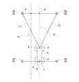
- the distance detection unit 13 detects the traveling position wireless located on the left side every time the set period elapses. A first distance L1 to the automatic traveling vehicle 1 with respect to the information tag 2a and a second distance L2 to the automatic traveling vehicle 1 with respect to the wireless information tag 2a for specifying a traveling position located on the right side are detected. Also, each time the set period elapses, the direction detection unit 14 also sets the direction of the automatic traveling vehicle 1 with respect to the wireless information tag 2a for specifying the traveling position located on the left side, and the wireless information tag for specifying the traveling position located on the right The direction of the automatic traveling vehicle 1 with respect to 2a is detected.
- the traveling control unit 11 recognizes the first distance L1 and the second distance L2 by the detection by the distance detecting unit 13, and automatically detects the traveling position specifying wireless information tags 2a on the left and right sides by the detection by the direction detecting unit 14.
- the direction of the traveling vehicle 1 is recognized, and the relative position of the automatic traveling vehicle 1 to the wireless information tag 2a for specifying the traveling position on both the left and right sides is grasped.
- the traveling position of the automatic traveling vehicle 1 is set in advance based on the arrangement position of the wireless information tag 2a for specifying the traveling position. For example, as shown by a dotted line in FIG. 4, the traveling position of the automatic traveling vehicle 1 is between the radio information tag 2a for traveling position identification located on the left side and the radio information tag 2a for traveling position identification located on the right side. A straight traveling position (traveling route) D passing through the central point E of the vehicle is set. The travel position of the automatic travel vehicle 1 is set to an area other than the travel impossible area C1 set in the travel impossible area information C stored in each wireless information tag 2.
- the traveling control unit 11 grasps in advance the setting information of the traveling position of the automatic traveling vehicle 1, and controls the traveling of the automatic traveling vehicle 1 using the setting information of the traveling position of the automatic traveling vehicle 1.
- the traveling control unit 11 grasps the relative position of the automatic traveling vehicle 1 with respect to the wireless information tags 2a for specifying the traveling positions on both the left and right sides, the traveling position (traveling ( The route D) is specified.
- the traveling control unit 11 controls the traveling position 3 by controlling the traveling unit 3 such that a speed difference corresponding to the relationship is generated between the left and right wheels according to the relationship between the first distance L1 and the second distance L2.
- the traveling of the automatic traveling vehicle 1 is controlled so as to travel.
- the relationship between the first distance L1 and the second distance L2 can be, for example, the ratio between the first distance L1 and the second distance L2, and the difference between the first distance L1 and the second distance L2.
- the automatic traveling vehicle 1 when the first distance L1 is smaller than the second distance L2, the automatic traveling vehicle 1 is positioned closer to the wireless information tag 2a for specifying the traveling position on the left side than the traveling position D. . Therefore, in the mode in which the speed of the wheel on the left side is faster than the speed of the wheel on the right side, the traveling control unit 11 generates a speed difference according to the relationship between the first distance L1 and the second distance L2 on the left and right wheels The traveling unit 3 is controlled. As a result, the autonomous traveling vehicle 1 can travel so as to approach the traveling position D, and the traveling position D can be automatically traveled.
- the detection of the distance by the distance detection unit 13 and the detection of the azimuth by the azimuth detection unit 14 are performed by the wireless communication between the vehicle communication unit 12 and the tag communication unit 21 after the set period has elapsed. It is repeated every time it is Therefore, even if the automatic traveling vehicle 1 is out of the traveling position D, the traveling control unit 11 controls the traveling of the automatic traveling vehicle 1 so as to approach the traveling position D every time the setting cycle elapses. The traveling vehicle 1 can be automatically traveled at the traveling position D.
- a speed difference corresponding to the relationship between the first distance L1 and the second distance L2 (for example, the ratio or the difference between the first distance L1 and the second distance L2) is generated at the left and right wheels
- the traveling unit 3 is controlled, the control is not limited to this control, and various controls can be applied as long as the control can adjust the traveling direction of the automatic traveling vehicle 1.
- the traveling control unit 11 can also control the traveling unit 3 such that a torque difference corresponding to the relationship between the first distance L1 and the second distance L2 occurs in the left and right wheels.
- the traveling control unit 11 can also control the steering angle of the steering wheel or the like provided in the automatic traveling vehicle 1 according to the relationship between the first distance L1 and the second distance L2.
- the traveling position D passing through the central point E is illustrated, but the traveling position identification wireless information tag 2 a located on the left side and the traveling position identification wireless information tag 2 a located on the right And if it is an area other than the non-travelable area C1 set in the non-travelable area information C stored in each wireless information tag 2, what position should be the travel position? Can be changed as appropriate.
- the wireless information tag 2 is disposed at a first predetermined interval P1 smaller than the communicable range of the wireless information tag 2 in the traveling direction as shown in FIG.
- the tag side communication unit in the next travel position specifying wireless information tags 2a in the traveling direction The wireless communication between the communication unit 21 and the vehicle communication unit 12 is possible.
- the traveling control unit 11 performs the next right and left in the traveling direction from the relative position of the automatically traveling vehicle 1 that has been grasped
- the central point E between the wireless information tags 2a for specifying the traveling positions on both sides is specified
- the traveling position D is specified
- the traveling of the automatic traveling vehicle 1 is controlled to travel the traveling position D.
- the traveling control unit 11 grasps the relative position of the automatic traveling vehicle 1 every time the relative position of the automatic traveling vehicle 1 reaches a line connecting the arrangement positions of the wireless information tags 2a for specifying the traveling positions on both left and right sides.
- the traveling of the automatic traveling vehicle 1 is controlled so that the traveling position D is traveled while switching the radio information tag 2a for specifying the traveling position of the vehicle to the radio information tag 2a for specifying the traveling position next to both right and left sides in the traveling direction doing.
- the timing at which the radio information tag 2a for identifying the traveling position for switching the relative position of the autonomous traveling vehicle 1 is switched is the same as that of the radio information tag 2a for identifying the traveling position on both left and right sides of the automatic traveling vehicle 1. It is possible to apply various timings such as the timing at which communication with the next wireless information tag 2a for specifying the traveling position becomes possible, as well as the timing each time it arrives on the line connecting the arrangement position.
- FIG. 4 exemplifies a straight traveling position D, G passing through the center point E or the deviation point F as the traveling position of the automatic traveling vehicle 1, for example, as shown in FIG.
- Curved traveling positions H and I can also be set as the traveling position of the traveling vehicle 1.
- the traveling positions H and I passing through the central point E and the deviation point F between the wireless information tags 2a for specifying the traveling positions on the left and right sides can be set as the traveling positions of the automatic traveling vehicle 1.
- the control of the traveling control unit 11 is the same as in the case of automatically traveling the linear traveling positions D and G, so the description will be omitted.
- the wireless information tag 2 located at the end of the plurality of wireless information tags 2 in the arrangement direction (vertical direction in FIG. 1) is a turning wireless information tag 2b.
- the turning information J is stored in the tag-side storage unit 22 in the turning radio information tag 2b, as shown in FIG.
- the turning information J is information for turning the automatic traveling vehicle 1.
- the turning information J is information on the traveling position (traveling path) M and turning radius N when turning and traveling. There is.
- the traveling position M is set to a region other than the non-travelable region C1 set in the non-travelable region information C stored in the turning radio information tag 2b.
- a region other than the non-travelable region C1 set in the non-travelable region information C stored in the turning radio information tag 2b For example, in FIG. 6, an arc-shaped traveling position M connecting the central point E between the left and right turning wireless information tags 2b and the central point E between the next left and right turning wireless information tags 2b is set. An example is shown.
- the traveling control unit 11 acquires turn information J by wireless communication between the tag side communication unit 21 and the vehicle side communication unit 12 in the turning radio information tag 2 b.
- the travel control unit 11 performs wireless communication between the tag-side communication unit 21 and the vehicle-side communication unit 12 in the left and right turn radio information tags 2b, and the distance detection unit 13 detects the left and right turn radio information tags.
- the distance to the automatic travel vehicle 1 with respect to 2b is detected, and the direction detection unit 14 detects the direction of the automatic travel vehicle 1 with respect to the left and right turning radio information tags 2b.
- the traveling control unit 11 grasps the relative position of the automatic traveling vehicle 1 with respect to the left and right turning radio information tags 2b.
- the traveling control unit 11 specifies the central point E which is the starting point of the traveling position M of the automatic traveling vehicle 1 included in the turning information J, and the automatic traveling vehicle 1 passes the central point E. Control the running of The traveling control unit 11 controls the traveling unit 3 to turn the automatic traveling vehicle 1 with a turning radius N included in the turning information J when the relative position of the automatic traveling vehicle 1 reaches the central point E. . Thus, the traveling control unit 11 controls the traveling of the automatic traveling vehicle 1 so as to travel the traveling position M of the automatic traveling vehicle 1, and performs the turning traveling of the automatic traveling vehicle 1.
- the traveling control unit 11 ends the turning traveling, and specifies the left and right traveling positions as described above It switches to traveling control by communication with the wireless information tag 2a.
- the traveling control unit 11 may also start the turn traveling as it is when the relative position of the automatic traveling vehicle 1 reaches the central point E where the starting position of the traveling position M starts, but it is It is also possible to start turning traveling after the traveling vehicle 1 is stopped.
- the traveling control unit 11 directly switches to traveling control by communication with the wireless information tag 2a for traveling position specification.
- the automatic traveling vehicle 1 is once stopped at the central point E, it is also possible to switch to traveling control by communication with the wireless information tag 2a for specifying the traveling position.
- the pair of left and right wireless information tags 2 located at the end of the plurality of wireless information tags 2 in the arrangement direction is the turning wireless information tag 2b.
- the traveling control unit 11 uses the relative position of the automatic traveling vehicle 1 to the wireless information tag 2 by communication with the wireless information tag 2a for specifying the traveling position and communication with the wireless information tag 2b for turning.
- the automatic traveling vehicle 1 is made to travel automatically while specifying the traveling position (traveling route).
- the automatic traveling vehicle 1 is automatically traveled at a traveling position D or the like indicated by a dotted line, along a cultivation row for cultivating fruit trees and crops overlapping with the arrangement positions of the plurality of wireless information tags 2
- the automatic traveling vehicle 1 can be reciprocated, and the automatic traveling vehicle 1 can perform the spreading work of fertilizers and the like to the cultivation sites of the fruit trees and crops and the harvesting work of the fruit trees and crops.
- an obstacle Q may be present in the traveling area A.
- the plurality of wireless information tags 2 have the obstacle Q relative to the wireless information tag 2 c in addition to the wireless information tag 2 a for traveling position specification and the wireless information tag 2 b for turning.
- stored a position as obstacle information R (refer FIG. 2) is included.
- the wireless information tag 2 disposed at a position corresponding to the position where the obstacle Q is present is used as the wireless information tag 2c for an obstacle.
- the two wireless information tags 2 located near the position where the obstacle Q is located are the wireless information tags 2c for the obstacle, but depending on where the position where the obstacle Q is located is, etc. It is possible to appropriately change which wireless information tag 2 is to be the wireless information tag 2c for an obstacle.
- obstacle information R is stored in the tag side storage unit 22 in the wireless information tag 2c for obstacles, and as shown in FIG. 7, the obstacle information R is for obstacles.
- the information indicates the relative position of the obstacle Q with respect to the wireless information tag 2c.
- the relative position of the obstacle Q with respect to the wireless information tag 2c for an obstacle is indicated by XY coordinates with the wireless information tag 2c for an obstacle as a reference point (zero point).
- the obstacle Q includes a first end spot S1 (x1, y1), a second end spot S2 (x2, y2), a third end spot S3 (x3, y3), and a fourth end spot S4 (x4, x4, x4). It exists in the area surrounded by y4).
- the direction of the Y coordinate is the direction along the traveling direction of the automatic traveling vehicle 1
- the direction of the X coordinate is the left and right direction orthogonal to the traveling direction of the automatic traveling vehicle 1
- the relative position of the obstacle Q with respect to the wireless information tag 2c for the obstacle is shown in a state in which the traveling direction of the automatic traveling vehicle 1 corresponds to that.
- wireless communication is performed between the vehicle communication unit 12 and the tag communication unit 21 of the wireless information tag 2 a for traveling position identification located on the left side.
- wireless communication is performed between the vehicle communication unit 12 and the tag communication unit 21 of the wireless information tag 2c for an obstacle located on the right side.
- the traveling control unit 11 detects the distance by the distance detecting unit 13 and detects the azimuth by the azimuth detecting unit 14, the wireless information tag 2 a for identifying the traveling position on the left and the obstacle on the right
- the relative position of the automatic traveling vehicle 1 to the wireless information tag 2c for goods is grasped.
- the travel control unit 11 stores the wireless information tag 2c for an obstacle by wireless communication between the vehicle side communication unit 12 and the tag side communication unit 21 of the wireless information tag 2c for an obstacle located on the right side. Since the received obstacle information R (see FIG. 7) is acquired, the relative position of the obstacle Q with respect to the wireless information tag 2c for the obstacle is also grasped. Thus, the traveling control unit 11 sets the relative position of the automatic traveling vehicle 1 to the wireless information tag 2a for specifying the traveling position on the left side and the wireless information tag 2c for the obstacle on the right side, and the wireless information tag 2c for the obstacle.
- the traveling position (traveling path) U for avoiding the obstacle Q is specified based on the relative position of the obstacle Q with respect to the vehicle, and the automatic traveling vehicle 1 travels so as to automatically travel the traveling position U. I have control.
- a traveling position U for avoiding the obstacle Q a central point T between the radio information tag 2a for specifying the traveling position on the left side and the third end point S3 in the obstacle Q is A traveling position U to pass is set.
- the traveling position U is a traveling position for causing the automatic traveling vehicle 1 to automatically travel continuously from the traveling position D between the wireless information tag 2a for specifying the traveling position on the left side and the wireless information tag 2c for the obstacle on the right side.
- the vehicle travels away from the traveling position D to the left by the amount of the obstacle Q from the front in the traveling direction than the position where the obstacle Q is present.
- the traveling control unit 11 is arranged by arranging the wireless information tag 2c for the obstacle at the position corresponding to the existence position of the obstacle Q. Can obtain the obstacle information R (see FIG. 7) stored in the wireless information tag 2c for the obstacle, and control the traveling of the automatic traveling vehicle 1 so as to avoid the obstacle Q. .
- the relative position of the obstacle Q with respect to the wireless information tag 2c for the obstacle is indicated by XY coordinates with the wireless information tag 2c for the obstacle as a reference point (zero point)
- a reference point zero point
- the form in which the obstacle information R is stored can be changed as appropriate.
- a field is provided in which a plurality of dots V are arranged side by side at fixed predetermined intervals W in the vertical and horizontal directions. It is also possible to show by. That is, in FIG. 9, the area surrounded by the arrangement position of the dots V indicated by hatching is the existence position of the obstacle Q. At this time, the vertical direction in FIG. 9 is the direction along the traveling direction of the automatic traveling vehicle 1, and the horizontal direction in FIG. 9 is the horizontal direction orthogonal to the traveling direction of the automatic traveling vehicle 1. The relative position of the obstacle Q with respect to the wireless information tag 2c for the obstacle is shown in a state in which the arrangement direction of V and the traveling direction of the automatic traveling vehicle 1 correspond to each other.
- wireless information tag 2 a plurality of wireless information tags 2 such as the wireless information tag 2a for travel position specification, the wireless information tag 2b for turning, and the wireless information tag 2c for obstacle are illustrated.
- These wireless information tags 2a to 2c are all the wireless information tags 2 having the same configuration, and different information to be stored in the tag-side storage unit 22 enables the wireless information tag 2a for travel position identification and turning.
- the wireless information tag 2 is either the wireless information tag 2b for the wireless communication or the wireless information tag 2c for the obstacle.
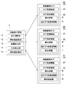
- FIG. 11 an example of the format of the information stored in the tag side storage unit 22 will be described.
- the storage area of the tag-side storage unit 22 is shown on the upper side, and a table showing the information stored in each storage area is shown on the lower side.
- the tag side storage unit 22 Each information is stored in each of predetermined storage areas.
- the position fixing ID information is unique information that the wireless information tag 2 is position fixed, and the position fixing ID information is stored in the wireless information tag 2 whose arrangement position is fixed.
- the ID information is unique information of the wireless information tag 2 and is information including address information B and travel impossible area information C.
- the ID information is stored in all of the plurality of wireless information tags 2.
- the pair information is information indicating the relationship between the wireless information tag 2 forming a pair in the left and right direction with respect to the traveling direction of the automatic traveling vehicle 1, and the pair information is a wireless information tag 2a for specifying the traveling position. It is memorized.
- the position feature information is information indicating what position the arrangement position of the wireless information tag 2 corresponds to.
- the position feature information is, for example, information indicating that the automatic traveling vehicle 1 travels in the middle of the linear traveling route in FIG. 1 and is an end of the linear traveling route in which the automatic traveling vehicle 1 travels. It is set as any information of the information which shows that, and the information which shows that it is a corner of traveling area A.
- the position feature information can be stored in all of the plurality of wireless information tags 2 in the same manner as the ID information.
- the wireless information tag 2 in which the position feature information is stored is used as the wireless information tag 2 for position feature, and in this embodiment, the wireless information tag 2a for travel position identification, the wireless information tag 2b for turning, for obstacles Any of the wireless information tags 2c can be used as the wireless information tag 2 for position feature.
- the operation instruction information is information for instructing what operation the automatic traveling vehicle 1 should perform at the arrangement position of the wireless information tag 2.
- the operation position information is, for example, turning information for causing the automatic traveling vehicle 1 to turn and / or information for stopping the automatic traveling vehicle 1.
- the obstacle information R is information indicating the relative position of the obstacle Q with respect to the wireless information tag 2, and the obstacle information R is stored in the wireless information tag 2c for the obstacle.
- the other information is information unique to the arrangement position of the wireless information tag 2, such as information of a crop grown at the arrangement position of the wireless information tag 2. It can be appropriately selected which wireless information tag 2 stores other information.
- one wireless information tag 2 can be configured as the wireless information tag 2a for travel position identification, or configured as the wireless information tag 2b for switching. Or, it can be a wireless information tag 2c for an obstacle. Further, one wireless information tag 2 can also be used as, for example, the wireless information tag 2a for travel position identification and the wireless information tag 2c for an obstacle.
- the information stored in the tag-side storage unit 22 can be rewritten. For example, by rewriting the information stored in the tag-side storage unit 22, it is possible to switch from the wireless information tag 2a for travel position identification to the turnaround The wireless information tag 2b can also be changed.
- the plurality of wireless information tags 2 are disposed so as to overlap with the cultivation row for cultivating fruit trees and crops, but the arrangement of the plurality of wireless information tags 2 As long as it is a position corresponding to a traveling position (traveling route) at which the vehicle is automatically traveled, it is possible to appropriately change how to arrange the plurality of wireless information tags 2.
- the relative position of the automatic traveling vehicle 1 with respect to the pair of left and right traveling position specifying wireless information 2a by communication between the left and right pair of traveling information wireless information tags 2a and the vehicle communication unit 12.
- the traveling control unit 11 identifies the traveling position (traveling route) E passing through the central point E etc. using the relative position of the automatic traveling vehicle 1 to the pair of left and right traveling position specifying wireless information 2a.
- the traveling control unit 11 controls the traveling of the automatic traveling vehicle 1 so as to travel the traveling position E, but the traveling control unit 11 detects the wireless information tag detected by the communication between the wireless information tag 2 and the vehicle communication unit 12
- the relative traveling position of the automatic traveling vehicle 1 with respect to 2 may be used to control the traveling of the automatic traveling vehicle 1, and the relative traveling position of the automatic traveling vehicle 1 relative to the wireless information tag 2 may be used to As in It will either can be appropriately changed.
- the traveling control unit 11 controls the traveling of the automatic traveling vehicle 1 so that the automatic traveling vehicle 1 travels forward in a state in which the traveling direction is maintained. Then, the traveling control unit 11 changes the traveling direction of the automatic traveling vehicle 1 only when there is a possibility that the automatic traveling vehicle 1 intrudes into the non-travelable region C1, and avoids the non-travelable region C1. The traveling of the automatic traveling vehicle 1 can be controlled. By performing such control, the automatic traveling vehicle 1 can be caused to travel forward in a region other than the region in which the driving can not be performed C1 while preventing entry into the driving impossible region C1.
- the present invention can be applied to various automatic travel systems that cause an automatic traveling vehicle to travel automatically.
Abstract
構成の簡素化及びコストの低減を図りながら、自動走行車両を自動走行させること。所定位置に配置された複数の無線情報タグ2と、自動走行車両1に備えられ、無線情報タグ2との間の通信を行う車両側通信部と、無線情報タグ2と車両側通信部との間での通信により、無線情報タグ2に対する方位及び無線情報タグ2に対する距離を取得して無線情報タグ2に対する相対位置を検出する相対位置検出部と、相対位置検出部にて検出される相対位置に基づいて、自動走行車両1の走行を制御する走行制御部とが備えられている。
Description
本発明は、自動走行車両を自動走行させる自動走行システムに関する。
上記の自動走行システムでは、自動走行車両として、トラクタや田植機等の作業車両が備えられ、その作業車両を自動走行させるための目標走行経路を圃場等の走行領域に予め設定している。作業車両等に衛星測位システムを搭載することで、作業車両の現在位置を取得可能とし、取得される作業車両の現在位置に基づいて、作業車両が目標走行経路に沿って自動走行するように、作業車両の走行を制御している(例えば、特許文献1参照。)。
特許文献1に記載のシステムでは、目標走行経路を予め設定しておく必要があるとともに、高価な衛星測位システムを備えることが必要となるので、構成の複雑化やコストアップを招くことになる。
この実情に鑑み、本発明の主たる課題は、構成の簡素化及びコストの低減を図りながら、自動走行車両を自動走行させることができる自動走行システムを提供する点にある。
本発明の第1特徴構成は、所定位置に配置された複数の無線情報タグと、
自動走行車両に備えられ、前記無線情報タグとの間の通信を行う車両側通信部と、
前記無線情報タグと前記車両側通信部との間での通信により、前記無線情報タグに対する方位及び前記無線情報タグに対する距離を取得して前記無線情報タグに対する相対位置を検出する相対位置検出部と、
前記相対位置検出部にて検出される相対位置に基づいて、前記自動走行車両の走行を制御する走行制御部とが備えられている点にある。
自動走行車両に備えられ、前記無線情報タグとの間の通信を行う車両側通信部と、
前記無線情報タグと前記車両側通信部との間での通信により、前記無線情報タグに対する方位及び前記無線情報タグに対する距離を取得して前記無線情報タグに対する相対位置を検出する相対位置検出部と、
前記相対位置検出部にて検出される相対位置に基づいて、前記自動走行車両の走行を制御する走行制御部とが備えられている点にある。
本構成によれば、相対位置検出部は、無線情報タグと車両側通信部との間での通信により、無線情報タグに対する自動走行車両の相対位置を検出することができる。よって、自動走行車両を自動走行させる走行位置に対応して無線情報タグを配置することで、相対位置検出部にて検出する無線情報タグに対する自動走行車両の相対位置は、自動走行車両を自動走行させる走行位置に対応した位置となる。これにより、走行制御部は、相対位置検出部にて検出する無線情報タグに対する自動走行車両の相対位置を用いて、自動走行車両を自動走行させる走行位置を特定することができ、その走行位置を走行させるように、自動走行車両の走行を制御することができる。その結果、目標走行経路を予め設定しておく必要もなく、高価な衛星測位システムを備えなくてもよく、構成の簡素化及びコストの低減を図りながら、自動走行車両を自動走行させることができる。
本発明の第2特徴構成は、複数の無線情報タグは、前記自動走行車両の進行方向に対して左右方向に間隔を隔てて一対配置された走行位置特定用の無線情報タグを含み、
前記相対位置検出部は、一対の走行位置特定用の無線情報タグの夫々に対する相対位置を検出し、
前記走行制御部は、前記相対位置検出部にて検出される一対の走行位置特定用の無線情報タグの夫々に対する相対位置に基づいて、一対の走行位置特定用の無線情報タグの間を走行するように前記自動走行車両の走行を制御している点にある。
前記相対位置検出部は、一対の走行位置特定用の無線情報タグの夫々に対する相対位置を検出し、
前記走行制御部は、前記相対位置検出部にて検出される一対の走行位置特定用の無線情報タグの夫々に対する相対位置に基づいて、一対の走行位置特定用の無線情報タグの間を走行するように前記自動走行車両の走行を制御している点にある。
本構成によれば、自動走行車両を自動走行させる走行位置に対して左右方向に一対の走行位置特定用の無線情報タグを配置することで、相対位置検出部にて検出する一対の走行位置特定用の無線情報タグの夫々に対する自動走行車両の相対位置は、走行位置に対応する位置となる。これにより、走行制御部は、相対位置検出部にて検出する一対の走行位置特定用の無線情報タグの夫々に対する自動走行車両の相対位置を用いて、一対の走行位置特定用の無線情報タグの間の走行位置を特定することができ、その走行位置を走行させるように、自動走行車両の走行を制御することができる。よって、走行制御部は、一対の走行位置特定用の無線情報タグの間の走行位置を正確に特定しながら、自動走行車両を適切に自動走行させることができる。
本発明の第3特徴構成は、前記走行制御部は、一対の走行位置特定用の無線情報タグの一方側に対する距離と他方側に対する距離との関係に応じて、前記自動走行車両の走行を制御することで、前記自動走行車両を、一対の走行位置特定用の無線情報タグの間を走行させる点にある。
本構成によれば、走行制御部は、一対の走行位置特定用の無線情報タグの一方側に対する距離と他方側に対する距離との関係に応じて、自動走行車両の走行を制御するという簡易な制御を行うことで、一対の走行位置特定用の無線情報タグの間の走行位置で自動走行車両を自動走行させることができる。よって、構成の簡素化を図りながら、自動走行車両を自動走行させることができる。
本発明の第4特徴構成は、複数の無線情報タグは、その無線情報タグに対する障害物の相対位置を障害物情報として記憶している障害物用の無線情報タグを含み、
前記走行制御部は、前記障害物用の無線情報タグと前記車両側通信部との間での通信により取得される障害物情報に基づいて、障害物を回避するように前記自動走行車両の走行を制御している点にある。
前記走行制御部は、前記障害物用の無線情報タグと前記車両側通信部との間での通信により取得される障害物情報に基づいて、障害物を回避するように前記自動走行車両の走行を制御している点にある。
本構成によれば、障害物用の無線情報タグには、無線情報タグに対する障害物の相対位置を示す障害物情報が記憶されているので、走行制御部は、障害物用の無線情報タグと車両側通信部との通信により障害物情報を取得することで、相対位置検出部にて検出される障害物用の無線情報タグに対する自動走行車両の相対位置に加えて、障害物用の無線情報タグに対する障害物の相対位置を把握することができる。これにより、走行制御部は、障害物用の無線情報タグの配置位置を基準として、自動走行車両の相対位置、及び、障害物の相対位置を用いて、自動走行車両に対する障害物の相対位置を特定することができ、その特定した障害物を回避するように自動走行車両の走行を制御することができる。よって、走行対象となる走行領域内に障害物が存在しても、その障害物を回避するように自動走行車両を自動走行させることができる。
本発明の第5特徴構成は、複数の無線情報タグは、前記自動走行車両を転回走行させる転回情報を記憶している転回用の無線情報タグを含み、
前記走行制御部は、前記転回用の無線情報タグと前記通信部との間での通信により取得される転回情報に基づいて、転回走行させるように前記自動走行車両の走行を制御している点にある。
前記走行制御部は、前記転回用の無線情報タグと前記通信部との間での通信により取得される転回情報に基づいて、転回走行させるように前記自動走行車両の走行を制御している点にある。
本構成によれば、転回用の無線情報タグには、自動走行車両を転回走行させる転回情報が記憶されているので、走行制御部は、転回用の無線情報タグと車両側通信部との通信により転回情報を取得することができる。転回情報は、例えば、転回用の無線情報タグに対してどのような位置を転回走行させるか、転回用の無線情報タグに対してどの方向に転回走行させるか等、自動走行車両を転回走行させるための各種の走行条件等を示すものである。これにより、走行制御部は、転回情報を取得することで、その転回情報にて示された各種の走行条件に応じて、自動走行車両を簡易に転回走行させることができる。しかも、走行対象となる走行領域において、自動走行車両を前進走行させるだけでなく、自動走行車両を転回走行させることもできるので、走行領域において自動走行車両を効率よく走行させて、作業効率の向上を図ることができる。
本発明の第6特徴構成は、複数の無線情報タグは、自己の配置位置に関する位置特徴情報を記憶している位置特徴用の無線情報タグを含んでいる点にある。
本構成によれば、車両側通信部は、無線情報タグとの間の通信を行うことで、その無線情報タグの配置位置に関する位置特徴情報を取得することができる。ここで、位置特徴情報は、例えば、自動走行車両を走行させる経路上において、無線情報タグの配置位置がどのような位置に相当するのかを示す情報である。例えば、位置特徴情報は、自動走行車両を直線走行させる経路の中央部であることを示す情報や、自動走行車両を転回走行させる開始地点であることを示す情報等とすることができる。これにより、走行制御部は、位置特徴情報からどのような位置に配置された無線情報タグと無線通信しているのかを把握しながら、自動走行車両を自動走行させることができるので、自動走行を効率よく行うことができる。
本発明に係る自動走行システムの実施形態を図面に基づいて説明する。
この自動走行システムは、例えば、果樹を栽培する果樹園やハウス内で各種の作物を栽培するハウス施設等に適用され、自動走行車両1を自動走行させることで、農薬、肥料及び除草剤の散布作業や収穫作業等を行うようにしている。自動走行システムは、図1に示すように、果樹園内やハウス内を走行対象とする走行領域Aとしており、その走行領域A内で自動走行車両1を自動走行させるために、所定位置に配置された複数の無線情報タグ2が備えられている。また、自動走行車両1の走行領域Aは、屋外だけではなく、建物内等の屋内とすることもできる。
この自動走行システムは、例えば、果樹を栽培する果樹園やハウス内で各種の作物を栽培するハウス施設等に適用され、自動走行車両1を自動走行させることで、農薬、肥料及び除草剤の散布作業や収穫作業等を行うようにしている。自動走行システムは、図1に示すように、果樹園内やハウス内を走行対象とする走行領域Aとしており、その走行領域A内で自動走行車両1を自動走行させるために、所定位置に配置された複数の無線情報タグ2が備えられている。また、自動走行車両1の走行領域Aは、屋外だけではなく、建物内等の屋内とすることもできる。
図1において、図示は省略するが、複数の果樹や作物が図中上下方向に沿って一列に並ぶ状態で栽培しており、その栽培列を図中左右方向に間隔を隔てて複数備えられている。そして、複数の無線情報タグ2は、複数の栽培列と重複するように配置されており、果樹や作物の間等を利用して、無線情報タグ2が設置されている。
自動走行車両1は、例えば、農薬、肥料及び除草剤の散布作業車両や収穫作業車両等の作業車両を適用することができるが、その他各種の作業車両を適用することも可能である。自動走行車両1は、複数の車輪を有する走行部3と、その走行部3にて支持される車体部4とが備えられている。図示は省略するが、自動走行車両1を散布作業車両とする場合は、車体部4に散布装置等の各種の装置が備えられ、自動走行車両1を収穫作業車両とする場合は、車体部4に収穫装置等の各種の装置が備えられている。
自動走行車両1には、図2に示すように、自動走行車両1の走行を制御する走行制御部11と、無線情報タグ2との間の通信を行う車両側通信部12と、無線情報タグ2と車両側通信部12との間での通信により無線情報タグ2に対する自動走行車両1までの距離を検出する距離検出部13と、無線情報タグ2と車両側通信部12との間での通信により無線情報タグ2に対する自動走行車両1の方位を検出する方位検出部14と、各種の情報を記憶する不揮発性メモリ等を有する車両側記憶部15とが備えられている。相対位置検出部は、距離検出部13と方位検出部14とを備えて構成されている。
走行制御部11は、例えば、自動走行車両1の進行方向が所望の進行方向となり、車速が所望の車速となるように走行部3を制御している。車両側通信部12は、アンテナ、リーダ、ライタ等を有しており、所定周波数の電波を用いた無線により無線情報タグ2との間で通信している。距離検出部13による距離の検出手法、及び、方位検出部14による方位の検出手法については、例えば、自動走行車両1の移動中に無線情報タグ2から受信される信号の位相、その位相の変化の傾きが反転されたタイミングにおける自動走行車両1の位置、及び、自動走行車両1の移動距離等を用いて、無線情報タグ2に対する自動走行車両1までの距離、及び、無線情報タグ2に対する自動走行車両1の方位を演算している。この検出手法については、例えば、特許第5987187号公報等により公知技術であるので、詳細な説明は省略する。また、距離検出部13による距離の検出手法、及び、方位検出部14による方位の検出手法として、特許第5987187号公報等にて開示された公知技術とは別の検出手法を用いることもできる。
無線情報タグ2には、図2に示すように、車両側通信部12との間での通信を行うアンテナ等を有するタグ側通信部21と、各種の情報を記憶する不揮発性メモリ等を有するタグ側記憶部22とが備えられている。無線情報タグ2は、自動走行車両1から送信される電波をエネルギー源として動作するパッシブ型に構成されており、バッテリーを備えていない。無線情報タグ2の通信可能範囲は、例えば、3~5m以内となっている。
複数の無線情報タグ2は、走行領域Aにおいて、自動走行車両1を自動走行させる走行位置を特定するために用いられている。複数の無線情報タグ2の配置位置は、自動走行車両1を自動走行させる走行位置に対応する位置に設定されている。
図1では、図中点線にて示すように、上下方向の一端側から他端側に向けて直線状に自動走行車両1を走行させ、上下方向の他端側にて自動走行車両1を転回させて進行方向を反転させ、上下方向の他端側から一端側に向けて直線状に自動走行車両1を走行させる走行形態を繰り返し行い、自動走行車両1を往復走行させるための走行位置(走行経路)を例示している。
そこで、図1中上下方向に自動走行車両1を走行させるために、複数の無線情報タグ2の配置位置は、図1中上下方向に並ぶように設定されている。無線情報タグ2を配置する所定位置の夫々には、例えば、図3に示すように、上下方向に延びる支持柱5が配置されており、支持柱5の上下方向の途中部に無線情報タグ2が取り付けられている。無線情報タグ2は、例えば、両面接着テープ等の固定具を用いて支持柱5に固定され、揺れや移動が防止された状態で支持柱5に取り付けられている。ちなみに、無線情報タグ2を嵌め込んで収容可能な収容ケース等を予め支柱柱5に固定しておき、その収容ケースに無線情報タグ2を嵌め込んで収容させることで、無線情報タグ2を所定位置に取り付けることもできる。
自動走行車両1を自動走行させる際には、自動走行車両1が移動することで、図2に示すように、車両側通信部12とタグ側通信部21との間での無線通信が行われる。この無線通信により、距離検出部13が、無線情報タグ2に対する自動走行車両1までの距離を検出し、且つ、方位検出部14が、無線情報タグ2に対する自動走行車両1の方位を検出する。走行制御部11は、距離検出部13にて検出される無線情報タグ2に対する自動走行車両1までの距離、及び、方位検出部14にて検出される無線情報タグ2に対する自動走行車両1の方位に基づいて、無線情報タグ2に対する自動走行車両1の相対位置を把握することができる。よって、自動走行車両1の走行位置を、無線情報タグ2の配置位置を基準にして予め設定しておくことで、走行制御部11は、予め設定された自動走行車両1の走行位置を特定し、その特定した走行位置を走行するように、自動走行車両1の走行を制御している。自動走行車両1の走行位置の特定方法やそのときの自動走行車両1の自動走行等については後述する。
複数の無線情報タグ2は、図1に示すように、自動走行車両1の進行方向(図1中上下方向)に対して左右方向(図1中左右方向)に間隔を隔てて一対配置された走行位置特定用の無線情報タグ2aと、自動走行車両1を転回走行させる転回情報Jを記憶している転回用の無線情報タグ2bとが含まれている。
左右一対の走行位置特定用の無線情報タグ2aは、図1中上下方向の一端側から他端側又は他端側から一端側に向けて自動走行車両1を走行させるための走行位置に対応して、自動走行車両1の進行方向に第1所定間隔P1を隔てて並ぶ状態で配置されている。第1所定間隔P1は、無線情報タグ2の通信可能範囲よりも小さな値が設定されている。また、複数の無線情報タグ2は、左右方向(図1中左右方向)においても、左右一対の無線情報タグ2の間の間隔が一定間隔となるように配置されており、その間隔も無線情報タグ2の通信可能範囲よりも小さな値が設定されている。これにより、自動走行車両1が走行するときには、少なくとも進行方向及び左右方向で2つずつの合計4つの無線情報タグ2と自動走行車両1の車両側通信部12との間で無線通信可能となっている。
転回用の無線情報タグ2bは、自動走行車両1を転回させる位置に対応して配置されている。図1では、図中上下方向の一端側と他端側とで自動走行車両1を転回させるので、複数の無線情報タグ2のうち、図中上下方向の上端部及び下端部に位置する無線情報タグ2が、転回用の無線情報タグ2bとなっている。
走行位置特定用の無線情報タグ2a、及び、転回用の無線情報タグ2bは、番地情報Bと走行不可能領域情報Cとがタグ側記憶部22に記憶されている。これにより、自動走行車両1は、車両側通信部12とタグ側通信部21との間での通信により、走行制御部11が番地情報B及び走行不可能領域情報Cを取得可能に構成されている。
番地情報Bは、無線情報タグ2の配置位置がどの番地に位置するのかを示す情報である。例えば、図1中、一番左側で且つ一番下側に位置する無線情報タグ2の配置位置を「1-1番地」とし、この無線情報タグ2を基準番地として2つの座標を想定することで、番地情報Bを2つの数字にて示すことができる。例えば、左側から二番目で且つ一番下側に位置する無線情報タグ2の配置位置を「2-1番地」とし、無線情報タグ2の配置位置が右側になる程、一つ目の数字が大きくなるように番地情報Bを設定することができる。また、一番左側で且つ下から二番目に位置する無線情報タグ2の配置位置を「1-2番地」とし、無線情報タグ2の配置位置が上方側になる程、二つ目の数字が大きくなるように番地情報Bを設定することができる。よって、一番右側で且つ一番上側に位置する無線情報タグ2の配置位置を「4-7番地」と設定することができる。このように設定された番地情報Bが、複数の無線情報タグ2の夫々におけるタグ側記憶部22に記憶されている。
走行不可能領域情報Cは、自動走行車両1が走行不可能な領域を示す情報となっている。例えば、無線情報タグ2に対して自動走行車両1が接近し過ぎると、作物や無線情報タグ2に対する自動走行車両1の接触等を招く可能性があるので、図10に示すように、無線情報タグ2から所定距離までの範囲を走行不可能領域C1(図10中、無線情報タグ2から点線までの領域)としている。
走行不可能領域C1は、無線情報タグ2の配置位置等に応じて、どのような領域を設定するかは変更可能となっているので、図10を用いて走行不可能領域C1について説明を加える。
図10(a)は、転回用の無線情報タグ2b等のように、複数の無線情報タグ2の並び方向(図1中、上下方向)の端部に無線情報タグ2が配置された場合を示しており、図10(b)は、走行位置特定用の無線情報タグ2a等のように、複数の無線情報タグ2の並び方向(図1中、上下方向)の途中部に無線情報タグ2が配置された場合を示している。図10(a)では、複数の無線情報タグ2の並び方向(図1中、上下方向)の上端部に無線情報タグ2が配置された場合を示しており、無線情報タグ2の配置位置から左右方向の両側に第1所定距離K1までの範囲であり、且つ、無線情報タグ2の配置位置から上下方向の下方側に第2所定距離K2までの範囲を走行不可能領域C1に設定している。図10(b)では、無線情報タグ2の配置位置から左右方向の両側に第3所定距離K3までの範囲であり、且つ、無線情報タグ2の配置位置から上下方向の両側に第4所定距離K4までの範囲を走行不可能領域C1に設定している。
図10(c)は、図1では図示していないものの、例えば、壁部7等に無線情報タグ2が配置された場合を示しており、図10(d)は、壁部7等のコーナー部8に無線情報タグ2が配置された場合を示している。図10(c)では、壁部7から第5所定距離K5までの範囲を走行不可能領域C1に設定している。図10(d)でも、壁部7から第6所定距離K6までの範囲を走行不可能領域C1に設定しており、コーナー部8の形状に応じた屈曲状の走行不可能領域C1が設定されている。
走行不可能領域C1については、無線情報タグ2の配置位置を基準として設定する領域であれば、どのような領域を設定するかは適宜変更が可能である。例えば、図10(e)に示すように、無線情報タグ2の配置位置から左右方向の両側に第7所定距離K7までの範囲であり、且つ、無線情報タグ2の配置位置から上下方向の両側に第8所定距離Kまでの矩形状の範囲を走行不可能領域C1に設定することもできる。図10(f)に示すように、無線情報タグ2の配置位置を中心として、無線情報タグ2の配置位置から第9所定距離K9を半径とする円形状の範囲を走行不可能領域C1に設定することもできる。
このように、番地情報B及び走行不可能領域情報Cが設定されているので、自動走行車両1が走行するときには、車両側通信部12とタグ側通信部21との間での通信により、走行制御部11が、番地情報B及び走行不可能領域情報Cを取得している。よって、走行制御部11は、無線通信している無線情報タグ2の番地情報Bを把握しながら、走行不可能領域C1を走行しないように、自動走行車両1の走行を制御している。
走行制御部11は、車両側通信部12とタグ側通信部21との間での通信により、番地情報Bを取得しているので、どの番地に配置された無線情報タグ2と通信しているかを把握している。そこで、走行制御部11は、自動走行車両1の自動走行中に、故障等により通信不可能な無線情報タグ2が存在すると、その無線情報タグ2がどの番地に配置されているかを把握することができ、複数の無線情報タグ2のうち、どの無線情報タグ2が故障であるかを特定できるようにしている。また、走行制御部11は、自動走行車両1の自動走行中に、故障等により通信不可能な無線情報タグ2が存在すると、例えば、自動走行車両1の自動走行を停止させるようにしている。
以下、図4に基づいて、走行位置特定用の無線情報タグ2を用いた走行位置の特定方法、及び、そのときの自動走行車両1の自動走行について説明する。
走行位置特定用の無線情報タグ2aは、自動走行車両1の進行方向に対して左右方向に一対配置されているので、自動走行車両1が走行するときには、車両側通信部12と左側に位置する走行位置特定用の無線情報タグ2aのタグ側通信部21との間で無線通信するとともに、車両側通信部12と右側に位置する走行位置特定用の無線情報タグ2aのタグ側通信部21との間で無線通信する。そして、車両側通信部12とタグ側通信部21との間で無線通信は、設定周期が経過する毎に繰り返し行われている。設定周期は、時間にて設定することも可能であるが、例えば、自動走行車両1が設定距離移動する毎等、時間以外の条件を用いて設定することもできる。
このように、車両側通信部12とタグ側通信部21との間で無線通信が行われると、距離検出部13は、設定周期が経過する毎に、左側に位置する走行位置特定用の無線情報タグ2aに対する自動走行車両1までの第1距離L1と、右側に位置する走行位置特定用の無線情報タグ2aに対する自動走行車両1までの第2距離L2とを検出する。また、方位検出部14も、設定周期が経過する毎に、左側に位置する走行位置特定用の無線情報タグ2aに対する自動走行車両1の方位と、右側に位置する走行位置特定用の無線情報タグ2aに対する自動走行車両1の方位とを検出する。走行制御部11は、距離検出部13による検出によって第1距離L1と第2距離L2を認識しているとともに、方位検出部14による検出によって左右両側の走行位置特定用の無線情報タグ2aに対する自動走行車両1の方位を認識しており、左右両側の走行位置特定用の無線情報タグ2aに対する自動走行車両1の相対位置を把握している。
自動走行車両1の走行位置については、走行位置特定用の無線情報タグ2aの配置位置を基準として予め設定されている。例えば、図4中点線で示すように、自動走行車両1の走行位置が、左側に位置する走行位置特定用の無線情報タグ2aと右側に位置する走行位置特定用の無線情報タグ2aとの間の中央地点Eを通過する直線状の走行位置(走行経路)Dに設定されている。自動走行車両1の走行位置は、各無線情報タグ2に記憶されている走行不可能領域情報Cにて設定されている走行不可能領域C1以外の領域に設定されている。走行制御部11は、自動走行車両1の走行位置の設定情報を予め把握しており、自動走行車両1の走行位置の設定情報を用いて、自動走行車両1の走行を制御している。
走行制御部11は、左右両側の走行位置特定用の無線情報タグ2aに対する自動走行車両1の相対位置を把握しているので、その相対位置から中央地点Eを特定することで、走行位置(走行経路)Dを特定している。走行制御部11は、第1距離L1と第2距離L2との関係に応じて、その関係に応じた速度差が左右の車輪に生じるように走行部3を制御することで、走行位置Dを走行するように、自動走行車両1の走行を制御している。ちなみに、第1距離L1と第2距離L2との関係は、例えば、第1距離L1と第2距離L2との比や、第1距離L1と第2距離L2との差とすることができる。
例えば、第1距離L1の方が第2距離L2よりも小さい場合には、自動走行車両1が走行位置Dよりも左側の走行位置特定用の無線情報タグ2aに接近する側に位置している。よって、走行制御部11は、左側の車輪の速度が右側の車輪の速度よりも速くする形態で、第1距離L1と第2距離L2との関係に応じた速度差が左右の車輪に生じるように走行部3を制御している。これにより、自動走行車両1が走行位置Dに接近するように走行させることができ、走行位置Dを自動走行させることができる。
上述の如く、距離検出部13による距離の検出、及び、方位検出部14による方位の検出は、設定周期が経過して車両側通信部12とタグ側通信部21との間で無線通信が行われる毎に繰り返し行われる。よって、自動走行車両1が走行位置Dから外れていても、走行制御部11が、設定周期が経過する毎に走行位置Dに接近するように自動走行車両1の走行を制御することになり、走行位置Dにて自動走行車両1を自動走行させることができる。
走行制御部11の制御として、第1距離L1と第2距離L2との関係(例えば、第1距離L1と第2距離L2との比や差)に応じた速度差が左右の車輪に生じるように走行部3を制御しているが、この制御に限らず、自動走行車両1の進行方向を調整可能な制御であれば、各種の制御を適用可能である。例えば、走行制御部11は、第1距離L1と第2距離L2との関係に応じたトルク差が左右の車輪に生じるように走行部3を制御することもできる。また、走行制御部11は、第1距離L1と第2距離L2との関係に応じて、自動走行車両1に備えられるステアリングホイール等の操舵角度を制御することもできる。
自動走行車両1の走行位置について、中央地点Eを通過する走行位置Dを例示したが、左側に位置する走行位置特定用の無線情報タグ2aと右側に位置する走行位置特定用の無線情報タグ2aとの間であり、各無線情報タグ2に記憶されている走行不可能領域情報Cにて設定されている走行不可能領域C1以外の領域であれば、どのような位置を走行位置とするかは適宜変更が可能である。
例えば、図4中一点鎖線にて示すように、自動走行車両1の走行位置を、中央地点Eよりも左側に位置する走行位置特定用の無線情報タグ2aに接近するように偏倚させた偏倚地点Fを通過する走行位置(走行経路)Gに設定することもできる。この場合も、走行制御部11は、左右両側の走行位置特定用の無線情報タグ2aに対する自動走行車両1の相対位置を把握しているので、その相対位置から偏倚地点Fを特定することで、走行位置Gを特定することができる。
走行制御部11は、左右両側の走行位置特定用の無線情報タグ2aに対する自動走行車両1の相対位置が左右両側の走行位置特定用の無線情報タグ2aの配置位置を繋ぐライン上に到達すると、進行方向で次の左右両側の走行位置特定用の無線情報タグ2aにおけるタグ側通信部21と車両側通信部12との間での無線通信によって、距離検出部13の検出及び方位検出部14の検出を行い、進行方向で次の左右両側の走行位置特定用の無線情報タグ2aに対する自動走行車両1の相対位置を把握している。ちなみに、上述の如く、進行方向では、図1に示すように、無線情報タグ2の通信可能範囲よりも小さい第1所定間隔P1を隔てて無線情報タグ2が配置されているので、自動走行車両1の相対位置が左右両側の走行位置特定用の無線情報タグ2aの配置位置を繋ぐライン上に到達すると、進行方向で次の左右両側の走行位置特定用の無線情報タグ2aにおけるタグ側通信部21と車両側通信部12との間での無線通信が可能となっている。
このように、タグ側通信部21と車両側通信部12との間での無線通信が行われることで、走行制御部11は、把握した自動走行車両1の相対位置から進行方向で次の左右両側の走行位置特定用の無線情報タグ2aの間の中央地点Eを特定して、走行位置Dを特定し、その走行位置Dを走行するように、自動走行車両1の走行を制御している。走行制御部11は、自動走行車両1の相対位置が左右両側の走行位置特定用の無線情報タグ2aの配置位置を繋ぐライン上に到達する毎に、自動走行車両1の相対位置を把握するための走行位置特定用の無線情報タグ2aを、進行方向で次の左右両側の走行位置特定用の無線情報タグ2aに切り替えながら、走行位置Dを走行するように、自動走行車両1の走行を制御している。
ここで、自動走行車両1の相対位置を把握するための走行位置特定用の無線情報タグ2aを切り替えるタイミングは、自動走行車両1の相対位置が左右両側の走行位置特定用の無線情報タグ2aの配置位置を繋ぐライン上に到達する毎のタイミングに限らず、次の走行位置特定用の無線情報タグ2aとの間で通信可能となったタイミング等、各種のタイミングを適用可能である。
図4では、自動走行車両1の走行位置として、中央地点Eや偏倚地点Fを通過する直線状の走行位置D,Gを設定したものを例示したが、例えば、図5に示すように、自動走行車両1の走行位置として、カーブ状の走行位置H,Iを設定することもできる。この場合も、自動走行車両1の走行位置として、左右両側の走行位置特定用の無線情報タグ2aの間の中央地点Eや偏倚地点Fを通過する走行位置H,Iに設定することができる。走行制御部11の制御については、直線状の走行位置D,Gを自動走行させる場合と同様であるので、説明は省略する。
図6等に基づいて、自動走行車両1を転回走行させる場合について説明する。
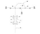
図1に示すように、複数の無線情報タグ2の並び方向(図1中上下方向)の端部に位置する無線情報タグ2が転回用の無線情報タグ2bとなっている。転回用の無線情報タグ2bには、図2に示すように、番地情報Bと走行不可能領域情報Cに加えて、転回情報Jがタグ側記憶部22に記憶されている。転回情報Jは、自動走行車両1を転回走行させるための情報であり、例えば、図6に示すように、転回走行するときの走行位置(走行経路)M及び旋回半径N等に関する情報となっている。走行位置Mについては、転回用の無線情報タグ2bに記憶されている走行不可能領域情報Cにて設定されている走行不可能領域C1以外の領域に設定されている。例えば、図6では、左右の転回用の無線情報タグ2bの間の中央地点Eと次の左右の転回用の無線情報タグ2bの間の中央地点Eとを結ぶ円弧状の走行位置Mを設定した例を示している。
図1に示すように、複数の無線情報タグ2の並び方向(図1中上下方向)の端部に位置する無線情報タグ2が転回用の無線情報タグ2bとなっている。転回用の無線情報タグ2bには、図2に示すように、番地情報Bと走行不可能領域情報Cに加えて、転回情報Jがタグ側記憶部22に記憶されている。転回情報Jは、自動走行車両1を転回走行させるための情報であり、例えば、図6に示すように、転回走行するときの走行位置(走行経路)M及び旋回半径N等に関する情報となっている。走行位置Mについては、転回用の無線情報タグ2bに記憶されている走行不可能領域情報Cにて設定されている走行不可能領域C1以外の領域に設定されている。例えば、図6では、左右の転回用の無線情報タグ2bの間の中央地点Eと次の左右の転回用の無線情報タグ2bの間の中央地点Eとを結ぶ円弧状の走行位置Mを設定した例を示している。
走行制御部11は、転回用の無線情報タグ2bにおけるタグ側通信部21と車両側通信部12との間での無線通信により、転回情報Jを取得している。走行制御部11は、左右の転回用の無線情報タグ2bにおけるタグ側通信部21と車両側通信部12との間での無線通信によって、距離検出部13が、左右の転回用の無線情報タグ2bに対する自動走行車両1までの距離を検出しており、方位検出部14が、左右の転回用の無線情報タグ2bに対する自動走行車両1の方位を検出している。これにより、走行制御部11は、左右の転回用の無線情報タグ2bに対する自動走行車両1の相対位置を把握している。そこで、走行制御部11は、転回情報Jに含まれる自動走行車両1の走行位置Mの開始地点となる中央地点Eを特定しており、その中央地点Eを通過するように、自動走行車両1の走行を制御している。走行制御部11は、自動走行車両1の相対位置が中央地点Eに到達すると、転回情報Jに含まれる旋回半径Nにて自動走行車両1を旋回走行させるように走行部3を制御している。これにより、走行制御部11は、自動走行車両1の走行位置Mを走行するように、自動走行車両1の走行を制御して、自動走行車両1の転回走行を行っている。走行制御部11は、自動走行車両1の相対位置が自動走行車両1の走行位置Mの終了地点となる中央地点Eに到達すると、転回走行を終了して、上述の如く、左右の走行位置特定用の無線情報タグ2aとの通信による走行制御に切り替えている。
走行制御部11は、自動走行車両1の相対位置が走行位置Mの開始地点となる中央地点Eに到達すると、そのまま転回走行を開始させることも可能であるが、一旦、中央地点Eにて自動走行車両1を停止させた後、転回走行を開始させることも可能である。また、走行制御部11は、自動走行車両1の相対位置が走行位置Mの開始地点となる中央地点Eに到達すると、そのまま走行位置特定用の無線情報タグ2aとの通信による走行制御に切り替えることも可能であるが、一旦、中央地点Eにて自動走行車両1を停止させた後、走行位置特定用の無線情報タグ2aとの通信による走行制御に切り替えることも可能である。
ちなみに、図1や図6では、複数の無線情報タグ2の並び方向の端部に位置する左右一対の無線情報タグ2を転回用の無線情報タグ2bとしているが、左右一対の無線情報タグ2のうち、転回走行する側(図1及び図6中右側)に位置する無線情報タグ2のみを転回用の無線情報タグ2bとして、自動走行車両1を転回走行させることもできる。
このようにして、走行制御部11は、走行位置特定用の無線情報タグ2aとの通信や転回用の無線情報タグ2bとの通信により、無線情報タグ2に対する自動走行車両1の相対位置を用いて走行位置(走行経路)を特定しながら、自動走行車両1を自動走行させている。図1に示すものでは、点線にて示す走行位置D等にて自動走行車両1を自動走行させることで、複数の無線情報タグ2の配置位置と重複する果樹や作物を栽培する栽培列に沿って自動走行車両1を往復走行させることができ、自動走行車両1によって果樹や作物の栽培箇所への肥料等の散布作業や果樹や作物の収穫作業等を行うことができる。
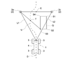
図1に示すように、走行領域A内に障害物Qが存在する場合がある。このような場合には、障害物Qを回避して自動走行車両1を自動走行させることが必要となる。そこで、複数の無線情報タグ2は、図1に示すように、走行位置特定用の無線情報タグ2a、及び、転回用の無線情報タグ2bに加えて、無線情報タグ2cに対する障害物Qの相対位置を障害物情報R(図2参照)として記憶している障害物用の無線情報タグ2cを含んでいる。複数の無線情報タグ2のうち、障害物Qの存在位置に対応する位置に配置される無線情報タグ2を、障害物用の無線情報タグ2cとしている。図1では、障害物Qの存在位置の近くに位置にする2つの無線情報タグ2を障害物用の無線情報タグ2cとしているが、障害物Qの存在位置がどこに位置するか等に応じて、どの無線情報タグ2を障害物用の無線情報タグ2cとするかは適宜変更が可能である。
図7及び図8に基づいて、障害物Qを回避して自動走行車両1を自動走行させる場合について説明する。
図2に示すように、障害物用の無線情報タグ2cには、障害物情報Rがタグ側記憶部22に記憶されており、図7に示すように、障害物情報Rは、障害物用の無線情報タグ2cに対する障害物Qの相対位置を示す情報となっている。図7に示すものでは、障害物用の無線情報タグ2cに対する障害物Qの相対位置を、障害物用の無線情報タグ2cを基準点(ゼロ点)とするXY座標にて示している。障害物Qは、第1端部地点S1(x1、y1)と第2端部地点S2(x2、y2)と第3端部地点S3(x3、y3)と第4端部地点S4(x4、y4)にて囲まれた領域に存在している。このとき、Y座標の方向が自動走行車両1の進行方向に沿う方向となっており、X座標の方向が自動走行車両1の進行方向に直交する左右方向となっており、XY座標の方向と自動走行車両1の進行方向とが対応する状態で、障害物用の無線情報タグ2cに対する障害物Qの相対位置が示されている。
図2に示すように、障害物用の無線情報タグ2cには、障害物情報Rがタグ側記憶部22に記憶されており、図7に示すように、障害物情報Rは、障害物用の無線情報タグ2cに対する障害物Qの相対位置を示す情報となっている。図7に示すものでは、障害物用の無線情報タグ2cに対する障害物Qの相対位置を、障害物用の無線情報タグ2cを基準点(ゼロ点)とするXY座標にて示している。障害物Qは、第1端部地点S1(x1、y1)と第2端部地点S2(x2、y2)と第3端部地点S3(x3、y3)と第4端部地点S4(x4、y4)にて囲まれた領域に存在している。このとき、Y座標の方向が自動走行車両1の進行方向に沿う方向となっており、X座標の方向が自動走行車両1の進行方向に直交する左右方向となっており、XY座標の方向と自動走行車両1の進行方向とが対応する状態で、障害物用の無線情報タグ2cに対する障害物Qの相対位置が示されている。
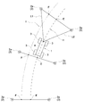
自動走行車両1を自動走行させる場合には、図8に示すように、車両側通信部12と左側に位置する走行位置特定用の無線情報タグ2aのタグ側通信部21との間で無線通信するとともに、車両側通信部12と右側に位置する障害物用の無線情報タグ2cのタグ側通信部21との間で無線通信する。これらの無線通信によって、走行制御部11は、距離検出部13による距離の検出、及び、方位検出部14による方位の検出に基づいて、左側の走行位置特定用の無線情報タグ2a及び右側の障害物用の無線情報タグ2cに対する自動走行車両1の相対位置を把握している。また、車両側通信部12と右側に位置する障害物用の無線情報タグ2cのタグ側通信部21との間で無線通信により、走行制御部11は、障害物用の無線情報タグ2cに記憶されている障害物情報R(図7参照)を取得しているので、障害物用の無線情報タグ2cに対する障害物Qの相対位置も把握している。これにより、走行制御部11は、左側の走行位置特定用の無線情報タグ2a及び右側の障害物用の無線情報タグ2cに対する自動走行車両1の相対位置、及び、障害物用の無線情報タグ2cに対する障害物Qの相対位置に基づいて、障害物Qを回避するための走行位置(走行経路)Uを特定しており、その走行位置Uを自動走行するように、自動走行車両1の走行を制御している。
図8に示すものでは、障害物Qを回避するための走行位置Uとして、左側の走行位置特定用の無線情報タグ2aと障害物Qにおける第3端部地点S3との間の中央地点Tを通過する走行位置Uが設定されている。走行位置Uは、左側の走行位置特定用の無線情報タグ2aと右側の障害物用の無線情報タグ2cとの間の走行位置Dから引き続いて自動走行車両1を自動走行させるための走行位置であり、障害物Qの存在位置よりも進行方向で手前箇所から、障害物Qが存在する分だけ、走行位置Dから左側に回避して走行させるようになっている。
このように、走行領域A内に障害物Qが存在しても、その障害物Qの存在位置に対応する位置に障害物用の無線情報タグ2cを配置しておくことで、走行制御部11は、障害物用の無線情報タグ2cに記憶されている障害物情報R(図7参照)を取得して、障害物Qを回避するように、自動走行車両1の走行を制御することができる。
障害物情報Rとして、図7では、障害物用の無線情報タグ2cに対する障害物Qの相対位置を、障害物用の無線情報タグ2cを基準点(ゼロ点)とするXY座標にて示した例を示したが、障害物情報Rをどのような形態で記憶させるかは適宜変更が可能である。
例えば、図9に示すように、上下方向及び左右方向に一定の所定間隔Wで複数のドットVを並べて配置したフィールドを備え、そのフィールド上において、障害物Qの存在位置をドットVの配置位置にて示すことも可能である。つまり、図9では、斜線にて示したドットVの配置位置にて囲む領域が障害物Qの存在位置となる。このとき、図9中上下方向が自動走行車両1の進行方向に沿う方向となっており、図9中左右方向が自動走行車両1の進行方向に直交する左右方向となっており、複数のドットVの並び方向と自動走行車両1の進行方向とが対応する状態で、障害物用の無線情報タグ2cに対する障害物Qの相対位置が示されている。
上述の如く、無線情報タグ2として、走行位置特定用の無線情報タグ2a、転回用の無線情報タグ2b、障害物用の無線情報タグ2c等の複数の無線情報タグ2を例示している。これらの無線情報タグ2a~2cは、何れも同様の構成を有する無線情報タグ2であり、タグ側記憶部22に記憶させる情報を異ならせることで、走行位置特定用の無線情報タグ2a、転回用の無線情報タグ2b、及び、障害物用の無線情報タグ2cの何れかの無線情報タグ2としている。
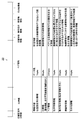
そこで、図11に基づいて、タグ側記憶部22に記憶させる情報のフォーマットの一例について説明する。図11では、タグ側記憶部22の記憶領域を上方側に示しており、各記憶領域に記憶されている情報を示す表を下方側に示している。位置固定用ID情報、ID情報、ペア情報、位置特徴情報、動作指示情報、障害物情報、その他情報の各情報を無線情報タグ2に対してライタ等により書き込むことで、タグ側記憶部22には、各情報が予め定められた記憶領域の夫々に記憶されている。
各情報について説明すると、位置固定用ID情報は、位置固定の無線情報タグ2であるという固有情報としており、この位置固定用ID情報は、配置位置が固定される無線情報タグ2に記憶されている。ID情報は、無線情報タグ2の固有情報であり、番地情報B及び走行不可能領域情報Cを含む情報としている。このID情報は、複数の無線情報タグ2の全てにおいて記憶されている。ペア情報は、自動走行車両1の進行方向に対して左右方向で一対のペアとなる無線情報タグ2との関係性を示す情報としており、ペア情報は、走行位置特定用の無線情報タグ2aに記憶されている。
位置特徴情報は、無線情報タグ2の配置位置がどのような位置に相当するのかを示す情報としている。位置特徴情報は、例えば、図1において、自動走行車両1を走行させる直線状の走行経路の途中部であることを示す情報、自動走行車両1を走行させる直線状の走行経路の端部であることを示す情報、及び、走行領域Aのコーナーであることを示す情報の何れかの情報としている。位置特徴情報は、ID情報と同様に、複数の無線情報タグ2の全てにおいて記憶させておくことができる。位置特徴情報が記憶されている無線情報タグ2を位置特徴用の無線情報タグ2としており、この実施形態では、走行位置特定用の無線情報タグ2a、転回用の無線情報タグ2b、障害物用の無線情報タグ2cの何れもが位置特徴用の無線情報タグ2とすることができる。
動作指示情報は、無線情報タグ2の配置位置で自動走行車両1をどのような動作を行うかを指示するための情報としている。動作位置情報は、例えば、自動走行車両1を転回走行させるための転回情報や、自動走行車両1を停止させるための情報としている。障害物情報Rは、図7及び図9に示すように、無線情報タグ2に対する障害物Qの相対位置を示す情報としており、障害物情報Rは、障害物用の無線情報タグ2cに記憶されている。その他情報は、無線情報タグ2の配置位置にて栽培されている作物の情報等、無線情報タグ2の配置位置において特有の情報としている。その他情報をどの無線情報タグ2に記憶されるかは適宜選択することができる。
このようにして、無線情報タグ2に記憶させる情報を異ならせることで、1つの無線情報タグ2を、走行位置特定用の無線情報タグ2aとして構成したり、転回用の無線情報タグ2bとして構成したり、障害物用の無線情報タグ2cとすることができる。また、1つの無線情報タグ2を、例えば、走行位置特定用の無線情報タグ2aと障害物用の無線情報タグ2cとして兼用することもできる。タグ側記憶部22に記憶されている情報を書き換え可能となっており、例えば、タグ側記憶部22に記憶されている情報を書き換えることで、走行位置特定用の無線情報タグ2aから転回用の無線情報タグ2bに変更させることもできる。
〔別実施形態〕
本発明の他の実施形態について説明する。
尚、以下に説明する各実施形態の構成は、夫々単独で適用することに限らず、他の実施形態の構成と組み合わせて適用することも可能である。
本発明の他の実施形態について説明する。
尚、以下に説明する各実施形態の構成は、夫々単独で適用することに限らず、他の実施形態の構成と組み合わせて適用することも可能である。
(1)上記実施形態では、果樹や作物を栽培する栽培列と重複するように複数の無線情報タグ2を配置しているが、複数の無線情報タグ2の配置位置については、自動走行車両1を自動走行させる走行位置(走行経路)に対応する位置であればよく、複数の無線情報タグ2をどのように配置させるかは適宜変更が可能である。
(2)上記実施形態において、自動走行車両1は、走行部3として複数の車輪を備えたものを例示したが、例えば、走行部3として、左右一対のクローラを備えるものとしてもよい。
(3)上記実施形態では、左右一対の走行位置特定用の無線情報タグ2aと車両側通信部12との通信により、左右一対の走行位置特定用の無線情報2aに対する自動走行車両1の相対位置を検出し、走行制御部11が、左右一対の走行位置特定用の無線情報2aに対する自動走行車両1の相対位置を用いて、中央地点E等を通過する走行位置(走行経路)Eを特定し、その走行位置Eを走行するように、自動走行車両1の走行を制御しているが、走行制御部11が、無線情報タグ2と車両側通信部12との通信によって検出される無線情報タグ2に対する自動走行車両1の相対位置を用いて、自動走行車両1の走行を制御するものであればよく、無線情報タグ2に対する自動走行車両1の相対位置を用いて、自動走行車両1をどのように制御するかは適宜変更が可能である。
例えば、1つの無線情報タグ2と車両側通信部12とが通信することで、その無線情報タグ2に対する自動走行車両1の相対位置を検出できるとともに、その無線情報タグ2に記憶されている走行不可能領域情報Cを取得することができる。そこで、走行制御部11は、自動走行車両1が進行方向を維持した状態で前進走行するように、自動走行車両1の走行を制御しておく。そして、自動走行車両1が走行不可能領域C1に侵入する可能性がある場合のみ、走行制御部11が、自動走行車両1の進行方向を変更させて、走行不可能領域C1を回避するように、自動走行車両1の走行を制御することができる。このような制御を行うことで、走行不可能領域C1への侵入を防止しながら、走行不可能領域C1の領域以外の領域において、自動走行車両1を前進走行させることができる。
本発明は、自動走行車両を自動走行させる各種の自動走行システムに適用できる。
1 自動走行車両
2 無線情報タグ
2a 走行位置特定用の無線情報タグ(位置特徴用の無線情報タグ)
2b 転回用の無線情報タグ(位置特徴用の無線情報タグ)
2c 障害物用の無線情報タグ(位置特徴用の無線情報タグ)
11 走行制御部
12 車両側通信部
13 距離検出部(相対位置検出部)
14 方位検出部(相対位置検出部)
J 転回情報
Q 障害物
R 障害物情報
2 無線情報タグ
2a 走行位置特定用の無線情報タグ(位置特徴用の無線情報タグ)
2b 転回用の無線情報タグ(位置特徴用の無線情報タグ)
2c 障害物用の無線情報タグ(位置特徴用の無線情報タグ)
11 走行制御部
12 車両側通信部
13 距離検出部(相対位置検出部)
14 方位検出部(相対位置検出部)
J 転回情報
Q 障害物
R 障害物情報
Claims (6)
- 所定位置に配置された複数の無線情報タグと、
自動走行車両に備えられ、前記無線情報タグとの間の通信を行う車両側通信部と、
前記無線情報タグと前記車両側通信部との間での通信により、前記無線情報タグに対する方位及び前記無線情報タグに対する距離を取得して前記無線情報タグに対する相対位置を検出する相対位置検出部と、
前記相対位置検出部にて検出される相対位置に基づいて、前記自動走行車両の走行を制御する走行制御部とが備えられている自動走行システム。 - 複数の無線情報タグは、前記自動走行車両の進行方向に対して左右方向に間隔を隔てて一対配置された走行位置特定用の無線情報タグを含み、
前記相対位置検出部は、一対の走行位置特定用の無線情報タグの夫々に対する相対位置を検出し、
前記走行制御部は、前記相対位置検出部にて検出される一対の走行位置特定用の無線情報タグの夫々に対する相対位置に基づいて、一対の走行位置特定用の無線情報タグの間を走行するように前記自動走行車両の走行を制御している請求項1に記載の自動走行システム。 - 前記走行制御部は、一対の走行位置特定用の無線情報タグの一方側に対する距離と他方側に対する距離との関係に応じて、前記自動走行車両の走行を制御することで、前記自動走行車両を、一対の走行位置特定用の無線情報タグの間を走行させる請求項2に記載の自動走行システム。
- 複数の無線情報タグは、その無線情報タグに対する障害物の相対位置を障害物情報として記憶している障害物用の無線情報タグを含み、
前記走行制御部は、前記障害物用の無線情報タグと前記車両側通信部との間での通信により取得される障害物情報に基づいて、障害物を回避するように前記自動走行車両の走行を制御している請求項1~3の何れか1項に記載の自動走行システム。 - 複数の無線情報タグは、前記自動走行車両を転回走行させる転回情報を記憶している転回用の無線情報タグを含み、
前記走行制御部は、前記転回用の無線情報タグと前記通信部との間での通信により取得される転回情報に基づいて、転回走行させるように前記自動走行車両の走行を制御している請求項1~4の何れか1項に記載の自動走行システム。 - 複数の無線情報タグは、自己の配置位置に関する位置特徴情報を記憶している位置特徴用の無線情報タグを含んでいる請求項1~5の何れか1項に記載の自動走行システム。
Priority Applications (1)
| Application Number | Priority Date | Filing Date | Title |
|---|---|---|---|
| EP18902412.8A EP3745232A4 (en) | 2018-01-26 | 2018-10-31 | AUTOMATIC DISPLACEMENT SYSTEM |
Applications Claiming Priority (2)
| Application Number | Priority Date | Filing Date | Title |
|---|---|---|---|
| JP2018011542A JP6854249B2 (ja) | 2018-01-26 | 2018-01-26 | 自動走行システム |
| JP2018-011542 | 2018-01-26 |
Publications (1)
| Publication Number | Publication Date |
|---|---|
| WO2019146202A1 true WO2019146202A1 (ja) | 2019-08-01 |
Family
ID=67395394
Family Applications (1)
| Application Number | Title | Priority Date | Filing Date |
|---|---|---|---|
| PCT/JP2018/040542 WO2019146202A1 (ja) | 2018-01-26 | 2018-10-31 | 自動走行システム |
Country Status (3)
| Country | Link |
|---|---|
| EP (1) | EP3745232A4 (ja) |
| JP (1) | JP6854249B2 (ja) |
| WO (1) | WO2019146202A1 (ja) |
Families Citing this family (2)
| Publication number | Priority date | Publication date | Assignee | Title |
|---|---|---|---|---|
| JP7427144B1 (ja) | 2022-10-03 | 2024-02-02 | フィブイントラロジスティクス株式会社 | 無人搬送車走行システム |
| WO2024075379A1 (ja) * | 2022-10-03 | 2024-04-11 | フィブイントラロジスティクス株式会社 | 無人搬送車走行システム |
Citations (8)
| Publication number | Priority date | Publication date | Assignee | Title |
|---|---|---|---|---|
| JP2004108782A (ja) * | 2002-09-13 | 2004-04-08 | Mitsubishi Heavy Ind Ltd | 保守点検システム及び保守点検方法 |
| JP2008092818A (ja) | 2006-10-06 | 2008-04-24 | Yanmar Co Ltd | 農用作業車 |
| JP2009259023A (ja) * | 2008-04-17 | 2009-11-05 | Panasonic Corp | 自走式機器およびそのプログラム |
| CN101957447A (zh) * | 2009-07-16 | 2011-01-26 | 北京石油化工学院 | 基于有源rfid的室内移动机器人定位系统和方法 |
| JP2011076215A (ja) * | 2009-09-29 | 2011-04-14 | Nec Personal Products Co Ltd | 自動走行ルートガイドツールおよび自動走行装置 |
| CN104834313A (zh) * | 2015-05-15 | 2015-08-12 | 济南大学 | 一种基于rfid的大棚智能喷药机器人及方法 |
| JP5987187B1 (ja) | 2015-10-16 | 2016-09-07 | Rfルーカス株式会社 | 記憶媒体位置検出システム及びプログラム |
| JP2017194764A (ja) * | 2016-04-19 | 2017-10-26 | 古屋製材株式会社 | 自動走行方法及びその方法を利用した自動走行運搬車並びに自動走行システム |
-
2018
- 2018-01-26 JP JP2018011542A patent/JP6854249B2/ja active Active
- 2018-10-31 WO PCT/JP2018/040542 patent/WO2019146202A1/ja unknown
- 2018-10-31 EP EP18902412.8A patent/EP3745232A4/en not_active Withdrawn
Patent Citations (8)
| Publication number | Priority date | Publication date | Assignee | Title |
|---|---|---|---|---|
| JP2004108782A (ja) * | 2002-09-13 | 2004-04-08 | Mitsubishi Heavy Ind Ltd | 保守点検システム及び保守点検方法 |
| JP2008092818A (ja) | 2006-10-06 | 2008-04-24 | Yanmar Co Ltd | 農用作業車 |
| JP2009259023A (ja) * | 2008-04-17 | 2009-11-05 | Panasonic Corp | 自走式機器およびそのプログラム |
| CN101957447A (zh) * | 2009-07-16 | 2011-01-26 | 北京石油化工学院 | 基于有源rfid的室内移动机器人定位系统和方法 |
| JP2011076215A (ja) * | 2009-09-29 | 2011-04-14 | Nec Personal Products Co Ltd | 自動走行ルートガイドツールおよび自動走行装置 |
| CN104834313A (zh) * | 2015-05-15 | 2015-08-12 | 济南大学 | 一种基于rfid的大棚智能喷药机器人及方法 |
| JP5987187B1 (ja) | 2015-10-16 | 2016-09-07 | Rfルーカス株式会社 | 記憶媒体位置検出システム及びプログラム |
| JP2017194764A (ja) * | 2016-04-19 | 2017-10-26 | 古屋製材株式会社 | 自動走行方法及びその方法を利用した自動走行運搬車並びに自動走行システム |
Non-Patent Citations (1)
| Title |
|---|
| See also references of EP3745232A4 |
Also Published As
| Publication number | Publication date |
|---|---|
| JP2019128882A (ja) | 2019-08-01 |
| JP6854249B2 (ja) | 2021-04-07 |
| EP3745232A4 (en) | 2021-12-15 |
| EP3745232A1 (en) | 2020-12-02 |
Similar Documents
| Publication | Publication Date | Title |
|---|---|---|
| EP2499546B1 (en) | Coordination of vehicle movement in a field | |
| WO2020256034A1 (ja) | 散布作業用の自動走行システム | |
| JP2018073050A (ja) | 走行経路生成装置 | |
| US20200356096A1 (en) | Autonomous agricultural working machine and method of operation | |
| JP7236887B2 (ja) | 経路生成システム | |
| WO2019146202A1 (ja) | 自動走行システム | |
| CN109564430A (zh) | 移动体引导系统、移动体、引导装置以及计算机程序 | |
| AU2017352853B2 (en) | Improvements to precision guidance system for agricultural vehicles | |
| KR20020068538A (ko) | 자주식 차량 | |
| DE102006004400A1 (de) | Navigationssystem, Vorrichtung und Navigationsverfahren | |
| JP7069002B2 (ja) | 圃場作業車及び圃場地図データ生成システム | |
| US20220382291A1 (en) | Route Generation Method, Route Generation Device, and Route Generation Program | |
| WO2020256036A1 (ja) | 作業車両 | |
| KR102405594B1 (ko) | 자율 이송로봇 | |
| JP7451481B2 (ja) | 農作業支援システム、自動走行車両の制御システム及び制御方法、並びにプログラム | |
| Matsuo et al. | Enhanced Adaptability of Tilling Robot (Initial Report)–Outline of a Tilling Robot and Enhanced Adaptability of Unmanned Operation– | |
| NL2031967B1 (en) | Indoor agricultural autonomous vehicle, system and method | |
| US20230001198A1 (en) | Method of controlling movement of hybrid robot and animal locomotion stimulation system thereof | |
| JP2022183963A (ja) | 散布作業方法、散布作業システム、及び散布作業プログラム | |
| TW202145875A (zh) | 載具系統 | |
| JP2021061015A (ja) | 経路生成システム | |
| Tang et al. | A control system of mobile navigation robot for precise spraying based ultrasonic detecting and ARM embedded technologies |
Legal Events
| Date | Code | Title | Description |
|---|---|---|---|
| 121 | Ep: the epo has been informed by wipo that ep was designated in this application |
Ref document number: 18902412 Country of ref document: EP Kind code of ref document: A1 |
|
| NENP | Non-entry into the national phase |
Ref country code: DE |
|
| ENP | Entry into the national phase |
Ref document number: 2018902412 Country of ref document: EP Effective date: 20200826 |