WO2019145998A1 - Générateur et son procédé de fonctionnement - Google Patents
Générateur et son procédé de fonctionnement Download PDFInfo
- Publication number
- WO2019145998A1 WO2019145998A1 PCT/JP2018/001974 JP2018001974W WO2019145998A1 WO 2019145998 A1 WO2019145998 A1 WO 2019145998A1 JP 2018001974 W JP2018001974 W JP 2018001974W WO 2019145998 A1 WO2019145998 A1 WO 2019145998A1
- Authority
- WO
- WIPO (PCT)
- Prior art keywords
- control circuit
- output
- generator
- circuit
- trigger
- Prior art date
Links
Images


Classifications
-
- A—HUMAN NECESSITIES
- A61—MEDICAL OR VETERINARY SCIENCE; HYGIENE
- A61B—DIAGNOSIS; SURGERY; IDENTIFICATION
- A61B17/00—Surgical instruments, devices or methods, e.g. tourniquets
- A61B17/32—Surgical cutting instruments
- A61B17/320068—Surgical cutting instruments using mechanical vibrations, e.g. ultrasonic
-
- A—HUMAN NECESSITIES
- A61—MEDICAL OR VETERINARY SCIENCE; HYGIENE
- A61B—DIAGNOSIS; SURGERY; IDENTIFICATION
- A61B18/00—Surgical instruments, devices or methods for transferring non-mechanical forms of energy to or from the body
- A61B18/04—Surgical instruments, devices or methods for transferring non-mechanical forms of energy to or from the body by heating
- A61B18/12—Surgical instruments, devices or methods for transferring non-mechanical forms of energy to or from the body by heating by passing a current through the tissue to be heated, e.g. high-frequency current
- A61B18/1206—Generators therefor
-
- A—HUMAN NECESSITIES
- A61—MEDICAL OR VETERINARY SCIENCE; HYGIENE
- A61B—DIAGNOSIS; SURGERY; IDENTIFICATION
- A61B17/00—Surgical instruments, devices or methods, e.g. tourniquets
- A61B17/32—Surgical cutting instruments
-
- A—HUMAN NECESSITIES
- A61—MEDICAL OR VETERINARY SCIENCE; HYGIENE
- A61B—DIAGNOSIS; SURGERY; IDENTIFICATION
- A61B18/00—Surgical instruments, devices or methods for transferring non-mechanical forms of energy to or from the body
- A61B18/04—Surgical instruments, devices or methods for transferring non-mechanical forms of energy to or from the body by heating
- A61B18/12—Surgical instruments, devices or methods for transferring non-mechanical forms of energy to or from the body by heating by passing a current through the tissue to be heated, e.g. high-frequency current
- A61B18/14—Probes or electrodes therefor
- A61B18/1402—Probes for open surgery
-
- A—HUMAN NECESSITIES
- A61—MEDICAL OR VETERINARY SCIENCE; HYGIENE
- A61B—DIAGNOSIS; SURGERY; IDENTIFICATION
- A61B17/00—Surgical instruments, devices or methods, e.g. tourniquets
- A61B2017/00017—Electrical control of surgical instruments
- A61B2017/00203—Electrical control of surgical instruments with speech control or speech recognition
-
- A—HUMAN NECESSITIES
- A61—MEDICAL OR VETERINARY SCIENCE; HYGIENE
- A61B—DIAGNOSIS; SURGERY; IDENTIFICATION
- A61B18/00—Surgical instruments, devices or methods for transferring non-mechanical forms of energy to or from the body
- A61B2018/00053—Mechanical features of the instrument of device
- A61B2018/00184—Moving parts
- A61B2018/0019—Moving parts vibrating
-
- A—HUMAN NECESSITIES
- A61—MEDICAL OR VETERINARY SCIENCE; HYGIENE
- A61B—DIAGNOSIS; SURGERY; IDENTIFICATION
- A61B18/00—Surgical instruments, devices or methods for transferring non-mechanical forms of energy to or from the body
- A61B2018/00571—Surgical instruments, devices or methods for transferring non-mechanical forms of energy to or from the body for achieving a particular surgical effect
- A61B2018/00607—Coagulation and cutting with the same instrument
-
- A—HUMAN NECESSITIES
- A61—MEDICAL OR VETERINARY SCIENCE; HYGIENE
- A61B—DIAGNOSIS; SURGERY; IDENTIFICATION
- A61B18/00—Surgical instruments, devices or methods for transferring non-mechanical forms of energy to or from the body
- A61B2018/00636—Sensing and controlling the application of energy
- A61B2018/00696—Controlled or regulated parameters
- A61B2018/00702—Power or energy
-
- A—HUMAN NECESSITIES
- A61—MEDICAL OR VETERINARY SCIENCE; HYGIENE
- A61B—DIAGNOSIS; SURGERY; IDENTIFICATION
- A61B18/00—Surgical instruments, devices or methods for transferring non-mechanical forms of energy to or from the body
- A61B2018/00636—Sensing and controlling the application of energy
- A61B2018/00773—Sensed parameters
- A61B2018/00845—Frequency
- A61B2018/00857—Frequency harmonic
-
- A—HUMAN NECESSITIES
- A61—MEDICAL OR VETERINARY SCIENCE; HYGIENE
- A61B—DIAGNOSIS; SURGERY; IDENTIFICATION
- A61B18/00—Surgical instruments, devices or methods for transferring non-mechanical forms of energy to or from the body
- A61B2018/00636—Sensing and controlling the application of energy
- A61B2018/00773—Sensed parameters
- A61B2018/00875—Resistance or impedance
-
- A—HUMAN NECESSITIES
- A61—MEDICAL OR VETERINARY SCIENCE; HYGIENE
- A61B—DIAGNOSIS; SURGERY; IDENTIFICATION
- A61B18/00—Surgical instruments, devices or methods for transferring non-mechanical forms of energy to or from the body
- A61B2018/00994—Surgical instruments, devices or methods for transferring non-mechanical forms of energy to or from the body combining two or more different kinds of non-mechanical energy or combining one or more non-mechanical energies with ultrasound
-
- A—HUMAN NECESSITIES
- A61—MEDICAL OR VETERINARY SCIENCE; HYGIENE
- A61B—DIAGNOSIS; SURGERY; IDENTIFICATION
- A61B18/00—Surgical instruments, devices or methods for transferring non-mechanical forms of energy to or from the body
- A61B18/04—Surgical instruments, devices or methods for transferring non-mechanical forms of energy to or from the body by heating
- A61B18/12—Surgical instruments, devices or methods for transferring non-mechanical forms of energy to or from the body by heating by passing a current through the tissue to be heated, e.g. high-frequency current
- A61B18/1206—Generators therefor
- A61B2018/1246—Generators therefor characterised by the output polarity
- A61B2018/1253—Generators therefor characterised by the output polarity monopolar
-
- A—HUMAN NECESSITIES
- A61—MEDICAL OR VETERINARY SCIENCE; HYGIENE
- A61B—DIAGNOSIS; SURGERY; IDENTIFICATION
- A61B90/00—Instruments, implements or accessories specially adapted for surgery or diagnosis and not covered by any of the groups A61B1/00 - A61B50/00, e.g. for luxation treatment or for protecting wound edges
- A61B90/06—Measuring instruments not otherwise provided for
- A61B2090/061—Measuring instruments not otherwise provided for for measuring dimensions, e.g. length
-
- A—HUMAN NECESSITIES
- A61—MEDICAL OR VETERINARY SCIENCE; HYGIENE
- A61B—DIAGNOSIS; SURGERY; IDENTIFICATION
- A61B90/00—Instruments, implements or accessories specially adapted for surgery or diagnosis and not covered by any of the groups A61B1/00 - A61B50/00, e.g. for luxation treatment or for protecting wound edges
- A61B90/06—Measuring instruments not otherwise provided for
- A61B2090/064—Measuring instruments not otherwise provided for for measuring force, pressure or mechanical tension
- A61B2090/065—Measuring instruments not otherwise provided for for measuring force, pressure or mechanical tension for measuring contact or contact pressure
Definitions
- the present invention relates to a generator and a method of operating the generator.
- an electric scalpel which supplies a high frequency current to a living tissue to be treated and coagulates or incises the living tissue.
- a technique for preventing a living tissue from sticking to the tip of the scalpel by vibrating an electrode which is the tip of the scalpel at a frequency in an ultrasonic region For example, U.S. Patent Application Publication 2009/0326569 discloses a technique for such a surgical tool. This document discloses determining whether the scalpel and the living tissue are in contact with each other based on the electrical impedance measured by flowing a high frequency current. Also, this document discloses that when it is determined that a contact is made, the output of high frequency current and the output of vibration are set to values set for treatment.
- the present invention aims to improve the functionality and ease of use of the surgical system.
- a generator for a surgical tool is configured to supply power to the ultrasonic transducer of a surgical tool for treating biological tissue comprising an ultrasonic transducer.
- Monitoring a first trigger leading to instructing to perform a resonant point scan of the oscillating system comprising the circuit and the probe and said ultrasound transducer and second leading to instructing treating the living tissue When the trigger is monitored and the first trigger is detected, resonance point scanning of the vibration system is performed to search for a resonance point, and when a resonance point is found, the ultrasonic transducer is maintained in the drive circuit so as to maintain resonance.
- the output operation for causing the drive circuit to supply power to the surgical instrument so that the surgical instrument treats the living tissue when the standby operation for causing the power to be supplied is performed and the second trigger is detected.
- at least one control circuit is configured to row.
- FIG. 1 is a view showing an outline of an example of an operation system according to an embodiment.
- FIG. 2 is a block diagram showing an outline of a configuration example of a surgical operation system according to an embodiment.
- FIG. 3 is a flow chart outlining an example of the operation of the surgical system according to one embodiment.
- FIG. 4 is a flow chart outlining an example of the operation of the first mode of the surgical system according to one embodiment.
- FIG. 5 is a timing chart for explaining the operation of the first mode of the surgery system according to an embodiment.
- FIG. 6 is a timing chart for explaining the operation of the second mode of the surgery system according to an embodiment.
- FIG. 7 is a flow chart outlining an example of the operation of the second mode of the surgical system according to one embodiment.
- FIG. 8 is a schematic view of a configuration example of a surgical instrument having a pressure sensor.
- FIG. 9 is a diagram schematically showing an example of the configuration of a surgical instrument having an optical distance sensor.
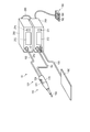
- FIG. 1 is a diagram showing an outline of the appearance of a surgery system 10 according to the present embodiment.
- the surgery system 10 is a system for treating a living tissue to be treated by high frequency current and ultrasonic vibration.
- the surgical system 10 has a function as a monopolar high frequency treatment tool.
- a probe as an electrode vibrates at a frequency in the ultrasonic region. Probe vibration is also utilized in the procedure.
- the surgical system 10 includes a surgical instrument 110, a return electrode plate 180, a foot switch 190, a first generator 200, and a second generator 300.
- the surgical instrument 110 includes an operation unit 120 and a probe 130.
- the operation unit 120 is a portion which the user holds and operates the surgical instrument 110.
- the probe 130 is provided at the tip of the operation unit 120.
- the probe 130 is applied to a living tissue to be treated at the time of treatment.
- the probe 130 functions as a high frequency electrode.
- a high frequency current flows from the probe 130 to the living tissue.
- the probe 130 is connected to an ultrasonic transducer provided in the operation unit 120. During the procedure, the probe 130 vibrates at a frequency in the ultrasound range.
- the operation unit 120 is provided with an output switch 121.
- the output switch 121 includes a first switch 122 and a second switch 124.
- the first switch 122 is a switch related to an input for operating the surgical instrument 110 in the incision mode.
- the dissection mode is a mode in which a living tissue to be treated is burnt at a portion in contact with the probe 130 by outputting a relatively large high frequency current.
- the second switch 124 is a switch related to an input for operating the surgical instrument 110 in the hemostasis mode. In the hemostasis mode, a weak high frequency current is output as compared to the incision mode. In the hemostasis mode, the probe 130 performs the hemostasis treatment by denaturing the end face of the living body tissue to be treated while burning it at the contacting portion.
- the return electrode plate 180 is attached to the body surface of the treatment subject.
- the current output from the probe 130 of the surgical instrument 110 is collected by the return electrode plate 180.
- the foot switch 190 comprises a first switch 192 and a second switch 194.
- the first switch 192 of the foot switch 190 has the same function as the first switch 122 provided on the surgical instrument 110.
- the second switch 194 of the foot switch 190 has the same function as the second switch 124 provided on the surgical instrument 110. That is, the user can switch on / off of the operation of the surgical tool 110 using the first switch 122 and the second switch 124 provided on the surgical tool 110, and the first of the foot switches 190 can be switched.
- the switch 192 and the second switch 194 can also be used to switch.
- the first generator 200 controls the operation of the surgical instrument 110.
- the first generator 200 outputs power for driving the ultrasonic transducer of the surgical instrument 110.
- the first generator 200 is connected to the surgical instrument 110 by a cable 152.
- the first generator 200 outputs power to the surgical instrument 110 via the cable 152.
- the first generator 200 is connected to the second generator 300 by a cable 290.
- the first generator 200 and the second generator 300 exchange necessary information via the cable 290.
- the first generator 200 includes a touch screen 272 as a user interface, an input unit 274, and a microphone 276.
- the touch screen 272 has, for example, a liquid crystal display (LCD) and a touch panel.
- the input unit 274 includes a button switch and the like.
- the first generator 200 may obtain an instruction from the user using the touch screen 272, the input unit 274, and the microphone 276.
- the first generator 200 may use the touch screen 272 to present information to the user.
- the second generator 300 controls the operation of the surgical instrument 110.
- the second generator 300 outputs power so as to cause current to flow between the probe 130 of the surgical tool 110 and the return electrode plate 180.
- the second generator 300 is connected to the surgical instrument 110 by a cable 154.
- the second generator 300 is connected to the return electrode plate 180 by a cable 156.
- the second generator 300 includes a touch screen 372 as a user interface and an input unit 374.
- the touch screen 372 has, for example, a liquid crystal display (LCD) and a touch panel.
- the input unit 374 includes a button switch and the like.
- the second generator 300 may obtain an instruction from the user using the touch screen 372 and the input unit 374.
- the second generator 300 can use the touch screen 372 to present information to the user.
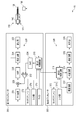
- FIG. 2 is a block diagram showing an outline of a configuration example of the surgery system 10.
- the surgical instrument 110 is provided with an ultrasonic transducer 140.
- the ultrasonic transducer 140 includes a plurality of piezoelectric elements. Each of the piezoelectric elements is sandwiched by electrodes of different polarities.
- the ultrasonic transducer 140 is formed by laminating these piezoelectric elements.
- the ultrasonic transducer 140 vibrates at the frequency when an AC voltage of a frequency in the ultrasonic region is applied from the first generator 200. This vibration is transmitted to the probe 130.
- the first generator 200 comprises a first control circuit 210.
- the first control circuit 210 controls the operation of each part of the first generator 200.
- the first control circuit 210 includes an integrated circuit such as, for example, a central processing unit (CPU), an application specific integrated circuit (ASIC), or a field programmable gate array (FPGA).
- the first control circuit 210 may be configured of one integrated circuit or the like, or may be configured by combining a plurality of integrated circuits or the like.
- the operation of the first control circuit 210 is performed, for example, in accordance with a program or the like recorded in a storage circuit or a storage area inside the control circuit.
- the first control circuit 210 acquires input signals to the output switch 121 of the surgical tool 110, the touch screen 272 of the first generator 200, the input unit 274, the microphone 276, and the like.
- the first control circuit 210 also controls display on the touch screen 272.
- the first generator 200 includes a drive circuit 220.
- the drive circuit 220 is a circuit for driving the ultrasonic transducer 140. That is, the drive circuit 220 is a circuit that generates a voltage to be applied to the electrode of the ultrasonic transducer 140.
- the first generator 200 of this embodiment employs a PLL control method as a resonance tracking method. Further, the first generator 200 employs a constant current control method as an amplitude control method.
- the Drive circuit 220 includes a transformer 222.
- the transformer 222 boosts and outputs a necessary voltage.
- the output of the transformer 222 is input to the ultrasonic transducer 140.
- the transformer 222 also plays a role of preventing a current of a direct current component from flowing between the circuit of the first generator 200 and the circuit of the surgical instrument 110.
- the circuit of the surgical instrument 110 is a circuit in contact with the patient.
- the circuit of the first generator 200 is a circuit connected to a commercial power supply.
- the drive circuit 220 includes a detection circuit 224, a power amplifier 226, a voltage control amplifier 228, a phase locked loop (PLL) circuit 230, a differential amplifier 232, and a DA converter (DAC) 234.
- PLL phase locked loop
- DAC DA converter
- the output of the voltage control amplifier 228 is input to the power amplifier 226.
- the power amplifier 226 amplifies the output of the voltage control amplifier 228 and adjusts the signal input to the transformer 222.
- the detection circuit 224 detects the voltage and current input from the power amplifier 226 to the primary coil of the transformer 222 and their phases.
- the PLL circuit 230 is a circuit for tracking the resonance frequency of the ultrasonic transducer 140.
- the PLL circuit 230 performs resonance tracking using the voltage phase signal detected by the detection circuit 224 and the current phase signal.
- the PLL circuit 230 performs resonance tracking by performing control to bring the phase difference between the voltage and the current close to zero.
- the output of PLL circuit 230 is input to voltage control amplifier 228.
- the voltage control amplifier 228 is a multiplier.
- the signal from the differential amplifier 232 is input to the voltage control amplifier 228.
- the differential amplifier 232 compares the signal of the current magnitude obtained from the detection circuit 224 with the signal from the DAC 234.
- the DAC 234 inputs a signal related to the magnitude of the output from the first control circuit 210 to the ultrasonic transducer 140 to the differential amplifier 232.
- the first control circuit 210 detects that the power switch is turned on. At this time, the first control circuit 210 outputs a digital signal relating to the target value of the size of the output to the ultrasonic transducer 140 to the DAC 234.
- the DAC 234 converts the signal input from the first control circuit 210 into an analog signal, and outputs the converted signal to the differential amplifier 232.
- the signal from the DAC 234 and the signal from the detection circuit 224 are input to the differential amplifier 232.
- Differential amplifier 232 compares the signal from DAC 234 with the signal from detection circuit 224. That is, the differential amplifier 232 compares the control signal indicating the target value of the output output from the first control circuit 210 with the current output detected by the detection circuit 224.
- the differential amplifier 232 outputs the comparison result to the voltage control amplifier 228.
- Voltage control amplifier 228 multiplies the input from PLL circuit 230 by the input from differential amplifier 232. As a result, the output voltage is adjusted to the magnitude instructed by the first control circuit 210. Therefore, a signal whose resonance is tracked by PLL circuit 230 and whose output is adjusted to a magnitude based on the control signal of first control circuit 210 using voltage control amplifier 228 and differential amplifier 232 is power.
- the signal is input to the amplifier 226.
- the power amplifier 226 amplifies the signal and outputs it to the transformer 222.
- the transformer 222 boosts the input voltage and supplies power to the ultrasonic transducer 140. Thus, appropriate energy supply to the ultrasonic transducer 140 is performed. As a result, the ultrasonic transducer 140 vibrates.
- the second generator 300 comprises a second control circuit 310.
- the second control circuit 310 controls the operation of each part of the second generator 300.
- the second control circuit 310 includes an integrated circuit such as, for example, a central processing unit (CPU), an application specific integrated circuit (ASIC), or a field programmable gate array (FPGA).
- the second control circuit 310 may be configured of one integrated circuit or the like, or may be configured by combining a plurality of integrated circuits or the like.
- the operation of the second control circuit 310 is performed, for example, according to a program or the like recorded in a memory circuit or a memory area inside the control circuit.
- the second control circuit 310 obtains input signals to the output switch 121 of the surgical tool 110, the touch screen 372 of the second generator 300, the input unit 374 and the like.
- the second control circuit 310 also controls display on the touch screen 372.
- the first control circuit 210 of the first generator 200 and the second control circuit 310 of the second generator 300 are connected.
- the first control circuit 210 of the first generator 200 and the second control circuit 310 of the second generator 300 exchange necessary information.
- the second generator 300 comprises an output circuit 320.
- the output circuit 320 is a circuit that applies a high frequency voltage between the probe 130 of the surgical instrument 110 and the return electrode plate 180.
- the output circuit 320 includes a power supply circuit 322, a resonant circuit 324, a detection circuit 326, and a transformer 328.
- the power supply circuit 322 is, for example, a DC / DC converter.
- the second control circuit 310 turns on the output of the power supply circuit 322 based on the fact that the output switch 121 of the surgical instrument 110 is turned on. At this time, the second control circuit 310 controls the magnitude of the output of the power supply circuit 322.
- the DC voltage output from the power supply circuit 322 is supplied to the resonance circuit 324.
- the resonance circuit 324 converts the DC voltage supplied from the power supply circuit 322 into an AC voltage under the control of the second control circuit 310.
- the resonant circuit 324 inputs the generated AC voltage to the primary coil of the transformer 328 through the detection circuit 326.
- the detection circuit 326 detects, for example, the voltage applied to the primary coil of the transformer 328 and the current flowing through the primary coil.
- the detection circuit 326 transmits the detection result to the second control circuit 310.
- the second control circuit 310 controls the output of the power supply circuit 322 using the detection result of the detection circuit 326.
- the transformer 328 boosts the output voltage of the resonant circuit 324.
- the transformer 328 applies a boosted voltage between the probe 130 of the surgical instrument 110 and the return electrode plate 180.
- the transformer 328 also plays a role of preventing a current of a DC component from flowing between the circuit of the second generator 300 and the circuit of the surgical instrument 110.
- the circuit of the surgical instrument 110 is a circuit in contact with the patient.
- the circuit of the second generator 300 is a circuit to which a commercial power supply is connected.
- the user brings the probe 130 into contact with the living tissue to be treated, and turns on the output switch 121.
- the surgical instrument 110 outputs energy.
- the first control circuit 210 of the first generator 200 acquires information indicating that the output switch 121 is turned on.
- the first control circuit 210 causes the drive circuit 220 to output power for driving the ultrasonic transducer 140.
- the ultrasonic transducer 140 vibrates due to this output power. This vibration is transmitted and the probe 130 vibrates.
- the second control circuit 310 of the second generator 300 causes the output circuit 320 to output high frequency power. As a result, a high frequency current flows in the living tissue located between the probe 130 and the return electrode plate 180.
- a PLL is used to resonate a vibration system including the ultrasonic transducer 140 and the probe 130 at a frequency in the ultrasonic region.
- some time is required to generate resonance in a PLL. Therefore, in order to simultaneously output high frequency power while the probe 130 is in resonance, it is necessary to output high frequency power after the resonance of the probe 130 is realized.
- the first mode is a mode in which the resonance of the probe 130 is realized in advance before the output switch 121 is pressed.
- the second mode is a mode in which the resonance of the probe 130 is first realized after the output switch 121 is pressed, and then the output of high frequency power is performed.
- step S101 the first control circuit 210 of the first generator 200 determines whether the currently set mode is the first mode or the second mode.
- the output mode is previously selected by the user at the start of use, for example, by an input using the touch screen 272 of the first generator 200.
- an example in which either the first mode or the second mode is set by the first generator 200 and the setting is determined by the first control circuit 210 of the first generator 200 is shown.
- the setting and determination may be performed by the second generator 300 without being limited thereto.
- step S102 When the first mode is selected, the process proceeds to step S102, and the treatment of the first mode is performed.
- the process proceeds to step S103, and the process of the second mode is performed. After the operation in each mode, the process proceeds to step S104.
- step S104 the first control circuit 210 of the first generator 200 determines whether to end the process. For example, when the power of the first generator 200 is turned off, it is determined to end. If not, the process returns to step S101. On the other hand, when the process ends, the present process ends.
- the process of the first mode will be described with reference to the flowchart shown in FIG.
- the first mode is a mode in which the resonance of the probe 130 is realized in advance before the output switch 121 is pressed.
- the output switch 121 is pressed, the vibration of the treatment probe 130 and the output of high frequency power are simultaneously started.
- step S201 the first control circuit 210 of the first generator 200 performs a standby required detection process to determine whether standby is required.
- standby refers to a state in which the resonance of the probe 130 is maintained. When the standby is necessary, it shifts to the standby state.
- a criterion determined to require standby is referred to as a first trigger.
- the probe 130 when the probe 130 is in contact with a living tissue, it is determined that the standby is necessary. Whether or not the probe 130 and the living tissue are in contact with each other can be determined, for example, by obtaining a value reflecting the electrical impedance between the probe 130 and the return electrode 180.
- the impedance between the probe 130 and the return electrode 180 connected to the living tissue is relatively low.
- the second generator 300 applies a weak current between the probe 130 and the return electrode plate 180, and obtains a value related to the impedance between the probe 130 and the return electrode plate 180.
- the second control circuit 310 transmits this value to the first control circuit 210 of the first generator 200.
- the first control circuit 210 of the first generator 200 performs a standby required detection process based on the received value.
- the first trigger is that the impedance between the probe 130 and the return electrode plate 180 is less than a predetermined value.
- step S202 the first control circuit 210 determines whether to start the standby state based on the processing result of step S201. When in the standby state, the process proceeds to step S203. In step S203 and subsequent steps, a standby operation is performed.
- the standby operation includes performing resonance point scanning of the vibration system in response to the detection of the first trigger to search for a resonance point, and maintaining the resonance of the vibration system if a resonance point is found.
- the first control circuit 210 causes the drive circuit 220 to perform resonance point search.
- the output of the drive circuit 220 is adjusted to a low level, and the probe 130 is slightly vibrated by the ultrasonic transducer 140.
- the first control circuit 210 gradually changes the output frequency, for example, from high frequency to low frequency.
- the first control circuit 210 analyzes the phase difference between the voltage and current detected by the detection circuit 224 at this time. At the resonance point of the vibration system including the ultrasonic transducer 140 and the probe 130, the phase difference between the voltage and the current disappears. At the resonance point, the current easily flows.
- the first control circuit 210 performs a resonance point scan that determines a resonance point based on the phase of the voltage and the current while gradually changing the output frequency from, for example, a high frequency to a low frequency. In addition, since the current easily flows and the amplitude increases when the resonance point is found, the first control circuit 210 adjusts the current value to an appropriate range so as to appropriately suppress the amplitude. If a resonance point is found, the process proceeds to step S204.
- step S204 the first control circuit 210 causes the drive circuit 220 to perform a resonance point maintaining operation.
- the resonance point maintaining operation the ultrasonic transducer 140 continues vibrating at a low output, and PLL processing continues to be performed. Because the output level is low, the vibration amplitude of the probe 130 is also small. Therefore, even if the probe 130 comes in contact with the living tissue, the living tissue is not treated by this contact.
- step S205 the first control circuit 210 performs a standby required detection process as in step S201.
- step S206 the first control circuit 210 determines whether to maintain the standby state.
- the output to the ultrasonic transducer 140 is stopped, and the process returns to step S201.
- the standby state is not maintained.
- the first trigger is released, the power supply to the ultrasonic transducer 140 is stopped.
- the process proceeds to step S207.
- step S207 the first control circuit 210 determines whether the output switch 121 is on. If the output switch 121 is not on, the process returns to step S204. That is, resonance is maintained while the standby state is to be maintained. On the other hand, when it is determined that the output switch 121 is on, the process proceeds to step S208.
- step S208 the surgery system 10 performs the main output operation in the first mode. That is, the first control circuit 210 of the first generator 200 raises the output of the drive circuit 220 to a necessary level so that the probe 130 vibrates at an amplitude suitable for treatment. Also at this time, the resonance of the probe 130 is continuously maintained. As a result, the probe 130 vibrates with a sufficiently large amplitude.
- the second control circuit 310 of the second generator 300 makes the output of the output circuit 320 an output necessary for treatment with a high frequency current. As a result, a high frequency current flows from the probe 130 to the living tissue. The high frequency current and the vibration of the probe 130 treat the living tissue.
- the criteria that lead to the treatment of living tissue will be referred to as the second trigger. Turning on the output switch 121 is a second trigger. Similarly, turning on the foot switch 190 is also a second trigger.
- step S209 the first control circuit 210 of the first generator 200 determines whether the output switch 121 is off. If the output is not turned off and the on state continues, the process returns to step S208. That is, this output is maintained, the probe 130 vibrates with a large amplitude, and a high frequency current flows from the probe 130 to the living tissue. Even when the probe 130 and the living tissue are separated, this output is maintained while the output switch 121 is on.
- step S210 the surgery system 10 stops the output.
- step S210 the first control circuit 210 of the first generator 200 determines whether to end the processing of the first mode. When it is determined to end, the process ends. For example, when the treatment is finished and the power is turned off, the process ends. Further, when the mode switching operation is performed from the menu screen and the mode is switched from the first mode to the second mode, the present process ends. On the other hand, when it is determined that the process does not end, the process returns to step S201. That is, the above process is repeated.
- each part in the first mode will be described with reference to the timing chart shown in FIG. It is assumed that standby is required at time t1. Here, the output switch 121 remains off. At this time, resonance point search is performed at low output. It is assumed that a resonance point is found at time t2. Even after time t2, the output for driving the ultrasonic transducer 140 of the drive circuit 220 is maintained at a low output for maintaining resonance.
- the output switch 121 is turned on at time t3. At this time, the output for driving the ultrasonic transducer 140 of the drive circuit 220 is set to a high output. Also, the output of the output circuit 320 is set to a high output, and the output of high frequency power is started. At time t4, when the output switch 121 is turned off, the output of the drive circuit 220 is stopped and the vibration of the ultrasonic transducer 140 is stopped. Further, the output of the output circuit 320 is stopped, and the output of high frequency power is stopped.
- step S202 If it is determined in step S202 that standby is not to be started, the process proceeds to step S211.
- step S211 the first control circuit 210 of the first generator 200 determines whether the output switch 121 is on. If the output switch 121 is not on, the process returns to step S201. That is, the above process is repeated. On the other hand, when it is determined that the output switch 121 is on, the process proceeds to step S212.
- step S212 the surgery system 10 performs this output.
- the main output is performed in the second mode.
- step S213 the first control circuit 210 of the first generator 200 determines whether the output switch 121 is turned off. When the output switch 121 is not turned off and the on state is maintained, the process returns to step S212, and this output is maintained. On the other hand, when the output switch 121 is turned off, the process proceeds to step S210.
- each part in the second mode will be described with reference to the timing chart shown in FIG. It is assumed that the output switch 121 is turned on at time t5. At this time, resonance point search is performed at low output. Assume that a resonance point is found at time t6. At this time, the output for driving the ultrasonic transducer 140 of the drive circuit 220 is set to a high output. Also, the output of the output circuit 320 is set to a high output, and the output of high frequency power is started.
- Switching of the drive circuit 220 to a high output and start of the output of the output circuit 320 may be performed based on a lock signal indicating that a resonance point has been found and resonated. That is, such a lock signal is output from the first control circuit 210 of the first generator 200 to the second control circuit 310 of the second generator 300.
- the second control circuit 310 may start output of high frequency power when the lock signal is received.
- the time required for the past resonance point search may be stored and used. That is, switching of the drive circuit 220 to high output and start of output of the output circuit 320 may be performed after the time has elapsed since the output switch 121 was turned on.
- the probe 130 As described above, in the first mode, it is determined whether standby is necessary.
- a standby state such as when the living tissue comes in contact
- resonance point search is performed, and resonance is maintained while the standby state is to be maintained.
- the output switch 121 As soon as the output switch 121 is turned on, the ultrasonic wave output and the high frequency output are simultaneously started.
- the output switch 121 is turned on while not in the standby state, resonance point search is first performed, and as soon as a resonance point is found, ultrasonic wave output and high frequency output are simultaneously started.
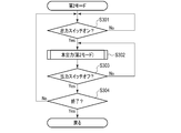
- step S103 The operation of the second mode performed in step S103 will be described with reference to the flowchart shown in FIG.
- step S301 the first control circuit 210 of the first generator 200 determines whether the output switch 121 is on. If the output switch 121 is not on, the process returns to step S301. That is, it waits until the output switch 121 is turned on. On the other hand, when it is determined that the output switch 121 is on, the process proceeds to step S302.
- step S302 the surgery system 10 performs the main output in the second mode described above.
- step S303 the first control circuit 210 of the first generator 200 determines whether the output switch 121 is turned off. When the output switch 121 is not turned off and the on state is maintained, the process returns to step S302, and this output is maintained. On the other hand, when the output switch 121 is turned off, the process proceeds to step S304.
- step S304 the first control circuit 210 of the first generator 200 determines whether to end the present process. When it is determined to end, the process ends. On the other hand, when it is determined that the process does not end, the process returns to step S301. That is, the above process is repeated.
- no output is required before the output switch 121 is turned on.
- an output for grasping the contact state between the probe 130 and the living tissue is not necessary.
- the vibration of the probe 130 is delayed with respect to the output of the high frequency power, the effect of preventing the sticking of the tissue to the probe 130 by the vibration can not be obtained while the high frequency power is output alone.
- the vibration of the probe 130 at the ultrasonic frequency and the output of the high frequency power are adjusted to start at the same time.
- the resonance point search is performed in advance so that the output is performed immediately when the user turns on the output switch 121.
- the surgical system 10 is sophisticated and easy to use.
- the contact state between the probe 130 and the return electrode 180 may be determined based on the value of the output voltage or the output current.
- changes in various electrical parameters can be the first trigger.
- a pressure sensor 171 that senses that the probe 130 is in contact with the living tissue 900 may be provided on the surgical instrument 110.
- the position where the pressure sensor 171 is disposed may be any position at which the contact pressure between the probe 130 and the living tissue can be detected.
- the contact pressure is detected, for example, by pushing the probe 130 proximally.
- the first control circuit 210 of the first generator 200 can acquire the detection result of the pressure sensor 171 and can determine whether the probe 130 is in contact with the living tissue 900. When in contact, the first control circuit 210 can determine that a standby state is required.
- the pressure sensor is an example, and various dynamic sensors such as a strain sensor may be used as well.
- an optical distance sensor capable of measuring the distance to an object present in the direction of the tip of the probe 130 may be used.
- the surgical instrument 110 is provided with a light emitting unit 174 that emits, for example, infrared light in the direction of the tip of the probe 130 and a light receiving unit 175 that detects light reflected by the biological tissue 900 or the like. It may be done.
- the first control circuit 210 of the first generator 200 can acquire the detection result of such an optical distance sensor, and acquire the distance between the tip of the probe 130 and an object such as the living tissue 900.
- the first control circuit 210 can determine that the standby state is necessary when the distance between the tip of the probe 130 and the object is less than a predetermined value.
- the tip of the probe 130 and the object may not necessarily be in contact with each other.
- the distance between the tip of the probe 130 and the object may be specified based on the image obtained by capturing the tip of the probe 130.
- the first control circuit 210 acquires an image of the tip of the probe 130.
- the first control circuit 210 performs image processing on this image to specify the distance between the probe 130 and the living tissue.
- the first control circuit 210 may determine whether a standby state is necessary based on the identification result of the distance.
- the first control circuit 210 may monitor a first trigger based on image information.
- a switch for switching to the standby state may be provided.
- the output switch 121 is a two-stage switch and the first stage switch is turned on, the standby state is established, and when the second stage switch is turned on, this output is performed. It may be configured. In this case, the presence or absence of standby may be set by the user using the user interface.
- the first generator 200 may be configured to allow the user to instruct by voice to put on standby.
- the microphone 276 picks up the sound, and the first control circuit 210 performs speech recognition processing.
- the first control circuit 210 may determine whether the user desires the standby state based on the voice recognition result.
- the first control circuit 210 may monitor a first trigger based on audio information.
- the determination as to whether or not the standby state is necessary can be made based on various information.
- the division of roles between the first control circuit 210 of the first generator 200 and the second control circuit 310 of the second generator 300 in the surgery system 10 of the above-described embodiment is an example. Any control circuit may play any role.
- the first generator 200 and the second generator 300 may be integrated, and the number of control circuits may be one.
- the output of the surgical instrument 110 is a combination of the output of the high frequency power and the vibration at the frequency in the ultrasonic region, but it is not limited thereto.
- the surgical tool may, for example, treat living tissue only by vibration.
- the surgical instrument may be, for example, a surgical instrument provided with a heater at the tip of the probe 130. In this case, the surgical instrument uses a combination of heat output by the heater and vibration at a frequency in the ultrasonic range. Again, it may be configured and function the same as the embodiments described above.
Abstract
Cette invention concerne un générateur (200) pour outil chirurgical (110) comprenant un circuit d'attaque (220) et un circuit de commande (210). Le circuit d'attaque (220) est conçu pour alimenter un vibreur à ultrasons (140) de l'outil chirurgical (110). Le circuit de commande (210) surveille un premier déclencheur qui amène à une instruction d'exécution de balayage des points de résonance d'un système de vibration, et surveille un second déclencheur qui amène à une instruction de traitement d'un tissu corporel. Lors de la détection du premier déclencheur, le circuit de commande (210) recherche un point de résonance par balayage des points de résonance du système de vibration et provoque l'exécution d'une opération en veille pour maintenir la résonance, et lors de la détection du second déclencheur, provoque l'exécution d'une opération de sortie formelle où l'outil chirurgical (110) traite le tissu corporel.
Priority Applications (2)
| Application Number | Priority Date | Filing Date | Title |
|---|---|---|---|
| PCT/JP2018/001974 WO2019145998A1 (fr) | 2018-01-23 | 2018-01-23 | Générateur et son procédé de fonctionnement |
| US16/936,088 US20200345407A1 (en) | 2018-01-23 | 2020-07-22 | Generator and operation method thereof |
Applications Claiming Priority (1)
| Application Number | Priority Date | Filing Date | Title |
|---|---|---|---|
| PCT/JP2018/001974 WO2019145998A1 (fr) | 2018-01-23 | 2018-01-23 | Générateur et son procédé de fonctionnement |
Related Child Applications (1)
| Application Number | Title | Priority Date | Filing Date |
|---|---|---|---|
| US16/936,088 Continuation US20200345407A1 (en) | 2018-01-23 | 2020-07-22 | Generator and operation method thereof |
Publications (1)
| Publication Number | Publication Date |
|---|---|
| WO2019145998A1 true WO2019145998A1 (fr) | 2019-08-01 |
Family
ID=67395897
Family Applications (1)
| Application Number | Title | Priority Date | Filing Date |
|---|---|---|---|
| PCT/JP2018/001974 WO2019145998A1 (fr) | 2018-01-23 | 2018-01-23 | Générateur et son procédé de fonctionnement |
Country Status (2)
| Country | Link |
|---|---|
| US (1) | US20200345407A1 (fr) |
| WO (1) | WO2019145998A1 (fr) |
Citations (4)
| Publication number | Priority date | Publication date | Assignee | Title |
|---|---|---|---|---|
| JP2007537013A (ja) * | 2004-05-14 | 2007-12-20 | メドトロニック・インコーポレーテッド | 高密度焦点式超音波を使用してアブレートした組織領域を形成する方法 |
| JP2008036390A (ja) * | 2006-08-09 | 2008-02-21 | Olympus Medical Systems Corp | 中継ユニット及び超音波手術・高周波焼灼装置 |
| JP2010005370A (ja) * | 2008-06-26 | 2010-01-14 | Olympus Medical Systems Corp | 外科手術システム |
| WO2014034224A1 (fr) * | 2012-08-31 | 2014-03-06 | オリンパスメディカルシステムズ株式会社 | Système de chirurgie ultrasonore |
Family Cites Families (13)
| Publication number | Priority date | Publication date | Assignee | Title |
|---|---|---|---|---|
| US5026387A (en) * | 1990-03-12 | 1991-06-25 | Ultracision Inc. | Method and apparatus for ultrasonic surgical cutting and hemostatis |
| EP1715810B1 (fr) * | 2005-01-18 | 2012-05-09 | Alma Lasers Ltd | Systeme ameliore de chauffage de tissus biologiques par de l'energie rf |
| US8308721B2 (en) * | 2008-12-04 | 2012-11-13 | Olympus Medical Systems Corp. | Surgical system and surgical method |
| US20100331833A1 (en) * | 2009-06-26 | 2010-12-30 | Michael Maschke | In-vitro device monitoring during minimally invasive ablation therapy |
| US9161803B2 (en) * | 2010-11-05 | 2015-10-20 | Ethicon Endo-Surgery, Inc. | Motor driven electrosurgical device with mechanical and electrical feedback |
| WO2012174161A1 (fr) * | 2011-06-14 | 2012-12-20 | Aerin Medical, Inc. | Dispositifs pour le traitement des voies respiratoires nasales |
| CN103826561B (zh) * | 2011-09-20 | 2016-04-27 | 奥林巴斯株式会社 | 手术系统 |
| US20130197404A1 (en) * | 2012-01-27 | 2013-08-01 | Avner Spector | Method for imporoving kidney function with extracorporeal shockwaves |
| US10610289B2 (en) * | 2013-09-25 | 2020-04-07 | Covidien Lp | Devices, systems, and methods for grasping, treating, and dividing tissue |
| US10610306B2 (en) * | 2013-12-09 | 2020-04-07 | Intuitive Surgical Operations, Inc. | Systems and methods for device-aware flexible tool registration |
| CN106793968A (zh) * | 2014-10-13 | 2017-05-31 | 波士顿科学医学有限公司 | 使用微电极的组织诊断和治疗 |
| US20160324531A1 (en) * | 2015-05-05 | 2016-11-10 | Rainbow Medical Ltd. | Sinus treatment |
| CN113729627A (zh) * | 2016-05-02 | 2021-12-03 | 阿弗拉公司 | 导管感应以及冲洗 |
-
2018
- 2018-01-23 WO PCT/JP2018/001974 patent/WO2019145998A1/fr active Application Filing
-
2020
- 2020-07-22 US US16/936,088 patent/US20200345407A1/en active Pending
Patent Citations (4)
| Publication number | Priority date | Publication date | Assignee | Title |
|---|---|---|---|---|
| JP2007537013A (ja) * | 2004-05-14 | 2007-12-20 | メドトロニック・インコーポレーテッド | 高密度焦点式超音波を使用してアブレートした組織領域を形成する方法 |
| JP2008036390A (ja) * | 2006-08-09 | 2008-02-21 | Olympus Medical Systems Corp | 中継ユニット及び超音波手術・高周波焼灼装置 |
| JP2010005370A (ja) * | 2008-06-26 | 2010-01-14 | Olympus Medical Systems Corp | 外科手術システム |
| WO2014034224A1 (fr) * | 2012-08-31 | 2014-03-06 | オリンパスメディカルシステムズ株式会社 | Système de chirurgie ultrasonore |
Also Published As
| Publication number | Publication date |
|---|---|
| US20200345407A1 (en) | 2020-11-05 |
Similar Documents
| Publication | Publication Date | Title |
|---|---|---|
| CA2813385C (fr) | Dispositifs et techniques de coupe et de coagulation de tissus | |
| JP5722215B2 (ja) | 階段状の出力で切断及び凝固するための超音波装置 | |
| US8808286B2 (en) | Surgical system | |
| US20100168742A1 (en) | Surgical operation system and surgical operation method | |
| EP1609428A1 (fr) | Appareil de traitement par ultrason avec des modes de traitement selectionnables | |
| US8292883B2 (en) | Electrosurgical apparatus and method of controlling electrosurgical apparatus | |
| JP2008036390A (ja) | 中継ユニット及び超音波手術・高周波焼灼装置 | |
| WO2019145998A1 (fr) | Générateur et son procédé de fonctionnement | |
| JP4291377B2 (ja) | 超音波手術装置および超音波手術装置の制御方法 | |
| JP6095878B1 (ja) | 高周波処置具のための電源装置、高周波処置システム、及び高周波処置システムの作動方法 | |
| US20200121380A1 (en) | Treatment system | |
| JPH0538343A (ja) | 超音波駆動装置 | |
| JPH03131245A (ja) | 超音波処置装置 | |
| US20170245918A1 (en) | Power supply device for high frequency treatment instrument, high frequency treatment system, and control method for high frequency treatment instrument | |
| WO2018016016A1 (fr) | Appareil de commande d'énergie et système de traitement | |
| JPH05212048A (ja) | 手術装置 | |
| US20190038338A1 (en) | Power Supply Device for High-Frequency Treatment Tool, High-Frequency Treatment System, and Method of Controlling High-Frequency Treatment Tool | |
| US20190038339A1 (en) | Power Supply Device for High-Frequency Treatment Tool, High-Frequency Treatment System, and Method of Controlling High-Frequency Treatment Tool | |
| WO2020183737A1 (fr) | Dispositif de commande, système de traitement par ultrasons et procédé de sondage de fréquence de résonance | |
| US8206382B2 (en) | Surgical apparatus with sensor for obtaining states of surgical instrument information | |
| JP2001238893A (ja) | 超音波手術装置 | |
| AU2015227493B2 (en) | Ultrasonic device for cutting and coagulating with stepped output | |
| JPH0956726A (ja) | 電気手術装置 | |
| JP2004057497A (ja) | 超音波処置装置 |
Legal Events
| Date | Code | Title | Description |
|---|---|---|---|
| 121 | Ep: the epo has been informed by wipo that ep was designated in this application |
Ref document number: 18902778 Country of ref document: EP Kind code of ref document: A1 |
|
| NENP | Non-entry into the national phase |
Ref country code: DE |
|
| 122 | Ep: pct application non-entry in european phase |
Ref document number: 18902778 Country of ref document: EP Kind code of ref document: A1 |
|
| NENP | Non-entry into the national phase |
Ref country code: JP |