WO2019138827A1 - 物体認識装置 - Google Patents
物体認識装置 Download PDFInfo
- Publication number
- WO2019138827A1 WO2019138827A1 PCT/JP2018/046921 JP2018046921W WO2019138827A1 WO 2019138827 A1 WO2019138827 A1 WO 2019138827A1 JP 2018046921 W JP2018046921 W JP 2018046921W WO 2019138827 A1 WO2019138827 A1 WO 2019138827A1
- Authority
- WO
- WIPO (PCT)
- Prior art keywords
- camera control
- image
- control value
- sign
- unit
- Prior art date
- Legal status (The legal status is an assumption and is not a legal conclusion. Google has not performed a legal analysis and makes no representation as to the accuracy of the status listed.)
- Ceased
Links
Images


Classifications
-
- G—PHYSICS
- G08—SIGNALLING
- G08G—TRAFFIC CONTROL SYSTEMS
- G08G1/00—Traffic control systems for road vehicles
- G08G1/09—Arrangements for giving variable traffic instructions
- G08G1/0962—Arrangements for giving variable traffic instructions having an indicator mounted inside the vehicle, e.g. giving voice messages
- G08G1/09623—Systems involving the acquisition of information from passive traffic signs by means mounted on the vehicle
-
- G—PHYSICS
- G06—COMPUTING OR CALCULATING; COUNTING
- G06T—IMAGE DATA PROCESSING OR GENERATION, IN GENERAL
- G06T7/00—Image analysis
-
- G—PHYSICS
- G06—COMPUTING OR CALCULATING; COUNTING
- G06T—IMAGE DATA PROCESSING OR GENERATION, IN GENERAL
- G06T7/00—Image analysis
- G06T7/80—Analysis of captured images to determine intrinsic or extrinsic camera parameters, i.e. camera calibration
-
- H—ELECTRICITY
- H04—ELECTRIC COMMUNICATION TECHNIQUE
- H04N—PICTORIAL COMMUNICATION, e.g. TELEVISION
- H04N7/00—Television systems
- H04N7/18—Closed-circuit television [CCTV] systems, i.e. systems in which the video signal is not broadcast
Definitions
- the present invention relates to an object recognition apparatus.
- the types of road signs include signboard-type road signs, LED-type electric signs installed on expressways, etc., and internal lighting signs that emit light internally at night, and the road sign recognition function uses these various types of road signs It is required to be recognized.
- Patent Document 1 as a method of recognizing a non-luminous signboard sign and an LED-type electric sign, an image is always captured using two types of exposure, and a candidate is selected based on the variation of the luminance distribution of the candidate area.
- a road sign recognition device is disclosed that determines whether the sign in the area is a non-luminous signboard sign or an LED sign.
- Patent Document 1 Although two types of exposure are always performed in Patent Document 1, there is no exposure that can be imaged in a state in which three types of markers can be recognized, and the number of imaging times of each marker when two types of exposure are always performed Decreases. Since the recognition performance of a road sign depends on the number of times of imaging of the sign, there is a problem that the recognition performance is degraded.
- An object of the present invention is to provide an object recognition apparatus capable of suppressing a decrease in the number of times of imaging and improving a recognition rate in view of such a problem.
- a camera control unit that calculates a camera control value that controls the brightness of an image, and an image that captures an image based on the camera control value calculated by the camera control unit.
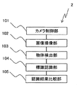
- FIG. 1 It is a functional block diagram showing composition of an object recognition device concerning Embodiment 1 of the present invention. It is a flowchart which shows an example of operation
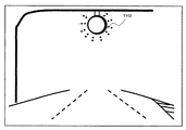
- FIG. 3 It is a figure showing the road where the speed limit sign of an interior illumination type was installed. It is the image which imaged the road shown in FIG. 3 by the camera control value calculated on the basis of a road surface etc.
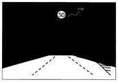
- FIG. 3 It is the image which picturized the road shown in Drawing 3 with the camera control value which can picturize the darker image than the camera control value computed on the basis of a road surface etc.
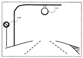
- FIG. 6 It is the image which picturized the road shown in Drawing 6 by the camera control value which can picturize the image darker than the camera control value computed on the basis of a road surface etc.
- FIG. 2 It is a functional block diagram which shows the structure of the object recognition apparatus which concerns on Embodiment 2 of this invention. It is a flowchart which shows an example of operation
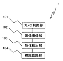
- FIG. 1 is a functional block showing the configuration of the object recognition device 1 of the first embodiment.
- FIG. 2 is a flowchart showing an example of the operation of the object recognition device 1 of FIG.
- the object recognition apparatus 1 recognizes the signs (a signboard sign, an internal illumination sign, etc.) from which a brightness
- the object recognition device 1 of the present embodiment is configured by a computer (processor), a memory, a storage device, and the like, and the computer operates as various functional units by executing a control program stored in the memory or the like.
- the object recognition apparatus 1 has a camera control unit 101 as a functional unit realized by the operation of a computer, an image pickup unit 102, an object detection unit 103, and a sign recognition unit 104.
- the camera control unit 101 calculates a camera control value for controlling the brightness of the camera (image) and outputs the calculated value to the image capturing unit 102.
- the camera control value corresponds to the exposure time of the camera, the analog gain value, the F value of the lens, and the like. In addition, you may change F value using a filter.
- the camera control value may be calculated based on the brightness of the road surface, or the camera control value may be calculated based on the brightness of the sky area.
- the case of using the brightness of the road surface as a reference will be described, but the present invention is not limited.
- the image capturing unit 102 acquires a camera control value (camera control amount) from the camera control unit 101, and captures an image by reflecting the control value on the camera. That is, the image capturing unit 102 captures an image of the brightness adjusted using the acquired camera control value. In other words, the image capturing unit 102 captures an image based on the camera control value calculated by the camera control unit 101.
- the captured image is output to the object detection unit 103.
- the object detection unit 103 detects a predetermined object in the image captured by the image capturing unit 102, and outputs the detection result to the camera control unit 101.
- a circular high-brightness object is described as a predetermined object, but the present invention is not limited thereto.
- it may be a polygon (triangle, square, etc.) high luminance object.
- a circular shape is used as a control sign for speed limit and the like.
- the object detection unit 103 detects, for example, a high-brightness object (predetermined object) having a brightness higher than that of the LED-type electric light marker. This makes it possible to detect an object as a candidate for the internal illumination marker.
- Hough transform may be performed to identify a candidate area including a circular object, and then detection may be performed based on the high brightness pixel ratio in the specified candidate area.
- the camera control unit 101 adjusts a camera control value. Specifically, when a high brightness object is detected by the object detection unit 103, a camera control value is calculated in which the image becomes darker than the previous camera control value. At this time, the camera control unit 101 may continuously calculate a camera control value that makes the image darker as a camera control value to be calculated later, or a camera control value that makes the image darker and a camera control value that makes the image brighter May be calculated alternately.
- the sign recognition unit 104 performs a process of recognizing a road sign from the image captured by the image capturing unit 102.
- recognition processing of the road sign when the position of the road sign in the image is specified, template matching processing using the sign template image of the recognition target is performed to the specified position, and the sign is correlated with the highly correlated sign template image.
- the acquired road sign type and the sign information indicated on the road sign are acquired.
- the type of road sign and the sign information indicated on the road sign may be acquired by a statistical method using machine learning based on a large number of images obtained by photographing the road sign.
- the output of the marker recognition unit 104 may be a marker type identified by a template matching process or a statistical method, or an identification score expressing marker likeliness at the time of identification. The identification score will be described later using Tables 1 and 2.
- the marker recognition unit 104 may select an object to be recognized according to the camera control value calculated by the camera control unit 101. Specifically, as a means for recognizing a road sign, a low-brightness signboard marker is capable of capturing a bright image and a high-brightness internal light sign is recognized as a camera control value capable of capturing a dark image. When template matching is used, the template itself to be used is limited to the mark to be recognized (for example, a signboard sign etc.).
- the sign recognition unit 104 selectively recognizes a road sign of a sign type (a signboard sign, an LED-type electric light sign, an interior illumination sign or the like) according to the camera control value calculated by the camera control unit 101. For example, matching processing is performed on a camera control value for capturing a bright image using a template of a signboard sign, and matching processing is performed on a camera control value for capturing a dark image using a template for an internal illumination label. Thereby, the processing time of template matching can be shortened, and a road sign can be recognized at high speed.
- the correspondence between the camera control value and the marker type is stored, for example, in a storage device such as a memory.
- the object recognition device 1 calculates a camera control value based on a road surface or the like (S101), and carries out image capturing based on the calculated camera control value (S102).
- the camera control unit 101 calculates a camera control value (first camera control value) as a reference of the brightness of the image before a circular high-brightness object (predetermined object) is detected.
- the calculated camera control value is temporarily stored, for example, in a storage device such as a memory.
- a circular high-intensity object is detected from the captured image (S103), and a road sign recognition process is performed (S104).
- a camera control value for capturing an image darker than the previously captured image is calculated as a subsequent exposure control value (S106), and The imaging (S107) and the road sign recognition process are performed (S108). If a circular high luminance object is not detected (S105: NO), the previous camera control value is calculated as the subsequent exposure control value.
- the camera control unit 101 makes the image darker than before the high brightness circular object is detected.
- a camera control value (second camera control value) is calculated (S106).
- S106 for example, a dark image is captured by shortening the exposure time, reducing the analog gain value, or the like, and it is possible to suppress overexposure.
- the camera control unit 101 adjusts the camera control value. Thereby, the brightness of the image can be switched as needed.
- a camera control value for capturing an image darker than the previously captured image as a subsequent camera control value.
- a camera control value capable of capturing a bright image and a camera control value capable of capturing a dark image may be alternately calculated.
- the camera control unit 101 calculates the same camera control value as the camera control value (first camera control value) calculated in S101 and S106.
- the same camera control value (second camera control value) and the same camera control value may be calculated alternately.
- FIG. 4 shows an image of the traveling environment of FIG. 3 captured by a camera control value based on the road surface.
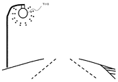
- T101 in FIG. 3 represents an internally illuminated speed limit sign
- T102 in FIG. 4 represents an internally illuminated speed limit sign imaged in an overexposed state on the image.
- the object recognition apparatus 1 detects T102 as a circular high brightness object from the image shown in FIG. 4 (S105: YES), and captures an image darker than the previously captured image as a camera control value thereafter. A camera control value is calculated (S106), and an image is captured (S107).
- FIG. T103 in FIG. 5 An image captured by the camera control value calculated in S106 is shown in FIG. T103 in FIG. 5 indicates an internally illuminated speed limit sign. Since the camera control value calculated in S106 can capture a dark image, it is possible to suppress overexposure of the internal illumination marker.
- the object recognition apparatus 1 detects a state in which the internal illumination marker which is imaged in a state of overexposure with an exposure control amount calculated on the basis of a road surface or the like and in which recognition is difficult is overexposed.
- image capture using a camera control value capable of capturing a dark image, it is possible to suppress overexposure and to recognize an internal illumination marker.
- a dark image can be captured only when an internal illumination marker appears, using a camera control value capable of capturing a bright image calculated on the basis of a road surface or the like.
- the brightness of the image can be adaptively switched with respect to the appearing sign, the decrease in the number of times of imaging of the sign is suppressed, and the improvement of the recognition rate is expected. That is, the number of times of imaging the marker increases and the recognition rate of the marker increases as compared with the prior art.
- the recognition rate of the sign and the like decreases as the vehicle speed increases, according to the present embodiment, the probability that the sign and the like can be recognized increases even if the vehicle speed increases.
- FIG. 6 shows an operation example of the object recognition device 1 when the vehicle travels the road shown in FIG. 6 .
- a low brightness billboard sign and a high brightness internal illumination sign are provided.
- FIG. 7 shows an image of the traveling environment of FIG. 6 captured by a camera control value based on the road surface.
- T104 in FIG. 6 indicates a signboard-type no-parking sign
- T105 indicates an internally illuminated speed limit sign
- T106 in FIG. 7 represents a signboard-type parking prohibition sign that has been captured
- T107 represents an internally illuminated speed limit sign that has been captured in an overexposed state.
- the object recognition apparatus 1 detects T107 as a circular high brightness object from the image shown in FIG. 7 (S103). Next, T104 is recognized as a road sign as follows (S108).
- FIG. 8 shows an image captured with a camera control value capable of capturing an image darker than the camera control value before the high brightness object is detected.
- T109 in FIG. 8 indicates an internally illuminated speed limit sign.
- the camera control value calculated in S106 is an image that is darker than the camera control value obtained by capturing the image shown in FIG. 7, so it is possible to suppress overexposure of the internal illumination marker.
- the sign-type parking prohibition sign described in T108 is blacked out.
- FIG. 9 shows functional blocks of this embodiment.
- the parts corresponding to those in FIG. 1 are indicated by the same reference numerals (101 to 104).
- FIG. 10 is a flowchart showing an example of the operation of the object recognition device 2 of FIG.
- the object recognition apparatus 1 of this embodiment distinguishes a circular-shaped high-intensity object and a internally illuminated sign like a street lamp so that it may mention later.
- the recognition result comparison unit 105 compares the recognition results of the sign recognition unit 104 with the images captured based on different camera control values, and transmits the comparison result to the camera control unit 101. Specifically, the recognition result of the sign recognition unit 104 with respect to the image captured based on the camera control value calculated based on the road surface or the like, and the object detection unit 103 detects a predetermined object, and the camera control value is adjusted. The recognition result of the sign recognition unit 104 with respect to the image (dark image) is compared.
- the camera control unit 101 calculates the previous camera control value as a camera control value.
- the object recognition device 2 calculates a camera control value based on a road surface or the like (S201), and carries out image capturing based on the calculated camera control value (S202).
- a circular high luminance object is detected from the captured image (S203), and a road sign recognition process is performed (S204).
- a camera control value for capturing an image darker than the previously captured image is calculated as a subsequent camera control value (S206), and The image capture (S207) and the road sign recognition process are performed (S208). If a circular high brightness object is not detected (S205: NO), the previous camera control value is calculated as the subsequent camera control value.
- a marker recognition result (S204) for an image captured based on a camera control value calculated on the basis of a road surface or the like, and an image (dark image) in which a circular high brightness object is detected and the camera control value is adjusted. are compared with the recognition result (S208) for (S209).
- the camera control value for capturing a dark image is calculated as the subsequent camera control value, and the amount of change in the two recognition results is a predetermined value If it is less than (S210: NO), the previous camera control value is calculated as the subsequent camera control value (S212).
- the camera control unit 101 calculates the camera control value calculated in S206 when the change amount of the recognition result is equal to or more than the predetermined value (S210: YES). The same camera control value as (second camera control value) is calculated (S212). In addition, the camera control unit 101 calculates the camera control value (first camera control value) calculated in S201 when the amount of change in the recognition result is less than the predetermined value after the circular high brightness object (predetermined object) is detected. The same camera control value as the control value is calculated (S212).
- the change amount of the recognition result is equal to or more than a predetermined value, and when the circular high brightness object is a street lamp, the change amount of the recognition result is less than the predetermined value.
- T110 of FIG. 11 has shown the street lamp installed on the road.
- the object recognition device 2 detects T110 as a circular high-brightness object from the traveling environment shown in FIG. 11 (S203), and carries out a marker recognition process (S204). As the subsequent camera control values, a camera control value for capturing an image darker than the previously captured image is calculated (S206), and the image is captured (S207).
- the second column of Table 1 shows the identification score (value: 3) expressing the marker likeness of the marker recognition process (S204), and the third column shows the identification score (value: 4) of the marker recognition process (S208) It shows.
- the higher the value the higher the mark-like identification score.
- the identification score for images captured with different camera control values does not change significantly (S210: NO).
- the object recognition device 2 detects T101 as a circular high-brightness object from the traveling environment shown in FIG. 3 (S203), and carries out a marker recognition process (S204). As the subsequent camera control values, a camera control value for capturing an image darker than the previously captured image is calculated (S206), and the image is captured (S207).
- the internal illumination marker is imaged in an overexposed state on the image imaged in S202, but since the image imaged in S207 is a dark image, it is imaged in a state in which the contrast ratio of the internal pattern is high.
- the discrimination score of the marker recognition processing tends to increase as the contrast ratio of the pattern increases, so the discrimination score of S208 is higher and the discrimination score changes significantly compared to the discrimination score in S204.
- the object recognition apparatus is, for example, a stereo camera, but the number of imaging devices (image capturing units) is arbitrary, and may be a monocular camera.
- each of the configurations, functions, and the like described above may be realized by hardware by designing part or all of them, for example, by an integrated circuit.
- each configuration, function, and the like described above may be realized by software by a computer (processor) interpreting and executing a program that realizes each function.
- Information such as a program, a table, and a file for realizing each function can be placed in a memory, a hard disk, a recording device such as an SSD (Solid State Drive), or a recording medium such as an IC card, an SD card, or a DVD.
- the embodiment of the present invention may have the following aspects.
- a camera control unit that calculates a camera control value that controls the brightness of an image, an image pickup unit that picks up an image based on the camera control value of the camera control unit, and a predetermined image among images picked up by the image pickup unit
- An object recognition apparatus comprising: an object detection unit that detects an object; and the camera control unit adjusts the camera control amount when the predetermined object is detected by the object detection unit.
- the camera control unit is characterized in that when the predetermined object is detected in the object detection unit, a camera control value in which an image becomes darker than a previous control value is calculated (1) to (3).
- the object recognition device according to any one of the above.
- the camera control unit is configured such that, when the predetermined object is detected by the object detection unit, an image is compared with a camera control value in which the image is dark with respect to the previous control value and a camera control value in which the image is dark.
- the image processing unit further includes a sign recognition unit that recognizes a road sign in an image captured by the image capturing unit, and the sign recognition unit selects a sign type to be recognized based on a camera control value of the camera control unit.
- the device further includes a marker recognition result comparison unit that compares the recognition result of the marker recognition unit with an image captured using a control amount, and the predetermined object is detected when the change amount of the recognition result is a predetermined value or more.
Landscapes
- Engineering & Computer Science (AREA)
- Physics & Mathematics (AREA)
- General Physics & Mathematics (AREA)
- Computer Vision & Pattern Recognition (AREA)
- Theoretical Computer Science (AREA)
- Multimedia (AREA)
- Signal Processing (AREA)
- Traffic Control Systems (AREA)
- Image Analysis (AREA)
- Closed-Circuit Television Systems (AREA)
Priority Applications (1)
| Application Number | Priority Date | Filing Date | Title |
|---|---|---|---|
| DE112018005708.9T DE112018005708T5 (de) | 2018-01-12 | 2018-12-20 | Objekterkennungsvorrichtung |
Applications Claiming Priority (2)
| Application Number | Priority Date | Filing Date | Title |
|---|---|---|---|
| JP2018-003460 | 2018-01-12 | ||
| JP2018003460A JP6868932B2 (ja) | 2018-01-12 | 2018-01-12 | 物体認識装置 |
Publications (1)
| Publication Number | Publication Date |
|---|---|
| WO2019138827A1 true WO2019138827A1 (ja) | 2019-07-18 |
Family
ID=67219650
Family Applications (1)
| Application Number | Title | Priority Date | Filing Date |
|---|---|---|---|
| PCT/JP2018/046921 Ceased WO2019138827A1 (ja) | 2018-01-12 | 2018-12-20 | 物体認識装置 |
Country Status (3)
| Country | Link |
|---|---|
| JP (1) | JP6868932B2 (https=) |
| DE (1) | DE112018005708T5 (https=) |
| WO (1) | WO2019138827A1 (https=) |
Cited By (1)
| Publication number | Priority date | Publication date | Assignee | Title |
|---|---|---|---|---|
| JPWO2022157886A1 (https=) * | 2021-01-21 | 2022-07-28 |
Families Citing this family (2)
| Publication number | Priority date | Publication date | Assignee | Title |
|---|---|---|---|---|
| US12585842B2 (en) | 2019-09-13 | 2026-03-24 | Yoshiteru TOKUYAMA | Information processing device, program, and information processing method |
| JP7277666B2 (ja) | 2020-03-03 | 2023-05-19 | 日立Astemo株式会社 | 処理装置 |
Citations (3)
| Publication number | Priority date | Publication date | Assignee | Title |
|---|---|---|---|---|
| JP2010026591A (ja) * | 2008-07-15 | 2010-02-04 | Panasonic Corp | 標識認識装置及び標識認識方法 |
| JP2013147112A (ja) * | 2012-01-18 | 2013-08-01 | Fuji Heavy Ind Ltd | 車両の走行環境認識装置 |
| JP2014160408A (ja) * | 2013-02-20 | 2014-09-04 | Denso Corp | 道路標識認識装置 |
Family Cites Families (2)
| Publication number | Priority date | Publication date | Assignee | Title |
|---|---|---|---|---|
| JP5747549B2 (ja) * | 2011-02-18 | 2015-07-15 | 株式会社豊田中央研究所 | 信号機検出装置及びプログラム |
| KR101353052B1 (ko) * | 2013-07-31 | 2014-01-20 | 주식회사 피엘케이 테크놀로지 | 교통표지판 인식을 위한 차량용 영상인식시스템 |
-
2018
- 2018-01-12 JP JP2018003460A patent/JP6868932B2/ja active Active
- 2018-12-20 DE DE112018005708.9T patent/DE112018005708T5/de active Pending
- 2018-12-20 WO PCT/JP2018/046921 patent/WO2019138827A1/ja not_active Ceased
Patent Citations (3)
| Publication number | Priority date | Publication date | Assignee | Title |
|---|---|---|---|---|
| JP2010026591A (ja) * | 2008-07-15 | 2010-02-04 | Panasonic Corp | 標識認識装置及び標識認識方法 |
| JP2013147112A (ja) * | 2012-01-18 | 2013-08-01 | Fuji Heavy Ind Ltd | 車両の走行環境認識装置 |
| JP2014160408A (ja) * | 2013-02-20 | 2014-09-04 | Denso Corp | 道路標識認識装置 |
Cited By (3)
| Publication number | Priority date | Publication date | Assignee | Title |
|---|---|---|---|---|
| JPWO2022157886A1 (https=) * | 2021-01-21 | 2022-07-28 | ||
| WO2022157886A1 (ja) * | 2021-01-21 | 2022-07-28 | 日本電気株式会社 | パラメータ最適化システム、パラメータ最適化方法、及びコンピュータプログラム |
| JP7509245B2 (ja) | 2021-01-21 | 2024-07-02 | 日本電気株式会社 | パラメータ最適化システム、パラメータ最適化方法、及びコンピュータプログラム |
Also Published As
| Publication number | Publication date |
|---|---|
| JP6868932B2 (ja) | 2021-05-12 |
| DE112018005708T5 (de) | 2020-07-23 |
| JP2019125022A (ja) | 2019-07-25 |
Similar Documents
| Publication | Publication Date | Title |
|---|---|---|
| JP4766302B2 (ja) | 画像処理装置および方法、記録媒体、並びにプログラム | |
| CN105453153B (zh) | 交通灯检测 | |
| CN104951745B (zh) | 车外环境识别装置 | |
| JPWO2006109398A1 (ja) | 画像処理装置および方法、プログラム、並びに記録媒体 | |
| JP2012226513A (ja) | 検知装置、及び検知方法 | |
| KR20210006276A (ko) | 플리커를 약화시키기 위한 이미지 처리 방법 | |
| CN113723304B (zh) | 车灯检测方法、装置、电子设备及存储介质 | |
| EP1962226A2 (en) | Image recognition device for vehicle and vehicle head lamp controller and method of controlling head lamps | |
| CN110033425B (zh) | 干扰区域检测装置及方法、电子设备 | |
| CN103679733A (zh) | 一种信号灯图像处理方法及其装置 | |
| CN111027494A (zh) | 一种基于计算机视觉的矩阵车灯识别方法 | |
| JP5065172B2 (ja) | 車両灯火判定装置及びプログラム | |
| WO2019138827A1 (ja) | 物体認識装置 | |
| JP7289723B2 (ja) | 物体認識装置 | |
| CN106971185A (zh) | 一种基于全卷积网络的车牌定位方法及装置 | |
| JP5481074B2 (ja) | 照明環境判定装置及びプログラム | |
| JP2010152900A (ja) | 画像処理装置及び画像処理プログラム | |
| JP2010286995A (ja) | 車両用画像処理システム | |
| JP7114965B2 (ja) | ターゲット検出方法、装置及び画像処理装置 | |
| JP6723537B2 (ja) | 信号機認識装置、信号認識システム、及び信号機認識方法 | |
| JP6034713B2 (ja) | 車外環境認識装置および車外環境認識方法 | |
| KR102793534B1 (ko) | 역광 검출장치 및 방법 | |
| JP7277666B2 (ja) | 処理装置 | |
| CN114387179B (zh) | 图像的处理方法、装置、存储介质和电子设备 | |
| CN114945234A (zh) | 一种路灯的ai智能配光调节方法、装置及路灯 |
Legal Events
| Date | Code | Title | Description |
|---|---|---|---|
| 121 | Ep: the epo has been informed by wipo that ep was designated in this application |
Ref document number: 18899394 Country of ref document: EP Kind code of ref document: A1 |
|
| 122 | Ep: pct application non-entry in european phase |
Ref document number: 18899394 Country of ref document: EP Kind code of ref document: A1 |