WO2019137375A1 - 送风组件、送风系统及冰箱 - Google Patents
送风组件、送风系统及冰箱 Download PDFInfo
- Publication number
- WO2019137375A1 WO2019137375A1 PCT/CN2019/070868 CN2019070868W WO2019137375A1 WO 2019137375 A1 WO2019137375 A1 WO 2019137375A1 CN 2019070868 W CN2019070868 W CN 2019070868W WO 2019137375 A1 WO2019137375 A1 WO 2019137375A1
- Authority
- WO
- WIPO (PCT)
- Prior art keywords
- air
- air supply
- duct cover
- wind wheel
- disposed
- Prior art date
Links
Images


Classifications
-
- F—MECHANICAL ENGINEERING; LIGHTING; HEATING; WEAPONS; BLASTING
- F25—REFRIGERATION OR COOLING; COMBINED HEATING AND REFRIGERATION SYSTEMS; HEAT PUMP SYSTEMS; MANUFACTURE OR STORAGE OF ICE; LIQUEFACTION SOLIDIFICATION OF GASES
- F25D—REFRIGERATORS; COLD ROOMS; ICE-BOXES; COOLING OR FREEZING APPARATUS NOT OTHERWISE PROVIDED FOR
- F25D17/00—Arrangements for circulating cooling fluids; Arrangements for circulating gas, e.g. air, within refrigerated spaces
- F25D17/04—Arrangements for circulating cooling fluids; Arrangements for circulating gas, e.g. air, within refrigerated spaces for circulating air, e.g. by convection
- F25D17/06—Arrangements for circulating cooling fluids; Arrangements for circulating gas, e.g. air, within refrigerated spaces for circulating air, e.g. by convection by forced circulation
- F25D17/062—Arrangements for circulating cooling fluids; Arrangements for circulating gas, e.g. air, within refrigerated spaces for circulating air, e.g. by convection by forced circulation in household refrigerators
- F25D17/065—Arrangements for circulating cooling fluids; Arrangements for circulating gas, e.g. air, within refrigerated spaces for circulating air, e.g. by convection by forced circulation in household refrigerators with compartments at different temperatures
-
- F—MECHANICAL ENGINEERING; LIGHTING; HEATING; WEAPONS; BLASTING
- F25—REFRIGERATION OR COOLING; COMBINED HEATING AND REFRIGERATION SYSTEMS; HEAT PUMP SYSTEMS; MANUFACTURE OR STORAGE OF ICE; LIQUEFACTION SOLIDIFICATION OF GASES
- F25D—REFRIGERATORS; COLD ROOMS; ICE-BOXES; COOLING OR FREEZING APPARATUS NOT OTHERWISE PROVIDED FOR
- F25D21/00—Defrosting; Preventing frosting; Removing condensed or defrost water
- F25D21/14—Collecting or removing condensed and defrost water; Drip trays
-
- F—MECHANICAL ENGINEERING; LIGHTING; HEATING; WEAPONS; BLASTING
- F25—REFRIGERATION OR COOLING; COMBINED HEATING AND REFRIGERATION SYSTEMS; HEAT PUMP SYSTEMS; MANUFACTURE OR STORAGE OF ICE; LIQUEFACTION SOLIDIFICATION OF GASES
- F25D—REFRIGERATORS; COLD ROOMS; ICE-BOXES; COOLING OR FREEZING APPARATUS NOT OTHERWISE PROVIDED FOR
- F25D17/00—Arrangements for circulating cooling fluids; Arrangements for circulating gas, e.g. air, within refrigerated spaces
- F25D17/04—Arrangements for circulating cooling fluids; Arrangements for circulating gas, e.g. air, within refrigerated spaces for circulating air, e.g. by convection
- F25D17/06—Arrangements for circulating cooling fluids; Arrangements for circulating gas, e.g. air, within refrigerated spaces for circulating air, e.g. by convection by forced circulation
- F25D17/067—Evaporator fan units
-
- F—MECHANICAL ENGINEERING; LIGHTING; HEATING; WEAPONS; BLASTING
- F25—REFRIGERATION OR COOLING; COMBINED HEATING AND REFRIGERATION SYSTEMS; HEAT PUMP SYSTEMS; MANUFACTURE OR STORAGE OF ICE; LIQUEFACTION SOLIDIFICATION OF GASES
- F25D—REFRIGERATORS; COLD ROOMS; ICE-BOXES; COOLING OR FREEZING APPARATUS NOT OTHERWISE PROVIDED FOR
- F25D2317/00—Details or arrangements for circulating cooling fluids; Details or arrangements for circulating gas, e.g. air, within refrigerated spaces, not provided for in other groups of this subclass
- F25D2317/06—Details or arrangements for circulating cooling fluids; Details or arrangements for circulating gas, e.g. air, within refrigerated spaces, not provided for in other groups of this subclass with forced air circulation
- F25D2317/063—Details or arrangements for circulating cooling fluids; Details or arrangements for circulating gas, e.g. air, within refrigerated spaces, not provided for in other groups of this subclass with forced air circulation with air guides
-
- F—MECHANICAL ENGINEERING; LIGHTING; HEATING; WEAPONS; BLASTING
- F25—REFRIGERATION OR COOLING; COMBINED HEATING AND REFRIGERATION SYSTEMS; HEAT PUMP SYSTEMS; MANUFACTURE OR STORAGE OF ICE; LIQUEFACTION SOLIDIFICATION OF GASES
- F25D—REFRIGERATORS; COLD ROOMS; ICE-BOXES; COOLING OR FREEZING APPARATUS NOT OTHERWISE PROVIDED FOR
- F25D2317/00—Details or arrangements for circulating cooling fluids; Details or arrangements for circulating gas, e.g. air, within refrigerated spaces, not provided for in other groups of this subclass
- F25D2317/06—Details or arrangements for circulating cooling fluids; Details or arrangements for circulating gas, e.g. air, within refrigerated spaces, not provided for in other groups of this subclass with forced air circulation
- F25D2317/067—Details or arrangements for circulating cooling fluids; Details or arrangements for circulating gas, e.g. air, within refrigerated spaces, not provided for in other groups of this subclass with forced air circulation characterised by air ducts
-
- F—MECHANICAL ENGINEERING; LIGHTING; HEATING; WEAPONS; BLASTING
- F25—REFRIGERATION OR COOLING; COMBINED HEATING AND REFRIGERATION SYSTEMS; HEAT PUMP SYSTEMS; MANUFACTURE OR STORAGE OF ICE; LIQUEFACTION SOLIDIFICATION OF GASES
- F25D—REFRIGERATORS; COLD ROOMS; ICE-BOXES; COOLING OR FREEZING APPARATUS NOT OTHERWISE PROVIDED FOR
- F25D2317/00—Details or arrangements for circulating cooling fluids; Details or arrangements for circulating gas, e.g. air, within refrigerated spaces, not provided for in other groups of this subclass
- F25D2317/06—Details or arrangements for circulating cooling fluids; Details or arrangements for circulating gas, e.g. air, within refrigerated spaces, not provided for in other groups of this subclass with forced air circulation
- F25D2317/068—Details or arrangements for circulating cooling fluids; Details or arrangements for circulating gas, e.g. air, within refrigerated spaces, not provided for in other groups of this subclass with forced air circulation characterised by the fans
- F25D2317/0681—Details thereof
-
- F—MECHANICAL ENGINEERING; LIGHTING; HEATING; WEAPONS; BLASTING
- F25—REFRIGERATION OR COOLING; COMBINED HEATING AND REFRIGERATION SYSTEMS; HEAT PUMP SYSTEMS; MANUFACTURE OR STORAGE OF ICE; LIQUEFACTION SOLIDIFICATION OF GASES
- F25D—REFRIGERATORS; COLD ROOMS; ICE-BOXES; COOLING OR FREEZING APPARATUS NOT OTHERWISE PROVIDED FOR
- F25D2317/00—Details or arrangements for circulating cooling fluids; Details or arrangements for circulating gas, e.g. air, within refrigerated spaces, not provided for in other groups of this subclass
- F25D2317/06—Details or arrangements for circulating cooling fluids; Details or arrangements for circulating gas, e.g. air, within refrigerated spaces, not provided for in other groups of this subclass with forced air circulation
- F25D2317/068—Details or arrangements for circulating cooling fluids; Details or arrangements for circulating gas, e.g. air, within refrigerated spaces, not provided for in other groups of this subclass with forced air circulation characterised by the fans
- F25D2317/0683—Details or arrangements for circulating cooling fluids; Details or arrangements for circulating gas, e.g. air, within refrigerated spaces, not provided for in other groups of this subclass with forced air circulation characterised by the fans the fans not of the axial type
-
- F—MECHANICAL ENGINEERING; LIGHTING; HEATING; WEAPONS; BLASTING
- F25—REFRIGERATION OR COOLING; COMBINED HEATING AND REFRIGERATION SYSTEMS; HEAT PUMP SYSTEMS; MANUFACTURE OR STORAGE OF ICE; LIQUEFACTION SOLIDIFICATION OF GASES
- F25D—REFRIGERATORS; COLD ROOMS; ICE-BOXES; COOLING OR FREEZING APPARATUS NOT OTHERWISE PROVIDED FOR
- F25D2321/00—Details or arrangements for defrosting; Preventing frosting; Removing condensed or defrost water, not provided for in other groups of this subclass
- F25D2321/14—Collecting condense or defrost water; Removing condense or defrost water
- F25D2321/144—Collecting condense or defrost water; Removing condense or defrost water characterised by the construction of drip water collection pans
- F25D2321/1441—Collecting condense or defrost water; Removing condense or defrost water characterised by the construction of drip water collection pans inside a refrigerator
Definitions
- the present invention relates to the field of refrigeration and refrigeration technology, and more particularly to a blower assembly and a blower system for a refrigerator, and a refrigerator having the blower assembly and the air supply system.
- the rear side of the existing dual-system refrigerator refrigerating compartment is generally provided with a duct for supplying cold to the refrigerating compartment, and the fan and air duct structure therein occupy a certain volume of the refrigerating compartment, which is disadvantageous for the effective utilization of the compartment space.
- Another object of the present invention is to prevent the negative pressure in the storage space side chamber of the refrigerator compartment from being too low.
- a further object of the invention is to simplify the assembly of the blower assembly.
- the present invention provides a blower assembly for a refrigerator, comprising:
- the air duct cover together with the inner tank of the refrigerator, defines a ventilation space, and is configured to isolate the air supply space from a storage space located in the compartment of the refrigerator;
- centrifugal wind wheel disposed in the air supply space to take in air from the axial direction and blow out to the circumference side;
- a plurality of air return openings are formed on the air duct cover to allow air in the storage space to enter the air supply space;
- the centrifugal wind wheel is disposed on the inner side of the air duct cover in abutment manner, and is configured to suck air on the rear side to suck air entering the air supply space through the air return port from the rear side of the centrifugal wind wheel.
- the corresponding area of the inner tank and the centrifugal wind wheel is configured to protrude outwardly away from the air duct cover to increase the air supply space on the suction side of the centrifugal wind wheel.
- the air supply assembly is configured to be located at a lower rear side of the compartment, and an air flow passage is disposed above the air supply passage;
- An evaporator is disposed in the airflow passage, and the airflow passage has an air supply port for supplying air to the storage space;
- the centrifugal rotor is configured to cause the airflow to accelerate upwardly into the airflow passage and through the evaporator to the air supply.
- the air duct cover is directly mounted and fixed to the inner tank of the refrigerator, and the fan volute is disposed inside the air duct cover, and the centrifugal wind wheel is disposed in the fan volute.
- a fan volute is formed on the inner side of the duct cover to install the centrifugal wind wheel
- the fan volute is configured to be integrally formed with the air duct cover.
- the air supply component further includes:
- a fan back cover disposed between the centrifugal wind wheel and the inner tank, configured to be fastened from the rear side cover of the centrifugal wind wheel;
- the rear cover of the fan is provided with an air inlet to allow the centrifugal wind wheel to suck in the air in the air supply space through the air inlet;
- the fan back cover, the fan volute and the centrifugal wind wheel constitute a centrifugal fan
- the fan volute has a positioning notch
- the fan back cover has a positioning post extending forward from the front surface thereof to insert a positioning notch when the fan back cover is installed inside the air duct cover.
- the fan back cover is configured to be directly mounted and fixed to the air duct cover between the centrifugal wind wheel and the inner tank.
- the air duct cover includes a main body portion and a guiding portion, and the fan volute is disposed inside the main body portion;
- the body portion is configured to be disposed away from the inner tank relative to the air flow passage;
- the guide portion is configured to extend upward from the top end of the main body portion and toward the inner casing to guide the airflow blown by the centrifugal wind wheel to the air flow passage.
- At least one set of return air groups is disposed on the main body portion, and each return air group includes a plurality of return air ports;
- the return air group is configured to be located at an area near the lateral end of the main body portion; and the projections of the plurality of return air openings of the return air group on the air duct cover are located outside the projection of the fan volute on the air duct cover.
- the air supply component further includes:
- a plurality of shielding caps are disposed on the storage space side respectively disposed above the plurality of return air outlets of the return air group to shield the return air outlet from above, and to cause air in the storage space to flow from the bottom to the inside of the shielding cap and Enter the return air outlet.
- At least one lateral side end of the air duct cover is provided with a side cover extending toward the inner casing;
- At least one return air opening is opened on the side cover.
- the present invention also provides an air supply system for a refrigerator, comprising the air supply assembly of any of the foregoing, and
- An evaporator disposed above the centrifugal rotor and configured to exchange heat with air flowing therethrough;
- the centrifugal rotor is configured to draw air from its axial direction and blow it upward;
- a portion of the bladder located below the evaporator is configured to flex toward the duct cover to form a water receiving bottom, and a portion of the bladder causes the projection of the evaporator in the vertical direction to fall into the bottom of the water.
- a portion of the inner liner located below the evaporator and above the bottom of the water receiving portion is configured to protrude away from the air duct cover to form a water receiving side portion;
- the bottom of the water receiving bottom is disposed closer to the side of the air duct cover than the side closer to the water receiving side so that the water droplets falling thereon flow toward the water receiving side;
- the junction of the water receiving side portion and the water receiving bottom portion is configured to have an inclined angle such that the intermediate position thereof is lower than the intermediate position, and the intermediate position is provided with a drain port to guide the liquid flowing to the junction to flow out from the drain port.
- the present invention also provides a refrigerator having a casing including at least one compartment and the air supply assembly of any of the above, wherein at least one compartment is a refrigerating compartment, and the air supply unit is disposed in the refrigerating compartment.
- the air supply assembly of the invention has a return air path from the air return port on the front side of the centrifugal wind wheel to the air inlet port on the rear side of the centrifugal wind wheel, so that there is no need to leave a gap between the centrifugal wind wheel and the air duct cover, which increases The volume of the storage space located in front of the duct cover.
- the air supply assembly of the present invention extends the return air path by setting the return air path to bypass the centrifugal wind wheel main body from the front to the rear, thereby avoiding the sudden change of the flow direction of the air that has just entered the air supply space through the return air inlet, thereby extending the return air path.
- the return air flow is smoothed to reduce the return air noise, and the negative pressure on the storage space side is prevented from being too low.
- the fan back cover of the present invention can be fixed to the air duct cover and installed on the inner tank through the air duct cover, thereby forming a modular member together with the air duct cover, thereby further simplifying the air supply. Assembly process of components.
- FIG. 1 is a schematic front view of a blower assembly in accordance with one embodiment of the present invention.
- Figure 2 is a schematic cross-sectional view taken along line A-A of Figure 1, in which the dotted line with arrows shows the direction of air flow;
- Figure 3 is a schematic exploded view of a blower assembly in accordance with one embodiment of the present invention.
- Figure 4 is a schematic exploded view of the air supply assembly as viewed from another angle, in accordance with one embodiment of the present invention.
- Figure 5 is a schematic rear elevational view of a duct cover in accordance with one embodiment of the present invention.
- Figure 6 is a schematic partial enlarged view of the air duct cover shown in Figure 5, showing a blind hole
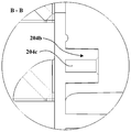
- Figure 7 is a schematic cross-sectional view taken along line B-B of Figure 6;
- Figure 8 is a schematic front view of a fan back cover in accordance with one embodiment of the present invention.
- Figure 9 is a schematic side view of a fan back cover in accordance with one embodiment of the present invention.
- Figure 10 is a schematic side cross-sectional view of a compartment having a blower assembly, in accordance with one embodiment of the present invention.
- Figure 11 is a schematic front view of a portion of a liner in accordance with one embodiment of the present invention.
- Figure 12 is a schematic front view of an evaporator in accordance with one embodiment of the present invention.
- Figure 13 is a schematic cross-sectional view taken along line C-C of Figure 12;
- Figure 14 is a schematic exploded view of a fin in accordance with one embodiment of the present invention.
- the present invention provides a blower assembly for a refrigerator, which can be further included in a blower system and applied to a refrigerator.
- the refrigerator may generally have a casing outer casing as its outer surface and a inner casing located inside the casing outer casing.
- the bladder can define a compartment, and at least a portion of the space within the compartment can be a storage space.
- There may be a plurality of compartments, and may be provided as a refrigerating compartment, a freezing compartment, or a temperature changing compartment as needed.
- airflow passages are generally provided in the refrigerating compartments of some air-cooled or dual-system refrigerators to provide cooling air for the storage space of the refrigerating compartment.
- a blower assembly may be disposed in the airflow passage to form a fast flowing air, or the airflow passage may also be combined with the blower assembly to form a blower system that provides a cooling air to the refrigerating compartment.
- the air supply assembly can be disposed at the most upstream of the air supply system. It can be understood that the most upstream here refers to the source of the air supply path, not the actual installation position of the air supply assembly.
- the air supply system for the refrigerator may include a blower assembly and a heat exchange device.
- the blower assembly may include a duct cover 200 and a centrifugal wind wheel 400.
- the air duct cover 200 may be disposed substantially in parallel with the inner tank 100 of the refrigerator compartment 1 to define a supply air space 20 together with the inter-refrigerator inter-chamber 100, and configured to store the air supply space 20 and the compartment 1
- the object space 10 is isolated.
- the centrifugal rotor 400 may be disposed in the air supply space 20 to take in air from the axial direction and blow it toward the circumferential side.
- the heat exchange device can be an evaporator 500 disposed above the centrifugal rotor 400 and configured to exchange heat with the air flowing therethrough.
- a plurality of air return openings 201 may be defined in the air duct cover 200 to allow air in the storage space 10 to enter the air supply space 20.
- the centrifugal rotor 400 is disposed inwardly of the duct cover 200 and is disposed to suck the rear side to draw air entering the air supply space 20 via the return air opening 201 from the rear side of the centrifugal wind wheel 400.
- the inner side of the air duct cover 200 refers to the side of the air duct cover 200 facing the air supply space 20.
- orientations of “upper”, “lower”, “front” and “rear” mentioned in the specification are defined according to the spatial positional relationship in the normal working state of the refrigerator, for example, the side of the refrigerator facing the user is front, and is placed toward it. One side of the wall of the position is the rear.
- the air duct cover 200 may be disposed in front of the inner tank 100 on the rear side of the refrigerator compartment 1 to form a ventilation space 20 on the rear side of the compartment 1.
- the return air opening 201 formed in the air duct cover 200 allows the air in the storage space 10 to flow into the air supply space 20 from the front to the rear.
- the centrifugal wind wheel 400 configured to inhale on the rear side urges the air entering the air supply space 20 to continue to flow backward and to flow toward the center of the centrifugal wind wheel 400 at a position substantially behind the centrifugal wind wheel 400 and be sucked therein.
- the air supply assembly of the present invention has a return air path from the air return port 201 on the front side of the centrifugal wind wheel 400 to the air intake port 302 on the rear side of the centrifugal wind wheel 400, so that there is no need to leave between the centrifugal wind wheel 400 and the air duct cover 200. There is a gap that increases the volume of the storage space 10 located in front of the duct cover 200.
- the air supply assembly of the present invention bypasses the main body of the centrifugal wind wheel 400 from the front to the rear by the return air path, thereby avoiding the sudden change of the flow direction of the air that has just entered the air supply space 20 via the return air opening 201, so that the flow of the return air It is smoother and extends the return air path, which makes the return air flow gently reduce the return air noise, and avoids the storage due to the large amount of air being sucked to the air supply space side in a short time and concentrated at the centrifugal wind wheel.
- the negative pressure on the space side is too low, which is convenient for the user to open the refrigerator door.
- a fan volute 204 may be disposed inside the air duct cover 200, and the centrifugal wind wheel 400 may be disposed in the fan volute 204.
- the fan volute 204 can be integrally formed with the air duct cover 200, that is, formed inside the air duct cover 200, and the air duct cover 200 can be directly mounted and fixed to the refrigerator compartment 1 through the connecting member. 100 to reduce the components of the air supply assembly and to simplify the assembly process of the air supply assembly.
- a plurality of blind holes 204b are disposed in an inner portion of the air duct cover 200 inside the fan volute 204, and a center of each blind hole 204b protrudes outward to form a mounting post 204c.
- the outer peripheral side of the centrifugal wind wheel 400 is provided with a plurality of mounting rings 400a configured to have an annular shape to be embedded in the blind holes 204b and sleeved on the mounting post 204c in the blind hole 204b, thereby mounting the centrifugal wind wheel 400 The location is limited.
- the air supply assembly further includes a fan back cover 300 disposed between the centrifugal wind wheel 400 and the inner liner 100 and configured to be from the rear side cover of the centrifugal wind wheel 400. It is buckled on the outside to protect the centrifugal rotor 400.
- the fan back cover 300 can be configured to be directly mounted and fixed to the air duct cover 200 between the centrifugal wind wheel 400 and the inner liner 100.
- An air intake port 302 is opened in the fan back cover 300 to allow the centrifugal wind wheel 400 to draw air in the air supply space 20 via the air intake port 302.
- the fan back cover 300 and the fan volute 204 together with the centrifugal wind wheel 400 constitute a centrifugal fan.
- the centrifugal wind wheel 400 can draw air from the axial direction and blow the air upwards out of the centrifugal fan.
- the fan back cover 300 can be directly fixed to the air duct cover 200 and mounted on the inner liner 100 through the air duct cover 200, thereby making the fan rear cover 300, the fan volute 204 and the centrifugal wind wheel 400 common.
- the centrifugal fan is formed together with the air duct cover 200 to form a modular member, which further simplifies the assembly process of the air supply assembly, and is fixed to the air duct cover as compared with the centrifugal fan directly fixed to the inner liner 100.
- the 200 centrifugal fan has less noise during operation.
- the fan volute 204 may have a positioning notch 204a.
- the fan back cover 300 may have a positioning post 301a extending forward from the front surface thereof to insert the positioning notch 204a when the fan back cover 300 is mounted inside the duct cover 200.
- the inner side of the fan back cover 300 may have a double-layered rib 301 shaped with the fan volute 204, and configured to face the fan back cover 300 when the fan back cover 300 is mounted to the air duct cover 200. The ends are inserted into the gap between the double ribs 301.
- the positioning notch 204a may be disposed at a lower side portion of the fan volute 204.
- the positioning post 301a can be disposed between the double-layer ribs 301 and has an arc shape and is the same as the arc of the corresponding positions of the double-layer ribs 301 and the fan volute 204 to embed the positioning notches 204a to complete the fan volute 204.
- the blower assembly is configured to be located on the lower rear side of the compartment 1 above which the airflow passage 22 is disposed.
- An evaporator 500 may be disposed in the air flow passage 22, and a portion of the air flow passage 22 downstream (in the present embodiment, that is, in an upper region of the air flow passage 22) may be provided with an air supply port for supplying air to the storage space 10.
- the centrifugal rotor 400 can be configured to blow up to cause the airflow to accelerate upwardly into the airflow passage 22 and through the evaporator 500 to the air supply. That is, in the vertical direction, the air supply assembly may be located below the lowermost layer of the shelf in the compartment 1 to save the upper space of the storage space 10, increasing the effective volume of the storage space 10.
- the duct cover 200 may include a main body portion 200b and a guide portion 200a, and the fan volute 204 may be disposed inside the main body portion 200b.
- the air duct cover 200 may be composed of upper and lower portions, and the guide portion 200a is located above the main body portion 200b.
- the body portion 200b can be configured to be disposed away from the bladder 100 relative to the airflow passage 22.
- the guide portion 200a may be configured to extend upward from the top end of the main body portion 200b and toward the inner liner 100 to guide the airflow blown by the centrifugal wind wheel 400 to the air flow passage 22. That is, the guide portion 200a and the top of the fan back cover 300 together define the air supply duct of the centrifugal fan.
- the guiding portion 200a is closer to the side of the inner tank 100 with respect to the main body portion 200b of the centrifugal wind wheel 400, thereby gradually reducing the cross-sectional area of the air outlet duct of the centrifugal fan from bottom to top, thereby accelerating the air. flow.
- the cover defining the airflow passage 22 may be configured to extend upwardly from the guide portion 200a of the air duct cover 200. That is, the air flow passage 22 and the air supply space 20 may be separated from the storage space 10 by the same complete cover.
- the corresponding region of the inner liner 100 and the centrifugal rotor 400 is configured to protrude outwardly away from the air duct cover 200 to increase the air supply space 20 on the suction side of the centrifugal wind wheel 400.
- the extent to which the inner liner 100 protrudes outward may be greater than the extent that the main body portion 200b advances "occupies" the storage space 10 to secure the volume of the storage space 10.
- "occupied" herein means that the main body portion 200b is closer to the front side of the casing with respect to the guide portion 200a.
- the rear side of the inner liner 100 is a foamed layer of the refrigerator, the front and rear positions of the inner liner 100 do not significantly affect the foaming effect of the foamed layer.
- the rear side suction centrifugal wind wheel 400 is disposed close to the main body portion 200b, the main body portion 200b does not need to be disposed too far forward, and the air supply assembly of the present invention is reduced in comparison with the front side suction air supply assembly.
- the demand for the wind space 20 is such that the volume of the storage space 10 is larger.
- outwardly protruding refers to the exterior of the air supply space 20, and may be toward the storage space 10 or a foamed layer of the refrigerator facing the rear side of the inner liner 100.
- the present invention also provides an air supply system that can include the aforementioned air supply assembly, heat exchange device (e.g., evaporator 500), and a refrigerator interior that is at least partially used to assist in the delivery of refrigeration air.
- heat exchange device e.g., evaporator 500
- refrigerator interior that is at least partially used to assist in the delivery of refrigeration air.
- a portion of the inner liner 100 of the air supply system located below the evaporator 500 is configured to be bent toward the air duct cover 200 to form a water receiving bottom portion 101 so that the projections of the evaporator 500 in the vertical direction are all dropped.
- the water bottom 101 is connected. That is, the water tank of the refrigerator can be directly formed by bending and extending the inner liner 100 without additional arrangement.
- a portion of the inner liner 100 located below the evaporator 500 and above the water receiving bottom 101 is configured to protrude away from the air duct cover 200 to form the water receiving side portion 102.
- the water receiving bottom portion 101 is disposed closer to the side of the air duct cover 200 than to the side closer to the water receiving side portion 102 so that the water droplets falling thereon flow toward the water receiving side portion 102.
- the intersection of the water receiving side portion 102 and the water receiving bottom portion 101 is configured to have an inclination angle such that the intermediate position thereof is lower than the intermediate position, and the intermediate position is provided with the drainage opening 103 to guide the liquid flowing to the junction.
- the drain port 103 flows out.
- the water receiving side portion 102 can be configured to protrude toward the foam layer to further guide the intersection of the water receiving bottom portion 101 and the water receiving side portion 102 obliquely downward and away from the air outlet duct.
- the air blowing system of the refrigerator of the present invention does not require the use of an additional water tank component, and guides the defrosting water generated in the air blowing system through the inner tank 100 having the water receiving shape. Thereby, the manufacturing cost of the refrigerator is further reduced, and the fitting of the water tank structure and the inner liner 100 is avoided while the defrosting water is completely discharged.
- the air supply assembly may further include a plurality of flow guiding ribs 202 disposed inside the air duct cover 200 and configurable to be located downstream of the air outlet path of the centrifugal wind wheel 400 for centrifuging
- the airflow blown by the wind wheel 400 is divided into multiple strands.
- the duct cover 200 generally has a certain width, and a plurality of guide bars 202 are sequentially disposed laterally along the duct cover 200.
- the plurality of flow guiding ribs 202 may be disposed to be disposed inside the guiding portion 200a at the same interval to divide the airflow blown by the centrifugal wind wheel 400 into multiple strands, and the plurality of airflows are respectively separated by two adjacent The guide bars 202 flow backwards and upwards. Thereby, the wind blown by the centrifugal wind wheel 400 is uniformly flowed to the circumferential side of the evaporator 500 in the air flow passage 22 through the plurality of flow guiding ribs 202 to improve the heat exchange efficiency of the evaporator 500.
- a plurality of water guiding strips 203 may be disposed above the plurality of flow guiding ribs 202 to prevent water droplets from entering the centrifugal fan.
- the water barrier 203 may be disposed at an upper end edge of the guiding portion 200a facing the inner liner 100, and has an oblique downward angle in a direction from the air duct cover 200 to the inner liner 100 to block the portion from the upper portion. The opening of the wind duct. Since the guide portion 200a guides the air blown by the centrifugal fan to blow air backward, the water stop bar 203 located above the guide rib 202 does not adversely affect the amount of airflow and the wind speed of the cooling air sent backward.
- the top of the fan back cover 300 may be provided with a shielding strip 303 configured to extend rearward from the top of the fan back cover 300 to and over the water receiving bottom 101 to shield the inner liner 100 and A return air area 21 between the fan back covers 300. That is, the shielding strip 303 at the top end of the fan back cover 300 completely separates the return air region 21 from the water receiving liner 100, and directs the liquid thereon to flow toward the water receiving liner 100, thereby completely avoiding condensation or water. The frost water enters the centrifugal fan.
- connection of the shielding strip 303 on the side of the fan back cover 300 may be slightly lower than the top end of the fan back cover 300 to prevent the water droplets falling thereon from splashing into the air outlet duct by the top end of the fan back cover 300. Further, the connection of the shielding strip 303 may be disposed on a side of the fan back cover 300 higher than a side overlapping the water receiving bottom 101 to guide the water droplets thereon to flow toward the water receiving bottom 101.
- the body portion 200b is provided with at least one set of return air groups, and each of the return air groups includes a plurality of return air ports 201.
- the return air group may be disposed at an area near the lateral end of the main body portion 200b, and the projections of the plurality of return air openings 201 of the return air group on the air duct cover 200 are located on the air duct cover 200 of the fan volute 204. The outside of the projection.
- the plurality of return air ports 201 can be configured as two return air groups, and each of the return air groups has a plurality of return air ports 201.
- the two return air groups are respectively disposed at positions close to the lateral ends of the main body portion 200b. Thereby, the air in the storage space 10 enters the air supply space 20 from the circumferential side (mainly the lateral sides) of the fan volute 204, so that the change of the flow direction of the return air flow is more gentle, avoiding more excessively large Turn.
- the air return port 201 on the circumferential side of the fan volute 204 of the present invention and the rear side suction air of the centrifugal wind wheel 400 are arranged to reduce the steering angle required for the return air flow, and provide sufficient return flow for the return air flow.
- the direction of the space facilitates the return airflow to be continuously inhaled by the centrifugal wind wheel 400.
- the blower assembly further includes a plurality of shadow caps 201a.
- the plurality of shielding caps 201a may be disposed to be disposed above the plurality of return air openings 201 of the return air group on the storage space 10 side, respectively, to shield the return air outlet 201 from above, and to cause air in the storage space 10 to flow from bottom to top. It is inside the shielding cap 201a and enters the return air opening 201.
- the air return opening 201 on the main body portion 200b may extend in the lateral direction, and a shielding cap 201a is disposed above each of the laterally extending return air outlets 201 to prevent solids such as liquid or particulate debris in the storage space 10 from entering with air. Air supply space 20.
- At least one lateral side end of the duct cover 200 has a side cover 200c that extends toward the inner liner 100.
- At least one return air opening 201 is defined in the side cover 200c.
- the side cover 200c may be formed at one lateral side end of the main body portion 200b.
- the side cover 200c may be formed on both the right and left sides of the main body portion 200b.
- the side cover 200c can abut back against the inner liner 100 to isolate the air supply space 20 and the storage space 10.
- Each of the side cover plates 200c can be provided with a plurality of return air openings 201 to promote air circulation in the compartments 1 and accelerate heat exchange efficiency.
- the return air opening 201 on the side cover 200c may be configured to extend in the vertical direction, and a shielding cap 201a is provided on the front side of each of the air return ports 201 (that is, on the side close to the storage space 10).
- evaporator 500 can have a plurality of linear conduits 501 extending laterally and vertically spaced and a plurality of transition conduits 502 connecting linear conduits 501.
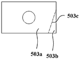
- a plurality of fins 503 are mounted in parallel and spaced apart on each of the straight lines 501, and the plate body 503a of the fins 503 is disposed to be disposed perpendicular to the inner liner 100.
- the oblique portion 503b is located at the bottom of the side of the plate body 503a facing away from the inner liner 100, and is perpendicular to the plate body 503a.
- each of the fins 503 has a bent portion.
- the fins 503 may be configured in a rectangular sheet shape, one corner of which is configured to bend a plane in which most of the plate body 503a of the fin 503 is located to form a chamfered portion 503b, a plate of the obliquely folded portion 503b and the fin 503.
- the bent portion 503c is formed at the bent portion of the body 503a.
- the obliquely folded portion 503b may preferably be an angle located outside the lower end of each of the fins 503 to guide the liquid such as defrosting water on the fins 503 to flow toward the inner side of each of the fins 503 along the obliquely folded side 503c.
- the water droplets dropped from the evaporator 500 as a whole are closer to the inner liner 100, reducing the width requirement of the docking water structure.
- the obliquely folded portion 503b is disposed to be disposed perpendicular to the plate body 503a of the fin 503 such that the end of the obliquely folded portion 503b is as inward as possible while the plate of the fin 503 is made
- the surface of the body 503a and the oblique portion 503b are kept at a certain distance to ensure the contact of the evaporator 500 with the air flowing therethrough, thereby enhancing the heat exchange efficiency.
- the plurality of fins 503 mounted on each of the straight tubes 501 may be disposed such that the respective oblique portions 503b are bent in the same direction, thereby ensuring the defrosting water and the like dripped from the evaporator 500.
- the plurality of linear conduits 501 and the plurality of transition conduits 502 may together form a serpentine conduit, and the plurality of fins 503 located on the plurality of linear conduits 501 at the upper portion of the serpentine conduit may be arranged to be serpentine
- the plurality of fins 503 on the plurality of linear conduits 501 in the lower portion of the conduit are densely arranged.
- the evaporator 500 may have two vertically extending support plates, respectively a left support plate 504a at the left end of the plurality of linear conduits 501, and a right end located at the right end of the plurality of linear conduits 501.
- Support plate 504b Further, the bottom ends of the left support plate 504a and the right support plate 504b each have a fin 503 having a beveled portion 503b, and the two oblique portions 503b of the fins 503 at the ends of the support plate are disposed to face a straight line. The middle portion of the pipe 501 is bent.
- the fin 503 at the end of the support plate may have a plate body 503a and a chamfered portion 503b which are substantially the same as the fin 503 of the linear pipe 501.
- one of the end fins 503 can be configured to have exactly the same structure as the fins 503 of the linear conduit 501, and the other end fins 503 can be configured to mirror the fins 503 of the linear conduit 501. Symmetrical structure.
- the oblique portion 503b of the end fin 503 in the bending direction of the oblique portion 503b of the fin 503 on the straight line 501 is disposed to be curved with the oblique portion 503b of the fin 503 of the straight line 501.
- the folding direction is reversed, that is, it is bent relative to the oblique portion 503b of the straight line 501 fin 503.
- the end portions of the outermost fins 503 of the evaporator 500 are all bent toward the inner side of the evaporator 500, thereby improving the position of the defrosting water flowing and dripping, and reducing the structural size of the docking water tank or the water receiving liner 100. Requirements.
- the evaporator 500 of the present invention can realize the internal movement of the liquid dropping position such as defrosting water only by bending one end angle of the ordinary fin, and the technical solution is simple and easy to implement without other complicated structures.
- bent oblique portion 503b is located between the adjacent two fins 503, that is, on the path of the flow of the heat exchange gas flow, increasing the spoiler 503 to the heat exchange gas flow, and improving the heat exchange efficiency.
- the evaporator 500 having the above-described fins 503 is particularly suitable for mounting in cooperation with the above-described air blowing assembly. Due to the special structure of the air supply assembly described above, a partial area of the inner liner 100 needs to protrude beyond the inside of the air supply space 20 beyond the size of the general evaporator 500.
- the evaporator 500 having the above-mentioned fins 503 can guide the defrosting water to the inside of the evaporator 500 under the premise of ensuring the heat exchange area, and prevent the defrosting water droplets from falling on the water receiving structure (that is, the water receiving bottom of the inner tank 100).
- the water retaining structure of the duct cover 200 such as 200 and the mounting structure connected to the inner liner 100.
- the present invention also provides a refrigerator 1 having a casing 2 including at least one compartment and the above-described air blowing assembly. At least one compartment is the refrigerating compartment 3, and the air supply unit is disposed in the refrigerating compartment 3.
- the refrigerator 1 also has the evaporator 500 described above to simplify the assembly of the blower assembly within the refrigerator.
Abstract
Description
Claims (14)
- 一种用于冰箱的送风组件,包括:风道盖板,与所述冰箱的内胆共同限定出送风空间,且配置成将所述送风空间与位于所述冰箱的间室内的储物空间隔离;离心风轮,设置于所述送风空间内,以自轴向吸入空气并向周侧吹出;其中所述风道盖板上开设有多个回风口,以允许所述储物空间内的空气进入所述送风空间;且所述离心风轮贴靠地设置于所述风道盖板内侧,且配置成后侧吸风,以将经由所述回风口进入所述送风空间的空气自所述离心风轮的后侧吸入。
- 根据权利要求1所述的送风组件,其中,所述内胆的与所述离心风轮的对应区域配置成背离所述风道盖板向外凸出,以增大位于所述离心风轮吸风侧的所述送风空间。
- 根据权利要求1所述的送风组件,其中,所述送风组件配置成位于所述间室的下部后侧,其上方设置有气流通道;所述气流通道内设置有蒸发器,且所述气流通道具有用于向所述储物空间送风的送风口;以及所述离心风轮配置成促使气流加速向上流动进入所述气流通道并通过所述蒸发器流向所述送风口。
- 根据权利要求3所述的送风组件,其中所述风道盖板直接安装固定于所述冰箱的所述内胆,所述风道盖板内侧设有风机蜗壳,所述离心风轮设置于所述风机蜗壳内。
- 根据权利要求4所述的送风组件,其中所述风道盖板内侧形成有所述风机蜗壳,以安装所述离心风轮;且所述风机蜗壳配置成与所述风道盖板一体成型制造而成。
- 根据权利要求4所述的送风组件,还包括:风机后盖,设置于所述离心风轮和所述内胆之间,且配置成自所述离心风轮后侧罩扣于其外部;其中所述风机后盖上开设有吸气口,以允许所述离心风轮经由所述吸气口将所述送风空间内的空气吸入;以及所述风机后盖、所述风机蜗壳和所述离心风轮组成离心风机;且所述风机蜗壳具有定位缺口,所述风机后盖具有自其前表面向前伸出的定位柱,以在所述风机后盖安装于所述风道盖板内侧时插入所述定位缺口。
- 根据权利要求6所述的送风组件,其中,所述风机后盖配置成于所述离心风轮和所述内胆之间直接安装固定于所述风道盖板。
- 根据权利要求4所述的送风组件,其中,所述风道盖板包括主体部和导向部,所述风机蜗壳设置于所述主体部内侧;所述主体部配置成相对于所述气流通道远离所述内胆设置;以及所述导向部配置成自所述主体部的顶端向上且朝向内胆弯折延伸以引导所述离心风 轮吹出的气流流向所述气流通道。
- 根据权利要求8所述的送风组件,其中,所述主体部上设置有至少一组回风组,每个所述回风组包括多个所述回风口;所述回风组配置成位于所述主体部的靠近横向端部的区域;且所述回风组的多个所述回风口在所述风道盖板上的投影均位于所述风机蜗壳在所述风道盖板上的投影的外部。
- 根据权利要求9所述的送风组件,还包括:多个遮蔽帽,配置成分别在所述储物空间侧设置于所述回风组的多个所述回风口的上方,以自上方遮蔽所述回风口,且使所述储物空间内的空气自下向上流动至遮蔽帽内侧并进入所述回风口。
- 根据权利要求1所述的送风组件,其中,所述风道盖板的至少一个横向侧端设置有朝向所述内胆弯折延伸的侧部盖板;且所述侧部盖板上开设有至少一个所述回风口。
- 一种用于冰箱的送风系统,包括根据权利要求1所述的送风组件,以及蒸发器,设置于所述离心风轮上方,配置成与流经其的空气换热;其中所述离心风轮配置成自其轴向吸入空气并向上吹出;以及位于所述蒸发器下方的部分所述内胆配置成朝向所述风道盖板弯折延伸以形成接水底部,且所述部分内胆使所述蒸发器在竖直方向上的投影均落入所述接水底部。
- 根据权利要求12所述的送风系统,其中,位于所述蒸发器下方且位于所述接水底部上方的部分内胆配置成背离所述风道盖板凸出以形成接水侧部;所述接水底部配置成靠近所述风道盖板的一侧高于靠近所述接水侧部的一侧,以使落在其上的水滴朝向所述接水侧部流动;以及所述接水侧部与所述接水底部的交汇处配置成具有使其中间位置低于远离所述中间位置的倾斜角度,且所述中间位置开设有排水口,以引导流动至所述交汇处的液体自所述排水口流出。
- 一种冰箱,具有包括至少一个所述间室的箱体和根据权利要求1至11任一所述的送风组件,其中,至少一个所述间室为冷藏间室,且所述送风组件设置于所述冷藏间室内。
Priority Applications (4)
| Application Number | Priority Date | Filing Date | Title |
|---|---|---|---|
| US16/961,077 US11713915B2 (en) | 2018-01-09 | 2019-01-08 | Air supply assembly, air supply system and refrigerator |
| AU2019206946A AU2019206946B2 (en) | 2018-01-09 | 2019-01-08 | Air supply assembly, air supply system and refrigerator |
| MX2020007104A MX2020007104A (es) | 2018-01-09 | 2019-01-08 | Ensamble de suministro de aire, sistema de suministro de aire y refrigerador. |
| EP19739003.2A EP3722711B1 (en) | 2018-01-09 | 2019-01-08 | Refrigerator |
Applications Claiming Priority (8)
| Application Number | Priority Date | Filing Date | Title |
|---|---|---|---|
| CN201810020183.1A CN110017640B (zh) | 2018-01-09 | 2018-01-09 | 送风组件及具有其的冰箱 |
| CN201810019798.2 | 2018-01-09 | ||
| CN201810020183.1 | 2018-01-09 | ||
| CN201810020188.4 | 2018-01-09 | ||
| CN201810020188.4A CN110017648B (zh) | 2018-01-09 | 2018-01-09 | 送风组件及具有其的冰箱 |
| CN201810020184.6A CN110017641B (zh) | 2018-01-09 | 2018-01-09 | 送风系统及具有其的冰箱 |
| CN201810020184.6 | 2018-01-09 | ||
| CN201810019798.2A CN110017646B (zh) | 2018-01-09 | 2018-01-09 | 送风组件及具有其的冰箱 |
Publications (1)
| Publication Number | Publication Date |
|---|---|
| WO2019137375A1 true WO2019137375A1 (zh) | 2019-07-18 |
Family
ID=67218900
Family Applications (1)
| Application Number | Title | Priority Date | Filing Date |
|---|---|---|---|
| PCT/CN2019/070868 WO2019137375A1 (zh) | 2018-01-09 | 2019-01-08 | 送风组件、送风系统及冰箱 |
Country Status (5)
| Country | Link |
|---|---|
| US (1) | US11713915B2 (zh) |
| EP (1) | EP3722711B1 (zh) |
| AU (1) | AU2019206946B2 (zh) |
| MX (1) | MX2020007104A (zh) |
| WO (1) | WO2019137375A1 (zh) |
Families Citing this family (1)
| Publication number | Priority date | Publication date | Assignee | Title |
|---|---|---|---|---|
| CN112797692B (zh) * | 2019-11-14 | 2024-01-12 | 博西华电器(江苏)有限公司 | 带速冷抽屉的冰箱 |
Citations (7)
| Publication number | Priority date | Publication date | Assignee | Title |
|---|---|---|---|---|
| JPH07260315A (ja) * | 1994-03-28 | 1995-10-13 | Hitachi Ltd | 冷凍冷蔵庫 |
| CN202835994U (zh) * | 2012-08-28 | 2013-03-27 | 青岛海尔模具有限公司 | 冰箱的风循环系统的结构 |
| CN103673465A (zh) * | 2012-09-12 | 2014-03-26 | 青岛海尔模具有限公司 | 用于大容积风冷冰箱的送风系统及风冷冰箱 |
| CN104101159A (zh) * | 2014-08-06 | 2014-10-15 | 合肥华凌股份有限公司 | 冰箱的风道组件和冰箱 |
| CN104374138A (zh) * | 2014-11-28 | 2015-02-25 | 合肥华凌股份有限公司 | 风冷冰箱 |
| CN204438646U (zh) * | 2014-12-30 | 2015-07-01 | Tcl智能科技(合肥)有限公司 | 风道组件及具有该风道组件的冰箱 |
| CN104792085A (zh) * | 2015-04-01 | 2015-07-22 | 合肥华凌股份有限公司 | 冰箱风道结构及风冷冰箱 |
Family Cites Families (17)
| Publication number | Priority date | Publication date | Assignee | Title |
|---|---|---|---|---|
| US3004400A (en) | 1960-07-08 | 1961-10-17 | Gen Motors Corp | Two compartment frost-free refrigerator |
| US3365118A (en) * | 1966-05-20 | 1968-01-23 | Gen Motors Corp | Circulating system |
| US3375677A (en) * | 1967-01-03 | 1968-04-02 | Gen Motors Corp | Method and apparatus for maintaining high humidity in a frost-free domestic refrigerator |
| US3893307A (en) * | 1974-05-03 | 1975-07-08 | Gen Motors Corp | Refrigerator freezer with frost eliminator |
| KR100423958B1 (ko) * | 1999-01-19 | 2004-03-22 | 삼성전자주식회사 | 냉장고의 냉기 순환장치 |
| EP2082176B1 (en) * | 2006-11-06 | 2018-08-15 | LG Electronics Inc. | Fan motor assembly for blowing cooling air and refrigerator having the same |
| KR20090032733A (ko) * | 2007-09-28 | 2009-04-01 | 엘지전자 주식회사 | 냉장고의 방열 장치 |
| KR20090046297A (ko) | 2007-11-05 | 2009-05-11 | 엘지전자 주식회사 | 음식물 보관기기 |
| WO2013029686A1 (en) * | 2011-09-02 | 2013-03-07 | Carrier Corporation | Refrigerated sales furniture |
| KR102326481B1 (ko) * | 2014-09-02 | 2021-11-16 | 삼성전자주식회사 | 냉장고 |
| US10101077B2 (en) * | 2014-09-25 | 2018-10-16 | Electrolux Home Products, Inc. | Fan mounting assembly, evaporator coil cover and air tower of refrigerator |
| CN105115218B (zh) * | 2015-09-09 | 2018-02-13 | 合肥华凌股份有限公司 | 一种冰箱回风系统及方法 |
| CN105402978B (zh) | 2015-11-30 | 2017-08-11 | 合肥美菱股份有限公司 | 冰箱的风道装置及全变温冰箱 |
| CN106123443B (zh) | 2016-06-28 | 2018-10-12 | 青岛海尔股份有限公司 | 冰箱 |
| CN106500438A (zh) * | 2016-10-24 | 2017-03-15 | 合肥华凌股份有限公司 | 一种风道组件及制冷装置 |
| CN106839572A (zh) * | 2017-01-20 | 2017-06-13 | 美的集团股份有限公司 | 风道结构和冰箱 |
| CN107192198B (zh) | 2017-06-29 | 2020-01-03 | 青岛海尔股份有限公司 | 冰箱 |
-
2019
- 2019-01-08 US US16/961,077 patent/US11713915B2/en active Active
- 2019-01-08 MX MX2020007104A patent/MX2020007104A/es unknown
- 2019-01-08 AU AU2019206946A patent/AU2019206946B2/en active Active
- 2019-01-08 EP EP19739003.2A patent/EP3722711B1/en active Active
- 2019-01-08 WO PCT/CN2019/070868 patent/WO2019137375A1/zh unknown
Patent Citations (7)
| Publication number | Priority date | Publication date | Assignee | Title |
|---|---|---|---|---|
| JPH07260315A (ja) * | 1994-03-28 | 1995-10-13 | Hitachi Ltd | 冷凍冷蔵庫 |
| CN202835994U (zh) * | 2012-08-28 | 2013-03-27 | 青岛海尔模具有限公司 | 冰箱的风循环系统的结构 |
| CN103673465A (zh) * | 2012-09-12 | 2014-03-26 | 青岛海尔模具有限公司 | 用于大容积风冷冰箱的送风系统及风冷冰箱 |
| CN104101159A (zh) * | 2014-08-06 | 2014-10-15 | 合肥华凌股份有限公司 | 冰箱的风道组件和冰箱 |
| CN104374138A (zh) * | 2014-11-28 | 2015-02-25 | 合肥华凌股份有限公司 | 风冷冰箱 |
| CN204438646U (zh) * | 2014-12-30 | 2015-07-01 | Tcl智能科技(合肥)有限公司 | 风道组件及具有该风道组件的冰箱 |
| CN104792085A (zh) * | 2015-04-01 | 2015-07-22 | 合肥华凌股份有限公司 | 冰箱风道结构及风冷冰箱 |
Non-Patent Citations (1)
| Title |
|---|
| See also references of EP3722711A4 * |
Also Published As
| Publication number | Publication date |
|---|---|
| AU2019206946A1 (en) | 2020-07-09 |
| MX2020007104A (es) | 2020-09-09 |
| EP3722711B1 (en) | 2022-06-22 |
| AU2019206946B2 (en) | 2021-09-09 |
| EP3722711A1 (en) | 2020-10-14 |
| EP3722711A4 (en) | 2021-01-20 |
| US11713915B2 (en) | 2023-08-01 |
| US20210063074A1 (en) | 2021-03-04 |
Similar Documents
| Publication | Publication Date | Title |
|---|---|---|
| JP4827899B2 (ja) | 天井埋込形空気調和機 | |
| CN101957029B (zh) | 一体式空调器 | |
| WO2020098082A1 (zh) | 冰箱 | |
| WO2022037719A1 (zh) | 将冷凝器布置于压机舱内的冰箱 | |
| WO2019137375A1 (zh) | 送风组件、送风系统及冰箱 | |
| CN111520952A (zh) | 半导体冷箱的散热系统 | |
| CN110017639B (zh) | 冰箱 | |
| CN110017641B (zh) | 送风系统及具有其的冰箱 | |
| WO2022037382A1 (zh) | 嵌入式冰箱 | |
| CN213955469U (zh) | 整体式空调器 | |
| CN110017640B (zh) | 送风组件及具有其的冰箱 | |
| CN110017645B (zh) | 送风组件及具有其的冰箱 | |
| CN110017648B (zh) | 送风组件及具有其的冰箱 | |
| CN110017646B (zh) | 送风组件及具有其的冰箱 | |
| CN110017647B (zh) | 送风系统及具有其的冰箱 | |
| US11933533B2 (en) | Blower and refrigerator | |
| CN218781368U (zh) | 空调器 | |
| CN210463253U (zh) | 空调室内机 | |
| CN100412453C (zh) | 整体式空调器的空气导向装置 | |
| WO2022037718A1 (zh) | 将冷凝器布置于压机舱内的冰箱 | |
| CN209706232U (zh) | 便携式空调 | |
| US20210239383A1 (en) | Refrigerator | |
| CN115419946A (zh) | 壁挂式空调器 | |
| CN115682159A (zh) | 空调器 | |
| JP2003222459A (ja) | 冷蔵庫 |
Legal Events
| Date | Code | Title | Description |
|---|---|---|---|
| 121 | Ep: the epo has been informed by wipo that ep was designated in this application |
Ref document number: 19739003 Country of ref document: EP Kind code of ref document: A1 |
|
| ENP | Entry into the national phase |
Ref document number: 2019206946 Country of ref document: AU Date of ref document: 20190108 Kind code of ref document: A |
|
| ENP | Entry into the national phase |
Ref document number: 2019739003 Country of ref document: EP Effective date: 20200707 |
|
| NENP | Non-entry into the national phase |
Ref country code: DE |