WO2019132179A1 - 고강도 고인성 열연강판 및 그 제조방법 - Google Patents
고강도 고인성 열연강판 및 그 제조방법 Download PDFInfo
- Publication number
- WO2019132179A1 WO2019132179A1 PCT/KR2018/010935 KR2018010935W WO2019132179A1 WO 2019132179 A1 WO2019132179 A1 WO 2019132179A1 KR 2018010935 W KR2018010935 W KR 2018010935W WO 2019132179 A1 WO2019132179 A1 WO 2019132179A1
- Authority
- WO
- WIPO (PCT)
- Prior art keywords
- steel sheet
- less
- hot
- rolled steel
- temperature
- Prior art date
Links
Classifications
-
- C—CHEMISTRY; METALLURGY
- C22—METALLURGY; FERROUS OR NON-FERROUS ALLOYS; TREATMENT OF ALLOYS OR NON-FERROUS METALS
- C22C—ALLOYS
- C22C38/00—Ferrous alloys, e.g. steel alloys
- C22C38/18—Ferrous alloys, e.g. steel alloys containing chromium
- C22C38/40—Ferrous alloys, e.g. steel alloys containing chromium with nickel
- C22C38/50—Ferrous alloys, e.g. steel alloys containing chromium with nickel with titanium or zirconium
-
- C—CHEMISTRY; METALLURGY
- C21—METALLURGY OF IRON
- C21D—MODIFYING THE PHYSICAL STRUCTURE OF FERROUS METALS; GENERAL DEVICES FOR HEAT TREATMENT OF FERROUS OR NON-FERROUS METALS OR ALLOYS; MAKING METAL MALLEABLE, e.g. BY DECARBURISATION OR TEMPERING
- C21D8/00—Modifying the physical properties by deformation combined with, or followed by, heat treatment
- C21D8/02—Modifying the physical properties by deformation combined with, or followed by, heat treatment during manufacturing of plates or strips
- C21D8/0221—Modifying the physical properties by deformation combined with, or followed by, heat treatment during manufacturing of plates or strips characterised by the working steps
- C21D8/0226—Hot rolling
-
- C—CHEMISTRY; METALLURGY
- C21—METALLURGY OF IRON
- C21D—MODIFYING THE PHYSICAL STRUCTURE OF FERROUS METALS; GENERAL DEVICES FOR HEAT TREATMENT OF FERROUS OR NON-FERROUS METALS OR ALLOYS; MAKING METAL MALLEABLE, e.g. BY DECARBURISATION OR TEMPERING
- C21D6/00—Heat treatment of ferrous alloys
-
- C—CHEMISTRY; METALLURGY
- C21—METALLURGY OF IRON
- C21D—MODIFYING THE PHYSICAL STRUCTURE OF FERROUS METALS; GENERAL DEVICES FOR HEAT TREATMENT OF FERROUS OR NON-FERROUS METALS OR ALLOYS; MAKING METAL MALLEABLE, e.g. BY DECARBURISATION OR TEMPERING
- C21D6/00—Heat treatment of ferrous alloys
- C21D6/004—Heat treatment of ferrous alloys containing Cr and Ni
-
- C—CHEMISTRY; METALLURGY
- C21—METALLURGY OF IRON
- C21D—MODIFYING THE PHYSICAL STRUCTURE OF FERROUS METALS; GENERAL DEVICES FOR HEAT TREATMENT OF FERROUS OR NON-FERROUS METALS OR ALLOYS; MAKING METAL MALLEABLE, e.g. BY DECARBURISATION OR TEMPERING
- C21D8/00—Modifying the physical properties by deformation combined with, or followed by, heat treatment
- C21D8/02—Modifying the physical properties by deformation combined with, or followed by, heat treatment during manufacturing of plates or strips
- C21D8/0205—Modifying the physical properties by deformation combined with, or followed by, heat treatment during manufacturing of plates or strips of ferrous alloys
-
- C—CHEMISTRY; METALLURGY
- C21—METALLURGY OF IRON
- C21D—MODIFYING THE PHYSICAL STRUCTURE OF FERROUS METALS; GENERAL DEVICES FOR HEAT TREATMENT OF FERROUS OR NON-FERROUS METALS OR ALLOYS; MAKING METAL MALLEABLE, e.g. BY DECARBURISATION OR TEMPERING
- C21D8/00—Modifying the physical properties by deformation combined with, or followed by, heat treatment
- C21D8/02—Modifying the physical properties by deformation combined with, or followed by, heat treatment during manufacturing of plates or strips
- C21D8/0247—Modifying the physical properties by deformation combined with, or followed by, heat treatment during manufacturing of plates or strips characterised by the heat treatment
- C21D8/0263—Modifying the physical properties by deformation combined with, or followed by, heat treatment during manufacturing of plates or strips characterised by the heat treatment following hot rolling
-
- C—CHEMISTRY; METALLURGY
- C21—METALLURGY OF IRON
- C21D—MODIFYING THE PHYSICAL STRUCTURE OF FERROUS METALS; GENERAL DEVICES FOR HEAT TREATMENT OF FERROUS OR NON-FERROUS METALS OR ALLOYS; MAKING METAL MALLEABLE, e.g. BY DECARBURISATION OR TEMPERING
- C21D8/00—Modifying the physical properties by deformation combined with, or followed by, heat treatment
- C21D8/02—Modifying the physical properties by deformation combined with, or followed by, heat treatment during manufacturing of plates or strips
- C21D8/0294—Modifying the physical properties by deformation combined with, or followed by, heat treatment during manufacturing of plates or strips involving a localised treatment
-
- C—CHEMISTRY; METALLURGY
- C21—METALLURGY OF IRON
- C21D—MODIFYING THE PHYSICAL STRUCTURE OF FERROUS METALS; GENERAL DEVICES FOR HEAT TREATMENT OF FERROUS OR NON-FERROUS METALS OR ALLOYS; MAKING METAL MALLEABLE, e.g. BY DECARBURISATION OR TEMPERING
- C21D9/00—Heat treatment, e.g. annealing, hardening, quenching or tempering, adapted for particular articles; Furnaces therefor
- C21D9/46—Heat treatment, e.g. annealing, hardening, quenching or tempering, adapted for particular articles; Furnaces therefor for sheet metals
-
- C—CHEMISTRY; METALLURGY
- C22—METALLURGY; FERROUS OR NON-FERROUS ALLOYS; TREATMENT OF ALLOYS OR NON-FERROUS METALS
- C22C—ALLOYS
- C22C38/00—Ferrous alloys, e.g. steel alloys
-
- C—CHEMISTRY; METALLURGY
- C22—METALLURGY; FERROUS OR NON-FERROUS ALLOYS; TREATMENT OF ALLOYS OR NON-FERROUS METALS
- C22C—ALLOYS
- C22C38/00—Ferrous alloys, e.g. steel alloys
- C22C38/001—Ferrous alloys, e.g. steel alloys containing N
-
- C—CHEMISTRY; METALLURGY
- C22—METALLURGY; FERROUS OR NON-FERROUS ALLOYS; TREATMENT OF ALLOYS OR NON-FERROUS METALS
- C22C—ALLOYS
- C22C38/00—Ferrous alloys, e.g. steel alloys
- C22C38/002—Ferrous alloys, e.g. steel alloys containing In, Mg, or other elements not provided for in one single group C22C38/001 - C22C38/60
-
- C—CHEMISTRY; METALLURGY
- C22—METALLURGY; FERROUS OR NON-FERROUS ALLOYS; TREATMENT OF ALLOYS OR NON-FERROUS METALS
- C22C—ALLOYS
- C22C38/00—Ferrous alloys, e.g. steel alloys
- C22C38/02—Ferrous alloys, e.g. steel alloys containing silicon
-
- C—CHEMISTRY; METALLURGY
- C22—METALLURGY; FERROUS OR NON-FERROUS ALLOYS; TREATMENT OF ALLOYS OR NON-FERROUS METALS
- C22C—ALLOYS
- C22C38/00—Ferrous alloys, e.g. steel alloys
- C22C38/04—Ferrous alloys, e.g. steel alloys containing manganese
-
- C—CHEMISTRY; METALLURGY
- C22—METALLURGY; FERROUS OR NON-FERROUS ALLOYS; TREATMENT OF ALLOYS OR NON-FERROUS METALS
- C22C—ALLOYS
- C22C38/00—Ferrous alloys, e.g. steel alloys
- C22C38/06—Ferrous alloys, e.g. steel alloys containing aluminium
-
- C—CHEMISTRY; METALLURGY
- C22—METALLURGY; FERROUS OR NON-FERROUS ALLOYS; TREATMENT OF ALLOYS OR NON-FERROUS METALS
- C22C—ALLOYS
- C22C38/00—Ferrous alloys, e.g. steel alloys
- C22C38/18—Ferrous alloys, e.g. steel alloys containing chromium
- C22C38/40—Ferrous alloys, e.g. steel alloys containing chromium with nickel
- C22C38/42—Ferrous alloys, e.g. steel alloys containing chromium with nickel with copper
-
- C—CHEMISTRY; METALLURGY
- C22—METALLURGY; FERROUS OR NON-FERROUS ALLOYS; TREATMENT OF ALLOYS OR NON-FERROUS METALS
- C22C—ALLOYS
- C22C38/00—Ferrous alloys, e.g. steel alloys
- C22C38/18—Ferrous alloys, e.g. steel alloys containing chromium
- C22C38/40—Ferrous alloys, e.g. steel alloys containing chromium with nickel
- C22C38/44—Ferrous alloys, e.g. steel alloys containing chromium with nickel with molybdenum or tungsten
-
- C—CHEMISTRY; METALLURGY
- C22—METALLURGY; FERROUS OR NON-FERROUS ALLOYS; TREATMENT OF ALLOYS OR NON-FERROUS METALS
- C22C—ALLOYS
- C22C38/00—Ferrous alloys, e.g. steel alloys
- C22C38/18—Ferrous alloys, e.g. steel alloys containing chromium
- C22C38/40—Ferrous alloys, e.g. steel alloys containing chromium with nickel
- C22C38/48—Ferrous alloys, e.g. steel alloys containing chromium with nickel with niobium or tantalum
-
- C—CHEMISTRY; METALLURGY
- C21—METALLURGY OF IRON
- C21D—MODIFYING THE PHYSICAL STRUCTURE OF FERROUS METALS; GENERAL DEVICES FOR HEAT TREATMENT OF FERROUS OR NON-FERROUS METALS OR ALLOYS; MAKING METAL MALLEABLE, e.g. BY DECARBURISATION OR TEMPERING
- C21D2211/00—Microstructure comprising significant phases
- C21D2211/005—Ferrite
-
- C—CHEMISTRY; METALLURGY
- C21—METALLURGY OF IRON
- C21D—MODIFYING THE PHYSICAL STRUCTURE OF FERROUS METALS; GENERAL DEVICES FOR HEAT TREATMENT OF FERROUS OR NON-FERROUS METALS OR ALLOYS; MAKING METAL MALLEABLE, e.g. BY DECARBURISATION OR TEMPERING
- C21D2211/00—Microstructure comprising significant phases
- C21D2211/009—Pearlite
-
- C—CHEMISTRY; METALLURGY
- C21—METALLURGY OF IRON
- C21D—MODIFYING THE PHYSICAL STRUCTURE OF FERROUS METALS; GENERAL DEVICES FOR HEAT TREATMENT OF FERROUS OR NON-FERROUS METALS OR ALLOYS; MAKING METAL MALLEABLE, e.g. BY DECARBURISATION OR TEMPERING
- C21D2221/00—Treating localised areas of an article
- C21D2221/02—Edge parts
-
- Y—GENERAL TAGGING OF NEW TECHNOLOGICAL DEVELOPMENTS; GENERAL TAGGING OF CROSS-SECTIONAL TECHNOLOGIES SPANNING OVER SEVERAL SECTIONS OF THE IPC; TECHNICAL SUBJECTS COVERED BY FORMER USPC CROSS-REFERENCE ART COLLECTIONS [XRACs] AND DIGESTS
- Y02—TECHNOLOGIES OR APPLICATIONS FOR MITIGATION OR ADAPTATION AGAINST CLIMATE CHANGE
- Y02P—CLIMATE CHANGE MITIGATION TECHNOLOGIES IN THE PRODUCTION OR PROCESSING OF GOODS
- Y02P10/00—Technologies related to metal processing
- Y02P10/20—Recycling
Definitions
- the present invention relates to a high-strength high-strength hot-rolled steel sheet used for construction, a line pipe and a well pipe, and a method of manufacturing the same. More particularly, the present invention relates to a high-strength and high-
- the steel pipe for oil well is applied up to 5km down from the upper part of oil field.
- the steel pipe used for oil well pipe has high strength, high internal and external pressure strength, Delayed fracture and the like are required.
- the steel pipe for oil well used for repairing and maintaining the oil well is subjected to repetitive bending during use, so that the material of the steel pipe is required to be uniform. If the strength of the steel pipe is not uniform in the circumferential direction or the longitudinal direction, there arises a problem that the buckling or breakage occurs preferentially in the region where the strength is weak at the time of repeated bending.
- the thickness of the steel used for making the steel pipe used for the repair and maintenance of the oil well is about 2 to 5 mm and the thickness deviation occurs at both edge portions due to excessive bending of the rolling roll during hot rolling, The edges are excessively cooled due to abrasion at the center portion during cooling, and thus the material in the width direction is liable to be generated. Further, when mining is performed in the polar region, an excellent low temperature toughness at -40 ° C or less is required.
- Patent Document 1 Korean Patent Laid-Open Publication No. 2016-0077385
- a preferred aspect of the present invention is to provide a high-strength hot-rolled steel sheet excellent in low-temperature toughness with a small deviation in the steel sheet width direction strength.
- Another aspect of the present invention is to provide a method for manufacturing a high-strength hot-rolled steel sheet excellent in low-temperature toughness while minimizing variation in the steel sheet widthwise direction by optimizing the component and hot rolling process.
- a ferritic stainless steel comprising: 0.07 to 0.13% of C, 0.20 to 0.50% of Si, 0.5 to 0.9% of Mn, 0.03% or less of P, 0.001 to 0.03% of Cr, 0.3 to 0.6% of Cr, 0.005 to 0.03% of Ti, 0.1 to 0.35% of Cu, 0.05 to 0.3% of Ni, 0.01 to 0.15% of Mo, , Al: 0.01 to 0.05%, and the balance of Fe and other unavoidable impurities;
- alloying elements have the following relationship
- the microstructure includes 85% or more of polygonal ferrite and 15% or less of pearlite in an area fraction, and the grain size of the polygonal ferrite is 10 ⁇ or less; And a high-strength and high-strength hot-rolled steel sheet having a yield strength deviation in the width direction of 35 MPa or less.
- the hot-rolled steel sheet is less than 20nm, the number of precipitates per unit mm2 be 7 ⁇ 10 8 or more
- the hot-rolled steel sheet had a impact toughness value of 95 J or more as measured by Charpy impact test at -60 ⁇ , a separation of 0.01 mm or less at the fracture surface of the impact specimen, a room temperature yield strength of 520 MPa or more, May be at least 640 MPa.
- a steel sheet comprising, by weight%, 0.07 to 0.13% of C, 0.20 to 0.50% of Si, 0.5 to 0.9% of Mn, 0.03% or less of P, 0.001 to 0.03% of Cr, 0.3 to 0.6% of Cr, 0.005 to 0.03% of Ti, 0.1 to 0.35% of Cu, 0.05 to 0.3% of Ni, 0.01 to 0.15% of Mo, 0.007% %, Al: 0.01 to 0.05%, the balance being Fe and other unavoidable impurities,
- alloying elements have the following relationship
- the steel slabs heated and extracted as described above are subjected to primary hot rolling under the conditions of a rolling finish temperature of 900 to 1000 ° C and a reduction rate per recirculating reverse path of 10% or more, and then subjected to a rolling finish temperature of 750 to 870 ° C and a rolling finish temperature of 85% Obtaining a hot-rolled steel sheet by secondary hot rolling under conditions of a non-recrystallized inverse cumulative rolling reduction; And
- the hot rolling may be carried out such that the thickness deviation of the steel plate edge portion and the edge at a point of 100 mm is 90 mm or less.
- the application of heat energy to the edge portions of the steel sheet can be performed so that the temperature variation in the width direction of the steel sheet during water cooling is 150 ° C or less.
- the application of thermal energy to both edge portions of the steel sheet is performed by using an edge heater and an edge mask .
- the steel sheet has a yield strength deviation in the width direction of 35 MPa or less, an impact toughness value measured by a Charpy impact test at -60 ⁇ of 95 J or more, a separation at a fracture surface of the impact specimen of 0.01 mm or less,
- the strength may be 520 MPa or more, and the tensile strength at room temperature may be 640 MPa or more.
- An object of the present invention is to provide a high strength, high toughness hot-rolled steel sheet which is optimized in component and component range, component relation and manufacturing conditions to provide a low temperature toughness with a small steel sheet width direction deviation and a method of manufacturing the same.
- a high strength and high toughness hot-rolled steel sheet comprises 0.07 to 0.13% of C, 0.20 to 0.50% of Si, 0.5 to 0.9% of Mn, 0.03% or less of P and 0.02% or less of S 0.001 to 0.03% of Nb, 0.3 to 0.6% of Cr, 0.005 to 0.03% of Ti, 0.1 to 0.35% of Cu, 0.05 to 0.3% of Ni, 0.01 to 0.15% : 0.001 to 0.006%, Al: 0.01 to 0.05%, and the balance of Fe and other unavoidable impurities;
- alloying elements have the following relationship
- C is an element which increases the hardenability of the steel.
- the content is less than 0.07%, the hardenability is insufficient and the intended strength in the present invention can not be secured.
- the content exceeds 0.13%, the yield strength becomes too high, which makes processing difficult or deteriorates the low-temperature toughness. Therefore, in the present invention, it is preferable to control the content of C to 0.07 to 0.13%.
- the Si increases the C activity in the ferrite phase and promotes ferrite stabilization, and contributes to securing strength by solid solution strengthening. Also, the Si is to form a low-melting oxide such as ERW welding Mn 2 SiO 4 and the oxide easily discharged at the time of welding. If the content is less than 0.2%, a problem of cost in the steelmaking occurs. On the other hand, when the content exceeds 0.5%, the amount of SiO 2 oxide having a high melting point in addition to Mn 2 SiO 4 increases, . Therefore, the Si content is preferably limited to 0.20 to 0.50%.
- the Mn has a large effect on the austenite / ferrite transformation start temperature and lowers the transformation starting temperature, and affects the toughness of the pipe base material portion and the welded portion, and contributes to the strength increase as a solid solution strengthening element. If the content is less than 0.5%, it is difficult to expect the above effect, whereas if the content is more than 0.9%, it is highly likely to occur. Therefore, the content of Mn is preferably limited to 0.5 to 0.9%.
- P is an element that is inevitably contained in the steel, and when phosphorus is added, it is segregated at the center of the steel sheet and can be used as a crack starting point or an advancement path.
- the upper limit of the phosphorus content is preferably limited to 0.03%.
- S is an impurity element present in the steel, which is combined with Mn or the like to form a nonmetallic inclusive material, thereby greatly impairing the toughness of the steel. Therefore, it is desirable to reduce the S as much as possible.
- Nb is a very useful element for suppressing recrystallization during rolling and fine grain growth and it also improves the strength of steel. If it exceeds 0.03%, excess Nb carbonitride It is harmful to the toughness of the steel material, so it is preferable to control it to 0.005-0.03%.
- the Cr is an element which improves the hardenability and the corrosion resistance. If the content of Cr is less than 0.3%, the effect of improving the corrosion resistance by the addition is insufficient, while if it exceeds 0.6%, the weldability may be drastically deteriorated. Therefore, it is preferable to control the Cr content to 0.3 to 0.6%.
- the Ti is an element that bonds with nitrogen (N) in the steel to form TiN precipitates.
- N nitrogen
- excessive coarsening of some austenite grains may occur during high-temperature hot rolling, so that the austenite grain growth can be suppressed by properly depositing TiN.
- the content exceeds 0.03%, the effect is not only saturated but also the effect of the coarse TiN can be reduced by half, which is not preferable. Therefore, in the present invention, it is preferable to limit the Ti content to 0.005 to 0.03%.
- the Cu is effective for improving hardenability and corrosion resistance of the base material and the welded portion.
- the content is less than 0.1%, it is disadvantageous for ensuring corrosion resistance.
- the content exceeds 0.35%, the manufacturing cost is increased and economically disadvantageous, and the range is preferably limited to 0.1 to 0.35%.
- the Ni is effective for improving hardenability and corrosion resistance.
- Cu when Cu is added together with Cu, it reacts with Cu to inhibit the formation of a Cu phase having a low melting point, thereby suppressing the problem of cracking during hot working.
- Such Ni is an effective element for improving the toughness of the base material.
- it is necessary to add Ni at 0.05% or more, but since it is an expensive element, addition of more than 0.3% is disadvantageous in terms of economy.
- the content of Ni is preferably limited to 0.05 to 0.3%.
- Mo is very effective for raising the strength of the material and can suppress the formation of pearlite structure and ensure good impact toughness.
- Mo is preferable to add Mo of 0.01% or more, but it is preferable to limit the Mo content to 0.15% or less in order to inhibit welding low-temperature cracking and to prevent low-temperature transformation phase from being generated in the base material.
- N is fixed as a nitride such as Ti, Al or the like because it causes aging deterioration under the employment state.
- the content exceeds 0.007%, the addition amount of Ti, Al or the like is inevitably increased. Therefore, the content of N is preferably limited to 0.007% or less.
- Ca is added to control the morphology of the emulsion.
- CaS of the CaO cluster is generated with respect to the amount of S in the low-carbon steel.
- the content is less than 0.001%, MnS occurs and the toughness may be lowered.
- the content of Ca is preferably limited to 0.001 to 0.006%.
- Al is added for deoxidation at the time of steel making. If the content is less than 0.01%, such action is insufficient. On the other hand, if the content is more than 0.05%, the formation of a composite oxide containing alumina or alumina oxide promotes the formation of a welded portion during electric resistance welding and may deteriorate the toughness of the welded portion. Therefore, the content of Al is preferably limited to 0.01 to 0.05%.
- the above relational expression 1 is for preventing P segregation.
- the value of the relational expression 1 is less than 1.6, the effect of the P-type segregation due to formation of the Fe-Mo-P compound is insufficient.
- the value of the relational expression 1 exceeds 6, .
- Relational expression 2 is for suppressing the formation of cracks and the formation of nonmetallic inclusions which act as propagation paths when the steel tube is expanded. If it is less than 1.6, MnS can be easily formed, and it is stretched during rolling to act as a propagation path of cracks. When the ratio is more than 3, Ca nonmetallic inclusions are increased and separation occurs on the fracture surface of the impact specimen during steel and steel pipe impact tests. . In some cases, the value of the relational expression (2) may be 1.7 or more.
- Relation 3 is intended to inhibit the formation of brittle bainite and martensite and / or austenite (MA) phases.
- the increase of C and Mn lowers the coagulation temperature of the slab to promote the segregation of the center of the slab, and narrows the interval of the delta ferrite, making it difficult to homogenize the slab during the performance.
- Mn is a typical element segregated at the center of the slab, which promotes the formation of a second phase which deteriorates the ductility of the pipe.
- the increase of C widens the coexistence zone of the solid phase and the liquid phase at the time of playing to deepen segregation.
- the value of the relational expression 3 is preferably 5. However, if the content of C and Mn is less than 3.5, the strength will decrease.
- the high-strength high-strength hot-rolled steel sheet comprises a microstructure including 85% or more of polygonal ferrite and 15% or less of pearlite in an area fraction and the grain size of the polygonal ferrite is 10 ⁇ or less.
- the pearlite fraction exceeds 15%, impact energy becomes low as a starting point of crack generation and separation in the impact test. Therefore, the pearlite fraction is preferably limited to 15% or less.
- the grain size of the polygonal ferrite exceeds 10 ⁇ , the resistance to crack propagation is reduced, and the impact characteristics are weakened and the strength may be lowered. Therefore, the grain size of the polygonal ferrite is preferably limited to 10 ⁇ or less.
- the polygonal ferrite fraction exceeds 85%, the fragile phase fraction increases to improve the impact characteristics, but the strength may be insufficient. Therefore, the polygonal ferrite fraction is preferably limited to 85% or more.
- the hot-rolled steel sheet is less than 20nm, the number of precipitates per unit mm2 be greater than or equal to 7 ⁇ 10 8.
- the high-strength and high-strength hot-rolled steel sheet has a yield strength deviation in the width direction of 35 MPa or less.
- the hot-rolled steel sheet may have an impact toughness value of 95 J or more as measured by a Charpy impact test at -60 ° C.
- the hot-rolled steel sheet may have a separation of 0.01 mm or less at the fracture surface of the impact specimen.
- the hot-rolled steel sheet may have a room-temperature yield strength of 520 MPa or more and a room-temperature tensile strength of 640 MPa or more.
- a method of manufacturing a high strength and high toughness hot-rolled steel sheet which comprises 0.07 to 0.13% of C, 0.20 to 0.50% of Si, 0.5 to 0.9% of Mn, 0.001 to 0.03% of Nb, 0.3 to 0.6% of Cr, 0.005 to 0.03% of Ti, 0.1 to 0.35% of Cu, 0.05 to 0.3% of Ni, 0.01 to 0.15% of Mo and 0.007 , Ca: 0.001 to 0.006%, Al: 0.01 to 0.05%, the balance being Fe and other unavoidable impurities,
- alloying elements have the following relationship
- the steel slabs heated and extracted as described above are subjected to primary hot rolling under the conditions of a rolling finish temperature of 900 to 1000 ° C and a reduction rate per recirculating reverse path of 10% or more, and then subjected to a rolling finish temperature of 750 to 870 ° C and a rolling finish temperature of 85% Obtaining a hot-rolled steel sheet by secondary hot rolling under conditions of a non-recrystallized inverse cumulative rolling reduction; And
- the thermal energy is given to the edge portions of both ends.
- the steel slab prepared as described above is heated at a temperature of 1100 to 1300 ⁇ and maintained at 1160 ⁇ or higher for at least 30 minutes and then extracted.
- the heating process of the slab is a process of heating the steel so as to smoothly perform the subsequent rolling process and sufficiently obtain the physical properties of the target steel sheet, so that the heating process should be performed within an appropriate temperature range in accordance with the purpose.
- the reheating temperature of the steel slab is preferably in the range of 1100 to 1300 ° C for the casting structure and segregation generated in the slab manufacturing step and for solidification and homogenization of the secondary phases.
- the temperature is less than 1100 ° C, Is too low to cause deformation resistance at the time of hot rolling.
- the temperature exceeds 1300 DEG C deterioration of the surface quality may occur.
- the heating temperature of the slab preferably ranges from 1100 to 1300 ° C.
- the slab thickness and the degree of cracking in the longitudinal direction are low, so that the rolling property is poor and the physical property deviation of the final steel sheet may be caused.
- the steel slabs heated and extracted as described above are subjected to primary hot rolling under the conditions of a rolling finish temperature of 900 to 1000 ° C and a reduction rate per recirculating reverse path of 10% or more, and then subjected to a rolling finish temperature of 750 to 870 ° C and a rolling finish temperature of 85% And subjected to secondary hot rolling under the condition of a non-recrystallized cumulative rolling reduction ratio to obtain a hot-rolled steel sheet.
- the primary rolling of the steel slab heated and extracted as described above is finished at 900 to 1000 ⁇
- the rolling reduction per recrystallization reverse pass is 10% or more
- the hot-rolled steel sheet is water-cooled to a cooling finish temperature of 500 to 580 ° C at a cooling rate of 10 to 50 ° C / s and is then wound. In order to reduce the cooling rate difference between the center portion and the edge portion of the steel during water- edge portion of the substrate.
- the cooling termination temperature is preferably limited to 500 to 580 ⁇ .
- the application of heat energy to the edge portions of the steel sheet can be performed so that the temperature variation in the width direction of the steel sheet during water cooling is 150 ° C or less.
- the edge of the steel sheet is heated so that the thermal energy is given to both edge portions so that the temperature deviation within 100 mm from the edge of the steel sheet and the edge is below 150 ° C .
- the application of thermal energy to both edge portions of the steel sheet can be performed using an edge heater and an edge mask.
- a method of manufacturing a high strength and high toughness hot-rolled steel sheet having a polygonal ferrite having an area fraction of 85% or more and a pearlite having a porosity of 15% or less Strength, high-strength high-strength hot-rolled steel sheet having a structural strength of not more than 35 MPa and a yield strength deviation in the width direction of not more than 35 MPa.
- the hot-rolled steel sheet is less than 20nm, the number of precipitates per unit mm2 be greater than or equal to 7 ⁇ 10 8.
- the hot-rolled steel sheet may have an impact toughness value measured by a Charpy impact test at -60 ° C of 95 J or more, a separation at an end face of the impact specimen of 0.01 mm or less, a room temperature yield strength of 520 MPa or more, The tensile strength may be at least 640 MPa.
- the number of precipitates of 20 nm or less (number / mm 2 ), ferrite and pearlite fraction,% of MA, separation length (mm) and ferrite grain size ( ⁇ ) Respectively.
- the yield strength (TS), the tensile strength (TS), the yield strength material deviation, and the impact energy Full size conversion (@ -60 DEG C) were measured for the hot-rolled steel sheet, and the results are shown in Table 5 below.
- Table 5 the strength was measured in accordance with a commonly used ASTM A370, and the impact energy was measured by Charpy impact test at -60 ° C.
- the polygonal ferrite and the pearlite of appropriate fractions were formed to obtain the yield strength and tensile strength Are respectively 520 MPa and 640 MPa or more.
- edge heaters it was possible to suppress the sub-cooling of both edges and to suppress the deviation of the yield strength in the width direction to 35 MPa or less, and the impact energy of 95 J or more was secured at -60 ° C.
Landscapes
- Chemical & Material Sciences (AREA)
- Engineering & Computer Science (AREA)
- Materials Engineering (AREA)
- Mechanical Engineering (AREA)
- Metallurgy (AREA)
- Organic Chemistry (AREA)
- Physics & Mathematics (AREA)
- Thermal Sciences (AREA)
- Crystallography & Structural Chemistry (AREA)
- Heat Treatment Of Steel (AREA)
- Heat Treatment Of Sheet Steel (AREA)
Abstract
본 발명의 바람직한 일 측면은 중량%로, C: 0.07~0.13%, Si: 0.20~0.50%, Mn: 0.5~0.9%, P: 0.03%이하, S: 0.02%이하, Nb: 0.005~0.03%, Cr: 0.3~0.6%, Ti: 0.005~0.03%, Cu: 0.1~0.35%, Ni: 0.05~0.3%, Mo: 0.01~0.15%, N: 0.007%이하, Ca: 0.001~0.006%, Al: 0.01~0.05%, 나머지는 Fe 및 기타 불가피한 불순물을 포함하고; 상기 합금원소들이 다음 관계식 [관계식 1] 1.6 ≤ (Mo/96)/(P/31) ≤ 6 [관계식 2] 1.6 ≤ (Ca/S) ≤ 3 [관계식 3] 3.5 ≤ (3*C/12+Mn/55)*100 ≤ 5 을 만족하고; 미세조직은 면적분율로 85% 이상의 다각형 페라이트 및 15% 이하의 퍼얼라이트를 포함하고 상기 다각형 페라이트의 결정립 크기가 10㎛ 이하이고; 그리고 폭방향 항복강도 편차가 35MPa이하인 고강도 고인성 열연강판 및 그 제조방법을 제공한다.
Description
본 발명은 건축, 라인파이프 및 유정관용 등에 사용되는 고강도 고인성 열연강판 및 그 제조방법에 관한 것으로서, 보다 상세하게는 폭방향 항복강도 편차가 적은 고강도 고인성 열연강판 및 그 제조방법에 관한 것이다.
오일 및 개스를 채굴할 때, 유정용 강관은 유전 상부에서 하부 쪽으로 최대 5km까지 적용되고 있으며, 유정의 채굴 깊이가 깊어짐에 따라 유정관용으로 사용되는 강관은 고강도, 고내외압 압괴강도, 고인성, 우수한 내지연 파괴성 등이 요구된다.
또한, 채굴 환경이 가혹해짐에 따라 채굴 비용이 급속히 증가하게 되어, 비용 저감을 위한 노력들이 지속되고 있다.
특히, 유정의 보수 및 유지에 사용되는 유정용 강관은 사용 중 반복적인 굽힘을 받게 되어 강관의 재질이 균일할 것을 요구하고 있다. 만약 강관의 강도가 원주 방향이나 길이 방향으로 균일하지 않으면, 반복 굽힙 시 강도가 약한 부위에서 우선적으로 좌굴이나 파단이 발생하는 문제점이 발생하게 된다.
이와 같은 유정의 보수 및 유지에 사용되는 강관을 만드는 데 사용되는 강재는 두께가 2~5mm 정도로, 열간 압연시 압연롤의 과도한 벤딩에 의하여 양 에지(edge)부에 두께 편차가 발생하고, 또한 수냉각 시 중심부에 비히여 양 에지(edge)부가 과도하게 냉각되어 폭방향 재질 편차가 발생하기 쉽다. 또한, 채굴이 극지방에서 이루어지는 경우 추가적으로 -40℃ 이하에서 우수한 저온 인성을 요구하고 있다.
이에, 열연 코일 폭 방향 강도 편차가 적으면서 저온 인성이 우수한 열연강판 및 그 제조 방법이 요구되고 있다.
(특허문헌 1) 대한민국 공개특허공보 제2016-0077385호
본 발명의 바람직한 일 측면은 강판 폭 방향 강도 편차가 적으면서 저온 인성이 우수한 고강도 열연강판을 제공하고자 하는 것이다.
본 발명의 바람직한 다른 일 측면은 성분 및 열간 압연 공정을 최적화하여 강판 폭 방향 강도 편차가 적으면서 저온 인성이 우수한 고강도 열연강판을 제조하는 방법을 제공하고자 하는 것이다.
본 발명의 바람직한 일 측면에 의하면, 중량%로, C: 0.07~0.13%, Si: 0.20~0.50%, Mn: 0.5~0.9%, P: 0.03%이하, S: 0.02%이하, Nb: 0.005~0.03%, Cr: 0.3~0.6%, Ti: 0.005~0.03%, Cu: 0.1~0.35%, Ni: 0.05~0.3%, Mo: 0.01~0.15%, N: 0.007%이하, Ca: 0.001~0.006%, Al: 0.01~0.05%, 나머지는 Fe 및 기타 불가피한 불순물을 포함하고;
상기 합금원소들이 다음 관계식
[관계식 1]
1.6 ≤ (Mo/96)/(P/31) ≤ 6
[관계식 2]
1.6 ≤ (Ca/S) ≤ 3
[관계식 3]
3.5 ≤ (3*C/12+Mn/55)*100 ≤ 5
을 만족하고; 미세조직은 면적분율로 85% 이상의 다각형 페라이트 및 15% 이하의 퍼얼라이트를 포함하고 상기 다각형 페라이트의 결정립 크기가 10㎛ 이하이고; 그리고 폭방향 항복강도 편차가 35MPa이하인 고강도 고인성 열연강판이 제공된다.
상기 열연강판은 단위 ㎟ 당 20nm 이하 석출물의 개수가 7×10⁸ 이상일 수 있다
상기 열연강판은 -60℃에서 샤르피 충격시험으로 측정된 충격 인성값이 95J 이상이고, 충격시편 파단면에서의 세퍼레이션(separation)이 0.01mm 이하이고, 상온 항복강도가 520MPa 이상이고, 상온 인장강도가 640MPa 이상일 수 있다.
본 발명의 바람직한 다른 일 측면에 의하면, 중량%로, C: 0.07~0.13%, Si: 0.20~0.50%, Mn: 0.5~0.9%, P: 0.03%이하, S: 0.02%이하, Nb: 0.005~0.03%, Cr: 0.3~0.6%, Ti: 0.005~0.03%, Cu: 0.1~0.35%, Ni: 0.05~0.3%, Mo: 0.01~0.15%, N: 0.007%이하, Ca: 0.001~0.006%, Al: 0.01~0.05%, 나머지는 Fe 및 기타 불가피한 불순물을 포함하고,
상기 합금원소들이 다음 관계식
[관계식 1]
1.6 ≤ (Mo/96)/(P/31) ≤ 6
[관계식 2]
1.6 ≤ (Ca/S) ≤ 3
[관계식 3]
3.5 ≤ (3*C/12+Mn/55)*100 ≤ 5
을 만족하는 강 슬라브를 준비하는 단계;
상기 강 슬라브를 1100~1300℃의 온도로 가열하고 1160℃ 이상에서 30분 이상 유지한 후 추출하는 단계;
상기와 같이 가열되어 추출된 강 슬라브를 900~1000℃의 압연종료온도 및 10%이상의 재결정역 패스당 압하율의 조건으로 1차 열간압연한 다음, 750~870℃의 압연종료온도 및 85%이상의 미재결정역 누적 압하율의 조건으로 2차 열간압연하여 열연강판을 얻는 단계; 및
상기 열연강판을 10~50℃/s의 냉각속도로 500~580℃의 냉각종료온도까지 수냉한 후 권취하는 단계를 포함하고, 상기 수냉 시 강재의 중심부와 에지부의 냉각속도차이를 감소시키기 위하여 강판의 양 에지(edge) 부에 열에너지를 부여하는 고강도 고인성 열연강판의 제조방법이 제공된다.
상기 열간압연은 강판 에지(edge)부와 에지에서 100mm 지점의 두께 편차가 90mm 이하가 되도록 실시될 수 있다.
상기 강판 양 에지(edge)부에의 열에너지 부여는 수냉 시 강판 폭방향 온도 편차가 150℃ 이하가 되도록 수행될 수 있다.
상기 강판의 양 에지(edge) 부에의 열에너지 부여는 에지 히터(edge heater) 및 에지 마스크(edge mask)를 사용하여 수행될 수 있다.
상기 강판의 폭방향 항복강도 편차가 35MPa이하이고, -60℃에서 샤르피 충격시험으로 측정된 충격 인성값이 95J 이상이고, 충격시편 파단면에서의 세퍼레이션(separation)이 0.01mm 이하이고, 상온 항복강도가 520MPa 이상이고, 상온 인장강도가 640MPa 이상일 수 있다.
본 발명의 바람직한 일 측면에 따르면, 저온인성이 우수하며 강판 폭방향 강도 편차가 적은 고강도 열연강재를 제공할 수 있다.
본 발명은 성분 및 성분범위, 성분관계식과 제조조건을 최적화하여 강판 폭 방향 강도 편차가 적으면서 저온 인성이 우수한 고강도 고인성 열연강판 및 그 제조방법을 제공하는 것이다.
이하, 본 발명의 바람직한 일 측면에 따르는 고강도 고인성 열연강판에 대하여 설명한다.
본 발명의 바람직한 일 측면에 따르는 고강도 고인성 열연강판은 중량%로, C: 0.07~0.13%, Si: 0.20~0.50%, Mn: 0.5~0.9%, P: 0.03%이하, S: 0.02%이하, Nb: 0.005~0.03%, Cr: 0.3~0.6%, Ti: 0.005~0.03%, Cu: 0.1~0.35%, Ni: 0.05~0.3%, Mo: 0.01~0.15%, N: 0.007%이하, Ca: 0.001~0.006%, Al: 0.01~0.05%, 나머지는 Fe 및 기타 불가피한 불순물을 포함하고;
상기 합금원소들이 다음 관계식
[관계식 1]
1.6 ≤ (Mo/96)/(P/31) ≤ 6
[관계식 2]
1.6 ≤ (Ca/S) ≤ 3
[관계식 3]
3.5 ≤ (3*C/12+Mn/55)*100 ≤ 5
을 만족한다.
C: 0.07~0.13중량% (이하,"%"라고도 함)
상기 C는 강재의 경화능을 증가시키는 원소로서, 그 함량이 0.07% 미만인 경우에는 경화능이 부족하여 본 발명에서 목표로 하는 강도를 확보할 수 없다. 반면, 그 함량이 0.13%를 초과할 경우에는 항복강도가 지나치게 높아져서 가공이 어려워지거나 저온인성이 나빠질 수 있으므로 바람직하지 못하다. 따라서, 본 발명에서는 상기 C의 함량을 0.07~0.13%로 제어하는 것이 바람직하다.
Si: 0.20~0.50%
상기 Si은 페라이트 상 중의 C 활동도를 증가시키고, 페라이트 안정화를 촉진하는 작용을 하며, 고용강화에 의한 강도확보에 기여한다. 또한, 상기 Si은 ERW 용접시 Mn2SiO4 등의 저융점 산화물을 형성시키고 용접시에 산화물이 쉽게 배출되도록 한다. 그 함량이 0.2% 미만인 경우 제강상의 비용 문제가 발생하는 반면, 0.5%를 초과하는 경우 Mn2SiO4 이외에 고융점의 SiO2 산화물의 형성량이 많아지고 전기저항 용접시 용접부의 인성을 저하시킬 수 있다. 따라서, 상기 Si의 함량은 0.20~0.50%로 제한하는 것이 바람직하다.
Mn: 0.5~0.9%
상기 Mn은 오스테나이트/페라이트 변태 개시 온도에 큰 영향을 주고 변태 개시 온도를 저하시키는 원소로서, 파이프 모재부 및 용접부의 인성에 영향을 미치며, 고용강화 원소로써 강도 증가에 기여한다. 그 함량이 0.5% 미만에서는 상기의 효과를 기대하기 어려운 반면 0.9% 를 초과하는 경우 편석대가 발생할 가능성이 높다. 따라서 상기 Mn의 함량은 0.5~0.9%로 제한하는 것이 바람직하다.
P: 0.03%이하(0% 포함)
상기 P는 강제조시 불가피하게 함유되는 원소로서, 인이 첨가되면 강판의 중심부에 편석되고 균열 개시점 또는 진전 경로로 이용될 수 있다. 이론상 인의 함량을 0%로 제한하는 것이 유리하나, 제조공정상 필연적으로 불순물로서 첨가될 수 밖에 없다. 따라서, 상한을 관리하는 것이 중요하며, 본 발명에서는 상기 인의 함량의 상한은 0.03%로 제한하는 것이 바람직하다.
S: 0.02% 이하(0% 포함)
상기 S은 강 중에 존재하는 불순물 원소로서 Mn 등과 결합하여 비금속개재물을 형성하며 이에 따라 강의 인성을 크게 손상시키기 때문에 가능한 한 감소시키는 것이 바람직하므로 그 상한을 0.02%로 정한다.
Nb: 0.005~0.03%
상기 Nb은 압연중 재결정을 억제하여 결정립을 미세화기키는데 아주 유용한 원소이며 동시에 강의 강도도 향상시키는 역학을 하기 때문에 적어도 0.005% 이상을 첨가하여야 하나, 0.03%를 초과하는 경우에는 과도한 Nb 탄질화물이 석출하여 강재의 인성에 유해하므로 0.005-0.03%로 제어하는 것이 바람직하다.
Cr: 0.3~0.6%
상기 Cr은 경화능, 부식저항성을 향상시키는 원소이다. 이러한 Cr의 함량이 0.3% 미만일 경우에는 첨가에 따른 부식저항성 향상 효과가 불충분하고, 반면 0.6%를 초과할 경우에는 용접성이 급격히 저하될 수 있으므로 바람직하지 못하다. 따라서, Cr의 함량은 0.3~0.6%로 제어하는 것이 바람직하다.
Ti: 0.005~0.03%
상기 Ti은 강 중의 질소(N)와 결합하여 TiN 석출물을 형성하는 원소이다. 본 발명의 경우 고온 열간 압연 시 일부 오스테나이트 결정립의 과대한 조대화가 발생할 수 있으므로, 상기 TiN을 적절하게 석출시킴으로서 오스테나이트 결정립 성장을 억제할 수 있다. 이러한 목적을 위해서는 Ti은 최소 0.005% 이상 첨가하는 것이 필요하다. 다만, 그 함량이 0.03%를 초과하게 되면 그 효과가 포화될 뿐만 아니라 오히려 조대한 TiN이 정출됨으로써 그 효과가 반감될 수 있으므로 바람직하지 못하다. 따라서, 본 발명에서는 Ti의 함량을 0.005~0.03%로 제한하는 것이 바람직하다.
Cu: 0.1~0.35%
상기 Cu는 모재나 용접부의 경화능 및 부식 저항성 향상에 유효하다. 그러나 그 함량이 0.1% 미만이면 부식저항성 확보에 불리하고, 반면 0.35%를 초과하면 제조원가가 상승하여 경제적으로 불리해지는 문제가 있어 그 범위를 0.1~0.35%로 제한하는 것이 바람직하다.
Ni: 0.05~0.3%
상기 Ni은 경화능 및 부식 저항성 향상에 유효하다. 또한 상기 Cu와 함께 첨가 시 Cu와 반응하여 융점이 낮은 Cu 상의 생성을 저해하므로 열간가공시 크랙이 발생하는 문제점을 억제하는 효과도 있다. 이러한 Ni은 모재의 인성향상에도 유효한 원소이다. 상술한 효과를 얻기 위해서는 0.05% 이상으로 Ni을 첨가할 필요가 있으나, 고가의 원소이므로 0.3%을 초과하여 첨가하는 것은 경제성 면에서 불리하다. 상기 Ni의 함량은 0.05~0.3%로 제한하는 것이 바람직하다.
Mo: 0.01~0.15%
Mo는 소재의 강도를 상승시키는데 매우 유효하며, 펄라이트 조직의 생성을 억제하여 양호한 충격인성을 확보할 수 있다. 이를 위해 Mo은 0.01%이상을 첨가하여야 하나 고가의 원소이며 용접저온 균열을 억제하고, 모재에 저온변태상이 생성되어 인성이 저하되는 것을 막기 위해 0.15%이하로 제한하는 것이 바람직하다.
N: 0.007% 이하
상기 N는 고용 상태에서는 시효 열화를 일으키는 원인이므로, Ti, Al등의 질화물로서 고정된다. 그 함량이 0.007%를 초과하는 경우 Ti, Al등의 첨가량 증가가 불가피하므로, 상기 N의 함량은 0.007%이하로 제한하는 것이 바람직하다.
Ca: 0.001~0.006%
상기 Ca은 유화물의 형태 제어를 위해 첨가한다. 그 함량이 0.006%를 초과하는 경우 소강중의 S량에 대하여 CaO 클러스터(cluster)의 CaS가 발생하는 반면, 0.001% 미만인 경우에는 MnS가 발생하고 인성의 저하를 초래할 수 있다. 또한 S량이 많다면 CaS 클러스터가 발생을 방지하기 위해 동시에 S량도 제어하는 것이 바람직하다. 따라서 상기 Ca의 함량은 0.001~0.006%로 제한하는 것이 바람직하다.
Al: 0.01~0.05%
상기 Al은 제강시의 탈산을 위해 첨가한다. 그 함량이 0.01% 미만인 경우 이러한 작용이 부족한 반면, 0.05%를 초과하는 경우 전기저항 용접시 용접부에 알루미나 또는 알루미나 산화물을 포함하는 복합 산화물의 형성이 조장되고 용접부 인성을 손상시킬 수 있다. 따라서 상기 Al의 함량은 0.01~0.05%로 제한하는 것이 바람직하다.
상기 Mo 및 P는 하기 관계식 1을 만족시켜야 한다.
[관계식 1]
1.6 ≤ (Mo/96)/(P/31) ≤ 6
상기 관계식 1은 P의 입계편석을 막기 위한 것이다. 관계식 1의 값이 1.6 미만인 경우 Fe-Mo-P 화합물 형성에 의한 P 입계편석 효과가 충분하지 못하며, 관계식 1의 값이 6을 초과하는 경우에는 경화능 증가에 따른 저온 변태상 형성으로 충격에너지가 감소하게 된다.
상기 Ca 및 S는 하기 관계식 2를 만족시켜야 한다.
[관계식 2]
1.6 ≤ (Ca/S) ≤ 3
관계식 2는 충격시험 및 강관의 확관 시 크랙의 형성 및 전파의 경로로 작용하는 비금속 개재물의 형성을 억제하기 위한 것이다. 1.6 미만에서는 MnS 형성이 용이하여 압연중에 연신되어 크랙의 전파 경로로 작용하며, 3 초과시에는 Ca 계 비금속개재물이 증가하여 강재와 강관의 충격시험시 충격시편 파단면에 세퍼레이션이 발생하여 충격에너지가 감소하게 된다. 경우에 따라서는 상기 관계식 2 의 값이 1.7 이상일 수 있다.
상기 C 및 Mn은 하기 관계식 3을 만족시켜야 한다.
[관계식 3]
3.5 ≤ (3*C/12+Mn/55)*100 ≤ 5
관계식 3은 경한 제 2상인 베이나이트 및 MA (martensite and/or austenite) 상의 형성을 억제하기 위한 것이다. C과 Mn의 증가는 슬라브의 응고온도를 낮추어 슬라브 중심의 편석을 조장하며, 또한 델타 페라이트의 구간을 좁게하여 연주 중 슬라브의 균질화를 어렵게 한다. 또한 Mn은 슬라브 중심부에 편석되는 대표적인 원소로서 파이프의 연성을 해치는 제2상의 형성을 조장하며, C의 증가는 연주시 고상 및 액상의 공존 구간을 넓혀 편석을 심화시키게 된다. 따라서 관계식 3의 값이 5보다 크게 되면 강도는 증가하나 상기의 이유로 슬라브의 비균질성이 증가하여 슬라브에 경한 제 2상이 형성되게 되어 강재 및 파이프의 저온인성을 떨어 뜨리게 된다. 따라서, 강재의 충격인성을 확보하기 위하여 관계식 3의 값이 5 이한인 것이 바람직하다. 하지만, C 및 Mn의 함량이 관계식 3의 값이 3.5미만으로 적어 지면 강도가 하락하는 문제가 있게 된다.
본 발명의 바람직한 일 측면에 따르는 고강도 고인성 열연강판은 면적분율로 85% 이상의 다각형 페라이트 및 15% 이하의 퍼얼라이트를 포함하고 상기 다각형 페라이트의 결정립 크기가 10㎛ 이하인 미세조직을 포함한다.
상기 퍼얼라이트 분율이 15%를 초과하게 되면, 충격시험시 크랙 생성 및 세퍼레이션 발생의 기점이 되어 충격 에너지가 낮아지게 된다. 따라서, 상기 퍼얼라이트 분율은 15%이하로 한정하는 것이 바람직하다.
상기 다각형 페라이트의 결정립이 크기가 10㎛를 초과하게 되면 크랙 전파에 대한 저항성이 감소하게 되어 충격 특성이 열위하게 되며 또한 강도가 하락하게 될 수 있다. 따라서, 상기 다각형 페라이트의 결정립 크기는 10㎛ 이하로 한정하는 것이 바람직하다.
상기 다각형 페라이트 분율이 85%를 초과하게 되면 연한상의 분율이 증가하여 충격 특성은 향상되나 강도가 미달하게 될 수 있으므로, 상기 다각형 페라이트 분율은 85%이상으로 한정하는 것이 바람직하다.
상기 열연강판은 단위 ㎟ 당 20nm 이하 석출물의 개수가 7×10⁸ 이상일 수 있다.
본 발명의 바람직한 일 측면에 따르는 고강도 고인성 열연강판은 폭방향 항복강도 편차가 35MPa이하이다.
상기 열연강판은 -60℃에서 샤르피 충격시험으로 측정된 충격 인성값이 95J 이상일 수 있다.
상기 열연강판은 충격시편 파단면에서의 세퍼레이션(separation)이 0.01mm 이하일 수 있다.
상기 열연강판은 상온 항복강도가 520MPa 이상이고, 상온 인장강도가 640MPa 이상일 수 있다.
이하, 본 발명의 바람직한 다른 일 측면에 따르는 고강도 고인성 열연강판의 제조방법에 대하여 설명한다.
본 발명의 바람직한 다른 일 측면에 따르는 고강도 고인성 열연강판의 제조방법은 중량%로, C: 0.07~0.13%, Si: 0.20~0.50%, Mn: 0.5~0.9%, P: 0.03%이하, S: 0.02%이하, Nb: 0.005~0.03%, Cr: 0.3~0.6%, Ti: 0.005~0.03%, Cu: 0.1~0.35%, Ni: 0.05~0.3%, Mo: 0.01~0.15%, N: 0.007%이하, Ca: 0.001~0.006%, Al: 0.01~0.05%, 나머지는 Fe 및 기타 불가피한 불순물을 포함하고,
상기 합금원소들이 다음 관계식
[관계식 1]
1.6 ≤ (Mo/96)/(P/31) ≤ 6
[관계식 2]
1.6 ≤ Ca/S ≤ 3
[관계식 3]
3.5 ≤ (3*C/12+Mn/55)*100 ≤ 5
을 만족하는 강 슬라브를 준비하는 단계;
상기 강 슬라브를 1100~1300℃의 온도로 가열하고 1160℃ 이상에서 30분 이상 유지한 후 추출하는 단계;
상기와 같이 가열되어 추출된 강 슬라브를 900~1000℃의 압연종료온도 및 10%이상의 재결정역 패스당 압하율의 조건으로 1차 열간압연한 다음, 750~870℃의 압연종료온도 및 85%이상의 미재결정역 누적 압하율의 조건으로 2차 열간압연하여 열연강판을 얻는 단계; 및
상기 열연강판을 10~50℃/s의 냉각속도로 500~580℃의 냉각종료온도까지 수냉한 후 권취하는 단계를 포함하고, 상기 수냉 시 강재의 중심부와 에지부의 냉각속도차이를 감소시키기 위하여 강판의 양 에지(edge) 부에 열에너지를 부여한다.
슬라브 가열 및 추출 단계
상기와 같이 조성되는 강 슬라브를 1100~1300℃의 온도로 가열하고 1160℃ 이상에서 30분 이상 유지한 후 추출한다.
슬라브의 가열공정은 후속되는 압연공정을 원활히 수행하고 목표하는 강판의 물성을 충분히 얻을 수 있도록 강을 가열하는 공정이므로, 목적에 맞게 적절한 온도범위 내에서 가열공정이 수행되어야 한다.
슬라브를 가열하는 단계에서는 강판 내부의 석출형 원소들이 충분히 고용되도록 균일하게 가열하며, 너무 높은 가열온도에 의한 조대 결정립을 방지하여야 한다. 강 슬라브의 재가열 온도는 1100~1300℃가 되도록 행하여지는 것이 바람직한데, 이는 슬라브 제조 단계에서 생성되는 주조 조직 및 편석, 2차상들의 고용 및 균질화를 위한 것이며 1100℃미만인 경우 균질화가 부족하거나 가열로 온도가 너무 낮아 열간압연 시 변형저항이 커지는 문제가 있고 1300℃를 초과하는 경우 표면 품질의 열화가 발생할 수 있다.
따라서, 상기 슬라브의 가열 온도는 1100~1300℃의 범위를 갖는 것이 바람직하다. 아울러, 1160℃ 이상에서 30분 미만 유지 시, 슬라브 두께와 길이 방향의 균열도가 낮아 압연성이 열위하고 최종 강판의 물성편차를 야기할 수 있다.
열연강판을 얻는 단계
상기와 같이 가열되어 추출된 강 슬라브를 900~1000℃의 압연종료온도 및 10%이상의 재결정역 패스당 압하율의 조건으로 1차 열간압연한 다음, 750~870℃의 압연종료온도 및 85%이상의 미재결정역 누적 압하율의 조건으로 2차 열간압연하여 열연강판을 얻는다.
즉, 상기와 같이 가열되어 추출된 강 슬라브의 1차 압연을 900~1000℃에서 종료하며, 재결정역 패스당 압하율을 10% 이상으로 압연하고, 2차 압연시 미재결정역에서의 누적압하율을 85% 이상으로 압연을 한 후 750~870℃에서 종료하는 것이 중요하다. 상기 온도영역대에서 열간압연이 수행되어야 효과적으로 결정립을 미세화시킬 수 있으며, 특히 압연 마무리 온도가 너무 높으면 최종 조직이 조대해져 원하는 강도를 얻을 수 없고, 반면 너무 낮으면 마무리 압연기 설비부하 문제가 발생할 수 있다. 또한, 패스당 압하율이 10% 미만이거나, 미재결정역 압하량이 85% 미만이면 충격 인성이 감소할 수 있다.
또한, 압연시 강판 에지(edge)부와 에지에서 100mm 지점의 두께 편차가 90mm 이하가 되도록 하는 것이 중요하다.
강판 에지부의 두께가 너무 얇아지게 되면 수냉시 과냉각에 의한 조직 편차로 재질 편차가 발생하게 될 수 있다.
열연강판의 냉각 및 권취단계
상기 열연강판을 10~50℃/s의 냉각속도로 500~580℃의 냉각종료온도까지 수냉한 후 권취하며, 상기 수냉 시 강재의 중심부와 에지부의 냉각속도차이를 감소시키기 위하여 강판의 양 에지(edge) 부에 열에너지를 부여한다.
상기 냉각 종료 온도가 580℃보다 높으면 표면 품질이 저하되고, 조대한 탄화물이 형성되어 인성과 강도가 저하하고, 500℃보다 낮으면 권취 시 다량의 냉각수가 필요하며, 권취시 하중이 크게 증가하게 된다. 따라서, 냉각종료온도는 500~580℃로 한정하는 것이 바람직하다.
상기 강판 양 에지(edge)부에의 열에너지 부여는 수냉 시 강판 폭방향 온도 편차가 150℃ 이하가 되도록 수행될 수 있다.
예를 들면, 수냉 시 에지 히터(edge heater)를 사용하여 강판 에지(edge)부를 가열하여 강판 에지부와 에지에서 100mm 지점의 내부의 온도 편차가 150℃ 이하가 되도록 열에너지를 양 에지부에 부여할 수 있다.
상기 강판의 양 에지(edge) 부에의 열에너지 부여는 에지 히터(edge heater) 및 에지 마스크(edge mask)를 사용하여 수행될 수 있다.
수냉 시 에지 히터(edge heater) 등을 사용하여 강판의 양 에지(edge) 부에의 열에너지를 부여하지 않게 되면 양 에지부의 온도가 중심부보다 낮아지게 되어 강판 폭방향 강도 편차가 증가하게 되며, 이는 강관 제조 후 강관의 원주 방향 강도 편차를 유발하게 된다.
상기한 본 발명의 바람직한 다른 일 측면에 따르는 고강도 고인성 열연강판의 제조방법에 의하면, 면적분율로 85% 이상의 다각형 페라이트 및 15% 이하의 퍼얼라이트를 갖고 상기 다각형 페라이트의 결정립 크기가 10㎛ 이하인 미세조직을 포함하고, 폭방향 항복강도 편차가 35MPa이하인 고강도 고인성 열연강판이 제조될 수 있다.
상기 열연강판은 단위 ㎟ 당 20nm 이하 석출물의 개수가 7×10⁸ 이상일 수 있다.
상기 열연강판은 -60℃에서 샤르피 충격시험으로 측정된 충격 인성값이 95J 이상일 수 있고, 충격시편 파단면에서의 세퍼레이션(separation)이 0.01mm 이하일 수 있고, 상온 항복강도가 520MPa 이상이고, 상온 인장강도가 640MPa 이상일 수 있다.
이하, 실시예를 통하여 본 발명을 보다 상세하게 설명한다.
하기 표 1 및 2와 같은 화학성분을 갖는 강을 연속주조법에 의해 슬라브로 제조한 후, 이를 하기 표 3의 열간압연 조건으로 압연하여 두께 4mm의 열연강판을 제조하였다.
상기 열연강판에 대하여 20nm 이하 석출물 수 (개/mm2), 페라이트 및 퍼얼라이트 분율, MA 분율 (%), 세퍼레이션길이(mm) 및 페라이트 결정립 크기(㎛)를 측정하고, 그 결과를 하기 표 4에 나타내었다.
또한, 상기 열연강판에 대하여 항복강도(TS), 인장강도(TS), 항복강도 재질편차 및 충격에너지 Full size 환산(@-60℃)를 측정하고, 그 결과를 하기 표 5에 나타내었다. 하기 표 5에서 강도는 일반적으로 통용되는 ASTM A370에 준하여 측정한 것이고, 충격에너지는 -60℃에서 샤르피(Charpy) 충격시험을 실시하여 측정한 것이다.


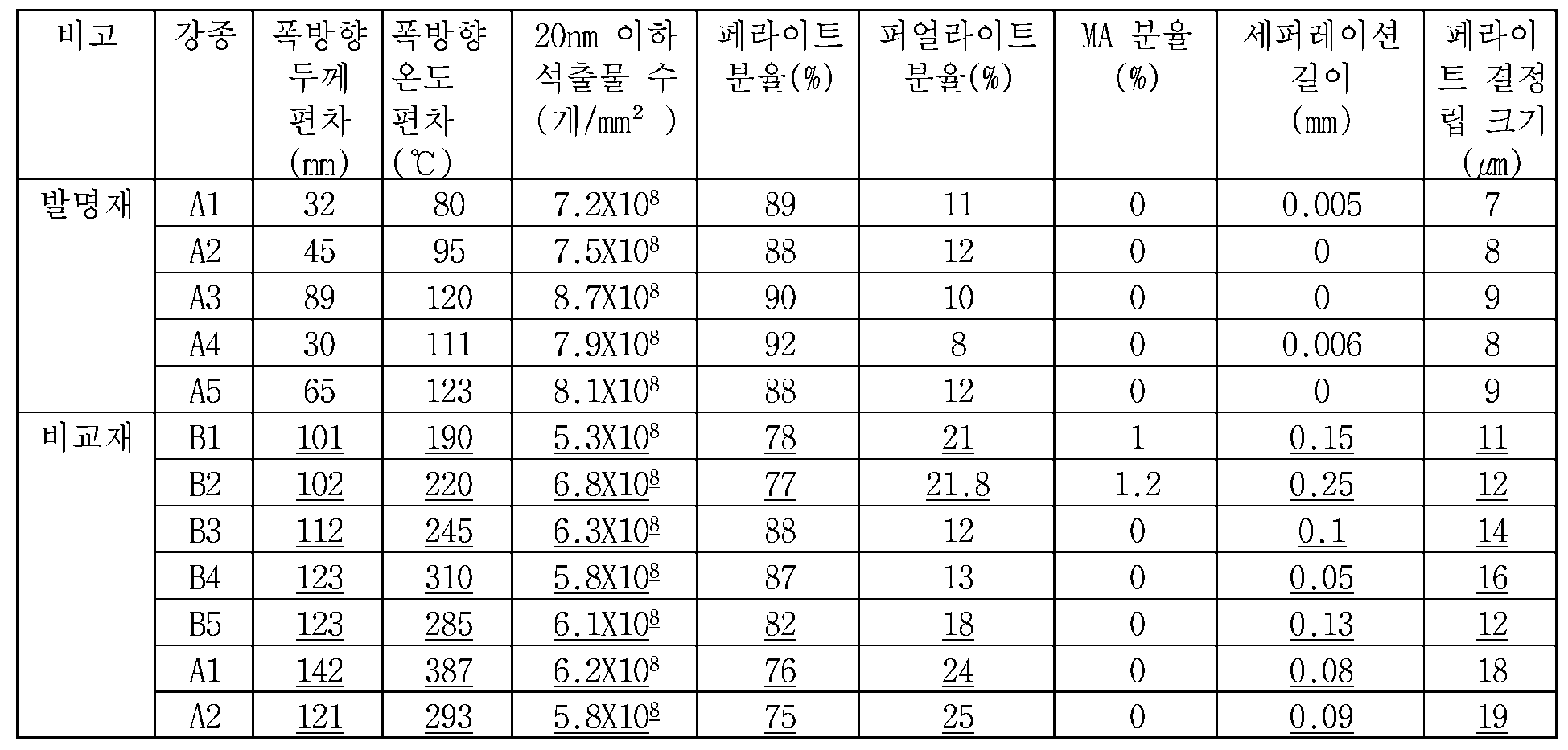

상기 표 1 내지 표 5에 나타난 바와 같이, 본 발명에 부합되는 성분 및 성분범위, 성분 관계식과 제조조건에 따라 제조된 발명재의 경우, 적절한 분율의 다각형 페라이트와 퍼얼라이트를 형성하여 항복강도와 인장강도를 각각 520MPa와 640MPa 이상을 나타냄을 알 수 있다. 또한 에지 히터를 사용하여 양 에지부의 과냉을 방지한 결과 폭방향 항복강도 편차를 35MPa 이하로 억제할 수 있었으며, -60℃에서 충격에너지 95J 이상이 확보됨을 알 수 있다.
Claims (9)
- 중량%로, C: 0.07~0.13%, Si: 0.20~0.50%, Mn: 0.5~0.9%, P: 0.03%이하, S: 0.02%이하, Nb: 0.005~0.03%, Cr: 0.3~0.6%, Ti: 0.005~0.03%, Cu: 0.1~0.35%, Ni: 0.05~0.3%, Mo: 0.01~0.15%, N: 0.007%이하, Ca: 0.001~0.006%, Al: 0.01~0.05%, 나머지는 Fe 및 기타 불가피한 불순물을 포함하고;상기 합금원소들이 다음 관계식[관계식 1]1.6 ≤ (Mo/96)/(P/31) ≤ 6[관계식 2]1.6 ≤ (Ca/S) ≤ 3[관계식 3]3.5 ≤ (3*C/12+Mn/55)*100 ≤ 5을 만족하고; 미세조직은 면적분율로 85% 이상의 다각형 페라이트 및 15% 이하의 퍼얼라이트를 포함하고 상기 다각형 페라이트의 결정립 크기가 10㎛ 이하이고; 그리고 폭방향 항복강도 편차가 35MPa이하인 고강도 고인성 열연강판.
- 제 1 항에 있어서,상기 열연강판은 단위 ㎟ 당 20nm 이하 석출물의 개수가 7×10⁸ 이상인 것을 특징으로 하는 고강도 고인성 열연강판.
- 제 1 항에 있어서,상기 열연강판은 -60℃에서 샤르피 충격시험으로 측정된 충격 인성값이 95J 이상이고 충격시편 파단면에서의 세퍼레이션(separation)이 0.01mm 이하인 것을 특징으로 하는 고강도 고인성 열연강판.
- 제 1 항에 있어서,상기 열연강판은 상온 항복강도가 520MPa 이상이고, 상온 인장강도가 640MPa 이상인 것을 특징으로 하는 고강도 고인성 열연강판.
- 중량%로, C: 0.07~0.13%, Si: 0.20~0.50%, Mn: 0.5~0.9%, P: 0.03%이하, S: 0.02%이하, Nb: 0.005~0.03%, Cr: 0.3~0.6%, Ti: 0.005~0.03%, Cu: 0.1~0.35%, Ni: 0.05~0.3%, Mo: 0.01~0.15%, N: 0.007%이하, Ca: 0.001~0.006%, Al: 0.01~0.05%, 나머지는 Fe 및 기타 불가피한 불순물을 포함하고,상기 합금원소들이 다음 관계식[관계식 1]1.6 ≤ (Mo/96)/(P/31) ≤ 6[관계식 2]1.6 ≤ (Ca/S) ≤ 3[관계식 3]3.5 ≤ (3*C/12+Mn/55)*100 ≤ 5을 만족하는 강 슬라브를 준비하는 단계;상기 강 슬라브를 1100~1300℃의 온도로 가열하고 1160℃ 이상에서 30분 이상 유지한 후 추출하는 단계;상기와 같이 가열되어 추출된 강 슬라브를 900~1000℃의 압연종료온도 및 10%이상의 재결정역 패스당 압하율의 조건으로 1차 열간압연한 다음, 750~870℃의 압연종료온도 및 85%이상의 미재결정역 누적 압하율의 조건으로 2차 열간압연하여 열연강판을 얻는 단계; 및상기 열연강판을 10~50℃/s의 냉각속도로 500~580℃의 냉각종료온도까지 수냉한 후 권취하는 단계를 포함하고, 상기 수냉 시 강재의 중심부와 에지부의 냉각속도차이를 감소시키기 위하여 강판의 양 에지(edge) 부에 열에너지를 부여하는 고강도 고인성 열연강판의 제조방법.
- 제 5 항에 있어서,상기 열간압연은 강판 에지(edge)부와 에지에서 100mm 지점의 두께 편차가 90mm 이하가 되도록 실시되는 것을 특징으로 하는 고강도 고인성 열연강판의 제조방법.
- 제 5 항에 있어서,상기 강판 양 에지(edge)부에의 열에너지 부여는 수냉 시 강판 폭방향 온도 편차가 150℃ 이하가 되도록 수행되는 것을 특징으로 하는 고강도 고인성 열연강판의 제조방법.
- 제 5 항에 있어서,상기 강판의 양 에지(edge) 부에의 열에너지 부여는 에지 히터(edge heater) 및 에지 마스크(edge mask)를 사용하여 수행되는 것을 특징으로 하는 고강도 고인성 열연강판의 제조방법.
- 제 5 항에 있어서,상기 열연강판의 폭방향 항복강도 편차가 35MPa이하이고, -60℃에서 샤르피 충격시험으로 측정된 충격 인성값이 95J 이상이고, 충격시편 파단면에서의 세퍼레이션(separation)이 0.01mm 이하이고, 상온 항복강도가 520MPa 이상이고, 상온 인장강도가 640MPa 이상인 것을 특징으로 하는 고강도 고인성 열연강판의 제조방법.
Priority Applications (4)
| Application Number | Priority Date | Filing Date | Title |
|---|---|---|---|
| JP2020535191A JP7082669B2 (ja) | 2017-12-26 | 2018-09-17 | 高強度高靭性熱延鋼板及びその製造方法 |
| US16/957,939 US11578392B2 (en) | 2017-12-26 | 2018-09-17 | High-strength high-toughness hot-rolled steel sheet and manufacturing method therefor |
| CN201880084502.3A CN111542621B (zh) | 2017-12-26 | 2018-09-17 | 高强度高韧性的热轧钢板及其制造方法 |
| EP18895072.9A EP3733912A4 (en) | 2017-12-26 | 2018-09-17 | HIGH STRENGTH AND STRENGTH HOT ROLLED STEEL SHEET AND ITS MANUFACTURING PROCESS |
Applications Claiming Priority (2)
| Application Number | Priority Date | Filing Date | Title |
|---|---|---|---|
| KR1020170179337A KR102010081B1 (ko) | 2017-12-26 | 2017-12-26 | 고강도 고인성 열연강판 및 그 제조방법 |
| KR10-2017-0179337 | 2017-12-26 |
Publications (2)
| Publication Number | Publication Date |
|---|---|
| WO2019132179A1 true WO2019132179A1 (ko) | 2019-07-04 |
| WO2019132179A8 WO2019132179A8 (ko) | 2020-02-27 |
Family
ID=67063956
Family Applications (1)
| Application Number | Title | Priority Date | Filing Date |
|---|---|---|---|
| PCT/KR2018/010935 WO2019132179A1 (ko) | 2017-12-26 | 2018-09-17 | 고강도 고인성 열연강판 및 그 제조방법 |
Country Status (6)
| Country | Link |
|---|---|
| US (1) | US11578392B2 (ko) |
| EP (1) | EP3733912A4 (ko) |
| JP (1) | JP7082669B2 (ko) |
| KR (1) | KR102010081B1 (ko) |
| CN (1) | CN111542621B (ko) |
| WO (1) | WO2019132179A1 (ko) |
Cited By (1)
| Publication number | Priority date | Publication date | Assignee | Title |
|---|---|---|---|---|
| WO2021161366A1 (ja) * | 2020-02-10 | 2021-08-19 | 日本製鉄株式会社 | ラインパイプ用電縫鋼管 |
Families Citing this family (1)
| Publication number | Priority date | Publication date | Assignee | Title |
|---|---|---|---|---|
| KR20230072050A (ko) * | 2021-11-17 | 2023-05-24 | 주식회사 포스코 | 냉간 성형 후 내충격성이 우수한 고항복비형 고강도강 및 그 제조방법 |
Citations (7)
| Publication number | Priority date | Publication date | Assignee | Title |
|---|---|---|---|---|
| JP2002003985A (ja) * | 2000-06-20 | 2002-01-09 | Nippon Steel Corp | 高温強度に優れた高張力鋼およびその製造方法 |
| JP2004351501A (ja) * | 2003-05-30 | 2004-12-16 | Jfe Steel Kk | 熱延金属板の冷却方法および冷却装置ならびに高張力熱延鋼板およびその製造方法 |
| KR100833035B1 (ko) * | 2006-12-20 | 2008-05-27 | 주식회사 포스코 | 변형능이 우수한 고강도 고인성 라인파이프용 강판 및 그제조방법 |
| JP2010106287A (ja) * | 2008-10-28 | 2010-05-13 | Jfe Steel Corp | 疲労特性に優れた高張力鋼材およびその製造方法 |
| KR101568544B1 (ko) * | 2013-12-25 | 2015-11-11 | 주식회사 포스코 | 중심부에서의 파괴전파 정지특성이 우수한 라인파이프용 고강도 후물 강재 및 그 제조방법 |
| KR101585724B1 (ko) * | 2013-12-24 | 2016-01-14 | 주식회사 포스코 | 중심부 저온 파괴전파 저항성 및 항복비 특성이 동시에 우수한 후물 라인파이프 강재 및 그 제조방법 |
| KR20160077385A (ko) | 2014-12-22 | 2016-07-04 | 주식회사 포스코 | 수소유기균열(hic) 저항성 및 저온인성이 우수한 압력용기용 강재 및 이의 제조방법 |
Family Cites Families (19)
| Publication number | Priority date | Publication date | Assignee | Title |
|---|---|---|---|---|
| JP3039862B1 (ja) | 1998-11-10 | 2000-05-08 | 川崎製鉄株式会社 | 超微細粒を有する加工用熱延鋼板 |
| JP4206642B2 (ja) | 2000-02-23 | 2009-01-14 | Jfeスチール株式会社 | 歪時効硬化特性に優れた高張力熱延鋼板およびその製造方法 |
| TW558569B (en) | 2000-02-23 | 2003-10-21 | Kawasaki Steel Co | High tensile hot-rolled steel sheet having excellent strain aging hardening properties and method for producing the same |
| KR100568363B1 (ko) | 2001-12-26 | 2006-04-05 | 주식회사 포스코 | 용접열영향부 인성이 우수한 페라이트 세립형 용접구조용강 및 그 제조방법 |
| JP4788146B2 (ja) | 2004-03-09 | 2011-10-05 | Jfeスチール株式会社 | 耐時効性に優れた低yr型電縫溶接鋼管用熱延鋼板とその製造方法 |
| KR101125874B1 (ko) | 2004-12-21 | 2012-03-21 | 주식회사 포스코 | 인성이 우수한 고강도 해변용 내후성강의 제조방법 |
| CN100507055C (zh) | 2006-08-31 | 2009-07-01 | 宝山钢铁股份有限公司 | 屈服强度700MPa级耐大气腐蚀钢及其制造方法 |
| US8110292B2 (en) * | 2008-04-07 | 2012-02-07 | Nippon Steel Corporation | High strength steel plate, steel pipe with excellent low temperature toughness, and method of production of same |
| CN102112643B (zh) * | 2008-07-31 | 2013-11-06 | 杰富意钢铁株式会社 | 低温韧性优良的厚壁高强度热轧钢板及其制造方法 |
| JP5776398B2 (ja) | 2011-02-24 | 2015-09-09 | Jfeスチール株式会社 | 低温靭性に優れた低降伏比高強度熱延鋼板およびその製造方法 |
| EP2735622B1 (en) * | 2011-07-20 | 2019-09-04 | JFE Steel Corporation | Low-yield-ratio high-strength hot-rolled steel plate with excellent low-temperature toughness and process for producing same |
| EP2752499B1 (en) | 2011-08-23 | 2016-10-05 | Nippon Steel & Sumitomo Metal Corporation | Thick wall electric resistance welded steel pipe and method of production of same |
| RU2014117498A (ru) | 2011-10-04 | 2015-11-10 | Ведрекс Оод | Экстремальный оптический симулятор стрельбы |
| KR20140104497A (ko) | 2012-01-18 | 2014-08-28 | 제이에프이 스틸 가부시키가이샤 | 코일드 튜빙용 강대 및 그 제조 방법 |
| IN2014MN01980A (ko) | 2012-04-13 | 2015-07-10 | Jfe Steel Corp | |
| KR20160078714A (ko) | 2014-12-24 | 2016-07-05 | 주식회사 포스코 | 대입열 용접열영향부 인성이 우수한 용접구조용 강재 및 그 제조방법 |
| KR101993542B1 (ko) | 2015-03-06 | 2019-09-30 | 제이에프이 스틸 가부시키가이샤 | 고강도 전봉 강관 및 그 제조 방법 |
| CN107406947B (zh) * | 2015-03-25 | 2020-02-14 | 杰富意钢铁株式会社 | 高强度钢板及其制造方法 |
| CN105463324B (zh) * | 2016-01-15 | 2017-09-22 | 宝山钢铁股份有限公司 | 一种厚规格高韧性管线钢及其制造方法 |
-
2017
- 2017-12-26 KR KR1020170179337A patent/KR102010081B1/ko active IP Right Grant
-
2018
- 2018-09-17 WO PCT/KR2018/010935 patent/WO2019132179A1/ko unknown
- 2018-09-17 CN CN201880084502.3A patent/CN111542621B/zh active Active
- 2018-09-17 US US16/957,939 patent/US11578392B2/en active Active
- 2018-09-17 JP JP2020535191A patent/JP7082669B2/ja active Active
- 2018-09-17 EP EP18895072.9A patent/EP3733912A4/en active Pending
Patent Citations (7)
| Publication number | Priority date | Publication date | Assignee | Title |
|---|---|---|---|---|
| JP2002003985A (ja) * | 2000-06-20 | 2002-01-09 | Nippon Steel Corp | 高温強度に優れた高張力鋼およびその製造方法 |
| JP2004351501A (ja) * | 2003-05-30 | 2004-12-16 | Jfe Steel Kk | 熱延金属板の冷却方法および冷却装置ならびに高張力熱延鋼板およびその製造方法 |
| KR100833035B1 (ko) * | 2006-12-20 | 2008-05-27 | 주식회사 포스코 | 변형능이 우수한 고강도 고인성 라인파이프용 강판 및 그제조방법 |
| JP2010106287A (ja) * | 2008-10-28 | 2010-05-13 | Jfe Steel Corp | 疲労特性に優れた高張力鋼材およびその製造方法 |
| KR101585724B1 (ko) * | 2013-12-24 | 2016-01-14 | 주식회사 포스코 | 중심부 저온 파괴전파 저항성 및 항복비 특성이 동시에 우수한 후물 라인파이프 강재 및 그 제조방법 |
| KR101568544B1 (ko) * | 2013-12-25 | 2015-11-11 | 주식회사 포스코 | 중심부에서의 파괴전파 정지특성이 우수한 라인파이프용 고강도 후물 강재 및 그 제조방법 |
| KR20160077385A (ko) | 2014-12-22 | 2016-07-04 | 주식회사 포스코 | 수소유기균열(hic) 저항성 및 저온인성이 우수한 압력용기용 강재 및 이의 제조방법 |
Non-Patent Citations (1)
| Title |
|---|
| See also references of EP3733912A4 |
Cited By (3)
| Publication number | Priority date | Publication date | Assignee | Title |
|---|---|---|---|---|
| WO2021161366A1 (ja) * | 2020-02-10 | 2021-08-19 | 日本製鉄株式会社 | ラインパイプ用電縫鋼管 |
| JPWO2021161366A1 (ko) * | 2020-02-10 | 2021-08-19 | ||
| JP7226595B2 (ja) | 2020-02-10 | 2023-02-21 | 日本製鉄株式会社 | ラインパイプ用電縫鋼管 |
Also Published As
| Publication number | Publication date |
|---|---|
| CN111542621A (zh) | 2020-08-14 |
| JP7082669B2 (ja) | 2022-06-08 |
| KR102010081B1 (ko) | 2019-08-12 |
| EP3733912A1 (en) | 2020-11-04 |
| EP3733912A4 (en) | 2020-11-04 |
| WO2019132179A8 (ko) | 2020-02-27 |
| JP2021509434A (ja) | 2021-03-25 |
| US20210062312A1 (en) | 2021-03-04 |
| KR20190077829A (ko) | 2019-07-04 |
| US11578392B2 (en) | 2023-02-14 |
| CN111542621B (zh) | 2022-05-24 |
Similar Documents
| Publication | Publication Date | Title |
|---|---|---|
| WO2016104975A1 (ko) | Pwht 후 인성이 우수한 고강도 압력용기용 강재 및 그 제조방법 | |
| WO2021091138A1 (ko) | 저온 충격인성이 우수한 고강도 강재 및 그 제조방법 | |
| WO2018074887A1 (ko) | 고강도 철근 및 이의 제조 방법 | |
| WO2018117712A1 (ko) | 저온인성 및 항복강도가 우수한 고 망간 강 및 제조 방법 | |
| WO2018117450A1 (ko) | 저온인성 및 후열처리 특성이 우수한 내sour 후판 강재 및 그 제조방법 | |
| WO2019124945A1 (ko) | 저온에서의 내파괴 특성이 우수한 극지 환경용 고강도 강재 및 그 제조방법 | |
| WO2018117646A1 (ko) | 극저온 충격인성이 우수한 후강판 및 이의 제조방법 | |
| WO2018117614A1 (ko) | 표면부 nrl-dwt 물성이 우수한 극후물 강재 및 그 제조방법 | |
| WO2018004297A1 (ko) | 저항복비 특성 및 저온인성이 우수한 고강도 강판 및 그 제조방법 | |
| WO2020067752A1 (ko) | 구멍확장성이 높은 고강도 냉연강판, 고강도 용융아연도금강판 및 이들의 제조방법 | |
| WO2015099222A1 (ko) | 용접성 및 버링성이 우수한 열연강판 및 그 제조방법 | |
| WO2017105109A1 (ko) | 저온 변형시효 충격특성이 우수한 고강도 강재 및 이의 제조방법 | |
| WO2020111732A1 (ko) | 저온인성과 연신율이 우수하며, 항복비가 작은 후물 고강도 라인파이프용 강재 및 그 제조방법 | |
| WO2012043984A2 (ko) | 수소유기균열 저항성이 우수한 라인 파이프용 강판 및 그 제조 방법 | |
| WO2020111856A2 (ko) | 연성 및 저온 인성이 우수한 고강도 강재 및 이의 제조방법 | |
| WO2016104883A1 (ko) | 연성이 우수한 페라이트계 스테인리스 강재 및 그 제조방법 | |
| WO2019132179A1 (ko) | 고강도 고인성 열연강판 및 그 제조방법 | |
| WO2021117989A1 (ko) | 초고강도 냉연강판 및 이의 제조방법 | |
| WO2020111891A1 (ko) | 저온파괴인성 및 연신율이 우수한 고강도 강판 및 그 제조방법 | |
| WO2021010599A2 (ko) | 강도가 향상된 오스테나이트계 스테인리스강 및 그 제조 방법 | |
| WO2020060051A1 (ko) | 충격 인성이 우수한 페라이트계 스테인리스 열연 무소둔 강판 및 그 제조방법 | |
| WO2022065797A1 (ko) | 연신율이 우수한 고강도 후물 열연강판 및 그 제조방법 | |
| WO2016072679A1 (ko) | 강도와 충격 인성이 우수한 선재 및 그 제조방법 | |
| WO2017111303A1 (ko) | 굽힘 가공성이 우수한 고강도 열연 강판 및 그 제조 방법 | |
| WO2017086745A1 (ko) | 전단가공성이 우수한 고강도 냉연강판 및 그 제조방법 |
Legal Events
| Date | Code | Title | Description |
|---|---|---|---|
| 121 | Ep: the epo has been informed by wipo that ep was designated in this application |
Ref document number: 18895072 Country of ref document: EP Kind code of ref document: A1 |
|
| ENP | Entry into the national phase |
Ref document number: 2020535191 Country of ref document: JP Kind code of ref document: A |
|
| NENP | Non-entry into the national phase |
Ref country code: DE |
|
| ENP | Entry into the national phase |
Ref document number: 2018895072 Country of ref document: EP Effective date: 20200727 |