WO2019131823A1 - 起上台および内視鏡 - Google Patents
起上台および内視鏡 Download PDFInfo
- Publication number
- WO2019131823A1 WO2019131823A1 PCT/JP2018/048001 JP2018048001W WO2019131823A1 WO 2019131823 A1 WO2019131823 A1 WO 2019131823A1 JP 2018048001 W JP2018048001 W JP 2018048001W WO 2019131823 A1 WO2019131823 A1 WO 2019131823A1
- Authority
- WO
- WIPO (PCT)
- Prior art keywords
- elevator
- lever
- endoscope
- raising
- tip
- Prior art date
- Legal status (The legal status is an assumption and is not a legal conclusion. Google has not performed a legal analysis and makes no representation as to the accuracy of the status listed.)
- Ceased
Links
Images


Classifications
-
- A—HUMAN NECESSITIES
- A61—MEDICAL OR VETERINARY SCIENCE; HYGIENE
- A61B—DIAGNOSIS; SURGERY; IDENTIFICATION
- A61B1/00—Instruments for performing medical examinations of the interior of cavities or tubes of the body by visual or photographical inspection, e.g. endoscopes; Illuminating arrangements therefor
- A61B1/00064—Constructional details of the endoscope body
- A61B1/00071—Insertion part of the endoscope body
- A61B1/0008—Insertion part of the endoscope body characterised by distal tip features
- A61B1/00098—Deflecting means for inserted tools
-
- A—HUMAN NECESSITIES
- A61—MEDICAL OR VETERINARY SCIENCE; HYGIENE
- A61B—DIAGNOSIS; SURGERY; IDENTIFICATION
- A61B1/00—Instruments for performing medical examinations of the interior of cavities or tubes of the body by visual or photographical inspection, e.g. endoscopes; Illuminating arrangements therefor
- A61B1/00064—Constructional details of the endoscope body
- A61B1/00071—Insertion part of the endoscope body
- A61B1/0008—Insertion part of the endoscope body characterised by distal tip features
- A61B1/00101—Insertion part of the endoscope body characterised by distal tip features the distal tip features being detachable
-
- A—HUMAN NECESSITIES
- A61—MEDICAL OR VETERINARY SCIENCE; HYGIENE
- A61B—DIAGNOSIS; SURGERY; IDENTIFICATION
- A61B1/00—Instruments for performing medical examinations of the interior of cavities or tubes of the body by visual or photographical inspection, e.g. endoscopes; Illuminating arrangements therefor
- A61B1/00112—Connection or coupling means
- A61B1/00121—Connectors, fasteners and adapters, e.g. on the endoscope handle
-
- A—HUMAN NECESSITIES
- A61—MEDICAL OR VETERINARY SCIENCE; HYGIENE
- A61B—DIAGNOSIS; SURGERY; IDENTIFICATION
- A61B1/00—Instruments for performing medical examinations of the interior of cavities or tubes of the body by visual or photographical inspection, e.g. endoscopes; Illuminating arrangements therefor
- A61B1/00131—Accessories for endoscopes
- A61B1/00137—End pieces at either end of the endoscope, e.g. caps, seals or forceps plugs
-
- A—HUMAN NECESSITIES
- A61—MEDICAL OR VETERINARY SCIENCE; HYGIENE
- A61B—DIAGNOSIS; SURGERY; IDENTIFICATION
- A61B1/00—Instruments for performing medical examinations of the interior of cavities or tubes of the body by visual or photographical inspection, e.g. endoscopes; Illuminating arrangements therefor
- A61B1/00147—Holding or positioning arrangements
- A61B1/00148—Holding or positioning arrangements using anchoring means
-
- A—HUMAN NECESSITIES
- A61—MEDICAL OR VETERINARY SCIENCE; HYGIENE
- A61B—DIAGNOSIS; SURGERY; IDENTIFICATION
- A61B90/00—Instruments, implements or accessories specially adapted for surgery or diagnosis and not covered by any of the groups A61B1/00 - A61B50/00, e.g. for luxation treatment or for protecting wound edges
- A61B90/70—Cleaning devices specially adapted for surgical instruments
-
- G—PHYSICS
- G02—OPTICS
- G02B—OPTICAL ELEMENTS, SYSTEMS OR APPARATUS
- G02B23/00—Telescopes, e.g. binoculars; Periscopes; Instruments for viewing the inside of hollow bodies; Viewfinders; Optical aiming or sighting devices
- G02B23/24—Instruments or systems for viewing the inside of hollow bodies, e.g. fibrescopes
-
- A—HUMAN NECESSITIES
- A61—MEDICAL OR VETERINARY SCIENCE; HYGIENE
- A61B—DIAGNOSIS; SURGERY; IDENTIFICATION
- A61B90/00—Instruments, implements or accessories specially adapted for surgery or diagnosis and not covered by any of the groups A61B1/00 - A61B50/00, e.g. for luxation treatment or for protecting wound edges
- A61B90/70—Cleaning devices specially adapted for surgical instruments
- A61B2090/701—Cleaning devices specially adapted for surgical instruments for flexible tubular instruments, e.g. endoscopes
Definitions
- the present invention relates to an elevator and an endoscope.
- An endoscope having an elevator at the tip of a channel passing through the interior of the insert is used.
- the elevator is used in bending a treatment tool or the like passed through a channel to guide it in a desired direction.
- Patent Document 1 An endoscope in which a wall is provided between a raising wire for moving a raising base and the raising base is disclosed.
- it aims at providing an elevator etc. which make cleaning of an endoscope easy by removing after an endoscopic examination.
- the elevator comprises a lever that is rotatably provided at the tip of the insertion portion, and a pivoting portion that pivots the lever.
- an elevator or the like can be provided that facilitates cleaning of the endoscope by removing it after endoscopic examination.
- FIG. 21 is a cross-sectional view of the insertion portion taken along line XXI-XXI of FIG. 20.
- FIG. 5 is a cross-sectional view of the insertion portion taken along line XXII-XXII of FIG. 4; It is sectional drawing of the insertion part which raised the raising stand. It is the perspective view which saw the cap for endoscopes of Embodiment 2 from the attachment side to an endoscope.
- FIG. 10 is a perspective view of the elevator of the second embodiment.
- FIG. 10 is a perspective view of a pedestal of Embodiment 2;
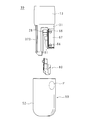
- FIG. 1 is an external view of an endoscope.
- the endoscope 10 of the present embodiment is a flexible endoscope for the upper digestive tract.
- the endoscope 10 has an operation unit 20 and an insertion unit 30.
- the operation unit 20 has a raising control lever 21, a channel inlet 22 and a bending knob 23.
- the operation unit 20 is connected to a video processor, a light source device, a display device, and the like (not shown).
- the insertion unit 30 is long, and one end thereof is connected to the operation unit 20.
- the insertion unit 30 includes the flexible portion 12, the bending portion 13, and the endoscope cap 50 in order from the operation unit 20 side.
- the soft portion 12 is soft.
- the bending portion 13 bends in response to the operation of the bending knob 23.
- the endoscope cap 50 covers the rigid distal end portion 31 (see FIG. 2) continuous with the bending portion 13.
- the longitudinal direction of the insertion portion 30 is referred to as an insertion direction.
- the side closer to the operation unit 20 along the insertion direction is referred to as the operation unit side, and the side farther from the operation unit 20 is referred to as the tip side.
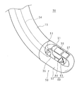
- FIG. 2 is a perspective view of the distal end of the insertion portion 30.
- FIG. FIG. 3 is an explanatory view showing a state in which the treatment instrument distal end portion 41 protrudes from the distal end of the insertion portion 30. As shown in FIG. The configuration of the endoscope 10 according to the present embodiment will be described using FIGS. 1 to 3.
- the distal end portion 31 disposed at the distal end of the bending portion 13 has an observation window 36 and an illumination window 37 aligned along the insertion direction on one side.
- the illumination window 37 is disposed on the tip side of the observation window 36.
- the distal end portion 31 has a channel outlet 35 on the operation unit side on the other side.
- a raising portion 83 is disposed on the distal end side of the channel outlet 35.
- the cover 52 covering the distal end portion 31 has a substantially rectangular window portion 53 in a portion corresponding to the observation window 36, the illumination window 37 and the raising portion 83.
- the side on the operation unit side of the window portion 53 has a step-like shape in which the rising portion 83 side is positioned at the operation portion side and the observation window 36 side is positioned at the tip end side.
- the illumination window 37 emits illumination light emitted from a light source device (not shown). Through the observation window 36, it is possible to optically observe the area illuminated by the illumination light.
- the endoscope 10 of the present embodiment is a so-called side-view type in which the visual field direction in which optical observation is possible is a direction intersecting the insertion direction.
- the endoscope 10 may be a front oblique view type in which the visual field direction is slightly inclined toward the distal end side, or a rear oblique vision type in which the visual field direction is slightly inclined toward the operation unit.
- the channel inlet 22 and the channel outlet 35 are connected by a channel 34 passing through the inside of the flexible portion 12 and the bending portion 13.
- the treatment tool tip 41 protrudes while being gently bent on the raising portion 83.
- a lever 60 moves as described later, and the raising stand 80 moves in conjunction with the lever 60.
- the movement of the elevator 80 causes the treatment tool tip 41 on the elevator 80 to bend toward the operation unit 20 as shown by the arrow and the two-dot chain line in FIG. 1 and FIG. 3.
- the movement of the treatment instrument tip 41 is photographed by an imaging device (not shown) or the like through the observation window 36 and displayed on a display (not shown).
- the treatment instrument 40 is a treatment instrument such as, for example, a high-frequency knife, forceps or an imaging tube.
- the device to be inserted into the channel 34 is not limited to the treatment device.
- a device for observation such as an ultrasonic probe or an ultrafine endoscope may be inserted into the channel 34 and used.
- the instrument for observation is also described as the treatment tool 40.
- the movement of the elevator 80 may be expressed as “the elevator 80 raises” in the following description.
- the bending of the treatment instrument distal end portion 41 may be expressed as “the treatment instrument 40 rises” by being pushed by the raising platform 80 which has been raised.
- the degree of raising of the treatment tool 40 can be adjusted by operating the raising operation lever 21.
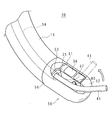
- FIG. 4 is a front view of the tip of the insertion portion 30.
- the cover 52 has a rectangular recess 48 near the open end 56. Each side of the recess 48 falls substantially perpendicularly from the surface of the cover 52.
- the concave portion 48 is thinner than other portions in the circumferential direction of the cover 52, and is a portion that is easily bent when an external force is applied by pressing with a finger or the like.
- the recess 48 is an example of the flexible portion in the present embodiment.
- the endoscope cap 50 and the elevator 80 can be attached to and detached from the insertion portion 30.
- the endoscope cap 50 has a cover 52 which is an exterior member. The details of the configuration of the endoscope cap 50 and the elevator 80 will be described later.
- FIG. 5 is a front view illustrating a state in which the endoscope cap 50 and the elevator 80 are removed from the tip of the insertion portion 30.
- FIG. 6 is a rear view illustrating a state in which the endoscope cap 50 and the elevator 80 are removed from the tip of the insertion portion 30.
- FIG. 5 is a front view illustrating a state in which the endoscope cap 50 and the elevator 80 are removed from the tip of the insertion portion 30.
- FIG. 6 is a rear view illustrating a state in which the endoscope cap 50 and the elevator 80 are removed from the tip of the insertion portion 30.
- the user holds the bending portion 13 with one hand and picks the cover 52 with the two fingers of the other hand. At this time, when one of the two fingers presses the recess 48, the other finger naturally presses the area indicated by P in FIG.
- the user can press the cover 52 with two fingers and lightly deform it, and then pull it toward the distal end side to remove the endoscope cap 50 from the insertion portion 30 as described later. Thereafter, the user can remove the elevator 80 from the insertion portion 30 by pulling the elevator 80 to the tip side using a finger or the like.
- FIG. 7 is a perspective view of the distal end of the insertion portion 30 with the endoscope cap 50 and the elevator 80 removed.
- the configuration of the distal end of the insertion portion 30 will be described using FIGS. 5 to 7.
- the distal end portion 31 has a substantially cylindrical shape, and is divided into an optical storage portion 33 and a lever chamber 69 by a groove provided from the distal end side toward the operation portion at a position shifted from the center.
- the channel outlet 35 opens at the bottom of the groove. In the vicinity of the channel outlet 35, a bent portion 27 is provided. The shape of the bending portion 27 will be described later.
- the tip portion 31 has a first flat portion 321 formed by notching a part of the circumferential surface.
- a third engaging portion 29 is provided on a portion of the first flat portion 321 along the bottom of the groove separating the optical accommodation portion 33 and the lever chamber 69.
- the third engaging portion 29 is an oval recess.
- the distal end portion 31 has a fourth engaging portion 28 (see FIG. 6) on the back side of the third engaging portion 29.
- the fourth engaging portion 28 is a rectangular recess.
- An observation window 36 and an illumination window 37 are disposed on the side of the first flat portion 321 on the side of the optical storage unit 33.
- a nozzle 38 for injecting water and air to the observation window 36 for cleaning is provided on the operation unit side of the observation window 36.
- the lever chamber 69 is hollow and is covered with a rectangular thin plate-like lever chamber lid 67 along the outer peripheral surface of the distal end portion 31.
- the lever chamber lid 67 is fixed at four corners by a lid screw 66.
- the lid screw 66 is an example of the fixing member of the present embodiment.
- the lever chamber 69 has a support wall 68 on the optical storage unit 33 side.
- the elevator connecting portion 61 protrudes from the support wall 68 toward the optical storage portion 33.
- the elevator connection 61 is an axis of a rectangular cross section. The elevator connecting portion 61 will be described later.
- FIG. 8 is a perspective view of the tip of the insertion portion 30 with the endoscope cap 50, the elevator 80 and the lever chamber lid 67 removed.
- a lever 60 is provided inside the lever chamber 69.
- the lever 60 has a wire fixing portion 65 at one end, and a lever shaft 63 (see FIG. 17) and an elevator connection portion 61 at the other end as described later.
- the lever 60 is rotatably supported by a hole provided in the support wall 68.
- the wire fixing portion 65 is connected to the end of the raising wire 24.
- the raising wire 24 is connected to the raising operation lever 21 (see FIG. 1) through the insertion portion 30. More specifically, the raising wire 24 is inserted into a guide tube (not shown) having an inner diameter slightly larger than the outer diameter of the raising wire 24. A guide tube (not shown) penetrates the insertion portion 30 in the longitudinal direction. Therefore, the tip of the raising wire 24 advances and retracts in conjunction with the operation of the raising operation lever 21.
- the lever 60 is pivoted around the lever shaft 63 by being pushed and pulled by the tip of the raising wire 24.
- the raising wire 24 is an example of the rotation part of this embodiment.
- the raising wire 24 is remotely operated by the raising operation lever 21.
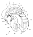
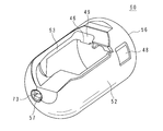
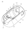
- FIG. 9 is a perspective view of the endoscope cap 50 as viewed from the attachment side to the endoscope 10.
- FIG. 10 is a perspective view of the endoscope cap 50 viewed from the bottom side of the cover 52.
- the endoscope cap 50 has a cover 52 and a pedestal 70.
- the cover 52 is a bottomed cylindrical type having an opening at one end. As described above, the opening at one end of the cover 52 is referred to as an open end 56.
- the cover 52 has the window portion 53 in the cylindrical portion.
- the window portion 53 is opened at substantially one entire length of the circumferential surface of the cover 52.
- the cover 52 has a pedestal groove 45 extending from the open end 56 toward the bottom on the inner surface facing the window 53.
- a pedestal 70 is fixed to the pedestal groove 45. The pedestal 70 will be described later.
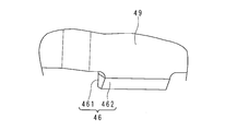
- the cover 52 has a plate-like protrusion 49 that protrudes inward along the edge on the open end 56 side of the window 53. At a part of the tip of the protrusion 49, a first engagement portion 46 is provided so as to protrude inward.
- FIG. 11 is an enlarged perspective view of the first engagement portion 46. As shown in FIG. FIG. 11 is an enlarged view of a portion A of FIG. The shape of the first engagement portion 46 will be described using FIGS. 9 to 11.
- the first engaging portion 46 has a first wedge surface 461 on the bottom side and a second wedge surface 462 on the open end 56 side.
- the first wedge surface 461 is continuous with the bottom surface of the protrusion 49 and is a flat surface along the edge of the window 53.
- the second wedge surface 462 is a flat surface that is inclined with respect to the axial length direction of the cylindrical portion, with the inner side at the bottom side and the outer side at the open end 56 side.
- FIG. 12 is a perspective view of the elevator 80. As shown in FIG. FIG. 13 is a front view of the elevator 80. As shown in FIG. FIG. 14 is a side view of the elevator 80. As shown in FIG. The configuration of the elevator 80 will be described with reference to FIGS. 12 to 14.
- the elevator 80 has a substantially L-shaped rising portion 83.
- the raising portion 83 has a first raising portion 831 having a spoon-like depression 84 on one surface, and a second protruding from the end of the first raising portion 831 on the same side as the plane having the depression 84 of the first raising portion 831. And a raising portion 832.
- a lever connecting portion 81 is provided at an end of the second rising portion 832.
- the lever connection portion 81 is a U-shaped groove that opens toward the end of the second raising portion 832.
- An edge of the opening of the lever connecting portion 81 that is, the opening edge, is provided with a lever retaining portion 812 that protrudes inward.
- One end of the lever connecting portion 81 is covered by a plate-like flange 85.
- the elevator shaft 82 projects from the opposite surface of the flange 85.
- the elevator shaft 82 projects from one surface of the flange 85, and the raising portion 83 projects from the other surface of the flange 85 in the direction intersecting the central axis of the elevator shaft 82.
- a lever connecting portion 81 is provided on the proximal end side of the rising portion 83.
- a non-slip portion 833 formed of a plurality of shallow depressions is provided on the outer side of the first raising portion 831, that is, the surface adjacent to the depression portion 84.
- the shape of the recess is circular, but may be a groove or any other shape.
- the lever connecting portion 81 is disposed to sandwich the central axis of the elevator base shaft 82.
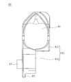
- FIG. 15 is a perspective view of the pedestal 70.
- the configuration of the pedestal 70 will be described using FIG.
- the pedestal 70 has a rectangular plate-like base portion 95 and a substantially rectangular plate-like first wall 77 extending along the longitudinal direction of the base portion 95 from the support foot standing up from the longitudinal central portion of the base portion 95. Further, from the base portion 95, a substantially rectangular plate-like second wall 78 rises in parallel with the first wall 77. The first wall 77 and the second wall 78 are separated in the width direction of the base portion 95.
- a rectangular plate-shaped third wall 79 bridging the first wall 77 and the second wall 78 is connected.
- a first fixing projection 73 is provided on the third wall 79 on the surface opposite to the first wall 77.
- the first fixing protrusion 73 is a cylindrical protrusion having a split groove.
- the first fixing projection 73 has a one-fold thick retaining at the end.
- the base portion 95 has a thick plate portion 741 thicker than the other portions on the side of the third wall 79 in the longitudinal direction and the side of the first wall 77 in the width direction.
- the tip of the thick plate portion 741 is chamfered.
- the base portion 95 has, at an end opposite to the third wall 79, a second engaging portion 72 which rises in a substantially semicircular shape over the entire width.
- the width of the base portion 95 corresponds to the pedestal groove 45.
- the first wall 77 has an elevator mounting groove 761.
- the elevator mounting groove 761 is a substantially U-shaped groove having an opening at an end portion on the root side of the first wall 77 and extending in parallel with the base portion 95.
- the groove width of the elevator mounting groove 761 corresponds to the diameter of the elevator shaft 82.
- FIG. 16 is a cross-sectional view of the endoscope cap 50 taken along line XVI-XVI in FIG.
- the XVI-XVI cross section is a cross section that cuts the first wall 77 in the thickness direction along the longitudinal direction of the insertion portion 30.
- the configuration of the endoscope cap 50 will be described with reference to FIGS. 9 to 11, 15 and 16.
- a pedestal fixing hole 57 is provided at the bottom of the cover 52.
- the pedestal fixing hole 57 is a stepped through hole having a large diameter portion on the side of the outer surface of the cover 52.
- the small diameter portion of the pedestal fixing hole 57 has a tapered shape expanding toward the inner surface of the cover 52.
- the inner diameter of the pedestal fixing hole 57 corresponds to the outer diameter of the first fixing projection 73.
- the cover 52 has a second fixing projection 58 on the inner surface.
- the second fixing projection 58 is a projection that protrudes from the end of the pedestal groove 45 toward the opening end portion 56.
- the distance between the second fixing projection 58 and the bottom of the pedestal groove 45 corresponds to the thickness of the thick plate portion 741.
- the first fixing protrusion 73 elastically deforms and passes through the small diameter portion of the pedestal fixing hole 57. After the retainer of the first fixing projection 73 passes through the small diameter portion of the pedestal fixing hole 57, the first fixing projection 73 elastically returns. The second fixing projection 58 and the thick plate portion 741 are engaged. Thus, the pedestal 70 and the cover 52 are fixed. An adhesive may be applied to the pedestal groove 45 or the like, and the pedestal 70 and the cover 52 may be adhered and fixed.
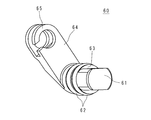
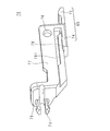
- FIG. 17 is a perspective view of the lever 60.
- the lever 60 has a lever shaft 63 at one end and a wire fixing portion 65 at the other end. From one end face of the lever shaft 63, a raising block connecting portion 61, which is an axis of a rectangular cross section, protrudes in the same direction as the central axis of the lever shaft 63.
- a plate-like portion connecting the lever shaft 63 and the wire fixing portion 65 will be referred to as a rotational connection portion 64.
- the pivot connection portion 64 protrudes from the end of the lever shaft 63 opposite to the elevator connection portion 61 in a direction intersecting the central axis of the lever shaft 63. As shown in FIG. 8, the pivot connection portion 64 pivots within the lever chamber 69.
- the lever shaft 63 is inserted into a hole provided in the support wall 68 from the side of the lever chamber 69, and the lever 60 is rotatably supported in a state where the elevator connecting portion 61 is directed to the optical storage portion 33.
- the hollow lever chamber 69 is watertightly sealed by the O-ring 62 and the lever chamber lid 67.
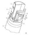
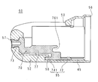
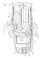
- FIG. 18 is a cross-sectional view of the tip of the insertion portion 30 with the endoscope cap 50 removed.
- FIG. 18 is a cross section taken along line XVI-XVI of FIG. 5 as in FIG. 16 and shows a state in which the elevator 80 is attached to the tip of the insertion portion 30.
- the elevator connecting portion 61 described using FIG. 7 and the lever connecting portion 81 described using FIG. 12 are engaged.
- the endoscopic cap 50 described with reference to FIG. 16 is placed on the elevator 80 and the distal end portion 31 from the left side of FIG. 18 and fixed.
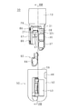
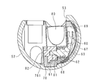
- FIG. 19 is a cross-sectional view of the insertion portion 30 taken along line XIX-XIX in FIG.
- the XIX-XIX cross section is a cross section in which the insertion portion 30 is cut in the longitudinal direction at the position of the elevator connection 61.
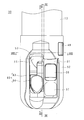
- FIG. 20 is a cross-sectional view of the insertion portion 30 taken along line XX-XX in FIG.
- the XX-XX cross section is a cross section which cuts the insertion portion 30 in the longitudinal direction at the position of the elevator shaft 82.
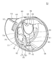
- FIG. 21 is a cross-sectional view of the insertion portion 30 taken along line XXI-XXI of FIG.
- the XXI-XXI cross section is a cross section perpendicular to the longitudinal direction of the insertion portion 30 at the position of the elevator shaft 82.
- the configuration for fixing the elevator 80 and the endoscope cap 50 to the distal end of the insertion portion 30 will be described using FIGS. 19 to 21.
- the endoscope cap 50 has the open end 56 directed to the tip 31 side. As shown in FIG. 19, the first engagement portion 46 of the inner surface of the endoscope cap 50 and the third engagement portion 29 of the distal end portion 31 are engaged. In the engagement portion, the first wedge surface 461 and the surface on the operation portion side of the third engagement portion 29 are in contact with each other.
- the second engagement portion 72 of the inner surface of the endoscope cap 50 and the fourth engagement portion 28 of the distal end portion 31 are engaged.
- the endoscope cap 50 is fixed to the distal end portion 31 by engaging with the distal end portion 31 at two opposing positions on the inner surface.
- An elevator base connecting portion 61 which is an axis of a rectangular cross section is inserted into the U-shaped grooved lever connecting portion 81. Thereby, the lever 60 and the raising stand 80 are engaged. Due to the action of the lever retaining portion 812 provided at the edge of the opening of the lever connecting portion 81, the elevator connecting portion 61 does not come off the lever connecting portion 81.
- the lever retaining portion 812 is an example of the elevator fixing portion in the present embodiment.
- the elevator mounting groove 761 and the elevator shaft 82 are engaged.
- the elevator 80 is supported on both sides by the elevator mounting groove 761 and the elevator connecting portion 61.
- the lever shaft 63 and the elevator shaft 82 are coaxial.
- the elevator 80 smoothly rotates around the lever shaft 63 and the elevator shaft 82.
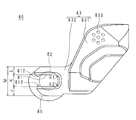
- FIG. 22 is a cross-sectional view of the insertion portion 30 taken along line XXII-XXII of FIG.
- a second flat portion 322 and a third flat portion 323 are provided on the outer side of the optical storage portion 33.
- the second flat portion 322 and the third flat portion 323 are formed by notching a part of the circumferential surface of the distal end portion 31 flat.
- the second flat portion 322 and the third flat portion 323 are continuous at an angle.
- the recess 48 is disposed at a position corresponding to the first cavity 93.
- the cover 52 is made thin by indenting the inner surface of the cylindrical portion.
- the inner surface of the thin portion of the cover 52 and the lever chamber lid 67 face each other with a space therebetween to form a second hollow portion 94.
- the head of the lid screw 66 is disposed in the second hollow portion 94. That is, the second hollow portion 94 is a space for accommodating the head of the lid screw 66 which is a fixing member for fixing the lever chamber lid 67.
- the concave portion 48 is a thin portion which is thinner than the other portions in the circumferential direction of the cover 52, and is a flexible portion which is easily bent by pressing with a finger or the like.
- the user can easily deform the endoscope cap 50 by pressing with a finger. By this deformation, the engagement between the first engagement portion 46 and the third engagement portion 29 and the engagement between the second engagement portion 72 and the fourth engagement portion 28 are released.
- the elevator shaft 82 is disengaged from the elevator mounting groove 761 by the user pulling the endoscope cap 50 toward the distal end while pressing it. Thus, the user can remove the endoscope cap 50 from the insertion portion 30.
- the user can remove the elevator 80 from the insertion portion 30 by holding the elevator 80 with a finger or the like and pulling it toward the tip end. Since the non-slip portion 833 is provided at the picking position, it is difficult to slip, and the user can easily remove the elevator 80.
- a procedure for attaching the elevator 80 and the endoscope cap 50 to the tip of the insertion portion 30 will be described.
- the user grips the non-slip portion 833 of the elevator 80 with a finger or the like.
- the user aligns the elevator joint 61 with the lever joint 81.
- the user inserts the elevator 80 from the distal end side of the insertion portion 30 and presses the lever connecting portion 81 against the elevator connecting portion 61.
- the elevator 80 is elastically deformed to increase the distance between the lever retaining portions 812.
- the elevator connection 61 enters the back of the lever connection 81 through the space between the lever retaining portions 812.
- the elevator 80 elastically returns, and the distance between the lever retaining portions 812 returns to the original.
- the elevator connection portion 61 and the lever connection portion 81 are engaged, and the elevator connection portion 61 is not disengaged from the lever connection portion 81.
- the user can attach the elevator 80 to the tip of the insertion portion 30.
- the user aligns the position of the endoscopic cap 50 in the circumferential direction with respect to the distal end portion 31 with the window portion 53 and the recess portion 84 as marks.
- the user pushes the endoscope cap 50 into the tip of the insertion portion 30.
- the first engaging portion 46 is at the tip 31. It is hard to get caught.
- the first engagement portion 46 is pushed into the third engagement portion 29 while being elastically deformed.
- the first engagement portion 46 elastically returns to engage with the third engagement portion 29 when the first wedge surface 461 enters the third engagement portion 29.
- the second engagement portion 72 is a protrusion that bulges in a substantially semicircular shape, it is easily pushed into the inside of the fourth engagement portion 28.
- the second engagement portion 72 is also pushed into the fourth engagement portion 28 while being elastically deformed. When the second engaging portion 72 enters the fourth engaging portion 28, it elastically returns to engage with the fourth engaging portion 28.
- the user can easily attach the endoscope cap 50 to the distal end of the insertion portion 30.
- the tubular channel 34 is connected to a channel outlet 35 provided at the tip 31.
- the channel outlet 35 is flared toward the window 53.
- a bent portion 27 which gently projects toward the tip end is provided.
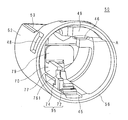
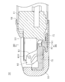
- FIG. 23 is a cross-sectional view of the insertion portion 30 in which the elevator 80 is raised.
- FIG. 23 shows the same cross section as FIG. The configuration for raising the elevator 80 will be described with reference to FIGS. 7, 8, 17, 19, 21 and 23.
- the lever shaft 63 is inserted into the through hole provided in the support wall 68 from the side of the lever chamber 69, and the elevator connection portion 61 protrudes to the opposite side of the support wall 68 as shown in FIG.
- the lever chamber 69 is watertightly sealed by the O-ring 62 and the lever chamber lid 67. Therefore, no body fluid or the like adheres to the inside of the lever chamber 69 and the path of the raising wire 24 while the endoscope 10 is in use.
- the elevator 80 is housed inside the cover 52.
- the recess 84 is disposed at a position where the treatment instrument tip 41 projecting from the channel outlet 35 can be gently bent in the upward direction of FIG.
- the lever 60 pivots about the lever shaft 63.
- the elevator connecting part 61 rotates integrally with the lever shaft 63.
- the lever shaft 63 and the elevator shaft 82 are coaxial. Since the elevator connecting part 61 is connected to the lever connecting part 81, the elevator 80 also rotates integrally with the lever 60. As a result, the distance between the elevator 80 and the window 53 changes.
- FIG. 23 shows a state in which the elevator 80 is rotated and raised.
- the treatment instrument tip 41 projecting from the channel outlet 35 is lifted by being pushed by the elevator 80.
- the treatment instrument distal end portion 41 is pushed toward the operation portion side by the edge on the distal end side of the depression portion 84 from the state of being pressed against the distal end of the bending portion 27.
- the endoscope 10 is stored in a state in which the elevator 80 and the endoscope cap 50 are removed and the cleaning and the like are performed.
- a state in which the elevator 80 and the endoscope cap 50 are enclosed in a sterilization pack one by one or one by one respectively and then put into a paper box in units of 10 units or 10 pairs and then subjected to electron beam sterilization Provided by It is desirable that the number of elevators 80 and the number of endoscopic caps 50 put in a paper box be the minimum sales unit, that is, the minimum unit sold to the user at one time.
- the materials of the cover 52 and the pedestal 70, which are components of the endoscope cap 50, and the material of the elevator 80 are resistant to electron beam sterilization, such as radiation resistant polyetheretherketone or polycarbonate. Is a high material.
- the user takes out the elevator 80 from the sterile pack.
- the user mounts the elevator 80 on the endoscope 10 according to the above-mentioned procedure. Thereafter, the user removes the endoscopic cap 50 from the sterile pack.
- the user attaches the endoscope cap 50 to the insertion portion 30 according to the above-described procedure.
- the user lightly pulls the endoscope cap 50 or the like to confirm that the endoscope cap 50 is firmly fixed to the distal end of the insertion portion 30.
- the user inserts the insertion unit 30 from the mouth of the person to be examined. While observing the video taken through the observation window 36, the user guides the tip of the insertion unit 30 to the target site.
- the user inserts a treatment tool 40 or the like according to the purpose from the channel inlet 22. After confirming that the treatment instrument distal end portion 41 protrudes from the distal end of the insertion portion 30 and is positioned near the target site, the user operates the raising operation lever 21 to guide the treatment instrument distal end portion 41 to the target site . After performing the necessary treatment and the like, the user removes the treatment tool 40 from the channel 34. The user removes the endoscope 10 from the subject to be examined and ends the examination or treatment.
- the user After the examination or treatment, the user removes the endoscope cap 50 from the endoscope 10 by pulling the cover 52 while pressing the cover 52 with two fingers as described above.
- the elevator 80 remains at the tip of the insertion portion 30.
- the user grips the remaining elevator 80 with a finger or the like and pulls it to the tip side.
- the lever connecting portion 81 elastically deforms, and the spacing between the lever retaining portions 812 increases, whereby the elevator 80 is disengaged from the elevator connecting portion 61.
- the user performs processing such as cleaning on the endoscope 10 after removing the endoscope cap 50 and the elevator 80 in preparation for the next use.
- the elevator connecting part 61 used when fixing the elevator 80 is exposed at the tip 31 as shown in FIG.
- the endoscope 10 does not require a special cleaning operation or the like for cleaning a complex structure in the vicinity of the elevator 80. As described above, since no body fluid or the like adheres to the inside of the lever chamber 69 and the path of the raising wire 24 during use of the endoscope 10, the cleaning operation of these parts is also unnecessary.
- the endoscope 10 with the elevator, which has a short processing time between cases and can be operated efficiently. According to the present embodiment, the operability at the start of the endoscopic inspection procedure is improved, that is, the operation of attaching the elevator 80 and the cap 50 for the endoscope to the endoscope 10 is facilitated, and the endoscope 10 Can be compatible with the ease of cleaning.
- the elevator 80 When the stress generated in the H portion exceeds the yield stress of the elevator 80, the elevator 80 is largely deformed, and the treatment tool tip 41 can not be lifted. Therefore, it is necessary to configure the elevator 80 so that the stress generated in the H portion when raising the treatment tool tip 41 does not exceed the yield stress.
- the stress generated in the H portion varies depending on the thickness and hardness of the treatment tool 40 used.
- the stress generated in the H portion is also influenced by various factors such as the shape of the insertion portion 30 at the time of raising and the projection length of the treatment instrument tip portion 41.
- an elevator 80 suitable for the endoscope 10 used for various diagnoses and treatments of the pancreatobiliary region can be provided.
- the lift 80 it is further desirable for the lift 80 to use a material having a tensile yield stress of 50 megapascals or more. It is further desirable for the elevator 80 to use a material having a tensile yield stress of 55 MPa or more. For the lift 80, a material having a higher tensile yield stress may be used.
- the upper limit of the tensile yield stress of the material used for the lift 80 is the upper limit of any material from which the lift 80 can be made, for example 500 megapascals.
- the tensile yield stress of the material is determined according to JIS (Japan Industrial Standard) K7161-2: 2014 (ISO (International Standard Organization) 527-2: 2012) “Plastic-Determination of tensile properties. Part 2: Evaluation based on “Test conditions for molding, extrusion and cast plastic”.
- the groove width of the U-shaped grooved lever connecting portion 81 is indicated by K
- the thickness of the wall on the side of the recess 84 is indicated by L
- the thickness of the wall opposite to the recess 84 is denoted by J
- J the sum of K and L is denoted by M.
- M be 5 mm or less in order to prevent the diameter of the tip of the endoscope 10 from becoming large. More preferably, M is less than or equal to 4.5 millimeters.
- J and L be 1.3 mm or more in order to prevent the elevator 80 from being damaged. More desirably, J and L are at least 1.4 millimeters.
- the inner surface of the lever connection portion 81 have a roundness indicated by a radius R1 and a radius R2 in FIG.
- the radius R1 and the radius R2 are desirably 0.7 millimeters or more. It is further desirable that the radius R1 and the radius R2 be 0.9 mm or more.
- the endoscope 10 includes the elevator 80 and is a side view type, and therefore, is suitable for diagnosis and treatment of the duodenum and the pancreatobiliary region.
- the endoscope 10 of the present embodiment is suitable.
- the treatment instrument 40 is introduced into the duodenal papilla on the duodenal wall, the pancreatic duct opening in the duodenal papilla and the common bile duct, and the like for treatment and the like.
- the side-viewing endoscope 10 may be called a side-viewing endoscope.
- the endoscope 10 suitable for diagnosis and the like of the duodenum and the pancreatobiliary region may be referred to as a duodenum endoscope.
- the pedestal 70 and the cover 52 are separate bodies, their shapes are simple. Therefore, it can be manufactured inexpensively by, for example, injection molding or the like.
- the user may select and use the endoscope cap 50 having a specification according to the procedure from a plurality of types of endoscope caps 50 having different specifications. For example, when using a combination of expensive and precise instruments such as an ultrasonic probe or an extra-fine endoscope, the pivotable range of the elevator 80 is restricted to prevent breakage of the instrument due to excessive bending.
- the depressed portion 84 provided on the elevator base 80 functions to hold the treatment instrument tip 41 and to make it less likely to shake laterally.
- the user may select and use the elevator 80 of the specification according to the procedure from the plurality of types of elevators 80 having different shapes of the recess portion 84. For example, in a procedure requiring precise operation of a thin treatment tool 40 such as a guide wire, an elevator 80 provided with a recess 84 suitable for the thin treatment tool 40 is used.
- the endoscope 10 may be a so-called ultrasound endoscope provided with an ultrasound transducer at its tip. In this case, it is desirable that the endoscope cap 50 have a hole at the bottom through which the ultrasonic transducer is inserted.
- the endoscope 10 may be an endoscope for the lower digestive tract.
- the endoscope 10 may be a so-called rigid endoscope provided with a rigid insertion portion 30.
- the endoscope 10 may be a so-called industrial endoscope which is used for inspection of an engine, piping and the like.
- Endoscope cap 50 and elevator 80 of the present embodiment are both so-called single-use, and are discarded after being used once.
- the endoscope cap 50 may be reusable. In this case, the user visually inspects the endoscope cap 50 removed from the insertion portion 30. If the endoscope cap 50 is not damaged, the endoscope cap 50 is subjected to a process such as washing and reused. Since the open end 56 of the endoscope cap 50 is widely open, the process such as washing can be performed more easily than in the state of being attached to the insertion section 30. Because the endoscope cap 50 is small, it is easy to put it in a sterile pack and perform, for example, autoclave sterilization.
- a process such as washing may be performed to reassemble and re-use. Cleaning and the like can be performed more reliably by disassembling.
- the elevator 80 may be reusable. In such a case, the user visually inspects the elevator 80 removed from the insertion portion 30, and if it is not damaged, the treatment such as washing is performed to reuse. Since the elevator 80 is small, it is easy to put it in a sterile pack and perform, for example, autoclave sterilization.
- the elevator 80 may be made of a highly durable material, such as metal or ceramic, to allow reuse.
- the edge of the opening of the elevator mount mounting groove 761 may be provided with a retaining. Both the lever retaining portion 812 and the retaining of the edge of the opening of the elevator mounting groove 761 may be provided.
- the present embodiment relates to the endoscope 10 in which the elevator 80 is assembled to the endoscope cap 50.
- the description of the parts common to the first embodiment will be omitted.
- FIG. 24 is a perspective view of the endoscope cap 50 of the second embodiment as viewed from the attachment side to the endoscope 10.
- FIG. 25 is a perspective view of the endoscope cap 50 of the second embodiment as viewed from the bottom side of the cover 52.
- FIG. 26 is a perspective view of the elevator 80 of the second embodiment.
- FIG. 27 is a perspective view of the pedestal 70 of the second embodiment.
- the endoscope cap 50 of the present embodiment includes a cover 52, a pedestal 70, and an elevator 80. As shown in FIGS. 24 and 25, the endoscope cap 50 is supplied to the user in a state where the base 70 on which the elevator 80 is assembled is inserted into the cover 52 and fixed.
- the elevator 80 does not have the lever retaining portion 812 at the edge of the opening of the U-shaped grooved lever connecting portion 81. Furthermore, the elevator 80 does not have the non-slip portion 833 in the first raising portion 831.
- the pedestal 70 has a circular elevator mounting hole 76 at the base of the first wall 77.
- the elevator 80 is previously assembled to the cover 52 with the elevator shaft 82 inserted in the elevator mounting hole 76.
- the elevator mount 80 can rotate about the elevator shaft 82 by the elevator mount hole 76 serving as a bearing.
- the user confirms that the direction of the lever connecting portion 81 and the elevator connecting portion 61 are in alignment, and then pushes the endoscopic cap 50 into the tip of the insertion portion 30 to make the endoscopic cap 50 It can be attached to the insert 30.
- the user can remove the endoscopic cap 50 by pulling the cover 52 while pressing the cover 52 with two fingers. Since the elevator shaft 82 is inserted into the elevator mounting hole 76, the elevator 80 is removed together with the cover 52 and does not remain at the tip of the endoscope 10.
- the endoscope 10 capable of simultaneously attaching and detaching the elevator 80 when attaching and detaching the endoscope cap 50.
Landscapes
- Health & Medical Sciences (AREA)
- Life Sciences & Earth Sciences (AREA)
- Surgery (AREA)
- Physics & Mathematics (AREA)
- General Health & Medical Sciences (AREA)
- Molecular Biology (AREA)
- Pathology (AREA)
- Veterinary Medicine (AREA)
- Nuclear Medicine, Radiotherapy & Molecular Imaging (AREA)
- Engineering & Computer Science (AREA)
- Biomedical Technology (AREA)
- Heart & Thoracic Surgery (AREA)
- Medical Informatics (AREA)
- Public Health (AREA)
- Animal Behavior & Ethology (AREA)
- Optics & Photonics (AREA)
- Biophysics (AREA)
- Radiology & Medical Imaging (AREA)
- Oral & Maxillofacial Surgery (AREA)
- Astronomy & Astrophysics (AREA)
- General Physics & Mathematics (AREA)
- Endoscopes (AREA)
- Instruments For Viewing The Inside Of Hollow Bodies (AREA)
Priority Applications (2)
| Application Number | Priority Date | Filing Date | Title |
|---|---|---|---|
| US16/957,256 US11510555B2 (en) | 2017-12-27 | 2018-12-27 | Raising base and endoscope |
| CN201880083377.4A CN111511262B (zh) | 2017-12-27 | 2018-12-27 | 抬起器与内窥镜 |
Applications Claiming Priority (2)
| Application Number | Priority Date | Filing Date | Title |
|---|---|---|---|
| JP2017-252163 | 2017-12-27 | ||
| JP2017252163A JP6865675B2 (ja) | 2017-12-27 | 2017-12-27 | 起上台および内視鏡 |
Publications (1)
| Publication Number | Publication Date |
|---|---|
| WO2019131823A1 true WO2019131823A1 (ja) | 2019-07-04 |
Family
ID=67067562
Family Applications (1)
| Application Number | Title | Priority Date | Filing Date |
|---|---|---|---|
| PCT/JP2018/048001 Ceased WO2019131823A1 (ja) | 2017-12-27 | 2018-12-27 | 起上台および内視鏡 |
Country Status (4)
| Country | Link |
|---|---|
| US (1) | US11510555B2 (enExample) |
| JP (1) | JP6865675B2 (enExample) |
| CN (1) | CN111511262B (enExample) |
| WO (1) | WO2019131823A1 (enExample) |
Cited By (1)
| Publication number | Priority date | Publication date | Assignee | Title |
|---|---|---|---|---|
| US20230172435A1 (en) * | 2020-04-09 | 2023-06-08 | GI Scientific, LLC | Endoscope companion devices with locking elements |
Families Citing this family (4)
| Publication number | Priority date | Publication date | Assignee | Title |
|---|---|---|---|---|
| JP7022610B2 (ja) * | 2018-02-05 | 2022-02-18 | オリンパス株式会社 | 内視鏡 |
| WO2021152659A1 (ja) * | 2020-01-27 | 2021-08-05 | オリンパス株式会社 | 内視鏡 |
| WO2021193692A1 (ja) * | 2020-03-27 | 2021-09-30 | 富士フイルム株式会社 | 内視鏡 |
| CN119679350A (zh) * | 2023-09-22 | 2025-03-25 | 深圳开立生物医疗科技股份有限公司 | 抬钳座和内窥镜 |
Citations (3)
| Publication number | Priority date | Publication date | Assignee | Title |
|---|---|---|---|---|
| JPS6397139A (ja) * | 1986-10-13 | 1988-04-27 | 旭光学工業株式会社 | 固体撮像素子を内装した内視鏡 |
| US20110152616A1 (en) * | 2009-12-18 | 2011-06-23 | Wilson-Cook Medical Inc. | Advancing system and method of use thereof |
| JP2016174822A (ja) * | 2015-03-20 | 2016-10-06 | 富士フイルム株式会社 | 内視鏡 |
Family Cites Families (16)
| Publication number | Priority date | Publication date | Assignee | Title |
|---|---|---|---|---|
| EP0439202B1 (en) * | 1989-07-24 | 1993-09-29 | Cordis Corporation | Apparatus and method for manufacturing balloons for medical devices |
| JPH0356900A (ja) | 1989-07-26 | 1991-03-12 | Mitsubishi Heavy Ind Ltd | 放射性核種の分離方法 |
| JP3527561B2 (ja) | 1994-06-13 | 2004-05-17 | ペンタックス株式会社 | 内視鏡 |
| JP3376121B2 (ja) * | 1994-08-30 | 2003-02-10 | オリンパス光学工業株式会社 | カバー式内視鏡 |
| DE19624181C2 (de) * | 1996-06-18 | 2003-07-03 | Winter & Ibe Olympus | Chirurgisches Schaftinstrument |
| JP3655807B2 (ja) * | 2000-05-10 | 2005-06-02 | ペンタックス株式会社 | 超音波内視鏡 |
| US7042631B2 (en) * | 2001-01-04 | 2006-05-09 | Coherent Technologies, Inc. | Power scalable optical systems for generating, transporting, and delivering high power, high quality, laser beams |
| US20070225555A1 (en) * | 2003-05-16 | 2007-09-27 | David Stefanchik | Method for deploying a medical device |
| AU2004216610B2 (en) * | 2003-09-30 | 2010-09-09 | Ethicon Endo-Surgery, Inc. | Low-profile, recessed stop-cock valve for trocar assembly |
| WO2005060822A1 (ja) * | 2003-12-18 | 2005-07-07 | Olympus Corporation | 内視鏡用処置具栓および処置具用栓体 |
| CN100515319C (zh) * | 2006-05-17 | 2009-07-22 | 奥林巴斯医疗株式会社 | 内窥镜 |
| JP5022842B2 (ja) * | 2007-09-14 | 2012-09-12 | Hoya株式会社 | 内視鏡 |
| EP3058981B1 (en) * | 2008-06-04 | 2019-11-13 | W. L. Gore & Associates, Inc. | Introducer sheath valve assembly for medical procedures |
| JP6223723B2 (ja) * | 2013-06-11 | 2017-11-01 | Hoya株式会社 | 超音波内視鏡 |
| JP2015039395A (ja) * | 2013-08-20 | 2015-03-02 | 住友電気工業株式会社 | 医療用イメージングシステム |
| US11117293B2 (en) * | 2017-02-03 | 2021-09-14 | Viant As&O Holdings Llc | Integral indicators for single-procedure devices |
-
2017
- 2017-12-27 JP JP2017252163A patent/JP6865675B2/ja active Active
-
2018
- 2018-12-27 US US16/957,256 patent/US11510555B2/en active Active
- 2018-12-27 WO PCT/JP2018/048001 patent/WO2019131823A1/ja not_active Ceased
- 2018-12-27 CN CN201880083377.4A patent/CN111511262B/zh active Active
Patent Citations (3)
| Publication number | Priority date | Publication date | Assignee | Title |
|---|---|---|---|---|
| JPS6397139A (ja) * | 1986-10-13 | 1988-04-27 | 旭光学工業株式会社 | 固体撮像素子を内装した内視鏡 |
| US20110152616A1 (en) * | 2009-12-18 | 2011-06-23 | Wilson-Cook Medical Inc. | Advancing system and method of use thereof |
| JP2016174822A (ja) * | 2015-03-20 | 2016-10-06 | 富士フイルム株式会社 | 内視鏡 |
Cited By (1)
| Publication number | Priority date | Publication date | Assignee | Title |
|---|---|---|---|---|
| US20230172435A1 (en) * | 2020-04-09 | 2023-06-08 | GI Scientific, LLC | Endoscope companion devices with locking elements |
Also Published As
| Publication number | Publication date |
|---|---|
| JP2019115567A (ja) | 2019-07-18 |
| CN111511262A (zh) | 2020-08-07 |
| CN111511262B (zh) | 2023-05-16 |
| US11510555B2 (en) | 2022-11-29 |
| US20200397233A1 (en) | 2020-12-24 |
| JP6865675B2 (ja) | 2021-04-28 |
Similar Documents
| Publication | Publication Date | Title |
|---|---|---|
| JP6689799B2 (ja) | 内視鏡および内視鏡用キャップ | |
| US20210113066A1 (en) | Endoscope cap, endoscope and method of manufacturing endoscope cap | |
| JPWO2018070509A1 (ja) | 起上台および内視鏡 | |
| WO2019131823A1 (ja) | 起上台および内視鏡 | |
| WO2018070515A1 (ja) | 内視鏡用キャップ、起上台、内視鏡、内視鏡用キャップの取り外し方法、および、内視鏡用キャップの製造方法 | |
| JP7285804B2 (ja) | 内視鏡および内視鏡用キャップの取り外し方法 | |
| WO2019131838A1 (ja) | 内視鏡、起上台、内視鏡用キャップ、内視鏡用キャップの取付方法、および、内視鏡用キャップの取り外し方法 | |
| WO2019131842A1 (ja) | 内視鏡および起上台 | |
| WO2019131836A1 (ja) | 起上台、起上台の取付方法、および、起上台の取り外し方法 | |
| JP2019115562A (ja) | 起上台、内視鏡、および、起上台の取付方法 | |
| WO2019131822A1 (ja) | 内視鏡 | |
| WO2018070519A1 (ja) | 内視鏡および内視鏡用キャップ | |
| JP7228331B2 (ja) | 内視鏡用キャップ | |
| WO2018070526A1 (ja) | 内視鏡および内視鏡用キャップ |
Legal Events
| Date | Code | Title | Description |
|---|---|---|---|
| 121 | Ep: the epo has been informed by wipo that ep was designated in this application |
Ref document number: 18893568 Country of ref document: EP Kind code of ref document: A1 |
|
| NENP | Non-entry into the national phase |
Ref country code: DE |
|
| 122 | Ep: pct application non-entry in european phase |
Ref document number: 18893568 Country of ref document: EP Kind code of ref document: A1 |