WO2019131289A1 - Method for manufacturing press formed product - Google Patents
Method for manufacturing press formed product Download PDFInfo
- Publication number
- WO2019131289A1 WO2019131289A1 PCT/JP2018/046409 JP2018046409W WO2019131289A1 WO 2019131289 A1 WO2019131289 A1 WO 2019131289A1 JP 2018046409 W JP2018046409 W JP 2018046409W WO 2019131289 A1 WO2019131289 A1 WO 2019131289A1
- Authority
- WO
- WIPO (PCT)
- Prior art keywords
- metal plate
- press
- heating
- stretch flange
- formed product
- Prior art date
Links
Images


Classifications
-
- C—CHEMISTRY; METALLURGY
- C21—METALLURGY OF IRON
- C21D—MODIFYING THE PHYSICAL STRUCTURE OF FERROUS METALS; GENERAL DEVICES FOR HEAT TREATMENT OF FERROUS OR NON-FERROUS METALS OR ALLOYS; MAKING METAL MALLEABLE, e.g. BY DECARBURISATION OR TEMPERING
- C21D1/00—General methods or devices for heat treatment, e.g. annealing, hardening, quenching or tempering
- C21D1/26—Methods of annealing
- C21D1/30—Stress-relieving
-
- B—PERFORMING OPERATIONS; TRANSPORTING
- B21—MECHANICAL METAL-WORKING WITHOUT ESSENTIALLY REMOVING MATERIAL; PUNCHING METAL
- B21D—WORKING OR PROCESSING OF SHEET METAL OR METAL TUBES, RODS OR PROFILES WITHOUT ESSENTIALLY REMOVING MATERIAL; PUNCHING METAL
- B21D19/00—Flanging or other edge treatment, e.g. of tubes
-
- B—PERFORMING OPERATIONS; TRANSPORTING
- B21—MECHANICAL METAL-WORKING WITHOUT ESSENTIALLY REMOVING MATERIAL; PUNCHING METAL
- B21D—WORKING OR PROCESSING OF SHEET METAL OR METAL TUBES, RODS OR PROFILES WITHOUT ESSENTIALLY REMOVING MATERIAL; PUNCHING METAL
- B21D22/00—Shaping without cutting, by stamping, spinning, or deep-drawing
- B21D22/20—Deep-drawing
- B21D22/26—Deep-drawing for making peculiarly, e.g. irregularly, shaped articles
-
- B—PERFORMING OPERATIONS; TRANSPORTING
- B21—MECHANICAL METAL-WORKING WITHOUT ESSENTIALLY REMOVING MATERIAL; PUNCHING METAL
- B21D—WORKING OR PROCESSING OF SHEET METAL OR METAL TUBES, RODS OR PROFILES WITHOUT ESSENTIALLY REMOVING MATERIAL; PUNCHING METAL
- B21D37/00—Tools as parts of machines covered by this subclass
- B21D37/16—Heating or cooling
-
- C—CHEMISTRY; METALLURGY
- C21—METALLURGY OF IRON
- C21D—MODIFYING THE PHYSICAL STRUCTURE OF FERROUS METALS; GENERAL DEVICES FOR HEAT TREATMENT OF FERROUS OR NON-FERROUS METALS OR ALLOYS; MAKING METAL MALLEABLE, e.g. BY DECARBURISATION OR TEMPERING
- C21D9/00—Heat treatment, e.g. annealing, hardening, quenching or tempering, adapted for particular articles; Furnaces therefor
- C21D9/46—Heat treatment, e.g. annealing, hardening, quenching or tempering, adapted for particular articles; Furnaces therefor for sheet metals
Definitions
- the present invention relates to a method of manufacturing a press-formed product, which is manufactured by applying a pressing process after reducing the risk of stretch flange cracking when a metal sheet is press-formed.
- the present invention is a technology particularly suitable for the manufacture of vehicle body structural parts for automobiles.
- Patent Document 1 is a technique for preventing stretch flange cracking that occurs when press forming a high strength steel plate.
- the temperature of the steel plate during forming is heated to 400 ° C. or more and 1000 ° C. or less, so that dynamic recovery of dislocation occurs during processing. It is stated that deposition is less likely to occur and elongation flange cracking is suppressed.
- the method described in Patent Document 2 is a technique in which a predetermined portion of a plate-like panel as a press material is subjected to a strengthening treatment for enhancing mechanical strength to improve the formability at the time of press working. Patent Document 2 describes that this technique can suppress a crack generated due to stress concentration as the press processing progresses.
- Patent Document 3 In the method described in Patent Document 3, in a state where the end portions of a plurality of plate members are butted, a butt edge is irradiated with a laser beam to press-form a collective blank material produced by welding the end portions.
- Technology in Patent Document 3, when the welding end position of the plate members and the vicinity thereof are pressed into a curved shape in plan view by press forming, the plate peripheral portion including the welding end before pressing It is described that laser light is irradiated to the vicinity thereof to perform annealing and softening treatment. It is described that this treatment prevents the occurrence of stress concentration at the peripheral portion of the plate, and the softened portion is easily extended at the time of press forming, thereby preventing the stress concentration at the welded end.
- JP 2002-113527 A Japanese Patent Application Laid-Open No. 8-117879 Patent No. 2783490
- Patent Document 1 in order to heat the steel plate during press forming, it is necessary to incorporate a heating device in the mold, resulting in a complicated mold shape. Furthermore, by heating to 400 ° C. or more and 1000 ° C. or less, the mold is likely to be damaged and mass production cost may increase. Further, the method described in Patent Document 2 is a method of enhancing strength to suppress cracking, and it is difficult to apply it to stretch flange cracking which requires elongation. In particular, this method is not suitable for high tensile strength materials having high tensile strength.
- the method described in Patent Document 3 is a method of dispersing the strain in the stretch-flange crack critical area to suppress stretch-flange cracking in the vicinity of the weld.
- the method described in Patent Document 3 has no description of heating temperature, heating area, and condition of steel type for each material, and local stretch flange forming may not provide sufficient stretch flange formability.
- the area to which the heat treatment is applied may be relatively wide.
- the present invention has been made in view of the above-described points, and it is possible to suppress stretch flange cracking without complicating the shape of the mold and without applying heat treatment more than necessary, and forming
- An object of the present invention is to provide a press-formed product in which defects are suppressed.
- the method for producing a press-formed product is a press including stretch flange forming on a single metal plate after shearing a metal plate made of a single plate material.
- a region where it is estimated that stretch flange cracking is likely to occur when the single metal plate is press-formed by the press processing is defined as a stretch flange cracking region
- heating and cooling at least the metal plate end face of the metal plate end face located in the stretch flange cracking region and the vicinity thereof in the single metal plate after the shear processing, and then performing the press working. It is characterized by
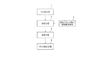
- the method of manufacturing a press-formed product in the present embodiment includes a shearing step 1, a heating step 2, a cooling step 3, and a pressing step 4 in this order. Further, the method of manufacturing a press-formed product in the present embodiment includes stretch flange fracture region estimation processing 5.
- the method for producing a press-formed product of the present embodiment is particularly effective in the case of a steel plate in which the tensile strength of the metal plate is 440 MPa or more.
- a high-tensile material having a pressure of 440 MPa or more is targeted as a metal plate to be pressed.
- a steel plate having a tensile strength of less than 440 MPa, or a metal plate such as an aluminum plate can be applied.
- a single metal plate is formed by trimming the outer peripheral contour shape into a preset shape or forming an opening by shearing a metal plate made of a single plate material formed by rolling or the like. It is a process to obtain.
- a single metal plate means not a collective blank material obtained by welding a plurality of plates but a metal plate made of the same metal material.
- damage to the end face is larger than that of the end face produced by machining, and the end face state becomes uneven, so the stretch flange formability is lowered.
- the stretch flange cracking area estimation process 5 is a process for specifying the position of the stretch flange cracking area, which is an area in which stretch flange cracking is likely to occur when a single metal plate is press-formed in the pressing step 4 It is.
- the specification of such an extension flange crack area may be examined and specified by CAE analysis based on the conditions of press forming in the press working step 4, or may be specified by an actual press. good.
- a curved portion, a burring portion or the like in a plan view is a stretch flange cracking region. Therefore, in a region where extension flange forming is performed, the flange portion having a predetermined curvature radius or more by press processing may be extended in the extension flange cracking region.
- the heating step 2 and the cooling step 3 of the next step are pretreatments before applying pressing including stretch flange forming to a single metal plate after the shearing step 1.
- the heating step 2 is a step of heating at least the metal plate end face of the metal plate end face and the vicinity thereof in the stretch flange crack area specified by the stretch flange crack area estimation processing 5. After it is estimated in the heating step 2 that the temperature of the end surface of the metal plate has reached the target heating temperature, the heating state may be maintained for a certain period of time. If the holding time is long, the production efficiency is reduced, so the holding time is preferably 5 minutes or less. More preferably, the holding time is within 1 minute.
- the heating range X [mm] from the end face position of the metal plate on the surface of a single metal plate is set within the range of equation (1). That is, the area below the heating range X [mm] is the end face and its vicinity. 0 [mm] ⁇ X ⁇ 20 [mm] (1)
- the heating range X [mm] exceeds 20 mm, there is a possibility that the fatigue properties of the parts may be deteriorated with the softening of the material strength (tensile strength), which is not preferable.
- heating range X [mm] is more preferable within 5 mm.
- the heating range X [mm] is preferably in the vicinity of the end face as much as possible, and more preferably within the range of the following formula (2). 0 [mm] ⁇ X ⁇ 8 [mm] (2)
- the heating method is not limited to heating by a laser, and for example, a heating device such as an induction coil may be brought close to the end face side of the metal plate for heating.
- heating by a laser is simple and preferable.
- the heating temperature T [° C.] of the portion to be heated at the time of heating may be a temperature at which softening of the material can occur at the heating position, and is, for example, the annealing temperature of the target metal.
- the heating temperature be, for example, 200 ° C. or more and 1 point or less of Ac of the metal plate.
- the heating rate at the time of heating is preferably rapid heating.
- the heating temperature T [° C.] is at or above the Ac 1 point of the material, the hardness is increased by rapid cooling because it exceeds the transformation point, and conversely, the stretch flange formability may be reduced.
- it is metal, such as a normal steel plate it is thought that a softening process is given by heating 200 degreeC or more.
- the cooling step 3 is a step of cooling at least the metal plate end face of the metal plate end face and the vicinity thereof among the metal plates heated in the heating step 2.
- the cooling process after heating may be either rapid cooling by water cooling or the like, air cooling, or slow cooling. In the case of rapid cooling, stretch flange formability may be reduced when the heating temperature is at or above the Ac 1 point of the material.
- the air cooling may be natural air cooling or air blowing by blowing air from a nozzle. In slow cooling, the cooling rate may be adjusted by adjusting the output at the time of laser heating or induction heating.
- the cooling in the cooling step 3 is performed so that, for example, the end surface of the heated metal plate is lowered by 30 ° C. or more below the target temperature for heating.
- the pressing step 4 is a step of subjecting a metal plate whose end face has been subjected to heating and cooling treatment to press processing including stretch flange forming to obtain a press-formed product having a target shape.
- the press-formed product according to the pressing process 4 may not be the final formed product.
- a blank 10 made of a flat metal plate is simply formed into a press-formed product 11 as shown in FIG. 2 (b) to which a deformation is applied so that the flange is elongated during press forming. I tried pressing.
- stretch flange cracking occurs at a portion indicated by a symbol A in FIG.
- the presence or absence of the occurrence of the elongation flange crack depends on the material strength (tensile strength), the material structure, the sheared end surface state, the surface treatment and the like.
- stretch flange formability also depends on the method of cutting the material end that is subjected to stretch flange deformation.
- a metal plate is cut, for example, by shear processing, damage to the end face produced by machining is greater and the end face state becomes uneven, so stretch flange formability decreases.
- the stretch flange formability changes due to the clearance.
- heat treatment for softening the material is performed with the end face of the metal plate and at least the end face in the vicinity of the end face as a target, and then cooling treatment is performed to fatigue the parts involved in softening the material strength (tensile strength) by heating. It is possible to minimize the deterioration of the characteristics.
- this embodiment is applied to a collective blank including weld end parts obtained by welding two plate members as in the prior art 3, when the area including the weld end part is a stretch flange crack area, the following There is such a problem. That is, in the present embodiment, the heat treatment and the subsequent cooling treatment are performed only on the end face and the vicinity thereof, that is, the end face.
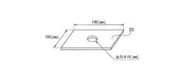
- a 100 mm ⁇ 100 mm square blank material is punched out by using a hole of ⁇ 10 mm with a clearance of 12% at the center of the blank, and the hole spreading test piece (figure The blank 20 in 3) was produced.
- a hole expansion test was carried out with a conical punch 32 as shown in FIG. 3 by imitating press work including stretch flange forming. The wrinkle holding force was set to 8 tons.
- the hole-opening test was carried out under the condition (conventional method) not subjected to the heat treatment as the pretreatment for the hole-opening test and the condition (the present invention) to which the heat treatment was applied.
- heating conditions of heat processing the surface side of blank material 20 was heated using a laser for a heating device, and a heating field was made into an edge field of 1 mm or more and 8 mm or less from a metal plate hole edge.
- heating temperature performed the laser heating surface temperature in the range of 200 to 700 degreeC, respectively.
- air cooling was performed by performing natural air cooling until the temperature of the heated portion heated by the heating device dropped to room temperature. Table 1 summarizes the heating conditions and the results of the hole spreading test.
- no. 1 is the result of the hole expansion test of the sample which has not been heated, and the hole expansion rate was 23%.
- 2 to No. 5 is a result of carrying out laser heating of the range of 1 mm from a hole edge (end face position of a hole), and it is a result of a hole expansion test, and it turned out that a hole expansion rate is improving.
- no. 6 to No. 9 is a range of 3 mm from the hole edge
- No. 10 to No. No. 13 is in the range of 5 mm from the hole edge
- No. 14 to No. 17 is the result of performing a hole expansion test by laser heating each in the range of 8 mm from the hole edge.
- No. 2 to No. Similar to 5 it was found that the hole expansion rate improved as the heating temperature rose.
Abstract
Description
自動車の足回り部品に用いられるプレス成形品の一つとしては、例えばロワアームのように平面視で湾曲した形状の構造部品がある。このような平面視で湾曲した部品形状にプレス成形で加工した場合、湾曲部で伸びフランジ割れが発生するおそれがある。 In recent years, application of high-tensile materials of 590 MPa or more to vehicle body structural components has progressed in order to achieve both improvement in collision safety and weight reduction of automobile bodies. Since high-tensile material has a small hole expansion rate, molding defects such as stretch flange cracking and the like become a problem when performing press forming.
One example of a press-formed product used for an undercarriage part of an automobile is a structural part having a curved shape in plan view, such as a lower arm. When it is processed by press molding into such a component shape curved in a plan view, there is a possibility that stretch flange cracking may occur at the curved portion.
上記のような部品形状や成形工程に対してハイテン材を適用した場合に、特に上記伸びフランジ割れが発生する傾向がある。
伸びフランジ割れに関する従来技術として、例えば特許文献1~特許文献3がある。 In addition, when mass-producing automobile parts by press molding, it is often the case that a pressing process is performed after shear processing such as a trimming process and an piercing process. In this case, stretch flange cracking is likely to occur from the sheared end face edge formed in the trimming process or the piercing process.
When a high-tensile material is applied to the part shape and the forming process as described above, the stretch flange cracking particularly tends to occur.
For example, Patent Documents 1 to 3 disclose prior art related to stretch flange cracking.
特許文献2に記載の方法は、プレス素材としての板状パネルの所定部位に機械的強度を高める強化処理を施し、プレス加工時の成形性を向上させる技術である。特許文献2には、この技術によってプレス加工の進行に伴い応力集中が生じて発生する割れを抑制することができると記載されている。 The method described in Patent Document 1 is a technique for preventing stretch flange cracking that occurs when press forming a high strength steel plate. According to Patent Document 1, when the steel plate is stretch-flanged by this technique, the temperature of the steel plate during forming is heated to 400 ° C. or more and 1000 ° C. or less, so that dynamic recovery of dislocation occurs during processing. It is stated that deposition is less likely to occur and elongation flange cracking is suppressed.
The method described in
また、特許文献2に記載の方法は、強度を高めて割れを抑制する方法であり、伸びが必要な伸びフランジ割れに適用することは難しい。特に引張強度が高いハイテン材に不向きな方法である。 However, in the method described in Patent Document 1, in order to heat the steel plate during press forming, it is necessary to incorporate a heating device in the mold, resulting in a complicated mold shape. Furthermore, by heating to 400 ° C. or more and 1000 ° C. or less, the mold is likely to be damaged and mass production cost may increase.
Further, the method described in
本実施形態におけるプレス成形品の製造方法は、図1に示すように、せん断工程1、加熱工程2、冷却工程3、及びプレス加工工程4をこの順に備える。また本実施形態におけるプレス成形品の製造方法は、伸びフランジ割れ領域推定処理5を有する。
本実施形態のプレス成形品の製造方法は、金属板の引張強度が440MPa以上の鋼板の場合に特に効果的である。本実施形態では、プレス加工する金属板としては440MPa以上のハイテン材を対象とする。ただし、金属板の引張強度が440MPa未満の鋼板や、アルミニウム板などの金属板であっても適用することができる。 Hereinafter, embodiments according to the present invention will be described with reference to the drawings.
As shown in FIG. 1, the method of manufacturing a press-formed product in the present embodiment includes a shearing step 1, a
The method for producing a press-formed product of the present embodiment is particularly effective in the case of a steel plate in which the tensile strength of the metal plate is 440 MPa or more. In this embodiment, a high-tensile material having a pressure of 440 MPa or more is targeted as a metal plate to be pressed. However, even a steel plate having a tensile strength of less than 440 MPa, or a metal plate such as an aluminum plate can be applied.
せん断工程1は、圧延その他で形成された1枚の板材からなる金属板を、予め設定した形状に外周輪郭形状をトリムしたり、せん断により開口部を形成したりして単一の金属板を得る工程である。
本実施形態で「単一の金属板」とは、複数の板を溶接で接合した集合ブランク材ではなく、同一の金属材料からなる金属板であることを意味する。
ここで、せん断加工で金属板を切断した場合、機械加工で作製した端面よりも端面のダメージが大きく、不均一な端面状態になるため、伸びフランジ成形性が低下する。 <Shearing process 1>
In the shearing step 1, a single metal plate is formed by trimming the outer peripheral contour shape into a preset shape or forming an opening by shearing a metal plate made of a single plate material formed by rolling or the like. It is a process to obtain.
In the present embodiment, "a single metal plate" means not a collective blank material obtained by welding a plurality of plates but a metal plate made of the same metal material.
Here, when the metal plate is cut by shearing, damage to the end face is larger than that of the end face produced by machining, and the end face state becomes uneven, so the stretch flange formability is lowered.
伸びフランジ割れ領域推定処理5は、単一の金属板をプレス加工工程4でのプレス成形した際に伸びフランジ割れが発生しやすいと推定される領域である伸びフランジ割れ領域の位置を特定する処理である。
そのような伸びフランジ割れ領域(伸びフランジ割れ危険部位)の特定は、プレス加工工程4でのプレス成形の条件に基づきCAE解析によって検討して特定しても良いし、実プレスで特定しても良い。通常、平面視における湾曲部やバーリング部等が伸びフランジ割れ領域である。このため、簡易に、伸びフランジ成形が行われる領域において、プレス加工で所定以上の曲率半径となるフランジ部を伸びフランジ割れ領域してもよい。 <Stretch flange crack
The stretch flange cracking
The specification of such an extension flange crack area (extension flange crack critical area) may be examined and specified by CAE analysis based on the conditions of press forming in the press working step 4, or may be specified by an actual press. good. Usually, a curved portion, a burring portion or the like in a plan view is a stretch flange cracking region. Therefore, in a region where extension flange forming is performed, the flange portion having a predetermined curvature radius or more by press processing may be extended in the extension flange cracking region.
加熱工程2及び次工程の冷却工程3は、せん断工程1後の単一の金属板に対して、伸びフランジ成形を含むプレス加工を施す前の前処理である。
加熱工程2では、伸びフランジ割れ領域推定処理5が特定した伸びフランジ割れ領域における、金属板端面及びその近傍のうちの少なくとも金属板端面を加熱する工程である。
加熱工程2において、金属板端面の温度が目標とする加熱温度に到達したと推定した後、その加熱状態を一定時間、保持するようにしても良い。保持時間が長い場合は生産効率の低下に繋がるため、保持時間は5分以内が好ましい。より好ましくは、保持時間は1分以内である。 <
The
The
After it is estimated in the
量産を考慮すると、金属板の端面をレーザーで加熱するのは難しいため、金属板表面側から端面近傍を加熱することが好ましい。 It is sufficient to heat only the end face of the metal plate in the stretch flange cracking region. However, since it is difficult to heat only the end face, it is preferable to heat the area near the end face of the metal plate end face and its vicinity as much as possible by laser or induction heating capable of locally heating. Is preferred.
Considering mass production, it is difficult to heat the end face of the metal plate with a laser, so it is preferable to heat the vicinity of the end face from the metal plate surface side.
0[mm] ≦ X ≦ 20[mm] ・・・(1)
ここで、加熱範囲X[mm]が20mmを越える場合、材料強度(引張強度)の軟化に伴い部品の疲労特性が低下する恐れがあるため、好ましくない。また、さらに端面近傍のみを加熱できる装置であれば、加熱範囲X[mm]は5mm以内がより好ましい。 For example, the heating range X [mm] from the end face position of the metal plate on the surface of a single metal plate is set within the range of equation (1). That is, the area below the heating range X [mm] is the end face and its vicinity.
0 [mm] ≦ X ≦ 20 [mm] (1)
Here, when the heating range X [mm] exceeds 20 mm, there is a possibility that the fatigue properties of the parts may be deteriorated with the softening of the material strength (tensile strength), which is not preferable. Moreover, if it is an apparatus which can heat only the end face vicinity, heating range X [mm] is more preferable within 5 mm.
0[mm] ≦ X ≦ 8[mm] ・・・(2)
加熱方法は、レーザーによる加熱に限定されず、例えば、金属板の端面側に誘導コイル等の加熱装置を近づけて加熱するようにしても良い。ただし、レーザーによる加熱が簡便で好ましい。
加熱する際の被加熱部の加熱温度T[℃]は、加熱位置で材料の軟化が発生可能な温度であれば良く、例えば対象とする金属での焼き鈍し温度とする。 Further, from the viewpoint of suppressing a defect due to heating, the heating range X [mm] is preferably in the vicinity of the end face as much as possible, and more preferably within the range of the following formula (2).
0 [mm] ≦ X ≦ 8 [mm] (2)
The heating method is not limited to heating by a laser, and for example, a heating device such as an induction coil may be brought close to the end face side of the metal plate for heating. However, heating by a laser is simple and preferable.
The heating temperature T [° C.] of the portion to be heated at the time of heating may be a temperature at which softening of the material can occur at the heating position, and is, for example, the annealing temperature of the target metal.
加熱時の加熱速度は急速加熱が好ましい。
ここで、加熱温度T[℃]が材料のAc1点以上の場合、変態点を超えるため、急速冷却すると硬度が増し、逆に伸びフランジ成形性が低減する可能性があるため、好ましくない。また、通常の鋼板などの金属であれば、200℃以上の加熱で軟化処理が施されると考えられる。 It is preferable that the heating temperature (target temperature of heating) be, for example, 200 ° C. or more and 1 point or less of Ac of the metal plate.
The heating rate at the time of heating is preferably rapid heating.
Here, when the heating temperature T [° C.] is at or above the Ac 1 point of the material, the hardness is increased by rapid cooling because it exceeds the transformation point, and conversely, the stretch flange formability may be reduced. Moreover, if it is metal, such as a normal steel plate, it is thought that a softening process is given by heating 200 degreeC or more.
冷却工程3は、加熱工程2で加熱された金属板のうち、金属板端面及びその近傍のうちの少なくとも金属板端面を冷却する工程である。
加熱後の冷却処理は、水冷などによる急速冷却、空冷、徐冷のいずれでも良い。急速冷却の場合、加熱温度が材料のAc1点以上では伸びフランジ成形性が低減する可能性がある。空冷は、自然空冷でもノズルから空気を吹き付けることによる空冷であっても良い。徐冷は、レーザー加熱時や誘導加熱時の出力を調整することで冷却速度を調整しても良い。
冷却工程3による冷却は、例えば加熱された金属板端面が、加熱の目標温度よりも30℃以上温度降下するように冷却する。 <Cooling process 3>
The cooling step 3 is a step of cooling at least the metal plate end face of the metal plate end face and the vicinity thereof among the metal plates heated in the
The cooling process after heating may be either rapid cooling by water cooling or the like, air cooling, or slow cooling. In the case of rapid cooling, stretch flange formability may be reduced when the heating temperature is at or above the Ac 1 point of the material. The air cooling may be natural air cooling or air blowing by blowing air from a nozzle. In slow cooling, the cooling rate may be adjusted by adjusting the output at the time of laser heating or induction heating.
The cooling in the cooling step 3 is performed so that, for example, the end surface of the heated metal plate is lowered by 30 ° C. or more below the target temperature for heating.
プレス加工工程4では、端面に加熱・冷却処理を施した金属板に対し、伸びフランジ成形を含むプレス加工を施して、目的の形状のプレス成形品とする工程である。プレス加工工程4によるプレス成形品は最終成形品でなくても良い。 <Pressing process 4>
The pressing step 4 is a step of subjecting a metal plate whose end face has been subjected to heating and cooling treatment to press processing including stretch flange forming to obtain a press-formed product having a target shape. The press-formed product according to the pressing process 4 may not be the final formed product.
図2(a)に示すように、平板の金属板からなるブランク材10を、単純に、プレス成形時にフランジが伸ばされる変形が付与される図2(b)に示すようなプレス成形品11にプレス加工してみた。このとき、金属板10にハイテン材を適用してプレス成形すると、図2(b)中、符号Aで示す部位で、伸びフランジ割れが発生した。この伸びフランジ割れの発生の有無は、材料強度(引張強度)、材料組織、せん断端面状態、表面処理等に依存する。 <About other effects>
As shown in FIG. 2 (a), a blank 10 made of a flat metal plate is simply formed into a press-formed
また伸びフランジ成形性は、伸びフランジ変形を受ける材料端部の切断方法に依存する。金属板を、例えばせん断加工で切断した場合、機械加工で作製した端面よりもダメージが大きく、不均一な端面状態になるため、伸びフランジ成形性が低下する。さらに、せん断加工の場合でもクリアランスにより伸びフランジ成形性が変化する。 For example, in the case of the material of the composite structure found in the super high strength material, the difference in hardness of the structure reduces stretch flange formability as compared with the material of single phase structure.
Stretch flange formability also depends on the method of cutting the material end that is subjected to stretch flange deformation. When a metal plate is cut, for example, by shear processing, damage to the end face produced by machining is greater and the end face state becomes uneven, so stretch flange formability decreases. Furthermore, even in the case of shear processing, the stretch flange formability changes due to the clearance.
この結果、本実施形態では、前処理としての加熱・冷却によって、伸びフランジ割れ危険部の材料の組織変化、すなわち材料の軟化やひずみ除去が行われることで、伸びフランジ成形性が向上する。 In the method of manufacturing a press-formed product according to the present embodiment, in order to reduce stretch flange cracking that occurs due to materials and processing conditions that are disadvantageous to such stretch flange forming, in the stretch flange fracture risk region, cracking is caused by shearing. After the end face of the metal plate which has become a starting point is heated and cooled, press forming is performed.
As a result, in the present embodiment, the stretch flange formability is improved by the structural change of the material of the stretch flange fracture danger portion, that is, the softening and strain removal of the material by heating and cooling as the pretreatment.
なお、先行文献3のような2つの板材を溶接した溶接端部を含む集合ブランク材に、本実施形態を適用したとき、溶接端部を含む領域が伸びフランジ割れ領域の場合には、次のような問題がある。すなわち、本実施形態では端面及びその近傍だけ、つまり端面を中心に加熱処理とその後の冷却処理が施されることになる。したがって、本実施形態を適用すると、相対的に引張強度が弱い溶接端部の端面でプレス成形時に割れが発生する可能性がある。このため、伸びフランジ割れ領域に溶接端部が存在するような金属板を対象としたプレス成形品の製造は、本実施形態の対象外である。 In particular, heat treatment for softening the material is performed with the end face of the metal plate and at least the end face in the vicinity of the end face as a target, and then cooling treatment is performed to fatigue the parts involved in softening the material strength (tensile strength) by heating. It is possible to minimize the deterioration of the characteristics.
When this embodiment is applied to a collective blank including weld end parts obtained by welding two plate members as in the prior art 3, when the area including the weld end part is a stretch flange crack area, the following There is such a problem. That is, in the present embodiment, the heat treatment and the subsequent cooling treatment are performed only on the end face and the vicinity thereof, that is, the end face. Therefore, when this embodiment is applied, a crack may occur at the time of press forming at the end face of the welding end portion having a relatively low tensile strength. For this reason, the production of a press-formed product intended for a metal plate in which the welded end portion exists in the stretch flange fracture region is out of the scope of the present embodiment.
本実施例では図3に示す穴広げ試験により伸びフランジ成形性を評価した。図3中、符号20がブランク材を、符号30がダイを、符号31がブランクホルダーを、符号32がパンチをそれぞれ示す。 In order to confirm the improvement effect of the stretch flange formability by the press forming method according to the present invention, the hole expansion test was performed after partially heating and air cooling the test piece of the hole expansion test. The results are described below.
In this example, stretch flange formability was evaluated by the hole spreading test shown in FIG. In FIG. 3,
作製した穴広げ試験片に対し、伸びフランジ成形を含むプレス加工を模して、図3のように、円錐型のパンチ32により穴広げ試験を実施した。しわ押さえ力は8tonに設定した。 First, as shown in FIG. 4, a 100 mm × 100 mm square blank material is punched out by using a hole of φ 10 mm with a clearance of 12% at the center of the blank, and the hole spreading test piece (figure The blank 20 in 3) was produced. The metal plate which comprises the blank material used by the present Example was taken as plate thickness t = 1.2mm, and tensile strength 1180MPa grade steel plate.
With respect to the prepared hole expansion test piece, a hole expansion test was carried out with a
加熱処理の加熱条件としては、加熱装置にレーザーを使用してブランク材20の表面側を加熱し、加熱領域は金属板穴縁から1mm以上8mm以下の端縁領域とした。また加熱温度は、レーザー加熱面温度を200℃以上700℃以下の範囲でそれぞれ行った。
また、空冷(冷却)は、加熱装置で加熱した加熱部分が常温に温度降下するまで自然空冷を行うことで実施した。
表1に加熱条件及び穴広げ試験結果をまとめて示す。 At this time, the hole-opening test was carried out under the condition (conventional method) not subjected to the heat treatment as the pretreatment for the hole-opening test and the condition (the present invention) to which the heat treatment was applied.
As heating conditions of heat processing, the surface side of
In addition, air cooling (cooling) was performed by performing natural air cooling until the temperature of the heated portion heated by the heating device dropped to room temperature.
Table 1 summarizes the heating conditions and the results of the hole spreading test.

また、No.6~No.9は穴縁から3mmの範囲、No.10~No.13は穴縁から5mmの範囲、No.14~No.17は穴縁から8mmの範囲、をそれぞれレーザー加熱し、穴広げ試験を行った結果である。この場合においても、No.2~No.5と同様に、加熱温度の上昇に伴い穴広げ率が向上することが分かった。 As can be seen from Table 1, no. 1 is the result of the hole expansion test of the sample which has not been heated, and the hole expansion rate was 23%. With respect to this result, according to No. 1 based on the present invention. 2 to No. 5 is a result of carrying out laser heating of the range of 1 mm from a hole edge (end face position of a hole), and it is a result of a hole expansion test, and it turned out that a hole expansion rate is improving.
Also, no. 6 to No. 9 is a range of 3 mm from the hole edge, No. 10 to No. No. 13 is in the range of 5 mm from the hole edge, No. 14 to No. 17 is the result of performing a hole expansion test by laser heating each in the range of 8 mm from the hole edge. Also in this case, No. 2 to No. Similar to 5, it was found that the hole expansion rate improved as the heating temperature rose.
2 加熱工程
3 冷却工程
4 プレス加工工程
5 伸びフランジ割れ領域推定処理
10 金属板(ブランク材)
11 プレス成形品
20 ブランク材 1
11 Press-formed
Claims (4)
- 1枚の板材からなる金属板をせん断加工した後の単一の金属板に対し、伸びフランジ成形を含むプレス加工を施して製造するプレス成形品の製造方法において、
上記単一の金属板を上記プレス加工でプレス成形した際に伸びフランジ割れが発生しやすいと推定される領域を伸びフランジ割れ領域とした場合に、
上記せん断加工後の単一の金属板における、上記伸びフランジ割れ領域内に位置する金属板端面及びその近傍のうちの少なくとも金属板端面を加熱し冷却してから、上記プレス加工を施すことを特徴とするプレス成形品の製造方法。 In a method of producing a press-formed product produced by subjecting a single metal plate after shearing a metal plate made of a single plate material to press working including stretch flange forming,
In a case where an area in which stretch flange cracking is likely to occur when the single metal sheet is press-formed by the above-described pressing is used as a stretch flange cracking area,
The above-mentioned press working is performed after heating and cooling at least the metal plate end face of the metal plate end face located in the stretch flange cracking region and the vicinity thereof in the single metal plate after the shear processing A method of manufacturing a press-formed product. - 上記加熱する際の被加熱部の加熱温度T[℃]を、200℃以上、且つ上記金属板のAc1点以下とすることを特徴とする請求項1記載のプレス成形品の製造方法。 The method for producing a press-formed product according to claim 1, wherein the heating temperature T [° C] of the heated portion at the time of the heating is 200 ° C or more and one Ac point or less of the metal plate.
- 上記単一の金属板表面における、上記加熱する際における金属板の端面位置からの加熱範囲X[mm]を、(1)式の範囲内とすることを特徴とする請求項1又は請求項2に記載のプレス成形品の製造方法。
0[mm] ≦ X ≦ 20[mm] ・・・(1) The heating range X [mm] from the end face position of the metal plate at the time of the heating on the surface of the single metal plate is set within the range of the formula (1). The manufacturing method of the press-formed article as described in-.
0 [mm] ≦ X ≦ 20 [mm] (1) - 上記金属板は、引張強度が440MPa以上の鋼板とすることを特徴とする請求項1~請求項3のいずれか1項に記載のプレス成形品の製造方法。 The method of manufacturing a press-formed product according to any one of claims 1 to 3, wherein the metal plate is a steel plate having a tensile strength of 440 MPa or more.
Priority Applications (6)
| Application Number | Priority Date | Filing Date | Title |
|---|---|---|---|
| US16/957,122 US11511330B2 (en) | 2017-12-25 | 2018-12-17 | Method for manufacturing press formed product |
| KR1020207017270A KR102340442B1 (en) | 2017-12-25 | 2018-12-17 | Manufacturing method of press-formed products |
| CN201880083421.1A CN111565863A (en) | 2017-12-25 | 2018-12-17 | Method for producing press-molded article |
| JP2019538273A JP6624353B2 (en) | 2017-12-25 | 2018-12-17 | Manufacturing method of press-formed product |
| MX2020006701A MX2020006701A (en) | 2017-12-25 | 2018-12-17 | Method for manufacturing press formed product. |
| EP18897134.5A EP3733320A4 (en) | 2017-12-25 | 2018-12-17 | Method for manufacturing press formed product |
Applications Claiming Priority (2)
| Application Number | Priority Date | Filing Date | Title |
|---|---|---|---|
| JP2017-247992 | 2017-12-25 | ||
| JP2017247992 | 2017-12-25 |
Publications (1)
| Publication Number | Publication Date |
|---|---|
| WO2019131289A1 true WO2019131289A1 (en) | 2019-07-04 |
Family
ID=67067161
Family Applications (1)
| Application Number | Title | Priority Date | Filing Date |
|---|---|---|---|
| PCT/JP2018/046409 WO2019131289A1 (en) | 2017-12-25 | 2018-12-17 | Method for manufacturing press formed product |
Country Status (7)
| Country | Link |
|---|---|
| US (1) | US11511330B2 (en) |
| EP (1) | EP3733320A4 (en) |
| JP (1) | JP6624353B2 (en) |
| KR (1) | KR102340442B1 (en) |
| CN (1) | CN111565863A (en) |
| MX (1) | MX2020006701A (en) |
| WO (1) | WO2019131289A1 (en) |
Cited By (3)
| Publication number | Priority date | Publication date | Assignee | Title |
|---|---|---|---|---|
| WO2020175486A1 (en) * | 2019-02-27 | 2020-09-03 | Jfeスチール株式会社 | Method for manufacturing steel sheet for cold press and method for manufacturing press component |
| JP2021139012A (en) * | 2020-03-06 | 2021-09-16 | Jfeスチール株式会社 | Production method of steel sheet for press, manufacturing method of pressed component, steel sheet, and evaluation method for formability of stretch flange |
| US11511330B2 (en) | 2017-12-25 | 2022-11-29 | Jfe Steel Corporation | Method for manufacturing press formed product |
Families Citing this family (2)
| Publication number | Priority date | Publication date | Assignee | Title |
|---|---|---|---|---|
| KR20210155437A (en) * | 2020-06-15 | 2021-12-23 | 삼성디스플레이 주식회사 | Window molding apparatus and window molding method using the same |
| KR102402484B1 (en) | 2021-12-27 | 2022-05-26 | 김은조 | Press-Formed Product Manufacturing Method |
Citations (4)
| Publication number | Priority date | Publication date | Assignee | Title |
|---|---|---|---|---|
| JPH08117879A (en) | 1994-08-29 | 1996-05-14 | Toyota Motor Corp | Pressing method |
| JP2783490B2 (en) | 1993-02-02 | 1998-08-06 | 本田技研工業株式会社 | Manufacturing method of collective blank members |
| JP2001323318A (en) * | 2000-05-15 | 2001-11-22 | High Frequency Heattreat Co Ltd | Method for forming sheet |
| JP2002113527A (en) | 2000-10-05 | 2002-04-16 | Nippon Steel Corp | Manufacturing method for steel plate press formed body and steel plate press formed body formed by the manufacturing method |
Family Cites Families (17)
| Publication number | Priority date | Publication date | Assignee | Title |
|---|---|---|---|---|
| US4122700A (en) * | 1976-09-02 | 1978-10-31 | Armco Steel Corporation | Process for forming sheet metal stock |
| JP2004124151A (en) * | 2002-10-01 | 2004-04-22 | Japan Science & Technology Corp | Heat treatment method for aluminum alloy |
| DE102007008117B8 (en) * | 2007-02-19 | 2009-04-23 | Voestalpine Anarbeitung Gmbh | Method and device for tempered forming of hot-rolled steel material |
| JP2010227954A (en) * | 2009-03-26 | 2010-10-14 | Furukawa-Sky Aluminum Corp | Method of press-forming aluminum alloy sheet |
| DE102009014670B4 (en) * | 2009-03-27 | 2011-01-13 | Thyssenkrupp Sofedit S.A.S | Method and hot forming plant for the production of press-hardened shaped components from sheet steel |
| JP5825119B2 (en) * | 2011-04-25 | 2015-12-02 | Jfeスチール株式会社 | High-strength steel sheet with excellent workability and material stability and method for producing the same |
| ES2577077T3 (en) * | 2011-07-21 | 2016-07-12 | Kabushiki Kaisha Kobe Seiko Sho | Method for producing a hot pressure molded steel element |
| KR101596615B1 (en) | 2012-05-17 | 2016-02-22 | 신닛테츠스미킨 카부시키카이샤 | Plastic working method and plastic working device for metal material |
| JP6655863B2 (en) * | 2013-07-12 | 2020-03-04 | キヤノンファインテックニスカ株式会社 | Sheet bundle binding device and image forming system having the same |
| EP3023168B1 (en) * | 2013-07-19 | 2021-03-03 | JFE Steel Corporation | Press forming method |
| DE102014016614A1 (en) * | 2014-10-31 | 2016-05-04 | Salzgitter Flachstahl Gmbh | Process for producing a component by forming a steel circuit board |
| KR102028068B1 (en) * | 2014-12-25 | 2019-10-02 | 닛폰세이테츠 가부시키가이샤 | Manufacturing Method of Panel Shaped Product |
| US20190119768A1 (en) * | 2016-05-04 | 2019-04-25 | Magna International Inc. | Hot forming tool with infrared light source |
| CN106064193B (en) * | 2016-07-01 | 2018-10-26 | 华侨大学 | A kind of blanking method of ultra-high strength steel plate |
| DE102016121905A1 (en) * | 2016-11-15 | 2018-05-17 | Salzgitter Flachstahl Gmbh | Method for producing dual-phase steel wheel discs with improved cold workability |
| JP6958214B2 (en) * | 2017-10-16 | 2021-11-02 | 日本製鉄株式会社 | Manufacturing method of processed steel parts |
| JP6624353B2 (en) | 2017-12-25 | 2019-12-25 | Jfeスチール株式会社 | Manufacturing method of press-formed product |
-
2018
- 2018-12-17 JP JP2019538273A patent/JP6624353B2/en active Active
- 2018-12-17 MX MX2020006701A patent/MX2020006701A/en unknown
- 2018-12-17 CN CN201880083421.1A patent/CN111565863A/en active Pending
- 2018-12-17 WO PCT/JP2018/046409 patent/WO2019131289A1/en unknown
- 2018-12-17 US US16/957,122 patent/US11511330B2/en active Active
- 2018-12-17 EP EP18897134.5A patent/EP3733320A4/en active Pending
- 2018-12-17 KR KR1020207017270A patent/KR102340442B1/en active IP Right Grant
Patent Citations (4)
| Publication number | Priority date | Publication date | Assignee | Title |
|---|---|---|---|---|
| JP2783490B2 (en) | 1993-02-02 | 1998-08-06 | 本田技研工業株式会社 | Manufacturing method of collective blank members |
| JPH08117879A (en) | 1994-08-29 | 1996-05-14 | Toyota Motor Corp | Pressing method |
| JP2001323318A (en) * | 2000-05-15 | 2001-11-22 | High Frequency Heattreat Co Ltd | Method for forming sheet |
| JP2002113527A (en) | 2000-10-05 | 2002-04-16 | Nippon Steel Corp | Manufacturing method for steel plate press formed body and steel plate press formed body formed by the manufacturing method |
Non-Patent Citations (1)
| Title |
|---|
| See also references of EP3733320A4 |
Cited By (4)
| Publication number | Priority date | Publication date | Assignee | Title |
|---|---|---|---|---|
| US11511330B2 (en) | 2017-12-25 | 2022-11-29 | Jfe Steel Corporation | Method for manufacturing press formed product |
| WO2020175486A1 (en) * | 2019-02-27 | 2020-09-03 | Jfeスチール株式会社 | Method for manufacturing steel sheet for cold press and method for manufacturing press component |
| JP2021139012A (en) * | 2020-03-06 | 2021-09-16 | Jfeスチール株式会社 | Production method of steel sheet for press, manufacturing method of pressed component, steel sheet, and evaluation method for formability of stretch flange |
| JP7264090B2 (en) | 2020-03-06 | 2023-04-25 | Jfeスチール株式会社 | METHOD FOR MANUFACTURING STEEL PLATE FOR PRESSING, METHOD FOR MANUFACTURING PRESSED PARTS, AND METHOD FOR EVALUATING STRETCH FLANGING FORMABILITY |
Also Published As
| Publication number | Publication date |
|---|---|
| JP6624353B2 (en) | 2019-12-25 |
| KR102340442B1 (en) | 2021-12-16 |
| JPWO2019131289A1 (en) | 2019-12-26 |
| EP3733320A1 (en) | 2020-11-04 |
| US11511330B2 (en) | 2022-11-29 |
| MX2020006701A (en) | 2020-08-20 |
| CN111565863A (en) | 2020-08-21 |
| KR20200087229A (en) | 2020-07-20 |
| US20200346269A1 (en) | 2020-11-05 |
| EP3733320A4 (en) | 2021-03-10 |
Similar Documents
| Publication | Publication Date | Title |
|---|---|---|
| WO2019131289A1 (en) | Method for manufacturing press formed product | |
| JP2018130761A (en) | Hot-stamping method | |
| US20090155615A1 (en) | Designed orientation for welded automotive structural components made of press hardened steel | |
| US20190291160A1 (en) | Method for machining a sheet-metal profile | |
| KR20170077192A (en) | Method for producing a component by subjecting a sheet bar of steel to a forming process | |
| WO2016136909A1 (en) | Shearing method | |
| JPWO2016143820A1 (en) | Burring method | |
| US9127330B2 (en) | Method of shaping and hardening a sheet steel blank | |
| JP4959605B2 (en) | Press molding method and base plate for press molding | |
| JP2019111567A (en) | Manufacturing method of press forming article | |
| RU2743046C1 (en) | Method for producing a component as a result of additional forming of a pre-formed circuit | |
| JPWO2020145063A1 (en) | Shearing method of metal plate and manufacturing method of pressed parts | |
| WO2021200233A1 (en) | Method for manufacturing pressed component, method for manufacturing blank material, and steel sheet | |
| JP7276428B2 (en) | Method for manufacturing steel plate for cold press and method for manufacturing pressed part | |
| KR101738985B1 (en) | Hot formed steel part for vehicles and the method for manufacturing the same | |
| US20220341015A1 (en) | Aluminum forming method | |
| US11938577B2 (en) | Method and device for cutting a workpiece | |
| WO2023037961A1 (en) | Method for improving delayed fracture characteristics of steel sheet, method for producing blank, method for producing press-formed article, and press-formed article | |
| CN113597475B (en) | Steel sheet and member | |
| JP2023055526A (en) | Press-formed product manufacturing method |
Legal Events
| Date | Code | Title | Description |
|---|---|---|---|
| ENP | Entry into the national phase |
Ref document number: 2019538273 Country of ref document: JP Kind code of ref document: A |
|
| 121 | Ep: the epo has been informed by wipo that ep was designated in this application |
Ref document number: 18897134 Country of ref document: EP Kind code of ref document: A1 |
|
| ENP | Entry into the national phase |
Ref document number: 20207017270 Country of ref document: KR Kind code of ref document: A |
|
| NENP | Non-entry into the national phase |
Ref country code: DE |
|
| ENP | Entry into the national phase |
Ref document number: 2018897134 Country of ref document: EP Effective date: 20200727 |