JP6624353B2 - Manufacturing method of press-formed product - Google Patents
Manufacturing method of press-formed product Download PDFInfo
- Publication number
- JP6624353B2 JP6624353B2 JP2019538273A JP2019538273A JP6624353B2 JP 6624353 B2 JP6624353 B2 JP 6624353B2 JP 2019538273 A JP2019538273 A JP 2019538273A JP 2019538273 A JP2019538273 A JP 2019538273A JP 6624353 B2 JP6624353 B2 JP 6624353B2
- Authority
- JP
- Japan
- Prior art keywords
- press
- metal plate
- stretch flange
- heating
- formed product
- Prior art date
- Legal status (The legal status is an assumption and is not a legal conclusion. Google has not performed a legal analysis and makes no representation as to the accuracy of the status listed.)
- Active
Links
- 238000004519 manufacturing process Methods 0.000 title claims description 22
- 238000010438 heat treatment Methods 0.000 claims description 71
- 229910052751 metal Inorganic materials 0.000 claims description 55
- 239000002184 metal Substances 0.000 claims description 55
- 238000000034 method Methods 0.000 claims description 45
- 239000000463 material Substances 0.000 claims description 42
- 230000008569 process Effects 0.000 claims description 20
- 238000010008 shearing Methods 0.000 claims description 16
- 229910000831 Steel Inorganic materials 0.000 claims description 8
- 239000010959 steel Substances 0.000 claims description 8
- 230000002093 peripheral effect Effects 0.000 claims description 4
- 238000004458 analytical method Methods 0.000 claims description 2
- 238000001816 cooling Methods 0.000 description 28
- 238000012360 testing method Methods 0.000 description 15
- 238000005336 cracking Methods 0.000 description 11
- 238000000465 moulding Methods 0.000 description 8
- 238000012545 processing Methods 0.000 description 7
- 238000011282 treatment Methods 0.000 description 6
- 238000004093 laser heating Methods 0.000 description 4
- 238000003466 welding Methods 0.000 description 4
- 230000006698 induction Effects 0.000 description 3
- 238000003825 pressing Methods 0.000 description 3
- 238000007796 conventional method Methods 0.000 description 2
- 230000007547 defect Effects 0.000 description 2
- 230000006866 deterioration Effects 0.000 description 2
- 230000000694 effects Effects 0.000 description 2
- 230000006872 improvement Effects 0.000 description 2
- 238000003754 machining Methods 0.000 description 2
- 238000010583 slow cooling Methods 0.000 description 2
- 238000009966 trimming Methods 0.000 description 2
- 230000009471 action Effects 0.000 description 1
- 229910052782 aluminium Inorganic materials 0.000 description 1
- XAGFODPZIPBFFR-UHFFFAOYSA-N aluminium Chemical compound [Al] XAGFODPZIPBFFR-UHFFFAOYSA-N 0.000 description 1
- 238000000137 annealing Methods 0.000 description 1
- FFBHFFJDDLITSX-UHFFFAOYSA-N benzyl N-[2-hydroxy-4-(3-oxomorpholin-4-yl)phenyl]carbamate Chemical compound OC1=C(NC(=O)OCC2=CC=CC=C2)C=CC(=C1)N1CCOCC1=O FFBHFFJDDLITSX-UHFFFAOYSA-N 0.000 description 1
- 238000007664 blowing Methods 0.000 description 1
- 230000008859 change Effects 0.000 description 1
- 239000002131 composite material Substances 0.000 description 1
- 238000005520 cutting process Methods 0.000 description 1
- 230000008021 deposition Effects 0.000 description 1
- 238000005516 engineering process Methods 0.000 description 1
- 230000001678 irradiating effect Effects 0.000 description 1
- 230000014759 maintenance of location Effects 0.000 description 1
- 239000007769 metal material Substances 0.000 description 1
- 238000012986 modification Methods 0.000 description 1
- 230000004048 modification Effects 0.000 description 1
- 238000002203 pretreatment Methods 0.000 description 1
- 238000011084 recovery Methods 0.000 description 1
- 230000009467 reduction Effects 0.000 description 1
- 238000005096 rolling process Methods 0.000 description 1
- 239000002436 steel type Substances 0.000 description 1
- 238000005728 strengthening Methods 0.000 description 1
- 238000004381 surface treatment Methods 0.000 description 1
- 230000009466 transformation Effects 0.000 description 1
- XLYOFNOQVPJJNP-UHFFFAOYSA-N water Substances O XLYOFNOQVPJJNP-UHFFFAOYSA-N 0.000 description 1
- 230000037303 wrinkles Effects 0.000 description 1
Images


Classifications
-
- C—CHEMISTRY; METALLURGY
- C21—METALLURGY OF IRON
- C21D—MODIFYING THE PHYSICAL STRUCTURE OF FERROUS METALS; GENERAL DEVICES FOR HEAT TREATMENT OF FERROUS OR NON-FERROUS METALS OR ALLOYS; MAKING METAL MALLEABLE, e.g. BY DECARBURISATION OR TEMPERING
- C21D1/00—General methods or devices for heat treatment, e.g. annealing, hardening, quenching or tempering
- C21D1/26—Methods of annealing
- C21D1/30—Stress-relieving
-
- B—PERFORMING OPERATIONS; TRANSPORTING
- B21—MECHANICAL METAL-WORKING WITHOUT ESSENTIALLY REMOVING MATERIAL; PUNCHING METAL
- B21D—WORKING OR PROCESSING OF SHEET METAL OR METAL TUBES, RODS OR PROFILES WITHOUT ESSENTIALLY REMOVING MATERIAL; PUNCHING METAL
- B21D19/00—Flanging or other edge treatment, e.g. of tubes
-
- B—PERFORMING OPERATIONS; TRANSPORTING
- B21—MECHANICAL METAL-WORKING WITHOUT ESSENTIALLY REMOVING MATERIAL; PUNCHING METAL
- B21D—WORKING OR PROCESSING OF SHEET METAL OR METAL TUBES, RODS OR PROFILES WITHOUT ESSENTIALLY REMOVING MATERIAL; PUNCHING METAL
- B21D22/00—Shaping without cutting, by stamping, spinning, or deep-drawing
- B21D22/20—Deep-drawing
- B21D22/26—Deep-drawing for making peculiarly, e.g. irregularly, shaped articles
-
- B—PERFORMING OPERATIONS; TRANSPORTING
- B21—MECHANICAL METAL-WORKING WITHOUT ESSENTIALLY REMOVING MATERIAL; PUNCHING METAL
- B21D—WORKING OR PROCESSING OF SHEET METAL OR METAL TUBES, RODS OR PROFILES WITHOUT ESSENTIALLY REMOVING MATERIAL; PUNCHING METAL
- B21D37/00—Tools as parts of machines covered by this subclass
- B21D37/16—Heating or cooling
-
- C—CHEMISTRY; METALLURGY
- C21—METALLURGY OF IRON
- C21D—MODIFYING THE PHYSICAL STRUCTURE OF FERROUS METALS; GENERAL DEVICES FOR HEAT TREATMENT OF FERROUS OR NON-FERROUS METALS OR ALLOYS; MAKING METAL MALLEABLE, e.g. BY DECARBURISATION OR TEMPERING
- C21D9/00—Heat treatment, e.g. annealing, hardening, quenching or tempering, adapted for particular articles; Furnaces therefor
- C21D9/46—Heat treatment, e.g. annealing, hardening, quenching or tempering, adapted for particular articles; Furnaces therefor for sheet metals
Description
本発明は、金属板をプレス成形した際における伸びフランジ割れの危険を低減してからプレス加工を施して製造する、プレス成形品の製造方法に関する。本発明は、特に、自動車用の車体構造部品の製造に好適な技術である。 The present invention relates to a method for manufacturing a press-formed product, which is manufactured by performing press working after reducing the risk of stretch flange cracking when a metal plate is press-formed. The present invention is a technique particularly suitable for manufacturing a vehicle body structural part for an automobile.
近年、自動車車体の衝突安全性向上と軽量化を両立させるために、車体構造部品に対し590MPa以上のハイテン材の適用が進んでいる。ハイテン材は、穴広げ率が小さいため、プレス成形を行う上で伸びフランジ割れなどの成形不良が課題となる。
自動車の足回り部品に用いられるプレス成形品の一つとしては、例えばロワアームのように平面視で湾曲した形状の構造部品がある。このような平面視で湾曲した部品形状にプレス成形で加工した場合、湾曲部で伸びフランジ割れが発生するおそれがある。In recent years, in order to achieve both improvement in collision safety and reduction in weight of an automobile body, application of a high-tensile material of 590 MPa or more to body structural parts has been advanced. Since the high-tensile material has a small hole expansion ratio, there is a problem of poor forming such as a stretch flange crack in press forming.
As one of press-formed products used for underbody parts of automobiles, for example, there is a structural part having a curved shape in plan view such as a lower arm. In the case where such a part curved in a plan view is processed by press molding, there is a possibility that a stretch flange crack may occur at a curved portion.
また、自動車部品をプレス成形で量産する場合、トリム工程やピアス工程などのせん断加工をしてからプレス加工工程に入る場合も多い。この場合、トリム工程やピアス工程で形成されたせん断端面縁から伸びフランジ割れが発生しやすい。
上記のような部品形状や成形工程に対してハイテン材を適用した場合に、特に上記伸びフランジ割れが発生する傾向がある。
伸びフランジ割れに関する従来技術として、例えば特許文献1〜特許文献3がある。In addition, when mass-producing automobile parts by press molding, there are many cases where a shearing process such as a trim process or a piercing process is performed before the press process is started. In this case, the flange is likely to extend from the edge of the sheared end face formed in the trimming step or the piercing step.
When the high-tensile material is applied to the component shape and the molding process as described above, the stretch flange cracks particularly tend to occur.
For example, Patent Literatures 1 to 3 disclose conventional techniques relating to stretch flange cracking.
特許文献1に記載の方法は、高強度鋼板をプレス成形する際に発生する伸びフランジ割れを防止する技術である。特許文献1には、この技術によって鋼板を伸びフランジ成形する際に、成形中の鋼板温度を400℃以上1000℃以下まで加熱することで、加工中に転位の動的回復が起きて、転位の堆積が起こりにくくなり、伸びフランジ割れが抑制されると記載されている。
特許文献2に記載の方法は、プレス素材としての板状パネルの所定部位に機械的強度を高める強化処理を施し、プレス加工時の成形性を向上させる技術である。特許文献2には、この技術によってプレス加工の進行に伴い応力集中が生じて発生する割れを抑制することができると記載されている。The method described in Patent Document 1 is a technique for preventing stretch flange cracking that occurs when press-forming a high-strength steel sheet. Patent Document 1 discloses that when a steel sheet is stretch-flange-formed by this technique, the temperature of the steel sheet during forming is heated to 400 ° C. or more and 1000 ° C. or less, so that dynamic recovery of dislocation occurs during processing, and It is described that deposition is less likely to occur and stretch flange cracking is suppressed.
The method described in
特許文献3に記載の方法は、複数の板材の端部を突き合わせた状態で、その突合せ縁にレーザー光を照射して端部同士を溶接して作製された集合ブランク材を、プレス成形するための技術である。そして、特許文献3では、板材同士の溶接端部位置及びその近傍が、プレス成形によって平面視で湾曲形状にプレス加工される場合には、プレス加工前に、溶接端部を含む板材周縁部及びその近傍にレーザー光を照射して焼鈍し軟化処理を施すことが記載されている。この処理によって、板材周縁部に応力集中が発生することが阻止され、プレス成形時に軟化部位が容易に伸びて、溶接端部への応力集中が防止されると記載されている。
The method described in
しかしながら、特許文献1に記載の方法では、プレス成形中の鋼板を加熱するため、金型内に加熱装置を組み込む必要があり、複雑な金型形状になる。さらに、400℃以上1000℃以下まで加熱することにより金型が傷みやすくなり、量産コストが増加する可能性がある。
また、特許文献2に記載の方法は、強度を高めて割れを抑制する方法であり、伸びが必要な伸びフランジ割れに適用することは難しい。特に引張強度が高いハイテン材に不向きな方法である。However, in the method described in Patent Literature 1, a heating device needs to be incorporated in a mold to heat a steel sheet during press forming, resulting in a complicated mold shape. Furthermore, heating to 400 ° C. or more and 1000 ° C. or less may cause the mold to be easily damaged, which may increase the mass production cost.
Further, the method described in
また特許文献3に記載の方法は、伸びフランジ割れ危険領域のひずみを分散させて溶接部近傍の伸びフランジ割れを抑制する方法である。しかし、特許文献3に記載の方法は、材料ごとの加熱温度や加熱領域、鋼種の条件の記載がなく、局所的な伸びフランジ成形では十分な伸びフランジ成形性を得られない可能性がある。また特許文献3に記載の方法では、溶接端部の割れを防止するための軟化処理であることから加熱処理を施す領域が比較的広範囲になるおそれがある。
The method described in
本発明は、上記のような点を鑑みてなされたもので、金型形状を複雑にすることなく、必要以上に加熱処理を施すこともなく、伸びフランジ割れを抑制することができて、成形不良を抑制したプレス成形品を提供することを目的とする。 The present invention has been made in view of the above points, and without complicating the mold shape, without performing unnecessary heat treatment, can suppress stretch flange cracking, An object of the present invention is to provide a press-formed product in which defects are suppressed.
課題を解決するために、本発明の一態様であるプレス成形品の製造方法は、1枚の板材からなる金属板をせん断加工した後の単一の金属板に対し、伸びフランジ成形を含むプレス加工を施して製造するプレス成形品の製造方法において、上記単一の金属板を上記プレス加工でプレス成形した際に伸びフランジ割れが発生しやすいと推定される領域を伸びフランジ割れ領域とした場合に、上記せん断加工後の単一の金属板における、上記伸びフランジ割れ領域内に位置する金属板端面及びその近傍のうちの少なくとも金属板端面を加熱し冷却してから、上記プレス加工を施すことを特徴とする。 In order to solve the problem, a method of manufacturing a press-formed product according to one embodiment of the present invention is directed to a press including stretch flange forming for a single metal plate obtained by shearing a metal plate made of one sheet material. In the method of manufacturing a press-formed product manufactured by performing processing, a region where it is estimated that stretch flange cracking is likely to occur when the single metal plate is press-formed by the press working is defined as a stretch flange crack region. After heating and cooling at least the metal plate end surface located in the stretch flange crack region and its vicinity in the single metal plate after the above-mentioned shearing, and then performing the press working It is characterized by.
本発明の一態様によれば、必要以上の領域に加熱を施すことなく、伸びフランジ割れが発生する部品の割れ危険を大きく低減することができて、成形不良を抑制したプレス成形品を提供することができる。この結果、成形性の良い部品が得られ、歩留まりの向上に繋がる。 According to one aspect of the present invention, there is provided a press-formed product that can significantly reduce the risk of cracking of a component in which stretch flange cracking occurs without heating a region more than necessary, and suppresses molding defects. be able to. As a result, a part having good moldability is obtained, which leads to an improvement in yield.
以下、本発明に係る実施形態について図面を参照しつつ説明する。
本実施形態におけるプレス成形品の製造方法は、図1に示すように、せん断工程1、加熱工程2、冷却工程3、及びプレス加工工程4をこの順に備える。また本実施形態におけるプレス成形品の製造方法は、伸びフランジ割れ領域推定処理5を有する。
本実施形態のプレス成形品の製造方法は、金属板の引張強度が440MPa以上の鋼板の場合に特に効果的である。本実施形態では、プレス加工する金属板としては440MPa以上のハイテン材を対象とする。ただし、金属板の引張強度が440MPa未満の鋼板や、アルミニウム板などの金属板であっても適用することができる。Hereinafter, embodiments according to the present invention will be described with reference to the drawings.
As shown in FIG. 1, the method for manufacturing a press-formed product according to the present embodiment includes a shearing step 1, a
The method for manufacturing a press-formed product according to the present embodiment is particularly effective when a metal plate has a tensile strength of 440 MPa or more. In the present embodiment, a metal plate to be pressed is a high-tensile material of 440 MPa or more. However, the present invention can be applied to a metal plate such as a steel plate having a tensile strength of less than 440 MPa or an aluminum plate.
<せん断工程1>
せん断工程1は、圧延その他で形成された1枚の板材からなる金属板を、予め設定した形状に外周輪郭形状をトリムしたり、せん断により開口部を形成したりして単一の金属板を得る工程である。
本実施形態で「単一の金属板」とは、複数の板を溶接で接合した集合ブランク材ではなく、同一の金属材料からなる金属板であることを意味する。
ここで、せん断加工で金属板を切断した場合、機械加工で作製した端面よりも端面のダメージが大きく、不均一な端面状態になるため、伸びフランジ成形性が低下する。<Shearing process 1>
In the shearing step 1, a single metal plate is formed by trimming an outer contour shape into a predetermined shape or forming an opening by shearing a metal plate made of one plate material formed by rolling or the like. This is the step of obtaining.
In the present embodiment, “a single metal plate” means a metal plate made of the same metal material, not a collective blank material in which a plurality of plates are joined by welding.
Here, when the metal plate is cut by shearing, the end face is more damaged than the end face produced by machining, resulting in an uneven end face state, and the stretch flange formability is reduced.
<伸びフランジ割れ領域推定処理5>
伸びフランジ割れ領域推定処理5は、単一の金属板をプレス加工工程4でのプレス成形した際に伸びフランジ割れが発生しやすいと推定される領域である伸びフランジ割れ領域の位置を特定する処理である。
そのような伸びフランジ割れ領域(伸びフランジ割れ危険部位)の特定は、プレス加工工程4でのプレス成形の条件に基づきCAE解析によって検討して特定しても良いし、実プレスで特定しても良い。通常、平面視における湾曲部やバーリング部等が伸びフランジ割れ領域である。このため、簡易に、伸びフランジ成形が行われる領域において、プレス加工で所定以上の曲率半径となるフランジ部を伸びフランジ割れ領域してもよい。<Stretch flange crack
The stretch flange crack
Such a stretch flange crack region (stretch flange crack risk region) may be specified by examining it by CAE analysis based on the conditions of press forming in the press working step 4 or may be specified by an actual press. good. Usually, a curved portion, a burring portion, and the like in a plan view are stretched flange crack regions. Therefore, in a region where stretch flange forming is performed, a flange portion having a curvature radius equal to or more than a predetermined radius by press working may be simply formed as a stretch flange crack region.
<加熱工程2>
加熱工程2及び次工程の冷却工程3は、せん断工程1後の単一の金属板に対して、伸びフランジ成形を含むプレス加工を施す前の前処理である。
加熱工程2では、伸びフランジ割れ領域推定処理5が特定した伸びフランジ割れ領域における、金属板端面及びその近傍のうちの少なくとも金属板端面を加熱する工程である。
加熱工程2において、金属板端面の温度が目標とする加熱温度に到達したと推定した後、その加熱状態を一定時間、保持するようにしても良い。保持時間が長い場合は生産効率の低下に繋がるため、保持時間は5分以内が好ましい。より好ましくは、保持時間は1分以内である。<
The
The
In the
伸びフランジ割れ領域の金属板の端面だけを加熱すればよい。ただし、端面だけを加熱することは難しいため、局所的に加熱することが可能なレーザーや誘導加熱等によって、金属板端面及びその近傍のうち、できるだけ端面近傍の領域を加熱するように設定することが好ましい。
量産を考慮すると、金属板の端面をレーザーで加熱するのは難しいため、金属板表面側から端面近傍を加熱することが好ましい。It is sufficient to heat only the end face of the metal plate in the stretch flange crack region. However, since it is difficult to heat only the end face, it is necessary to heat the metal plate end face and its vicinity as much as possible in the area near the end face by laser or induction heating that can heat locally. Is preferred.
Considering mass production, it is difficult to heat the end face of the metal plate with a laser, and it is therefore preferable to heat the vicinity of the end face from the metal plate surface side.
例えば、単一の金属板表面における、金属板の端面位置からの加熱範囲X[mm]を、(1)式の範囲内とする。すなわち、この加熱範囲X[mm]以下の領域を、端面及びその近傍とする。
0[mm] ≦ X ≦ 20[mm] ・・・(1)
ここで、加熱範囲X[mm]が20mmを越える場合、材料強度(引張強度)の軟化に伴い部品の疲労特性が低下する恐れがあるため、好ましくない。また、さらに端面近傍のみを加熱できる装置であれば、加熱範囲X[mm]は5mm以内がより好ましい。For example, the heating range X [mm] from the end face position of the metal plate on the surface of the single metal plate is set to be within the range of the expression (1). That is, a region equal to or smaller than the heating range X [mm] is defined as an end face and its vicinity.
0 [mm] ≦ X ≦ 20 [mm] (1)
Here, if the heating range X [mm] exceeds 20 mm, the fatigue properties of the parts may be reduced due to the softening of the material strength (tensile strength), which is not preferable. If the apparatus can heat only the vicinity of the end face, the heating range X [mm] is more preferably within 5 mm.
また、加熱による不具合を抑えるという観点からすると、加熱範囲X[mm]は、できるだけ端面近傍が好ましく、下記(2)式の範囲内がより好ましい。
0[mm] ≦ X ≦ 8[mm] ・・・(2)
加熱方法は、レーザーによる加熱に限定されず、例えば、金属板の端面側に誘導コイル等の加熱装置を近づけて加熱するようにしても良い。ただし、レーザーによる加熱が簡便で好ましい。
加熱する際の被加熱部の加熱温度T[℃]は、加熱位置で材料の軟化が発生可能な温度であれば良く、例えば対象とする金属での焼き鈍し温度とする。Further, from the viewpoint of suppressing problems due to heating, the heating range X [mm] is preferably as close to the end face as possible, and more preferably within the range of the following expression (2).
0 [mm] ≦ X ≦ 8 [mm] (2)
The heating method is not limited to heating by a laser, and for example, heating may be performed by bringing a heating device such as an induction coil close to the end face side of the metal plate. However, heating by a laser is simple and preferable.
The heating temperature T [° C.] of the heated portion at the time of heating may be any temperature at which the material can be softened at the heating position, and is, for example, the annealing temperature of the target metal.
その加熱温度(加熱の目標温度)は、例えば200℃以上、且つ上記金属板のAc1点以下とすることが好ましい。
加熱時の加熱速度は急速加熱が好ましい。
ここで、加熱温度T[℃]が材料のAc1点以上の場合、変態点を超えるため、急速冷却すると硬度が増し、逆に伸びフランジ成形性が低減する可能性があるため、好ましくない。また、通常の鋼板などの金属であれば、200℃以上の加熱で軟化処理が施されると考えられる。The heating temperature (target temperature for heating) is preferably, for example, 200 ° C. or more and the Ac1 point of the metal plate or less.
The heating rate during heating is preferably rapid heating.
Here, when the heating temperature T [° C.] is equal to or higher than the Ac1 point of the material, it exceeds the transformation point, so that rapid cooling increases hardness, and conversely, stretch flangeability may be reduced, which is not preferable. In addition, it is considered that a softening treatment is performed by heating at 200 ° C. or more in the case of a metal such as a normal steel plate.
<冷却工程3>
冷却工程3は、加熱工程2で加熱された金属板のうち、金属板端面及びその近傍のうちの少なくとも金属板端面を冷却する工程である。
加熱後の冷却処理は、水冷などによる急速冷却、空冷、徐冷のいずれでも良い。急速冷却の場合、加熱温度が材料のAc1点以上では伸びフランジ成形性が低減する可能性がある。空冷は、自然空冷でもノズルから空気を吹き付けることによる空冷であっても良い。徐冷は、レーザー加熱時や誘導加熱時の出力を調整することで冷却速度を調整しても良い。
冷却工程3による冷却は、例えば加熱された金属板端面が、加熱の目標温度よりも30℃以上温度降下するように冷却する。<
The cooling
The cooling treatment after the heating may be any of rapid cooling by water cooling, air cooling, and slow cooling. In the case of rapid cooling, if the heating temperature is equal to or higher than the Ac1 point of the material, stretch flangeability may be reduced. Air cooling may be natural air cooling or air cooling by blowing air from a nozzle. In the slow cooling, the cooling rate may be adjusted by adjusting the output during laser heating or induction heating.
The cooling in the
<プレス加工工程4>
プレス加工工程4では、端面に加熱・冷却処理を施した金属板に対し、伸びフランジ成形を含むプレス加工を施して、目的の形状のプレス成形品とする工程である。プレス加工工程4によるプレス成形品は最終成形品でなくても良い。<Pressing process 4>
In the press working step 4, a metal sheet having an end face subjected to heating / cooling processing is subjected to press working including stretch flange forming to obtain a press-formed product having a desired shape. The press-formed product in the press working step 4 does not have to be the final formed product.
<作用その他について>
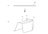
図2(a)に示すように、平板の金属板からなるブランク材10を、単純に、プレス成形時にフランジが伸ばされる変形が付与される図2(b)に示すようなプレス成形品11にプレス加工してみた。このとき、金属板10にハイテン材を適用してプレス成形すると、図2(b)中、符号Aで示す部位で、伸びフランジ割れが発生した。この伸びフランジ割れの発生の有無は、材料強度(引張強度)、材料組織、せん断端面状態、表面処理等に依存する。<About action and others>
As shown in FIG. 2A, a
例えば超ハイテン材にみられる複合組織の材料の場合、組織の硬度差によって、単相組織の材料に比べて伸びフランジ成形性が低下する。
また伸びフランジ成形性は、伸びフランジ変形を受ける材料端部の切断方法に依存する。金属板を、例えばせん断加工で切断した場合、機械加工で作製した端面よりもダメージが大きく、不均一な端面状態になるため、伸びフランジ成形性が低下する。さらに、せん断加工の場合でもクリアランスにより伸びフランジ成形性が変化する。For example, in the case of a material having a composite structure found in an ultra-high-tensile material, the stretch flangeability is lower than that of a material having a single-phase structure due to a difference in hardness of the structure.
Stretch flange formability also depends on the method of cutting the material end that is subject to stretch flange deformation. When the metal plate is cut by, for example, shearing, the end face is more damaged than the end face produced by machining and becomes an uneven end face state, so that stretch flange formability is reduced. Furthermore, even in the case of shearing, the stretch flange formability changes due to the clearance.
このような伸びフランジ成形に不利な材料や加工条件により発生する伸びフランジ割れを低減するために、本実施形態のプレス成形品の製造方法では、伸びフランジ割れ危険領域のうち、せん断加工で割れの起点になりやすくなった金属板の端面を加熱し冷却してから、プレス成形を行う。
この結果、本実施形態では、前処理としての加熱・冷却によって、伸びフランジ割れ危険部の材料の組織変化、すなわち材料の軟化やひずみ除去が行われることで、伸びフランジ成形性が向上する。In order to reduce stretch flange cracks caused by such disadvantageous materials and processing conditions for stretch flange forming, in the method of manufacturing a press-formed product of the present embodiment, of the stretch flange crack danger area, cracks caused by shearing are reduced. Press molding is performed after heating and cooling the end face of the metal plate which is likely to be the starting point.
As a result, in the present embodiment, the structural change of the material of the stretch flange cracking dangerous portion, that is, the material is softened and the strain is removed by the heating and cooling as the pretreatment, thereby improving the stretch flange formability.
特に、金属板の端面及び端面近傍の少なくとも端面をターゲットとして、材料軟化のための加熱処理を行い、その後に冷却処理を行うことで、加熱による材料強度(引張強度)の軟化に伴う部品の疲労特性の低下を、最低限に抑えることが可能となる。
なお、先行文献3のような2つの板材を溶接した溶接端部を含む集合ブランク材に、本実施形態を適用したとき、溶接端部を含む領域が伸びフランジ割れ領域の場合には、次のような問題がある。すなわち、本実施形態では端面及びその近傍だけ、つまり端面を中心に加熱処理とその後の冷却処理が施されることになる。したがって、本実施形態を適用すると、相対的に引張強度が弱い溶接端部の端面でプレス成形時に割れが発生する可能性がある。このため、伸びフランジ割れ領域に溶接端部が存在するような金属板を対象としたプレス成形品の製造は、本実施形態の対象外である。In particular, heat treatment for material softening is performed by using the end face of the metal plate and at least the end face near the end face as a target, and then the cooling process is performed, whereby the fatigue of the component due to the softening of the material strength (tensile strength) due to heating is achieved. Deterioration of the characteristics can be minimized.
In addition, when this embodiment is applied to the collective blank material including the welded ends where the two plate materials are welded as in the
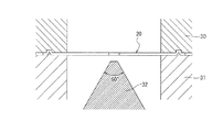
本発明に係るプレス成形方法による伸びフランジ成形性の向上効果を確認するため、穴広げ試験の試験片を部分的に加熱・空冷した後に穴広げ試験を実施した。その結果を以下に説明する。
本実施例では図3に示す穴広げ試験により伸びフランジ成形性を評価した。図3中、符号20がブランク材を、符号30がダイを、符号31がブランクホルダーを、符号32がパンチをそれぞれ示す。In order to confirm the effect of improving the stretch flange formability by the press forming method according to the present invention, a hole-expanding test was performed after partially heating and air-cooling the test piece in the hole-expanding test. The results are described below.
In this example, stretch flange formability was evaluated by the hole expansion test shown in FIG. In FIG. 3,
まず、図4に示すように、100[mm]×100[mm]角の正方形のブランク材に対し、ブランク中心にクリアランス12%でφ10[mm]の穴を打ち抜いて、穴広げ試験片(図3におけるブランク材20)を作製した。本実施例で使用したブランク材を構成する金属板は、板厚t=1.2mm、引張強度が1180MPa級鋼板とした。
作製した穴広げ試験片に対し、伸びフランジ成形を含むプレス加工を模して、図3のように、円錐型のパンチ32により穴広げ試験を実施した。しわ押さえ力は8tonに設定した。First, as shown in FIG. 4, a hole of φ10 [mm] was punched out with a clearance of 12% at the center of a blank from a square blank material of 100 [mm] × 100 [mm] square, and a hole expanding test piece (FIG. The blank material 20) in No. 3 was produced. The metal plate constituting the blank used in this example was a steel plate having a thickness t = 1.2 mm and a tensile strength of 1180 MPa class.
The produced hole expanding test piece was subjected to a hole expanding test using a
このとき、穴広げ試験の前処理として加熱処理しない条件(従来法)と、加熱処理を施す条件(本発明)とで、それぞれ穴広げ試験を実施した。
加熱処理の加熱条件としては、加熱装置にレーザーを使用してブランク材20の表面側を加熱し、加熱領域は金属板穴縁から1mm以上8mm以下の端縁領域とした。また加熱温度は、レーザー加熱面温度を200℃以上700℃以下の範囲でそれぞれ行った。
また、空冷(冷却)は、加熱装置で加熱した加熱部分が常温に温度降下するまで自然空冷を行うことで実施した。
表1に加熱条件及び穴広げ試験結果をまとめて示す。At this time, the hole-expansion test was carried out under the condition that no heat treatment was performed as a pretreatment of the hole-expansion test (conventional method) and the condition that heat treatment was performed (the present invention).
As the heating conditions of the heating treatment, the surface side of the
Air cooling (cooling) was performed by performing natural air cooling until the temperature of the heated portion heated by the heating device dropped to room temperature.
Table 1 summarizes the heating conditions and the results of the hole expanding test.

表1から分かるように、No.1は、加熱をしていないサンプルを穴広げ試験した結果であり、その穴広げ率は23%であった。この結果に対して、本発明に基づくNo.2〜No.5は、穴縁(穴の端面位置)から1mmの範囲をレーザー加熱し、穴広げ試験した結果であり、穴広げ率が向上していることが分かった。
また、No.6〜No.9は穴縁から3mmの範囲、No.10〜No.13は穴縁から5mmの範囲、No.14〜No.17は穴縁から8mmの範囲、をそれぞれレーザー加熱し、穴広げ試験を行った結果である。この場合においても、No.2〜No.5と同様に、加熱温度の上昇に伴い穴広げ率が向上することが分かった。As can be seen from Table 1, no. 1 is a result of a hole expanding test of a sample that was not heated, and the hole expanding ratio was 23%. On the basis of this result, No. 3 according to the present invention. 2-No. No. 5 is a result of performing a hole expanding test by laser heating a range of 1 mm from the hole edge (end surface position of the hole), and it was found that the hole expanding ratio was improved.
No. 6-No. No. 9 is within 3 mm from the hole edge. 10-No. No. 13 is within a range of 5 mm from the hole edge. 14-No. 17 is the result of performing a hole opening test by laser heating a range of 8 mm from the hole edge. Also in this case, No. 2-No. As in the case of No. 5, it was found that the hole expanding ratio was improved with an increase in the heating temperature.
表1から分かるように、本発明の範囲内では、各加熱温度が高い場合、加熱領域が穴広げ率に与える影響を比較すると、加熱領域が広い方が穴広げ率が向上することが分かる。ただし、加熱によって生じる材料強度(引張強度)の軟化に伴う部品の疲労特性の低下を考慮すると、フランジ割れ発生を抑制可能な範囲で、できるだけ端面からの加熱領域の範囲を小さく設定することが好ましい。またこの観点から、加熱温度も、例えば400℃以上600℃以下の範囲とすることが好ましい。 As can be seen from Table 1, within the scope of the present invention, when the respective heating temperatures are high, when the effects of the heating region on the hole expansion ratio are compared, it is found that the larger the heating region, the higher the hole expansion ratio. However, in consideration of the deterioration of the fatigue characteristics of the part due to the softening of the material strength (tensile strength) caused by heating, it is preferable to set the range of the heating region from the end face as small as possible within a range where the occurrence of flange cracking can be suppressed. . Also, from this viewpoint, the heating temperature is preferably set in a range of, for example, 400 ° C. or more and 600 ° C. or less.
ここで、本願が優先権を主張する、日本国特許出願2017−247992(2017年12月25日出願)の全内容は、参照により本開示の一部をなす。ここでは、限られた数の実施形態を参照しながら説明したが、権利範囲はそれらに限定されるものではなく、上記の開示に基づく各実施形態の改変は当業者にとって自明なことである。 Here, the entire contents of Japanese Patent Application No. 2017-247992 (filed on December 25, 2017), to which the present application claims priority, are incorporated by reference. Although the present invention has been described with reference to a limited number of embodiments, the scope of rights is not limited thereto, and modifications of the embodiments based on the above disclosure will be obvious to those skilled in the art.
1 せん断工程
2 加熱工程
3 冷却工程
4 プレス加工工程
5 伸びフランジ割れ領域推定処理
10 金属板(ブランク材)
11 プレス成形品
20 ブランク材DESCRIPTION OF SYMBOLS 1
11 Press-formed
Claims (7)
上記単一の金属板を上記プレス加工でプレス成形した際に、上記金属板の外周部における、伸びフランジ割れが発生しやすいと推定される領域の位置を特定する処理を行い、その特定した領域を伸びフランジ割れ領域とした場合に、
上記せん断加工後の単一の金属板における、上記伸びフランジ割れ領域内に位置する金属板端面及びその近傍のうち、せん断加工で割れの起点になりやすくなった金属板端面を加熱し冷却してから、上記プレス加工を施すことを特徴とするプレス成形品の製造方法。 A method of manufacturing a press-formed product in which a single metal plate formed by shearing a metal plate made of one plate material into a predetermined outer peripheral contour shape is subjected to press working including stretch flange forming. At
When the single metal plate is press-formed by the press working, the outer peripheral portion of the metal plate is subjected to a process of specifying a position of an area where it is estimated that stretch flange cracks are likely to occur , and the specified area Is the stretch flange crack area,
In the single metal plate after the shearing, the metal plate end surface located in the stretch flange crack region and the vicinity thereof, the metal plate end surface which is likely to be a starting point of the crack by the shearing process is heated and cooled. A method for producing a press-formed product, comprising:
0[mm] ≦ X ≦ 20[mm] ・・・(1) In the single metal plate surface, the heating range X [mm] from the end face position of the metal plate at the time of the heating, claims 1 to 5, characterized in that in the range of (1) The method for producing a press-formed product according to any one of the above items.
0 [mm] ≦ X ≦ 20 [mm] (1)
Applications Claiming Priority (3)
| Application Number | Priority Date | Filing Date | Title |
|---|---|---|---|
| JP2017247992 | 2017-12-25 | ||
| JP2017247992 | 2017-12-25 | ||
| PCT/JP2018/046409 WO2019131289A1 (en) | 2017-12-25 | 2018-12-17 | Method for manufacturing press formed product |
Publications (2)
| Publication Number | Publication Date |
|---|---|
| JP6624353B2 true JP6624353B2 (en) | 2019-12-25 |
| JPWO2019131289A1 JPWO2019131289A1 (en) | 2019-12-26 |
Family
ID=67067161
Family Applications (1)
| Application Number | Title | Priority Date | Filing Date |
|---|---|---|---|
| JP2019538273A Active JP6624353B2 (en) | 2017-12-25 | 2018-12-17 | Manufacturing method of press-formed product |
Country Status (7)
| Country | Link |
|---|---|
| US (1) | US11511330B2 (en) |
| EP (1) | EP3733320A4 (en) |
| JP (1) | JP6624353B2 (en) |
| KR (1) | KR102340442B1 (en) |
| CN (1) | CN111565863A (en) |
| MX (1) | MX2020006701A (en) |
| WO (1) | WO2019131289A1 (en) |
Families Citing this family (5)
| Publication number | Priority date | Publication date | Assignee | Title |
|---|---|---|---|---|
| US11511330B2 (en) | 2017-12-25 | 2022-11-29 | Jfe Steel Corporation | Method for manufacturing press formed product |
| CN113474100B (en) * | 2019-02-27 | 2023-06-16 | 杰富意钢铁株式会社 | Method for manufacturing steel sheet for cold pressing and method for manufacturing press member |
| JP7264090B2 (en) * | 2020-03-06 | 2023-04-25 | Jfeスチール株式会社 | METHOD FOR MANUFACTURING STEEL PLATE FOR PRESSING, METHOD FOR MANUFACTURING PRESSED PARTS, AND METHOD FOR EVALUATING STRETCH FLANGING FORMABILITY |
| KR20210155437A (en) * | 2020-06-15 | 2021-12-23 | 삼성디스플레이 주식회사 | Window molding apparatus and window molding method using the same |
| KR102402484B1 (en) | 2021-12-27 | 2022-05-26 | 김은조 | Press-Formed Product Manufacturing Method |
Family Cites Families (21)
| Publication number | Priority date | Publication date | Assignee | Title |
|---|---|---|---|---|
| US4122700A (en) * | 1976-09-02 | 1978-10-31 | Armco Steel Corporation | Process for forming sheet metal stock |
| JP2783490B2 (en) | 1993-02-02 | 1998-08-06 | 本田技研工業株式会社 | Manufacturing method of collective blank members |
| JPH08117879A (en) | 1994-08-29 | 1996-05-14 | Toyota Motor Corp | Pressing method |
| JP2001323318A (en) * | 2000-05-15 | 2001-11-22 | High Frequency Heattreat Co Ltd | Method for forming sheet |
| JP3762861B2 (en) | 2000-10-05 | 2006-04-05 | 新日本製鐵株式会社 | Manufacturing method of steel plate press-formed body |
| JP2004124151A (en) * | 2002-10-01 | 2004-04-22 | Japan Science & Technology Corp | Heat treatment method for aluminum alloy |
| DE102007008117B8 (en) * | 2007-02-19 | 2009-04-23 | Voestalpine Anarbeitung Gmbh | Method and device for tempered forming of hot-rolled steel material |
| JP2010227954A (en) * | 2009-03-26 | 2010-10-14 | Furukawa-Sky Aluminum Corp | Method of press-forming aluminum alloy sheet |
| DE102009014670B4 (en) * | 2009-03-27 | 2011-01-13 | Thyssenkrupp Sofedit S.A.S | Method and hot forming plant for the production of press-hardened shaped components from sheet steel |
| JP5825119B2 (en) * | 2011-04-25 | 2015-12-02 | Jfeスチール株式会社 | High-strength steel sheet with excellent workability and material stability and method for producing the same |
| CN105734404B (en) * | 2011-07-21 | 2018-01-02 | 株式会社神户制钢所 | The manufacture method of hot forming steel member |
| RU2598065C2 (en) * | 2012-05-17 | 2016-09-20 | Ниппон Стил Энд Сумитомо Метал Корпорейшн | Method for metal forming and a device for plastic working |
| JP6655863B2 (en) * | 2013-07-12 | 2020-03-04 | キヤノンファインテックニスカ株式会社 | Sheet bundle binding device and image forming system having the same |
| JP5765496B2 (en) * | 2013-07-19 | 2015-08-19 | Jfeスチール株式会社 | Press molding method and manufacturing method of press molded parts |
| DE102014016614A1 (en) * | 2014-10-31 | 2016-05-04 | Salzgitter Flachstahl Gmbh | Process for producing a component by forming a steel circuit board |
| US11000890B2 (en) * | 2014-12-25 | 2021-05-11 | Nippon Steel Corporation | Panel-shaped formed product and method for producing panel-shaped formed product |
| WO2017190220A1 (en) * | 2016-05-04 | 2017-11-09 | Magna International Inc. | Hot forming tool with infrared light source |
| CN106064193B (en) * | 2016-07-01 | 2018-10-26 | 华侨大学 | A kind of blanking method of ultra-high strength steel plate |
| DE102016121905A1 (en) * | 2016-11-15 | 2018-05-17 | Salzgitter Flachstahl Gmbh | Method for producing dual-phase steel wheel discs with improved cold workability |
| JP6958214B2 (en) * | 2017-10-16 | 2021-11-02 | 日本製鉄株式会社 | Manufacturing method of processed steel parts |
| US11511330B2 (en) | 2017-12-25 | 2022-11-29 | Jfe Steel Corporation | Method for manufacturing press formed product |
-
2018
- 2018-12-17 US US16/957,122 patent/US11511330B2/en active Active
- 2018-12-17 MX MX2020006701A patent/MX2020006701A/en unknown
- 2018-12-17 JP JP2019538273A patent/JP6624353B2/en active Active
- 2018-12-17 CN CN201880083421.1A patent/CN111565863A/en active Pending
- 2018-12-17 EP EP18897134.5A patent/EP3733320A4/en active Pending
- 2018-12-17 WO PCT/JP2018/046409 patent/WO2019131289A1/en unknown
- 2018-12-17 KR KR1020207017270A patent/KR102340442B1/en active IP Right Grant
Also Published As
| Publication number | Publication date |
|---|---|
| JPWO2019131289A1 (en) | 2019-12-26 |
| US11511330B2 (en) | 2022-11-29 |
| KR20200087229A (en) | 2020-07-20 |
| EP3733320A4 (en) | 2021-03-10 |
| CN111565863A (en) | 2020-08-21 |
| KR102340442B1 (en) | 2021-12-16 |
| WO2019131289A1 (en) | 2019-07-04 |
| EP3733320A1 (en) | 2020-11-04 |
| US20200346269A1 (en) | 2020-11-05 |
| MX2020006701A (en) | 2020-08-20 |
Similar Documents
| Publication | Publication Date | Title |
|---|---|---|
| JP6624353B2 (en) | Manufacturing method of press-formed product | |
| US10286439B2 (en) | Hot stamping method | |
| JP2000117338A (en) | Elongating process for forming aluminum alloy subjected to age hardening | |
| KR101494113B1 (en) | Press-molded article and method for producing same | |
| KR20170077192A (en) | Method for producing a component by subjecting a sheet bar of steel to a forming process | |
| Merklein et al. | Tailoring material properties of aluminum by local laser heat treatment | |
| US20190291160A1 (en) | Method for machining a sheet-metal profile | |
| JPWO2016143820A1 (en) | Burring method | |
| US9127330B2 (en) | Method of shaping and hardening a sheet steel blank | |
| RU2743046C1 (en) | Method for producing a component as a result of additional forming of a pre-formed circuit | |
| US9067251B2 (en) | Method of forming an article from metal alloy sheet material | |
| JP2019111567A (en) | Manufacturing method of press forming article | |
| JP6005539B2 (en) | Method for producing high strength 7000 series aluminum alloy member | |
| WO2021200233A1 (en) | Method for manufacturing pressed component, method for manufacturing blank material, and steel sheet | |
| US11192162B2 (en) | Method and device for forming a semi-finished product | |
| JP7276428B2 (en) | Method for manufacturing steel plate for cold press and method for manufacturing pressed part | |
| JP2012152780A (en) | Molding working method for aluminum alloy plate | |
| JP2008246555A (en) | Blank for press forming and press forming method | |
| US20220341015A1 (en) | Aluminum forming method | |
| RU2743047C1 (en) | Method for optimized production of a component with at least one formed auxiliary element | |
| WO2012043834A1 (en) | Press formed article and production method for same |
Legal Events
| Date | Code | Title | Description |
|---|---|---|---|
| A521 | Request for written amendment filed |
Free format text: JAPANESE INTERMEDIATE CODE: A523 Effective date: 20190712 |
|
| A621 | Written request for application examination |
Free format text: JAPANESE INTERMEDIATE CODE: A621 Effective date: 20190712 |
|
| A871 | Explanation of circumstances concerning accelerated examination |
Free format text: JAPANESE INTERMEDIATE CODE: A871 Effective date: 20190712 |
|
| A975 | Report on accelerated examination |
Free format text: JAPANESE INTERMEDIATE CODE: A971005 Effective date: 20191015 |
|
| TRDD | Decision of grant or rejection written | ||
| A01 | Written decision to grant a patent or to grant a registration (utility model) |
Free format text: JAPANESE INTERMEDIATE CODE: A01 Effective date: 20191029 |
|
| A61 | First payment of annual fees (during grant procedure) |
Free format text: JAPANESE INTERMEDIATE CODE: A61 Effective date: 20191111 |
|
| R150 | Certificate of patent or registration of utility model |
Ref document number: 6624353 Country of ref document: JP Free format text: JAPANESE INTERMEDIATE CODE: R150 |
|
| R250 | Receipt of annual fees |
Free format text: JAPANESE INTERMEDIATE CODE: R250 |
|
| R250 | Receipt of annual fees |
Free format text: JAPANESE INTERMEDIATE CODE: R250 |