WO2019131265A1 - 吸収性物品 - Google Patents
吸収性物品 Download PDFInfo
- Publication number
- WO2019131265A1 WO2019131265A1 PCT/JP2018/046290 JP2018046290W WO2019131265A1 WO 2019131265 A1 WO2019131265 A1 WO 2019131265A1 JP 2018046290 W JP2018046290 W JP 2018046290W WO 2019131265 A1 WO2019131265 A1 WO 2019131265A1
- Authority
- WO
- WIPO (PCT)
- Prior art keywords
- width direction
- absorbent core
- pair
- slit
- slits
- Prior art date
Links
Images
Classifications
-
- A—HUMAN NECESSITIES
- A61—MEDICAL OR VETERINARY SCIENCE; HYGIENE
- A61F—FILTERS IMPLANTABLE INTO BLOOD VESSELS; PROSTHESES; DEVICES PROVIDING PATENCY TO, OR PREVENTING COLLAPSING OF, TUBULAR STRUCTURES OF THE BODY, e.g. STENTS; ORTHOPAEDIC, NURSING OR CONTRACEPTIVE DEVICES; FOMENTATION; TREATMENT OR PROTECTION OF EYES OR EARS; BANDAGES, DRESSINGS OR ABSORBENT PADS; FIRST-AID KITS
- A61F13/00—Bandages or dressings; Absorbent pads
- A61F13/15—Absorbent pads, e.g. sanitary towels, swabs or tampons for external or internal application to the body; Supporting or fastening means therefor; Tampon applicators
- A61F13/45—Absorbent pads, e.g. sanitary towels, swabs or tampons for external or internal application to the body; Supporting or fastening means therefor; Tampon applicators characterised by the shape
- A61F13/49—Absorbent articles specially adapted to be worn around the waist, e.g. diapers
- A61F13/494—Absorbent articles specially adapted to be worn around the waist, e.g. diapers characterised by edge leakage prevention means
-
- A—HUMAN NECESSITIES
- A61—MEDICAL OR VETERINARY SCIENCE; HYGIENE
- A61F—FILTERS IMPLANTABLE INTO BLOOD VESSELS; PROSTHESES; DEVICES PROVIDING PATENCY TO, OR PREVENTING COLLAPSING OF, TUBULAR STRUCTURES OF THE BODY, e.g. STENTS; ORTHOPAEDIC, NURSING OR CONTRACEPTIVE DEVICES; FOMENTATION; TREATMENT OR PROTECTION OF EYES OR EARS; BANDAGES, DRESSINGS OR ABSORBENT PADS; FIRST-AID KITS
- A61F13/00—Bandages or dressings; Absorbent pads
- A61F13/15—Absorbent pads, e.g. sanitary towels, swabs or tampons for external or internal application to the body; Supporting or fastening means therefor; Tampon applicators
- A61F13/53—Absorbent pads, e.g. sanitary towels, swabs or tampons for external or internal application to the body; Supporting or fastening means therefor; Tampon applicators characterised by the absorbing medium
Definitions
- the present invention relates to absorbent articles such as disposable diapers.
- An absorbent article such as a disposable diaper described in Patent Document 1 includes a front waist area disposed around the wearer's front waist, a back waist area disposed around the wearer's back waist, and the wearer's crotch. And a crotch region to be disposed.
- An absorbent core for absorbing the body fluid of the wearer extends from the front waist area to the back waist area.
- a sheet-like elastic element that can expand and contract in the width direction is provided in the rear waist region.
- the absorbent core has a low stiffness region where the basis weight is lower than in other parts of the absorbent core or the absorbent core is not present.
- the low stiffness region extends forward from the rear edge of the absorbent core at the center of the absorbent core in the width direction.
- the low rigidity region of the absorbent core and the sheet-like elastic element are considered to increase the fit to the buttocks of the wearer.
- absorbent articles such as disposable diapers
- the inventor of the present application has found an absorbent article which makes it easier to deform the portion of the absorbent core corresponding to the buttocks of the wearer into a cup shape during wearing, and can suppress the leakage of body fluid.
- a crotch disposed between the front and rear direction, the width direction orthogonal to the front and rear direction, a front waist area, a rear waist area, the front waist area, and the rear waist area It has an area
- the absorbent core has a pair of rear slits located on both sides of the center in the width direction. The pair of rear slits extend forward from the rear edge in the rear waist region. The length in the width direction of the rear side edge of the rear side slit is longer than the length in the width direction of the front side edge of the rear side slit.
- a crotch disposed between the front and rear direction, the width direction orthogonal to the front and rear direction, a front waist area, a rear waist area, the front waist area, and the rear waist area A region, an absorbent core extending at least from the crotch region to the rear waist region, and an elastic member that expands and contracts in the width direction in the rear waist region, and the absorbent core sandwiches the center in the width direction It has a pair of rear side slits located on both sides, and the pair of rear side slits extend from the rear side edge to the front side in the rear waist region, and the width direction of the rear side edge of the rear side slit The length of the rear slit is longer than the length of the front edge of the rear slit in the width direction.
- the rear waist region tries to shrink inward in the width direction by an elastic member that expands and contracts in the width direction.
- the absorbent core has a rear side slit extending from the rear side edge to the front side in the rear waist region, and the length in the width direction of the rear side edge of the rear side slit corresponds to that of the front side edge of the rear side slit It is longer than the length in the width direction. Therefore, the absorbent core is more likely to be deformed inward in the width direction by the action of the elastic member toward the rear.
- the outer end in the width direction of the absorbent core is deformed so as to be directed to the skin side.
- the portion of the absorbent core corresponding to the buttocks of the wearer tends to have a cup shape corresponding to the curvature of the buttocks of the wearer.
- the outer outline in the width direction of the pair of rear slits has a portion that is inclined toward the rear side and the outer side in the width direction.
- the outer outline in the width direction of the pair of rear slits has a portion that is inclined toward the rear side and the outer side of the width direction.
- the widthwise length of the absorbent core between the pair of rear slits has a region which becomes longer from the front end edge of the pair of rear slits toward the rear side.
- the width of the absorbent core between the pair of rear slits is wider toward the rear side, leakage of body fluid from the rear (back side) can be suppressed. it can.
- the length in the width direction of the absorbent core between the pair of rear slits is maximum on the front side of the rear end edge of the absorbent core.
- the absorbent core between the pair of rear slits When the length in the width direction of the absorbent core between the pair of rear slits is maximum at the rear end edge of the absorbent core, when the absorbent core is deformed inward in the width direction, the distance between the rear slits is The rear edge of the absorbent core may hit the rear edge of the absorbent core adjacent to the outside in the width direction of the rear slit, and the absorbent core may not be deformed sufficiently to close the rear slit during wearing.
- the absorbent core since the length in the width direction of the absorbent core between the pair of rear slits is maximum on the front side of the rear end edge of the absorbent core, the absorbent core is sufficiently absorbed to close the rear slits during wearing.
- the core can be deformed.
- the maximum length of the rear slit in the width direction is 5 mm or more.
- the absorbent core in the rear waist region can be easily deformed by the cup shape.
- the rear slit has a maximum length in the width direction at the rear edge of the absorbent core.
- the absorbent core is more likely to be deformed inward in the width direction toward the rear side.
- the absorbent core is more easily deformed to form a cup shape.
- the difference between the maximum length of the rear slit in the width direction and the length of the front end edge of the rear slit in the width direction is 10 mm or more.
- the absorbent core forms a cup shape more in the rear waist region It becomes easy to According to a preferred aspect, the front end edge of the rear slit is pointed inward in the width direction.
- the absorbent core on the outer side of the rear slit is more likely to be deformed inward, centering on the front end edge of the rear slit. Therefore, the absorbent core is more easily deformed to form a cup shape in the rear waist region.
- the maximum width of the absorbent core between the pair of rear slits is 15 mm or more.
- the absorbent core has a central slit extending from the rear edge toward the front, between the pair of rear slits, and the length of the central slit in the front-rear direction is It is shorter than the length of the pair of slits in the front-rear direction.
- the absorbent core is more likely to be deformed inward in the rear waist region. Even in this case, since the length of the central slit in the front-rear direction is shorter than the length of the pair of slits in the front-rear direction, it is possible to suppress the leakage of the body fluid from the rear (back side).
- At least a part of the pair of rear slits overlaps the elastic member in the thickness direction.
- the absorbent core is more likely to be deformed inward in the rear waist region.
- the entire pair of rear slits overlap the elastic member in the thickness direction.
- the absorbent core is more easily deformed inward in the rear waist region.
- the contraction force in the width direction of the rear waist region at the position of the rear end edge of the rear slit is the width of the rear waist region at the position of the front end edge of the rear slit. Greater than the contraction force in the direction.
- the absorbent core can be more easily deformed in the width direction on the rear edge than on the front edge of the rear slit. As a result, the absorbent core is more easily deformed to form a cup shape.
- the back leakage slit includes a pair of leakage preventing cuffs extending in the front-rear direction at least in the crotch region and disposed on both sides across the center in the width direction, It is provided behind the standable portion of
- the leak-barrier cuff extending in the front-rear direction shrinks back and forth, if the rear side slit of the absorbent core is provided on the front side of the erected region of the leak-barrier cuff, the force pulled in the forward direction from the The absorbent core is less likely to be deformed inward in the width direction, and is less likely to be cup-shaped. Therefore, in order to make the absorbent core into a cup shape in the rear waist region, the rear slit is preferably provided on the rear side of the erected region of the leak-barrier cuff.
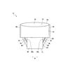
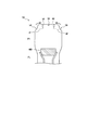
- FIG. 1 is a schematic view of an absorbent article according to an embodiment.
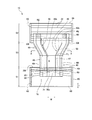
- FIG. 2 is a developed plan view of the absorbent article according to one embodiment.
- FIG. 2 shows an expanded state in which the absorbent article is expanded to a state in which no wrinkles are formed in the expanded state in which side locking portions described later are expanded.
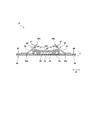
- FIG. 3 is a cross-sectional view of the absorbent article taken along the line AA of FIG.
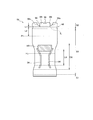
- FIG. 4 is a plan view of the absorbent core of the absorbent article.
- the absorbent article 10 has an anteroposterior direction L and a width direction W orthogonal to each other in the unfolded state.
- the front-rear direction L is defined by the direction extending to the body front side (ventral side) and the body rear side (back side).
- the front-rear direction L is a direction extending in the front-rear direction in the developed absorbent article 10.
- the absorbent article 10 has a thickness direction T orthogonal to both the front-rear direction L and the width direction W.
- the absorbent article 10 has a front waist area S1, a back waist area S2, and a crotch area S3.
- the front waist area S1 is an area facing the front waist of the wearer.
- the back waist area S2 is an area facing the back waist of the wearer.
- the crotch region S3 is a region located under the wearer's crotch and disposed between the front waist region S1 and the rear waist region S2.
- the absorbent article 10 may have a front waistline member 20, a back waistline member 30, and an absorbent main body 40.
- the front waist member 20 is disposed in the front waist region S1.
- the rear waistline member 30 is disposed in the rear waistline region S2.
- the front waistline member 20 and the rear waistline member 30 may be made of, for example, a non-woven sheet.
- the front waist member 20 may have, for example, a non-skin side sheet 14 in two layers and a cover sheet 70 in two layers.
- the non-skin side sheet 14 and the cover sheet 70 are formed of an integral sheet.
- the cover sheet 70 is configured by folding the non-skin side sheet 14 at the front end edge of the front waist area S1.
- the non-skin side sheet 14 and the cover sheet 70 may be composed of separate sheets.
- a fold line FL that divides the absorbent article 10 back and forth may pass through the crotch area S3.
- the fold line FL extends in the width direction W. That is, in the state shown in FIG. 1, the absorbent article 10 is folded in half with the fold line FL extending along the width direction W as a base point.
- Side locking portions 60 may be provided at the end of the front waist area S1 in the width direction W and at the end of the rear waist area S2 in the width direction W.
- the side locking portion 60 is defined by a portion in which an end of the front waist area S1 in the width direction W and an end of the rear waist area S2 in the width direction W are mutually locked.
- the absorbent article 10 can A torso opening 62 through which the torso is passed and a pair of leg openings 66 to which the wearer's legs are respectively inserted are formed.
- the waist opening edge 64 forming the waist opening 62 may be defined by the front end edge of the front waist member 20 and the rear edge of the rear waist member 30.
- the leg opening edge 68 forming the leg opening 66 includes a side 40 l of the absorbent main body 40 extending in the front-rear direction L, a side 20 l located on the rear side of the front waist member 20, and a rear waist member 30. May be defined by the side 30l located on the front side of.
- FIG. 2 shows a state in which the locking in the side locking portion 60 is released, and the absorbent article 10 is developed.
- the side locking portion 60 may extend in the front-rear direction L in each of the front waist portion 20 and the rear waist portion 30.
- the boundary between the front waistline region S1 and the crotch region S3 may be defined by the rear end edge of the side engagement portion 60 provided on the front waistline member 20.
- the boundary between the back waist area S2 and the crotch area S3 may be defined by the front end edge of the side locking portion 60 provided on the back waist part 30.
- One or more elastic members 32 that can expand and contract in the width direction W may be provided in the rear waist region S2.
- the elastic member 32 in the rear waist region S2 may be configured by an expandable sheet that can expand and contract in the width direction W.
- the elastic member 32 may be provided at a position at least partially overlapping the absorbent core 51.
- one or more second elastic members 22 that can expand and contract in the width direction W may be provided.
- the second elastic member 22 is made of an elastic thread.
- the second elastic member 22 may be provided on the non-skin surface side of the absorbent main body 40 in the front waist area S1.
- an elastic sheet 90 that can expand and contract in the width direction W may be provided in the front waist area S1.
- the stretchable sheet 90 may be provided in a region not overlapping the second elastic member 22 in the thickness direction T.
- the absorbent main body 40 includes at least an absorbent 50. Furthermore, the absorbent main body 40 may have the skin sheet 41 located on the skin surface side of the absorber 50 and the non-skin surface sheet 42 located on the non-skin surface side of the absorber 50. The skin side sheet 41 may cover the absorber 50 on the skin side of the absorber 50. The non-skin surface sheet 42 may cover the absorber 50 on the non-skin surface side of the absorber 50.
- the skin sheet 41 may be made of, for example, a liquid-permeable sheet such as a non-woven fabric or a perforated plastic film.
- the skin sheet 41 may be composed of one sheet. Instead of this, the skin sheet 41 may be composed of a laminated sheet in which a plurality of sheets are laminated to one another.
- the non-skin sheet 42 may include a liquid-impervious sheet.
- the liquid-impervious sheet may be constituted by a liquid-impervious film such as, for example, a plastic film.
- the non-skin surface sheet 42 may be composed of one sheet. Instead of this, the non-skin surface sheet 42 may be composed of a laminated sheet in which a plurality of sheets are laminated to one another. In this case, at least one of the plurality of sheets may have liquid impermeability.
- the absorbent 50 may include an absorbent core 51 and a core wrap 52 that wraps around the absorbent core.
- the absorbent core 51 may comprise, for example, ground pulp or superabsorbent polymer (SAP), or a mixture thereof.
- the core wrap 52 may be made of, for example, a tissue or a thin paper.
- the absorbent core 51 is disposed at least in the crotch region S3.
- the absorbent core 51 may extend from the front waist area S1 to the rear waist area S2 in the front-rear direction L.
- the absorbent core 51 may have a constricted area CA which is constricted in the width direction W at least in the crotch area S3.
- the constriction area CA may extend in the front-rear direction L with respect to the fold line FL.
- the narrowest portion LA of the absorbent core 51 in the width direction W may be provided in the crotch region S3.
- the narrowest portion of the absorbent core 51 may extend along the front-rear direction L.
- the fold line FW may pass through the constricted area CA of the absorbent core 51.
- the absorbent main body 40 may have a side sheet 43 that covers both sides of the skin sheet 41 in the width direction W.
- the side sheet 43 may be made of, for example, a sheet such as a non-woven fabric or a perforated plastic film.
- the absorbent body 40 may have a pair of leak-barrier cuffs 46.
- the pair of leak-barrier cuffs 46 extend in the front-rear direction L between the front waist area S1 and the rear waist area S2, and are disposed on both sides across the center of the absorbent article 10 in the width direction W.
- the pair of leak-barrier cuffs 46 is defined by a standable portion (portion in the range B in FIG. 2) which can stand up toward the wearer's skin.
- the leak-barrier cuff 46 may be configured of the side seat 43 and the third elastic member 47 provided on the side seat 43.
- the third elastic member 47 is configured to be extensible and contractible in the front-rear direction.
- the third elastic member 47 may include one or more thread rubbers.
- the inner part of the side sheet 43 in the width direction W is folded back to the outside, and the third elastic member 47 is disposed in the part where the side sheet 43 is folded back. Further, the inner edge of the side sheet 43 in the width direction W is not joined to the skin sheet 41, and constitutes a free end which can rise from the skin sheet 41.
- the leak-barrier cuff 46 has a rising point 46a and a rising point 46b.
- the rising support point 46a and the rising point 46b extend in the front-rear direction L from the front waist area S1 to the rear waist area S2.
- the rising support point 46 a is a point that does not stand up, and corresponds to the root of the leak-barrier cuff 46.
- the rising support point 46 a corresponds to an inner edge line in the width direction W of the joined portion of the side sheet 43 and the skin sheet 41.
- the rising apex 46 b corresponds to the top of the leak-barrier cuff 46 when the leak-barrier cuff 46 is lifted. That is, the rising apex 46 b is the free end of the leak-barrier cuff 46.
- the absorbent main body 40 may have a pair of gathers 48 in a region outside the pair of leak-barrier cuffs 46 in the width direction W.
- the pair of gathers 48 may extend in the front-rear direction L from the front waist area S1 to the rear waist area S2.
- the pair of gathers 48 may be constituted by a fourth elastic member 49 attached to the sheet constituting the absorbent main body 40.
- the fourth elastic member 49 may be, for example, one or more thread rubbers.
- the fourth elastic member 49 may be, for example, an elastic sheet having stretchability.
- the fourth elastic member 49 is joined to the sheet constituting the absorbent main body 40 in a state of being expanded from the natural state.
- the fourth elastic member 49 acts to contract the absorbent main body 40 in the front-rear direction L, and can form a gather.
- FIG. 4 is a plan view of the absorbent core 51 of the absorbent article 10.
- the absorbent core 51 may have a high rigidity region HR.
- the high rigidity region HR is provided in the region including the center in the width direction W behind the folding line FL.
- the high rigidity region HR is defined by a region having rigidity higher than the rigidity in the region between the fold line FL and the high rigidity region HR.
- the high rigidity region HR may be constituted by an embossed region in which the absorbent core 51 is compressed in the thickness direction.
- the absorbent core 51 may have a pair of grooves 54 formed on both sides with respect to the center of the absorbent article 10 in the width direction W.
- the “groove” of the absorbent core 51 is a concept including both a recess formed in the absorbent material constituting the absorbent core 51 or a region where the basis weight of the absorbent material is zero.
- the absorbent core 51 may have a rear slit 56 and a central slit 59 extending forward from the rear edge of the absorbent core 51 in the rear waist region S2.
- the absorbent core 51 may have a pair of side slits 58 located at both outer edges of the absorbent core 51 in the width direction W.
- the slit may be a region where the absorbent material constituting the absorbent core 51 is substantially zero.
- the inner edge located on the innermost side of the pair of side slits 58 in the width direction W is located on the rear side of the intermediate line P1 between the rear end edge of the absorbent core 51 and the fold line FL.
- the absorbent core 51 receives a force inward in the width direction W in the rear waist region S2.
- the pair of side slits 58 serves as a folding starting point of the absorbent core 51, and the absorbent core 51 is easily deformed toward the inside in the width direction W starting from the pair of side slits 58 in the rear waist region S2.
- the innermost inner edge portion of the pair of side slits 58 be positioned on the rear side of the narrowest portion LA where the width of the absorbent core 51 is the narrowest in the narrowed region CA.
- the constricted area CA of the absorbent core 51 is an area where the wearer is sandwiched by the legs. Therefore, the narrowed area CA has high rigidity due to the absorbent core 51 being crushed in the width direction.
- the innermost inner edge portion of the pair of side slits 58 is located behind the constricted area CA. As described above, by arranging the pair of side slits 58 at a position apart from the narrowed area CA, the function of deforming the absorbent core 51 starting from the side slits 58 can be further functioned.
- At least a part, preferably all, of the pair of side slits 58 be provided in a region overlapping with the side locking portion 60 when viewed in the width direction W.
- a region overlapping with the side locking portion 60 when viewed in the width direction W is a region that fits around the waist of the wearer. Therefore, the absorbent core 51 tends to receive a force inward in the width direction W in a region overlapping with the side locking portion 60.
- the outer portion in the width direction W of the absorbent core 51 in the rear waist region S2 is inward in the width direction W It becomes easy to lean and it becomes easy to become cup shape according to the curvature of a wearer's buttocks.
- the maximum length of the pair of side slits 58 in the front-rear direction L is preferably longer than the thickness of the absorbent core 51. More specifically, the maximum length of the pair of side slits 58 is preferably longer than the thickness of the portion of the absorbent core 51 adjacent to the side slits. Accordingly, when the absorbent core 51 is deformed into a cup shape in the rear waist region S2, overlapping of the absorbent cores 51 adjacent to each other in the front-rear direction L with the side slit 58 interposed therebetween can be suppressed. As a result, the absorbent core 51 tends to be in a cup shape that is rounded according to the wearer's body.
- the elastic member 32 in the rear waist region S2 may include a rear elastic member on the rear side of the pair of side slits 58 and a front elastic member on the front side of the pair of side slits 58.
- the contraction force of the rear elastic member is preferably higher than the contraction force of the front elastic member.
- an elastic member that expands and contracts in the width direction W may not be provided in the region between the folding line FL and the pair of side slits 58. That is, the above-mentioned front side elastic member does not need to be provided.
- the absorbent core 51 located behind the pair of side slits 58 receives a stronger force directed inward in the width direction W. Therefore, the outer portion in the width direction W of the absorbent core 51 in the back waist area S2 is deformed so as to be closer to the inner side in the width direction W, and tends to have a cup shape according to the curvature of the buttocks of the wearer.
- the absorbent core 51 preferably has a rear slit 56 extending forward from the rear end edge of the absorbent core 51.
- the absorbent core 51 in the rear waist region S ⁇ b> 2 tries to deform inward in the width direction W starting from the side slit 58.
- the absorbent core 51 is more easily deformed in the width direction W inside.
- the innermost portion of the side slit 58 in the width direction W is preferably provided on the front side of the front edge of the rear slit 56.
- distortion due to the deformation of the absorbent core 51 may occur up to the front edge of the rear slit 56.
- the side slit can alleviate this distortion. Therefore, the deformation of the absorbent core 51 in the rear waist region S2 is difficult to be transmitted to the crotch region S3, and it becomes easy to deform only the absorbent core 51 in the rear waist region S2 into a desired shape.
- the innermost portion of the side slit 58 in the width direction W is preferably located closer to the front edge of the rear slit 56 than the intermediate line P1 between the rear end edge of the absorbent core 51 and the fold line FL. . That is, a distance L1 in the front-rear direction between the innermost portion of the side slit 58 in the width direction W and the front edge of the rear slit 56 is the innermost portion of the side slit 58 in the width direction W It is shorter than the distance L2 in the front-rear direction with the middle line P1.
- the absorption core 51 on the rear side of the side slit 58 is obtained by the action of both the side slit 58 and the rear slit 56. It can be made easier to be deformed inward in the width direction W. As a result, the absorbent core 51 in the back waist area S2 is likely to have a cup shape according to the curvature of the buttocks of the wearer.
- the absorbent core 51 preferably has a pair of rear slits 56 positioned on both sides of the center in the width direction W.
- An absorbent core 51 is present between the pair of rear slits 56. Therefore, even when the body fluid is transmitted from the center in the width direction of the absorbent core 51 directly behind, the absorbent core 51 between the pair of rear slits 56 can absorb the body fluid. Thereby, even if the rear side slit 56 which makes the absorbent core 51 easy to deform is present, it is possible to suppress the leakage of the bodily fluid from the rear.
- the leak-barrier cuff 46 extended in the front-rear direction L shrinks back and forth, when the rear side slit 56 of the absorbent core 51 is provided on the front side of the erected area B of the leak-barrier cuff 46 The force of being pulled in the direction makes it difficult for the absorbent core 51 to be deformed inward in the width direction W, and it is difficult for the absorbent core 51 to have a cup shape. Therefore, in order to make it easy to make absorption core 51 cup-shaped in back waist area S2, it is preferred that back side slit 56 is provided in the back side rather than standing up possible part B of leakproof cuff 46.
- the length in the width direction W of the rear side edge of the rear side slit 56 is preferably longer than the length in the width direction W of the front side edge of the rear side slit 56.
- the rear waist region S ⁇ b> 2 tries to shrink inward in the width direction W by the elastic member 32 that expands and contracts in the width direction W.
- the length in the width direction of the rear side edge of the rear side slit 56 is longer than the length in the width direction W of the front side edge of the rear side slit 56. Therefore, the absorbent core 51 is more easily deformed inward in the width direction by the action of the elastic member 32 as it goes rearward.
- the outer end of the absorbent core 51 in the width direction is deformed toward the skin side while the absorbent core 51 on the outer side in the width direction is closer to the inside than the pair of rear slits 56 (FIG. 5) See also).
- the portion of the absorbent core corresponding to the buttocks of the wearer tends to have a cup shape corresponding to the curvature of the buttocks of the wearer.
- the outside outline 56-o of the width direction W of the pair of rear slits 56 have a portion that is inclined toward the rear side and the outside of the width direction W. More preferably, the entire outer outline 56-o of the pair of rear slits 56 in the width direction W is inclined toward the rear side and the outside in the width direction W.
- the outer outline 56 Brighton of the rear slit 56 is inclined, the rear edge of the outline 56schreib is located outside the front edge of the outline 56 1958 in the width direction W.
- the absorbent core 51 in the width direction W than the outline 56schreib is located outside the widthwise direction of the front edge of the outline 56 Gr serving as the deformation starting point. Therefore, when the absorbent core 51 in the back waist area S2 receives a force inside the width direction W, the absorbent core 51 outside the width direction W is more easily deformed to form a cup shape than the outline 56 gleich. Become.
- the outline 56i inside the width direction W of a pair of rear side slit 56 has a part which inclines toward the outer side of the width direction W while it goes back.
- the outer portion of the absorbent core 51 is more cup-shaped when the outer core 56i of the rear slit 56 is inclined obliquely and thus the absorbent core 51 in the rear waist area S2 receives a force inward in the width direction W. It is easy to deform to form
- the rear slit 56 preferably has a maximum length in the width direction W at the rear edge of the absorbent core 51. As a result, the absorbent core 51 is more likely to be deformed inward in the width direction W toward the rear side. As a result, in the rear waist region S2, the absorbent core 51 is more easily deformed to form a cup shape.
- the front end edge of the rear slit 56 is preferably pointed inward in the width direction W.
- the absorbent core 51 outside the rear slit 56 is more likely to be deformed inwardly about the front end edge of the rear slit 56. Therefore, the absorbent core 51 is more easily deformed to form a cup shape in the rear waist region S2.
- the maximum length of the rear slit 56 in the width direction W is preferably 5 mm or more.
- the difference between the maximum length of the rear slit 56 in the width direction W and the length of the front end edge of the rear slit 56 in the width direction W is preferably 10 mm or more.
- the length of the width direction W of the absorbent core 51 between the pair of rear slits 56 has a region which becomes longer from the front end edge of the pair of rear slits 56 toward the rear side. Since the width of the absorbent core 51 between the pair of rear slits 56 has a portion that widens toward the rear side, it is possible to suppress the leakage of the body fluid from the rear (back side).
- the length in the width direction W of the absorbent core 51 between the pair of rear slits 56 be maximum on the front side of the rear end edge of the absorbent core 51.
- the length in the width direction W of the absorbent core 51 between the pair of rear slits 56 is maximum at the rear end edge of the absorbent core 51, when the absorbent core 51 is deformed inward in the width direction W, The rear edge of the absorbent core 51 between the rear slits 56 abuts on the rear edge of the absorbent core 51 adjacent to the outer side in the width direction of the rear slit 56 so that the rear slit 56 is closed during wearing. In some cases, the absorbent core 51 does not deform.
- the rear slits are closed during wearing.
- the absorbent core 51 can be deformed sufficiently.
- the absorbent core 51 in the width direction outside of the pair of rear slits 56 can be deformed so as to be directed rearward of the absorbent core 51 between the pair of rear slits 56, so that It becomes easy to form a deformed state which presses the absorption core 51 toward. Therefore, it is possible to further suppress stool leakage from the rear.
- the maximum width of the absorbent core 51 between the pair of rear slits 56 is 15 mm or more.
- the absorbent core 51 may have a central slit 59 extending from the rear edge toward the front, between the pair of rear slits 56.
- the length of the central slit 59 in the front-rear direction L is preferably shorter than the length of the pair of rear slits 56 in the front-rear direction L. More preferably, the length of the central slit 59 in the width direction W is shorter than the length of the rear slit 56 in the width direction W.
- the elastic member 32 is formed of a stretchable sheet, all of the pair of rear slits 56 can overlap the elastic member 32 in the thickness direction T. Thereby, the contraction by the elastic member 32 easily acts on the rear slit 56 of the absorbent core 51, so the absorbent core 51 is more likely to be deformed inward in the rear waist region S2.
- the contraction force in the width direction W of the rear waist region S2 on the rear side than the rear slit 56 is larger than the contraction force in the width direction W of the rear waist region S2 on the front side than the rear slit 56 .
- the contraction force in the width direction W of the rear waist region S2 cut to a width of 3 cm to the rear side from the rear slit 56 is the width direction W of the rear waist region S2 cut to a width of 3 cm to the front side from the rear slit 56 Greater than the contractile force of When the distance between the rear edge of the rear slit 56 and the rear edge of the absorbent article is less than 3 cm, the entire rear region is cut away from the rear slit 56 in the width direction W of the rear waist S2.
- the contraction force of the rear slit 56 may be larger than the contraction force of the rear waist area S2 in the width direction W with the same width as the area of the rear slit 56 and the front side of the rear slit 56.
- the absorbent core 51 can be more easily deformed in the width direction W on the rear end edge side than on the front end edge of the rear side slit 56.
- the absorbent core 51 is more easily deformed to form a cup shape.
- the contraction force in the width direction W of the rear waist region S2 can be defined as follows.
- the contraction force can be measured by an electro-mechanical universal material tester (tensile tester: manufactured by INSTRON, INSTRON, model 5564). Specifically, first, a test piece to be measured is prepared. If the absorbent article has side joints, the side joints are released and the absorbent article is deployed. Next, in the stretched state in which the absorbent article is stretched, a test piece cut to a width of 3 cm from the rear slit 56 to the rear side and a test piece cut to a width of 3 cm to the front from the rear slit 56 are obtained. Do.
- the other of the chucks is reciprocated by two reciprocations so as to change the distance between the chucks.
- the moving speed of the chuck at this time is 300 mm / min.
- the timing to change the moving direction of the chuck is a point at 95% of the maximum extension.
- the stress applied to the chuck is measured, and the stress obtained at 60% from the maximum elongation is defined as the “contraction force” of each portion in the front waist area S1.
- the time of maximum expansion means the state extended to such an extent that a wrinkle does not generate
- the numerical values relating to the “length” of each part of the absorbent article 10 are the absorbent article until the wrinkles (except for the folding line FL) of the absorbent article 10 developed by releasing the side locking portion 60 disappear. Is measured in the extended state in which the
- the absorbent main body 40 is configured separately from the front waistline member 20 and the rear waistline member 30.
- the absorbent main body 40 may be integrally formed with the front waistline member 20 and the rear waistline member 30.
- the absorbent article 10 is a so-called pants-type absorbent article which has the side latching
- the absorbent article 10 may be a tape-type absorbent article.
- the absorbent article 10 may have a fastening tape that does not have the side locking portion 60 and that detachably fixes the front waist area S1 and the rear waist area S2 to each other.
- the fastening tape is provided in the back waist area S2, and fastens the back waist area S2 to the front waist area S1.
- the pair of side slits 58 is preferably provided on the front side of the fastening tape. The fastening tape is fastened while being pulled outward in the width direction.
- the pair of side slits 58 When the pair of side slits 58 is provided on the front side (crotch side) of the fastening tape, the inward contraction in the width direction at the position of the pair of side slits 58 is not inhibited. Therefore, the outer portion in the width direction of the absorbent core in the rear waist region tends to be closer to the inner side in the width direction, and tends to have a cup shape according to the curvature of the buttocks of the wearer.
- the part of the absorption core corresponding to a wearer's buttocks can be made easy to be changed into cup shape more, and the absorptive article which can control the leak of a bodily fluid can be provided.
- Absorbent article 40 Absorbent main body 50 Absorbent body 51 Absorbent core 54 Groove 56 Rear side slit 58 Side slit 59 Central slit CA Central area S1 Front waist area S2 Rear waist area S3 Crotch area FL Fold line L Front and back direction W Width direction T Thickness direction
Abstract
着用者の臀部に相当する吸収コアの部分をよりカップ形状に変形させ易くし、体液の漏れを抑制できる吸収性物品を提供することができる。吸収性物品(10)は、前後方向(L)と、前後方向に直交する幅方向(W)と、前胴回り域(S1)と、後胴回り域(S2)と、前胴回り域と後胴回り域との間に配置された股下域(S3)と、少なくとも股下域から後胴回り域にわたって延びる吸収コア(51)と、後胴回り域において幅方向に伸縮する弾性部材(32)と、を有する。吸収コアは、幅方向における中心を挟んで両側に位置する一対の後側スリット(56)を有する。一対の後側スリットは、後胴回り域において後側縁から前側に向けて延びている。後側スリットの後側縁の幅方向における長さは、後側スリットの前側縁の幅方向における長さよりも長い。
Description
本発明は、例えば使い捨ておむつのような吸収性物品に関する。
特許文献1に記載された使い捨ておむつのような吸収性物品は、着用者の前胴回りに配置される前胴回り域と、着用者の後胴回りに配置される後胴回り域と、着用者の股下に配置される股下域と、を有する。着用者の体液を吸収する吸収コアは、前胴回り域から後胴回り域にわたって延びている。
特許文献1に記載された吸収性物品では、後胴回り域に、幅方向において伸縮可能なシート状弾性要素が設けられている。吸収コアは、吸収コアの他の部位よりも目付けが低いまたは吸収コアが存在しない低剛性領域を有する。この低剛性領域は、幅方向における吸収コアの中心で、吸収コアの後側縁から前方に向かって延びている。特許文献1に記載された吸収性物品では、吸収コアの低剛性領域とシート状弾性要素とにより、着用者の臀部へのフィット性が高くなるとされている。
使い捨ておむつのような吸収性物品に関し、着用者の臀部へのフィット性や体液の漏れの抑制という課題については、未だ改善の余地がある。特に、本願の発明者は、着用中に、着用者の臀部に相当する吸収コアの部分をよりカップ形状に変形させ易くし、体液の漏れを抑制できる吸収性物品を見出した。
一態様に係る吸収性物品は、前後方向と、前記前後方向に直交する幅方向と、前胴回り域と、後胴回り域と、前記前胴回り域と前記後胴回り域との間に配置された股下域と、少なくとも前記股下域から前記後胴回り域にわたって延びる吸収コアと、前記後胴回り域において前記幅方向に伸縮する弾性部材と、を有する。前記吸収コアは、前記幅方向における中心を挟んで両側に位置する一対の後側スリットを有する。前記一対の後側スリットは、前記後胴回り域において後側縁から前側に向けて延びている。前記後側スリットの後側縁の前記幅方向における長さは、前記後側スリットの前側縁の前記幅方向における長さよりも長い。
(1)実施形態の概要
本明細書及び添付図面の記載により、少なくとも以下の事項が明らかとなる。
本明細書及び添付図面の記載により、少なくとも以下の事項が明らかとなる。
一態様に係る吸収性物品は、前後方向と、前記前後方向に直交する幅方向と、前胴回り域と、後胴回り域と、前記前胴回り域と前記後胴回り域との間に配置された股下域と、少なくとも前記股下域から前記後胴回り域にわたって延びる吸収コアと、前記後胴回り域において前記幅方向に伸縮する弾性部材と、を有し、前記吸収コアは、前記幅方向における中心を挟んで両側に位置する一対の後側スリットを有し、前記一対の後側スリットは、前記後胴回り域において後側縁から前側に向けて延びており、前記後側スリットの後側縁の前記幅方向における長さは、前記後側スリットの前側縁の前記幅方向における長さよりも長い。
後胴回り域は、幅方向に伸縮する弾性部材によって幅方向の内側に収縮しようとする。さらに、吸収コアは、後胴回り域において後側縁から前側に向けて延びた後側スリットを有し、この後側スリットの後側縁の幅方向における長さは、後側スリットの前側縁の前記幅方向における長さよりも長くなっている。そのため、吸収コアは、後方に向かうほど弾性部材の作用により幅方向内側により変形し易くなっている。これにより、一対の後側スリットよりも幅方向の外側の吸収コアが幅方向の内側に寄りつつ、吸収コアの幅方向の外端部が肌側に向かうように変形する。この変形により、着用者の臀部に相当する吸収コアの部分は、着用者の臀部の湾曲に応じたカップ形状になり易くなる。
好ましい一態様によれば、前記一対の後側スリットの前記幅方向の外側の外形線は、後側に向かうとともに前記幅方向の外側に向かうよう傾斜する部分を有する。
後側スリットの外形線が斜めに傾斜していることにより、後胴回り域における吸収コアが幅方向の内側に力を受けた場合に、吸収コアがよりカップ形状を形成するように変形し易くなる。
好ましい一態様によれば、前記一対の後側スリットの前記幅方向の内側の外形線は、後側に向かうとともに前記幅方向の外側に向かうよう傾斜する部分を有する。
後側スリットの外形線が斜めに傾斜していることにより、後胴回り域における吸収コアが幅方向の内側に力を受けた場合に、吸収コアがよりカップ形状を形成するように変形し易くなる。
好ましい一態様によれば、前記一対の後側スリットどうしの間の前記吸収コアの前記幅方向の長さは、前記一対の後側スリットの前端縁から後側に向かうにつれて長くなる領域を有する。
本態様によれば、一対の後側スリットどうしの間の吸収コアの幅が、後側に向かうとともに広くなっている部分を有するため、後方(背側)からの体液の漏れを抑制することができる。
好ましい一態様によれば、前記一対の後側スリットどうしの間の前記吸収コアの前記幅方向の長さは、前記吸収コアの後端縁よりも前側で最大となる。
一対の後側スリットどうしの間の吸収コアの幅方向の長さが吸収コアの後端縁で最大となる場合、吸収コアが幅方向内側に向かって変形したときに、後側スリットどうしの間の吸収コアの後側縁が、後側スリットの幅方向の外側に隣接する吸収コアの後側縁に当たり、着用中に後側スリットを閉じるように十分に吸収コアが変形しないことがある。本態様では、一対の後側スリットどうしの間の吸収コアの幅方向の長さが吸収コアの後端縁よりも前側で最大となるため、着用中に後側スリットを閉じるように十分に吸収コアが変形できる。
好ましい一態様によれば、前記幅方向における前記後側スリットの最大の長さは、5mm以上である。
幅方向における後側スリットの最大の長さを5mm以上とすることで、後胴回り域における吸収コアをカップ形状により変形し易くすることができる。
好ましい一態様によれば、前記後側スリットは、前記吸収コアの後側縁において前記幅方向に最大の長さを有する。
これにより、吸収コアは、後側に向かうほど幅方向の内側に向かって変形し易くなる。これにより、後胴回り域において、吸収コアはよりカップ形状を形成するように変形し易くなる。
好ましい一態様によれば、前記幅方向における前記後側スリットの最大の長さと、前記幅方向における前記後側スリットの前端縁の長さとの差が、10mm以上である。
幅方向における後側スリットの最大の長さと、幅方向における後側スリットの前端縁の長さとの差を十分に大きくすることで、吸収コアは、後胴回り域において、よりカップ形状を形成するように変形し易くなる。
好ましい一態様によれば、前記後側スリットの前端縁は、前記幅方向の内側に向かって尖っている。
好ましい一態様によれば、前記後側スリットの前端縁は、前記幅方向の内側に向かって尖っている。
これにより、後側スリットの前端縁を中心に、後側スリットよりも外側の吸収コアが内側に向かって変形し易くなる。したがって、吸収コアは、後胴回り域において、よりカップ形状を形成するように変形し易くなる。
好ましい一態様によれば、前記一対の後側スリットどうしの間における前記吸収コアの最大幅は、15mm以上である。
一対のスリットどうしの間における吸収コアの幅を大きくすることで、後方(背側)からの体液の漏れをより抑制することができる。
好ましい一態様によれば、前記吸収コアは、前記一対の後側スリットどうしの間に、後側縁から前側に向かって延びる中央スリットを有し、前記前後方向における前記中央スリットの長さは、前記前後方向における前記一対のスリットの長さよりも短い。
一対の後側スリットどうしの間に中央スリットが設けられているため、吸収コアは、後胴回り域において、より内側に向かって変形し易くなる。この場合であっても、前後方向における中央スリットの長さは、前後方向における一対のスリットの長さよりも短いため、後方(背側)からの体液の漏れを抑制することができる。
好ましい一態様によれば、前記一対の後側スリットの少なくとも一部は、厚み方向において前記弾性部材に重なっている。
本態様によれば、弾性部材による収縮が吸収コアの後側スリットのところに作用し易いため、吸収コアは、後胴回り域において、より内側に向かって変形し易くなる。
好ましい一態様によれば、前記一対の後側スリット全体は、厚み方向において前記弾性部材に重なっている。
本態様によれば、弾性部材による収縮が吸収コアの後側スリットのところにより作用し易いため、吸収コアは、後胴回り域において、より内側に向かってより変形し易くなる。
好ましい一態様によれば、前記後側スリットの後端縁の位置での前記後胴回り域の前記幅方向の収縮力は、前記後側スリットの前端縁の位置での前記後胴回り域の前記幅方向の収縮力よりも大きい。
これにより、後側スリットの前端縁よりも後端縁の方で、吸収コアを幅方向に変形し易くすることができる。これにより、吸収コアがよりカップ形状を形成するように変形し易くなる。
好ましい一態様によれば、前記少なくとも股下域において前記前後方向に延び、前記幅方向における中心を挟んで両側に配置された一対の防漏カフを有し、前記後側スリットは、前記防漏カフの起立可能部よりも後側に設けられている。
前後方向に延びた防漏カフは前後に収縮するため、吸収コアの後側スリットが防漏カフの起立領域よりも前側に設けられていると、防漏カフから前方向に引っ張られる力により、吸収コアが幅方向内側へ向かって変形し難くなり、カップ形状になり難い。したがって、吸収コアを後胴回り域でカップ形状にするためには、後側スリットは、防漏カフの起立領域よりも後側に設けられていることが好ましい。
(2)吸収性物品の構成
以下、図面を参照して、実施形態に係る吸収性物品について説明する。なお、以下の図面の記載において、同一又は類似の部分には、同一又は類似の符号を付している。ただし、図面は模式的なものであり、各寸法の比率等は現実のものとは異なることに留意すべきである。したがって、具体的な寸法等は、以下の説明を参酌して判断すべきである。また、図面相互間においても互いの寸法の関係や比率が異なる部分が含まれ得る。
以下、図面を参照して、実施形態に係る吸収性物品について説明する。なお、以下の図面の記載において、同一又は類似の部分には、同一又は類似の符号を付している。ただし、図面は模式的なものであり、各寸法の比率等は現実のものとは異なることに留意すべきである。したがって、具体的な寸法等は、以下の説明を参酌して判断すべきである。また、図面相互間においても互いの寸法の関係や比率が異なる部分が含まれ得る。
図1は、一実施形態に係る吸収性物品の模式図である。図2は、一実施形態に係る吸収性物品の展開平面図である。図2は、後述するサイド係止部が展開された展開状態において吸収性物品を皺が形成されない状態まで伸長させた伸長状態を示している。図3は、図1のA-A線に沿った吸収性物品の断面図である。図4は、吸収性物品の吸収コアの平面図である。
吸収性物品10は、展開状態において互いに直交する前後方向L及び幅方向Wを有する。前後方向Lは、身体前側(腹側)と身体後側(背側)とに延びる方向によって規定される。言い換えると、前後方向Lは、展開された吸収性物品10において前後に延びる方向である。また、吸収性物品10は、前後方向Lと幅方向Wの両方の直交する厚み方向Tを有する。
吸収性物品10は、前胴回り域S1と、後胴回り域S2と、股下域S3と、を有する。前胴回り域S1は、着用者の前胴回りに対向する領域である。後胴回り域S2は、着用者の後胴回りに対向する領域である。股下域S3は、着用者の股下に位置し、前胴回り域S1と後胴回り域S2との間に配置された領域である。
本実施形態では、吸収性物品10は、前胴回り部材20と、後胴回り部材30と、吸収性本体40と、を有していてよい。前胴回り部材20は、前胴回り域S1に配置されている。後胴回り部材30は、後胴回り域S2に配置されている。前胴回り部材20及び後胴回り部材30は、例えば不織布のようなシートから構成されていてよい。
前胴回り部材20は、例えば、2層に重なった非肌面側シート14と、2層に重なったカバーシート70と、を有していてよい。図4に示す態様では、非肌面側シート14とカバーシート70は一体のシートから構成されている。具体的には、カバーシート70は、非肌面側シート14を前胴回り域S1の前端縁で折り返すことによって構成されている。この代わりに、非肌面側シート14とカバーシート70は別体のシートから構成されていてよい。
図4に示す態様では、カバーシート70の後端縁70e付近に、幅方向Wに延びる第1弾性部材71が設けられている。また、カバーシート70は、第1弾性部材71よりも前側で、接合部材74、例えばホットメルト接着剤によって吸収性本体40に接合されていてよい。
吸収性物品10を前後に二分する折り線FLが股下域S3を通っていてよい。折り線FLは、幅方向Wに沿って延びている。すなわち、図1に示す状態において、吸収性物品10は、幅方向Wに沿って延びる折り線FLを基点に2つ折りされている。
幅方向Wにおける前胴回り域S1の端部と、幅方向Wにおける後胴回り域S2の端部とに、サイド係止部60が設けられていてよい。サイド係止部60は、幅方向Wにおける前胴回り域S1の端部と、幅方向Wにおける後胴回り域S2の端部とを互いに係止した部分によって規定される。
幅方向Wにおける前胴回り域S1の端部と、幅方向Wにおける後胴回り域S2の端部とが、サイド係止部60によって係止された状態で、吸収性物品10には、着用者の胴が通される胴回り開口部62と、着用者の脚がそれぞれ挿入される一対の脚回り開口部66と、が形成される。胴回り開口部62を形成する胴回り開口縁64は、前胴回り部材20の前端縁と、後胴回り部材30の後端縁とによって規定されていてよい。また、脚回り開口部66を形成する脚回り開口縁68は、前後方向Lに延びる吸収性本体40の側辺40lと、前胴回り部材20の後側に位置する辺20lと、後胴回り部材30の前側に位置する辺30lと、によって規定されていてよい。
ここで、図2は、サイド係止部60における係止を解除し、吸収性物品10を展開した状態を示している。サイド係止部60は、前胴回り部材20及び後胴回り部材30のそれぞれにおいて、前後方向Lに沿って延びていてよい。この場合、前胴回り域S1と股下域S3との境界は、前胴回り部材20に設けられたサイド係止部60の後端縁によって規定されていてよい。同様に、後胴回り域S2と股下域S3との境界は、後胴回り部材30に設けられたサイド係止部60の前端縁によって規定されていてよい。
後胴回り域S2には、幅方向Wに伸縮可能な1本又は複数本の弾性部材32が設けられていてよい。この代わりに、後胴回り域S2の弾性部材32は、幅方向Wに伸縮可能な伸縮シートによって構成されていてもよい。弾性部材32は、吸収コア51と少なくとも部分的に重なる位置に設けられていてよい。
また、前胴回り域S1には、幅方向Wに伸縮可能な1本又は複数本の第2弾性部材22が設けられていてよい。第2弾性部材22は弾性糸によって構成されている。第2弾性部材22は、前胴回り域S1において吸収性本体40よりも非肌面側に設けられていてよい。さらに、前胴回り域S1に、幅方向Wに伸縮可能な伸縮シート90が設けられていてもよい。伸縮シート90は、厚み方向Tにおいて第2弾性部材22と重ならない領域に設けられていてよい。
吸収性本体40は、前胴回り部材20と後胴回り部材30とに跨って配置されている。すなわち、吸収性本体40は、前胴回り域S1、後胴回り域S2及び股下域S3にわたって延びている。
吸収性本体40は、前胴回り部材20及び後胴回り部材30とは別体として構成されていてよい。この場合、吸収性本体40は、前胴回り域S1及び後胴回り域S2において、それぞれ前胴回り部材20及び後胴回り部材30と接合されていてよい。
吸収性本体40は、少なくとも吸収体50を含んでいる。さらに、吸収性本体40は、吸収体50の肌面側に位置する肌面シート41と、吸収体50の非肌面側に位置する非肌面シート42と、を有していてよい。肌面シート41は、吸収体50の肌面側で吸収体50を覆っていてよい。非肌面シート42は、吸収体50の非肌面側で吸収体50を覆っていてよい。
肌面シート41は、例えば不織布や開孔プラスチックフィルムのような透液性シートによって構成されていてよい。肌面シート41は、1枚のシートから構成されていてもよい。この代わりに、肌面シート41は、複数枚のシートが互いに積層された積層シートから構成されていてもよい。
非肌面シート42は、不透液性シートを含んでいてよい。不透液性シートは、例えばプラスチックフィルムのような不透液性フィルムによって構成されていてよい。非肌面シート42は、1枚のシートから構成されていてもよい。この代わりに、非肌面シート42は、複数枚のシートが互いに積層された積層シートから構成されていてもよい。この場合、複数枚のシートのうちの少なくとも1枚が不透液性を有していてよい。
吸収体50は、吸収コア51と、吸収コアを包むコアラップ52と、を含んでいてよい。吸収コア51は、例えば粉砕パルプもしくは高吸収性ポリマー(SAP)、又はこれらの混合物を含んでいてよい。コアラップ52は、例えばティッシュ又は薄葉紙により構成されていてよい。
吸収コア51は、少なくとも股下域S3に配置されている。好ましくは、吸収コア51は、前後方向Lにおいて、前胴回り域S1から後胴回り域S2にわたって延びていてよい。
吸収コア51は、少なくとも股下域S3で幅方向Wの内側に括れた括れ領域CAを有していてよい。括れ領域CAは、折り線FLに関して前後方向Lに延びていてよい。幅方向Wにおける吸収コア51の最狭部LAは、股下域S3に設けられていてよい。また、吸収コア51の最狭部は、前後方向Lに沿って延びていてもよい。この場合、折り線FWは吸収コア51の括れ領域CAを通っていてよい。
吸収性本体40は、幅方向Wにおける肌面シート41の両側部を覆うサイドシート43を有していてもよい。サイドシート43は、例えば不織布や開孔プラスチックフィルムのようなシートによって構成されていてよい。
吸収性本体40は、一対の防漏カフ46を有していてよい。一対の防漏カフ46は、前胴回り域S1と後胴回り域S2との間を前後方向Lに延びており、幅方向Wにおける吸収性物品10の中心を挟んで両側に配置されている。一対の防漏カフ46は、着用者の肌に向かって立ち上がり可能な起立可能部(図2の範囲Bの部分)によって規定されている。
防漏カフ46は、サイドシート43と、サイドシート43に設けられた第3弾性部材47と、によって構成されていてよい。第3弾性部材47は、前後方向に伸縮可能に構成されている。第3弾性部材47は、1本又は複数本の糸ゴムを含んでいてよい。具体的一例として、幅方向Wにおけるサイドシート43の内側部分は外側に折り返されており、サイドシート43の折り返された部分に第3弾性部材47が配置されている。また、幅方向Wにおけるサイドシート43の内側縁は、肌面シート41に接合されておらず、肌面シート41から立ち上がり可能な自由端を構成する。
一対の防漏カフ46の後端縁の後側は、肌面側に向かって起立不能に接合されたカフ接合部46jを有する。図示した例では、カフ接合部46jは、サイドシート43と肌面シート41との接合部によって規定される。なお、サイドシート43と肌面シート41とは、例えばホットメルト接着剤のような接着剤によって接合されていてよい。また、図示していないが、一対の防漏カフ46の前端縁の前側も、肌面側に向かって起立不能に接合されたカフ接合部を有していてよい。
防漏カフ46は、起立支点46a及び起立頂点46bを有する。起立支点46a及び起立頂点46bは、前胴回り域S1から後胴回り域S2にわたって前後方向Lに延びている。起立支点46aは、起立しない点であり、防漏カフ46の根本に相当する。本実施形態では、起立支点46aは、サイドシート43と肌面シート41の接合部のうちの幅方向Wの内側の縁線に相当する。起立頂点46bは、防漏カフ46が立ち上がったときの防漏カフ46の頂点に相当する。すなわち、起立頂点46bは、防漏カフ46の自由端である。
吸収性本体40は、幅方向Wにおける一対の防漏カフ46の外側の領域に、一対のギャザー48を有していてもよい。一対のギャザー48は、前胴回り域S1から後胴回り域S2にわたって前後方向Lに延びていてよい。
一対のギャザー48は、吸収性本体40を構成するシートに取り付けられた第4弾性部材49によって構成されていてよい。第4弾性部材49は、例えば1本又は複数本の糸ゴムであってよい。この代わりに、第4弾性部材49は、例えば伸縮性を有する弾性シートであってもよい。第4弾性部材49は、自然状態から伸張した状態で吸収性本体40を構成するシートに接合されている。これにより、第4弾性部材49は、吸収性本体40を前後方向Lに収縮させるように作用し、ギャザーを形成することができる。
(3)吸収コアの構成
次に吸収コア51の構成について詳細に説明する。図4は、吸収性物品10の吸収コア51の平面図である。
次に吸収コア51の構成について詳細に説明する。図4は、吸収性物品10の吸収コア51の平面図である。
吸収コア51は、高剛性領域HRを有していてよい。高剛性領域HRが、折り線FLよりも後側で、幅方向Wにおける中心を含む領域に設けられている。高剛性領域HRは、折り線FLと高剛性領域HRとの間の領域における剛性よりも高い剛性を有する領域によって規定されている。好ましくは、高剛性領域HRは、吸収コア51が厚み方向に圧縮されたエンボス領域によって構成されていてよい。
また、吸収コア51は、幅方向Wにおける吸収性物品10の中心に関して両側に形成された一対の溝54を有していてよい。ここで、吸収コア51の「溝」は、吸収コア51を構成する吸収材料に形成された凹部、又は吸収材料の目付が零の領域の両方を含む概念である。
吸収コア51は、後胴回り域S2において、吸収コア51の後側縁から前側に延びる後側スリット56と中央スリット59を有していてもよい。また、吸収コア51は、幅方向Wにおける吸収コア51の両外側縁に位置する一対のサイドスリット58を有していてもよい。ここで、スリットは、吸収コア51を構成する吸収材料が実質的に零の領域であってよい。
幅方向Wにおいて一対のサイドスリット58の最も内側に位置する内縁部は、吸収コア51の後端縁と折り線FLとの中間線P1よりも後側に位置することが好ましい。幅方向Wに伸縮する弾性部材32の作用により、吸収コア51は、後胴回り域S2において、幅方向Wの内側に向かって力を受ける。ここで、一対のサイドスリット58は、吸収コア51の折り起点となり、吸収コア51は、後胴回り域S2において、一対のサイドスリット58を起点に幅方向Wの内側に向かって変形し易くなるとともに、一対のサイドスリット58の最も内側に位置する内縁部どうしを結ぶ仮想線ILを起点に長手方向Lに曲がり易くなる。これにより、後胴回り域S2における吸収コア51の幅方向Wの外端部は、幅方向内側に寄るとともに、肌側に向かうように変形する(図5も参照)。この変形により、着用者の臀部に相当する吸収コア51の部分は、着用者の臀部の湾曲に応じたカップ形状になり易くなる。
さらに、一対のサイドスリット58が吸収コア51の折り起点となるため、一対のサイドスリット58の最も内側に位置する内縁部どうしの間を結ぶ仮想線ILよりも後側の吸収コア51は、股下域S3の吸収コア51の変形につられて変形することを抑制することができる。したがって、着用中に、一対のサイドスリット58の最も内側に位置する内縁部どうしの間を結ぶ仮想線ILよりも後側の吸収コア51は、着用者の背側の身体にフィットした状態を維持し易くなる。
一対のサイドスリット58の最も内側に位置する内縁部は、括れ領域CAにおいて吸収コア51の幅が最も狭い最狭部LAよりも後側に位置することが好ましい。吸収コア51の括れ領域CAは、着用者は脚によって挟まれる領域である。したがって、括れ領域CAは、吸収コア51が幅方向に押しつぶされることによって剛性が高くなる。この領域から後側に離れた位置に一対のサイドスリット58の内縁部が設けられていることで、サイドスリット58を起点とした吸収コア51を変形させる作用をより機能させることができる。
より好ましくは、一対のサイドスリット58の最も内側に位置する内縁部は、括れ領域CAよりも後側に位置する。このように、一対のサイドスリット58を括れ領域CAから離れた位置に配置することで、サイドスリット58を起点とした吸収コア51を変形させる作用をよりいっそう機能させることができる。
一対のサイドスリット58の少なくとも一部、好ましくは全部が、幅方向Wから見てサイド係止部60と重なる領域に設けられていることが好ましい。幅方向Wから見てサイド係止部60と重なる領域は、着用者の腰回りにフィットする領域である。そのため、吸収コア51は、サイド係止部60と重なる領域において、幅方向Wの内側に向けて力を受け易い。一対のサイドスリット58が幅方向Wから見てサイド係止部60と重なる領域に設けられていることによって、後胴回り域S2における吸収コア51の幅方向Wの外側部は、幅方向W内側により寄り易くなり、着用者の臀部の湾曲に応じたカップ形状になり易くなる。
前後方向Lにおける一対のサイドスリット58の最大の長さは、吸収コア51の厚みよりも長いことが好ましい。より具体的には、一対のサイドスリット58の最大の長さは、吸収コア51の、サイドスリットに隣接する部分の厚みよりも長いことが好ましい。これにより、後胴回り域S2において吸収コア51がカップ形状に変形する際に、サイドスリット58を挟んで前後方向Lに隣り合う吸収コア51どうしが互いに重なることを抑制することができる。これにより、吸収コア51は、着用者の身体に合わせて丸みを帯びたカップ形状になり易い。
後胴回り域S2における弾性部材32は、一対のサイドスリット58よりも後側の後側弾性部材と、一対のサイドスリット58よりも前側の前側弾性部材と、を含んでいてよい。この場合、後側弾性部材の収縮力は、前側弾性部材の収縮力よりも高いことが好ましい。この代わりに、折り線FLと一対のサイドスリット58との間の領域に、幅方向Wに伸縮する弾性部材は設けられていなくてもよい。すなわち、前述の前側弾性部材は設けられていなくてもよい。
これにより、一対のサイドスリット58よりも後側に位置する吸収コア51は、より強く幅方向Wの内側へ向かう力を受ける。したがって、後胴回り域S2における吸収コア51の幅方向Wの外側部は、幅方向W内側により寄るように変形し、着用者の臀部の湾曲に応じたカップ形状になり易くなる。
前述したように、吸収コア51は、吸収コア51の後端縁から前側に向けて延びた後側スリット56を有することが好ましい。前述したように、後胴回り域S2における吸収コア51は、サイドスリット58を起点として幅方向Wの内側に向かって変形しようとする。ここで、後胴回り域S2において後側縁から前側に向けて延びた後側スリット56が設けられていると、吸収コア51は、幅方向W内側により変形し易くなる。
幅方向Wにおいてサイドスリット58の最も内側に位置する部分は、後側スリット56の前側縁よりも前側に設けられていることが好ましい。後胴回り域S2において吸収コア51が幅方向Wの内側に向かって変形した場合、後側スリット56の前側縁のところまで吸収コア51の変形による歪みが生じ得る。幅方向Wにおいてサイドスリット58の最も内側に位置する部分が、後側スリット56の前側縁よりも前側に設けられているため、サイドスリットがこの歪みを緩和することができる。したがって、後胴回り域S2における吸収コア51の変形が股下域S3に伝わり難く、後胴回り域S2における吸収コア51のみを所望の形状に変形させ易くなる。
幅方向Wにおいてサイドスリット58の最も内側に位置する部分は、吸収コア51の後端縁と折り線FLとの中間線P1よりも、後側スリット56の前側縁の近くに位置することが好ましい。すなわち、幅方向Wにおいてサイドスリット58の最も内側に位置する部分と後側スリット56の前側縁との間における前後方向の距離L1は、幅方向Wにおいてサイドスリット58の最も内側に位置する部分と中間線P1との間における前後方向の距離L2よりも短い。サイドスリット58の最も内側に位置する部分と、後側スリット56の前側縁とを近づけることにより、サイドスリット58と後側スリット56の両方の作用によって、サイドスリット58より後側の吸収コア51を幅方向Wの内側に向かってより変形し易くすることができる。これにより、後胴回り域S2における吸収コア51が、着用者の臀部の湾曲に応じたカップ形状になり易くなる。
吸収コア51は、幅方向Wにおける中心を挟んで両側に位置する一対の後側スリット56を有することが好ましい。一対の後側スリット56どうしの間には吸収コア51が存在する。そのため、吸収コア51の幅方向における中心から真後ろに体液が伝った場合であっても、一対の後側スリット56どうしの間の吸収コア51が体液を吸収することができる。これにより、吸収コア51を変形し易くする後側スリット56が存在したとしても、後方からの体液の漏れを抑制することができる。
後側スリット56の少なくとも一部、好ましくは全部が、防漏カフ46の起立可能部Bよりも後側に設けられていることが好ましい。前後方向Lに延びた防漏カフ46は前後に収縮するため、吸収コア51の後側スリット56が防漏カフ46の起立領域Bよりも前側に設けられていると、防漏カフ46から前方向に引っ張られる力により、吸収コア51が幅方向W内側へ向かって変形し難くなり、カップ形状になり難い。したがって、吸収コア51を後胴回り域S2でカップ形状にしやすくするために、後側スリット56は、防漏カフ46の起立可能部Bよりも後側に設けられていることが好ましい。
後側スリット56の後側縁の幅方向Wにおける長さは、後側スリット56の前側縁の幅方向Wにおける長さよりも長いことが好ましい。後胴回り域S2は、幅方向Wに伸縮する弾性部材32によって幅方向Wの内側に収縮しようとする。さらに、後側スリット56の後側縁の幅方向における長さは、後側スリット56の前側縁の幅方向Wにおける長さよりも長くなっている。そのため、吸収コア51は、後方に向かうほど弾性部材32の作用により幅方向内側に向かってより変形し易くなっている。これにより、一対の後側スリット56よりも幅方向の外側の吸収コア51が幅方向の内側に寄りつつ、吸収コア51の幅方向の外端部が肌側に向かうように変形する(図5も参照)。この変形により、着用者の臀部に相当する吸収コアの部分は、着用者の臀部の湾曲に応じたカップ形状になり易くなる。
一対の後側スリット56の幅方向Wの外側の外形線56оは、後側に向かうとともに幅方向Wの外側に向かうよう傾斜する部分を有することが好ましい。より好ましくは、一対の後側スリット56の幅方向Wの外側の外形線56о全体は、後側に向かうとともに幅方向Wの外側に向かうよう傾斜する。後側スリット56の外側の外形線56оが斜めに傾斜していることにより、外形線56оの後側縁が外形線56оの前側縁よりも幅方向Wの外側に位置する。この場合、外形線56оよりも幅方向Wの吸収コア51は、変形起点となる外形線56оの前側縁の位置よりも幅方向の外側に位置する。したがって、後胴回り域S2における吸収コア51が幅方向Wの内側に力を受けた場合に、外形線56оよりも幅方向Wの外側の吸収コア51がよりカップ形状を形成するように変形し易くなる。
また、一対の後側スリット56の幅方向Wの内側の外形線56iは、後側に向かうとともに幅方向Wの外側に向かうよう傾斜する部分を有することが好ましい。後側スリット56の外形線56iが斜めに傾斜していることにより、後胴回り域S2における吸収コア51が幅方向Wの内側に力を受けた場合に、吸収コア51の外側部がよりカップ形状を形成するように変形し易くなる。
後側スリット56は、吸収コア51の後側縁において幅方向Wに最大の長さを有することが好ましい。これにより、吸収コア51は、後側に向かうほど幅方向Wの内側に向かって変形し易くなる。これにより、後胴回り域S2において、吸収コア51はよりカップ形状を形成するように変形し易くなる。
後側スリット56の前端縁は、幅方向Wの内側に向かって尖っていることが好ましい。これにより、後側スリット56の前端縁を中心に、後側スリット56よりも外側の吸収コア51が内側に向かって変形し易くなる。したがって、吸収コア51は、後胴回り域S2において、よりカップ形状を形成するように変形し易くなる。
幅方向Wにおける後側スリット56の最大の長さは、5mm以上であることが好ましい。幅方向Wにおける後側スリット56の最大の長さを5mm以上とすることで、後胴回り域S2における吸収コア51を十分に変形させることができ、カップ形状により変形し易くすることができる。
また、幅方向Wにおける後側スリット56の最大の長さと、幅方向Wにおける後側スリット56の前端縁の長さとの差が、10mm以上であることが好ましい。幅方向Wにおける後側スリット56の最大の長さと、幅方向Wにおける後側スリット56の前端縁の長さとの差を十分に大きくすることで、吸収コア51は、後胴回り域S2において、よりカップ形状を形成するようにより変形し易くなる。
一対の後側スリット56どうしの間の吸収コア51の幅方向Wの長さは、一対の後側スリット56の前端縁から後側に向かうにつれて長くなる領域を有することが好ましい。一対の後側スリット56どうしの間の吸収コア51の幅が、後側に向かうとともに広くなっている部分を有するため、後方(背側)からの体液の漏れを抑制することができる。
一対の後側スリット56どうしの間の吸収コア51の幅方向Wの長さは、吸収コア51の後端縁よりも前側で最大となることが好ましい。一対の後側スリット56どうしの間の吸収コア51の幅方向Wの長さが吸収コア51の後端縁で最大となる場合、吸収コア51が幅方向W内側に向かって変形したときに、後側スリット56どうしの間の吸収コア51の後側縁が、後側スリット56の幅方向の外側に隣接する吸収コア51の後側縁に当たり、着用中に後側スリット56を閉じるように十分に吸収コア51が変形しないことがある。本態様では、一対の後側スリット56どうしの間の吸収コア51の幅方向の長さが吸収コア51の後端縁よりも前側で最大となるため、着用中に後側スリットを閉じるように十分に吸収コア51が変形できる。一対の後側スリット56よりも幅方向の外側の吸収コア51が、一対の後側スリット56どうしの間の吸収コア51の後方に向かうように変形し得ることになり、着用者の臀裂に向かって吸収コア51を押し当てるような変形状態を形成しやすくなる。そのため、後方からの便の漏れをより抑制することができる。
より好ましくは、一対の後側スリット56どうしの間における吸収コア51の最大幅は、15mm以上である。一対の後側スリット56どうしの間における吸収コア51の幅を大きくすることで、後方(背側)からの体液の漏れをより抑制することができる。
前述したように、吸収コア51は、一対の後側スリット56どうしの間に、後側縁から前側に向かって延びる中央スリット59を有していてよい。この場合、前後方向Lにおける中央スリット59の長さは、前後方向Lにおける一対の後側スリット56の長さよりも短いことが好ましい。より好ましくは、幅方向Wにおける中央スリット59の長さは、幅方向Wにおける後側スリット56の長さよりも短い。このような中央スリット59によって、吸収コア51は、後胴回り域S2において、より内側に向かって変形し易くなる。この場合であっても、前後方向Lにおける中央スリット59が小さいため、後方(背側)からの体液の漏れを抑制することができる。
一対の後側スリット56の少なくとも一部、好ましくは全部が、厚み方向Tにおいて弾性部材32に重なっていることが好ましい。なお、弾性部材32が伸縮性シートから構成されている場合には、一対の後側スリット56の全部が厚み方向Tにおいて弾性部材32に重なることも可能である。これにより、弾性部材32による収縮が吸収コア51の後側スリット56のところに作用し易いため、吸収コア51は、後胴回り域S2において、より内側に向かって変形し易くなる。
より好ましくは、後側スリット56よりも後側での後胴回り域S2の幅方向Wの収縮力は、後側スリット56よりも前側での後胴回り域S2の幅方向Wの収縮力よりも大きい。例えば、後側スリット56から後側に3cmの幅に切り取った後胴回り域S2の幅方向Wの収縮力は、後側スリット56から前側に3cmの幅に切り取った後胴回り域S2の幅方向Wの収縮力よりも大きい。後側スリット56の後側縁と吸収性物品の後側縁との間の距離が3cm未満の場合には、後側スリット56から後側の領域全体を切り取った後胴回り域S2の幅方向Wの収縮力が、後側スリット56から後側の領域と同じ幅で、後側スリット56から前側の領域を切り取った後胴回り域S2の幅方向Wの収縮力よりも大きければよい。これにより、後側スリット56の前端縁よりも後端縁の方で、吸収コア51を幅方向Wに強く変形し易くすることができる。これにより、吸収コア51がよりカップ形状を形成するように変形し易くなる。
ここで、後胴回り域S2の幅方向Wにおける収縮力は、以下のように定義することができる。収縮力は、電気機械式万能材料試験機(引張試験器:INSTRON社製、INSTRON、型式 5564)によって測定することができる。具体的には、まず、測定対象となる試験片を作成する。吸収性物品がサイド接合部を有する場合には、サイド接合部を解除し、吸収性物品を展開する。次に、吸収性物品を伸長させた伸長状態において、後側スリット56から後側に3cmの幅に切り取った試験片と、後側スリット56から前側に3cmの幅に切り取った試験片とを取得する。なお、前述したように、後側スリット56の後側縁と吸収性物品の後側縁との間の距離が3cm未満の場合には、後側スリット56から後側の領域全体を切り取った試験片と、後側スリット56から後側の領域の試験片と同じ幅になるように後側スリット56から前側の領域を切り取った試験片と、を取得すればよい。次に、切り出した各領域の試験片の両端部を引張試験器のチャック(挟持具)によって挟持する。次に、幅方向Wにおけるチャックの一方を固定した状態で、チャック間の距離を変えるようにチャックのもう一方を2往復分だけ往復移動させる。このときのチャックの移動スピードは、300mm/minとする。なお、チャックの移動方向を変えるタイミングは、最大伸長時の95%の地点とする。チャックの移動中に、チャックに係る応力を測定し、最大伸長時から60%の際に得られた応力を、前胴回り域S1内の各部位の「収縮力」と定義する。なお、最大伸長時とは、弾性部材の収縮力によってシートにしわが発生しない程度まで伸ばした状態をいう。
本実施形態において、吸収性物品10の各部の「長さ」に関する数値は、サイド係止部60を解除して展開した吸収性物品10の皺(折り線FLを除く)がなくなるまで吸収性物品を伸長させた伸長状態において計測される。
以上、上述の実施形態を用いて本発明について詳細に説明したが、当業者にとっては、本発明が本明細書中に説明した実施形態に限定されるものではないということは明らかである。本発明は、特許請求の範囲の記載により定まる本発明の趣旨及び範囲を逸脱することなく修正及び変更態様として実施することができる。したがって、本明細書の記載は、例示説明を目的とするものであり、本発明に対して何ら制限的な意味を有するものではない。
例えば、上記実施形態では、吸収性本体40は、前胴回り部材20及び後胴回り部材30と別体として構成されている。この代わりに、吸収性本体40は、前胴回り部材20及び後胴回り部材30と一体に構成されていてもよい。
また、上記実施形態では、吸収性物品10は、サイド係止部60を有するいわゆるパンツ型の吸収性物品である。この代わりに、吸収性物品10は、テープ型の吸収性物品であってもよい。この場合、吸収性物品10は、サイド係止部60を有しておらず、前胴回り域S1と後胴回り域S2とを互いに着脱可能に固定するファスニングテープを有していてよい。好ましくは、ファスニングテープは、後胴回り域S2に設けられ、後胴回り域S2を前胴回り域S1に止着させる。この場合、一対のサイドスリット58は、ファスニングテープよりも前側に設けられることが好ましい。ファスニングテープは、幅方向の外側に引っ張られた状態で止着される。このファスニングテープよりも前側(股下側)に、一対のサイドスリット58が設けられると、一対のサイドスリット58の位置に幅方向の内側へ収縮力が働くことを阻害することがない。そのため、後胴回り域における吸収コアの幅方向の外側部が、幅方向内側により寄り易くなり、着用者の臀部の湾曲に応じたカップ形状になり易くなる。
なお、2017年12月28日に出願された日本国特許出願第2017-254986号の全内容が、参照により、本明細書に組み込まれる。
着用者の臀部に相当する吸収コアの部分をよりカップ形状に変形させ易くし、体液の漏れを抑制できる吸収性物品を提供することができる。
10 吸収性物品
40 吸収性本体
50 吸収体
51 吸収コア
54 溝
56 後側スリット
58 サイドスリット
59 中央スリット
CA 括れ領域
S1 前胴回り域
S2 後胴回り域
S3 股下域
FL 折り線
L 前後方向
W 幅方向
T 厚み方向
40 吸収性本体
50 吸収体
51 吸収コア
54 溝
56 後側スリット
58 サイドスリット
59 中央スリット
CA 括れ領域
S1 前胴回り域
S2 後胴回り域
S3 股下域
FL 折り線
L 前後方向
W 幅方向
T 厚み方向
Claims (15)
- 前後方向と、
前記前後方向に直交する幅方向と、
前胴回り域と、
後胴回り域と、
前記前胴回り域と前記後胴回り域との間に配置された股下域と、
少なくとも前記股下域から前記後胴回り域にわたって延びる吸収コアと、
前記後胴回り域において前記幅方向に伸縮する弾性部材と、を有し、
前記吸収コアは、前記幅方向における中心を挟んで両側に位置する一対の後側スリットを有し、
前記一対の後側スリットは、前記後胴回り域において後側縁から前側に向けて延びており、
前記後側スリットの後側縁の前記幅方向における長さは、前記後側スリットの前側縁の前記幅方向における長さよりも長い、吸収性物品。 - 前記一対の後側スリットの前記幅方向の外側の外形線は、後側に向かうとともに前記幅方向の外側に向かうよう傾斜する部分を有する、請求項1に記載の吸収性物品。
- 前記一対の後側スリットの前記幅方向の内側の外形線は、後側に向かうとともに前記幅方向の外側に向かうよう傾斜する部分を有する、請求項1又は2に記載の吸収性物品。
- 前記一対の後側スリットどうしの間の前記吸収コアの前記幅方向の長さは、前記一対の後側スリットの前端縁から後側に向かうにつれて長くなる領域を有する、請求項1から3のいずれか1項に記載の吸収性物品。
- 前記一対の後側スリットどうしの間の前記吸収コアの前記幅方向の長さは、前記吸収コアの後端縁よりも前側で最大となる、請求項1から4のいずれか1項に記載の吸収性物品。
- 前記幅方向における前記後側スリットの最大の長さは、5mm以上である、請求項1から5のいずれか1項に記載の吸収性物品。
- 前記後側スリットは、前記吸収コアの後側縁において前記幅方向に最大の長さを有する、請求項1から6のいずれか1項に記載の吸収性物品。
- 前記幅方向における前記後側スリットの最大の長さと、前記幅方向における前記後側スリットの前端縁の長さとの差が、10mm以上である、請求項1から7のいずれか1項に記載の吸収性物品。
- 前記後側スリットの前端縁は、前記幅方向の内側に向かって尖っている、請求項1から8のいずれか1項に記載の吸収性物品。
- 前記一対の後側スリットどうしの間における前記吸収コアの最大幅は、15mm以上である、請求項1から9のいずれか1項に記載の吸収性物品。
- 前記吸収コアは、前記一対の後側スリットどうしの間に、後側縁から前側に向かって延びる中央スリットを有し、
前記前後方向における前記中央スリットの長さは、前記前後方向における前記一対のスリットの長さよりも短い、請求項1から10のいずれか1項に記載の吸収性物品。 - 前記一対の後側スリットの少なくとも一部は、厚み方向において前記弾性部材に重なっている、請求項1から11のいずれか1項に記載の吸収性物品。
- 前記一対の後側スリット全体は、厚み方向において前記弾性部材に重なっている、請求項1から12のいずれか1項に記載の吸収性物品。
- 前記後側スリットの後端縁の位置での前記後胴回り域の前記幅方向の収縮力は、前記後側スリットの前端縁の位置での前記後胴回り域の前記幅方向の収縮力よりも大きい、請求項1から13のいずれか1項に記載の吸収性物品。
- 前記少なくとも股下域において前記前後方向に延び、前記幅方向における中心を挟んで両側に配置された一対の防漏カフを有し、
前記後側スリットは、前記防漏カフの起立可能部よりも後側に設けられている、請求項1から14のいずれか1項に記載の吸収性物品。
Priority Applications (1)
| Application Number | Priority Date | Filing Date | Title |
|---|---|---|---|
| TW107147090A TWI788494B (zh) | 2017-12-28 | 2018-12-26 | 吸收性物品 |
Applications Claiming Priority (2)
| Application Number | Priority Date | Filing Date | Title |
|---|---|---|---|
| JP2017-254986 | 2017-12-28 | ||
| JP2017254986A JP7053257B2 (ja) | 2017-12-28 | 2017-12-28 | 吸収性物品 |
Publications (1)
| Publication Number | Publication Date |
|---|---|
| WO2019131265A1 true WO2019131265A1 (ja) | 2019-07-04 |
Family
ID=67063548
Family Applications (1)
| Application Number | Title | Priority Date | Filing Date |
|---|---|---|---|
| PCT/JP2018/046290 WO2019131265A1 (ja) | 2017-12-28 | 2018-12-17 | 吸収性物品 |
Country Status (3)
| Country | Link |
|---|---|
| JP (1) | JP7053257B2 (ja) |
| TW (1) | TWI788494B (ja) |
| WO (1) | WO2019131265A1 (ja) |
Cited By (1)
| Publication number | Priority date | Publication date | Assignee | Title |
|---|---|---|---|---|
| EP3705099A4 (en) * | 2017-12-28 | 2020-12-09 | Unicharm Corporation | ABSORBENT ITEM |
Citations (3)
| Publication number | Priority date | Publication date | Assignee | Title |
|---|---|---|---|---|
| JP2005168725A (ja) * | 2003-12-10 | 2005-06-30 | Uni Charm Corp | 使い捨て排泄物処理物品 |
| JP2006271898A (ja) * | 2005-03-30 | 2006-10-12 | Daio Paper Corp | 吸収性物品 |
| JP2016123642A (ja) * | 2014-12-26 | 2016-07-11 | ユニ・チャーム株式会社 | 使い捨ておむつ |
Family Cites Families (3)
| Publication number | Priority date | Publication date | Assignee | Title |
|---|---|---|---|---|
| JP5577085B2 (ja) | 2008-12-16 | 2014-08-20 | 花王株式会社 | パンツ型使い捨ておむつ |
| JP5859087B1 (ja) * | 2014-09-30 | 2016-02-10 | ユニ・チャーム株式会社 | 使い捨ておむつ |
| AU2015392253B2 (en) * | 2015-04-22 | 2020-06-04 | Kimberly-Clark (China) Co., Ltd. | Absorbent article with improved waist panels and side seams |
-
2017
- 2017-12-28 JP JP2017254986A patent/JP7053257B2/ja active Active
-
2018
- 2018-12-17 WO PCT/JP2018/046290 patent/WO2019131265A1/ja active Application Filing
- 2018-12-26 TW TW107147090A patent/TWI788494B/zh active
Patent Citations (3)
| Publication number | Priority date | Publication date | Assignee | Title |
|---|---|---|---|---|
| JP2005168725A (ja) * | 2003-12-10 | 2005-06-30 | Uni Charm Corp | 使い捨て排泄物処理物品 |
| JP2006271898A (ja) * | 2005-03-30 | 2006-10-12 | Daio Paper Corp | 吸収性物品 |
| JP2016123642A (ja) * | 2014-12-26 | 2016-07-11 | ユニ・チャーム株式会社 | 使い捨ておむつ |
Cited By (1)
| Publication number | Priority date | Publication date | Assignee | Title |
|---|---|---|---|---|
| EP3705099A4 (en) * | 2017-12-28 | 2020-12-09 | Unicharm Corporation | ABSORBENT ITEM |
Also Published As
| Publication number | Publication date |
|---|---|
| TWI788494B (zh) | 2023-01-01 |
| TW201929814A (zh) | 2019-08-01 |
| JP7053257B2 (ja) | 2022-04-12 |
| JP2019118575A (ja) | 2019-07-22 |
Similar Documents
| Publication | Publication Date | Title |
|---|---|---|
| JP5306690B2 (ja) | 使い捨ておむつ | |
| JP5822818B2 (ja) | 吸収性物品 | |
| JP6694793B2 (ja) | 使い捨て吸収性物品 | |
| TWI563989B (zh) | Disposable disposable diaper | |
| JP2009240695A5 (ja) | ||
| WO2014192981A1 (ja) | 吸収性物品 | |
| WO2018078886A1 (ja) | 吸収性物品 | |
| JPWO2019130509A1 (ja) | 吸収性物品 | |
| KR20180124944A (ko) | 흡수성 물품 | |
| WO2019131268A1 (ja) | 吸収性物品 | |
| WO2019131265A1 (ja) | 吸収性物品 | |
| WO2020116595A1 (ja) | 使い捨ておむつ | |
| WO2019131266A1 (ja) | 吸収性物品 | |
| JP6725544B2 (ja) | 吸収性物品 | |
| WO2019131285A1 (ja) | 吸収性物品 | |
| WO2019131269A1 (ja) | 吸収性物品 | |
| WO2022145140A1 (ja) | パンツ型使い捨ておむつ | |
| WO2020138058A1 (ja) | パンツ型吸収性物品、及び、吸収パッド取り付け方法 | |
| JP6726544B2 (ja) | パンツ型吸収性物品 | |
| WO2017159105A1 (ja) | 使い捨ておむつ | |
| JP2021083971A (ja) | 吸収性物品の包装体 | |
| JP2020195428A (ja) | 使い捨ておむつ |
Legal Events
| Date | Code | Title | Description |
|---|---|---|---|
| 121 | Ep: the epo has been informed by wipo that ep was designated in this application |
Ref document number: 18896682 Country of ref document: EP Kind code of ref document: A1 |
|
| NENP | Non-entry into the national phase |
Ref country code: DE |
|
| 122 | Ep: pct application non-entry in european phase |
Ref document number: 18896682 Country of ref document: EP Kind code of ref document: A1 |