WO2019130992A1 - 情報処理装置 - Google Patents
情報処理装置 Download PDFInfo
- Publication number
- WO2019130992A1 WO2019130992A1 PCT/JP2018/044297 JP2018044297W WO2019130992A1 WO 2019130992 A1 WO2019130992 A1 WO 2019130992A1 JP 2018044297 W JP2018044297 W JP 2018044297W WO 2019130992 A1 WO2019130992 A1 WO 2019130992A1
- Authority
- WO
- WIPO (PCT)
- Prior art keywords
- user
- gaze
- sight
- line
- candidate
- Prior art date
- Legal status (The legal status is an assumption and is not a legal conclusion. Google has not performed a legal analysis and makes no representation as to the accuracy of the status listed.)
- Ceased
Links
Images





Classifications
-
- G—PHYSICS
- G09—EDUCATION; CRYPTOGRAPHY; DISPLAY; ADVERTISING; SEALS
- G09G—ARRANGEMENTS OR CIRCUITS FOR CONTROL OF INDICATING DEVICES USING STATIC MEANS TO PRESENT VARIABLE INFORMATION
- G09G5/00—Control arrangements or circuits for visual indicators common to cathode-ray tube indicators and other visual indicators
- G09G5/36—Control arrangements or circuits for visual indicators common to cathode-ray tube indicators and other visual indicators characterised by the display of a graphic pattern, e.g. using an all-points-addressable [APA] memory
- G09G5/37—Details of the operation on graphic patterns
-
- G—PHYSICS
- G06—COMPUTING OR CALCULATING; COUNTING
- G06F—ELECTRIC DIGITAL DATA PROCESSING
- G06F3/00—Input arrangements for transferring data to be processed into a form capable of being handled by the computer; Output arrangements for transferring data from processing unit to output unit, e.g. interface arrangements
- G06F3/14—Digital output to display device ; Cooperation and interconnection of the display device with other functional units
- G06F3/147—Digital output to display device ; Cooperation and interconnection of the display device with other functional units using display panels
-
- G—PHYSICS
- G06—COMPUTING OR CALCULATING; COUNTING
- G06F—ELECTRIC DIGITAL DATA PROCESSING
- G06F3/00—Input arrangements for transferring data to be processed into a form capable of being handled by the computer; Output arrangements for transferring data from processing unit to output unit, e.g. interface arrangements
- G06F3/01—Input arrangements or combined input and output arrangements for interaction between user and computer
- G06F3/011—Arrangements for interaction with the human body, e.g. for user immersion in virtual reality
- G06F3/013—Eye tracking input arrangements
-
- G—PHYSICS
- G06—COMPUTING OR CALCULATING; COUNTING
- G06T—IMAGE DATA PROCESSING OR GENERATION, IN GENERAL
- G06T15/00—Three-dimensional [3D] image rendering
- G06T15/10—Geometric effects
- G06T15/20—Perspective computation
-
- G—PHYSICS
- G09—EDUCATION; CRYPTOGRAPHY; DISPLAY; ADVERTISING; SEALS
- G09G—ARRANGEMENTS OR CIRCUITS FOR CONTROL OF INDICATING DEVICES USING STATIC MEANS TO PRESENT VARIABLE INFORMATION
- G09G5/00—Control arrangements or circuits for visual indicators common to cathode-ray tube indicators and other visual indicators
- G09G5/36—Control arrangements or circuits for visual indicators common to cathode-ray tube indicators and other visual indicators characterised by the display of a graphic pattern, e.g. using an all-points-addressable [APA] memory
- G09G5/38—Control arrangements or circuits for visual indicators common to cathode-ray tube indicators and other visual indicators characterised by the display of a graphic pattern, e.g. using an all-points-addressable [APA] memory with means for controlling the display position
-
- G—PHYSICS
- G02—OPTICS
- G02B—OPTICAL ELEMENTS, SYSTEMS OR APPARATUS
- G02B27/00—Optical systems or apparatus not provided for by any of the groups G02B1/00 - G02B26/00, G02B30/00
- G02B27/01—Head-up displays
- G02B27/017—Head mounted
-
- G—PHYSICS
- G09—EDUCATION; CRYPTOGRAPHY; DISPLAY; ADVERTISING; SEALS
- G09G—ARRANGEMENTS OR CIRCUITS FOR CONTROL OF INDICATING DEVICES USING STATIC MEANS TO PRESENT VARIABLE INFORMATION
- G09G2340/00—Aspects of display data processing
- G09G2340/04—Changes in size, position or resolution of an image
- G09G2340/0464—Positioning
-
- G—PHYSICS
- G09—EDUCATION; CRYPTOGRAPHY; DISPLAY; ADVERTISING; SEALS
- G09G—ARRANGEMENTS OR CIRCUITS FOR CONTROL OF INDICATING DEVICES USING STATIC MEANS TO PRESENT VARIABLE INFORMATION
- G09G2354/00—Aspects of interface with display user
Definitions
- One aspect of the present invention relates to an information processing apparatus.
- the virtual reality (VR: Virtual Reality) is embedded with the virtual space.
- VR virtual reality
- a user object avatar, character, etc.
- the user's action for example, the action of a part of the body such as the head and hands
- the user's action is controlled according to Then, by displaying an image showing a view seen from the user object on the HMD, the user is provided with an experience as if the user object exists in the virtual space.
- Patent Document 1 in order to facilitate communication between users in a virtual space (communication via a user object), the user's actual head or eye movement and the head of a user object in the virtual space Or the method of interlocking with the movement of the eye is disclosed.
- an aspect of the present invention is to provide an information processing apparatus capable of further facilitating communication between users in a virtual space.
- An information processing apparatus is an information processing apparatus that controls an operation of a user object in a virtual space associated with a user who wears a display device, and the user's head detected in real space
- the movement information acquisition unit for acquiring movement information of the unit and the eye
- the provisional gaze determination unit for determining the provisional gaze of the user object based on the movement information, and the positional relationship between the provisional gaze and one or more objects in the virtual space
- a gaze control unit for controlling the gaze of the user object based on the image generation unit for generating an image to be displayed on the display device, the gaze control unit reflecting the gaze of the user object controlled by the gaze control unit; And.
- the provisional gaze of the user object is determined on the basis of the motion information of the head and eyes of the user actually detected. Then, the line of sight of the user object is controlled based on the positional relationship between the provisional line of sight and the one or more objects in the virtual space, and an image displayed on the display device is generated. According to such processing, the line of sight of the user object controlled so as to be directed more naturally as compared with the case where the line of sight (motion information) of the user detected actually is directly applied to the line of sight of the user object. Can be presented to the user. As a result, communication between users in the virtual space via user objects can be further facilitated.
- FIG. 1 is a diagram showing a functional configuration of an information processing apparatus 10 according to an embodiment of the present invention.
- the information processing apparatus 10 is an apparatus for providing a user with a virtual space in which arbitrary VR contents such as a game space and a chat space are expanded, via a head mounted display (HMD) 1 (display device) mounted to the user. is there.
- the information processing apparatus 10 controls the operation (in particular, line of sight) of the user object in the virtual space.
- HMD head mounted display
- the line of sight of each user object controlled by the information processing apparatus 10 is reflected in an image (video) displayed on the HMD 1 worn by each user.
- each user grasps the gaze of the other user based on the gaze of the user object displayed on the HMD 1 (for example, the gaze of the head of the user object, the gaze of the user object represented by the position of eyes, etc.) can do.
- the processing of the information processing apparatus 10 described later can be applied even when only a user object of one user exists in the same virtual space.
- the line of sight of the user object controlled by the information processing apparatus 10 is reflected on, for example, an image or the like obtained by photographing and recording the user object from a third party viewpoint in the virtual space.
- the information processing apparatus 10 includes a communication unit 11, an operation information acquisition unit 12, a provisional gaze determination unit 13, a gaze control unit 14, and an image generation unit 15.
- the information processing apparatus 10 is, for example, a game terminal, a personal computer, a tablet terminal or the like that can communicate with the plurality of HMDs 1 attached by each of the plurality of users.
- the implementation form of the information processing apparatus 10 is not limited to a specific form.
- the information processing device 10 may be a computer device incorporated in the same device as the HMD 1.
- the information processing apparatus 10 may be a server device or the like that can communicate with each of the HMDs 1 (or each computer terminal that controls the operation of each HMD 1) of each of a plurality of users via a communication line such as the Internet. Further, the information processing apparatus 10 may be physically configured by a single device or may be configured by a plurality of devices. For example, in the information processing apparatus 10, a part of functions (for example, the function of the image generation unit 15) are realized by a computer terminal that controls the operation of each HMD 1, and other functions are transmitted by a server device that can communicate with the computer terminal. It may be configured as a distributed system to be realized.
- the HMD 1 is a display device mounted on the body (for example, the head) of the user.
- the HMD 1 includes, for example, a display unit that displays an image (an image for the left eye and an image for the right eye) in front of each eye of the user in a state of being worn on the head of the user.
- a stereoscopic image three-dimensional image
- the display unit described above may be a display integrally configured with a main unit mounted on the user's body, such as a glasses type or helmet type, or a device detachably attachable to the main unit of the HMD 1 (For example, a display of a terminal such as a smartphone attached to the main unit) may function as the display unit.
- the HMD 1 includes, for example, a sensor (eg, an acceleration sensor, an angular velocity sensor, a geomagnetic sensor, a gyro sensor, etc.) capable of detecting the position, orientation (tilt), velocity, acceleration, etc. of the user's head (ie, the HMD 1). There is.
- the HMD 1 periodically transmits information on the motion (position, orientation, velocity, acceleration, etc.) of the head of the user detected by such a sensor to the information processing apparatus 10 as motion information on the head of the user.
- the HMD 1 includes, for example, a sensor such as an infrared camera that detects an action of the user's eyes (for example, the position and the movement of the black eye portion, etc.).
- the sensor is, for example, a sensor having a known eye tracking function.
- the said sensor detects the operation
- the HMD 1 periodically transmits the operation information of the user's eyes detected as described above to the information processing apparatus 10.
- the HMD 1 also includes a microphone (not shown) for inputting the voice of the user wearing the HMD 1 and a speaker (not shown) for outputting voice and the like of each user as accessories.
- the voice acquired by the microphone is transmitted to the information processing apparatus 10.
- the speaker outputs the voice or the like of the other user received from the information processing device 10. With such a microphone and a speaker, it is possible to make conversation (chat) between a plurality of users.
- the microphone and the speaker may be devices integrated with the HMD 1 or may be devices different from the HMD 1.
- the motion information acquisition unit 12 acquires motion information of the head and eyes of the user detected in the real space.
- the motion information acquisition unit 12 acquires motion information of the head and eyes of each user received from the HMD 1 by the communication unit 11.
- the temporary line-of-sight determination unit 13 determines a temporary line-of-sight of the user object associated with the user based on the user's motion information acquired by the motion information acquisition unit 12.
- the user object is, for example, a character and an avatar operated by the user.
- the provisional gaze determination unit 13 determines the provisional gaze of the user object in the virtual space by associating the motion information of the head and eyes of the user as the movement of the head and eyes of the user object in the virtual space.
- the provisional gaze of the user object is, for example, information including at least one of a gaze direction (visual axis) and a viewpoint (gaze point).
- the process of the temporary gaze determination unit 13 is performed for each of a plurality of users. As a result, the provisional gaze of each user object associated with each user is determined.
- FIG. 2 is a diagram schematically showing an example of a virtual space V including user objects 21 (21A to 21C) associated with a plurality of (here, three) users.
- the process of the gaze control unit 14 described above will be described focusing on the case of controlling the gaze of the user object 21A.
- the line-of-sight control unit 14 sets the candidate point P of the user object 21 to the candidate point P of the user object 21 as an index indicating the distance between the provisional line of sight 31 and the user object 21 (here, the user object 21C as an example).
- An angle ⁇ 1 formed between the virtual line of sight 32 and the temporary line of sight 31 is calculated.
- the line-of-sight control unit 14 directs the candidate point P of the object object 22 from the base point 31 a of the temporary line of sight 31 as an index indicating the distance between the temporary line of sight 31 and the object object 22 (here, the object object 22A as an example).
- An angle ⁇ 2 between the virtual line of sight 33 and the temporary line of sight 31 is calculated.
- the line-of-sight control unit 14 detects an angle ⁇ 2 h (that is, a horizontal component of the angle ⁇ 2) between the virtual line of sight 33 and the virtual line of sight 31 in the horizontal direction in the virtual space V and the vertical direction (vertical direction) in the virtual space V
- the angle ⁇ 2 v that is, the vertical component of the angle ⁇ 2 formed by the virtual line of sight 33 and the virtual line of sight 31 is calculated, and the angle ⁇ 2 is calculated based on the angle ⁇ 2 h and the angle ⁇ 2 v .
- the sight line control unit 14 compares these index values (angles ⁇ 1 and ⁇ 2) with a predetermined threshold value Th. Then, the line-of-sight control unit 14 extracts, as candidate objects, objects in which the angles ⁇ 1 and ⁇ 2 are equal to or smaller than the threshold value Th.
- the object object 22A is extracted as a candidate object, while the user object 21C is not extracted as a candidate object.
- the gaze control unit 14 controls the gaze of the user object 21A so as to face the object object 22A (candidate point P of the object object 22A). That is, the line-of-sight control unit 14 causes the line of sight of the user object 21A to coincide with the virtual line of sight 33.
- the gaze control unit 14 selects one candidate object based on at least one of the type and the state of each candidate object, and selects the one candidate object.
- the line of sight of the user object 21A is controlled to turn. For example, in each object, a priority based on at least one of the type and the state of the object is set.
- the gaze control unit 14 determines a candidate object to which the gaze of the user object 21A is directed based on the priorities set for the candidate objects. Then, the gaze control unit 14 can control the gaze of the user object 21A so as to turn to the candidate object determined as the destination of the gaze of the user object 21A.
- an object object 22 moving in the virtual space V (hereinafter also referred to as “moving object”) is higher than an object object 22 moving in the virtual space V (hereinafter also referred to as “stationary object”).
- Priority is set. Such setting of the priority is based on the idea that objects activated in the virtual space V (moving objects) are more likely to be noticed by the user than stationary objects.
- the user object 21 associated with the uttering user (hereinafter also referred to as “speech object”) is a user object 21 associated with the user not uttering (hereinafter also referred to as “non-speaking object” Higher priority than.) Is set.
- speech object is a user object 21 associated with the user not uttering (hereinafter also referred to as “non-speaking object” Higher priority than.) Is set.
- non-speaking object Higher priority than.
- the gaze control unit 14 determines whether or not the user associated with the user object 21 is inputting a sound of a volume greater than or equal to a predetermined size into the microphone (a speech state). It can be determined whether the object 21 is a speech object. Here, whether or not it is in the speech state is, for example, whether or not a predetermined time (for example, a preset number of seconds, etc.) has elapsed since the sound of a volume greater than or equal to the predetermined size was input last time. It can be determined based on.
- a predetermined time for example, a preset number of seconds, etc.
- the sight-line control unit 14 determines that the user is not in the speech state, and the volume of the volume greater than or equal to the predetermined volume. If the predetermined time has not elapsed since the voice was previously input, it is determined that the user is in the speech state.
- the method of determining whether or not in the speech state is not limited to the above method.
- the gaze control unit 14 excludes the non-speaking object from the candidates for turning the gaze of the user object 21A.
- the gaze control unit 14 may include the non-speaking object as a candidate for turning the gaze of the user object 21A.
- Moving object Utterance object 3.
- Static object 4.
- the gaze control unit 14 controls so that the candidate object having high priority is preferentially selected as the destination of the gaze of the user object 21A.
- An example of such control (see FIG. 4) will be described later.
- the gaze control unit 14 determines the index values (angles ⁇ 1 and ⁇ 2 described above). The candidate object with the smallest) may be selected as the destination of the user object 21A.
- the sight line control unit 14 determines whether or not the user associated with the user object 21A is speaking, and if the user is speaking, the user associated with the user speaking
- the line of sight of the user object 21A may be controlled based on control content predetermined for an object (that is, a speech object).
- the line of sight of the user object 21A may be controlled based on the preset special control content so as to behave appropriately as a speaker (for example, a presenter or the like).
- the line of sight control unit 14 when the provisional line of sight 31 of the user object 21A is fixed within a certain range (for example, when the amount of change per unit time of the provisional line of sight 31 is within a predetermined threshold), the line of sight control unit 14 Alternatively, the provisional line of sight 31 of the user object 21A may be adopted as the line of sight after control of the user object 21A.
- the line-of-sight control unit 14 may control the line of sight of the user object 21A so as to sequentially turn the line of sight to each of the user objects 21B and 21C.
- the image generation unit 15 generates an image (an image displayed on each HMD 1) on which the line of sight of the user object 21A controlled by the line of sight control unit 14 is reflected.
- the image generation unit 15 detects the line of sight (line of sight direction and / or viewpoint) of the user object 21A controlled by the line-of-sight control unit 14 and the face direction and eyes (black eyes) of the user object 21A displayed in the image in each HMD 1
- An image adjusted so as to coincide with the line of sight (line of sight direction and / or viewpoint) specified by the position etc. is generated.
- the image generated by the image generation unit 15 is output to each HMD 1 via the communication unit 11. Through such processing, an image in which the line of sight of the user object 21A controlled by the line-of-sight control unit 14 is reflected is presented to each user via each HMD 1.
- FIGS. 3 to 6 show processing focused on the case of performing the gaze control of the user object 21A shown in FIG.
- the line-of-sight control of the user objects 21B and 21C associated with other users is the same as the line-of-sight control of the user object 21A, and thus the description thereof is omitted.
- the information processing apparatus 10 generates a virtual space V (see FIG. 2) shared by a plurality of users (step S1). Specifically, a virtual space V in which the user object 21 and the object object 22 or the like associated with each user are arranged at the initial position is generated. Subsequently, the operation information acquisition unit 12 acquires the head and eye operation information of each user received from each HMD 1 via the communication unit 11 (step S2). Subsequently, based on the motion information of the user acquired by the motion information acquisition unit 12, the provisional gaze determination unit 13 selects the provisional gaze 31 of the user object 21 (here, the user object 21A) associated with the user. decide.
- the gaze control unit 14 determines the positional relationship between the provisional gaze 31 of the user object 21A determined by the provisional gaze determination unit 13 and one or more objects in the virtual space V (the other user object 21 and the object object 22).
- the line of sight of the user object 21A is controlled based on (step S4).
- step S4 An example of the detailed processing procedure of step S4 will be described with reference to FIG.
- the processing procedure illustrated in FIG. 4 is an example of a determination procedure for selecting a candidate object to which the user object 21A is directed in accordance with the priority order described above.
- the gaze control unit 14 determines whether the user associated with the user object 21A to be processed is speaking (step S41).
- step S41 YES
- the sight control unit 14 controls the sight of the user object 21A based on the predetermined control content as described above (step S42). For example, when the temporary line of sight 31 of the user object 21A is fixed within a certain range, the line-of-sight control unit 14 adopts the temporary line of sight 31 of the user object 21A as the line of sight after control of the user object 21A.
- the line-of-sight control unit 14 sends the line of sight to each of the user objects 21B and 21C in order. Control the line of sight of 21A. By such processing, the line of sight of the user object 21A is controlled so as to behave appropriately as a speaker.
- the gaze control unit 14 determines the angle between the virtual gaze 31 and the virtual gaze 33 (a line connecting the base point 31a and the candidate point P of the object object 22). It is determined whether there is a moving object for which ⁇ 2 is less than or equal to the threshold Th (step S43). If there is a moving object (candidate object) that satisfies the above determination condition (step S43: YES), the sight line control unit 14 moves a plurality of moving objects that satisfy the above determination condition (if there are multiple moving objects that satisfy the above determination condition , The gaze point of the user object 21 is directed to the candidate point P of the moving object with the smallest angle ⁇ 2. That is, the line-of-sight control unit 14 causes the line of sight of the user object 21 to coincide with the virtual line of sight 33 connecting the base point 31 a and the candidate point P of the moving object.
- FIG. 5 shows a state in which the object object 22A is held by the user object 21C and the object object 22A is moved by moving the hand of the user object 21C.
- the object 22A is determined to be a moving object.
- the angle ⁇ 2 formed by the virtual line of sight 31 and the virtual line of sight 33 (the line segment connecting the base point 31a and the candidate point P of the object object 22A) is less than or equal to the threshold value Th, the object object 22A performs step S43. Satisfies the judgment condition of In that case, the line-of-sight control unit 14 causes the line of sight of the user object 21 to coincide with the virtual line of sight 33.
- the sight line control unit 14 connects the provisional sight line 31 and the virtual sight line 32 (a line connecting the base point 31a and the candidate point P of the user object 21). It is determined whether there is a speech object whose angle ⁇ 1 formed with the minute) is equal to or smaller than the threshold Th (step S45).
- step S45 the gaze control unit 14 determines that there are a plurality of speech objects that satisfy the above determination conditions (if there are multiple speech objects that satisfy the above determination conditions).
- the gaze point of the user object 21 is directed to the candidate point P of the utterance object having the smallest angle ⁇ 1. That is, the line-of-sight control unit 14 causes the line of sight of the user object 21 to coincide with the virtual line of sight 32 connecting the base point 31 a and the candidate point P of the speech object.
- the object 22A is a stationary object.
- the object object 22A performs step S47. Satisfies the judgment condition of Therefore, in this case, the line-of-sight control unit 14 causes the line of sight of the user object 21 to coincide with the virtual line of sight 33.
- an angle formed by a line connecting the base point 31a and the candidate point P of the object object 22B and the virtual line of sight 31 (hereinafter referred to as "angle A") may also be equal to or less than the threshold value Th.
- the gaze control unit 14 selects the object object 22A as a destination to which the gaze of the user object 21 is directed.
- the image generation unit 15 generates an image (an image displayed on each HMD 1) in which the line of sight of the user object 21A controlled by the line of sight control unit 14 is reflected (step S5).
- the image for each user generated by the image generation unit 15 (that is, the image according to the field of view of the user object 21 associated with each user) is transmitted to each HMD 1 via the communication unit 11, for example, Displayed on the HMD1.
- each user recognizes the line of sight of the user object 21A controlled by the line-of-sight control unit 14 through the image displayed on the HMD 1.
- the virtual line of sight 31 of the user object 21A is once determined based on the motion information of the head and eyes of the user actually detected.
- the line of sight of the user object 21A is controlled based on the positional relationship between the virtual line of sight 31 and one or more objects in the virtual space V (in the present embodiment, the other user object 21 and the object object 22).
- An image to be displayed is generated.
- the user object 21A controlled so as to turn in a more natural direction as compared with the case where the user's line of sight (action information) actually detected is directly applied to the line of sight of the user object 21A.
- communication between users on the virtual space V via the user object 21A can be further facilitated.
- the sight line control unit 14 calculates an index value (in the present embodiment, the angles ⁇ 1 and ⁇ 2) indicating the distance between the virtual line of sight 31 and the object, compares the index value with a predetermined threshold Th, and the index value is a threshold
- the line of sight of the user object 21 is controlled to turn to the candidate object.
- the line of sight of the user object 21 is controlled such that the distance between the provisional line of sight 31 and the object faces a candidate object closer than a predetermined reference.
- a detection error may occur in the user's head or eye movement information detected by a sensor or the like mounted on the HMD 1.
- the line of sight based on the motion information that is, the provisional line of sight 31
- the detection error directly affects the line of sight of the user object 21.
- an error occurs in the line of sight of the user object 21 by the amount of the detection error, and the line of sight of the user object 21 deviates from the direction toward the speech object.
- the user in order to display the user object 21 associated with another user (second user) in a view image provided via the HMD 1 to a certain user (first user), the user generates the relevant view image.
- the information processing apparatus 10 needs to receive the operation information of the second user, and control the operation of the user object 21 associated with the second user based on the operation information.
- a delay communication delay, processing delay, etc.
- the actual second user's operation and the user object 21 associated with the second user There may be a time difference between the operation and the operation.
- the first user is provided with an uncomfortable video such as the face orientation and the eyes of the user object 21 changing discontinuously (suddenly changing greatly).
- the processing of the information processing apparatus 10 the line-of-sight control unit 14
- the line of sight of the user object 21 faces the candidate object even when the actual line of sight of the user It can be fixed in the direction.
- the operation of the head or eyes of the second user and the operation (line of sight) of the user object 21 associated with the second user need to be completely interlocked Absent. That is, according to the control of the information processing apparatus 10, the line of sight of the user object 21 can be fixed in the direction toward the candidate object as long as the line of sight of the second user (temporary line of sight 31) does not deviate significantly from the candidate object. . During this time, it is not necessary to reflect the actual motion of the head or eyes of the second user on the motion (gaze line) of the user object 21. This can effectively reduce the processing load and usage of hardware resources such as processors and memories.
- the angles ⁇ 1 and ⁇ 2 formed by the virtual line of sight 31 and the virtual lines of sight 32 and 33 are used as index values, but the index values may be other values.
- the sight line control unit 14 may perform the above determination using only the horizontal component (angle ⁇ 1 h ) or the vertical component (angle ⁇ 1 v ) of the angle ⁇ 1 instead of the angle ⁇ 1. That is, instead of comparing the angle ⁇ 1 with the threshold value Th, the sight line control unit 14 compares the horizontal component (angle ⁇ 1 h ) or the vertical component (angle ⁇ 1 v ) of the angle ⁇ 1 with a predetermined threshold value. , Candidate objects may be extracted.
- the sight control unit 14 may perform the above determination using only the horizontal component (angle ⁇ 2 h ) or the vertical component (angle ⁇ 2 v ) of the angle ⁇ 2 instead of the angle ⁇ 2. That is, instead of comparing the angle ⁇ 2 with the threshold value Th described above, the sight-line control unit 14 compares the horizontal component (angle ⁇ 2 h ) or the vertical component (angle ⁇ 2 v ) of the angle ⁇ 2 with a predetermined threshold value. , Candidate objects may be extracted.
- provisional gaze determination unit 13 determines a provisional gaze including not only the gaze direction of the user but also the viewpoint (gaze point) based on the user's head and eye movement information described above.
- a distance for example, a linear distance on the virtual space V
- an object candidate point P set in the object
- the gaze control unit 14 selects one candidate object based on at least one of the type and the state of each candidate object, and directs the user object 21 to face the one candidate object. Control your gaze.
- the moving object (the object object 22 indicating an object moving in the virtual space V) is set to have a higher priority than the stationary object (the object object 22 indicating an object not moving in the virtual space V)
- the gaze control unit 14 determines a candidate object to which the user object 21 is directed based on the priority, and the gaze control unit 14 of the user object 21 faces the determined candidate object. Control your gaze.
- the user object 21 is directed to the object that is likely to be focused by the user.
- the user object 21 associated with the uttering user a priority higher than that of the non-utterance object (the user object 21 associated with the user not uttering) is set.
- the user object is directed to an object that is highly likely to be focused by the user, based on the present inventor's finding that the utterance object is more likely to attract the user's eyes than the non-speaking object. 21 lines of sight can be controlled.
- each functional block is realized by one physically and / or logically coupled device, or directly and / or indirectly two or more physically and / or logically separated devices. It may be connected (for example, wired and / or wirelessly) and realized by the plurality of devices.
- the term “device” can be read as a circuit, a device, a unit or the like.
- the hardware configuration of the information processing device 10 may be configured to include one or more of the devices illustrated in FIG. 9 or may be configured without including some devices.
- Each function in the information processing apparatus 10 causes the processor 1001 to perform an operation by reading predetermined software (program) on hardware such as the processor 1001, the memory 1002, etc., communication by the communication device 1004, the memory 1002 and the storage 1003. This is realized by controlling the reading and / or writing of data in
- the processor 1001 operates, for example, an operating system to control the entire computer.
- the processor 1001 may be configured by a central processing unit (CPU) including an interface with a peripheral device, a control device, an arithmetic device, a register, and the like.
- CPU central processing unit
- the processor 1001 reads a program (program code), a software module, and / or data from the storage 1003 and / or the communication device 1004 to the memory 1002, and executes various processing according to these.
- a program a program that causes a computer to execute at least a part of the operations described in the above embodiments is used.
- the line-of-sight control unit 14 of the information processing apparatus 10 may be realized by a control program stored in the memory 1002 and operated by the processor 1001, and may be realized similarly for other functional blocks shown in FIG. Good.
- the various processes described above have been described to be executed by one processor 1001, but may be executed simultaneously or sequentially by two or more processors 1001.
- the processor 1001 may be implemented by one or more chips.
- the program may be transmitted from the network via a telecommunication line.
- the memory 1002 is a computer readable recording medium, and includes, for example, at least one of a ROM (Read Only Memory), an EPROM (Erasable Programmable ROM), an EEPROM (Electrically Erasable Programmable ROM), and a RAM (Random Access Memory). It may be done.
- the memory 1002 may be called a register, a cache, a main memory (main storage device) or the like.
- the memory 1002 can store a program (program code), a software module, etc. that can be executed to execute the information processing method (for example, the procedure shown in the flowcharts of FIGS. 3 and 4) according to the above embodiment. .
- the storage 1003 is a computer readable recording medium, and is, for example, an optical disk such as a CD-ROM (Compact Disc ROM), a hard disk drive, a flexible disk, a magneto-optical disk (for example, a compact disk, a digital versatile disk, Blu-ray A (registered trademark) disk, a smart card, a flash memory (for example, a card, a stick, a key drive), a floppy (registered trademark) disk, a magnetic strip, and the like may be used.
- the storage 1003 may be called an auxiliary storage device.
- the above-described storage medium may be, for example, a database including the memory 1002 and / or the storage 1003, a server, or any other suitable medium.
- the communication device 1004 is hardware (transmission / reception device) for performing communication between computers via a wired and / or wireless network, and is also called, for example, a network device, a network controller, a network card, a communication module, or the like.
- the input device 1005 is an input device (for example, a keyboard, a mouse, a microphone, a switch, a button, a sensor, and the like) that receives external input.
- the output device 1006 is an output device (for example, a display, a speaker, an LED lamp, etc.) that performs output to the outside.
- the input device 1005 and the output device 1006 may be integrated (for example, a touch panel).
- each device such as the processor 1001 and the memory 1002 is connected by a bus 1007 for communicating information.
- the bus 1007 may be configured by a single bus or may be configured by different buses among the devices.
- the information processing apparatus 10 includes hardware such as a microprocessor, a digital signal processor (DSP), an application specific integrated circuit (ASIC), a programmable logic device (PLD), and a field programmable gate array (FPGA). And part or all of each functional block may be realized by the hardware.
- processor 1001 may be implemented in at least one of these hardware.
- the gaze control unit 14 may adjust the index value or the threshold based on the size of the object.
- FIG. 7 shows a rectangular object object 22C having a width w1 and a height h1 and a rectangular object object 22D having a width w2 ( ⁇ w1) and a height h2 ( ⁇ h1) in the virtual space V. Are adjacent to each other.
- FIG. 7 schematically shows an image (visual field) of the virtual space V as viewed from the user object 21 to be subjected to the gaze control.
- the candidate points P are set at the center points of the object objects 22C and 22D.
- the virtual line of sight 31 of the user object 21 includes information indicating the viewpoint (point of gaze) P0, and the gaze control unit 14 determines the distances d1 and d2 between the viewpoint P0 and the candidate points P of the respective objects. Is used as the index value described in the above embodiment.
- the object 22D is determined as a candidate object to which the user object 21 is directed. Further, even when “d1 ⁇ Th” and “d2 ⁇ Th” hold, since “d1> d2”, the object object 22D is determined as a candidate object to which the user object 21 is directed. However, as shown in FIG. 7, the viewpoint P0 of the user object 21 is actually located at the edge of the object object 22C. That is, the user corresponding to the user object 21 has a high possibility of looking at the object object 22C instead of the object object 22D.
- the index value d1 new adjusted in this manner, the possibility that “d1 new ⁇ Th” is established is increased. Further, the radius “ ⁇ (w1 2 + h1 2 ) / 2” of the object 22C is larger than the radius “ ⁇ (w2 2 + h2 2 ) / 2” of the object 22D, and “d1 new ⁇ d2 new ” is To establish. Therefore, even if “d1 new ⁇ Th” and “d2 new ⁇ Th” are satisfied, the object object 22C is a candidate object to which the user object 21 is directed at a higher priority than the object object 22D. It is determined.
- the thresholds may be adjusted individually for the object objects 22C and 22D instead of the index values d1 and d2.
- the gaze control unit 14 may compare the index value d1 of the object 22C with the threshold value Th1 instead of the threshold value Th, which is calculated by the following (Equation 3).
- the gaze control unit 14 may compare the index value d2 of the object 22D with the threshold value Th2 calculated by the following (Expression 4) instead of the threshold value Th.
- Th1 Th + ⁇ (w1 2 + h1 2 ) / 2 (Equation 3)
- Th2 Th + ⁇ (w2 2 + h2 2 ) / 2 (Equation 4)
- the determination condition is relaxed as the size of the object object 22 (here, the above radius) is larger. That is, the larger the size of the object object 22 is, the higher the possibility of satisfying the condition (“d1 ⁇ Th1” or “d2 ⁇ Th2”) for being extracted as a candidate object.
- the sight control unit 14 compares the sight of the user object 21 by, for example, comparing “d1 ⁇ Th1” and “d2 ⁇ Th2”.
- the candidate object to which to direct may be determined.
- the sight line control unit 14 determines the object object 22C as a candidate object to which the line of sight of the user object 21 is directed, “d1 ⁇ Th1> In the case of “d 2 ⁇ Th 2”, the object object 22 D may be determined as a candidate object to which the user object 21 is directed. In this way, the same control result as in the case of using the index values d1 new and d2 new described above can be obtained.
- the index value (here, d1, d2) or the threshold value Th is adjusted in consideration of the size of the object (here, the object object 22), and the candidate is selected based on the adjusted index value or threshold value It is possible to judge the object. As a result, it is possible to control the line of sight of the user object 21 so as to turn to a more appropriate object (candidate point P).
- the gaze control unit 14 directs the gaze of the user object 21 to the candidate object based on the movement mode of the candidate object. It may be determined whether or not.
- the candidate object which is a moving object is a movement aspect which moves a fixed distance or more per unit time (for example, when moving a predetermined threshold distance at a predetermined threshold speed or more)
- the line of sight (temporary line of sight 31) and the line of sight after adjustment (line of sight facing the candidate object) will momentarily diverge greatly.
- the gaze control unit 14 may not direct the gaze of the user object 21 to the candidate object. That is, the sight control unit 14 may not cause the sight of the user object 21 to follow the candidate object.
- the gaze control unit 14 may derive the moving range of the latest candidate object from, for example, the position of the candidate object in a predetermined period in the past, and fix the viewpoint of the user object 21 at the center point of the moving range. .
- the line of sight of the user object 21 is an unnatural line of sight (in the above example, a line of sight completely following the candidate object moving at high speed) based on the movement mode of the candidate object. It can be suppressed.
- the sight line control unit 14 determines a range that configures a part of the virtual space V based on the tentative sight line 31, extracts an object included in the range, and a positional relationship between the tentative sight line 31 and the extracted object.
- the line of sight of the user object 21 may be controlled based on FIG. 8 illustrates an example of an extraction range of an object determined based on the virtual line of sight 31.
- the line-of-sight control unit 14 determines a spherical region having a radius r from the viewpoint P0 of the provisional line of sight 31 as the above-described range R.
- the user object 21C and the object objects 22E, 22F, and 22G are extracted as candidates for turning the line of sight of the user object 21. Then, the other objects are excluded from the candidates to which the user object 21 looks at, and the processing such as the above-described threshold comparison is not performed.
- the computational complexity of the gaze control unit 14 is achieved by narrowing down the objects to be calculated (candidates to which the gaze of the user object 21 is directed). Can be suppressed. As a result, it is possible to speed up the processing and reduce the amount of memory used.
- range R is an example, and, for example, when an utterance object is present ahead of the viewpoint P0 of the virtual line of sight 31, a spherical region with a radius r centered on the candidate point P of the utterance object is It may be used instead of range R mentioned above.
- the input / output information may be stored in a specific place (for example, a memory) or may be managed by a management table. Information to be input or output may be overwritten, updated or added. The output information etc. may be deleted. The input information or the like may be transmitted to another device.
- the determination may be performed by a value (0 or 1) represented by one bit, may be performed by a true / false value (Boolean: true or false), or may be compared with a numerical value (for example, a predetermined value). Comparison with the value).
- Software may be called software, firmware, middleware, microcode, hardware description language, or any other name, and may be instructions, instruction sets, codes, code segments, program codes, programs, subprograms, software modules. Should be interpreted broadly to mean applications, software applications, software packages, routines, subroutines, objects, executables, threads of execution, procedures, functions, etc.
- software, instructions and the like may be transmitted and received via a transmission medium.
- software may use a wireline technology such as coaxial cable, fiber optic cable, twisted pair and digital subscriber line (DSL) and / or a website, server or other using wireless technology such as infrared, radio and microwave When transmitted from a remote source, these wired and / or wireless technologies are included within the definition of transmission medium.
- wireline technology such as coaxial cable, fiber optic cable, twisted pair and digital subscriber line (DSL) and / or a website, server or other using wireless technology such as infrared, radio and microwave
- data, instructions, commands, information, signals, bits, symbols, chips etc may be voltage, current, electromagnetic waves, magnetic fields or particles, light fields or photons, or any of these May be represented by a combination of
- information, parameters, and the like described in the present specification may be represented by an absolute value, may be represented by a relative value from a predetermined value, or may be represented by corresponding other information. .
- the phrase “based on” does not mean “based only on,” unless expressly stated otherwise. In other words, the phrase “based on” means both “based only on” and “based at least on.”
- determining may encompass a wide variety of operations. “Decision” may be, for example, judging, calculating, computing, processing, deriving, investigating, looking up (eg table, database or other (Searching in the data structure of (a)), ascertaining it may be regarded as “decided”, and the like. Also, “determination” may be receiving (e.g., receiving information), transmitting (e.g., transmitting information), input (input), output (output), accessing (accessing) (e.g. For example, it can be regarded as “determining” access to data in memory. Also, “determining” may include considering “resolving", selecting, choosing, establishing, comparing, etc., as “determining”. That is, “determination” may include considering that some action is "decision”.
- SYMBOLS 1 HMD (display apparatus), 10 ... Information processing apparatus, 12 ... Operation information acquisition part, 13 ... Temporary gaze determination part, 14 ... Line-of-sight control part, 15 ... Image generation part, 21, 21A, 21B, 21C ... User object 22, 22A, 22B, 22C, 22D, 22E, 22G, ... object object, 31 ... temporary line of sight, ⁇ 1, ⁇ 2 ... angle (index value), V ... virtual space.
Landscapes
- Engineering & Computer Science (AREA)
- Theoretical Computer Science (AREA)
- Physics & Mathematics (AREA)
- General Physics & Mathematics (AREA)
- General Engineering & Computer Science (AREA)
- Computer Hardware Design (AREA)
- Human Computer Interaction (AREA)
- Computing Systems (AREA)
- Geometry (AREA)
- Computer Graphics (AREA)
- User Interface Of Digital Computer (AREA)
- Processing Or Creating Images (AREA)
Abstract
一実施形態に係る情報処理装置10は、HMD1を装着したユーザに対応付けられた仮想空間V上のユーザオブジェクト21の動作を制御する情報処理装置であって、実空間で検出されたユーザの頭部及び目の動作情報を取得する動作情報取得部12と、動作情報に基づいて、ユーザオブジェクト21の仮視線31を決定する仮視線決定部13と、仮視線31と仮想空間V上の一以上のオブジェクトとの位置関係に基づいて、ユーザオブジェクト21の視線を制御する視線制御部14と、視線制御部14により制御されたユーザオブジェクト21の視線が反映された画像であって、HMD1に表示される画像を生成する画像生成部15と、を備える。
Description
本発明の一側面は、情報処理装置に関する。
従来、HMD(Head Mounted Display)等を装着したユーザに、あたかも当該ユーザが仮想空間上に存在するかのような視界を提供することにより、仮想空間に没入させる仮想現実(VR:Virtual Reality)と呼ばれる技術が知られている。このようなVR技術では、例えば、ユーザの動作(例えば頭部及び手等の身体の一部の動作)に連動するユーザオブジェクト(アバター、キャラクタ等)が、仮想空間上に生成され、ユーザの動作に応じて制御される。そして、ユーザオブジェクトから見た視界を示す画像がHMDに表示されることにより、あたかも仮想空間上にユーザオブジェクトとして存在しているかのような体験が、ユーザに提供される。
例えば、特許文献1には、仮想空間上のユーザ間のコミュニケーション(ユーザオブジェクトを介したコミュニケーション)を促進させるために、ユーザの実際の頭部又は目の動作と仮想空間上のユーザオブジェクトの頭部又は目の動作とを連動させる手法が開示されている。
しかしながら、上述した手法のようにユーザの実際の動作(頭部又は目の動き)をユーザオブジェクトにそのまま反映させることは、仮想空間上のユーザ間のコミュニケーションの円滑化を図る上で必ずしも望ましいとはいえない。例えば、センサ等によって検出されたユーザの頭部又は目の動きに検出誤差が生じる場合がある。この場合、上述した手法では、ユーザの実際の動作(顔の向き及び目線等)とユーザオブジェクトの動作との間にずれが生じてしまう。
そこで、本発明の一側面は、仮想空間上のユーザ間のコミュニケーションをより一層円滑化できる情報処理装置を提供することを目的とする。
本発明の一側面に係る情報処理装置は、表示装置を装着したユーザに対応付けられた仮想空間上のユーザオブジェクトの動作を制御する情報処理装置であって、実空間で検出されたユーザの頭部及び目の動作情報を取得する動作情報取得部と、動作情報に基づいて、ユーザオブジェクトの仮視線を決定する仮視線決定部と、仮視線と仮想空間上の一以上のオブジェクトとの位置関係に基づいて、ユーザオブジェクトの視線を制御する視線制御部と、視線制御部により制御されたユーザオブジェクトの視線が反映された画像であって、表示装置に表示される画像を生成する画像生成部と、を備える。
本発明の一側面に係る情報処理装置によれば、実際に検出されたユーザの頭部及び目の動作情報に基づいて、一旦ユーザオブジェクトの仮視線が決定される。そして、仮視線と仮想空間上の一以上のオブジェクトとの位置関係に基づいて、ユーザオブジェクトの視線が制御され、表示装置に表示される画像が生成される。このような処理によれば、実際に検出されたユーザの視線(動作情報)をそのままユーザオブジェクトの視線に適用する場合と比較して、より自然な方向を向くように制御されたユーザオブジェクトの視線をユーザに提示できる。その結果、ユーザオブジェクトを介した仮想空間上のユーザ間のコミュニケーションをより一層円滑化できる。
本発明の一側面によれば、仮想空間上のユーザ間のコミュニケーションをより一層円滑化できる情報処理装置を提供することができる。
以下、添付図面を参照して、本発明の一実施形態について詳細に説明する。なお、図面の説明において同一又は相当要素には同一符号を付し、重複する説明を省略する。
図1は、本発明の一実施形態に係る情報処理装置10の機能構成を示す図である。情報処理装置10は、ゲーム空間及びチャット空間等の任意のVRコンテンツが展開される仮想空間を、ユーザに装着されたHMD(Head Mounted Display)1(表示装置)を介してユーザに提供する装置である。情報処理装置10は、仮想空間上のユーザオブジェクトの動作(特に視線)を制御する。
本実施形態では、同一の仮想空間上に複数のユーザの各々によって操作される複数のユーザオブジェクト(アバター、キャラクタ等)が存在する場合について説明する。この場合、情報処理装置10によって制御された各ユーザオブジェクトの視線は、各ユーザに装着されたHMD1に表示される画像(映像)に反映される。その結果、各ユーザは、HMD1に表示されるユーザオブジェクトの視線(例えばユーザオブジェクトの頭部の向き、目の位置等により表現されるユーザオブジェクトの視線)に基づいて、他のユーザの視線を把握することができる。ただし、後述する情報処理装置10の処理は、同一の仮想空間上に一人のユーザのユーザオブジェクトのみが存在する場合にも適用され得る。この場合、情報処理装置10によって制御されたユーザオブジェクトの視線は、例えば仮想空間上で当該ユーザオブジェクトを第三者視点から撮影及び記録した映像等に反映される。
図1に示されるように、情報処理装置10は、通信部11と、動作情報取得部12と、仮視線決定部13と、視線制御部14と、画像生成部15と、を備えている。情報処理装置10は、例えば、複数のユーザの各々によって装着された複数のHMD1と通信可能なゲーム端末、パーソナルコンピュータ、タブレット端末等である。ただし、情報処理装置10の実装形態は、特定の形態に限定されない。例えば、情報処理装置10は、HMD1と同じ装置に内蔵されたコンピュータ装置であってもよい。また、情報処理装置10は、インターネット等の通信回線を介して複数のユーザの各々のHMD1(又は各HMD1の動作を制御する各コンピュータ端末)と通信可能なサーバ装置等であってもよい。また、情報処理装置10は、物理的に単一の装置によって構成されてもよいし、複数の装置によって構成されてもよい。例えば、情報処理装置10は、一部の機能(例えば、画像生成部15の機能)が各HMD1の動作を制御するコンピュータ端末により実現され、他の機能が当該コンピュータ端末と通信可能なサーバ装置により実現される分散システムとして構成されてもよい。
HMD1は、ユーザの身体(例えば頭部)に装着される表示装置である。HMD1は、例えば、ユーザの頭部に装着された状態においてユーザの各目の前に画像(左目用画像及び右目用画像)を表示する表示部を備えている。左目用画像と右目用画像とに互いに異なる画像(映像)が表示されることにより、立体的な画像(3次元画像)がユーザによって認識される。なお、上述した表示部は、眼鏡型、ヘルメット型等のようなユーザの身体に装着される本体部と一体的に構成されたディスプレイであってもよいし、HMD1の本体部と着脱自在なデバイス(例えば、本体部に取り付けられるスマートフォン等の端末のディスプレイ)が、上記表示部として機能してもよい。
HMD1は、例えば、ユーザの頭部(すなわち、HMD1)の位置、向き(傾き)、速度、加速度等を検出可能なセンサ(例えば、加速度センサ、角速度センサ、地磁気センサ、ジャイロセンサ等)を備えている。HMD1は、このようなセンサにより検出されたユーザの頭部の動作(位置、向き、速度、加速度等)の情報を、ユーザの頭部の動作情報として定期的に情報処理装置10に送信する。
また、HMD1は、例えば、ユーザの目の動作(例えば、黒目部分の位置及び動き等)を検出する赤外線カメラ等のセンサを備えている。当該センサは、例えば、公知のアイトラッキング機能を有するセンサである。当該センサは、例えば、ユーザの右目及び左目に照射した赤外光の角膜等からの反射光を受けることで、各眼球の動作を検出する。HMD1は、上述のようにして検出されるユーザの目の動作情報を、定期的に情報処理装置10に送信する。
また、HMD1は、当該HMD1を装着したユーザの音声を入力するためのマイク(不図示)と、各ユーザの音声等を出力するスピーカー(不図示)と、を付属品として備えている。マイクにより取得された音声は、情報処理装置10に送信される。また、スピーカーは、情報処理装置10から受信した他ユーザの音声等を出力する。このようなマイク及びスピーカーにより、複数ユーザ間で会話(チャット)を行うことが可能となっている。なお、マイク及びスピーカーは、HMD1と一体型のデバイスであってもよいし、HMD1とは異なるデバイスであってもよい。
通信部11は、有線又は無線の通信ネットワークを介して、HMD1(HMD1の付属品であるマイク、スピーカー、コントローラ等を含む)等の外部装置との間でデータを送受信する。本実施形態では、通信部11は、上述のようにHMD1において取得されたユーザの頭部及び目の動作情報を、HMD1から受信する。また、通信部11は、後述する画像生成部15により生成された画像をHMD1に送信する。この処理により、HMD1において、後述する視線制御部14により制御されたユーザオブジェクトの視線が反映された仮想空間の画像が表示される。また、通信部11は、上述したマイクに入力された各ユーザの音声を受信すると共に、受信された各ユーザの音声を各ユーザのスピーカーに送信する。このような処理により、ユーザ間で音声が共有され、上述したチャットが実現される。
動作情報取得部12は、実空間で検出されたユーザの頭部及び目の動作情報を取得する。本実施形態では、動作情報取得部12は、通信部11によって各HMD1から受信された各ユーザの頭部及び目の動作情報を取得する。
仮視線決定部13は、動作情報取得部12により取得されたユーザの動作情報に基づいて、当該ユーザに対応付けられたユーザオブジェクトの仮視線を決定する。ユーザオブジェクトは、例えば、ユーザによって操作されるキャラクタ及びアバター等である。例えば、仮視線決定部13は、ユーザの頭部及び目の動作情報を仮想空間上のユーザオブジェクトの頭部及び目の動作として対応付けることにより、仮想空間上のユーザオブジェクトの仮視線を決定する。ユーザオブジェクトの仮視線は、例えば、視線方向(視軸)及び視点(注視点)の少なくとも一方を含む情報である。なお、仮視線決定部13の処理は、複数のユーザの各々について行われる。その結果、各ユーザに対応付けられた各ユーザオブジェクトの仮視線が決定される。
視線制御部14は、仮視線決定部13により決定されたユーザオブジェクトの仮視線と仮想空間上の一以上のオブジェクトとの位置関係に基づいて、ユーザオブジェクトの視線を制御する。視線制御部14の処理は、仮視線決定部13の処理と同様に、ユーザ毎(ユーザオブジェクト毎)に実行される。
例えば、視線制御部14は、仮視線と仮想空間上のオブジェクトとの距離を示す指標値を算出し、当該指標値と所定の閾値とを比較する。所定の閾値は、例えば、予め情報処理装置10にセットされている値である。所定の閾値は、固定値であってもよいし、ユーザ等の操作によって変更可能な可変値であってもよい。視線制御部14は、当該指標値が当該閾値以下となるオブジェクトである候補オブジェクトが存在するか否かを判定し、候補オブジェクトが存在する場合、当該候補オブジェクトを向くようにユーザオブジェクトの視線を制御する。
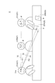
図2は、複数(ここでは3人)のユーザに対応付けられたユーザオブジェクト21(21A~21C)を含む仮想空間Vの一例を概略的に示した図である。以下、ユーザオブジェクト21Aの視線を制御する場合に着目して、上述した視線制御部14の処理について説明する。
図2の例は、3体のユーザオブジェクト21が同一の長机の前に座って会話をしている状況を示している。長机の上には、ユーザオブジェクト21とは異なる物体(ここでは、カード状の物体)を示す2つの物体オブジェクト22(22A,22B)が置かれている。ここでは一例として、ユーザオブジェクト21Aの視線方向(視軸)を示す仮視線31が、長机における物体オブジェクト22Aの手前の位置に向けられている。仮視線31の基点31aは、一例として、ユーザオブジェクト21Aの左右の両目の中間点に設定されている。また、各オブジェクト(ユーザオブジェクト21B,21C及び物体オブジェクト22A,22B)には、ユーザオブジェクト21Aの視線を向ける候補となる位置を示す候補点Pが設定されている。なお、1つのオブジェクトには、当該オブジェクトに設定された複数の部位(例えばユーザオブジェクト21の顔、胴体、腕等の身体部位)に対応する複数の候補点Pが設定されてもよい。本実施形態では、ユーザオブジェクト21には、当該ユーザオブジェクト21の顔に対応する部分に候補点Pが設定されている。物体オブジェクト22には、当該物体オブジェクト22の中心位置に候補点Pが設定されている。
この場合、例えば、視線制御部14は、仮視線31とユーザオブジェクト21(ここでは一例としてユーザオブジェクト21C)との距離を示す指標として、仮視線31の基点31aからユーザオブジェクト21の候補点Pに向けた仮想視線32と仮視線31とがなす角度θ1を算出する。例えば、視線制御部14は、仮想空間Vにおける水平方向において仮想視線32と仮視線31とがなす角度θ1h(すなわち、角度θ1の水平成分)と、仮想空間Vにおける垂直方向(鉛直方向)において仮想視線32と仮視線31とがなす角度θ1v(すなわち、角度θ1の垂直成分)とを算出し、角度θ1h及び角度θ1vに基づいて角度θ1を算出する。同様に、視線制御部14は、仮視線31と物体オブジェクト22(ここでは一例として物体オブジェクト22A)との距離を示す指標として、仮視線31の基点31aから物体オブジェクト22の候補点Pに向けた仮想視線33と仮視線31とがなす角度θ2を算出する。例えば、視線制御部14は、仮想空間Vにおける水平方向において仮想視線33と仮視線31とがなす角度θ2h(すなわち、角度θ2の水平成分)と、仮想空間Vにおける垂直方向(鉛直方向)において仮想視線33と仮視線31とがなす角度θ2v(すなわち、角度θ2の垂直成分)とを算出し、角度θ2h及び角度θ2vに基づいて角度θ2を算出する。
そして、視線制御部14は、これらの指標値(角度θ1,θ2)と所定の閾値Thとを比較する。そして、視線制御部14は、角度θ1,θ2が閾値Th以下となるオブジェクトを候補オブジェクトとして抽出する。図2の例において、「θ2<Th<θ1」が成立する場合、物体オブジェクト22Aは、候補オブジェクトとして抽出される一方で、ユーザオブジェクト21Cは、候補オブジェクトとして抽出されない。物体オブジェクト22Aが候補オブジェクトとして抽出された場合、視線制御部14は、物体オブジェクト22A(物体オブジェクト22Aの候補点P)を向くようにユーザオブジェクト21Aの視線を制御する。すなわち、視線制御部14は、ユーザオブジェクト21Aの視線を仮想視線33に一致させる。
視線制御部14は、上述のようにして抽出される候補オブジェクトが複数存在する場合、各候補オブジェクトの種別及び状態の少なくとも一方に基づいて、一の候補オブジェクトを選択し、当該一の候補オブジェクトを向くようにユーザオブジェクト21Aの視線を制御する。例えば、各オブジェクトには、オブジェクトの種別及び状態の少なくとも一方に基づく優先度が設定されている。視線制御部14は、候補オブジェクトが複数存在する場合、各候補オブジェクトに設定された優先度に基づいて、ユーザオブジェクト21Aの視線を向ける先となる候補オブジェクトを決定する。そして、視線制御部14は、ユーザオブジェクト21Aの視線を向ける先として決定された候補オブジェクトを向くようにユーザオブジェクト21Aの視線を制御し得る。
例えば、仮想空間V上で動いている物体オブジェクト22(以下「動くオブジェクト」ともいう。)には、仮想空間V上で動いていない物体オブジェクト22(以下「静止オブジェクト」ともいう。)よりも高い優先度が設定される。このような優先度の設定は、仮想空間V上において活性化しているオブジェクト(動くオブジェクト)は、静止オブジェクトよりもユーザから注目される可能性が高いという考え方に基づいている。
また、発話しているユーザに対応付けられたユーザオブジェクト21(以下「発話オブジェクト」ともいう。)には、発話していないユーザに対応付けられたユーザオブジェクト21(以下「非発話オブジェクト」ともいう。)よりも高い優先度が設定される。このような優先度の設定は、発話オブジェクトは、非発話オブジェクトよりもユーザから注目される可能性が高いという考え方に基づいている。
例えば、視線制御部14は、ユーザオブジェクト21に対応付けられたユーザがマイクに所定の大きさ以上の音量の音声を入力している状態(発話状態)であるか否かに基づいて、当該ユーザオブジェクト21が発話オブジェクトであるか否かを判定し得る。ここで、発話状態であるか否かは、例えば、所定の大きさ以上の音量の音声が前回入力されたときから所定時間(例えば、予め設定された秒数等)が経過したか否かに基づいて判定され得る。すなわち、視線制御部14は、所定の大きさ以上の音量の音声が前回入力されたときから所定時間が経過している場合には、発話状態でないと判定し、所定の大きさ以上の音量の音声が前回入力されたときから所定時間が経過していない場合には、発話状態であると判定する。ただし、発話状態であるか否かの判定方法は、上記方法に限定されない。例えば、発話しているユーザ(或いは、これから発話しようとするユーザ)は、図示しないコントローラ等の明示的な操作によって、自身のステータスを発話状態に切り替えてもよい。この場合、視線制御部14は、各ユーザに設定されているステータスに基づいて、発話状態であるか否かを判定できる。
本実施形態では一例として、以下の優先度順が設定されている。また、本実施形態では、視線制御部14は、非発話オブジェクトをユーザオブジェクト21Aの視線を向ける候補から除外する。ただし、視線制御部14は、非発話オブジェクトをユーザオブジェクト21Aの視線を向ける候補に含めてもよい。
1.動くオブジェクト
2.発話オブジェクト
3.静止オブジェクト
4.非発話オブジェクト
1.動くオブジェクト
2.発話オブジェクト
3.静止オブジェクト
4.非発話オブジェクト
視線制御部14は、優先度が高い候補オブジェクトがユーザオブジェクト21Aの視線を向ける先として優先的に選択されるように制御する。このような制御の一例(図4参照)については後述する。なお、同じ優先度が設定された複数の候補オブジェクト(すなわち、オブジェクトの種別及び状態が同一の候補オブジェクト同士)が存在する場合には、視線制御部14は、上述した指標値(角度θ1,θ2)が最小の候補オブジェクトを、ユーザオブジェクト21Aの視線を向ける先として選択してもよい。
また、視線制御部14は、ユーザオブジェクト21Aに対応付けられたユーザが発話中であるか否かを判定し、当該ユーザが発話中である場合には、発話中のユーザに対応付けられたユーザオブジェクト(すなわち、発話オブジェクト)について予め定められた制御内容に基づいて、ユーザオブジェクト21Aの視線を制御してもよい。例えば、ユーザオブジェクト21Aの視線は、発話者(例えば発表者等)として適切なふるまいとなるように、予め設定された特別な制御内容に基づいて制御されてもよい。例えば、ユーザオブジェクト21Aの仮視線31が一定範囲内に固定されている場合(例えば、仮視線31の単位時間当たりの変化量が予め定められた閾値以内である場合)には、視線制御部14は、ユーザオブジェクト21Aの仮視線31をそのままユーザオブジェクト21Aの制御後の視線として採用してもよい。一方、ユーザオブジェクト21Aの仮視線31が一定範囲内を超えて変化する場合(例えば、仮視線31の単位時間当たりの変化量が上記閾値を超える場合(仮視線31が大きくふらつく場合))には、視線制御部14は、各ユーザオブジェクト21B,21Cに対して順に視線を送るように、ユーザオブジェクト21Aの視線を制御してもよい。
画像生成部15は、視線制御部14により制御されたユーザオブジェクト21Aの視線が反映された画像(各HMD1に表示される画像)を生成する。例えば、画像生成部15は、視線制御部14により制御されたユーザオブジェクト21Aの視線(視線方向及び/又は視点)と各HMD1に画像に表示されるユーザオブジェクト21Aの顔の向き及び目(黒目の位置)等により特定される視線(視線方向及び/又は視点)とが一致するように調整された画像を生成する。画像生成部15により生成された画像は、通信部11を介して各HMD1に出力される。このような処理により、視線制御部14によって制御されたユーザオブジェクト21Aの視線が反映された画像が、各HMD1を介して各ユーザに提示される。
次に、図3~図6を参照して、情報処理装置10の動作の一例について説明する。なお、図3及び図4に示すフローチャートは、図2に示されるユーザオブジェクト21Aの視線制御を行う場合に着目した処理を示している。他のユーザに対応付けられたユーザオブジェクト21B,21Cの視線制御については、ユーザオブジェクト21Aの視線制御と同様であるため、説明を省略する。
図3に示されるように、まず、情報処理装置10が、複数のユーザによって共有される仮想空間V(図2参照)を生成する(ステップS1)。具体的には、各ユーザに対応付けられたユーザオブジェクト21及び物体オブジェクト22等が初期位置に配置された仮想空間Vが生成される。続いて、動作情報取得部12は、通信部11を介して、各HMD1から受信された各ユーザの頭部及び目の動作情報を取得する(ステップS2)。続いて、仮視線決定部13は、動作情報取得部12により取得されたユーザの動作情報に基づいて、当該ユーザに対応付けられたユーザオブジェクト21(ここでは、ユーザオブジェクト21A)の仮視線31を決定する。続いて、視線制御部14は、仮視線決定部13により決定されたユーザオブジェクト21Aの仮視線31と仮想空間V上の一以上のオブジェクト(他のユーザオブジェクト21及び物体オブジェクト22)との位置関係に基づいて、ユーザオブジェクト21Aの視線を制御する(ステップS4)。
図4を参照して、ステップS4の詳細な処理手順の一例について説明する。図4に示される処理手順は、上述した優先度順に従ってユーザオブジェクト21Aの視線を向ける先となる候補オブジェクトを選択するような判定手順の一例である。
図4に示されるように、まず、視線制御部14は、処理対象となるユーザオブジェクト21Aに対応付けられたユーザが発話中であるか否かを判定する(ステップS41)。ユーザが発話中である場合(ステップS41:YES)、視線制御部14は、上述したような予め定められた制御内容に基づいて、ユーザオブジェクト21Aの視線を制御する(ステップS42)。例えば、ユーザオブジェクト21Aの仮視線31が一定範囲内に固定されている場合には、視線制御部14は、ユーザオブジェクト21Aの仮視線31をそのままユーザオブジェクト21Aの制御後の視線として採用する。一方、ユーザオブジェクト21Aの仮視線31が一定範囲内を超えて変化する場合(ふらつく場合)には、視線制御部14は、各ユーザオブジェクト21B,21Cに対して順に視線を送るように、ユーザオブジェクト21Aの視線を制御する。このような処理により、ユーザオブジェクト21Aの視線は、発話者として適切なふるまいとなるように制御される。
一方、ユーザが発話中ではない場合(ステップS41:NO)、視線制御部14は、仮視線31と仮想視線33(基点31aと物体オブジェクト22の候補点Pとを結ぶ線分)とがなす角度θ2が閾値Th以下となる動くオブジェクトが存在するか否かを判定する(ステップS43)。上記判定条件を満たす動くオブジェクト(候補オブジェクト)が存在する場合(ステップS43:YES)、視線制御部14は、上記判定条件を満たす動くオブジェクト(上記判定条件を満たす動くオブジェクトが複数存在する場合には、角度θ2が最小の動くオブジェクト)の候補点Pに、ユーザオブジェクト21の視線を向ける。すなわち、視線制御部14は、ユーザオブジェクト21の視線を、基点31aと当該動くオブジェクトの候補点Pとを結ぶ仮想視線33に一致させる。
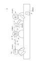
図5は、物体オブジェクト22Aがユーザオブジェクト21Cによって保持され、ユーザオブジェクト21Cの手が動かされることにより物体オブジェクト22Aが動いている状態を示している。この場合、物体オブジェクト22Aは、動くオブジェクトであると判定される。この例において、仮視線31と仮想視線33(基点31aと物体オブジェクト22Aの候補点Pとを結ぶ線分)とがなす角度θ2が閾値Th以下である場合には、物体オブジェクト22Aは、ステップS43の判定条件を満たす。その場合、視線制御部14は、ユーザオブジェクト21の視線を上記仮想視線33に一致させる。
一方、「θ2≦Th」を満たす動くオブジェクトが存在しない場合(ステップS43:NO)、視線制御部14は、仮視線31と仮想視線32(基点31aとユーザオブジェクト21の候補点Pとを結ぶ線分)とがなす角度θ1が閾値Th以下となる発話オブジェクトが存在するか否かを判定する(ステップS45)。上記判定条件を満たす発話オブジェクト(候補オブジェクト)が存在する場合(ステップS45:YES)、視線制御部14は、上記判定条件を満たす発話オブジェクト(上記判定条件を満たす発話オブジェクトが複数存在する場合には、角度θ1が最小の発話オブジェクト)の候補点Pに、ユーザオブジェクト21の視線を向ける。すなわち、視線制御部14は、ユーザオブジェクト21の視線を、基点31aと当該発話オブジェクトの候補点Pとを結ぶ仮想視線32に一致させる。
図6は、ユーザオブジェクト21Bが非発話オブジェクトである一方で、ユーザオブジェクト21Cが発話オブジェクトである状態を示している。この例において、仮視線31と仮想視線32(基点31aとユーザオブジェクト21Cの候補点Pとを結ぶ線分)とがなす角度θ1が閾値Th以下である場合には、ユーザオブジェクト21Cは、ステップS45の判定条件を満たす。したがって、この場合には、視線制御部14は、ユーザオブジェクト21の視線を上記仮想視線32に一致させる。
一方、「θ1≦Th」を満たす発話オブジェクトが存在しない場合(ステップS45:NO)、視線制御部14は、仮視線31と仮想視線33(基点31aと物体オブジェクト22の候補点Pとを結ぶ線分)とがなす角度θ2が閾値Th以下となる静止オブジェクトが存在するか否かを判定する(ステップS47)。上記判定条件を満たす静止オブジェクトが存在する場合(ステップS47:YES)、視線制御部14は、上記判定条件を満たす静止オブジェクト(上記判定条件を満たす静止オブジェクトが複数存在する場合には、角度θ2が最小の静止オブジェクト)の候補点Pに、ユーザオブジェクト21の視線を向ける。
上述した図2において、物体オブジェクト22Aは、静止オブジェクトである。この例において、仮視線31と仮想視線33(基点31aと物体オブジェクト22Aの候補点Pとを結ぶ線分)とがなす角度θ2が閾値Th以下である場合には、物体オブジェクト22Aは、ステップS47の判定条件を満たす。したがって、この場合には、視線制御部14は、ユーザオブジェクト21の視線を上記仮想視線33に一致させる。なお、図2の例では、基点31aと物体オブジェクト22Bの候補点Pとを結ぶ線分と仮視線31とがなす角度(以下「角度A」という。)も閾値Th以下となる可能性がある。ただし、この場合にも、角度θ2の方が角度Aよりも小さいため、視線制御部14は、物体オブジェクト22Aを、ユーザオブジェクト21の視線を向ける先として選択する。
一方、「θ2≦Th」を満たす静止オブジェクトが存在しない場合(ステップS47:NO)、視線制御部14は、仮視線31をユーザオブジェクト21Aの視線とする(ステップS49)。すなわち、視線制御部14は、ユーザオブジェクト21Aの視線を仮視線31に一致させる。
続いて、図3に戻り、画像生成部15は、視線制御部14により制御されたユーザオブジェクト21Aの視線が反映された画像(各HMD1に表示される画像)を生成する(ステップS5)。画像生成部15により生成された各ユーザ用の画像(すなわち、各ユーザに対応付けられたユーザオブジェクト21の視界に応じた画像)は、例えば、通信部11を介して各HMD1に送信され、各HMD1において表示される。これにより、各ユーザは、HMD1に表示された画像を通じて、視線制御部14により制御されたユーザオブジェクト21Aの視線を認識する。
以上述べた情報処理装置10によれば、実際に検出されたユーザの頭部及び目の動作情報に基づいて、一旦ユーザオブジェクト21Aの仮視線31が決定される。そして、仮視線31と仮想空間V上の一以上のオブジェクト(本実施形態では、他のユーザオブジェクト21及び物体オブジェクト22)との位置関係に基づいて、ユーザオブジェクト21Aの視線が制御され、HMD1に表示される画像が生成される。このような処理によれば、実際に検出されたユーザの視線(動作情報)をそのままユーザオブジェクト21Aの視線に適用する場合と比較して、より自然な方向を向くように制御されたユーザオブジェクト21Aの視線をユーザ(本実施形態では、各ユーザオブジェクト21A~21Cに対応付けられた各ユーザ)に提示できる。その結果、ユーザオブジェクト21Aを介した仮想空間V上のユーザ間のコミュニケーションをより一層円滑化できる。
また、視線制御部14は、仮視線31とオブジェクトとの距離を示す指標値(本実施形態では角度θ1,θ2)を算出し、指標値と所定の閾値Thとを比較し、指標値が閾値Th以下となるオブジェクトである候補オブジェクトが存在する場合、当該候補オブジェクトを向くようにユーザオブジェクト21の視線を制御する。上記構成により、仮視線31とオブジェクトとの距離が所定の基準よりも近い候補オブジェクトを向くようにユーザオブジェクト21の視線が制御される。この処理により、ユーザオブジェクト21に対応付けられたユーザが注目している可能性が高いと推定されるオブジェクト(候補オブジェクト)を向くように、ユーザオブジェクト21Aの視線を固定することができる。このため、実際に検出されたユーザの視線(動作情報)をそのままユーザオブジェクト21の視線に適用する場合に生じ得るユーザオブジェクト21の視線のずれ(ユーザの頭部又は目の動作の検出誤差に基づくずれ)及びユーザオブジェクト21の視線のふらつき等を抑制できる。その結果、画像生成部15により生成される画像(映像)において、より自然且つスムーズなユーザオブジェクト21の視線を表現でき、ユーザオブジェクト21を介したユーザ間のコミュニケーションの円滑化を図ることができる。
補足すると、ユーザがあるオブジェクト(例えば発話オブジェクト)の方向を見ている場合において、HMD1に搭載されたセンサ等によって検出された当該ユーザの頭部又は目の動作情報に検出誤差が生じ得る。この場合、上記動作情報に基づく視線(すなわち、仮視線31)を当該ユーザに対応付けられたユーザオブジェクト21の視線としてそのまま適用してしまうと、上記検出誤差がそのままユーザオブジェクト21の視線にも影響を与えることとなる。すなわち、上記検出誤差の分だけユーザオブジェクト21の視線に誤差が生じることにより、ユーザオブジェクト21の視線が上記発話オブジェクトを向く方向からずれてしまう。一方、情報処理装置10(特に視線制御部14)の処理によれば、このような検出誤差を吸収し、ユーザオブジェクト21の視線を、ユーザが注目している可能性が高いと考えられるオブジェクト(この例では、上記発話オブジェクト)を向くように制御することが可能となる。
また、あるユーザ(第1ユーザ)に対してHMD1を介して提供される視界画像に他のユーザ(第2ユーザ)に対応付けられたユーザオブジェクト21を表示させるためには、当該視界画像を生成する情報処理装置10は、第2ユーザの動作情報を受信し、当該動作情報に基づいて第2ユーザに対応付けられたユーザオブジェクト21の動作を制御する必要がある。ここで、第2ユーザの動作情報の受信又は制御についての遅延(通信遅延、処理遅延等)が生じた場合、実際の第2ユーザの動作と当該第2ユーザに対応付けられたユーザオブジェクト21の動作との間に時間差が生じるおそれがある。また、遅延によって処理の一部が省略されることにより、当該ユーザオブジェクト21の顔の向き及び目線等が不連続に変化する(突然大きく変化する)といった違和感のある映像が第1ユーザに提供されるおそれもある。一方、情報処理装置10(視線制御部14)の処理によれば、実際のユーザの視線(すなわち、仮視線31)が若干ふらつく場合であっても、ユーザオブジェクト21の視線を、候補オブジェクトを向く方向に固定することができる。このような処理により、ユーザオブジェクト21の視線のふらつきを抑制し、相手ユーザに不安感を与えてしまうことを抑制できる。その結果、ユーザ間のコミュニケーションの円滑化を図ることができる。さらに、情報処理装置10の上述した制御によれば、第2ユーザの頭部又は目の動作と当該第2ユーザに対応付けられたユーザオブジェクト21の動作(視線)とを完全に連動させる必要がない。つまり、情報処理装置10の制御によれば、第2ユーザの視線(仮視線31)が候補オブジェクトから大きく外れてしまわない限り、ユーザオブジェクト21の視線を候補オブジェクトを向く方向に固定することができる。この間、第2ユーザの頭部又は目の実際の動作をユーザオブジェクト21の動作(視線)に反映させる必要がない。これにより、プロセッサ、メモリ等のハードウェア資源の処理負荷及び使用量を効果的に低減できる。
なお、本実施形態では、仮視線31と仮想視線32,33とがなす角度θ1,θ2が指標値として用いられたが、指標値はこれ以外の値であってもよい。例えば、視線制御部14は、角度θ1の代わりに、角度θ1の水平成分(角度θ1h)又は垂直成分(角度θ1v)のみを用いて上記の判定を行ってもよい。すなわち、視線制御部14は、上述した角度θ1と閾値Thとを比較する代わりに、角度θ1の水平成分(角度θ1h)又は垂直成分(角度θ1v)と所定の閾値とを比較することにより、候補オブジェクトを抽出してもよい。同様に、視線制御部14は、角度θ2の代わりに、角度θ2の水平成分(角度θ2h)又は垂直成分(角度θ2v)のみを用いて上記の判定を行ってもよい。すなわち、視線制御部14は、上述した角度θ2と閾値Thとを比較する代わりに、角度θ2の水平成分(角度θ2h)又は垂直成分(角度θ2v)と所定の閾値とを比較することにより、候補オブジェクトを抽出してもよい。また、仮視線決定部13が、上述したユーザの頭部及び目の動作情報に基づいて、ユーザの視線方向だけでなく視点(注視点)も含む仮視線を決定する場合には、当該視点とオブジェクト(オブジェクトに設定された候補点P)との距離(例えば、仮想空間V上における直線距離)が指標値として用いられてもよい。
また、視線制御部14は、候補オブジェクトが複数存在する場合、各候補オブジェクトの種別及び状態の少なくとも一方に基づいて、一の候補オブジェクトを選択し、当該一の候補オブジェクトを向くようにユーザオブジェクト21の視線を制御する。上記構成により、候補オブジェクトが複数存在する場合に、候補オブジェクトの種別及び状態の少なくとも一方に基づいて、ユーザオブジェクト21の視線を向ける先となる候補オブジェクトを適切に決定することができる。
また、動くオブジェクト(仮想空間V上で動いている物体を示す物体オブジェクト22)には、静止オブジェクト(仮想空間V上で動いていない物体を示す物体オブジェクト22)よりも高い優先度が設定されており、視線制御部14は、候補オブジェクトが複数存在する場合、優先度に基づいてユーザオブジェクト21の視線を向ける先となる候補オブジェクトを決定し、決定された候補オブジェクトを向くようにユーザオブジェクト21の視線を制御する。上記構成によれば、動くオブジェクトは静止オブジェクトよりもユーザの目を惹く可能性が高いという本発明者の知見に基づき、ユーザが注目している可能性が高いオブジェクトを向くように、ユーザオブジェクト21の視線を制御することができる。なお、同じ優先度が設定された複数の候補オブジェクト(すなわち、オブジェクトの種別及び状態が同一の候補オブジェクト同士)が存在する場合には、例えば、視線制御部14は、これらの複数の候補オブジェクトのうち上述した指標値(角度θ1,θ2)が最小の候補オブジェクトを、ユーザオブジェクト21の視線を向ける先として選択してもよい。上記処理によっても一の候補オブジェクトが決定されない場合には、視線制御部14は、例えば比較処理が行われた順序等の任意の指標に基づいて一の候補オブジェクトを決定してもよい。このような処理により、ユーザオブジェクト21の視線を向ける先となる候補オブジェクトを適切に決定することができる。
また、発話オブジェクト(発話しているユーザに対応付けられたユーザオブジェクト21)には、非発話オブジェクト(発話していないユーザに対応付けられたユーザオブジェクト21)よりも高い優先度が設定されている。上記構成によれば、発話オブジェクトは非発話オブジェクトよりもユーザの目を惹く可能性が高いという本発明者の知見に基づき、ユーザが注目している可能性が高いオブジェクトを向くように、ユーザオブジェクト21の視線を制御することができる。
なお、上記実施形態の説明に用いたブロック図(図1)は、機能単位のブロックを示している。これらの機能ブロック(構成部)は、ハードウェア及び/又はソフトウェアの任意の組み合わせによって実現される。また、各機能ブロックの実現手段は特に限定されない。すなわち、各機能ブロックは、物理的及び/又は論理的に結合した1つの装置により実現されてもよいし、物理的及び/又は論理的に分離した2つ以上の装置を直接的及び/又は間接的に(例えば、有線及び/又は無線で)接続し、これら複数の装置により実現されてもよい。
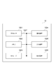
例えば、上記実施形態における情報処理装置10は、上記実施形態の情報処理装置10の処理を行うコンピュータとして機能してもよい。図9は、本実施形態に係る情報処理装置10のハードウェア構成の一例を示す図である。上述の情報処理装置10は、物理的には、プロセッサ1001、メモリ1002、ストレージ1003、通信装置1004、入力装置1005、出力装置1006、及びバス1007等を含むコンピュータ装置として構成されてもよい。
なお、以下の説明では、「装置」という文言は、回路、デバイス、ユニット等に読み替えることができる。情報処理装置10のハードウェア構成は、図9に示された各装置を1つ又は複数含むように構成されてもよいし、一部の装置を含まずに構成されてもよい。
情報処理装置10における各機能は、プロセッサ1001、メモリ1002等のハードウェア上に所定のソフトウェア(プログラム)を読み込ませることで、プロセッサ1001が演算を行い、通信装置1004による通信、メモリ1002及びストレージ1003におけるデータの読み出し及び/又は書き込みを制御することで実現される。
プロセッサ1001は、例えば、オペレーティングシステムを動作させてコンピュータ全体を制御する。プロセッサ1001は、周辺装置とのインターフェース、制御装置、演算装置、レジスタ等を含む中央処理装置(CPU:Central Processing Unit)で構成されてもよい。
また、プロセッサ1001は、プログラム(プログラムコード)、ソフトウェアモジュール、及び/又はデータを、ストレージ1003及び/又は通信装置1004からメモリ1002に読み出し、これらに従って各種の処理を実行する。プログラムとしては、上述の実施の形態で説明した動作の少なくとも一部をコンピュータに実行させるプログラムが用いられる。例えば、情報処理装置10の視線制御部14は、メモリ1002に格納され、プロセッサ1001で動作する制御プログラムによって実現されてもよく、図1に示した他の機能ブロックについても同様に実現されてもよい。上述の各種処理は、1つのプロセッサ1001で実行される旨を説明してきたが、2以上のプロセッサ1001により同時又は逐次に実行されてもよい。プロセッサ1001は、1以上のチップで実装されてもよい。なお、プログラムは、電気通信回線を介してネットワークから送信されてもよい。
メモリ1002は、コンピュータ読み取り可能な記録媒体であり、例えば、ROM(Read Only Memory)、EPROM(Erasable Programmable ROM)、EEPROM(Electrically Erasable Programmable ROM)、RAM(Random Access Memory)等の少なくとも1つで構成されてもよい。メモリ1002は、レジスタ、キャッシュ、メインメモリ(主記憶装置)等と呼ばれてもよい。メモリ1002は、上記実施形態に係る情報処理方法(例えば図3及び図4のフローチャートに示される手順等)を実施するために実行可能なプログラム(プログラムコード)、ソフトウェアモジュール等を保存することができる。
ストレージ1003は、コンピュータ読み取り可能な記録媒体であり、例えば、CD-ROM(Compact Disc ROM)等の光ディスク、ハードディスクドライブ、フレキシブルディスク、光磁気ディスク(例えば、コンパクトディスク、デジタル多用途ディスク、Blu-ray(登録商標)ディスク)、スマートカード、フラッシュメモリ(例えば、カード、スティック、キードライブ)、フロッピー(登録商標)ディスク、磁気ストリップ等の少なくとも1つで構成されてもよい。ストレージ1003は、補助記憶装置と呼ばれてもよい。上述の記憶媒体は、例えば、メモリ1002及び/又はストレージ1003を含むデータベース、サーバ、その他の適切な媒体であってもよい。
通信装置1004は、有線及び/又は無線ネットワークを介してコンピュータ間の通信を行うためのハードウェア(送受信デバイス)であり、例えばネットワークデバイス、ネットワークコントローラ、ネットワークカード、通信モジュール等ともいう。
入力装置1005は、外部からの入力を受け付ける入力デバイス(例えば、キーボード、マウス、マイクロフォン、スイッチ、ボタン、センサ等)である。出力装置1006は、外部への出力を実施する出力デバイス(例えば、ディスプレイ、スピーカー、LEDランプ等)である。なお、入力装置1005及び出力装置1006は、一体となった構成(例えば、タッチパネル)であってもよい。
また、プロセッサ1001及びメモリ1002等の各装置は、情報を通信するためのバス1007で接続される。バス1007は、単一のバスで構成されてもよいし、装置間で異なるバスで構成されてもよい。
また、情報処理装置10は、マイクロプロセッサ、デジタル信号プロセッサ(DSP:Digital Signal Processor)、ASIC(Application Specific Integrated Circuit)、PLD(Programmable Logic Device)、FPGA(Field Programmable Gate Array)等のハードウェアを含んで構成されてもよく、当該ハードウェアにより、各機能ブロックの一部又は全てが実現されてもよい。例えば、プロセッサ1001は、これらのハードウェアの少なくとも1つで実装されてもよい。
以上、本発明について詳細に説明したが、当業者にとっては、本発明が本明細書中に説明した実施形態に限定されるものではないということは明らかである。本発明は、特許請求の範囲の記載により定まる本発明の趣旨及び範囲を逸脱することなく修正及び変更された態様として実施することができる。したがって、本明細書の記載は、例示説明を目的とするものであり、本発明に対して何ら制限的な意味を有するものではない。
[変形例1]
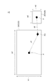
例えば、視線制御部14は、オブジェクトの大きさに基づいて指標値又は閾値を調整してもよい。図7は、仮想空間Vにおいて、幅がw1、高さがh1の矩形状の物体オブジェクト22Cと、幅がw2(<w1)、高さがh2(<h1)の矩形状の物体オブジェクト22Dとが互いに隣接している状態を示している。なお、図7は、視線制御の対象となるユーザオブジェクト21から見た仮想空間Vの画像(視界)を概略的に示している。ここで、物体オブジェクト22C,22Dには、それぞれの中心点に候補点Pが設定されている。また、この例では、上記ユーザオブジェクト21の仮視線31は視点(注視点)P0を示す情報を含んでおり、視線制御部14は、視点P0と各オブジェクトの候補点Pとの距離d1,d2を上記実施形態で説明した指標値として使用する。
例えば、視線制御部14は、オブジェクトの大きさに基づいて指標値又は閾値を調整してもよい。図7は、仮想空間Vにおいて、幅がw1、高さがh1の矩形状の物体オブジェクト22Cと、幅がw2(<w1)、高さがh2(<h1)の矩形状の物体オブジェクト22Dとが互いに隣接している状態を示している。なお、図7は、視線制御の対象となるユーザオブジェクト21から見た仮想空間Vの画像(視界)を概略的に示している。ここで、物体オブジェクト22C,22Dには、それぞれの中心点に候補点Pが設定されている。また、この例では、上記ユーザオブジェクト21の仮視線31は視点(注視点)P0を示す情報を含んでおり、視線制御部14は、視点P0と各オブジェクトの候補点Pとの距離d1,d2を上記実施形態で説明した指標値として使用する。
視点P0と物体オブジェクト22Cの候補点Pとの距離d1、及び視点P0と物体オブジェクト22Dの候補点Pとの距離d2について、「d1>Th」と「d2<Th」とが成立する場合、物体オブジェクト22Dが、ユーザオブジェクト21の視線を向ける先の候補オブジェクトとして決定される。また、「d1<Th」と「d2<Th」とが成立する場合にも、「d1>d2」であるため、物体オブジェクト22Dがユーザオブジェクト21の視線を向ける先の候補オブジェクトとして決定される。しかし、図7に示されるように、ユーザオブジェクト21の視点P0は実際には物体オブジェクト22Cの縁部に位置している。すなわち、ユーザオブジェクト21に対応するユーザは、物体オブジェクト22Dではなく、物体オブジェクト22Cを見ている可能性が高い。
そこで、このような場合に物体オブジェクト22Cがユーザオブジェクト21の視線を向ける先の候補オブジェクトとして適切に決定されるように、例えば、視線制御部14は、指標値となるd1,d2を以下のように調整してもよい。すなわち、視線制御部14は、例えば下記(式1)及び(式2)により、物体オブジェクト22C,22Dの大きさ(ここでは、物体オブジェクト22C,22Dの半径(対角線の長さの半分))に基づいて、以下のように調整された指標値d1new,d2newを算出する。
d1new=d1-√(w12+h12)/2 …(式1)
d2new=d2-√(w22+h22)/2 …(式2)
d1new=d1-√(w12+h12)/2 …(式1)
d2new=d2-√(w22+h22)/2 …(式2)
このように調整された指標値d1newを用いることにより、「d1new<Th」が成立する可能性が高くなる。また、物体オブジェクト22Cの上記半径「√(w12+h12)/2」は、物体オブジェクト22Dの上記半径「√(w22+h22)/2」よりも大きく、「d1new<d2new」が成立する。したがって、「d1new<Th」と「d2new<Th」とが成立する場合であっても、物体オブジェクト22Cが物体オブジェクト22Dよりも優先的に、ユーザオブジェクト21の視線を向ける先の候補オブジェクトとして決定される。
なお、上記例において、指標値d1,d2ではなく、物体オブジェクト22C,22Dに対して個別に閾値を調整してもよい。例えば、視線制御部14は、物体オブジェクト22Cの指標値d1との比較を、閾値Thではなく下記(式3)により算出される閾値Th1を用いて行ってもよい。同様に、視線制御部14は、物体オブジェクト22Dの指標値d2との比較を、閾値Thではなく下記(式4)により算出される閾値Th2を用いて行ってもよい。
Th1=Th+√(w12+h12)/2 …(式3)
Th2=Th+√(w22+h22)/2 …(式4)
Th1=Th+√(w12+h12)/2 …(式3)
Th2=Th+√(w22+h22)/2 …(式4)
このように調整された閾値Th1,Th2を用いることにより、物体オブジェクト22のサイズ(ここでは上記半径)が大きい程、判定条件が緩和されることになる。すなわち、物体オブジェクト22のサイズが大きい程、候補オブジェクトとして抽出されるための条件(「d1≦Th1」又は「d2≦Th2」)を満たす可能性が高くなる。なお、「d1≦Th1」及び「d2≦Th2」の両方が成立する場合、視線制御部14は、例えば「d1-Th1」と「d2-Th2」とを比較することにより、ユーザオブジェクト21の視線を向ける先の候補オブジェクトを決定してもよい。具体的には、視線制御部14は、「d1-Th1<d2-Th2」である場合には、物体オブジェクト22Cをユーザオブジェクト21の視線を向ける先の候補オブジェクトとして決定し、「d1-Th1>d2-Th2」である場合には、物体オブジェクト22Dをユーザオブジェクト21の視線を向ける先の候補オブジェクトとして決定すればよい。このようにすれば、上述した指標値d1new,d2newを用いる場合と同様の制御結果が得られる。
変形例1によれば、オブジェクト(ここでは物体オブジェクト22)の大きさを考慮して指標値(ここでは、d1,d2)又は閾値Thを調整し、調整後の指標値又は閾値に基づいて候補オブジェクトの判定を行うことができる。その結果、より適切なオブジェクト(候補点P)を向くように、ユーザオブジェクト21の視線を制御することが可能となる。
なお、上述したような指標値又は閾値の調整を行う代わりに、予め各オブジェクト(物体オブジェクト22)に対して、当該オブジェクトの大きさに応じた数の候補点Pが設定されてもよい。例えば、候補点Pを一定間隔毎に設定した場合、物体オブジェクト22のサイズが大きい程、多くの候補点Pが設定されることになる。その結果、図7の例のように物体オブジェクト22の中心点にのみ候補点Pが設定される場合の上述したような問題を回避できる。ただし、視線制御部14の処理において、候補点P毎に比較が必要となるため、候補点の数を増やした場合には、比較回数が増大する。一方、上述したような指標値又は閾値の調整を行った場合には、候補点Pの数をなるべく少なくして視線制御部14の処理量を抑制しつつ、候補オブジェクトを適切に決定できる。
[変形例2]
また、視線制御部14は、ユーザオブジェクト21の視線を向ける先として決定された候補オブジェクトが動くオブジェクトである場合、当該候補オブジェクトの移動態様に基づいて、ユーザオブジェクト21の視線を当該候補オブジェクトに向けるか否かを決定してもよい。例えば、動くオブジェクトである候補オブジェクトが、単位時間当たりに一定の距離以上移動する移動態様である場合(例えば、所定の閾値距離を所定の閾値速度以上で移動する場合)、ユーザの動作情報から得られた視線(仮視線31)と調整後の視線(当該候補オブジェクトを向く視線)とが瞬間的に大きく乖離してしまうことになる。また、極めて高速に移動するオブジェクトの動きに実際のユーザの視線が完全に追従することは、ほとんどない(又は不可能である)。
また、視線制御部14は、ユーザオブジェクト21の視線を向ける先として決定された候補オブジェクトが動くオブジェクトである場合、当該候補オブジェクトの移動態様に基づいて、ユーザオブジェクト21の視線を当該候補オブジェクトに向けるか否かを決定してもよい。例えば、動くオブジェクトである候補オブジェクトが、単位時間当たりに一定の距離以上移動する移動態様である場合(例えば、所定の閾値距離を所定の閾値速度以上で移動する場合)、ユーザの動作情報から得られた視線(仮視線31)と調整後の視線(当該候補オブジェクトを向く視線)とが瞬間的に大きく乖離してしまうことになる。また、極めて高速に移動するオブジェクトの動きに実際のユーザの視線が完全に追従することは、ほとんどない(又は不可能である)。
そこで、視線制御部14は、候補オブジェクトの移動態様が上記のような条件を満たす場合には、ユーザオブジェクト21の視線を当該候補オブジェクトに向けないようにしてもよい。すなわち、視線制御部14は、ユーザオブジェクト21の視線を当該候補オブジェクトに追従させないようにしてもよい。この場合、視線制御部14は、例えば過去所定期間における当該候補オブジェクトの位置から、直近の候補オブジェクトの移動範囲を導出し、当該移動範囲の中心点にユーザオブジェクト21の視点を固定してもよい。
変形例2によれば、候補オブジェクトの移動態様に基づいて、ユーザオブジェクト21の視線が不自然な視線(上記例では、高速移動している候補オブジェクトに完全追従するような視線)となることを抑制することができる。
[変形例3]
また、視線制御部14は、仮視線31に基づいて仮想空間Vの一部を構成する範囲を決定し、当該範囲に含まれるオブジェクトを抽出し、仮視線31と抽出されたオブジェクトとの位置関係に基づいて、ユーザオブジェクト21の視線を制御してもよい。図8は、仮視線31に基づいて決定されるオブジェクトの抽出範囲の一例を示している。図8の例では、視線制御部14は、仮視線31の視点P0から半径rの球状領域を、上述した範囲Rとして決定している。この例では、当該範囲Rに含まれるユーザオブジェクト21C及び物体オブジェクト22E,22F,22G(これらの候補点P)が、ユーザオブジェクト21の視線を向ける先の候補として抽出される。そして、これ以外のオブジェクトについては、ユーザオブジェクト21の視線を向ける先の候補から除外され、上述した閾値の比較等の処理は行われない。
また、視線制御部14は、仮視線31に基づいて仮想空間Vの一部を構成する範囲を決定し、当該範囲に含まれるオブジェクトを抽出し、仮視線31と抽出されたオブジェクトとの位置関係に基づいて、ユーザオブジェクト21の視線を制御してもよい。図8は、仮視線31に基づいて決定されるオブジェクトの抽出範囲の一例を示している。図8の例では、視線制御部14は、仮視線31の視点P0から半径rの球状領域を、上述した範囲Rとして決定している。この例では、当該範囲Rに含まれるユーザオブジェクト21C及び物体オブジェクト22E,22F,22G(これらの候補点P)が、ユーザオブジェクト21の視線を向ける先の候補として抽出される。そして、これ以外のオブジェクトについては、ユーザオブジェクト21の視線を向ける先の候補から除外され、上述した閾値の比較等の処理は行われない。
変形例3によれば、仮想空間V上に複数のオブジェクトが存在する場合に、計算対象となるオブジェクト(ユーザオブジェクト21の視線を向ける先の候補)を絞り込むことにより、視線制御部14の計算量を抑制することができる。その結果、処理の高速化、使用メモリ量の削減等を図ることができる。なお、上述した範囲Rは一例であり、例えば、仮視線31の視点P0の先に発話オブジェクトが存在する場合には、当該発話オブジェクトの候補点Pを中心とする半径rの球状領域等が、上述した範囲Rの代わりに用いられてもよい。
本明細書で説明した各態様/実施形態の処理手順、シーケンス、フローチャート等は、矛盾の無い限り、順序を入れ替えてもよい。例えば、本明細書で説明した方法については、例示的な順序で様々なステップの要素を提示しており、提示した特定の順序に限定されない。
入出力された情報等は特定の場所(例えば、メモリ)に保存されてもよいし、管理テーブルで管理されてもよい。入出力される情報等は、上書き、更新、又は追記され得る。出力された情報等は削除されてもよい。入力された情報等は他の装置へ送信されてもよい。
判定は、1ビットで表される値(0か1か)によって行われてもよいし、真偽値(Boolean:true又はfalse)によって行われてもよいし、数値の比較(例えば、所定の値との比較)によって行われてもよい。
本明細書で説明した各態様/実施形態は単独で用いられてもよいし、組み合わせて用いられてもよいし、実行に伴って切り替えて用いられてもよい。
ソフトウェアは、ソフトウェア、ファームウェア、ミドルウェア、マイクロコード、ハードウェア記述言語と呼ばれるか、他の名称で呼ばれるかを問わず、命令、命令セット、コード、コードセグメント、プログラムコード、プログラム、サブプログラム、ソフトウェアモジュール、アプリケーション、ソフトウェアアプリケーション、ソフトウェアパッケージ、ルーチン、サブルーチン、オブジェクト、実行可能ファイル、実行スレッド、手順、機能等を意味するよう広く解釈されるべきである。
また、ソフトウェア、命令等は、伝送媒体を介して送受信されてもよい。例えば、ソフトウェアが、同軸ケーブル、光ファイバケーブル、ツイストペア及びデジタル加入者回線(DSL)等の有線技術及び/又は赤外線、無線及びマイクロ波等の無線技術を使用してウェブサイト、サーバ、又は他のリモートソースから送信される場合、これらの有線技術及び/又は無線技術は、伝送媒体の定義内に含まれる。
本明細書で説明した情報及び信号等は、様々な異なる技術のいずれかを使用して表されてもよい。例えば、上記の説明全体に渡って言及され得るデータ、命令、コマンド、情報、信号、ビット、シンボル、チップ等は、電圧、電流、電磁波、磁界若しくは磁性粒子、光場若しくは光子、又はこれらの任意の組み合わせによって表されてもよい。
なお、本明細書で説明した用語及び/又は本明細書の理解に必要な用語については、同一の又は類似する意味を有する用語と置き換えてもよい。
また、本明細書で説明した情報、パラメータ等は、絶対値で表されてもよいし、所定の値からの相対値で表されてもよいし、対応する別の情報で表されてもよい。
上述したパラメータに使用される名称はいかなる点においても限定的なものではない。さらに、これらのパラメータを使用する数式等は、本明細書で明示的に開示したものと異なる場合もある。
本明細書で使用する「に基づいて」という記載は、別段に明記されていない限り、「のみに基づいて」を意味しない。言い換えれば、「に基づいて」という記載は、「のみに基づいて」と「に少なくとも基づいて」との両方を意味する。
「含む(include)」、「含んでいる(including)」、及びそれらの変形が、本明細書あるいは特許請求の範囲で使用されている限り、これら用語は、用語「備える(comprising)」と同様に、包括的であることが意図される。さらに、本明細書あるいは特許請求の範囲において使用されている用語「又は(or)」及び「或いは(or)」は、排他的論理和ではないことが意図される。
本明細書において、文脈又は技術的に明らかに1つのみしか存在しない装置であることが示されていなければ、複数の装置をも含むものとする。
本明細書で使用する「決定(determining)」という用語は、多種多様な動作を包含する場合がある。「決定」は、例えば、判定(judging)、計算(calculating)、算出(computing)、処理(processing)、導出(deriving)、調査(investigating)、探索(looking up)(例えば、テーブル、データベースまたは別のデータ構造での探索)、確認(ascertaining)した事を「決定」したとみなす事等を含み得る。また、「決定」は、受信(receiving)(例えば、情報を受信すること)、送信(transmitting)(例えば、情報を送信すること)、入力(input)、出力(output)、アクセス(accessing)(例えば、メモリ中のデータにアクセスすること)した事を「決定」したとみなす事等を含み得る。また、「決定」は、解決(resolving)、選択(selecting)、選定(choosing)、確立(establishing)、比較(comparing)等した事を「決定」したとみなす事を含み得る。つまり、「決定」は、何らかの動作を「決定」したとみなす事を含み得る。
本開示の全体において、文脈から明らかに単数を示したものではなければ、複数のものを含むものとする。
1…HMD(表示装置)、10…情報処理装置、12…動作情報取得部、13…仮視線決定部、14…視線制御部、15…画像生成部、21,21A,21B,21C…ユーザオブジェクト、22,22A,22B,22C,22D,22E,22F,22G…物体オブジェクト、31…仮視線、θ1,θ2…角度(指標値)、V…仮想空間。
Claims (9)
- 表示装置を装着したユーザに対応付けられた仮想空間上のユーザオブジェクトの動作を制御する情報処理装置であって、
実空間で検出された前記ユーザの頭部及び目の動作情報を取得する動作情報取得部と、
前記動作情報に基づいて、前記ユーザオブジェクトの仮視線を決定する仮視線決定部と、
前記仮視線と前記仮想空間上の一以上のオブジェクトとの位置関係に基づいて、前記ユーザオブジェクトの視線を制御する視線制御部と、
前記視線制御部により制御された前記ユーザオブジェクトの視線が反映された画像であって、前記表示装置に表示される画像を生成する画像生成部と、
を備える情報処理装置。 - 前記視線制御部は、前記仮視線と前記オブジェクトとの距離を示す指標値を算出して前記指標値と所定の閾値とを比較し、前記指標値が前記閾値以下となる前記オブジェクトである候補オブジェクトが存在する場合、前記候補オブジェクトを向くように前記ユーザオブジェクトの視線を制御する、
請求項1に記載の情報処理装置。 - 前記視線制御部は、前記候補オブジェクトが複数存在する場合、各前記候補オブジェクトの種別及び状態の少なくとも一方に基づいて、一の前記候補オブジェクトを選択し、当該一の前記候補オブジェクトを向くように前記ユーザオブジェクトの視線を制御する、
請求項2に記載の情報処理装置。 - 前記仮想空間上で動いている物体を示すオブジェクトには、前記仮想空間上で動いていない物体を示すオブジェクトよりも高い優先度が設定されており、
前記視線制御部は、前記候補オブジェクトが複数存在する場合、前記優先度に基づいて前記ユーザオブジェクトの視線を向ける先となる前記候補オブジェクトを決定し、決定された前記候補オブジェクトを向くように前記ユーザオブジェクトの視線を制御する、
請求項3に記載の情報処理装置。 - 発話しているユーザに対応付けられたオブジェクトには、発話していないユーザに対応付けられたオブジェクトよりも高い優先度が設定されており、
前記視線制御部は、前記候補オブジェクトが複数存在する場合、前記優先度に基づいて前記ユーザオブジェクトの視線を向ける先となる前記候補オブジェクトを決定し、決定された前記候補オブジェクトを向くように前記ユーザオブジェクトの視線を制御する、
請求項3に記載の情報処理装置。 - 前記視線制御部は、前記オブジェクトの大きさに基づいて前記指標値又は前記閾値を調整する、
請求項2~5のいずれか一項に記載の情報処理装置。 - 前記視線制御部は、前記候補オブジェクトが前記仮想空間上で動いているオブジェクトである場合、当該候補オブジェクトの移動態様に基づいて、前記ユーザオブジェクトの視線を当該候補オブジェクトに向けるか否かを決定する、
請求項2~6のいずれか一項に記載の情報処理装置。 - 前記視線制御部は、前記ユーザオブジェクトに対応付けられた前記ユーザが発話中であるか否かを判定し、前記ユーザが発話中である場合には、発話中のユーザに対応付けられたユーザオブジェクトについて予め定められた制御内容に基づいて、前記ユーザオブジェクトの視線を制御する、
請求項1~7のいずれか一項に記載の情報処理装置。 - 前記視線制御部は、前記仮視線に基づいて前記仮想空間の一部を構成する範囲を決定し、前記範囲に含まれる前記オブジェクトを抽出し、前記仮視線と抽出された前記オブジェクトとの位置関係に基づいて、前記ユーザオブジェクトの視線を制御する、
請求項1~8のいずれか一項に記載の情報処理装置。
Priority Applications (2)
| Application Number | Priority Date | Filing Date | Title |
|---|---|---|---|
| US16/957,581 US11282481B2 (en) | 2017-12-26 | 2018-11-30 | Information processing device |
| JP2019562896A JP6970757B2 (ja) | 2017-12-26 | 2018-11-30 | 情報処理装置 |
Applications Claiming Priority (2)
| Application Number | Priority Date | Filing Date | Title |
|---|---|---|---|
| JP2017249037 | 2017-12-26 | ||
| JP2017-249037 | 2017-12-26 |
Publications (1)
| Publication Number | Publication Date |
|---|---|
| WO2019130992A1 true WO2019130992A1 (ja) | 2019-07-04 |
Family
ID=67067238
Family Applications (1)
| Application Number | Title | Priority Date | Filing Date |
|---|---|---|---|
| PCT/JP2018/044297 Ceased WO2019130992A1 (ja) | 2017-12-26 | 2018-11-30 | 情報処理装置 |
Country Status (3)
| Country | Link |
|---|---|
| US (1) | US11282481B2 (ja) |
| JP (1) | JP6970757B2 (ja) |
| WO (1) | WO2019130992A1 (ja) |
Cited By (3)
| Publication number | Priority date | Publication date | Assignee | Title |
|---|---|---|---|---|
| CN113495624A (zh) * | 2020-03-19 | 2021-10-12 | 马自达汽车株式会社 | 状态推断装置 |
| JP2022526512A (ja) * | 2019-11-28 | 2022-05-25 | 北京市商▲湯▼科技▲開▼▲發▼有限公司 | インタラクティブオブジェクト駆動方法、装置、機器、及び記憶媒体 |
| US11681364B1 (en) * | 2021-06-29 | 2023-06-20 | Amazon Technologies, Inc. | Gaze prediction |
Families Citing this family (8)
| Publication number | Priority date | Publication date | Assignee | Title |
|---|---|---|---|---|
| EP3750029A1 (en) * | 2018-02-09 | 2020-12-16 | Pupil Labs GmbH | Devices, systems and methods for predicting gaze-related parameters using a neural network |
| US11393251B2 (en) | 2018-02-09 | 2022-07-19 | Pupil Labs Gmbh | Devices, systems and methods for predicting gaze-related parameters |
| EP3750028B1 (en) | 2018-02-09 | 2022-10-19 | Pupil Labs GmbH | Devices, systems and methods for predicting gaze-related parameters |
| US11676422B2 (en) | 2019-06-05 | 2023-06-13 | Pupil Labs Gmbh | Devices, systems and methods for predicting gaze-related parameters |
| EP3987380B1 (en) | 2019-06-18 | 2024-10-16 | Pupil Labs GmbH | Systems and methods for determining one or more parameters of a user's eye |
| EP3973346B1 (en) | 2020-02-19 | 2024-12-25 | Pupil Labs GmbH | Eye tracking module and head-wearable device |
| US12147651B2 (en) * | 2021-01-21 | 2024-11-19 | Sony Group Corporation | Information processing apparatus and information processing method |
| JP2024059439A (ja) * | 2022-10-18 | 2024-05-01 | トヨタ自動車株式会社 | 端末装置 |
Citations (3)
| Publication number | Priority date | Publication date | Assignee | Title |
|---|---|---|---|---|
| JPH09153146A (ja) * | 1995-09-28 | 1997-06-10 | Toshiba Corp | 仮想空間表示方法 |
| JPH11161815A (ja) * | 1997-07-02 | 1999-06-18 | Sega Enterp Ltd | 立体視の表示装置及びその画像処理を行うプログラムを記録した記録媒体 |
| JP2000020753A (ja) * | 1998-07-07 | 2000-01-21 | Mitsubishi Electric Corp | 仮想空間制御装置 |
Family Cites Families (6)
| Publication number | Priority date | Publication date | Assignee | Title |
|---|---|---|---|---|
| JP6706473B2 (ja) | 2015-09-14 | 2020-06-10 | 株式会社コーエーテクモゲームス | 情報処理装置、表示制御方法、及び表示制御プログラム |
| WO2017141511A1 (ja) * | 2016-02-17 | 2017-08-24 | ソニー株式会社 | 情報処理装置、情報処理システム、および情報処理方法、並びにプログラム |
| CN117666867A (zh) * | 2016-11-24 | 2024-03-08 | Groove X 株式会社 | 机器人 |
| US10438394B2 (en) * | 2017-03-02 | 2019-10-08 | Colopl, Inc. | Information processing method, virtual space delivering system and apparatus therefor |
| JP6276882B1 (ja) * | 2017-05-19 | 2018-02-07 | 株式会社コロプラ | 情報処理方法、装置、および当該情報処理方法をコンピュータに実行させるためのプログラム |
| US11430437B2 (en) * | 2017-08-01 | 2022-08-30 | Sony Corporation | Information processor and information processing method |
-
2018
- 2018-11-30 JP JP2019562896A patent/JP6970757B2/ja active Active
- 2018-11-30 US US16/957,581 patent/US11282481B2/en active Active
- 2018-11-30 WO PCT/JP2018/044297 patent/WO2019130992A1/ja not_active Ceased
Patent Citations (3)
| Publication number | Priority date | Publication date | Assignee | Title |
|---|---|---|---|---|
| JPH09153146A (ja) * | 1995-09-28 | 1997-06-10 | Toshiba Corp | 仮想空間表示方法 |
| JPH11161815A (ja) * | 1997-07-02 | 1999-06-18 | Sega Enterp Ltd | 立体視の表示装置及びその画像処理を行うプログラムを記録した記録媒体 |
| JP2000020753A (ja) * | 1998-07-07 | 2000-01-21 | Mitsubishi Electric Corp | 仮想空間制御装置 |
Cited By (4)
| Publication number | Priority date | Publication date | Assignee | Title |
|---|---|---|---|---|
| JP2022526512A (ja) * | 2019-11-28 | 2022-05-25 | 北京市商▲湯▼科技▲開▼▲發▼有限公司 | インタラクティブオブジェクト駆動方法、装置、機器、及び記憶媒体 |
| CN113495624A (zh) * | 2020-03-19 | 2021-10-12 | 马自达汽车株式会社 | 状态推断装置 |
| CN113495624B (zh) * | 2020-03-19 | 2024-05-31 | 马自达汽车株式会社 | 状态推断装置 |
| US11681364B1 (en) * | 2021-06-29 | 2023-06-20 | Amazon Technologies, Inc. | Gaze prediction |
Also Published As
| Publication number | Publication date |
|---|---|
| JP6970757B2 (ja) | 2021-11-24 |
| US11282481B2 (en) | 2022-03-22 |
| JPWO2019130992A1 (ja) | 2020-12-17 |
| US20200335065A1 (en) | 2020-10-22 |
Similar Documents
| Publication | Publication Date | Title |
|---|---|---|
| JP6970757B2 (ja) | 情報処理装置 | |
| US11366516B2 (en) | Visibility improvement method based on eye tracking, machine-readable storage medium and electronic device | |
| EP2972559B1 (en) | Methods and apparatus for displaying images on a head mounted display | |
| US11100714B2 (en) | Adjusting video rendering rate of virtual reality content and processing of a stereoscopic image | |
| KR102257181B1 (ko) | 감각 안경류 | |
| US9153195B2 (en) | Providing contextual personal information by a mixed reality device | |
| US9798517B2 (en) | Tap to initiate a next action for user requests | |
| JP7092108B2 (ja) | 情報処理装置、情報処理方法、及びプログラム | |
| WO2019130991A1 (ja) | 情報処理装置 | |
| US11327317B2 (en) | Information processing apparatus and information processing method | |
| KR102330218B1 (ko) | 발달장애인의 언어 훈련을 위한 가상현실 교육 시스템 및 방법 | |
| EP4552325A1 (en) | Multi-layer foveated streaming | |
| US20260111596A1 (en) | Visual Treatment of User Representation When Interacting with Secure UI Element | |
| US12531920B2 (en) | Gaze-based copresence system | |
| US20240402503A1 (en) | Automatic Display Adjustment | |
| EP4668731A1 (en) | Depth adjustment of 3d overlay object according to the tilt of augmented reality head-mounted display device | |
| WO2023058451A1 (ja) | 情報処理装置、情報処理方法、及びプログラム |
Legal Events
| Date | Code | Title | Description |
|---|---|---|---|
| 121 | Ep: the epo has been informed by wipo that ep was designated in this application |
Ref document number: 18897564 Country of ref document: EP Kind code of ref document: A1 |
|
| WWE | Wipo information: entry into national phase |
Ref document number: 2019562896 Country of ref document: JP |
|
| NENP | Non-entry into the national phase |
Ref country code: DE |
|
| 122 | Ep: pct application non-entry in european phase |
Ref document number: 18897564 Country of ref document: EP Kind code of ref document: A1 |