WO2019130890A1 - 被監視者監視支援装置、被監視者監視支援方法、および、被監視者監視支援プログラム - Google Patents
被監視者監視支援装置、被監視者監視支援方法、および、被監視者監視支援プログラム Download PDFInfo
- Publication number
- WO2019130890A1 WO2019130890A1 PCT/JP2018/042322 JP2018042322W WO2019130890A1 WO 2019130890 A1 WO2019130890 A1 WO 2019130890A1 JP 2018042322 W JP2018042322 W JP 2018042322W WO 2019130890 A1 WO2019130890 A1 WO 2019130890A1
- Authority
- WO
- WIPO (PCT)
- Prior art keywords
- monitored
- person
- unit
- behavior pattern
- monitored person
- Prior art date
- Legal status (The legal status is an assumption and is not a legal conclusion. Google has not performed a legal analysis and makes no representation as to the accuracy of the status listed.)
- Ceased
Links
Images




Classifications
-
- A—HUMAN NECESSITIES
- A61—MEDICAL OR VETERINARY SCIENCE; HYGIENE
- A61G—TRANSPORT, PERSONAL CONVEYANCES, OR ACCOMMODATION SPECIALLY ADAPTED FOR PATIENTS OR DISABLED PERSONS; OPERATING TABLES OR CHAIRS; CHAIRS FOR DENTISTRY; FUNERAL DEVICES
- A61G12/00—Accommodation for nursing, e.g. in hospitals, not covered by groups A61G1/00 - A61G11/00, e.g. trolleys for transport of medicaments or food; Prescription lists
-
- G—PHYSICS
- G08—SIGNALLING
- G08B—SIGNALLING SYSTEMS, e.g. PERSONAL CALLING SYSTEMS; ORDER TELEGRAPHS; ALARM SYSTEMS
- G08B25/00—Alarm systems in which the location of the alarm condition is signalled to a central station, e.g. fire or police telegraphic systems
-
- G—PHYSICS
- G08—SIGNALLING
- G08B—SIGNALLING SYSTEMS, e.g. PERSONAL CALLING SYSTEMS; ORDER TELEGRAPHS; ALARM SYSTEMS
- G08B25/00—Alarm systems in which the location of the alarm condition is signalled to a central station, e.g. fire or police telegraphic systems
- G08B25/01—Alarm systems in which the location of the alarm condition is signalled to a central station, e.g. fire or police telegraphic systems characterised by the transmission medium
- G08B25/04—Alarm systems in which the location of the alarm condition is signalled to a central station, e.g. fire or police telegraphic systems characterised by the transmission medium using a single signalling line, e.g. in a closed loop
-
- H—ELECTRICITY
- H04—ELECTRIC COMMUNICATION TECHNIQUE
- H04N—PICTORIAL COMMUNICATION, e.g. TELEVISION
- H04N7/00—Television systems
- H04N7/18—Closed-circuit television [CCTV] systems, i.e. systems in which the video signal is not broadcast
Definitions
- the present invention relates to a technology for supporting monitoring of a person to be monitored.
- Patent Document 1 includes a position information acquisition unit that acquires position information from a communication device possessed by a watching target, a moving distance calculation unit that calculates a moving distance from the watching target person's home based on the position information, and watching target Calculating the abnormal state estimated value indicating the abnormal degree of the state of the person being watched according to the risk of going out set according to the type of going out selected in advance as the attribute related to the ability to go out of the person If it is determined that the estimated abnormal state estimated value exceeds the predetermined value, and if it is determined that the calculated abnormal state estimated value exceeds the predetermined value, the watching target person
- a monitoring system is disclosed that includes an abnormality detection notification unit that makes a predetermined notification destination an abnormality detection notification for notifying that an abnormal state has been detected.
- the watching system disclosed in Patent Document 2 includes a plurality of slaves and a master installed in a residence. Each slave unit transmits a notification signal to the master unit when it senses the subject. Based on the time data of the notification signal from the child device and the time data of the notification signal from the child device, the master calculates the travel time from the bedroom of the watching target person to the bathroom and the watching target based on the travel time Calculate the walking speed of the person.
- the care plan of the care recipient changes depending on the degree of independence of the care recipient.
- the degree of independence here is an index that determines the care plan.
- the carer can review the care plan of the cared person based on the degree of independence of the cared person.
- the degree of independence of the care recipient may decrease gradually.
- the care recipient may gradually be unable to go to the bathroom by themselves, or the time it takes the care recipient to change clothes by themselves may gradually increase.
- the carer can review the care plan at a stage prior to the stage at which the degree of independence becomes considerably low. For example, the care giver assists the care recipient to prevent injury to the care recipient, or the care giver assistance to the care recipient makes the speed at which the care giver's independence decreases. You can slow it down.
- An object of the present invention is to provide a monitored person monitoring support device, a monitored person monitoring support method, and a monitored person monitoring support program that can support objective determination of the degree of independence of a monitored person.
- a to-be-monitored person monitoring support device reflecting one aspect of the present invention includes a specifying unit, a first determining unit, and a second determining unit.
- the specifying unit specifies an action pattern of the person to be monitored in the room.
- the first determination unit determines whether the behavior pattern of the monitored person identified by the identification unit is different from a predetermined reference behavior pattern.
- the second determination unit may monitor the number of times the first determination unit determines that the behavior pattern of the person to be monitored is different from the reference behavior pattern, or a value obtained based on the number of times
- the degree of independence of the person being monitored is determined as an indicator of the degree of independence of the person.
- the monitored person monitoring system is a system that monitors a monitored person who is a monitoring target to be monitored (in other words, a watching target person who is a watching target to be watched) using a plurality of devices. And a monitored person monitoring support device that is communicably connected to the terminal device, detects a predetermined event (event) related to the monitored person, and notifies the terminal device of the event.
- the monitored person monitoring support device may be integrally configured by one device, but in the present specification, the monitored person monitoring support device can communicate with each of the sensor device, the sensor device, and the terminal device. By providing a management server device connected to, the two types of devices are separately configured.
- the sensor device detects the predetermined event related to the person to be monitored and notifies (notifies, transmits) the management server device.
- the management server device receives the notification from the sensor device, the management server device manages the notified event and re-notifies the event with a predetermined terminal device associated with the sensor device Send.
- the terminal device may be one type of device, but in the present specification, the terminal device is two types of devices: a fixed terminal device and a portable terminal device.
- the main difference between the fixed terminal device and the portable terminal device is that the fixed terminal device is operated in a fixed manner, and the portable terminal device is operated by being carried by a supervisor (user) such as a nurse or a caregiver, for example. It is. Since the fixed terminal device and the portable terminal device are substantially the same, in the following, the fixed terminal device will be mainly described.
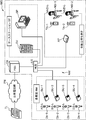
- FIG. 1 is an explanatory view for explaining the configuration of a monitored person monitoring system MS according to the embodiment.
- the monitored person monitoring system MS includes, for example, one or more of the sensor devices SU (SU-1 to SU-4), the management server device SV, the fixed terminal device SP, and one or more of them.
- a portable terminal device TA (TA-1, TA-2) and a private branch exchange (PBX, Private Branch eXchange) CX are provided, which are wired or wireless, and networks (networks, communications, etc. such as LAN (Local Area Network) Line) communicably connected via NW.
- the network NW may be equipped with relays such as repeaters, bridges and routers for relaying communication signals.
- relays such as repeaters, bridges and routers for relaying communication signals.
- the plurality of sensor devices SU-1 to SU-4, the management server SV, the fixed terminal SP, the plurality of portable terminals TA-1 and TA-2 and the private branch exchange CX are L2 switches.
- a wired / wireless mixed LAN for example, a LAN according to the IEEE 802.11 standard
- NW including the line concentrators (hub, HUB) LS and the access point AP.
- the plurality of sensor devices SU-1 to SU-4, the management server SV, the fixed terminal SP and the private branch exchange CX are connected to the line concentrator LS, and the plurality of mobile terminals TA-1 and TA-2 are connected.
- the network NW constructs a so-called intranet by using an internet protocol group such as TCP (Transmission Control Protocol) and IP (Internet Protocol).
- the private branch exchange CX is connected to the telephone TL by a public telephone network PN.
- the monitored person monitoring system MS is disposed at an appropriate place according to the monitored person Ob.
- the monitored person Ob is, for example, a person who needs nursing due to illness or injury, a person who needs care due to a decrease in physical ability or the like, or a single person living alone.
- the person to be monitored Ob is a person who needs the detection when a predetermined inconvenient event such as an abnormal condition occurs in the person. preferable.
- the to-be-monitored person monitoring system MS is suitably disposed in a building such as a hospital, a welfare institution for the elderly, and a dwelling unit according to the type of the person to be monitored Ob.
- the monitored person monitoring system MS is disposed in a building of a care facility provided with a plurality of living rooms RM in which a plurality of monitored persons Ob reside, and a plurality of rooms such as a nurse station.
- the sensor device SU has a communication function and the like for communicating with other devices SV, SP, and TA via the network NW, detects a predetermined event related to the monitored person Ob, and detects the detected event as the management server device SV. To the terminal apparatus SP and TA, and generates an image including a moving image and distributes the moving image to the terminal apparatus SP and TA.
- the predetermined event preferably includes an event that needs to be dealt with.
- first to fourth sensor devices SU-1 to SU-4 are shown in FIG. 1 as an example, and the first sensor device SU-1 is a person A who is one of the monitored persons Ob.
- the second sensor device SU-2 is disposed in a living room RM-1 (not shown) of Ob-1, and is disposed in a living room RM-2 (not shown) of Mr. B Ob-2 who is one of the monitored persons Ob.
- the third sensor unit SU-3 is installed in a room RM-3 (not shown) of Mr. C's Ob-3 who is one of the monitored persons Ob
- the fourth sensor unit SU-4 is It is disposed in a room RM-4 (not shown) of Mr. D's Ob-4 who is one of the monitored persons Ob.
- the management server SV has a communication function of communicating with other devices SU, SP, TA via the network NW, and receives a notification of a predetermined event related to the monitored person Ob from the sensor device SU. It is a device that manages information (monitoring information) related to monitoring of Ob.
- the management server device SV receives the first event notification communication signal as the notification of the event from the sensor device SU, the management server device SV relates to monitoring of the monitored person Ob based on the respective information contained in the first event notification communication signal. Monitoring information is stored (recorded), and a communication signal (second event notification communication signal) containing the monitoring information related to monitoring of the monitored person Ob is a predetermined terminal device associated in advance with the sensor device SU. Send to SP, TA.
- the management server device SV sends a sensor ID as a transmission source and a notification indicating the notification destination (renotification destination, re-notification destination, transmission destination) of the first event notification communication signal etc. transmitted from the sensor device SU.
- the correspondence (notification of correspondence) with the terminal ID that is the destination (renotification destination) and the communication address thereof are stored.
- the terminal ID (terminal device identifier) is an identifier for identifying and identifying the terminal device SP and TA.
- the management server device SV provides the client with data according to the request of the client (in the present embodiment, the fixed terminal device SP, the portable terminal device TA, etc.).
- Such a management server SV can be configured, for example, by a computer with a communication function.
- the fixed terminal device SP is a device that functions as a user interface (UI) of the monitored person monitoring system MS.
- the fixed terminal apparatus SP has a communication function of communicating with other apparatuses SU, SV, TA via the network NW, a display function of displaying predetermined information, and predetermined instructions and data. It has an input function and the like to be input, and it inputs predetermined instructions and data to be given to the management server device SV and the portable terminal device TA, and displays monitoring information obtained by the sensor device SU.
- Such fixed terminal apparatus SP can be configured, for example, by a computer with a communication function.
- the mobile terminal device TA is carried by the supervisor NS.
- the portable terminal device TA has a communication function of communicating with other devices SV, SP, SU via the network NW, a display function of displaying predetermined information, an input function of inputting predetermined instructions and data, and a voice call. It has a call function to be performed, etc., inputs predetermined instructions and data to be given to the management server device SV and the sensor device SU, or receives monitoring information (including a moving image) obtained by the sensor device SU by notification from the management server device SV. It is a device for displaying or answering a nurse call or making a voice by voice communication with the sensor unit SU.
- the sensor device SU is attached to the ceiling of the living room RM.
- the sensor device SU determines the degree of independence of the monitored person Ob in addition to the functions described above (for example, the function of capturing the moving image of the monitored person Ob and the function of making a voice call with the terminal devices SP and TA).
- Have a function to The sensor unit SU will be described in detail from the viewpoint of this function.
- FIG. 2 is a block diagram showing the configuration of the sensor unit SU.
- the sensor device SU includes a sensor control processing unit (SU control processing unit) 10, a sensor communication interface unit (SU communication IF unit) 11, an imaging unit 12, a storage unit 13, a detection unit 14, and an estimation unit. 15, a specifying unit 16, a first determination unit 17, and a second determination unit 18.
- the SU control processing unit 10 includes each unit (SU communication IF unit 11, imaging unit 12, storage unit 13, detection unit 14, estimation unit 15, identification unit 16, first determination unit 17, second determination unit 18 of the sensor device SU). ) Are detected according to the functions of the respective units, a predetermined event related to the monitored person Ob is detected, the detected event is notified to the management server apparatus SV, and voice is transmitted between the terminal apparatus SP and TA. It is a device for making a call and distributing an image including a moving image to the terminal devices SP and TA.
- the SU control processing unit 10 includes, for example, hardware such as a central processing unit (CPU), a random access memory (RAM), a read only memory (ROM), a hard disk drive (HDD), and the SU control processing unit 10.
- CPU central processing unit
- RAM random access memory
- ROM read only memory
- HDD hard disk drive
- DSP Digital Signal Processor
- the SU control processing unit 10 may be realized by processing by a dedicated hardware circuit instead of or in addition to processing by software.
- the detection unit 14 the estimation unit 15, the identification unit 16, the first determination unit 17, and the second determination unit 18.
- Programs are stored. These programs are expressed as an SU control processing program, a detection program, an estimation program, a specific program, a first determination program, and a second determination program.
- the detection unit and the detection program will be described as an example.
- the detection unit 14 detects the position of the monitored person Ob in the living room RM.
- the detection program is a program for detecting the position of the monitored person Ob in the living room RM.
- These programs are stored in advance in the HDD, but the present invention is not limited to this.
- a recording medium for example, an external recording medium such as a magnetic disk or an optical disk
- these programs may be stored in the management server SV connected to the sensor device SU via a network, and these programs may be sent to the HDD via the network and stored in the HDD.
- These programs may be stored in the ROM instead of the HDD.
- the sensor unit SU may include a flash memory instead of the HDD, and these programs may be stored in the flash memory.
- the SU communication IF unit 11 is a communication circuit which is connected to the SU control processing unit 10 and performs communication according to the control of the SU control processing unit 10.
- the SU communication IF unit 11 generates a communication signal containing the data to be transferred, which is input from the SU control processing unit 10, according to the communication protocol used in the network NW of the monitored person monitoring system MS, and the generated communication The signal is transmitted to the other devices SV, SP, TA via the network NW.
- the SU communication IF unit 11 receives communication signals from other devices SV, SP, and TA via the network NW, extracts data from the received communication signals, and the SU control processing unit 10 can process the extracted data.
- the data is converted into data of the following format and output to the SU control processing unit 10.
- the SU communication IF unit 11 includes, for example, a communication interface circuit conforming to the IEEE 802.11 standard or the like.
- the imaging unit 12 is an apparatus for imaging an imaging target and generating an image of the imaging target. Images include still images and moving images.
- the imaging unit 12 is arranged to be able to monitor the space where the monitored person Ob is planning to be located (location space; room RM in the arrangement location in the example shown in FIG. 1). An image is captured and an image in which the image capturing target is overlooked is generated.
- the imaging unit 12 is scheduled to locate the head of the subject Ob in the bedding (for example, a bed or the like) on which the subject Ob is lying, because the probability that the whole subject Ob can be imaged is high. It arrange
- the sensor unit SU uses the imaging unit 12 to obtain an image of the person to be monitored Ob, which is taken from above the person to be monitored Ob, preferably an image of the person to be monitored Ob, which is taken from directly above the planned head position.
- Such an imaging unit 12 may be a device (visible camera) that generates an image of visible light, but in the embodiment, an infrared image is generated so that the person to be monitored Ob can be monitored even with relatively darkness. It is an apparatus.
- Such an imaging unit 12 is disposed, for example, in the embodiment, an imaging optical system for forming an infrared optical image of an imaging target on a predetermined imaging surface, and a light receiving surface is made to coincide with the imaging surface
- An image sensor that converts an infrared optical image of the imaging target into an electrical signal; and image data processing of an output of the image sensor by image processing representing an infrared image of the imaging target It is a digital infrared camera including an image processing unit and the like to be generated.
- the imaging optical system of the imaging unit 12 is preferably a wide-angle optical system (a so-called wide-angle lens (including a fisheye lens)) having an angle of view capable of imaging the entire room RM provided.
- the storage unit 13 stores the moving image in the living room RM captured by the imaging unit 12. In addition, the storage unit 13 stores, in advance, position information PI of the area where the monitored person Ob acts in the living room RM. Furthermore, the storage unit 13 stores a table 70 shown in FIG. 8 described later and a template of the table 70.
- the storage unit 13 is realized by, for example, an HDD, a flash memory, or the like.
- the behavior of the monitored person Ob is the behavior of the monitored person Ob in the living room RM, for example, washing hands, eating, and brushing teeth. The behavior includes, for example, living behavior performed in the living room RM such as eating, changing clothes, moving, and excretion.
- the area (place) where the person to be monitored Ob acts is, for example, in the case of a private room in a nursing home, the area where the bed is located, the area where the desk or chair for eating is located, the washroom is located Area where the toilet is located.
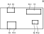
- FIG. 3 is a schematic view showing a state in which the region R where the monitored person Ob-1 acts is set as the still image 50 showing the room RM of the monitored person Ob-1.
- a bed area R-1 which is an area R in which the bed 51 is located
- a desk chair area R-2 which is an area R in which a desk and a chair 52 are located
- an area R in which a washroom 53 is located.
- a toilet area R-3 which is an area
- a toilet area R-4 which is an area R in which the toilet 54 is located, are respectively set.
- the position information PI includes coordinates indicating the position of the region R in the still image 50, and character data (for example, a bed) indicating what an object located in the region R is.
- the detection part 14 detects the position in the living room RM of the to-be-monitored person Ob.
- the detection unit 14 detects the position of the monitored person Ob in the living room RM using the moving image of the monitored person Ob captured in the living room RM.
- the storage unit 13 stores a 24-hour moving image in the living room RM, which is imaged by the imaging unit 12. Since this 24-hour moving image and the still image 50 shown in FIG. 6 were imaged by the same imaging unit 12, the position of the region R on each frame (image) constituting the 24-hour moving image and the region R on the still image 50 Position is the same. Therefore, the position information PI can be applied to each frame (image) constituting a 24-hour moving image.
- the SU control processing unit 10 stores in advance information of a time zone (for example, a lunch time zone) where it is desired to specify the behavior pattern of the monitored person Ob, and in the 24 hour moving image captured by the imaging unit 12 A moving image of a time zone in which it is desired to specify the action pattern of the person Ob is taken out from the storage unit 13 and sent to the detection unit 14.
- the detection unit 14 extracts a moving body region for each frame (image) constituting the moving image, using, for example, a background difference or an optical flow, and regards the extracted moving body region as a human region. Calculate the coordinates of This coordinate is taken as the position of the person to be monitored Ob in the living room RM.
- the estimation unit 15 estimates the action of the monitored person Ob based on the position of the monitored person Ob detected by the detecting unit 14 and the position information PI stored in advance in the storage unit 13. This will be specifically described.
- the monitored person Ob has lunch at a predetermined lunch time zone (for example, from 12:00 to 1:30).
- the lunch hours include the time to wash hands before lunch and the time to brush teeth after lunch.
- the estimation unit 15 estimates that the monitored person Ob has a meal when the position of the monitored person Ob is present in the desk chair area R-2 for a predetermined period T1 (for example, 10 minutes) or more in the lunch time zone. .
- the estimation unit 15 includes a period in which the position of the person to be monitored Ob is present in the desk and chair area R-2 (for example, a period from 12:05 to 12:25) including the predetermined period T1 as a meal time. presume.
- the estimating unit 15 presupposes that the monitored person Ob was hand-washed presume.
- the estimation unit 15 estimates that the monitored person Ob has brushed his / her teeth when the position of the monitored person Ob is present in the washroom area R-3 for a predetermined period T3 (for example, 3 minutes) or more after this meal time. Do.
- the estimation unit 15 estimates two behaviors (hand wash before and after meals, tooth brushing after meals) after meal estimation, but the monitored person Ob takes lunch time It is also possible to estimate all of the actions performed by the region R in the band in time series. That is, the estimation unit 15 estimates the first action performed by the monitored person Ob in the region R during the lunch time zone, estimates the second action, and estimates the second action,. Estimate the last action taken. Among these estimated behaviors, the estimation of a meal and the behaviors estimated before and after this are used to identify a behavior pattern.
- the estimating unit 15 determines that the monitored person Ob sleeps (sleeps in the bed 51) when the position of the monitored person Ob is present in the bed area R-1 for a predetermined period T4 or more (for example, 5 minutes) or more. presume. Further, the estimation unit 15 estimates that the monitored person Ob has excreted when the position of the monitored person Ob is present in the toilet area R-4 for a predetermined period T5 (for example, 2 minutes) or more.
- the identifying unit 16 identifies the behavior pattern of the monitored person Ob based on the behavior of the monitored person Ob estimated by the estimating unit 15.
- the behavior pattern is a pattern of behavior performed by the monitored person Ob in the living room RM, and is, for example, the following three.
- the estimating unit 15 estimates that the monitored person Ob has hand-washed before meals, and estimates that they have eaten and brushed their teeth after eating
- the identification unit 16 performs hand-washing, food and tooth-brushing in this order. Identify what you have acted as an action pattern.
- the estimation unit 15 estimates the meal time of the monitored person Ob.
- the identifying unit 16 identifies the estimated length of meal time (for example, 20 minutes) as a behavior pattern.
- the estimation unit 15 changes the first state to the second state.
- the time taken to change to the state is estimated to be the moving time for the monitored person Ob to move from the washroom 53 to the desk and chair 52 for eating.
- the identifying unit 16 identifies the estimated length of travel time as a behavior pattern.
- the estimation unit 15 estimates that the monitored person Ob is acting in the region R when the position of the monitored person Ob is present in the region R for a predetermined period or more.
- This predetermined period may be the same for all actions, or may be determined according to the type of action (meal, hand wash, tooth brushing, sleep, excretion) as described above.
- the first determination unit 17 determines whether the behavior pattern of the monitored person Ob identified by the identification unit 16 is different from a predetermined reference behavior pattern.
- the reference behavior pattern is a behavior pattern in which hand washing, eating, and tooth brushing are performed in this order.
- the first determination unit 17 determines that the behavior pattern of the monitored person Ob specified by the identification unit 16 is different from the reference behavior pattern when the behavior pattern is hand washing, eating, and sleeping in this order.
- the first determination unit 17 determines that the behavior pattern of the person to be monitored Ob identified by the identification unit 16 is the same as the reference behavior pattern when the behavior pattern includes hand washing, eating, and brushing teeth in this order. judge.
- the degree of independence of the person Ob to be monitored When the degree of independence of the person Ob to be monitored is low, the number of times that the behavior pattern of the person to be monitored Ob is determined to be different from the reference behavior pattern increases. On the other hand, when the degree of autonomy of the person to be monitored Ob is high, the number is zero or less. Therefore, the number of times can be used as an index for objectively determining the degree of independence of the person to be monitored Ob.
- the second determination unit 18 determines the number of times that the first determination unit 17 determines that the action pattern of the person to be monitored Ob differs from the reference action pattern (hereinafter may be referred to as “the number of different determinations”).
- the degree of independence of the monitored person Ob is determined as an indicator of the degree of independence of the monitored person Ob.
- the second determination unit 18 determines, for example, the degree of independence of the monitored person Ob by comparing a predetermined threshold value with the number of different determinations.
- the second determination unit 18 prepares in advance a first threshold and a second threshold as the threshold (first threshold ⁇ second threshold), and the number of different determinations is When it is smaller than 1 threshold, it is judged that the degree of independence of the person being monitored is high, and when the number of different determinations is at least the first threshold and smaller than the second threshold, the degree of independence of the person being monitored Ob Is determined to be low, and when the number of different determinations is equal to or greater than the second threshold value, it is determined that the degree of independence of the monitored person Ob is considerably low.
- the threshold may be one or plural.
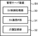
- FIG. 4 is a block diagram showing the configuration of the management server device SV.
- the management server device SV includes a management server side control processing unit (SV control processing unit) 30 and a management server side communication interface unit (SV communication IF unit) 31.
- SV control processing unit management server side control processing unit
- SV communication IF unit management server side communication interface unit
- the SV control processing unit 30 is a device for controlling each part of the management server device SV according to the function of each part.
- an SV communication IF unit 31 is shown as each unit of the management server device SV.
- the components other than the SV communication IF unit 31 are omitted in FIG. 4 because they are not used in the description of the embodiment.
- the SV communication IF unit 31 is a communication circuit which is connected to the SV control processing unit 30 and performs communication in accordance with the control of the SV control processing unit 30.
- the SV communication IF unit 31 generates a communication signal containing the data to be transferred, which is input from the SV control processing unit 30, according to the communication protocol used in the network NW of the monitored person monitoring system MS, and the generated communication The signal is transmitted to the other devices SU, SP, TA via the network NW.
- the SV communication IF unit 31 receives communication signals from other devices SU, SP, TA via the network NW, extracts data from the received communication signals, and the SV control processing unit 30 can process the extracted data.
- the data is converted into data of the following format and output to the SV control processing unit 30.
- the SV communication IF unit 31 includes, for example, a communication interface circuit conforming to the IEEE 802.11 standard or the like.
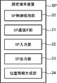
- FIG. 5 is a block diagram showing the configuration of the fixed terminal device SP.
- the fixed terminal device SP includes a fixed terminal side control processing unit (SP control processing unit) 20, a fixed terminal communication interface unit (SP communication IF unit) 21, and a fixed terminal input unit (SP input unit) 22.
- SP control processing unit fixed terminal side control processing unit
- SP communication IF unit fixed terminal communication interface unit
- SP input unit fixed terminal input unit
- SP output unit terminal side output unit
- a position information generation unit 24 are provided.
- the SP control processing unit 20 is a device for controlling each unit (SP communication IF unit 21, SP input unit 22, SP output unit 23, position information generation unit 24) of the fixed terminal apparatus SP according to the function of each unit. It is.
- the SP communication IF unit 21 is a communication circuit which is connected to the SP control processing unit 20 and performs communication according to the control of the SP control processing unit 20.
- the SP communication IF unit 21 generates a communication signal containing the data to be transferred, which is input from the SP control processing unit 20, according to the communication protocol used in the network NW of the monitored person monitoring system MS, and the generated communication The signal is transmitted to the other devices SU, SV, TA via the network NW.
- the SP communication IF unit 21 receives communication signals from other devices SU, SV, TA via the network NW, extracts data from the received communication signals, and the SP control processing unit 20 can process the extracted data.
- the data is converted into data of the following format and output to the SP control processing unit 20.
- the SP communication IF unit 21 includes, for example, a communication interface circuit conforming to the IEEE 802.11 standard or the like.
- the SP input unit 22 is a device that performs various inputs.
- the various inputs are to input commands (instructions), data, etc. from the outside of the fixed terminal apparatus SP.
- the SP input unit 22 is realized by a touch panel, a keyboard, a mouse or the like.
- the SP output unit 23 is a device that performs various outputs.
- the various outputs are, for example, an output of a command, data and the like input from the SP input unit 22, an output of an image (moving image, still image) obtained by imaging each living room RM, and an output of a care record.
- the SP output unit 23 is realized by a display device (liquid crystal display, organic EL display or the like) or a printing device (printer or the like).
- the position information generation unit 24 generates position information PI of the area R in which the monitored person Ob acts.
- the generation of the position information PI will be described by taking the room RM of the monitored person Ob-1 as an example.
- the user of the person-to-be-monitored monitoring system MS operates the SP input unit 22 to set the imaging unit 12 in the room RM of the person to be monitored Ob-1 to this room RM.
- Input an instruction to capture a still image of
- the SP control processing unit 20 transmits this command to the SP communication IF unit 21 with the first sensor device SU-1 as a destination.
- the SU control processing unit 10 causes the imaging unit 12 to capture a still image.
- FIG. 6 is a schematic view showing an example of the still image 50. As shown in FIG. In the still image 50, a bed 51, a desk and chair 52 for eating, a washroom 53, and a toilet 54 are shown. The washroom 53 and the toilet 54 are not private rooms, and the walls and doors that form these spaces do not exist.
- FIG. 3 is a diagram showing a state in which the region R is set.
- the user of the monitored person monitoring system MS operates the SP input unit 22, and the bed 51 captured in the still image 50, a desk and a chair for eating For each of 52, washroom 53, and toilet 54, input is made to specify the four corners.
- the position information generation unit 24 sets the bed area R-1, the desk chair area R-2, the washroom area R-3, and the toilet area R-4 as the still picture 50.
- the user of the person-to-be-monitored monitoring system MS operates the SP input unit 22 to select the bed area R-1, and inputs the word “bed”.
- the position information generation unit 24 associates position information PI in which the coordinates (the coordinates of each of the four corners of the bed 51) defining the bed area R-1 in the still image 50 and the character "bed” are linked. Generate This is position information PI of the bed area R-1.
- position information PI of the desk chair area R-2, position information PI of the washroom area R-3, and position information PI of the toilet area R-4 are generated.
- the user of the monitored person monitoring system MS operates the SP input unit 22 to input an instruction to register the position information PI in the first sensor unit SU-1.
- the SP control processing unit 20 causes the SP communication IF unit 21 to transmit this command and position information PI (here, four pieces of position information PI) to the first sensor device SU-1 as a destination.
- the SU communication IF unit 11 of the first sensor unit SU-1 receives this command and the position information PI, and the SU control processing unit 10 stores the position information PI received by the SU communication IF unit 11 in the storage unit 13.
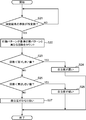
- FIG. 7 is a flow chart for explaining the operation of the sensor unit SU in this operation. Since the monitored person Ob-1 is taken as an example, the sensor device SU is the first sensor device SU-1.
- the person-to-be-monitored monitoring system MS monitors whether the behavior pattern of the person to be monitored Ob-1 is different from the reference behavior pattern, and determines the degree of independence of the person to be monitored Ob-1 based on this.
- the action pattern is the action pattern of (1) above.
- the standard behavior pattern is to do in this order for washing hands, meals, and brushing teeth.
- SU control processing unit 10 prestores information on a lunch time zone (for example, from 12:00 to 13:00) of monitored person Ob-1.
- the imaging unit 12 images a moving image in the room RM of the monitored person Ob-1 for 24 hours and stores the moving image in the storage unit 13 (step S1).
- the SU control processing unit 10 copies the moving image in the lunch time zone of the monitored person Ob in the 24-hour moving image stored in the storage unit 13 and sends it to the detecting unit 14.
- the detection unit 14 performs processing for detecting the position of the person to be monitored Ob-1 in the frame (image) for each frame (each image) constituting the moving image (step S2).
- the estimating unit 15 selects the monitored person Ob-1 based on the position of the monitored person Ob-1 in the lunch time zone detected in step S2 and the position information PI stored in advance in the storage unit 13. It is determined whether or not the desk position exists in the desk chair area R-2 (FIG. 3) continuously for a predetermined period T1 (for example, 10 minutes) or more (step S3).
- the first determination unit 17 monitors the It is determined that the observer Ob-1 is not eating in the lunch time zone, and it is determined that the behavior pattern of the person to be monitored Ob-1 is different from the reference behavior pattern (step S4). Then, the first determination unit 17 records, as a determination result, that the behavior pattern of this lunch period differs from the reference behavior pattern in a table 70 illustrated in FIG. 8 described later (step S11). Here, since the behavior pattern of the monitored person Ob-1 is not specified, the behavior pattern of the monitored person Ob-1 is not recorded in the table 70.
- the estimation unit 15 determines that the position of the monitored subject Ob-1 continuously exists in the desk chair area R-2 for a predetermined period T1 or more (Yes in step S3), the monitored subject Ob-1 eats (Step S5). Then, the estimation unit 15 estimates the meal time of the monitored person Ob-1 (step S6). A period (for example, a period from 12:05 to 12:25) in which the position of the person to be monitored Ob is present in the desk and chair area R-2 including the predetermined period T1 is estimated to be the meal time.
- the estimation unit 15 determines the meal estimated in step S6 based on the position of the monitored person Ob-1 in the lunch time zone detected in step S2 and the position information PI stored in advance in the storage unit 13. Before the time, the action taken by the monitored person Ob-1 is estimated (step S7). For example, before the meal time estimated in step S6, the estimation unit 15 continues the position of the monitored person Ob-1 in the washroom area R-3 (FIG. 3) for a predetermined period T2 (for example, one minute). ) If there is more than one, it is estimated that the monitored person Ob-1 has washed his hands.
- the estimation unit 15 determines the meal estimated in step S6 based on the position of the monitored person Ob-1 in the lunch time zone detected in step S2 and the position information PI stored in advance in the storage unit 13. After the time, the action taken by the monitored person Ob-1 is estimated (step S8). For example, after the meal time estimated in step S6, the estimation unit 15 determines that the position of the monitored person Ob is continuously present in the washroom area R-3 for a predetermined period T3 (for example, 3 minutes) or more. It is estimated that the observer Ob brushed his teeth.
- the identifying unit 16 is monitored using the meal estimated in step S5, the behavior estimated in step S7 (pre-meal behavior), and the behavior estimated in step S8 (post-meal behavior).
- the action pattern of person Ob-1 is specified (step S9).
- the action estimated in step S7 is hand washing
- the action estimated in step S8 is toothpaste.
- the identification unit 16 identifies hand washing, eating, and brushing teeth in this order as the behavior pattern of the monitored person Ob-1.
- the specifying unit 16 specifies that hand washing, eating and sleeping in this order is the behavior pattern of the monitored person Ob-1.
- the first determination unit 17 determines whether the behavior pattern identified in step S9 is different from the reference behavior pattern (step S10).
- the behavior pattern identified by the identification unit 16 here, for example, the hand wash, With regard to meals and sleep, behavior patterns in this order and that this behavior pattern differs from the reference behavior pattern are recorded as a determination result in a predetermined table 70 shown in FIG. 8 (step S12).
- the behavior pattern identified in step S9 is the same as the reference behavior pattern (No in step S10)
- the behavior pattern identified by the identification unit 16 here, The behavior patterns of handwashing, eating and brushing teeth in this order are recorded as a determination result in a predetermined table shown in FIG. 8 (step S13).
- the first sensor device SU-1 ends monitoring of whether the behavior pattern of the person to be monitored Ob-1 is different from the reference behavior pattern with respect to today.
- the first sensor unit SU-1 repeats the processing of the flowchart shown in FIG. 7 every day.
- FIG. 8 is an explanatory diagram for explaining an example of the table 70 in which the behavior pattern of the person to be monitored Ob identified by the identifying unit is recorded.
- the table 70 includes the reference behavior pattern, the contents of the behavior pattern identified daily by the identifying unit 16, and a symbol (check symbol) indicating that the activity pattern is different from the reference behavior pattern.
- the determination result of step S4 since the action pattern is not specified by the specifying unit 16, the contents of the action pattern are not recorded in the table 70.
- the table 70 shown in FIG. 8 is an example which does not include the determination result of step S4.
- the first sensor device SU-1 uses the table 70 to determine the degree of independence of the monitored person Ob-1.
- FIG. 9 is a flowchart illustrating this process.
- second determination unit 18 determines whether or not the number of days of the determination result recorded in table 70 has reached a predetermined number (step S21).
- the predetermined number is, for example, 10 days.
- the predetermined number is not limited to 10 days, and may be 7 days or 30 days.
- the predetermined number is a number necessary for objective determination of the degree of independence, and should not be too small (for example, 2 days).
- the action of the monitored person Ob-1 identified by the identification unit 16 The pattern counts the number of times different from the reference behavior pattern (number of different determinations) (step S22). Specifically, the second determination unit 18 counts the number of check symbols (that is, symbols indicating that the behavior pattern is different from the reference behavior pattern) recorded in the table 70 in 10 days. In the case of the table 70 shown in FIG.
- the second determination unit 18 determines the degree of independence of the monitored person Ob-1 using the number of different determinations (the number counted in step S22) and the threshold value.
- the first threshold and the second threshold are used as the threshold (first threshold ⁇ second threshold).
- the first threshold is 2 and the first threshold is two. 2 Assume that the threshold is 8.
- the second determination unit 18 determines whether the number of different determinations is smaller than the first threshold (step S23). When the second determination unit 18 determines that the number of different determinations is smaller than the first threshold (Yes in step S23), the monitored person Ob-1 determines that the degree of independence is high regarding the reference behavior pattern ( Step S24).
- the second determination unit 18 determines whether the number of different determinations is smaller than the second threshold (step S25). ).
- the monitored person Ob-1 determines that the degree of independence is low regarding the reference behavior pattern ( Step S26).
- the second monitoring unit 18 determines that the monitored person Ob-1 has a fairly low degree of independence regarding the reference behavior pattern (Ste S27).
- the SU control processing unit 10 transmits a notification signal including the determination result of the degree of independence (step S24, step S26, step S27) to the fixed terminal apparatus SP as a destination.
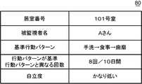
- FIG. 10 is an explanatory view for explaining an example of the notification image 80.
- the notification image 80 includes a room number, the name of the monitored person Ob, a reference behavior pattern in the lunch time zone, the number of different determinations, and the determination result of the degree of independence.
- the SP control processing unit 20 causes the display constituting the SP output unit 23 to display the notification image 80. Thereby, the user of the person-to-be-monitored monitoring system MS can know the objective independence degree of the person to be monitored Ob-1 with respect to the reference behavior pattern in the lunch time zone.
- the specification of the action pattern shown in the above (1) has been described.
- the specification of the action pattern shown in the above (2) will be briefly described using three specific examples. Referring to FIGS. 2 and 7, as a length of time for hand washing before meals, 1 minute to 2 minutes is taken as a reference behavior pattern.
- the estimation unit 15 determines the meal estimated in step S6 based on the position of the monitored person Ob-1 in the lunch time zone detected in step S2 and the position information PI stored in advance in the storage unit 13. Before time, the time when the position of the monitored person Ob-1 existed in the washroom area R-3 is measured.
- the identifying unit 16 identifies the length of the time measured by the estimating unit 15 as an action pattern relating to the length of time of hand washing of the monitored person Ob-1.
- the identifying unit 16 identifies the length of the meal time estimated in step S6 by the estimating unit 15 as a behavior pattern related to the length of the meal time of the monitored person Ob-1.
- the estimation unit 15 determines the meal estimated in step S6 based on the position of the monitored person Ob-1 in the lunch time zone detected in step S2 and the position information PI stored in advance in the storage unit 13. After the time, the time when the position of the monitored person Ob-1 existed in the washroom area R-3 is measured. The identifying unit 16 identifies the length of time measured by the estimating unit 15 as a behavior pattern regarding the length of time of brushing of the monitored person Ob-1.
- the specification of the action pattern shown in the above (3) will be briefly described using two specific examples.
- FIG. 2, FIG. 3 and FIG. 7, as a length of moving time to move from the washroom 53 to the desk / chair 52 to eat before eating (in other words, the time from the end of hand washing to the start of eating) Length) and within 1 minute are taken as reference behavior patterns.
- the estimation unit 15 exists in the desk and chair area R-2 after the period when the position of the monitored person Ob-1 exists in the washroom area R-3 before the meal time estimated in step S6. Measure the time until the period starts.
- the estimation unit 15 makes this measurement based on the position of the monitored person Ob-1 in the lunch time zone detected in step S2, and the position information PI stored in advance in the storage unit 13.
- the identifying unit 16 acts on the length of the moving time in which the monitored person Ob-1 moves from the washroom 53 to the desk / chair 52 where he / she eats before eating. Identify as a pattern.
- the estimation unit 15 determines that the position of the person to be monitored Ob-1 is present in the washroom area R-3 after the end of the period in which the position of the monitored person Ob-1 is present in the desk chair area R-2 after the meal time estimated in step S6. Measure the time it takes to start. The estimation unit 15 makes this measurement based on the position of the monitored person Ob-1 in the lunch time zone detected in step S2, and the position information PI stored in advance in the storage unit 13. The identifying unit 16 determines the length of the time measured by the estimating unit 15 according to the movement pattern of the moving time for the monitored person Ob-1 to move from the desk / chair 52 eating to the washroom 53 after eating. Identify as
- the reference behavior pattern may be the same for all the monitored persons Ob, or may be determined for each of the monitored persons Ob. The latter will be described by taking an action pattern in a lunch time zone as an example.
- the identification unit 16 executes identification of the behavior pattern in the lunch hour every day, and stores it in the storage unit 13. When the number of behavior patterns stored in the storage unit 13 exceeds a predetermined threshold (for example, the same behavior pattern is 20 days or more in 30 days), the SU control processing unit 10 references the behavior pattern. It is stored in the storage unit 13 as an action pattern. Three specific examples will be described.
- the behavior pattern of the monitored person Ob-1 in this order for lunch, tooth brushing, and leaving the living room RM in the lunch time zone is stored in the storage unit 13 provided in the first sensor device SU-1. Within 30 days, this behavior pattern has occurred for 26 days.
- the SU control processing unit 10 included in the first sensor unit SU-1 stores this behavior pattern in the storage unit 13 included in the first sensor unit SU-1 as a reference behavior pattern of the monitored person Ob-1. .
- the SU control processing unit 10 included in the first sensor unit SU-1 stores this behavior pattern in the storage unit 13 included in the first sensor unit SU-1 as a reference behavior pattern of the monitored person Ob-1. .
- the behavior pattern in which the monitored person Ob-2 puts in order the lunch, tooth brushing, and sleep in the lunch time zone is stored in the storage unit 13 provided in the second sensor device SU-2. Within 30 days, this behavior pattern has occurred for 24 days.
- the SU control processing unit 10 included in the second sensor unit SU-2 stores this behavior pattern in the storage unit 13 included in the second sensor unit SU-2 as the reference behavior pattern of the monitored person Ob-2. .
- FIG. 11 is a block diagram showing the configuration of the management server SV provided in the modification.
- the management server device SV in addition to the SV control processing unit 30 and the SV communication IF unit 31, the management server device SV according to the modification further includes a care recording unit 32.
- the care record unit 32 stores the care record of the monitored person Ob.
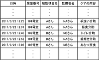
- FIG. 12 is an explanatory view for explaining a part of an example of a care record.
- the care record records the content of care in chronological order.
- the care record is composed of the date and time of care, the number of the room RM in which the care was taken, the name of the monitored person who received the care, the name of the monitored person who performed the care, and the content of the care.
- the observer NS takes care of the monitored person Ob, he creates a care record.
- the care record is created using the mobile terminal device TA.
- the supervisor NS creates a care record by inputting a care record on a care record input screen (not shown) displayed on the portable terminal device TA.
- the portable terminal device TA transmits the care record to the management server device SV, and the management server device SV causes the care record unit 32 to record the care record.
- the care record may be created using the fixed terminal device SP.
- the supervisor NS creates a care record by inputting a care record on a care record input screen (not shown) displayed on the fixed terminal device SP.
- the fixed terminal device SP transmits the care record to the management server device SV, and the management server device SV causes the care recording unit 32 to record the care record.
- the care record is not created using the monitored person monitoring support device configured by the sensor device SU and the management server device SV, but a device different from this device (mobile terminal device TA, fixed It is created using the terminal device SP).
- the care recording unit 32 stores in advance a table indicating the relationship between the content of care and the action of the person to be monitored Ob corresponding thereto. For example, when the content of care is "Lunch assistance”, the behavior of the monitored person Ob corresponding to this is “meal”, and when the content of care is “Hand wash assistance”, the corresponding monitored person Ob's The action is “hand-washing”, and when the content of care is “dentification aid", the corresponding action of the person to be monitored Ob is "dentification”.
- the care recording unit 32 When recording the content of the care, the care recording unit 32 links the behavior of the person to be monitored Ob corresponding to the content to the content of the care and records it. For example, when recording “Lunch Assistance”, the care recording unit 32 links “Meal” to “Lunch Assistance” and records. Therefore, the care record includes the first action information.
- the first action information is information indicating the action of the person to be monitored Ob and the time when the action is performed, which is created using an apparatus different from the to-be-monitored person monitoring support apparatus.
- the configuration of the sensor unit SU according to the modification is the same as the configuration of the sensor unit SU shown in FIG.
- an SU control processing unit 10 and an SU communication IF unit 11 constitute an acquisition unit.
- the acquisition unit acquires the first behavior information from the care recording unit 32.
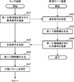
- FIG. 13 is a flowchart illustrating this operation. Since the monitored person Ob-1 is taken as an example, the sensor device SU is the first sensor device SU-1.
- the SU control processing unit 10 performs the lunch time on this day (for example, March 23, 2017)
- the SU communication IF unit 11 transmits a request signal for requesting the first action information of the monitored person Ob-1 (step S41).
- the destination of the request signal is the management server SV.
- the address of the sensor device SU that has sent the request signal here, the address of the first sensor device SU-1
- the room number where the sensor device SU is disposed here, 101
- the SV communication IF unit 31 receives the transmitted request signal (step S42), and the SV control processing unit 30 generates the first activity information corresponding to the room number included in the request signal in the care recording unit 32. (Step S43).
- it is the first action information of the monitored person Ob-1 in the lunch time zone of March 23, 2017.
- the content of the care of the monitored person Ob-1 (Mr. A) is "hand wash assistance", and on March 23, 2017, 12:31.
- the content of care of the monitored person Ob-1 (Mr. A) is "Lunch Assistance”.
- the care record unit 32 generates first behavior information including "March 23, 2017 12:25: Hand wash” and "March 23, 2017 12:31: Meal".
- the SV control processing unit 30 causes the SV communication IF unit 31 to transmit a response signal including the first action information generated in step S43, with the address included in the request signal received in step S42 as the destination (step S44). ).
- the SU communication IF unit 11 receives the transmitted response signal (step S45), and the SU control processing unit 10 sends the first action information included in the response signal to the specifying unit 16.
- the estimation unit 15 generates second action information related to the monitored person Ob-1 (step S46). For example, in the lunchtime zone on March 23, 2017 (from 12:00 to 1:30, 00) (for example, 12:50), the position of the monitored person Ob-1 is shown in FIG. It is assumed that the bed area R-1 shown in 3 exists for a predetermined period T4 (for example, 5 minutes) or more. In this case, the estimation unit 15 estimates that the monitored person Ob sleeps, and generates second action information ("March 23, 2017 12:50: sleep").
- the identifying unit 16 identifies the action pattern of the person to be monitored Ob-1 based on the first action information and the second action information (step S47).
- the specifying unit 16 specifies an action pattern in which the hand wash, the meal, and the sleep are performed in order.
- the first sensor device SU-1 performs the process of step S10 shown in FIG.
- the subsequent processing is the same as that of the monitored person monitoring support device MS according to the embodiment.
- the variation presupposes that the action pattern is the order of performing a plurality of actions.
- all of the plurality of actions are not the actions estimated by the estimation unit 15.
- Some of the plurality of actions are first action information created using a device different from the monitored person monitoring support device include.
- the first behavior information is, for example, a care record.
- the monitored person Ob may receive care from the observer NS with respect to some of various daily activities.
- the supervisor NS provides dietary assistance.
- the monitor NS records meal assistance and the time of the assistance as a care record. This record is used to identify behavior patterns.
- the number of times the behavior pattern of the monitored person Ob is determined to be different from the reference behavior pattern is used as an index of the degree of independence of the monitored person Ob.
- the invention is not limited to this, and a value obtained based on the number of times may be used as an indicator of the degree of independence of the person to be monitored Ob. As such a value, for example, there is a ratio and the number of continuous times.
- the ratio is the number of times the behavior pattern of the monitored person Ob is determined to be the same as the reference behavior pattern (the first number of times) and the number of times the behavior pattern of the monitored person Ob is determined different from the reference behavior pattern (the second number The value obtained by adding the number of times and) is a denominator, and the second number is a numerator.
- the number of consecutive times is the number of consecutive judgments in which the behavior pattern of the person to be monitored Ob differs from the reference behavior pattern. If this determination continues, it can be considered that the monitored person Ob can not suddenly stop the reference behavior pattern.
- the second determination unit 18 determines that the degree of independence is high when the number of consecutive times is equal to or less than a predetermined threshold (fourth threshold) in a predetermined period, and the number of consecutive times indicates the fourth threshold. When exceeding, it is determined that the degree of independence is low. For example, in the predetermined period, the number of consecutive times is 12, and the fourth threshold is 9. The second determination unit 18 determines that the degree of independence is low because the number of consecutive times (12) exceeds the fourth threshold (9).
- the number of times may be weighted.
- the number is not set to 1 each time, but the number is increased as the number increases.
- the number of consecutive determinations in which the behavior pattern of the person to be monitored Ob differs from the reference behavior pattern is three.
- the first number is 1, the second number is 3, and the third number is 6.
- the second determination unit 18 determines that the degree of independence is low because the number of consecutive times (10) exceeds the fourth threshold (9). .
- the sensor device SU includes the storage unit 13, the detection unit 14, the estimation unit 15, the identification unit 16, the first determination unit 17, and the second determination unit 18.
- the present invention is not limited to this, and the management server device SV may include these.
- the number of imaging units 12 included in the sensor device SU is one, but the present invention is not limited to this, and a plurality of imaging units 12 may be provided. That is, when only one imaging unit 12 can not cope with imaging of the person to be monitored Ob, the other imaging units 12 cover.
- a plurality of visible cameras are used. For example, if it is desired to cover both daytime and nighttime, a visible camera and an infrared camera are used.
- a visible camera and infrared thermography are used.
- the present invention is not limited to this, and can be applied to, for example, a standalone cloud system.
- an identifying unit that identifies an activity pattern of the monitored person, and the behavior pattern of the monitored person identified by the identifying unit are: The number of times the first determination unit determines whether or not the behavior pattern differs from the predetermined reference behavior pattern, and the number of times the determination of the behavior pattern of the person to be monitored is different from the reference behavior pattern or by the first determination unit And a second determination unit that determines the degree of independence of the person to be monitored as a measure of the degree of independence of the person to be monitored.
- the behavior pattern is a pattern of the behavior of the monitored person in the room, and is, for example, the following three.
- the number of times the behavior pattern of the person being monitored is determined to be different from the reference behavior pattern increases.
- this number is zero or less. Therefore, the number of times can be used as an index to objectively determine the degree of independence of the person to be monitored regarding the reference behavior pattern.
- the second determination unit determines, for example, the degree of independence of the monitored person by comparing a predetermined threshold value with the number of times. For example, the determination unit prepares in advance the first threshold and the second threshold as the threshold (first threshold ⁇ second threshold), and the number of times is greater than the first threshold. When it is smaller, it is determined that the degree of independence of the person being monitored is high, and when the number of times is greater than or equal to the first threshold and less than the second threshold, it is determined that the degree of independence of the person being monitored is low. When is greater than or equal to the second threshold, it is determined that the degree of independence of the monitored person is considerably low.
- the threshold may be one or plural. Instead of the above-mentioned number of times, a value (ratio or the like) obtained based on the above-mentioned number of times may be used.
- the objective determination of the independence degree of a to-be-monitored person can be assisted.
- the above configuration includes a storage unit that stores in advance the position information of the area where the person to be monitored acts in the room, a detection unit that detects the position of the person to be monitored in the room, the position information, and the position information
- the estimation unit further includes: an estimation unit configured to estimate an action of the monitored person using the position of the monitored person detected by the detection unit; and the identification unit is configured to estimate the monitored person estimated by the estimation unit.
- An action pattern of the person to be monitored is specified using an action.
- the area (place) where the person to be monitored acts is, for example, in the case of a single room of a nursing home, an area where a bed is located, an area where a desk or chair to eat, an area where a washroom is located, It is the area where the toilet is located.
- the behavior of the monitored person is the behavior of the monitored person indoors, for example, washing hands, eating, and brushing teeth.
- the behavior includes, for example, living behavior performed indoors such as eating, changing clothes, moving, and excretion.
- the estimation unit estimates the behavior of the person to be monitored based on the position information of the area and the position of the person to be monitored detected by the detection unit. For example, when the position of the person to be monitored exists in the area where the bed is located for a predetermined period or more, it is estimated that the person to be monitored is sleeping (sleeps in the bed). For example, when the estimation unit estimates that the monitored person has hand-washed, then estimates that he / she has eaten, and then brushed teeth, the identification unit is in the order of hand-washing, eating, and brushing teeth. , Identify that the person being monitored has acted as an action pattern.
- the detection unit detects the position of the monitored person in the room using the time-series image captured by the imaging unit for the monitored person in the room, and the position information is The position of the said area
- the imaging unit may be a visible camera, an infrared camera, or infrared thermography.
- each image constituting a time-series image is a visible image.
- each image constituting a time-series image is an infrared image.
- the time-series image has a configuration in which the images captured by the imaging unit are arranged in time series.
- time-series images there are moving images with arbitrary frame rates (for example, 24 fps, 15 fps, 10 fps, 1 fps).
- the frame is an image.
- the above configuration further includes an acquisition unit configured to acquire first behavior information indicating the behavior of the person to be monitored and the time when the behavior is created, using an apparatus different from the monitoring target apparatus for the person to be monitored.
- the identification unit is based on the second activity information indicating the behavior of the person to be monitored estimated by the estimation unit and the time when the activity is performed, and the first activity information acquired by the acquisition unit.
- the order in which a plurality of actions are performed is specified as the action pattern.
- the specifying unit includes second behavior information indicating the behavior of the person to be monitored estimated by the estimation unit and a time when the behavior is performed, and the first behavior information acquired by the acquiring unit. Based on the order, a plurality of actions are determined, and the plurality of actions arranged in the order are specified as the action pattern.
- the action pattern is the order of performing a plurality of actions.
- some of the plurality of actions are not the actions estimated by the estimation unit, but some of the actions are the first action information created using a device different from the monitored person monitoring support device included.
- the first behavior information is, for example, a care record.
- a cared person (an example of a person to be monitored) may receive care from a carer (an example of a surveillance person) with regard to a part of various daily activities. For example, a carer gives a meal assistance to a care recipient who needs a meal assistance. At this time, the care giver records meal assistance and the time of the assistance as a care record. This record is used to identify behavior patterns.
- the first action information may be stored in advance in a storage device provided in the monitored person monitoring support device, or may be stored in advance in a device (for example, a server) outside the monitored person monitoring support device.
- a device for example, a server
- the SU control processing unit and the SU communication IF unit constitute an acquisition unit.
- a specifying step of specifying a monitored person's behavior pattern, and the behavior pattern of the monitored person specified in the identifying step is The number of times or the number of times in which the behavior pattern of the person to be monitored is determined to be different from the reference behavior pattern in the first determination step of determining whether it is different from a predetermined reference behavior pattern or the first determination step
- the monitored person monitoring support method defines the monitored person monitoring support device according to the first aspect of the embodiment from the viewpoint of the method, and in the first aspect of the embodiment It has the same effect as the person-to-be-monitored support device concerned.
- a specifying step of specifying an activity pattern of the monitored person, and the behavior pattern of the monitored person specified in the identifying step is The number of times or the number of times in which the behavior pattern of the person to be monitored is determined to be different from the reference behavior pattern in the first determination step of determining whether it is different from a predetermined reference behavior pattern or the first determination step
- a program for monitoring and managing a person to be monitored from the viewpoint of the program. It has the same effect as the person-to-be-monitored support device concerned.
- the present invention it is possible to provide a to-be-monitored person monitoring support device, a to-be-monitored person monitoring support method, and a to-be-monitored person monitoring support program.
Landscapes
- Business, Economics & Management (AREA)
- Emergency Management (AREA)
- Physics & Mathematics (AREA)
- General Physics & Mathematics (AREA)
- Health & Medical Sciences (AREA)
- Nursing (AREA)
- Life Sciences & Earth Sciences (AREA)
- Animal Behavior & Ethology (AREA)
- General Health & Medical Sciences (AREA)
- Public Health (AREA)
- Veterinary Medicine (AREA)
- Engineering & Computer Science (AREA)
- Multimedia (AREA)
- Signal Processing (AREA)
- Alarm Systems (AREA)
- Invalid Beds And Related Equipment (AREA)
- Closed-Circuit Television Systems (AREA)
Abstract
被監視者監視支援装置は、室内において、被監視者の行動パターンを特定する特定部と、特定部によって特定された被監視者の行動パターンが、予め定められた基準行動パターンと異なるか否かを判定する第1判定部と、第1判定部によって、被監視者の行動パターンが基準行動パターンと異なる判定がされた回数または回数を基にして求められた値を、被監視者の自立度の指標として、被監視者の自立度を判定する第2判定部と、を備える。
Description
本発明は、被監視者の監視を支援する技術に関する。
近年、超高齢社会の突入に伴って、看護業界、介護業界等の業務を補完する技術の研究、開発が進められている。このような技術として、例えば、特許文献1および特許文献2がある。特許文献1は、見守り対象者の所持する通信装置から位置情報を取得する位置情報取得部と、位置情報に基づいて見守り対象者の自宅からの移動距離を算出する移動距離算出部と、見守り対象者の外出能力に関する属性として予め選択された外出タイプに応じて設定された外出危険度、および、算出された移動距離に応じて、見守り対象者の状態の異常度合いを示す異常状態推定値を算定する異常状態推定部と、算定された異常状態推定値が所定値を超えているか否かを判定し、算定された異常状態推定値が所定値を超えていると判定した場合に、見守り対象者の異常状態を検知したことを知らせるための異常検知通知を所定の通知先に行う異常検知通知部と、を備える見守りシステムを開示している。
特許文献2に開示された見守りシステムは、住居に設置された複数の子機と親機とを備える。各子機は、対象者を感知すると通知信号を親機に送信する。親機は、子機からの通知信号の時刻データと子機からの通知信号の時刻データとに基づいて、見守り対象者の寝室からトイレまでの移動時間を算出し、当該移動時間に基づき見守り対象者の歩速を算出する。
監視者および被監視者として、介護施設に入居している被介護者、および、そこで働く介護者を考える。介護者は、被介護者に対して、必要に応じてケアをする。例えば、自分でトイレに行けない被介護者に対して、介護者は、その被介護者をトイレに連れて行く。
被介護者のケアプランは、その被介護者の自立度によって変わる。ここでの自立度は、ケアプランを決める指標である。介護者は、被介護者の自立度を基にして、被介護者のケアプランを見直すことができる。
被介護者の自立度が徐々に低くなることがある。例えば、被介護者が、徐々に自分でトイレに行けなくなったり、被介護者が、自分で着替えをするのに要する時間が徐々に長くなったりすることがある。
被介護者の自立度が徐々に低くなっていることが分かれば、自立度がかなり低くなった段階よりも前の段階で、介護者は、ケアプランを見直すことができる。例えば、介護者が被介護者の介助をすることにより、被介護者の怪我を防止したり、介護者が被介護者の自立支援をすることにより、被介護者の自立度が低くなる速度を遅くすることができる。
一方、過剰なケアは、被介護者の自立度を低くする原因となる。例えば、トイレに自分で行ける被介護者に対して、危険を理由に、常に介護者がトイレに連れて行った場合、被介護者の身体が衰え、トイレに自分で行けなくなることが起こる可能性がある。
介護者が被介護者の自立度を客観的に判定することは難しい。また、センサを用いて、被介護者の位置、移動量、移動速度等を測定できるが、このような指標だけでは、被介護者の自立度を客観的に判定することは難しい。
本発明の目的は、被監視者の自立度の客観的な判定を支援できる被監視者監視支援装置、被監視者監視支援方法、および、被監視者監視支援プログラムを提供することである。
上述した目的を実現するために、本発明の一側面を反映した被監視者監視支援装置は、特定部と、第1判定部と、第2判定部と、を備える。前記特定部は、室内において、被監視者の行動パターンを特定する。前記第1判定部は、前記特定部によって特定された前記被監視者の前記行動パターンが、予め定められた基準行動パターンと異なるか否かを判定する。前記第2判定部は、前記第1判定部によって、前記被監視者の前記行動パターンが前記基準行動パターンと異なる判定がされた回数または前記回数を基にして求められた値を、前記被監視者の自立度の指標として、前記被監視者の自立度を判定する。
発明の1又は複数の実施形態により与えられる利点及び特徴は以下に与えられる詳細な説明及び添付図面から十分に理解される。これら詳細な説明及び添付図面は、例としてのみ与えられるものであり本発明の限定の定義として意図されるものではない。
以下、図面を参照して、本発明の1又は複数の実施形態が説明される。しかし、発明の範囲は、開示された実施形態に限定されない。
各図において、同一符号を付した構成は、同一の構成であることを示し、その構成について、既に説明している内容については、その説明を省略する。本明細書において、総称する場合には添え字を省略した参照符号で示し、個別の構成を指す場合には添え字を付した参照符号で示す。
実施形態に係る被監視者監視システムは、監視すべき監視対象である被監視者(言い換えれば、見守るべき見守り対象である見守り対象者)を複数の装置を用いて監視するシステムであり、端末装置と、前記端末装置と通信可能に接続され、被監視者に関わる所定のイベント(事象)を検知して前記イベントを前記端末装置へ通知する被監視者監視支援装置と、を備える。前記被監視者監視支援装置は、1個の装置で一体に構成されて良いが、本明細書では、被監視者監視支援装置は、センサ装置と、前記センサ装置及び前記端末装置それぞれと通信可能に接続される管理サーバ装置とを備えることで、2種類の各装置で別体に構成される。前記センサ装置は、被監視者に関わる前記所定のイベントを検知して前記管理サーバ装置へ通知(報知、送信)する。前記管理サーバ装置は、前記センサ装置から前記通知を受けると、前記通知を受けた前記イベントを管理するとともに前記イベントを前記センサ装置に対応付けられた所定の端末装置へ再通知(再報知、再送信)する。前記端末装置は、1種類の装置であって良いが、本明細書では、前記端末装置は、固定端末装置と携帯端末装置との2種類の装置である。これら固定端末装置と携帯端末装置との主な相違は、固定端末装置が固定的に運用され、携帯端末装置が例えば看護師や介護士等の監視者(ユーザ)に携行されて運用される点である。これら固定端末装置と携帯端末装置とは、略同様であるので、以下では、固定端末装置を主に説明する。
図1は、実施形態に係る被監視者監視システムMSの構成を説明する説明図である。被監視者監視システムMSは、より具体的には、例えば、1または複数のセンサ装置SU(SU-1~SU-4)と、管理サーバ装置SVと、固定端末装置SPと、1または複数の携帯端末装置TA(TA-1、TA-2)と、構内交換機(PBX、Private Branch eXchange)CXとを備え、これらは、有線や無線で、LAN(Local Area Network)等の網(ネットワーク、通信回線)NWを介して通信可能に接続される。ネットワークNWには、通信信号を中継する例えばリピーター、ブリッジ及びルーター等の中継機が備えられても良い。図1に示す例では、これら複数のセンサ装置SU-1~SU-4、管理サーバ装置SV、固定端末装置SP、複数の携帯端末装置TA-1、TA-2及び構内交換機CXは、L2スイッチの集線装置(ハブ、HUB)LS及びアクセスポイントAPを含む有線及び無線の混在したLAN(例えばIEEE802.11規格に従ったLAN等)NWによって互いに通信可能に接続されている。より詳しくは、複数のセンサ装置SU-1~SU-4、管理サーバ装置SV、固定端末装置SP及び構内交換機CXは、集線装置LSに接続され、複数の携帯端末装置TA-1、TA-2は、アクセスポイントAPを介して集線装置LSに接続されている。そして、ネットワークNWは、TCP(Transimission Control Protocol)及びIP(Internet Protocol)等のインターネットプロトコル群が用いられることによっていわゆるイントラネットを構成する。構内交換機CXは、公衆電話網PNによって電話TLと接続されている。
被監視者監視システムMSは、被監視者Obに応じて適宜な場所に配設される。被監視者Obは、例えば、病気や怪我等によって看護を必要とする者や、身体能力の低下等によって介護を必要とする者や、一人暮らしの独居者等である。特に、早期発見と早期対処とを可能にする観点から、被監視者Obは、例えば異常状態等の所定の不都合なイベントがその者に生じた場合にその発見を必要としている者であることが好ましい。このため、被監視者監視システムMSは、被監視者Obの種類に応じて、病院、老人福祉施設及び住戸等の建物に好適に配設される。図1に示す例では、被監視者監視システムMSは、複数の被監視者Obが入居する複数の居室RMや、ナースステーション等の複数の部屋を備える介護施設の建物に配設されている。
センサ装置SUは、ネットワークNWを介して他の装置SV、SP、TAと通信する通信機能等を備え、被監視者Obに関わる所定のイベントを検知してこの検知した前記イベントを管理サーバ装置SVへ通知し、端末装置SP、TAとの間で音声通話を行い、そして、動画を含む画像を生成して端末装置SP、TAへ動画を配信する装置である。前記所定のイベントは、好ましくは、対処が必要なイベントを含む。
図1には、一例として、4個の第1ないし第4センサ装置SU-1~SU-4が示されており、第1センサ装置SU-1は、被監視者Obの一人であるAさんOb-1の居室RM-1(不図示)に配設され、第2センサ装置SU-2は、被監視者Obの一人であるBさんOb-2の居室RM-2(不図示)に配設され、第3センサ装置SU-3は、被監視者Obの一人であるCさんOb-3の居室RM-3(不図示)に配設され、そして、第4センサ装置SU-4は、被監視者Obの一人であるDさんOb-4の居室RM-4(不図示)に配設されている。
管理サーバ装置SVは、ネットワークNWを介して他の装置SU、SP、TAと通信する通信機能等を備え、センサ装置SUから、被監視者Obに関わる所定のイベントの通知を受信すると被監視者Obに対する監視に関する情報(監視情報)を管理する装置である。管理サーバ装置SVは、センサ装置SUから前記イベントの通知として第1イベント通知通信信号を受信すると、前記第1イベント通知通信信号に収容された各情報に基づいて、被監視者Obに対する監視に関する前記監視情報を記憶(記録)し、そして、被監視者Obに対する監視に関する前記監視情報を収容した通信信号(第2イベント通知通信信号)を、前記センサ装置SUに予め対応付けられた所定の端末装置SP、TAに送信する。このために、管理サーバ装置SVは、センサ装置SUから送信された第1イベント通知通信信号等の通知先(再通知先、再報知先、送信先)を示す、送信元であるセンサIDと通知先(再通知先)である端末IDとの対応関係(通知先対応関係)、及び、その通信アドレスを記憶する。端末ID(端末装置識別子)は、端末装置SP、TAを特定し識別するための識別子である。そして、管理サーバ装置SVは、クライアント(本実施形態では固定端末装置SP及び携帯端末装置TA等)の要求に応じたデータを前記クライアントに提供する。このような管理サーバ装置SVは、例えば、通信機能付きのコンピュータによって構成可能である。
固定端末装置SPは、被監視者監視システムMSのユーザインターフェース(UI)として機能する装置である。この機能を達成するために、固定端末装置SPは、ネットワークNWを介して他の装置SU、SV、TAと通信する通信機能、所定の情報を表示する表示機能、及び、所定の指示及びデータを入力する入力機能等を備え、管理サーバ装置SV及び携帯端末装置TAに与える所定の指示及びデータが入力されたり、センサ装置SUで得られた監視情報を表示したりする。このような固定端末装置SPは、例えば、通信機能付きのコンピュータによって構成可能である。
携帯端末装置TAは、監視者NSが携帯している。携帯端末装置TAは、ネットワークNWを介して他の装置SV、SP、SUと通信する通信機能、所定の情報を表示する表示機能、所定の指示やデータを入力する入力機能、及び、音声通話を行う通話機能等を備え、管理サーバ装置SV及びセンサ装置SUに与える所定の指示及びデータを入力したり、管理サーバ装置SVからの通知によってセンサ装置SUで得られた監視情報(動画を含む)を表示したり、センサ装置SUとの間で音声通話によってナースコールの応答や声かけしたり等をするための機器である。
センサ装置SUは、居室RMの天井に取り付けられている。センサ装置SUは、上述した機能(例えば、被監視者Obの動画を撮像する機能、端末装置SP、TAとの間で音声通話をする機能)に加えて、被監視者Obの自立度を判定する機能を有する。この機能の観点からセンサ装置SUについて詳しく説明する。
図2は、センサ装置SUの構成を示すブロック図である。センサ装置SUは、センサ側制御処理部(SU制御処理部)10と、センサ側通信インターフェース部(SU通信IF部)11と、撮像部12と、記憶部13と、検知部14と、推定部15と、特定部16と、第1判定部17と、第2判定部18と、を備える。
SU制御処理部10は、センサ装置SUの各部(SU通信IF部11、撮像部12、記憶部13、検知部14、推定部15、特定部16、第1判定部17、第2判定部18)を当該各部の機能に応じてそれぞれ制御し、被監視者Obに関わる所定のイベントを検知してこの検知した前記イベントを管理サーバ装置SVへ通知し、端末装置SP、TAとの間で音声通話を行い、そして、動画を含む画像を端末装置SP、TAへ動画を配信するための装置である。
SU制御処理部10は、例えば、CPU(Central Processing Unit)、RAM(Random Access Memory)、ROM(Read Only Memory)、及び、HDD(Hard Disk Drive)等のハードウェア、並びに、SU制御処理部10の機能を実行するためのプログラムおよびデータ等によって実現される。SU制御処理部10の機能の一部又は全部は、CPUによる処理に替えて、又は、これと共に、DSP(Digital Signal Processor)による処理によって実現されてもよい。又、SU制御処理部10の機能の一部又は全部は、ソフトウェアによる処理に替えて、又は、これと共に、専用のハードウェア回路による処理によって実現されてもよい。以上説明したことは、検知部14、推定部15、特定部16、第1判定部17、第2判定部18、図4を用いて後で説明するSV制御処理部30、図5を用いて後で説明するSP制御処理部20、位置情報生成部24、図10を用いて後で説明するSV制御処理部30、介護記録部32についても同様のことが言える。これらの機能ブロック(SU制御処理部10等)は、ハードウェアプロセッサにより実現できると言うこともできる。
上記HDDには、センサ装置SUを構成する要素のうち、SU制御処理部10、検知部14、推定部15、特定部16、第1判定部17、および、第2判定部18を実現するためのプログラムが格納されている。これらのプログラムは、SU制御処理プログラム、検知プログラム、推定プログラム、特定プログラム、第1判定プログラム、第2判定プログラムと表現される。
これらのプログラムは、要素の定義を用いて表現される。検知部と検知プログラムを例にして説明する。検知部14は、居室RM内での被監視者Obの位置を検知する。検知プログラムは、居室RM内での被監視者Obの位置を検知するプログラムである。
上記CPUによって実行されるこれらのプログラム(SU制御処理プログラム、検知プログラム、推定プログラム、特定プログラム、第1判定プログラム、第2判定プログラム)のフローチャートが、後で説明する図7および図9である。
なお、これらのプログラムは、上記HDDに予め記憶されているが、これに限定されない。例えば、これらのプログラムを記録している記録媒体(例えば、磁気ディスク、光学ディスクのような外部記録媒体)が用意されており、この記録媒体に記憶されているプログラムが上記HDDに記憶されてもよい。また、これらのプログラムは、センサ装置SUとネットワーク接続された管理サーバ装置SVに格納されており、ネットワークを介して、これらのプログラムが上記HDDに送られ、上記HDDに記憶されてもよい。これらのプログラムは、上記HDDの替わりにROMに記憶してもよい。センサ装置SUは、上記HDDの替わりに、フラッシュメモリを備え、これらのプログラムはフラッシュメモリに記憶してもよい。
以上説明したプログラム、および、これを格納する記憶部(HDD等)について、図4を用いて後で説明するSV制御処理部30、図5を用いて後で説明するSP制御処理部20、位置情報生成部24、図10を用いて後で説明するSV制御処理部30、介護記録部32についても同様のことが言える。
SU通信IF部11は、SU制御処理部10に接続され、SU制御処理部10の制御に従って通信を行うための通信回路である。SU通信IF部11は、SU制御処理部10から入力された転送すべきデータを収容した通信信号を、この被監視者監視システムMSのネットワークNWで用いられる通信プロトコルに従って生成し、この生成した通信信号を、ネットワークNWを介して他の装置SV、SP、TAへ送信する。SU通信IF部11は、ネットワークNWを介して他の装置SV、SP、TAから通信信号を受信し、この受信した通信信号からデータを取り出し、この取り出したデータをSU制御処理部10が処理可能な形式のデータに変換してSU制御処理部10へ出力する。SU通信IF部11は、例えば、IEEE802.11規格等に従った通信インターフェース回路を備えて構成される。
撮像部12は、撮像対象を撮像し、撮像対象の画像を生成する装置である。画像には、静止画及び動画が含まれる。撮像部12は、被監視者Obが所在を予定している空間(所在空間、図1に示す例では配設場所の居室RM)を監視可能に配置され、所在空間を撮像対象としてその上方から撮像し、撮像対象を俯瞰した画像を生成する。好ましくは、被監視者Ob全体を撮像できる蓋然性が高いことから、撮像部12は、被監視者Obが横臥する寝具(例えばベッド等)における、被監視者Obの頭部が位置すると予定されている予め設定された頭部予定位置(通常、枕の配設位置)の直上から撮像対象を撮像できるように配設される。センサ装置SUは、この撮像部12によって、被監視者Obを、被監視者Obの上方から撮像した画像、好ましくは前記頭部予定位置の直上から撮像した画像を取得する。
このような撮像部12は、可視光の画像を生成する装置(可視カメラ)であって良いが、比較的暗がりでも被監視者Obを監視できるように、実施形態では、赤外線の画像を生成する装置である。このような撮像部12は、例えば、実施形態では、撮像対象における赤外の光学像を所定の結像面上に結像する結像光学系、前記結像面に受光面を一致させて配置され、前記撮像対象における赤外の光学像を電気的な信号に変換するイメージセンサ、及び、イメージセンサの出力を画像処理することで前記撮像対象における赤外の画像を表すデータである画像データを生成する画像処理部等を備えるデジタル赤外線カメラである。撮像部12の前記結像光学系は、実施形態では、その配設された居室RM全体を撮像できる画角を持つ広角な光学系(いわゆる広角レンズ(魚眼レンズを含む))であることが好ましい。
記憶部13は、撮像部12が撮像した居室RM内の動画を記憶する。また、記憶部13は、居室RM内において、被監視者Obが行動をする領域の位置情報PIを予め記憶する。さらに、記憶部13は、後で説明する図8に示すテーブル70、および、このテーブル70の雛形を記憶する。記憶部13は、例えば、HDD、フラッシュメモリ等によって実現される。被監視者Obの行動とは、被監視者Obが居室RM内でする行動であり、例えば、手を洗うこと、食事をすること、歯磨きをすることである。行動は、例えば、食事、更衣、移動、排泄等の居室RM内でされる生活行動を含む。
居室RM内において、被監視者Obが行動をする領域(場所)とは、例えば、介護施設の個室の場合、ベッドが位置する領域、食事をする机・椅子が位置する領域、洗面所が位置する領域、トイレが位置する領域等である。
位置情報PIは、各居室RMに応じて予め生成される。被監視者Ob-1の居室RMを例にして、位置情報PIについて説明する。図3は、被監視者Ob-1が行動をする領域Rが、被監視者Ob-1の居室RMを示す静止画50に設定された状態を示す模式図である。静止画50には、ベッド51が位置する領域Rであるベッド領域R-1、食事をする机・椅子52が位置する領域Rである机椅子領域R-2、洗面所53が位置する領域Rである洗面所領域R-3、トイレ54が位置する領域Rであるトイレ領域R-4がそれぞれ設定されている。位置情報PIは、静止画50での領域Rの位置を示す座標と、この領域Rに位置する物が何であるかを示す文字データ(例えば、ベッド)と、を含む。
図1および図2を参照して、検知部14は、被監視者Obの居室RM内での位置を検知する。例えば、検知部14は、居室RM内で撮像された被監視者Obの動画を用いて、被監視者Obの居室RM内での位置を検知する。詳しく説明すると、記憶部13は、撮像部12が撮像した、居室RM内の24時間の動画を記憶している。この24時間動画と図6に示す静止画50とは、同じ撮像部12で撮像されたので、24時間動画を構成する各フレーム(画像)上の領域Rの位置と静止画50上の領域Rの位置とは同じである。よって、位置情報PIは、24時間動画を構成する各フレーム(画像)にも適用できる。
SU制御処理部10は、被監視者Obの行動パターンを特定したい時間帯(例えば、昼食時間帯)の情報を予め記憶しており、撮像部12が撮像した24時間動画の中で、被監視者Obの行動パターンを特定したい時間帯の動画を、記憶部13から取り出し、検知部14へ送る。検知部14は、この動画を構成する各フレーム(画像)に対して、例えば、背景差分またはオプティカルフローを用いて、動体領域を抽出し、抽出した動体領域を人領域と見なし、人領域の重心の座標を算出する。この座標が、居室RM内での被監視者Obの位置とされる。
推定部15は、検知部14が検知した被監視者Obの位置と記憶部13に予め記憶されている位置情報PIとを基にして、被監視者Obの行動を推定する。これについて具体的に説明する。図2および図3を参照して、被監視者Obは、予め定められた昼食時間帯で(例えば、12時0分から13時0分)、昼食をとる。昼食時間帯は、昼食前に手洗いをする時間、および、昼食後に歯磨きをする時間を含む。推定部15は、昼食時間帯において、被監視者Obの位置が、机椅子領域R-2に所定期間T1(例えば、10分間)以上存在するとき、被監視者Obが食事をしたと推定する。推定部15は、所定期間T1を含む、被監視者Obの位置が机椅子領域R-2に存在している期間(例えば、12時5分から12時25分までの期間)を、食事時間と推定する。推定部15は、この食事時間より前に、被監視者Obの位置が、洗面所領域R-3に所定期間T2(例えば、1分間)以上存在したとき、被監視者Obが手洗いをしたと推定する。推定部15は、この食事時間より後に、被監視者Obの位置が、洗面所領域R-3に所定期間T3(例えば、3分間)以上存在したとき、被監視者Obが歯磨きをしたと推定する。
以上説明したように、推定部15は、食事の推定をした後、食事の前後の2つの行動(食事前の手洗い、食事後の歯磨き)を推定しているが、被監視者Obが昼食時間帯に領域Rでした行動の全てを時系列に推定してもよい。すなわち、推定部15は、被監視者Obが、昼食時間帯に領域Rで、最初にした行動を推定し、次にした行動を推定し、その次にした行動を推定し、・・・、最後にした行動を推定する。これら推定した行動の中から、食事の推定と、この前後に推定された行動とが、行動パターンの特定に用いられる。
推定部15は、被監視者Obの位置が、ベッド領域R-1に所定期間T4(例えば、5分間)以上存在するとき、被監視者Obが睡眠(ベッド51で寝ている)をしたと推定する。また、推定部15は、被監視者Obの位置が、トイレ領域R-4に所定期間T5(例えば、2分間)以上存在するとき、被監視者Obが排泄をしたと推定する。
特定部16は、推定部15によって推定された被監視者Obの行動を基にして、被監視者Obの行動パターンを特定する。行動パターンとは、被監視者Obが居室RM内でする行動のパターンであり、例示すると、以下の3つである。
(1)複数の行動をする順番
(2)ある行動をしている時間の長さ
(3)ある行動をする領域から次の行動をする領域へ移動する時間の長さ
(2)ある行動をしている時間の長さ
(3)ある行動をする領域から次の行動をする領域へ移動する時間の長さ
(1)について、具体的に説明する。推定部15が、被監視者Obが食事前に手洗いをしたと推定し、食事をしたと推定し、食事後に歯磨きをしたと推定したとき、特定部16は、手洗い、食事、歯磨きの順で行動したことを、行動パターンとして特定する。
(2)について、具体的に説明する。上述したように、推定部15は、被監視者Obの食事時間を推定する。特定部16は、この推定された食事時間の長さ(例えば、20分間)を、行動パターンとして特定する。
(3)について、具体的に説明する。推定部15は、被監視者Obの位置が、洗面所領域R-3に存在する第1状態から、机椅子領域R-2に存在する第2状態に変化したとき、第1状態から第2状態に変化するのに要した時間を、被監視者Obが洗面所53から、食事をする机・椅子52に移動する移動時間と推定する。特定部16は、この推定された移動時間の長さを、行動パターンとして特定する。
推定部15は、被監視者Obの位置が領域Rに所定期間以上存在したとき、被監視者Obがその領域Rで行動をしていると推定する。この所定期間は、全ての行動で同じにしてもよいし、上述したように、行動の種類(食事、手洗い、歯磨き、睡眠、排泄)に応じて定めてもよい。
第1判定部17は、特定部16によって特定された被監視者Obの行動パターンが、予め定められた基準行動パターンと異なるか否かを判定する。例えば、基準行動パターンが、手洗い、食事、歯磨を、この順番でする行動パターンとする。第1判定部17は、特定部16によって特定された被監視者Obの行動パターンが、手洗い、食事、睡眠を、この順番でする行動パターンのとき、基準行動パターンと異なると判定する。これに対して、第1判定部17は、特定部16によって特定された被監視者Obの行動パターンが、手洗い、食事、歯磨きを、この順番でする行動パターンのとき、基準行動パターンと同じと判定する。
被監視者Obの自立度が低いとき、被監視者Obの行動パターンが基準行動パターンと異なる判定がされた回数が多くなる。これに対して、被監視者Obの自立度が高いとき、その回数がゼロであり、または、少なくなる。よって、その回数は、被監視者Obの自立度を客観的に判定する指標にすることができる。
第2判定部18は、第1判定部17によって、被監視者Obの行動パターンが基準行動パターンと異なる判定がされた回数(以下、「異なる判定の回数」と記載する場合もある)を、被監視者Obの自立度の指標として、被監視者Obの自立度を判定する。第2判定部18は、例えば、予め定められたしきい値と、異なる判定の回数とを比較して、被監視者Obの自立度を判定する。第2判定部18は、例えば、しきい値として、第1しきい値と第2しきい値とを予め用意し(第1しきい値<第2しきい値)、異なる判定の回数が第1しきい値より小さいとき、被監視者の自立度が高いと判定し、異なる判定の回数が第1しきい値以上、かつ、第2しきい値より小さいとき、被監視者Obの自立度が低いと判定し、異なる判定の回数が第2しきい値以上のとき、被監視者Obの自立度がかなり低いと判定する。しきい値は、1つでもよいし、複数でもよい。
管理サーバ装置SVの構成について説明する。図4は、管理サーバ装置SVの構成を示すブロック図である。管理サーバ装置SVは、管理サーバ側制御処理部(SV制御処理部)30と、管理サーバ側通信インターフェース部(SV通信IF部)31と、を備える。
SV制御処理部30は、管理サーバ装置SVの各部を、当該各部の機能に応じてそれぞれ制御するための装置である。図4では、管理サーバ装置SVの各部として、SV通信IF部31が示されている。SV通信IF部31以外は、実施形態の説明で用いられないので、図4では省略されている。
SV通信IF部31は、SV制御処理部30に接続され、SV制御処理部30の制御に従って通信を行うための通信回路である。SV通信IF部31は、SV制御処理部30から入力された転送すべきデータを収容した通信信号を、この被監視者監視システムMSのネットワークNWで用いられる通信プロトコルに従って生成し、この生成した通信信号を、ネットワークNWを介して他の装置SU、SP、TAへ送信する。SV通信IF部31は、ネットワークNWを介して他の装置SU、SP、TAから通信信号を受信し、この受信した通信信号からデータを取り出し、この取り出したデータをSV制御処理部30が処理可能な形式のデータに変換してSV制御処理部30へ出力する。SV通信IF部31は、例えば、IEEE802.11規格等に従った通信インターフェース回路を備えて構成される。
固定端末装置SPの構成について説明する。図5は、固定端末装置SPの構成を示すブロック図である。固定端末装置SPは、固定端末側制御処理部(SP制御処理部)20と、固定端末側通信インターフェース部(SP通信IF部)21と、固定端末側入力部(SP入力部)22と、固定端末側出力部(SP出力部)23と、位置情報生成部24と、を備える。
SP制御処理部20は、固定端末装置SPの各部(SP通信IF部21、SP入力部22、SP出力部23、位置情報生成部24)を当該各部の機能に応じてそれぞれ制御するための装置である。
SP通信IF部21は、SP制御処理部20に接続され、SP制御処理部20の制御に従って通信を行うための通信回路である。SP通信IF部21は、SP制御処理部20から入力された転送すべきデータを収容した通信信号を、この被監視者監視システムMSのネットワークNWで用いられる通信プロトコルに従って生成し、この生成した通信信号を、ネットワークNWを介して他の装置SU、SV、TAへ送信する。SP通信IF部21は、ネットワークNWを介して他の装置SU、SV、TAから通信信号を受信し、この受信した通信信号からデータを取り出し、この取り出したデータをSP制御処理部20が処理可能な形式のデータに変換してSP制御処理部20へ出力する。SP通信IF部21は、例えば、IEEE802.11規格等に従った通信インターフェース回路を備えて構成される。
SP入力部22は、各種入力をする装置である。各種入力は、コマンド(命令)、データ等を固定端末装置SPの外部から入力することである。タッチパネル、キーボード、マウス等によって、SP入力部22は実現される。
SP出力部23は、各種出力をする装置である。各種出力は、例えば、SP入力部22から入力されたコマンド、データ等の出力、各居室RM内を撮像した画像(動画、静止画)の出力、介護記録の出力である。例えば、表示装置(液晶ディスプレイ、有機ELディスプレイ等)、印刷装置(プリンタ等)によって、SP出力部23は実現される。
位置情報生成部24は、被監視者Obが行動する領域Rの位置情報PIを生成する。被監視者Ob-1の居室RMを例にして、位置情報PIの生成について説明する。図2および図5を参照して、被監視者監視システムMSのユーザーは、SP入力部22を操作して、被監視者Ob-1の居室RMに配置された撮像部12に、この居室RMの静止画を撮像させる命令を入力する。SP制御処理部20は、第1センサ装置SU-1を宛先として、この命令をSP通信IF部21に送信させる。第1センサ装置SU-1において、SU通信IF部11が、この命令を受信することにより、SU制御処理部10は、撮像部12に静止画を撮像させる。SU制御処理部10は、固定端末装置SPを宛先として、撮像された静止画をSU通信IF部11に送信させる。SP通信IF部21は、送信されてきた静止画を受信し、SP制御処理部20は、SP出力部23を構成するディスプレイに静止画を表示させる。図6は、この静止画50の一例を示す模式図である。静止画50には、ベッド51、食事をする机・椅子52、洗面所53、トイレ54が写されている。洗面所53およびトイレ54は、個室でなく、これらの空間を形成する壁およびドアは、存在していない。
被監視者監視システムMSのユーザーは、被監視者Obが行動する領域Rを静止画50に設定する。領域Rが設定された状態を示す図が、図3である。詳しく説明すると、図3および図6を参照して、被監視者監視システムMSのユーザーは、SP入力部22を操作して、静止画50に写されているベッド51、食事をする机・椅子52、洗面所53、トイレ54のそれぞれについて、四隅を指定する入力をする。これにより、位置情報生成部24は、ベッド領域R-1、机椅子領域R-2、洗面所領域R-3、トイレ領域R-4を静止画50に設定する。
被監視者監視システムMSのユーザーは、SP入力部22を操作して、ベッド領域R-1を選択し、「ベッド」の文字を入力する。これにより、位置情報生成部24は、静止画50でのベッド領域R-1を規定する座標(ベッド51の四隅のそれぞれの座標)と、文字「ベッド」と、を紐付けた位置情報PIを生成する。これが、ベッド領域R-1の位置情報PIである。同様にして、机椅子領域R-2の位置情報PI、洗面所領域R-3の位置情報PI、トイレ領域R-4の位置情報PIが生成される。
被監視者監視システムMSのユーザーは、SP入力部22を操作して、これらの位置情報PIを、第1センサ装置SU-1に登録する命令を入力する。SP制御処理部20は、第1センサ装置SU-1を宛先として、この命令および位置情報PI(ここでは4つの位置情報PI)をSP通信IF部21に送信させる。第1センサ装置SU-1のSU通信IF部11は、この命令および位置情報PIを受信し、そして、SU制御処理部10は、SU通信IF部11が受信した位置情報PIを記憶部13に記憶させる。
実施形態に係る被監視者監視システムMSの動作について、被監視者Ob-1を例にして説明する。図7は、この動作のうち、センサ装置SUの動作を説明するフローチャートである。被監視者Ob-1を例にするので、センサ装置SUは、第1センサ装置SU-1である。被監視者監視システムMSは、被監視者Ob-1の行動パターンが基準行動パターンと異なるか否かを監視し、これを基にして、被監視者Ob-1の自立度を判定する。行動パターンは、上記(1)の行動パターンとする。手洗い、食事、歯磨きについて、この順番ですることを、基準行動パターンとする。
図2および図7を参照して、SU制御処理部10は、被監視者Ob-1の昼食時間帯(例えば、12時0分から13時0分)の情報を予め記憶している。撮像部12は、被監視者Ob-1の居室RM内の動画を24時間撮像し、記憶部13に記憶させる(ステップS1)。SU制御処理部10は、記憶部13に記憶されているこの24時間動画の中で、被監視者Obの昼食時間帯の動画をコピーし、検知部14へ送る。
検知部14は、この動画を構成する各フレーム(各画像)に対して、フレーム(画像)での被監視者Ob-1の位置を検知する処理をする(ステップS2)。
推定部15は、ステップS2で検知された昼食時間帯での被監視者Ob-1の位置と、記憶部13に予め記憶されている位置情報PIとを基にして、被監視者Ob-1の位置が机椅子領域R-2(図3)に、連続して所定期間T1(例えば、10分間)以上存在するか否かを判断する(ステップS3)。
推定部15が、被監視者Ob-1の位置が机椅子領域R-2に連続して所定期間T1以上存在しないと判断したとき(ステップS3でNo)、第1判定部17は、被監視者Ob-1が昼食時間帯に食事をしていないと見なし、被監視者Ob-1の行動パターンが、基準行動パターンと異なると判定する(ステップS4)。そして、第1判定部17は、判定結果として、この昼食時間帯の行動パターンが基準行動パターンと異なることを、後で説明する図8に示すテーブル70に記録する(ステップS11)。ここでは、被監視者Ob-1の行動パターンは特定されていないので、被監視者Ob-1の行動パターンは、テーブル70に記録されない。
推定部15が、被監視者Ob-1の位置が机椅子領域R-2に連続して所定期間T1以上存在したと判断したとき(ステップS3でYes)、被監視者Ob-1が食事をしたと推定する(ステップS5)。そして、推定部15は、被監視者Ob-1の食事時間を推定する(ステップS6)。所定期間T1を含む、被監視者Obの位置が机椅子領域R-2に存在している期間(例えば、12時5分から12時25分までの期間)が、食事時間と推定される。
推定部15は、ステップS2で検知された昼食時間帯での被監視者Ob-1の位置と、記憶部13に予め記憶されている位置情報PIとを基にして、ステップS6で推定した食事時間より前に、被監視者Ob-1がした行動を推定する(ステップS7)。例えば、推定部15は、ステップS6で推定した食事時間より前に、被監視者Ob-1の位置が、洗面所領域R-3(図3)に連続して所定期間T2(例えば、1分間)以上存在したとき、被監視者Ob-1が手洗いをしたと推定する。
推定部15は、ステップS2で検知された昼食時間帯での被監視者Ob-1の位置と、記憶部13に予め記憶されている位置情報PIとを基にして、ステップS6で推定した食事時間より後に、被監視者Ob-1がした行動を推定する(ステップS8)。例えば、推定部15は、ステップS6で推定した食事時間より後に、被監視者Obの位置が、洗面所領域R-3に連続して所定期間T3(例えば、3分間)以上存在したとき、被監視者Obが歯磨きをしたと推定する。
特定部16は、ステップS5で推定された食事と、ステップS7で推定された行動(食事前の行動)と、ステップS8で推定された行動(食事後の行動)と、を用いて、被監視者Ob-1の行動パターンを特定する(ステップS9)。例えば、ステップS7で推定された行動が、手洗いであり、ステップS8で推定された行動が、歯磨きとする。この場合、特定部16は、手洗い、食事、歯磨きを、この順番ですることを、被監視者Ob-1の行動パターンと特定する。例えば、ステップS7で推定された行動が、手洗いであり、ステップS8で推定された行動が、睡眠(ベッドで寝ている)とする。この場合、特定部16は、手洗い、食事、睡眠を、この順番ですることを、被監視者Ob-1の行動パターンと特定する。
第1判定部17は、ステップS9で特定された行動パターンが、基準行動パターンと異なるか否かを判定する(ステップS10)。第1判定部17は、ステップS9で特定された行動パターンが、基準行動パターンと異なると判定したとき(ステップS10でYes)、特定部16によって特定された行動パターン(ここでは、例えば、手洗い、食事、睡眠について、この順番でした行動パターン)、および、この行動パターンが基準行動パターンと異なることを、判定結果として、図8に示す所定のテーブル70に記録する(ステップS12)。これに対して、第1判定部17は、ステップS9で特定された行動パターンが、基準行動パターンと同じと判定したとき(ステップS10でNo)、特定部16によって特定された行動パターン(ここでは、手洗い、食事、歯磨きについて、この順番でした行動パターン)を、判定結果として、図8に示す所定のテーブルに記録する(ステップS13)。
ステップS11、ステップS12、または、ステップS13後、第1センサ装置SU-1は、本日に関して、被監視者Ob-1の行動パターンが基準行動パターンと異なるか否かの監視を終了する。第1センサ装置SU-1は、図7に示すフローチャートの処理を、毎日、繰り返す。
図8は、特定部によって特定された、被監視者Obの行動パターンを記録したテーブル70の一例を説明する説明図である。テーブル70には、基準行動パターンと、特定部16によって、毎日、特定された行動パターンの内容と、基準行動パターンと異なることを示す記号(チェック記号)と、を含む。なお、ステップS4の判定結果の場合、特定部16によって行動パターンが特定されないので、行動パターンの内容はテーブル70に記録されない。図8に示すテーブル70は、ステップS4の判定結果を含まない例である。
第1センサ装置SU-1は、テーブル70を用いて、被監視者Ob-1の自立度を判定する。図9は、この処理を説明するフローチャートである。図2、図8および図9を参照して、第2判定部18は、テーブル70に記録された判定結果の日数が所定数に到達したか否かを判断する(ステップS21)。ここでは、所定数が例えば、10日とする。所定数は、10日に限らず、7日間でもよいし、30日間でもよい。所定数は、自立度の客観な判定に必要な数であり、小さすぎてはならない(例えば、2日)。第2判定部18は、テーブル70に記録された判定結果の日数が所定数に到達していないと判断したとき(ステップS21でNo)、ステップS21の処理を繰り返す。
第2判定部18は、テーブル70に記録された判定結果の日数が所定数に到達したと判断したとき(ステップS21でYes)、特定部16によって特定された、被監視者Ob-1の行動パターンが、基準行動パターンと異なる回数(異なる判定の回数)をカウントする(ステップS22)。詳しく説明すると、第2判定部18は、10日間において、テーブル70に記録されたチェック記号(すなわち、行動パターンが基準行動パターンと異なることを示す記号)の数をカウントする。図8に示すテーブル70の場合、回数が8である。
第2判定部18は、異なる判定の回数(ステップS22でカウントした回数)、および、しきい値を用いて、被監視者Ob-1の自立度を判定する。ここでは、しきい値として、第1しきい値と第2しきい値とが用いられ(第1しきい値<第2しきい値)、例えば、第1しきい値が2であり、第2しきい値が8とする。
第2判定部18は、異なる判定の回数が第1しきい値より小さいか否かを判断する(ステップS23)。第2判定部18は、異なる判定の回数が第1しきい値より小さいと判断したとき(ステップS23でYes)、基準行動パターンに関して、被監視者Ob-1は自立度が高いと判定する(ステップS24)。
第2判定部18は、異なる判定の回数が第1しきい値以上と判断したとき(ステップS23でNo)、異なる判定の回数が第2しきい値より小さいか否かを判断する(ステップS25)。第2判定部18は、異なる判定の回数が第2しきい値より小さいと判断したとき(ステップS25でYes)、基準行動パターンに関して、被監視者Ob-1は自立度が低いと判定する(ステップS26)。
第2判定部18は、異なる判定の回数が第2しきい値以上と判断したとき(ステップS25でNo)、基準行動パターンに関して、被監視者Ob-1は自立度がかなり低いと判定する(ステップS27)。
以上により、被監視者Ob-1の自立度の判定が終了する。SU制御処理部10は、固定端末装置SPを宛先として、自立度の判定結果(ステップS24、ステップS26、ステップS27)を含む通知信号を送信する。
図5を参照して、SP制御処理部20は、SP通信IF部21がその通知信号を受信したとき、自立度の判定結果を示す通知画像を生成する。図10は、通知画像80の一例を説明する説明図である。通知画像80には、居室番号、被監視者Obの名前、昼食時間帯での基準行動パターン、異なる判定の回数、および、自立度の判定結果が含まれる。SP制御処理部20は、SP出力部23を構成するディスプレイに、通知画像80を表示させる。これにより、被監視者監視システムMSのユーザーは、昼食時間帯での基準行動パターンについて、被監視者Ob-1の客観的な自立度を知ることができる。
実施形態では、上記(1)で示す行動パターンの特定について説明した。上記(2)で示す行動パターンの特定について、3つの具体例を用いて、簡単に説明する。図2および図7を参照して、食事前の手洗いの時間の長さとして、1分間~2分間が、基準行動パターンとする。推定部15は、ステップS2で検知された昼食時間帯での被監視者Ob-1の位置と、記憶部13に予め記憶されている位置情報PIとを基にして、ステップS6で推定した食事時間より前に、被監視者Ob-1の位置が、洗面所領域R-3に存在した時間を計測する。特定部16は、推定部15が計測したその時間の長さを、被監視者Ob-1の手洗いの時間の長さに関する行動パターンとして特定する。
食事時間の長さとして、30分間以内を、基準行動パターンとする。特定部16は、推定部15がステップS6で推定した食事時間の長さを、被監視者Ob-1の食事時間の長さに関する行動パターンとして特定する。
歯磨きの時間の長さとして、5分間~10分間が、基準行動パターンとする。推定部15は、ステップS2で検知された昼食時間帯での被監視者Ob-1の位置と、記憶部13に予め記憶されている位置情報PIとを基にして、ステップS6で推定した食事時間より後に、被監視者Ob-1の位置が、洗面所領域R-3に存在した時間を計測する。特定部16は、推定部15が計測したその時間の長さを、被監視者Ob-1の歯磨きの時間の長さに関する行動パターンとして特定する。
上記(3)で示す行動パターンの特定について、2つの具体例を用いて、簡単に説明する。図2、図3および図7を参照して、食事前に、洗面所53から食事をする机・椅子52へ移動する移動時間の長さとして(言い換えれば、手洗い終了から食事開始までの時間の長さ)、1分間以内を、基準行動パターンとする。推定部15は、ステップS6で推定した食事時間より前に、被監視者Ob-1の位置が、洗面所領域R-3に存在した期間が終了してから机椅子領域R-2に存在する期間が開始するまでの時間を計測する。推定部15は、この計測を、ステップS2で検知された昼食時間帯での被監視者Ob-1の位置と、記憶部13に予め記憶されている位置情報PIとを基にしてする。特定部16は、推定部15が計測したその時間の長さを、被監視者Ob-1が食事前に、洗面所53から食事をする机・椅子52へ移動する移動時間の長さに関する行動パターンとして特定する。
食事後に、食事をする机・椅子52から洗面所53へ移動する移動時間の長さとして(言い換えれば、食事終了から歯磨き開始までの時間の長さ)、1分間以内を、基準行動パターンとする。推定部15は、ステップS6で推定した食事時間より後に、被監視者Ob-1の位置が、机椅子領域R-2に存在する期間が終了してから洗面所領域R-3に存在する期間が開始するまでの時間を計測する。推定部15は、この計測を、ステップS2で検知された昼食時間帯での被監視者Ob-1の位置と、記憶部13に予め記憶されている位置情報PIとを基にしてする。特定部16は、推定部15が計測したその時間の長さを、被監視者Ob-1が食事後に、食事をする机・椅子52から洗面所53へ移動する移動時間の長さに関する行動パターンとして特定する。
なお、基準行動パターンは、全ての被監視者Obに対して同じでもよいし、被監視者Ob毎に定められていてもよい。後者について、昼食時間帯での行動パターンを例にして説明する。特定部16は、昼食時間帯での行動パターンの特定を毎日実行し、それを記憶部13に記憶させる。SU制御処理部10は、記憶部13に記憶された行動パターンの数が所定のしきい値を超えた場合(例えば、30日間において、同じ行動パターンが20日間以上ある)、その行動パターンを基準行動パターンとして、記憶部13に記憶させる。具体例を3つ説明する。
被監視者Ob-1が、昼食時間帯において、昼食、歯磨き、居室RMの退室について、この順番にする行動パターンが、第1センサ装置SU-1に備えられる記憶部13に記憶されている。30日間のうち、この行動パターンが26日間発生している。第1センサ装置SU-1に備えられるSU制御処理部10は、この行動パターンを、被監視者Ob-1の基準行動パターンとして、第1センサ装置SU-1に備えられる記憶部13に記憶させる。
第1センサ装置SU-1に備えられる推定部15が推定した、被監視者Ob-1の昼食時間の長さ(30分間)が行動パターンとして、第1センサ装置SU-1に備えられる記憶部13に記憶されている。30日間のうち、この行動パターンが30日間発生している。第1センサ装置SU-1に備えられるSU制御処理部10は、この行動パターンを、被監視者Ob-1の基準行動パターンとして、第1センサ装置SU-1に備えられる記憶部13に記憶させる。
被監視者Ob-2が、昼食時間帯において、昼食、歯磨き、睡眠について、この順番にする行動パターンが、第2センサ装置SU-2に備えられる記憶部13に記憶されている。30日間のうち、この行動パターンが24日間発生している。第2センサ装置SU-2に備えられるSU制御処理部10は、この行動パターンを、被監視者Ob-2の基準行動パターンとして、第2センサ装置SU-2に備えられる記憶部13に記憶させる。
実施形態に係る被監視者監視システムMSの変形例について、実施形態に係る被監視者監視システムMSとの相違点を主に説明する。図11は、変形例に備えられる管理サーバ装置SVの構成を示すブロック図である。
図11を参照して、変形例に係る管理サーバ装置SVは、SV制御処理部30およびSV通信IF部31に加えて、さらに、介護記録部32を備える。
介護記録部32は、被監視者Obの介護記録を保存する。図12は、介護記録の一例の一部を説明する説明図である。介護記録は、ケアの内容が時系列で記録されている。介護記録は、ケアがされた日時、ケアがされた居室RMの番号、ケアを受けた被監視者名、ケアをした監視者名、ケアの内容により構成される。監視者NSは、被監視者Obに対して、ケアをしたとき、介護記録を作成する。
介護記録は、携帯端末装置TAを用いて作成される。詳しく説明すると、図1を参照して、監視者NSは、携帯端末装置TAに表示された介護記録入力画面(不図示)に介護記録を入力することにより、介護記録を作成する。携帯端末装置TAは、この介護記録を管理サーバ装置SVに送信し、管理サーバ装置SVは、この介護記録を介護記録部32に記録させる。なお、介護記録は、固定端末装置SPを用いて作成してもよい。この場合、監視者NSは、固定端末装置SPに表示された介護記録入力画面(不図示)に介護記録を入力することにより、介護記録を作成する。固定端末装置SPは、この介護記録を管理サーバ装置SVに送信し、管理サーバ装置SVは、この介護記録を介護記録部32に記録させる。このように、介護記録は、センサ装置SUと管理サーバ装置SVとにより構成される被監視者監視支援装置を用いて作成されるのではなく、この装置と別の装置(携帯端末装置TA、固定端末装置SP)を用いて作成される。
図11を参照して、介護記録部32は、ケアの内容と、これに対応する被監視者Obの行動との関係を示すテーブルを予め記憶している。例えば、ケアの内容が「昼食介助」のとき、これに対応する被監視者Obの行動は「食事」であり、ケアの内容が「手洗い介助」のとき、これに対応する被監視者Obの行動は「手洗い」であり、ケアの内容が「歯磨き介助」のとき、これに対応する被監視者Obの行動は「歯磨き」である。
介護記録部32は、ケアの内容を記録するとき、この内容に対応する被監視者Obの行動を、ケアの内容に紐付けて記録する。例えば、介護記録部32は、「昼食介助」を記録するとき、「食事」を「昼食介助」に紐付けて記録する。従って、介護記録は、第1行動情報を含む。第1行動情報は、被監視者監視支援装置と異なる装置を用いて作成された、被監視者Obの行動および当該行動がされた時刻を示す情報である。
変形例に係るセンサ装置SUの構成は、図2に示すセンサ装置SUの構成と同じである。変形例に係るセンサ装置SUにおいて、SU制御処理部10とSU通信IF部11とにより、取得部が構成される。取得部は、介護記録部32から第1行動情報を取得する。
変形例に係る被監視者監視システムMSの動作について、被監視者Ob-1を例にして説明する。図13は、この動作を説明するフローチャートである。被監視者Ob-1を例にするので、センサ装置SUは、第1センサ装置SU-1である。
図2、図11および図13を参照して、SU制御処理部10は、被監視者Ob-1の昼食時間帯が経過した後、この日(例えば、2017年3月23日)の昼食時間帯について、被監視者Ob-1の第1行動情報を要求する要求信号を、SU通信IF部11に送信させる(ステップS41)。要求信号の宛先は、管理サーバ装置SVである。要求信号には、この要求信号を送信したセンサ装置SUのアドレス(ここでは、第1センサ装置SU-1のアドレス)、このセンサ装置SUが配置されている居室番号(ここでは、101号)等が含まれる。
SV通信IF部31は、送信されてきた要求信号を受信し(ステップS42)、SV制御処理部30は、要求信号に含まれる居室番号に対応する第1行動情報を、介護記録部32に生成させる(ステップS43)。ここでは、2017年3月23日の昼食時間帯において、被監視者Ob-1の第1行動情報である。図12に示すように、2017年3月23日12時25分において、被監視者Ob-1(Aさん)のケアの内容は「手洗い介助」であり、2017年3月23日12時31分において、被監視者Ob-1(Aさん)のケアの内容は「昼食介助」である。介護記録部32は、「2017年3月23日12時25分:手洗い」と、「2017年3月23日12時31分:食事」とで構成される第1行動情報を生成する。
SV制御処理部30は、ステップS42で受信された要求信号に含まれるアドレスを宛先として、ステップS43で生成された第1行動情報を含む応答信号を、SV通信IF部31に送信させる(ステップS44)。
SU通信IF部11は、送信されてきた応答信号を受信し(ステップS45)、SU制御処理部10は、応答信号に含まれる第1行動情報を特定部16に送る。推定部15は、被監視者Ob-1に関する第2行動情報を生成する(ステップS46)。例えば、2017年3月23日の昼食時間帯(12時0分から13時0分)において、12時31分以降に(例えば、12時50分)、被監視者Ob-1の位置が、図3に示すベッド領域R-1に所定期間T4(例えば、5分間)以上存在したとする。この場合、推定部15は、被監視者Obが睡眠をしたと推定し、第2行動情報(「2017年3月23日12時50分:睡眠」)を生成する。
特定部16は、第1行動情報と第2行動情報とを基にして、被監視者Ob-1の行動パターンを特定する(ステップS47)。ここでは、特定部16は、手洗い、食事、睡眠について、これを順番にする行動パターンを特定する。そして、第1センサ装置SU-1は、図7に示すステップS10の処理をする。これ以降の処理は、実施形態に係る被監視者監視支援装置MSと同じである。
変形例は、行動パターンが複数の行動をする順番であることを前提とする。複数の行動の全てが、推定部15によって推定された行動ではなく、複数の行動の中で、いくつかの行動が、被監視者監視支援装置と異なる装置を用いて作成された第1行動情報に含まれる。第1行動情報は、例えば、介護記録である。被監視者Obは、日常の様々な行動のうち、一部の行動について、監視者NSからケアをしてもらうことがある。例えば、食事介助が必要な被監視者Obに対して、監視者NSが食事介助をする。このとき、監視者NSは、介護記録として、食事介助、および、この介助をした時刻等を記録する。この記録が、行動パターンの特定に利用されるのである。
実施形態および変形例では、被監視者Obの行動パターンが基準行動パターンと異なる判定がされた回数を、被監視者Obの自立度の指標にしている。これに限定されず、この回数を基にして求められた値を、被監視者Obの自立度の指標にしてもよい。このような値として、例えば、割合、連続回数がある。
割合は、被監視者Obの行動パターンが基準行動パターンと同じと判定された回数(第1の回数)と、被監視者Obの行動パターンが基準行動パターンと異なる判定された回数(第2の回数)と、を加えた値を分母とし、第2の回数を分子とする値である。第2判定部18は、割合が予め定められたしきい値(第3しきい値)以下のとき、自立度が高いと判定し、割合が第3しきい値を超えているとき、自立度が低いと判定する。例えば、第1回数が5とし、第2回数が5とし、第3しきい値が、0.4とする。割合は、0.5(=5÷10)となる。第2判定部18は、割合(0.5)が第3しきい値(0.4)を超えているので、自立度が低いと判定する。
連続回数は、被監視者Obの行動パターンが基準行動パターンと異なる判定が連続した回数である。この判定が連続すると、被監視者Obが基準行動パターンを突然できなくなったと見なすことができる。第2判定部18は、所定期間において、連続回数が、予め定められたしきい値(第4しきい値)以下のとき、自立度が高いと判定し、連続回数が第4しきい値を超えているとき、自立度が低いと判定する。例えば、所定期間において、連続回数が12とし、第4しきい値が9とする。第2判定部18は、連続回数(12)が、第4しきい値(9)を超えているので、自立度が低いと判定する。
なお、回数に重み付けをしてもよい。各回の数字を1とするのではなく、回数が多くになるに従って、数字を大きくするのである。例えば、被監視者Obの行動パターンが基準行動パターンと異なる判定が連続した回数が3とする。1回目の数字は1であり、2回目の数字は3であり、3回目の数字は6とする。この場合、連続回数が10(=1+3+6)となるので、第2判定部18は、連続回数(10)が、第4しきい値(9)を超えているので、自立度が低いと判定する。
実施形態および変形例では、センサ装置SUが、記憶部13、検知部14、推定部15、特定部16、第1判定部17、および、第2判定部18を備えているが、本発明は、これに限定されず、管理サーバ装置SVがこれらを備えてもよい。
実施形態および変形例では、センサ装置SUに備えられる撮像部12が1つであるが、本発明は、これに限定されず、撮像部12が複数でもよい。すなわち、一つの撮像部12だけでは、被監視者Obの撮像に対応できない場合、他の撮像部12でカバーするのである。例えば、死角をカバーしたい場合、複数台の可視カメラが用いられる。例えば、昼間および夜間の両方をカバーしたい場合、可視カメラと赤外線カメラとが用いられる。例えば、可視光によって可視化できる領域Rと、可視光によって可視化できないが、温度によって可視化できる領域Rとをカバーしたい場合、可視カメラと赤外線サーモグラフィーとが用いられる。
実施形態および変形例は、クライアントサーバシステムで説明したが、本発明は、これに限定されず、例えば、スタンドアローン、クラウドシステムに適用することができる。
(実施形態の纏め)
実施形態の第1の局面に係る被監視者監視支援装置は、室内において、被監視者の行動パターンを特定する特定部と、前記特定部によって特定された前記被監視者の前記行動パターンが、予め定められた基準行動パターンと異なるか否かを判定する第1判定部と、前記第1判定部によって、前記被監視者の前記行動パターンが前記基準行動パターンと異なる判定がされた回数または前記回数を基にして求められた値を、前記被監視者の自立度の指標として、前記被監視者の自立度を判定する第2判定部と、を備える。
実施形態の第1の局面に係る被監視者監視支援装置は、室内において、被監視者の行動パターンを特定する特定部と、前記特定部によって特定された前記被監視者の前記行動パターンが、予め定められた基準行動パターンと異なるか否かを判定する第1判定部と、前記第1判定部によって、前記被監視者の前記行動パターンが前記基準行動パターンと異なる判定がされた回数または前記回数を基にして求められた値を、前記被監視者の自立度の指標として、前記被監視者の自立度を判定する第2判定部と、を備える。
行動パターンとは、被監視者が室内でする行動のパターンであり、例示すると、以下の3つである。
(1)複数の行動をする順番
(2)ある行動をしている時間の長さ
(3)ある行動をする領域から次の行動をする領域へ移動する時間の長さ
(2)ある行動をしている時間の長さ
(3)ある行動をする領域から次の行動をする領域へ移動する時間の長さ
(1)について、具体例で説明すると、被監視者が、まず、手洗いをし、次に、食事をし、次に、歯磨きをしたとき、この被監視者の行動パターンは、手洗い、食事、歯磨きの順番で行動をすることである。
被監視者の自立度が低いとき、被監視者の行動パターンが基準行動パターンと異なる判定がされた回数が多くなる。これに対して、被監視者の自立度が高いとき、この回数がゼロであり、または、少なくなる。よって、この回数は、基準行動パターンに関して、被監視者の自立度を客観的に判定する指標にすることができる。
第2判定部は、例えば、予め定められたしきい値と、上記回数とを比較して、被監視者の自立度を判定する。判定部は、例えば、しきい値として、第1しきい値と第2しきい値とを予め用意し(第1しきい値<第2しきい値)、上記回数が第1しきい値より小さいとき、被監視者の自立度が高いと判定し、上記回数が第1しきい値以上、かつ、第2しきい値より小さいとき、被監視者の自立度が低いと判定し、上記回数が第2しきい値以上のとき、被監視者の自立度がかなり低いと判定する。しきい値は、1つでもよいし、複数でもよい。上記回数の換わりに、上記回数を基にして求められた値(割合等)でもよい。
以上より、実施形態の第1の局面に係る被監視者監視支援装置によれば、被監視者の自立度の客観的な判定を支援することができる。
上記構成は、前記室内において、前記被監視者が行動をする領域の位置情報を予め記憶する記憶部と、前記被監視者の前記室内での位置を検知する検知部と、前記位置情報と前記検知部が検知した前記被監視者の位置とを用いて、前記被監視者の行動を推定する推定部と、をさらに備え、前記特定部は、前記推定部によって推定された前記被監視者の行動を用いて、前記被監視者の行動パターンを特定する。
室内において、被監視者が行動をする領域(場所)とは、例えば、介護施設の個室の場合、ベッドが位置する領域、食事をする机・椅子が位置する領域、洗面所が位置する領域、トイレが位置する領域等である。
被監視者の行動とは、被監視者が室内でする行動であり、例えば、手を洗うこと、食事をすること、歯磨きをすることである。行動は、例えば、食事、更衣、移動、排泄等の室内でされる生活行動を含む。
推定部は、上記領域の位置情報と検知部が検知した被監視者の位置とを基にして、被監視者の行動を推定する。例えば、被監視者の位置が、ベッドが位置する領域に所定期間以上存在するとき、被監視者が睡眠をしている(ベッドで寝ている)と推定する。例えば、推定部が、被監視者が手洗いをしたと推定し、次に、食事をしたと推定し、次に、歯磨きをしたと推定したとき、特定部は、手洗い、食事、歯磨きの順番で、被監視者が行動したことを、行動パターンとして特定する。
上記構成において、前記検知部は、前記室内にいる前記被監視者について、撮像部によって撮像された時系列画像を用いて、前記被監視者の前記室内での位置を検知し、前記位置情報は、前記時系列画像を構成する各画像上での前記領域の位置を示す。
この構成は、検知部の一例である。撮像部は、可視カメラでもよいし、赤外線カメラでもよいし、赤外線サーモグラフィーでもよい。可視カメラの場合、時系列画像を構成する各画像は、可視画像である。赤外線カメラの場合、時系列画像を構成する各画像は、赤外画像である。時系列画像は、撮像部が撮像した画像が時系列に並べられた構成を有している。時系列画像として、フレームレートが任意(例えば、24fps、15fps、10fps、1fps)の動画がある。動画の場合、フレームが画像となる。
上記構成において、前記被監視者監視支援装置と異なる装置を用いて作成された、前記被監視者の行動および当該行動がされた時刻を示す第1行動情報を取得する取得部をさらに備え、前記特定部は、前記推定部によって推定された前記被監視者の行動および当該行動がされた時刻を示す第2行動情報と、前記取得部によって取得された前記第1行動情報とを基にして、複数の行動がされた順番を前記行動パターンとして特定する。詳しくは、前記特定部は、前記推定部によって推定された前記被監視者の行動および当該行動がされた時刻を示す第2行動情報と、前記取得部によって取得された前記第1行動情報とを基にして、複数の行動がされた順番を決定し、前記順番でされた前記複数の行動を前記行動パターンとして特定する。
この構成は、行動パターンが複数の行動をする順番であることを前提とする。複数の行動の全てが、推定部によって推定された行動ではなく、複数の行動の中で、いくつかの行動が、被監視者監視支援装置と異なる装置を用いて作成された第1行動情報に含まれる。第1行動情報は、例えば、介護記録である。被介護者(被監視者の一例)は、日常の様々な行動のうち、一部の行動について、介護者(監視者の一例)からケアをしてもらうことがある。例えば、食事介助が必要な被介護者に対して、介護者が食事介助をする。このとき、介護者は、介護記録として、食事介助、および、この介助をした時刻等を記録する。この記録が、行動パターンの特定に利用されるのである。
第1行動情報は、被監視者監視支援装置に備えられる記憶装置に予め記憶されていてもよいし、被監視者監視支援装置の外部にある装置(例えば、サーバ)に予め記憶されていてもよい。実施形態では、SU制御処理部とSU通信IF部とにより、取得部が構成される。
実施形態の第2の局面に係る被監視者監視支援方法は、室内において、被監視者の行動パターンを特定する特定ステップと、前記特定ステップによって特定された前記被監視者の前記行動パターンが、予め定められた基準行動パターンと異なるか否かを判定する第1判定ステップと、前記第1判定ステップによって、前記被監視者の前記行動パターンが前記基準行動パターンと異なる判定がされた回数または前記回数を基にして求められた値を、前記被監視者の自立度の指標として、前記被監視者の自立度を判定する第2判定ステップと、を備える。
実施形態の第2の局面に係る被監視者監視支援方法は、実施形態の第1の局面に係る被監視者監視支援装置を方法の観点から規定しており、実施形態の第1の局面に係る被監視者監視支援装置と同様の作用効果を有する。
実施形態の第3の局面に係る被監視者監視支援プログラムは、室内において、被監視者の行動パターンを特定する特定ステップと、前記特定ステップによって特定された前記被監視者の前記行動パターンが、予め定められた基準行動パターンと異なるか否かを判定する第1判定ステップと、前記第1判定ステップによって、前記被監視者の前記行動パターンが前記基準行動パターンと異なる判定がされた回数または前記回数を基にして求められた値を、前記被監視者の自立度の指標として、前記被監視者の自立度を判定する第2判定ステップと、をコンピュータに実行させる。
実施形態の第3の局面に係る被監視者監視支援プログラムは、実施形態の第1の局面に係る被監視者監視支援装置をプログラムの観点から規定しており、実施形態の第1の局面に係る被監視者監視支援装置と同様の作用効果を有する。
本発明の実施形態が詳細に図示され、かつ、説明されたが、それは単なる図例及び実例であって限定ではない。本発明の範囲は、添付されたクレームの文言によって解釈されるべきである。
2017年12月25日に提出された日本国特許出願特願2017-247402は、その全体の開示が、その全体において参照によりここに組み込まれる。
本発明によれば、被監視者監視支援装置、被監視者監視支援方法、および、被監視者監視支援プログラムを提供することができる。
Claims (6)
- 室内において、被監視者の行動パターンを特定する特定部と、
前記特定部によって特定された前記被監視者の前記行動パターンが、予め定められた基準行動パターンと異なるか否かを判定する第1判定部と、
前記第1判定部によって、前記被監視者の前記行動パターンが前記基準行動パターンと異なる判定がされた回数または前記回数を基にして求められた値を、前記被監視者の自立度の指標として、前記被監視者の自立度を判定する第2判定部と、を備える被監視者監視支援装置。 - 前記室内において、前記被監視者が行動をする領域の位置情報を予め記憶する記憶部と、
前記被監視者の前記室内での位置を検知する検知部と、
前記位置情報と前記検知部が検知した前記被監視者の位置とを用いて、前記被監視者の行動を推定する推定部と、をさらに備え、
前記特定部は、前記推定部によって推定された前記被監視者の行動を用いて、前記被監視者の行動パターンを特定する、請求項1に記載の被監視者監視支援装置。 - 前記検知部は、前記室内にいる前記被監視者について、撮像部によって撮像された時系列画像を用いて、前記被監視者の前記室内での位置を検知し、
前記位置情報は、前記時系列画像を構成する各画像上での前記領域の位置を示す、請求項2に記載の被監視者監視支援装置。 - 前記被監視者監視支援装置と異なる装置を用いて作成された、前記被監視者の行動および当該行動がされた時刻を示す第1行動情報を取得する取得部をさらに備え、
前記特定部は、前記推定部によって推定された前記被監視者の行動および当該行動がされた時刻を示す第2行動情報と、前記取得部によって取得された前記第1行動情報とを基にして、複数の行動がされた順番を前記行動パターンとして特定する、請求項2又は3に記載の被監視者監視支援装置。 - 室内において、被監視者の行動パターンを特定する特定ステップと、
前記特定ステップによって特定された前記被監視者の前記行動パターンが、予め定められた基準行動パターンと異なるか否かを判定する第1判定ステップと、
前記第1判定ステップによって、前記被監視者の前記行動パターンが前記基準行動パターンと異なる判定がされた回数または前記回数を基にして求められた値を、前記被監視者の自立度の指標として、前記被監視者の自立度を判定する第2判定ステップと、を備える被監視者監視支援方法。 - 室内において、被監視者の行動パターンを特定する特定ステップと、
前記特定ステップによって特定された前記被監視者の前記行動パターンが、予め定められた基準行動パターンと異なるか否かを判定する第1判定ステップと、
前記第1判定ステップによって、前記被監視者の前記行動パターンが前記基準行動パターンと異なる判定がされた回数または前記回数を基にして求められた値を、前記被監視者の自立度の指標として、前記被監視者の自立度を判定する第2判定ステップと、をコンピュータに実行させる被監視者監視支援プログラム。
Priority Applications (1)
| Application Number | Priority Date | Filing Date | Title |
|---|---|---|---|
| JP2019562839A JP7147787B2 (ja) | 2017-12-25 | 2018-11-15 | 被監視者監視支援装置、被監視者監視支援方法、および、被監視者監視支援プログラム |
Applications Claiming Priority (2)
| Application Number | Priority Date | Filing Date | Title |
|---|---|---|---|
| JP2017-247402 | 2017-12-25 | ||
| JP2017247402 | 2017-12-25 |
Publications (1)
| Publication Number | Publication Date |
|---|---|
| WO2019130890A1 true WO2019130890A1 (ja) | 2019-07-04 |
Family
ID=67067137
Family Applications (1)
| Application Number | Title | Priority Date | Filing Date |
|---|---|---|---|
| PCT/JP2018/042322 Ceased WO2019130890A1 (ja) | 2017-12-25 | 2018-11-15 | 被監視者監視支援装置、被監視者監視支援方法、および、被監視者監視支援プログラム |
Country Status (2)
| Country | Link |
|---|---|
| JP (1) | JP7147787B2 (ja) |
| WO (1) | WO2019130890A1 (ja) |
Cited By (1)
| Publication number | Priority date | Publication date | Assignee | Title |
|---|---|---|---|---|
| CN120373816A (zh) * | 2025-06-26 | 2025-07-25 | 中船凌久高科(武汉)有限公司 | 一种无人看护的行为事件执行时间分配方法及监测方法 |
Citations (2)
| Publication number | Priority date | Publication date | Assignee | Title |
|---|---|---|---|---|
| JP2006031433A (ja) * | 2004-07-16 | 2006-02-02 | Mitsubishi Electric Life Service Corp | 高齢者の日常生活・運動支援システム |
| JP2015215711A (ja) * | 2014-05-09 | 2015-12-03 | 吉田 一雄 | 見守りシステム |
-
2018
- 2018-11-15 JP JP2019562839A patent/JP7147787B2/ja active Active
- 2018-11-15 WO PCT/JP2018/042322 patent/WO2019130890A1/ja not_active Ceased
Patent Citations (2)
| Publication number | Priority date | Publication date | Assignee | Title |
|---|---|---|---|---|
| JP2006031433A (ja) * | 2004-07-16 | 2006-02-02 | Mitsubishi Electric Life Service Corp | 高齢者の日常生活・運動支援システム |
| JP2015215711A (ja) * | 2014-05-09 | 2015-12-03 | 吉田 一雄 | 見守りシステム |
Cited By (1)
| Publication number | Priority date | Publication date | Assignee | Title |
|---|---|---|---|---|
| CN120373816A (zh) * | 2025-06-26 | 2025-07-25 | 中船凌久高科(武汉)有限公司 | 一种无人看护的行为事件执行时间分配方法及监测方法 |
Also Published As
| Publication number | Publication date |
|---|---|
| JP7147787B2 (ja) | 2022-10-05 |
| JPWO2019130890A1 (ja) | 2021-01-21 |
Similar Documents
| Publication | Publication Date | Title |
|---|---|---|
| JP6852733B2 (ja) | 生体監視装置及び生体監視方法 | |
| JP6806145B2 (ja) | 被監視者監視システムおよび被監視者監視方法 | |
| JP6992749B2 (ja) | 被監視者監視システムの中央処理装置、中央処理方法およびプログラムならびに被監視者監視システム | |
| JP7415434B2 (ja) | 情報共有装置、情報共有システム、および情報共有プログラム | |
| JP7794228B2 (ja) | 制御プログラム、情報処理装置、情報処理システム、および制御方法 | |
| JPWO2018003752A1 (ja) | 呼吸異常検出装置及び呼吸異常検出方法 | |
| WO2020003758A1 (ja) | レポート出力プログラム、レポート出力方法、およびレポート出力装置 | |
| JP2021174189A (ja) | サービスのメニューの作成を支援する方法、サービスの利用者の評価を支援する方法、当該方法をコンピューターに実行させるプログラム、および、情報提供装置 | |
| JP7044060B2 (ja) | 被監視者監視装置、該方法および該システム | |
| JP6904336B2 (ja) | 被監視者監視システムおよび被監視者監視方法 | |
| JP7396274B2 (ja) | レポート出力プログラム、レポート出力方法およびレポート出力装置 | |
| JP2020052808A (ja) | 見守り装置、見守りシステム、見守りプログラム、および見守り方法 | |
| JP2018073376A (ja) | 生活見守り装置 | |
| JP7147787B2 (ja) | 被監視者監視支援装置、被監視者監視支援方法、および、被監視者監視支援プログラム | |
| JP7268604B2 (ja) | 被監視者監視支援装置、被監視者監視支援システム、被監視者監視支援方法、および、被監視者監視支援プログラム | |
| US12249428B2 (en) | Wellness monitoring by measurement of incidental routine | |
| WO2017195839A1 (ja) | 被監視者監視システム、端末装置及び被監視者監視方法 | |
| JP7409305B2 (ja) | レポート出力プログラム、レポート出力方法およびレポート出力装置 | |
| WO2018012432A1 (ja) | 行動判定装置及び行動判定方法 | |
| JP6908028B2 (ja) | 被監視者監視装置、該方法、該システムおよびプログラム | |
| JP7753639B2 (ja) | ケア対応支援プログラムおよびケア対応支援システム | |
| JP7604792B2 (ja) | ケア情報処理プログラム、ケア情報処理装置、およびケア情報処理システム | |
| WO2019239758A1 (ja) | レポート出力プログラム | |
| JP7251546B2 (ja) | レポート出力プログラム、レポート出力方法、およびレポート出力装置 | |
| JP2024167937A (ja) | 情報処理装置、情報処理プログラムおよび機械学習装置 |
Legal Events
| Date | Code | Title | Description |
|---|---|---|---|
| 121 | Ep: the epo has been informed by wipo that ep was designated in this application |
Ref document number: 18895027 Country of ref document: EP Kind code of ref document: A1 |
|
| ENP | Entry into the national phase |
Ref document number: 2019562839 Country of ref document: JP Kind code of ref document: A |
|
| NENP | Non-entry into the national phase |
Ref country code: DE |
|
| 122 | Ep: pct application non-entry in european phase |
Ref document number: 18895027 Country of ref document: EP Kind code of ref document: A1 |