WO2019130863A1 - ハロゲン含有複合体及びその製造方法 - Google Patents
ハロゲン含有複合体及びその製造方法 Download PDFInfo
- Publication number
- WO2019130863A1 WO2019130863A1 PCT/JP2018/041925 JP2018041925W WO2019130863A1 WO 2019130863 A1 WO2019130863 A1 WO 2019130863A1 JP 2018041925 W JP2018041925 W JP 2018041925W WO 2019130863 A1 WO2019130863 A1 WO 2019130863A1
- Authority
- WO
- WIPO (PCT)
- Prior art keywords
- lithium
- sulfur
- halogen
- containing compound
- iron
- Prior art date
- Legal status (The legal status is an assumption and is not a legal conclusion. Google has not performed a legal analysis and makes no representation as to the accuracy of the status listed.)
- Ceased
Links
Images





Classifications
-
- C—CHEMISTRY; METALLURGY
- C01—INORGANIC CHEMISTRY
- C01D—COMPOUNDS OF ALKALI METALS, i.e. LITHIUM, SODIUM, POTASSIUM, RUBIDIUM, CAESIUM, OR FRANCIUM
- C01D15/00—Lithium compounds
- C01D15/06—Sulfates; Sulfites
-
- C—CHEMISTRY; METALLURGY
- C01—INORGANIC CHEMISTRY
- C01G—COMPOUNDS CONTAINING METALS NOT COVERED BY SUBCLASSES C01D OR C01F
- C01G49/00—Compounds of iron
- C01G49/10—Halides
-
- H—ELECTRICITY
- H01—ELECTRIC ELEMENTS
- H01M—PROCESSES OR MEANS, e.g. BATTERIES, FOR THE DIRECT CONVERSION OF CHEMICAL ENERGY INTO ELECTRICAL ENERGY
- H01M4/00—Electrodes
- H01M4/02—Electrodes composed of, or comprising, active material
- H01M4/36—Selection of substances as active materials, active masses, active liquids
- H01M4/58—Selection of substances as active materials, active masses, active liquids of inorganic compounds other than oxides or hydroxides, e.g. sulfides, selenides, tellurides, halogenides or LiCoFy; of polyanionic structures, e.g. phosphates, silicates or borates
-
- Y—GENERAL TAGGING OF NEW TECHNOLOGICAL DEVELOPMENTS; GENERAL TAGGING OF CROSS-SECTIONAL TECHNOLOGIES SPANNING OVER SEVERAL SECTIONS OF THE IPC; TECHNICAL SUBJECTS COVERED BY FORMER USPC CROSS-REFERENCE ART COLLECTIONS [XRACs] AND DIGESTS
- Y02—TECHNOLOGIES OR APPLICATIONS FOR MITIGATION OR ADAPTATION AGAINST CLIMATE CHANGE
- Y02E—REDUCTION OF GREENHOUSE GAS [GHG] EMISSIONS, RELATED TO ENERGY GENERATION, TRANSMISSION OR DISTRIBUTION
- Y02E60/00—Enabling technologies; Technologies with a potential or indirect contribution to GHG emissions mitigation
- Y02E60/10—Energy storage using batteries
Definitions
- the present disclosure relates to halogen-containing complexes and methods of making the same.
- the secondary battery (particularly, lithium ion secondary battery) used therein is required to have higher capacity.
- the current lithium ion secondary battery is delayed in increasing the capacity of the positive electrode compared to the negative electrode, and 250-300 mAh for high capacity Li (Ni, Mn, Co) O 2 based materials that are actively researched and developed recently. It is about / g.
- sulfur has a high theoretical capacity of about 1670 mAh / g and is one of the promising candidates for high-capacity electrode materials.
- sulfur alone does not contain lithium, lithium or an alloy containing lithium must be used for the negative electrode, and there is a disadvantage that the selection range of the negative electrode is narrow.
- lithium sulfide contains lithium, alloys such as graphite and silicon can be used for the negative electrode, the selection range of the negative electrode is dramatically expanded, and dendrite formation by the use of metallic lithium It is possible to avoid the risk of causing a short circuit or the like.
- lithium sulfide elutes into the electrolytic solution as lithium polysulfide during charge and discharge, and there is a problem that it migrates to the negative electrode and is segregated (for example, Non-Patent Document 1) Etc.), it is difficult to express the high capacity inherent to lithium sulfide.
- a method of suppressing the elution of lithium polysulfide a method of forming a bond with a different element so as not to release a sulfur atom at the time of Li insertion / elimination reaction can be considered.
- a transition metal element capable of imparting conductivity to insulating lithium sulfide is suitable.
- compounds such as Li x Fe y S z described in Patent Documents 1 and 2 etc. can be mentioned.
- a lithium-iron-phosphorus-sulfur-carbon complex is an example of a lithium sulfide complex into which a plurality of different elements (transition metal elements, typical elements) are introduced (see, for example, Patent Document 3).
- the present disclosure has been made in view of the above-mentioned prior art, and its main object is to provide a lithium battery which exhibits good cycle characteristics when used as an electrode active material for a lithium battery. It is to provide the material.
- Item 1 A complex containing lithium, iron and / or niobium, sulfur and halogen as constituent elements.
- Item 2. Contains lithium, iron, sulfur and halogen as constituent elements, Among powder X-ray diffraction peaks clearly observed when powder X-ray diffraction measurement is performed, the presence of the lithium sulfide phase estimated from the ratio of peak intensity determined to be derived from lithium sulfide (Li 2 S) phase Ratio is 90% by mass or more, and 2.
- the lithium content is 40 to 70 atomic%
- the iron content is 3 to 10 atomic%
- the sulfur content is 20 to 45 atomic%
- the total content of lithium, iron, sulfur and halogen in the complex is 100 atomic% Item 3.
- Item 4. A method for producing the complex according to any one of Items 1 to 3, A manufacturing method comprising a step of subjecting a mixture containing a lithium-containing compound, an iron-containing compound, a sulfur-containing compound, and a halogen-containing compound to an electric sintering process and a mechanical milling process.
- Item 5 A manufacturing method comprising a step of subjecting a mixture containing a lithium-containing compound, an iron-containing compound, a sulfur-containing compound, and a halogen-containing compound to an electric sintering process and a mechanical milling process.
- the current-sintered product is obtained after the current-sintering process and the mechanical milling process are performed on the mixture containing the lithium-containing compound, the iron-containing compound, and the sulfur-containing compound and subjected to the current-sintering process.
- Item 5. The production method according to Item 4, which is a treatment of performing mechanical milling treatment with a halogen-containing compound.
- Item 6. Item 6. The method according to Item 5, wherein the mixture containing the lithium-containing compound, the iron-containing compound, and the sulfur-containing compound is a mixture of lithium sulfide and iron sulfide.
- Item 7. Item 7.
- the total content of lithium, niobium, sulfur and halogen in the composite is 100 atomic percent, lithium content is 30 to 50 atomic percent, niobium content is 5 to 15 atomic percent, sulfur content is 30 to 60 atomic percent, halogen Item 11.
- the complex according to item 10, wherein the content is 1 to 10 at%.
- Item 13 Item 13.
- a method for producing a complex according to any one of Items 1 and 10 to 12, A manufacturing method comprising the step of subjecting a mixture containing a lithium-containing compound, a niobium-containing compound, a sulfur-containing compound, and a halogen-containing compound to a mechanical milling treatment.
- Item 14. Item 14. The method according to Item 13, wherein the mixture containing the lithium-containing compound, the niobium-containing compound, the sulfur-containing compound, and the halogen-containing compound is a mixture containing lithium sulfide, niobium sulfide and lithium halide.
- Item 15. Item 15. The method according to Item 13 or 14, wherein the mechanical milling treatment is performed in a non-oxidizing atmosphere.
- An electrode active material for a lithium battery comprising the composite according to any one of Items 1 to 3 and 10 to 12.
- Item 17. The lithium battery which contains the electrode active material for lithium batteries of claim 16 as a component.
- Item 18. Item 18.
- a material that exhibits good cycle characteristics can be provided.
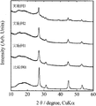
- FIG. 2 is an X-ray diffraction diagram of samples obtained in Examples 1 to 3 and Comparative Example 1.
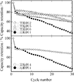
- 6 is a graph showing cycle characteristics of lithium secondary batteries in which the samples obtained in Examples 1 to 3 and Comparative Example 1 are used as a positive electrode active material.
- FIG. 2 is an X-ray diffraction diagram of samples obtained in Examples 2 and 4 to 6 and Comparative Example 1.
- 5 is a graph showing cycle characteristics of lithium secondary batteries in which the samples obtained in Examples 2 and 4 to 6 and Comparative Example 1 are used as a positive electrode active material.
- It is a X-ray-diffraction figure of the sample obtained by Example 7 and Comparative Example 2.
- It is a graph which shows the cycle characteristic of the lithium secondary battery which uses the sample obtained in Example 7 and Comparative Example 2 as a positive electrode active material.
- lithium ion secondary battery is a concept including “metal lithium secondary battery” using metallic lithium as a negative electrode material. Further, in the present disclosure, “lithium ion secondary battery” refers to both “nonaqueous lithium ion secondary battery” using a non-aqueous electrolyte and “all solid lithium ion secondary battery” using a solid electrolyte. means.
- the complex of the present disclosure contains lithium, iron and / or niobium, sulfur and halogen as constituent elements.
- a halogen-containing composite of the present disclosure is a material that exhibits good cycle characteristics while maintaining capacity (particularly discharge capacity), and is particularly useful as an electrode active material application of lithium batteries such as lithium ion secondary batteries is there.
- the addition of halogen is very important in showing good cycle characteristics, and the effect of this halogen is in combination with the high capacity characteristics of the sulfur material to exhibit particularly excellent charge and discharge characteristics.
- Each of the iron-based composite and the niobium-based composite will be described below.
- halogen contained in such a halogen containing complex
- a fluorine, chlorine, a bromine, an iodine etc. are mentioned. Among them, chlorine, bromine, iodine and the like are preferable, bromine and iodine and the like are more preferable, and iodine is particularly preferable, from the viewpoint of particularly excellent cycle characteristics.
- fluorine, chlorine, bromine and the like are preferable, fluorine, chlorine and the like are more preferable, and fluorine is particularly preferable.
- these halogens can be used alone or in combination of two or more.
- the iron-based complex (halogen-containing lithium-iron-sulfur complex) contains lithium, iron, sulfur and halogen as constituent elements, and is subjected to powder X-ray diffraction measurement.
- the lithium sulfide phase which is estimated from the ratio of the peak intensity determined to be derived from the lithium sulfide (Li 2 S) phase among the X-ray diffraction peaks clearly observed in the case of 90 mass% or more
- the crystallite size calculated from the half value width of the diffraction peak based on the (111) plane of Li 2 S obtained by powder X-ray diffraction measurement be 80 nm or less.
- the lower limit value is not particularly limited, but the side reaction with the electrolytic solution and the like increase with the increase of the specific surface area due to the refinement of the crystallite size, so the upper limit is preferably about 10 nm.
- iron atoms and halogen atoms which are additive elements are disposed in the lithium sulfide crystal lattice to form iron-sulfur bond and halogen-sulfur bond, and the iron is contained to the inside.
- the conductivity is imparted, the utilization factor of the electrode (particularly, the utilization factor of the positive electrode) is high, and the high capacity characteristics inherent to lithium sulfide can be exhibited more sufficiently.
- the presence of free sulfur because iron atoms and halogen atoms as additive elements are disposed in the lithium sulfide crystal lattice to form iron-sulfur bonds and halogen-sulfur bonds.
- the main phase preferably comprises lithium sulfide.
- the amount of lithium sulfide phase present is the ratio of peak intensity determined to be derived from lithium sulfide (Li 2 S) phase based on the clearly observed X-ray diffraction peak when powder X-ray diffraction measurement is performed 90 mass% or more is preferable, and, as for the abundance ratio of the said lithium sulfide phase estimated from these, 95 mass% or more is more preferable.
- the upper limit of 100% by mass is most preferable.
- iron-based complex halogen-containing lithium-iron-sulfur complex
- impurities raw material compounds described later, etc.
- impurities up to 10% by mass (especially 5% by mass) other than crystal phase of lithium sulfide ) May be contained, and if it is this kind of impurity content, the influence on the charge and discharge characteristics is limited.
- the iron-based complex (halogen-containing lithium-iron-sulfur complex) of the present disclosure it is preferable that a metastable phase in which iron atoms and halogen atoms are introduced into a lithium sulfide crystal lattice is stabilized. Since a halogen-containing lithium-iron-sulfur complex which is a metastable phase is stably present, it is preferable to be composed of crystallites of submicron or less. More specifically, the crystallite size of the iron-based complex (halogen-containing lithium-iron-sulfur complex) of the present disclosure is preferably 80 nm or less, and more preferably 60 nm or less (particularly 1 to 50 nm).
- the lower limit value is not particularly limited, but the side reaction with the electrolytic solution and the like increase with the increase of the specific surface area due to the refinement of the crystallite size, so the upper limit is preferably about 10 nm.
- the iron-based composite (halogen-containing lithium-iron-sulfur composite) of the present disclosure is produced by a production method including mechanical milling as in the production method described later, crystallites are produced by mechanical milling. It is possible to miniaturize.
- the crystallite size of the iron-based composite of the present disclosure is determined from the half value width of the (111) plane-based diffraction peak showing the highest peak of lithium sulfide peak observed as the main phase in powder X-ray diffraction measurement. It is a value calculated based on Scherrer's equation.
- the abundance ratio of each element in the iron-based complex (halogen-containing lithium-iron-sulfur complex) of the present disclosure is not particularly limited, but iron-sulfur bond and halogen- to the extent that free sulfur does not occur.
- iron-sulfur bond and halogen- to the extent that free sulfur does not occur.
- There is an amount of iron and halogen sufficient to form a sulfur bond an amount of lithium with a theoretical capacity of 600 mAh / g or more estimated from the amount of lithium contained, and an amount of iron sufficient to ensure conductivity.
- the total lithium content of the iron-based composite (halogen-containing lithium-iron-sulfur composite) of the present invention (halogen-containing lithium-iron-sulfur composite) is 100 at.
- halogen-containing The amount is preferably 1 to 8 at% (especially 1 to 6 at%). In the case of using a plurality of atoms as the halogen, it is preferable to adjust so that the total amount thereof is within the above range.
- the iron atom and the halogen atom are disposed in the lithium sulfide crystal lattice to form an iron-sulfur bond and a halogen-sulfur bond.
- the metastable phase iron and the halogen-containing lithium sulfide are easily formed into submicron particles, and the metastable phase iron and the halogen-containing lithium sulfide can be stabilized.
- carbon is contained as a constituent element in addition to the above lithium, iron, sulfur and halogen in order to further improve the conductivity. You can also.
- the carbon content in the complex is 1 to 25 atomic percent (especially 5 to 20 atomic percent), and the total of lithium, iron, sulfur and halogen is 75 to 99 atomic percent (especially 80 to 95 atomic percent) It is preferable to
- the iron-based complex (halogen-containing lithium-iron-sulfur complex) of the present disclosure having such features has an iron-sulfur bond and iron atoms and halogen atoms as additional elements disposed in a lithium sulfide crystal lattice. Since it forms a halogen-sulfur bond and contains almost no free sulfur, it is suppressed that it dissolves in the electrolytic solution as lithium polysulfide at the time of lithium desorption / insertion and is moved / deposited on the negative electrode, and the cycle characteristics are good. .
- the niobium-based composite (halogen-containing lithium-niobium-sulfur composite) contains lithium, niobium, sulfur and halogen as constituent elements, and has a cubic rock salt type crystal structure. It is preferable to have
- the cubic rock salt type crystal structure possessed by the niobium-based composite of such a configuration is a space group:
- Li 3 NbS 4 cubic cubic rock salt type consisting of only a crystalline phase having unit cells similar to Li 3 NbS 4 from the viewpoint of capacity and cycle characteristics. It is preferably a crystalline structure.
- the niobium-based composite of the present disclosure only needs to contain the above-mentioned cubic rock salt type crystal structure, and other rock salt types having different cation distribution (eg, monoclinic layered rock salt type, hexagonal layered rock salt type) , Spinel type, etc.) may be used.
- the niobium-based composite of the present disclosure may be a material having only the above-mentioned cubic rock salt type crystal structure.
- the material which consists only of the crystal structure of said cubic crystal rock salt type tends to be formed in the niobium system complex obtained.
- the present disclosure by having a cubic rock salt type crystal structure, when used as an electrode active material for lithium batteries such as lithium ion secondary batteries, it is possible to maintain good capacity (particularly discharge capacity). It is preferable that the abundance ratio of the cubic rock salt type crystal structure is high because it is a material having cycle characteristics.
- the niobium-based composite of the present disclosure has another rock salt type structure (monoclinic layered rock salt type, hexagonal layered rock salt type, spinel type, etc.) having the same composition but different cation distribution
- the ratio with the crystal structure of cubic rock salt type is usually 1 to 99% by mass (especially 10 to 95% by mass), assuming that the total amount of the niobium-based composite of the present disclosure is 100% by mass.
- the crystal phase of other rock salt type structures is 1 to 99 mass% (especially 5 to 90 mass%, further 10) ⁇ 50% by mass) is preferable.
- the proportion of each of these crystal structures can be estimated, for example, using Rietveld analysis of powder X-ray diffraction patterns or the like (for example, F. Izumi and T. Ikeda, Mater Sci. Forum, 321, 198 (2000). reference).
- the abundance ratio of each element in the niobium-based composite (halogen-containing lithium-niobium-sulfur composite) of the present disclosure is not particularly limited, but the amount of niobium and halogen are present to such an extent that free sulfur is not generated. It is preferable that there be an amount of lithium having a theoretical capacity of 600 mAh / g or more estimated from the amount of lithium contained, and an amount of niobium sufficient to ensure conductivity. From such a point of view, the total content of lithium, niobium, sulfur and halogen in the formed niobium-based composite (halogen-containing lithium-niobium-sulfur composite) of the present invention is 100 at.
- halogen-containing The amount is preferably 1 to 10 at% (especially 1 to 8 at%). In the case of using a plurality of atoms as the halogen, it is preferable to adjust so that the total amount thereof is within the above range.
- Carbon can be included as a constituent element in the niobium-based composite (halogen-containing lithium-niobium-sulfur composite) of the present disclosure.
- the content of carbon in the composite is 1 to 20 atomic percent (especially 5 to 15 atomic percent), and the total of lithium, niobium, sulfur and halogen is 80 to 99 atomic percent (especially 85 to 95 atomic percent) It is preferable to
- the iron-based complex (halogen-containing lithium-iron-sulfur complex) of the present disclosure is not particularly limited, but a lithium-containing compound It can be obtained by subjecting a mixture containing an iron-containing compound, a sulfur-containing compound and a halogen-containing compound to a current sintering process and a mechanical milling process. According to this method, it is possible to obtain a composite in a state in which the particles are miniaturized and the metastable phase in which iron atoms and halogen atoms are incorporated into the lithium sulfide phase is stabilized. The method will be specifically described below.
- lithium-containing compounds, iron-containing compounds, sulfur-containing compounds, and halogen-containing compounds are not particularly limited, and four or more types each containing one element of lithium, iron, sulfur and halogen are included.
- Compounds of different types may be mixed and used, or compounds which simultaneously contain two or more of lithium, iron, sulfur and halogen may be used as part or all of the raw materials.
- these raw material compounds are compounds which do not contain metal elements other than lithium, iron and halogen. Moreover, about elements other than each element of lithium, iron, sulfur, and a halogen contained in a raw material compound, what remove
- lithium-containing compound lithium sulfide (Li 2 S), lithium carbonate (Li 2 CO 3)
- lithium hydroxide (LiOH) lithium hydroxide
- iron-containing compound metal Iron (Fe), iron sulfide (FeS, FeS 2 etc.), iron sulfate (FeSO 4 ), etc.
- sulfur (S), lithium sulfide (Li 2 S), benzothiophene (C 8 H) as a sulfur containing compound 6 S), iron sulfide (FeS, FeS 2 ), etc., and fluorine (F 2 ), lithium fluoride (LiF), iron fluoride (FeF 2 ), etc. can be illustrated as the fluorine-containing compound, chlorine-containing compounds And chlorine (Cl 2 ), lithium chloride (LiCl), iron chloride (FeCl 2 ), etc.
- bromine-containing compound bromine (Br 2 ), lithium bromide (LiBr), iron bromide (FeBr 2 ) etc.
- lithium sulfide (Li 2 S) which consists of only the constituent elements of the iron-based complex (halogen-containing lithium-iron-sulfur complex) of the present disclosure, which is a product, and can be reacted with a small number of raw materials.
- iron sulfide (FeS) and lithium halide lithium fluoride (LiF), lithium chloride (LiCl), lithium bromide (LiBr), lithium iodide (LiI), etc.
- LiF iron sulfide
- LiCl lithium chloride
- LiBr lithium bromide
- LiI lithium iodide
- the average particle diameter of the raw material compound is determined as the particle diameter at which the cumulative frequency becomes 50% by particle size distribution measurement by a dry laser diffraction / scattering equation.
- the average particle size may be controlled by using a raw material compound having a large particle size and pulverizing with a mortar or the like.
- the mixing ratio of the raw material consisting of the lithium-containing compound, the iron-containing compound, the sulfur-containing compound and the halogen-containing compound is not particularly limited, but the iron-based complex of the present disclosure (halogen-containing lithium-iron- In the sulfur complex), there is an amount of iron and halogen sufficient to form an iron-sulfur bond and a halogen-sulfur bond to the extent that free sulfur does not occur, and the theoretical capacity estimated from the amount of lithium is 600 mAh / g or more It is preferable that there is only an amount of lithium and an amount of iron sufficient to ensure conductivity.
- the total content of lithium, iron, sulfur and halogen in the iron-based complex (halogen-containing lithium-iron-sulfur complex) of the present disclosure to be formed is 100 at. 70 atomic percent (especially 50 to 60 atomic percent), iron content 3 to 10 atomic percent (especially 5 to 8 atomic percent), sulfur content 20 to 45 atomic percent (especially 25 to 40 atomic percent), halogen-containing
- the amount is preferably 1 to 8 at% (especially 1 to 6 at%).
- the mixing ratio of the raw material compounds may be such that the ratio of each element contained in the raw material compound is the same as the ratio of each element in the target complex.
- the ratio of each element contained in the raw material compound is the ratio of each element in the target complex
- Carbon-containing compounds carbon materials such as carbon black, acetylene black, etc.
- the total content of lithium, iron, sulfur, halogen and carbon is 100 atomic%
- the carbon content is 1 to 25 atomic% (particularly 5 to 20 atomic%)
- the total amount of lithium, iron, sulfur and halogen It is preferable to set 75 to 99 atomic percent (particularly 80 to 95 atomic percent).
- the electric current sintering process is preferably performed on a mixture containing a lithium-containing compound, an iron-containing compound, and a sulfur-containing compound.
- a conductive mold conductive container
- a DC pulse current to the conductive mold (conductive container) (discharge plasma Heating of the mold (conductive container) having conductivity by Joule heat occurs by a method called sintering method, pulse current sintering method, plasma activation sintering method, etc., and the type (conductive container) having conductivity
- the raw material mixture in the above is heated, each element diffuses and moves, and an intermediate in which each element is mutually mixed at the atomic level can be suitably prepared.
- the atmosphere at the time of the current sintering process be a non-oxidative atmosphere.
- the current sintering process may be performed under normal pressure, it is preferable to perform the current sintering process under pressure.
- the halogen-containing compound used as the raw material compound may be added at this stage, or may be added at the time of mechanical milling described later, but the material is reduced at the stage of the electric current sintering process (composition changes) It is preferable to add it in the case of the mechanical milling process mentioned later, in order to suppress that.
- a lithium-containing compound as a raw material, an iron-containing compound, a sulfur-containing compound and, if necessary, a raw material mixture containing a halogen-containing compound are preferably filled in a conductive type (conductive container).
- a conductive type conductive container.
- the material of the conductive type is not particularly limited as long as it has conductivity, and for example, other than those made of carbon, iron, iron oxide, aluminum, tungsten carbide, etc., Those formed of a mixture of carbon nitride and / or iron oxide mixed with silicon nitride can also be suitably used.
- the electric current sintering process is preferably performed in a non-oxidizing atmosphere, for example, in an inert gas atmosphere such as argon or nitrogen, or in a reducing atmosphere such as hydrogen.
- the oxygen concentration may be sufficiently low, for example, under a partial pressure of 20 Pa or less (particularly, 1 to 20 Pa).
- the inside of the container can be made non-oxidizing atmosphere.
- the type having conductivity may not be completely sealed, and in the case of using the incompletely sealed container, the container is accommodated in the reaction chamber, and the inside of the reaction chamber is accommodated. It can be a non-oxidative atmosphere. Thereby, it is possible to perform the heating reaction of the above-mentioned raw material mixture in non-oxidizing atmosphere.
- the heating temperature in the current-sintering treatment is generally to further diffuse the constituent elements sufficiently to mix them with one another at the atomic level and to reduce sulfur (free sulfur) which is not bonded to the transition metal and the typical element.
- the temperature range is preferably 400 to 1300 ° C. from the viewpoint of increasing the capacity and suppressing the loss due to volatilization of elements such as lithium, sulfur and halogen to further increase the capacity.
- the time for keeping in the above heating temperature range is preferably 0 to 30 minutes, from the viewpoint of further suppressing the loss due to volatilization of elements such as lithium, sulfur, and halogen and making the capacity higher. If it reaches the range, the current may be stopped immediately (that is, the holding time at the above-mentioned heating temperature may be 0) to cool.
- the pressure applied to the raw material powder is, for example, from the viewpoint of strengthening the mutual contact of the raw material compounds to make the atomic mutual diffusion at the time of heating more sufficient and making the reaction between atoms in the raw material compounds more sufficient. 5 to 60 MPa is preferred, and 10 to 50 MPa is more preferred.
- the apparatus for conducting the electric current sintering is not particularly limited as long as the raw material mixture can be heated, cooled, pressurized and the like, and a current necessary for discharge can be applied.
- a commercially available electric sintering device discharge plasma sintering device
- Such an electric sintering device and its principle are disclosed, for example, in Japanese Patent Application Laid-Open No. 10-251070.
- FIG. 1 shows the model of the current-flow sintering apparatus below.
- the electrical-sintering apparatus used by this invention is not restricted only to the apparatus demonstrated below.
- the electric sintering apparatus 1 shown in FIG. 1 has a sintering die (electron conductive container) 3 and a pair of upper and lower punches 4 and 5 in which a sample 2 is loaded. Punches 4 and 5 are supported by punch electrodes 6 and 7, respectively, and through this punch electrodes 6 and 7, a pulse current is supplied while pressurizing sample 2 loaded in sintering die 3 as required. can do.
- the raw material of the sintering die 3 is not limited, and examples thereof include carbon materials such as graphite.
- the current-carrying portion including the conductive container 3, the current-carrying punches 4 and 5, and the punched electrodes 6 and 7 described above is accommodated in the water-cooled vacuum chamber 8 and the atmosphere in the chamber is an atmosphere. It can be adjusted to a predetermined atmosphere by the control mechanism 15. Therefore, it is preferable to adjust the inside of the chamber to a non-oxidizing atmosphere using the atmosphere control mechanism 15.
- the control device 12 drives and controls the pressure mechanism 13, the pulse power source 11, the atmosphere control mechanism 15, the water cooling mechanisms 16 and 10, and the temperature measurement device 17.
- the control device 12 drives the pressure mechanism 13 so that the punch electrodes 6 and 7 press the raw material mixture at a predetermined pressure.
- the pulse current applied for heating may be, for example, a pulse-shaped direct current (switching on and off) having a pulse width of 2 to 3 milliseconds and a period of about 3 to 300 Hz.
- the specific current value varies depending on the type, size and the like of the conductive mold (conductive container), it is preferable to determine the specific current value so as to be in the above temperature range. For example, in the case of using a graphite mold having an inner diameter of 15 mm, 200 to 1000 A, and in the case of using a graphite mold having an inner diameter of 100 mm, 1000 to 8000 A is preferable.
- the electric current sintering process it is preferable to increase or decrease the current value while monitoring the temperature of the mold material and to control the current value so that the predetermined temperature can be managed.
- the raw material mixture filled in the above-described conductive container 3 can be pressurized through the punch electrodes 6 and 7.
- the mechanical milling method is a method of grinding and mixing raw materials while applying mechanical energy, and according to this method, the raw materials are mechanically mixed by applying mechanical impact and friction to the raw materials and mixing them.
- a metastable phase is likely to be obtained because each compound contained is brought into contact with the surface to be finely divided.
- a metastable halogen-containing lithium-iron-sulfur complex which is difficult to produce only by heat treatment in the current-carrying sintering process, can be refined and stably present. .
- a mechanical milling device for example, a ball mill, a vibration mill, a turbo mill, a disk mill and the like can be used, and among these, a vibration mill is preferable.
- the mechanical milling treatment is preferably performed in a non-oxidizing atmosphere, for example, in an inert gas atmosphere such as argon and nitrogen, or in a reducing atmosphere such as hydrogen in order to further suppress the oxidation of sulfides.
- the oxygen concentration may be sufficiently low, for example, under a partial pressure of 20 Pa or less (particularly, 1 to 20 Pa).
- the temperature at which the mechanical milling treatment is performed is preferably 200 ° C. or less from the viewpoint of easily suppressing volatilization of sulfur and forming a complex having a high content ratio of the target sulfur.
- the mechanical milling time is not particularly limited, but it is preferable to carry out the mechanical milling treatment until the crystallite size of the obtained complex becomes 80 nm or less.
- niobium-based composite (halogen-containing lithium-niobium-sulfur composite) of the present disclosure is not particularly limited, but lithium-containing compounds, niobium-containing compounds, sulfur-containing compounds And the mixture containing the halogen-containing compound can be obtained by subjecting the mixture to mechanical milling. According to this method, particles can be refined to obtain a complex having a cubic rock salt type crystal structure. The method will be specifically described below.
- the types of lithium-containing compounds, niobium-containing compounds, sulfur-containing compounds, and halogen-containing compounds are not particularly limited, and four or more types each containing one element of lithium, niobium, sulfur and halogen are included. Compounds of different types may be mixed and used, or compounds which simultaneously contain two or more of lithium, niobium, sulfur and halogen may be used as part or all of the raw materials.
- these raw material compounds are compounds which do not contain metal elements other than lithium, niobium and halogen. Moreover, about elements other than each element of lithium, niobium, sulfur, and a halogen contained in a raw material compound, what remove
- lithium-containing compound lithium sulfide (Li 2 S), lithium carbonate (Li 2 CO 3)
- lithium hydroxide (LiOH) lithium hydroxide
- a niobium-containing compound metal Examples include niobium (Nb), niobium sulfide (NbS 2 , NbS 3 , Nb 3 S 4 etc.), niobium iodide (NbI 5 ), etc., and sulfur (S) and lithium sulfide (Li 2 S) as sulfur-containing compounds.
- bromine as the bromine containing compound (Br 2), lithium bromide (LiBr), can be exemplified bromide niobium (NbBr 5) or the like
- Ciodine-containing compounds iodine (I 2), lithium iodide (LiI) may be exemplified iodide niobium (NBI 5) or the like.
- lithium sulfide (Li 2 S) which consists of only the constituent elements of the niobium-based composite (halogen-containing lithium-niobium-sulfur composite) of the present disclosure, which is a product, and which can be reacted with a small number of raw materials.
- Niobium sulfide (NbS 2 , NbS 3 , Nb 2 S 3 , Nb 3 S 4 etc.) and lithium halides (lithium fluoride (LiF), lithium chloride (LiCl), lithium bromide (LiBr), lithium iodide ( A combination of LiI) etc is preferred.
- the average particle diameter of the raw material compound is determined as the particle diameter at which the cumulative frequency becomes 50% by particle size distribution measurement by a dry laser diffraction / scattering equation.
- the average particle size may be controlled by using a raw material compound having a large particle size and pulverizing with a mortar or the like.
- the mixing ratio of the raw materials comprising the lithium-containing compound, the niobium-containing compound, the sulfur-containing compound and the halogen-containing compound is not particularly limited, but the niobium-based composite (halogen-containing lithium-niobium- In the sulfur complex), an amount of niobium and a halogen are present to such an extent that free sulfur is not generated, and an amount of lithium having a theoretical capacity of 600 mAh / g or more estimated from the amount of lithium contained is present.
- an amount of niobium is present.
- the total content of lithium, niobium, sulfur and halogen in the niobium-based composite (halogen-containing lithium-niobium-sulfur composite) of the present disclosure to be formed is 100 at. 50 atomic percent (especially 35 to 45 atomic percent), niobium content 5 to 15 atomic percent (especially 7 to 13 atomic percent), sulfur content 30 to 60 atomic percent (especially 35 to 55 atomic percent), halogen-containing The amount is preferably 1 to 10 at% (especially 1 to 8 at%). In the case of using a plurality of atoms as the halogen, it is preferable to adjust so that the total amount thereof is within the above range.
- the mixing ratio of the raw material compounds may be such that the ratio of each element contained in the raw material compound is the same as the ratio of each element in the target complex.
- the ratio of each element contained in the raw material compound is the ratio of each element in the target composite
- Carbon-containing compounds carbon materials such as carbon black, acetylene black, etc.
- the total content of lithium, niobium, sulfur, halogen and carbon is 100 atomic%
- the carbon content is 1 to 20 atomic% (particularly 5 to 15 atomic%)
- the total amount of lithium, niobium, sulfur and halogen It is preferable to set 80 to 99 atomic percent (particularly 85 to 95 atomic percent).
- the mechanical milling method is a method of grinding and mixing raw materials while applying mechanical energy, and according to this method, the raw materials are mechanically mixed by applying mechanical impact and friction to the raw materials and mixing them.
- a metastable phase is likely to be obtained because each compound contained is brought into contact with the surface to be finely divided.
- the metastable halogen-containing lithium-niobium-sulfur complex can be formed to be finely divided and stably present.
- a mechanical milling device for example, a ball mill, a vibration mill, a turbo mill, a disk mill and the like can be used, and among these, a vibration mill is preferable.
- the mechanical milling treatment is preferably performed in a non-oxidizing atmosphere, for example, in an inert gas atmosphere such as argon and nitrogen, or in a reducing atmosphere such as hydrogen in order to further suppress the oxidation of sulfides.
- the oxygen concentration may be sufficiently low, for example, under a partial pressure of 20 Pa or less (particularly, 1 to 20 Pa).
- the temperature at which the mechanical milling treatment is performed is preferably 200 ° C. or less from the viewpoint of easily suppressing volatilization of sulfur and forming a complex having a high content ratio of the target sulfur.
- the mechanical milling time is not particularly limited, but it is preferable to carry out the mechanical milling treatment until the crystallite size of the obtained complex becomes 80 nm or less.
- Lithium Battery makes use of the above-described excellent characteristics to make an electrode active material (especially positive electrode charge) of a lithium battery (particularly a lithium ion secondary battery) such as a lithium primary battery or a lithium ion secondary battery. It can be effectively used as an active material.
- a lithium ion secondary battery is a concept including a lithium secondary battery using lithium metal as a negative electrode.
- the halogen-containing composite of the present disclosure is a material that contains lithium in its structure, it is a material that can perform charge and discharge from charge, and also has excellent cycle characteristics. It is useful as an electrode active material (in particular, a positive electrode active material) for a secondary battery.
- the capacity retention rate after at least 30 cycles in the development stage can be about 60% or more, or the capacity retention rate after 15 cycles can be about 70% or more as cycle characteristics good enough to be used as practical materials.
- the lithium ion secondary battery using the halogen-containing complex of the present disclosure as an electrode active material may be a non-aqueous electrolyte lithium ion secondary battery using a non-aqueous solvent electrolyte as an electrolyte It may be an all solid lithium ion secondary battery using a lithium ion conductive solid electrolyte.
- the structures of the non-aqueous electrolyte lithium ion secondary battery and the all solid lithium ion secondary battery are the same as those of known secondary lithium ions except that the halogen-containing composite of the present disclosure is used as an electrode active material (in particular, positive electrode active material). It can be the same as the battery.
- the basic structure is the same as that of the known non-aqueous electrolyte lithium except that the above-described halogen-containing composite of the present disclosure is used as an electrode active material (particularly positive electrode active material). It can be made similar to the ion secondary battery.
- the above-described halogen-containing composite of the present disclosure is used as a positive electrode active material, and for example, a positive electrode mixture containing the halogen-containing composite of the present disclosure, a conductive material and a binder is aluminum, nickel, stainless steel, carbon cloth, etc.
- the positive electrode current collector of As the conductive material for example, carbon materials such as graphite, cokes, carbon black, and needle-like carbon can be used.
- the halogen-containing composite of the present disclosure is used as the negative electrode active material, conventionally known materials may be used as the positive electrode active material.
- the negative electrode it is possible to use both a material containing lithium and a material not containing lithium.
- a material containing lithium lithium metal, tin, silicon, alloys containing these, silicon oxide, etc. can be used other than graphite, sinter-proof carbon, etc.
- These negative electrode active materials can also be supported on a negative electrode current collector made of aluminum, copper, nickel, stainless steel, carbon or the like, using the above-described conductive material, binder or the like, as necessary.
- the halogen-containing composite of the present disclosure may be used as a negative electrode active material.
- the separator is made of, for example, a polyolefin resin such as polyethylene or polypropylene, a fluorocarbon resin, nylon, an aromatic aramid, an inorganic glass or the like, and a material such as a porous film, a nonwoven fabric or a woven fabric can be used.
- solvents can be used as the solvent for non-aqueous solvent secondary batteries such as carbonates, ethers, nitriles and sulfur-containing compounds.
- the all solid lithium ion secondary battery also has the same structure as that of a known all solid lithium ion secondary battery except that the halogen-containing complex of the present disclosure is used as an electrode active material (in particular, positive electrode active material). can do.
- the lithium ion conductive solid electrolyte for example, a polymer based solid electrolyte such as a polyethylene oxide type polymer compound, a polymer compound containing at least one of a polyorganosiloxane chain and a polyoxyalkylene chain, etc.
- a polymer based solid electrolyte such as a polyethylene oxide type polymer compound, a polymer compound containing at least one of a polyorganosiloxane chain and a polyoxyalkylene chain, etc.
- An organic solid electrolyte, an oxide solid electrolyte, etc. can also be used.
- the halogen-containing composite of the present disclosure is used as a positive electrode active material, and for example, a positive electrode composite including the halogen-containing composite of the present disclosure, a conductive material, a binder, and a solid electrolyte
- the agent can be supported on a positive electrode current collector such as titanium, aluminum, nickel or stainless steel.
- a positive electrode current collector such as titanium, aluminum, nickel or stainless steel.
- carbon materials such as graphite, cokes, carbon black, needle-like carbon, and the like can be used as in the non-aqueous solvent secondary battery.
- the negative electrode it is possible to use both a material containing lithium and a material not containing lithium.
- a material containing lithium lithium metal, tin, silicon, alloys containing these, silicon oxide, etc. can be used other than graphite, sinter-proof carbon, etc.
- These negative electrode active materials can also be supported on a negative electrode current collector made of aluminum, copper, nickel, stainless steel, carbon or the like, using the above-described conductive material, binder or the like, as necessary.
- the halogen-containing composite of the present disclosure may be used as a negative electrode active material.
- the shapes of the non-aqueous electrolyte lithium ion secondary battery and the all-solid-state lithium ion secondary battery are not particularly limited either, and may be cylindrical, square, or the like.
- Example 1 Commercially available lithium sulfide (Li 2 S) (Mitsukazu Chemical model number: MIT000965) and iron sulfide (FeS) (Alfa Aesar model number: 14024) in a glove box under an argon gas atmosphere so that the molar ratio is 4: 1
- the mixture was weighed at a dew point of ⁇ 80 ° C., thoroughly mixed in a mortar, and then filled in a graphite mold having an inner diameter of 15 mm.
- the graphite mold material filled with the raw material was accommodated in a current-flow sinter.
- the current-carrying part including the graphite mold material and the electrode part is housed in the vacuum chamber, and the inside of the chamber is filled with high purity argon gas (about 0.2 ppm oxygen concentration) to atmospheric pressure after vacuum (about 20 Pa) degassing did.
- a pulse current of about 800 A (pulse width 2.5 msec, period 28.6 Hz) was applied to the graphite mold material.
- the vicinity of the graphite mold was heated at a temperature rising rate of about 200 ° C./min, and reached 800 ° C. 4 minutes after the start of the pulse current application. After that, the current application and pressurization were immediately stopped, and natural cooling was performed.
- the graphite jig was transferred to a glove box under an argon gas atmosphere with a dew point of ⁇ 80 ° C., and the reaction product of Li 2 S and FeS was taken out of the mold and crushed in a mortar.
- LiI Lithium iodide
- LiI 1: 0.3
- acetylene black (AB) powder is further added
- the ratio (atomic%) of each element used in the raw material is 56.8 atomic% Li, 6.9 atomic% Fe, S 34.2 atomic%, I 2.1 atomic%, assuming that the total amount of Li, Fe, S and I is 100 atomic%.
- the composition of the raw material base is Li 8.3 FeS 5 I 0.3 ).
- the obtained composite powder is used as a positive electrode material of a lithium secondary battery, lithium metal at the negative electrode, aluminum mesh at the current collector, and LiPF 6 dissolved in ethylene carbonate / dimethyl carbonate mixed solution as electrolyte.
- a charge / discharge test was conducted by starting charging using constant current measurement at a cutoff of 1.0-2.6 V at a current density of 46.7 mA / g.
- the initial discharge capacity is about 630 mAh / g
- the discharge capacity after 30 cycles is about 400 mAh / g
- the discharge capacity after 30 cycles is higher than in Comparative Example 1 (about 290 mAh / g), as shown in FIG.
- the capacity retention ratio (cycle characteristic) with respect to the initial capacity was about 63%, which was significantly improved as compared with the case of Comparative Example 1 (about 36%).
- Example 2 An iodine-containing lithium-iron-sulfur complex was produced in the same manner as in Example 1 except that the molar ratio of the Li 2 S-FeS reactant and lithium iodide (LiI) was changed to 1: 0.5.
- the ratio (atomic%) of each element used in the raw material is 56.7 atomic% of Li, 6.7 atomic% of Fe, 33.3 atomic% of S, 3.3 atomic% of I, where the total of Li, Fe, S and I is 100 atomic%.
- the composition of the raw material base was Li 8.5 FeS 5 I 0.5 ).
- the charge and discharge test was conducted in the same manner as in Example 1 except that this composite powder was used as a positive electrode material of a lithium secondary battery.
- the initial discharge capacity is about 630 mAh / g, and the discharge capacity after 30 cycles is about 450 mAh / g, which is higher than that of Comparative Example 1 (about 290 mAh / g), as shown in FIG.
- the capacity retention rate (cycle characteristics) was about 72%, which was significantly improved as compared with the case of Comparative Example 1 (about 36%).
- Example 3 An iodine-containing lithium-iron-sulfur complex was produced in the same manner as in Example 1 except that the molar ratio of the Li 2 S-FeS reactant to lithium iodide (LiI) was 1: 1.
- the ratio (atomic%) of each element used as the raw material is 56.2 atomic% of Li, 6.3 atomic% of Fe, S 31.2 atomic%, I 6.3 atomic%, where the total amount of Li, Fe, S and I is 100 atomic%. (Raw composition based on Li 9 FeS 5 I).
- the charge and discharge test was conducted in the same manner as in Example 1 except that this composite powder was used as a positive electrode material of a lithium secondary battery.
- the initial discharge capacity is about 500 mAh / g
- the discharge capacity after 30 cycles is about 320 mAh / g, which is higher than in the case of Comparative Example 1 (about 290 mAh / g), and as shown in FIG.
- the capacity retention rate (cycle characteristics) was about 63%, which was significantly improved as compared with the case of Comparative Example 1 (about 36%).
- Example 4 Example 4 was repeated except that lithium bromide (LiBr) was used instead of lithium iodide (LiI) (the molar ratio of Li 2 S—FeS reactant to lithium bromide (LiBr) was 1: 0.5).
- a bromine-containing lithium-iron-sulfur complex was prepared.
- the ratio (atomic%) of each element used in the raw material is 56.7 atomic% of Li, 6.7 atomic% of Fe, 33.3 atomic% of S, 3.3 atomic% of Br, assuming that the total amount of Li, Fe, S and Br is 100 atomic%.
- the composition based on the raw material is Li 8.5 FeS 5 Br 0.5 ).
- the charge and discharge test was conducted in the same manner as in Example 1 except that this composite powder was used as a positive electrode material of a lithium secondary battery.
- the initial discharge capacity is about 670 mAh / g
- the discharge capacity after 30 cycles is about 450 mAh / g
- the discharge capacity after 30 cycles is higher than in Comparative Example 1 (about 290 mAh / g), as shown in FIG.
- the capacity retention ratio (cycle characteristic) with respect to the initial capacity was about 68%, which was significantly improved as compared with the case of Comparative Example 1 (about 36%).
- Example 5 is the same as Example 2 except that lithium chloride (LiCl) is used instead of lithium iodide (LiI) (the molar ratio of Li 2 S—FeS reactant to lithium chloride (LiCl) is 1: 0.5).
- LiI lithium iodide
- LiI lithium iodide
- a chlorine-containing lithium-iron-sulfur complex was prepared.
- the ratio (atomic%) of each element used as the raw material is 56.7 atomic% of Li, 6.7 atomic% of Fe, 33.3 atomic% of S, 3.3 atomic% of Cl, assuming that the total of Li, Fe, S and Cl is 100 atomic%.
- the composition of the raw material base was Li 8.5 FeS 5 Cl 0.5 ).
- the charge and discharge test was conducted in the same manner as in Example 1 except that this composite powder was used as a positive electrode material of a lithium secondary battery.
- the initial discharge capacity is about 690 mAh / g
- the discharge capacity after 30 cycles is about 410 mAh / g
- the discharge capacity after 30 cycles is higher than in Comparative Example 1 (about 290 mAh / g), as shown in FIG.
- the capacity retention ratio (cycle characteristic) with respect to the initial capacity was about 59%, which was significantly improved as compared with the case of Comparative Example 1 (about 36%).
- Lithium fluoride (LiF) is used instead of lithium iodide (LiI) (Molar ratio of Li 2 S—FeS reactant and lithium fluoride (LiF) is 1: 0.5)
- LiI lithium iodide
- a fluorine-containing lithium-iron-sulfur complex was prepared.
- the ratio (atomic%) of each element used as the raw material is 56.7 atomic% of Li, 6.7 atomic% of Fe, 33.3 atomic% of S, 3.3 atomic% of F, assuming that the total of Li, Fe, S and F is 100 atomic%.
- the composition of the raw material base was Li 8.5 FeS 5 F 0.5 ).
- the charge and discharge test was conducted in the same manner as in Example 1 except that this composite powder was used as a positive electrode material of a lithium secondary battery.
- the initial discharge capacity is about 660 mAh / g
- the discharge capacity after 30 cycles is about 400 mAh / g
- the discharge capacity after 30 cycles is higher than in Comparative Example 1 (about 290 mAh / g), as shown in FIG.
- the capacity retention ratio (cycle characteristic) with respect to the initial capacity was about 61%, which was significantly improved as compared with the case of Comparative Example 1 (about 36%).
- Example 2 The charge and discharge test was conducted in the same manner as in Example 1 except that this composite powder was used as a positive electrode material of a lithium secondary battery. Although the initial discharge capacity is relatively high at about 810 mAh / g, the capacity after 30 cycles is about 290 mAh / g, and as shown in FIG. 3, the capacity retention ratio relative to the initial capacity is about 36%, compared to the above example Was a low value.
- Example 7 Li 2 S, Nb 2 S 3 , S and LiI are mixed so as to have a molar ratio of 3: 1: 2: 0.5, placed in a zirconia pot under an argon gas atmosphere, and Li 3 NbS 4 -0.5 by a planetary ball mill method. LiI complex was prepared. The ratio (atomic%) of each element used in the raw material is 38.9 atomic% Li, 11.1 atomic% Nb, S 44.4 atomic%, I 5.6 atomic%, assuming that the total amount of Li, Nb, S and I is 100 atomic%. (The composition of the raw material base was Li 3.5 NbS 4 I 0.5 ). As shown in FIG. 6, in the X-ray diffraction pattern of the obtained sample, a peak attributed to the cubic rock salt type structure was observed, and no other clear peak was observed.
- the obtained composite powder is used as a positive electrode material of a lithium secondary battery, lithium metal at the negative electrode, aluminum mesh at the current collector, and LiPF 6 dissolved in ethylene carbonate / dimethyl carbonate mixed solution as electrolyte.
- the charge and discharge test was performed using this. As a result, as shown in FIG. 7, the capacity retention rate was higher than that in Comparative Example 2 in which no LiI was added.
- the ratio (atomic%) of each element used for the raw material was 37.5 atomic% Li, 12.5 atomic% Nb, and S 50.0 atomic%, assuming that the total amount of Li, Nb and S is 100 atomic%.
- composition Li 3 NbS 4 As shown in FIG. 6, in the X-ray diffraction pattern of the obtained sample, a peak attributed to the cubic rock salt type structure was observed, and no other clear peak was observed.
- Example 7 The charge and discharge test was conducted in the same manner as in Example 7 except that this composite powder was used as a positive electrode material of a lithium secondary battery. As a result, as shown in FIG. 7, the capacity retention rate was lower than in the case of Example 7 in which iodine was added.
- the present invention can be used as an electrode active material exhibiting good characteristics in various storage batteries including lithium batteries and the like.
Landscapes
- Chemical & Material Sciences (AREA)
- Organic Chemistry (AREA)
- Inorganic Chemistry (AREA)
- Engineering & Computer Science (AREA)
- Materials Engineering (AREA)
- Chemical Kinetics & Catalysis (AREA)
- Electrochemistry (AREA)
- General Chemical & Material Sciences (AREA)
- Battery Electrode And Active Subsutance (AREA)
- Inorganic Compounds Of Heavy Metals (AREA)
Abstract
リチウム、鉄及び/又はニオブ、硫黄、並びにハロゲンを構成元素として含む複合体は、リチウム電池用電極活物質として用いられた場合に、良好なサイクル特性を示すようなリチウム電池となる材料である。
Description
本開示は、ハロゲン含有複合体及びその製造方法に関する。
近年の携帯電子機器・ハイブリッド車等の高性能化により、それに用いられる二次電池(特にリチウムイオン二次電池)は益々高容量化が求められるようになっている。現行のリチウムイオン二次電池では負極に比べて正極の高容量化が遅れており、最近盛んに研究開発されている高容量型のLi(Ni,Mn,Co)O2系材料でも250~300mAh/g程度である。
一方、硫黄は理論容量が約1670mAh/gと高く、高容量電極材料の有望な候補の一つである。しかしながら、硫黄単体はリチウムを含有していないので、負極にリチウム又はリチウムを含む合金等を用いなければならず、負極の選択幅が狭いという欠点がある。
これに対して、硫化リチウムはリチウムを含有しているので、負極に黒鉛やシリコン等の合金類を用いることができ、負極の選択幅が飛躍的に広がるとともに、金属リチウムの使用によるデンドライト生成が引き起こす短絡等の危険性を回避することができる。しかしながら、硫化リチウムは、有機電解液を用いた電池系においては、充放電時に多硫化リチウムとして電解液に溶出し、それが負極に移動して偏析するという問題があり(例えば、非特許文献1等参照)、硫化リチウムが本来的に持つ高容量を発現させるのが難しい。そのため、硫化リチウムを正極に用いた電池の性能向上には、溶出した多硫化リチウムを正極内に保持しておくような正極層の設計や、負極を保護するような電解液の工夫等の対策が必要となる。
多硫化リチウム溶出を抑制する方法として、Li挿入・脱離反応の際に硫黄原子が遊離しないよう異種元素との結合を形成する方法が考えられる。そのためには、異種元素を硫化リチウムに導入した化合物を作製する必要がある。添加する異種元素としては、絶縁性の硫化リチウムに導電性を付与することのできる遷移金属元素が適しており、例えば、特許文献1及び2に記載の、LixFeySz等の化合物等が挙げられる。このような遷移金属元素の導入による硫黄元素の遊離抑制、及び導電性付与により、硫化リチウムの利用率向上を図ることができるが、サイクル特性向上のためには、繰り返しLi挿入・脱離に伴う構造の可逆性を向上させる必要がある。そのための方策の一つとして、典型元素を導入し、硫黄及び遷移金属と典型元素の間に結合を形成して骨格構造を安定化させる方法が考えられる。複数の異種元素(遷移金属元素、典型元素)を導入した硫化リチウム複合体の例として、リチウム-鉄-リン-硫黄-炭素複合体があり(例えば、特許文献3参照)、段階予備充放電無しで高容量を発現する等の利点は報告されているものの、サイクル特性が向上した例はまだ報告例が無い。上述の携帯電子機器・ハイブリッド車等へ搭載する二次電池としては、高容量と良好なサイクル特性を併せ持つ材料の開発が求められている。
T. Takeuchi, H. Sakaebe, H. Kageyama, H. Senoh, T. Sakai, and K. Tatsumi, J. Power Sources, 195, 2928 (2010).
本開示は、上記した従来技術の現状に鑑みてなされたものであり、その主な目的は、リチウム電池用電極活物質として用いられた場合に、良好なサイクル特性を示すようなリチウム電池となる材料を提供することである。
項1.リチウム、鉄及び/又はニオブ、硫黄、並びにハロゲンを構成元素として含む複合体。
項2.リチウム、鉄、硫黄及びハロゲンを構成元素として含み、
粉末X線回折測定を行った場合に、明確に観測されるX線回折ピークのうち、硫化リチウム(Li2S)相に由来すると判断されるピーク強度の割合から見積もられる前記硫化リチウム相の存在比が90質量%以上であり、且つ、
粉末X線回折測定によって得られたLi2Sの(111)面に基づく回折ピークの半価幅から算出される結晶子サイズが80nm以下である、項1に記載の複合体。
項3.複合体中のリチウム、鉄、硫黄及びハロゲンの総量を100原子%として、リチウム含有量が40~70原子%、鉄含有量が3~10原子%、硫黄含有量が20~45原子%、ハロゲン含有量が1~8原子%である、項2に記載の複合体。
項4.項1~3のいずれか1項に記載の複合体の製造方法であって、
リチウム含有化合物、鉄含有化合物、硫黄含有化合物、及びハロゲン含有化合物を含む混合物に対して、通電焼結処理及びメカニカルミリング処理を施す工程を備える、製造方法。
項5.前記通電焼結処理及びメカニカルミリング処理が、前記リチウム含有化合物、前記鉄含有化合物、及び前記硫黄含有化合物を含む混合物に対して通電焼結処理を行った後に、得られた通電焼結物を前記ハロゲン含有化合物とともにメカニカルミリング処理を施す処理である、項4に記載の製造方法。
項6.前記リチウム含有化合物、鉄含有化合物、及び硫黄含有化合物を含む混合物が、硫化リチウムと硫化鉄との混合物である、項5に記載の製造方法。
項7.前記通電焼結処理及び/又はメカニカルミリング処理が、非酸化性雰囲気下において行われる、項4~6のいずれか1項に記載の製造方法。
項8.前記通電焼結処理及び/又はメカニカルミリング処理が、導電性を有する型内において行われる、項4~7のいずれか1項に記載の製造方法。
項9.前記通電焼結処理及び/又はメカニカルミリング処理が、加圧下に行われる、項4~8のいずれか1項に記載の製造方法。
項10.リチウム、ニオブ、硫黄及びハロゲンを構成元素として含み、立方晶岩塩型の結晶構造を有する、項1に記載の複合体。
項11.複合体中のリチウム、ニオブ、硫黄及びハロゲンの総量を100原子%として、リチウム含有量が30~50原子%、ニオブ含有量が5~15原子%、硫黄含有量が30~60原子%、ハロゲン含有量が1~10原子%である、項10に記載の複合体。
項12.リチウムイオン二次電池の電極活物質用である、項10又は11に記載の複合体。
項13.項1及び10~12のいずれか1項に記載の複合体の製造方法であって、
リチウム含有化合物、ニオブ含有化合物、硫黄含有化合物、及びハロゲン含有化合物を含む混合物に対して、メカニカルミリング処理を施す工程を備える、製造方法。
項14.前記リチウム含有化合物、ニオブ含有化合物、硫黄含有化合物、及びハロゲン含有化合物を含む混合物が、硫化リチウム、硫化ニオブ及びハロゲン化リチウムを含む混合物である、項13に記載の製造方法。
項15.前記メカニカルミリング処理が、非酸化性雰囲気下において行われる、項13又は14に記載の製造方法。
項16.項1~3及び10~12のいずれか1項に記載の複合体を含有する、リチウム電池用電極活物質。
項17.項16に記載のリチウム電池用電極活物質を構成要素として含有する、リチウム電池。
項18.リチウムイオン二次電池である、項17に記載のリチウム電池。
項2.リチウム、鉄、硫黄及びハロゲンを構成元素として含み、
粉末X線回折測定を行った場合に、明確に観測されるX線回折ピークのうち、硫化リチウム(Li2S)相に由来すると判断されるピーク強度の割合から見積もられる前記硫化リチウム相の存在比が90質量%以上であり、且つ、
粉末X線回折測定によって得られたLi2Sの(111)面に基づく回折ピークの半価幅から算出される結晶子サイズが80nm以下である、項1に記載の複合体。
項3.複合体中のリチウム、鉄、硫黄及びハロゲンの総量を100原子%として、リチウム含有量が40~70原子%、鉄含有量が3~10原子%、硫黄含有量が20~45原子%、ハロゲン含有量が1~8原子%である、項2に記載の複合体。
項4.項1~3のいずれか1項に記載の複合体の製造方法であって、
リチウム含有化合物、鉄含有化合物、硫黄含有化合物、及びハロゲン含有化合物を含む混合物に対して、通電焼結処理及びメカニカルミリング処理を施す工程を備える、製造方法。
項5.前記通電焼結処理及びメカニカルミリング処理が、前記リチウム含有化合物、前記鉄含有化合物、及び前記硫黄含有化合物を含む混合物に対して通電焼結処理を行った後に、得られた通電焼結物を前記ハロゲン含有化合物とともにメカニカルミリング処理を施す処理である、項4に記載の製造方法。
項6.前記リチウム含有化合物、鉄含有化合物、及び硫黄含有化合物を含む混合物が、硫化リチウムと硫化鉄との混合物である、項5に記載の製造方法。
項7.前記通電焼結処理及び/又はメカニカルミリング処理が、非酸化性雰囲気下において行われる、項4~6のいずれか1項に記載の製造方法。
項8.前記通電焼結処理及び/又はメカニカルミリング処理が、導電性を有する型内において行われる、項4~7のいずれか1項に記載の製造方法。
項9.前記通電焼結処理及び/又はメカニカルミリング処理が、加圧下に行われる、項4~8のいずれか1項に記載の製造方法。
項10.リチウム、ニオブ、硫黄及びハロゲンを構成元素として含み、立方晶岩塩型の結晶構造を有する、項1に記載の複合体。
項11.複合体中のリチウム、ニオブ、硫黄及びハロゲンの総量を100原子%として、リチウム含有量が30~50原子%、ニオブ含有量が5~15原子%、硫黄含有量が30~60原子%、ハロゲン含有量が1~10原子%である、項10に記載の複合体。
項12.リチウムイオン二次電池の電極活物質用である、項10又は11に記載の複合体。
項13.項1及び10~12のいずれか1項に記載の複合体の製造方法であって、
リチウム含有化合物、ニオブ含有化合物、硫黄含有化合物、及びハロゲン含有化合物を含む混合物に対して、メカニカルミリング処理を施す工程を備える、製造方法。
項14.前記リチウム含有化合物、ニオブ含有化合物、硫黄含有化合物、及びハロゲン含有化合物を含む混合物が、硫化リチウム、硫化ニオブ及びハロゲン化リチウムを含む混合物である、項13に記載の製造方法。
項15.前記メカニカルミリング処理が、非酸化性雰囲気下において行われる、項13又は14に記載の製造方法。
項16.項1~3及び10~12のいずれか1項に記載の複合体を含有する、リチウム電池用電極活物質。
項17.項16に記載のリチウム電池用電極活物質を構成要素として含有する、リチウム電池。
項18.リチウムイオン二次電池である、項17に記載のリチウム電池。
本開示によれば、良好なサイクル特性を示す材料を提供することができる。
本明細書において、数値範囲を「A~B」で表示する場合、A以上B以下を意味する。また、「含有」は、「含む(comprise)」、「実質的にのみからなる(consist essentially of)」及び「のみからなる(consist of)」のいずれも包含する。
本開示において、「リチウムイオン二次電池」とは、負極材料として金属リチウムを用いた「金属リチウム二次電池」も包含する概念である。また、本開示において、「リチウムイオン二次電池」とは、非水電解液を使用した「非水リチウムイオン二次電池」と固体電解質を使用した「全固体リチウムイオン二次電池」の双方を意味する。
1.ハロゲン含有複合体
本開示の複合体は、リチウム、鉄及び/又はニオブ、硫黄、並びにハロゲンを構成元素として含む。このような本開示のハロゲン含有複合体は、容量(特に放電容量)を維持しつつ良好なサイクル特性を示す材料であり、リチウムイオン二次電池等のリチウム電池の電極活物質用途として特に有用である。特に、ハロゲンの添加が良好なサイクル特性を示す上で非常に重要であり、このハロゲンの効果が、硫黄材料が持つ高容量の特性と組み合わさることにより、特に優れた充放電特性を示すことになる。以下、鉄系複合体及びニオブ系複合体のそれぞれについて説明する。
本開示の複合体は、リチウム、鉄及び/又はニオブ、硫黄、並びにハロゲンを構成元素として含む。このような本開示のハロゲン含有複合体は、容量(特に放電容量)を維持しつつ良好なサイクル特性を示す材料であり、リチウムイオン二次電池等のリチウム電池の電極活物質用途として特に有用である。特に、ハロゲンの添加が良好なサイクル特性を示す上で非常に重要であり、このハロゲンの効果が、硫黄材料が持つ高容量の特性と組み合わさることにより、特に優れた充放電特性を示すことになる。以下、鉄系複合体及びニオブ系複合体のそれぞれについて説明する。
このようなハロゲン含有複合体に含有されるハロゲンとしては、特に制限はなく、フッ素、塩素、臭素、ヨウ素等が挙げられる。なかでも、サイクル特性に特に優れる観点からは、塩素、臭素、ヨウ素等が好ましく、臭素、ヨウ素等がより好ましく、ヨウ素が特に好ましい。一方、初期放電容量に特に優れる観点からは、フッ素、塩素、臭素等が好ましく、フッ素、塩素等がより好ましく、フッ素が特に好ましい。これらのバランスを考慮し、これらのハロゲンは、単独で用いることもでき、2種以上を組合せて用いることもできる。
(1-1)鉄系複合体
本開示において、鉄系複合体(ハロゲン含有リチウム-鉄-硫黄複合体)は、リチウム、鉄、硫黄及びハロゲンを構成元素として含み、粉末X線回折測定を行った場合に、明確に観測されるX線回折ピークのうち、硫化リチウム(Li2S)相に由来すると判断されるピーク強度の割合から見積もられる前記硫化リチウム相の存在比が90質量%以上であり、且つ、粉末X線回折測定によって得られたLi2Sの(111)面に基づく回折ピークの半価幅から算出される結晶子サイズが80nm以下であることが好ましい。下限値は特に限定されるものではないが、結晶子サイズの微細化による比表面積の増大に伴い、電解液との副反応等が増加するため、10nm程度までが好ましい。
本開示において、鉄系複合体(ハロゲン含有リチウム-鉄-硫黄複合体)は、リチウム、鉄、硫黄及びハロゲンを構成元素として含み、粉末X線回折測定を行った場合に、明確に観測されるX線回折ピークのうち、硫化リチウム(Li2S)相に由来すると判断されるピーク強度の割合から見積もられる前記硫化リチウム相の存在比が90質量%以上であり、且つ、粉末X線回折測定によって得られたLi2Sの(111)面に基づく回折ピークの半価幅から算出される結晶子サイズが80nm以下であることが好ましい。下限値は特に限定されるものではないが、結晶子サイズの微細化による比表面積の増大に伴い、電解液との副反応等が増加するため、10nm程度までが好ましい。
このような構成の複合体では、添加元素である鉄原子及びハロゲン原子が硫化リチウム結晶格子内に配置して鉄-硫黄結合及びハロゲン-硫黄結合を形成しており、鉄を含むために内部まで導電性が付与されており、電極利用率(特に正極利用率)が高く、硫化リチウムが本来有する高容量の特性をより十分に発揮することができる。
また、このような構成の複合体では、添加元素である鉄原子及びハロゲン原子が硫化リチウム結晶格子内に配置して鉄-硫黄結合及びハロゲン-硫黄結合を形成しているために遊離硫黄の存在がより抑制され、また、リチウムの挿入・脱離時に多硫化リチウムとして電解液に溶出して負極に移動・析出することもより抑制され、特に優れたサイクル特性を発揮することができる。
本開示の鉄系複合体(ハロゲン含有リチウム-鉄-硫黄複合体)は、粉末X線回折測定において、主相が硫化リチウムからなることが好ましい。硫化リチウム相の存在量は、粉末X線回折測定を行った場合に、明確に観測されるX線回折ピークを基準として、硫化リチウム(Li2S)相に由来すると判断されるピーク強度の割合から見積もられる前記硫化リチウム相の存在比は90質量%以上が好ましく、95質量%以上がより好ましい。上限値の100質量%が最も好ましい。なお、本開示の鉄系複合体(ハロゲン含有リチウム-鉄-硫黄複合体)は、硫化リチウムの結晶相以外に少量の不純物(後述の原料化合物等)が10質量%まで(特に5質量%まで)なら含まれていてもよく、この程度の不純物含有量であれば充放電特性に与える影響は限定的である。
また、本開示の鉄系複合体(ハロゲン含有リチウム-鉄-硫黄複合体)は、鉄原子及びハロゲン原子が硫化リチウム結晶格子内に導入された準安定相が安定化されることが好ましい。準安定相であるハロゲン含有リチウム-鉄-硫黄複合体が安定的に存在するため、サブミクロン以下の結晶子からなることが好ましい。より具体的には、本開示の鉄系複合体(ハロゲン含有リチウム-鉄-硫黄複合体)の結晶子サイズは、80nm以下が好ましく、60nm以下(特に1~50nm)がより好ましい。下限値は特に限定されるものではないが、結晶子サイズの微細化による比表面積の増大に伴い、電解液との副反応等が増加するため、10nm程度までが好ましい。後述の製造方法のように、メカニカルミリング処理を含む製造方法により本開示の鉄系複合体(ハロゲン含有リチウム-鉄-硫黄複合体)が製造された場合には、メカニカルミリング処理により、結晶子を微細化することが可能である。なお、本開示の鉄系複合体の結晶子サイズは、粉末X線回折測定において主相として観測される硫化リチウムのピークの最高強度を示す(111)面に基づく回折ピークの半価幅から、Scherrerの式に基づいて算出される値である。
さらに、本開示の鉄系複合体(ハロゲン含有リチウム-鉄-硫黄複合体)における各元素の存在割合については、特に限定的ではないが、遊離硫黄が生じない程度に鉄-硫黄結合及びハロゲン-硫黄結合が形成できるだけの鉄量及びハロゲン量が存在し、含有リチウム量から見積もられる理論容量が600mAh/g以上であるだけのリチウム量が存在し、導電性を確保できるだけの鉄量が存在することが好ましい。このような観点から、形成される本発明の鉄系複合体(ハロゲン含有リチウム-鉄-硫黄複合体)中のリチウム、鉄、硫黄及びハロゲンの総量を100原子%として、リチウム含有量は40~70原子%(特に50~60原子%)、鉄含有量は3~10原子%(特に5~8原子%)、硫黄含有量は20~45原子%(特に25~40原子%)、ハロゲン含有量は1~8原子%(特に1~6原子%)であることが好ましい。なお、ハロゲンとして複数の原子を使用する場合は、その合計量が上記範囲内となるように調整することが好ましい。
なお、リチウム量を理論容量が600mAh/g以上となる量とした理由については、酸化物系の高容量材料Li(Ni,Mn,Co)O2が最大値として300mAh/g×4V= 1200Wh/kgのエネルギー密度を有するため、それと同程度の硫黄系材料(電圧2V)として600mAh/g以上あれば十分と判断したことによる。
この様な状態の本開示の鉄系複合体(ハロゲン含有リチウム-鉄-硫黄複合体)においては、鉄原子及びハロゲン原子は硫化リチウム結晶格子内に配置して鉄-硫黄結合及びハロゲン-硫黄結合を形成しやすく、準安定相である鉄及びハロゲン含有硫化リチウムが形成されてサブミクロンの粒子となりやすく、本来準安定相である鉄及びハロゲン含有硫化リチウムが安定化され得る。
なお、本開示の鉄系複合体(ハロゲン含有リチウム-鉄-硫黄複合体)においては、導電性をより向上させるため、上記リチウム、鉄、硫黄及びハロゲン以外にも、炭素を構成元素として含むこともできる。この場合、複合体中の炭素の含有量は1~25原子%(特に5~20原子%)とし、リチウム、鉄、硫黄及びハロゲンの総量を75~99原子%(特に80~95原子%)とすることが好ましい。
このような特徴を有する本開示の鉄系複合体(ハロゲン含有リチウム-鉄-硫黄複合体)は、添加元素である鉄原子及びハロゲン原子が硫化リチウム結晶格子内に配置して鉄-硫黄結合及びハロゲン-硫黄結合を形成し、遊離硫黄をほとんど含まないため、リチウムの脱離・挿入時に多硫化リチウムとして電解液に溶出して負極に移動・析出することが抑制され、サイクル特性が良好である。さらに、鉄を含むため良好な導電性が付与されており、特に、鉄及びハロゲンが硫化リチウム結晶格子内において鉄-硫黄結合及びハロゲン-硫黄結合を形成していることから、硫化リチウム結晶内部の利用率が向上して、高容量を有する材料となる。
(1-2)ニオブ系複合体
本開示において、ニオブ系複合体(ハロゲン含有リチウム-ニオブ-硫黄複合体)は、リチウム、ニオブ、硫黄及びハロゲンを構成元素として含み、立方晶岩塩型の結晶構造を有することが好ましい。
本開示において、ニオブ系複合体(ハロゲン含有リチウム-ニオブ-硫黄複合体)は、リチウム、ニオブ、硫黄及びハロゲンを構成元素として含み、立方晶岩塩型の結晶構造を有することが好ましい。
このような構成のニオブ系複合体が有する立方晶岩塩型の結晶構造は、空間群:

で属させることができる結晶相であり、具体的には、容量及びサイクル特性の観点から、Li3NbS4に類似する単位胞を有する結晶相のみからなるLi3NbS4型立方晶岩塩型の結晶構造であることが好ましい。
本開示のニオブ系複合体は、上記の立方晶岩塩型の結晶構造を含んでいればよく、陽イオン分布の異なる他の岩塩型構造(例えば、単斜晶層状岩塩型、六方晶層状岩塩型、スピネル型等)の結晶構造を含む混合相であってもよい。また、本開示のニオブ系複合体は、上記の立方晶岩塩型の結晶構造のみからなる材料であってもよい。なお、後述する本開示の製造方法によれば、得られるニオブ系複合体は、上記の立方晶岩塩型の結晶構造のみからなる材料が形成されやすい。
ただし、本開示においては、立方晶岩塩型の結晶構造を有することにより、リチウムイオン二次電池等のリチウム電池用電極活物質に用いた場合に、容量(特に放電容量)を維持しつつ良好なサイクル特性を有する材料であることから、立方晶岩塩型の結晶構造の存在割合は高いことが好ましい。このような観点から、本開示のニオブ系複合体が、同じ組成の陽イオン分布の異なる他の岩塩型構造(単斜晶層状岩塩型、六方晶層状岩塩型、スピネル型等)を有する場合、立方晶岩塩型の結晶構造との割合は、通常、本開示のニオブ系複合体の総量を100質量%として、立方晶岩塩型の結晶構造は1~99質量%(特に10~95質量%、さらに50~90質量%)、他の岩塩型構造(単斜晶層状岩塩型、六方晶層状岩塩型、スピネル型等)の結晶相は1~99質量%(特に5~90質量%、さらに10~50質量%)が好ましい。これら各結晶構造の割合については、例えば、粉末X線回折パターンのRietveld解析等を用いて見積もることができる(例えば、F. Izumi and T. Ikeda, Mater Sci. Forum, 321, 198 (2000).参照)。
さらに、本開示のニオブ系複合体(ハロゲン含有リチウム-ニオブ-硫黄複合体)における各元素の存在割合については、特に限定的ではないが、遊離硫黄が生じない程度にニオブ量及びハロゲン量が存在し、含有リチウム量から見積もられる理論容量が600mAh/g以上であるだけのリチウム量が存在し、導電性を確保できるだけのニオブ量が存在することが好ましい。このような観点から、形成される本発明のニオブ系複合体(ハロゲン含有リチウム-ニオブ-硫黄複合体)中のリチウム、ニオブ、硫黄及びハロゲンの総量を100原子%として、リチウム含有量は30~50原子%(特に35~45原子%)、ニオブ含有量は5~15原子%(特に7~13原子%)、硫黄含有量は30~60原子%(特に35~55原子%)、ハロゲン含有量は1~10原子%(特に1~8原子%)であることが好ましい。なお、ハロゲンとして複数の原子を使用する場合は、その合計量が上記範囲内となるように調整することが好ましい。
なお、リチウム量を理論容量が600mAh/g以上となる量とした理由については、酸化物系の高容量材料Li(Ni,Mn,Co)O2が最大値として300mAh/g×4V= 1200Wh/kgのエネルギー密度を有するため、それと同程度の硫黄系材料(電圧2V)として600mAh/g以上あれば十分と判断したことによる。
なお、本開示のニオブ系複合体(ハロゲン含有リチウム-ニオブ-硫黄複合体)に炭素を構成元素として含むこともできる。この場合、複合体中の炭素の含有量は1~20原子%(特に5~15原子%)とし、リチウム、ニオブ、硫黄及びハロゲンの総量を80~99原子%(特に85~95原子%)とすることが好ましい。
2.ハロゲン含有複合体の製造方法
(2-1)ハロゲン含有鉄系複合体の製造方法
本開示の鉄系複合体(ハロゲン含有リチウム-鉄-硫黄複合体)は、特に制限されないが、リチウム含有化合物、鉄含有化合物、硫黄含有化合物及びハロゲン含有化合物を含む混合物に対して、通電焼結処理及びメカニカルミリング処理を施すことによって得ることができる。この方法によれば、粒子が微細化されて、鉄原子及びハロゲン原子が硫化リチウム相内に取り込まれた準安定相が安定化された状態の複合体を得ることができる。以下、この方法について具体的に説明する。
(2-1)ハロゲン含有鉄系複合体の製造方法
本開示の鉄系複合体(ハロゲン含有リチウム-鉄-硫黄複合体)は、特に制限されないが、リチウム含有化合物、鉄含有化合物、硫黄含有化合物及びハロゲン含有化合物を含む混合物に対して、通電焼結処理及びメカニカルミリング処理を施すことによって得ることができる。この方法によれば、粒子が微細化されて、鉄原子及びハロゲン原子が硫化リチウム相内に取り込まれた準安定相が安定化された状態の複合体を得ることができる。以下、この方法について具体的に説明する。
[2-1-1]原料粉末
本開示では、原料として、リチウム含有化合物、鉄含有化合物、硫黄含有化合物、及びハロゲン含有化合物を用いる。
本開示では、原料として、リチウム含有化合物、鉄含有化合物、硫黄含有化合物、及びハロゲン含有化合物を用いる。
リチウム含有化合物、鉄含有化合物、硫黄含有化合物、及びハロゲン含有化合物の各化合物の種類については特に限定的ではなく、リチウム、鉄、硫黄及びハロゲンの各元素を1種類ずつ含む4種類又はそれ以上の種類の化合物を混合して用いてもよく、あるいは、リチウム、鉄、硫黄及びハロゲンの内の2種類又はそれ以上の元素を同時に含む化合物を原料の一部又は全部として用いてもよい。
これらの原料化合物は、リチウム、鉄及びハロゲン以外の金属元素を含まない化合物であることが好ましい。また、原料化合物中に含まれるリチウム、鉄、硫黄及びハロゲンの各元素以外の元素については、後述する熱処理(好ましくは非酸化性雰囲気下での熱処理)により離脱・揮発していくものが好ましい。
この様な原料化合物の具体例としては、リチウム含有化合物として、硫化リチウム(Li2S)、炭酸リチウム(Li2CO3)、水酸化リチウム(LiOH)等を例示でき、鉄含有化合物として、金属鉄(Fe)、硫化鉄(FeS、FeS2等)、硫酸鉄(FeSO4)等を例示でき、硫黄含有化合物として、硫黄(S)、硫化リチウム(Li2S)、ベンゾチオフェン(C8H6S)、硫化鉄(FeS、FeS2)等を例示でき、フッ素含有化合物として、フッ素(F2)、フッ化リチウム(LiF)、フッ化鉄(FeF2)等を例示でき、塩素含有化合物として、塩素(Cl2)、塩化リチウム(LiCl)、塩化鉄(FeCl2)等を例示でき、臭素含有化合物として、臭素(Br2)、臭化リチウム(LiBr)、臭化鉄(FeBr2)等を例示でき、ヨウ素含有化合物として、ヨウ素(I2)、ヨウ化リチウム(LiI)、ヨウ化鉄(FeI2)等を例示できる。この中で、特に生成物である本開示の鉄系複合体(ハロゲン含有リチウム-鉄-硫黄複合体)の構成元素のみからなり、少ない原料数で反応させることのできる硫化リチウム(Li2S)、硫化鉄(FeS)及びハロゲン化リチウム(フッ化リチウム(LiF)、塩化リチウム(LiCl)、臭化リチウム(LiBr)、ヨウ化リチウム(LiI)等)の組合せが好ましい。
これら原料化合物の形状については特に限定はないが、平均粒径0.1~100μmの粉末状であることが好ましい。原料化合物の平均粒径は、乾式のレーザー回折・散乱式による粒度分布測定で、累積度数が50%となる粒径として求める。なお、粒径の大きな原料化合物を使用し、乳鉢等で粉砕することにより、平均粒径を制御してもよい。
リチウム含有化合物、鉄含有化合物、硫黄含有化合物及びハロゲン含有化合物からなる原料の混合割合については、特に限定的ではないが、最終生成物である本開示の鉄系複合体(ハロゲン含有リチウム-鉄-硫黄複合体)において、遊離硫黄が生じない程度に鉄-硫黄結合及びハロゲン-硫黄結合が形成できるだけの鉄量及びハロゲン量が存在し、含有リチウム量から見積もられる理論容量が600mAh/g以上であるだけのリチウム量が存在し、導電性を確保できるだけの鉄量が存在することが好ましい。このような観点から、形成される本開示の鉄系複合体(ハロゲン含有リチウム-鉄-硫黄複合体)中のリチウム、鉄、硫黄及びハロゲンの総量を100原子%として、リチウム含有量は40~70原子%(特に50~60原子%)、鉄含有量は3~10原子%(特に5~8原子%)、硫黄含有量は20~45原子%(特に25~40原子%)、ハロゲン含有量は1~8原子%(特に1~6原子%)であることが好ましい。なお、ハロゲンとして複数の原子を使用する場合は、その合計量が上記範囲内となるように調整することが好ましい。原料化合物の混合比率については、原料化合物に含まれる各元素の比率が、目的とする複合体中の各元素の比率と同一となるようにすればよい。
なお、本開示の鉄系複合体(ハロゲン含有リチウム-鉄-硫黄複合体)に炭素を含ませる場合、原料化合物中に含まれる各元素の比率が、目的とする複合体中の各元素の比率と同一となるように、炭素含有化合物(カーボンブラック、アセチレンブラック等の炭素材料等)を使用することもできる。具体的には、リチウム、鉄、硫黄、ハロゲン及び炭素の総量を100原子%として、炭素含有量は1~25原子%(特に5~20原子%)とし、リチウム、鉄、硫黄及びハロゲンの総量を75~99原子%(特に80~95原子%)とすることが好ましい。
[2-1-2]製造方法
本開示の製造方法においては、上記原料化合物を用いて、リチウム含有化合物、鉄含有化合物、硫黄含有化合物及びハロゲン含有化合物を含む混合物を得た後に、通電焼結処理及びメカニカルミリング処理を施す。通電焼結処理及びメカニカルミリング処理の順序については、特に制限されるわけではないが、まず通電焼結処理を行い、次いで、メカニカルミリング処理を施すことが好ましい。
本開示の製造方法においては、上記原料化合物を用いて、リチウム含有化合物、鉄含有化合物、硫黄含有化合物及びハロゲン含有化合物を含む混合物を得た後に、通電焼結処理及びメカニカルミリング処理を施す。通電焼結処理及びメカニカルミリング処理の順序については、特に制限されるわけではないが、まず通電焼結処理を行い、次いで、メカニカルミリング処理を施すことが好ましい。
(i)通電焼結処理
本開示では、まず、通電焼結処理として、リチウム含有化合物、鉄含有化合物、及び硫黄含有化合物を含む混合物に、通電焼結処理を施すことが好ましい。具体的には、上記した原料混合物を、導電性を有する型(導電性容器)に充填し、該導電性を有する型(導電性容器)に、好ましくは直流パルス電流を通電すること(放電プラズマ焼結法、パルス通電焼結法、プラズマ活性化焼結法等と呼ばれる方法)により、ジュール熱による導電性を有する型(導電性容器)の加熱が起こり、導電性を有する型(導電性容器)内の原料混合物が加熱されて、各元素が拡散移動し、原子レベルで各元素が相互に混合した中間体を好適に作製することができる。この通電焼結処理の際の雰囲気は、非酸化性雰囲気下とすることが好ましい。また、常圧下に通電焼結処理を施してもよいが、加圧下に通電焼結処理を施すことが好ましい。原料化合物として用いるハロゲン含有化合物は、この段階で添加してもよく、後述するメカニカルミリング処理の際に添加してもよいが、通電焼結処理の段階で材料が還元する(組成が変化する)ことをより抑制するため、後述するメカニカルミリング処理の際に添加することが好ましい。
本開示では、まず、通電焼結処理として、リチウム含有化合物、鉄含有化合物、及び硫黄含有化合物を含む混合物に、通電焼結処理を施すことが好ましい。具体的には、上記した原料混合物を、導電性を有する型(導電性容器)に充填し、該導電性を有する型(導電性容器)に、好ましくは直流パルス電流を通電すること(放電プラズマ焼結法、パルス通電焼結法、プラズマ活性化焼結法等と呼ばれる方法)により、ジュール熱による導電性を有する型(導電性容器)の加熱が起こり、導電性を有する型(導電性容器)内の原料混合物が加熱されて、各元素が拡散移動し、原子レベルで各元素が相互に混合した中間体を好適に作製することができる。この通電焼結処理の際の雰囲気は、非酸化性雰囲気下とすることが好ましい。また、常圧下に通電焼結処理を施してもよいが、加圧下に通電焼結処理を施すことが好ましい。原料化合物として用いるハロゲン含有化合物は、この段階で添加してもよく、後述するメカニカルミリング処理の際に添加してもよいが、通電焼結処理の段階で材料が還元する(組成が変化する)ことをより抑制するため、後述するメカニカルミリング処理の際に添加することが好ましい。
具体的な方法としては、導電性を有する型(導電性容器)に原料とするリチウム含有化合物、鉄含有化合物、硫黄含有化合物、及び必要に応じてハロゲン含有化合物を含む原料混合物を充填し、好ましくは非酸化性雰囲気下において、加圧しながらパルス状の(ON-OFFをスイッチングする)直流電流を通電することが好ましい。
導電性を有する型(導電性容器)の材質としては、導電性を有するものであれば特に限定されず、例えば、炭素、鉄、酸化鉄、アルミニウム、タングステンカーバイド等から形成されているものの他、炭素及び/又は酸化鉄に窒化珪素を混合した混合物等から形成されているものも好適に使用することができる。
通電焼結処理は、硫化物の酸化をより抑制するため、非酸化性雰囲気下、例えば、アルゴン、窒素等の不活性ガス雰囲気下、水素等の還元雰囲気下等で行うことが好ましい。また、酸素濃度が十分に低い減圧状態、例えば、酸素分圧が、20Pa以下(特に1~20Pa)の減圧下としてもよい。
具体的な処理としては、導電性を有する型(導電性容器)として十分な密閉状態を確保できる容器を用いる場合には、該容器内を非酸化性雰囲気とすることができる。また、導電性を有する型(導電性容器)は完全な密閉状態でなくてもよく、不完全な密閉状態の容器を用いる場合には、該容器を反応室内に収容して、該反応室内を非酸化性雰囲気とすることができる。これにより、上記した原料混合物の加熱反応を非酸化性雰囲気下で行うことが可能である。この場合、例えば、反応室内を0.01MPa以上(特に0.05~0.2MPa)の不活性ガス雰囲気、還元性ガス雰囲気等とすることが好ましい。
導電性を有する型(導電性容器)に上記した原料混合物を充填した状態で直流パルス電流を印加することにより、ジュール熱による導電性容器の加熱が起こり、容器内の原料が加熱されて出発原料同士が反応して、各原子が相互に混合した中間体が形成され得る。この方法では、30分以下という短時間で目的とする中間体を製造できるので、揮発し易いリチウム、硫黄、ハロゲン等の欠損が少なく、原料混合比とほとんど同じ組成比の中間体を得ることができる。
通電焼結処理における加熱温度は、通常、各構成元素をより十分に相互拡散させてより原子レベルで相互に混合させるとともに、遷移金属及び典型元素と結合しない硫黄(遊離硫黄)をより低減してより高容量とするとともに、リチウム、硫黄、ハロゲン等の元素の揮発による欠損をより抑制してより高容量とする観点から、400~1300℃の温度範囲とすることが好ましい。上記した加熱温度範囲に保持する時間については、リチウム、硫黄、ハロゲン等の元素の揮発による欠損をより抑制してより高容量とする観点から、0~30分とすることが好ましく、上記した温度範囲に到達すれば、直ちに通電を停止して(つまり、上記した加熱温度における保持時間を0として)放冷してもよい。
原料粉末を加圧する際の圧力としては、原料化合物同士の接触をより強くして加熱時の原子相互拡散をより十分にし、原料化合物における原子相互間の反応をより十分とする観点から、例えば、5~60MPaが好ましく、10~50MPaがより好ましい。
通電焼結を行う装置としては、原料混合物を加熱、冷却、加圧等することが可能であり、放電に必要な電流を印加できるものであれば特に限定されない。例えば、市販の通電焼結装置(放電プラズマ焼結装置)を使用できる。このような通電焼結装置及びその原理は、例えば、特開平10-251070号公報等に開示されている。
以下に通電焼結装置の模式図を示した図1を参考にしながら、本発明の通電焼結工程の具体例を説明する。なお、本発明で使用する通電焼結装置は、以下に説明する装置のみに限られない。
図1に示す通電焼結装置1においては、試料2が装填される焼結ダイ(電子伝導性容器)3と上下一対のパンチ4及び5とを有する。パンチ4及び5は、それぞれパンチ電極6及び7に支持されており、このパンチ電極6及び7を介して、焼結ダイ3に装填された試料2に必要に応じて加圧しながらパルス電流を供給することができる。焼結ダイ3の素材は限定されず、例えば、黒鉛等の炭素材料が挙げられる。
図1に示す通電焼結装置では、上記した導電性容器3、通電用パンチ4及び5、パンチ電極6及び7を含む通電部は、水冷真空チャンバー8に収容されており、チャンバー内は、雰囲気制御機構15による所定の雰囲気に調整することができる。したがって、雰囲気制御機構15を利用して、チャンバー内を非酸化性雰囲気に調整することが好ましい。
制御装置12は、加圧機構13、パルス電源11、雰囲気制御機構15、水冷却機構16及び10、並びに温度計測装置17を駆動制御する。制御装置12は加圧機構13を駆動し、パンチ電極6及び7が所定の圧力で原料混合物を加圧するよう構成されている。
加熱のために印加するパルス電流は、例えばパルス幅2~3ミリ秒で、周期は3~300Hz程度のパルス状の(ON-OFFをスイッチングする)直流電流を用いることができる。具体的な電流値は導電性を有する型(導電性容器)の種類、大きさ等により異なるが、上記した温度範囲となるように、具体的な電流値を決めることが好ましい。例えば、内径15mmの黒鉛型材を用いた場合には200~1000A、内径100mmの黒鉛型材を用いた場合には1000~8000Aが好適である。通電焼結処理時は、型材温度をモニターしながら電流値を増減させ、所定の温度を管理できるように電流値を制御することが好ましい。
原料混合物を加圧した状態とするためには、例えば、上記した導電性容器3に充填した原料混合物をパンチ電極6及び7を介して加圧することができる。
(ii)メカニカルミリング処理
上記した通電焼結処理で得られた中間体を、メカニカルミリング処理を施し、混合、粉砕及び反応させることによって、本開示の鉄系複合体(ハロゲン含有リチウム-鉄-硫黄複合体)を得ることができる。通電焼結工程で用いた原料に、所定量のハロゲン含有化合物が含まれていない場合には、メカニカルミリング処理を施す前に、中間体とハロゲン含有化合物とを混合した後にメカニカルミリング処理を施すことができる。
上記した通電焼結処理で得られた中間体を、メカニカルミリング処理を施し、混合、粉砕及び反応させることによって、本開示の鉄系複合体(ハロゲン含有リチウム-鉄-硫黄複合体)を得ることができる。通電焼結工程で用いた原料に、所定量のハロゲン含有化合物が含まれていない場合には、メカニカルミリング処理を施す前に、中間体とハロゲン含有化合物とを混合した後にメカニカルミリング処理を施すことができる。
メカニカルミリング法は、機械的エネルギーを付与しながら原料を摩砕混合し反応させる方法であり、この方法によれば、原料に機械的な衝撃や摩擦を与えて摩砕混合することによって、原料に含まれる各化合物が激しく接触して微細化されるため、準安定相が得られやすい。本開示では、上記したメカニカルミリング処理により、通電焼結工程における熱処理だけでは作製が困難な準安定ハロゲン含有リチウム-鉄-硫黄複合体を形成しつつ、微細化して安定的に存在させることができる。
メカニカルミリング装置としては、例えば、ボールミル、振動ミル、ターボミル、ディスクミル等を用いることができ、なかでも振動ミルが好ましい。
メカニカルミリング処理は、硫化物の酸化をより抑制するため、非酸化性雰囲気下、例えば、アルゴン、窒素等の不活性ガス雰囲気下、水素等の還元雰囲気下等で行うことが好ましい。また、酸素濃度が十分に低い減圧状態、例えば、酸素分圧が、20Pa以下(特に1~20Pa)の減圧下としてもよい。
メカニカルミリング処理を行う際の温度については、硫黄の揮発をより抑制し、目的とする硫黄の含有比率が高い複合体を形成しやすい観点から、200℃以下の温度が好ましい。
メカニカルミリング時間については、特に限定的ではないが、得られる複合体の結晶子サイズが、80nm以下となるまでメカニカルミリング処理を行うことが好ましい。
(2-2)ハロゲン含有ニオブ系複合体の製造方法
本開示のニオブ系複合体(ハロゲン含有リチウム-ニオブ-硫黄複合体)は、特に制限されないが、リチウム含有化合物、ニオブ含有化合物、硫黄含有化合物及びハロゲン含有化合物を含む混合物に対して、メカニカルミリング処理を施すことによって得ることができる。この方法によれば、粒子が微細化されて、立方晶岩塩型の結晶構造を有する複合体を得ることができる。以下、この方法について具体的に説明する。
本開示のニオブ系複合体(ハロゲン含有リチウム-ニオブ-硫黄複合体)は、特に制限されないが、リチウム含有化合物、ニオブ含有化合物、硫黄含有化合物及びハロゲン含有化合物を含む混合物に対して、メカニカルミリング処理を施すことによって得ることができる。この方法によれば、粒子が微細化されて、立方晶岩塩型の結晶構造を有する複合体を得ることができる。以下、この方法について具体的に説明する。
[2-2-1]原料粉末
本開示では、原料として、リチウム含有化合物、ニオブ含有化合物、硫黄含有化合物、及びハロゲン含有化合物を用いる。
本開示では、原料として、リチウム含有化合物、ニオブ含有化合物、硫黄含有化合物、及びハロゲン含有化合物を用いる。
リチウム含有化合物、ニオブ含有化合物、硫黄含有化合物、及びハロゲン含有化合物の各化合物の種類については特に限定的ではなく、リチウム、ニオブ、硫黄及びハロゲンの各元素を1種類ずつ含む4種類又はそれ以上の種類の化合物を混合して用いてもよく、あるいは、リチウム、ニオブ、硫黄及びハロゲンの内の2種類又はそれ以上の元素を同時に含む化合物を原料の一部又は全部として用いてもよい。
これらの原料化合物は、リチウム、ニオブ及びハロゲン以外の金属元素を含まない化合物であることが好ましい。また、原料化合物中に含まれるリチウム、ニオブ、硫黄及びハロゲンの各元素以外の元素については、ミリング条件で離脱・揮発していくものが好ましい。
この様な原料化合物の具体例としては、リチウム含有化合物として、硫化リチウム(Li2S)、炭酸リチウム(Li2CO3)、水酸化リチウム(LiOH)等を例示でき、ニオブ含有化合物として、金属ニオブ(Nb)、硫化ニオブ(NbS2、NbS3、Nb3S4等)、ヨウ化ニオブ(NbI 5)等を例示でき、硫黄含有化合物として、硫黄(S)、硫化リチウム(Li2S)、ベンゾチオフェン(C8H6S)、硫化ニオブ(NbS2、NbS3、Nb2S3、Nb3S4等)等を例示でき、フッ素含有化合物として、フッ素(F2)、フッ化リチウム(LiF)、フッ化ニオブ(NbF5)等を例示でき、塩素含有化合物として、塩素(Cl2)、塩化リチウム(LiCl)、塩化ニオブ(NbCl5)等を例示でき、臭素含有化合物として、臭素(Br2)、臭化リチウム(LiBr)、臭化ニオブ(NbBr5)等を例示でき、ヨウ素含有化合物として、ヨウ素(I2)、ヨウ化リチウム(LiI)、ヨウ化ニオブ(NbI5)等を例示できる。この中で、特に生成物である本開示のニオブ系複合体(ハロゲン含有リチウム-ニオブ-硫黄複合体)の構成元素のみからなり、少ない原料数で反応させることのできる硫化リチウム(Li2S)、硫化ニオブ(NbS2、NbS3、Nb2S3、Nb3S4等)及びハロゲン化リチウム(フッ化リチウム(LiF)、塩化リチウム(LiCl)、臭化リチウム(LiBr)、ヨウ化リチウム(LiI)等)の組合せが好ましい。
これら原料化合物の形状については特に限定はないが、平均粒径0.1~100μmの粉末状であることが好ましい。原料化合物の平均粒径は、乾式のレーザー回折・散乱式による粒度分布測定で、累積度数が50%となる粒径として求める。なお、粒径の大きな原料化合物を使用し、乳鉢等で粉砕することにより、平均粒径を制御してもよい。
リチウム含有化合物、ニオブ含有化合物、硫黄含有化合物及びハロゲン含有化合物からなる原料の混合割合については、特に限定的ではないが、最終生成物である本開示のニオブ系複合体(ハロゲン含有リチウム-ニオブ-硫黄複合体)において、遊離硫黄が生じない程度にニオブ量及びハロゲン量が存在し、含有リチウム量から見積もられる理論容量が600mAh/g以上であるだけのリチウム量が存在し、導電性を確保できるだけのニオブ量が存在することが好ましい。このような観点から、形成される本開示のニオブ系複合体(ハロゲン含有リチウム-ニオブ-硫黄複合体)中のリチウム、ニオブ、硫黄及びハロゲンの総量を100原子%として、リチウム含有量は30~50原子%(特に35~45原子%)、ニオブ含有量は5~15原子%(特に7~13原子%)、硫黄含有量は30~60原子%(特に35~55原子%)、ハロゲン含有量は1~10原子%(特に1~8原子%)であることが好ましい。なお、ハロゲンとして複数の原子を使用する場合は、その合計量が上記範囲内となるように調整することが好ましい。原料化合物の混合比率については、原料化合物に含まれる各元素の比率が、目的とする複合体中の各元素の比率と同一となるようにすればよい。
なお、本開示のニオブ系複合体(ハロゲン含有リチウム-ニオブ-硫黄複合体)に炭素を含ませる場合、原料化合物中に含まれる各元素の比率が、目的とする複合体中の各元素の比率と同一となるように、炭素含有化合物(カーボンブラック、アセチレンブラック等の炭素材料等)を使用することもできる。具体的には、リチウム、ニオブ、硫黄、ハロゲン及び炭素の総量を100原子%として、炭素含有量は1~20原子%(特に5~15原子%)とし、リチウム、ニオブ、硫黄及びハロゲンの総量を80~99原子%(特に85~95原子%)とすることが好ましい。
[2-2-2]製造方法
本開示の製造方法においては、上記原料化合物を用いて、リチウム含有化合物、ニオブ含有化合物、硫黄含有化合物及びハロゲン含有化合物を含む混合物を得た後に、メカニカルミリング処理を施す。これにより、原料化合物を混合、粉砕及び反応させることによって、本開示のニオブ系複合体(ハロゲン含有リチウム-ニオブ-硫黄複合体)を得ることができる。
本開示の製造方法においては、上記原料化合物を用いて、リチウム含有化合物、ニオブ含有化合物、硫黄含有化合物及びハロゲン含有化合物を含む混合物を得た後に、メカニカルミリング処理を施す。これにより、原料化合物を混合、粉砕及び反応させることによって、本開示のニオブ系複合体(ハロゲン含有リチウム-ニオブ-硫黄複合体)を得ることができる。
メカニカルミリング法は、機械的エネルギーを付与しながら原料を摩砕混合し反応させる方法であり、この方法によれば、原料に機械的な衝撃や摩擦を与えて摩砕混合することによって、原料に含まれる各化合物が激しく接触して微細化されるため、準安定相が得られやすい。本開示では、上記したメカニカルミリング処理により、準安定ハロゲン含有リチウム-ニオブ-硫黄複合体を形成しつつ、微細化して安定的に存在させることができる。
メカニカルミリング装置としては、例えば、ボールミル、振動ミル、ターボミル、ディスクミル等を用いることができ、なかでも振動ミルが好ましい。
メカニカルミリング処理は、硫化物の酸化をより抑制するため、非酸化性雰囲気下、例えば、アルゴン、窒素等の不活性ガス雰囲気下、水素等の還元雰囲気下等で行うことが好ましい。また、酸素濃度が十分に低い減圧状態、例えば、酸素分圧が、20Pa以下(特に1~20Pa)の減圧下としてもよい。
メカニカルミリング処理を行う際の温度については、硫黄の揮発をより抑制し、目的とする硫黄の含有比率が高い複合体を形成しやすい観点から、200℃以下の温度が好ましい。
メカニカルミリング時間については、特に限定的ではないが、得られる複合体の結晶子サイズが、80nm以下となるまでメカニカルミリング処理を行うことが好ましい。
3.リチウム電池
本開示のハロゲン含有複合体は、上記した優れた特性を利用して、リチウム一次電池、リチウムイオン二次電池等のリチウム電池(特にリチウムイオン二次電池)の電極活物質(特に正極電活物質)として有効に利用できる。なお、本開示において、リチウムイオン二次電池とは、負極としてリチウム金属を用いたリチウム二次電池も包含する概念である。特に、本開示のハロゲン含有複合体は、構造中にリチウムを含有する材料であるため、充電から充放電を行うことができる材料であり、しかも、優れたサイクル特性を有することから、リチウムイオン二次電池用の電極活物質(特に正極活物質)として有用である。特に実用材料として供しうる程度に良好なサイクル特性として、開発段階で少なくとも30サイクル後の容量維持率が60%程度以上、あるいは15サイクル後の容量維持率が70%程度以上を示すものとし得る。本開示のハロゲン含有複合体を電極活物質(特に正極活物質)として使用するリチウムイオン二次電池は、電解質として非水溶媒系電解液を用いる非水電解質リチウムイオン二次電池であってもよく、リチウムイオン伝導性固体電解質を用いる全固体型リチウムイオン二次電池であってもよい。
本開示のハロゲン含有複合体は、上記した優れた特性を利用して、リチウム一次電池、リチウムイオン二次電池等のリチウム電池(特にリチウムイオン二次電池)の電極活物質(特に正極電活物質)として有効に利用できる。なお、本開示において、リチウムイオン二次電池とは、負極としてリチウム金属を用いたリチウム二次電池も包含する概念である。特に、本開示のハロゲン含有複合体は、構造中にリチウムを含有する材料であるため、充電から充放電を行うことができる材料であり、しかも、優れたサイクル特性を有することから、リチウムイオン二次電池用の電極活物質(特に正極活物質)として有用である。特に実用材料として供しうる程度に良好なサイクル特性として、開発段階で少なくとも30サイクル後の容量維持率が60%程度以上、あるいは15サイクル後の容量維持率が70%程度以上を示すものとし得る。本開示のハロゲン含有複合体を電極活物質(特に正極活物質)として使用するリチウムイオン二次電池は、電解質として非水溶媒系電解液を用いる非水電解質リチウムイオン二次電池であってもよく、リチウムイオン伝導性固体電解質を用いる全固体型リチウムイオン二次電池であってもよい。
非水電解質リチウムイオン二次電池及び全固体型リチウムイオン二次電池の構造は、本開示のハロゲン含有複合体を電極活物質(特に正極活物質)として用いること以外は、公知のリチウムイオン二次電池と同様とすることができる。
例えば、非水電解質リチウムイオン二次電池については、上記した本開示のハロゲン含有複合体を電極活物質(特に正極活物質)として使用する他は、基本的な構造は、公知の非水電解質リチウムイオン二次電池と同様とすることができる。
正極については、上記した本開示のハロゲン含有複合体を正極活物質として用い、例えば、本開示のハロゲン含有複合体と導電材とバインダーとを含む正極合剤をアルミニウム、ニッケル、ステンレス、カーボンクロス等の正極集電体に担持させることができる。導電材としては、例えば、黒鉛、コークス類、カーボンブラック、針状カーボン等の炭素材料を用いることができる。また、負極活物質として本開示のハロゲン含有複合体を使用する場合には、正極活物質としては従来から公知の材料を使用してもよい。
負極としては、リチウムを含有する材料とリチウムを含有しない材料共に用いることが可能である。例えば、黒鉛、難焼結性炭素等の他、リチウム金属、スズ、シリコン及びこれらを含む合金等や、酸化ケイ素等を用いることができる。これらの負極活物質についても、必要に応じて、上記した導電材、バインダー等を用いて、アルミニウム、銅、ニッケル、ステンレス、カーボン等からなる負極集電体に担持させることができる。また、負極活物質として本開示のハロゲン含有複合体を使用してもよい。
セパレータとしては、例えば、ポリエチレン、ポリプロピレン等のポリオレフィン樹脂、フッ素樹脂、ナイロン、芳香族アラミド、無機ガラス等の材質からなり、多孔質膜、不織布、織布等の形態の材料を用いることができる。
非水電解質の溶媒としては、カーボネート、エーテル、ニトリル、含硫黄化合物等の非水溶媒系二次電池の溶媒として公知の溶媒を用いることができる。
また、全固体型リチウムイオン二次電池についても、本開示のハロゲン含有複合体を電極活物質(特に正極活物質)として用いる以外は、公知の全固体型リチウムイオン二次電池と同様の構造とすることができる。
この場合、リチウムイオン電導性固体電解質としては、例えば、ポリエチレンオキサイド系の高分子化合物、ポリオルガノシロキサン鎖及びポリオキシアルキレン鎖の少なくとも一種を含む高分子化合物等のポリマー系固体電解質等の他、硫化物系固体電解質、酸化物系固体電解質等も用いることができる。
全固体型リチウムイオン二次電池の正極については、例えば、本開示のハロゲン含有複合体を正極活物質として用い、例えば、本開示のハロゲン含有複合体、導電材、バインダー、固体電解質を含む正極合剤をチタン、アルミニウム、ニッケル、ステンレス等の正極集電体に担持させることができる。導電材については、非水溶媒系二次電池と同様に、例えば、黒鉛、コークス類、カーボンブラック、針状カーボン等の炭素材料を用いることができる。
負極としては、リチウムを含有する材料とリチウムを含有しない材料共に用いることが可能である。例えば、黒鉛、難焼結性炭素等の他、リチウム金属、スズ、シリコン及びこれらを含む合金等や、酸化ケイ素等を用いることができる。これらの負極活物質についても、必要に応じて、上記した導電材、バインダー等を用いて、アルミニウム、銅、ニッケル、ステンレス、カーボン等からなる負極集電体に担持させることができる。また、負極活物質として本開示のハロゲン含有複合体を使用してもよい。
非水電解質リチウムイオン二次電池、及び全固体型リチウムイオン二次電池の形状についても特に限定はなく、円筒型、角型等のいずれであってもよい。
以上、本開示について説明したが、上記の説明は特定の実施形態のみに限定することを意図するものではなく、各種説明は任意の組合せで採用することが可能である。
以下に実施例及び比較例を示して本発明を具体的に説明する。ただし、本発明は、以下に示す実施例のみに制限されないことは言うまでもない。
実施例1
市販の硫化リチウム(Li2S)(三津和化学 型番:MIT000965)と硫化鉄(FeS)(Alfa Aesar 型番:14024)を、モル比が4: 1となるよう、アルゴンガス雰囲気のグローブボックス内(露点-80℃)で秤量し、乳鉢で充分に混合後、内径15mmの黒鉛型材に充填した。
市販の硫化リチウム(Li2S)(三津和化学 型番:MIT000965)と硫化鉄(FeS)(Alfa Aesar 型番:14024)を、モル比が4: 1となるよう、アルゴンガス雰囲気のグローブボックス内(露点-80℃)で秤量し、乳鉢で充分に混合後、内径15mmの黒鉛型材に充填した。
次いで、原料を充填した黒鉛型材を通電焼結機に収容した。黒鉛型材及び電極部分を含む通電部分については、真空チャンバー内に収容されており、チャンバー内は、真空(約20Pa)脱気後、高純度アルゴンガス(酸素濃度約0.2ppm)を大気圧まで充填した。
その後、黒鉛型材に約800Aのパルス電流(パルス幅2.5ミリ秒、周期28.6Hz)を印加した。黒鉛型材近傍は約200℃/分の昇温速度で加熱され、パルス電流印加開始4分後に800℃に到達した。その後、直ちに電流印加及び加圧を停止して自然放冷した。
室温まで冷却後、黒鉛治具を露点-80℃のアルゴンガス雰囲気のグローブボックスに移し、Li2S とFeSの反応物を型材から取り出し、乳鉢で粉砕した。これにヨウ化リチウム(LiI)を、Li2S-FeS反応物: LiI= 1: 0.3のモル比となるよう混合し、更にアセチレンブラック(AB)粉末を、Li2S-FeS反応物+LiI: AB= 9: 1の質量比となるよう混合し、乳鉢で充分に混合した後、アルゴンガス雰囲気下でジルコニア製ポットに入れ、伊藤製作所製振動カップミル(型式MC-4A)を用い、メカニカルミリング法により8時間処理した。なお、原料に用いた各元素の比率(原子%)は、Li、Fe、S及びIの総量を100原子%として、Li 56.8原子%、Fe 6.9原子%、S 34.2原子%、I 2.1原子%であった(原料ベースの組成はLi8.3FeS5I0.3)。
得られた試料のX線回折パターンは、図2に示す通り、主相として硫化リチウム由来のピークが認められ、それ以外には明瞭なピークは認められなかった。また、硫化リチウムの(111)面に基づく回折ピークの半価幅から見積もった結晶子サイズは約35nmであった。以上から、本手法により、主相が硫化リチウムであり、その結晶子サイズが80nm以下であるヨウ素含有リチウム-鉄-硫黄複合体が作製できた。
得られた複合体粉末をリチウム二次電池の正極材料として用い、負極にリチウム金属、集電体にアルミニウムメッシュ、電解液としてLiPF6をエチレンカルボネート/ジメチルカルボネート混合液に溶解させたものを用いて、電流密度46.7mA/gにおいて、カットオフ1.0-2.6Vにおける定電流測定で充電開始により充放電試験を行った。
初期放電容量は約630mAh/gに対して、30サイクル後の放電容量が約400mAh/gと、30サイクル後の放電容量が比較例1の場合(約290mAh/g)に比べて高く、図3に示す通り、初期容量に対する容量維持率(サイクル特性)が約63%と、比較例1の場合(約36%)に比べて著しく向上した。
以上の結果から、本開示で採用する条件下において、ヨウ素含有リチウム-鉄-硫黄複合体を作製することにより、サイクル特性の向上した電極材料が得られることが確認できた。
実施例2
Li2S-FeS反応物とヨウ化リチウム(LiI)のモル比を1: 0.5とする以外は、実施例1と同様にして、ヨウ素含有リチウム-鉄-硫黄複合体を作製した。なお、原料に用いた各元素の比率(原子%)は、Li、Fe、S及びIの総量を100原子%として、Li 56.7原子%、Fe 6.7原子%、S 33.3原子%、I 3.3原子%であった(原料ベースの組成はLi8.5FeS5I0.5)。
Li2S-FeS反応物とヨウ化リチウム(LiI)のモル比を1: 0.5とする以外は、実施例1と同様にして、ヨウ素含有リチウム-鉄-硫黄複合体を作製した。なお、原料に用いた各元素の比率(原子%)は、Li、Fe、S及びIの総量を100原子%として、Li 56.7原子%、Fe 6.7原子%、S 33.3原子%、I 3.3原子%であった(原料ベースの組成はLi8.5FeS5I0.5)。
得られた試料のX線回折パターンは、図2に示す通り、主相として硫化リチウム由来のピークが認められ、それ以外には明瞭なピークは認められなかった。また、硫化リチウムの(111)面に基づく回折ピークの半価幅から見積もった結晶子サイズは約34nmであった。以上から、本手法により、主相が硫化リチウムであり、その結晶子サイズが80nm以下であるヨウ素含有リチウム-鉄-硫黄複合体が作製できた。
この複合体粉末をリチウム二次電池の正極材料として使用すること以外は実施例1と全く同様にして充放電試験を行った。初期放電容量は約630mAh/gに対して、30サイクル後の放電容量が約450mAh/gと、比較例1の場合(約290mAh/g)に比べて高く、図3に示す通り、初期容量に対する容量維持率(サイクル特性)が約72%と、比較例1の場合(約36%)に比べて著しく向上した。
以上の結果から、本発明で採用する条件下において、ヨウ素含有リチウム-鉄-硫黄複合体を作製することにより、サイクル特性の向上した電極材料が得られることが確認できた。
実施例3
Li2S-FeS反応物とヨウ化リチウム(LiI)のモル比を1: 1とする以外は、実施例1と同様にして、ヨウ素含有リチウム-鉄-硫黄複合体を作製した。なお、原料に用いた各元素の比率(原子%)は、Li、Fe、S及びIの総量を100原子%として、Li 56.2原子%、Fe 6.3原子%、S 31.2原子%、I 6.3原子%であった(原料ベースの組成はLi9FeS5I)。
Li2S-FeS反応物とヨウ化リチウム(LiI)のモル比を1: 1とする以外は、実施例1と同様にして、ヨウ素含有リチウム-鉄-硫黄複合体を作製した。なお、原料に用いた各元素の比率(原子%)は、Li、Fe、S及びIの総量を100原子%として、Li 56.2原子%、Fe 6.3原子%、S 31.2原子%、I 6.3原子%であった(原料ベースの組成はLi9FeS5I)。
得られた試料のX線回折パターンは、図2に示す通り、主相として硫化リチウム由来のピークが認められ、それ以外にはFeSのピークが少量の不純物として認められた。Rietveld解析により見積もられたFePの存在比(質量%)は約1%であった(すなわち、Li2Sの存在比は約99質量%であった)。また、硫化リチウムの(111)面に基づく回折ピークの半価幅から見積もった結晶子サイズは約43nmであった。以上から、本手法により、主相が硫化リチウムであり、その結晶子サイズが80nm以下であるヨウ素含有リチウム-鉄-硫黄複合体が作製できた。
この複合体粉末をリチウム二次電池の正極材料として使用すること以外は実施例1と全く同様にして充放電試験を行った。初期放電容量は約500mAh/gに対して、30サイクル後の放電容量が約320mAh/gと、比較例1の場合(約290mAh/g)に比べて高く、図3に示す通り、初期容量に対する容量維持率(サイクル特性)が約63%と、比較例1の場合(約36%)に比べて著しく向上した。
以上の結果から、本発明で採用する条件下において、ヨウ素含有リチウム-鉄-硫黄複合体を作製することにより、サイクル特性の向上した電極材料が得られることが確認できた。
実施例4
ヨウ化リチウム(LiI)の代わりに臭化リチウム(LiBr)を使用する(Li2S-FeS反応物と臭化リチウム(LiBr)のモル比を1: 0.5とする)以外は、実施例2と同様にして、臭素含有リチウム-鉄-硫黄複合体を作製した。なお、原料に用いた各元素の比率(原子%)は、Li、Fe、S及びBrの総量を100原子%として、Li 56.7原子%、Fe 6.7原子%、S 33.3原子%、Br 3.3原子%であった(原料ベースの組成はLi8.5FeS5Br0.5)。
ヨウ化リチウム(LiI)の代わりに臭化リチウム(LiBr)を使用する(Li2S-FeS反応物と臭化リチウム(LiBr)のモル比を1: 0.5とする)以外は、実施例2と同様にして、臭素含有リチウム-鉄-硫黄複合体を作製した。なお、原料に用いた各元素の比率(原子%)は、Li、Fe、S及びBrの総量を100原子%として、Li 56.7原子%、Fe 6.7原子%、S 33.3原子%、Br 3.3原子%であった(原料ベースの組成はLi8.5FeS5Br0.5)。
得られた試料のX線回折パターンは、図4に示す通り、主相として硫化リチウム由来のピークが認められ、それ以外には明瞭なピークは認められなかった。また、硫化リチウムの(111)面に基づく回折ピークの半価幅から見積もった結晶子サイズは約27nmであった。以上から、本手法により、主相が硫化リチウムであり、その結晶子サイズが80nm以下である臭素含有リチウム-鉄-硫黄複合体が作製できた。
この複合体粉末をリチウム二次電池の正極材料として使用すること以外は実施例1と全く同様にして充放電試験を行った。初期放電容量は約670mAh/gに対して、30サイクル後の放電容量が約450mAh/gと、30サイクル後の放電容量が比較例1の場合(約290mAh/g)に比べて高く、図5に示す通り、初期容量に対する容量維持率(サイクル特性)が約68%と、比較例1の場合(約36%)に比べて著しく向上した。
以上の結果から、本開示で採用する条件下において、臭素含有リチウム-鉄-硫黄複合体を作製することにより、サイクル特性の向上した電極材料が得られることが確認できた。
実施例5
ヨウ化リチウム(LiI)の代わりに塩化リチウム(LiCl)を使用する(Li2S-FeS反応物と塩化リチウム(LiCl)のモル比を1: 0.5とする)以外は、実施例2と同様にして、塩素含有リチウム-鉄-硫黄複合体を作製した。なお、原料に用いた各元素の比率(原子%)は、Li、Fe、S及びClの総量を100原子%として、Li 56.7原子%、Fe 6.7原子%、S 33.3原子%、Cl 3.3原子%であった(原料ベースの組成はLi8.5FeS5Cl0.5)。
ヨウ化リチウム(LiI)の代わりに塩化リチウム(LiCl)を使用する(Li2S-FeS反応物と塩化リチウム(LiCl)のモル比を1: 0.5とする)以外は、実施例2と同様にして、塩素含有リチウム-鉄-硫黄複合体を作製した。なお、原料に用いた各元素の比率(原子%)は、Li、Fe、S及びClの総量を100原子%として、Li 56.7原子%、Fe 6.7原子%、S 33.3原子%、Cl 3.3原子%であった(原料ベースの組成はLi8.5FeS5Cl0.5)。
得られた試料のX線回折パターンは、図4に示す通り、主相として硫化リチウム由来のピークが認められ、それ以外には明瞭なピークは認められなかった。また、硫化リチウムの(111)面に基づく回折ピークの半価幅から見積もった結晶子サイズは約29nmであった。以上から、本手法により、主相が硫化リチウムであり、その結晶子サイズが80nm以下である塩素含有リチウム-鉄-硫黄複合体が作製できた。
この複合体粉末をリチウム二次電池の正極材料として使用すること以外は実施例1と全く同様にして充放電試験を行った。初期放電容量は約690mAh/gに対して、30サイクル後の放電容量が約410mAh/gと、30サイクル後の放電容量が比較例1の場合(約290mAh/g)に比べて高く、図5に示す通り、初期容量に対する容量維持率(サイクル特性)が約59%と、比較例1の場合(約36%)に比べて著しく向上した。
以上の結果から、本開示で採用する条件下において、塩素含有リチウム-鉄-硫黄複合体を作製することにより、サイクル特性の向上した電極材料が得られることが確認できた。
実施例6
ヨウ化リチウム(LiI)の代わりにフッ化リチウム(LiF)を使用する(Li2S-FeS反応物とフッ化リチウム(LiF)のモル比を1: 0.5とする)以外は、実施例2と同様にして、フッ素含有リチウム-鉄-硫黄複合体を作製した。なお、原料に用いた各元素の比率(原子%)は、Li、Fe、S及びFの総量を100原子%として、Li 56.7原子%、Fe 6.7原子%、S 33.3原子%、F 3.3原子%であった(原料ベースの組成はLi8.5FeS5F0.5)。
ヨウ化リチウム(LiI)の代わりにフッ化リチウム(LiF)を使用する(Li2S-FeS反応物とフッ化リチウム(LiF)のモル比を1: 0.5とする)以外は、実施例2と同様にして、フッ素含有リチウム-鉄-硫黄複合体を作製した。なお、原料に用いた各元素の比率(原子%)は、Li、Fe、S及びFの総量を100原子%として、Li 56.7原子%、Fe 6.7原子%、S 33.3原子%、F 3.3原子%であった(原料ベースの組成はLi8.5FeS5F0.5)。
得られた試料のX線回折パターンは、図4に示す通り、主相として硫化リチウム由来のピークが認められ、それ以外には明瞭なピークは認められなかった。また、硫化リチウムの(111)面に基づく回折ピークの半価幅から見積もった結晶子サイズは約28nmであった。以上から、本手法により、主相が硫化リチウムであり、その結晶子サイズが80nm以下であるフッ素含有リチウム-鉄-硫黄複合体が作製できた。
この複合体粉末をリチウム二次電池の正極材料として使用すること以外は実施例1と全く同様にして充放電試験を行った。初期放電容量は約660mAh/gに対して、30サイクル後の放電容量が約400mAh/gと、30サイクル後の放電容量が比較例1の場合(約290mAh/g)に比べて高く、図5に示す通り、初期容量に対する容量維持率(サイクル特性)が約61%と、比較例1の場合(約36%)に比べて著しく向上した。
以上の結果から、本開示で採用する条件下において、フッ素含有リチウム-鉄-硫黄複合体を作製することにより、サイクル特性の向上した電極材料が得られることが確認できた。
比較例1
実施例1で作製したLi2S-FeS反応物とAB粉末を、Li2S-FeS反応物: AB= 9: 1の質量比となるよう混合し、乳鉢で充分に混合した後、アルゴンガス雰囲気下でジルコニア製ポットに入れ、伊藤製作所製振動カップミル(型式MC-4A)を用い、メカニカルミリング法により8時間処理した。なお、原料に用いた各元素の比率(原子%)は、Li、Fe及びSの総量を100原子%として、Li 57.1原子%、Fe 7.2原子%、S 35.7原子%であった(原料ベースの組成はLi8FeS5)。
実施例1で作製したLi2S-FeS反応物とAB粉末を、Li2S-FeS反応物: AB= 9: 1の質量比となるよう混合し、乳鉢で充分に混合した後、アルゴンガス雰囲気下でジルコニア製ポットに入れ、伊藤製作所製振動カップミル(型式MC-4A)を用い、メカニカルミリング法により8時間処理した。なお、原料に用いた各元素の比率(原子%)は、Li、Fe及びSの総量を100原子%として、Li 57.1原子%、Fe 7.2原子%、S 35.7原子%であった(原料ベースの組成はLi8FeS5)。
得られた試料のX線回折パターンは、図2に示す通り、主相として硫化リチウム由来のピークが認められ、それ以外には明瞭なピークは認められなかった。また、硫化リチウムの(111)面に基づく回折ピークの半価幅から見積もった結晶子サイズは約29nmであった。以上から、本手法により、主相が硫化リチウムであり、その結晶子サイズが80nm以下であるリチウム-鉄-硫黄複合体を作製した。
この複合体粉末をリチウム二次電池の正極材料として使用すること以外は実施例1と全く同様にして充放電試験を行った。初期放電容量は約810mAh/gと比較的高いものの、30サイクル後の容量は約290mAh/gと、図3に示す通り、初期容量に対する容量維持率は約36%で、上記の実施例に比べて低い値であった。
以上の結果から、ハロゲンを含有しないリチウム-鉄-硫黄複合体では、硫化リチウムを主相として結晶子サイズが80nm以下の複合体が作製できるものの、リチウム二次電池の正極材料として用いた場合、良好なサイクル特性が得られないことが分かった。
実施例7
Li2S、Nb2S3、S及びLiIを3: 1: 2: 0.5のモル比となるよう混合し、アルゴンガス雰囲気下でジルコニア製ポットに入れ、遊星ボールミル法によりLi3NbS4-0.5LiI複合体を作製した。なお、原料に用いた各元素の比率(原子%)は、Li、Nb、S及びIの総量を100原子%として、Li 38.9原子%、Nb 11.1原子%、S 44.4原子%、I 5.6原子%であった(原料ベースの組成はLi3.5NbS4I0.5)。得られた試料のX線回折パターンは、図6に示す通り、立方晶岩塩型構造に帰属されるピークが認められ、それ以外には明瞭なピークは認められなかった。
Li2S、Nb2S3、S及びLiIを3: 1: 2: 0.5のモル比となるよう混合し、アルゴンガス雰囲気下でジルコニア製ポットに入れ、遊星ボールミル法によりLi3NbS4-0.5LiI複合体を作製した。なお、原料に用いた各元素の比率(原子%)は、Li、Nb、S及びIの総量を100原子%として、Li 38.9原子%、Nb 11.1原子%、S 44.4原子%、I 5.6原子%であった(原料ベースの組成はLi3.5NbS4I0.5)。得られた試料のX線回折パターンは、図6に示す通り、立方晶岩塩型構造に帰属されるピークが認められ、それ以外には明瞭なピークは認められなかった。
得られた複合体粉末をリチウム二次電池の正極材料として用い、負極にリチウム金属、集電体にアルミニウムメッシュ、電解液としてLiPF6をエチレンカルボネート/ジメチルカルボネート混合液に溶解させたものを用いて充放電試験を行った。結果は図7に示す通り、LiI無添加の比較例2に比べて高い容量維持率を示した。
以上の結果から、本発明で採用する条件下において、ヨウ素含有リチウム-ニオブ-硫黄複合体を作製することにより、サイクル特性の向上した電極材料が得られることが確認できた。
比較例2
用いた原料がLi2S: Nb2S3: S= 3: 1: 2であること以外は実施例7と全く同様にして遊星ボールミル法によりLi3NbS4を作製した。なお、原料に用いた各元素の比率(原子%)は、Li、Nb及びSの総量を100原子%として、Li 37.5原子%、Nb 12.5原子%、S 50.0原子%であった(原料ベースの組成はLi3NbS4)。得られた試料のX線回折パターンは、図6に示す通り、立方晶岩塩型構造に帰属されるピークが認められ、それ以外には明瞭なピークは認められなかった。
用いた原料がLi2S: Nb2S3: S= 3: 1: 2であること以外は実施例7と全く同様にして遊星ボールミル法によりLi3NbS4を作製した。なお、原料に用いた各元素の比率(原子%)は、Li、Nb及びSの総量を100原子%として、Li 37.5原子%、Nb 12.5原子%、S 50.0原子%であった(原料ベースの組成はLi3NbS4)。得られた試料のX線回折パターンは、図6に示す通り、立方晶岩塩型構造に帰属されるピークが認められ、それ以外には明瞭なピークは認められなかった。
この複合体粉末をリチウム二次電池の正極材料として使用すること以外は実施例7と全く同様にして充放電試験を行った。結果は図7に示す通り、ヨウ素添加した実施例7の場合に比べて低い容量維持率を示した。
以上の結果から、ハロゲンを含有しないリチウム-ニオブ-硫黄複合体では、リチウム二次電池の正極材料として用いた場合、良好なサイクル特性が得られないことが分かった。
本発明は、リチウム電池等をはじめとする各種蓄電池において、良好な特性を示す電極活物質として利用可能である。
1 通電焼結装置
2 試料
3 焼結ダイ(導電性容器)
4,5 パンチ
6,7 パンチ電極
8 水冷真空チャンバー
9,9’ 冷却水路
10,16 水冷却機構
11 焼結用電源
12 制御装置
13 加圧機構
14 位置計測機構
15 雰囲気制御機構
17 温度計測装置
2 試料
3 焼結ダイ(導電性容器)
4,5 パンチ
6,7 パンチ電極
8 水冷真空チャンバー
9,9’ 冷却水路
10,16 水冷却機構
11 焼結用電源
12 制御装置
13 加圧機構
14 位置計測機構
15 雰囲気制御機構
17 温度計測装置
Claims (18)
- リチウム、鉄及び/又はニオブ、硫黄、並びにハロゲンを構成元素として含む複合体。
- リチウム、鉄、硫黄及びハロゲンを構成元素として含み、
粉末X線回折測定を行った場合に、明確に観測されるX線回折ピークのうち、硫化リチウム(Li2S)相に由来すると判断されるピーク強度の割合から見積もられる前記硫化リチウム相の存在比が90質量%以上であり、且つ、
粉末X線回折測定によって得られたLi2Sの(111)面に基づく回折ピークの半価幅から算出される結晶子サイズが80nm以下である、請求項1に記載の複合体。 - 複合体中のリチウム、鉄、硫黄及びハロゲンの総量を100原子%として、リチウム含有量が40~70原子%、鉄含有量が3~10原子%、硫黄含有量が20~45原子%、ハロゲン含有量が1~8原子%である、請求項2に記載の複合体。
- 請求項1~3のいずれか1項に記載の複合体の製造方法であって、
リチウム含有化合物、鉄含有化合物、硫黄含有化合物、及びハロゲン含有化合物を含む混合物に対して、通電焼結処理及びメカニカルミリング処理を施す工程を備える、製造方法。 - 前記通電焼結処理及びメカニカルミリング処理が、前記リチウム含有化合物、前記鉄含有化合物、及び前記硫黄含有化合物を含む混合物に対して通電焼結処理を行った後に、得られた通電焼結物を前記ハロゲン含有化合物とともにメカニカルミリング処理を施す処理である、請求項4に記載の製造方法。
- 前記リチウム含有化合物、鉄含有化合物、及び硫黄含有化合物を含む混合物が、硫化リチウムと硫化鉄との混合物である、請求項5に記載の製造方法。
- 前記通電焼結処理及び/又はメカニカルミリング処理が、非酸化性雰囲気下において行われる、請求項4~6のいずれか1項に記載の製造方法。
- 前記通電焼結処理及び/又はメカニカルミリング処理が、導電性を有する型内において行われる、請求項4~7のいずれか1項に記載の製造方法。
- 前記通電焼結処理及び/又はメカニカルミリング処理が、加圧下に行われる、請求項4~8のいずれか1項に記載の製造方法。
- リチウム、ニオブ、硫黄及びハロゲンを構成元素として含み、立方晶岩塩型の結晶構造を有する、請求項1に記載の複合体。
- 複合体中のリチウム、ニオブ、硫黄及びハロゲンの総量を100原子%として、リチウム含有量が30~50原子%、ニオブ含有量が5~15原子%、硫黄含有量が30~60原子%、ハロゲン含有量が1~10原子%である、請求項10に記載の複合体。
- リチウムイオン二次電池の電極活物質用である、請求項10又は11に記載の複合体。
- 請求項1及び10~12のいずれか1項に記載の複合体の製造方法であって、
リチウム含有化合物、ニオブ含有化合物、硫黄含有化合物、及びハロゲン含有化合物を含む混合物に対して、メカニカルミリング処理を施す工程を備える、製造方法。 - 前記リチウム含有化合物、ニオブ含有化合物、硫黄含有化合物、及びハロゲン含有化合物を含む混合物が、硫化リチウム、硫化ニオブ及びハロゲン化リチウムを含む混合物である、請求項13に記載の製造方法。
- 前記メカニカルミリング処理が、非酸化性雰囲気下において行われる、請求項13又は14に記載の製造方法。
- 請求項1~3及び10~12のいずれか1項に記載の複合体を含有する、リチウム電池用電極活物質。
- 請求項16に記載のリチウム電池用電極活物質を構成要素として含有する、リチウム電池。
- リチウムイオン二次電池である、請求項17に記載のリチウム電池。
Priority Applications (1)
| Application Number | Priority Date | Filing Date | Title |
|---|---|---|---|
| JP2019562828A JP7145519B2 (ja) | 2017-12-25 | 2018-11-13 | ハロゲン含有複合体及びその製造方法 |
Applications Claiming Priority (4)
| Application Number | Priority Date | Filing Date | Title |
|---|---|---|---|
| JP2017248253 | 2017-12-25 | ||
| JP2017-248253 | 2017-12-25 | ||
| JP2018-092609 | 2018-05-11 | ||
| JP2018092609 | 2018-05-11 |
Publications (1)
| Publication Number | Publication Date |
|---|---|
| WO2019130863A1 true WO2019130863A1 (ja) | 2019-07-04 |
Family
ID=67067003
Family Applications (1)
| Application Number | Title | Priority Date | Filing Date |
|---|---|---|---|
| PCT/JP2018/041925 Ceased WO2019130863A1 (ja) | 2017-12-25 | 2018-11-13 | ハロゲン含有複合体及びその製造方法 |
Country Status (3)
| Country | Link |
|---|---|
| JP (1) | JP7145519B2 (ja) |
| TW (1) | TW201930199A (ja) |
| WO (1) | WO2019130863A1 (ja) |
Cited By (5)
| Publication number | Priority date | Publication date | Assignee | Title |
|---|---|---|---|---|
| JPWO2021177382A1 (ja) * | 2020-03-05 | 2021-09-10 | ||
| JPWO2023166790A1 (ja) * | 2022-03-03 | 2023-09-07 | ||
| WO2024096075A1 (ja) * | 2022-11-04 | 2024-05-10 | 国立研究開発法人産業技術総合研究所 | 鉄含有多硫化リチウム |
| CN119315016A (zh) * | 2024-12-13 | 2025-01-14 | 中国科学院大连化学物理研究所 | 全固态锂离子电池正极材料及制备方法和应用 |
| JP2026512239A (ja) * | 2024-02-13 | 2026-04-15 | エルジー エナジー ソリューション リミテッド | 負極アセンブリ、その製造方法及びそれを含む全固体電池 |
Families Citing this family (1)
| Publication number | Priority date | Publication date | Assignee | Title |
|---|---|---|---|---|
| WO2021085238A1 (ja) * | 2019-10-29 | 2021-05-06 | 三井金属鉱業株式会社 | 固体電解質、及びそれを用いた電極合剤、固体電解質層、固体電池 |
Citations (3)
| Publication number | Priority date | Publication date | Assignee | Title |
|---|---|---|---|---|
| JP2004522674A (ja) * | 2000-12-08 | 2004-07-29 | キネテイツク・リミテツド | 硫化遷移金属リチウムの合成 |
| US20140272564A1 (en) * | 2013-03-13 | 2014-09-18 | Quantumscape Corporation | Iron, fluorine, sulfur compounds for battery cell cathodes |
| JP2017154944A (ja) * | 2016-03-03 | 2017-09-07 | ヤマハ発動機株式会社 | 非晶質材料及びその製造方法、結晶質材料及びその製造方法、正極、電池、電池パックならびに車両 |
-
2018
- 2018-11-13 TW TW107140282A patent/TW201930199A/zh unknown
- 2018-11-13 WO PCT/JP2018/041925 patent/WO2019130863A1/ja not_active Ceased
- 2018-11-13 JP JP2019562828A patent/JP7145519B2/ja active Active
Patent Citations (3)
| Publication number | Priority date | Publication date | Assignee | Title |
|---|---|---|---|---|
| JP2004522674A (ja) * | 2000-12-08 | 2004-07-29 | キネテイツク・リミテツド | 硫化遷移金属リチウムの合成 |
| US20140272564A1 (en) * | 2013-03-13 | 2014-09-18 | Quantumscape Corporation | Iron, fluorine, sulfur compounds for battery cell cathodes |
| JP2017154944A (ja) * | 2016-03-03 | 2017-09-07 | ヤマハ発動機株式会社 | 非晶質材料及びその製造方法、結晶質材料及びその製造方法、正極、電池、電池パックならびに車両 |
Non-Patent Citations (1)
| Title |
|---|
| TAKEUCHI, TOMONARI ET AL.: "Preparation of Li2S-FeS2 composite electrode materials and their electrochemical properties", JOURNAL OF THE JAPAN SOCIETY OF POWDER AND POWDER METALLURGY, vol. 60, no. 1, 2013, pages 13 - 18, ISSN: 0532-8799 * |
Cited By (11)
| Publication number | Priority date | Publication date | Assignee | Title |
|---|---|---|---|---|
| JPWO2021177382A1 (ja) * | 2020-03-05 | 2021-09-10 | ||
| WO2021177382A1 (ja) * | 2020-03-05 | 2021-09-10 | パナソニックIpマネジメント株式会社 | 正極材料および電池 |
| JP7780729B2 (ja) | 2020-03-05 | 2025-12-05 | パナソニックIpマネジメント株式会社 | 正極材料および電池 |
| JPWO2023166790A1 (ja) * | 2022-03-03 | 2023-09-07 | ||
| WO2023166790A1 (ja) * | 2022-03-03 | 2023-09-07 | 国立研究開発法人産業技術総合研究所 | バナジウム含有リチウム硫化物 |
| JP7721195B2 (ja) | 2022-03-03 | 2025-08-12 | 国立研究開発法人産業技術総合研究所 | バナジウム含有リチウム硫化物 |
| WO2024096075A1 (ja) * | 2022-11-04 | 2024-05-10 | 国立研究開発法人産業技術総合研究所 | 鉄含有多硫化リチウム |
| JPWO2024096075A1 (ja) * | 2022-11-04 | 2024-05-10 | ||
| JP7797056B2 (ja) | 2022-11-04 | 2026-01-13 | 国立研究開発法人産業技術総合研究所 | 鉄含有多硫化リチウム |
| JP2026512239A (ja) * | 2024-02-13 | 2026-04-15 | エルジー エナジー ソリューション リミテッド | 負極アセンブリ、その製造方法及びそれを含む全固体電池 |
| CN119315016A (zh) * | 2024-12-13 | 2025-01-14 | 中国科学院大连化学物理研究所 | 全固态锂离子电池正极材料及制备方法和应用 |
Also Published As
| Publication number | Publication date |
|---|---|
| JPWO2019130863A1 (ja) | 2020-12-24 |
| JP7145519B2 (ja) | 2022-10-03 |
| TW201930199A (zh) | 2019-08-01 |
Similar Documents
| Publication | Publication Date | Title |
|---|---|---|
| JP6501272B2 (ja) | リチウム−鉄−リン−硫黄−炭素複合体及びその製造方法 | |
| JP7145519B2 (ja) | ハロゲン含有複合体及びその製造方法 | |
| JP6150233B2 (ja) | 硫化リチウム−鉄−炭素複合体 | |
| US9337476B2 (en) | Lithium sulfide-carbon complex, process for producing the complex, and lithium ion secondary battery utilizing the complex | |
| KR102718013B1 (ko) | 리튬 이온 2차 전지용 양극 활물질 및 그 제조 방법과 리튬 이온 2차 전지 | |
| WO2019009228A1 (ja) | リチウム二次電池の固体電解質及び当該固体電解質用硫化物系化合物 | |
| US8480932B2 (en) | Composite of metal sulfide and metal oxide and process for producing the composite | |
| JP5131866B2 (ja) | 金属硫化物の製造方法 | |
| CN113937347B (zh) | 氧化物、其制备方法、包括氧化物的固体电解质和包括氧化物的电化学装置 | |
| Veerappan et al. | High-reversible capacity of perovskite BaSnO3/rGO composite for lithium-ion battery anodes | |
| Fan et al. | Uniformly dispersed Sn-MnO@ C nanocomposite derived from MnSn (OH) 6 precursor as anode material for lithium-ion batteries | |
| Kim et al. | Effects of atmospheric Ti (III) reduction on Nb2O5-doped Li4Ti5O12 anode materials for lithium ion batteries | |
| WO2010084808A1 (ja) | 硫化鉄リチウム複合体の製造方法 | |
| Feng et al. | Recent advances and understanding of high-entropy materials for lithium-ion batteries | |
| JP7778420B2 (ja) | 硫化リチウム-鉄-炭素複合体 | |
| JP7797056B2 (ja) | 鉄含有多硫化リチウム | |
| JP5574302B2 (ja) | 金属硫化物と金属酸化物の複合体の製造方法 | |
| JP6583254B2 (ja) | 非水系二次電池用正極材料、非水系二次電池および非水系二次電池用正極材料の製造方法 | |
| Jin et al. | Co-doped ZnO/C composites as high capacity materials for Li storage |
Legal Events
| Date | Code | Title | Description |
|---|---|---|---|
| 121 | Ep: the epo has been informed by wipo that ep was designated in this application |
Ref document number: 18894499 Country of ref document: EP Kind code of ref document: A1 |
|
| ENP | Entry into the national phase |
Ref document number: 2019562828 Country of ref document: JP Kind code of ref document: A |
|
| NENP | Non-entry into the national phase |
Ref country code: DE |
|
| 122 | Ep: pct application non-entry in european phase |
Ref document number: 18894499 Country of ref document: EP Kind code of ref document: A1 |