WO2019130693A1 - エネルギ処置具 - Google Patents
エネルギ処置具 Download PDFInfo
- Publication number
- WO2019130693A1 WO2019130693A1 PCT/JP2018/035356 JP2018035356W WO2019130693A1 WO 2019130693 A1 WO2019130693 A1 WO 2019130693A1 JP 2018035356 W JP2018035356 W JP 2018035356W WO 2019130693 A1 WO2019130693 A1 WO 2019130693A1
- Authority
- WO
- WIPO (PCT)
- Prior art keywords
- needle
- cover portion
- cover
- base
- energy
- Prior art date
- Legal status (The legal status is an assumption and is not a legal conclusion. Google has not performed a legal analysis and makes no representation as to the accuracy of the status listed.)
- Ceased
Links
Images











Classifications
-
- A—HUMAN NECESSITIES
- A61—MEDICAL OR VETERINARY SCIENCE; HYGIENE
- A61B—DIAGNOSIS; SURGERY; IDENTIFICATION
- A61B18/00—Surgical instruments, devices or methods for transferring non-mechanical forms of energy to or from the body
- A61B18/04—Surgical instruments, devices or methods for transferring non-mechanical forms of energy to or from the body by heating
- A61B18/12—Surgical instruments, devices or methods for transferring non-mechanical forms of energy to or from the body by heating by passing a current through the tissue to be heated, e.g. high-frequency current
- A61B18/14—Probes or electrodes therefor
- A61B18/1485—Probes or electrodes therefor having a short rigid shaft for accessing the inner body through natural openings
-
- A—HUMAN NECESSITIES
- A61—MEDICAL OR VETERINARY SCIENCE; HYGIENE
- A61B—DIAGNOSIS; SURGERY; IDENTIFICATION
- A61B18/00—Surgical instruments, devices or methods for transferring non-mechanical forms of energy to or from the body
- A61B18/04—Surgical instruments, devices or methods for transferring non-mechanical forms of energy to or from the body by heating
- A61B18/12—Surgical instruments, devices or methods for transferring non-mechanical forms of energy to or from the body by heating by passing a current through the tissue to be heated, e.g. high-frequency current
- A61B18/14—Probes or electrodes therefor
- A61B18/1477—Needle-like probes
-
- A—HUMAN NECESSITIES
- A61—MEDICAL OR VETERINARY SCIENCE; HYGIENE
- A61B—DIAGNOSIS; SURGERY; IDENTIFICATION
- A61B17/00—Surgical instruments, devices or methods
- A61B17/20—Surgical instruments, devices or methods for vaccinating or cleaning the skin previous to the vaccination
- A61B17/205—Vaccinating by means of needles or other puncturing devices
-
- A—HUMAN NECESSITIES
- A61—MEDICAL OR VETERINARY SCIENCE; HYGIENE
- A61B—DIAGNOSIS; SURGERY; IDENTIFICATION
- A61B17/00—Surgical instruments, devices or methods
- A61B17/24—Surgical instruments, devices or methods for use in the oral cavity, larynx, bronchial passages or nose; Tongue scrapers
-
- A—HUMAN NECESSITIES
- A61—MEDICAL OR VETERINARY SCIENCE; HYGIENE
- A61B—DIAGNOSIS; SURGERY; IDENTIFICATION
- A61B18/00—Surgical instruments, devices or methods for transferring non-mechanical forms of energy to or from the body
- A61B2018/00053—Mechanical features of the instrument of device
- A61B2018/00059—Material properties
- A61B2018/00071—Electrical conductivity
- A61B2018/00077—Electrical conductivity high, i.e. electrically conducting
-
- A—HUMAN NECESSITIES
- A61—MEDICAL OR VETERINARY SCIENCE; HYGIENE
- A61B—DIAGNOSIS; SURGERY; IDENTIFICATION
- A61B18/00—Surgical instruments, devices or methods for transferring non-mechanical forms of energy to or from the body
- A61B2018/00053—Mechanical features of the instrument of device
- A61B2018/00059—Material properties
- A61B2018/00071—Electrical conductivity
- A61B2018/00083—Electrical conductivity low, i.e. electrically insulating
-
- A—HUMAN NECESSITIES
- A61—MEDICAL OR VETERINARY SCIENCE; HYGIENE
- A61B—DIAGNOSIS; SURGERY; IDENTIFICATION
- A61B18/00—Surgical instruments, devices or methods for transferring non-mechanical forms of energy to or from the body
- A61B2018/00053—Mechanical features of the instrument of device
- A61B2018/0016—Energy applicators arranged in a two- or three dimensional array
-
- A—HUMAN NECESSITIES
- A61—MEDICAL OR VETERINARY SCIENCE; HYGIENE
- A61B—DIAGNOSIS; SURGERY; IDENTIFICATION
- A61B18/00—Surgical instruments, devices or methods for transferring non-mechanical forms of energy to or from the body
- A61B2018/00053—Mechanical features of the instrument of device
- A61B2018/00184—Moving parts
- A61B2018/00202—Moving parts rotating
- A61B2018/00208—Moving parts rotating actively driven, e.g. by a motor
-
- A—HUMAN NECESSITIES
- A61—MEDICAL OR VETERINARY SCIENCE; HYGIENE
- A61B—DIAGNOSIS; SURGERY; IDENTIFICATION
- A61B18/00—Surgical instruments, devices or methods for transferring non-mechanical forms of energy to or from the body
- A61B2018/00315—Surgical instruments, devices or methods for transferring non-mechanical forms of energy to or from the body for treatment of particular body parts
- A61B2018/00321—Head or parts thereof
- A61B2018/00327—Ear, nose or throat
-
- A—HUMAN NECESSITIES
- A61—MEDICAL OR VETERINARY SCIENCE; HYGIENE
- A61B—DIAGNOSIS; SURGERY; IDENTIFICATION
- A61B18/00—Surgical instruments, devices or methods for transferring non-mechanical forms of energy to or from the body
- A61B2018/00315—Surgical instruments, devices or methods for transferring non-mechanical forms of energy to or from the body for treatment of particular body parts
- A61B2018/00482—Digestive system
- A61B2018/00494—Stomach, intestines or bowel
-
- A—HUMAN NECESSITIES
- A61—MEDICAL OR VETERINARY SCIENCE; HYGIENE
- A61B—DIAGNOSIS; SURGERY; IDENTIFICATION
- A61B18/00—Surgical instruments, devices or methods for transferring non-mechanical forms of energy to or from the body
- A61B2018/00571—Surgical instruments, devices or methods for transferring non-mechanical forms of energy to or from the body for achieving a particular surgical effect
- A61B2018/00589—Coagulation
-
- A—HUMAN NECESSITIES
- A61—MEDICAL OR VETERINARY SCIENCE; HYGIENE
- A61B—DIAGNOSIS; SURGERY; IDENTIFICATION
- A61B18/00—Surgical instruments, devices or methods for transferring non-mechanical forms of energy to or from the body
- A61B2018/0091—Handpieces of the surgical instrument or device
-
- A—HUMAN NECESSITIES
- A61—MEDICAL OR VETERINARY SCIENCE; HYGIENE
- A61B—DIAGNOSIS; SURGERY; IDENTIFICATION
- A61B18/00—Surgical instruments, devices or methods for transferring non-mechanical forms of energy to or from the body
- A61B18/04—Surgical instruments, devices or methods for transferring non-mechanical forms of energy to or from the body by heating
- A61B18/12—Surgical instruments, devices or methods for transferring non-mechanical forms of energy to or from the body by heating by passing a current through the tissue to be heated, e.g. high-frequency current
- A61B18/1206—Generators therefor
- A61B2018/1246—Generators therefor characterised by the output polarity
- A61B2018/126—Generators therefor characterised by the output polarity bipolar
-
- A—HUMAN NECESSITIES
- A61—MEDICAL OR VETERINARY SCIENCE; HYGIENE
- A61B—DIAGNOSIS; SURGERY; IDENTIFICATION
- A61B18/00—Surgical instruments, devices or methods for transferring non-mechanical forms of energy to or from the body
- A61B18/04—Surgical instruments, devices or methods for transferring non-mechanical forms of energy to or from the body by heating
- A61B18/12—Surgical instruments, devices or methods for transferring non-mechanical forms of energy to or from the body by heating by passing a current through the tissue to be heated, e.g. high-frequency current
- A61B18/14—Probes or electrodes therefor
- A61B2018/1405—Electrodes having a specific shape
- A61B2018/1425—Needle
-
- A—HUMAN NECESSITIES
- A61—MEDICAL OR VETERINARY SCIENCE; HYGIENE
- A61B—DIAGNOSIS; SURGERY; IDENTIFICATION
- A61B18/00—Surgical instruments, devices or methods for transferring non-mechanical forms of energy to or from the body
- A61B18/04—Surgical instruments, devices or methods for transferring non-mechanical forms of energy to or from the body by heating
- A61B18/12—Surgical instruments, devices or methods for transferring non-mechanical forms of energy to or from the body by heating by passing a current through the tissue to be heated, e.g. high-frequency current
- A61B18/14—Probes or electrodes therefor
- A61B2018/1467—Probes or electrodes therefor using more than two electrodes on a single probe
-
- A—HUMAN NECESSITIES
- A61—MEDICAL OR VETERINARY SCIENCE; HYGIENE
- A61B—DIAGNOSIS; SURGERY; IDENTIFICATION
- A61B90/00—Instruments, implements or accessories specially adapted for surgery or diagnosis and not covered by any of the groups A61B1/00 - A61B50/00, e.g. for luxation treatment or for protecting wound edges
- A61B90/04—Protection of tissue around surgical sites against effects of non-mechanical surgery, e.g. laser surgery
- A61B2090/0409—Specification of type of protection measures
- A61B2090/0427—Prevention of contact
-
- A—HUMAN NECESSITIES
- A61—MEDICAL OR VETERINARY SCIENCE; HYGIENE
- A61B—DIAGNOSIS; SURGERY; IDENTIFICATION
- A61B90/00—Instruments, implements or accessories specially adapted for surgery or diagnosis and not covered by any of the groups A61B1/00 - A61B50/00, e.g. for luxation treatment or for protecting wound edges
- A61B90/08—Accessories or related features not otherwise provided for
- A61B2090/0801—Prevention of accidental cutting or pricking
- A61B2090/08021—Prevention of accidental cutting or pricking of the patient or his organs
Definitions
- the present invention relates to an energy treatment tool.
- U.S. Pat. No. 5,823,197 discloses a treatment tool in which a needle-like probe is provided on an energy delivery device. This treatment tool can output energy from the probe into the mucous membrane of the lower turbinate with the probe pierced into the lower turbinate.
- Japanese Patent Application Laid-Open No. 2002-28166 discloses a technique in which the high frequency treatment electrode inserted into the nasal cavity can be protruded and retracted with respect to the tip of the sheath (insertion portion).
- the needle electrode can prevent the living tissue other than the treatment target site from being touched.
- the high frequency treatment electrode can be protruded and retracted with respect to the distal end of the sheath as in Japanese Patent Application Laid-Open No. 2002-28166
- contact of the electrode with living tissues other than the treatment target site can be prevented.
- the projecting and retracting operation of the electrode may easily load the electrical path to the electrode.
- An object of the present invention is to provide an energy treatment tool capable of protecting a cavity when being accessed toward a treatment target, and capable of reducing the load on an electric system.
- An energy treatment device includes an insertion portion having a longitudinal axis defined, a base provided on the distal end side along the longitudinal axis of the insertion portion, and a pointed end protruding with respect to the base A needle part, an output part provided in the needle part and capable of outputting energy to the outside of the needle part when energy is supplied, and provided in the insertion part and connected to the output part, the output part A transmission path for transmitting the energy supplied to the second part, and an end movable relative to the base, and the end is disposed at the same position as the tip of the needle portion or in a position projecting from the tip A second position where the end is located closer to the base than the tip of the needle and the output, and the tip and the output may be projected from the end And a cover portion which can move back and forth.
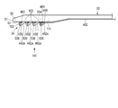
- FIG. 1 is a schematic view showing a treatment system according to the first to fourth embodiments, including each modification.
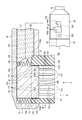
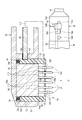
- FIG. 2 is a view showing a cross section of the energy treatment tool of the treatment system according to the first embodiment with the needle portion protected by the cover portion and an outline of the handle.
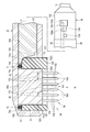
- FIG. 3 is a view schematically showing a cross section and a handle in a state in which a needle portion is exposed to a cover portion in the energy treatment apparatus according to the first embodiment.
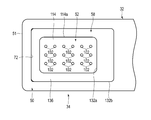
- FIG. 4 is a schematic view of the end effector of the energy treatment device as viewed from the direction indicated by arrow IV in FIGS. 2 and 3.
- FIG. 1 is a schematic view showing a treatment system according to the first to fourth embodiments, including each modification.
- FIG. 2 is a view showing a cross section of the energy treatment tool of the treatment system according to the first embodiment with the needle portion protected by the cover portion and an outline of the handle.
- FIG. 3 is a view schematically showing a cross section and a handle in a state in which
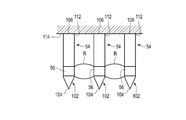
- FIG. 5 is a schematic view showing an energy output unit provided in a probe of a needle unit and showing a denatured area of a living tissue when energy is output from the energy output unit.
- FIG. 6A shows a state in which the insertion portion of the end effector and the endoscope of the energy treatment device according to the first embodiment is inserted through the external nostril, the nasal vestibule, and the lower nasal passage into the lower nasal turbinate to be treated in the nasal cavity
- FIG. 6B is a schematic cross-sectional view showing the tip and energy output portion of the needle shown in FIG. 3 disposed in the superficial layer of the lamina limba through the mucosal epithelial layer of the lower turbinate.
- FIG. 6A shows a state in which the insertion portion of the end effector and the endoscope of the energy treatment device according to the first embodiment is inserted through the external nostril, the nasal vestibule, and the lower nasal passage into the lower nasal turbinate to be treated in the nasal cavity
- FIG. 7 shows an energy output unit provided on the needle of the needle unit in the end effector according to the first modification of the first embodiment, and a diagram of a living tissue when energy is output from the energy output unit.
- 5 is a schematic view showing a modified region different from that shown in FIG.
- FIG. 8 shows an energy output unit provided on a needle of a needle unit in an end effector according to a second modification of the first embodiment, and a diagram of a living tissue when energy is output from the energy output unit.
- FIG. 10 is a schematic view showing a modified region different from that shown in FIG.
- FIG. 9 is a view schematically showing a cross section and a handle in a state where a needle portion is protected by a cover portion in the energy treatment apparatus according to the second embodiment.
- FIG. 10 is a view schematically showing a cross section and a handle in a state in which a needle portion is exposed to a cover portion in the energy treatment apparatus according to the second embodiment.
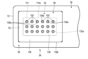
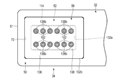
- FIG. 11 is a schematic view of the end effector of the energy treatment device, as viewed from the direction indicated by arrow XI in FIG. 9 and
- FIG. 12 shows a modification of the end effector of the energy treatment device shown in FIG.
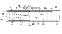
- FIG. 13 is a schematic view of the energy treatment tool according to the third embodiment, in which the cover portion protects the needle portion, as viewed from the direction indicated by the arrow XIII in FIG. FIG.
- FIG. 14 is a schematic view of the energy treatment tool according to the third embodiment, in which the cover portion protects the needle portion, as viewed from the direction indicated by the arrow XIV in FIG.
- FIG. 15 is a schematic view of the energy treatment tool according to the third embodiment, showing a state in which the needle portion is exposed to the cover portion, as viewed from the direction indicated by the arrow XV in FIG.
- FIG. 16 is a schematic view of the energy treatment tool according to the third embodiment, in which the needle portion is exposed to the cover as viewed from the direction indicated by arrow XVI in FIG. FIG.
- FIG. 17 is a schematic view of the energy treatment tool according to the modification of the third embodiment, in which the cover portion protects the needle portion, as viewed from the direction indicated by the arrow XVII in FIG.
- FIG. 18 is a schematic view of the energy treatment tool according to the modification of the third embodiment, in which the cover portion protects the needle portion, as viewed from the direction indicated by the arrow XVIII in FIG.
- FIG. 19 is a schematic view of the energy treatment tool according to the modification of the third embodiment, viewed from the direction indicated by the arrow XIX in FIG. 20, with the needle portion exposed to the cover portion.
- FIG. 20 is a schematic view of the energy treatment tool according to the modification of the third embodiment, viewed from the direction indicated by the arrow XX in FIG.
- FIG. 21 is a schematic view of the energy treatment tool according to the fourth embodiment, in which a state in which the needle portion is protected by the cover portion is viewed from the direction indicated by the arrow XXI in FIG.
- FIG. 22 is a schematic view of the energy treatment tool according to the fourth embodiment, in which the cover portion protects the needle portion, as viewed from the direction indicated by arrow XXII in FIG.
- FIG. 23 is a schematic view of the energy treatment tool according to the fourth embodiment, viewed from the direction indicated by arrow XXIII in FIG.
- FIG. 24 is a schematic view of the energy treatment tool according to the fourth embodiment, showing the state in which the needle portion is exposed to the cover portion, as viewed from the direction indicated by the arrow XXIV in FIG.
- the treatment system 10 shown in FIG. 1 is used to treat the nasal cavity, in particular the inferior turbinate.
- the treatment system 10 includes an energy treatment device 12 and an energy source 14.
- the treatment system 10 of the present embodiment includes an endoscope 16 and a controller 18 having a function as a power source, as well as an energy treatment tool 12 and an energy source 14.
- the controller 18 includes, for example, a processor, and the endoscope 16 is controlled by the processor. As the treatment system 10, the endoscope 16 and the controller 18 are not necessarily required.
- Power is supplied to the endoscope 16 from, for example, a controller 18 used as a power supply via a cable 17.
- the endoscope 16 captures an image of a position facing, for example, the distal end of the insertion unit 22 and displays the image on the display 20.
- the insertion portion 22 of the endoscope 16 may be formed to be rigid so as to maintain its shape, or may be formed to have a flexibility that allows it to be bent appropriately.
- the energy treatment device 12 has an insertion portion 32 in which the longitudinal axis L is defined, and an end effector (treatment portion) 34.
- the energy treatment device 12 has a handle 36 provided on the proximal side of the insertion portion 32.
- the proximal end of the insertion portion 32 is connected to a handle 36 held by the operator.
- the energy treatment device 12 preferably includes a rotation knob (pivot portion) 38 provided between the insertion portion 32 and the handle 36 and rotatable about the longitudinal axis L of the insertion portion 32.
- the rotation knob 38 may be provided in the insertion portion 32.
- the rotation knob 38 is integrated into the insert 32.
- An energy source 14 is connected to the handle 36 via a cable 13.
- a switch 15 is connected to the energy source 14.
- the switch 15 is connected to the energy source 14 and may be provided, for example, in the insertion portion 32, the handle 36 or the rotation knob 38.
- the energy output unit 56 is described as a high frequency electrode through which a high frequency current flows.
- treatment can be performed using various types of energy such as a heater that generates heat.
- the energy output unit 56 may dispose a heater on the high frequency electrode so that the energy treatment device 12 can simultaneously perform the treatment using the high frequency current and the treatment using the heat of the heater.
- the energy source 14 may be provided on the handle 36. In this case, energy is transmitted from the energy source 14 including a battery (not shown) provided on the handle 36 to the energy output unit (output unit) 56 through the insertion unit 32 and the later-described base 52 of the end effector 34.
- the energy source 14 including a battery (not shown) provided on the handle 36 to the energy output unit (output unit) 56 through the insertion unit 32 and the later-described base 52 of the end effector 34.
- the switch 15 may be configured to transmit a signal to the energy source 14 in conjunction with the position of a cover (cover) 58 described later, the position of the movable rod 82, and / or the position of the operation element 156. .
- the operation of the switch 15 also causes the energy source 14 toward the end effector 34 Energy may not be transmitted.
- the operation of the switch 15 causes the energy source 14 to transfer energy toward the end effector 34. It may be transmitted.
- the end effector 34 is provided at the tip of the insertion portion 32.
- the insertion portion 32 and the end effector 34 are integrated. Therefore, the insertion portion 32 and the end effector 34 can be integrally rotated with respect to the handle 36 in accordance with the operation of the rotation knob 38 about the longitudinal axis L.
- a lock may be provided between the handle 36 and the rotation knob 38 or between the handle 36 and the insertion portion 32 to prevent the insertion portion 32 from rotating unintentionally with respect to the handle 36. .
- the lock may exert a frictional force between the handle 36 and the rotation knob 38 or between the handle 36 and the insertion portion 32, which prevents the motion between them, for example, by fitting them together.
- a mechanism may be provided. For example, in conjunction with the pressing of the switch 15 and / or the movement of the operating element 156 which maintains the cover portion 58 in the second position described later, between the handle 36 and the rotation knob 38 or the handle 36 A mechanism may be provided to prevent rotation between the and the insertion portion 32.
- the insertion portion 32 is formed, for example, in a pipe shape.
- the insertion portion 32 may be formed of an appropriate material.
- the insertion portion 32 is made of, for example, a metal material whose outer peripheral surface is covered with a material having electrical insulation.
- a position of the insertion portion 32 between the proximal end of the end effector 34 and the handle 36 may be a so-called malleable material which can be bent into an appropriate shape by application of pressure.
- the insert 32 can be bent prior to treatment, for example to the shape of the nose of each patient, and maintain that shape during treatment.
- the end effector 34 on the distal end side of the insertion portion 32 can be maintained in the direction during the treatment in a state in which the end effector 34 is appropriately oriented with respect to the insertion portion 32. Since the end effector 34 and the insertion portion 32 are inserted into the narrow cavity of the patient, an appropriate external force may be applied from the wall in the nasal cavity. Even in this case, the insertion portion 32 formed of a mariable material has an appropriate resistance to an external force from, for example, a wall surface or the like in a body cavity. For this reason, although the insertion part 32 accept
- the insertion portion 32 have a curved portion having the same structure as that of the insertion portion of a known endoscope which can be inserted into, for example, the stomach or the large intestine.
- the end effector 34 may be accessed in the vicinity of the object to be treated while appropriately actively bending the bending portion according to the shape in the nasal cavity. Then, by appropriately bending the bending portion, the end effector 34 on the distal end side of the insertion portion 32 is oriented in an appropriate direction with respect to the insertion portion 32, and the state is maintained.
- the handle 36 may be provided with a lock that prevents the bending portion of the insertion portion 32 from being unintentionally bent during treatment.
- the lock may be interlocked with, for example, the pressing of the switch 15 and / or the movement of the operation element 156 that maintains the state in which the cover 58 is in the second position described later.
- the lock may be linked to a mechanism for preventing rotation between the handle 36 and the knob 38 or between the handle 36 and the insertion portion 32 described above.
- the base 52, the needle portion 54, the output portion 56, and the cover portion 58 of the end effector 34 are preferably directed in a direction (crossing direction) away from the longitudinal axis L of the insertion portion 32 in this embodiment.
- the end effector 34 is assumed to be oriented in a direction orthogonal to the longitudinal axis L for simplification of the description.
- the direction in which the end effector 34 is directed with respect to the insertion portion 32 is not limited to the direction orthogonal to the longitudinal axis L, and can be set as appropriate.
- a housing 50 of the end effector 34 is provided on the distal end side of the insertion portion 32.
- the housing 50 is preferably integrated with the distal end of the insertion portion 32.
- the outer peripheral surface of the housing 50 is also covered with a material having electrical insulation, similarly to the insertion portion 32.
- the distal end 51 of the housing 50 is preferably formed in a blunt shape.
- the end effector 34 has a plate-shaped or block-shaped base (energy delivery device) 52, a needle portion 54, and an energy output portion 56 provided on the needle portion 54.
- the end effector 34 has a cover 58 that protects the needle 54 in the path from the entrance to the treatment target toward the treatment target.
- the cover portion 58 is provided outside the base 52 and is movable with respect to the base 52.
- the cover portion 58 has a first position for protecting the living tissue from the tip 104 and the energy output portion 56 of the needle portion 54 described later by movement in a predetermined direction, the tip 104 of the needle portion 54 and the energy output portion 56. It is movable (movable) between a second position where the living tissue can be treated.
- the cover portion 58 is preferably movable in the direction intersecting the longitudinal axis L, in particular, in the orthogonal direction.
- the cover 58 is preferably formed of a resin material having electrical insulation. In the present embodiment, an example in which the cover portion 58 is provided outside the needle portion 54 will be described.
- the housing 50 has a concave inner circumferential surface (concave surface) 50a.
- the base 52 is provided on the distal end side along the longitudinal axis L of the insertion portion 32 and is fixed to the housing 50. Specifically, the base 52 is fixed to the inner circumferential surface 50 a of the housing 50.
- the needle portion 54 is supported by the base 52 on the side opposite to the portion fixed to the inner circumferential surface 50 a of the housing 50.
- the needle portion 54 refers to a bundle of a plurality of needle-like probes (microneedles) 102 described later and a region in which the plurality of probes 102 are formed.
- the insertion portion 32 is provided with at least one pair of electrical paths (transmission paths).
- the base 52 is electrically connected to the energy source 14 via a lead wire (not shown) and / or a component of the insertion portion 32 or the like.
- the insertion unit 32 may be electrically connected to the energy output unit 56 and may be used as part of a transmission line that transmits the energy supplied from the energy source 14 to the energy output unit 56.
- the moving rod 82 provided inside the inner circumferential surface 32 a of the insertion portion 32 is electrically connected to the energy output unit 56, and transmits the energy supplied from the energy source 14 to the energy output unit 56. It can be used as part of a track.
- the base 52 is used as a delivery device for transferring energy to the energy output unit 56 provided in the needle 54.
- Needle portion 54 includes a plurality of probes 102.
- the plurality of probes 102 are provided on the distal end side along the longitudinal axis L of the insertion portion 32.
- Each probe 102 protrudes with respect to the base 52 and can puncture a living tissue.
- Each probe 102 has a tip (needle tip) 104 at its distal end. For this reason, the needle portion 54 has a pointed end 104 projecting with respect to the base 52, and is pierced from the pointed end 104 into the living tissue.
- Each probe 102 has a base 106 supported by a base 52. In the present embodiment, it is preferable to have electrical insulation between the base 106 and the tip 104 of each probe 102 except for the energy output portion 56.
- Each probe 102 is preferably straight and parallel to one another.
- the extension direction of each probe 102 corresponds to the direction in which the end effector 34 is directed.
- the extension direction of each probe 102 is orthogonal or substantially orthogonal to the longitudinal axis L, as an example.
- the extension direction of each probe 102 is not limited to the direction orthogonal to or substantially orthogonal to the longitudinal axis L, and can be set as appropriate.
- Each probe 102 is preferably formed straight from the base 106 to the pointed end 104 as described above, but may be bent as appropriate.
- the base 52 has a support 112 for supporting the base 106 of each probe 102 of the needle 54. As shown in FIG. 4, in the support portion 112, as an example, the probes 102 are arranged in a lattice shape at appropriate intervals. The density of the probes 102 in the needle portion 54 is appropriately set according to the size of the treatment area (the area indicated by the symbol R in FIG. 5) in the energy output unit 56 of each probe 102.
- the base 52 has a defining surface 114 that defines the length (protruding length) from the base 52 to the tip 104 of each probe 102 of the needle 54.
- the defining surface 114 is a flat surface, and the extension direction of each probe 102 is orthogonal to the defining surface 114. It is preferable that the length (protruding length) of each probe (microneedle) 102 with respect to the defining surface 114 of the base 52 is the same or substantially the same.
- the length and diameter of each probe 102 are set depending on the material, the treatment target, and the position of the second end surface (end) 136 of the cover 58.
- the outer diameter of each probe 102 is preferably approximately 200 ⁇ m.
- the length of each probe 102 depends on the positional relationship with the cover portion 58.
- the puncture depth from the surface of the mucous epithelial layer MEL to be described later to the energy output portion 56 is about 0.05 mm to 0.8 mm Is preferred.
- the housing 50 has a guide 72 that guides the movement of the cover 58 relative to the base 52 and the needle 54.
- the guide 72 is provided on the outside of the base 52.
- the cover portion 58 is provided on the outside of the base 52.
- the cover portion 58 is movable in parallel or substantially in parallel with the extension direction of the probe 102 extended straight from the base 52.
- the extension direction of the probe 102 is a direction intersecting the longitudinal axis L of the insertion portion 32.
- the cover portion 58 is movable along the direction intersecting the longitudinal axis L of the insertion portion 32. That is, the second end surface (end portion) 136 of the cover portion 58 is movable along the direction in which the needle portion 54 protrudes. Therefore, in the housing 50, the cover 52 provided on the outer periphery of the base 52 and the needle 54 is supported movably with respect to the housing 50, the base 52 and the needle 54.
- the end effector 34 has a biasing body 74 capable of moving the cover 58 along the guide 72 relative to the base 52 and the needle 54.
- the biasing body 74 is provided between the cover portion 58 and the inner circumferential surface 50 a of the housing 50.
- a plurality of coil springs 74 a are used as the biasing body 74 as an example.
- One end of each coil spring 74 a is supported by the inner circumferential surface 50 a of the housing 50.
- the other end of each coil spring 74 a is supported by a first end face (edge) 134 of the cover 58 described later.
- the coil spring 74 a of the present embodiment urges the first end surface 134 of the cover 58 toward the inner circumferential surface 50 a of the housing 50.
- a rubber material may be used instead of the plurality of coil springs 74a.
- the energy treatment device 12 has a lock mechanism 84 provided on the handle 36 and holding the position of the cover 58 relative to the base 52.
- the lock mechanism 84 is disposed, for example, at one of the end portions 154 a and 154 b of the slot 154 described later, whereby the operation element 156 is held.
- the energy treatment device 12 of the present embodiment is locked in the second position shown in FIG. 3 while the cover portion 58 is locked in the first position shown in FIG.
- the lock mechanism 84 is provided on the handle 36 and holds the position of the cover 58 with respect to the base 52 and the needle 54.
- the lock mechanism 84 may be formed in the insertion portion 32 in which the moving rod 82 is included. For this reason, the lock mechanism 84 may be provided on at least one of the handle 36 and the moving rod 82.
- the cover portion 58 is disposed outside the outer edge 114 a of the defining surface 114.
- the cover 58 has a cover body 132.
- the cover main body 132 is described as being cylindrical (the cross section is annular) in the present embodiment, the cover main body 132 is not necessarily cylindrical, and the cross section may be substantially C-shaped or U-shaped as appropriate. The shape of is acceptable.
- the cover body 132 has an inner circumferential surface 132a and an outer circumferential surface 132b.
- the cover main body 132 has a first end face 134 opposite to the inner peripheral surface 50 a on the back side of the housing 50 and a second end face (reference surface or reference edge) 136 opposite to the first end face 134. Have.
- the first end face 134 and the second end face 136 may be flat or curved. Further, the second end face 136 of the cover portion 58 is described as a face here, but may be not a face as long as it is formed as an end portion, for example, curved in a protruding direction.
- the second end face (end portion) 136 is movable (movable) in a predetermined direction (specifically, the protruding direction of the needle portion 54) with respect to the base 52, and with the pointed end 104 of the probe 102 of the needle portion 54.
- the second end face 136 of the cover portion 58 is formed in the direction in which the needle portion 54 protrudes with respect to the defined surface 114 of the base 52, and the second end face 136 is formed of the inner peripheral surface (wall surface) 132 a and the outer peripheral surface (wall surface) 132 b of the cover main body 132. It is formed continuously at the distal end.
- the second end surface 136 of the cover portion 58 is disposed at the same position as the pointed end 104 of the needle portion 54 or at a position (projecting direction side) protruding from the pointed end 104. Let this be the first position. Thus, when the cover portion 58 is in the first position, the second end surface 136 of the cover portion 58 is at the same defined surface 114 of the base 52 as the pointed end 104 of the probe 102 of the needle portion 54. It is placed far away.
- the second end surface (end portion) 136 of the cover portion 58 is disposed at the same position as the pointed end 104 of the needle portion 54 or protruding from the pointed end 104 Protect the tip 104 of the needle 54 and the output 56. That is, when the cover portion 58 is in the first position, it covers and covers the outside of the needle portion 54 in a state where the pointed end (needle tip) 104 of the probe 102 is not exposed.
- the second end face 136 of the cover portion 58 is disposed at a position closer to the base 52 (the base 52 side) than the pointed end 104 of the needle portion 54 and the energy output portion 56. This is the second position. For this reason, the second end surface 136 of the cover portion 58 is disposed at a position closer to the defining surface 114 of the base 52 than the pointed end 104 of the probe 102 of the needle portion 54 and the energy output portion 56. As described above, when the cover portion 58 is in the second position, the second end surface (end portion) 136 of the cover portion 58 is retracted with respect to the pointed end 104 of the needle portion 54 and the output portion 56.
- the pointed end (needle tip) 104 and the energy output portion 56 of the probe 102 project from the second end surface (end portion) 136 with respect to the cover portion 58. At this time, the pointed end (needle tip) 104 of the probe 102 and the energy output unit 56 are exposed to the cover 58.
- the end effector 34 can puncture the pointed end 104 of the needle portion 54 and the energy output portion 56 into the living tissue.
- the cover portion 58 is movable (movable) between the first position (see FIG. 2) and the second position (see FIG. 3). Therefore, when the cover portion 58 moves from the first position to the second position, the pointed end (needle tip) 104 of the probe 102 and the energy output portion 56 are attached to the second end surface (end portion) 136 of the cover portion 58. It can be projected against.
- the second end face 136 of the cover portion 58 in the second position where the pointed end 104 of each probe 102 is exposed, is closer to the pointed end 104 of the needle portion 54 than the defined surface 114 of the base 52. is there.
- the second end face 136 of the cover portion 58 in the second position where the pointed end 104 of each probe 102 is exposed, is at a position farther to the pointed end 104 of the needle portion 54 than the defined surface 114 of the base 52. It is good.
- the energy output 56 is provided at a predetermined position between the tip 104 and the base 106 of each probe 102.
- the position of the energy output unit 56 is adjusted such that the energy output unit 56 reaches the mucosal proper layer through the mucosal epithelial layer.
- the energy output unit 56 can output energy to the outside of the needle unit 54 by supplying energy from the energy source 14 through the cable 13.
- the energy output unit 56 is provided between the first electrode 122 having conductivity, the second electrode 124 having conductivity, and the first electrode 122 and the second electrode 124 in the present embodiment. And an insulating spacer 126.
- the first electrode 122 and the second electrode 124 are electrically connected to the energy source 14 through independent electrical paths (leads).
- each energy output unit 56 can locally modify, for example, the tissue in the region R shown in FIG. 5 in the living tissue.
- the energy source 14 can monitor the state of the mucosal tissue by obtaining information such as the impedance of the mucosal tissue in the vicinity of each energy output unit 56 using each energy output unit 56 as a sensor. For this reason, by using the present system 10, it is possible to grasp the coagulation state of the mucosal tissue as in the known technique. Further, the energy source 14 can grasp whether or not it is in contact with a living tissue by monitoring information such as impedance. For this reason, the energy source 14 does not have enough energy to affect the living tissue in contact with the energy output unit 56 immediately before emitting energy that affects the living tissue in contact with the energy output unit 56. It is preferable to take out. Therefore, after the energy source 14 determines whether the energy output unit 56 of each probe 102 is in contact with the living tissue reliably, the energy affecting the living tissue contacting the energy output unit 56 is determined. Can be
- the energy source 14 may be able to adjust the current flowing to each energy output 56 based on the individual biometric information of each energy output 56.
- the second end surface 136 of the cover portion 58 with respect to the defining surface 114 of the base 52 It is located close to the point 104.
- the end effector 34 can puncture the pointed end 104 of the needle portion 54 and the energy output portion 56 into the living tissue.
- the position of the energy output unit 56 with respect to the second end face 136 of the cover 58 when the cover 58 is in the second position is the distance to reach the mucosal proper layer through the mucosal epithelial layer.
- the defined surface 114 of the base 52 is closer to the pointed end 104 of each probe 102 than the second end surface 136 of the cover portion 58. It may be close.
- the projection length of the energy output unit 56 with respect to the defining surface 114 of the base 52 when the cover unit 58 is in the second position is the distance to reach the mucosal proper layer through the mucosal epithelial layer.
- the first end surface 134 of the cover portion 58 has an inclined surface 134 a.
- the inclined surface 134 a is formed at a position on the proximal side along the longitudinal axis L in the first end surface 134 of the cover portion 58.
- the inclined surface 134a is formed as a flat surface or a curved surface.
- the energy treatment device 12 is provided between the handle 36 and the end effector 34 and has a movable rod (moving body) 82 movable along the longitudinal axis L.
- the moving rod 82 is formed, for example, of the same mariable material as the insertion portion 32 and is bent following the insertion portion 32.
- the tip end portion of the moving rod 82 is in contact with the inclined surface 134 a of the cover portion 58 continuous with the projection 142 in contact with or close to the base 52, the inclined surface 144 continuous with the projection 142, and the inclined surface 144. And a contact surface 146. It is preferable that the moving rod 82 and the protrusion 142 be electrically insulated, for example, a coating having an electrical insulating property is provided on the outer surface.
- the inclined surface 144 is formed as a flat surface or a curved surface.
- the inclined surface 144 is inclined with respect to a plane orthogonal to the longitudinal axis L.
- the protrusion 142 is at a position close to the inner circumferential surface 50 a of the housing 50 with respect to the inclined surface 144.
- the proximal end of the moving rod 82 extends to the handle 36.
- the handle 36 has, for example, a cylindrically formed main body 152, a slot (groove) 154 formed in the main body 152, and an operation element 156 connected to the proximal end of the movable rod 82 through the slot 154.
- the slot 154 is formed along the longitudinal axis L.
- the slot 154 has a continuous first end 154 a and a second end 154 b as part of the locking mechanism 84.
- the first end 154 a is formed on the distal end of the slot 154 along the longitudinal axis L.
- the second end 154 b is formed in the slot 154 at a proximal position along the longitudinal axis L.
- the slot 154 including the first end portion 154a and the second end portion 154b is generally formed in a substantially U shape, as an example.
- the manipulator 156 is disposed at the first end 154a of the slot 154 when the cover portion 58 maintains or is locked in the first position shown in FIG.
- the manipulator 156 is disposed at the second end 154b of the slot 154 when the cover portion 58 maintains or is locked in the second position shown in FIG.
- the operating element 156 of the handle 36 is at one end 154 a of the slot 154 and is biased in the width direction W orthogonal to the longitudinal axis L Is preferred.
- the contact surface 146 of the tip of the moving rod 82 is in contact with the inclined surface 134 a of the first end surface 134 of the cover 58. For this reason, the first end surface 134 of the cover portion 58 is located at a distance from the inner circumferential surface 50 a of the housing 50.
- the operating element 156 of the handle 36 is at the other end 154 b of the slot 154 and biased toward the width direction W orthogonal to the longitudinal axis L Is preferred.
- the inclined surface 144 of the tip end portion of the moving rod 82 is in contact with the inclined surface 134 a of the first end surface 134 of the cover portion 58. For this reason, the first end surface 134 of the cover portion 58 is at a position close to the inner circumferential surface 50 a of the housing 50.
- the handle 36 is provided with an indicator 158.
- the indicator 158 illuminates only while energy from the energy source 14 is being output.
- the indicator 158 preferably illuminates only while energy is provided to each energy output 56 and the tissue is being treated at each energy output 56.
- the operation of the treatment system 10 according to the present embodiment will be described.
- the energy treatment tool 12 is used to treat the mucous membrane of the nose.
- the energy treatment tool 12 can be used to perform treatment in other cases as well.
- allergic rhinitis is a disease with a large number of affected people worldwide. This disease includes seasonal allergic rhinitis called so-called hay fever, and perennial allergic rhinitis using house dust and pets as allergens. The main symptoms of these allergic rhinitis are stuffy nose, runny nose, sneezing and itching. Basically, medication is the first choice for any condition, but surgery can be indicated for critically ill patients.
- the case of performing an operation aiming at (1) contraction and modulation of the nasal mucosa using the energy treatment tool 12 is mainly described.
- the mucosa of the inferior turbinate is being recognized as the main site of nasal allergic reactions.
- appropriate modulation treatments such as cauterizing or coagulating the mucous membrane of the inferior turbinate are effective.
- the operator places the cover portion 58 of the end effector 34 of the energy treatment tool 12 in the first position (see FIG. 2). As shown in FIG. 6A, the operator applies the end effector 34 of the energy treatment tool 12 to the patient's nostril EN, the nasal vestibule VN, and the lower nasal turbinate IT to be treated in the nasal cavity CN, for example, through the inferior nasal passage IM. Directly insert.
- the operator places the tip of the insertion portion 22 of the endoscope 16 at a position where a part of the inner wall of the nasal cavity CN and a part of the end effector 34 of the energy treatment tool 12 can be observed.
- the endoscope 20 displays a part of the inner wall of the nasal cavity CN and a part of the end effector 34 of the energy treatment tool 12 on the display 20.
- the posterior nasal nerve N1 behind the inferior turbinate IT may be accessed through the middle nasal passage MM instead of the inferior nasal passage IM.
- each probe 102 is closer to the defined surface 114 of the base 52 than the second end surface 136 of the cover 58. is there. Therefore, when the end effector 34 of the energy treatment tool 12 is inserted from the nasal cavity CN toward the lower turbinate IT to be treated, the tip 104 of each probe 102 is from the nasal cavity CN of the patient to the lower turbinate IT to be treated. It is prevented from hitting the wall in between. Also, since the tip 104 of each probe 102 is prevented from hitting the wall surface from the nasal cavity CN of the patient to the lower nasal turbinate IT to be treated, each probe 102 is loaded before the treatment to be treated. Is being prevented.
- the mucous epithelial layer MEL and the lamina intestinal lamina LPM are present from the outside to the inside.
- the pointed end 104 of each probe 102 of the needle portion 54 is not in contact with the surface of the mucous membrane epithelial layer MEL Is preferred, but may be in contact.
- the operator moves the operating element 156 of the handle 36 to the position shown in FIG. 3 against the biasing force applied to the operating element 156 from the position shown in FIG. At this time, the moving rod 82 is moved to the proximal side along the longitudinal axis L of the insertion portion 32 in conjunction with the movement of the operation element 156.
- the first end surface 134 of the cover portion 58 maintains the state where the inclined surface 134a abuts on the inclined surface 144 of the tip of the movable rod 82 along the guide 72. While being close to the inner circumferential surface 50 a of the housing 50.
- the positions of the cover portion 58 and the moving rod 82 with respect to the housing 50 are defined.
- the cover portion 58 of the end effector 34 is held at the second position.
- the protruding length of the tip 102 of the probe 102 with respect to the second end surface 136 of the cover portion 58 is defined.
- the protrusion length to the energy output part 56 with respect to the 2nd end surface 136 of the cover part 58 is prescribed
- the operator maintains the second end surface 136 of the cover portion 58 of the end effector 34 in contact with the mucous membrane of the inferior turbinate IT. Therefore, as shown in FIG. 6B, in a state where the second end face 136 of the cover portion 58 is in contact with the surface of the mucous membrane epithelial layer MEL, the pointed end 104 of the probe 102 passes through the mucous membrane epithelial layer MEL. Reach LPM.
- the point 104 of the probe 102 does not reach the bone B.
- the energy output unit 56 is disposed in the upper layer of the mucosal lamina limba LPM including the shallow layer of the mucosal lamina limba LPM.
- the outer peripheral surfaces of the first electrode 122, the second electrode 124 and the spacer 126 of the energy output unit 56 shown in FIG. 5 are in contact with the upper layer including the shallow layer of the mucosal proper layer LPM.
- the indicator 158 provided on the handle 36 is turned on, and the first electrode 122 and the second electrode 122 of the energy output portion 56 provided on each of the probes 102 from the energy source 14 are turned on.
- the high frequency current is supplied to the shallow layer of the lamina basement LPM through between the electrodes 124 of the
- the shallow layer of the mucosal lamina basement LPM which is the tissue in contact with the energy output unit 56, and the surrounding tissue (region indicated by symbol R in FIG. 5) are denatured, for example, locally cauterized by a high frequency current .
- the treatment region R of each probe 102 in the needle 54 is changed depending on the state of tissue, the magnitude of the current, and the like.
- the energy output unit 56 is used, for example, as a sensor for obtaining biological information such as impedance. Then, the energy source 14 electrically connected to the energy output unit 56 grasps the state (biological information) of the shallow layer of the mucosal proper layer LPM in contact with the energy output unit 56 and the tissue in the vicinity thereof. There is. For this reason, the degeneration state of the tissue in contact with the energy output unit 56 and the surrounding tissue is estimated while the high frequency current is flowing.
- the energy source 14 automatically stops the output of energy to the tissue in contact with the energy output unit 56 and the surrounding tissue when it is determined that the biological information has reached the predetermined threshold. At this time, the energy source 14 turns off the indicator 158 even when the switch 15 is pressed.
- the operator can recognize the end of the treatment, that is, the end of the output of energy to the tissue in contact with the energy output unit 56 and the tissue in the vicinity thereof by turning off the indicator 158.
- the indicator 158 When the indicator 158 is turned off, the energy source 14 may completely stop the supply of energy or may flow a weak current which does not affect the living tissue. That is, when the indicator 158 is turned off, the output from the energy source 14 is automatically reduced.
- the energy output unit 56 that has reached the mucosal lamina limbal MEL cauterizes the shallow layer of the mucosal lamina limbal LPM by flowing a high frequency current.
- the site to be cauterized by the energy output unit 56 is limited to a narrow range, and cautery treatment involving damage to the surface of the mucous membrane epithelial layer MEL is prevented.
- the superficial layer of the mucosal lamina limbal lamina limbal layer LPM is denatured (coagulated) to form a scar in the superficial layer of the mucosal lamina intestinal LPM without damaging the surface of the mucosal epithelial layer MEL.
- a mucous membrane which is not easily swollen is formed in the shallow layer of the lamina limbal lamina intestinal IT.
- the energy treatment device 12 By using the energy treatment device 12 according to the present embodiment, it is possible to prevent the surface of the mucosal epithelial layer MEL from being damaged. For this reason, it can prevent affecting the cilia motor function of the surface of mucous membrane epithelial layer MEL.
- the lower turbinate IT Since the lower turbinate IT has an appropriate size, it is preferable to perform the treatment in multiple times with the energy treatment tool 12.
- the tip 104 of the probe 102 is removed from the lamina limbal MEL of the inferior turbinate IT, and the second end face 136 of the cover 58 is in contact with the mucoepithelial layer MEL in the adjacent part of the inferior nasal turbinate IT. Get in touch.
- the tip 104 of the probe 102 is allowed to reach the lamina limba LPM through the mucous membrane epithelial layer MEL.
- the operator denatures the tissue in contact with the energy output unit 56 and the surrounding tissue into appropriate states by the supply of energy from the energy source 14 as described above.
- the operator moves the operating element 156 from the other end 154 b of the slot 154 toward the one end 154 a.
- the movable rod 82 is advanced along the longitudinal axis L of the insertion portion 32.
- the inclined surface 144 of the moving rod 82 presses the inclined surface 134 a of the first end surface 134 of the cover portion 58 against the biasing force of the spring 74 a of the biasing body 74.
- the contact surface 146 is brought into contact with the inclined surface 134a.
- the second end surface 136 of the cover portion 58 is farther from the defining surface 114 of the base 52 than the pointed end 104 of the probe 102.
- the pointed end 104 of the probe 102 is closer to the defining surface 114 of the base 52 than the second end surface 136 of the cover portion 58. Then, the operating element 156 is maintained at the other end 154 b of the slot 154. Therefore, the cover portion 58 returns from the second position shown in FIG. 3 to the first position shown in FIG.
- the inferior turbinate IT is generally curved. Therefore, the operator may want to adjust the orientation of the end effector 34. In this case, it may be preferable to maintain the gripping state of the handle 36 because the operator needs to operate the operating element 156, for example. For this reason, the operator rotates the rotation knob 38 about the longitudinal axis L with respect to the handle 36. As the rotation knob 38 rotates, the insertion portion (cylindrical body) 32 connected to the rotation knob 38 and the inner moving rod 82 rotate together. Therefore, the orientation of the end effector 34 on the distal end side of the insertion portion 32 is adjusted to an appropriate state.
- the operator 156 of the handle 36 is moved to an appropriate position, and the shallow layer of the mucosal proper layer LPM of the inferior turbinate IT is appropriately cauterized as described above.
- the nerve N to be treated is often present near the surface of the bone B.
- the height of the cover 58 and / or the probe may be used to perform the operation aiming at the contraction and modulation of the nasal mucosa and the operation aiming at the interruption of the nerve transmission.
- the length of 102 may be different from the example shown in FIG. 6B described above. For this reason, the treatment tool 12 when performing the treatment of (3) is different from the treatment tool 12 when performing the treatment of (1).
- the cover portion 58 when the cover portion 58 is in the second position, the position of the energy output portion 56 with respect to the second end surface (reference surface) 136 of the cover portion 58 or the defining surface 114 of the base 52 is determined. For this reason, the depth from the surface of the mucous membrane epithelial layer MEL to the energy output unit 56 can be made constant. Therefore, the high frequency current can be used in the energy output unit 56 to reliably cauterize the nerve N in the mucosal proper layer LPM close to the surface of the bone B. For this reason, the allergic reaction in the lower turbinate IT can be suppressed using the energy treatment device 12 according to the present embodiment, and the occurrence of nasal leakage can be suppressed.
- the cover portion 58 can protect the path to the subject. For this reason, according to the present embodiment, it is possible to provide the energy treatment device 12 capable of protecting the cavity when accessing the treatment target. Further, when the end effector 34 is accessed to the treatment target, the cover portion 58 can protect each probe 102 of the needle portion 54.
- the needle portion 54 is fixed to the base 52 and does not move.
- the electrical path of the energy treatment device 12 may be subjected to a mechanical load that is received when the needle 54 is inserted into and removed from the living tissue.
- the load on the electrical path due to the movement of the needle relative to the insertion part need not be considered. Therefore, according to the present embodiment, it is possible to provide the energy treatment device 12 capable of reducing the load applied to the electrical path.
- the end effector of the treatment tool 12 can be used without damaging other tissues, especially in the complex and narrow nasal cavity, and in the nasal cavity CN such as the wide and protruding inferior nasal turbinate IT. You can access 34.
- the non-invasive or minimally invasive end effector 34 of the treatment tool 12 is applied to the superficial layer of the mucosal lamina intestinal LPM that is effective in the current treatment without damaging the surface of the mucous membrane (mucosal epithelial layer MEL). Can be approached.
- the energy treatment tool 12 can be used to output energy only to the shallow layer of the mucosal lamina basement LPM to denature the tissue of the shallow layer of the mucosal lamina intestinal LPM.
- high-frequency current can be used to cauterize the tissue in the shallow layer of the mucosal lamina limbal.
- the cover portion 58 when the cover portion 58 is in the second position, the position of the energy output portion 56 with respect to the second end surface (reference surface) 136 of the cover portion 58 or the defining surface 114 of the base 52 is determined. For this reason, the depth from the surface of the mucous membrane epithelial layer MEL to the energy output unit 56 can be made constant. Therefore, the tissue of the shallow layer of the mucosal proper layer LPM can be reliably cauterized using the high frequency current in the energy output unit 56. Therefore, using the energy treatment device 12 according to the present embodiment, it is possible to suppress the allergic reaction in the lower turbinate IT, and improve or suppress the nasal congestion, that is, the nasal congestion.
- the symptom may be aggravated by the influence of the surface damage of the mucosal epithelial layer MEL for about half a day to about one week after the operation because of the surface damage of the mucosal epithelial layer MEL, for example. There is.
- the energy treatment tool 12 penetrates the probe (microneedle) 102 in the mucous membrane epithelial layer MEL, but it is difficult to give energy to the mucous epithelial layer MEL itself, and it is difficult to damage the surface of the mucous epithelial layer MEL, Only the shallow layer of the mucosal lamina limba LPM can be denatured (coagulated) by the application of energy. As described above, by using the energy treatment device 12 according to the present embodiment, since the surface of the mucosal epithelial layer MEL is not damaged, the therapeutic effect can be easily obtained immediately after the operation as compared with the conventional therapeutic means. .
- the example shown in FIG. 8 is a further modification of the example of the energy output unit 56 shown in FIG.
- the energy output portion 56 of the example shown in FIGS. 5 and 7 is located at the tip 104 of the probe 102 at a position closer to the base 106 than the tip 104.
- the energy output unit 56 of the example shown in FIG. 8 the energy output unit 56 exists at a position including the pointed end 104 of the probe 102. Even if the energy output part 56 is formed in this way, the area R shown in FIG. 8, for example, is denatured by the energy output between the energy output parts 56 of the adjacent probes 102. Therefore, a part of the shallow layer of the mucosal lamina limba LPM is appropriately cauterized.
- the position and the range of the region R can be adjusted by the arrangement of the energy output unit 56 provided in each of the probes 102 and the like.
- the treatment system 10 has a return electrode (not shown) connected to the energy source 14 and attached to the patient.
- the return electrode is attached to, for example, a patient's thigh.
- the energy output part 56 of each probe 102 of the end effector 34 is electrically connected and set to the same potential.
- a high frequency current is applied to the shallow layer of the mucosal proper layer LPM in contact with the energy output portion 56 provided in each of the probes 102 and the surrounding tissue, and the return electrode plate It will be collected.
- a portion to which a high-frequency high-frequency current flows is cauterized.
- a high-frequency current is applied to an appropriate depth of living tissue (for example, the shallow layer of mucosal lamina limbal MPM and the surrounding tissue), and the appropriate depth (the shallow layer of mucosal lamina limbal LPM and the surrounding tissue)
- an appropriate depth of living tissue for example, the shallow layer of mucosal lamina limbal MPM and the surrounding tissue
- the appropriate depth the shallow layer of mucosal lamina limbalPM and the surrounding tissue
- FIG. 9 is a modification of the first embodiment including each modification, and the same members as the members described in the first embodiment or members having the same functions are denoted by the same reference numerals, and the detailed description will be made. Omit.
- a plate-like member 138 is formed on the second end face 136 of the cover portion 58. Therefore, the plate member 138 moves following the movement of the cover 58 along the guide 72.
- the plate-like member 138 is formed with an opening 138 a through which the probes 102 of the needle portion 54 pass.
- a plurality of coil springs 74 b are used as the biasing body 74 as an example.
- One end of each coil spring 74b is supported by the inner circumferential surface 50a of the housing 50, as described in the first embodiment.
- the other end of each coil spring 74 b is supported by the first end surface 134 of the cover 58.
- the coil spring 74b biases the first end surface 134 of the cover 58 away from the inner circumferential surface 50a of the housing 50, unlike the case described in the first embodiment.
- a rubber material may be used instead of the plurality of coil springs 74b.
- the second end surface 136 of the cover 58 and the plate-like member 138 are disposed the same as the pointed end 104 of the needle 54 or on the side of the pointed end of the needle 104 in the projecting direction. Let this be the first position. For this reason, when the cover portion 58 is in the first position, the second end surface 136 of the cover portion 58 and the plate-like member 138 are the same as or larger than the pointed end 104 of the probe 102 of the needle portion 54.
- the cover portion 58 arranges the pointed end 104 of each probe 102 of the needle portion 54 closer to the base 52 than the second end face 136 and the plate member 138 Do.
- the cover portion 58 can be pushed in the direction of the inner circumferential surface 50 a of the housing 50. That is, as shown in FIG. 10, the cover portion 58 has the pointed end 104 and the energy output portion 56 of each probe 102 of the needle portion 54 through the opening 138a of the plate member 138 from the second end surface 136 and the plate member 138. It is also possible to arrange at a position far from the base 52.
- the second end surface 136 of the cover portion 58 and the plate member 138 are disposed closer to the base 52 than the pointed end 104 of the needle portion 54 and the energy output portion 56. This is the second position. Therefore, when the cover portion 58 is in the second position, the pointed end (needle tip) 104 and the energy output portion 56 of the probe 102 with respect to the cover portion 58 have the second end surface (end portion) 136 and the plate member 138. Protruding from Therefore, when the cover portion 58 is in the second position, the end effector 34 can puncture the tip 104 and the energy output portion 56 of each probe 102 of the needle portion 54 into the living tissue.
- the cover portion 58 is movable (movable) between the first position and the second position.
- the cover portion 58 is in the first position, the path from the entrance to the treatment target toward the treatment target is protected from the tip 104 of each probe 102, and each probe 102 used for treatment is protected.
- the central axis C of the moving rod 82 coincides or substantially coincides with the longitudinal axis L of the insertion portion 32.
- the slot 154 is not simply U-shaped, but has a proximally-extending extension 154c.
- the operation element 156 is disposed when moving the cover portion 58 from the first position to the second position and when moving the cover portion 58 from the second position to the first position.
- the tip of the movable rod 82 is used as a stopper. For this reason, even if the second end surface 136 of the cover portion 58 is pushed toward the inner circumferential surface 50 a of the housing 50, the movement of the cover portion 58 with respect to the housing 50 is restricted.
- the end effector 34 accesses the inferior turbinate IT. Then, the operator brings the second end surface 136 of the cover portion 58 of the end effector 34 and the plate member 138 into contact with the surface of the mucosal epithelial layer MEL of the inferior turbinate IT.
- the pointed end 104 of each probe 102 is a defined surface of the base 52 rather than the second end surface 136 of the cover portion 58 and the plate member 138. It is located near 114. Therefore, when the end effector 34 of the energy treatment tool 12 is inserted from the nasal cavity CN toward the lower turbinate IT to be treated, the tip 104 of each probe 102 is from the nasal cavity CN of the patient to the lower turbinate IT to be treated. It is prevented from hitting the wall in between. Also, since the tip 104 of each probe 102 is prevented from hitting the wall surface from the nasal cavity CN of the patient to the lower nasal turbinate IT to be treated, each probe 102 is loaded before the treatment to be treated. Is being prevented.
- the operator moves the operating element 156 of the handle 36 from the biased state shown in FIG. 9 to the extension portion 154 c on the proximal end side of the slot 154 against the biasing force of the elastic body.
- the biasing force of the coil spring 74b of the biasing body 74 resists the cover portion 58.
- the first end face 134 approaches the inner circumferential surface 50 a of the housing 50 along the guide 72. For this reason, the pointed end 104 of each probe 102 protrudes relative to the opening 138 a of the plate-like member 138.
- the second end surface 136 and the plate member 138 of the cover portion 58 of the end effector 34 against the mucous membrane of the inferior nasal turbinate IT
- the second end surface 136 of the cover portion 58 and the plate member In a state where 138 is in contact with the mucosal epithelial layer MEL, the tip 104 of the probe 102 reaches the mucosal lamina intestinal LPM via the mucosal epithelial layer MEL.
- the energy output unit 56 is disposed in the upper layer including the shallow layer of the mucosal lamina limba LPM.
- the tip of the moving rod 82 is a concave of the cover portion 58.
- the groove 140 is removed. Therefore, the cover 58 is returned from the state shown in FIG. 10 to the state shown in FIG. 9 along the guide 72 by the biasing force of the coil spring 74 b of the biasing body 74. Then, the operator arranges the operating element 156 from the extending portion 154 c of the slot 154 to one end 154 a.
- the tip end portion of the moving rod 82 restricts the movement of the first end surface 134 of the cover portion 58 toward the inner circumferential surface 50 a of the housing 50.
- the coil spring 74 b of the biasing body 74 prevents the cover portion 58 from coming off the guide 72 of the housing 50. For this reason, the cover portion 58 is maintained in the second position with respect to the housing 50.
- the operator can move the end effector 34 of the treatment tool 12 such as removing it from the nasal cavity CN while protecting the inside of the nasal cavity CN against the needle portion 54.
- the moving rod 82 is not necessarily required.
- the operator may select the second end surface 136 of the cover portion 58 of the end effector 34 by selecting the springs 74 b appropriately, such as the strength of the springs 74 b and / or the number of springs 74 b.
- the cover portion 58 can be moved along the guide 72 against the biasing force of the spring 74 b.
- the energy output unit 56 provided in the probe 102 can be disposed in the shallow layer of the mucosal proper layer LPM. At this time, energy can be used to appropriately treat the superficial layer of the mucosal lamina intestinal LPM and the surrounding tissue.
- the operator moves the cover 58 along the guide 72 according to the biasing force of the spring 74 b to make the tip 104 of the probe 102 of the needle 54 a more base than the second end face 136 of the cover 58. It can be placed close to 52.
- cover portion 58 described in the first embodiment the cover portion 58 having the plate-like member 138 described in the second embodiment may be used.
- cover 58 described in the first embodiment may be used.
- the insertion portion 32 may be formed to be appropriately bent.
- the example shown in FIG. 9 is an example in which the opening 138 a is formed in the plate-like member 138.
- a cylindrical body 138b is disposed instead of the opening (hole) 138a.
- the second embodiment is described by adjusting the position of the plate-like member 138 with respect to the cover portion 58 and the position of the end surface (reference surface) of the cylindrical body 138b that is apart from the inner peripheral surface 50a on the back side of the housing 50.
- a plate-like member 138 having a tubular body 138b can be used. Then, in the state where the cover portion 58 is disposed at the first position, the plurality of probes 102 can be individually protected by the cylindrical body 138 b, in particular.
- This embodiment is a modification of the first embodiment including each modification, and a modification of the second embodiment including each modification, and the same members as the members described in the first embodiment and the second embodiment, or Members having the same function are denoted by the same reference numerals, and detailed description thereof is omitted.
- the energy treatment device 12 includes the insertion portion 32 in which the longitudinal axis L is defined, and the end effector 34, as in the first and second embodiments.
- the treatment tool 12 has a cover portion 258.
- the cover portion 258 is preferably formed of a resin material having electrical insulation.
- the end effector 34 has a base 52, a needle 54 and an energy output 56.
- the cover portion 258 is movable relative to the base 52.
- the cover portion 258 is extended along the longitudinal axis L of the insertion portion 32 in the present embodiment.
- the cover portion 258 is movable along the longitudinal axis L of the insertion portion 32.
- the cover portion 258 is movable between the position shown in FIGS. 13 and 14 and the position shown in FIGS. For this reason, the cover portion 258 of the present embodiment is different in movable direction and shape from the cover portion 58 described in the first and second embodiments.
- the insertion portion 32 is provided with at least one pair of electrical paths (transmission paths).
- the base 52 is electrically connected to the energy source 14 via a lead wire (not shown) and / or a component of the insertion portion 32 or the like.
- the insertion unit 32 may be electrically connected to the energy output unit 56 and may be used as part of a transmission line that transmits the energy supplied from the energy source 14 to the energy output unit 56.
- Guides (rails) 272 are formed in the insertion portion 32 of the energy treatment device 12 and the housing 50 of the end effector 34 shown in FIGS. 13 to 16.
- the cover portion 258 has a guide 258 a movable along the guide 272.
- the tip 259 of the cover 258 is formed in a substantially U-shape.
- the guide 272 of the housing 50 of the insertion part 32 and the end effector 34 is shown about the example which is two in FIG.13 and FIG.15, it may be one and may be three or more. For this reason, the number of guides 258 a of the cover portion 258 is adjusted based on the number of the insertion portions 32 and the guides 272 of the housing 50 of the end effector 34.
- the base end (not shown) of the cover portion 258 along the longitudinal axis L of the insertion portion 32 is connected to the operating element 156 of the handle 36 shown in FIG.
- the guide 258a of the cover portion 258 moves along the longitudinal axis L toward the distal end along the insertion portion 32 and the guide 272 of the housing 50 of the end effector 34. .
- the tip 259 of the cover 258 is disposed on the end effector 34.
- a second end face (end) 336 described later of the cover portion 258 is disposed at the same position as the pointed end 104 of the needle portion 54 or at a position (projecting direction side) protruding from the pointed end 104. This is taken as the first position of the cover portion 258.
- the second end surface 336 of the cover portion 258 is on the defined surface 114 of the base 52 that is the same as or greater than the pointed end 104 of the probe 102 of the needle portion 54. It is placed far away.
- the second end surface (end portion) 336 of the cover portion 258 is disposed at the same position as the pointed end 104 of the needle portion 54 or protruding from the pointed end 104 Protect the tip 104 of the needle 54 and the output 56. That is, when the cover portion 258 is in the first position, it covers and covers the outside of the needle portion 54 in a state where the pointed end (needle tip) 104 of the probe 102 is not exposed.
- the guide 258a of the cover portion 258 moves proximally along the longitudinal axis L along the insertion portion 32 and the guide 272 of the housing 50 of the end effector 34.
- the second end face 336 of the cover 258 is retracted with respect to the pointed end 104 of the needle 54 and the output 54.
- the second end face 336 of the cover portion 258 is disposed at a position closer to the base 52 (the base 52 side) than the pointed end 104 of the needle portion 54 and the energy output portion 56. This is taken as the second position of the cover portion 258.
- the end portion 259 of the cover portion 258 retracts the end effector 34 and is disposed at the end portion of the insertion portion 32.
- the second end face 336 of the cover portion 258 is disposed at a position closer to the defined surface 114 of the base 52 than the pointed end 104 of the probe 102 of the needle portion 54 and the energy output portion 56. That is, when the cover portion 258 is in the second position, the pointed end (needle tip) 104 and the energy output portion 56 of the probe 102 protrude from the second end surface (end portion) 336 with respect to the cover portion 258. At this time, the pointed end (needle tip) 104 of the probe 102 and the energy output unit 56 are exposed to the cover portion 258. Therefore, when the cover portion 258 is in the second position, the end effector 34 can puncture the pointed end 104 of the needle portion 54 and the energy output portion 56 into the living tissue.
- the cover portion 258 is movable (movable) between the first position and the second position.
- the distal end portion 259 of the cover portion 258 is formed at a proximal end portion of the extending portion 259a and a pair of extending portions 259a extending straight or substantially straight and orthogonal to the longitudinal axis L. , And a proximal end 259b facing distally along the longitudinal axis L.
- the pair of extending portions 259a includes a pair of facing surfaces 259c facing each other.
- the tip end portion 259 of the cover portion 258 has a first end face 334 that faces or contacts the inner peripheral surface 50 a of the housing 50 in which the base 52 is disposed, and a second end face opposite to the first end face 334. (Reference surface (reference edge)) 336.
- the second end face 336 is formed as an end, similar to the second end face 136 described in the first embodiment.
- the first end face 334 and the second end face 336 may be flat or curved.
- the thickness (the distance between the first end surface 334 and the second end surface 336) of the distal end portion 259 of the cover portion 258 is a probe when the end effector 34 is viewed from the side as shown in FIG. It is set in the state where the point 104 of 102 is not visually recognized. Therefore, when the cover portion 258 is in the first position, the pointed end 104 of the needle portion 54 is disposed at a position closer to the defining surface 114 of the base 52 than the second end surface (reference surface) 336.
- An inclined surface 342 is formed between the proximal end of the housing 50 of the end effector 34 and the distal end of the insertion portion 32.
- the edge 260 of the tip of the cover portion 258 is on the extension line E of the guide 272 in the end effector 34, as an example.
- the edge 260 of the tip of the cover 258 is a mucous membrane Interference to the surface of the epithelial layer MEL is suppressed. Therefore, when the end effector 34 is used to treat a part of the mucosal lamina limba LPM and a part of the nerve N1, the cover portion 258 separated from the end effector 34 does not easily get in the way.
- the outer edge 114 a of the defining surface 114 of the base 52 and the proximal end 259 b of the cover portion 258 Are at the coincident or nearly coincident positions along the longitudinal axis L.
- the distal end 259 of the cover portion 258 When accessing the treatment target, the distal end 259 of the cover portion 258 is disposed at the position shown in FIGS. 13 and 14 with respect to the housing 50 of the end effector 34 of the energy treatment device 12. At this time, the second end face 336 of the cover portion 258 is at a position farther from the defining surface 114 of the base 52 than the pointed end 104 of the probe 102 of the needle portion 54. Therefore, when the end effector 34 of the energy treatment tool 12 is inserted from the nasal cavity CN toward the lower turbinate IT to be treated, the tip 104 of each probe 102 is from the nasal cavity CN of the patient to the lower turbinate IT to be treated. It is prevented from hitting the wall in between. Also, since the tip 104 of each probe 102 is prevented from hitting the wall surface from the nasal cavity CN of the patient to the lower nasal turbinate IT to be treated, each probe 102 is loaded before the treatment to be treated. Is being prevented.
- the operator moves the operating element 156 of the handle 36 shown in FIG. 1 to move the cover portion 258 relative to the insertion portion 32 from the first position shown in FIGS. 13 and 14 to FIGS. 15 and 16. Move to the second position shown.
- the tip end portion 259 of the cover portion 258 is retracted from the end effector 34.
- the projection length to the tip 104 of the probe 102 with respect to the guide 272 is defined.
- the projection length of the probe 102 to the pointed end 104 with respect to the defining surface 114 of the base 52 may be defined.
- the protrusion length to the energy output portion 56 with respect to the defining surface 114 of the guide 272 or the base 52 is defined.
- the operator brings the guide 272 of the housing 50 of the end effector 34 and / or the defined surface 114 of the base 52 into contact with the surface of the mucosal epithelial layer MEL of the inferior turbinate IT. Therefore, with the guide 272 and / or the defined surface 114 of the base 52 in contact with the mucosal epithelial layer MEL, the pointed end 104 of the probe 102 reaches the mucosal proper layer LPM via the mucosal epithelial layer MEL.
- the energy output unit 56 is disposed in the upper layer including the shallow layer of the mucosal lamina limba LPM.
- An inclined surface 342 is formed in the vicinity of the boundary between the insertion portion 32 and the end effector 34.
- the inclined surface 342 has a thickness (height) shown in FIG. 13 and FIG. 15 as increasing from the proximal end toward the distal end end effector 34 along the longitudinal axis L of the insertion portion 32.
- a plate-like member similar to that described in the second embodiment may be formed on the second end surface (reference surface) 336 at the distal end portion 259 of the cover portion 258.
- the cover portion 258 when the cover portion 258 is in the first position, the exposure of the tip 104 of the probe 102 can be more reliably prevented, and the probe 102 can be protected more reliably.
- the energy treatment device 12 capable of protecting the cavity when accessing the treatment target.
- the cover portion 58 can protect each probe 102 of the needle portion 54.
- the load on the electrical path due to the movement of the needle portion relative to the insertion portion is taken into consideration as described in the first embodiment and the second embodiment. You don't have to. Therefore, according to the present embodiment, it is possible to provide the energy treatment device 12 capable of reducing the load applied to the electrical path.
- the insertion portion 32 may be formed to be appropriately bent.
- the tip end portion 259 of the cover portion 258 is formed with a shape memory portion 262 with a ridge on the tip end side of a pair of extension portions 259a extending straight or substantially straight.
- the shape memory portion 262 is bent as shown in FIGS. 17 and 18 when it passes from the position shown in FIGS. 19 and 20 and the tip of the guide 272 provided in the insertion portion 32 and the housing 50. At this time, the shape memory unit 262 faces the base edge 259b.
- the cover portion 258 can surround the outer periphery of the needle portion 54 when in the first position, as described in the first embodiment. Therefore, when the cover portion 258 is in the first position, the structure of the present modification can more reliably prevent the tip 104 of the probe 102 from being exposed, compared to the example described in the third embodiment. The probe 102 can be protected more reliably.
- the extension line E of the guide 272 in the end effector 34 is on the tip 259 d of the cover portion 258.
- the end effector 34 may be able to puncture the living tissue with the pointed end 104 of the needle 54 and the output unit 56.
- the end effector 34 adjusts the angle of the inclined surface 342 between the proximal end of the housing 50 of the end effector 34 and the distal end of the insertion portion 32, adjusts the movable distance of the cover portion 258, etc.
- the pointed end 104 and the output portion 56 of the needle portion 54 may be disposed at a position farther from the base 52 than the second end surface (reference surface) 136 of the cover portion 258.
- FIG. 21 to FIG. This embodiment is a modification of the first embodiment including each modification, the second embodiment including each modification, and a modification of the third embodiment including each modification, and the first embodiment to the third embodiment.
- the same members as the members described in the embodiment or members having the same functions are denoted by the same reference numerals, and the detailed description will be omitted.
- the energy treatment device 12 includes the insertion portion 32 in which the longitudinal axis L is defined, and the end effector 34, as in the first and second embodiments.
- the end effector 34 has a base 52, a needle 54, an energy output 56, and a plurality of covers 458.
- the cover 458 is provided on the base 52 and is movable relative to the base 52.
- the cover portion 458 is movable between the standing position shown in FIGS. 21 and 22 and the decubitus position shown in FIGS. For this reason, the cover portion 458 of the present embodiment is different in movable direction and shape from the cover portion 58 described in the first embodiment and the cover portion 258 described in the third embodiment.
- the cover portion 458 is preferably formed of a resin material having electrical insulation.
- the cover portions 458 are each formed in a plate shape, and in this embodiment, are connected by hinges 460 on the defining surface 114 of the base 52.
- hinges 460 are pivoted within a range of 0 degrees to 90 degrees or a range smaller than 90 degrees, as an example.
- Each cover portion 458 is adjacent to a pair of juxtaposed probes 102 as an example.
- each cover portion 458 is adjacent to the proximal end side of the probe 102 along the longitudinal axis L.
- a movable body 482 extending proximally along the longitudinal axis L of the insertion portion 32 is connected to each cover portion 458.
- a wire or the like is used as the moving body 482.
- the proximal end of the moving body 482 is connected to an operator 156 provided on the handle 36.
- Each cover portion 458 is connected to a movable body 482 extended along the longitudinal axis L of the insertion portion 32 via a support wire 482a.
- the cover portion 458 is disposed at the first position shown in FIGS.
- the plate-like cover portion 458 stands, for example, in parallel to the probe 102.
- a reference surface (end portion) 536 of the cover portion 458, which will be described later, is disposed at the same position as the pointed end 104 of the needle portion 54 or at a position (projecting direction side) protruding from the pointed end 104.
- the reference surface 536 of the cover portion 458 is at the same position as the pointed end 104 of the probe 102 of the needle portion 54 or farther from the defined surface 114 of the base 52. Will be placed.
- the end surface (end portion) 536 of the cover portion 458 is disposed at the same position as the pointed end 104 of the needle portion 54 or protrudes from the pointed end 104.
- the pointed end (needle tip) 104 of the probe 102 and the energy output portion 56 project from the reference surface (end portion) 536 of the cover portion 458 with respect to the cover portion 458 .
- the pointed end (needle tip) 104 of the probe 102 and the energy output unit 56 are exposed to the cover portion 458. Therefore, when the cover portion 458 is in the second position, the end effector 34 can puncture the pointed end 104 of the needle portion 54 and the energy output portion 56 into the living tissue.
- the respective cover portions 458 are preferably moved at the same time, but may be moved with a time difference.
- the cover 458 is movable (movable) between the first position and the second position.
- the cover portion 458 has a reference surface (reference edge) 536.
- the reference surface 536 is formed as an end in the same manner as the second end face 136 described in the first embodiment and the second end face 336 described in the second embodiment.
- the reference surface 536 may be a flat surface or a curved surface.
- the height of the reference surface 536 of the cover portion 458 with respect to the defining surface 114 of the base 52 is equal to or larger than the distance of the pointed end 104 of the probe 102 with respect to the defining surface 114 of the base 52. Therefore, when the cover portion 458 is disposed at the position shown in FIGS. 21 and 22, the path from the entrance to the treatment target to the treatment target is protected from the pointed end 104 of each probe 102 and each probe used for treatment Protect 102.
- the cover portion 458 preferably has a torsion spring (not shown) as the biasing body 74 with respect to the hinge 460. In this case, the cover portion 458 is biased to the first position shown in FIGS.
- the cover portion 458 When accessing the treatment target, the cover portion 458 is disposed at the first position shown in FIGS. 21 and 22 with respect to the housing 50 of the end effector 34 of the energy treatment device 12. At this time, the second end surface (reference surface) 536 of the cover portion 458 is at a position farther from the defining surface 114 of the base 52 than the pointed end 104 of the probe 102 of the needle portion 54. Therefore, when the end effector 34 of the energy treatment tool 12 is inserted from the nasal cavity CN toward the lower turbinate IT to be treated, the tip 104 of each probe 102 is from the nasal cavity CN of the patient to the lower turbinate IT to be treated. It is prevented from hitting the wall in between. Also, since the tip 104 of each probe 102 is prevented from hitting the wall surface from the nasal cavity CN of the patient to the lower nasal turbinate IT to be treated, each probe 102 is loaded before the treatment to be treated. Is being prevented.
- the operator moves the operating element 156 of the handle 36 shown in FIG. 1 to cover the cover portion 458 with respect to the insertion portion 32 from the first position shown in FIGS. 21 and 22 to FIGS. 23 and 24. Move to the second position shown.
- the second end face 536 of the cover 458 is separated from the pointed end 104 of each probe 102 of the needle 54, and the plate-like cover 458 is turned over.
- the reference surface 536 of the cover portion 458 is in the second position (see FIGS. 23 and 24) when the cover portion 458 is in the second position (see FIGS. 21 and 22). It approaches the defined surface 114 of the base 52.
- a torsion spring is disposed on the hinge 460, the cover 458 is moved from the first position to the second position against the biasing force of the torsion spring.
- the projection length to tip end 104 of probe 102 to plate-like cover part 458 is specified. Further, the projection length of the energy output portion 56 with respect to the cover portion 458 is defined.
- the operator places the surface 532a of the cover portion 458 of the end effector 34 in the second position opposite to the surface facing the defined surface 114 of the base 52 with the mucous epithelial layer MEL of the inferior turbinate IT.
- the pointed end 104 of the probe 102 reaches the mucous membrane proper layer LPM through the mucous membrane epithelial layer MEL.
- the energy output unit 56 is disposed in the upper layer including the shallow layer of the mucosal lamina limba LPM.
- the operator moves the operating element 156 from the proximal end of the slot 154 toward the distal end when moving the end effector 34 largely, such as when removing the end effector 34 from the nasal cavity CN.
- the moving body 482 advances along the longitudinal axis L of the insertion portion 32.
- the cover portion 458 connected to the moving body 482 returns from the second position to the first position.
- the operator moves the end effector 34 to an appropriate position with the cover portion 458 in the first position.
- the energy treatment device 12 capable of protecting the cavity when the treatment target is accessed. Further, when the end effector 34 is accessed to the treatment target, the cover portion 58 can protect each probe 102 of the needle portion 54.
- the load on the electrical path due to the movement of the needle portion relative to the insertion portion is taken into consideration as in the first to third embodiments. You don't have to. Therefore, according to the present embodiment, it is possible to provide the energy treatment device 12 capable of reducing the load applied to the electrical path.
- the cover portion 458 When the torsion spring is disposed on the hinge 460, the cover portion 458 is moved from the second position to the first position by the biasing force of the torsion spring in accordance with the movement of the moving body 482.
- the position of the cover portion 458 is returned from the second position shown in FIGS. 23 and 24 to the first position shown in FIGS. 21 and 22. In addition, it can be easily returned by the biasing force of the spring.
- each cover portion 458 is movable only within a predetermined range by a hinge 460, and the cover portion 458 prevents the probe 102 from being loaded.
- the end effector 34 of the treatment tool 12 may or may not use an urging body such as a torsion spring.
- a mobile body 482 is used.
- cover part 458 in FIGS. 21-24 of this embodiment was shown about the example currently formed in flat form, you may make it protect each probe 102 separately, for example by half pipe form.
- the insertion portion 32 may be formed to be appropriately bent.
Landscapes
- Health & Medical Sciences (AREA)
- Surgery (AREA)
- Engineering & Computer Science (AREA)
- Life Sciences & Earth Sciences (AREA)
- Biomedical Technology (AREA)
- Otolaryngology (AREA)
- Nuclear Medicine, Radiotherapy & Molecular Imaging (AREA)
- Plasma & Fusion (AREA)
- Physics & Mathematics (AREA)
- Heart & Thoracic Surgery (AREA)
- Medical Informatics (AREA)
- Molecular Biology (AREA)
- Animal Behavior & Ethology (AREA)
- General Health & Medical Sciences (AREA)
- Public Health (AREA)
- Veterinary Medicine (AREA)
- Surgical Instruments (AREA)
Abstract
エネルギ処置具は、挿入部の前記長手軸に沿って先端側に設けられたベースと、前記ベースに対して突出する尖端を有する針部と、前記針部に設けられエネルギが供給されると前記針部の外側にエネルギを出力可能な出力部と、前記ベースに対して移動可能な端部を有するカバー部とを有する。カバー部は、前記端部を前記針部の前記尖端と同じ、または前記尖端より突出した位置に配置する第1の位置と、前記端部を前記針部の前記尖端及び前記出力部よりも前記ベースに近い位置に配置し、前記尖端及び前記出力部を前記端部から突出可能な第2の位置との間を進退可能である。
Description
この発明は、エネルギ処置具に関する。
例えば米国特許第5823197号明細書には、エネルギデリバリデバイスに針状のプローブが設けられた処置具が開示されている。この処置具は、プローブが下鼻甲介に穿刺された状態で、エネルギをプローブから下鼻甲介の粘膜内に出力することができる。
また、特開2002-28166号公報には、鼻腔に挿入される高周波治療用電極がシース(挿入部)の先端に対して突没可能である技術が開示されている。この針電極は、治療対象部位以外の生体組織に触れるのを防止できる。
例えば特開2002-28166号公報のような、高周波治療用電極がシースの先端に対して突没可能な構成では、治療対象部位以外の生体組織への電極の接触は防止できる。しかしながら、電極の突没動作により電極への電気経路に負荷がかかり易くなる可能性がある。
この発明は、処置対象に向かってアクセスさせる際に腔内を保護可能であり、かつ電気系統に掛かる負荷を低減可能なエネルギ処置具を提供することを目的とする。
この発明の一態様に係るエネルギ処置具は、長手軸が規定される挿入部と、前記挿入部の前記長手軸に沿って先端側に設けられたベースと、前記ベースに対して突出する尖端を有する針部と、前記針部に設けられエネルギが供給されると前記針部の外側にエネルギを出力可能な出力部と、前記挿入部に設けられ、かつ前記出力部に接続され、前記出力部に供給されるエネルギを伝送する伝送路と、前記ベースに対して移動可能な端部を有し、前記端部を前記針部の前記尖端と同じ、または前記尖端より突出した位置に配置する第1の位置と、前記端部を前記針部の前記尖端及び前記出力部よりも前記ベースに近い位置に配置し、前記尖端及び前記出力部を前記端部から突出可能な第2の位置との間を進退可能なカバー部とを有する。
以下、図面を参照しながらこの発明を実施するための形態について説明する。
(第1実施形態)
第1実施形態について図1から図6Bを用いて説明する。
第1実施形態について図1から図6Bを用いて説明する。
図1に示す処置システム10は、鼻腔内、特に下鼻甲介を処置するために用いられる。処置システム10は、エネルギ処置具12と、エネルギ源14とを含む。本実施形態の処置システム10は、エネルギ処置具12及びエネルギ源14とともに、内視鏡16と、電源としての機能を有するコントローラ18とを含む。コントローラ18は例えばプロセッサを含み、プロセッサによって、内視鏡16が制御される。処置システム10としては、内視鏡16及びコントローラ18は必ずしも必要ではない。
内視鏡16には例えば電源として用いられるコントローラ18からケーブル17を介して電力が供給される。内視鏡16は、挿入部22の例えば先端に対峙した位置の像を撮像してディスプレイ20に表示する。内視鏡16の挿入部22は、その形状を維持する硬質に形成されていても良く、適宜に曲げられる可撓性を有する状態に形成されていても良い。
エネルギ処置具12は、長手軸Lが規定される挿入部32と、エンドエフェクタ(処置部)34とを有する。エネルギ処置具12は、挿入部32の基端側に設けられたハンドル36を有する。挿入部32の基端部は、術者に把持されるハンドル36に連結されている。
エネルギ処置具12は、挿入部32とハンドル36との間に設けられ挿入部32の長手軸Lの軸回りに回動可能な回転ノブ(回動部)38を有することが好ましい。回転ノブ38は、挿入部32に設けられていても良い。
回転ノブ38は挿入部32に一体化されていることが好ましい。回転ノブ38をハンドル36に対して挿入部32の長手軸Lの軸回りに回転させると、ハンドル36に対して挿入部32が長手軸Lの軸回りの、回転ノブ38の回転方向と同じ方向に回転される。
回転ノブ38は挿入部32に一体化されていることが好ましい。回転ノブ38をハンドル36に対して挿入部32の長手軸Lの軸回りに回転させると、ハンドル36に対して挿入部32が長手軸Lの軸回りの、回転ノブ38の回転方向と同じ方向に回転される。
ハンドル36には、ケーブル13を介してエネルギ源14が接続されている。エネルギ源14には、スイッチ15が接続されている。スイッチ15は、エネルギ源14に接続されている他、例えば、挿入部32、ハンドル36又は回転ノブ38に設けられていても良い。
スイッチ15が押圧されると、エネルギ源14からエンドエフェクタ34の後述するベース52を通してエネルギ出力部(出力部)56にエネルギが伝達される。本実施形態では、エネルギ出力部56は、高周波電流が流される高周波電極であるものとして説明するが、熱を発生させるヒータなど、各種のエネルギを用いて処置を行うことができる。また、エネルギ出力部56は、高周波電極にヒータを配置して、エネルギ処置具12が高周波電流を用いた処置及びヒータの熱を利用した処置を同時に行うことができるようにしても良い。
エネルギ源14は、ハンドル36に設けられていても良い。この場合、ハンドル36に設けられたバッテリ(図示せず)を含むエネルギ源14から挿入部32及びエンドエフェクタ34の後述するベース52を通してエネルギ出力部(出力部)56にエネルギが伝達される。
スイッチ15は、それぞれ後述するカバー部(カバー)58の位置、移動ロッド82の位置、及び/又は、操作子156の位置に連動してエネルギ源14に信号を伝達するように構成しても良い。例えば、操作子156が後述するスロット154の第1の端部154aにあり、カバー部58が後述する第1の位置にあるとき、スイッチ15の操作によってもエネルギ源14からエンドエフェクタ34に向かってエネルギが伝達されないようにしても良い。そして、操作子156がスロット154の第2の端部154bにあり、カバー部58が後述する第2の位置にあるとき、スイッチ15の操作によって、エネルギ源14からエンドエフェクタ34に向かってエネルギが伝達されるようにしても良い。
エンドエフェクタ34は挿入部32の先端部に設けられている。本実施形態では、挿入部32及びエンドエフェクタ34は一体化されている。このため、挿入部32及びエンドエフェクタ34は長手軸Lの軸回りの回転ノブ38の操作に追従して、ハンドル36に対して一体的に回動可能である。
ハンドル36と回転ノブ38との間、若しくは、ハンドル36と挿入部32との間には、ハンドル36に対して挿入部32が意図せず回転するのを防止するロックが設けられていても良い。ロックは、ハンドル36と回転ノブ38との間、若しくは、ハンドル36と挿入部32との間に摩擦力を働かせても良く、両者の間を嵌合させるなど、両者の間の動作を防止する機構を設けても良い。例えばスイッチ15の押圧、及び/又は、カバー部58が後述する第2の位置にある状態を維持する操作子156の移動に連動して、ハンドル36と回転ノブ38との間、又は、ハンドル36と挿入部32との間の回転を防止する機構を設けても良い。
挿入部32は例えばパイプ状に形成されている。挿入部32は適宜の素材で形成され得る。挿入部32は、例えば外周面が電気絶縁性を有する素材で被覆された金属材などが用いられる。
挿入部32のうち、エンドエフェクタ34の基端とハンドル36との間の位置は、圧力の負荷により適宜の形状に曲げることができる、いわゆるマリアブル(malleable)素材が用いられ得る。挿入部32は、処置の前に、例えば各患者の鼻の形状に合わせて曲げられて、処置中にはその形状を維持することができる。このため、挿入部32の先端側のエンドエフェクタ34は、挿入部32に対して適宜の向きに向けられた状態で、処置中にはその向きを維持することができる。
エンドエフェクタ34及び挿入部32は、患者の狭い腔内に挿入されるため、鼻腔内の壁面から適宜の外力が負荷されることがある。この場合であっても、マリアブル素材で形成された挿入部32は、例えば体腔内の壁面等からの外力に対する適宜の耐性を有する。このため、挿入部32は、適宜の曲げは許容するが、急激に大きく曲げられることが防止されている。したがって、挿入部32の先端側のエンドエフェクタ34は、挿入部32に対して適宜の向きに向けられた状態を維持することができる。
挿入部32のうち、エンドエフェクタ34の基端とハンドル36との間の位置は、圧力の負荷により適宜の形状に曲げることができる、いわゆるマリアブル(malleable)素材が用いられ得る。挿入部32は、処置の前に、例えば各患者の鼻の形状に合わせて曲げられて、処置中にはその形状を維持することができる。このため、挿入部32の先端側のエンドエフェクタ34は、挿入部32に対して適宜の向きに向けられた状態で、処置中にはその向きを維持することができる。
エンドエフェクタ34及び挿入部32は、患者の狭い腔内に挿入されるため、鼻腔内の壁面から適宜の外力が負荷されることがある。この場合であっても、マリアブル素材で形成された挿入部32は、例えば体腔内の壁面等からの外力に対する適宜の耐性を有する。このため、挿入部32は、適宜の曲げは許容するが、急激に大きく曲げられることが防止されている。したがって、挿入部32の先端側のエンドエフェクタ34は、挿入部32に対して適宜の向きに向けられた状態を維持することができる。
その他、挿入部32は、例えば胃や大腸などに挿入され得る公知の内視鏡の挿入部の湾曲部と同様の構造の湾曲部を有することも好適である。この場合、鼻腔内の形状にしたがって適宜に能動的に湾曲部を曲げながら処置対象の近傍にエンドエフェクタ34をアクセスさせても良い。そして、湾曲部を適宜に曲げることで、挿入部32の先端側のエンドエフェクタ34は、挿入部32に対して適宜の向きに向けられ、その状態が維持される。なお、例えばハンドル36には、処置中に挿入部32の湾曲部が意図せず曲げられるのを防止するロックが設けられていても良い。ロックは例えばスイッチ15の押圧、及び/又は、カバー部58が後述する第2の位置にある状態を維持する操作子156の移動に連動していても良い。ロックは上述したハンドル36とノブ38との間、又はハンドル36と挿入部32との間の回転を防止する機構に連動していても良い。
エンドエフェクタ34のベース52、針部54、出力部56及びカバー部58は、本実施形態では、好ましくは、挿入部32の長手軸Lから外れる方向(交差する方向)に向けられている。本実施形態では、エンドエフェクタ34は、説明の簡略化のため、長手軸Lに対して直交する方向に向けられているものとする。挿入部32に対してエンドエフェクタ34が向けられる方向は、長手軸Lに対して直交する方向に限らず、適宜に設定可能である。
挿入部32の先端側には、エンドエフェクタ34のハウジング50が設けられている。ハウジング50は、挿入部32の先端部に一体化されていることが好適である。このため、ハウジング50も挿入部32と同様に、外周面が電気絶縁性を有する素材で被覆されていることが好適である。ハウジング50の先端51は、鈍形状に形成されていることが好ましい。このため、ハウジング50の先端51が処置対象への入口から処置対象に向かう経路を通される際、これら経路が愛護される。
エンドエフェクタ34は、板状又はブロック状に形成されたベース(エネルギデリバリデバイス)52と、針部54と、針部54に設けられたエネルギ出力部56とを有する。本実施形態では、エンドエフェクタ34は、処置対象への入口から処置対象に向かう経路において、針部54を保護するカバー部58を有する。カバー部58は、ベース52の外側に設けられ、ベース52に対して移動可能である。カバー部58は、所定の方向への移動により、針部54の後述する尖端104及びエネルギ出力部56から生体組織を保護する第1の位置と、針部54の尖端104及びエネルギ出力部56で生体組織を処置可能な第2の位置との間を進退可能(移動可能)である。本実施形態では、カバー部58は長手軸Lに交差する方向、特に、直交する方向に移動可能であることが好適である。
カバー部58は電気絶縁性を有する樹脂材で形成されていることが好適である。本実施形態では、カバー部58が、針部54の外側に設けられている例について説明する。
ハウジング50は、凹状の内周面(凹面)50aを有する。ベース52は、挿入部32の長手軸Lに沿って先端側に設けられ、ハウジング50に固定されている。具体的には、ベース52は、ハウジング50の内周面50aに固定されている。ベース52には、ハウジング50の内周面50aに固定された部位とは反対側に、針部54が支持されている。針部54は、後述する複数の針状のプローブ(マイクロニードル)102の束、及び、複数のプローブ102が形成された領域をいう。
挿入部32には、少なくとも1対の電気経路(伝送路)が設けられている。ベース52は、図示しないリード線、及び/又は、挿入部32の構成部材等を介して、エネルギ源14に電気的に接続されている。一例として挿入部32は、エネルギ出力部56に電気的に接続され、エネルギ源14からエネルギ出力部56に供給されるエネルギを伝送する伝送路の一部として用いられ得る。一例として、挿入部32の内周面32aの内側に設けられた移動ロッド82は、エネルギ出力部56に電気的に接続され、エネルギ源14からエネルギ出力部56に供給されるエネルギを伝送する伝送路の一部として用いられ得る。そして、ベース52は針部54に設けられたエネルギ出力部56にエネルギを伝えるデリバリデバイスとして用いられる。
針部54は、複数のプローブ102を含む。複数のプローブ102は、挿入部32の長手軸Lに沿って先端側に設けられている。各プローブ102は、ベース52に対して突出し、生体組織に穿刺可能である。各プローブ102は、遠位端に尖端(針先)104を有する。このため、針部54は、ベース52に対して突出する尖端104を有し、尖端104から生体組織に穿刺される。
各プローブ102は、ベース52に支持される基部106を有する。本実施形態では、各プローブ102の基部106と尖端104との間において、エネルギ出力部56を除いて、電気絶縁性を有することが好適である。
各プローブ102は真っ直ぐで、互いに平行であることが好ましい。各プローブ102の延出方向は、エンドエフェクタ34が向けられる方向に一致している。各プローブ102の延出方向は、一例として長手軸Lに直交又は略直交する。各プローブ102の延出方向は長手軸Lに直交又は略直交する方向に限られず、適宜に設定可能である。各プローブ102は、基部106から尖端104まで、上述したように真っ直ぐに形成されていることが好適であるが、適宜に曲げられていても良い。
ベース52は、針部54の各プローブ102の基部106を支持する支持部112を有する。図4に示すように、支持部112は、一例として、各プローブ102を格子状に適宜の間隔に配置している。針部54におけるプローブ102の密度は、各プローブ102のエネルギ出力部56における処置領域(図5中に符号Rで示す領域)の大きさなどにより適宜に設定されている。ベース52は、ベース52から針部54の各プローブ102の尖端104までの長さ(突出長さ)を規定する規定面114を有する。説明の簡略化のため、本実施形態では、規定面114が平面であり、各プローブ102の延出方向は、規定面114に直交しているものとする。
ベース52の規定面114に対する各プローブ(マイクロニードル)102の長さ(突出長)は同一又は略同一であることが好適である。各プローブ102の長さ及び直径等の大きさは、素材や処置対象、更にはカバー部58の第2の端面(端部)136の位置などにより設定される。一例として、各プローブ102の外径は略200μm程度となることが好適である。各プローブ102の長さは、カバー部58との位置関係によるが、一例として、後述する粘膜上皮層MELの表面からエネルギ出力部56までの穿刺深さが0.05mmから0.8mm程度になることが好適である。
ベース52の規定面114に対する各プローブ(マイクロニードル)102の長さ(突出長)は同一又は略同一であることが好適である。各プローブ102の長さ及び直径等の大きさは、素材や処置対象、更にはカバー部58の第2の端面(端部)136の位置などにより設定される。一例として、各プローブ102の外径は略200μm程度となることが好適である。各プローブ102の長さは、カバー部58との位置関係によるが、一例として、後述する粘膜上皮層MELの表面からエネルギ出力部56までの穿刺深さが0.05mmから0.8mm程度になることが好適である。
ハウジング50は、ベース52及び針部54に対するカバー部58の移動をガイドするガイド72を有する。ガイド72は、ベース52の外側に設けられている。このため、カバー部58は、ベース52の外側に設けられている。本実施形態では、カバー部58は、ベース52から真っ直ぐに延出されたプローブ102の延出方向に平行又は略平行に移動可能である。プローブ102の延出方向は、挿入部32の長手軸Lに交差する方向である。カバー部58は、挿入部32の長手軸Lに交差する方向に沿って移動可能である。すなわち、カバー部58の第2の端面(端部)136は、針部54が突出する方向に沿って移動可能である。したがって、ハウジング50には、ベース52及び針部54の外周に設けられたカバー部58がハウジング50、ベース52及び針部54に対して移動可能に支持されている。
エンドエフェクタ34は、ベース52及び針部54に対してカバー部58をガイド72に沿って移動させることが可能な付勢体74を有する。一例として、付勢体74は、カバー部58とハウジング50の内周面50aとの間に設けられている。
付勢体74は、本実施形態では、一例として、複数のコイルバネ74aが用いられる。各コイルバネ74aの一端は、ハウジング50の内周面50aに支持されている。各コイルバネ74aの他端は、カバー部58の後述する第1の端面(端縁)134に支持されている。本実施形態のコイルバネ74aは、カバー部58の第1の端面134を、ハウジング50の内周面50aに向かって近づけるように付勢している。付勢体74としては、複数のコイルバネ74aの代わりに、ゴム材を用いても良い。
本実施形態では、エネルギ処置具12は、ハンドル36に設けられ、ベース52に対してカバー部58の位置を保持するロック機構84を有する。ロック機構84は、例えば後述するスロット154の端部154a,154bのいずれかに配置されることで、操作子156が保持される。このため、本実施形態のエネルギ処置具12は、カバー部58が図2に示す第1の位置でロックされるとともに、図3に示す第2の位置でロックされる。このため、本実施形態では、ロック機構84は、ハンドル36に設けられ、ベース52及び針部54に対してカバー部58の位置を保持する。
ロック機構84は、移動ロッド82が内包された挿入部32に形成されていても良い。このため、ロック機構84は、ハンドル36及び移動ロッド82の少なくとも一方に設けられていれば良い。
ロック機構84は、移動ロッド82が内包された挿入部32に形成されていても良い。このため、ロック機構84は、ハンドル36及び移動ロッド82の少なくとも一方に設けられていれば良い。
本実施形態では、カバー部58は、規定面114の外縁114aの外側に配設されている。カバー部58は、カバー本体132を有する。カバー本体132は、本実施形態では筒状(横断面が環状)であるものとして説明するが、必ずしも筒状である必要はなく、横断面が略C字状やU字状であるなど、適宜の形状が許容される。
カバー本体132は、内周面132a及び外周面132bを有する。カバー本体132は、ハウジング50の奥側の内周面50aに対向する第1の端面134と、第1の端面134に対して反対側の第2の端面(基準面又は基準縁)136とを有する。第1の端面134及び第2の端面136は、平面であっても良く、曲面であっても良い。また、カバー部58の第2の端面136は、ここでは面として説明するが、例えば突出方向に向かって湾曲しているなど、端部として形成されていれば、面でなくても良い。第2の端面(端部)136は、ベース52に対して所定の方向(具体的には針部54の突出方向)に進退可能(移動可能)で、針部54のプローブ102の尖端104との位置関係を規定する基準面(基準縁)として用いられる。カバー部58の第2の端面136は、針部54がベース52の規定面114に対して突出する方向に形成され、カバー本体132の内周面(壁面)132a及び外周面(壁面)132bの遠位端に連続して形成されている。
カバー本体132は、内周面132a及び外周面132bを有する。カバー本体132は、ハウジング50の奥側の内周面50aに対向する第1の端面134と、第1の端面134に対して反対側の第2の端面(基準面又は基準縁)136とを有する。第1の端面134及び第2の端面136は、平面であっても良く、曲面であっても良い。また、カバー部58の第2の端面136は、ここでは面として説明するが、例えば突出方向に向かって湾曲しているなど、端部として形成されていれば、面でなくても良い。第2の端面(端部)136は、ベース52に対して所定の方向(具体的には針部54の突出方向)に進退可能(移動可能)で、針部54のプローブ102の尖端104との位置関係を規定する基準面(基準縁)として用いられる。カバー部58の第2の端面136は、針部54がベース52の規定面114に対して突出する方向に形成され、カバー本体132の内周面(壁面)132a及び外周面(壁面)132bの遠位端に連続して形成されている。
図2に示すように、カバー部58の第2の端面136は、針部54の尖端104と同じ又は尖端104より突出した位置(突出方向側)に配置される。これを第1の位置とする。このため、カバー部58が第1の位置にあるとき、カバー部58の第2の端面136は、針部54のプローブ102の尖端104と同じ、又は、それよりもベース52の規定面114に遠い位置に配置される。このように、カバー部58が第1の位置にあるとき、カバー部58の第2の端面(端部)136を針部54の尖端104と同じ、または尖端104より突出した位置に配置し、針部54の尖端104及び出力部56を保護する。すなわち、カバー部58が第1の位置にあるとき、プローブ102の尖端(針先)104が露出しない状態に針部54の外側を囲って覆っている。
図3に示すように、カバー部58の第2の端面136は、針部54の尖端104及びエネルギ出力部56よりもベース52に近い位置(ベース52側)に配置される。これを第2の位置とする。このため、カバー部58の第2の端面136は、針部54のプローブ102の尖端104及びエネルギ出力部56よりもベース52の規定面114に近い位置に配置される。このように、カバー部58が第2の位置にあるとき、カバー部58の第2の端面(端部)136を針部54の尖端104及び出力部56に対して退避させている。すなわち、カバー部58が第2の位置にあるとき、カバー部58に対してプローブ102の尖端(針先)104及びエネルギ出力部56は第2の端面(端部)136から突出している。このとき、カバー部58に対してプローブ102の尖端(針先)104及びエネルギ出力部56は露出している。このため、カバー部58が第2の位置にあるとき、エンドエフェクタ34は、針部54の尖端104及びエネルギ出力部56を生体組織に穿刺可能である。
このように、カバー部58は、第1の位置(図2参照)と第2の位置(図3参照)との間を進退可能(移動可能)である。このため、カバー部58が第1の位置から第2の位置に移動する際、プローブ102の尖端(針先)104及びエネルギ出力部56をカバー部58の第2の端面(端部)136に対して突出可能である。
本実施形態では、各プローブ102の尖端104を露出させた第2の位置において、カバー部58の第2の端面136は、ベース52の規定面114よりも針部54の尖端104に近い位置にある。図示しないが、各プローブ102の尖端104を露出させた第2の位置において、カバー部58の第2の端面136は、ベース52の規定面114よりも針部54の尖端104に遠い位置にあっても良い。
図5に示すように、エネルギ出力部56は各プローブ102の尖端104と基部106との間の所定の位置に設けられている。本実施形態では、エネルギ出力部56の位置は、エネルギ出力部56が粘膜上皮層を通して粘膜固有層に到達するように調整されている。エネルギ出力部56は、エネルギ源14からケーブル13を介したエネルギの供給により針部54の外側にエネルギを出力可能である。エネルギ出力部56は、本実施形態では、導電性を有する第1の電極122と、導電性を有する第2の電極124と、第1の電極122及び第2の電極124の間に設けられ電気絶縁性を有するスペーサ126とを有する。第1の電極122及び第2の電極124はそれぞれ独立した電気経路(リード線)を介してエネルギ源14に電気的に接続されている。なお、針部54の各プローブ102のうち、エネルギ出力部56から外れた位置は、電気絶縁性を有する。そして、エネルギ出力部56は、第1の電極122と第2の電極124との間に生体組織を介して高周波電流を流すことができる。このため、各エネルギ出力部56は、生体組織内において、例えば図5に示す領域Rの組織を局所的に変性させることができる。
エネルギ源14は、各エネルギ出力部56をセンサとして用いて各エネルギ出力部56近傍の粘膜組織のインピーダンスなどの情報を得て、粘膜組織の状態をモニタリングすることができる。このため、本システム10を用いることで、公知の技術のように、粘膜組織の凝固状態を把握することができる。また、エネルギ源14は、インピーダンスなどの情報をモニタリングすることで、生体組織に接触しているか否かを把握することができる。このため、エネルギ源14は、エネルギ出力部56に接触している生体組織に影響するようなエネルギを出す直前に、エネルギ出力部56に接触している生体組織に影響を与えない程度のエネルギを出すことが好適である。このため、エネルギ源14は、各プローブ102のエネルギ出力部56が生体組織に確実に接触しているか否かを判断してから、エネルギ出力部56に接触している生体組織に影響を与えるエネルギを出すことができる。
エネルギ源14は、各エネルギ出力部56の個別の生体情報に基づいて、各エネルギ出力部56に流す電流を調整することが可能となり得る。
本実施形態では、図3に示すように、カバー部58が第2の位置にあるときにベース52の規定面114に対してカバー部58の第2の端面136の方が、各プローブ102の尖端104に近い位置にある。このため、カバー部58が第2の位置にあるとき、エンドエフェクタ34は、針部54の尖端104及びエネルギ出力部56を生体組織に穿刺可能である。そして、カバー部58が第2の位置にあるときの、カバー部58の第2の端面136に対するエネルギ出力部56の位置は、粘膜上皮層を通して粘膜固有層に到達する距離である。
上述したように、設計状態によっては、カバー部58が第2の位置にあるときにカバー部58の第2の端面136よりもベース52の規定面114の方が、各プローブ102の尖端104に近い位置にあることがあり得る。この場合、カバー部58が第2の位置にあるときの、ベース52の規定面114に対するエネルギ出力部56の突出長さが、粘膜上皮層を通して粘膜固有層に到達する距離である。
上述したように、設計状態によっては、カバー部58が第2の位置にあるときにカバー部58の第2の端面136よりもベース52の規定面114の方が、各プローブ102の尖端104に近い位置にあることがあり得る。この場合、カバー部58が第2の位置にあるときの、ベース52の規定面114に対するエネルギ出力部56の突出長さが、粘膜上皮層を通して粘膜固有層に到達する距離である。
本実施形態では、カバー部58の第1の端面134は、傾斜面134aを有する。傾斜面134aは、カバー部58の第1の端面134のうち、長手軸Lに沿って基端側の位置に形成されている。傾斜面134aは、平面又は曲面として形成されている。
本実施形態では、エネルギ処置具12は、ハンドル36とエンドエフェクタ34との間に設けられ、長手軸Lに沿って移動可能な移動ロッド(移動体)82を有する。移動ロッド82は、例えば挿入部32と同じマリアブル素材で形成され、挿入部32に追従して曲げられる。
移動ロッド82の先端部は、ベース52に当接又は近接する突部142と、突部142に連続する傾斜面144と、傾斜面144に連続しカバー部58の傾斜面134aに当接される当接面146とを有する。なお、移動ロッド82と突部142とは、例えば外表面に電気絶縁性を有するコーティングが施されているなど、電気的に絶縁されていることが好適である。
傾斜面144は、平面又は曲面として形成されている。傾斜面144は、長手軸Lに直交する面に対して傾斜している。突部142は、傾斜面144に対してハウジング50のうち、内周面50aに近接する位置にある。
移動ロッド82の基端部は、ハンドル36に延出されている。ハンドル36は、例えば筒状に形成された本体152と、本体152に形成されたスロット(溝)154と、スロット154を通して移動ロッド82の基端部に連結された操作子156とを有する。スロット154は長手軸Lに沿って形成されている。スロット154には、ロック機構84の一部として、連続した第1の端部154a及び第2の端部154bを有する。第1の端部154aは、スロット154のうち、長手軸Lに沿って先端側の位置に形成されている。第2の端部154bは、スロット154のうち、長手軸Lに沿って基端側の位置に形成されている。第1の端部154a及び第2の端部154bを含むスロット154は、一例として、全体として略U字状に形成されている。操作子156は、カバー部58が図2に示す第1の位置を維持し、すなわちロックされる際にスロット154の第1の端部154aに配置される。操作子156は、カバー部58が図3に示す第2の位置を維持し、すなわちロックされる際にスロット154の第2の端部154bに配置される。
図2に示すように、カバー部58が第1の位置にあるとき、ハンドル36の操作子156は、スロット154の一端154aにあり、長手軸Lに直交する幅方向Wに向かって付勢されていることが好適である。移動ロッド82の先端部の当接面146は、カバー部58の第1の端面134の傾斜面134aに当接されている。このため、カバー部58の第1の端面134は、ハウジング50の内周面50aから離間した位置にある。
図3に示すように、カバー部58が第2の位置にあるとき、ハンドル36の操作子156は、スロット154の他端154bにあり、長手軸Lに直交する幅方向Wに向かって付勢されていることが好適である。移動ロッド82の先端部の傾斜面144は、カバー部58の第1の端面134の傾斜面134aに当接されている。このため、カバー部58の第1の端面134は、ハウジング50の内周面50aに近接した位置にある。
ハンドル36には、インジケータ158が設けられている。本実施形態では、一例として、インジケータ158は、エネルギ源14からのエネルギが出力されている間のみ光る。インジケータ158は、特に、各エネルギ出力部56にエネルギが供給され、各エネルギ出力部56で生体組織が処置されている間のみ光ることが好適である。
次に、本実施形態に係る処置システム10の作用について説明する。ここでは特に、エネルギ処置具12を用いて鼻の粘膜を処置する例について説明する。なお、他の症例においても、エネルギ処置具12を用いて処置を行い得る。
例えばアレルギー性鼻炎は、世界的に罹患者数の多い疾患となっている。この疾患は、いわゆる花粉症と呼ばれる季節性のアレルギー性鼻炎、及び、ハウスダストやペットをアレルゲンとした通年性のアレルギー性鼻炎が存在している。これらアレルギー性鼻炎の主症状は、鼻詰まり、鼻水、くしゃみ、かゆみなどである。いずれの症状も、基本的には、投薬治療が第一選択肢とされているが、重症患者に対しては手術療法が適応され得る。
手術療法は様々存在しているが、例えば、(1)鼻粘膜の縮小と変調を狙った手術、(2)通気度の改善を狙った鼻腔整復術、(3)神経伝達の遮断を狙った手術などに分類可能である。
ここでは、主に、エネルギ処置具12を用いて(1)鼻粘膜の縮小と変調を狙った手術を行う場合について例示する。現在のところ、下鼻甲介(inferior turbinate)の粘膜が鼻アレルギー反応の主要な場として認識されつつある。アレルギー性鼻炎について、下鼻甲介の粘膜を焼灼又は凝固させるなど、適宜に変調させる治療が効果的であることがわかってきている。
術者は、エネルギ処置具12のエンドエフェクタ34のカバー部58を、第1の位置(図2参照)に配置しておく。図6Aに示すように、術者は、エネルギ処置具12のエンドエフェクタ34を患者の外鼻孔EN、鼻前庭VN、及び、例えば下鼻道IMを通して鼻腔CN内の処置対象の下鼻甲介ITに向けて挿入する。術者は、必要に応じて内視鏡16の挿入部22の先端を、鼻腔CNの内壁の一部及びエネルギ処置具12のエンドエフェクタ34の一部を観察可能な位置に配置する。内視鏡16を用いる場合、ディスプレイ20には、内視鏡16により、鼻腔CNの内壁の一部及びエネルギ処置具12のエンドエフェクタ34の一部が表示される。
そして、術者は、エンドエフェクタ34のカバー部58の第2の端面136を、下鼻甲介ITの粘膜に接触させる。なお、下鼻甲介ITの後ろ側の後鼻神経N1に対して、下鼻道IMではなく、中鼻道MMを通してアクセスしても良い。
本実施形態に係るエネルギ処置具12のエンドエフェクタ34は、図2に示すように、カバー部58の第2の端面136よりも各プローブ102の尖端104がベース52の規定面114に近い位置にある。このため、エネルギ処置具12のエンドエフェクタ34を鼻腔CNから処置対象の下鼻甲介ITに向かって挿入する場合、各プローブ102の尖端104が患者の鼻腔CNから処置対象の下鼻甲介ITまでの間の壁面に当たることが防止されている。また、各プローブ102の尖端104が患者の鼻腔CNから処置対象の下鼻甲介ITまでの間の壁面に当たることが防止されているため、処置対象を処置する前に各プローブ102に負荷が掛けられるのが防止されている。
下鼻甲介ITは、外側から内側に向かって、粘膜上皮層MEL及び粘膜固有層LPMが存在している。術者がカバー部58の第2の端面136を、下鼻甲介ITの粘膜に接触させているとき、針部54の各プローブ102の尖端104は、粘膜上皮層MELの表面に接触していないことが好適であるが、接触していても良い。
術者は、ハンドル36の操作子156を、図2に示す位置から操作子156に加えられた付勢力に抗して、図3に示す位置に移動させる。このとき、操作子156の移動に連動して、移動ロッド82が挿入部32の長手軸Lに沿って基端側に移動される。付勢体74のバネ74aの付勢力により、カバー部58の第1の端面134は、ガイド72に沿って、傾斜面134aが移動ロッド82の先端部の傾斜面144に当接した状態を維持しながらハウジング50の内周面50aに近づけられる。
操作子156がスロット154の他端154bに配置されたとき、ハウジング50に対するカバー部58及び移動ロッド82の位置が規定される。したがって、エンドエフェクタ34のカバー部58は、第2の位置で保持される。このとき、カバー部58の第2の端面136に対するプローブ102の尖端104までの突出長が規定される。このため、カバー部58の第2の端面136に対するエネルギ出力部56までの突出長が規定される。
術者はエンドエフェクタ34のカバー部58の第2の端面136を、下鼻甲介ITの粘膜に接触させた状態を維持している。このため、図6Bに示すように、カバー部58の第2の端面136が粘膜上皮層MELの表面に当接された状態で、プローブ102の尖端104が粘膜上皮層MELを介して粘膜固有層LPMに到達する。プローブ102の尖端104は骨Bにまでは到達しないことが好適である。そして、特に、エネルギ出力部56は、粘膜固有層LPMの浅層を含む粘膜固有層LPMの上層に配置される。このとき、図5に示すエネルギ出力部56の第1の電極122、第2の電極124及びスペーサ126の外周面は、粘膜固有層LPMの浅層を含む上層に接している。
この状態で、術者がスイッチ15を押圧すると、ハンドル36に設けられたインジケータ158が点灯するとともに、エネルギ源14から各プローブ102に設けられたエネルギ出力部56の第1の電極122及び第2の電極124の間を通して粘膜固有層LPMの浅層に高周波電流が供給される。エネルギ出力部56に接触している組織である粘膜固有層LPMの浅層及びその周辺の組織(図5中の符号Rで示す領域)が高周波電流により局所的に焼灼されるなど、変性される。なお、針部54における各プローブ102の処置領域Rは、組織の状態や、電流の大きさ等により変更される。
ここで、エネルギ出力部56は、例えばインピーダンスなどの生体情報を得るセンサとして用いられる。そして、エネルギ出力部56に電気的に接続されたエネルギ源14は、エネルギ出力部56に接触している粘膜固有層LPMの浅層及びその周辺の組織の状態(生体情報)を逐一把握している。このため、高周波電流を流している間中、エネルギ出力部56に接触している組織及びその周辺の組織の変性状態が推定されている。
そして、エネルギ源14は、生体情報が所定の閾値に到達したと判断したときに、エネルギ出力部56に接触している組織及びその周辺の組織へのエネルギの出力を自動的に停止する。このとき、エネルギ源14は、スイッチ15が押圧されている状態であっても、インジケータ158を消灯させる。術者は、処置の終了、すなわち、エネルギ出力部56に接触している組織及びその周辺の組織へのエネルギの出力の終了を、インジケータ158の消灯により認識できる。なお、インジケータ158を消灯させた場合、エネルギ源14は、完全にエネルギの供給を停止しても良いし、生体組織に影響を与えない程度の弱い電流を流していても良い。すなわち、インジケータ158を消灯させたときには、エネルギ源14からの出力が自動的に低減されている。
上述したように、粘膜固有層LPMに到達したエネルギ出力部56は、高周波電流を流すことにより粘膜固有層LPMの浅層を焼灼させる。一方、エネルギ出力部56により焼灼処置される部位は狭い範囲に限られ、粘膜上皮層MELの表面に損傷を伴うような焼灼処置が行われるのが防止されている。
このような処置を行うことで、粘膜上皮層MELの表面の損傷を伴うことなく、粘膜固有層LPMの浅層を変性(凝固)させて、粘膜固有層LPMの浅層に瘢痕を形成する。このため、下鼻甲介ITの粘膜固有層LPMの浅層には、腫脹し難い粘膜が形成される。そして、処置後の下鼻甲介ITの粘膜固有層LPMの浅層において、アレルギー反応が生じるのが抑制される。
本実施形態に係るエネルギ処置具12を用いることで、粘膜上皮層MELの表面に損傷を発生させることを防止することができる。このため、粘膜上皮層MELの表面の繊毛運動機能に影響を与えるのを防止することができる。
下鼻甲介ITは適宜の大きさがあるため、エネルギ処置具12で複数回に分けて処置を行うことが好ましい。プローブ102の尖端104を下鼻甲介ITの粘膜固有層LPM及び粘膜上皮層MELから抜き取り、下鼻甲介ITのうち隣接する部位において、カバー部58の第2の端面136が粘膜上皮層MELに当接させる。このとき、プローブ102の尖端104を、粘膜上皮層MELを介して粘膜固有層LPMに到達させる。そして、術者は、上述したのと同様に、エネルギ源14からのエネルギの供給により、エネルギ出力部56に接触している組織及びその周辺の組織を適宜の状態に変性させる。
エンドエフェクタ34を鼻腔CNから抜き取る場合など、大きく移動させる場合、術者は、操作子156をスロット154の他端154bから一端154aに向かって移動させる。このとき、移動ロッド82が挿入部32の長手軸Lに沿って前進する。移動ロッド82の傾斜面144は、付勢体74のバネ74aの付勢力に抗してカバー部58の第1の端面134の傾斜面134aを押圧する。そして、当接面146を傾斜面134aに当接させる。このため、カバー部58の第2の端面136はプローブ102の尖端104よりも、ベース52の規定面114から遠ざけられる。すなわち、プローブ102の尖端104はカバー部58の第2の端面136よりも、ベース52の規定面114に近づけられる。そして、操作子156をスロット154の他端154bに配置した状態に維持する。このため、カバー部58が図3に示す第2の位置から図2に示す第1の位置に復帰する。
下鼻甲介ITは一般に曲面状である。このため、術者は、エンドエフェクタ34の向きを調整したい場合があり得る。この場合、術者は、例えば操作子156を操作する必要があるため、ハンドル36の把持状態を維持することが好ましいことがあり得る。このため、術者は、ハンドル36に対して回転ノブ38を長手軸Lの軸回りに回転させる。回転ノブ38の回転に伴って、回転ノブ38に連結された挿入部(筒状体)32及び内側の移動ロッド82を一緒に回転させる。したがって、挿入部32の先端側のエンドエフェクタ34の向きが適宜の状態に調整される。
そして、ハンドル36の操作子156を適宜の位置に移動させて、上述したのと同様に、下鼻甲介ITの粘膜固有層LPMの浅層を適宜に焼灼させる。
ところで、上述した(3)神経伝達の遮断を狙った手術を行いたい場合、例えば骨Bに近接した神経Nを処置することが求められ得る。処置対象の神経Nは、骨Bの表面近傍に存在していることが多い。このため、上述した上記(1)鼻粘膜の縮小と変調を狙った手術を行う場合に比べて、粘膜上皮層MELの表面から深くなり得る。この場合、上記(1)鼻粘膜の縮小と変調を狙った手術を行う場合と、上記(3)神経伝達の遮断を狙った手術を行う場合とは、カバー部58の高さ及び/又はプローブ102の長さが上述した図6Bに示す例とは異なる可能性がある。このため、上記(3)の処置を行う場合の処置具12は、上記(1)の処置を行う場合の処置具12とは異なる。
しかしながら、カバー部58が第2の位置にあるとき、カバー部58の第2の端面(基準面)136又はベース52の規定面114に対するエネルギ出力部56の位置は決められている。このため、粘膜上皮層MELの表面からエネルギ出力部56までの深さを一定にすることができる。したがって、エネルギ出力部56において高周波電流を用いて、骨Bの表面に近接する粘膜固有層LPM内の神経Nを確実に焼灼させることができる。このため、本実施形態に係るエネルギ処置具12を用いて、下鼻甲介ITにおけるアレルギー反応を抑制して、鼻漏れ発生を抑制することができる。
本実施形態に係るエネルギ処置具12によれば、以下のことが言える。
本実施形態に係る、エネルギ処置具12を用いることで、処置対象にエンドエフェクタ34をアクセスさせる際に、エンドエフェクタ34に針部54の各プローブ102が存在していても、カバー部58で各プローブ102の尖端104を保護して、処置対象までの経路を保護することができる。このため、本実施形態によれば、処置対象に向かってアクセスさせる際に腔内を保護可能なエネルギ処置具12を提供することができる。また、処置対象にエンドエフェクタ34をアクセスする際に、カバー部58により、針部54の各プローブ102を保護することができる。
本実施形態に係る、エネルギ処置具12を用いることで、処置対象にエンドエフェクタ34をアクセスさせる際に、エンドエフェクタ34に針部54の各プローブ102が存在していても、カバー部58で各プローブ102の尖端104を保護して、処置対象までの経路を保護することができる。このため、本実施形態によれば、処置対象に向かってアクセスさせる際に腔内を保護可能なエネルギ処置具12を提供することができる。また、処置対象にエンドエフェクタ34をアクセスする際に、カバー部58により、針部54の各プローブ102を保護することができる。
また、本実施形態に係るエネルギ処置具12では、ベース52に対して針部54が固定されて移動しない。このため、エネルギ処置具12の電気経路には、生体組織に対して針部54を出し入れする際に受ける機械的負荷が掛けられ得る。しかしながら、針部が挿入部に対して移動することによる、電気経路への負荷は考慮しなくて良い。したがって、本実施形態によれば、電気経路に掛かる負荷を低減可能なエネルギ処置具12を提供することができる。
このエネルギ処置具12を用いることで、特に、複雑で狭い鼻腔内において、広範で且つ突起状の下鼻甲介ITなどの鼻腔CN内に対し、他組織を傷つけることなく、処置具12のエンドエフェクタ34をアクセスすることができる。
そして、粘膜(粘膜上皮層MEL)の表面を損傷させることなく、現在の治療において有効とされている粘膜固有層LPMの浅層に対して、非侵襲又は低侵襲に処置具12のエンドエフェクタ34をアプローチすることができる。そして、エネルギ処置具12を用いて、その粘膜固有層LPMの浅層にのみエネルギを出力して、粘膜固有層LPMの浅層の組織を変性することができる。具体的には、高周波電流を用いて粘膜固有層LPMの浅層の組織を焼灼させることができる。また、カバー部58が第2の位置にあるとき、カバー部58の第2の端面(基準面)136又はベース52の規定面114に対するエネルギ出力部56の位置は決められている。このため、粘膜上皮層MELの表面からエネルギ出力部56までの深さを一定にすることができる。したがって、エネルギ出力部56において高周波電流を用いて粘膜固有層LPMの浅層の組織を確実に焼灼させることができる。このため、本実施形態に係るエネルギ処置具12を用いて、下鼻甲介ITにおけるアレルギー反応を抑制して、鼻閉、すなわち鼻づまりを改善ないし抑制することができる。
ところで、レーザ技術により、上述した(1)鼻粘膜の縮小と変調を狙った手術を行う場合がある。この手術(レーザ焼灼)は、比較的低侵襲な術式として知られている。しかしながら、レーザ光による治療は、粘膜上皮層MELを通して粘膜固有層LPMに到達させるため、粘膜上皮層MELの損傷を伴ってしまうことがあり得る。すなわち、レーザ光による治療は、粘膜上皮層MELの表面の繊毛運動を損なってしまうことがあり得る。そして、例えば粘膜上皮層MELの表面の損傷に起因して、術後半日から1週間程度は、粘膜上皮層MELの表面の損傷の影響により、かえって症状が悪化することがあり得ると言われている。
本実施形態に係るエネルギ処置具12は、粘膜上皮層MELにプローブ(マイクロニードル)102を貫通させるが、粘膜上皮層MEL自体にはエネルギを与え難く、粘膜上皮層MELの表面を損傷させ難く、粘膜固有層LPMの浅層のみを、エネルギの付与により変性(凝固)させることができる。このように、本実施形態に係るエネルギ処置具12を用いることで、粘膜上皮層MELの表面の損傷を伴わないため、従来の治療手段に比べて、手術直後から、治療の効果が得られ易い。
(第1変形例)
ここでは、図7を用いて、エネルギ出力部56の変形例について説明する。図5に示す例では、各エネルギ出力部56に、第1の電極122と第2の電極124が設けられている例について説明した。図7に示す例では、エネルギ源14から電流が流される際に、隣接するプローブ102に設けられたエネルギ出力部56が異なる極の電極として用いられる。このため、隣接するプローブ102のエネルギ出力部56同士において、エネルギの出力により、例えば図7に示す領域Rが変性(凝固)される。したがって、粘膜固有層LPMの浅層の一部が適宜に焼灼される。
ここでは、図7を用いて、エネルギ出力部56の変形例について説明する。図5に示す例では、各エネルギ出力部56に、第1の電極122と第2の電極124が設けられている例について説明した。図7に示す例では、エネルギ源14から電流が流される際に、隣接するプローブ102に設けられたエネルギ出力部56が異なる極の電極として用いられる。このため、隣接するプローブ102のエネルギ出力部56同士において、エネルギの出力により、例えば図7に示す領域Rが変性(凝固)される。したがって、粘膜固有層LPMの浅層の一部が適宜に焼灼される。
(第2変形例)
図8に示す例は、図7に示すエネルギ出力部56の例の更なる変形例である。図5及び図7に示す例のエネルギ出力部56は、プローブ102の尖端104で、尖端104よりも基部106に近接する位置に存在している。図8に示す例のエネルギ出力部56は、プローブ102の尖端104を含む位置にエネルギ出力部56が存在している。エネルギ出力部56がこのように形成されていても、隣接するプローブ102のエネルギ出力部56同士において、エネルギの出力により、例えば図8に示す領域Rが変性される。したがって、粘膜固有層LPMの浅層の一部が適宜に焼灼される。このように、各プローブ102に設けられたエネルギ出力部56の配置等により、領域Rの位置及び範囲を調整することができる。
図8に示す例は、図7に示すエネルギ出力部56の例の更なる変形例である。図5及び図7に示す例のエネルギ出力部56は、プローブ102の尖端104で、尖端104よりも基部106に近接する位置に存在している。図8に示す例のエネルギ出力部56は、プローブ102の尖端104を含む位置にエネルギ出力部56が存在している。エネルギ出力部56がこのように形成されていても、隣接するプローブ102のエネルギ出力部56同士において、エネルギの出力により、例えば図8に示す領域Rが変性される。したがって、粘膜固有層LPMの浅層の一部が適宜に焼灼される。このように、各プローブ102に設けられたエネルギ出力部56の配置等により、領域Rの位置及び範囲を調整することができる。
(第3変形例)
第1実施形態、第1変形例及び第2変形例では、いわゆるバイポーラ方式の高周波電流を用いて粘膜固有層LPMを処置する例について説明した。ここでは、モノポーラ方式を用いる例について簡単に説明する。
第1実施形態、第1変形例及び第2変形例では、いわゆるバイポーラ方式の高周波電流を用いて粘膜固有層LPMを処置する例について説明した。ここでは、モノポーラ方式を用いる例について簡単に説明する。
本変形例に係る処置システム10は、エネルギ源14に接続され、患者に貼り付ける対極板(図示せず)を有する。対極板は、例えば患者の太腿などに貼り付けられる。
エンドエフェクタ34の各プローブ102のエネルギ出力部56は、電気的に接続され、同電位にされている。この状態でエネルギ源14からエネルギが出力されると、各プローブ102に設けられたエネルギ出力部56に接触した粘膜固有層LPMの浅層及びその周辺の組織に高周波電流が流され、対極板で回収される。そして、エネルギ出力部56に接触した粘膜固有層LPMの浅層及びその周辺の組織のうち、高密度の高周波電流が流された部位が焼灼される。
このように、生体組織の適宜の深度(例えば粘膜固有層LPMの浅層及びその周辺の組織)に高周波電流を流して、適宜の深度(粘膜固有層LPMの浅層及びその周辺の組織)の領域Rを処置することができるのであれば、針部54のプローブ102において高周波電流を流す方式については、バイポーラ方式及びモノポーラ方式のいずれかが適宜に選択され得る。
(第2実施形態)
次に、第2実施形態について、図9から図11を用いて説明する。この実施形態は各変形例を含む第1実施形態の変形例であって、第1実施形態で説明した部材と同一の部材又は同一の機能を有する部材には同一の符号を付し、詳しい説明を省略する。
次に、第2実施形態について、図9から図11を用いて説明する。この実施形態は各変形例を含む第1実施形態の変形例であって、第1実施形態で説明した部材と同一の部材又は同一の機能を有する部材には同一の符号を付し、詳しい説明を省略する。
図9から図11に示すように、カバー部58の第2の端面136には、板状部材138が形成されている。このため、板状部材138は、カバー部58がガイド72に沿って移動するのに追従して移動する。板状部材138には、針部54の各プローブ102を通す開口138aが形成されている。
付勢体74は、本実施形態では、一例として、複数のコイルバネ74bが用いられる。各コイルバネ74bの一端は、第1実施形態で説明したのと同様に、ハウジング50の内周面50aに支持されている。各コイルバネ74bの他端は、カバー部58の第1の端面134に支持されている。本実施形態では、コイルバネ74bは、第1実施形態で説明したのとは異なり、カバー部58の第1の端面134を、ハウジング50の内周面50aに対して遠ざけるように付勢している。なお、付勢体74としては、複数のコイルバネ74bの代わりに、ゴム材を用いても良い。
図9に示すように、カバー部58の第2の端面136及び板状部材138は、針部54の尖端104と同じ又は尖端104より針部54の突出方向側に配置される。これを第1の位置とする。このため、カバー部58が第1の位置にあるとき、カバー部58の第2の端面136及び板状部材138は、針部54のプローブ102の尖端104と同じ、又は、それよりもベース52の規定面114に遠い位置に配置される。言い換えると、カバー部58が第1の位置にあるとき、カバー部58は、針部54の各プローブ102の尖端104を第2の端面136及び板状部材138よりもベース52に近い位置に配置する。 カバー部58は、ハウジング50の内周面50aの方向に押し込むことが可能である。すなわち、カバー部58は、図10に示すように、板状部材138の開口138aを通して、針部54の各プローブ102の尖端104及びエネルギ出力部56を第2の端面136及び板状部材138よりもベース52から遠い位置に配置することが可能である。このとき、カバー部58の第2の端面136及び板状部材138は、針部54の尖端104及びエネルギ出力部56よりもベース52側に配置される。これを第2の位置とする。このため、カバー部58が第2の位置にあるとき、カバー部58に対してプローブ102の尖端(針先)104及びエネルギ出力部56は第2の端面(端部)136及び板状部材138から突出している。このため、カバー部58が第2の位置にあるとき、エンドエフェクタ34は、針部54の各プローブ102の尖端104及びエネルギ出力部56を生体組織に穿刺可能である。
カバー部58は、第1の位置と第2の位置との間を進退可能(移動可能)である。カバー部58が第1の位置にある場合、処置対象への入口から処置対象に向かう経路を各プローブ102の尖端104から保護するとともに、処置に用いる各プローブ102を保護する。
移動ロッド82の中心軸Cは、挿入部32の長手軸Lに一致又は略一致している。
カバー部58が第1の位置にあるとき、カバー部58の第1の端面134に対して移動ロッド82の先端部が接触している。カバー部58の外周面132bには、凹溝140が形成されている。カバー部58が第2の位置にあるとき、凹溝140には、移動ロッド82の先端が嵌合される。
本実施形態では、スロット154は、単なるU字状ではなく、基端側に延出された延出部154cを有する。延出部154cには、カバー部58を第1の位置から第2の位置に移動させるとき、及び、第2の位置から第1の位置に移動させるときに操作子156が配置される。
次に、本実施形態に係る処置システム10の作用について説明する。なお、第1実施形態で説明した部分については適宜に説明を省略する。
図9に示すように、処置具12のエンドエフェクタ34のカバー部58は、第1の位置にあるとき、移動ロッド82の先端部がストッパとして用いられる。このため、カバー部58の第2の端面136がハウジング50の内周面50aに向かって押されても、ハウジング50に対するカバー部58の移動が規制されている。第1実施形態で説明したのと同様に、カバー部58が第1の位置にある状態で、エンドエフェクタ34を下鼻甲介ITにアクセスする。そして、術者は、エンドエフェクタ34のカバー部58の第2の端面136及び板状部材138を、下鼻甲介ITの粘膜上皮層MELの表面に接触させる。
本実施形態に係るエネルギ処置具12のエンドエフェクタ34は、図9に示すように、カバー部58の第2の端面136及び板状部材138よりも各プローブ102の尖端104がベース52の規定面114に近い位置にある。このため、エネルギ処置具12のエンドエフェクタ34を鼻腔CNから処置対象の下鼻甲介ITに向かって挿入する場合、各プローブ102の尖端104が患者の鼻腔CNから処置対象の下鼻甲介ITまでの間の壁面に当たることが防止されている。また、各プローブ102の尖端104が患者の鼻腔CNから処置対象の下鼻甲介ITまでの間の壁面に当たることが防止されているため、処置対象を処置する前に各プローブ102に負荷が掛けられるのが防止されている。
術者は、ハンドル36の操作子156を、図9に示す位置に付勢されている状態から弾性体の付勢力に抗して、スロット154の基端側の延出部154cに移動させる。このとき、術者がカバー部58の第2の端面136及び板状部材138を下鼻甲介ITの粘膜に押し当てると、付勢体74のコイルバネ74bの付勢力に抗してカバー部58の第1の端面134がガイド72に沿ってハウジング50の内周面50aに近づけられる。このため、板状部材138の開口138aに対して、相対的に各プローブ102の尖端104が突出する。
この状態で、操作子156をスロット154の他端154bに配置すると、図10に示すように、移動ロッド82の先端がカバー部58の凹溝140に嵌合する。したがって、エンドエフェクタ34のカバー部58は、第2の位置で保持される。このとき、カバー部58の第2の端面136及び板状部材138に対するプローブ102の尖端104までの突出長が規定される。このため、カバー部58の第2の端面136及び板状部材138に対するエネルギ出力部56までの突出長が規定される。
術者は、エンドエフェクタ34のカバー部58の第2の端面136及び板状部材138を、下鼻甲介ITの粘膜に押し当てているため、カバー部58の第2の端面136及び板状部材138が粘膜上皮層MELに当接された状態で、プローブ102の尖端104が粘膜上皮層MELを介して粘膜固有層LPMに到達する。特に、エネルギ出力部56は、粘膜固有層LPMの浅層を含む上層に配置される。
術者がスイッチ15を押圧すると、エネルギ源14からエネルギ出力部56を通して粘膜固有層LPMの浅層に電流が流され、第1実施形態、第1変形例、第2変形例、第3変形例で説明したように、下鼻甲介ITの粘膜固有層LPMの浅層が適切に焼灼される。
エンドエフェクタ34を鼻腔CNから抜き取る場合など、大きく移動させる場合、術者は、操作子156をスロット154の他端154bから延出部154cに配置すると、移動ロッド82の先端がカバー部58の凹溝140から抜ける。このため、カバー部58はガイド72に沿って、付勢体74のコイルバネ74bの付勢力により、図10に示す状態から図9に示す状態に戻される。そして、術者は、操作子156をスロット154の延出部154cから一端154aに配置する。このとき、移動ロッド82の先端部は、カバー部58の第1の端面134がハウジング50の内周面50aに向かう移動を規制している。付勢体74のコイルバネ74bにより、カバー部58がハウジング50のガイド72から抜けるのが防止されている。このため、カバー部58は、ハウジング50に対して第2の位置にある状態に維持される。術者は、鼻腔CN内を針部54に対して保護した状態で、処置具12のエンドエフェクタ34を鼻腔CNから抜き取るなど、移動させることができる。
本実施形態では、移動ロッド82をハンドル36の操作子156を用いて移動させることが可能な例について説明した。しかしながら、本実施形態では、移動ロッド82は必ずしも必要ではない。例えばバネ74bの強さ、及び/又は、バネ74bの数など、バネ74bを適宜に選択するなどにより、術者は、エンドエフェクタ34のカバー部58の第2の端面136を下鼻甲介ITの粘膜上皮層MELの表面に当接させた状態で、バネ74bの付勢力に抗してカバー部58をガイド72に沿って移動させることができる。このとき、プローブ102に設けられたエネルギ出力部56を粘膜固有層LPMの浅層に配置することができる。このとき、エネルギを用いて、粘膜固有層LPMの浅層及びその周辺の組織を適宜に処置することができる。また、術者は、バネ74bの付勢力にしたがって、カバー部58をガイド72に沿って移動させることで、針部54のプローブ102の尖端104をカバー部58の第2の端面136よりもベース52に近い位置に配置することができる。
第1実施形態で説明したカバー部58の代わりに、第2実施形態で説明した板状部材138を有するカバー部58を用いても良い。同様に、第2実施形態で説明したカバー部58の代わりに、第1実施形態で説明したカバー部58を用いても良い。
図示しないが、第1実施形態で説明したように、挿入部32が適宜に曲げられるように形成されていても良い。
(変形例)
図9に示す例は、板状部材138に開口138aが形成される例について説明した。その他、図12に示す例では、開口(穴)138aの代わりに、筒状体138bが配設されている。カバー部58に対する板状部材138の位置、及び筒状体138bのうちハウジング50の奥側の内周面50aから離れた端面(基準面)の位置を調整することで、第2実施形態で説明した、開口138aを有する板状部材138の代わりに、筒状体138bを有する板状部材138を用いることができる。そして、カバー部58が第1の位置に配置された状態では、特に筒状体138bによって複数のプローブ102を個別に保護することができる。
図9に示す例は、板状部材138に開口138aが形成される例について説明した。その他、図12に示す例では、開口(穴)138aの代わりに、筒状体138bが配設されている。カバー部58に対する板状部材138の位置、及び筒状体138bのうちハウジング50の奥側の内周面50aから離れた端面(基準面)の位置を調整することで、第2実施形態で説明した、開口138aを有する板状部材138の代わりに、筒状体138bを有する板状部材138を用いることができる。そして、カバー部58が第1の位置に配置された状態では、特に筒状体138bによって複数のプローブ102を個別に保護することができる。
(第3実施形態)
次に、第3実施形態について、図13から図16を用いて説明する。この実施形態は各変形例を含む第1実施形態、及び、各変形例を含む第2実施形態の変形例であって、第1実施形態及び第2実施形態で説明した部材と同一の部材又は同一の機能を有する部材には同一の符号を付し、詳しい説明を省略する。
次に、第3実施形態について、図13から図16を用いて説明する。この実施形態は各変形例を含む第1実施形態、及び、各変形例を含む第2実施形態の変形例であって、第1実施形態及び第2実施形態で説明した部材と同一の部材又は同一の機能を有する部材には同一の符号を付し、詳しい説明を省略する。
本実施形態に係るエネルギ処置具12は、第1実施形態及び第2実施形態と同様に、長手軸Lが規定される挿入部32と、エンドエフェクタ34とを有する。本実施形態では、処置具12は、カバー部258を有する。カバー部258は電気絶縁性を有する樹脂材で形成されていることが好適である。エンドエフェクタ34は、ベース52と、針部54と、エネルギ出力部56とを有する。カバー部258は、ベース52に対して移動可能である。カバー部258は、本実施形態では挿入部32の長手軸Lに沿って延出されている。カバー部258は、挿入部32の長手軸Lに沿って移動可能である。特に、カバー部258は、図13及び図14に示す位置と、図15及び図16に示す位置との間を移動可能である。このため、本実施形態のカバー部258は、第1実施形態及び第2実施形態で説明したカバー部58と移動可能方向及び形状が異なる。
挿入部32には、少なくとも1対の電気経路(伝送路)が設けられている。ベース52は、図示しないリード線、及び/又は、挿入部32の構成部材等を介して、エネルギ源14に電気的に接続されている。一例として挿入部32は、エネルギ出力部56に電気的に接続され、エネルギ源14からエネルギ出力部56に供給されるエネルギを伝送する伝送路の一部として用いられ得る。
図13から図16に示すエネルギ処置具12の挿入部32及びエンドエフェクタ34のハウジング50には、ガイド(レール)272が形成されている。カバー部258は、ガイド272に沿って移動可能なガイド258aを有する。カバー部258の先端部259は、略U字状に形成されている。図13及び図15中、挿入部32及びエンドエフェクタ34のハウジング50のガイド272は2つである例について示しているが、1つであっても良く、3つ以上であっても良い。このため、カバー部258のガイド258aの数は、挿入部32及びエンドエフェクタ34のハウジング50のガイド272の数に基づいて調整される。
挿入部32の長手軸Lに沿う、カバー部258の図示しない基端部は、図1に示すハンドル36の操作子156に連結されている。
そして、操作子156をスロット154内で最も前進させると、挿入部32及びエンドエフェクタ34のハウジング50のガイド272に沿って、カバー部258のガイド258aが長手軸Lに沿って先端側に移動する。このため、カバー部258の先端部259がエンドエフェクタ34に配置される。カバー部258の後述する第2の端面(端部)336は、針部54の尖端104と同じ、又は尖端104より突出した位置(突出方向側)に配置される。これをカバー部258の第1の位置とする。このため、カバー部258が第1の位置にあるとき、カバー部258の第2の端面336は、針部54のプローブ102の尖端104と同じ、又は、それよりもベース52の規定面114に遠い位置に配置される。このように、カバー部258が第1の位置にあるとき、カバー部258の第2の端面(端部)336を針部54の尖端104と同じ、または尖端104より突出した位置に配置し、針部54の尖端104及び出力部56を保護する。すなわち、カバー部258が第1の位置にあるとき、プローブ102の尖端(針先)104が露出しない状態に針部54の外側を囲って覆っている。
操作子156をスロット154内で最も後退させると、挿入部32及びエンドエフェクタ34のハウジング50のガイド272に沿って、カバー部258のガイド258aが長手軸Lに沿って基端側に移動する。針部54の尖端104及び出力部54に対してカバー部258の第2の端面336を退避させる。このとき、カバー部258の第2の端面336は、針部54の尖端104及びエネルギ出力部56よりもベース52に近い位置(ベース52側)に配置される。これをカバー部258の第2の位置とする。このため、カバー部258の先端部259がエンドエフェクタ34を退避して挿入部32の先端部に配置される。このため、カバー部258の第2の端面336は、針部54のプローブ102の尖端104及びエネルギ出力部56よりもベース52の規定面114に近い位置に配置される。すなわち、カバー部258が第2の位置にあるとき、カバー部258に対してプローブ102の尖端(針先)104及びエネルギ出力部56は第2の端面(端部)336から突出している。このとき、カバー部258に対してプローブ102の尖端(針先)104及びエネルギ出力部56は露出している。このため、カバー部258が第2の位置にあるとき、エンドエフェクタ34は、針部54の尖端104及びエネルギ出力部56を生体組織に穿刺可能である。
そして、カバー部258は、第1の位置と第2の位置との間を進退可能(移動可能)である。
本実施形態では、カバー部258の先端部259は、真っ直ぐ又は略真直ぐに延出された1対の延出部259aと、延出部259aの基端部に形成され、長手軸Lに直交し、長手軸Lに沿って先端側を向く基端縁259bとを有する。1対の延出部259aは、互いに対向する1対の対向面259cを有する。カバー部258が第1の位置に配置されているとき、これら1対の対向面259cの間には、針部54が存在している。また、基端縁259bには、針部54が対向している。
カバー部258の先端部259は、ベース52が配設されたハウジング50の内周面50aに対向又は接触する第1の端面334と、第1の端面334に対して反対側の第2の端面(基準面(基準縁))336とを有する。第2の端面336は第1実施形態で説明した第2の端面136と同様に、端部として形成されている。第1の端面334及び第2の端面336は、平面であっても良く、曲面であっても良い。カバー部258の先端部259の厚さ(第1の端面334と第2の端面336との間の距離)は、図14に示すように、エンドエフェクタ34を側方から観察したときに、プローブ102の尖端104が視認されない状態に設定されている。このため、カバー部258が第1の位置にあるとき、針部54の尖端104を第2の端面(基準面)336よりもベース52の規定面114に近い位置に配置する。
エンドエフェクタ34のハウジング50の基端部と挿入部32の先端部との間には、傾斜面342が形成されている。カバー部258が第2の位置に配置されているとき、カバー部258の先端の縁部260は、一例として、エンドエフェクタ34におけるガイド272の延長線E上にある。このため、エンドエフェクタ34を用いて粘膜固有層LPMの浅層の処置を行う場合に、粘膜上皮層MELの表面にガイド272を当接させるときに、カバー部258の先端の縁部260が粘膜上皮層MELの表面に干渉することが抑制されている。したがって、エンドエフェクタ34を用いて粘膜固有層LPMの一部及び神経N1の一部の処置を行う際に、エンドエフェクタ34から離したカバー部258が邪魔になり難い。
ハウジング50の先端51とカバー部258の先端259dとが長手軸Lに沿って一致又は略一致する位置にあるとき、ベース52の規定面114の外縁114aと、カバー部258の基端縁259bとが長手軸Lに沿って一致又は略一致する位置にある。
次に、本実施形態に係る処置システム10の作用について説明する。なお、第1実施形態及び/又は第2実施形態で説明した部分については適宜に説明を省略する。
処置対象にアクセスする場合、エネルギ処置具12のエンドエフェクタ34のハウジング50に対してカバー部258の先端部259を図13及び図14に示す位置に配置する。このとき、カバー部258の第2の端面336は、針部54のプローブ102の尖端104よりもベース52の規定面114に対して遠い位置にある。このため、エネルギ処置具12のエンドエフェクタ34を鼻腔CNから処置対象の下鼻甲介ITに向かって挿入する場合、各プローブ102の尖端104が患者の鼻腔CNから処置対象の下鼻甲介ITまでの間の壁面に当たることが防止されている。また、各プローブ102の尖端104が患者の鼻腔CNから処置対象の下鼻甲介ITまでの間の壁面に当たることが防止されているため、処置対象を処置する前に各プローブ102に負荷が掛けられるのが防止されている。
術者は、図1に示すハンドル36の操作子156を移動させることにより、挿入部32に対してカバー部258を、図13及び図14に示す第1の位置から、図15及び図16に示す第2の位置に移動させる。このとき、図15及び図16に示すように、エンドエフェクタ34からカバー部258の先端部259が退避される。このため、本実施形態ではガイド272に対するプローブ102の尖端104までの突出長が規定される。なお、変形例として、ベース52の規定面114に対するプローブ102の尖端104までの突出長が規定されても良い。このように、本実施形態のエンドエフェクタ34は、ガイド272又はベース52の規定面114に対するエネルギ出力部56までの突出長が規定される。
術者は、エンドエフェクタ34のハウジング50のガイド272及び/又はベース52の規定面114を、下鼻甲介ITの粘膜上皮層MELの表面に接触させている。このため、ガイド272及び/又はベース52の規定面114が粘膜上皮層MELに当接された状態で、プローブ102の尖端104が粘膜上皮層MELを介して粘膜固有層LPMに到達する。特に、エネルギ出力部56は、粘膜固有層LPMの浅層を含む上層に配置される。
そして、各変形例を含む第1実施形態、及び、各変形例を含む第2実施形態で説明したのと同様に、術者がスイッチ15を押圧すると、エネルギ源14からエネルギ出力部56を通して粘膜固有層LPMの浅層に電流が流され、下鼻甲介ITの粘膜固有層LPMの浅層が適切に焼灼される。
挿入部32とエンドエフェクタ34との境界付近は、傾斜面342が形成されている。傾斜面342は、挿入部32の長手軸Lに沿って基端側から先端側のエンドエフェクタ34に向かうにつれて、図13及び図15に示す厚さ(高さ)を大きくしている。カバー部258が第2の位置にあるとき、カバー部258の先端の縁部260は、エンドエフェクタ34におけるガイド272の延長線E上にある。このため、カバー部258が第2の位置にあるとき、カバー部258が粘膜上皮層MELの表面に干渉することが抑制されている。
カバー部258の先端部259には、第2の端面(基準面)336に、第2実施形態で説明したのと同様の板状部材が形成されていても良い。この場合、カバー部258が第1の位置にあるとき、プローブ102の尖端104の露出をより確実に防止することができるとともに、プローブ102をより確実に保護することができる。このため、本実施形態によれば、処置対象に向かってアクセスさせる際に腔内を保護可能なエネルギ処置具12を提供することができる。また、処置対象にエンドエフェクタ34をアクセスする際に、カバー部58により、針部54の各プローブ102を保護することができる。
また、本実施形態に係るエネルギ処置具12では、第1実施形態及び第2実施形態で説明したのと同様に、針部が挿入部に対して移動することによる、電気経路への負荷は考慮しなくて良い。したがって、本実施形態によれば、電気経路に掛かる負荷を低減可能なエネルギ処置具12を提供することができる。
図示しないが、第1実施形態で説明したように、挿入部32が適宜に曲げられるように形成されても良い。
(変形例)
図17から図20を用いて第3実施形態のカバー部258の変形例について説明する。
図17から図20を用いて第3実施形態のカバー部258の変形例について説明する。
本変形例では、カバー部258の先端部259は、真っ直ぐ又は略真直ぐに延出された1対の延出部259aの先端側に、癖が付けられた形状記憶部262が形成されている。
形状記憶部262は、図19及び図20に示す位置から、挿入部32及びハウジング50に設けられたガイド272の先端を超えると、図17及び図18に示すように曲げられる。このとき、形状記憶部262は、基端縁259bに対向する。このため、カバー部258は、第1の位置にあるときに、第1実施形態で説明したのと同様に、針部54の外周を取り囲むことができる。したがって、カバー部258が第1の位置にあるとき、第3実施形態で説明した例よりも、本変形例の構造により、プローブ102の尖端104の露出をより確実に防止することができるとともに、プローブ102をより確実に保護することができる。
なお、図20に示す、カバー部258が第2の位置にある例では、エンドエフェクタ34におけるガイド272の延長線Eはカバー部258の先端259d上にある。このとき、エンドエフェクタ34は、針部54の尖端104及び出力部56を生体組織に穿刺可能であれば良い。また、エンドエフェクタ34は、エンドエフェクタ34のハウジング50の基端部と挿入部32の先端部との間の傾斜面342の角度を調整したり、カバー部258の移動可能距離を調整するなどして、針部54の尖端104及び出力部56を、カバー部258の第2の端面(基準面)136よりもベース52から遠い位置に配置するようにしても良い。
(第4実施形態)
次に、第4実施形態について、図21から図24を用いて説明する。この実施形態は各変形例を含む第1実施形態、各変形例を含む第2実施形態、及び、各変形例を含む第3実施形態の変形例であって、第1実施形態から第3実施形態で説明した部材と同一の部材又は同一の機能を有する部材には同一の符号を付し、詳しい説明を省略する。
次に、第4実施形態について、図21から図24を用いて説明する。この実施形態は各変形例を含む第1実施形態、各変形例を含む第2実施形態、及び、各変形例を含む第3実施形態の変形例であって、第1実施形態から第3実施形態で説明した部材と同一の部材又は同一の機能を有する部材には同一の符号を付し、詳しい説明を省略する。
本実施形態に係るエネルギ処置具12は、第1実施形態及び第2実施形態と同様に、長手軸Lが規定される挿入部32と、エンドエフェクタ34とを有する。エンドエフェクタ34は、ベース52と、針部54と、エネルギ出力部56と、複数のカバー部458とを有する。カバー部458は、ベース52に設けられ、ベース52に対して移動可能である。カバー部458は、図21及び図22に示す立位と、図23及び図24に示す臥位との間を移動可能である。このため、本実施形態のカバー部458は、第1実施形態で説明したカバー部58及び第3実施形態で説明したカバー部258と移動可能方向及び形状が異なる。
カバー部458は電気絶縁性を有する樹脂材で形成されていることが好適である。カバー部458はそれぞれ板状に形成され、本実施形態では、ベース52の規定面114上に、ヒンジ460により連結されている。ここでは説明の簡略化のため、各カバー部458がそれぞれ矩形状の板状部材として形成されている例について説明する。各ヒンジ460は、一例として、0度から90度の範囲か、90度よりも小さい範囲内で回動される。
カバー部458は電気絶縁性を有する樹脂材で形成されていることが好適である。カバー部458はそれぞれ板状に形成され、本実施形態では、ベース52の規定面114上に、ヒンジ460により連結されている。ここでは説明の簡略化のため、各カバー部458がそれぞれ矩形状の板状部材として形成されている例について説明する。各ヒンジ460は、一例として、0度から90度の範囲か、90度よりも小さい範囲内で回動される。
各カバー部458は、一例として、並設された1対のプローブ102に隣接している。ここでは、各カバー部458は、長手軸Lに沿ってプローブ102の基端側に隣接している。各カバー部458には、挿入部32の長手軸Lに沿って基端側に延出された移動体482が連結されている。移動体482は、例えばワイヤ等が用いられる。移動体482の基端は、ハンドル36に設けられた操作子156に連結されている。
各カバー部458は、支持ワイヤ482aを介して、挿入部32の長手軸Lに沿って延出された移動体482に連結されている。
そして、移動体482をハンドル36のスロット154の長手軸Lに沿って先端に配置すると、カバー部458が図21及び図22に示す第1の位置に配置される。図21及び図22に示す第1の位置では、板状のカバー部458が、プローブ102に対して例えば平行に立っている。カバー部458の後述する基準面(端部)536は、針部54の尖端104と同じ、又は尖端104より突出した位置(突出方向側)に配置される。このため、カバー部458が第1の位置にあるとき、カバー部458の基準面536は、針部54のプローブ102の尖端104と同じ、又は、それよりもベース52の規定面114に遠い位置に配置される。このように、カバー部458が第1の位置にあるとき、カバー部458の端面(端部)536を針部54の尖端104と同じ、または尖端104より突出した位置に配置し、針部54の尖端104及び出力部56を保護する。すなわち、カバー部458が第1の位置にあるとき、プローブ102の尖端(針先)104が露出しない状態に針部54の外側にカバー部458の基準面536を配置している。このとき、各カバー部458は、複数のプローブ102のうちの一部を、まとめて保護している。
移動体482をハンドル36のスロット154の長手軸Lに沿って基端に配置すると、各カバー部458が図23及び図24に示す第2の位置に配置される。カバー部458の基準面536は、針部54の尖端104及びエネルギ出力部56よりもベース52に近い位置(ベース52側)に配置される。図23及び図24に示す第2の位置では、板状のカバー部458がプローブ102に対して倒されて寝かされている。このように、カバー部458が第2の位置にあるとき、カバー部458の端面(端部)536を針部54の尖端104及び出力部56に対して退避させている。すなわち、カバー部458が第2の位置にあるとき、カバー部458に対してプローブ102の尖端(針先)104及びエネルギ出力部56はカバー部458の基準面(端部)536から突出している。このとき、カバー部458に対してプローブ102の尖端(針先)104及びエネルギ出力部56は露出している。このため、カバー部458が第2の位置にあるとき、エンドエフェクタ34は、針部54の尖端104及びエネルギ出力部56を生体組織に穿刺可能である。なお、各カバー部458は、同時に動かされることが好適であるが、時間差をもって動かされても良い。
そして、カバー部458は、第1の位置と第2の位置との間を進退可能(移動可能)である。
カバー部458は、基準面(基準縁)536を有する。基準面536は第1実施形態で説明した第2の端面136、及び、第2実施形態で説明した第2の端面336と同様に、端部として形成されている。基準面536は平面であっても良く、曲面であっても良い。ここで、ベース52の規定面114に対するカバー部458の基準面536の高さは、ベース52の規定面114に対するプローブ102の尖端104の距離と同じか、それよりも大きい。このため、カバー部458が図21及び図22に示す位置に配置されていると、処置対象への入口から処置対象に向かう経路を各プローブ102の尖端104から保護するとともに、処置に用いる各プローブ102を保護する。
カバー部458は、ヒンジ460に対し、付勢体74として、図示しないトーションバネが配設されていることが好適である。この場合、カバー部458は、図21及び図22に示す第1の位置に付勢されている。
次に、本実施形態に係る処置システム10の作用について説明する。なお、第1実施形態、第2実施形態、及び/又は、第3実施形態で説明した部分については適宜に説明を省略する。
処置対象にアクセスする場合、エネルギ処置具12のエンドエフェクタ34のハウジング50に対してカバー部458を図21及び図22に示す第1の位置に配置する。このとき、カバー部458の第2の端面(基準面)536は、針部54のプローブ102の尖端104よりもベース52の規定面114に対して遠い位置にある。このため、エネルギ処置具12のエンドエフェクタ34を鼻腔CNから処置対象の下鼻甲介ITに向かって挿入する場合、各プローブ102の尖端104が患者の鼻腔CNから処置対象の下鼻甲介ITまでの間の壁面に当たることが防止されている。また、各プローブ102の尖端104が患者の鼻腔CNから処置対象の下鼻甲介ITまでの間の壁面に当たることが防止されているため、処置対象を処置する前に各プローブ102に負荷が掛けられるのが防止されている。
術者は、図1に示すハンドル36の操作子156を移動させることにより、挿入部32に対してカバー部458を、図21及び図22に示す第1の位置から、図23及び図24に示す第2の位置に移動させる。このとき、図23及び図24に示すように、針部54の各プローブ102の尖端104からカバー部458の第2の端面536が離されるとともに、板状のカバー部458が倒される。このため、カバー部458の基準面536は、カバー部458が第2の位置(図23及び図24参照)にあるときに、第1の位置(図21及び図22参照)にあるときよりもベース52の規定面114に近づけられる。なお、ヒンジ460にトーションバネが配設されている場合、トーションバネの付勢力に抗して、カバー部458を第1の位置から第2の位置に移動させる。
そして、本実施形態では板状のカバー部458に対するプローブ102の尖端104までの突出長が規定される。また、カバー部458に対するエネルギ出力部56までの突出長が規定される。
術者は、第2の位置にあるエンドエフェクタ34のカバー部458のうち、ベース52の規定面114に対して対向する面とは反対側の面532aを、下鼻甲介ITの粘膜上皮層MELの表面に接触させている。このため、カバー部458の面532aが粘膜上皮層MELに当接された状態で、プローブ102の尖端104が粘膜上皮層MELを介して粘膜固有層LPMに到達する。特に、エネルギ出力部56は、粘膜固有層LPMの浅層を含む上層に配置される。
そして、各変形例を含む第1実施形態、及び、各変形例を含む第2実施形態で説明したのと同様に、術者がスイッチ15を押圧すると、エネルギ源14からエネルギ出力部56を通して粘膜固有層LPMの浅層に電流が流され、下鼻甲介ITの粘膜固有層LPMの浅層が適切に焼灼される。
エンドエフェクタ34を鼻腔CNから抜き取る場合など、大きく移動させる場合、術者は、操作子156をスロット154の基端から先端に向かって移動させる。このとき、移動体482が挿入部32の長手軸Lに沿って前進する。このため、移動体482に連結されたカバー部458が、第2の位置から第1の位置に復帰する。術者は、カバー部458が第1の位置にある状態で、エンドエフェクタ34を適宜の位置に移動させる。
本実施形態によれば、処置対象に向かってアクセスさせる際に腔内を保護可能なエネルギ処置具12を提供することができる。また、処置対象にエンドエフェクタ34をアクセスする際に、カバー部58により、針部54の各プローブ102を保護することができる。
また、本実施形態に係るエネルギ処置具12では、第1実施形態から第3実施形態で説明したのと同様に、針部が挿入部に対して移動することによる、電気経路への負荷は考慮しなくて良い。したがって、本実施形態によれば、電気経路に掛かる負荷を低減可能なエネルギ処置具12を提供することができる。
ヒンジ460にトーションバネが配設されている場合、移動体482の移動に応じてトーションバネの付勢力により、カバー部458を第2の位置から第1の位置に移動させる。このように、ヒンジ460にトーションバネを配置しておくと、カバー部458の位置を、図23及び図24に示す第2の位置から図21及び図22に示す第1の位置に復帰させる際に、バネの付勢力により、容易に復帰させることができる。
トーションバネなどの付勢体を用いる場合、移動体482は用いられなくても良い。各カバー部458は、ヒンジ460により所定の範囲内のみ移動可能であり、カバー部458によりプローブ102に負荷をかけることが防止されている。
本実施形態に係る処置具12のエンドエフェクタ34には、トーションバネなどの付勢体を用いても用いなくても良い。この場合、移動体482が用いられる。
本実施形態の図21から図24中のカバー部458は、平板状に形成されている例について示したが、例えばハーフパイプ状で各プローブ102を個別に保護するようにしても良い。
図示しないが、第1実施形態で説明したように、挿入部32が適宜に曲げられるように形成されても良い。
これまで、幾つかの実施形態について図面を参照しながら具体的に説明したが、この発明は、上述した実施の形態に限定されるものではなく、その要旨を逸脱しない範囲で行なわれるすべての実施を含む。
Claims (20)
- 長手軸が規定される挿入部と、
前記挿入部の前記長手軸に沿って先端側に設けられたベースと、
前記ベースに対して突出する尖端を有する針部と、
前記針部に設けられエネルギが供給されると前記針部の外側にエネルギを出力可能な出力部と、
前記挿入部に設けられ、かつ前記出力部に接続され、前記出力部に供給されるエネルギを伝送する伝送路と、
前記ベースに対して移動可能な端部を有し、
前記端部を前記針部の前記尖端と同じ、または前記尖端より突出した位置に配置し、前記針部の前記尖端及び前記出力部を保護する第1の位置と、
前記針部の前記尖端及び前記出力部に対して前記端部を退避させた第2の位置と
の間を移動可能なカバー部と、
を有するエネルギ処置具。 - 前記カバー部が前記第2の位置にあるとき、前記端部に対する前記出力部の突出長が規定されている、請求項1に記載のエネルギ処置具。
- 前記針部は、前記挿入部の前記長手軸に交差する方向に突出し、
前記カバー部は、前記挿入部の前記長手軸に交差する方向に移動する、請求項1に記載のエネルギ処置具。 - 前記カバー部は、前記ベースの外側に設けられ、
前記カバー部の前記端部は、前記針部が突出する方向に沿って移動可能であり、
前記カバー部が前記第2の位置にあるとき、前記端部は、前記針部の前記尖端及び前記出力部よりも前記ベースに近い位置に配置され、前記尖端及び前記出力部が前記端部から突出される、
請求項3に記載のエネルギ処置具。 - 前記針部は、前記ベースに支持された複数のプローブを有し、
前記カバー部は、前記プローブの延出方向に平行又は略平行に移動可能である、請求項1に記載のエネルギ処置具。 - 前記プローブの延出方向に平行又は略平行に前記カバー部を移動可能な付勢体を有する、請求項5に記載のエネルギ処置具。
- 前記カバー部は、前記挿入部の前記長手軸に沿って移動可能な先端部を有し、
前記カバー部が前記第1の位置にあるとき、前記先端部が前記針部に隣接する、請求項1に記載のエネルギ処置具。 - 前記カバー部が前記第2の位置にあるとき、前記先端部が前記第1の位置にあるときよりも前記挿入部の前記長手軸に沿って基端側の位置にある、請求項7に記載のエネルギ処置具。
- 前記カバー部は、前記ベースにヒンジにより連結され、
前記カバー部の前記端部は、前記第2の位置にあるときに、前記第1の位置にあるときよりも前記ベースに近づけられる、請求項1に記載のエネルギ処置具。 - 前記ベースに対する前記カバー部の移動をガイドするガイドを有するハウジングを有する、請求項1に記載のエネルギ処置具。
- 前記ベースが配置されるハウジングと、前記カバー部と前記ハウジングとの間に設けられ前記ベースに対して前記カバー部を移動させる付勢体とを有する、請求項1に記載のエネルギ処置具。
- 前記カバー部の前記端部は、前記針部が前記ベースに対して突出する方向に延びる壁面の遠位端にある、請求項1に記載のエネルギ処置具。
- 前記ベースは、前記針部の前記尖端までの長さを規定する規定面と、前記針部の基部を支持する支持部とを有し、
前記カバー部の前記端部は、前記規定面よりも前記針部の前記尖端に近い位置にある、請求項1に記載のエネルギ処置具。 - 前記針部は、複数のプローブを有し、
前記カバー部は、前記針部の外側に設けられている、請求項1に記載のエネルギ処置具。 - 前記針部は、複数のプローブを有し、
前記カバー部は、前記第1の位置に配置した状態で、前記複数のプローブを個別に保護する板状部材を有する、請求項1に記載のエネルギ処置具。 - 前記針部は、複数のプローブを有し、
前記カバー部は、前記複数のプローブのうちの一部を、まとめて保護する、請求項1に記載のエネルギ処置具。 - 前記出力部は、前記針部の前記尖端と前記ベースとの間にあり、
前記カバー部が前記第2の位置にあるとき、前記ベース又は前記カバー部の前記端部に対する前記出力部の位置は、前記出力部が粘膜上皮層を通して粘膜固有層に到達する距離である、請求項1に記載のエネルギ処置具。 - 前記挿入部の基端側に設けられたハンドルと、
前記挿入部と前記ハンドルとの間に設けられ前記挿入部の前記長手軸の軸回りに回動可能な回動部と
を有し、
前記挿入部、前記ベース、前記針部、前記出力部及び前記カバー部は、前記長手軸の軸回りに前記ハンドルに対して一体的に回動可能である、請求項1に記載のエネルギ処置具。 - 前記挿入部の基端側に設けられたハンドルと、
前記ハンドルと前記カバー部との間に設けられ、前記長手軸に沿って移動可能な移動体と
を有し、
前記ハンドルに対して前記移動体が移動された位置に応じて、前記ベースに対して前記カバー部が移動する、請求項1に記載のエネルギ処置具。 - 前記ハンドル及び前記移動体の少なくとも一方に設けられ、前記ベースに対して前記カバー部の位置を保持するロック機構を有する、請求項19に記載のエネルギ処置具。
Priority Applications (1)
| Application Number | Priority Date | Filing Date | Title |
|---|---|---|---|
| US16/909,449 US20200323581A1 (en) | 2017-12-25 | 2020-06-23 | Energy treatment instrument |
Applications Claiming Priority (2)
| Application Number | Priority Date | Filing Date | Title |
|---|---|---|---|
| JP2017-248395 | 2017-12-25 | ||
| JP2017248395A JP2021058225A (ja) | 2017-12-25 | 2017-12-25 | エネルギ処置具 |
Related Child Applications (1)
| Application Number | Title | Priority Date | Filing Date |
|---|---|---|---|
| US16/909,449 Continuation US20200323581A1 (en) | 2017-12-25 | 2020-06-23 | Energy treatment instrument |
Publications (1)
| Publication Number | Publication Date |
|---|---|
| WO2019130693A1 true WO2019130693A1 (ja) | 2019-07-04 |
Family
ID=67063452
Family Applications (1)
| Application Number | Title | Priority Date | Filing Date |
|---|---|---|---|
| PCT/JP2018/035356 Ceased WO2019130693A1 (ja) | 2017-12-25 | 2018-09-25 | エネルギ処置具 |
Country Status (3)
| Country | Link |
|---|---|
| US (1) | US20200323581A1 (ja) |
| JP (1) | JP2021058225A (ja) |
| WO (1) | WO2019130693A1 (ja) |
Families Citing this family (1)
| Publication number | Priority date | Publication date | Assignee | Title |
|---|---|---|---|---|
| WO2012174161A1 (en) * | 2011-06-14 | 2012-12-20 | Aerin Medical, Inc. | Devices for treating nasal airways |
Citations (3)
| Publication number | Priority date | Publication date | Assignee | Title |
|---|---|---|---|---|
| US5823197A (en) * | 1994-06-24 | 1998-10-20 | Somnus Medical Technologies, Inc. | Method for internal ablation of turbinates |
| JP2001178740A (ja) * | 1999-12-24 | 2001-07-03 | Olympus Optical Co Ltd | 内視鏡治療装置 |
| US20150164571A1 (en) * | 2013-09-30 | 2015-06-18 | Nidus Medical, Llc | Apparatus and methods for treating rhinitis |
Family Cites Families (8)
| Publication number | Priority date | Publication date | Assignee | Title |
|---|---|---|---|---|
| US5281218A (en) * | 1992-06-05 | 1994-01-25 | Cardiac Pathways Corporation | Catheter having needle electrode for radiofrequency ablation |
| US6638275B1 (en) * | 2000-10-05 | 2003-10-28 | Medironic, Inc. | Bipolar ablation apparatus and method |
| US7422586B2 (en) * | 2001-02-28 | 2008-09-09 | Angiodynamics, Inc. | Tissue surface treatment apparatus and method |
| AU2002952663A0 (en) * | 2002-11-14 | 2002-11-28 | Western Sydney Area Health Service | An intramural needle-tipped surgical device |
| US20070112343A1 (en) * | 2006-01-20 | 2007-05-17 | Hans Mische | Surgical tip device with retractable sheath and methods for using same |
| US10245098B2 (en) * | 2008-04-29 | 2019-04-02 | Virginia Tech Intellectual Properties, Inc. | Acute blood-brain barrier disruption using electrical energy based therapy |
| US20120220813A1 (en) * | 2011-01-25 | 2012-08-30 | Sanford Lane | Devices and methods for applying energy to a muscular layer |
| US9877767B2 (en) * | 2013-03-14 | 2018-01-30 | Cpsi Holdings Llc | Endoscopic cryoablation catheter |
-
2017
- 2017-12-25 JP JP2017248395A patent/JP2021058225A/ja active Pending
-
2018
- 2018-09-25 WO PCT/JP2018/035356 patent/WO2019130693A1/ja not_active Ceased
-
2020
- 2020-06-23 US US16/909,449 patent/US20200323581A1/en not_active Abandoned
Patent Citations (3)
| Publication number | Priority date | Publication date | Assignee | Title |
|---|---|---|---|---|
| US5823197A (en) * | 1994-06-24 | 1998-10-20 | Somnus Medical Technologies, Inc. | Method for internal ablation of turbinates |
| JP2001178740A (ja) * | 1999-12-24 | 2001-07-03 | Olympus Optical Co Ltd | 内視鏡治療装置 |
| US20150164571A1 (en) * | 2013-09-30 | 2015-06-18 | Nidus Medical, Llc | Apparatus and methods for treating rhinitis |
Also Published As
| Publication number | Publication date |
|---|---|
| US20200323581A1 (en) | 2020-10-15 |
| JP2021058225A (ja) | 2021-04-15 |
Similar Documents
| Publication | Publication Date | Title |
|---|---|---|
| US12220161B2 (en) | Medical devices and related methods | |
| JP6614456B2 (ja) | 高周波鉗子 | |
| US9456733B2 (en) | Endoscopic instrument having a deflectable distal tool | |
| CN105828734B (zh) | 电外科末端执行器 | |
| JP5037727B2 (ja) | 電気手術用処置器具 | |
| US20080009856A1 (en) | Endoscopic treatment instrument | |
| US20130178845A1 (en) | Devices and methods for bipolar and monopolar procedures | |
| US20230397948A1 (en) | Instrument for endoscopic posterior nasal nerve ablation | |
| JP7326482B2 (ja) | 内視鏡用処置具、内視鏡処置システムおよび内視鏡的治療方法 | |
| US20250032172A1 (en) | Devices and methods for shallow depth ablation | |
| JP5058673B2 (ja) | 注射針を伴う双極プローブ | |
| WO2019130693A1 (ja) | エネルギ処置具 | |
| EP4292555A1 (en) | Laser treatment for rhinology | |
| US12318138B2 (en) | Device and methods of laser treatment for rhinology | |
| WO2019130692A1 (ja) | エネルギ処置具 | |
| WO2019130694A1 (ja) | エネルギ処置具 | |
| JPH05253241A (ja) | 高周波処置具 | |
| KR102890350B1 (ko) | 의료용 바이폴라 지혈겸자 | |
| JP7459311B2 (ja) | 処置具 | |
| US20240335227A1 (en) | Medical devices and related methods for delivering energy and/or fluid | |
| CN120514468A (zh) | 一种消融装置及前列腺组织消融系统 |
Legal Events
| Date | Code | Title | Description |
|---|---|---|---|
| 121 | Ep: the epo has been informed by wipo that ep was designated in this application |
Ref document number: 18897254 Country of ref document: EP Kind code of ref document: A1 |
|
| NENP | Non-entry into the national phase |
Ref country code: DE |
|
| 122 | Ep: pct application non-entry in european phase |
Ref document number: 18897254 Country of ref document: EP Kind code of ref document: A1 |
|
| NENP | Non-entry into the national phase |
Ref country code: JP |