WO2019130502A1 - 二次電池の製造方法 - Google Patents
二次電池の製造方法 Download PDFInfo
- Publication number
- WO2019130502A1 WO2019130502A1 PCT/JP2017/047026 JP2017047026W WO2019130502A1 WO 2019130502 A1 WO2019130502 A1 WO 2019130502A1 JP 2017047026 W JP2017047026 W JP 2017047026W WO 2019130502 A1 WO2019130502 A1 WO 2019130502A1
- Authority
- WO
- WIPO (PCT)
- Prior art keywords
- exterior member
- flange
- opening
- convex portion
- forming
- Prior art date
- Legal status (The legal status is an assumption and is not a legal conclusion. Google has not performed a legal analysis and makes no representation as to the accuracy of the status listed.)
- Ceased
Links
Images








Classifications
-
- H—ELECTRICITY
- H01—ELECTRIC ELEMENTS
- H01M—PROCESSES OR MEANS, e.g. BATTERIES, FOR THE DIRECT CONVERSION OF CHEMICAL ENERGY INTO ELECTRICAL ENERGY
- H01M50/00—Constructional details or processes of manufacture of the non-active parts of electrochemical cells other than fuel cells, e.g. hybrid cells
- H01M50/10—Primary casings; Jackets or wrappings
- H01M50/102—Primary casings; Jackets or wrappings characterised by their shape or physical structure
- H01M50/103—Primary casings; Jackets or wrappings characterised by their shape or physical structure prismatic or rectangular
-
- H—ELECTRICITY
- H01—ELECTRIC ELEMENTS
- H01M—PROCESSES OR MEANS, e.g. BATTERIES, FOR THE DIRECT CONVERSION OF CHEMICAL ENERGY INTO ELECTRICAL ENERGY
- H01M50/00—Constructional details or processes of manufacture of the non-active parts of electrochemical cells other than fuel cells, e.g. hybrid cells
- H01M50/30—Arrangements for facilitating escape of gases
Definitions
- Embodiments of the present invention relate to a method of manufacturing a secondary battery.
- a secondary battery in general, includes an electrode group including a positive electrode and a negative electrode, and an exterior part that houses the electrode group.
- the exterior part may be formed of two exterior members, and each of the two exterior members may be formed of stainless steel.
- the first exterior member which is one of the exterior members, is formed in a bottomed tubular shape having a bottom wall and a side wall, and the bottom wall and the side wall define a storage space for housing the electrode group. Ru.
- the storage space has an opening on the opposite side to the bottom wall.
- a flange is formed at a portion opposite to the bottom wall, and the flange defines the edge of the opening of the storage space.
- the second exterior member is disposed to face the flange and closes the opening of the storage space.
- the welding part to which a flange and a 2nd exterior member are airtightly welded is formed in the outer side of the edge of opening. The welds are formed all around the opening. The welding space seals the storage space from the outside.
- the secondary battery as described above is required to discharge gas from the storage space at the time of manufacture from the viewpoint of preventing an increase in internal resistance and preventing a decrease in life. And at the time of manufacture, in the state where gas was discharged from storage space, it is required to weld a flange and a 2nd exterior member airtightly, and to seal storage space to the exterior.
- the problem to be solved by the present invention is to provide a method of manufacturing a secondary battery in which gas is properly discharged from the storage space to the outside at the time of manufacture.
- a method of manufacturing a secondary battery includes forming an electrode group including a positive electrode and a negative electrode, and forming a first exterior member and a second exterior member from stainless steel.
- the first exterior member is formed such that a storage space is defined by the bottom wall and the side wall, and the storage space has an opening on the opposite side to the bottom wall.
- a flange is formed at a portion opposite to the bottom wall, and the flange is formed in a state in which the flange defines the edge of the opening of the storage space.
- the convex portion is formed on the flange in the formation of the flange, or is formed on the second exterior member in the formation of the second exterior member.
- the second exterior member in a state where the electrode group is disposed in the storage space, the second exterior member is disposed to face the flange to close the opening of the storage space.
- the convex part formed in one of a flange and a 2nd exterior member is arrange
- the second exterior member is disposed.
- the flange and the second exterior member are airtightly welded over the entire circumference of the opening outside the convex portion to form a welded portion.
- the gas in the storage space is discharged from the unsealing position in the vicinity of the convex portion between the welding portion and the convex portion.
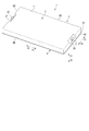
- FIG. 1 is a perspective view schematically showing an example of a secondary battery manufactured by the manufacturing method according to the first embodiment.
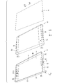
- FIG. 2 is a perspective view schematically showing the secondary battery of FIG. 1 with the first exterior member, the second exterior member, and the electrode group disassembled with respect to each other.
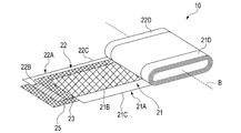
- FIG. 3 is a schematic view illustrating the configuration of the electrode group of the secondary battery of FIG.
- FIG. 4 is a schematic view showing an electrical connection configuration of the electrode group to the positive electrode terminal (negative electrode terminal) in the secondary battery of FIG.
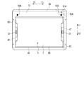
- FIG. 5 is a schematic view showing the secondary battery of FIG. 1 as viewed from the side where the bottom wall of the first exterior member is located in the thickness direction.
- FIG. 1 is a perspective view schematically showing an example of a secondary battery manufactured by the manufacturing method according to the first embodiment.
- FIG. 2 is a perspective view schematically showing the secondary battery of FIG. 1 with the first exterior member, the second exterior member, and the electrode group disassembled with respect to each other.
- FIG. 3
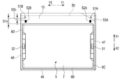
- FIG. 6 is a schematic view showing a state in which the second exterior member is disposed to face the flange at the time of production of the secondary battery by the production method according to the first embodiment.
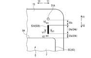
- FIG. 7A is a schematic view showing the configuration of the convex portion and the vicinity thereof in the state of FIG. 6 at the time of manufacture in the first example of the first embodiment.
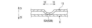
- FIG. 7B is a cross-sectional view schematically showing a V1-V1 cross section of FIG. 7A.
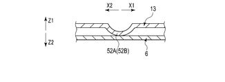
- FIG. 7C is a cross-sectional view schematically showing a V2-V2 cross section of FIG. 7A.
- FIG. 8A is a schematic view showing a configuration of a convex portion and the vicinity thereof in a state of FIG.
- FIG. 8B is a cross-sectional view schematically showing a V3-V3 cross section of FIG. 8A.
- FIG. 9A is a schematic view showing a configuration of a convex portion and the vicinity thereof in a state of FIG. 6 at the time of manufacture in a third example of the first embodiment.
- FIG. 9B is a cross-sectional view schematically showing a V4-V4 cross section of FIG. 9A.
- FIG. 9C is a cross-sectional view schematically showing a V5-V5 cross section of FIG. 9A.
- FIG. 10 is a schematic view showing a state in which the flange and the second exterior member are airtightly welded in a partial range in the circumferential direction of the opening from the state of FIG.
- FIG. 11 is a schematic view showing a state in which the electrolytic solution is injected into the storage space from the state of FIG. 10 and the flange and the second exterior member are airtightly welded in the range not welded in the circumferential direction of the opening. is there.
- FIG. 12 is a schematic view showing a state in which gas is discharged from the unsealing hole in the vicinity of one of the convex portions to the outside of the exterior portion in the state of FIG. FIG.
- FIG. 13 is a schematic view showing a state in which a welded portion is formed between the opening and the convex portion from which the gas is discharged, from the state of FIG. 14 is a schematic view showing a state in which an opening hole different from the opening hole from which the gas is discharged in FIG. 12 is formed in the vicinity of the other of the convex portions from the state of FIG.
- FIG. 15 is a schematic view showing a state in which gas is discharged from the opening hole formed in FIG. 14 from the state of FIG. 14 and a welded portion is formed between the opening hole and the convex portion.
- FIG. 16 is a schematic view showing a state in which a weld is formed between the edge of the opening and the projection from the state of FIG. FIG.
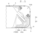
- FIG. 17 is a cross-sectional view schematically showing a convex portion and the vicinity thereof in a state in which the internal pressure inside the exterior portion is lower than the external pressure outside the exterior portion in the first embodiment.
- FIG. 18 is a cross-sectional view schematically showing a convex portion and its neighborhood in a state in which the internal pressure inside the exterior portion is lower than the external pressure outside the exterior portion in the second embodiment.
- FIG. 19 is a schematic view showing a system used for verification regarding a pressure reduction state of the storage space at the time of manufacturing the secondary battery by the manufacturing method according to the first embodiment.
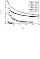
- FIG. 20 is a schematic diagram showing measurement results of temporal changes in the degree of vacuum of a storage space of a subject in verification using the system of FIG.
- FIG. 1 shows an example of a secondary battery 1 manufactured by the manufacturing method according to the first embodiment.
- the secondary battery 1 is, for example, a non-aqueous electrolyte battery.
- the secondary battery 1 includes an exterior portion 3.
- the exterior part 3 is formed of a first exterior member 5 and a second exterior member 6.
- Each of exterior members 5 and 6 is formed of stainless steel.
- the first exterior member 5 is formed in a bottomed tubular shape.
- the first exterior member 5 has a bottom wall 7 and four side walls 8A to 8D, and is formed in a substantially rectangular cylindrical shape with a bottom.
- the storage space 11 is defined by the bottom wall 7 and the side walls 8A to 8D.
- the electrode group 10 is stored in the storage space 11.
- FIG. 2 shows the first exterior member 5, the second exterior member 6 and the electrode group 10 in a disassembled state with respect to each other.
- the storage space 11 has an opening 12 on the side opposite to the bottom wall 7.
- a thickness direction (direction indicated by the arrow Z1 and the arrow Z2) perpendicular to or substantially perpendicular to the lateral direction is defined.
- the side walls 8A and 8B are disposed longitudinally separated from each other with the storage space 11 therebetween, and the sidewalls 8C and 8D are disposed laterally separated from each other with the storage space 11 interposed therebetween. Be done. Further, each of the side walls 8A to 8D extends from the bottom wall 7 toward the opening 12 along the thickness direction, and the storage space 11 extends toward the one side in the thickness direction (arrow Z2 side) in the opening 12 Open.
- a flange 13 is provided at a position opposite to the bottom wall 7.
- the flange 13 protrudes outward, ie, away from the opening 12, with respect to the side walls 8A to 8D. Then, the flange 13 defines the edge 15 of the opening 12 over the entire circumference of the opening 12 in the circumferential direction.
- the second exterior member 6 is formed in a plate shape, and is, for example, a substantially rectangular plate member. The second exterior member 6 is disposed to face the flange 13 and faces the flange 13 from the side where the opening 12 is opened.
- the second exterior member 6 protrudes outward with respect to the side walls 8A to 8D, that is, away from the opening 12, over the entire circumferential direction of the opening 12. For this reason, in the region outside the edge 15 of the opening 12, the second exterior member 6 faces the flange 13 over the entire circumferential direction of the opening 12. Further, the second exterior member 6 is disposed in a state where the thickness direction of the plate-like second exterior member 6 matches or substantially matches the thickness direction of the secondary battery 1. As described above, the second exterior member 6 closes the opening 12 of the storage space 11 by arranging the second exterior member 6.
- the distance from the bottom wall 7 to the opening 12 is much smaller than the distance between the side walls 8A and 8B and the distance between the side walls 8C and 8D, respectively.
- the dimension in the thickness direction is much smaller than each of the dimension in the longitudinal direction and the dimension in the lateral direction.
- the distance between the side walls 8A and 8B is smaller than the distance between the side walls 8C and 8D
- the dimension in the vertical direction is smaller than the dimension in the horizontal direction. Small.
- the first exterior member 5 has a thickness of 0.02 mm or more and 0.3 mm or less in each of the bottom wall 7, the side walls 8A to 8D, and the flange 13.
- the plate-like second exterior member 6 has a thickness of 0.02 mm or more and 0.3 mm or less.
- FIG. 3 is a diagram for explaining the configuration of the electrode group 10.
- the electrode group 10 is formed in, for example, a flat shape, and includes a positive electrode 21, a negative electrode 22, and separators 23 and 25.
- the positive electrode 21 includes a positive electrode current collector foil 21A as a positive electrode current collector, and a positive electrode active material containing layer 21B supported on the surface of the positive electrode current collector foil 21A.
- the positive electrode current collector foil 21A is, for example, an aluminum foil or an aluminum alloy foil, and has a thickness of about 10 ⁇ m to 20 ⁇ m.
- a slurry containing a positive electrode active material, a binder, and a conductive agent is applied to the positive electrode current collector foil 21A.
- the positive electrode active material examples include, but are not limited to, oxides, sulfides, polymers, and the like that can occlude and release lithium. Further, from the viewpoint of obtaining a high positive electrode potential, as the positive electrode active material, lithium manganese composite oxide, lithium nickel composite oxide, lithium cobalt composite oxide, lithium iron phosphate and the like are preferably used.
- the negative electrode 22 includes a negative electrode current collector foil 22A as a negative electrode current collector, and a negative electrode active material containing layer 22B supported on the surface of the negative electrode current collector foil 22A.
- the negative electrode current collector foil 22A is an aluminum foil, an aluminum alloy foil, a copper foil or the like, and has a thickness of about 10 ⁇ m to 20 ⁇ m.
- a slurry containing a negative electrode active material, a binder, and a conductive agent is applied to the negative electrode current collector foil 12A.
- the negative electrode active material is not particularly limited, and examples thereof include metal oxides capable of inserting and extracting lithium ions, metal sulfides, metal nitrides, and carbon materials.
- a negative electrode active material a substance having a lithium ion absorption / discharge potential of 0.4 V or more with respect to the metal lithium potential, that is, a lithium ion absorption / discharge potential of 0.4 V (vs. Li + / Li) or more It is preferably a substance.
- the negative electrode active material having such a lithium ion storage and release potential an alloy reaction between aluminum or an aluminum alloy and lithium is suppressed. Therefore, aluminum and a component related to the negative electrode current collector foil 22A and the negative electrode 22 Aluminum alloy can be used.
- a negative electrode active material having a lithium ion storage and release potential of 0.4 V vs.
- Li + / Li or more, for example, titanium oxide, lithium titanium composite oxide such as lithium titanate, tungsten oxide, amorphous tin Examples thereof include oxides, niobium-titanium composite oxides, tin silicon oxides, and silicon oxides. It is particularly preferable to use lithium titanium composite oxides as the negative electrode active material.
- the carbon material which occludes-discharges lithium ion as a negative electrode active material, it is good for the negative electrode current collection foil 22A to use copper foil.
- the carbon material used as the negative electrode active material has a lithium ion storage and release potential of about 0 V (vs. Li + / Li).
- the aluminum alloy used for the positive electrode current collector foil 21A and the negative electrode current collector foil 22A desirably contains one or more elements selected from Mg, Ti, Zn, Mn, Fe, Cu and Si.
- the purity of aluminum and aluminum alloy can be 98% by weight or more, preferably 99.99% by weight or more.
- pure aluminum having a purity of 100% can be used as a material of the positive electrode current collector and / or the negative electrode current collector.
- the content of transition metals such as nickel and chromium in aluminum and aluminum alloys is preferably 100 ppm by weight or less (including 0 ppm by weight).
- positive electrode current collection tab 21D is formed of one long edge 21C and its neighborhood part. In the present embodiment, the positive electrode current collection tab 21D is formed over the entire length of the long edge 21C. In the positive electrode current collection tab 21D, the positive electrode active material containing layer 21B is not supported on the surface of the positive electrode current collection foil 21A. Further, in the negative electrode current collector foil 22A, the negative electrode current collector tab 22D is formed by one long edge 22C and the vicinity thereof. In the present embodiment, the negative electrode current collection tab 22D is formed over the entire length of the long edge 22C. In the negative electrode current collection tab 22D, the negative electrode active material containing layer 22B is not supported on the surface of the negative electrode current collection foil 22A.
- Each of the separators 23 and 25 is formed of an electrically insulating material, and electrically insulates between the positive electrode 21 and the negative electrode 22.
- Each of the separators 23 and 25 may be a sheet or the like separate from the positive electrode 21 and the negative electrode 22, or may be integrally formed with one of the positive electrode 21 and the negative electrode 22.
- the separators 23 and 25 may be formed of an organic material, may be formed of an inorganic material, or may be formed of a mixture of an organic material and an inorganic material. Examples of the organic material forming the separators 23 and 25 include engineering plastic and super engineering plastic.
- Examples of engineering plastics include polyamide, polyacetal, polybutylene terephthalate, polyethylene terephthalate, syndiotactic polystyrene, polycarbonate, polyamide imide, polyvinyl alcohol, polyvinylidene fluoride and modified polyphenylene ether.
- Examples of super engineering plastics include polyphenylene sulfide, polyetheretherketone, liquid crystal polymer, polyvinylidene fluoride, polytetrafluoroethylene (PTFE), polyether nitrile, polysulfone, polyacrylate, polyether imide, thermoplastic polyimide and the like.
- oxides for example, aluminum oxide, silicon dioxide, magnesium oxide, phosphorus oxide, calcium oxide, iron oxide, titanium oxide
- nitrides for example, boron nitride, Aluminum nitride, silicon nitride, barium nitride
- winding axis B of positive electrode 21, negative electrode 22, and separators 23 and 25 is in a state in which each of separators 23 and 25 is sandwiched between positive electrode active material-containing layer 21B and negative electrode active material-containing layer 22B.
- the positive electrode 21, the separator 23, the negative electrode 22, and the separator 25 are wound in a stacked state in this order.
- the positive electrode current collection tab 21D of the positive electrode current collector foil 21A protrudes to one side in the direction along the winding axis B with respect to the negative electrode 22 and the separators 23 and 25.
- the negative electrode current collection tab 22D of the negative electrode current collection foil 22A protrudes to the side opposite to the side where the positive electrode current collection tab 21D protrudes in the direction along the winding axis B with respect to the positive electrode 21 and the separators 23 and 25.
- the electrode group 10 is disposed such that the winding axis B is parallel or substantially parallel to the lateral direction of the secondary battery 1.
- the electrode group 10 is impregnated with an electrolytic solution (not shown) in the storage space 11.
- an electrolytic solution (not shown) in the storage space 11.
- a non-aqueous electrolytic solution is used as the electrolytic solution, and for example, a non-aqueous electrolytic solution prepared by dissolving the electrolyte in an organic solvent is used.
- lithium perchlorate LiClO 4
- LiPF 6 lithium hexafluorophosphate
- LiBF 4 lithium tetrafluoroborate
- LiAsF 6 lithium hexafluoride arsenic
- lithium salts such as lithium trifluoromethanesulfonate (LiCF 3 SO 3 ) and bistrifluoromethylsulfonylimide lithium [LiN (CF 3 SO 2 ) 2 ], and mixtures thereof.
- organic solvents such as propylene carbonate (PC), ethylene carbonate (EC) and vinylene carbonate; linear carbonates such as diethyl carbonate (DEC), dimethyl carbonate (DMC) and methyl ethyl carbonate (MEC); Cyclic ethers such as (THF), 2-methyltetrahydrofuran (2MeTHF), and dioxolane (DOX); linear ethers such as dimethoxyethane (DME) and diethoxyethane (DEE); ⁇ -butyrolactone (GBL), acetonitrile (AN) And sulfolane (SL). These organic solvents are used alone or as a mixed solvent.
- PC propylene carbonate
- EC ethylene carbonate
- MEC methyl ethyl carbonate
- Cyclic ethers such as (THF), 2-methyltetrahydrofuran (2MeTHF), and dioxolane (DOX)
- linear ethers such as dimethoxy
- a gel non-aqueous electrolyte in which a non-aqueous electrolyte and a polymer material are complexed is used as the electrolyte.
- the aforementioned electrolyte and organic solvent are used.
- PVdF polyvinylidene fluoride
- PAN polyacrylonitrile
- PEO polyethylene oxide
- solid electrolytes such as a polymer solid electrolyte and an inorganic solid electrolyte are provided as the non-aqueous electrolyte instead of the electrolytic solution.
- the separators 23 and 25 may not be provided in the electrode group 10.
- a solid electrolyte is sandwiched between the positive electrode 21 and the negative electrode 22. Therefore, in the present embodiment, the positive electrode 21 and the negative electrode 22 are electrically insulated by the solid electrolyte.
- an inclined surface 26 is provided on the outer surface of the first exterior member 5 between the bottom wall 7 and the side wall 8C. Further, an inclined surface 27 is provided on the outer surface of the first exterior member 5 between the bottom wall 7 and the side wall 8D.
- the positive electrode terminal 31 is attached to the inclined surface 26, and the negative electrode terminal 32 is attached to the inclined surface 27.
- Each of the terminals 31 and 32 is formed of a conductive material, for example, any of aluminum, copper and stainless steel.
- FIG. 4 shows an electrical connection configuration of the electrode group 10 to the positive electrode terminal 31 (negative electrode terminal 32).
- the positive electrode current collection tab 21D of the electrode group 10 is bundled by welding such as ultrasonic welding, and the bundle of the positive electrode current collection tab 21D is connected to the positive electrode backup lead 35 by welding such as ultrasonic welding. Be done.
- the positive electrode backup lead 35 is connected to the positive electrode lead 36 by welding such as ultrasonic welding, and the positive electrode lead 36 is connected to the positive electrode terminal lead 37 by welding such as ultrasonic welding.
- the positive electrode terminal lead 37 is connected to the positive electrode terminal 31.
- Each of the positive electrode backup lead 35, the positive electrode lead 36, and the positive electrode terminal lead 37 is formed of a conductive material.
- the positive electrode current collection tab 21D is electrically connected to the positive electrode terminal 31 via the positive electrode backup lead 35, the positive electrode lead 36 and the positive electrode terminal lead 37.
- Each of the positive electrode current collection tab 21D, the positive electrode backup lead 35, the positive electrode lead 36, the positive electrode terminal lead 37, and the positive electrode terminal 31 is electrically insulated from the exterior members 5 and 6.
- the negative electrode current collection tab 22D of the electrode group 10 is bundled by welding such as ultrasonic welding, and the bundle of the negative electrode current collection tab 22D is connected to the negative electrode backup lead 41 by welding such as ultrasonic welding.
- the negative electrode backup lead 41 is connected to the negative electrode lead 42 by welding such as ultrasonic welding, and the negative electrode lead 42 is connected to the negative electrode terminal lead 43 by welding such as ultrasonic welding. Then, the negative electrode terminal lead 43 is connected to the negative electrode terminal 32.
- Each of the negative electrode backup lead 41, the negative electrode lead 42, and the negative electrode terminal lead 43 is formed of a conductive material.
- the negative electrode current collection tab 22D is electrically connected to the negative electrode terminal 32 via the negative electrode backup lead 41, the negative electrode lead 42, and the negative electrode terminal lead 43.
- Each of the negative electrode current collection tab 22D, the negative electrode backup lead 41, the negative electrode lead 42, the negative electrode terminal lead 43, and the negative electrode terminal 32 is electrically insulated from the exterior members 5 and 6.
- FIG. 5 shows the secondary battery 1 as viewed from the side where the bottom wall 7 of the first exterior member 5 is located in the thickness direction.
- welds 45 to 48 for airtightly welding the flange 13 and the second exterior member 6 are formed.
- Each of the welds 45 to 48 is provided outside the edge 15 of the opening 12, that is, on the side away from the opening 12 with respect to the edge 15.
- the welding portion 45 is formed in the flange 13 and the second exterior member 6 so as to protrude outward from the side wall 8A in the longitudinal direction, and is extended along the lateral direction.
- the welding portion 46 is formed at a portion projecting outward from the side wall 8B in the longitudinal direction in the flange 13 and the second exterior member 6, and is extended along the lateral direction.
- the welding portion 47 is formed in the flange 13 and the second exterior member 6 so as to protrude outward from the side wall 8C in the lateral direction, and is extended along the longitudinal direction.
- the welding portion 48 is formed at a portion projecting outward from the side wall 8D in the lateral direction in the flange 13 and the second exterior member 6, and is extended along the longitudinal direction.
- Welded parts 45 to 48 are indicated by broken lines in the view of secondary battery 1 in FIG. 5 etc. as viewed from one side in the thickness direction.
- the welding portion 45 is continuous with the welding portion 47 at one end, and is continuous with the welding portion 48 at the other end.
- the welding portion 46 is continuous with the welding portion 47 at one end, and is continuous with the welding portion 48 at the other end. Therefore, the flanges 13 and the second exterior member 6 are airtightly welded along the entire circumferential direction of the opening 12 by the welding portions 45 to 48. Therefore, the storage space 11 in which the electrode group 10 is stored is sealed from the exterior of the exterior 3 by the welds 45 to 48.
- the welded portions 45 to 48 for example, the flange 13 and the second exterior member 6 are welded by resistance seam welding. Since resistance seam welding is performed, cost can be suppressed as compared with laser welding and the like, and airtightness between the flange 13 and the second exterior member 6 is high.
- the first exterior member 5 is formed of stainless steel. At this time, the first exterior member 5 is formed such that the storage space 11 is defined by the bottom wall 7 and the side walls 8A to 8D, and the storage space 11 has an opening 12 on the opposite side to the bottom wall 7. . Moreover, the 1st exterior member 5 is formed in the thickness of 0.02 mm or more and 0.3 mm or less.
- the flange 13 is formed at a portion of the first exterior member 5 opposite to the bottom wall 7. At this time, the flange 13 protrudes to the side away from the opening 12 with respect to the side walls 8A to 8D, and the flange 13 defines the edge 15 of the opening 12 over the entire circumferential direction of the opening 12 Is formed.
- the second exterior member 6 is formed of stainless steel. In one embodiment, the second exterior member 6 is formed in a plate shape. Moreover, the 2nd exterior member 6 is formed in the thickness of 0.02 mm or more and 0.3 mm or less.
- the electrode group 10 including the positive electrode 21 and the negative electrode 22 is formed. In one embodiment, the electrode group 10 is formed by winding the positive electrode 21, the negative electrode 22, and the separators 23 and 25 as described above. When the exterior members 5 and 6 and the electrode group 10 are formed, the electrode group 10 is disposed in the storage space 11. In one embodiment, in the housing space 11, the winding axis B is parallel or substantially parallel to the lateral direction of the secondary battery 1 in the storage space 11, in which the positive electrode 21, the negative electrode 22, and the separators 23 and 25 are wound. Place in the following condition.
- the positive electrode current collection tab 21D of the electrode group 10 is electrically connected to the positive electrode terminal 31 via the positive electrode backup lead 35, the positive electrode lead 36 and the positive electrode terminal lead 37.
- the negative electrode current collection tab 22D of the electrode group 10 is electrically connected to the negative electrode terminal 32 through the negative electrode backup lead 41, the negative electrode lead 42, and the negative electrode terminal lead 43.
- an insulating member is provided which electrically insulates each of the positive electrode current collection tab 21D, the positive electrode backup lead 35, the positive electrode lead 36, the positive electrode terminal lead 37, and the positive electrode terminal 31 from the package members 5 and 6.
- an insulating member is provided which electrically insulates each of the negative electrode current collection tab 22D, the negative electrode backup lead 41, the negative electrode lead 42, the negative electrode terminal lead 43, and the negative electrode terminal 32 from the package members 5 and 6.
- FIG. 6 shows a state in which the second exterior member 6 is disposed to face the flange 13 when the secondary battery 1 is manufactured.
- FIG. 6 is a view seen from the side where the bottom wall 7 of the first exterior member 5 is located.
- the second exterior member 6 can be formed on the side walls 8A to 8D over the entire circumference of the opening 12 in the circumferential direction. On the other hand, it projects to the side away from the opening 12.
- the second exterior member 6 disposed so as to face the flange 13 over the entire circumference of the opening 12 in the circumferential direction. Further, in the present embodiment, the second exterior member 6 is made to face the flange 13 in a state where the thickness direction of the plate-like second exterior member 6 matches or substantially matches the thickness direction of the secondary battery 1. .
- the opening hole (first opening hole) 51 ⁇ / b> A is formed in the flange 13 in the formation of the flange 13 or in the second exterior member 6 in the formation of the second exterior member 6.
- the opening hole 51A is formed.
- the opening hole 51A is formed in one of the flange 13 and the second exterior member 6.
- the opening hole 51A is formed to have a diameter ⁇ a.
- the diameter ⁇ a is, for example, about 1 mm.
- the convex portions 52 A and 52 B are formed on the flange 13 in the formation of the flange 13, or the convex portions 52 A and 52 B on the second exterior member 6 in the formation of the second exterior member 6.
- the convex portions 52A and 52B are respectively formed on one of the flange 13 and the second exterior member 6.
- the convex portion (first convex portion) 52A is formed in the vicinity of the opening hole 51A.
- the convex portions 52A, 52B are formed at positions separated from each other.
- the opening hole 51 ⁇ / b> A and the convex portions 52 ⁇ / b> A and 52 ⁇ / b> B are disposed outside the edge 15 of the opening 12.
- each of the convex portions 52A and 52B is the other of the flange 13 and the second exterior member 6, that is, the flange 13 and the second exterior Of the portions, the protrusions 52A and 52B project toward one side where the protrusions 52A and 52B are not provided.
- the second exterior member 6 is made to face the flange 13 in a state in which the projecting direction of the convex portions 52A and 52B matches or substantially matches the thickness direction of the secondary battery 1.
- the second exterior member 6 is attached to the flange 13 in a state where the flanges 13 are provided with the convex portions 52A and 52B and each of the convex portions 52A and 52B protrudes toward the second exterior member 6. Let them face each other.
- the flange 13 or the second exterior member 6 can be opened at a protruding portion outward in the longitudinal direction from the side wall 8A.
- the holes 51A and the convex portions 52A and 52B are located.
- convex part (the 1st convex part) 52A is located in the end by the side near side wall 8C about the horizontal direction
- convex part (the 2nd convex part) 52B is the side near the side wall 8D about the horizontal direction Located at the end of the Therefore, in a state where the second exterior member 6 is disposed to face the flange 13, the convex portion 52 ⁇ / b> B is located apart from the opening hole 51 ⁇ / b> A and the convex portion 52 ⁇ / b> A in the lateral direction of the secondary battery 1.
- the convex portions 52A and 52B are shown in black.
- the opening hole (first opening hole) 51 ⁇ / b> A is arranged at a distance D1 a from the edge 15 of the opening 12.
- the distance D1a is, for example, about 20 mm.
- the opening hole 51A is disposed outside the projection (first projection) 52A, that is, on the side far from the opening 12 Be done.
- convex part 52A is arranged near open hole 51A. At this time, the distance D2a from the opening hole 51A to the convex portion 52A is 6 mm or less.
- the convex portion 52A is disposed at a distance D3 a from the edge 15 of the opening 12 and the convex portion 52B is at a distance from the edge 15 of the opening 12 D3b placed apart.
- the distances D3a and D3b are the same or substantially the same size with respect to each other, and each of the distances D3a and D3b is, for example, about 4 mm.
- 7A to 7C show a first embodiment of the configuration of the convex portion 52A (52B) and the vicinity thereof.
- 7A to 7C show the convex portion 52A (52B) and the vicinity thereof in the state of FIG. 6 at the time of manufacture.
- 7B shows a V1-V1 cross section of FIG. 7A
- FIG. 7C shows a V2-V2 cross section of FIG. 7A.
- the internal pressure inside the exterior 3 is the same as or substantially the same as the external pressure outside the exterior 3.
- each of the convex portions 52A and 52B is formed into a tunnel ceiling form.
- a longitudinal direction tunnel axis direction
- a width direction perpendicular or substantially perpendicular to the longitudinal direction and a direction perpendicular or substantially perpendicular to the longitudinal direction and perpendicular to the width direction
- a substantially vertical projecting direction is defined.
- the longitudinal direction of each of the convex portions 52A and 52B is made to coincide or substantially coincide with the longitudinal direction of the secondary battery 1
- the width direction of each of the convex portions 52A and 52B is the lateral direction of the secondary battery 1 Match or almost match.
- the convex portion 52A (52B) is shown in a cross section perpendicular or substantially perpendicular to the longitudinal direction, and in FIG. 7C, the convex portion 52A (52B) is parallel or substantially to the longitudinal direction It is shown in a cross section which is parallel and perpendicular to or substantially perpendicular to the width direction.
- the cross-sectional shape perpendicular or substantially perpendicular to the longitudinal direction is made uniform or substantially uniform over the entire length in the longitudinal direction. Further, in the present embodiment, the cross-sectional shape perpendicular or substantially perpendicular to the longitudinal direction of each of the convex portions 52A and 52B is formed in a substantially U shape or a substantially semicircular arc shape. Each of the convex portions 52A and 52B is formed in a dimension (one corresponding to D4a and D4b) in the longitudinal direction. The dimensions D4a and D4b are the same or substantially the same size with respect to each other, and each of the dimensions D4a and D4b is, for example, about 10 mm.
- each of the convex portions 52A and 52B is formed to have a width (one corresponding to W1a and W1b) in the width direction.
- the widths W1a and W1b are the same or substantially the same size with respect to each other, and each of the widths W1a and W1b is, for example, about 1.2 mm.
- each of convex part 52A, 52B is formed in the protrusion dimension (one side corresponding to P1a and P1b) to a protrusion end.
- the protrusion dimensions P1a and P1b are the same or substantially the same size with respect to each other, and each of the protrusion dimensions P1a and P1b is, for example, about 0.4 mm.
- FIGS. 8A and 8B show the configuration of the convex portions 52A1 and 52A2 (52B1 and 52B2) and the vicinity thereof in the state of FIG. 6 at the time of manufacture. Further, FIG. 8B shows a V3-V3 cross section of FIG. 8A.
- each of the convex portions 52A1, 52A2, 52B1 and 52B2 is formed into a tunnel ceiling shape, similarly to the convex portions 52A and 52B of the first embodiment. Therefore, the longitudinal direction, the width direction, and the projecting direction are defined in each of the convex portions 52A1, 52A2, 52B1, and 52B2. Then, the longitudinal direction of each of the convex portions 52A1, 52A2, 52B1 and 52B2 is made to coincide or almost coincide with the longitudinal direction of the secondary battery 1, and the width direction of each of the convex portions 52A1, 52A2, 52B1 and 52B2 is made secondary It matches or almost matches the lateral direction of the battery 1.
- each of the convex portions 52A1, 52A2, 52B1 and 52B2 the cross-sectional shape perpendicular or substantially perpendicular to the longitudinal direction is made uniform or substantially uniform over the entire length in the longitudinal direction. Further, in the present embodiment, the cross-sectional shape perpendicular or substantially perpendicular to the longitudinal direction of each of the convex portions 52A1, 52A2, 52B1 and 52B2 is formed in a substantially U shape or a substantially semicircular arc shape. In FIG. 8B, each of the convex portion 52A1 and the convex portion 52A2 (52B1 and 52B2) is shown in a cross section perpendicular or substantially perpendicular to the longitudinal direction.
- the convex portions (first convex portions) 52A1 and 52A2 are formed to be close to each other. That is, the convex portion 52A1 is formed in the vicinity of the convex portion 52A2. And convex part 52A1, 52A2 is formed in the state extended in parallel or substantially parallel with respect to each other. Further, the convex portions 52A1 and 52A2 are formed in a state of being aligned along a specific direction. In this embodiment, the specific direction in which the convex portions 52A1 and 52A2 are arranged is made to coincide or substantially coincide with the lateral direction of the secondary battery 1, and be perpendicular or substantially perpendicular to the longitudinal direction of the convex portions 52A1 and 52A2. .
- the convex portions 52A1 and 52A2 are formed over the same or substantially the same range with respect to each other in the longitudinal direction of the secondary battery 1. Similarly, the convex portions (second convex portions) 52B1 and 52B2 are formed to be close to each other. That is, the convex portion 52B1 is formed in the vicinity of the convex portion 52B2. And convex part 52B1, 52B2 is formed in the state extended in parallel or substantially parallel with respect to each other. Further, the convex portions 52B1 and 52B2 are formed in a state of being aligned along a specific direction.
- the specific direction in which the convex portions 52B1 and 52B2 are arranged is made to coincide or substantially coincide with the lateral direction of the secondary battery 1, and be perpendicular or substantially perpendicular to the longitudinal direction of the convex portions 52B1 and 52B2. .
- the convex portions 52B1 and 52B2 are formed over the same or substantially the same range with respect to each other in the longitudinal direction of the secondary battery 1.
- Each of the convex portions 52A1, 52A2, 52B1 and 52B2 is formed in a dimension (corresponding one of D5a, D6a, D5b, D6b) in the longitudinal direction.
- the dimensions D5a, D6a, D5b, and D6b are the same or substantially the same size with respect to one another, and each of the dimensions D5a, D6a, D5b, and D6b is, for example, about 10 mm.
- each of the convex portions 52A1, 52A2, 52B1 and 52B2 is formed in a width (one corresponding to W2a, W3a, W2b, W3b) in the width direction.
- the widths W2a, W3a, W2b, and W3b have the same or substantially the same size with respect to one another, and the widths W2a, W3a, W2b, and W3b each are, for example, about 1.2 mm.
- each of convex part 52A1, 52A2, 52B1, 52B2 is formed in the protrusion dimension (corresponding one of P2a, P3a, P2b, P3b) to a protrusion end.
- the protrusion dimensions P2a, P3a, P2b, and P3b are the same or substantially the same size as one another, and each of the protrusion dimensions P2a, P3a, P2b, and P3b is, for example, about 0.6 mm.
- the convex portions 52A1 and 52A2 are formed so as to be separated from each other by a predetermined distance W4a in the predetermined direction in which the convex portions 52A1 and 52A2 are arranged, that is, the lateral direction of the secondary battery 1 in this embodiment.
- the convex portions 52B1 and 52B2 are formed apart from each other by a predetermined distance W4b in the predetermined direction in which the convex portions 52B1 and 52B2 are arranged, in this embodiment, in the lateral direction of the secondary battery 1.
- the separation distances W4a and W4b are the same or substantially the same size with respect to each other, and each of the widths W4a and W4b is, for example, about 0.6 mm.
- each of the convex portions 52A and 52B is formed in a dome shape.
- or FIG. 9C show the structure of convex part 52A (52B) in the state of FIG. 6 at the time of manufacture, and its vicinity.
- 9B shows a V4-V4 cross section of FIG. 9A
- FIG. 9C shows a V5-V5 cross section of FIG. 9A.
- the cross section of FIG. 9B and the cross section of FIG. 9C are cross sections parallel or substantially parallel to the projecting direction of the convex portion 52A (52B), and are perpendicular or substantially perpendicular to each other.
- each of the convex portions 52A and 52B is formed in a dome shape.
- vertical to the longitudinal direction of each secondary battery 1 of convex part 52A, 52B is formed in substantially U shape or substantially semicircular arc shape.
- vertical to the horizontal direction of each secondary battery 1 of convex part 52A, 52B is formed in substantially U shape or substantially semicircular arc shape. That is, in each of the convex portions 52A and 52B, the cross-sectional shape is formed in a U shape or a substantially semicircular arc shape in any cross section parallel or substantially parallel to the projecting direction.
- the flange 13 and the second The exterior member 6 is airtightly welded.
- the welds 46 to 48 are formed before injecting the electrolytic solution into the storage space 11.
- welds 46 to 48 are formed by resistance seam welding.
- the flange 13 and the second exterior member 6 are not welded in a partial range in the circumferential direction of the opening 12. For this reason, in the state of FIG. 10, the welded portion is not formed in the range in which the side wall 8A extends in the circumferential direction of the opening 12. Then, in the state of FIG.
- the electrolytic solution is injected into the storage space 11 from a portion where the flange 13 and the second exterior member 6 are not welded. At this time, the electrolytic solution is injected from any part of the range in which the side wall 8A is extended in the circumferential direction of the opening 12. The electrolytic solution is injected into the storage space 11 through the gap between the flange 13 and the second exterior member 6.
- the flange 13 and the second exterior member 6 are airtightly welded by resistance seam welding in a range in which welding is not performed in the circumferential direction of the opening. Thereby, the welding part 50 is formed.
- the welded portion 50 is formed at a portion projecting outward from the side wall 8 ⁇ / b> A in the longitudinal direction.
- the weld 50 is formed such that one end is continuous with the weld 47 and the other end is continuous with the weld 48.
- the welding portion 50 is formed outside the opening hole 51A and the convex portions 52A and 52B, that is, on the side away from the opening 12.
- welding portion 50 flanges 13 and second exterior member 6 are airtightly welded all around the circumferential direction of opening 12 by welding portions 46 to 48, 50. . That is, welds (first welds) 46 to 48, 50 for sealing the flange 13 and the second exterior member 6 airtightly are formed over the entire circumference in the circumferential direction of the opening 12. Further, by forming the welding portion 50, the inside (the storage space 11) of the exterior portion 3 communicates with the outside of the exterior portion 3 only with the opening hole 51A. In the view of the secondary battery 1 shown in FIG. 11 and the like as viewed from one side in the thickness direction, the welded portion 50 is indicated by a broken line.
- the inside and the outside of the exterior portion 3 communicate with each other in the opening hole 51A.
- the internal pressure (pressure of the storage space 11) inside the exterior 3 is the same as or substantially the same as the external pressure outside the exterior 3.
- the flange 13 and the second exterior are spread over the whole or most of the area inside the welds 46 to 48, 50 and outside the edge 15 of the opening 12 A gap is formed between the member 6 and the member 6.
- the flange 13 is in a region other than the projecting ends of the protrusions 52A, 52B, There is a gap between the second exterior member 6 and the second exterior member 6 so that the second exterior member 6 is not in close contact.
- the operation of injecting the electrolytic solution may not be necessary.
- the welds 46 to 48 may be formed after the welds 50 are formed.
- the flange 13 and the second exterior member 6 are welded airtight all around the circumferential direction of the opening 12 by the welds (first welds) 46 to 48, 50. Ru.
- the gas of the storage space 11 will be discharged
- the suction pad 55 is attached to the outer surface of the exterior part 3 in the opening hole (1st opening position) 51A.
- the suction pad 55 is connected to a pump 57 such as a vacuum pump via a suction tube 56.
- a valve 61 and a vacuum regulator 62 are disposed in the suction path between the pump 57 and the suction pad 55.
- the pump 57 is driven to open the valve 61.
- gas flows from the storage space 11 to the opening hole 51A through the gap between the flange 13 and the second exterior member 6.
- the gas is sucked into the inside of the suction tube 56 from the opening hole 51A, and the gas flows toward the pump 57 through the inside of the suction tube 56.
- the discharge from the opening hole 51A is performed under an environment where the dew point temperature is -50.degree. C. or less.
- the gas is discharged from the opening hole 51A to the outside of the exterior part 3 and the internal pressure inside the exterior part 3 such as the pressure of the storage space 11 decreases to a certain degree, as shown in FIG.
- the flange 13 and the second exterior member 6 are airtightly welded between the opening position 51A and the convex portion 52A. That is, the welded portion 53A is formed between the opening hole 51A and the convex portion 52A.
- Weld portion 53A is formed to be inclined with respect to the longitudinal direction and the lateral direction of secondary battery 1.
- the welding portion 53A is formed such that one end is continuous with the welding portion 50 and the other end is continuous with the welding portion 47.
- the path of the gas is blocked between the opening hole (first opening position) 51A and the convex portion (first convex portion) 52A.
- the welded portion 53A is formed by, for example, resistance seam welding, similarly to the welded portions 46 to 48, 50. Moreover, in the figure which looked at the secondary battery 1 of FIG. 13 grade
- welds 53A welds 46 to 48, 50, 53A at the inner side with respect to opening hole 51A, flange 13 and the second
- the exterior member 6 is airtightly welded. Thereby, the storage space 11 in which the electrode group 10 is stored is sealed from the outside of the exterior 3.
- the welding portion 53A When the welding portion 53A is formed, the portions outside the welding portions 46 to 48 in the flange 13 and the second exterior member 6 are cut. Then, the secondary battery 1 is charged (first charge) and aged. Thereby, gas is generated in the storage space 11 in which the electrode group 10 is stored. When the aging is performed as described above, it is necessary to discharge the gas generated by the aging to the outside of the exterior portion 3.
- the aging temperature is desirably in the range of 70 ° C. or more and 90 ° C. or less.
- the opening hole 51B is formed in one of the flange 13 and the second exterior member 6.
- the opening hole 51 ⁇ / b> B is formed on the inner side with respect to the weld portion (first weld portion) 50, that is, on the side closer to the opening 12.
- the opening hole 51B is formed on the outer side of the convex portion 52B, that is, on the side far from the opening 12. That is, the opening hole 51B is formed between the welding portion 50 and the convex portion 52B. At this time, the opening hole 51B is formed to have a diameter ⁇ b.
- the diameter ⁇ b of the opening hole 51B is the same or substantially the same size as the diameter ⁇ a of the opening hole 51A, and is, for example, about 1 mm.
- the opening hole (second opening hole) 51B is formed at a position separated from the edge 15 of the opening 12 by the distance D1b.
- the distance D1b has the same or substantially the same size as the distance D1a, and is, for example, about 20 mm.
- the worker forms the opening hole 51B in the vicinity of the convex portion 52B. At this time, the opening hole 51B is formed in a state where the distance D2b from the convex portion 52B to the opening hole 51B is 6 mm or less.
- the opening hole 51B is formed at a position away from the opening hole 51A and the convex portion 52A in the lateral direction of the secondary battery 1.
- a through-hole is first formed in both the flange 13 and the 2nd exterior member 6. As shown in FIG. Then, one of the two through holes is airtightly closed. Thereby, the unsealed one of the two through holes is used as the opening hole 51B.
- the gas in the storage space 11 is discharged from the opening hole 51B to the outside of the exterior part 3. That is, from the unsealing position (second unsealing position) in the vicinity of the convex portion 52B between the weld portion (first welded portion) 50 and the convex portion (second convex portion) 52B, the storage space 11 Exhaust the gas. At this time, the gas is discharged from the opening hole 51B using the suction pad 55, the suction tube 56, the pump 57, the valve 61, the vacuum regulator 62, etc., similarly to the discharge of the gas from the opening hole (first opening position) 51A. Discharge.
- the flange 13 and the second exterior member 6 are airtightly welded between the unsealing position 51B and the convex portion 52B. That is, the welded portion 53B is formed between the opening hole 51B and the convex portion 52B.
- Welded portion 53 B is formed to be inclined with respect to the longitudinal direction and the lateral direction of secondary battery 1.
- the welding portion 53 ⁇ / b> B is formed such that one end is continuous with the welding portion 50 and the other end is continuous with the welding portion 48.
- the path of gas is blocked between the opening hole (second opening position) 51B and the convex portion (second convex portion) 52B.
- the welded portion 53B is formed by, for example, resistance seam welding, similarly to the welded portions 46 to 48, 50, 53B.
- the welding part 53B is shown with a broken line.
- welds 53B By forming welds 53B, flanges 13 are provided along the entire circumferential direction of opening 12 by welds 46 to 48, 50, 53A, 53B at a portion inside the opening holes 51A, 51B. And the second exterior member 6 are airtightly welded. Thereby, the storage space 11 in which the electrode group 10 is stored is sealed again from the outside of the exterior 3. Once the weld portion 53B is formed, the capacity of the secondary battery 1 is confirmed.
- the flange 13 and the second exterior member 6 are airtightly welded on the inner side of the convex portions 52A and 52B to form a welded portion (second welded portion) 45.
- the welded portion 45 is formed after both the discharge of gas from the opening hole (first opening position) 51A and the discharge of gas from the opening hole (second opening position) 51B.
- the weld 45 is formed on the outside of the edge 15 of the opening 12 by resistance seam welding.
- the weld 45 is formed such that one end is continuous with the weld 47 and the other end is continuous with the weld 48.
- the welding portion 45 is formed in the flange 13 and the second exterior member 6 so as to project outward from the side wall 8A in the longitudinal direction, and is extended along the lateral direction of the secondary battery 1 .
- a welded portion (second welded portion) 45 By forming a welded portion (second welded portion) 45, the edge 15 of the opening 12 and the convex portion (first convex portion) 52A, and the edge 15 of the opening 12 and the convex portion (second The gas path is blocked between the projection 52B and the projection 52B.
- part outside the welding part 50 is cut.
- opening hole (opening position) 51A, 51B and convex part 52A, 52B are removed.
- the flanges 13 and the second exterior member 6 are airtightly welded along the entire circumferential direction of the opening 12 by the welding portions 45 to 48. Therefore, the storage space 11 in which the electrode group 10 is disposed is sealed to the outside of the exterior 3 even if the portion outside the weld 50 is cut.
- the secondary battery 1 is manufactured.
- the weld 45 is not formed.
- the flanges 13 and the second exterior member 6 are airtightly welded over the entire circumference in the circumferential direction of the opening 12 by the welding portions 46 to 48, 50, 53A, 53B, and the storage space 11 faces the outside. Sealed. Further, in the present embodiment, the convex portions 52A and 52B and the opening holes 51A and 51B are provided in the manufactured secondary battery 1.
- the welding portion 45 is not formed, after the welding portion 53A is formed at the time of manufacture, the portion outside the welding portion 53A is cut in the flange 13 and the second exterior member 6. Thereby, the opening hole 51A is removed, and the opening hole 51A is not provided in the manufactured secondary battery 1.
- the weld 45 is not formed, after the weld 53B is formed at the time of manufacture, a portion outside the weld 53B is cut in the flange 13 and the second exterior member 6. Thereby, the opening hole 51B is removed, and the opening hole 51B is not provided in the manufactured secondary battery 1.
- secondary battery 1 is manufactured by cutting the portion outside weld 53A and the portion outside weld 53B during manufacturing. Both of the opening holes 51A and 51B are not provided.
- the discharge of gas from the opening hole 51A and the discharge of gas from the opening hole 51B are performed.
- the pressure of the storage space 11, that is, the internal pressure inside the exterior 3 decreases.
- the internal pressure inside the exterior part 3 is lower than the external pressure outside the exterior part 3.
- the flange 13 and the second exterior member 6 are in close contact with each other at the portion far from the convex portions 52A and 52B.
- the convex portions 52A and 52B are provided on one of the flange 13 and the second exterior member 6, and the flange 13 and the second exterior member 6 are formed of stainless steel.
- the flange 13 has a gap with respect to the second exterior member 6 in the vicinity of the protruding end of the convex portion 52A, and adheres to the second exterior member 6 do not do.
- the flange 13 has a gap with respect to the second exterior member 6 in the vicinity of the projecting end of the convex portion 52B and adheres to the second exterior member 6 do not do.
- the flange 13 abuts on the second exterior member 6 at the respective projecting ends of the convex portions 52A and 52B.
- FIG. 17 shows the convex portion 52A (52B) and the vicinity thereof in the state where the internal pressure inside the exterior portion 3 is lower than the external pressure outside the exterior portion 3 in the configuration of the first embodiment described above.
- the protrusions 52A (52B) are shown in a cross section perpendicular or substantially perpendicular to the longitudinal direction.
- the flange 13 can be used as the second exterior member 6 in the vicinity of the projecting end of each of the convex portions 52A and 52B. On the other hand, it has a gap and does not adhere to the second exterior member 6.
- the flange 13 has a second exterior in the vicinity of the projecting end of each of the convex portions 52A and 52B. There is a gap for the member 6 and it does not adhere to the second exterior member 6.
- the flange 13 is a second exterior member in the vicinity of the projecting end of each of the convex portions 52A and 52B regardless of the magnitude of the external pressure and the internal pressure. There is a gap for 6 and it does not closely contact the second exterior member 6. For this reason, even if the internal pressure becomes lower than the external pressure by suction from one of the opening holes (opening position) 51A, 51B, the path of the gas is blocked in the vicinity of each projecting end of the convex portions 52A, 52B. It is secured without.
- the gas is appropriately discharged from the opening holes 51A and 51B at the time of manufacture, and therefore, in the manufactured secondary battery 1, almost no gas remains in the inside of the exterior part 3, that is, the storage space 11. . Thereby, the secondary battery 1 having a low internal resistance and a long life is manufactured.
- FIG. 18 shows the projections 52A1 and 52A2 (52B1 and 52B2) and their parts in the state where the internal pressure inside the exterior part 3 is lower than the external pressure outside the exterior part 3 in the configuration of the second embodiment described above. Indicates the neighborhood.
- the convex portions 52A1 and 52A2 (52B1 and 52B2) are shown in a cross section perpendicular to or substantially perpendicular to the longitudinal direction. As shown in FIG.
- each of the convex portions 52A1, 52A2, 52B1, 52B2 In the vicinity of the protruding end of the flange 13, the flange 13 has a gap with respect to the second exterior member 6 and does not adhere to the second exterior member 6. For this reason, as described above, even if the internal pressure becomes lower than the external pressure, the gas reaches the unsealing hole (one corresponding to 51A, 51B) and the gas from the unsealing hole (one corresponding to 51A, 51B) Exhausted.
- the second of the flanges 13 is formed between the projecting ends of the convex portions 52A1 and 52A2.
- the clearance of the outer member 6 to the outer member 6 is maintained large.
- the convex portions 52B1 and 52B2 are close to each other, even if the internal pressure becomes lower than the external pressure, the number of flanges 13 is increased between the projecting ends of the convex portions 52B1 and 52B2. The gap between the two exterior members 6 is maintained large.
- the opening is made from the storage space 11 through the vicinity of the projecting end of the convex portion 52A1, 52A2 or the vicinity of the projecting end of the convex portion 52B1, 52B2. It is easier for the gas to flow into the holes (corresponding ones of 51A, 51B). For this reason, in the second embodiment, the gas is more effectively discharged to the outside of the exterior portion 3 from the opening hole (one corresponding to 51A and 51B).
- FIG. 19 shows a system used for verification of the reduced pressure state of the storage space 11 in the manufacture of the secondary battery 1.
- a subject 1 ′ simulating the above-described secondary battery 1 was formed.
- the exterior portion 3' is formed of the first exterior member 5 'and the second exterior member 6' made of stainless steel.
- a bottom wall 7 'and side walls 8'A to 8'D are formed in the first exterior member 5' in the same manner as the first exterior member 5 described above to define a storage space 11 '.
- storage space 11 ' was opened by opening 12' similarly to the 1st exterior member 5.
- FIG. 19 shows a system used for verification of the reduced pressure state of the storage space 11 in the manufacture of the secondary battery 1.
- flange 13 ' was formed in 1st exterior member 5' similarly to 1st exterior member 5, and edge 15 'of opening 12' of storage space 11 'was specified by flange 13'.
- 2nd exterior member 6 ' was formed in plate shape similarly to the above-mentioned 2nd exterior member 6. As shown in FIG. And 2nd exterior member 6 'was arrange
- welds 46' to 48 'and 50' similar to the welds 46 to 48 and 50 described above are formed by resistance seam welding, and the entire circumferential direction of the opening 12 'is provided.
- the flange 13 'and the second exterior member 6' were airtightly welded.
- the opening hole 51′A was formed at the same position as the above-described opening hole 51A in the flange 13 ′. Opening hole 51'A was formed inside with respect to welding part 50 '.
- diameter phi'a was formed in 1 mm, and distance D'1a from edge 15 'of opening 12' to opening hole 51'A was 20 mm.
- the opening hole corresponding to the opening hole 51B, the convex portion corresponding to the convex portion 52B (including 52B1 and 52B2) described above, and the welded portions 45, 53A and 53B described above are also supported. Welds are not formed.
- the gas in the storage space 11 ' was discharged from the opening hole 51'A to the outside of the exterior portion 3'.
- the gas was discharged in an environment with a dew point temperature of -60.degree.
- the gas is discharged to the outside of the exterior portion 3 'using the suction pad 55, the suction tube 56, the pump 57, the valve 61 and the vacuum regulator 62. Discharged.
- the suction pad 55 a flat pad manufactured by MISUMI, type ZP2-B10MTF was used.
- a pump 57 of ULVAC, Inc., model DA41D having an effective pumping speed of 40 L / min (0.67 L / sec), an ultimate pressure of -98 kPa, and a set pressure of the vacuum regulator 62 of -100 kPa was used.
- the attachment 65 was attached to the bottom wall 7 ′ of the first exterior member 5 ′, and the attachment 65 was connected to the pressure sensor 67 via the tube 66. And in the state which is discharging gas from opening hole 51'A, the pressure of storage space 11 ', ie, the internal pressure inside exterior part 3', was measured by the pressure sensor 67.
- the attachment 65 was attached at a position diagonal to the opening 51'A, that is, in the vicinity of an angle formed by the side walls 8'B and 8'D.
- a model M3-ALU-4 manufactured by SMC was used as the attachment 65.
- a pressure sensor 67 a pressure sensor 67 having a rated pressure range of ⁇ 100 kPa was used, which is a model AP-10S manufactured by Keyence Corporation.
- the gas was discharged from the opening hole 51′A under three conditions ⁇ 1 to ⁇ 3, and the temporal change of the pressure reduction degree ⁇ of the storage space 11 ′ from the start of the gas discharge was measured.
- the measurement of the temporal change of the pressure reduction degree ⁇ was performed twice for each of the conditions ⁇ 1 to ⁇ 3.
- the condition ⁇ 1 only the opening hole 51′A is provided outside the edge 15 ′ of the opening 12 ′ and in the region inside the welds 46 ′ to 48 ′ and 50 ′. Therefore, under the condition ⁇ 1, the configuration or the like corresponding to the above-described convex portion 52A (including 52A1 and 52A2) is not provided.
- a convex portion 52'A similar to the convex portion 52A was provided on the flange 13 '.
- the convex portion 52'A was formed in the same tunnel ceiling shape as the convex portion 52A, and at the same position as the convex portion 52A. Further, the convex portion 52'A was formed to have a dimension D'4a in the longitudinal direction of 10 mm, and a width W'1a in the width direction of 1.2 mm.
- convex part 52'A formed protrusion dimension P'1a to 0.4 mm. Moreover, distance D'2a from convex part 52'A to opening hole 51'A was 6 mm, and distance D'3a from edge 15 'of opening 12' to convex part 52'A was 4 mm.
- Convex part 52'A1, 52'A2 similar to convex part 52A1, 52A2 was provided in flange 13 '.
- the convex portion 52'A1 was formed in the same tunnel ceiling shape as the convex portion 52A1, and was formed at the same position as the convex portion 52A1.
- convex part 52'A2 was formed in the same position as convex part 52A2, while forming in tunnel ceiling shape similar to convex part 52A2.
- Each of the convex portions 52'A1 and 52'A2 has a dimension in the longitudinal direction (one corresponding to D'5a and D'6a) of 10 mm, and a width in the width direction (W'2a and W'3a) The corresponding one of the above was formed to 1.2 mm. Moreover, each of convex part 52'A, 52'A2 formed protrusion dimension (one side corresponding to P'2a and P'3a) to 0.6 mm.
- the distance D'2a from the convex portions 52'A1 and 52'A2 to the opening hole 51'A is 6 mm, and the distance D'3a from the edge 15 'of the opening 12' to the convex portions 52'A1 and 52'A2 To 4 mm. And separation distance W'4a between convex part 52'A1 and 52'A2 was 0.6 mm.
- FIG. 20 shows the measurement results of temporal changes in the degree of pressure reduction ⁇ of the storage space 11 ′ in verification.
- the horizontal axis indicates the time t based on the start of gas discharge from the opening hole 51′A
- the vertical axis indicates the degree of pressure reduction ⁇ .
- the time-dependent change of the pressure reduction degree (epsilon) in the 2nd measurement in conditions (alpha) 3 is shown.
- the pressure reduction degree ⁇ was ⁇ 70 kPa or more and ⁇ 60 kPa or less at the time when 5 minutes passed from the start of gas discharge. That is, under the condition ⁇ 1, the pressure reduction degree ⁇ did not reach ⁇ 90 kPa even after 5 minutes from the start of gas discharge. Further, in the verification, after discharging the gas for 5 minutes under the condition ⁇ 1, the flange 13 ′ and the second exterior member 6 ′ were pulled away from each other by a mechanical force. At this time, the flange 13 'and the second exterior member 6' were mechanically pulled between the edge 15 'of the opening 12' and the opening hole 51'A.
- the pressure reduction degree ⁇ became ⁇ 90 kPa when 3 minutes passed from the start of gas discharge. Therefore, in the configuration of the first embodiment etc. in which the same convex portion 52A (52B) as the convex portion 52'A is provided, even if the internal pressure becomes lower than the external pressure, the unsealing holes (51A, 51B) correspond to It has been verified that the gas reaches) and the gas is properly discharged to the outside of the exterior part 3.
- the degree of pressure reduction ⁇ became ⁇ 90 kPa or less when one minute passed from the start of the gas discharge. Therefore, in the configuration of the second embodiment in which the convex portions 52A1 and 52A2 (52B1 and 52B2) similar to the convex portions 52'A1 and 52'A2 are provided, the internal pressure is lower than the external pressure, from the storage space 11 It has been verified that the gas can further easily flow to the corresponding one of the opening holes 51A and 51B, and the gas can be effectively discharged to the outside of the exterior part 3.
- the gas is discharged from the opening hole (first opening position) 51A before charging and aging, and after charging and aging, the gas is discharged from the opening hole (second opening position) 51B. Is discharged to the outside, but it is not limited to this.
- gas is discharged from the opening hole (second opening position) 51B before charging and aging, and gas is output from the opening hole (first opening position) 51A after charging and aging.
- the opening 13 (second opening) 51 B is formed in the flange 13 in the formation of the flange 13, or the second exterior member 6 in the formation of the second exterior member 6. Form the opening hole 51B.
- the opening hole (first opening hole) 51A is formed in a state in which the storage space 11 is sealed by the welds 46 to 48, 50, 53B.
- the gas generated by the aging is discharged to the outside of the exterior part 3 from the formed opening hole 51A.
- the weld portion 53A is formed, and the storage space 11 is sealed again from the outside of the exterior portion 3 by the weld portions 46 to 48, 50, 53A, 53B.
- the secondary battery 1 in which only one electrode group 10 is stored in the storage space 11 is manufactured, in a modification, a plurality of electrode groups are stored in the storage space 11
- the stored secondary battery 1 is also manufactured in the same manner as the above-described embodiment.
- the second exterior member 6 is formed in a cylindrical shape with a bottom similar to the first exterior member 5 instead of a plate shape.
- the second exterior member 6 is also formed to include the bottom wall, the side wall and the flange. Then, the flange 13 of the first exterior member 5 and the flange of the second exterior member 6 are airtightly welded at the welded portions 45 to 48 and the like. Also in the secondary battery 1 manufactured by the manufacturing method of this modification, the flanges 13 and the second exterior member 6 are airtightly welded over the entire circumference in the circumferential direction of the opening 12 by the welds 45 to 48. .
- the storage space 11 in which the electrode group 10 is stored is sealed from the exterior of the exterior 3.
- the second exterior member has a protrusion projecting from one of the flange and the second exterior member to the other, and the protrusion is It is disposed opposite to the flange of the first exterior member so as to be located outside the edge of the opening. Then, the flange and the second exterior member are airtightly welded in the welding portion on the outer side of the convex portion, and the gas in the storage space is discharged from the unsealing position in the vicinity of the convex portion between the welding portion and the convex portion. . Therefore, it is possible to provide a method of manufacturing a secondary battery in which gas is properly discharged from the storage space to the outside at the time of manufacture.
Landscapes
- Chemical & Material Sciences (AREA)
- Chemical Kinetics & Catalysis (AREA)
- Electrochemistry (AREA)
- General Chemical & Material Sciences (AREA)
- Sealing Battery Cases Or Jackets (AREA)
- Gas Exhaust Devices For Batteries (AREA)
- Secondary Cells (AREA)
Abstract
実施形態の製造方法では、底壁及び側壁によって収納空間が規定され、かつ、底壁とは反対側のフランジが収納空間の開口の縁を規定する第1の外装部材を形成し、収納空間に電極群が配置された状態において、第2の外装部材をフランジに対向させる。フランジ及び弟2の外装部材の一方には、他方に向かって突出する凸部が形成され、凸部は、開口の縁の外側に位置する状態に配置される。製造方法では、凸部の外側の溶接部でフランジ及び第2の外装部材を気密に溶接し、溶接部と凸部との間で、かつ、凸部の近傍の開封位置から収納空間のガスを排出する。
Description
本発明の実施形態は、二次電池の製造方法に関する。
一般的に、二次電池は、正極及び負極を備える電極群と、電極群を収納する外装部と、を備える。そして、二次電池には、外装部が2つの外装部材から形成され、2つの外装部材のそれぞれがステンレス鋼から形成されるものがある。この二次電池では、外装部材の一方である第1の外装部材は、底壁及び側壁を備える底付きの筒状に形成され、底壁及び側壁によって、電極群を収納する収納空間が規定される。そして、収納空間は、底壁とは反対側に開口を有する。また、第1の外装部では、底壁とは反対側の部位にフランジが形成され、フランジによって、収納空間の開口の縁が規定される。この二次電池では、第2の外装部材は、フランジに対向して配置され、収納空間の開口を塞ぐ。また、開口の縁の外側には、フランジ及び第2の外装部材が気密に溶接される溶接部が、形成される。溶接部は、開口の全周に渡って形成される。溶接部によって、収納空間が外部に対して密閉される。
前述のような二次電池では、内部抵抗の上昇を防止し、かつ、寿命の低下を防止する観点から、製造時において、収納空間からガスが排出されることが求められる。そして、製造時には、収納空間からガスが排出された状態で、フランジ及び第2の外装部材を気密に溶接し、収納空間を外部に対して密閉することが求められる。
本発明が解決しようとする課題は、製造時においてガスが適切に収納空間から外部に排出される二次電池の製造方法を提供することにある。
実施形態によれば、二次電池の製造方法は、正極及び負極を備える電極群を形成することと、ステンレス鋼から第1の外装部材及び第2の外装部材を形成することを備える。第1の外装部材は、底壁及び側壁によって収納空間が規定され、かつ、収納空間が底壁とは反対側に開口を有する状態に、形成される。第1の外装部材の形成では、底壁とは反対側の部位にフランジを形成し、フランジは、収納空間の開口の縁をフランジが規定する状態に、形成される。製造方法では、凸部は、フランジの形成においてフランジに形成される、又は、第2の外装部材の形成において第2の外装部材に形成される。また、製造方法では、収納空間に電極群が配置された状態において、第2の外装部材をフランジに対向して配置し、収納空間の開口を塞ぐ。この際、フランジ及び第2の外装部材の一方に形成された凸部が開口の縁の外側に配置され、かつ、凸部がフランジ及び第2の外装部材の他方に向かって突出する状態に、第2の外装部材を配置する。製造方法では、凸部の外側において開口の全周に渡って、フランジ及び第2の外装部材を気密に溶接し、溶接部を形成する。そして、製造方法では、溶接部と凸部との間で、かつ、凸部の近傍の開封位置から、収納空間のガスを排出する。
以下、実施形態について図1乃至図20を参照して説明する。
(第1の実施形態)
図1は、第1の実施形態に係る製造方法によって製造される二次電池1の一例を示す。二次電池1は、例えば、非水電解質電池である。図1に示すように、二次電池1は、外装部3を備える。外装部3は、第1の外装部材5及び第2の外装部材6から形成される。外装部材5,6のそれぞれは、ステンレス鋼から形成される。第1の外装部材5は、底付きの筒状に形成される。本実施形態では、第1の外装部材5は、底壁7及び4つの側壁8A~8Dを有し、底付きの略長方形筒状に形成される。第1の外装部材5では、底壁7及び側壁8A~8Dによって、収納空間11が規定される。収納空間11には、電極群10が収納される。
図1は、第1の実施形態に係る製造方法によって製造される二次電池1の一例を示す。二次電池1は、例えば、非水電解質電池である。図1に示すように、二次電池1は、外装部3を備える。外装部3は、第1の外装部材5及び第2の外装部材6から形成される。外装部材5,6のそれぞれは、ステンレス鋼から形成される。第1の外装部材5は、底付きの筒状に形成される。本実施形態では、第1の外装部材5は、底壁7及び4つの側壁8A~8Dを有し、底付きの略長方形筒状に形成される。第1の外装部材5では、底壁7及び側壁8A~8Dによって、収納空間11が規定される。収納空間11には、電極群10が収納される。
図2は、第1の外装部材5、第2の外装部材6及び電極群10を互いに対して分解した状態で示す。図2に示すように、収納空間11は、底壁7とは反対側に開口12を有する。ここで、二次電池1において、縦方向(矢印X1及び矢印X2で示す方向)、縦方向に対して垂直又は略垂直な横方向(矢印Y1及び矢印Y2で示す方向)、及び、縦方向に対して垂直又は略垂直で、かつ、横方向に対して垂直又は略垂直な厚さ方向(矢印Z1及び矢印Z2で示す方向)を規定する。二次電池1では、側壁8A,8Bは、収納空間11を挟んで互いに対して縦方向に離れて配置され、側壁8C,8Dは、収納空間11を挟んで互いに対して横方向に離れて配置される。また、側壁8A~8Dのそれぞれは、底壁7から開口12に向かって厚さ方向に沿って延設され、収納空間11は、開口12において厚さ方向の一方側(矢印Z2側)に向かって開口する。
第1の外装部材5では、底壁7とは反対側の部位に、フランジ13が設けられる。フランジ13は、側壁8A~8Dに対して、外側、すなわち、開口12から離れる側に突出する。そして、フランジ13は、開口12の周方向について全周に渡って、開口12の縁15を規定する。本実施形態では、第2の外装部材6は、板状に形成され、例えば、略長方形状の板部材である。第2の外装部材6は、フランジ13に対向して配置され、開口12が開口する側からフランジ13に対向する。本実施形態では、第2の外装部材6は、開口12の周方向の全周に渡って、側壁8A~8Dに対して、外側、すなわち、開口12から離れる側に突出する。このため、開口12の縁15より外側の領域では、開口12の周方向の全周に渡って、第2の外装部材6がフランジ13と対向する。また、第2の外装部材6は、板状の第2の外装部材6の厚さ方向が二次電池1の厚さ方向と一致又は略一致する状態で、配置される。前述のように第2の外装部材6が配置されることにより、第2の外装部材6は、収納空間11の開口12を塞ぐ。
第1の外装部材5では、底壁7から開口12までの距離が、側壁8A,8Bの間の距離、及び、側壁8C,8Dの間の距離のそれぞれに比べて、遥かに小さい。このため、二次電池1では、厚さ方向についての寸法が、縦方向についての寸法、及び、横方向についての寸法のそれぞれに比べて、遥かに小さい。なお、本実施形態では、側壁8A,8Bの間の距離が、側壁8C,8Dの間の距離に比べて小さく、二次電池1では、縦方向についての寸法が、横方向についての寸法に比べて、小さい。また、第1の外装部材5は、底壁7、側壁8A~8D及びフランジ13のそれぞれにおいて、0.02mm以上0.3mm以下の肉厚である。そして、板状の第2の外装部材6は、0.02mm以上0.3mm以下の肉厚である。
図3は、電極群10の構成を説明する図である。図3に示すように、電極群10は、例えば、扁平形状に形成され、正極21と、負極22と、セパレータ23,25と、を備える。正極21は、正極集電体としての正極集電箔21Aと、正極集電箔21Aの表面に担持される正極活物質含有層21Bと、を備える。正極集電箔21Aは、アルミニウム箔又はアルミニウム合金箔等であり、厚さが10μm~20μm程度である。正極集電箔21Aには、正極活物質、結着剤及び導電剤を含むスラリーが塗布される。正極活物質としては、これらに限定されるものではないが、リチウムを吸蔵放出できる酸化物、硫化物及びポリマー等が挙げられる。また、高い正極電位を得られる観点から、正極活物質は、リチウムマンガン複合酸化物、リチウムニッケル複合酸化物、リチウムコバルト複合酸化物及びリチウム燐酸鉄等が、用いられることが好ましい。
負極22は、負極集電体としての負極集電箔22Aと、負極集電箔22Aの表面に担持される負極活物質含有層22Bと、を備える。負極集電箔22Aは、アルミニウム箔、アルミニウム合金箔又は銅箔等であり、厚さが10μm~20μm程度である。負極集電箔12Aには、負極活物質、結着剤及び導電剤を含むスラリーが塗布される。負極活物質としては、特に限定されるものではないが、リチウムイオンを吸蔵放出できる金属酸化物、金属硫化物、金属窒化物及び炭素材料等が挙げられる。負極活物質としては、リチウムイオンの吸蔵放出電位が金属リチウム電位に対して0.4V以上となる物質、すなわち、リチウムイオンの吸蔵放出電位が0.4V(vs.Li+/Li)以上になる物質であることが好ましい。このようなリチウムイオン吸蔵放出電位を有する負極活物質を用いることにより、アルミニウム又はアルミニウム合金とリチウムとの合金反応が抑えられるため、負極集電箔22A及び負極22に関連する構成部材に、アルミニウム及びアルミニウム合金を使用可能になる。リチウムイオンの吸蔵放出電位が0.4V(vs.Li+/Li)以上になる負極活物質としては、例えば、チタン酸化物、チタン酸リチウム等のリチウムチタン複合酸化物、タングステン酸化物、アモルファススズ酸化物、ニオブ・チタン複合酸化物、スズ珪素酸化物、及び、酸化珪素等が挙げられ、リチウムチタン複合酸化物を負極活物質として用いることが、特に好ましい。なお、リチウムイオンを吸蔵放出する炭素材料を負極活物質として用いる場合は、負極集電箔22Aは銅箔を用いるとよい。負極活物質として用いられる炭素材料は、リチウムイオンの吸蔵放出電位が0V(vs.Li+/Li)程度になる。
正極集電箔21A及び負極集電箔22Aに用いられるアルミニウム合金は、Mg、Ti、Zn、Mn、Fe、Cu及びSiから選択される1種または2種以上の元素を含むことが望ましい。アルミニウム及びアルミニウム合金の純度は、98重量%以上にすることができ、99.99重量%以上が好ましい。また、純度100%の純アルミニウムを、正極集電体及び/又は負極集電体の材料として用いることが可能である。アルミニウム及びアルミニウム合金における、ニッケル、クロムなどの遷移金属の含有量は100重量ppm以下(0重量ppmを含む)にすることが好ましい。
正極集電箔21Aでは、一方の長縁21C及びその近傍部位によって、正極集電タブ21Dが形成される。本実施形態では、正極集電タブ21Dは、長縁21Cの全長に渡って形成される。正極集電タブ21Dでは、正極集電箔21Aの表面に正極活物質含有層21Bが担持されない。また、負極集電箔22Aでは、一方の長縁22C及びその近傍部位によって、負極集電タブ22Dが形成される。本実施形態では、負極集電タブ22Dは、長縁22Cの全長に渡って形成される。負極集電タブ22Dでは、負極集電箔22Aの表面に負極活物質含有層22Bが担持されない。
セパレータ23,25のそれぞれは、電気的に絶縁性を有する材料から形成され、正極21と負極22との間を電気的に絶縁する。セパレータ23,25のそれぞれは、正極21及び負極22とは別体のシート等であってもよく、正極21及び負極22の一方と一体に形成されてもよい。また、セパレータ23,25は、有機材料から形成されてもよく、無機材料から形成されてもよく、有機材料と無機材料との混合物から形成されてもよい。セパレータ23,25を形成する有機材料としては、エンプラ及びスーパーエンプラが挙げられる。そして、エンプラとしては、ポリアミド、ポリアセタール、ポリブチレンテレフタレート、ポリエチレンテレフタレート、シンジオタクチック・ポリスチレン、ポリカーボネート、ポリアミドイミド、ポリビニルアルコール、ポリフッ化ビニリデン及び変性ポリフェニレンエーテル等が挙げられる。また、スーパーエンプラとしては、ポリフェニレンサルファイド、ポリエーテルエーテルケトン、液晶ポリマー、ポリビニリデンフロライド、ポリテトラフルオロエチレン(PTFE)、ポリエーテルニトリル、ポリサルホン、ポリアクリレート、ポリエーテルイミド及び熱可塑性ポリイミド等が挙げられる。また、セパレータ23,25を形成する無機材料としては、酸化物(例えば、酸化アルミニウム、二酸化ケイ素、酸化マグネシウム、リン酸化物、酸化カルシウム、酸化鉄、酸化チタン)、窒化物(例えば、窒化ホウ素、窒化アルミニウム、窒化珪素、窒化バリウム)等が挙げられる。
電極群10では、正極活物質含有層21Bと負極活物質含有層22Bとの間でセパレータ23,25のそれぞれが挟まれた状態で、正極21、負極22及びセパレータ23,25が捲回軸Bを中心として扁平形状に捲回される。この際、例えば、正極21、セパレータ23、負極22及びセパレータ25は、この順に重ねられた状態で、捲回される。また、電極群10では、正極集電箔21Aの正極集電タブ21Dが、負極22及びセパレータ23,25に対して、捲回軸Bに沿う方向の一方側へ突出する。そして、負極集電箔22Aの負極集電タブ22Dが、正極21及びセパレータ23,25に対して、捲回軸Bに沿う方向について正極集電タブ21Dが突出する側とは反対側に、突出する。電極群10は、捲回軸Bが二次電池1の横方向に対して平行又は略平行になる状態で配置される。
ある実施例では、収納空間11において、電極群10に、電解液(図示しない)が含浸される。電解液としては、非水電解液が用いられ、例えば、電解質を有機溶媒に溶解することにより調製される非水電解液が用いられる。この場合、有機溶媒に溶解させる電解質として、過塩素酸リチウム(LiClO4)、六フッ化リン酸リチウム(LiPF6)、四フッ化ホウ酸リチウム(LiBF4)、六フッ化砒素リチウム(LiAsF6)、トリフルオロメタンスルホン酸リチウム(LiCF3SO3)及びビストリフルオロメチルスルホニルイミドリチウム[LiN(CF3SO2)2]等のリチウム塩、及び、これらの混合物が挙げられる。また、有機溶媒として、プロピレンカーボネート(PC)、エチレンカーボネート(EC)及びビニレンカーボネート等の環状カーボネート;ジエチルカーボネート(DEC)、ジメチルカーボネート(DMC)及びメチルエチルカーボネート(MEC)等の鎖状カーボネート;テトラヒドロフラン(THF)、2メチルテトラヒドロフラン(2MeTHF)、及びジオキソラン(DOX)等の環状エーテル;ジメトキシエタン(DME)及びジエトキシエタン(DEE)等の鎖状エーテル;γ-ブチロラクトン(GBL)、アセトニトリル(AN)及びスルホラン(SL)等が挙げられる。これらの有機溶媒は、単独で、又は、混合溶媒として用いられる。
また、ある実施例では、電解液として、非水電解液と高分子材料とを複合化したゲル状非水電解質が用いられる。この場合、前述した電解質及び有機溶媒が用いられる。また、高分子材料として、ポリフッ化ビニリデン(PVdF)、ポリアクリロニトリル(PAN)及びポリエチレンオキサイド(PEO)等が挙げられる。
また、ある実施例では、電解液の代わりに、高分子固体電解質及び無機固体電解質等の固体電解質が非水電解質として設けられる。この場合、電極群10に、セパレータ23,25が設けられなくてもよい。そして、電極群10では、セパレータ23,25の代わりに、固体電解質が正極21と負極22との間で挟まれる。このため、本実施例では、固体電解質によって、正極21と負極22との間が電気的に絶縁される。
図1及び図2に示すように、第1の外装部材5の外表面には、底壁7と側壁8Cとの間に傾斜面26が設けられる。また、第1の外装部材5の外表面には、底壁7と側壁8Dとの間に傾斜面27が設けられる。第1の外装部材5では、傾斜面26に正極端子31が取付けられ、傾斜面27に負極端子32が取付けられる。端子31,32のそれぞれは、導電材料から形成され、例えば、アルミニウム、銅及びステンレス等のいずれかから形成される。
図4は、電極群10の正極端子31(負極端子32)への電気的な接続構成を示す。図4に示すように、電極群10の正極集電タブ21Dは、超音波溶接等の溶接によって束ねられ、正極集電タブ21Dの束は、超音波溶接等の溶接によって正極バックアップリード35に接続される。また、正極バックアップリード35は、超音波溶接等の溶接によって正極リード36に接続され、正極リード36は、超音波溶接等の溶接によって正極端子リード37に接続される。そして、正極端子リード37が、正極端子31に接続される。正極バックアップリード35、正極リード36及び正極端子リード37のそれぞれは、導電材料から形成される。したがって、正極集電タブ21Dは、正極バックアップリード35、正極リード36及び正極端子リード37を介して、正極端子31に電気的に接続される。なお、正極集電タブ21D、正極バックアップリード35、正極リード36、正極端子リード37及び正極端子31のそれぞれは、外装部材5,6に対して電気的に絶縁される。
同様に、電極群10の負極集電タブ22Dは、超音波溶接等の溶接によって束ねられ、負極集電タブ22Dの束は、超音波溶接等の溶接によって負極バックアップリード41に接続される。また、負極バックアップリード41は、超音波溶接等の溶接によって負極リード42に接続され、負極リード42は、超音波溶接等の溶接によって負極端子リード43に接続される。そして、負極端子リード43が、負極端子32に接続される。負極バックアップリード41、負極リード42及び負極端子リード43のそれぞれは、導電材料から形成される。したがって、負極集電タブ22Dは、負極バックアップリード41、負極リード42及び負極端子リード43を介して、負極端子32に電気的に接続される。なお、負極集電タブ22D、負極バックアップリード41、負極リード42、負極端子リード43及び負極端子32のそれぞれは、外装部材5,6に対して電気的に絶縁される。
図5は、二次電池1を、厚さ方向について第1の外装部材5の底壁7が位置する側から視た状態で示す。図5に示すように、二次電池1には、フランジ13及び第2の外装部材6を気密に溶接する溶接部45~48形成される。溶接部45~48それぞれは、開口12の縁15の外側、すなわち、縁15に対して開口12から離れる側に設けられる。本実施形態では、溶接部45は、フランジ13及び第2の外装部材6において、側壁8Aから縦方向について外側への突出部分に形成され、横方向に沿って延設される。溶接部46は、フランジ13及び第2の外装部材6において、側壁8Bから縦方向について外側への突出部分に形成され、横方向に沿って延設される。また、溶接部47は、フランジ13及び第2の外装部材6において、側壁8Cから横方向について外側への突出部分に形成され、縦方向に沿って延設される。溶接部48は、フランジ13及び第2の外装部材6において、側壁8Dから横方向について外側への突出部分に形成され、縦方向に沿って延設される。なお、図5等の二次電池1を厚さ方向の一方側から視た図では、溶接部45~48は、破線で示す。
溶接部45は、一端が溶接部47と連続し、他端が溶接部48と連続する。溶接部46は、一端が溶接部47と連続し、他端が溶接部48と連続する。このため、溶接部45~48よって、開口12の周方向について全周に渡って、フランジ13及び第2の外装部材6が気密に溶接される。このため、電極群10が収納される収納空間11は、溶接部45~48によって、外装部3の外部に対して密閉される。なお、溶接部45~48では、例えば、抵抗シーム溶接によって、フランジ13及び第2の外装部材6が溶接される。抵抗シーム溶接が行われることにより、レーザ溶接等に比べて、コストが抑えられるとともに、フランジ13と第2の外装部材6との間の気密性が高い。
次に、本実施形態における二次電池1の製造方法について説明する。二次電池1の製造においては、ステンレス鋼から第1の外装部材5を形成する。この際、底壁7及び側壁8A~8Dによって収納空間11が規定され、かつ、収納空間11が底壁7とは反対側に開口12を有する状態に、第1の外装部材5が形成される。また、第1の外装部材5は、0.02mm以上0.3mm以下の肉厚に形成される。第1の外装部材5の形成では、第1の外装部材5において底壁7とは反対側の部位に、フランジ13を形成する。この際、フランジ13が側壁8A~8Dに対して開口12から離れる側に突出し、かつ、開口12の周方向について全周に渡ってフランジ13が開口12の縁15を規定する状態に、フランジ13が形成される。
二次電池1の製造では、ステンレス鋼から第2の外装部材6を形成する。ある実施例では、第2の外装部材6は、板状に形成される。また、第2の外装部材6は、0.02mm以上0.3mm以下の肉厚に形成される。また、二次電池1の製造では、正極21及び負極22を備える電極群10を形成する。ある実施例では、前述のように正極21、負極22及びセパレータ23,25を捲回することにより、電極群10が形成される。外装部材5,6及び電極群10を形成すると、電極群10を収納空間11に配置する。ある実施例では、正極21、負極22及びセパレータ23,25が捲回された電極群10を、収納空間11において、二次電池1の横方向に対して捲回軸Bが平行又は略平行になる状態に、配置する。
そして、電極群10の正極集電タブ21Dを、正極バックアップリード35、正極リード36及び正極端子リード37を介して、正極端子31に電気的に接続する。同様に、電極群10の負極集電タブ22Dを、負極バックアップリード41、負極リード42及び負極端子リード43を介して、負極端子32に電気的に接続する。また、正極集電タブ21D、正極バックアップリード35、正極リード36、正極端子リード37及び正極端子31のそれぞれを外装部材5,6に対して電気的に絶縁する絶縁部材を、設置する。同様に、負極集電タブ22D、負極バックアップリード41、負極リード42、負極端子リード43及び負極端子32のそれぞれを外装部材5,6に対して電気的に絶縁する絶縁部材を、設置する。
そして、収納空間11に電極群10が配置された状態で、第2の外装部材6をフランジ13に対向して配置する。図6は、二次電池1の製造時において、第2の外装部材6をフランジ13に対向して配置した状態を示す。図6は、第1の外装部材5の底壁7が位置する側から視た状態で示す。図6に示すように、第2の外装部材6をフランジ13に対向して配置することにより、第2の外装部材6は、開口12の周方向の全周に渡って、側壁8A~8Dに対して開口12から離れる側に突出する。そして、開口12の縁15より外側の領域では、開口12の周方向の全周に渡って、配置された第2の外装部材6がフランジ13と対向する。また、本実施形態では、板状の第2の外装部材6の厚さ方向が二次電池1の厚さ方向と一致又は略一致する状態に、第2の外装部材6をフランジ13に対向させる。前述のように第2の外装部材6を配置することにより、第2の外装部材6によって、収納空間11の開口12が塞がれる。
また、二次電池1の製造では、フランジ13の形成においてフランジ13に開封孔(第1の開封孔)51Aを形成する、又は、第2の外装部材6の形成において第2の外装部材6に開封孔51Aを形成する。このため、二次電池1の製造時には、フランジ13及び第2の外装部材6の一方に、開封孔51Aが形成される。この際、開封孔51Aを、径φaに形成する。径φaは、例えば、1mm程度である。また、二次電池1の製造では、フランジ13の形成においてフランジ13に凸部52A,52Bを形成する、又は、第2の外装部材6の形成において第2の外装部材6に凸部52A,52Bを形成する。このため、二次電池1の製造時には、凸部52A,52Bのそれぞれが、フランジ13及び第2の外装部材6の一方に、形成される。この際、凸部(第1の凸部)52Aは、開封孔51Aの近傍に形成される。また、凸部52A,52Bは、互いに対して離れた位置に形成される。
第2の外装部材6をフランジ13に対向して配置した状態では、開封孔51A及び凸部52A,52Bは、開口12の縁15の外側に配置される。また、第2の外装部材6をフランジ13に対向して配置した状態では、凸部52A,52Bのそれぞれは、フランジ13及び第2の外装部材6の他方、すなわち、フランジ13及び第2の外装部の中で凸部52A,52Bが設けられていない一方に向かって、突出する。本実施形態では、凸部52A,52Bの突出方向が二次電池1の厚さ方向と一致又は略一致する状態で、第2の外装部材6をフランジ13に対向させる。ある実施例では、例えば、フランジ13に凸部52A,52Bを設け、凸部52A,52Bのそれぞれが第2の外装部材6に向かって突出する状態に、第2の外装部材6をフランジ13に対向させる。
また、ある実施例では、第2の外装部材6をフランジ13に対向して配置することにより、フランジ13又は第2の外装部材6において、側壁8Aから縦方向について外側への突出部分に、開封孔51A及び凸部52A,52Bが位置する。この際、凸部(第1の凸部)52Aは、横方向について側壁8Cに近い側の端部に位置し、凸部(第2の凸部)52Bは、横方向について側壁8Dに近い側の端部に位置する。したがって、第2の外装部材6をフランジ13に対向して配置した状態では、凸部52Bは、二次電池1の横方向について開封孔51A及び凸部52Aに対して離れて位置する。なお、図6等の二次電池1を厚さ方向の一方側から視た図では、凸部52A,52Bは、黒塗りで示す。
第2の外装部材6をフランジ13に対向して配置した状態では、開封孔(第1の開封孔)51Aは、開口12の縁15から距離D1a離れて配置される。距離D1aは、例えば、20mm程度である。また、第2の外装部材6をフランジ13に対向して配置した状態では、開封孔51Aは、凸部(第1の凸部)52Aに対して、外側、すなわち、開口12から遠い側に配置される。そして、凸部52Aは、開封孔51Aの近傍に配置される。この際、開封孔51Aから凸部52Aまでの距離D2aは、6mm以下となる。そして、第2の外装部材6をフランジ13に対向して配置した状態では、凸部52Aは、開口12の縁15から距離D3a離れて配置され、凸部52Bは、開口12の縁15から距離D3b離れて配置される。本実施形態では、距離D3a,D3bは、互いに対して同一又は略同一の大きさであり、距離D3a,D3bのそれぞれは、例えば、4mm程度である。
ここで、凸部52A,52Bについて説明する。図7A乃至図7Cは、凸部52A(52B)及びその近傍の構成についての第1の実施例を示す。図7A乃至図7Cは、製造時の図6の状態での凸部52A(52B)及びその近傍を示す。また、図7Bは、図7AのV1-V1断面を示し、図7Cは、図7AのV2-V2断面を示す。なお、図6の状態では、外装部3の内部の内圧が外装部3の外部の外圧と同一又は略同一になる。本実施例では、凸部52A,52Bのそれぞれを、トンネル天井形状 (tunnel vault form)に形成する。このため、凸部52A,52Bのそれぞれでは、長手方向(トンネル軸方向)、長手方向に対して垂直又は略垂直な幅方向、及び、長手方向に垂直又は略垂直で、かつ、幅方向に垂直又は略垂直な突出方向が規定される。本実施例では、凸部52A,52Bのそれぞれの長手方向を、二次電池1の縦方向と一致又は略一致させ、凸部52A,52Bのそれぞれの幅方向を、二次電池1の横方向と一致又は略一致させる。ここで、図7Bでは、凸部52A(52B)は、長手方向に対して垂直又は略垂直な断面で示され、図7Cでは、凸部52A(52B)は、長手方向に対して平行又は略平行で、かつ、幅方向に対して垂直又は略垂直な断面で示される。
凸部52A,52Bのそれぞれでは、長手方向に垂直又は略垂直な断面形状を、長手方向について全長に渡って、均一又は略均一にする。また、本実施例では、凸部52A,52Bのそれぞれの長手方向に垂直又は略垂直な断面形状を、略U字状又は略半円弧状に形成する。凸部52A,52Bのそれぞれは、長手方向について寸法(D4a,D4bの対応する一方)に形成される。寸法D4a,D4bは、互いに対して同一又は略同一の大きさであり、寸法D4a,D4bのそれぞれは、例えば、10mm程度である。また、凸部52A,52Bのそれぞれは、幅方向について幅(W1a,W1bの対応する一方)に形成される。幅W1a,W1bは、互いに対して同一又は略同一の大きさであり、幅W1a,W1bのそれぞれは、例えば、1.2mm 程度である。そして、凸部52A,52Bのそれぞれは、突出端まで突出寸法(P1a,P1bの対応する一方)に形成される。突出寸法P1a,P1bは、互いに対して同一又は略同一の大きさであり、突出寸法P1a,P1bのそれぞれは、例えば、0.4mm程度である。
また、図8A及び図8Bに示す第2の実施例では、凸部52Aとして2つの(複数の)凸部52A1,52A2を形成し、凸部52Bとして2つの(複数の)凸部52B1,52B2を形成する。ここで、図8A及び図8Bは、製造時の図6の状態での、凸部52A1,52A2(52B1,52B2)及びその近傍の構成を示す。また、図8Bは、図8AのV3-V3断面を示す。本実施例では、凸部52A1,52A2,52B1,52B2のそれぞれを、第1の実施例の凸部52A,52Bと同様に、トンネル天井形状に形成する。このため、凸部52A1,52A2,52B1,52B2のそれぞれでは、長手方向、幅方向及び突出方向が規定される。そして、凸部52A1,52A2,52B1,52B2のそれぞれの長手方向を、二次電池1の縦方向と一致又は略一致させ、凸部52A1,52A2,52B1,52B2のそれぞれの幅方向を、二次電池1の横方向と一致又は略一致させる。凸部52A1,52A2,52B1,52B2のそれぞれでは、長手方向に垂直又は略垂直な断面形状を、長手方向について全長に渡って、均一又は略均一にする。また、本実施例では、凸部52A1,52A2,52B1,52B2のそれぞれの長手方向に垂直又は略垂直な断面形状を、略U字状又は略半円弧状に形成する。なお、図8Bでは、凸部52A1,凸部52A2(52B1,52B2)のそれぞれは、長手方向に対して垂直又は略垂直な断面で示される。
凸部(第1の凸部)52A1,52A2は、互いに対して近接する状態に、形成される。すなわち、凸部52A1は、凸部52A2の近傍に形成される。そして、凸部52A1,52A2は、互いに対して平行又は略平行に延設される状態に、形成される。また、凸部52A1,52A2は、特定の方向に沿って並ぶ状態に、形成される。本実施例では、凸部52A1,52A2が並ぶ特定の方向を、二次電池1の横方向と一致又は略一致させ、凸部52A1,52A2のそれぞれの長手方向に対して垂直又は略垂直にする。そして、凸部52A1,52A2は、二次電池1の縦方向について、互いに対して同一又は略同一の範囲に渡って形成される。同様に、凸部(第2の凸部)52B1,52B2は、互いに対して近接する状態に、形成される。すなわち、凸部52B1は、凸部52B2の近傍に形成される。そして、凸部52B1,52B2は、互いに対して平行又は略平行に延設される状態に、形成される。また、凸部52B1,52B2は、特定の方向に沿って並ぶ状態に、形成される。本実施例では、凸部52B1,52B2が並ぶ特定の方向を、二次電池1の横方向と一致又は略一致させ、凸部52B1,52B2のそれぞれの長手方向に対して垂直又は略垂直にする。そして、凸部52B1,52B2は、二次電池1の縦方向について、互いに対して同一又は略同一の範囲に渡って形成される。
凸部52A1,52A2,52B1,52B2のそれぞれは、長手方向について、寸法(D5a,D6a,D5b,D6bの対応する1つ)に形成される。寸法D5a,D6a,D5b,D6bは、互いに対して同一又は略同一の大きさであり、寸法D5a,D6a,D5b,D6bのそれぞれは、例えば、10mm程度である。また、凸部52A1,52A2,52B1,52B2のそれぞれは、幅方向について幅(W2a,W3a,W2b,W3bの対応する1つ)に形成される。幅W2a,W3a,W2b,W3bは、互いに対して同一又は略同一の大きさであり、幅W2a,W3a,W2b,W3bのそれぞれは、例えば、1.2mm程度である。そして、凸部52A1,52A2,52B1,52B2のそれぞれは、突出端まで突出寸法(P2a,P3a,P2b,P3bの対応する1つ)に形成される。突出寸法P2a,P3a,P2b,P3bは、互いに対して同一又は略同一の大きさであり、突出寸法P2a,P3a,P2b,P3bのそれぞれは、例えば、0.6mm程度である。また、凸部52A1,52A2は、凸部52A1,52A2が並ぶ所定の方向、本実施例では、二次電池1の横方向について、互いに対して離間距離W4a離して形成される。同様に、凸部52B1,52B2は、凸部52B1,52B2が並ぶ所定の方向、本実施例では、二次電池1の横方向について、互いに対して離間距離W4b離して形成される。離間距離W4a,W4bは、互いに対して同一又は略同一の大きさであり、幅W4a,W4bのそれぞれは、例えば、0.6mm程度である。
また、図9A乃至図9Cに示す第3の実施例では、凸部52A,52Bのそれぞれを、ドーム形状に形成する。ここで、図9A乃至図9Cは、製造時の図6の状態での、凸部52A(52B)及びその近傍の構成を示す。図9Bは、図9AのV4-V4断面を示し、図9Cは、図9AのV5-V5断面を示す。図9Bの断面及び図9Cの断面は、凸部52A(52B)の突出方向に平行又は略平行な断面であり、互いに対して垂直又は略垂直である。本実施例では、前述のように、凸部52A,52Bのそれぞれをドーム形状に形成する。このため、図9Bに示すように、凸部52A,52Bのそれぞれの二次電池1の縦方向に垂直又は略垂直な断面形状を、略U字状又は略半円弧状に形成する。そして、図9Cに示すように、凸部52A,52Bのそれぞれの二次電池1の横方向に垂直又は略垂直な断面形状を、略U字状又は略半円弧状に形成する。すなわち、凸部52A,52Bのそれぞれでは、突出方向に平行又は略平行ないずれの断面においても、断面形状を、U字状又は略半円弧状に形成する。
本実施形態では、前述のように第2の外装部材6をフランジ13に対向して配置すると、図10に示すように、開口12の周方向について一部の範囲において、フランジ13及び第2の外装部材6を気密に溶接する。これにより、電解液を収納空間11に注入する前に、溶接部46~48が形成される。この際、抵抗シーム溶接によって、溶接部46~48が形成される。また、電解液を注入する前においては、開口12の周方向について一部の範囲では、フランジ13及び第2の外装部材6を溶接しない。このため、図10の状態では、開口12の周方向について側壁8Aが延設される範囲では、溶接部が形成されない。そして、図10の状態において、フランジ13及び第2の外装部材6が溶接されていない部位から、電解液を収納空間11に注入する。この際、開口12の周方向について側壁8Aが延設される範囲のいずれかの部位から、電解液が注入される。電解液は、フランジ13と第2の外装部材6との隙間を通して、収納空間11に注入される。
そして、電解液を注入した後は、図11に示すように、開口の周方向について溶接されていない範囲において、抵抗シーム溶接によって、フランジ13及び第2の外装部材6を気密に溶接する。これにより、溶接部50が形成される。図11の状態では、フランジ13及び第2の外装部材6において、側壁8Aから縦方向について外側への突出部分に、溶接部50が形成される。そして、溶接部50は、一端が溶接部47に連続し、かつ、他端を溶接部48に連続する状態に、形成される。また、溶接部50は、開封孔51A及び凸部52A,52Bに対して外側、すなわち、開口12から離れる側に、形成される。前述のように溶接部50が形成されることにより、溶接部46~48,50によって、開口12の周方向について全周に渡って、フランジ13及び第2の外装部材6が気密に溶接される。すなわち、開口12の周方向について全周に渡ってフランジ13及び第2の外装部材6を気密に溶接する溶接部(第1の溶接部)46~48,50が、形成される。また、溶接部50を形成することにより、外装部3の内部(収納空間11)が開封孔51Aのみで外装部3の外部と連通する状態になる。なお、図11等の二次電池1を厚さ方向の一方側から視た図では、溶接部50は破線で示す。
溶接部50が形成された図11の状態では、開封孔51Aにおいて外装部3の内部と外部が連通する。このため、図11の状態では、外装部3の内部の内圧(収納空間11の圧力)が外装部3の外部の外圧と同一又は略同一になる。そして、図11の状態では、溶接部46~48,50に対して内側で、かつ、開口12の縁15に対して外側の領域の全体又は大部分に渡って、フランジ13と第2の外装部材6との間に隙間が形成される。この際、溶接部46~48,50に対して内側で、かつ、開口12の縁15に対して外側の領域において、例えば、凸部52A,52Bの突出端以外の部位では、フランジ13は、第2の外装部材6との間に隙間を有し、第2の外装部材6に対して密着しない。
なお、正極21と負極22との間で挟まれる固体電解質が電解液の代わりに用いられる実施例では、電解液を注入する作業が必要ない場合がある。この場合、溶接部50を形成した後に、溶接部46~48を形成してもよい。ただし、本実施例においても、溶接部(第1の溶接部)46~48,50によって、開口12の周方向について全周に渡って、フランジ13及び第2の外装部材6が気密に溶接される。
そして、溶接部50を形成すると、収納空間11のガスを、開封孔51Aから外装部3の外部に排出する。すなわち、溶接部(第1の溶接部)50と凸部(第1の凸部)52Aとの間で、かつ、凸部52Aの近傍の開封位置(第1の開封位置)から、収納空間11のガスを排出する。この際、図12に示すように、開封孔(第1の開封位置)51Aにおいて、外装部3の外表面に吸引パッド55を取付ける。吸引パッド55は、吸引チューブ56を介して、真空ポンプ等のポンプ57に接続される。また、ポンプ57と吸引パッド55との間の吸引経路には、バルブ61及び真空レギュレータ62が、配置される。開封孔51Aからガスを排出する際には、吸引パッド55を外装部3に取付けた後、ポンプ57を駆動し、バルブ61を開く。これにより、外装部3の内部において、ガスが、収納空間11から開封孔51Aへ、フランジ13と第2の外装部材6との間の隙間を通って流れる。そして、開封孔51Aからガスが吸引チューブ56の内部へ吸引され、吸引チューブ56の内部を通って、ポンプ57へ向かってガスが流れる。これにより、開封孔51Aから外装部3の外部へ、ガスが排出される。なお、開封孔51Aからの排出は、露点温度が-50℃以下の環境下で行われる。
そして、開封孔51Aからガスを外装部3の外部へ排出させ、収納空間11の圧力等の外装部3の内部の内圧がある程度まで低下すると、図13に示すように、開封孔(第1の開封位置)51Aと凸部52Aとの間において、フランジ13及び第2の外装部材6を気密に溶接する。すなわち、開封孔51Aと凸部52Aとの間に、溶接部53Aを形成する。溶接部53Aは、二次電池1の縦方向及び横方向に対して傾斜する状態に、形成される。そして、溶接部53Aは、一端が溶接部50に連続し、かつ、他端が溶接部47に連続する状態に、形成される。溶接部53Aを形成することにより、開封孔(第1の開封位置)51Aと凸部(第1の凸部)52Aとの間においてガスの経路が遮断される。なお、溶接部53Aは、溶接部46~48,50と同様に、例えば、抵抗シーム溶接によって形成される。また、図13等の二次電池1を厚さ方向の一方側から視た図では、溶接部53Aは、破線で示す。
溶接部53Aが形成されることにより、開封孔51Aに対して内側の部位において、溶接部46~48,50,53Aによって、開口12の周方向について全周に渡って、フランジ13及び第2の外装部材6が気密に溶接される。これにより、電極群10が収納される収納空間11は、外装部3の外部に対して、密閉される。
溶接部53Aを形成すると、フランジ13及び第2の外装部材6において溶接部46~48より外側の部位を、カットする。そして、二次電池1の充電(初充電)し、エージングする。これにより、電極群10が収納される収納空間11において、ガスが発生する。前述のようにエージングを行うと、エージングによって発生したガスを、外装部3の外部に排出する必要がある。エージング温度は、70℃以上90℃以下の範囲にすることが望ましい。
このため、図14に示すように、フランジ13及び第2の外装部材6の一方に、開封孔51Bを形成する。開封孔51Bは、溶接部(第1の溶接部)50に対して、内側、すなわち、開口12に近い側に、形成される。そして、開封孔51Bは、凸部52Bに対して、外側、すなわち、開口12から遠い側に、形成される。すなわち、溶接部50と凸部52Bとの間に、開封孔51Bを形成する。この際、開封孔51Bを径φbに形成する。開封孔51Bの径φbは、開封孔51Aの径φaと同一又は略同一の大きさであり、例えば、1mm程度である。また、開封孔(第2の開封孔)51Bは、開口12の縁15から距離D1b離れた位置に、形成される。距離D1bは、距離D1aと同一又は略同一の大きさであり、例えば、20mm程度である。また、作業者は、凸部52Bの近傍に開封孔51Bを形成する。この際、凸部52Bから開封孔51Bまでの距離D2bが6mm以下になる状態に、開封孔51Bを形成する。また、開封孔51Bは、二次電池1の横方向について、開封孔51A及び凸部52Aから離れた位置に形成される。なお、開封孔51Bの形成においては、まず、フランジ13及び第2の外装部材6の両方に貫通孔を形成する。そして、2つの貫通孔の一方を、気密に塞ぐ。これにより、2つの貫通孔の塞がれていない一方が、開封孔51Bとして用いられる。
開封孔51Bを形成すると、収納空間11のガスを、開封孔51Bから外装部3の外部に排出する。すなわち、溶接部(第1の溶接部)50と凸部(第2の凸部)52Bとの間で、かつ、凸部52Bの近傍の開封位置(第2の開封位置)から、収納空間11のガスを排出する。この際、開封孔(第1の開封位置)51Aからのガスの排出と同様に、吸引パッド55、吸引チューブ56、ポンプ57、バルブ61及び真空レギュレータ62等を用いて、開封孔51Bからガスを排出する。この際、外装部3の内部において、ガスが、収納空間11から開封孔51Bへ、フランジ13と第2の外装部材6との間の隙間を通って流れる。そして、開封孔51Bからガスが吸引チューブ56の内部へ吸引され、吸引チューブ56の内部を通って、ポンプ57へ向かってガスが流れる。これにより、開封孔51Bから外装部3の外部へ、ガスが排出される。なお、開封孔(第2の開封位置)51Bからの排出も、露点温度が-50℃以下の環境下で行われる。
そして、開封孔51Bからガスを外装部3の外部へ排出させ、収納空間11の圧力等の外装部3の内部の内圧がある程度まで低下すると、図15に示すように、開封孔(第2の開封位置)51Bと凸部52Bとの間において、フランジ13及び第2の外装部材6を気密に溶接する。すなわち、開封孔51Bと凸部52Bとの間に、溶接部53Bを形成する。溶接部53Bは、二次電池1の縦方向及び横方向に対して傾斜する状態に、形成される。そして、溶接部53Bは、一端が溶接部50に連続し、かつ、他端が溶接部48に連続する状態に、形成される。溶接部53Bを形成することにより、開封孔(第2の開封位置)51Bと凸部(第2の凸部)52Bとの間においてガスの経路が遮断される。なお、溶接部53Bは、溶接部46~48,50,53Bと同様に、例えば、抵抗シーム溶接によって形成される。また、図15等の二次電池1を厚さ方向の一方側から視た図では、溶接部53Bは、破線で示す。
溶接部53Bが形成されることにより、開封孔51A,51Bに対して内側の部位において、溶接部46~48,50,53A,53Bによって、開口12の周方向について全周に渡って、フランジ13及び第2の外装部材6が気密に溶接される。これにより、電極群10が収納される収納空間11は、外装部3の外部に対して、再び密閉される。溶接部53Bを形成すると、二次電池1の容量を確認する。
そして、図16に示すように、凸部52A,52Bより内側において、フランジ13及び第2の外装部材6を気密に溶接し、溶接部(第2の溶接部)45を形成する。溶接部45は、開封孔(第1の開封位置)51Aからのガスの排出、及び、開封孔(第2の開封位置)51Bからのガスの排出の両方を行った後に、形成される。溶接部45は、開口12の縁15の外側に、抵抗シーム溶接によって、形成される。また、溶接部45は、一端が溶接部47に連続し、かつ、他端が溶接部48に連続する状態に、形成される。本実施形態では、溶接部45は、フランジ13及び第2の外装部材6において、側壁8Aから縦方向の外側への突出部分に形成され、二次電池1の横方向に沿って延設される。溶接部(第2の溶接部)45を形成することにより、開口12の縁15と凸部(第1の凸部)52Aとの間、及び、開口12の縁15と凸部(第2の凸部)52Bとの間において、ガスの経路が遮断される。
そして、フランジ13及び第2の外装部材6において溶接部50より外側の部位を、カットする。これにより、図5に示すように、開封孔(開封位置)51A,51B及び凸部52A,52Bが除去される。なお、溶接部50より外側の部位がカットされても、溶接部45~48によって、開口12の周方向について全周に渡って、フランジ13及び第2の外装部材6が気密に溶接される。このため、溶接部50より外側の部位がカットされても、電極群10が配置される収納空間11は、外装部3の外部に対して密閉される。以上のようにして、二次電池1が製造される。
なお、ある実施例では、溶接部45が、形成されない。この場合、溶接部46~48,50,53A,53Bによって、開口12の周方向について全周に渡って、フランジ13及び第2の外装部材6が気密に溶接され、収納空間11が外部に対して密閉される。また、本実施例では、製造された二次電池1に、凸部52A,52B及び開封孔51A,51Bが設けられる。
また、溶接部45が形成されない別のある実施例では、製造時において溶接部53Aを形成した後、フランジ13及び第2の外装部材6において溶接部53Aより外側の部位を、カットする。これにより、開封孔51Aが除去され、製造された二次電池1には、開封孔51Aが設けられない。同様に、溶接部45が形成されない別のある実施例では、製造時において溶接部53Bを形成した後、フランジ13及び第2の外装部材6において溶接部53Bより外側の部位を、カットする。これにより、開封孔51Bが除去され、製造された二次電池1には、開封孔51Bが設けられない。また、溶接部45が形成されない別のある実施例では、製造時において、溶接部53Aより外側の部位、及び、溶接部53Bより外側の部位がカットされ、製造された二次電池1には、開封孔51A,51Bの両方が設けられない。
前述のように、二次電池1の製造においては、開封孔51Aからのガスの排出、及び、開封孔51Bからのガスの排出が行われる。ガスを外装部3の外部に排出すると、収納空間11の圧力、すなわち、外装部3の内部の内圧が低下する。これにより、外装部3の外部の外圧に比べて、外装部3の内部の内圧が低くなる。外圧に比べ内圧が低くなることにより、凸部52A,52Bからはなれた部位では、フランジ13及び第2の外装部材6が互いに対して密着する。ただし、本実施形態では、フランジ13及び第2の外装部材6の一方に、凸部52A,52Bが設けられ、フランジ13及び第2の外装部材6はステンレス鋼から形成される。このため、外圧に比べ内圧が低い状態でも、凸部52Aの突出端の近傍において、フランジ13は、第2の外装部材6に対して隙間を有し、第2の外装部材6に対して密着しない。同様に、外圧に比べ内圧が低い状態でも、凸部52Bの突出端の近傍において、フランジ13は、第2の外装部材6に対して隙間を有し、第2の外装部材6に対して密着しない。この際、凸部52A,52Bのそれぞれの突出端では、フランジ13は、第2の外装部材6に当接する。
図17は、前述の第1の実施例の構成において、外装部3の外部の外圧に比べて外装部3の内部の内圧が低い状態での、凸部52A(52B)及びその近傍を示す。図17では、凸部52A(52B)は、長手方向に垂直又は略垂直な断面で示される。図17に示すように、第1の実施例では、外圧に比べて内圧が低くなっても、凸部52A,52Bのそれぞれの突出端の近傍において、フランジ13は、第2の外装部材6に対して隙間を有し、第2の外装部材6に対して密着しない。また、第3の実施例でも第1の実施例と同様に、外圧に比べて内圧が低くなっても、凸部52A,52Bのそれぞれの突出端の近傍において、フランジ13は、第2の外装部材6に対して隙間を有し、第2の外装部材6に対して密着しない。
前述のように凸部52A,52Bが設けられる本実施形態では、外圧及び内圧の大きさに関係なく、凸部52A,52Bのそれぞれの突出端の近傍において、フランジ13は、第2の外装部材6に対して隙間を有し、第2の外装部材6に密着しない。このため、開封孔(開封位置)51A,51Bの一方からの吸引によって内圧が外圧に比べて低くなっても、凸部52A,52Bのそれぞれの突出端の近傍において、ガスの経路が遮断されることなく確保される。これにより、製造時において内圧が外圧に比べて低い状態でも、収納空間11から開封孔(51A,51Bの対応する一方)へのガスの経路が遮断されず、収納空間11から凸部(48A,48Bの対応する一方)の突出端の近傍を通って開封孔(51A,51Bの対応する一方)へ、ガスが流れ易くなる。したがって、内圧が外圧に比べて低くなっても、開封孔(51A,51Bの対応する一方)にガスが到達し、開封孔(51A,51Bの対応する一方)からガスが適切に排出される。前述のように製造時において開封孔51A,51Bからガスが適切に排出されることにより、製造された二次電池1では、外装部3の内部、すなわち、収納空間11に、ガスがほとんど残留しない。これにより、内部抵抗が低く、かつ、寿命が長い二次電池1が製造される。
図18は、前述の第2の実施例の構成において、外装部3の外部の外圧に比べて外装部3の内部の内圧が低い状態での、凸部52A1,52A2(52B1,52B2)及びその近傍を示す。図18では、凸部52A1,52A2(52B1,52B2)は、長手方向に垂直又は略垂直な断面で示される。図18に示すように、第2の実施例でも第1の実施例及び第3の実施例と同様に、外圧に比べて内圧が低くなっても、凸部52A1,52A2,52B1,52B2のそれぞれの突出端の近傍において、フランジ13は、第2の外装部材6に対して隙間を有し、第2の外装部材6に対して密着しない。このため、前述したように、内圧が外圧に比べて低くなっても、開封孔(51A,51Bの対応する一方)にガスが到達し、開封孔(51A,51Bの対応する一方)からガスが排出される。
また、第2の実施例では、凸部52A1,52A2が互いに対して近接するため、内圧が外圧に比べて低くなっても、凸部52A1,52A2の突出端の間において、フランジ13の第2の外装部材6に対する隙間が、大きく維持される。同様に、第2の実施例では、凸部52B1,52B2が互いに対して近接するため、内圧が外圧に比べて低くなっても、凸部52B1,52B2の突出端の間において、フランジ13の第2の外装部材6に対する隙間が、大きく維持される。これにより、第2の実施例では、内圧が外圧に比べて低い状態において、凸部52A1,52A2の突出端の近傍又は凸部52B1,52B2の突出端の近傍を通って、収納空間11から開封孔(51A,51Bの対応する一方)へガスがさらに流れ易くなる。このため、第2の実施例では、開封孔(51A,51Bの対応する一方)から、さらに有効にガスが外装部3の外部へ排出される。
(実施例に関連する検証)
ここで、前述の実施形態の作用及び効果について、検証を行った。図19は、二次電池1の製造における収納空間11の減圧状態に関する検証に用いたシステムを示す。図19に示すように、検証では、前述した二次電池1を疑似した被検体1´を形成した。被検体1´では、ステンレス鋼製の第1の外装部材5´及び第2の外装部材6´によって外装部3´を形成した。第1の外装部材5´には、前述の第1の外装部材5と同様に、底壁7´及び側壁8´A~8´Dを形成し、収納空間11´を規定した。また、収納空間11´は、第1の外装部材5と同様に、開口12´で開口させた。そして、第1の外装部材5´には、第1の外装部材5と同様に、フランジ13´を形成し、収納空間11´の開口12´の縁15´を、フランジ13´によって規定した。また、第2の外装部材6´は、前述の第2の外装部材6と同様に、板状に形成した。そして、第2の外装部材6´を、フランジ13´に対向して配置し、第2の外装部材6´によって開口12´を塞いだ。また、第1の外装部材5´及び第2の外装部材6´のそれぞれの肉厚は、0.1mmに形成した。
ここで、前述の実施形態の作用及び効果について、検証を行った。図19は、二次電池1の製造における収納空間11の減圧状態に関する検証に用いたシステムを示す。図19に示すように、検証では、前述した二次電池1を疑似した被検体1´を形成した。被検体1´では、ステンレス鋼製の第1の外装部材5´及び第2の外装部材6´によって外装部3´を形成した。第1の外装部材5´には、前述の第1の外装部材5と同様に、底壁7´及び側壁8´A~8´Dを形成し、収納空間11´を規定した。また、収納空間11´は、第1の外装部材5と同様に、開口12´で開口させた。そして、第1の外装部材5´には、第1の外装部材5と同様に、フランジ13´を形成し、収納空間11´の開口12´の縁15´を、フランジ13´によって規定した。また、第2の外装部材6´は、前述の第2の外装部材6と同様に、板状に形成した。そして、第2の外装部材6´を、フランジ13´に対向して配置し、第2の外装部材6´によって開口12´を塞いだ。また、第1の外装部材5´及び第2の外装部材6´のそれぞれの肉厚は、0.1mmに形成した。
また、被検体1´では、前述の溶接部46~48,50と同様の溶接部46´~48´,50´を抵抗シーム溶接によって形成し、開口12´の周方向について全周に渡って、フランジ13´及び第2の外装部材6´を気密に溶接した。また、被検体1´では、フランジ13´において前述の開封孔51Aと同様の位置に、開封孔51´Aを形成した。開封孔51´Aは、溶接部50´に対して内側に形成した。また、開封孔51´Aでは、径φ´aを1mmに形成し、開口12´の縁15´から開封孔51´Aまでの距離D´1aは、20mmにした。なお、被検体1´では、前述の開封孔51Bに対応する開封孔、前述の凸部52B(52B1,52B2も含む)に対応する凸部、及び、前述の溶接部45,53A,53Bに対応する溶接部は、形成されない。
検証では、収納空間11´のガスを開封孔51´Aから外装部3´の外部に排出した。なお、ガスの排出は、露点温度が-60℃の環境下で行った。この際、前述した二次電池1の製造時でのガスの排出と同様に、吸引パッド55、吸引チューブ56、ポンプ57、バルブ61及び真空レギュレータ62を用いて、外装部3´の外部へガスを排出した。吸引パッド55としては、ミスミ社製のフラットパッドで、型式ZP2‐B10MTFを用いた。ポンプ57としては、ULVAC社製の型式DA41Dで、実効排気速度が40L/min(0.67L/sec)、到達圧力が-98kPa、真空レギュレータ62の設定圧力が-100kPaのポンプ57を用いた。また、検証では、アタッチメント65を第1の外装部材5´の底壁7´に取付け、アタッチメント65を、チューブ66を介して圧力センサ67に接続した。そして、開封孔51´Aからガスの排出を行っている状態において、圧力センサ67によって、収納空間11´の圧力、すなわち、外装部3´の内部の内圧を測定した。アタッチメント65は、開封孔51´Aに対して対角の位置、すなわち、側壁8´B,8´Dによって形成される角の近傍に、取付けた。アタッチメント65としては、SMC社製の型式M3-ALU-4を用いた。また、圧力センサ67としては、キーエンス社製の型式AP-10Sで、定格圧力範囲が、±100kPaの圧力センサ67を用いた。
検証では、3つの条件α1~α3において、開封孔51´Aからガスを排出し、ガスの排出開始時からの収納空間11´の減圧度εの経時的な変化を測定した。減圧度εの経時的な変化の測定は、条件α1~α3のそれぞれについて、2回ずつ行った。ここで、条件α1では、開口12´の縁15´より外側で、かつ、溶接部46´~48´,50´より内側の領域に、開封孔51´Aのみを設けた。このため、条件α1では、前述の凸部52A(52A1,52A2を含む)に対応する構成等は、設けられない。条件α2では、開口12´の縁15´より外側で、かつ、溶接部46´~48´,50´より内側の領域において、開封孔51´Aに加えて、前述の第1の実施例の凸部52A(図7A~図7C参照)と同様の凸部52´Aをフランジ13´に設けた。凸部52´Aは、凸部52Aと同様のトンネル天井形状に形成するとともに、凸部52Aと同様の位置に形成した。また、凸部52´Aは、長手方向についての寸法D´4aを10mmに形成し、幅方向についての幅W´1aを1.2mmに形成した。そして、凸部52´Aは、突出寸法P´1aを0.4mmに形成した。また、凸部52´Aから開封孔51´Aまでの距離D´2aは、6mmとし、開口12´の縁15´から凸部52´Aまでの距離D´3aは、4mmにした。
条件α3では、開口12´の縁15´より外側で、かつ、溶接部46´~48´,50´より内側の領域において、開封孔51´Aに加えて、前述の第2の実施例の凸部52A1,52A2(図8A,図8B参照)と同様の凸部52´A1,52´A2をフランジ13´に設けた。凸部52´A1は、凸部52A1と同様のトンネル天井形状に形成するとともに、凸部52A1と同様の位置に形成した。そして、凸部52´A2は、凸部52A2と同様のトンネル天井形状に形成するとともに、凸部52A2と同様の位置に形成した。凸部52´A1,52´A2のそれぞれは、長手方向についての寸法(D´5a及びD´6aの対応する一方)を10mmに形成し、幅方向についての幅(W´2a及びW´3aの対応する一方)を1.2mmに形成した。また、凸部52´A,52´A2のそれぞれは、突出寸法(P´2a,P´3aの対応する一方)を0.6mmに形成した。また、凸部52´A1,52´A2から開封孔51´Aまでの距離D´2aを6mmとし、開口12´の縁15´から凸部52´A1,52´A2までの距離D´3aを4mmにした。そして、凸部52´A1,52´A2の間の離間距離W´4aを0.6mmにした。
図20は、検証における、収納空間11´の減圧度εの経時的な変化の測定結果を示す。図20では、横軸に、開封孔51´Aからのガスの排出開始時を基準とする時間tを示し、縦軸に減圧度εを示す。また、図20では、条件α1での1回目の測定、条件α1での2回目の測定、条件α2での1回目の測定、条件α2での2回目の測定、条件α3での1回目の測定、及び、条件α3での2回目の測定における減圧度εの経時的な変化を示す。
図20に示すように、条件α1では、ガスの排出開始時から5分経過した時点において、減圧度εは、-70kPa以上-60kPa以下であった。すなわち、条件α1では、ガスの排出開始時から5分経過しても、減圧度εが-90kPaに到達しなかった。また検証では、条件α1で5分間ガスを排出した後に、機械的な力で、フランジ13´及び第2の外装部材6´を、互いに対して離れる方向に引張った。この際、開口12´の縁15´と開封孔51´Aとの間において、フランジ13´及び第2の外装部材6´を機械的に引張った。検証では、フランジ13´及び第2の外装部材6´を機械的に引張っても、減圧度εはほとんど変化せず、-70kPa以上-60kPa以下で維持された。すなわち、フランジ13´及び第2の外装部材6´を機械的に引張っても、減圧度εが-90kPaに到達しなかった。
また、条件α2では、ガスの排出開始時から3分経過した時点において、減圧度εが-90kPaになった。したがって、凸部52´Aと同様の凸部52A(52B)が設けられる第1の実施形態等の構成では、内圧が外圧に比べて低くなっても、開封孔(51A,51Bの対応する一方)にガスが到達し、外装部3の外部にガスが適切に排出されることが、検証された。
また、条件α3では、ガスの排出開始時から1分経過した時点において、減圧度εが-90kPa以下になった。したがって、凸部52´A1,52´A2と同様の凸部52A1,52A2(52B1,52B2)が設けられる第2の実施例の構成では、内圧が外圧に比べて低い状態において、収納空間11から開封孔51A,51Bの対応する一方)へガスがさらに流れ易くなり、さらに有効にガスが外装部3の外部へ排出されることが、検証された。
(変形例)
なお、前述の実施形態では、充電及びエージングの前において開封孔(第1の開封位置)51Aからガスが外部に排出され、充電及びエージングの後において開封孔(第2の開封位置)51Bからガスが外部に排出されるが、これに限るものではない。ある変形例では、充電及びエージングの前において開封孔(第2の開封位置)51Bからガスが外部に排出され、充電及びエージングの後において開封孔(第1の開封位置)51Aからガスが外部に排出される。この場合、二次電池1の製造では、フランジ13の形成においてフランジ13に開封孔(第2の開封孔)51Bを形成する、又は、第2の外装部材6の形成において第2の外装部材6に開封孔51Bを形成する。そして、開封孔51Bからガスを排出した後に、溶接部53Bを形成し、溶接部46~48,50,53Bによって、収納空間11を外装部3の外部に対して密閉する。そして、エージング等を行った後、溶接部46~48,50,53Bによって収納空間11が密閉された状態において、開封孔(第1の開封孔)51Aを形成する。そして、エージングによって発生したガスを、形成した開封孔51Aから、外装部3の外部に放出する。そして、開封孔51Aからガスを放出すると、溶接部53Aを形成し、溶接部46~48,50,53A,53Bによって、収納空間11を外装部3の外部に対して再び密閉する。
なお、前述の実施形態では、充電及びエージングの前において開封孔(第1の開封位置)51Aからガスが外部に排出され、充電及びエージングの後において開封孔(第2の開封位置)51Bからガスが外部に排出されるが、これに限るものではない。ある変形例では、充電及びエージングの前において開封孔(第2の開封位置)51Bからガスが外部に排出され、充電及びエージングの後において開封孔(第1の開封位置)51Aからガスが外部に排出される。この場合、二次電池1の製造では、フランジ13の形成においてフランジ13に開封孔(第2の開封孔)51Bを形成する、又は、第2の外装部材6の形成において第2の外装部材6に開封孔51Bを形成する。そして、開封孔51Bからガスを排出した後に、溶接部53Bを形成し、溶接部46~48,50,53Bによって、収納空間11を外装部3の外部に対して密閉する。そして、エージング等を行った後、溶接部46~48,50,53Bによって収納空間11が密閉された状態において、開封孔(第1の開封孔)51Aを形成する。そして、エージングによって発生したガスを、形成した開封孔51Aから、外装部3の外部に放出する。そして、開封孔51Aからガスを放出すると、溶接部53Aを形成し、溶接部46~48,50,53A,53Bによって、収納空間11を外装部3の外部に対して再び密閉する。
また、前述の実施形態等の製造方法では、収納空間11に電極群10が1つのみ収納される二次電池1が製造されるが、ある変形例では、収納空間11に複数の電極群が収納される二次電池1も、前述の実施形態と同様にして、製造される。
また、ある変形例では、第2の外装部材6が、板状ではなく、第1の外装部材5と同様の底付きの筒状に形成される。この場合、第2の外装部材6も、底壁、側壁及びフランジを備える状態に、形成される。そして、第1の外装部材5のフランジ13及び第2の外装部材6のフランジが、溶接部45~48等で、気密に溶接される。本変形例の製造方法で製造された二次電池1でも、溶接部45~48によって、開口12の周方向について全周に渡って、フランジ13及び第2の外装部材6が気密に溶接される。そして、電極群10が収納される収納空間11は、外装部3の外部に対して密閉される。
これらの少なくとも一つの実施形態又は実施例の二次電池の製造方法によれば、第2の外装部材は、フランジ及び第2の外装部材の一方から他方に凸部が突出し、かつ、凸部が開口の縁の外側に位置する状態に、第1の外装部材のフランジに対向して配置される。そして、凸部の外側の溶接部でフランジ及び第2の外装部材を気密に溶接し、溶接部と凸部との間で、かつ、凸部の近傍の開封位置から収納空間のガスを排出する。このため、製造時においてガスが適切に収納空間から外部に排出される二次電池の製造方法を提供することができる。
本発明のいくつかの実施形態を説明したが、これらの実施形態は、例として提示したものであり、発明の範囲を限定することは意図していない。これら新規な実施形態は、その他の様々な形態で実施されることが可能であり、発明の要旨を逸脱しない範囲で、種々の省略、置き換え、変更を行うことができる。これら実施形態やその変形は、発明の範囲や要旨に含まれるとともに、特許請求の範囲に記載された発明とその均等の範囲に含まれる。
Claims (14)
- 底壁及び側壁によって収納空間が規定され、かつ、前記収納空間が前記底壁とは反対側に開口を有する状態に、第1の外装部材をステンレス鋼から形成することと、
前記第1の外装部材の形成において、前記底壁とは反対側の部位にフランジを形成することであって、前記収納空間の前記開口の縁を前記フランジが規定する状態に前記フランジを形成することと、
正極及び負極を備える電極群を形成することと、
ステンレス鋼から第2の外装部材を形成することと、
前記フランジの形成において前記フランジに第1の凸部を形成する、又は、前記第2の外装部材の形成において前記第2の外装部材に第1の凸部を形成することと、
前記収納空間に前記電極群が配置された状態で前記第2の外装部材を前記フランジに対向して配置し、前記収納空間の前記開口を塞ぐことであって、前記フランジ及び前記第2の外装部材の一方に形成された前記第1の凸部が前記開口の前記縁の外側に配置され、かつ、前記第1の凸部が前記フランジ及び前記第2の外装部材の他方に向かって突出する状態に、前記第2の外装部材を配置することと、
前記第1の凸部の外側において前記開口の全周に渡って、前記フランジ及び前記第2の外装部材を気密に溶接し、第1の溶接部を形成することと、
前記第1の溶接部と前記第1の凸部との間で、かつ、前記第1の凸部の近傍の第1の開封位置から、前記収納空間のガスを排出することと、
を具備する、二次電池の製造方法。 - 前記第1の凸部を形成することは、前記第1の凸部をトンネル天井形状に形成することを備える、請求項1の製造方法。
- 前記第1の凸部を形成することは、前記第1の凸部をドーム形状に形成することを備える、請求項1の製造方法。
- 前記第1の凸部を形成することは、互いに対して近接し、かつ、所定の方向に並ぶ状態に複数の第1の凸部を形成することを備える、請求項1の製造方法。
- 前記複数の第1の凸部を形成することは、前記複数の第1の凸部のそれぞれをトンネル天井形状に形成することを備え、
前記複数の第1の凸部を形成することは、前記複数の第1の凸部が互いに対して平行又は略平行に延設され、かつ、前記複数の第1の凸部が並ぶ前記所定の方向が前記複数の凸部のそれぞれの長手方向に対して垂直又は略垂直になる状態に前記複数の第1の凸部を形成することを備える、
請求項4の二次電池の製造方法。 - 前記第1の外装部材を形成することは、前記第1の外装部材を0.02mm以上0.3mm以下の肉厚に形成することを備え、
前記第2の外装部材を形成することは、前記第2の外装部材を0.02mm以上0.3mm以下の肉厚に形成することを備える、
請求項1乃至5のいずれか1項の製造方法。 - 前記第1の開封位置から前記ガスを排出した後に、前記第1の開封位置と前記第1の凸部との間において、前記フランジ及び前記第2の外装部材を気密に溶接し、前記第1の開封位置と前記第1の凸部との間において前記ガスの経路を遮断することをさらに具備する、請求項1乃至6のいずれか1項の製造方法。
- 前記電極群が前記収納空間に収納された状態において、電解液を前記収納空間に注入することをさらに具備し、
前記第1の溶接部を形成することは、
前記電解液を注入する前に、前記開口の周方向について一部の範囲のみにおいて、前記フランジ及び前記第2の外装部材を気密に溶接することと、
前記フランジと前記第2の外装部材が溶接されていない部位から前記電解液を注入した後に、前記開口の前記周方向について溶接されていない範囲において、前記フランジ及び前記第2の外装部材を気密に溶接することと、
を備える、請求項1乃至7のいずれか1項の製造方法。 - 前記フランジの形成において前記フランジに開封孔を形成する、又は、前記第2の外装部材の形成において前記第2の外装部材に開封孔を形成することをさらに具備し、
前記第2の外装部材を前記フランジに対向して配置することは、前記開封孔が前記第1の凸部の外側で、かつ、前記第1の凸部の近傍に位置する状態に、前記第2の外装部材を配置することを備え、
前記第1の溶接部を形成することは、前記開封孔の外側に前記第1の溶接部を形成することを備え、
前記第1の開封位置から前記ガスを排出することは、前記第1の開封位置において前記開封孔から前記ガスを排出することを備える、
請求項1乃至8のいずれか1項の製造方法。 - 前記第1の溶接部を形成した後に、前記第1の溶接部と前記第1の凸部との間で、かつ、前記第1の凸部の近傍に開封孔を形成することをさらに具備し、
前記第1の開封位置から前記ガスを排出することは、前記第1の開封位置において前記開封孔から前記ガスを排出することを備える、
請求項1乃至8のいずれか1項の製造方法。 - 前記第1の開封位置から前記ガスを排出した後に、前記第1の凸部の内側において前記フランジ及び前記第2の外装部材を気密に溶接することにより、第2の溶接部を形成し、前記第2の溶接部によって、前記開口の前記縁と前記第1の凸部との間の前記ガスの経路を遮断することと、
前記フランジ及び前記第2の外装部材において前記第2の溶接部より外側の部位をカットし、前記第1の凸部及び前記第1の開封位置を除去することと、
を具備する、請求項1乃至10のいずれか1項の製造方法。 - 前記フランジの形成において前記フランジの前記第1の凸部から離れた位置に第2の凸部を形成する、又は、前記第2の外装部材の形成において前記第2の外装部材の前記第1の凸部から離れた位置に第2の凸部を形成することと、
前記第2の外装部材を前記フランジに対向して配置することは、前記フランジ及び前記第2の外装部材の一方に形成された前記第2の凸部が前記開口の前記縁の外側に配置され、かつ、前記第2の凸部が前記フランジ及び前記第2の外装部材の他方に向かって突出する状態に、前記第2の外装部材を配置することを備え、
前記第1の溶接部を形成することは、前記第2の凸部の外側に前記第1の溶接部を形成することを備える、
前記製造方法は、前記第1の開封位置から前記ガスを排出する前、又は、前記第1の開封位置から前記ガスを排出した後において、前記第1の溶接部と前記第2の凸部との間で、かつ、前記第2の凸部の近傍の第2の開封位置から、前記収納空間のガスを排出することをさらに備える、
請求項1乃至10のいずれか1項の製造方法。 - 前記第2の開封位置から前記ガスを排出した後に、前記第2の開封位置と前記第2の凸部との間において、前記フランジ及び前記第2の外装部材を気密に溶接し、前記第2の開封位置と前記第2の凸部との間において前記ガスの経路を遮断することをさらに具備する、請求項12の製造方法。
- 前記第1の開封位置からの前記ガスの排出、及び、前記第2の開封位置からの前記ガスの排出の両方を行った後に、前記第1の凸部及び前記第2の凸部の内側において前記フランジ及び前記第2の外装部材を気密に溶接することにより、第2の溶接部を形成し、前記第2の溶接部によって、前記開口の前記縁と前記第1の凸部との間、及び、前記開口の前記縁と前記第2の凸部との間の前記ガスの経路を遮断することと、
前記フランジ及び前記第2の外装部材において前記第2の溶接部より外側の部位をカットし、前記第1の凸部、前記第2の凸部、前記第1の開封位置及び前記第2の開封位置を除去することと、
を具備する、請求項12又は13の製造方法。
Priority Applications (3)
| Application Number | Priority Date | Filing Date | Title |
|---|---|---|---|
| CN201780094287.0A CN111052442B (zh) | 2017-12-27 | 2017-12-27 | 二次电池的制造方法 |
| PCT/JP2017/047026 WO2019130502A1 (ja) | 2017-12-27 | 2017-12-27 | 二次電池の製造方法 |
| JP2019561492A JP6862577B2 (ja) | 2017-12-27 | 2017-12-27 | 二次電池の製造方法 |
Applications Claiming Priority (1)
| Application Number | Priority Date | Filing Date | Title |
|---|---|---|---|
| PCT/JP2017/047026 WO2019130502A1 (ja) | 2017-12-27 | 2017-12-27 | 二次電池の製造方法 |
Publications (1)
| Publication Number | Publication Date |
|---|---|
| WO2019130502A1 true WO2019130502A1 (ja) | 2019-07-04 |
Family
ID=67066863
Family Applications (1)
| Application Number | Title | Priority Date | Filing Date |
|---|---|---|---|
| PCT/JP2017/047026 Ceased WO2019130502A1 (ja) | 2017-12-27 | 2017-12-27 | 二次電池の製造方法 |
Country Status (3)
| Country | Link |
|---|---|
| JP (1) | JP6862577B2 (ja) |
| CN (1) | CN111052442B (ja) |
| WO (1) | WO2019130502A1 (ja) |
Cited By (1)
| Publication number | Priority date | Publication date | Assignee | Title |
|---|---|---|---|---|
| CN115347284A (zh) * | 2021-05-14 | 2022-11-15 | 中创新航科技股份有限公司 | 电池制造方法及电池 |
Citations (5)
| Publication number | Priority date | Publication date | Assignee | Title |
|---|---|---|---|---|
| JP2003142043A (ja) * | 2001-07-09 | 2003-05-16 | Hitachi Maxell Ltd | 電 池 |
| JP2008103239A (ja) * | 2006-09-20 | 2008-05-01 | Dainippon Printing Co Ltd | 扁平型電気化学セル及びそれを組み合わせてなる組電池 |
| JP2010113869A (ja) * | 2008-11-05 | 2010-05-20 | Murata Mfg Co Ltd | 蓄電デバイス |
| JP2010238860A (ja) * | 2009-03-31 | 2010-10-21 | Jm Energy Corp | ラミネート外装蓄電デバイス |
| WO2016204147A1 (ja) * | 2015-06-15 | 2016-12-22 | 株式会社 東芝 | 電池及び電池パック |
Family Cites Families (6)
| Publication number | Priority date | Publication date | Assignee | Title |
|---|---|---|---|---|
| US6426163B1 (en) * | 1999-12-21 | 2002-07-30 | Alcatel | Electrochemical cell |
| JP2004103369A (ja) * | 2002-09-09 | 2004-04-02 | Matsushita Electric Ind Co Ltd | 扁平角形電池及びその製造方法 |
| JP5168540B2 (ja) * | 2007-08-23 | 2013-03-21 | トヨタ自動車株式会社 | 密閉型電池製造方法 |
| CN104641492B (zh) * | 2012-09-28 | 2017-08-22 | 日立汽车系统株式会社 | 方形二次电池 |
| JP6185175B2 (ja) * | 2014-07-24 | 2017-08-23 | 日立オートモティブシステムズ株式会社 | 二次電池 |
| KR102236347B1 (ko) * | 2014-08-29 | 2021-04-05 | 에스케이이노베이션 주식회사 | 이차전지의 제조방법 |
-
2017
- 2017-12-27 WO PCT/JP2017/047026 patent/WO2019130502A1/ja not_active Ceased
- 2017-12-27 CN CN201780094287.0A patent/CN111052442B/zh not_active Expired - Fee Related
- 2017-12-27 JP JP2019561492A patent/JP6862577B2/ja not_active Expired - Fee Related
Patent Citations (5)
| Publication number | Priority date | Publication date | Assignee | Title |
|---|---|---|---|---|
| JP2003142043A (ja) * | 2001-07-09 | 2003-05-16 | Hitachi Maxell Ltd | 電 池 |
| JP2008103239A (ja) * | 2006-09-20 | 2008-05-01 | Dainippon Printing Co Ltd | 扁平型電気化学セル及びそれを組み合わせてなる組電池 |
| JP2010113869A (ja) * | 2008-11-05 | 2010-05-20 | Murata Mfg Co Ltd | 蓄電デバイス |
| JP2010238860A (ja) * | 2009-03-31 | 2010-10-21 | Jm Energy Corp | ラミネート外装蓄電デバイス |
| WO2016204147A1 (ja) * | 2015-06-15 | 2016-12-22 | 株式会社 東芝 | 電池及び電池パック |
Cited By (1)
| Publication number | Priority date | Publication date | Assignee | Title |
|---|---|---|---|---|
| CN115347284A (zh) * | 2021-05-14 | 2022-11-15 | 中创新航科技股份有限公司 | 电池制造方法及电池 |
Also Published As
| Publication number | Publication date |
|---|---|
| JP6862577B2 (ja) | 2021-04-21 |
| JPWO2019130502A1 (ja) | 2020-08-20 |
| CN111052442B (zh) | 2022-06-28 |
| CN111052442A (zh) | 2020-04-21 |
Similar Documents
| Publication | Publication Date | Title |
|---|---|---|
| EP3309869A1 (en) | Battery and battery pack | |
| CN115552684B (zh) | 二次电池 | |
| JP6972164B2 (ja) | 電池及び電池パック | |
| JP6989706B2 (ja) | 二次電池及び電池パック | |
| JP2009021133A (ja) | 非水電解質二次電池 | |
| US12100798B2 (en) | Constraint jig and manufacturing method of battery | |
| JP7024076B2 (ja) | 接続部材及び電池パック | |
| JP7242396B2 (ja) | 電池モジュール | |
| JP6862577B2 (ja) | 二次電池の製造方法 | |
| JP6856775B2 (ja) | 二次電池及び二次電池の再生方法 | |
| JP7135219B2 (ja) | 絶縁部材、電池、電池パック、車両及び電池の製造方法 | |
| WO2020026343A1 (ja) | 二次電池 | |
| JP3541770B2 (ja) | 非水電解質二次電池 | |
| JP7024075B2 (ja) | 二次電池及び電池パック | |
| JP2020107409A (ja) | 電池、電池アセンブリ、及び、電池モジュール | |
| WO2021033264A1 (ja) | 電池及び組電池 | |
| WO2019234834A1 (ja) | 接続構造及び組電池 |
Legal Events
| Date | Code | Title | Description |
|---|---|---|---|
| 121 | Ep: the epo has been informed by wipo that ep was designated in this application |
Ref document number: 17936121 Country of ref document: EP Kind code of ref document: A1 |
|
| ENP | Entry into the national phase |
Ref document number: 2019561492 Country of ref document: JP Kind code of ref document: A |
|
| NENP | Non-entry into the national phase |
Ref country code: DE |
|
| 122 | Ep: pct application non-entry in european phase |
Ref document number: 17936121 Country of ref document: EP Kind code of ref document: A1 |