WO2019124229A1 - Refrigeration device - Google Patents
Refrigeration device Download PDFInfo
- Publication number
- WO2019124229A1 WO2019124229A1 PCT/JP2018/045978 JP2018045978W WO2019124229A1 WO 2019124229 A1 WO2019124229 A1 WO 2019124229A1 JP 2018045978 W JP2018045978 W JP 2018045978W WO 2019124229 A1 WO2019124229 A1 WO 2019124229A1
- Authority
- WO
- WIPO (PCT)
- Prior art keywords
- point
- hfo
- refrigerant
- coordinates
- line segment
- Prior art date
Links
- 238000005057 refrigeration Methods 0.000 title claims abstract description 216
- 239000003507 refrigerant Substances 0.000 claims abstract description 796
- WFLOTYSKFUPZQB-OWOJBTEDSA-N (e)-1,2-difluoroethene Chemical group F\C=C\F WFLOTYSKFUPZQB-OWOJBTEDSA-N 0.000 claims abstract description 26
- 239000000203 mixture Substances 0.000 claims description 192
- 238000010586 diagram Methods 0.000 claims description 134
- 239000003570 air Substances 0.000 claims description 47
- CURLTUGMZLYLDI-UHFFFAOYSA-N Carbon dioxide Chemical group O=C=O CURLTUGMZLYLDI-UHFFFAOYSA-N 0.000 claims description 36
- 239000007788 liquid Substances 0.000 claims description 33
- 230000007246 mechanism Effects 0.000 claims description 25
- RWRIWBAIICGTTQ-UHFFFAOYSA-N difluoromethane Chemical compound FCF RWRIWBAIICGTTQ-UHFFFAOYSA-N 0.000 claims description 22
- 239000006096 absorbing agent Substances 0.000 claims description 21
- 229910002092 carbon dioxide Inorganic materials 0.000 claims description 18
- 239000001569 carbon dioxide Substances 0.000 claims description 17
- MIZLGWKEZAPEFJ-UHFFFAOYSA-N 1,1,2-trifluoroethene Chemical group FC=C(F)F MIZLGWKEZAPEFJ-UHFFFAOYSA-N 0.000 claims description 14
- FXRLMCRCYDHQFW-UHFFFAOYSA-N 2,3,3,3-tetrafluoropropene Chemical compound FC(=C)C(F)(F)F FXRLMCRCYDHQFW-UHFFFAOYSA-N 0.000 claims description 12
- 229910052721 tungsten Inorganic materials 0.000 claims description 6
- 229910052799 carbon Inorganic materials 0.000 claims description 5
- 229910002091 carbon monoxide Inorganic materials 0.000 claims description 4
- 239000012080 ambient air Substances 0.000 claims description 2
- XLYOFNOQVPJJNP-UHFFFAOYSA-N water Substances O XLYOFNOQVPJJNP-UHFFFAOYSA-N 0.000 description 86
- 238000004891 communication Methods 0.000 description 58
- 238000004378 air conditioning Methods 0.000 description 43
- 238000001816 cooling Methods 0.000 description 35
- 239000007789 gas Substances 0.000 description 30
- 238000012545 processing Methods 0.000 description 27
- 238000000034 method Methods 0.000 description 24
- 239000003921 oil Substances 0.000 description 22
- 239000012530 fluid Substances 0.000 description 18
- 238000010438 heat treatment Methods 0.000 description 16
- 238000011144 upstream manufacturing Methods 0.000 description 15
- 238000004364 calculation method Methods 0.000 description 14
- 238000009423 ventilation Methods 0.000 description 14
- 238000006116 polymerization reaction Methods 0.000 description 12
- -1 HFO-1132 (E) Chemical compound 0.000 description 11
- 150000001875 compounds Chemical class 0.000 description 11
- 238000002485 combustion reaction Methods 0.000 description 10
- 239000002826 coolant Substances 0.000 description 10
- 238000009434 installation Methods 0.000 description 10
- 239000000700 radioactive tracer Substances 0.000 description 10
- 238000012546 transfer Methods 0.000 description 9
- 230000009977 dual effect Effects 0.000 description 8
- 230000000694 effects Effects 0.000 description 7
- 238000001704 evaporation Methods 0.000 description 7
- 230000008020 evaporation Effects 0.000 description 7
- YUCFVHQCAFKDQG-UHFFFAOYSA-N fluoromethane Chemical compound F[CH] YUCFVHQCAFKDQG-UHFFFAOYSA-N 0.000 description 7
- 238000007710 freezing Methods 0.000 description 7
- 230000008014 freezing Effects 0.000 description 7
- 239000003112 inhibitor Substances 0.000 description 7
- 238000002156 mixing Methods 0.000 description 7
- 238000012360 testing method Methods 0.000 description 7
- 230000008859 change Effects 0.000 description 6
- 239000007850 fluorescent dye Substances 0.000 description 6
- 230000014509 gene expression Effects 0.000 description 6
- 239000003381 stabilizer Substances 0.000 description 6
- 229910052724 xenon Inorganic materials 0.000 description 6
- FHNFHKCVQCLJFQ-UHFFFAOYSA-N xenon atom Chemical compound [Xe] FHNFHKCVQCLJFQ-UHFFFAOYSA-N 0.000 description 6
- NIXOWILDQLNWCW-UHFFFAOYSA-N acrylic acid group Chemical group C(C=C)(=O)O NIXOWILDQLNWCW-UHFFFAOYSA-N 0.000 description 5
- 239000012267 brine Substances 0.000 description 5
- 230000006835 compression Effects 0.000 description 5
- 238000007906 compression Methods 0.000 description 5
- 238000005516 engineering process Methods 0.000 description 5
- 238000009432 framing Methods 0.000 description 5
- 230000001771 impaired effect Effects 0.000 description 5
- 238000005086 pumping Methods 0.000 description 5
- 238000004088 simulation Methods 0.000 description 5
- HPALAKNZSZLMCH-UHFFFAOYSA-M sodium;chloride;hydrate Chemical compound O.[Na+].[Cl-] HPALAKNZSZLMCH-UHFFFAOYSA-M 0.000 description 5
- 238000010257 thawing Methods 0.000 description 5
- XPDWGBQVDMORPB-UHFFFAOYSA-N Fluoroform Chemical compound FC(F)F XPDWGBQVDMORPB-UHFFFAOYSA-N 0.000 description 4
- GQPLMRYTRLFLPF-UHFFFAOYSA-N Nitrous Oxide Chemical compound [O-][N+]#N GQPLMRYTRLFLPF-UHFFFAOYSA-N 0.000 description 4
- 229920001774 Perfluoroether Polymers 0.000 description 4
- 239000000654 additive Substances 0.000 description 4
- 230000000996 additive effect Effects 0.000 description 4
- 239000007864 aqueous solution Substances 0.000 description 4
- 239000003795 chemical substances by application Substances 0.000 description 4
- LYCAIKOWRPUZTN-UHFFFAOYSA-N ethylene glycol Natural products OCCO LYCAIKOWRPUZTN-UHFFFAOYSA-N 0.000 description 4
- 238000012986 modification Methods 0.000 description 4
- 230000004048 modification Effects 0.000 description 4
- 238000004781 supercooling Methods 0.000 description 4
- VOPWNXZWBYDODV-UHFFFAOYSA-N Chlorodifluoromethane Chemical compound FC(F)Cl VOPWNXZWBYDODV-UHFFFAOYSA-N 0.000 description 3
- DNIAPMSPPWPWGF-UHFFFAOYSA-N Propylene glycol Chemical compound CC(O)CO DNIAPMSPPWPWGF-UHFFFAOYSA-N 0.000 description 3
- NEHMKBQYUWJMIP-UHFFFAOYSA-N anhydrous methyl chloride Natural products ClC NEHMKBQYUWJMIP-UHFFFAOYSA-N 0.000 description 3
- 230000000052 comparative effect Effects 0.000 description 3
- 238000009833 condensation Methods 0.000 description 3
- 230000005494 condensation Effects 0.000 description 3
- 238000000354 decomposition reaction Methods 0.000 description 3
- 238000001514 detection method Methods 0.000 description 3
- NBVXSUQYWXRMNV-UHFFFAOYSA-N fluoromethane Chemical compound FC NBVXSUQYWXRMNV-UHFFFAOYSA-N 0.000 description 3
- 239000010726 refrigerant oil Substances 0.000 description 3
- YFMFNYKEUDLDTL-UHFFFAOYSA-N 1,1,1,2,3,3,3-heptafluoropropane Chemical compound FC(F)(F)C(F)C(F)(F)F YFMFNYKEUDLDTL-UHFFFAOYSA-N 0.000 description 2
- FYIRUPZTYPILDH-UHFFFAOYSA-N 1,1,1,2,3,3-hexafluoropropane Chemical compound FC(F)C(F)C(F)(F)F FYIRUPZTYPILDH-UHFFFAOYSA-N 0.000 description 2
- LVGUZGTVOIAKKC-UHFFFAOYSA-N 1,1,1,2-tetrafluoroethane Chemical compound FCC(F)(F)F LVGUZGTVOIAKKC-UHFFFAOYSA-N 0.000 description 2
- NSGXIBWMJZWTPY-UHFFFAOYSA-N 1,1,1,3,3,3-hexafluoropropane Chemical compound FC(F)(F)CC(F)(F)F NSGXIBWMJZWTPY-UHFFFAOYSA-N 0.000 description 2
- UJPMYEOUBPIPHQ-UHFFFAOYSA-N 1,1,1-trifluoroethane Chemical compound CC(F)(F)F UJPMYEOUBPIPHQ-UHFFFAOYSA-N 0.000 description 2
- WXGNWUVNYMJENI-UHFFFAOYSA-N 1,1,2,2-tetrafluoroethane Chemical compound FC(F)C(F)F WXGNWUVNYMJENI-UHFFFAOYSA-N 0.000 description 2
- WGZYQOSEVSXDNI-UHFFFAOYSA-N 1,1,2-trifluoroethane Chemical compound FCC(F)F WGZYQOSEVSXDNI-UHFFFAOYSA-N 0.000 description 2
- NPNPZTNLOVBDOC-UHFFFAOYSA-N 1,1-difluoroethane Chemical compound CC(F)F NPNPZTNLOVBDOC-UHFFFAOYSA-N 0.000 description 2
- AHFMSNDOYCFEPH-UHFFFAOYSA-N 1,2-difluoroethane Chemical compound FCCF AHFMSNDOYCFEPH-UHFFFAOYSA-N 0.000 description 2
- QGZKDVFQNNGYKY-UHFFFAOYSA-N Ammonia Chemical compound N QGZKDVFQNNGYKY-UHFFFAOYSA-N 0.000 description 2
- XWCDCDSDNJVCLO-UHFFFAOYSA-N Chlorofluoromethane Chemical compound FCCl XWCDCDSDNJVCLO-UHFFFAOYSA-N 0.000 description 2
- QIGBRXMKCJKVMJ-UHFFFAOYSA-N Hydroquinone Chemical compound OC1=CC=C(O)C=C1 QIGBRXMKCJKVMJ-UHFFFAOYSA-N 0.000 description 2
- ATUOYWHBWRKTHZ-UHFFFAOYSA-N Propane Chemical compound CCC ATUOYWHBWRKTHZ-UHFFFAOYSA-N 0.000 description 2
- FAPWRFPIFSIZLT-UHFFFAOYSA-M Sodium chloride Chemical compound [Na+].[Cl-] FAPWRFPIFSIZLT-UHFFFAOYSA-M 0.000 description 2
- 238000010521 absorption reaction Methods 0.000 description 2
- 230000007059 acute toxicity Effects 0.000 description 2
- 231100000403 acute toxicity Toxicity 0.000 description 2
- 150000001412 amines Chemical class 0.000 description 2
- MWPLVEDNUUSJAV-UHFFFAOYSA-N anthracene Chemical compound C1=CC=CC2=CC3=CC=CC=C3C=C21 MWPLVEDNUUSJAV-UHFFFAOYSA-N 0.000 description 2
- 239000002199 base oil Substances 0.000 description 2
- XJHABGPPCLHLLV-UHFFFAOYSA-N benzo[de]isoquinoline-1,3-dione Chemical compound C1=CC(C(=O)NC2=O)=C3C2=CC=CC3=C1 XJHABGPPCLHLLV-UHFFFAOYSA-N 0.000 description 2
- QRUDEWIWKLJBPS-UHFFFAOYSA-N benzotriazole Chemical compound C1=CC=C2N[N][N]C2=C1 QRUDEWIWKLJBPS-UHFFFAOYSA-N 0.000 description 2
- 239000012964 benzotriazole Substances 0.000 description 2
- 239000003990 capacitor Substances 0.000 description 2
- UUAGAQFQZIEFAH-UHFFFAOYSA-N chlorotrifluoroethylene Chemical compound FC(F)=C(F)Cl UUAGAQFQZIEFAH-UHFFFAOYSA-N 0.000 description 2
- ZYGHJZDHTFUPRJ-UHFFFAOYSA-N coumarin Chemical compound C1=CC=C2OC(=O)C=CC2=C1 ZYGHJZDHTFUPRJ-UHFFFAOYSA-N 0.000 description 2
- 230000006866 deterioration Effects 0.000 description 2
- DMBHHRLKUKUOEG-UHFFFAOYSA-N diphenylamine Chemical compound C=1C=CC=CC=1NC1=CC=CC=C1 DMBHHRLKUKUOEG-UHFFFAOYSA-N 0.000 description 2
- 150000002170 ethers Chemical class 0.000 description 2
- UHCBBWUQDAVSMS-UHFFFAOYSA-N fluoroethane Chemical compound CCF UHCBBWUQDAVSMS-UHFFFAOYSA-N 0.000 description 2
- NNPPMTNAJDCUHE-UHFFFAOYSA-N isobutane Chemical compound CC(C)C NNPPMTNAJDCUHE-UHFFFAOYSA-N 0.000 description 2
- 150000002576 ketones Chemical class 0.000 description 2
- 150000002828 nitro derivatives Chemical class 0.000 description 2
- LQNUZADURLCDLV-UHFFFAOYSA-N nitrobenzene Chemical compound [O-][N+](=O)C1=CC=CC=C1 LQNUZADURLCDLV-UHFFFAOYSA-N 0.000 description 2
- 239000001272 nitrous oxide Substances 0.000 description 2
- 229910052760 oxygen Inorganic materials 0.000 description 2
- NWVVVBRKAWDGAB-UHFFFAOYSA-N p-methoxyphenol Chemical compound COC1=CC=C(O)C=C1 NWVVVBRKAWDGAB-UHFFFAOYSA-N 0.000 description 2
- GTLACDSXYULKMZ-UHFFFAOYSA-N pentafluoroethane Chemical compound FC(F)C(F)(F)F GTLACDSXYULKMZ-UHFFFAOYSA-N 0.000 description 2
- MSSNHSVIGIHOJA-UHFFFAOYSA-N pentafluoropropane Chemical compound FC(F)CC(F)(F)F MSSNHSVIGIHOJA-UHFFFAOYSA-N 0.000 description 2
- YNPNZTXNASCQKK-UHFFFAOYSA-N phenanthrene Chemical compound C1=CC=C2C3=CC=CC=C3C=CC2=C1 YNPNZTXNASCQKK-UHFFFAOYSA-N 0.000 description 2
- 229910052698 phosphorus Inorganic materials 0.000 description 2
- 229920001515 polyalkylene glycol Polymers 0.000 description 2
- 229920001289 polyvinyl ether Polymers 0.000 description 2
- 239000008400 supply water Substances 0.000 description 2
- TXEYQDLBPFQVAA-UHFFFAOYSA-N tetrafluoromethane Chemical compound FC(F)(F)F TXEYQDLBPFQVAA-UHFFFAOYSA-N 0.000 description 2
- 238000010792 warming Methods 0.000 description 2
- ORNGPPZBMMHKPM-UHFFFAOYSA-N 1,1,1,2,2-pentafluoro-2-(1,1,2,2,2-pentafluoroethoxy)ethane Chemical compound FC(F)(F)C(F)(F)OC(F)(F)C(F)(F)F ORNGPPZBMMHKPM-UHFFFAOYSA-N 0.000 description 1
- OYAUGTZMGLUNPS-UHFFFAOYSA-N 1,1,1,2,3,3,3-heptafluoro-2-(1,1,1,2,3,3,3-heptafluoropropan-2-yloxy)propane Chemical compound FC(F)(F)C(F)(C(F)(F)F)OC(F)(C(F)(F)F)C(F)(F)F OYAUGTZMGLUNPS-UHFFFAOYSA-N 0.000 description 1
- QZFIQARJCSJGEG-UHFFFAOYSA-N 1,1,1,2-tetrafluoro-2-(1,2,2,2-tetrafluoroethoxy)ethane Chemical compound FC(F)(F)C(F)OC(F)C(F)(F)F QZFIQARJCSJGEG-UHFFFAOYSA-N 0.000 description 1
- CXJWJJZGJZNBRK-UHFFFAOYSA-N 1,1,1,3,3,3-hexafluoro-2-(1,1,1,3,3,3-hexafluoropropan-2-yloxy)propane Chemical compound FC(F)(F)C(C(F)(F)F)OC(C(F)(F)F)C(F)(F)F CXJWJJZGJZNBRK-UHFFFAOYSA-N 0.000 description 1
- RYHBNJHYFVUHQT-UHFFFAOYSA-N 1,4-Dioxane Chemical compound C1COCCO1 RYHBNJHYFVUHQT-UHFFFAOYSA-N 0.000 description 1
- VWCLQNINSPFHFV-UHFFFAOYSA-N 10-oxapentacyclo[12.8.0.02,11.04,9.015,20]docosa-1(14),2(11),4,6,8,12,15,17,19,21-decaene Chemical compound C1=CC=C2C3=CC=C4OC5=CC=CC=C5CC4=C3C=CC2=C1 VWCLQNINSPFHFV-UHFFFAOYSA-N 0.000 description 1
- DPQNQLKPUVWGHE-UHFFFAOYSA-N 2,2,3,3,3-pentafluoropropan-1-amine Chemical compound NCC(F)(F)C(F)(F)F DPQNQLKPUVWGHE-UHFFFAOYSA-N 0.000 description 1
- PIAOLBVUVDXHHL-UHFFFAOYSA-N 2-nitroethenylbenzene Chemical compound [O-][N+](=O)C=CC1=CC=CC=C1 PIAOLBVUVDXHHL-UHFFFAOYSA-N 0.000 description 1
- WSNAAHWRJMRVCU-UHFFFAOYSA-N 2-tert-butyl-3,4-dimethylphenol Chemical compound CC1=CC=C(O)C(C(C)(C)C)=C1C WSNAAHWRJMRVCU-UHFFFAOYSA-N 0.000 description 1
- GOLORTLGFDVFDW-UHFFFAOYSA-N 3-(1h-benzimidazol-2-yl)-7-(diethylamino)chromen-2-one Chemical compound C1=CC=C2NC(C3=CC4=CC=C(C=C4OC3=O)N(CC)CC)=NC2=C1 GOLORTLGFDVFDW-UHFFFAOYSA-N 0.000 description 1
- BOTGCZBEERTTDQ-UHFFFAOYSA-N 4-Methoxy-1-naphthol Chemical compound C1=CC=C2C(OC)=CC=C(O)C2=C1 BOTGCZBEERTTDQ-UHFFFAOYSA-N 0.000 description 1
- FKTCIVHJKSDNRI-UHFFFAOYSA-N 6-butyl-2,3-dimethylphenol Chemical group CCCCC1=CC=C(C)C(C)=C1O FKTCIVHJKSDNRI-UHFFFAOYSA-N 0.000 description 1
- PQJUJGAVDBINPI-UHFFFAOYSA-N 9H-thioxanthene Chemical compound C1=CC=C2CC3=CC=CC=C3SC2=C1 PQJUJGAVDBINPI-UHFFFAOYSA-N 0.000 description 1
- GJCOSYZMQJWQCA-UHFFFAOYSA-N 9H-xanthene Chemical compound C1=CC=C2CC3=CC=CC=C3OC2=C1 GJCOSYZMQJWQCA-UHFFFAOYSA-N 0.000 description 1
- 206010003497 Asphyxia Diseases 0.000 description 1
- NLZUEZXRPGMBCV-UHFFFAOYSA-N Butylhydroxytoluene Chemical compound CC1=CC(C(C)(C)C)=C(O)C(C(C)(C)C)=C1 NLZUEZXRPGMBCV-UHFFFAOYSA-N 0.000 description 1
- UXVMQQNJUSDDNG-UHFFFAOYSA-L Calcium chloride Chemical compound [Cl-].[Cl-].[Ca+2] UXVMQQNJUSDDNG-UHFFFAOYSA-L 0.000 description 1
- OKTJSMMVPCPJKN-UHFFFAOYSA-N Carbon Chemical compound [C] OKTJSMMVPCPJKN-UHFFFAOYSA-N 0.000 description 1
- RYGMFSIKBFXOCR-UHFFFAOYSA-N Copper Chemical compound [Cu] RYGMFSIKBFXOCR-UHFFFAOYSA-N 0.000 description 1
- 229940123973 Oxygen scavenger Drugs 0.000 description 1
- 229910052774 Proactinium Inorganic materials 0.000 description 1
- 229910052770 Uranium Inorganic materials 0.000 description 1
- 239000002253 acid Substances 0.000 description 1
- 150000001298 alcohols Chemical class 0.000 description 1
- 150000001299 aldehydes Chemical class 0.000 description 1
- 150000001408 amides Chemical class 0.000 description 1
- 229910021529 ammonia Inorganic materials 0.000 description 1
- 239000003963 antioxidant agent Substances 0.000 description 1
- 230000003078 antioxidant effect Effects 0.000 description 1
- 150000008378 aryl ethers Chemical class 0.000 description 1
- QVGXLLKOCUKJST-UHFFFAOYSA-N atomic oxygen Chemical compound [O] QVGXLLKOCUKJST-UHFFFAOYSA-N 0.000 description 1
- 239000001273 butane Substances 0.000 description 1
- 235000010354 butylated hydroxytoluene Nutrition 0.000 description 1
- 239000001110 calcium chloride Substances 0.000 description 1
- 229910001628 calcium chloride Inorganic materials 0.000 description 1
- 238000006243 chemical reaction Methods 0.000 description 1
- 150000008280 chlorinated hydrocarbons Chemical class 0.000 description 1
- 125000004773 chlorofluoromethyl group Chemical group [H]C(F)(Cl)* 0.000 description 1
- 229910052802 copper Inorganic materials 0.000 description 1
- 239000010949 copper Substances 0.000 description 1
- 229960000956 coumarin Drugs 0.000 description 1
- 235000001671 coumarin Nutrition 0.000 description 1
- 230000008878 coupling Effects 0.000 description 1
- 238000010168 coupling process Methods 0.000 description 1
- 238000005859 coupling reaction Methods 0.000 description 1
- 238000013461 design Methods 0.000 description 1
- MTHSVFCYNBDYFN-UHFFFAOYSA-N diethylene glycol Chemical compound OCCOCCO MTHSVFCYNBDYFN-UHFFFAOYSA-N 0.000 description 1
- 238000007599 discharging Methods 0.000 description 1
- 238000006073 displacement reaction Methods 0.000 description 1
- 150000002148 esters Chemical class 0.000 description 1
- GNBHRKFJIUUOQI-UHFFFAOYSA-N fluorescein Chemical compound O1C(=O)C2=CC=CC=C2C21C1=CC=C(O)C=C1OC1=CC(O)=CC=C21 GNBHRKFJIUUOQI-UHFFFAOYSA-N 0.000 description 1
- 238000005194 fractionation Methods 0.000 description 1
- 239000000446 fuel Substances 0.000 description 1
- 238000005338 heat storage Methods 0.000 description 1
- 229930195733 hydrocarbon Natural products 0.000 description 1
- 150000002430 hydrocarbons Chemical class 0.000 description 1
- WGCNASOHLSPBMP-UHFFFAOYSA-N hydroxyacetaldehyde Natural products OCC=O WGCNASOHLSPBMP-UHFFFAOYSA-N 0.000 description 1
- 239000012535 impurity Substances 0.000 description 1
- 238000002347 injection Methods 0.000 description 1
- 239000007924 injection Substances 0.000 description 1
- JEIPFZHSYJVQDO-UHFFFAOYSA-N iron(III) oxide Inorganic materials O=[Fe]O[Fe]=O JEIPFZHSYJVQDO-UHFFFAOYSA-N 0.000 description 1
- 239000001282 iso-butane Substances 0.000 description 1
- 150000002596 lactones Chemical class 0.000 description 1
- 229910052745 lead Inorganic materials 0.000 description 1
- QDLAGTHXVHQKRE-UHFFFAOYSA-N lichenxanthone Natural products COC1=CC(O)=C2C(=O)C3=C(C)C=C(OC)C=C3OC2=C1 QDLAGTHXVHQKRE-UHFFFAOYSA-N 0.000 description 1
- 238000005461 lubrication Methods 0.000 description 1
- 229960003505 mequinol Drugs 0.000 description 1
- IJDNQMDRQITEOD-UHFFFAOYSA-N n-butane Chemical compound CCCC IJDNQMDRQITEOD-UHFFFAOYSA-N 0.000 description 1
- OFBQJSOFQDEBGM-UHFFFAOYSA-N n-pentane Natural products CCCCC OFBQJSOFQDEBGM-UHFFFAOYSA-N 0.000 description 1
- 150000002825 nitriles Chemical class 0.000 description 1
- MCSAJNNLRCFZED-UHFFFAOYSA-N nitroethane Chemical compound CC[N+]([O-])=O MCSAJNNLRCFZED-UHFFFAOYSA-N 0.000 description 1
- 229910052757 nitrogen Inorganic materials 0.000 description 1
- LYGJENNIWJXYER-UHFFFAOYSA-N nitromethane Chemical compound C[N+]([O-])=O LYGJENNIWJXYER-UHFFFAOYSA-N 0.000 description 1
- 230000008520 organization Effects 0.000 description 1
- 238000013021 overheating Methods 0.000 description 1
- 230000003647 oxidation Effects 0.000 description 1
- 238000007254 oxidation reaction Methods 0.000 description 1
- 239000001301 oxygen Substances 0.000 description 1
- 238000012856 packing Methods 0.000 description 1
- 229920005862 polyol Polymers 0.000 description 1
- 230000008569 process Effects 0.000 description 1
- 239000001294 propane Substances 0.000 description 1
- QQONPFPTGQHPMA-UHFFFAOYSA-N propylene Natural products CC=C QQONPFPTGQHPMA-UHFFFAOYSA-N 0.000 description 1
- 125000004805 propylene group Chemical group [H]C([H])([H])C([H])([*:1])C([H])([H])[*:2] 0.000 description 1
- 239000002516 radical scavenger Substances 0.000 description 1
- 230000009467 reduction Effects 0.000 description 1
- 238000010079 rubber tapping Methods 0.000 description 1
- 239000011780 sodium chloride Substances 0.000 description 1
- 229910052717 sulfur Inorganic materials 0.000 description 1
- 230000001629 suppression Effects 0.000 description 1
- JRHMNRMPVRXNOS-UHFFFAOYSA-N trifluoro(methoxy)methane Chemical compound COC(F)(F)F JRHMNRMPVRXNOS-UHFFFAOYSA-N 0.000 description 1
Images


Classifications
-
- C—CHEMISTRY; METALLURGY
- C09—DYES; PAINTS; POLISHES; NATURAL RESINS; ADHESIVES; COMPOSITIONS NOT OTHERWISE PROVIDED FOR; APPLICATIONS OF MATERIALS NOT OTHERWISE PROVIDED FOR
- C09K—MATERIALS FOR MISCELLANEOUS APPLICATIONS, NOT PROVIDED FOR ELSEWHERE
- C09K5/00—Heat-transfer, heat-exchange or heat-storage materials, e.g. refrigerants; Materials for the production of heat or cold by chemical reactions other than by combustion
- C09K5/02—Materials undergoing a change of physical state when used
- C09K5/04—Materials undergoing a change of physical state when used the change of state being from liquid to vapour or vice versa
- C09K5/041—Materials undergoing a change of physical state when used the change of state being from liquid to vapour or vice versa for compression-type refrigeration systems
- C09K5/044—Materials undergoing a change of physical state when used the change of state being from liquid to vapour or vice versa for compression-type refrigeration systems comprising halogenated compounds
- C09K5/045—Materials undergoing a change of physical state when used the change of state being from liquid to vapour or vice versa for compression-type refrigeration systems comprising halogenated compounds containing only fluorine as halogen
-
- C—CHEMISTRY; METALLURGY
- C09—DYES; PAINTS; POLISHES; NATURAL RESINS; ADHESIVES; COMPOSITIONS NOT OTHERWISE PROVIDED FOR; APPLICATIONS OF MATERIALS NOT OTHERWISE PROVIDED FOR
- C09K—MATERIALS FOR MISCELLANEOUS APPLICATIONS, NOT PROVIDED FOR ELSEWHERE
- C09K5/00—Heat-transfer, heat-exchange or heat-storage materials, e.g. refrigerants; Materials for the production of heat or cold by chemical reactions other than by combustion
- C09K5/02—Materials undergoing a change of physical state when used
- C09K5/04—Materials undergoing a change of physical state when used the change of state being from liquid to vapour or vice versa
-
- C—CHEMISTRY; METALLURGY
- C10—PETROLEUM, GAS OR COKE INDUSTRIES; TECHNICAL GASES CONTAINING CARBON MONOXIDE; FUELS; LUBRICANTS; PEAT
- C10M—LUBRICATING COMPOSITIONS; USE OF CHEMICAL SUBSTANCES EITHER ALONE OR AS LUBRICATING INGREDIENTS IN A LUBRICATING COMPOSITION
- C10M169/00—Lubricating compositions characterised by containing as components a mixture of at least two types of ingredient selected from base-materials, thickeners or additives, covered by the preceding groups, each of these compounds being essential
- C10M169/04—Mixtures of base-materials and additives
-
- C—CHEMISTRY; METALLURGY
- C10—PETROLEUM, GAS OR COKE INDUSTRIES; TECHNICAL GASES CONTAINING CARBON MONOXIDE; FUELS; LUBRICANTS; PEAT
- C10M—LUBRICATING COMPOSITIONS; USE OF CHEMICAL SUBSTANCES EITHER ALONE OR AS LUBRICATING INGREDIENTS IN A LUBRICATING COMPOSITION
- C10M171/00—Lubricating compositions characterised by purely physical criteria, e.g. containing as base-material, thickener or additive, ingredients which are characterised exclusively by their numerically specified physical properties, i.e. containing ingredients which are physically well-defined but for which the chemical nature is either unspecified or only very vaguely indicated
- C10M171/02—Specified values of viscosity or viscosity index
-
- F—MECHANICAL ENGINEERING; LIGHTING; HEATING; WEAPONS; BLASTING
- F24—HEATING; RANGES; VENTILATING
- F24F—AIR-CONDITIONING; AIR-HUMIDIFICATION; VENTILATION; USE OF AIR CURRENTS FOR SCREENING
- F24F1/00—Room units for air-conditioning, e.g. separate or self-contained units or units receiving primary air from a central station
- F24F1/0007—Indoor units, e.g. fan coil units
- F24F1/0059—Indoor units, e.g. fan coil units characterised by heat exchangers
- F24F1/0063—Indoor units, e.g. fan coil units characterised by heat exchangers by the mounting or arrangement of the heat exchangers
-
- F—MECHANICAL ENGINEERING; LIGHTING; HEATING; WEAPONS; BLASTING
- F24—HEATING; RANGES; VENTILATING
- F24F—AIR-CONDITIONING; AIR-HUMIDIFICATION; VENTILATION; USE OF AIR CURRENTS FOR SCREENING
- F24F1/00—Room units for air-conditioning, e.g. separate or self-contained units or units receiving primary air from a central station
- F24F1/0007—Indoor units, e.g. fan coil units
- F24F1/0059—Indoor units, e.g. fan coil units characterised by heat exchangers
- F24F1/0067—Indoor units, e.g. fan coil units characterised by heat exchangers by the shape of the heat exchangers or of parts thereof, e.g. of their fins
-
- F—MECHANICAL ENGINEERING; LIGHTING; HEATING; WEAPONS; BLASTING
- F24—HEATING; RANGES; VENTILATING
- F24F—AIR-CONDITIONING; AIR-HUMIDIFICATION; VENTILATION; USE OF AIR CURRENTS FOR SCREENING
- F24F1/00—Room units for air-conditioning, e.g. separate or self-contained units or units receiving primary air from a central station
- F24F1/06—Separate outdoor units, e.g. outdoor unit to be linked to a separate room comprising a compressor and a heat exchanger
- F24F1/14—Heat exchangers specially adapted for separate outdoor units
-
- F—MECHANICAL ENGINEERING; LIGHTING; HEATING; WEAPONS; BLASTING
- F24—HEATING; RANGES; VENTILATING
- F24F—AIR-CONDITIONING; AIR-HUMIDIFICATION; VENTILATION; USE OF AIR CURRENTS FOR SCREENING
- F24F1/00—Room units for air-conditioning, e.g. separate or self-contained units or units receiving primary air from a central station
- F24F1/06—Separate outdoor units, e.g. outdoor unit to be linked to a separate room comprising a compressor and a heat exchanger
- F24F1/20—Electric components for separate outdoor units
- F24F1/24—Cooling of electric components
-
- F—MECHANICAL ENGINEERING; LIGHTING; HEATING; WEAPONS; BLASTING
- F24—HEATING; RANGES; VENTILATING
- F24F—AIR-CONDITIONING; AIR-HUMIDIFICATION; VENTILATION; USE OF AIR CURRENTS FOR SCREENING
- F24F1/00—Room units for air-conditioning, e.g. separate or self-contained units or units receiving primary air from a central station
- F24F1/06—Separate outdoor units, e.g. outdoor unit to be linked to a separate room comprising a compressor and a heat exchanger
- F24F1/26—Refrigerant piping
- F24F1/32—Refrigerant piping for connecting the separate outdoor units to indoor units
-
- F—MECHANICAL ENGINEERING; LIGHTING; HEATING; WEAPONS; BLASTING
- F24—HEATING; RANGES; VENTILATING
- F24F—AIR-CONDITIONING; AIR-HUMIDIFICATION; VENTILATION; USE OF AIR CURRENTS FOR SCREENING
- F24F1/00—Room units for air-conditioning, e.g. separate or self-contained units or units receiving primary air from a central station
- F24F1/06—Separate outdoor units, e.g. outdoor unit to be linked to a separate room comprising a compressor and a heat exchanger
- F24F1/26—Refrigerant piping
- F24F1/34—Protection means thereof, e.g. covers for refrigerant pipes
-
- F—MECHANICAL ENGINEERING; LIGHTING; HEATING; WEAPONS; BLASTING
- F24—HEATING; RANGES; VENTILATING
- F24F—AIR-CONDITIONING; AIR-HUMIDIFICATION; VENTILATION; USE OF AIR CURRENTS FOR SCREENING
- F24F1/00—Room units for air-conditioning, e.g. separate or self-contained units or units receiving primary air from a central station
- F24F1/06—Separate outdoor units, e.g. outdoor unit to be linked to a separate room comprising a compressor and a heat exchanger
- F24F1/38—Fan details of outdoor units, e.g. bell-mouth shaped inlets or fan mountings
-
- F—MECHANICAL ENGINEERING; LIGHTING; HEATING; WEAPONS; BLASTING
- F24—HEATING; RANGES; VENTILATING
- F24F—AIR-CONDITIONING; AIR-HUMIDIFICATION; VENTILATION; USE OF AIR CURRENTS FOR SCREENING
- F24F11/00—Control or safety arrangements
- F24F11/62—Control or safety arrangements characterised by the type of control or by internal processing, e.g. using fuzzy logic, adaptive control or estimation of values
- F24F11/63—Electronic processing
- F24F11/65—Electronic processing for selecting an operating mode
-
- F—MECHANICAL ENGINEERING; LIGHTING; HEATING; WEAPONS; BLASTING
- F24—HEATING; RANGES; VENTILATING
- F24F—AIR-CONDITIONING; AIR-HUMIDIFICATION; VENTILATION; USE OF AIR CURRENTS FOR SCREENING
- F24F11/00—Control or safety arrangements
- F24F11/88—Electrical aspects, e.g. circuits
-
- F—MECHANICAL ENGINEERING; LIGHTING; HEATING; WEAPONS; BLASTING
- F24—HEATING; RANGES; VENTILATING
- F24F—AIR-CONDITIONING; AIR-HUMIDIFICATION; VENTILATION; USE OF AIR CURRENTS FOR SCREENING
- F24F13/00—Details common to, or for air-conditioning, air-humidification, ventilation or use of air currents for screening
- F24F13/30—Arrangement or mounting of heat-exchangers
-
- F—MECHANICAL ENGINEERING; LIGHTING; HEATING; WEAPONS; BLASTING
- F24—HEATING; RANGES; VENTILATING
- F24F—AIR-CONDITIONING; AIR-HUMIDIFICATION; VENTILATION; USE OF AIR CURRENTS FOR SCREENING
- F24F3/00—Air-conditioning systems in which conditioned primary air is supplied from one or more central stations to distributing units in the rooms or spaces where it may receive secondary treatment; Apparatus specially designed for such systems
- F24F3/044—Systems in which all treatment is given in the central station, i.e. all-air systems
- F24F3/048—Systems in which all treatment is given in the central station, i.e. all-air systems with temperature control at constant rate of air-flow
- F24F3/052—Multiple duct systems, e.g. systems in which hot and cold air are supplied by separate circuits from the central station to mixing chambers in the spaces to be conditioned
-
- F—MECHANICAL ENGINEERING; LIGHTING; HEATING; WEAPONS; BLASTING
- F24—HEATING; RANGES; VENTILATING
- F24F—AIR-CONDITIONING; AIR-HUMIDIFICATION; VENTILATION; USE OF AIR CURRENTS FOR SCREENING
- F24F5/00—Air-conditioning systems or apparatus not covered by F24F1/00 or F24F3/00, e.g. using solar heat or combined with household units such as an oven or water heater
- F24F5/0007—Air-conditioning systems or apparatus not covered by F24F1/00 or F24F3/00, e.g. using solar heat or combined with household units such as an oven or water heater cooling apparatus specially adapted for use in air-conditioning
- F24F5/001—Compression cycle type
-
- F—MECHANICAL ENGINEERING; LIGHTING; HEATING; WEAPONS; BLASTING
- F24—HEATING; RANGES; VENTILATING
- F24H—FLUID HEATERS, e.g. WATER OR AIR HEATERS, HAVING HEAT-GENERATING MEANS, e.g. HEAT PUMPS, IN GENERAL
- F24H1/00—Water heaters, e.g. boilers, continuous-flow heaters or water-storage heaters
- F24H1/0018—Water heaters, e.g. boilers, continuous-flow heaters or water-storage heaters using electric energy supply
-
- F—MECHANICAL ENGINEERING; LIGHTING; HEATING; WEAPONS; BLASTING
- F24—HEATING; RANGES; VENTILATING
- F24H—FLUID HEATERS, e.g. WATER OR AIR HEATERS, HAVING HEAT-GENERATING MEANS, e.g. HEAT PUMPS, IN GENERAL
- F24H4/00—Fluid heaters characterised by the use of heat pumps
- F24H4/02—Water heaters
-
- F—MECHANICAL ENGINEERING; LIGHTING; HEATING; WEAPONS; BLASTING
- F25—REFRIGERATION OR COOLING; COMBINED HEATING AND REFRIGERATION SYSTEMS; HEAT PUMP SYSTEMS; MANUFACTURE OR STORAGE OF ICE; LIQUEFACTION SOLIDIFICATION OF GASES
- F25B—REFRIGERATION MACHINES, PLANTS OR SYSTEMS; COMBINED HEATING AND REFRIGERATION SYSTEMS; HEAT PUMP SYSTEMS
- F25B1/00—Compression machines, plants or systems with non-reversible cycle
- F25B1/04—Compression machines, plants or systems with non-reversible cycle with compressor of rotary type
-
- F—MECHANICAL ENGINEERING; LIGHTING; HEATING; WEAPONS; BLASTING
- F25—REFRIGERATION OR COOLING; COMBINED HEATING AND REFRIGERATION SYSTEMS; HEAT PUMP SYSTEMS; MANUFACTURE OR STORAGE OF ICE; LIQUEFACTION SOLIDIFICATION OF GASES
- F25B—REFRIGERATION MACHINES, PLANTS OR SYSTEMS; COMBINED HEATING AND REFRIGERATION SYSTEMS; HEAT PUMP SYSTEMS
- F25B13/00—Compression machines, plants or systems, with reversible cycle
-
- F—MECHANICAL ENGINEERING; LIGHTING; HEATING; WEAPONS; BLASTING
- F25—REFRIGERATION OR COOLING; COMBINED HEATING AND REFRIGERATION SYSTEMS; HEAT PUMP SYSTEMS; MANUFACTURE OR STORAGE OF ICE; LIQUEFACTION SOLIDIFICATION OF GASES
- F25B—REFRIGERATION MACHINES, PLANTS OR SYSTEMS; COMBINED HEATING AND REFRIGERATION SYSTEMS; HEAT PUMP SYSTEMS
- F25B21/00—Machines, plants or systems, using electric or magnetic effects
-
- F—MECHANICAL ENGINEERING; LIGHTING; HEATING; WEAPONS; BLASTING
- F25—REFRIGERATION OR COOLING; COMBINED HEATING AND REFRIGERATION SYSTEMS; HEAT PUMP SYSTEMS; MANUFACTURE OR STORAGE OF ICE; LIQUEFACTION SOLIDIFICATION OF GASES
- F25B—REFRIGERATION MACHINES, PLANTS OR SYSTEMS; COMBINED HEATING AND REFRIGERATION SYSTEMS; HEAT PUMP SYSTEMS
- F25B29/00—Combined heating and refrigeration systems, e.g. operating alternately or simultaneously
- F25B29/003—Combined heating and refrigeration systems, e.g. operating alternately or simultaneously of the compression type system
-
- F—MECHANICAL ENGINEERING; LIGHTING; HEATING; WEAPONS; BLASTING
- F25—REFRIGERATION OR COOLING; COMBINED HEATING AND REFRIGERATION SYSTEMS; HEAT PUMP SYSTEMS; MANUFACTURE OR STORAGE OF ICE; LIQUEFACTION SOLIDIFICATION OF GASES
- F25B—REFRIGERATION MACHINES, PLANTS OR SYSTEMS; COMBINED HEATING AND REFRIGERATION SYSTEMS; HEAT PUMP SYSTEMS
- F25B31/00—Compressor arrangements
- F25B31/002—Lubrication
-
- F—MECHANICAL ENGINEERING; LIGHTING; HEATING; WEAPONS; BLASTING
- F25—REFRIGERATION OR COOLING; COMBINED HEATING AND REFRIGERATION SYSTEMS; HEAT PUMP SYSTEMS; MANUFACTURE OR STORAGE OF ICE; LIQUEFACTION SOLIDIFICATION OF GASES
- F25B—REFRIGERATION MACHINES, PLANTS OR SYSTEMS; COMBINED HEATING AND REFRIGERATION SYSTEMS; HEAT PUMP SYSTEMS
- F25B31/00—Compressor arrangements
- F25B31/006—Cooling of compressor or motor
-
- F—MECHANICAL ENGINEERING; LIGHTING; HEATING; WEAPONS; BLASTING
- F25—REFRIGERATION OR COOLING; COMBINED HEATING AND REFRIGERATION SYSTEMS; HEAT PUMP SYSTEMS; MANUFACTURE OR STORAGE OF ICE; LIQUEFACTION SOLIDIFICATION OF GASES
- F25B—REFRIGERATION MACHINES, PLANTS OR SYSTEMS; COMBINED HEATING AND REFRIGERATION SYSTEMS; HEAT PUMP SYSTEMS
- F25B31/00—Compressor arrangements
- F25B31/02—Compressor arrangements of motor-compressor units
- F25B31/026—Compressor arrangements of motor-compressor units with compressor of rotary type
-
- F—MECHANICAL ENGINEERING; LIGHTING; HEATING; WEAPONS; BLASTING
- F25—REFRIGERATION OR COOLING; COMBINED HEATING AND REFRIGERATION SYSTEMS; HEAT PUMP SYSTEMS; MANUFACTURE OR STORAGE OF ICE; LIQUEFACTION SOLIDIFICATION OF GASES
- F25B—REFRIGERATION MACHINES, PLANTS OR SYSTEMS; COMBINED HEATING AND REFRIGERATION SYSTEMS; HEAT PUMP SYSTEMS
- F25B39/00—Evaporators; Condensers
- F25B39/02—Evaporators
- F25B39/028—Evaporators having distributing means
-
- F—MECHANICAL ENGINEERING; LIGHTING; HEATING; WEAPONS; BLASTING
- F25—REFRIGERATION OR COOLING; COMBINED HEATING AND REFRIGERATION SYSTEMS; HEAT PUMP SYSTEMS; MANUFACTURE OR STORAGE OF ICE; LIQUEFACTION SOLIDIFICATION OF GASES
- F25B—REFRIGERATION MACHINES, PLANTS OR SYSTEMS; COMBINED HEATING AND REFRIGERATION SYSTEMS; HEAT PUMP SYSTEMS
- F25B41/00—Fluid-circulation arrangements
- F25B41/30—Expansion means; Dispositions thereof
- F25B41/31—Expansion valves
- F25B41/34—Expansion valves with the valve member being actuated by electric means, e.g. by piezoelectric actuators
-
- F—MECHANICAL ENGINEERING; LIGHTING; HEATING; WEAPONS; BLASTING
- F25—REFRIGERATION OR COOLING; COMBINED HEATING AND REFRIGERATION SYSTEMS; HEAT PUMP SYSTEMS; MANUFACTURE OR STORAGE OF ICE; LIQUEFACTION SOLIDIFICATION OF GASES
- F25B—REFRIGERATION MACHINES, PLANTS OR SYSTEMS; COMBINED HEATING AND REFRIGERATION SYSTEMS; HEAT PUMP SYSTEMS
- F25B45/00—Arrangements for charging or discharging refrigerant
-
- F—MECHANICAL ENGINEERING; LIGHTING; HEATING; WEAPONS; BLASTING
- F25—REFRIGERATION OR COOLING; COMBINED HEATING AND REFRIGERATION SYSTEMS; HEAT PUMP SYSTEMS; MANUFACTURE OR STORAGE OF ICE; LIQUEFACTION SOLIDIFICATION OF GASES
- F25B—REFRIGERATION MACHINES, PLANTS OR SYSTEMS; COMBINED HEATING AND REFRIGERATION SYSTEMS; HEAT PUMP SYSTEMS
- F25B49/00—Arrangement or mounting of control or safety devices
- F25B49/02—Arrangement or mounting of control or safety devices for compression type machines, plants or systems
- F25B49/022—Compressor control arrangements
-
- F—MECHANICAL ENGINEERING; LIGHTING; HEATING; WEAPONS; BLASTING
- F25—REFRIGERATION OR COOLING; COMBINED HEATING AND REFRIGERATION SYSTEMS; HEAT PUMP SYSTEMS; MANUFACTURE OR STORAGE OF ICE; LIQUEFACTION SOLIDIFICATION OF GASES
- F25B—REFRIGERATION MACHINES, PLANTS OR SYSTEMS; COMBINED HEATING AND REFRIGERATION SYSTEMS; HEAT PUMP SYSTEMS
- F25B5/00—Compression machines, plants or systems, with several evaporator circuits, e.g. for varying refrigerating capacity
- F25B5/04—Compression machines, plants or systems, with several evaporator circuits, e.g. for varying refrigerating capacity arranged in series
-
- F—MECHANICAL ENGINEERING; LIGHTING; HEATING; WEAPONS; BLASTING
- F25—REFRIGERATION OR COOLING; COMBINED HEATING AND REFRIGERATION SYSTEMS; HEAT PUMP SYSTEMS; MANUFACTURE OR STORAGE OF ICE; LIQUEFACTION SOLIDIFICATION OF GASES
- F25B—REFRIGERATION MACHINES, PLANTS OR SYSTEMS; COMBINED HEATING AND REFRIGERATION SYSTEMS; HEAT PUMP SYSTEMS
- F25B7/00—Compression machines, plants or systems, with cascade operation, i.e. with two or more circuits, the heat from the condenser of one circuit being absorbed by the evaporator of the next circuit
-
- F—MECHANICAL ENGINEERING; LIGHTING; HEATING; WEAPONS; BLASTING
- F25—REFRIGERATION OR COOLING; COMBINED HEATING AND REFRIGERATION SYSTEMS; HEAT PUMP SYSTEMS; MANUFACTURE OR STORAGE OF ICE; LIQUEFACTION SOLIDIFICATION OF GASES
- F25B—REFRIGERATION MACHINES, PLANTS OR SYSTEMS; COMBINED HEATING AND REFRIGERATION SYSTEMS; HEAT PUMP SYSTEMS
- F25B9/00—Compression machines, plants or systems, in which the refrigerant is air or other gas of low boiling point
- F25B9/002—Compression machines, plants or systems, in which the refrigerant is air or other gas of low boiling point characterised by the refrigerant
- F25B9/006—Compression machines, plants or systems, in which the refrigerant is air or other gas of low boiling point characterised by the refrigerant the refrigerant containing more than one component
-
- H—ELECTRICITY
- H02—GENERATION; CONVERSION OR DISTRIBUTION OF ELECTRIC POWER
- H02K—DYNAMO-ELECTRIC MACHINES
- H02K1/00—Details of the magnetic circuit
- H02K1/06—Details of the magnetic circuit characterised by the shape, form or construction
- H02K1/22—Rotating parts of the magnetic circuit
-
- H—ELECTRICITY
- H02—GENERATION; CONVERSION OR DISTRIBUTION OF ELECTRIC POWER
- H02K—DYNAMO-ELECTRIC MACHINES
- H02K1/00—Details of the magnetic circuit
- H02K1/06—Details of the magnetic circuit characterised by the shape, form or construction
- H02K1/22—Rotating parts of the magnetic circuit
- H02K1/27—Rotor cores with permanent magnets
-
- H—ELECTRICITY
- H02—GENERATION; CONVERSION OR DISTRIBUTION OF ELECTRIC POWER
- H02K—DYNAMO-ELECTRIC MACHINES
- H02K17/00—Asynchronous induction motors; Asynchronous induction generators
- H02K17/02—Asynchronous induction motors
- H02K17/16—Asynchronous induction motors having rotors with internally short-circuited windings, e.g. cage rotors
-
- H—ELECTRICITY
- H02—GENERATION; CONVERSION OR DISTRIBUTION OF ELECTRIC POWER
- H02K—DYNAMO-ELECTRIC MACHINES
- H02K9/00—Arrangements for cooling or ventilating
- H02K9/08—Arrangements for cooling or ventilating by gaseous cooling medium circulating wholly within the machine casing
-
- C—CHEMISTRY; METALLURGY
- C09—DYES; PAINTS; POLISHES; NATURAL RESINS; ADHESIVES; COMPOSITIONS NOT OTHERWISE PROVIDED FOR; APPLICATIONS OF MATERIALS NOT OTHERWISE PROVIDED FOR
- C09K—MATERIALS FOR MISCELLANEOUS APPLICATIONS, NOT PROVIDED FOR ELSEWHERE
- C09K2205/00—Aspects relating to compounds used in compression type refrigeration systems
- C09K2205/10—Components
- C09K2205/106—Carbon dioxide
-
- C—CHEMISTRY; METALLURGY
- C09—DYES; PAINTS; POLISHES; NATURAL RESINS; ADHESIVES; COMPOSITIONS NOT OTHERWISE PROVIDED FOR; APPLICATIONS OF MATERIALS NOT OTHERWISE PROVIDED FOR
- C09K—MATERIALS FOR MISCELLANEOUS APPLICATIONS, NOT PROVIDED FOR ELSEWHERE
- C09K2205/00—Aspects relating to compounds used in compression type refrigeration systems
- C09K2205/10—Components
- C09K2205/12—Hydrocarbons
- C09K2205/122—Halogenated hydrocarbons
-
- C—CHEMISTRY; METALLURGY
- C09—DYES; PAINTS; POLISHES; NATURAL RESINS; ADHESIVES; COMPOSITIONS NOT OTHERWISE PROVIDED FOR; APPLICATIONS OF MATERIALS NOT OTHERWISE PROVIDED FOR
- C09K—MATERIALS FOR MISCELLANEOUS APPLICATIONS, NOT PROVIDED FOR ELSEWHERE
- C09K2205/00—Aspects relating to compounds used in compression type refrigeration systems
- C09K2205/10—Components
- C09K2205/12—Hydrocarbons
- C09K2205/126—Unsaturated fluorinated hydrocarbons
-
- C—CHEMISTRY; METALLURGY
- C09—DYES; PAINTS; POLISHES; NATURAL RESINS; ADHESIVES; COMPOSITIONS NOT OTHERWISE PROVIDED FOR; APPLICATIONS OF MATERIALS NOT OTHERWISE PROVIDED FOR
- C09K—MATERIALS FOR MISCELLANEOUS APPLICATIONS, NOT PROVIDED FOR ELSEWHERE
- C09K2205/00—Aspects relating to compounds used in compression type refrigeration systems
- C09K2205/10—Components
- C09K2205/12—Hydrocarbons
- C09K2205/128—Perfluorinated hydrocarbons
-
- C—CHEMISTRY; METALLURGY
- C09—DYES; PAINTS; POLISHES; NATURAL RESINS; ADHESIVES; COMPOSITIONS NOT OTHERWISE PROVIDED FOR; APPLICATIONS OF MATERIALS NOT OTHERWISE PROVIDED FOR
- C09K—MATERIALS FOR MISCELLANEOUS APPLICATIONS, NOT PROVIDED FOR ELSEWHERE
- C09K2205/00—Aspects relating to compounds used in compression type refrigeration systems
- C09K2205/22—All components of a mixture being fluoro compounds
-
- C—CHEMISTRY; METALLURGY
- C09—DYES; PAINTS; POLISHES; NATURAL RESINS; ADHESIVES; COMPOSITIONS NOT OTHERWISE PROVIDED FOR; APPLICATIONS OF MATERIALS NOT OTHERWISE PROVIDED FOR
- C09K—MATERIALS FOR MISCELLANEOUS APPLICATIONS, NOT PROVIDED FOR ELSEWHERE
- C09K2205/00—Aspects relating to compounds used in compression type refrigeration systems
- C09K2205/24—Only one single fluoro component present
-
- C—CHEMISTRY; METALLURGY
- C09—DYES; PAINTS; POLISHES; NATURAL RESINS; ADHESIVES; COMPOSITIONS NOT OTHERWISE PROVIDED FOR; APPLICATIONS OF MATERIALS NOT OTHERWISE PROVIDED FOR
- C09K—MATERIALS FOR MISCELLANEOUS APPLICATIONS, NOT PROVIDED FOR ELSEWHERE
- C09K2205/00—Aspects relating to compounds used in compression type refrigeration systems
- C09K2205/40—Replacement mixtures
- C09K2205/43—Type R22
-
- C—CHEMISTRY; METALLURGY
- C10—PETROLEUM, GAS OR COKE INDUSTRIES; TECHNICAL GASES CONTAINING CARBON MONOXIDE; FUELS; LUBRICANTS; PEAT
- C10N—INDEXING SCHEME ASSOCIATED WITH SUBCLASS C10M RELATING TO LUBRICATING COMPOSITIONS
- C10N2030/00—Specified physical or chemical properties which is improved by the additive characterising the lubricating composition, e.g. multifunctional additives
- C10N2030/06—Oiliness; Film-strength; Anti-wear; Resistance to extreme pressure
-
- C—CHEMISTRY; METALLURGY
- C10—PETROLEUM, GAS OR COKE INDUSTRIES; TECHNICAL GASES CONTAINING CARBON MONOXIDE; FUELS; LUBRICANTS; PEAT
- C10N—INDEXING SCHEME ASSOCIATED WITH SUBCLASS C10M RELATING TO LUBRICATING COMPOSITIONS
- C10N2030/00—Specified physical or chemical properties which is improved by the additive characterising the lubricating composition, e.g. multifunctional additives
- C10N2030/10—Inhibition of oxidation, e.g. anti-oxidants
-
- C—CHEMISTRY; METALLURGY
- C10—PETROLEUM, GAS OR COKE INDUSTRIES; TECHNICAL GASES CONTAINING CARBON MONOXIDE; FUELS; LUBRICANTS; PEAT
- C10N—INDEXING SCHEME ASSOCIATED WITH SUBCLASS C10M RELATING TO LUBRICATING COMPOSITIONS
- C10N2030/00—Specified physical or chemical properties which is improved by the additive characterising the lubricating composition, e.g. multifunctional additives
- C10N2030/14—Metal deactivation
-
- C—CHEMISTRY; METALLURGY
- C10—PETROLEUM, GAS OR COKE INDUSTRIES; TECHNICAL GASES CONTAINING CARBON MONOXIDE; FUELS; LUBRICANTS; PEAT
- C10N—INDEXING SCHEME ASSOCIATED WITH SUBCLASS C10M RELATING TO LUBRICATING COMPOSITIONS
- C10N2040/00—Specified use or application for which the lubricating composition is intended
- C10N2040/30—Refrigerators lubricants or compressors lubricants
-
- F—MECHANICAL ENGINEERING; LIGHTING; HEATING; WEAPONS; BLASTING
- F25—REFRIGERATION OR COOLING; COMBINED HEATING AND REFRIGERATION SYSTEMS; HEAT PUMP SYSTEMS; MANUFACTURE OR STORAGE OF ICE; LIQUEFACTION SOLIDIFICATION OF GASES
- F25B—REFRIGERATION MACHINES, PLANTS OR SYSTEMS; COMBINED HEATING AND REFRIGERATION SYSTEMS; HEAT PUMP SYSTEMS
- F25B2313/00—Compression machines, plants or systems with reversible cycle not otherwise provided for
- F25B2313/023—Compression machines, plants or systems with reversible cycle not otherwise provided for using multiple indoor units
- F25B2313/0233—Compression machines, plants or systems with reversible cycle not otherwise provided for using multiple indoor units in parallel arrangements
-
- F—MECHANICAL ENGINEERING; LIGHTING; HEATING; WEAPONS; BLASTING
- F25—REFRIGERATION OR COOLING; COMBINED HEATING AND REFRIGERATION SYSTEMS; HEAT PUMP SYSTEMS; MANUFACTURE OR STORAGE OF ICE; LIQUEFACTION SOLIDIFICATION OF GASES
- F25B—REFRIGERATION MACHINES, PLANTS OR SYSTEMS; COMBINED HEATING AND REFRIGERATION SYSTEMS; HEAT PUMP SYSTEMS
- F25B2400/00—General features or devices for refrigeration machines, plants or systems, combined heating and refrigeration systems or heat-pump systems, i.e. not limited to a particular subgroup of F25B
- F25B2400/07—Details of compressors or related parts
-
- F—MECHANICAL ENGINEERING; LIGHTING; HEATING; WEAPONS; BLASTING
- F25—REFRIGERATION OR COOLING; COMBINED HEATING AND REFRIGERATION SYSTEMS; HEAT PUMP SYSTEMS; MANUFACTURE OR STORAGE OF ICE; LIQUEFACTION SOLIDIFICATION OF GASES
- F25B—REFRIGERATION MACHINES, PLANTS OR SYSTEMS; COMBINED HEATING AND REFRIGERATION SYSTEMS; HEAT PUMP SYSTEMS
- F25B2400/00—General features or devices for refrigeration machines, plants or systems, combined heating and refrigeration systems or heat-pump systems, i.e. not limited to a particular subgroup of F25B
- F25B2400/12—Inflammable refrigerants
- F25B2400/121—Inflammable refrigerants using R1234
-
- F—MECHANICAL ENGINEERING; LIGHTING; HEATING; WEAPONS; BLASTING
- F25—REFRIGERATION OR COOLING; COMBINED HEATING AND REFRIGERATION SYSTEMS; HEAT PUMP SYSTEMS; MANUFACTURE OR STORAGE OF ICE; LIQUEFACTION SOLIDIFICATION OF GASES
- F25B—REFRIGERATION MACHINES, PLANTS OR SYSTEMS; COMBINED HEATING AND REFRIGERATION SYSTEMS; HEAT PUMP SYSTEMS
- F25B2500/00—Problems to be solved
- F25B2500/05—Cost reduction
-
- F—MECHANICAL ENGINEERING; LIGHTING; HEATING; WEAPONS; BLASTING
- F25—REFRIGERATION OR COOLING; COMBINED HEATING AND REFRIGERATION SYSTEMS; HEAT PUMP SYSTEMS; MANUFACTURE OR STORAGE OF ICE; LIQUEFACTION SOLIDIFICATION OF GASES
- F25B—REFRIGERATION MACHINES, PLANTS OR SYSTEMS; COMBINED HEATING AND REFRIGERATION SYSTEMS; HEAT PUMP SYSTEMS
- F25B2500/00—Problems to be solved
- F25B2500/07—Exceeding a certain pressure value in a refrigeration component or cycle
-
- F—MECHANICAL ENGINEERING; LIGHTING; HEATING; WEAPONS; BLASTING
- F25—REFRIGERATION OR COOLING; COMBINED HEATING AND REFRIGERATION SYSTEMS; HEAT PUMP SYSTEMS; MANUFACTURE OR STORAGE OF ICE; LIQUEFACTION SOLIDIFICATION OF GASES
- F25B—REFRIGERATION MACHINES, PLANTS OR SYSTEMS; COMBINED HEATING AND REFRIGERATION SYSTEMS; HEAT PUMP SYSTEMS
- F25B2600/00—Control issues
- F25B2600/05—Refrigerant levels
-
- F—MECHANICAL ENGINEERING; LIGHTING; HEATING; WEAPONS; BLASTING
- F25—REFRIGERATION OR COOLING; COMBINED HEATING AND REFRIGERATION SYSTEMS; HEAT PUMP SYSTEMS; MANUFACTURE OR STORAGE OF ICE; LIQUEFACTION SOLIDIFICATION OF GASES
- F25B—REFRIGERATION MACHINES, PLANTS OR SYSTEMS; COMBINED HEATING AND REFRIGERATION SYSTEMS; HEAT PUMP SYSTEMS
- F25B2600/00—Control issues
- F25B2600/25—Control of valves
- F25B2600/2513—Expansion valves
-
- F—MECHANICAL ENGINEERING; LIGHTING; HEATING; WEAPONS; BLASTING
- F25—REFRIGERATION OR COOLING; COMBINED HEATING AND REFRIGERATION SYSTEMS; HEAT PUMP SYSTEMS; MANUFACTURE OR STORAGE OF ICE; LIQUEFACTION SOLIDIFICATION OF GASES
- F25B—REFRIGERATION MACHINES, PLANTS OR SYSTEMS; COMBINED HEATING AND REFRIGERATION SYSTEMS; HEAT PUMP SYSTEMS
- F25B2700/00—Sensing or detecting of parameters; Sensors therefor
- F25B2700/04—Refrigerant level
-
- F—MECHANICAL ENGINEERING; LIGHTING; HEATING; WEAPONS; BLASTING
- F25—REFRIGERATION OR COOLING; COMBINED HEATING AND REFRIGERATION SYSTEMS; HEAT PUMP SYSTEMS; MANUFACTURE OR STORAGE OF ICE; LIQUEFACTION SOLIDIFICATION OF GASES
- F25B—REFRIGERATION MACHINES, PLANTS OR SYSTEMS; COMBINED HEATING AND REFRIGERATION SYSTEMS; HEAT PUMP SYSTEMS
- F25B2700/00—Sensing or detecting of parameters; Sensors therefor
- F25B2700/19—Pressures
- F25B2700/193—Pressures of the compressor
- F25B2700/1931—Discharge pressures
-
- H—ELECTRICITY
- H02—GENERATION; CONVERSION OR DISTRIBUTION OF ELECTRIC POWER
- H02K—DYNAMO-ELECTRIC MACHINES
- H02K7/00—Arrangements for handling mechanical energy structurally associated with dynamo-electric machines, e.g. structural association with mechanical driving motors or auxiliary dynamo-electric machines
- H02K7/14—Structural association with mechanical loads, e.g. with hand-held machine tools or fans
-
- Y—GENERAL TAGGING OF NEW TECHNOLOGICAL DEVELOPMENTS; GENERAL TAGGING OF CROSS-SECTIONAL TECHNOLOGIES SPANNING OVER SEVERAL SECTIONS OF THE IPC; TECHNICAL SUBJECTS COVERED BY FORMER USPC CROSS-REFERENCE ART COLLECTIONS [XRACs] AND DIGESTS
- Y02—TECHNOLOGIES OR APPLICATIONS FOR MITIGATION OR ADAPTATION AGAINST CLIMATE CHANGE
- Y02B—CLIMATE CHANGE MITIGATION TECHNOLOGIES RELATED TO BUILDINGS, e.g. HOUSING, HOUSE APPLIANCES OR RELATED END-USER APPLICATIONS
- Y02B30/00—Energy efficient heating, ventilation or air conditioning [HVAC]
- Y02B30/70—Efficient control or regulation technologies, e.g. for control of refrigerant flow, motor or heating
Definitions
- the present disclosure relates to a refrigeration apparatus.
- a conventional refrigerating apparatus for example, there is an apparatus provided with a high temperature side (primary side) refrigeration cycle and a low temperature side (secondary side) refrigeration cycle.
- a high temperature side (primary side) refrigeration cycle for example, there is an apparatus provided with a high temperature side (primary side) refrigeration cycle and a low temperature side (secondary side) refrigeration cycle.
- HFC refrigerants R410A, R32, etc.
- HFO refrigerants, etc. are used as refrigerants for the high temperature side refrigeration cycle
- dioxide is used as refrigerant for the low temperature side refrigeration cycle.
- a dual refrigeration system using carbon refrigerant is shown.
- the refrigeration apparatus includes a first cycle and a second cycle.
- a first compressor, a first radiator, a first expansion mechanism, and a first heat absorber are connected.
- the first refrigerant circulates.
- a second radiator and a second heat absorber are connected.
- the second refrigerant circulates.
- the first heat absorber and the second radiator are heat exchangers. The heat exchanger exchanges heat between the first refrigerant flowing through the first heat absorber and the second refrigerant flowing through the second radiator.
- At least one of the first refrigerant and the second refrigerant is a mixed refrigerant containing at least 1,2-difluoroethylene (HFO-1132 (E)).
- the refrigeration system includes a first cycle and a second cycle.
- a first compressor, a first radiator, a first expansion mechanism, and a first heat absorber are connected.
- the first refrigerant circulates.
- a second radiator and a second heat absorber are connected.
- the second refrigerant circulates.
- the first radiator and the second heat sink are heat exchangers. The heat exchanger exchanges heat between the first refrigerant flowing through the first radiator and the second refrigerant flowing through the second heat absorber.
- At least one of the first refrigerant and the second refrigerant is a mixed refrigerant containing at least 1,2-difluoroethylene (HFO-1132 (E)).
- the refrigeration apparatus is the refrigeration apparatus according to the first aspect, and the second cycle is a cycle in which a second compressor and a second expansion mechanism are further connected.
- the first refrigerant flowing through the first radiator of the first cycle releases heat to the outside air.
- the first refrigerant is the above-mentioned mixed refrigerant.
- the second refrigerant is carbon dioxide.
- the refrigeration apparatus is the refrigeration apparatus according to the first aspect, and the second cycle is a cycle in which a second compressor and a second expansion mechanism are further connected.
- the first refrigerant flowing through the first radiator of the first cycle releases heat to the outside air.
- the first refrigerant is the above-mentioned mixed refrigerant.
- the second refrigerant is the above-mentioned mixed refrigerant.
- the refrigeration apparatus is the refrigeration apparatus according to the first aspect, and the second cycle is a cycle in which a second compressor and a second expansion mechanism are further connected.
- the first refrigerant flowing through the first radiator of the first cycle releases heat to the outside air.
- the first refrigerant is R32.
- the second refrigerant is the above-mentioned mixed refrigerant.
- a refrigeration apparatus is the refrigeration apparatus according to the first aspect, wherein the first refrigerant flowing through the first radiator of the first cycle releases heat to the outside air.
- the first refrigerant is the above-mentioned mixed refrigerant.
- the second refrigerant is a liquid medium.
- the refrigeration apparatus is the refrigeration apparatus according to the second aspect, and the second cycle is a cycle in which a second compressor and a second expansion mechanism are further connected.
- the first refrigerant flowing through the first heat absorber in the first cycle removes heat from the outside air.
- the first refrigerant is the above-mentioned mixed refrigerant.
- the second refrigerant is a refrigerant having a lower saturation pressure at a predetermined temperature than the mixed refrigerant.
- a refrigeration apparatus is the refrigeration apparatus according to any one of the first aspect to the seventh aspect, wherein the refrigerant is trans-1,2-difluoroethylene (HFO-1132 (E)), trifluoroethylene HFO-1123) and 2,3,3,3-tetrafluoro-1-propene (R1234yf).
- the refrigerant is trans-1,2-difluoroethylene (HFO-1132 (E)), trifluoroethylene HFO-1123) and 2,3,3,3-tetrafluoro-1-propene (R1234yf).
- the GWP is sufficiently small, and has a refrigeration capacity [Refrigeration Capacity (sometimes referred to as Cooling Capacity or Capacity)] equivalent to R410A and a coefficient of performance (Coefficient of Performance (COP)). It is possible to improve the efficiency of heat exchange using a refrigerant that combines
- a refrigeration apparatus is the refrigeration apparatus according to the eighth aspect, wherein, in the refrigerant, mass% of HFO-1132 (E), HFO-1123 and R1234yf based on the total of these is x, y
- mass% of HFO-1132 (E), HFO-1123 and R1234yf based on the total of these is x, y
- coordinates and (x, y, z) are Point A (68.6, 0.0, 31.4), Point A '(30.6, 30.0, 39.4), Point B (0.0, 58.7, 41.3), Point D (0.0, 80.4, 19.6), Point C '(19.5, 70.5, 10.0), Point C (32.9, 67.1, 0.0) and point O (100.0, 0.0, 0.0)
- the line segment AA ′ is
- a refrigeration apparatus is the refrigeration apparatus according to the eighth aspect, wherein, in the refrigerant, mass% of HFO-1132 (E), HFO-1123 and R1234yf based on the total of these is x, y
- mass% of HFO-1132 (E), HFO-1123 and R1234yf based on the total of these is x, y
- coordinates and (x, y, z) are Point G (72.0, 28.0, 0.0), Point I (72.0, 0.0, 28.0), Point A (68.6, 0.0, 31.4), Point A '(30.6, 30.0, 39.4), Point B (0.0, 58.7, 41.3), Point D (0.0, 80.4, 19.6), Point C '(19.5, 70.5, 10.0) and point C (32.9, 67.1, 0.0)
- the line segments GI, IA, AA ′, A′B, BD, DC ′, C′C and CG connecting the eight points
- a refrigeration apparatus is the refrigeration apparatus according to the eighth aspect, wherein, in the refrigerant, mass% of HFO-1132 (E), HFO-1123 and R1234yf based on the total of these is x, y
- mass% of HFO-1132 (E), HFO-1123 and R1234yf based on the total of these is x, y
- coordinates and (x, y, z) are Point J (47.1, 52.9, 0.0), Point P (55.8, 42.0, 2.2), Point N (68.6, 16.3, 15.1), Point K (61.3, 5.4, 33.3), Point A '(30.6, 30.0, 39.4), Point B (0.0, 58.7, 41.3), Point D (0.0, 80.4, 19.6), Point C '(19.5, 70.5, 10.0) and point C (32.9, 67.1, 0.0) Within the range of the figure bounded by the JP, PN, NK, KA ', A'B, BD, DC'
- a refrigeration apparatus is the refrigeration apparatus according to the eighth aspect, wherein, in the refrigerant, mass% of HFO-1132 (E), HFO-1123 and R1234yf based on the total of these is x, y
- mass% of HFO-1132 (E), HFO-1123 and R1234yf based on the total of these is x, y
- coordinates and (x, y, z) are Point J (47.1, 52.9, 0.0), Point P (55.8, 42.0, 2.2), Point L (63.1, 31.9, 5.0), Point M (60.3, 6.2, 33.5), Point A '(30.6, 30.0, 39.4), Point B (0.0, 58.7, 41.3), Point D (0.0, 80.4, 19.6), Point C '(19.5, 70.5, 10.0) and point C (32.9, 67.1, 0.0) Within the range of the figure bounded by the JP, PL, LM, MA ', A'B, BD
- a refrigeration apparatus is the refrigeration apparatus according to the eighth aspect, wherein in the refrigerant, mass% of HFO-1132 (E), HFO-1123 and R1234yf based on the total of these is x, y
- the sum of HFO-1132 (E), HFO-1123 and R1234yf is 100% by mass, where coordinates and (x, y, z) are Point P (55.8, 42.0, 2.2), Point L (63.1, 31.9, 5.0), Point M (60.3, 6.2, 33.5), Point A '(30.6, 30.0, 39.4), Point B (0.0, 58.7, 41.3), Point F (0.0, 61.8, 38.2) and point T (35.8, 44.9, 19.3)
- the line segment PL is Coordinates (x, -0.1135
- a refrigeration apparatus is the refrigeration apparatus according to the eighth aspect, wherein, in the refrigerant, mass% of HFO-1132 (E), HFO-1123 and R1234yf based on the total of these is x, y
- mass% of HFO-1132 (E), HFO-1123 and R1234yf based on the total of these is x, y
- coordinates and (x, y, z) are Point P (55.8, 42.0, 2.2), Point L (63.1, 31.9, 5.0), Point Q (62.8, 29.6, 7.6) and Point R (49.8, 42.3, 7.9)
- coordinates and (x, y, z) are Point P (55.8, 42.0, 2.2), Point L (63.1, 31.9, 5.0), Point Q (62.8, 29.6, 7.6) and Point R (49.8, 42.3, 7.9)
- the line segment PL is Coordinates (x, -0.1135x 2 + 12.112x- 280.43, 0.1135x 2 -13.112x +
- the refrigeration cycle apparatus is the refrigeration cycle apparatus according to the eighth aspect, wherein, in the refrigerant, mass% of HFO-1132 (E), HFO-1123 and R1234yf based on the total of these is indicated as x , Y and z, in the ternary composition diagram in which the sum of HFO-1132 (E), HFO-1123 and R1234yf is 100% by mass, coordinates (x, y, z) are Point S (62.6, 28.3, 9.1), Point M (60.3, 6.2, 33.5), Point A '(30.6, 30.0, 39.4), Point B (0.0, 58.7, 41.3), Point F (0.0, 61.8, 38.2) and point T (35.8, 44.9, 19.3) Within the range of the figure enclosed by the line segment SM, MA ′, A ′ B, BF, FT, and TS connecting the six points of The line segment MA 'is The coordinates (x, 0.0016x 2 -0.9473x + 57
- a refrigeration apparatus is the refrigeration apparatus according to any one of the first aspect to the seventh aspect, wherein the refrigerant is trans-1,2-difluoroethylene (HFO-1132 (E)) or trifluoroethylene ( 99.5 mass% or more of the total of HFO-1123) with respect to the whole of this refrigerant
- the refrigerant is trans-1,2-difluoroethylene (HFO-1132 (E)) or trifluoroethylene ( 99.5 mass% or more of the total of HFO-1123) with respect to the whole of this refrigerant
- coolant contains 62.0 mass%-72.0 mass% of HFO-1132 (E) with respect to the whole of this refrigerant
- the GWP is sufficiently small, and has a coefficient of performance (coefficient of performance (COP)) equal to that of R410A and a refrigeration capacity [RefrigerationCapacity (sometimes referred to as Cooling Capacity, Capacity)]. It is possible to improve the efficiency of heat exchange using a refrigerant having the performance of being slightly flammable (2 L class) according to the standards of the Institute of Heating, Refrigerating and Air-Conditioning (ASHRAE).
- COP coefficient of performance
- the refrigeration apparatus is the refrigeration apparatus according to any one of the first aspect to the seventh aspect, wherein the refrigerant is a mixture of HFO-1132 (E) and HFO-1123 with respect to the whole of the refrigerant.
- the refrigerant contains 99.5 mass% or more, and the refrigerant contains 45.1 mass% to 47.1 mass% of HFO-1132 (E) with respect to the total of the refrigerant.
- the GWP is sufficiently small, and has a coefficient of performance (coefficient of performance (COP)) equal to that of R410A and a refrigeration capacity [RefrigerationCapacity (sometimes referred to as Cooling Capacity, Capacity)]. It is possible to improve the efficiency of heat exchange using a refrigerant having the performance of being slightly flammable (2 L class) according to the standards of the Institute of Heating, Refrigerating and Air-Conditioning (ASHRAE).
- COP coefficient of performance
- a refrigeration apparatus is the refrigeration apparatus according to any one of the first through seventh aspects, wherein the refrigerant is trans-1,2-difluoroethylene (HFO-1132 (E)), trifluoroethylene HFO-1123) and 2,3,3,3-tetrafluoro-1-propene (R1234yf) and difluoromethane (R32), HFO-1132 (E), HFO when the mass% of HFO-1132 (E), HFO-1123 and R1234yf and R32 based on the total of these is x, y and z and a, respectively, in the refrigerant.
- the refrigerant is trans-1,2-difluoroethylene (HFO-1132 (E)), trifluoroethylene HFO-1123) and 2,3,3,3-tetrafluoro-1-propene (R1234yf) and difluoromethane (R32), HFO-1132 (E), HFO when the mass% of HFO-1132 (E), HFO-1123 and R1234
- Point A (0.0107a 2 -1.9142a + 68.305, 0.0, -0.0107a 2 + 0.9142a + 31.695)
- Point B (0.0, 0.009a 2 -1.6045a + 59.318, -0.009a 2 + 0.6045a + 40.682)
- the point W (0.0, 100.0-a, 0.0)
- GI, IA, AB, BW and WG respectively connecting the five points of the above, or on the straight lines GI and AB (however, points G, I, except)
- Point G (0.0111a 2 -1.3152a + 68.986,-0.0111a 2 + 0.3152a + 31.014, 0.0)
- Point I (0.0111a 2 -1.3152a + 68.986, 0.0,-0.0111a 2 + 0.3152a + 31.014)
- Point A (0.0103a 2 -1.9225a + 68.793, 0.0, -0.0103a
- the GWP is sufficiently small, and has a refrigeration capacity [Refrigeration Capacity (sometimes referred to as Cooling Capacity or Capacity)] equivalent to R410A and a coefficient of performance (Coefficient of Performance (COP)). It is possible to improve the efficiency of heat exchange using a refrigerant that combines
- the refrigeration apparatus is the refrigeration apparatus according to any one of the first aspect to the seventh aspect, wherein the refrigerant is trans-1,2-difluoroethylene (HFO-1132 (E)), trifluoroethylene HFO-1123) and 2,3,3,3-tetrafluoro-1-propene (R1234yf) and difluoromethane (R32), HFO-1132 (E), HFO when the mass% of HFO-1132 (E), HFO-1123 and R1234yf and R32 based on the total of these is x, y and z and a, respectively, in the refrigerant.
- the refrigerant is trans-1,2-difluoroethylene (HFO-1132 (E)), trifluoroethylene HFO-1123) and 2,3,3,3-tetrafluoro-1-propene (R1234yf) and difluoromethane (R32), HFO-1132 (E), HFO when the mass% of HFO-1132 (E), HFO-1123 and R
- the GWP is sufficiently small, and has a refrigeration capacity [Refrigeration Capacity (sometimes referred to as Cooling Capacity or Capacity)] equivalent to R410A and a coefficient of performance (Coefficient of Performance (COP)). It is possible to improve the efficiency of heat exchange using a refrigerant that combines
- the refrigeration apparatus is the refrigeration apparatus according to any one of the first aspect to the seventh aspect, wherein the refrigerant is trans-1,2-difluoroethylene (HFO-1132 (E)), difluoromethane (R32) And 2,3,3,3-tetrafluoro-1-propene (R1234yf), wherein in the refrigerant, the mass% of HFO-1132 (E), R32 and R1234yf based on the total of these is respectively x , Y and z, in the three-component composition diagram in which the total sum of HFO-1132 (E), R32 and R1234yf is 100% by mass, coordinates (x, y, z) are Point I (72.0, 0.0, 28.0), Point J (48.5, 18.3, 33.2), Point N (27.7, 18.2, 54.1) and point E (58.3, 0.0, 41.7) In the range of the figure enclosed by the line segments IJ, JN, NE, and EI connecting the four points of the above
- the GWP is sufficiently small, and has a refrigeration capacity [Refrigeration Capacity (sometimes referred to as Cooling Capacity or Capacity)] equivalent to R410A, and it is fine according to the standards of the American Society of Heating, Refrigerating and Air-Conditioning (ASHRAE). It is possible to improve the efficiency of heat exchange by using a refrigerant having the performance of being flammable (2 L class).
- refrigeration Capacity sometimes referred to as Cooling Capacity or Capacity
- the refrigeration apparatus is the refrigeration apparatus according to any one of the first through seventh aspects, wherein the refrigerant comprises HFO-1132 (E), R32 and R1234yf, wherein E) A ternary composition diagram in which the sum of HFO-1132 (E), R32 and R1234yf is 100% by mass, where x, y and z are mass% of R32 and R1234yf based on the total of them.
- the coordinates (x, y, z) are at Point M (52.6, 0.0, 47.4), Point M '(39.2, 5.0, 55.8), Point N (27.7, 18.2, 54.1), Point V (11.0, 18.1, 70.9) and Point G (39.6, 0.0, 60.4)
- the line segment MM ' is Coordinates (x, 0.132x 2 -3.34x + 52.6, -0.132x 2 + 2.34x + 47.4) Represented by The line segment M'N is Coordinates (0.0313 y 2 -1.4551 y + 43.824, y, -0.0313 y 2 + 0.4551 y + 56. 176)
- the line segment VG is Coordinates (0.0123y 2 -1.8033y + 39.
- the GWP is sufficiently small, and has a refrigeration capacity [Refrigeration Capacity (sometimes referred to as Cooling Capacity or Capacity)] equivalent to R410A, and it is fine according to the standards of the American Society of Heating, Refrigerating and Air-Conditioning (ASHRAE). It is possible to improve the efficiency of heat exchange by using a refrigerant having the performance of being flammable (2 L class).
- refrigeration Capacity sometimes referred to as Cooling Capacity or Capacity
- a refrigeration apparatus is the refrigeration apparatus according to any one of the first through the seventh aspects, wherein the refrigerant comprises HFO-1132 (E), R32 and R1234yf, and the refrigerant is HFO-1132 E)
- HFO-1132 E A ternary composition diagram in which the sum of HFO-1132 (E), R32 and R1234yf is 100% by mass, where x, y and z are mass% of R32 and R1234yf based on the total of them.
- the coordinates (x, y, z) are at Point O (22.6, 36.8, 40.6), Point N (27.7, 18.2, 54.1) and point U (3.9, 36.7, 59.4)
- Point O 22.6, 36.8, 40.6
- Point N 27.7, 18.2, 54.1
- point U 3., 36.7, 59.4
- the line segment ON is Coordinates (0.0072y 2 -0.6701y + 37.512, y , -0.0072y 2 -0.3299y + 62.488)
- the line segment NU is Coordinates (0.0083y 2 -1.7403y +56.635, y, -0.0083y 2 + 0.7403y +43.365)
- the line segment UO is a straight line.
- the GWP is sufficiently small, and has a refrigeration capacity [Refrigeration Capacity (sometimes referred to as Cooling Capacity or Capacity)] equivalent to R410A, and it is fine according to the standards of the American Society of Heating, Refrigerating and Air-Conditioning (ASHRAE). It is possible to improve the efficiency of heat exchange by using a refrigerant having the performance of being flammable (2 L class).
- refrigeration Capacity sometimes referred to as Cooling Capacity or Capacity
- a refrigeration apparatus is the refrigeration apparatus according to any one of the first through seventh aspects, wherein the refrigerant includes HFO-1132 (E), R32 and R1234yf, and the refrigerant is HFO-1132 E)
- HFO-1132 E A ternary composition diagram in which the sum of HFO-1132 (E), R32 and R1234yf is 100% by mass, where x, y and z are mass% of R32 and R1234yf based on the total of them.
- the coordinates (x, y, z) are at Point Q (44.6, 23.0, 32.4), Point R (25.5, 36.8, 37.7), Point T (8.6, 51.6, 39.8), Point L (28.9, 51.7, 19.4) and Point K (35.6, 36.8, 27.6)
- Point Q (44.6, 23.0, 32.4)
- Point R (25.5, 36.8, 37.7)
- Point T (8.6, 51.6, 39.8)
- Point L 28.9, 51.7, 19.4
- Point K (35.6, 36.8, 27.6)
- Coordinates (0.0099 y 2 -1. 975 y + 84.
- the line segment RT is Coordinates (0.082y 2 -1.8683y + 83.126, y, -0.082y 2 + 0.8683y + 16.874)
- the line segment LK is Coordinates (0.0049y 2 -0.8842y + 61.488, y, -0.0049y 2 -0.1158y + 38.512)
- the line segment KQ is Coordinates (0.0095y 2 -1.2222y + 67.676, y, -0.0095y 2 + 0.2222y + 32.324)
- the line segment TL is a straight line.
- the GWP is sufficiently small, and has a refrigeration capacity [Refrigeration Capacity (sometimes referred to as Cooling Capacity or Capacity)] equivalent to R410A, and it is fine according to the standards of the American Society of Heating, Refrigerating and Air-Conditioning (ASHRAE). It is possible to improve the efficiency of heat exchange by using a refrigerant having the performance of being flammable (2 L class).
- refrigeration Capacity sometimes referred to as Cooling Capacity or Capacity
- a refrigeration apparatus is the refrigeration apparatus according to any one of the first through seventh aspects, wherein the refrigerant comprises HFO-1132 (E), R32 and R1234yf, and the refrigerant is HFO-1132 E)
- HFO-1132 E A ternary composition diagram in which the sum of HFO-1132 (E), R32 and R1234yf is 100% by mass, where x, y and z are mass% of R32 and R1234yf based on the total of them.
- the coordinates (x, y, z) are at Point P (20.5, 51.7, 27.8), Point S (21.9, 39.7, 38.4) and point T (8.6, 51.6, 39.8)
- Point P 20.5, 51.7, 27.8
- Point S (21.9, 39.7, 38.4)
- point T 8.6, 51.6, 39.8
- the line segment PS is Coordinates (0.0064y 2 -0.7103y + 40.1, y, -0.0064y 2 -0.2897y + 59.9)
- the line segment ST is Coordinates (0.082y 2 -1.8683y + 83.126, y, -0.082y 2 + 0.8683y + 16.874)
- the line segment TP is a straight line.
- the GWP is sufficiently small, and has a refrigeration capacity [Refrigeration Capacity (sometimes referred to as Cooling Capacity or Capacity)] equivalent to R410A, and it is fine according to the standards of the American Society of Heating, Refrigerating and Air-Conditioning (ASHRAE). It is possible to improve the efficiency of heat exchange by using a refrigerant having the performance of being flammable (2 L class).
- refrigeration Capacity sometimes referred to as Cooling Capacity or Capacity
- the refrigeration apparatus is the refrigeration apparatus according to any one of the first through seventh aspects, wherein the refrigerant is trans-1,2-difluoroethylene (HFO-1132 (E)), trifluoroethylene ( HFO-1123) and difluoromethane (R32), HFO-1132 (E), HFO-1123 and R32, where x, y and z respectively represent mass% of HFO-1132 (E), HFO-1123 and R32 based on the total of these refrigerants.
- the refrigerant is trans-1,2-difluoroethylene (HFO-1132 (E)), trifluoroethylene ( HFO-1123) and difluoromethane (R32), HFO-1132 (E), HFO-1123 and R32, where x, y and z respectively represent mass% of HFO-1132 (E), HFO-1123 and R32 based on the total of these refrigerants.
- the coordinates (x, y, z) are Point I (72.0, 28, 0, 0.0) Point K (48.4, 33.2, 18.4) Point B '(0.0, 81.6, 18.4) Point H (0.0, 84.2, 15.8) Point R (23.1, 67.4, 9.5) and Point G (38.5, 61.5, 0.0)
- the line segment IK is Coordinates (0.025z 2 -1.7429z + 72.00, -0.025z 2 + 0.7429z + 28.0, z) Represented by
- the line segment HR is Coordinates (-0.3123z 2 + 4.234z + 11.06, 0.3123z 2 -5.234z + 88.94, z) Represented by
- the line segment RG is Coordinates ( ⁇ 0.0491z 2 -1.1544z + 3
- the refrigeration apparatus is the refrigeration apparatus according to any one of the first through seventh aspects, wherein the refrigerant includes HFO-1132 (E), HFO-1123 and R32, HFO-1132 (E), HFO-1123 and R32, where x, y and z respectively represent mass% of HFO-1132 (E), HFO-1123 and R32 based on the total of these refrigerants.
- the refrigerant includes HFO-1132 (E), HFO-1123 and R32, HFO-1132 (E), HFO-1123 and R32, where x, y and z respectively represent mass% of HFO-1132 (E), HFO-1123 and R32 based on the total of these refrigerants.
- the coordinates (x, y, z) are Point I (72.0, 28, 0, 0.0) Point J (57.7, 32.8, 9.5) Point R (23.1, 67.4, 9.5) and Point G (38.5, 61.5, 0.0)
- the line segment IJ is Coordinates (0.025z 2 -1.7429z + 72.0, -0.025z 2 + 0.7429z + 28.0, z)
- the line segment RG is Coordinates ( ⁇ 0.0491z 2 -1.1544z + 38.5, 0.0491z 2 + 0.1544z + 61.5, z) Represented by The line segments JR and GI are straight lines.
- the refrigeration apparatus is the refrigeration apparatus according to any one of the first through seventh aspects, wherein the refrigerant includes HFO-1132 (E), HFO-1123 and R32, HFO-1132 (E), HFO-1123 and R32, where x, y and z respectively represent mass% of HFO-1132 (E), HFO-1123 and R32 based on the total of these refrigerants.
- the refrigerant includes HFO-1132 (E), HFO-1123 and R32, HFO-1132 (E), HFO-1123 and R32, where x, y and z respectively represent mass% of HFO-1132 (E), HFO-1123 and R32 based on the total of these refrigerants.
- the coordinates (x, y, z) are Point M (47.1, 52.9, 0.0) Point P (31.8, 49.8, 18.4) Point B '(0.0, 81.6, 18.4) Point H (0.0, 84.2, 15.8) Point R (23.1, 67.4, 9.5) and Point G (38.5, 61.5, 0.0)
- the line segment MP is Coordinates (0.0083z 2 -0.984z + 47.1, -0.0083z 2 -0.016z + 52.9, z) Represented by
- the line segment HR is Coordinates (-0.3123z 2 + 4.234z + 11.06, 0.3123z 2 -5.234z + 88.94, z) Represented by
- the line segment RG is Coordinates ( ⁇ 0.0491z 2 -1.1544z + 38.5, 0.
- a refrigeration apparatus is the refrigeration apparatus according to any one of the first through seventh aspects, wherein the refrigerant includes HFO-1132 (E), HFO-1123 and R32, HFO-1132 (E), HFO-1123 and R32, where x, y and z respectively represent mass% of HFO-1132 (E), HFO-1123 and R32 based on the total of these refrigerants.
- the refrigerant includes HFO-1132 (E), HFO-1123 and R32, HFO-1132 (E), HFO-1123 and R32, where x, y and z respectively represent mass% of HFO-1132 (E), HFO-1123 and R32 based on the total of these refrigerants.
- the coordinates (x, y, z) are Point M (47.1, 52.9, 0.0) Point N (38.5, 52.1, 9.5) Point R (23.1, 67.4, 9.5) and Point G (38.5, 61.5, 0.0)
- the line segment MN is Coordinates (0.0083z 2 -0.984z + 47.1, -0.0083z 2 -0.016z + 52.9, z)
- the line segment RG is Coordinates ( ⁇ 0.0491z 2 -1.1544z + 38.5, 0.0491z 2 + 0.1544z + 61.5, z) Represented by The line segments JR and GI are straight lines.
- a refrigeration apparatus is the refrigeration apparatus according to any one of the first through seventh aspects, wherein the refrigerant includes HFO-1132 (E), HFO-1123 and R32, HFO-1132 (E), HFO-1123 and R32, where x, y and z respectively represent mass% of HFO-1132 (E), HFO-1123 and R32 based on the total of these refrigerants.
- the refrigerant includes HFO-1132 (E), HFO-1123 and R32, HFO-1132 (E), HFO-1123 and R32, where x, y and z respectively represent mass% of HFO-1132 (E), HFO-1123 and R32 based on the total of these refrigerants.
- the coordinates (x, y, z) are Point P (31.8, 49.8, 18.4) Point S (25.4, 56.2, 18.4) and Point T (34.8, 51.0, 14.2)
- Point P 31.8, 49.8, 18.4
- Point S (25.4, 56.2, 18.4)
- Point T 34.8, 51.0, 14.2
- the line segment ST is Coordinates (-0.0982z 2 + 0.9622z + 40.931, 0.0982z 2 -1.9622z + 59.069, z)
- the line segment TP is Coordinates (0.0083z 2 -0.984z + 47.1, -0.0083z 2 -0.016z + 52.9, z) Represented by
- the line segment PS is a straight line.
- the refrigeration apparatus is the refrigeration apparatus according to any one of the first through seventh aspects, wherein the refrigerant includes HFO-1132 (E), HFO-1123 and R32, HFO-1132 (E), HFO-1123 and R32, where x, y and z respectively represent mass% of HFO-1132 (E), HFO-1123 and R32 based on the total of these refrigerants.
- the refrigerant includes HFO-1132 (E), HFO-1123 and R32, HFO-1132 (E), HFO-1123 and R32, where x, y and z respectively represent mass% of HFO-1132 (E), HFO-1123 and R32 based on the total of these refrigerants.
- the coordinates (x, y, z) are Point Q (28.6, 34.4, 37.0) Point B '' (0.0, 63.0, 37.0) Point D (0.0, 67.0, 33.0) and point U (28.7, 41.2, 30.1)
- the line segment DU is The coordinates ( ⁇ 3.4962z 2 + 210.71z ⁇ 3146.1, 3.4962z 2 ⁇ 211.71z + 3246.1, z) are represented, and the line segment UQ is Coordinates (0.0135z 2 -0.9181z + 44.133, -0.0135z 2 -0.0819z + 55.867, z) Represented by The line segments QB ′ ′ and B′′D are straight lines.
- FIG. 3 is a diagram showing points A to T and line segments connecting them in a ternary composition diagram in which the total sum of HFO-1132 (E), HFO-1123 and R1234yf is 100% by mass.
- the sum of HFO-1132 (E), HFO-1123 and R1234yf is (100 ⁇ a) mass%, points A to C, D ′, G, I, J and K ′ and their respective It is the figure which showed the line segment to connect.
- the three-component composition diagram in which the sum of HFO-1132 (E), R32 and R1234yf is 100% by mass is a diagram showing points A to C, E, G, and I to W and line segments connecting them.
- FIG. 3 is a diagram showing points A to U and line segments connecting them in a ternary composition diagram in which the total sum of HFO-1132 (E), HFO-1123 and R32 is 100% by mass.
- BRIEF DESCRIPTION OF THE DRAWINGS The schematic block diagram of the heat load processing system which is a freezing apparatus which concerns on 1st Embodiment. The schematic diagram which showed the installation aspect of the heat load processing system of 1st Embodiment.
- FIG. 2 is a control block diagram of the heat load processing system according to the first embodiment.
- FIG. 7 is a refrigerant circuit diagram of a binary refrigeration system that is a refrigeration system according to a second embodiment.
- the circuit block diagram of the air conditioning hot-water supply system which is a freezing apparatus which concerns on 2
- refrigerant includes at least a compound having a refrigerant number (ASHRAE number) defined by ISO 817 (International Organization for Standardization) and representing a type of refrigerant. Furthermore, even if the refrigerant number is not yet assigned, those having the same characteristics as the refrigerant are included.
- refrigerants are roughly classified into “fluorocarbon compounds” and “nonfluorocarbon compounds” in terms of the structure of the compounds.
- the "fluorocarbon compounds” include chlorofluorocarbons (CFCs), hydrochlorofluorocarbons (HCFCs) and hydrofluorocarbons (HFCs). Examples of the "non-fluorocarbon compound” include propane (R290), propylene (R1270), butane (R600), isobutane (R600a), carbon dioxide (R744), ammonia (R717) and the like.
- composition containing a refrigerant further includes (1) the refrigerant itself (including a mixture of refrigerants) and (2) other components, and at least a refrigerator by mixing with a refrigerator oil. At least a composition that can be used to obtain a working fluid, and (3) a working fluid for a refrigerator containing a refrigerator oil.
- the composition of (2) is referred to as “refrigerant composition” to distinguish it from the refrigerant itself (including a mixture of refrigerants).
- the thing of the working fluid for refrigerators for (3) is distinguished from a "refrigerant composition", and is described as a "refrigerant oil containing working fluid.”
- the term "alternate” is used in the context of "substituting" a first refrigerant with a second refrigerant, to operate using the first refrigerant as a first type
- the second refrigerant is used only by changing and adjusting the number of parts (at least one of refrigerator oil, gasket, packing, expansion valve, dryer and other parts) as needed. Mean that they can be operated under optimum conditions. That is, this type refers to operating the same device with "substituting" the refrigerant.
- this type of “alternate” “drop in alternative”, “nearly drop in” There may be nealy drop in 'and' retrofit '.
- the term "refrigerator” refers to any device that maintains a temperature lower than ambient air and maintains this low temperature by removing heat from objects or space.
- the refrigerator in order to transfer heat from the low temperature side to the high temperature side, the refrigerator refers to a conversion device that obtains energy from the outside, performs work and converts energy.
- the refrigerant being "WCF slight burn” means that the burning rate is 10 cm / s or less in the most flammable composition (WCF) according to the US ANSI / ASHRAE 34-2013 standard.
- that the refrigerant is "ASHRAE slight burn” means that the burning rate of WCF is 10 cm / s or less, and storage, transport, and use based on ANSI / ASHRAE 34-2013 using WCF.
- the most flammable fraction composition (Worst case of fractionation for flammability; WCFF) specified by conducting the leakage test has a burning rate of 10 cm / s or less and the flammability classification of US ANSI / ASHRAE 34-2013 is “ It means that it will be judged as "2L class”.
- RCL refrigerant concentration limit
- Temperature Glide refers to the absolute value of the difference between the onset temperature and the end temperature of the phase change process of the composition comprising the refrigerant of the present disclosure in the heat exchanger of the refrigerant system.
- Refrigerant (2-1) Refrigerant Component Although the details will be described later, any one of the refrigerants A, B, C, D, and E can be used as the refrigerant.
- the refrigerant of the present disclosure can be preferably used as a working fluid in a refrigerator.
- compositions of the present disclosure are suitable for use as substitutes for HFC refrigerants such as R410A, R407C and R404A, and HCFC refrigerants such as R22.
- the refrigerant composition of the present disclosure contains at least the refrigerant of the present disclosure and can be used for the same application as the refrigerant of the present disclosure.
- the refrigerant composition of the present disclosure can be used to obtain a working fluid for a refrigerator by further mixing with at least a refrigerator oil.
- the refrigerant composition of the present disclosure further contains at least one other component in addition to the refrigerant of the present disclosure.
- the refrigerant composition of the present disclosure may optionally contain at least one of the following other components.
- the refrigerant compositions of the present disclosure are preferably substantially free of refrigeration oil.
- the refrigerant composition of the present disclosure preferably has a refrigerator oil content of 0 to 1% by mass, more preferably 0 to 0.1% by mass, based on the entire refrigerant composition.
- the refrigerant composition of the present disclosure may contain a trace amount of water.
- the water content of the refrigerant composition is preferably 0.1% by mass or less based on the entire refrigerant.
- the intramolecular double bond of the unsaturated fluorocarbon compound which may be contained in the refrigerant is stabilized, and oxidation of the unsaturated fluorocarbon compound is also less likely to occur.
- the stability of the refrigerant composition is improved.
- the tracer is added to the refrigerant composition of the present disclosure at a detectable concentration so that when the refrigerant composition of the present disclosure is diluted, contaminated, or any other change can be traced. .
- the refrigerant composition of the present disclosure may contain one type alone or two or more types as a tracer.
- the tracer is not particularly limited, and can be appropriately selected from generally used tracers.
- a compound that can not be an impurity that is inevitably mixed in the refrigerant of the present disclosure is selected as a tracer.
- tracers examples include hydrofluorocarbons, hydrochlorofluorocarbons, chlorofluorocarbons, hydrochlorocarbons, fluorocarbons, deuterated hydrocarbons, deuterated hydrofluorocarbons, perfluorocarbons, fluoroethers, fluoroethers, brominated compounds, iodinated compounds, alcohols, Aldehydes, ketones, nitrous oxide (N2O) and the like can be mentioned.
- hydrofluorocarbons As a tracer, hydrofluorocarbons, hydrochlorofluorocarbons, chlorofluorocarbons, hydrochlorocarbons, fluorocarbons and fluoroethers are particularly preferred.
- the following compounds are preferable.
- FC-14 Tetrafluoromethane, CF 4 ) HCC-40 (chloromethane, CH 3 Cl) HFC-23 (trifluoromethane, CHF 3 ) HFC-41 (fluoromethane, CH 3 Cl) HFC-125 (pentafluoroethane, CF 3 CHF 2 ) HFC-134a (1,1,1,2-tetrafluoroethane, CF 3 CH 2 F) HFC-134 (1,1,2,2-tetrafluoroethane, CHF 2 CHF 2 ) HFC-143a (1,1,1-trifluoroethane, CF 3 CH 3 ) HFC-143 (1,1,2-trifluoroethane, CHF 2 CH 2 F) HFC-152a (1,1-difluoroethane, CHF 2 CH 3 ) HFC-152 (1,2-difluoroethane, CH 2 FCH 2 F) HFC-161 (Fluoroethane, CH 3 CH 2 F
- the tracer compound is present in the refrigerant composition at a total concentration of about 30 ppm to about 500 ppm, and most preferably, the tracer compound is present in the refrigerant composition at a total concentration of about 50 ppm to about 300 ppm.
- the refrigerant composition of the present disclosure may contain one kind alone or two or more kinds as an ultraviolet fluorescent dye.
- the ultraviolet fluorescent dye is not particularly limited, and can be appropriately selected from ultraviolet fluorescent dyes generally used.
- UV fluorescent dyes include, for example, naphthalimide, coumarin, anthracene, phenanthrene, xanthene, thioxanthene, naphthoxanthene and fluorescein, and derivatives thereof.
- the ultraviolet fluorescent dye either or both of naphthalimide and coumarin are particularly preferable.
- the refrigerant composition of the present disclosure may contain one kind alone, or two or more kinds as a stabilizer.
- the stabilizer is not particularly limited, and can be appropriately selected from generally used stabilizers.
- a stabilizer As a stabilizer, a nitro compound, ethers, amines etc. are mentioned, for example.
- nitro compound examples include aliphatic nitro compounds such as nitromethane and nitroethane, and aromatic nitro compounds such as nitrobenzene and nitrostyrene.
- ethers examples include 1,4-dioxane and the like.
- amines examples include 2,2,3,3,3-pentafluoropropylamine, diphenylamine and the like.
- the content ratio of the stabilizer is not particularly limited, and usually 0.01 to 5% by mass is preferable, and 0.05 to 2% by mass is more preferable with respect to the whole refrigerant.
- the refrigerant composition of the present disclosure may contain one kind alone, or may contain two or more kinds.
- the polymerization inhibitor is not particularly limited, and can be appropriately selected from commonly used polymerization inhibitors.
- polymerization inhibitor examples include 4-methoxy-1-naphthol, hydroquinone, hydroquinone methyl ether, dimethyl-t-butylphenol, 2,6-di-tert-butyl-p-cresol, benzotriazole and the like.
- the content ratio of the polymerization inhibitor is not particularly limited, and is usually preferably 0.01 to 5% by mass, and more preferably 0.05 to 2% by mass, with respect to the entire refrigerant.
- the refrigerator oil-containing working fluid of the present disclosure at least includes the refrigerant or the refrigerant composition of the present disclosure and a refrigerator oil, and is used as a working fluid in a refrigerator.
- the refrigerator oil-containing working fluid of the present disclosure is obtained by mixing the refrigerator oil used in the compressor of the refrigerator and the refrigerant or the refrigerant composition with each other.
- the refrigeration oil-containing working fluid generally contains 10 to 50% by mass of refrigeration oil.
- the refrigerator oil is not particularly limited, and can be appropriately selected from commonly used refrigerator oils. At that time, if necessary, a refrigerator oil more excellent in the miscibility with the mixture, the effect of improving the stability of the mixture, and the like can be appropriately selected.
- a base oil of refrigeration oil for example, at least one selected from the group consisting of polyalkylene glycol (PAG), polyol ester (POE) and polyvinyl ether (PVE) is preferable.
- PAG polyalkylene glycol
- POE polyol ester
- PVE polyvinyl ether
- the refrigerator oil may further contain an additive in addition to the base oil.
- the additive may be at least one selected from the group consisting of an antioxidant, an extreme pressure agent, an acid scavenger, an oxygen scavenger, a copper deactivator, a rust inhibitor, an oil agent and an antifoamer. .
- the refrigerator oil one having a kinematic viscosity at 40 ° C. of 5 to 400 cSt is preferable in terms of lubrication.
- the refrigerator oil-containing working fluid of the present disclosure may further contain at least one additive, as needed.
- the additive include the following compatibilizers and the like.
- the refrigeration oil-containing working fluid of the present disclosure may contain one kind alone or two or more kinds as a compatibilizing agent.
- the compatibilizer is not particularly limited, and can be appropriately selected from commonly used compatibilizers.
- compatibilizer examples include polyoxyalkylene glycol ethers, amides, nitriles, ketones, chlorocarbons, esters, lactones, aryl ethers, fluoroethers and 1,1,1-trifluoroalkanes.
- polyoxyalkylene glycol ether is particularly preferred.
- the following descriptions of the refrigerant A, the refrigerant B, the refrigerant C, the refrigerant D, and the refrigerant E are independent of one another, and alphabets indicating points and line segments, numbers of examples, and numbers of comparative examples are all
- the refrigerant A, the refrigerant B, the refrigerant C, the refrigerant D, and the refrigerant E are independent of each other.
- the first embodiment of the refrigerant A and the first embodiment of the refrigerant B show different embodiments.
- Refrigerant A of the present disclosure includes trans-1,2-difluoroethylene (HFO-1132 (E)), trifluoroethylene (HFO-1123) and 2,3,3,3-tetrafluoro-1-propene (R1234yf). Is a mixed refrigerant containing
- the refrigerant A of the present disclosure has desirable characteristics as an R410A alternative refrigerant, having the same refrigeration capacity and coefficient of performance as the R410A, and the GWP is sufficiently small.
- the refrigerant A of the present disclosure may be a composition containing HFO-1132 (E) and R1234yf, and optionally HFO-1123, and may further satisfy the following requirements.
- This refrigerant also has desirable characteristics as an R410A alternative refrigerant, having the same refrigeration capacity and coefficient of performance as R410A, and having a sufficiently small GWP.
- the refrigerant A of the present disclosure is HFO-1132 (E), HFO-, where x, y and z are mass% based on the total of HFO-1132 (E), HFO-1123 and R1234yf, respectively.
- the refrigerant A of the present disclosure is HFO-1132 (E), HFO-, where x, y and z are mass% based on the total of HFO-1132 (E), HFO-1123 and R1234yf, respectively.
- coordinates (x, y, z) are Point G (72.0, 28.0, 0.0), Point I (72.0, 0.0, 28.0), Point A (68.6, 0.0, 31.4), Point A '(30.6, 30.0, 39.4), Point B (0.0, 58.7, 41.3), Point D (0.0, 80.4, 19.6), Point C '(19.5, 70.5, 10.0) and point C (32.9, 67.1, 0.0)
- the line segment AA ′ is The line segment AA ′ is The
- the refrigerant of the present disclosure not only has a refrigeration capacity ratio of 85% or more based on R410A and a COP ratio of 92.5% or more based on R410A when the above requirements are satisfied, and further, it is further specified by ASHRAE. It shows WCF slight flammability (burn rate of WCF composition is 10 cm / s or less).
- the refrigerant A of the present disclosure is HFO-1132 (E), HFO-1123, where x, y and z are mass% of HFO-1132 (E) HFO-1123 and R1234yf based on the total of these.
- the coordinates (x, y, z) are Point J (47.1, 52.9, 0.0), Point P (55.8, 42.0, 2.2), Point N (68.6, 16.3, 15.1), Point K (61.3, 5.4, 33.3), Point A '(30.6, 30.0, 39.4), Point B (0.0, 58.7, 41.3), Point D (0.0, 80.4, 19.6), Point C '(19.5, 70.5, 10.0) and point C (32.9, 67.1, 0.0)
- the refrigerant of the present disclosure not only has a refrigeration capacity ratio of 85% or more based on R410A and a COP ratio of 92.5% or more based on R410A when the above requirements are satisfied, and further, it is further specified by ASHRAE. It shows slight flammability (2 L class (burning rate of WCF composition and WCFF composition is 10 cm / s or less)).
- the refrigerant A of the present disclosure is HFO-1132 (E), HFO-, where x, y and z are mass% based on the total of HFO-1132 (E), HFO-1123 and R1234yf, respectively.
- coordinates (x, y, z) are Point J (47.1, 52.9, 0.0), Point P (55.8, 42.0, 2.2), Point L (63.1, 31.9, 5.0), Point M (60.3, 6.2, 33.5), Point A '(30.6, 30.0, 39.4), Point B (0.0, 58.7, 41.3), Point D (0.0, 80.4, 19.6), Point C '(19.5, 70.5, 10.0) and point C (32.9, 67.1, 0.0)
- the refrigerant of the present disclosure has a refrigeration capacity ratio of 85% or more based on R410A and a COP ratio of 92.5% or more based on R410A when the above requirements are satisfied, and further, the RCL is 40 g / m 3 or more.
- the refrigerant A of the present disclosure is HFO-1132 (E), HFO-, where x, y and z are mass% based on the total of HFO-1132 (E), HFO-1123 and R1234yf, respectively.
- coordinates (x, y, z) are Point P (55.8, 42.0, 2.2), Point L (63.1, 31.9, 5.0), Point M (60.3, 6.2, 33.5), Point A '(30.6, 30.0, 39.4), Point B (0.0, 58.7, 41.3), Point F (0.0, 61.8, 38.2) and point T (35.8, 44.9, 19.3)
- the line segment PL is Coordinates (x, -0.1135x 2 + 12.112x- 280.43
- the refrigerant of the present disclosure has a refrigeration capacity ratio of 85% or more based on R410A and a COP ratio based on R410A of 95% or more when the above requirements are satisfied, and further, the RCL is 40 g / l. m 3 or more.
- the refrigerant A of the present disclosure is HFO-1132 (E), HFO-, where x, y and z are mass% based on the total of HFO-1132 (E), HFO-1123 and R1234yf, respectively.
- coordinates (x, y, z) are Point P (55.8, 42.0, 2.2), Point L (63.1, 31.9, 5.0), Point Q (62.8, 29.6, 7.6) and Point R (49.8, 42.3, 7.9)
- coordinates (x, y, z) are Point P (55.8, 42.0, 2.2), Point L (63.1, 31.9, 5.0), Point Q (62.8, 29.6, 7.6) and Point R (49.8, 42.3, 7.9)
- the line segment PL is Coordinates (x, -0.1135x 2 + 12.112x- 280.43, 0.1135x 2 -13.112x + 380.43)
- Represented by The line segment RP is The coordinates (x, 0.0067x 2 -0.7607x
- the refrigerant of the present disclosure has a COP ratio of 95% or more based on R410A when the above requirements are satisfied, and not only an RCL of 40 g / m 3 or more but also a condensation temperature glide of 1 ° C. or less .
- the refrigerant A of the present disclosure is HFO-1132 (E), HFO-, where x, y and z are mass% based on the total of HFO-1132 (E), HFO-1123 and R1234yf, respectively.
- coordinates (x, y, z) are Point S (62.6, 28.3, 9.1), Point M (60.3, 6.2, 33.5), Point A '(30.6, 30.0, 39.4), Point B (0.0, 58.7, 41.3), Point F (0.0, 61.8, 38.2) and point T (35.8, 44.9, 19.3)
- the refrigerant of the present disclosure has a refrigeration capacity ratio of 85% or more based on R410A, a COP ratio based on R410A of 95% or more, and RCL of 40 g / m 3 or more when the above requirements are satisfied. Not only that, the discharge pressure ratio based on R410A is 105% or less.
- the refrigerant A of the present disclosure is HFO-1132 (E), HFO-, where x, y and z are mass% based on the total of HFO-1132 (E), HFO-1123 and R1234yf, respectively.
- coordinates (x, y, z) are Point d (87.6, 0.0, 12.4), Point g (18.2, 55.1, 26.7), Point h (56.7, 43.3, 0.0) and point O (100.0, 0.0, 0.0)
- the line segment dg is Coordinates (0.0047y 2 -1.5177y + 87.598, y, -0.0047y 2 + 0.5177y + 12.402) Represented by The
- the refrigerant A of the present disclosure is HFO-1132 (E), HFO-, where x, y and z are mass% based on the total of HFO-1132 (E), HFO-1123 and R1234yf, respectively.
- coordinates (x, y, z) are Point l (72.5, 10.2, 17.3), Point g (18.2, 55.1, 26.7), Point h (56.7, 43.3, 0.0) and point i (72.5, 27.5, 0.0)
- the line segment lg is Coordinates (0.0047y 2 -1.5177y + 87.598, y, -0.0047y 2 + 0.5177y + 12.402) Represented by The line segment gh is Coordinates (0.0047y 2 -1.5177y + 87.598, y, -0.0047y 2 + 0.5177y + 12.402) Represented by The line segment gh is Coordinates (0.0047y 2 -1.5177y + 87.598, y, -0.0047y 2
- the refrigerant of the present disclosure has a refrigeration capacity ratio of 92.5% or more based on R410A and a COP ratio based on R410A of 92.5% or more when the above requirements are satisfied, and further, it is further specified by ASHRAE. Indicates slight flammability (2 L class).
- the refrigerant A of the present disclosure is HFO-1132 (E), HFO-, where x, y and z are mass% based on the total of HFO-1132 (E), HFO-1123 and R1234yf, respectively.
- coordinates (x, y, z) are Point d (87.6, 0.0, 12.4), Point e (31.1, 42.9, 26.0), Point f (65.5, 34.5, 0.0) and point O (100.0, 0.0, 0.0)
- the line segment de is Coordinates (0.0047y 2 -1.5177y + 87.598, y, -0.0047y 2 + 0.5177y + 12.402) Represented by The line segment ef is Coordinates (0.0047y 2 -1.5177y + 87.598, y, -0.0047y 2 + 0.5177y + 12.402) Represented by The line segment ef is Coordinates (0.0047y 2 -1.5177y + 87.598, y, -0.0047y 2 +
- the refrigerant A of the present disclosure is HFO-1132 (E), HFO-, where x, y and z are mass% based on the total of HFO-1132 (E), HFO-1123 and R1234yf, respectively.
- coordinates (x, y, z) are Point l (72.5, 10.2, 17.3), Point e (31.1, 42.9, 26.0), Point f (65.5, 34.5, 0.0) and point i (72.5, 27.5, 0.0)
- the line segment LE is Coordinates (0.0047y 2 -1.5177y + 87.598, y, -0.0047y 2 + 0.5177y + 12.402) Represented by The line segment ef
- the refrigerant of the present disclosure has a refrigeration capacity ratio of 93.5% or more based on R410A and a COP ratio based on R410A of 93.5% or more when the above requirements are satisfied, and further, it is further specified in ASHRAE standard. Indicates slight flammability (2 L class).
- the refrigerant A of the present disclosure is HFO-1132 (E), HFO-, where x, y and z are mass% based on the total of HFO-1132 (E), HFO-1123 and R1234yf, respectively.
- coordinates (x, y, z) are Point a (93.4, 0.0, 6.6), Point b (55.6, 26.6, 17.8), Point c (77.6, 22.4, 0.0) and point O (100.0, 0.0, 0.0)
- the line segment ab is Coordinates (0.0052y 2 -1.5588y + 93.385, y,-0.0052y 2 + 0.
- the refrigerant of the present disclosure has a refrigeration capacity ratio of 95% or more based on R410A and a COP ratio based on R410A of 95% or more when the above requirements are satisfied.
- the refrigerant A of the present disclosure is HFO-1132 (E), HFO-, where x, y and z are mass% based on the total of HFO-1132 (E), HFO-1123 and R1234yf, respectively.
- coordinates (x, y, z) are Point k (72.5, 14.1, 13.4), Point b (55.6, 26.6, 17.8) and point j (72.5, 23.2, 4.3)
- coordinates (x, y, z) are Point k (72.5, 14.1, 13.4), Point b (55.6, 26.6, 17.8) and point j (72.5, 23.2, 4.3)
- coordinates (x, y, z) are Point k (72.5, 14.1, 13.4), Point b (55.6, 26.6, 17.8) and point j (72.5, 23.2, 4.3)
- Within the range of the figure bounded by the line segments kb, bj and jk connecting the three points of The line segment kb is Coordinates (0.0052y 2
- the line segment bj is Coordinates (-0.0032z 2 -1.1791z + 77.593, 0.0032z 2 + 0.1791z + 22.407, z) It is preferable that the line segment jk is a straight line.
- the refrigerant of the present disclosure not only has a refrigeration capacity ratio of 95% or more based on R410A and a COP ratio based on R410A of 95% or more when the above requirements are satisfied, and further, it is further specified by ASHRAE. Indicates slight flammability (2 L class).
- the refrigerant A of the present disclosure may further contain other additional refrigerants in addition to HFO-1132 (E), HFO-1123 and R1234yf, as long as the above-described properties and effects are not impaired.
- the refrigerant of the present disclosure preferably contains 99.5% by mass or more, more preferably 99.75% by mass or more, of the total of HFO-1132 (E), HFO-1123 and R1234yf with respect to the entire refrigerant. It is more preferable to contain 99.9 mass% or more.
- the refrigerant A of the present disclosure may contain 99.5 mass% or more, 99.75 mass% or more, of the total of HFO-1132 (E), HFO-1123 and R1234yf with respect to the entire refrigerant. And may further contain 99.9% by mass or more.
- the additional refrigerant is not particularly limited and can be widely selected.
- the mixed refrigerant may contain one kind alone as an additional refrigerant, or may contain two or more kinds.
- Example of refrigerant A Below, the Example of the refrigerant
- the refrigeration capacity of a composition containing a mixture of R410A and HFO-1132 (E), HFO-1123, R1234yf is determined using the National Institute of Science and Technology (NIST) Reference Fluid Thermodynamic and Transport Properties Database (Refprop 9.0). It calculated
- HFO-1132 (E), HFO-1123 and HFO-1123 and HFO-1123 and HFO-1123 and HFO-1123 and H1234b, respectively, are represented by x, y and z, respectively.
- coordinates (x, y, z) are Point A (68.6, 0.0, 31.4), Point A '(30.6, 30.0, 39.4), Point B (0.0, 58.7, 41.3), Point D (0.0, 80.4, 19.6), Point C '(19.5, 70.5, 10.0), Point C (32.9, 67.1, 0.0) and point O (100.0, 0.0, 0.0)
- the line segment AA ′ is The coordinates (x, 0.0016x 2 -0.9473x + 57.497 ,
- the point on the line segment AA ′ was determined by finding an approximate curve connecting three points of the point A, the example 1, and the point A ′ by the least square method.
- the point on the line segment A′B was determined by finding an approximate curve connecting the three points of the point A ′, the example 3 and the point B by the least square method.
- the point on the line segment DC ′ was determined by finding an approximate curve connecting the three points of the point D, the example 6, and the point C ′ by the least square method.
- the point on line segment C'C was determined by calculating
- the coordinates (x, y, z) are Point A (68.6, 0.0, 31.4), Point A '(30.6, 30.0, 39.4), Point B (0.0, 58.7, 41.3), Point F (0.0, 61.8, 38.2), Point T (35.8, 44.9, 19.3), Point E (58.0, 42.0, 0.0) and point O (100.0, 0.0, 0.0)
- the line segment AA ′ is The coordinates (x, 0.0016x 2 -0.9473x + 57.497 , -0.0016x 2 -0.0527x + 42.503) Represented by The line segment A'B is Coordinates (x, 0.0029x 2 -1.0268x + 58.7 , -0.0029x 2 + 0.0268x + 41.3) Represented by The line segment FT is
- the points on the line segment FT were determined by finding an approximate curve connecting the three points T, E 'and F by the least squares method.
- the points on the line segment TE were determined by finding an approximate curve connecting the three points E, R and T by the least square method.
- R1234yf contributes to the reduction of flammability and the suppression of deterioration such as polymerization, and it is preferable to include this.
- the burning rate was measured according to the ANSI / ASHRA 34-2013 standard, with the mixed composition as the WCF concentration.
- the one with a burning rate of 10 cm / s or less is considered as "2 L class (slight flammability)".
- the burning rate test was done as follows using the apparatus shown in FIG. In FIG. 1, 901 indicates a sample cell, 902 indicates a high-speed camera, 903 indicates a xenon lamp, 904 indicates a collimating lens, 905 indicates a collimating lens, and 906 indicates a ring filter.
- the mixed refrigerant used was 99.5% or more pure and degassed by repeated cycles of freezing, pumping and thawing until no traces of air were visible on the vacuum gauge.
- the burning rate was measured by the closure method. The initial temperature was ambient temperature. Ignition was performed by creating an electrical spark between the electrodes at the center of the sample cell.
- the duration of the discharge was 1.0 to 9.9 ms, and the ignition energy was typically about 0.1 to 1.0 J.
- the spread of the flame was visualized using Schlieren photographs.
- a cylindrical container (inner diameter: 155 mm, length: 198 mm) equipped with two acrylic windows for transmitting light was used as a sample cell, and a xenon lamp was used as a light source.
- Schlieren images of flames were recorded with a high speed digital video camera at a framing rate of 600 fps and stored on a PC.
- the WCFF concentration was determined by performing leakage simulation according to NIST Standard Reference Data Base Refleak Version 4.0 with the WCF concentration as the initial concentration.
- the line segment PN is Coordinates (x, -0.1135x 2 + 12.112x- 280.43, 0.1135x 2 -13.112x + 380.43) Represented by
- the line segment NK is Coordinates (x, 0.2421x 2 -29.955x + 931.91, -0.2421x 2 + 28.955x-831.91) It is represented by.
- the point on the line segment PN was determined by finding an approximate curve connecting the three points P, L, and N by the least squares method.
- the point on the line segment NK was determined by finding an approximate curve connecting the three points of the point N, the point N 'and the point K by the least square method.
- the refrigerant B of the present disclosure is 99.5 mass% or more of the total of trans-1,2-difluoroethylene (HFO-1132 (E)) and trifluoroethylene (HFO-1123) with respect to the whole of the refrigerant, and the refrigerant is HFO- Or a mixed refrigerant containing 62.0% by mass to 72.0% by mass or 45.1% by mass to 47.1% by mass of 1132 (E) based on the whole of the refrigerant, or
- the total of HFO-1132 (E) and HFO-1123 is 99.5 mass% or more with respect to the whole of the refrigerant, and the refrigerant contains 40.1 mass% of HFO-1132 (E) with respect to the whole of the refrigerant It is a mixed refrigerant containing ⁇ 47.1% by mass.
- the refrigerant B of the present disclosure has (1) a coefficient of performance equivalent to R410A, (2) refrigeration capacity equivalent to R410A, (3) sufficiently small GWP, and (4) ASHRAE standard. It has desirable characteristics as a R410A alternative refrigerant, that is, it is slightly flammable (2 L class).
- the refrigerant B of the present disclosure is a WCF slight-combustible if it is a mixed refrigerant containing 72.0% by mass or less of HFO-1132 (E).
- the refrigerant B of the present disclosure is a composition containing HFO-1132 (E) at 47.1% or less, and is a “2 L class” which is a slightly flammable refrigerant according to ASHRAE standards with WCF slight combustion and WCFF slight combustion, and handling is easier It becomes.
- the refrigerant B of the present disclosure contains 62.0% by mass or more of HFO-1132 (E)
- the coefficient of performance coefficient based on R410A is more excellent at 95% or more, and HFO-1132 (E) and / or Or, the polymerization reaction of HFO-1123 is further suppressed, and the stability becomes more excellent.
- the refrigerant B of the present disclosure contains 45.1% by mass or more of HFO-1132 (E)
- the coefficient of performance coefficient based on R410A is more excellent at 93% or more, and HFO-1132 (E) and / or Or, the polymerization reaction of HFO-1123 is further suppressed, and the stability becomes more excellent.
- the refrigerant B of the present disclosure may further contain other additional refrigerants in addition to HFO-1132 (E) and HFO-1123 as long as the above-described properties and effects are not impaired.
- the refrigerant B of the present disclosure more preferably contains the total of HFO-1132 (E) and HFO-1123 at 99.75 mass% or more, further preferably 99.9 mass% or more with respect to the entire refrigerant.
- the additional refrigerant is not particularly limited and can be widely selected.
- the mixed refrigerant may contain one kind alone as an additional refrigerant, or may contain two or more kinds.
- Example of refrigerant B Below, the Example of the refrigerant
- a mixed refrigerant was prepared by mixing HFO-1132 (E) and HFO-1123 in mass% (mass%) shown in Table 37 and Table 38, respectively, based on the total of them.
- IPCC Intergovernmental Panel on Climate Change
- the refrigeration capacity of a composition containing a mixture of R410A and HFO-1132 (E) and HFO-1123 is as follows using the National Institute of Science and Technology (NIST) Reference Fluid Thermodynamic and Transport Properties Database (Refprop 9.0) It calculated
- the composition of each mixture is WCF, and NIST Standard Reference Data Base Version under the condition of Equipment, Storage, Shipping, Leak, and Recharge according to ASHRAE 34-2013 standard. A leak simulation was performed according to 4.0, and the most flammable fraction was WCFF.
- GWP, COP and refrigeration capacity calculated based on these results are shown in Tables 1 and 2.
- the ratio COP and the specific refrigeration capacity are shown relative to R410A.
- the coefficient of performance (COP) was determined by the following equation.
- COP (refrigeration capacity or heating capacity) / power consumption
- the flammability was measured the burning rate according to the ANSI / ASHRAE 34-2013 standard. If the burning rate is 10 cm / s or less for both WCF and WCFF, it is considered as "2 L class (slight flammability)".
- the burning rate test was conducted as follows using the apparatus shown in FIG. First, the mixed refrigerant used was 99.5% or more pure and degassed by repeated cycles of freezing, pumping and thawing until no traces of air were visible on the vacuum gauge. The burning rate was measured by the closure method. The initial temperature was ambient temperature. Ignition was performed by creating an electrical spark between the electrodes at the center of the sample cell. The duration of the discharge was 1.0 to 9.9 ms, and the ignition energy was typically about 0.1 to 1.0 J. The spread of the flame was visualized using Schlieren photographs.
- a cylindrical container (inner diameter: 155 mm, length: 198 mm) equipped with two acrylic windows for transmitting light was used as a sample cell, and a xenon lamp was used as a light source.
- Schlieren images of flames were recorded with a high speed digital video camera at a framing rate of 600 fps and stored on a PC.
- Refrigerant C of the present disclosure includes trans-1,2-difluoroethylene (HFO-1132 (E)), trifluoroethylene (HFO-1123) and 2,3,3,3-tetrafluoro-1-propene (R1234yf). And difluoromethane (R32), which further satisfy the following requirements.
- the refrigerant C of the present disclosure has desirable characteristics as an R410A alternative refrigerant, having a refrigeration capacity and a coefficient of performance equivalent to that of R410A, and having a sufficiently small GWP.
- the refrigerant C of the present disclosure is HFO-1132, where the mass% of HFO-1132 (E), HFO-1123 and R1234yf, and R32 based on the total of these is x, y and z, and a, respectively.
- Point A (0.0107a 2 -1.9142a + 68.305, 0.0, -0.0107a 2 + 0.9142a + 31.695)
- Point B (0.0, 0.009a 2 -1.6045a + 59.318, -0.009a 2 + 0.6045a + 40.682)
- the point W (0.0, 100.0-a, 0.0)
- GI, IA, AB, BW and WG respectively connecting the five points of the above, or on the straight lines GI and AB (however, points G, I, except)
- Point G (0.0111a 2 -1.3152a + 68.986,-0.0111a 2 + 0.3152a + 31.014, 0.0)
- Point I (0.0111a 2 -1.3152a + 68.986, 0.0,-0.0111a 2 + 0.3152a + 31.014)
- Point A (0.0103a 2 -1.9225a + 68.793, 0.0, -0.0103a
- the refrigerant C of the present disclosure is HFO-1132 (E), HFO- when the mass% of HFO-1132 (E), HFO-1123 and R1234yf based on the total of these is respectively x, y and z.
- coordinates (x, y, z) are When 0 ⁇ a ⁇ 11.1
- Point J (0.0049a 2 -0.9645a + 47.1, -0.0049a 2 -0.0355a + 52.9, 0.0)
- Point B (0.0, 0.0144a 2 -1.6377a + 58.7,-0.0144a 2 + 0.6377a + 41.3)
- Point D (0.0, 0.0224a 2 + 0.968a
- the refrigerant of the present disclosure not only achieves a refrigeration capacity ratio of 85% or more based on R410A and a COP ratio of 92.5% or more based on R410A when the above requirements are satisfied, and further, WCF slight combustion and WCFF slight burn and ASHRAE standards indicate "2L class", a slightly burnt refrigerant.
- the refrigerant C of the present disclosure further includes R32 in addition to HFO-1132 (E), HFO-1123 and R1234yf, the sum of HFO-1132 (E), HFO-1123 and R1234yf, and R32 is used as a standard.
- R410A is a point It is an intersection point of an approximate straight line connecting points where the COP ratio is 95% and a straight line ab.
- the refrigerant of the present disclosure has a refrigeration capacity ratio of 95% or more based on R410A and a COP ratio based on R410A of 95% or more when the above requirements are satisfied.
- the refrigerant C of the present disclosure may further contain other additional refrigerant in addition to HFO-1132 (E), HFO-1123 and R1234yf, and R32, as long as the above-described properties and effects are not impaired. Good.
- the refrigerant of the present disclosure preferably contains 99.5% by mass or more, more preferably 99.75% by mass or more, of the total of HFO-1132 (E), HFO-1123 and R1234yf, and R32 with respect to the entire refrigerant. Preferably, 99.9% by mass or more is included.
- the refrigerant C of the present disclosure may contain 99.5% by mass or more and 99.75% by mass or more of the total of HFO-1132 (E), HFO-1123 and R1234yf, and R32 with respect to the entire refrigerant. And may contain 99.9% by mass or more.
- the additional refrigerant is not particularly limited and can be widely selected.
- the mixed refrigerant may contain one kind alone as an additional refrigerant, or may contain two or more kinds.
- Example of refrigerant C Below, the Example of the refrigerant
- a mixed refrigerant was prepared by mixing HFO-1132 (E), HFO-1123 and R1234yf, and R32 in the mass% shown in Tables 39 to 96, respectively, based on the total of these.
- IPCC Intergovernmental Panel on Climate Change
- the refrigeration capacity of a composition containing a mixture of R410A and HFO-1132 (E) and HFO-1123 is as follows using the National Institute of Science and Technology (NIST) Reference Fluid Thermodynamic and Transport Properties Database (Refprop 9.0) It calculated
- the COP ratio and the refrigeration capacity ratio were determined with reference to R410.
- the calculation conditions were as follows.
- Evaporation temperature 5 ° C Condensing temperature: 45 ° C Superheat: 5K Degree of supercooling; 5K Compressor efficiency 70% These values are shown in Tables 39 to 96 together with the GWP for each mixed refrigerant. The ratio COP and the specific refrigeration capacity are shown relative to R410A.
- the coefficient of performance (COP) was determined by the following equation.
- HFO-1132 (E: HFO-1132 (E), HFO-1123 and R1234yf, and R32, based on the sum of these, mass% is x, y and z, and a, respectively).
- HFO-1123 and R1234yf the bottom line is a straight line connecting point (0.0, 100.0-a, 0.0) and point (0.0, 0.0, 100, 0-a) where the mass becomes (100-a) mass%
- the coordinates (x, y, z) are When 0 ⁇ a ⁇ 11.1 Point A (0.0134a 2 -1.9681a + 68.6, 0.0, -0.0134a 2 + 0.9681a + 31.4) and point B (0.0, 0.0144a 2 -1.6377a + 58.7, -0.0144a 2 + 0.6377a + 41.3) and A straight line AB connecting the When 11.1
- a point at which the actual refrigeration capacity ratio is 85% is a curve that extends to the 1234yf side connecting the point A and the point B shown in FIG. Therefore, when it is on the straight line AB or on the left side, the refrigeration capacity ratio based on R410A is 85% or more.
- the coordinates (x, y, z) are When 0 ⁇ a ⁇ 11.1 Point D '(0.0, 0.0224a 2 + 0.968a + 75.4, -0.0224a 2 -1.968a + 24.6) and point C (-0.2304a 2 -0.4062a + 32.9, 0.2304a 2 -0.5938a + 67.1, 0.0) And the straight line D′ C connecting the When 11.1 ⁇ a ⁇ 46.7 It can be seen that the COP ratio based on R410A is 92.5% or more when in all the regions.
- FIG. 3 it is the curve CD that the COP ratio is 92.5% or more, but in FIG. 3, when the R1234yf concentration is 5% by mass and 10% by mass, the COP ratio is 92.5% (26.6, 68.4, 5), (19.5, 70.5, 10), and an approximate straight line connecting three points C (32.9, 67.1, 0.0), and the intersection point D ′ (0, 0, 0) with the HFO-1132 (E) concentration of 0.0 mass% A straight line connecting 75.4, 24.6) and the point C is a line segment D'C. Also, in FIG. 4, D ′ (D) is similarly derived from an approximate curve connecting point C (18.4, 74.5, 0), point (13.9, 76.5, 2.5), and point (8.7, 79. Find 0, 83.4, 9.5), and let D'C be a straight line connecting point C.
- composition of each mixture is WCF, and NIST Standard Reference Data Base Version under the condition of Equipment, Storage, Shipping, Leak, and Recharge according to ASHRAE 34-2013 standard.
- a leak simulation was performed according to 4.0, and the most flammable fraction was WCFF.
- the flammability was measured according to the ANSI / ASHRAE 34-2013 standard. If the burning rate is 10 cm / s or less for both WCF and WCFF, it is considered as "2 L class (slight flammability)".
- the burning rate test was done as follows using the apparatus shown in FIG. First, the mixed refrigerant used was 99.5% or more pure and degassed by repeated cycles of freezing, pumping and thawing until no traces of air were visible on the vacuum gauge. The burning rate was measured by the closure method. The initial temperature was ambient temperature. Ignition was performed by creating an electrical spark between the electrodes at the center of the sample cell. The duration of the discharge was 1.0 to 9.9 ms, and the ignition energy was typically about 0.1 to 1.0 J. The spread of the flame was visualized using Schlieren photographs.
- a cylindrical container (inner diameter: 155 mm, length: 198 mm) equipped with two acrylic windows for transmitting light was used as a sample cell, and a xenon lamp was used as a light source.
- Schlieren images of flames were recorded with a high speed digital video camera at a framing rate of 600 fps and stored on a PC.
- the point of the actual WCFF slight combustion becomes a curve which spreads to the HFO-1132 (E) side connecting the point J and the point K '(on the straight line AB) shown in FIG. Therefore, when it is on the line of straight line JK 'or below, it becomes WCFF slight flame retardance.
- the R32 content ratio a (mass%) is 0 mass%, 7.1 mass%, 11.1 mass%, 14.5 mass%, 18.2 mass%, 21.9 mass%, 26.7 mass%, respectively.
- the compositions are shown for 29.3% by weight, 36.7% by weight, 44.1% by weight and 47.8% by weight.
- Point A is a point where the HFO-1123 content is 0% by mass and the refrigeration capacity ratio based on R410A is 85%. With respect to the point A, three points were obtained for each of the following five ranges by calculation, and their approximate expressions were obtained (Table 109).
- Point B is a point at which the HFO-1132 (E) content rate is 0% by mass and the refrigeration capacity ratio based on R410A is 85%.
- E HFO-1132
- the point D ' is a point at which the HFO-1132 (E) content rate is 0% by mass and the COP ratio based on R410A is 95.5%.
- the following three points were obtained by calculation and their approximate expressions were obtained (Table 111).
- Point C is a point where the R1234yf content rate is 0% by mass and the COP ratio based on R410A is 95.5%.
- point C the following three points were obtained by calculation, and their approximate expressions were obtained (Table 112).
- the refrigerant D of the present disclosure is a mixture containing trans-1,2-difluoroethylene (HFO-1132 (E)), difluoromethane (R32) and 2,3,3,3-tetrafluoro-1-propene (R1234yf). It is a refrigerant.
- the refrigerant D of the present disclosure has desirable characteristics as an R410A alternative refrigerant, having a cooling capacity equivalent to that of R410A, a sufficiently small GWP, and a slight flammability (2 L class) according to the ASHRAE standard.
- the refrigerant D of the present disclosure is HFO-1132 (E), R32 and R1234yf, where x, y and z are mass% of HFO-1132 (E), R32 and R1234yf, respectively, based on their total sum.
- the coordinates (x, y, z) are Point I (72.0, 0.0, 28.0), Point J (48.5, 18.3, 33.2), Point N (27.7, 18.2, 54.1) and point E (58.3, 0.0, 41.7)
- the line segment IJ is Coordinates (0.0236y 2 -1.7616y +72.0, y, -0.0236y 2 + 0.7616y +28.0) Represented by
- the line segment NE is Coordinates (0.012y 2 -1.9003y + 58.3, y, -0.012y 2 + 0.9003y + 41.7) It is preferable that the line segments JN and EI be straight lines.
- the refrigerant of the present disclosure has a refrigeration capacity
- the refrigerant D of the present disclosure is HFO-1132 (E), R32 and R1234yf, where x, y and z are mass% of HFO-1132 (E), R32 and R1234yf, respectively, based on their total sum.
- the coordinates (x, y, z) are Point M (52.6, 0.0, 47.4), Point M '(39.2, 5.0, 55.8), Point N (27.7, 18.2, 54.1), Point V (11.0, 18.1, 70.9) and Point G (39.6, 0.0, 60.4)
- the line segment MM ' is Coordinates (x, 0.132x 2 -3.34x + 52.6, -0.132x 2 + 2.34x + 47.4)
- the line segment M'N is Coordinates (x, 0.0313x 2 -1.4551x + 43.824, -0.0313x 2 + 0.4551x + 56.
- the line segment VG is Coordinates (0.0123y 2 -1.8033y + 39.6, y, -0.0123y 2 + 0.8033y + 60.4) It is preferable that the line segments NV and GM be straight.
- the refrigerant of the present disclosure has a refrigeration capacity ratio of 70% or more based on R410A, a GWP of 125 or less, and ASHRAE slight burn.
- the refrigerant D of the present disclosure is HFO-1132 (E), R32 and R1234yf, where x, y and z are mass% of HFO-1132 (E), R32 and R1234yf, respectively, based on their total sum.
- the coordinates (x, y, z) are Point O (22.6, 36.8, 40.6), Point N (27.7, 18.2, 54.1) and point U (3.9, 36.7, 59.4)
- the line segments ON, NU and UO respectively connecting the three points of The line segment ON is Coordinates (0.0072y 2 -0.6701y + 37.512, y , -0.0072y 2 -0.3299y + 62.488)
- the line segment NU is Coordinates (0.0083y 2 -1.7403y +56.635, y, -0.0083y 2 + 0.7403y +43.365)
- the line segment UO be a straight line.
- the refrigerant of the present disclosure has a refrigeration capacity ratio of 80% or more based on R410A, a GWP of 250 or less, and ASHRAE slight burn.
- the refrigerant D of the present disclosure is HFO-1132 (E), R32 and R1234yf, where x, y and z are mass% of HFO-1132 (E), R32 and R1234yf, respectively, based on their total sum.
- the coordinates (x, y, z) are Point Q (44.6, 23.0, 32.4), Point R (25.5, 36.8, 37.7), Point T (8.6, 51.6, 39.8), Point L (28.9, 51.7, 19.4) and Point K (35.6, 36.8, 27.6)
- Point Q 44.6, 23.0, 32.4
- Point R (25.5, 36.8, 37.7)
- Point T (8.6, 51.6, 39.8)
- Point L 28.9, 51.7, 19.4
- Point K (35.6, 36.8, 27.6)
- the line segments QR, RT, TL, LK and KQ connecting the five points of The line segment QR is Coordinates (0.0099 y 2 -1. 975 y + 84.
- the line segment RT is Coordinates (0.082y 2 -1.8683y + 83.126, y, -0.082y 2 + 0.8683y + 16.874)
- the line segment LK is Coordinates (0.0049y 2 -0.8842y + 61.488, y, -0.0049y 2 -0.1158y + 38.512)
- the line segment KQ is Coordinates (0.0095y 2 -1.2222y + 67.676, y, -0.0095y 2 + 0.2222y + 32.324) It is preferable that the line segment TL be a straight line.
- the refrigerant of the present disclosure has a refrigeration capacity ratio of 92.5% or more based on R410A, a GWP of 350 or less, and WCF slight combustion.
- the refrigerant D of the present disclosure is HFO-1132 (E), R32 and R1234yf, where x, y and z are mass% of HFO-1132 (E), R32 and R1234yf, respectively, based on their total sum.
- the coordinates (x, y, z) are Point P (20.5, 51.7, 27.8), Point S (21.9, 39.7, 38.4) and point T (8.6, 51.6, 39.8)
- the line segment PS is Coordinates (0.0064y 2 -0.7103y + 40.1, y, -0.0064y 2 -0.2897y + 59.9)
- the line segment ST is Coordinates (0.082y 2 -1.8683y + 83.126, y, -0.082y 2 + 0.8683y + 16.874)
- the line segment TP is a straight line.
- the refrigerant of the present disclosure has a refrigeration capacity ratio of 92.5% or more based on R410A, a GWP of 350 or less, and ASHRAE incombustible when the above requirements are satisfied.
- the refrigerant D of the present disclosure is HFO-1132 (E), R32 and R1234yf, where x, y and z are mass% of HFO-1132 (E), R32 and R1234yf, respectively, based on their total sum.
- the coordinates (x, y, z) are Point a (71.1, 0.0, 28.9), Point c (36.5, 18.2, 45.3), Point f (47.6, 18.3, 34.1) and point d (72.0, 0.0, 28.0)
- the line segment ac is Coordinates (0.0181y 2 -2.2288y + 71.096, y, -0.0181y 2 + 1.2288y +28.904)
- the line segment fd is Coordinates (0.02y 2 -1.7y + 72, y , -0.02y 2 + 0.7y + 28)
- the line segments cf and da are straight.
- the refrigerant of the present disclosure has a refrigeration capacity ratio of 85% or more based on R410A, a GWP of 125 or less, and a slight flame retardancy (2 L class) according to the ASHRAE standard.
- the refrigerant D of the present disclosure is HFO-1132 (E), R32 and R1234yf, where x, y and z are mass% of HFO-1132 (E), R32 and R1234yf, respectively, based on their total sum.
- the coordinates (x, y, z) are Point a (71.1, 0.0, 28.9), Point b (42.6, 14.5, 42.9), Point e (51.4, 14.6, 34.0) and point d (72.0, 0.0, 28.0)
- the line segment ab is Coordinates (0.0181y 2 -2.2288y + 71.096, y, -0.0181y 2 + 1.2288y +28.904)
- the line segment ed is Coordinates (0.02y 2 -1.7y + 72, y , -0.02y 2 + 0.7y + 28)
- the line segments be and da are straight lines.
- the refrigerant of the present disclosure has a refrigeration capacity ratio of 85% or more based on R410A, a GWP of 100 or less, and a slight flame retardancy (2 L class) according to the ASHRAE standard.
- the refrigerant D of the present disclosure is HFO-1132 (E), R32 and R1234yf, where x, y and z are mass% of HFO-1132 (E), R32 and R1234yf, respectively, based on their total sum.
- the coordinates (x, y, z) are Point g (77.5, 6.9, 15.6), Point iI (55.1, 18.3, 26.6) and point j (77.5.
- the refrigerant of the present disclosure has a refrigeration capacity ratio of 95% or more based on R410A, a GWP of 100 or less, and is resistant to changes such as polymerization or decomposition, and is excellent in stability. .
- the refrigerant D of the present disclosure is HFO-1132 (E), R32 and R1234yf, where x, y and z are mass% of HFO-1132 (E), R32 and R1234yf, respectively, based on their total sum.
- the coordinates (x, y, z) are Point g (77.5, 6.9, 15.6), Point h (61.8, 14.6, 23.6) and point k (77.5, 14.6, 7.9)
- the line segments gh, hk and kg connecting the three points of The line segment gh is Coordinates (0.02y 2 -2.4583y + 93.396, y , -0.02y 2 + 1.4583y + 6.604)
- the line segments hk and kg are straight.
- the refrigerant of the present disclosure has a refrigeration capacity ratio of 95% or more based on R410A, a GWP of 100 or less, and is resistant to changes such as polymerization or decomposition, and is excellent in stability. .
- the refrigerant D of the present disclosure may further contain other additional refrigerant in addition to HFO-1132 (E), R32 and R1234yf, as long as the above-mentioned properties and effects are not impaired.
- the refrigerant D of the present disclosure preferably contains 99.5% by mass or more, more preferably 99.75% by mass or more, of the total of HFO-1132 (E), R32 and R1234yf with respect to the entire refrigerant. It is more preferable to contain mass% or more.
- the additional refrigerant is not particularly limited and can be widely selected.
- the mixed refrigerant may contain one kind alone as an additional refrigerant, or may contain two or more kinds.
- Example of refrigerant D Below, the Example of the refrigerant
- each mixed refrigerant of HFO-1132 (E), R32 and R1234yf is WCF, and according to the ASHRAE 34-2013 standard, equipment (Storage), Storage (Storage), Transportation (Shipping), Leakage (Leak) and Recharge (Recharge) Leakage simulation was performed according to NIST Standard Reference Data Base Refleak Version 4.0 under the following conditions, and the most flammable fraction was WCFF.
- the burning rate test was done as follows using the apparatus shown in FIG. First, the mixed refrigerant used was 99.5% or more pure and degassed by repeated cycles of freezing, pumping and thawing until no traces of air were visible on the vacuum gauge. The burning rate was measured by the closure method. The initial temperature was ambient temperature. Ignition was performed by creating an electrical spark between the electrodes at the center of the sample cell. The duration of the discharge was 1.0 to 9.9 ms, and the ignition energy was typically about 0.1 to 1.0 J. The spread of the flame was visualized using Schlieren photographs.
- a cylindrical container (inner diameter: 155 mm, length: 198 mm) equipped with two acrylic windows for transmitting light was used as a sample cell, and a xenon lamp was used as a light source.
- Schlieren images of flames were recorded with a high speed digital video camera at a framing rate of 600 fps and stored on a PC. The results are shown in Tables 113-115.
- the coordinates (x, y, z) indicate line segments connecting point M, point M ′, point W, point J, point N, and point P, respectively.
- a mixed refrigerant was prepared by mixing HFO-1132 (E), R32 and R1234yf in the% by mass shown in Tables 116 to 144, respectively, based on their total sum.
- the coefficient of performance (coefficient of performance (COP)) ratio based on R410 and the refrigeration capacity ratio were determined. The calculation conditions were as follows.
- the refrigerant D of the present disclosure is HFO-1132 (E), where x, y and z represent mass% of HFO-1132 (E), R32 and R1234yf based on their total sum, respectively.
- the coordinates (x, y, z) are Point I (72.0, 0.0, 28.0), Point J (48.5, 18.3, 33.2), Point N (27.7, 18.2, 54.1) and point E (58.3, 0.0, 41.7)
- the line segment IJ is Coordinates (0.0236y 2 -1.7616y +72.0, y, -0.0236y 2 + 0.7616y +28.0) Represented by The line segment NE is Coordinates (0.0236y 2 -1.7616y +72.0, y, -0.0236y 2 + 0.7616y +28.0) Represented by The line segment NE is Coordinates (0.0236y 2 -1.7616y +72.0, y, -0.0236y 2 + 0.76
- the refrigerant D of the present disclosure is HFO-1132 (E), R32 and R32 when the mass% of HFO-1132 (E), R32 and R1234yf based on the total of these is respectively x, y and z.
- coordinates (x, y, z) are Point M (52.6, 0.0, 47.4), Point M '(39.2, 5.0, 55.8), Point N (27.7, 18.2, 54.1), Point V (11.0, 18.1, 70.9) and Point G (39.6, 0.0, 60.4)
- the line segment VG is Coordinates (0.0123y 2 -1.8033y + 39.6, y, -0.0123y 2 + 0.8033y + 60.4) It can be seen that when the line segments NV and GM are straight, the refrigeration capacity ratio based on R410A is 70% or more, the GWP is 125 or less, and ASHRAE slight burn is achieved.
- the refrigerant D of the present disclosure is HFO-1132 (E), R32 and R32, where the mass% of HFO-1132 (E), R32 and R1234yf based on the total of these is respectively x, y and z.
- the refrigerant D of the present disclosure is HFO-1132 (E), R32 and R32 when the mass% of HFO-1132 (E), R32 and R1234yf based on the total of these is respectively x, y and z.
- coordinates (x, y, z) are Point Q (44.6, 23.0, 32.4), Point R (25.5, 36.8, 37.7), Point T (8.6, 51.6, 39.8), Point L (28.9, 51.7, 19.4) and Point K (35.6, 36.8, 27.6)
- coordinates (x, y, z) are Point Q (44.6, 23.0, 32.4), Point R (25.5, 36.8, 37.7), Point T (8.6, 51.6, 39.8), Point L (28.9, 51.7, 19.4) and Point K (35.6, 36.8, 27.6)
- the line segments QR, RT, TL, LK and KQ connecting the five points of The line segment QR is Coordinates (0.0099 y 2 -1.
- the line segment RT is Coordinates (0.082y 2 -1.8683y + 83.126, y, -0.082y 2 + 0.8683y + 16.874)
- the line segment LK is Coordinates (0.0049y 2 -0.8842y + 61.488, y, -0.0049y 2 -0.1158y + 38.512)
- the line segment KQ is Coordinates (0.0095y 2 -1.2222y + 67.676, y, -0.0095y 2 + 0.2222y + 32.324)
- the refrigerating capacity ratio based on R410A is 92.5% or more
- the GWP is 350 or less
- the WCF is slightly combustible.
- the refrigerant D of the present disclosure is HFO-1132 (E), R32 and R32, where the mass% of HFO-1132 (E), R32 and R1234yf based on the total of these is respectively x, y and z.
- the refrigerant E of the present disclosure is a mixed refrigerant containing trans-1,2-difluoroethylene (HFO-1132 (E)), trifluoroethylene (HFO-1123) and difluoromethane (R32).
- the refrigerant E of the present disclosure has desirable characteristics as an R410A alternative refrigerant, having a coefficient of performance equivalent to that of R410A, and a sufficiently small GWP.
- the refrigerant E of the present disclosure is HFO-1132 (E), HFO-, where the mass% of HFO-1132 (E), HFO-1123 and R32 based on the total of these is respectively x, y and z.
- coordinates (x, y, z) are Point I (72.0, 28, 0, 0.0) Point K (48.4, 33.2, 18.4) Point B '(0.0, 81.6, 18.4) Point H (0.0, 84.2, 15.8) Point R (23.1, 67.4, 9.5) and Point G (38.5, 61.5, 0.0)
- the line segment IK is Coordinates (0.025z 2 -1.7429z + 72.00, -0.025z 2 + 0.7429z + 28.0, z) Represented by The line segment HR is Coordinates (-
- the refrigerant E of the present disclosure is HFO-1132 (E), HFO-, where the mass% of HFO-1132 (E), HFO-1123 and R32 based on the total of these is respectively x, y and z.
- coordinates (x, y, z) are Point I (72.0, 28, 0, 0.0) Point J (57.7, 32.8, 9.5) Point R (23.1, 67.4, 9.5) and Point G (38.5, 61.5, 0.0)
- the line segment IJ is Coordinates (0.025z 2 -1.7429z + 72.0, -0.025z 2 + 0.7429z + 28.0, z)
- the line segment RG is Coordinates ( ⁇ 0.0491z 2 -1.1544z + 38.5, 0.0491z 2 + 0.1544z + 61.5,
- the refrigerant E of the present disclosure is HFO-1132 (E), HFO-, where the mass% of HFO-1132 (E), HFO-1123 and R32 based on the total of these is respectively x, y and z.
- coordinates (x, y, z) are Point M (47.1, 52.9, 0.0) Point P (31.8, 49.8, 18.4)
- Point G (38.5, 61.5, 0.0)
- the line segment MP is Coordinates (0.0083z 2 -0.984z + 47.1, -0.0083z 2 -0.016z + 52.9, z)
- the line segment HR is Coordinates (-0.3123z
- the refrigerant E of the present disclosure is HFO-1132 (E), HFO-, where the mass% of HFO-1132 (E), HFO-1123 and R32 based on the total of these is respectively x, y and z.
- coordinates (x, y, z) are Point M (47.1, 52.9, 0.0) Point N (38.5, 52.1, 9.5) Point R (23.1, 67.4, 9.5) and Point G (38.5, 61.5, 0.0)
- the line segment MN is Coordinates (0.0083z 2 -0.984z + 47.1, -0.0083z 2 -0.016z + 52.9, z)
- the line segment RG is Coordinates ( ⁇ 0.0491z 2 -1.1544z + 38.5, 0.
- the refrigerant E of the present disclosure is HFO-1132 (E), HFO-, where the mass% of HFO-1132 (E), HFO-1123 and R32 based on the total of these is respectively x, y and z.
- coordinates (x, y, z) are Point P (31.8, 49.8, 18.4) Point S (25.4, 56.2, 18.4) and Point T (34.8, 51.0, 14.2)
- the line segment ST is Coordinates (-0.0982z 2 + 0.9622z + 40.931, 0.0982z 2 -1.9622z + 59.069, z)
- the line segment TP is Coordinates (0.0083z 2 -0.984z + 47.1, -0.0083z 2 -0.016z + 52.9, z) Represented by It is preferable that the line segment PS be a
- the refrigerant E of the present disclosure is HFO-1132 (E), HFO-, where the mass% of HFO-1132 (E), HFO-1123 and R32 based on the total of these is respectively x, y and z.
- coordinates (x, y, z) are Point Q (28.6, 34.4, 37.0) Point B '' (0.0, 63.0, 37.0) Point D (0.0, 67.0, 33.0) and point U (28.7, 41.2, 30.1)
- the line segment DU is The coordinates ( ⁇ 3.4962z 2 + 210.71z ⁇ 3146.1, 3.4962z 2 ⁇ 211.71z + 3246.1, z) are represented, and the line segment UQ is Represented by
- the refrigerant E of the present disclosure is HFO-1132 (E), HFO-, where the mass% of HFO-1132 (E), HFO-1123 and R32 based on the total of these is respectively x, y and z.
- coordinates (x, y, z) are Point O (100.0, 0.0, 0.0), Point c '(56.7, 43.3, 0.0), Point d '(52.2, 38.3, 9.5), Point e '(41.8, 39.8, 18.4) and point a' (81.6, 0.0, 18.4)
- the refrigerant E of the present disclosure is HFO-1132 (E), HFO-, where the mass% of HFO-1132 (E), HFO-1123 and R32 based on the total of these is respectively x, y and z.
- coordinates (x, y, z) are Point O (100.0, 0.0, 0.0), Point c (77.7, 22.3, 0.0), Point d (76.3, 14.2, 9.5), Point e (72.2, 9.4, 18.4) and point a '(81.6, 0.0, 18.4)
- the line segment cde is It is preferable that the coordinates ( ⁇ 0.017z 2 + 0.0148z + 77.684,
- the refrigerant E of the present disclosure is HFO-1132 (E), HFO-, where the mass% of HFO-1132 (E), HFO-1123 and R32 based on the total of these is respectively x, y and z.
- coordinates (x, y, z) are Point O (100.0, 0.0, 0.0), Point c '(56.7, 43.3, 0.0), Point d '(52.2, 38.3, 9.5) and point a (90.5, 0.0, 9.5)
- the line segment c'd ' is It is preferable if it is represented by the coordinates ( ⁇ 0.0297z 2 ⁇ 0.1915z + 56.7
- the refrigerant E of the present disclosure is HFO-1132 (E), HFO-, where the mass% of HFO-1132 (E), HFO-1123 and R32 based on the total of these is respectively x, y and z.
- coordinates (x, y, z) are Point O (100.0, 0.0, 0.0), Point c (77.7, 22.3, 0.0), Point d (76.3, 14.2, 9.5), Point a (90.5, 0.0, 9.5)
- the line segment CD is It is preferable if it is represented by coordinates ( ⁇ 0.017z 2 + 0.0148z + 77.684, 0.017z 2 + 0.9852z + 22.316, z), and the line segments Oc, da and aO are straight lines.
- the refrigerant E of the present disclosure may further contain other additional refrigerants in addition to HFO-1132 (E), HFO-1123, and R32, as long as the above-described properties and effects are not impaired.
- the refrigerant E of the present disclosure preferably contains 99.5% by mass or more, more preferably 99.75% by mass or more, of the total of HFO-1132 (E), HFO-1123 and R32 with respect to the entire refrigerant. It is more preferable to contain 99.9 mass% or more.
- the additional refrigerant is not particularly limited and can be widely selected.
- the mixed refrigerant may contain one kind alone as an additional refrigerant, or may contain two or more kinds.
- Example of refrigerant E Below, the Example of the refrigerant
- a mixed refrigerant was prepared by mixing HFO-1132 (E), HFO-1123 and R32 in the mass% shown in Table 145 and Table 146, respectively, based on the total of these.
- the composition of each mixture is WCF, and in accordance with the ASHRAE 34-2013 standard, the condition (Equipment), (Storage), (Shipping), (Shipping), (Leak) and Recharge the National Institute of Science and Technology (NIST) Leakage simulation was performed according to Standard Reference Data Base Refleak Version 4.0, and the most flammable fraction was WCFF.
- the burning rate was measured in accordance with the ANSI / ASHRA 34-2013 standard.
- the WCF composition and the WCFF composition having a burning rate of 10 cm / s or less correspond to the “2 L class (slight flammability)” in the flammability classification of ASHRAE.
- the burning rate test was done as follows using the apparatus shown in FIG. First, the mixed refrigerant used was 99.5% or more pure and degassed by repeated cycles of freezing, pumping and thawing until no traces of air were visible on the vacuum gauge. The burning rate was measured by the closure method. The initial temperature was ambient temperature. Ignition was performed by creating an electrical spark between the electrodes at the center of the sample cell. The duration of the discharge was 1.0 to 9.9 ms, and the ignition energy was typically about 0.1 to 1.0 J. The spread of the flame was visualized using Schlieren photographs.
- a cylindrical container (inner diameter: 155 mm, length: 198 mm) equipped with two acrylic windows for transmitting light was used as a sample cell, and a xenon lamp was used as a light source.
- Schlieren images of flames were recorded with a high speed digital video camera at a framing rate of 600 fps and stored on a PC.
- the points on the line segment KL are approximated curves by the least squares method from three points of K (48.4, 33.2, 18.4), Example 10 (41.1, 31.2, 27.7) and L (35.5, 27.5, 37.0). Determined, determined the coordinates.
- the line segment MP is represented by coordinates (0.0083z 2 -0.984z + 47.1, -0.0083z 2 -0.016z + 52.9, z), and the line segment PQ is represented by coordinates (0.0135z 2 -0.9181z). +44.133, -0.0135z 2 -0.0819z + 55.867, z).
- the point on the line segment MP obtains an approximate curve from the three points M, N, and P by the least squares method
- the point on the line segment PQ approximates the curve from the three points P, U, and Q by the least squares method
- IPCC Intergovernmental Panel on climate Change
- the refrigeration capacity of a composition containing a mixture of R410A and HFO-1132 (E) and HFO-1123 is as follows using the National Institute of Science and Technology (NIST) Reference Fluid Thermodynamic and Transport Properties Database (Refprop 9.0) It calculated
- a COP ratio based on R410 and a refrigeration capacity [Refrigeration Capacity (sometimes referred to as Cooling Capacity or Capacity)] ratio were respectively determined.
- the calculation conditions were as follows.
- the coordinates (x, y, z) are Point O (100.0, 0.0, 0.0), Point A '' (63.0, 0.0, 37.0), Point B '' (0.0, 63.0, 37.0) and Point (0.0, 100.0, 0.0)
- GWP becomes 250 or less.
- the coordinates (x, y, z) are Point O (100.0, 0.0, 0.0), Point A '(81.6, 0.0, 18.4), Point B '(0.0, 81.6, 18.4) and point (0.0, 100.0, 0.0)
- Point O (100.0, 0.0, 0.0)
- Point A '(81.6, 0.0, 18.4) Point B '(0.0, 81.6, 18.4)
- point (0.0, 100.0, 0.0) When it exists in the range of the figure enclosed by the line segment which respectively connects 4 points of, or on the said line segment, it turns out that GWP becomes 125 or less.
- the coordinates (x, y, z) are Point O (100.0, 0.0, 0.0), Point A (90.5, 0.0, 9.5), Point B (0.0, 90.5, 9.5) and Point (0.0, 100.0, 0.0)
- Point O 100.0, 0.0, 0.0
- Point A 90.5, 0.0, 9.5
- Point B 0.0, 90.5, 9.5
- Point 0.0, 100.0, 0.0
- the coordinates (x, y, z) are Point C (50.0, 31.6, 18.4), Point U (28.7, 41.2, 30.1) and Point D (52.2, 38.3, 9.5)
- the COP ratio based on R410A is 96% or more when it is on the left side of the line segment connecting the three points of or on the line segment.
- the line segment CU has coordinates ( ⁇ 0.0538z 2 + 0.7888z + 53.701, 0.0538z 2 ⁇ 1.7888z + 46.299, z)
- the line segment UD has coordinates ( ⁇ 3.4962z 2 + 210.71z ⁇ 3146.1, 3.4962 z 2 -211.71 z + 3246.1, z).
- the point on the line segment CU is obtained from the three points of the point C, the comparative example 10, and the point U by the least square method.
- the point on the line segment UD is obtained by the least square method from the three points of the point U, the second embodiment, and the D.
- the coordinates (x, y, z) are Point E (55.2, 44.8, 0.0), Point T (34.8, 51.0, 14.2)
- Point E (55.2, 44.8, 0.0)
- Point T (34.8, 51.0, 14.2)
- the COP ratio based on R410A is 94.5% or more.
- the line segment ET the coordinates (-0.0547z 2 -0.5327z + 53.4, 0.0547z 2 -0.4673z + 46.6, z)
- the segment TF is coordinates (-0.0982z 2 + 0.9622z + 40.931, 0.0982 z 2 ⁇ 1.9622 z + 59.069, z).
- the point on the line segment ET is obtained by the least square method from the three points of the point E, Example 2, and T.
- the point on the line segment TG is obtained by the least square method from the three points T, S, and F.
- the coordinates (x, y, z) are Point G (0.0, 76.7, 23.3), Point R (21.0, 69.5, 9.5) and point H (0.0, 85.9, 14.1)
- point G 0.0, 76.7, 23.3
- Point R (21.0, 69.5, 9.5)
- point H 0.0, 85.9, 14.1
- the line segment GR is represented by coordinates ( ⁇ 0.0491 2 -1.1544z + 38.5, 0.0491z 2 + 0.1544z + 61.5, z)
- the line segment RH is represented by coordinates ( ⁇ 0.3123z 2 + 4.234z + 11.06, 0.3123z 2 -5.234z + 88.94, represented by z).
- the point on the line segment GR is obtained from the three points of the point G, the fifth embodiment, and the point R by the least square method.
- the point on the line segment RH is obtained from the three points of the point R, the example 7, and the point H by the least square method.
- FIG. 16 is a schematic configuration diagram of the thermal load processing system 100.
- the thermal load processing system 100 is a system for processing a thermal load in an installation environment.
- the heat load processing system 100 is an air conditioning system that performs air conditioning of the target space.
- the thermal load processing system 100 mainly includes a plurality of (four in this case) heat source side units 10, a heat exchanger unit 30, a plurality (four in this case) use side units 60, and a plurality (four in this case) ), The plurality of (four in this case) gas side communication pipes GP, the first heat medium communication pipe H1 and the second heat medium communication pipe H2, the refrigerant leakage sensor 70, and the heat load processing And a controller 80 that controls the operation of the system 100.
- the heat source side unit 10 and the heat exchanger unit 30 are connected by the liquid side communication pipe LP and the gas side communication pipe GP, thereby forming a refrigerant circuit RC in which the refrigerant circulates.
- a plurality of (here, four) refrigerant circuits RC are configured in association with the plurality of heat source side units 10 being arranged in parallel.
- the plurality of heat source units 10 and the heat exchanger unit 30 constitute a plurality of refrigerant circuits RC.
- the heat load processing system 100 performs a vapor compression refrigeration cycle in each refrigerant circuit RC.
- the refrigerant sealed in the refrigerant circuit RC is a mixed refrigerant containing 1,2-difluoroethylene, and any of the above-described refrigerants A to E can be used.
- the heat exchanger unit 30 and the use side unit 60 are connected by the first heat medium communication pipe H1 and the second heat medium communication pipe H2, so that the heat medium circuit HC in which the heat medium circulates. It is configured.
- the heat exchanger circuit 30 and the use side unit 60 constitute the heat medium circuit HC.
- the heat medium is circulated by driving the pump 36 of the heat exchanger unit 30.
- the heat medium sealed in the heat medium circuit HC is, for example, a liquid medium such as water or brine.
- the brine includes, for example, an aqueous solution of sodium chloride, an aqueous solution of calcium chloride, an aqueous solution of ethylene glycol, an aqueous solution of propylene glycol and the like.
- the kind of liquid medium is not limited to what was illustrated here, What is necessary is just to be selected suitably.
- brine is used as a heat medium.
- the heat load processing system 100 has four heat source side units 10 (see FIG. 16).
- the heat exchanger unit 30 cools / heats the liquid medium with the refrigerant cooled / heated in the four heat source units 10.
- the number of heat source side units 10 is an example, and the number is not limited to four.
- the number of heat source units 10 may be one to three, or five or more.
- FIG. 16 the internal configuration of only one of the four heat source units 10 is depicted, and the depiction of the other three internal configurations is omitted.
- the heat source side unit 10 whose drawing is omitted also has the same configuration as the heat source side unit 10 described below.
- the heat source side unit 10 is a unit that cools or heats the refrigerant using air as a heat source.
- Each heat source side unit 10 is individually connected to the heat exchanger unit 30 via the liquid side communication pipe LP and the gas side communication pipe GP.
- the refrigerant circuits RC are separated and not in communication.
- the heat source side unit 10 is not limited to the installation location, but is installed, for example, on the rooftop or a space around the building.
- the heat source side unit 10 is connected to the heat exchanger unit 30 via the liquid side communication pipe LP and the gas side communication pipe GP, and constitutes a part of the refrigerant circuit RC.
- the heat source side unit 10 mainly includes a plurality of refrigerant pipes (first pipe P1 to eleventh pipe P11), a compressor 11, an accumulator 12, and a four-way switching valve 13 as devices constituting the refrigerant circuit RC.
- the first pipe P1 connects the gas-side shutoff valve 19 and the first port of the four-way switching valve 13.
- the second pipe P ⁇ b> 2 connects the inlet port of the accumulator 12 and the second port of the four-way switching valve 13.
- the third pipe P3 connects the outlet port of the accumulator 12 and the suction port of the compressor 11.
- the fourth pipe P4 connects the discharge port of the compressor 11 and the third port of the four-way switching valve 13.
- the fifth pipe P ⁇ b> 5 connects the fourth port of the four-way switching valve 13 and the gas side inlet / outlet of the heat source side heat exchanger 14.
- the sixth pipe P6 connects the liquid side inlet / outlet of the heat source side heat exchanger 14 and one end of the heat source side first control valve 16.
- the seventh pipe P7 connects the other end of the heat source side first control valve 16 and one end of the main flow path 151 of the subcooler 15.
- the eighth pipe P ⁇ b> 8 connects the other end of the main flow path 151 of the subcooler 15 and one end of the liquid side shut-off valve 18.
- the ninth pipe P9 connects a portion between both ends of the sixth pipe P6 and one end of the heat source side second control valve 17.
- the tenth pipe P10 connects the other end of the heat source side second control valve 17 and one end of the sub flow path 152 of the subcooler 15.
- the eleventh pipe P11 connects the other end of the sub flow path 152 of the subcooler 15 to the injection port of the compressor 11.
- These refrigerant pipes may actually be configured by a single pipe, or may be configured by connecting a plurality of pipes via a joint or the like.
- the compressor 11 is a device that compresses low-pressure refrigerant in the refrigeration cycle to high pressure.
- the compressor 11 has a closed type structure in which a rotary type or scroll type positive displacement type compression element is rotationally driven by a compressor motor (not shown).
- the compressor motor can control the operating frequency by an inverter. That is, the compressor 11 is configured to be capable of capacity control.
- the compressor 11 may be a compressor having a fixed capacity.
- the accumulator 12 is a container for suppressing excessive suction of the liquid refrigerant into the compressor 11.
- the accumulator 12 has a predetermined volume according to the amount of refrigerant charged in the refrigerant circuit RC.
- the four-way switching valve 13 is a flow path switching mechanism for switching the flow of the refrigerant in the refrigerant circuit RC.
- the four-way switching valve 13 is switched between the forward cycle state and the reverse cycle state.
- the four-way switching valve 13 brings the first port (first pipe P1) into communication with the second port (second pipe P2) and the third port (fourth pipe P4) and the fourth port when in the positive cycle state.
- the fifth pipe P5) is communicated (see the solid line of the four-way switching valve 13 in FIG. 16).
- the first port (first pipe P1) and the third port (fourth pipe P4) are communicated with each other and the second port (second pipe P2) and the fourth port (Communicate with the fifth pipe P5) (see the broken line of the four-way switching valve 13 in FIG. 16).
- the heat source side heat exchanger 14 is a heat exchanger that functions as a refrigerant condenser (or a radiator) or an evaporator.
- the heat source side heat exchanger 14 functions as a condenser of the refrigerant in the positive cycle operation (operation in which the four-way switching valve 13 is in the positive cycle state).
- the heat source side heat exchanger 14 also functions as a refrigerant evaporator during reverse cycle operation (operation in which the four-way switching valve 13 is in the reverse cycle state).
- the heat source side heat exchanger 14 includes a plurality of heat transfer tubes and heat transfer fins (not shown).
- the heat source side heat exchanger 14 is configured such that heat exchange is performed between the refrigerant in the heat transfer pipe and the air (heat source side air flow described later) passing around the heat transfer pipe or the heat transfer fin. There is.
- the subcooler 15 is a heat exchanger that uses the inflowing refrigerant as a liquid refrigerant in a subcooling state.
- the subcooler 15 is, for example, a double-pipe heat exchanger, and the subcooler 15 is configured with a main flow path 151 and a sub flow path 152.
- the subcooler 15 is configured such that the refrigerant flowing through the main flow passage 151 and the sub flow passage 152 exchanges heat.
- the heat source side first control valve 16 is an electronic expansion valve capable of controlling the opening degree, and decompresses or adjusts the flow rate of the inflowing refrigerant according to the opening degree.
- the heat source side first control valve 16 can switch between an open state and a closed state.
- the heat source side first control valve 16 is disposed between the heat source side heat exchanger 14 and the subcooler 15 (main flow passage 151).
- the heat source side second control valve 17 is an electronic expansion valve capable of opening degree control, and decompresses or adjusts the flow rate of the inflowing refrigerant according to the opening degree.
- the heat source side second control valve 17 can switch between an open state and a closed state.
- the heat source side second control valve 17 is disposed between the heat source side heat exchanger 14 and the subcooler 15 (sub flow path 152).
- the liquid side shut-off valve 18 is a manual valve disposed at the connection between the eighth pipe P8 and the liquid side communication pipe LP. One end of the liquid side shut-off valve 18 is connected to the eighth pipe P8, and the other end is connected to the liquid side communication pipe LP.
- the gas side shut-off valve 19 is a manual valve disposed at a connection portion between the first pipe P1 and the gas side communication pipe GP. One end of the gas side shut-off valve 19 is connected to the first pipe P1, and the other end is connected to the gas side communication pipe GP.
- the heat source side unit 10 also has a heat source side fan 20 that generates a heat source side air flow passing through the heat source side heat exchanger 14.
- the heat source side fan 20 is a blower that supplies the heat source side heat exchanger 14 with a heat source side air flow as a cooling source of the refrigerant flowing through the heat source side heat exchanger 14 or as a heating source.
- the heat source side fan 20 includes a heat source side fan motor (not shown) which is a drive source, and the start and stop and the number of rotations are appropriately controlled according to the situation.
- a plurality of heat source side sensors S1 for detecting the state (mainly pressure or temperature) of the refrigerant in the refrigerant circuit RC are disposed.
- the heat source side sensor S1 is a pressure sensor, or a temperature sensor such as a thermistor or a thermocouple.
- the heat source sensor S1 may be, for example, a first temperature sensor 21 that detects the temperature (suction temperature) of the refrigerant on the suction side (third pipe P3) of the compressor 11, or the discharge side of the compressor 11 (fourth pipe P4).
- a second temperature sensor 22 for detecting the temperature of the refrigerant (discharge temperature).
- the heat source sensor S1 detects, for example, the temperature of the refrigerant in the third temperature sensor 23 for detecting the temperature of the refrigerant on the liquid side (sixth pipe P6) of the heat source side heat exchanger 14 and the eighth pipe P8.
- the fourth temperature sensor 24 or the fifth temperature sensor 25 for detecting the temperature of the refrigerant in the eleventh pipe P11 is included.
- a first pressure sensor 27 for detecting the pressure (suction pressure) of the refrigerant on the suction side (second pipe P2) of the compressor 11, and a discharge side of the compressor 11 (fourth pipe
- a second pressure sensor 28 is included which detects the pressure (discharge pressure) of the refrigerant at P4).
- the heat source side unit 10 includes a heat source side unit control unit 29 that controls the operation / state of each device included in the heat source side unit 10.
- the heat source side unit control unit 29 has various electric circuits and a microcomputer having a memory chip in which a microprocessor and a program executed by the microprocessor are stored in order to execute the function.
- the heat source side unit control unit 29 is electrically connected to the devices (11, 13, 16, 17, 20, etc.) included in the heat source side unit 10 and the heat source side sensor S1, and inputs and outputs signals to each other.
- the heat source side unit control unit 29 is electrically connected to a heat exchanger unit control unit 49 (described later) of the heat exchanger unit 30 and the like via a communication line, and transmits and receives control signals to and from each other.
- the heat exchanger unit 30 is a device that performs at least one of cooling and heating of the heat medium by exchanging heat between the heat medium and the refrigerant. In the present embodiment, the heat exchanger unit 30 performs cooling and heating of the heat medium by exchanging heat between the heat medium and the refrigerant. The heat medium cooled or heated by the liquid refrigerant in the heat exchanger unit 30 is sent to the use side unit 60.
- the heat exchanger unit 30 is a unit that cools or heats the heat medium by exchanging heat between the heat medium sent to the use side unit 60 and the refrigerant.
- the heat exchanger unit 30 is installed in a room such as an equipment room, though the installation location is not limited.
- the heat exchanger unit 30 includes a plurality of refrigerant pipes (refrigerant pipes Pa and Pb) having the same number (four in this case) as the number of heat source units 10 (the number of refrigerant circuits RC) as devices constituting each refrigerant circuit RC. , Pc, Pd), an expansion valve 31, and an on-off valve 32.
- the heat exchanger unit 30 has the heat exchanger 33 as an apparatus which comprises each refrigerant circuit RC and the heat-medium circuit HC.
- the refrigerant pipe Pa connects the liquid side communication pipe LP and one end of the expansion valve 31.
- the refrigerant pipe Pb connects the other end of the expansion valve 31 and one liquid-side refrigerant inlet / outlet of the heat exchanger 33.
- the refrigerant pipe Pc connects one gas side refrigerant inlet / outlet of the heat exchanger 33 and one end of the on-off valve 32.
- the refrigerant pipe Pd connects the other end of the on-off valve 32 and the gas side communication pipe GP.
- coolant piping may be actually comprised with a single piping, and may be comprised by connecting several piping via a coupling etc.
- the expansion valve 31 is an electronic expansion valve whose opening degree can be controlled, and depressurizes or adjusts the flow rate of the inflowing refrigerant according to the opening degree.
- the expansion valve 31 can switch between an open state and a closed state.
- the expansion valve 31 is disposed between the heat exchanger 33 and the liquid side communication pipe LP.
- the on-off valve 32 is a control valve capable of switching between an open state and a closed state.
- the on-off valve 32 shuts off the refrigerant when it is closed.
- the on-off valve 32 is disposed between the heat exchanger 33 and the gas side communication pipe GP.
- each refrigerant channel RP is not in communication with another refrigerant channel RP.
- the liquid side inlet / outlet and the gas side inlet / outlet of the refrigerant flow channel RP are respectively formed in the same number (here four) as the number of the refrigerant flow channels RP.
- a flow path (heat medium flow path HP) of the heat medium flowing through the heat medium circuit HC is formed.
- the heat exchanger 33 includes a first heat exchanger 34 and a second heat exchanger 35.
- the first heat exchanger 34 and the second heat exchanger 35 are configured separately.
- two separate refrigerant channels RP are formed respectively.
- one end of each refrigerant flow channel RP is connected to the refrigerant pipe Pb of the corresponding refrigerant circuit RC, and the other end of each refrigerant flow channel RP corresponds It is connected to the refrigerant pipe Pc of the refrigerant circuit RC.
- first heat exchanger 34 one end of the heat medium channel HP is connected to a heat medium pipe Hb described later, and the other end of the heat medium channel HP is connected to a heat medium pipe Hc described later.
- second heat exchanger 35 one end of the heat medium flow path HP is connected to Hc described later, and the other end of the heat medium flow path HP is connected to heat medium piping Hd described later.
- the heat medium channels HP of the first heat exchanger 34 and the second heat exchanger 35 are arranged in series in the heat medium circuit HC.
- the first heat exchanger 34 and the second heat exchanger 35 exchange heat between the refrigerant flowing through the refrigerant channels RP (refrigerant circuit RC) and the heat medium flowing through the heat medium channel HP (heat medium circuit HC). Is configured to be performed.
- the heat exchanger unit 30 further includes a plurality of heat medium pipes (heat medium pipes Ha, Hb, Hc, Hd) and a pump 36 as devices constituting the heat medium circuit HC.
- One end of the heat medium pipe Ha is connected to the first heat medium communication pipe H 1, and the other end is connected to the suction side port of the pump 36.
- One end of the heat medium pipe Hb is connected to the discharge side port of the pump 36, and the other end is connected to one end of the heat medium channel HP of the first heat exchanger 34.
- One end of the heat medium pipe Hc is connected to the other end of the heat medium channel HP of the first heat exchanger 34, and the other end is connected to one end of the heat medium channel HP of the second heat exchanger 35.
- One end of the heat medium pipe Hd is connected to the other end of the heat medium channel HP of the second heat exchanger 35, and the other end is connected to the second heat medium communication pipe H2.
- these heat medium pipes (Ha-Hd) may actually be configured by a single pipe, or may be configured by connecting a plurality of pipes via a joint or the like.
- the pump 36 is disposed in the heat medium circuit HC.
- the pump sucks and discharges the heat medium during operation.
- the pump 36 includes a motor as a drive source, and its rotational speed is adjusted by inverter control of the motor. That is, the pump 36 has a variable discharge flow rate.
- the heat exchanger unit 30 may have a plurality of pumps 36 connected in series or in parallel in the heat medium circuit HC. Also, the pump 36 may be a metering pump.
- a plurality of heat exchanger unit sensors S2 for detecting the state (mainly pressure or temperature) of the refrigerant in the refrigerant circuit RC are disposed.
- the heat exchanger unit sensor S2 is a pressure sensor, or a temperature sensor such as a thermistor or a thermocouple.
- the heat exchanger unit sensor S2 includes, for example, a sixth temperature sensor 41 that detects the temperature of the refrigerant on the liquid side (refrigerant piping Pb) of the heat exchanger 33 (refrigerant flow path RP), and the heat exchanger 33 (refrigerant flow
- the 7th temperature sensor 42 which detects the temperature of the refrigerant in the gas side (refrigerant piping Pc) of way RP) is included.
- the heat exchanger unit sensor S2 includes, for example, a third pressure sensor 43 that detects the pressure of the refrigerant on the liquid side (refrigerant piping Pb) of the heat exchanger 33 (refrigerant flow path RP), and The 4th pressure sensor 44 which detects the pressure of the refrigerant in the gas side (refrigerant piping Pc) of refrigerant channel RP) is included.
- the heat exchanger unit 30 has an exhaust fan unit for discharging the leaked refrigerant from the heat exchanger unit 30 when the refrigerant leaks in the heat exchanger unit 30 (refrigerant circuit RC). .
- the exhaust fan unit includes an exhaust fan 46.
- the exhaust fan 46 is driven in conjunction with a drive source (for example, a fan motor or the like). When driven, the exhaust fan 46 generates a first air flow AF1 that flows out of the heat exchanger unit 30 to the outside.
- the type of the exhaust fan 46 is not particularly limited, and is, for example, a sirocco fan or a propeller fan.
- the heat exchanger unit 30 also has a cooling fan 48.
- the cooling fan 48 is driven in conjunction with a drive source (for example, a fan motor or the like). When driven, the cooling fan 48 generates a second airflow AF2 for cooling an electrical component (heat generating component) disposed in the heat exchanger unit 30.
- the cooling fan 48 is disposed so that the second air flow AF2 flows out from the inside of the heat exchanger unit 30 after heat exchange with the heat passing around the heat generating component.
- the type of the cooling fan 48 is not particularly limited, and is, for example, a sirocco fan or a propeller fan.
- the heat exchanger unit 30 has a heat exchanger unit control unit 49 that controls the operation / state of each device included in the heat exchanger unit 30.
- the heat exchanger unit control unit 49 includes a microprocessor and a microcomputer having a memory chip in which a program executed by the microprocessor is stored, various electric components, and the like in order to execute the function.
- the heat exchanger unit control unit 49 is electrically connected to the devices included in the heat exchanger unit 30 and the heat exchanger unit sensor S2, and inputs and outputs signals to each other.
- the heat exchanger unit control unit 49 electrically connects the heat source unit control unit 29, a control unit (not shown) disposed in the use side unit 60, a remote control (not shown), etc. via a communication line. , And transmit and receive control signals to each other.
- the electrical components included in the heat exchanger unit control unit 49 are cooled by the second air flow AF2 generated by the cooling fan 48.
- the use-side unit 60 is a facility that uses the heat medium cooled / heated by the heat exchanger unit 30. Each use side unit 60 is connected to the heat exchanger unit 30 via the first heat medium communication pipe H1, the second heat medium communication pipe H2, and the like. The use side unit 60 constitutes a heat medium circuit HC together with the heat exchanger unit 30.
- the use side unit 60 is an air handling unit or a fan coil unit that performs air conditioning by exchanging heat between the heat medium cooled / heated by the heat exchanger unit 30 and the air.
- the heat load processing system 100 may include a plurality of usage-side units, and the heat medium cooled / heated by the heat exchanger unit 30 may be branched and sent to the plurality of usage-side units.
- the types of the plurality of use-side units may all be the same, and the plurality of use-side units include a plurality of types of equipment. May be
- Each liquid side communication pipe LP and each gas side communication pipe GP connect the heat exchanger unit 30 and the corresponding heat source side unit 10 Configure a refrigerant flow path.
- the liquid side communication pipe LP and the gas side communication pipe GP are installed at the installation site.
- the liquid side communication pipe LP or the gas side communication pipe GP may actually be configured by a single pipe, or may be configured by connecting a plurality of pipes via a joint or the like. .
- the first heat medium communication pipe H1 and the second heat medium communication pipe H2 are the heat exchanger unit 30 and the corresponding use side unit 60 And, to form a heat transfer medium flow path.
- the first heat medium communication pipe H1 and the second heat medium communication pipe H2 are installed at the installation site.
- the first heat medium communication pipe H1 or the second heat medium communication pipe H2 may actually be configured by a single pipe, or a plurality of pipes are connected via a joint or the like. It may be done.
- the refrigerant leak sensor 70 is a sensor for detecting the refrigerant leak in a space (here, the equipment device room R described later) in which the heat exchanger unit 30 is disposed. More specifically, the refrigerant leak sensor 70 detects the leaked refrigerant in the heat exchanger unit 30.
- the refrigerant leakage sensor 70 a known general-purpose product is used according to the type of refrigerant sealed in the refrigerant circuit RC.
- the refrigerant leak sensor 70 is disposed in the space where the heat exchanger unit 30 is disposed. In the present embodiment, the refrigerant leak sensor 70 is disposed in the heat exchanger unit 30.
- the refrigerant leak sensor 70 continuously or intermittently outputs an electric signal (a refrigerant leak sensor detection signal) corresponding to the detected value to the controller 80. More specifically, the refrigerant leakage sensor detection signal output from the refrigerant leakage sensor 70 changes in voltage in accordance with the concentration of the refrigerant detected by the refrigerant leakage sensor 70. In other words, in addition to the presence or absence of refrigerant leakage in the refrigerant circuit RC, the refrigerant leakage sensor detection signal indicates the concentration of leakage refrigerant in the space where the refrigerant leakage sensor 70 is installed (more specifically, the refrigerant leakage sensor 70 detects The concentration is output to the controller 80 in a manner that can be identified.
- the controller 80 shown in FIG. 18 is a computer that controls the operation of the thermal load processing system 100 by controlling the state of each device.
- the controller 80 includes a heat source unit control unit 29, a heat exchanger unit control unit 49, and devices connected thereto (e.g., a control unit or remote control disposed in the use unit) having communication lines. It is comprised by being connected via. That is, in the present embodiment, the controller 80 is realized by the heat source side unit control unit 29, the heat exchanger unit control unit 49, and the devices connected thereto cooperate with one another.
- FIG. 17 is a schematic view showing an installation mode of the thermal load processing system 100.
- the heat load processing system 100 is installed in, for example, a building, a commercial facility, or a factory, although the installation location is not particularly limited.
- the heat load processing system 100 is installed in the building B1 in a mode as shown in FIG. Building B1 has a plurality of floors. The number of floors and the number of rooms of the building B1 can be changed as appropriate.
- the equipment room R is a space in which a switchboard, electrical equipment such as a generator, or a cooling / heating equipment such as a boiler is disposed.
- the equipment room R is a space where people can enter and leave.
- the equipment room R is a space where people can walk, such as a basement.
- the equipment room R is located on the lowest floor of the building B1.
- a living space SP in which a person performs an activity is provided.
- the building B1 is provided with a plurality of living spaces SP.
- the living space SP is located on the upper floor of the floor where the equipment room R is provided.
- the heat source side unit 10 is installed on the roof of the building B1. Moreover, the heat exchanger unit 30 is installed in the equipment room R. In connection with this, the liquid side communication pipe LP and the gas side communication pipe GP extend along the vertical direction between the roof and the equipment room R.
- each use side unit 60 is arranged in the corresponding living space SP.
- the first heat medium communication pipe H1 and the second heat medium communication pipe H2 extend along the vertical direction between the living space SP and the equipment room R.
- a ventilating device 200 for ventilating the equipment room R (forced ventilation or natural ventilation) is provided.
- Each ventilation device 200 is installed in the equipment room R.
- a ventilation fan 210 is installed as the ventilation device 200.
- the ventilation fan 210 is connected to the plurality of ventilation ducts D. When the ventilation fan 210 is driven, it discharges the air in the equipment room R (internal air RA) to the external space as exhaust EA and supplies the air in the external space (external air OA) to the equipment room R as air supply SA. And ventilate the equipment room R. That is, the ventilation fan 210 corresponds to the "ventilating device" which ventilates in the equipment room R.
- the operation of the ventilation fan 210 (such as start / stop or rotational speed) can be controlled by the controller 80.
- the intermittent operation mode for causing the ventilation fan 210 to perform intermittent operation and the continuous operation mode for performing continuous operation can be appropriately switched.
- an opening / closing mechanism 220 is installed as the ventilation device 200.
- the opening / closing mechanism 220 is a mechanism capable of switching between an open state in which the facility device room R communicates with another space (for example, an external space) and a closed state in which the space is blocked. That is, the opening and closing mechanism 220 opens and closes an opening that communicates the facility device room R with another space.
- the opening and closing mechanism 220 is, for example, a door, a hatch, a window, or a shutter that can be controlled to open and close.
- the open / close mechanism 220 is electrically connected to the controller 80 via an adapter 80 b (see FIG. 18).
- the state (opened state or closed state) of the ventilation fan 210 is controlled by the controller 80.
- the mixed refrigerant of any of the above-mentioned refrigerants A to E is adopted as the refrigerant sealed in the refrigerant circuit RC which is the first cycle.
- the efficiency of heat exchange in the heat exchanger unit 30 can be improved.
- FIG. 19 shows a refrigerant circuit diagram of a dual refrigeration system 500 which is a refrigeration system according to this embodiment.
- the dual refrigeration unit 500 includes a first cycle 510, which is a high-temperature side high-level refrigeration cycle, and a second cycle 520, which is a low-temperature side low-level refrigeration cycle.
- the first cycle 510 and the second cycle 520 are thermally connected by a cascade capacitor 531.
- the components constituting the first cycle 510 and the second cycle 520 are accommodated in an outdoor unit 501 or a cooling unit 502 described later.
- the refrigerant sealed in the second cycle 520 carbon dioxide having a small influence on global warming, that is, CO2 is used in consideration of refrigerant leakage.
- the refrigerant sealed in the first cycle 510 is a mixed refrigerant containing 1,2-difluoroethylene, and any of the refrigerants A to E described above can be used.
- the low temperature side refrigerant sealed in the second cycle 520 is referred to as a second refrigerant
- the high temperature side refrigerant sealed in the first cycle 510 is referred to as a first refrigerant.
- the first cycle 510 is a refrigeration cycle in which the first refrigerant circulates.
- the first compressor 511, the first condenser 512, the first expansion valve 513, and the first evaporator 514 are sequentially connected by refrigerant piping, and a refrigerant circuit is configured.
- the refrigerant circuit of the first cycle 510 is referred to as a first refrigerant circuit.
- the second cycle 520 is a refrigeration cycle in which the second refrigerant circulates.
- the second compressor 521, the second upstream condenser 522, the second downstream condenser 523, the receiver 525, the second downstream expansion valve 526, and the second evaporator 527 are sequentially connected by a refrigerant pipe to constitute a refrigerant circuit.
- the second cycle 520 also includes a second upstream expansion valve 524 provided between the second downstream condenser 523 and the receiver 525.
- the refrigerant circuit of the second cycle 520 is referred to as a second refrigerant circuit.
- the binary refrigeration system 500 includes the above-described cascade condenser 531.
- the first evaporator 514 and the second downstream condenser are arranged to enable heat exchange between the refrigerant passing through the first evaporator 514 and the refrigerant passing through the second downstream condenser 523 in the cascade condenser 531. And 523 are combined. That is, the cascade condenser 531 is a heat exchanger between refrigerants.
- the second refrigerant circuit and the first refrigerant circuit have a multistage configuration.
- the first compressor 511 sucks in the first refrigerant flowing through the first refrigerant circuit, compresses the sucked first refrigerant, and discharges it as a high-temperature high-pressure gas refrigerant.
- the first compressor 511 is a type of compressor that can control the number of rotations by an inverter circuit and can adjust the discharge amount of the refrigerant.
- the first condenser 512 performs, for example, heat exchange between air, brine, and the like and the refrigerant flowing through the first refrigerant circuit to condense and liquefy the refrigerant.
- the first condenser 512 performs heat exchange between the outside air and the refrigerant.
- the dual refrigeration system 500 includes a first condenser fan 512a.
- the first condenser fan 512 a blows the outside air to the first condenser 512 to promote heat exchange in the first condenser 512.
- the first condenser fan 512a can adjust the air volume.
- the first expansion valve 513 decompresses and expands the first refrigerant flowing in the first refrigerant circuit, and is, for example, an electronic expansion valve.
- the first evaporator 514 evaporates and gasifies the refrigerant flowing through the first refrigerant circuit by heat exchange.
- the first evaporator 514 is formed of, for example, a heat transfer pipe or the like through which the refrigerant flowing in the first refrigerant circuit in the cascade condenser 531 passes. Then, in the cascade condenser 531, heat exchange is performed between the first refrigerant flowing through the first evaporator 514 and the second refrigerant flowing through the second refrigerant circuit.
- the second compressor 521 sucks in the second refrigerant flowing through the second refrigerant circuit, compresses the sucked second refrigerant, and discharges it as a high-temperature high-pressure gas refrigerant.
- the second compressor 521 is, for example, a type of compressor capable of controlling the number of rotations by an inverter circuit and adjusting the discharge amount of the refrigerant.
- the second upstream condenser 522 performs heat exchange between, for example, air, brine, and the like and the refrigerant flowing in the first refrigerant circuit to condense and liquefy the refrigerant.
- the second upstream condenser 522 exchanges heat between the outside air and the refrigerant.
- the dual refrigeration system 500 includes a second condenser fan 522a. Outside air is blown to the second upstream condenser 522 by the second condenser fan 522a, and heat exchange in the second upstream condenser 522 is promoted.
- the second condenser fan 522a is a fan of a type capable of adjusting the air volume.
- the second downstream-side condenser 523 is to make the refrigerant condensed and liquefied in the second upstream-side condenser 522 further a subcooling refrigerant.
- the second downstream-side condenser 523 is configured of a heat transfer pipe through which the second refrigerant flowing in the second refrigerant circuit passes in the cascade condenser 531. Then, in the cascade condenser 531, heat exchange is performed between the second refrigerant flowing through the second downstream condenser 523 and the first refrigerant flowing through the first refrigerant circuit.
- the second upstream expansion valve 524 decompresses and expands the second refrigerant flowing in the second refrigerant circuit, and is an electronic expansion valve here.
- the receiver 525 is provided on the downstream side of the second downstream condenser 523 and the second upstream expansion valve 524.
- the liquid receiver 525 temporarily stores the refrigerant.
- the second downstream expansion valve 526 decompresses and expands the second refrigerant flowing through the second refrigerant circuit, and is an electronic expansion valve.
- the second evaporator 527 evaporates and gasifies the first refrigerant flowing through the first refrigerant circuit by heat exchange.
- the object to be cooled is cooled directly or indirectly.
- the cooling unit 502 is used, for example, as a refrigerated showcase or a unit cooler.
- the second upstream expansion valve 524, the receiver 525, the subcooling refrigerant pipe 528, the vapor refrigerant pipe 529, the capillary pipe 528a, and the check valve 529a are accommodated in the outdoor unit 501.
- the second downstream expansion valve 526 and the second evaporator 527 are housed in the cooling unit 502.
- the outdoor unit 501 and the cooling unit 502 are connected by two pipes, that is, a liquid pipe 551 and a gas pipe 552.
- the first compressor 511 sucks in the first refrigerant, compresses it, and discharges it in the form of a high-temperature high-pressure gas refrigerant.
- the discharged first refrigerant flows into the first condenser 512.
- the first condenser 512 performs heat exchange between the outside air supplied from the first condenser fan 512 a and the first refrigerant, which is a gas refrigerant, to condense and liquefy the first refrigerant.
- the condensed and liquefied first refrigerant passes through the first expansion valve 513.
- the first expansion valve 513 decompresses the condensed and liquefied first refrigerant.
- the decompressed first refrigerant flows into the first evaporator 514 of the cascade condenser 531.
- the first evaporator 514 evaporates and gasifies the first refrigerant by heat exchange with the second refrigerant passing through the second downstream condenser 523.
- the evaporated and gasified first refrigerant is drawn into the first compressor 511.
- the second compressor 521 sucks in the second refrigerant, compresses it, and discharges the second refrigerant in a high temperature / high pressure gas refrigerant state.
- the discharged second refrigerant flows into the second upstream condenser 522.
- the second upstream condenser 522 exchanges heat between the outside air supplied from the second condenser fan 522 a and the second refrigerant, condenses the second refrigerant, and the second downstream condenser of the cascade condenser 531. It flows into 523.
- the second downstream side condenser 523 further supercools and liquefy the first refrigerant by heat exchange with the first refrigerant passing through the first evaporator 514.
- the subcooled and liquefied second refrigerant passes through the second upstream expansion valve 524.
- the second upstream expansion valve 524 decompresses the subcooled and liquefied second refrigerant to make it an intermediate pressure refrigerant.
- the second refrigerant which has been depressurized to the intermediate pressure, passes through the receiver 525, passes through the second downstream expansion valve 526, is depressurized, and becomes a low-pressure refrigerant.
- the second refrigerant decompressed to the low pressure flows into the second evaporator 527.
- the second evaporator 527 exchanges heat between the air in the cold storage and the second refrigerant using the second evaporator fan 527a to evaporate the second refrigerant.
- the evaporated second gas is drawn into the second compressor 521
- the mixed refrigerant of any of the above-mentioned refrigerants A to E is adopted as the first refrigerant sealed in the first cycle 510, and the efficiency of heat exchange in the cascade condenser 531 is achieved. Is able to improve.
- the mixed refrigerant of any of the above-described refrigerants A to E as the first refrigerant, it is possible to lower the GWP (global warming potential) as compared with the case of using R32.
- the mixed refrigerant of any one of the refrigerants A to E is adopted as the first refrigerant sealed in the first cycle 510, although carbon dioxide is employed as the second refrigerant sealed in the cycle 520, both the first and second refrigerants may employ a mixed refrigerant of any of the above-described refrigerants A to E.
- the first cycle 510 and the second cycle 520 are combined via the cascade condenser 531 to constitute the dual refrigeration system 500, and the cycle passing through the cooling unit 502 side as compared with the single-stage system (second cycle 520)
- the amount of refrigerant charge of For this reason, it is possible to reduce the cost of the safety measure provided for the refrigerant leakage on the cooling unit 502 side.
- the mixed refrigerant of any one of the refrigerants A to E is adopted as the first refrigerant sealed in the first cycle 510, and the second Although carbon dioxide is employed as the second refrigerant sealed in the cycle 520, R32 may be employed as the first refrigerant, and a mixed refrigerant of any of the above-mentioned refrigerants A to E may be employed as the second refrigerant.
- a mixed refrigerant that tends to have a design value of withstand pressure lower than that of carbon dioxide (CO 2), it is possible to lower the withstand pressure level of the piping and parts that constitute the second cycle 520.
- FIG. 20 shows an air conditioning and hot water supply system 600 which is a refrigeration apparatus according to a third embodiment.
- FIG. 20 is a circuit diagram of the air conditioning and hot water supply system 600. As shown in FIG.
- the air conditioning and hot water supply system 600 includes an air conditioning device 610 and a hot water supply device 620.
- a hot water supply circuit 640 is connected to the hot water supply device 620.
- the air conditioning device 610 is an air conditioning refrigerant circuit 615 in which the compressor 611, the outdoor heat exchanger 612, the expansion valve 613 and the indoor heat exchanger 614 are connected. Is equipped. Specifically, the first port P1 of the four-way switching valve 616 is connected to the discharge side of the compressor 611. The gas side end of the outdoor heat exchanger 612 is connected to the second port P 2 of the four-way switching valve 616. The liquid side end of the outdoor heat exchanger 612 is connected to the liquid side end of the indoor heat exchanger 614 via the expansion valve 613. The gas side end of the indoor heat exchanger 614 is connected to the third port P 3 of the four-way switching valve 616. The fourth port P 4 of the four-way switching valve 616 is connected to the suction side of the compressor 611.
- the four-way switching valve 616 communicates with the first port P1 and the second port P2, and communicates with the third port P3 and the fourth port P4 in the first communication state (the state shown by the broken line in the drawing). And the third port P3 communicate with each other, and the second port P2 and the fourth port P4 are switched to the second communication state (the state shown by the solid line in the figure) in which the fourth port P4 is in communication.
- the circulation direction of the refrigerant can be reversed.
- the air conditioning refrigerant circuit 615 is filled with a refrigerant for performing a vapor compression refrigeration cycle.
- the refrigerant is a mixed refrigerant containing 1,2-difluoroethylene, and any of the refrigerants A to E described above can be used.
- the hot water supply apparatus 620 has a hot water supply refrigerant circuit 625.
- the hot water supply refrigerant circuit 625 is filled with a carbon dioxide refrigerant as a refrigerant.
- the hot water supply device 620 contains the devices constituting the hot water supply refrigerant circuit 625 in one casing, and constitutes one hot water supply unit.
- the first heat exchanger 622 is a water / refrigerant heat exchanger in which the heat absorbing portion 622 a and the heat radiating portion 622 b are integrally configured.
- the heat radiating portion 622b is connected to the hot water supplying refrigerant circuit 625
- the heat absorbing portion 622a is connected to the hot water supplying hot water circuit 640 which generates hot water from water.
- the water of the hot water supply hot water circuit 640 exchanges heat with the carbon dioxide refrigerant of the hot water supply refrigerant circuit 625, whereby hot water is generated from the water in the hot water supply hot water circuit 640.
- the hot water supply hot water circuit 640 is a circuit in which a circulation pump 641, a heat absorbing portion 622 a of the first heat exchanger 622, and a hot water storage tank 642 are connected.
- the water / hot water circulates so that the hot water heated by the carbon dioxide refrigerant in the first heat exchanger 622 is stored in the hot water storage tank 642.
- a water supply pipe 643 to the hot water storage tank 642 and a hot water discharge pipe 644 from the hot water storage tank 642 are connected to the hot water supply hot water circuit 640 in order to supply and drain the hot water storage tank 642.
- the second heat exchanger 624 is a cascade heat exchanger in which the heat absorbing portion 624 a and the heat radiating portion 624 b are integrally formed, the heat absorbing portion 624 a is a hot water supply refrigerant circuit 625, and the heat radiating portion 624 b is an air conditioning refrigerant circuit 615. It is connected to the. As described above, since the second heat exchanger 624 is a cascade heat exchanger, the air conditioning refrigerant circuit 615 operates on the low stage (low temperature) side of the binary heat pump cycle, and the hot water supply refrigerant circuit 625 has a high stage ( High temperature side operation.
- the second heat exchanger 624 is connected in parallel to the indoor heat exchanger 614 of the air conditioning refrigerant circuit 615 which is the lower stage side of the dual heat pump cycle.
- the state of the refrigerant in the air conditioning refrigerant circuit 615 flowing to the second heat exchanger 624 is switched to the state of the refrigerant flowing to the indoor heat exchanger 614.
- the second heat exchanger 624 can be switched to the second operation in which the refrigerant circulates.
- the air conditioning operation which is the first operation, can be performed by switching between the cooling operation and the heating operation.
- the four-way switching valve 616 is set to the first communication state on the broken line side
- the three-way switching valve 650 is set to the first communication state on the broken line side.
- the refrigerant discharged from the compressor 611 flows into the outdoor heat exchanger 612 through the four-way switching valve 616, dissipates heat in the outdoor heat exchanger 612, and condenses.
- the refrigerant expands in the expansion valve 613 and then absorbs heat from room air in the indoor heat exchanger 614 to evaporate and cool the room air.
- the refrigerant passes through the four-way switching valve 616 and is drawn into the compressor 611.
- the room is cooled by circulating the refrigerant as described above and repeating the compression stroke, the condensation stroke, the expansion stroke, and the evaporation stroke.
- the four-way switching valve 616 is set to the second communication state on the solid line side, and the three-way switching valve 650 is set to the first communication state on the broken line side.
- the refrigerant discharged from the compressor 611 flows into the indoor heat exchanger 614 through the four-way switching valve 616 and the three-way switching valve 650, dissipates heat to the indoor air by the indoor heat exchanger 614 and condenses. , Heat the indoor air.
- the refrigerant expands in the expansion valve 613 and then absorbs heat from the outside air in the outdoor heat exchanger 612 to evaporate. Thereafter, the refrigerant passes through the four-way switching valve 616 and is sucked into the compressor 611.
- the room is heated by the circulation of the refrigerant as described above.
- the hot water storage operation which is the second operation, is performed in the late-night time zone when air conditioning is unnecessary.
- the air conditioning refrigerant circuit 615 the four-way switching valve 616 is set to the second communication state on the solid line side similarly to the heating operation, and the three-way switching valve 650 is the solid line side contrary to the air conditioning operation.
- the second communication state is set.
- the operation of the compressor 621 of the hot water supply refrigerant circuit 625 and the circulation pump 641 of the hot water supply water circuit 640 are also performed.
- the refrigerant discharged from the compressor 611 flows into the heat radiating portion 624b of the second heat exchanger 624 through the four-way switching valve 616 and the three-way switching valve 650.
- the refrigerant flowing through the air conditioning refrigerant circuit 615 radiates heat to the carbon dioxide refrigerant of the hot water supply refrigerant circuit 625 to condense and heat the carbon dioxide refrigerant.
- the refrigerant of the air conditioning refrigerant circuit 615 is expanded in the expansion valve 613, evaporated in the outdoor heat exchanger 612, and then sucked into the compressor 611 through the four-way switching valve 616.
- the refrigerant of the air conditioning refrigerant circuit 615 circulates as described above, and repeats the compression stroke, the condensation stroke, the expansion stroke, and the evaporation stroke.
- the carbon dioxide refrigerant is compressed in the compressor 621, the heat release stroke in the heat radiating portion 622b of the first heat exchanger 622, the expansion stroke in the expansion valve 623, and the heat absorbing portion of the second heat exchanger 624.
- the heat absorption stroke in 624a is performed in order.
- the carbon dioxide refrigerant absorbs heat from the refrigerant flowing through the air conditioning refrigerant circuit 615, and in the first heat exchanger 622, the carbon dioxide refrigerant exerts the function of giving warmth to the water of the hot water supply water circuit 640. Do.
- the hot water supply hot water circuit 640 the water in the hot water storage tank 642 is supplied to the heat absorption portion 622a of the first heat exchanger 622 by the circulation pump 641 and heated (hot water is generated).
- the hot water generated by heating is returned to the hot water storage tank 642, and circulation of the hot water is continued in the hot water supply hot water circuit 640 until the predetermined heat storage temperature is reached.
- the above-described hot water storage operation is performed in the midnight time zone as described above.
- the hot water supply operation of tapping hot water from the hot water storage tank 642 is performed in the daytime or night time zone.
- the hot water supply refrigerant circuit 625 is stopped, and the air conditioning refrigerant circuit 615 can perform the cooling operation or the heating operation using the indoor heat exchanger 614.
- the second heat exchanger 624 on the heat source side in the hot water supply refrigerant circuit 625 using carbon dioxide as a refrigerant is a cascade heat exchanger.
- a unit-type water heater 620 is used.
- the second heat exchanger 624 is connected to the air conditioning refrigerant circuit 615 which is the low stage side refrigerant circuit to perform a binary heat pump cycle operation.
- the air conditioning refrigerant circuit 615 uses a mixed refrigerant containing 1,2-difluoroethylene, which is any of the above-described refrigerants A to E. For this reason, the efficiency of heat exchange in the second heat exchanger 624 can be improved.
- the mixed refrigerant of any of the above-described refrigerants A to E is adopted as the first refrigerant sealed in the air conditioning refrigerant circuit 615 which is the first cycle.
- carbon dioxide is employed as the second refrigerant to be enclosed in the hot water supply refrigerant circuit 625, but as the second refrigerant to be enclosed in the hot water supply refrigerant circuit 625, at a predetermined temperature than the first refrigerant.
Abstract
A cascade refrigeration device (500), provided with a first cycle (510) and a second cycle (520). In the first cycle (510), a first compressor (511), a first condenser (512), a first expansion valve (513), and a first evaporator (514) are connected, and a first refrigeration is circulated. In the second cycle (520), a second downstream-side condenser (523) and a second evaporator (527) are connected, and a second refrigerant is circulated. The first evaporator (514) and the second downstream-side condenser (523) are a cascade condenser (531). The cascade condenser (531) exchanges heat between the first refrigerant and the second refrigerant. The first refrigerant and/or the second refrigerant is a mixed refrigerant containing at least 1,2-difluoroethylene (HFO-1132(E)).
Description
本開示は、冷凍装置に関する。
The present disclosure relates to a refrigeration apparatus.
従来の冷凍装置として、例えば、高温側(一次側)の冷凍サイクルと低温側(二次側)の冷凍サイクルとを備えた装置が存在する。例えば、特許文献1(国際公開第2014/045400号)には、高温側の冷凍サイクルの冷媒としてHFC冷媒(R410A、R32など)、HFO冷媒などを使用し、低温側の冷凍サイクルの冷媒として二酸化炭素冷媒を使用する二元冷凍装置が示されている。
As a conventional refrigerating apparatus, for example, there is an apparatus provided with a high temperature side (primary side) refrigeration cycle and a low temperature side (secondary side) refrigeration cycle. For example, in Patent Document 1 (WO 2014/045400), HFC refrigerants (R410A, R32, etc.), HFO refrigerants, etc. are used as refrigerants for the high temperature side refrigeration cycle, and dioxide is used as refrigerant for the low temperature side refrigeration cycle. A dual refrigeration system using carbon refrigerant is shown.
二元冷凍装置などの2つのサイクルを組み合わせた冷凍装置において、さらなる効率のよい運転が求められている。
There is a need for more efficient operation in a refrigeration system that combines two cycles, such as a binary refrigeration system.
第1観点に係る冷凍装置は、第1サイクルと、第2サイクルとを備える。第1サイクルは、第1圧縮機、第1放熱器、第1膨張機構および第1吸熱器が接続されている。第1サイクルでは、第1冷媒が循環する。第2サイクルは、第2放熱器および第2吸熱器が接続されている。第2サイクルでは、第2冷媒が循環する。第1吸熱器と第2放熱器とは、熱交換器である。この熱交換器は、第1吸熱器を流れる第1冷媒と、第2放熱器を流れる第2冷媒との間で、熱交換をさせる。第1冷媒および第2冷媒の少なくとも一方は、少なくとも1,2-ジフルオロエチレン(HFO-1132(E))を含む混合冷媒である。
The refrigeration apparatus according to the first aspect includes a first cycle and a second cycle. In the first cycle, a first compressor, a first radiator, a first expansion mechanism, and a first heat absorber are connected. In the first cycle, the first refrigerant circulates. In the second cycle, a second radiator and a second heat absorber are connected. In the second cycle, the second refrigerant circulates. The first heat absorber and the second radiator are heat exchangers. The heat exchanger exchanges heat between the first refrigerant flowing through the first heat absorber and the second refrigerant flowing through the second radiator. At least one of the first refrigerant and the second refrigerant is a mixed refrigerant containing at least 1,2-difluoroethylene (HFO-1132 (E)).
ここでは、上記の混合冷媒を採用することによって、熱交換器における熱交換の効率を向上させることが可能になる。
Here, by adopting the above-mentioned mixed refrigerant, it becomes possible to improve the efficiency of heat exchange in the heat exchanger.
第2観点に係る冷凍装置は、第1サイクルと、第2サイクルとを備える。第1サイクルは、第1圧縮機、第1放熱器、第1膨張機構および第1吸熱器が接続されている。第1サイクルでは、第1冷媒が循環する。第2サイクルは、第2放熱器および第2吸熱器が接続されている。第2サイクルでは、第2冷媒が循環する。第1放熱器と第2吸熱器とは、熱交換器である。この熱交換器は、第1放熱器を流れる第1冷媒と、第2吸熱器を流れる第2冷媒との間で、熱交換をさせる。第1冷媒および第2冷媒の少なくとも一方は、少なくとも1,2-ジフルオロエチレン(HFO-1132(E))を含む混合冷媒である。
The refrigeration system according to the second aspect includes a first cycle and a second cycle. In the first cycle, a first compressor, a first radiator, a first expansion mechanism, and a first heat absorber are connected. In the first cycle, the first refrigerant circulates. In the second cycle, a second radiator and a second heat absorber are connected. In the second cycle, the second refrigerant circulates. The first radiator and the second heat sink are heat exchangers. The heat exchanger exchanges heat between the first refrigerant flowing through the first radiator and the second refrigerant flowing through the second heat absorber. At least one of the first refrigerant and the second refrigerant is a mixed refrigerant containing at least 1,2-difluoroethylene (HFO-1132 (E)).
ここでは、上記の混合冷媒を採用することによって、熱交換器における熱交換の効率を向上させることが可能になる。
Here, by adopting the above-mentioned mixed refrigerant, it becomes possible to improve the efficiency of heat exchange in the heat exchanger.
第3観点に係る冷凍装置は、第1観点に係る冷凍装置であって、第2サイクルは、さらに第2圧縮機および第2膨張機構が接続されたサイクルである。第1サイクルの第1放熱器を流れる第1冷媒は、外気に対して熱を放出する。第1冷媒は、上記の混合冷媒である。第2冷媒は、二酸化炭素である。
The refrigeration apparatus according to a third aspect is the refrigeration apparatus according to the first aspect, and the second cycle is a cycle in which a second compressor and a second expansion mechanism are further connected. The first refrigerant flowing through the first radiator of the first cycle releases heat to the outside air. The first refrigerant is the above-mentioned mixed refrigerant. The second refrigerant is carbon dioxide.
第4観点に係る冷凍装置は、第1観点に係る冷凍装置であって、第2サイクルは、さらに第2圧縮機および第2膨張機構が接続されたサイクルである。第1サイクルの第1放熱器を流れる第1冷媒は、外気に対して熱を放出する。第1冷媒は、上記の混合冷媒である。第2冷媒は、上記の混合冷媒である。
The refrigeration apparatus according to a fourth aspect is the refrigeration apparatus according to the first aspect, and the second cycle is a cycle in which a second compressor and a second expansion mechanism are further connected. The first refrigerant flowing through the first radiator of the first cycle releases heat to the outside air. The first refrigerant is the above-mentioned mixed refrigerant. The second refrigerant is the above-mentioned mixed refrigerant.
第5観点に係る冷凍装置は、第1観点に係る冷凍装置であって、第2サイクルは、さらに第2圧縮機および第2膨張機構が接続されたサイクルである。第1サイクルの第1放熱器を流れる第1冷媒は、外気に対して熱を放出する。第1冷媒は、R32である。第2冷媒は、上記の混合冷媒である。
The refrigeration apparatus according to a fifth aspect is the refrigeration apparatus according to the first aspect, and the second cycle is a cycle in which a second compressor and a second expansion mechanism are further connected. The first refrigerant flowing through the first radiator of the first cycle releases heat to the outside air. The first refrigerant is R32. The second refrigerant is the above-mentioned mixed refrigerant.
第6観点に係る冷凍装置は、第1観点に係る冷凍装置であって、第1サイクルの第1放熱器を流れる第1冷媒は、外気に対して熱を放出する。第1冷媒は、上記の混合冷媒である。第2冷媒は、液媒体である。
A refrigeration apparatus according to a sixth aspect is the refrigeration apparatus according to the first aspect, wherein the first refrigerant flowing through the first radiator of the first cycle releases heat to the outside air. The first refrigerant is the above-mentioned mixed refrigerant. The second refrigerant is a liquid medium.
第7観点に係る冷凍装置は、第2観点に係る冷凍装置であって、第2サイクルは、さらに第2圧縮機および第2膨張機構が接続されたサイクルである。第1サイクルの第1吸熱器を流れる第1冷媒は、外気から熱を奪う。第1冷媒は、上記の混合冷媒である。第2冷媒は、混合冷媒よりも所定温度における飽和圧力が低い冷媒である。
The refrigeration apparatus according to a seventh aspect is the refrigeration apparatus according to the second aspect, and the second cycle is a cycle in which a second compressor and a second expansion mechanism are further connected. The first refrigerant flowing through the first heat absorber in the first cycle removes heat from the outside air. The first refrigerant is the above-mentioned mixed refrigerant. The second refrigerant is a refrigerant having a lower saturation pressure at a predetermined temperature than the mixed refrigerant.
第8観点に係る冷凍装置は、第1観点から第7観点のいずれかの冷凍装置であって、冷媒は、トランス-1,2-ジフルオロエチレン(HFO-1132(E))、トリフルオロエチレン(HFO-1123)及び2,3,3,3-テトラフルオロ-1-プロペン(R1234yf)を含んでいる。
A refrigeration apparatus according to an eighth aspect is the refrigeration apparatus according to any one of the first aspect to the seventh aspect, wherein the refrigerant is trans-1,2-difluoroethylene (HFO-1132 (E)), trifluoroethylene HFO-1123) and 2,3,3,3-tetrafluoro-1-propene (R1234yf).
この冷凍装置では、GWPが十分に小さく、R410Aと同等の冷凍能力[Refrigeration Capacity(Cooling Capacity又はCapacityと表記されることもある)]及び成績係数[Coefficient of Performance(COP)]を有する、という性能を兼ね備える冷媒を用いて、熱交換の効率を向上させることが可能である。
In this refrigeration system, the GWP is sufficiently small, and has a refrigeration capacity [Refrigeration Capacity (sometimes referred to as Cooling Capacity or Capacity)] equivalent to R410A and a coefficient of performance (Coefficient of Performance (COP)). It is possible to improve the efficiency of heat exchange using a refrigerant that combines
第9観点に係る冷凍装置は、第8観点の冷凍装置であって、冷媒において、HFO-1132(E)、HFO-1123及びR1234yfの、これらの総和を基準とする質量%をそれぞれx、y及びzとするとき、HFO-1132(E)、HFO-1123及びR1234yfの総和が100質量%となる3成分組成図において、座標(x,y,z)が、
点A(68.6, 0.0, 31.4)、
点A’(30.6, 30.0, 39.4)、
点B(0.0, 58.7, 41.3)、
点D(0.0, 80.4, 19.6)、
点C’(19.5,70.5,10.0)、
点C(32.9, 67.1, 0.0)及び
点O(100.0, 0.0, 0.0)
の7点をそれぞれ結ぶ線分AA’、A’B、BD、DC’、C’C、CO及びOAで囲まれる図形の範囲内又は前記線分上にあり(ただし、線分BD、CO及びOA上の点は除く)、
前記線分AA’は、
座標(x, 0.0016x2-0.9473x+57.497, -0.0016x2-0.0527x+42.503)
で表わされ、
前記線分A’Bは、
座標(x, 0.0029x2-1.0268x+58.7, -0.0029x2+0.0268x+41.3)
で表わされ、
前記線分DC’は、
座標(x, 0.0082x2-0.6671x+80.4, -0.0082x2-0.3329x+19.6)
で表わされ、
前記線分C’Cは、
座標(x, 0.0067x2-0.6034x+79.729, -0.0067x2-0.3966x+20.271)
で表わされ、かつ
前記線分BD、CO及びOAが直線である。 A refrigeration apparatus according to a ninth aspect is the refrigeration apparatus according to the eighth aspect, wherein, in the refrigerant, mass% of HFO-1132 (E), HFO-1123 and R1234yf based on the total of these is x, y In the three-component composition diagram in which the sum of HFO-1132 (E), HFO-1123 and R1234yf is 100% by mass, where coordinates and (x, y, z) are
Point A (68.6, 0.0, 31.4),
Point A '(30.6, 30.0, 39.4),
Point B (0.0, 58.7, 41.3),
Point D (0.0, 80.4, 19.6),
Point C '(19.5, 70.5, 10.0),
Point C (32.9, 67.1, 0.0) and point O (100.0, 0.0, 0.0)
Within the range of the figure enclosed by the line segment AA ′, A′B, BD, DC ′, C′C, CO and OA connecting the seven points of Except for the points on OA),
The line segment AA ′ is
The coordinates (x, 0.0016x 2 -0.9473x + 57.497 , -0.0016x 2 -0.0527x + 42.503)
Represented by
The line segment A'B is
Coordinates (x, 0.0029x 2 -1.0268x + 58.7 , -0.0029x 2 + 0.0268x + 41.3)
Represented by
The line segment DC 'is
The coordinates (x, 0.0082x 2 -0.6671x + 80.4 , -0.0082x 2 -0.3329x + 19.6)
Represented by
The line segment C'C is
The coordinates (x, 0.0067x 2 -0.6034x + 79.729 , -0.0067x 2 -0.3966x + 20.271)
And the line segments BD, CO and OA are straight.
第10観点に係る冷凍装置は、第8観点の冷凍装置であって、冷媒において、HFO-1132(E)、HFO-1123及びR1234yfの、これらの総和を基準とする質量%をそれぞれx、y及びzとするとき、HFO-1132(E)、HFO-1123及びR1234yfの総和が100質量%となる3成分組成図において、座標(x,y,z)が、
点G(72.0, 28.0, 0.0)、
点I(72.0, 0.0, 28.0)、
点A(68.6, 0.0, 31.4)、
点A’(30.6, 30.0, 39.4)、
点B(0.0, 58.7, 41.3)、
点D(0.0, 80.4, 19.6)、
点C’(19.5,70.5,10.0) 及び
点C(32.9, 67.1, 0.0)
の8点をそれぞれ結ぶ線分GI、IA、AA’、A’B、BD、DC’、C’C及びCGで囲まれる図形の範囲内又は前記線分上にあり(ただし、線分IA、BD及びCG上の点は除く)、
前記線分AA’は、
座標(x, 0.0016x2-0.9473x+57.497, -0.0016x2-0.0527x+42.503)
で表わされ、
前記線分A’Bは、
座標(x, 0.0029x2-1.0268x+58.7, -0.0029x2+0.0268x+41.3)
で表わされ、
前記線分DC’は、
座標(x, 0.0082x2-0.6671x+80.4, -0.0082x2-0.3329x+19.6)
で表わされ、
前記線分C’Cは、
座標(x, 0.0067x2-0.6034x+79.729, -0.0067x2-0.3966x+20.271)
で表わされ、かつ
前記線分GI、IA、BD及びCGが直線である。 A refrigeration apparatus according to a tenth aspect is the refrigeration apparatus according to the eighth aspect, wherein, in the refrigerant, mass% of HFO-1132 (E), HFO-1123 and R1234yf based on the total of these is x, y In the three-component composition diagram in which the sum of HFO-1132 (E), HFO-1123 and R1234yf is 100% by mass, where coordinates and (x, y, z) are
Point G (72.0, 28.0, 0.0),
Point I (72.0, 0.0, 28.0),
Point A (68.6, 0.0, 31.4),
Point A '(30.6, 30.0, 39.4),
Point B (0.0, 58.7, 41.3),
Point D (0.0, 80.4, 19.6),
Point C '(19.5, 70.5, 10.0) and point C (32.9, 67.1, 0.0)
Within the range of the figure enclosed by the line segments GI, IA, AA ′, A′B, BD, DC ′, C′C and CG connecting the eight points of Except for the points on BD and CG),
The line segment AA ′ is
The coordinates (x, 0.0016x 2 -0.9473x + 57.497 , -0.0016x 2 -0.0527x + 42.503)
Represented by
The line segment A'B is
Coordinates (x, 0.0029x 2 -1.0268x + 58.7 , -0.0029x 2 + 0.0268x + 41.3)
Represented by
The line segment DC 'is
The coordinates (x, 0.0082x 2 -0.6671x + 80.4 , -0.0082x 2 -0.3329x + 19.6)
Represented by
The line segment C'C is
The coordinates (x, 0.0067x 2 -0.6034x + 79.729 , -0.0067x 2 -0.3966x + 20.271)
And the line segments GI, IA, BD and CG are straight lines.
第11観点に係る冷凍装置は、第8観点の冷凍装置であって、冷媒において、HFO-1132(E)、HFO-1123及びR1234yfの、これらの総和を基準とする質量%をそれぞれx、y及びzとするとき、HFO-1132(E)、HFO-1123及びR1234yfの総和が100質量%となる3成分組成図において、座標(x,y,z)が、
点J(47.1, 52.9, 0.0)、
点P(55.8, 42.0, 2.2)、
点N(68.6, 16.3, 15.1)、
点K(61.3, 5.4, 33.3)、
点A’(30.6, 30.0, 39.4)、
点B(0.0, 58.7, 41.3)、
点D(0.0, 80.4, 19.6)、
点C’(19.5,70.5,10.0) 及び
点C(32.9, 67.1, 0.0)
の9点をそれぞれ結ぶ線分JP、PN、NK、KA’、A’B、BD、DC’、C’C及びCJで囲まれる図形の範囲内又は前記線分上にあり(ただし、線分BD及びCJ上の点は除く)、
前記線分PNは、
座標(x, -0.1135x2+12.112x-280.43, 0.1135x2-13.112x+380.43)
で表わされ、
前記線分NKは、
座標(x, 0.2421x2-29.955x+931.91, -0.2421x2+28.955x-831.91)
で表わされ、
前記線分KA’は、
座標(x, 0.0016x2-0.9473x+57.497, -0.0016x2-0.0527x+42.503)
で表わされ、
前記線分A’Bは、
座標(x, 0.0029x2-1.0268x+58.7, -0.0029x2+0.0268x+41.3)
で表わされ、
前記線分DC’は、
座標(x, 0.0082x2-0.6671x+80.4, -0.0082x2-0.3329x+19.6)
で表わされ、
前記線分C’Cは、
座標(x, 0.0067x2-0.6034x+79.729, -0.0067x2-0.3966x+20.271)
で表わされ、かつ
前記線分JP、BD及びCGが直線である。 A refrigeration apparatus according to an eleventh aspect is the refrigeration apparatus according to the eighth aspect, wherein, in the refrigerant, mass% of HFO-1132 (E), HFO-1123 and R1234yf based on the total of these is x, y In the three-component composition diagram in which the sum of HFO-1132 (E), HFO-1123 and R1234yf is 100% by mass, where coordinates and (x, y, z) are
Point J (47.1, 52.9, 0.0),
Point P (55.8, 42.0, 2.2),
Point N (68.6, 16.3, 15.1),
Point K (61.3, 5.4, 33.3),
Point A '(30.6, 30.0, 39.4),
Point B (0.0, 58.7, 41.3),
Point D (0.0, 80.4, 19.6),
Point C '(19.5, 70.5, 10.0) and point C (32.9, 67.1, 0.0)
Within the range of the figure bounded by the JP, PN, NK, KA ', A'B, BD, DC', C'C and CJ lines connecting the nine points of Except for the points on BD and CJ),
The line segment PN is
Coordinates (x, -0.1135x 2 + 12.112x- 280.43, 0.1135x 2 -13.112x + 380.43)
Represented by
The line segment NK is
Coordinates (x, 0.2421x 2 -29.955x + 931.91, -0.2421x 2 + 28.955x-831.91)
Represented by
The line segment KA 'is
The coordinates (x, 0.0016x 2 -0.9473x + 57.497 , -0.0016x 2 -0.0527x + 42.503)
Represented by
The line segment A'B is
Coordinates (x, 0.0029x 2 -1.0268x + 58.7 , -0.0029x 2 + 0.0268x + 41.3)
Represented by
The line segment DC 'is
The coordinates (x, 0.0082x 2 -0.6671x + 80.4 , -0.0082x 2 -0.3329x + 19.6)
Represented by
The line segment C'C is
The coordinates (x, 0.0067x 2 -0.6034x + 79.729 , -0.0067x 2 -0.3966x + 20.271)
And the line segments JP, BD and CG are straight lines.
第12観点に係る冷凍装置は、第8観点の冷凍装置であって、冷媒において、HFO-1132(E)、HFO-1123及びR1234yfの、これらの総和を基準とする質量%をそれぞれx、y及びzとするとき、HFO-1132(E)、HFO-1123及びR1234yfの総和が100質量%となる3成分組成図において、座標(x,y,z)が、
点J(47.1, 52.9, 0.0)、
点P(55.8, 42.0, 2.2)、
点L(63.1, 31.9, 5.0)、
点M(60.3, 6.2, 33.5)、
点A’(30.6, 30.0, 39.4)、
点B(0.0, 58.7, 41.3)、
点D(0.0, 80.4, 19.6)、
点C’(19.5,70.5,10.0) 及び
点C(32.9, 67.1, 0.0)
の9点をそれぞれ結ぶ線分JP、PL、LM、MA’、A’B、BD、DC’、C’C及びCJで囲まれる図形の範囲内又は前記線分上にあり(ただし、線分BD及びCJ上の点は除く)、
前記線分PLは、
座標(x, -0.1135x2+12.112x-280.43, 0.1135x2-13.112x+380.43)
で表わされ、
前記線分MA’は、
座標(x, 0.0016x2-0.9473x+57.497, -0.0016x2-0.0527x+42.503)
で表わされ、
前記線分A’Bは、
座標(x, 0.0029x2-1.0268x+58.7, -0.0029x2+0.0268x+41.3)
で表わされ、
前記線分DC’は、
座標(x, 0.0082x2-0.6671x+80.4, -0.0082x2-0.3329x+19.6)
で表わされ、
前記線分C’Cは、
座標(x, 0.0067x2-0.6034x+79.729, -0.0067x2-0.3966x+20.271)
で表わされ、かつ
前記線分JP、LM、BD及びCGが直線である。 A refrigeration apparatus according to a twelfth aspect is the refrigeration apparatus according to the eighth aspect, wherein, in the refrigerant, mass% of HFO-1132 (E), HFO-1123 and R1234yf based on the total of these is x, y In the three-component composition diagram in which the sum of HFO-1132 (E), HFO-1123 and R1234yf is 100% by mass, where coordinates and (x, y, z) are
Point J (47.1, 52.9, 0.0),
Point P (55.8, 42.0, 2.2),
Point L (63.1, 31.9, 5.0),
Point M (60.3, 6.2, 33.5),
Point A '(30.6, 30.0, 39.4),
Point B (0.0, 58.7, 41.3),
Point D (0.0, 80.4, 19.6),
Point C '(19.5, 70.5, 10.0) and point C (32.9, 67.1, 0.0)
Within the range of the figure bounded by the JP, PL, LM, MA ', A'B, BD, DC', C 'C and CJ lines connecting the nine points of Except for the points on BD and CJ),
The line segment PL is
Coordinates (x, -0.1135x 2 + 12.112x- 280.43, 0.1135x 2 -13.112x + 380.43)
Represented by
The line segment MA 'is
The coordinates (x, 0.0016x 2 -0.9473x + 57.497 , -0.0016x 2 -0.0527x + 42.503)
Represented by
The line segment A'B is
Coordinates (x, 0.0029x 2 -1.0268x + 58.7 , -0.0029x 2 + 0.0268x + 41.3)
Represented by
The line segment DC 'is
The coordinates (x, 0.0082x 2 -0.6671x + 80.4 , -0.0082x 2 -0.3329x + 19.6)
Represented by
The line segment C'C is
The coordinates (x, 0.0067x 2 -0.6034x + 79.729 , -0.0067x 2 -0.3966x + 20.271)
And the line segments JP, LM, BD and CG are straight lines.
第13観点に係る冷凍装置は、第8観点の冷凍装置であって、冷媒において、HFO-1132(E)、HFO-1123及びR1234yfの、これらの総和を基準とする質量%をそれぞれx、y及びzとするとき、HFO-1132(E)、HFO-1123及びR1234yfの総和が100質量%となる3成分組成図において、座標(x,y,z)が、
点P(55.8, 42.0, 2.2)、
点L(63.1, 31.9, 5.0)、
点M(60.3, 6.2, 33.5)、
点A’(30.6, 30.0, 39.4)、
点B(0.0, 58.7, 41.3)、
点F(0.0, 61.8, 38.2)及び
点T(35.8, 44.9, 19.3)
の7点をそれぞれ結ぶ線分PL、LM、MA’、A’B、BF、FT及びTPで囲まれる図形の範囲内又は前記線分上にあり(ただし、線分BF上の点は除く)、
前記線分PLは、
座標(x, -0.1135x2+12.112x-280.43, 0.1135x2-13.112x+380.43)
で表わされ、
前記線分MA’は、
座標(x, 0.0016x2-0.9473x+57.497, -0.0016x2-0.0527x+42.503)
で表わされ、
前記線分A’Bは、
座標(x, 0.0029x2-1.0268x+58.7, -0.0029x2+0.0268x+41.3)
で表わされ、
前記線分FTは、
座標(x, 0.0078x2-0.7501x+61.8, -0.0078x2-0.2499x+38.2)
で表わされ、
前記線分TPは、
座標(x, 0.0067x2-0.7607x+63.525, -0.0067x2-0.2393x+36.475)
で表わされ、かつ
前記線分LM及びBFが直線である。 A refrigeration apparatus according to a thirteenth aspect is the refrigeration apparatus according to the eighth aspect, wherein in the refrigerant, mass% of HFO-1132 (E), HFO-1123 and R1234yf based on the total of these is x, y In the three-component composition diagram in which the sum of HFO-1132 (E), HFO-1123 and R1234yf is 100% by mass, where coordinates and (x, y, z) are
Point P (55.8, 42.0, 2.2),
Point L (63.1, 31.9, 5.0),
Point M (60.3, 6.2, 33.5),
Point A '(30.6, 30.0, 39.4),
Point B (0.0, 58.7, 41.3),
Point F (0.0, 61.8, 38.2) and point T (35.8, 44.9, 19.3)
Within the range of the figure bounded by the line segments PL, LM, MA ', A' B, BF, FT and TP connecting the 7 points of ,
The line segment PL is
Coordinates (x, -0.1135x 2 + 12.112x- 280.43, 0.1135x 2 -13.112x + 380.43)
Represented by
The line segment MA 'is
The coordinates (x, 0.0016x 2 -0.9473x + 57.497 , -0.0016x 2 -0.0527x + 42.503)
Represented by
The line segment A'B is
Coordinates (x, 0.0029x 2 -1.0268x + 58.7 , -0.0029x 2 + 0.0268x + 41.3)
Represented by
The line segment FT is
The coordinates (x, 0.0078x 2 -0.7501x + 61.8 , -0.0078x 2 -0.2499x + 38.2)
Represented by
The line segment TP is
The coordinates (x, 0.0067x 2 -0.7607x + 63.525 , -0.0067x 2 -0.2393x + 36.475)
And the line segments LM and BF are straight lines.
第14観点に係る冷凍装置は、第8観点の冷凍装置であって、冷媒において、HFO-1132(E)、HFO-1123及びR1234yfの、これらの総和を基準とする質量%をそれぞれx、y及びzとするとき、HFO-1132(E)、HFO-1123及びR1234yfの総和が100質量%となる3成分組成図において、座標(x,y,z)が、
点P(55.8, 42.0, 2.2)、
点L(63.1, 31.9, 5.0)、
点Q(62.8, 29.6, 7.6) 及び
点R(49.8, 42.3, 7.9)
の4点をそれぞれ結ぶ線分PL、LQ、QR及びRPで囲まれる図形の範囲内又は前記線分上にあり、
前記線分PLは、
座標(x, -0.1135x2+12.112x-280.43, 0.1135x2-13.112x+380.43)
で表わされ、
前記線分RPは、
座標(x, 0.0067x2-0.7607x+63.525, -0.0067x2-0.2393x+36.475)
で表わされ、かつ
前記線分LQ及びQRが直線である。 A refrigeration apparatus according to a fourteenth aspect is the refrigeration apparatus according to the eighth aspect, wherein, in the refrigerant, mass% of HFO-1132 (E), HFO-1123 and R1234yf based on the total of these is x, y In the three-component composition diagram in which the sum of HFO-1132 (E), HFO-1123 and R1234yf is 100% by mass, where coordinates and (x, y, z) are
Point P (55.8, 42.0, 2.2),
Point L (63.1, 31.9, 5.0),
Point Q (62.8, 29.6, 7.6) and Point R (49.8, 42.3, 7.9)
Within the range of the figure bounded by the line segments PL, LQ, QR and RP connecting the four points of
The line segment PL is
Coordinates (x, -0.1135x 2 + 12.112x- 280.43, 0.1135x 2 -13.112x + 380.43)
Represented by
The line segment RP is
The coordinates (x, 0.0067x 2 -0.7607x + 63.525 , -0.0067x 2 -0.2393x + 36.475)
And the line segments LQ and QR are straight lines.
第15観点に係る冷凍サイクル装置は、第8観点の冷凍サイクル装置であって、冷媒において、HFO-1132(E)、HFO-1123及びR1234yfの、これらの総和を基準とする質量%をそれぞれx、y及びzとするとき、HFO-1132(E)、HFO-1123及びR1234yfの総和が100質量%となる3成分組成図において、座標(x,y,z)が、
点S(62.6, 28.3, 9.1)、
点M(60.3, 6.2, 33.5)、
点A’(30.6, 30.0, 39.4)、
点B(0.0, 58.7, 41.3)、
点F(0.0, 61.8, 38.2)及び
点T(35.8, 44.9, 19.3)
の6点をそれぞれ結ぶ線分SM、MA’、A’B、BF、FT、及びTSで囲まれる図形の範囲内又は前記線分上にあり、
前記線分MA’は、
座標(x, 0.0016x2-0.9473x+57.497, -0.0016x2-0.0527x+42.503)
で表わされ、
前記線分A’Bは、
座標(x, 0.0029x2-1.0268x+58.7, -0.0029x2+0.0268x+41.3)
で表わされ、
前記線分FTは、
座標(x, 0.0078x2-0.7501x+61.8, -0.0078x2-0.2499x+38.2)
で表わされ、
前記線分TSは、
座標(x, 0.0017x2-0.7869x+70.888, -0.0017x2-0.2131x+29.112)
で表わされ、かつ
前記線分SM及びBFが直線である。 The refrigeration cycle apparatus according to a fifteenth aspect is the refrigeration cycle apparatus according to the eighth aspect, wherein, in the refrigerant, mass% of HFO-1132 (E), HFO-1123 and R1234yf based on the total of these is indicated as x , Y and z, in the ternary composition diagram in which the sum of HFO-1132 (E), HFO-1123 and R1234yf is 100% by mass, coordinates (x, y, z) are
Point S (62.6, 28.3, 9.1),
Point M (60.3, 6.2, 33.5),
Point A '(30.6, 30.0, 39.4),
Point B (0.0, 58.7, 41.3),
Point F (0.0, 61.8, 38.2) and point T (35.8, 44.9, 19.3)
Within the range of the figure enclosed by the line segment SM, MA ′, A ′ B, BF, FT, and TS connecting the six points of
The line segment MA 'is
The coordinates (x, 0.0016x 2 -0.9473x + 57.497 , -0.0016x 2 -0.0527x + 42.503)
Represented by
The line segment A'B is
Coordinates (x, 0.0029x 2 -1.0268x + 58.7 , -0.0029x 2 + 0.0268x + 41.3)
Represented by
The line segment FT is
The coordinates (x, 0.0078x 2 -0.7501x + 61.8 , -0.0078x 2 -0.2499x + 38.2)
Represented by
The line segment TS is
The coordinates (x, 0.0017x 2 -0.7869x + 70.888 , -0.0017x 2 -0.2131x + 29.112)
And the line segments SM and BF are straight.
第16観点に係る冷凍装置は、第1観点から第7観点のいずれかの冷凍装置であって、冷媒が、トランス-1,2-ジフルオロエチレン(HFO-1132(E))及びトリフルオロエチレン(HFO-1123)の合計を、該冷媒の全体に対して99.5質量%以上含み、かつ該冷媒が、HFO-1132(E)を、該冷媒の全体に対して62.0質量%~72.0質量%含む。
A refrigeration apparatus according to a sixteenth aspect is the refrigeration apparatus according to any one of the first aspect to the seventh aspect, wherein the refrigerant is trans-1,2-difluoroethylene (HFO-1132 (E)) or trifluoroethylene ( 99.5 mass% or more of the total of HFO-1123) with respect to the whole of this refrigerant | coolant, and this refrigerant | coolant contains 62.0 mass%-72.0 mass% of HFO-1132 (E) with respect to the whole of this refrigerant | coolant.
この冷凍装置では、GWPが十分に小さく、R410Aと同等の成績係数[Coefficient of Performance(COP)]と冷凍能力[RefrigerationCapacity(Cooling Capacity、Capacityと表記されることもある)]とを有し、アメリカ暖房冷凍空調学会(ASHRAE)の規格で微燃性(2Lクラス)である、という性能を兼ね備える冷媒を用いて、熱交換の効率を向上させることが可能である。
In this refrigeration system, the GWP is sufficiently small, and has a coefficient of performance (coefficient of performance (COP)) equal to that of R410A and a refrigeration capacity [RefrigerationCapacity (sometimes referred to as Cooling Capacity, Capacity)]. It is possible to improve the efficiency of heat exchange using a refrigerant having the performance of being slightly flammable (2 L class) according to the standards of the Institute of Heating, Refrigerating and Air-Conditioning (ASHRAE).
第17観点に係る冷凍装置は、第1観点から第7観点のいずれかの冷凍装置であって、冷媒が、HFO-1132(E)及びHFO-1123の合計を、該冷媒の全体に対して99.5質量%以上含み、かつ該冷媒が、HFO-1132(E)を、該冷媒の全体に対して45.1質量%~47.1質量%含む。
The refrigeration apparatus according to a seventeenth aspect is the refrigeration apparatus according to any one of the first aspect to the seventh aspect, wherein the refrigerant is a mixture of HFO-1132 (E) and HFO-1123 with respect to the whole of the refrigerant. The refrigerant contains 99.5 mass% or more, and the refrigerant contains 45.1 mass% to 47.1 mass% of HFO-1132 (E) with respect to the total of the refrigerant.
この冷凍装置では、GWPが十分に小さく、R410Aと同等の成績係数[Coefficient of Performance(COP)]と冷凍能力[RefrigerationCapacity(Cooling Capacity、Capacityと表記されることもある)]とを有し、アメリカ暖房冷凍空調学会(ASHRAE)の規格で微燃性(2Lクラス)である、という性能を兼ね備える冷媒を用いて、熱交換の効率を向上させることが可能である。
In this refrigeration system, the GWP is sufficiently small, and has a coefficient of performance (coefficient of performance (COP)) equal to that of R410A and a refrigeration capacity [RefrigerationCapacity (sometimes referred to as Cooling Capacity, Capacity)]. It is possible to improve the efficiency of heat exchange using a refrigerant having the performance of being slightly flammable (2 L class) according to the standards of the Institute of Heating, Refrigerating and Air-Conditioning (ASHRAE).
第18観点に係る冷凍装置は、第1観点から第7観点のいずれかの冷凍装置であって、冷媒が、トランス-1,2-ジフルオロエチレン(HFO-1132(E))、トリフルオロエチレン(HFO-1123)及び2,3,3,3-テトラフルオロ-1-プロペン(R1234yf)並びにジフルオロメタン(R32)を含み、
前記冷媒において、HFO-1132(E)、HFO-1123及びR1234yf並びにR32の、これらの総和を基準とする質量%をそれぞれx、y及びz並びにaとするとき、HFO-1132(E)、HFO-1123及びR1234yfの総和が(100-a)質量%となる3成分組成図において、座標(x,y,z)が、
0<a≦11.1のとき、
点G(0.026a2-1.7478a+72.0, -0.026a2+0.7478a+28.0, 0.0)、
点I(0.026a2-1.7478a+72.0, 0.0, -0.026a2+0.7478a+28.0)、
点A(0.0134a2-1.9681a+68.6, 0.0, -0.0134a2+0.9681a+31.4)、
点B(0.0, 0.0144a2-1.6377a+58.7, -0.0144a2+0.6377a+41.3)、
点D’(0.0, 0.0224a2+0.968a+75.4, -0.0224a2-1.968a+24.6)及び
点C(-0.2304a2-0.4062a+32.9, 0.2304a2-0.5938a+67.1, 0.0)
の6点をそれぞれ結ぶ直線GI、IA、AB、BD’、D’C及びCGで囲まれる図形の範囲内又は前記直線GI、AB及びD’C上にあり(ただし、点G、点I、点A、点B、点D’及び点Cは除く)、
11.1<a≦18.2のとき、
点G(0.02a2-1.6013a+71.105, -0.02a2+0.6013a+28.895, 0.0)、
点I(0.02a2-1.6013a+71.105, 0.0, -0.02a2+0.6013a+28.895)、
点A(0.0112a2-1.9337a+68.484, 0.0, -0.0112a2+0.9337a+31.516)、
点B(0.0, 0.0075a2-1.5156a+58.199, -0.0075a2+0.5156a+41.801)及び
点W(0.0, 100.0-a, 0.0)
の5点をそれぞれ結ぶ直線GI、IA、AB、BW及びWGで囲まれる図形の範囲内又は前記直線GI及びAB上にあり(ただし、点G、点I、点A、点B及び点Wは除く)、
18.2<a≦26.7のとき、
点G(0.0135a2-1.4068a+69.727, -0.0135a2+0.4068a+30.273, 0.0)、
点I(0.0135a2-1.4068a+69.727, 0.0, -0.0135a2+0.4068a+30.273)、
点A(0.0107a2-1.9142a+68.305, 0.0, -0.0107a2+0.9142a+31.695)、
点B(0.0, 0.009a2-1.6045a+59.318, -0.009a2+0.6045a+40.682)及び
点W(0.0, 100.0-a, 0.0)
の5点をそれぞれ結ぶ直線GI、IA、AB、BW及びWGで囲まれる図形の範囲内又は前記直線GI及びAB上にあり(ただし、点G、点I、点A、点B及び点Wは除く)、
26.7<a≦36.7のとき、
点G(0.0111a2-1.3152a+68.986, -0.0111a2+0.3152a+31.014, 0.0)、
点I(0.0111a2-1.3152a+68.986, 0.0, -0.0111a2+0.3152a+31.014)、
点A(0.0103a2-1.9225a+68.793, 0.0, -0.0103a2+0.9225a+31.207)、
点B(0.0, 0.0046a2-1.41a+57.286, -0.0046a2+0.41a+42.714)及び
点W(0.0, 100.0-a, 0.0)
の5点をそれぞれ結ぶ直線GI、IA、AB、BW及びWGで囲まれる図形の範囲内又は前記直線GI及びAB上にあり(ただし、点G、点I、点A、点B及び点Wは除く)、及び
36.7<a≦46.7のとき、
点G(0.0061a2-0.9918a+63.902, -0.0061a2-0.0082a+36.098,0.0)、
点I(0.0061a2-0.9918a+63.902, 0.0, -0.0061a2-0.0082a+36.098)、
点A(0.0085a2-1.8102a+67.1, 0.0, -0.0085a2+0.8102a+32.9)、
点B(0.0, 0.0012a2-1.1659a+52.95, -0.0012a2+0.1659a+47.05)及び
点W(0.0, 100.0-a, 0.0)
の5点をそれぞれ結ぶ直線GI、IA、AB、BW及びWGで囲まれる図形の範囲内又は前記直線GI及びAB上にある(ただし、点G、点I、点A、点B及び点Wは除く)。 A refrigeration apparatus according to an eighteenth aspect is the refrigeration apparatus according to any one of the first through seventh aspects, wherein the refrigerant is trans-1,2-difluoroethylene (HFO-1132 (E)), trifluoroethylene HFO-1123) and 2,3,3,3-tetrafluoro-1-propene (R1234yf) and difluoromethane (R32),
HFO-1132 (E), HFO when the mass% of HFO-1132 (E), HFO-1123 and R1234yf and R32 based on the total of these is x, y and z and a, respectively, in the refrigerant. In the three-component composition diagram in which the sum of -1123 and R1234yf is (100-a) mass%, coordinates (x, y, z) are
When 0 <a ≦ 11.1
Point G (0.026a 2 -1.7478a + 72.0, -0.026a 2 + 0.7478a + 28.0, 0.0),
Point I (0.026a 2 -1.7478a + 72.0, 0.0, -0.026a 2 + 0.7478a + 28.0),
Point A (0.0134a 2 -1.9681a + 68.6, 0.0, -0.0134a 2 + 0.9681a + 31.4),
Point B (0.0, 0.0144a 2 -1.6377a + 58.7,-0.0144a 2 + 0.6377a + 41.3),
Point D '(0.0, 0.0224a 2 + 0.968a + 75.4, -0.0224a 2 -1.968a + 24.6) and point C (-0.2304a 2 -0.4062a + 32.9, 0.2304a 2 -0.5938a + 67.1, 0.0)
Within the range of the figure enclosed by straight lines GI, IA, AB, BD ′, D′ C and CG respectively connecting the six points of the above, or on the straight lines GI, AB and D′ C Except point A, point B, point D 'and point C),
When 11.1 <a ≦ 18.2
Point G (0.02a 2 -1.6013a + 71.105, -0.02a 2 + 0.6013a + 28.895, 0.0),
Point I (0.02a 2 -1.6013a + 71.105, 0.0, -0.02a 2 + 0.6013a + 28.895),
Point A (0.0112a 2 -1.9337a + 68.484, 0.0, -0.0112a 2 + 0.9337a + 31.516),
Point B (0.0, 0.0075a 2 -1.5156a + 58.199, -0.0075a 2 + 0.5156a + 41.801) and point W (0.0, 100.0-a, 0.0)
In the range of the figure enclosed by straight lines GI, IA, AB, BW and WG respectively connecting the five points of the above, or on the straight lines GI and AB (however, points G, I, except),
When 18.2 <a ≦ 26.7
Point G (0.0135a 2 -1. 4068a + 69. 727, -0.0135a 2 + 0.4068a + 30. 273, 0.0),
Point I (0.0135a 2 -1. 4068a + 69. 727, 0.0, -0.0135a 2 + 0.4068a + 30. 273),
Point A (0.0107a 2 -1.9142a + 68.305, 0.0, -0.0107a 2 + 0.9142a + 31.695),
Point B (0.0, 0.009a 2 -1.6045a + 59.318, -0.009a 2 + 0.6045a + 40.682) and the point W (0.0, 100.0-a, 0.0)
In the range of the figure enclosed by straight lines GI, IA, AB, BW and WG respectively connecting the five points of the above, or on the straight lines GI and AB (however, points G, I, except),
When 26.7 <a ≦ 36.7
Point G (0.0111a 2 -1.3152a + 68.986,-0.0111a 2 + 0.3152a + 31.014, 0.0),
Point I (0.0111a 2 -1.3152a + 68.986, 0.0,-0.0111a 2 + 0.3152a + 31.014),
Point A (0.0103a 2 -1.9225a + 68.793, 0.0, -0.0103a 2 + 0.9225a + 31.207),
Point B (0.0, 0.0046a 2 -1.41a + 57.286, -0.0046a 2 + 0.41a + 42.714) and the point W (0.0, 100.0-a, 0.0)
In the range of the figure enclosed by the straight lines GI, IA, AB, BW and WG respectively connecting the five points in the above, or on the straight lines GI and AB (however, point G, point I, point A, point B and point W are And 36.7 <a ≦ 46.7,
Point G (0.0061a 2 -0.9918a + 63.902, -0.0061a 2 -0.0082a + 36.098,0.0),
Point I (0.0061a 2 -0.9918a + 63.902, 0.0, -0.0061a 2 -0.0082a + 36.098),
Point A (0.0085a 2 -1.8102a + 67.1, 0.0, -0.0085a 2 + 0.8102a + 32.9),
Point B (0.0, 0.0012a 2 -1.1659a + 52.95, -0.0012a 2 + 0.1659a + 47.05) and the point W (0.0, 100.0-a, 0.0)
Within the range of the figure enclosed by straight lines GI, IA, AB, BW and WG respectively connecting the five points of the above (wherein point G, point I, point A, point B and point W are except).
この冷凍装置では、GWPが十分に小さく、R410Aと同等の冷凍能力[Refrigeration Capacity(Cooling Capacity又はCapacityと表記されることもある)]及び成績係数[Coefficient of Performance(COP)]を有する、という性能を兼ね備える冷媒を用いて、熱交換の効率を向上させることが可能である。
In this refrigeration system, the GWP is sufficiently small, and has a refrigeration capacity [Refrigeration Capacity (sometimes referred to as Cooling Capacity or Capacity)] equivalent to R410A and a coefficient of performance (Coefficient of Performance (COP)). It is possible to improve the efficiency of heat exchange using a refrigerant that combines
第19観点に係る冷凍装置は、第1観点から第7観点のいずれかの冷凍装置であって、冷媒が、トランス-1,2-ジフルオロエチレン(HFO-1132(E))、トリフルオロエチレン(HFO-1123)及び2,3,3,3-テトラフルオロ-1-プロペン(R1234yf)並びにジフルオロメタン(R32)を含み、
前記冷媒において、HFO-1132(E)、HFO-1123及びR1234yf並びにR32の、これらの総和を基準とする質量%をそれぞれx、y及びz並びにaとするとき、HFO-1132(E)、HFO-1123及びR1234yfの総和が(100-a)質量%となる3成分組成図において、座標(x,y,z)が、
0<a≦11.1のとき、
点J(0.0049a2-0.9645a+47.1, -0.0049a2-0.0355a+52.9, 0.0)、
点K’(0.0514a2-2.4353a+61.7, -0.0323a2+0.4122a+5.9, -0.0191a2+1.0231a+32.4)、
点B(0.0, 0.0144a2-1.6377a+58.7, -0.0144a2+0.6377a+41.3)、
点D’(0.0, 0.0224a2+0.968a+75.4, -0.0224a2-1.968a+24.6)及び
点C(-0.2304a2-0.4062a+32.9, 0.2304a2-0.5938a+67.1, 0.0)
の5点をそれぞれ結ぶ直線JK’、K’B、BD’、D’C及びCJで囲まれる図形の範囲内又は前記直線JK’、K’B及びD’C上にあり(ただし、点J、点B、点D’及び点Cは除く)、
11.1<a≦18.2のとき、
点J(0.0243a2-1.4161a+49.725, -0.0243a2+0.4161a+50.275, 0.0)、
点K’(0.0341a2-2.1977a+61.187, -0.0236a2+0.34a+5.636, -0.0105a2+0.8577a+33.177)、
点B(0.0, 0.0075a2-1.5156a+58.199, -0.0075a2+0.5156a+41.801)及び
点W(0.0, 100.0-a, 0.0)
の4点をそれぞれ結ぶ直線JK’、K’B、BW及びWJで囲まれる図形の範囲内又は前記直線JK’及びK’B上にあり(ただし、点J、点B及び点Wは除く)、
18.2<a≦26.7のとき、
点J(0.0246a2-1.4476a+50.184, -0.0246a2+0.4476a+49.816, 0.0)、
点K’(0.0196a2-1.7863a+58.515, -0.0079a2-0.1136a+8.702, -0.0117a2+0.8999a+32.783)、
点B(0.0, 0.009a2-1.6045a+59.318, -0.009a2+0.6045a+40.682)及び
点W(0.0, 100.0-a, 0.0)
の4点をそれぞれ結ぶ直線JK’、K’B、BW及びWJで囲まれる図形の範囲内又は前記直線JK’及びK’B上にあり(ただし、点J、点B及び点Wは除く)、
26.7<a≦36.7のとき、
点J(0.0183a2-1.1399a+46.493, -0.0183a2+0.1399a+53.507, 0.0)、
点K’(-0.0051a2+0.0929a+25.95, 0.0, 0.0051a2-1.0929a+74.05)、
点A(0.0103a2-1.9225a+68.793, 0.0, -0.0103a2+0.9225a+31.207)、
点B(0.0, 0.0046a2-1.41a+57.286, -0.0046a2+0.41a+42.714)及び
点W(0.0, 100.0-a, 0.0)
の5点をそれぞれ結ぶ直線JK’、K’A、AB、BW及びWJで囲まれる図形の範囲内又は前記直線JK’、K'A及びAB上にあり(ただし、点J、点B及び点Wは除く)、及び
36.7<a≦46.7のとき、
点J(-0.0134a2+1.0956a+7.13, 0.0134a2-2.0956a+92.87, 0.0)、
点K’(-1.892a+29.443, 0.0, 0.892a+70.557)、
点A(0.0085a2-1.8102a+67.1, 0.0, -0.0085a2+0.8102a+32.9)、
点B(0.0, 0.0012a2-1.1659a+52.95, -0.0012a2+0.1659a+47.05)及び
点W(0.0, 100.0-a, 0.0)
の5点をそれぞれ結ぶ直線JK’、K’A、AB、BW及びWJで囲まれる図形の範囲内又は前記直線JK’、K'A及びAB上にある(ただし、点J、点B及び点Wは除く)。 The refrigeration apparatus according to a nineteenth aspect is the refrigeration apparatus according to any one of the first aspect to the seventh aspect, wherein the refrigerant is trans-1,2-difluoroethylene (HFO-1132 (E)), trifluoroethylene HFO-1123) and 2,3,3,3-tetrafluoro-1-propene (R1234yf) and difluoromethane (R32),
HFO-1132 (E), HFO when the mass% of HFO-1132 (E), HFO-1123 and R1234yf and R32 based on the total of these is x, y and z and a, respectively, in the refrigerant. In the three-component composition diagram in which the sum of -1123 and R1234yf is (100-a) mass%, coordinates (x, y, z) are
When 0 <a ≦ 11.1
Point J (0.0049a 2 -0.9645a + 47.1, -0.0049a 2 -0.0355a + 52.9, 0.0),
Point K '(0.0514a 2 -2.4353a + 61.7 , -0.0323a 2 + 0.4122a + 5.9, -0.0191a 2 + 1.0231a + 32.4),
Point B (0.0, 0.0144a 2 -1.6377a + 58.7,-0.0144a 2 + 0.6377a + 41.3),
Point D '(0.0, 0.0224a 2 + 0.968a + 75.4, -0.0224a 2 -1.968a + 24.6) and point C (-0.2304a 2 -0.4062a + 32.9, 0.2304a 2 -0.5938a + 67.1, 0.0)
Within the range of the figure enclosed by the straight lines JK ′, K′B, BD ′, D′ C and CJ respectively connecting the five points of the above, or on the straight lines JK ′, K′B and D′ C (however, point J , Point B, point D 'and point C),
When 11.1 <a ≦ 18.2
Point J (0.0243a 2 -1.4161a + 49.725, -0.0243a 2 + 0.4161a + 50.275, 0.0),
Point K '(0.0341a 2 -2.1977a + 61.187 , -0.0236a 2 + 0.34a + 5.636, -0.0105a 2 + 0.8577a + 33.177),
Point B (0.0, 0.0075a 2 -1.5156a + 58.199, -0.0075a 2 + 0.5156a + 41.801) and point W (0.0, 100.0-a, 0.0)
In the range of the figure bounded by the straight lines JK ', K'B, BW and WJ connecting the four points of the above, or on the straight lines JK' and K'B (except for the points J, B and W) ,
When 18.2 <a ≦ 26.7
Point J (0.0246a 2 -1.4476a + 50.184, -0.0246a 2 + 0.4476a + 49.816, 0.0),
Point K '(0.0196a 2 -1.7863a + 58.515 , -0.0079a 2 -0.1136a + 8.702, -0.0117a 2 + 0.8999a + 32.783),
Point B (0.0, 0.009a 2 -1.6045a + 59.318, -0.009a 2 + 0.6045a + 40.682) and the point W (0.0, 100.0-a, 0.0)
In the range of the figure bounded by the straight lines JK ', K'B, BW and WJ connecting the four points of the above, or on the straight lines JK' and K'B (except for the points J, B and W) ,
When 26.7 <a ≦ 36.7
Point J (0.0183a 2 -1.1399a + 46.493, -0.0183a 2 + 0.1399a + 53.507, 0.0),
Point K ′ (−0.0051a 2 + 0.0929a +25.95, 0.0, 0.0051a 2 -1.0929a + 74.05),
Point A (0.0103a 2 -1.9225a + 68.793, 0.0, -0.0103a 2 + 0.9225a + 31.207),
Point B (0.0, 0.0046a 2 -1.41a + 57.286, -0.0046a 2 + 0.41a + 42.714) and the point W (0.0, 100.0-a, 0.0)
Within the range of the figure enclosed by the straight lines JK ′, K′A, AB, BW and WJ respectively connecting the five points of the above, or on the straight lines JK ′, K′A and AB (however, point J, point B and points W is excluded), and when 36.7 <a ≦ 46.7,
Point J (-0.0134a 2 + 1.0956a +7.13, 0.0134a 2 -2.0956a + 92.87, 0.0),
Point K '(-1.892a + 29.443, 0.0, 0.892a + 70.557),
Point A (0.0085a 2 -1.8102a + 67.1, 0.0, -0.0085a 2 + 0.8102a + 32.9),
Point B (0.0, 0.0012a 2 -1.1659a + 52.95, -0.0012a 2 + 0.1659a + 47.05) and the point W (0.0, 100.0-a, 0.0)
Within the range of the figure enclosed by the straight lines JK ′, K′A, AB, BW and WJ respectively connecting the five points of the above, or on the straight lines JK ′, K′A and AB (however, point J, point B and points W is excluded).
この冷凍装置では、GWPが十分に小さく、R410Aと同等の冷凍能力[Refrigeration Capacity(Cooling Capacity又はCapacityと表記されることもある)]及び成績係数[Coefficient of Performance(COP)]を有する、という性能を兼ね備える冷媒を用いて、熱交換の効率を向上させることが可能である。
In this refrigeration system, the GWP is sufficiently small, and has a refrigeration capacity [Refrigeration Capacity (sometimes referred to as Cooling Capacity or Capacity)] equivalent to R410A and a coefficient of performance (Coefficient of Performance (COP)). It is possible to improve the efficiency of heat exchange using a refrigerant that combines
第20観点に係る冷凍装置は、第1観点から第7観点のいずれかの冷凍装置であって、冷媒が、トランス-1,2-ジフルオロエチレン(HFO-1132(E))、ジフルオロメタン(R32)及び2,3,3,3-テトラフルオロ-1-プロペン(R1234yf)を含み、前記冷媒において、HFO-1132(E)、R32及びR1234yfの、これらの総和を基準とする質量%をそれぞれx、y及びzとするとき、HFO-1132(E)、R32及びR1234yfの総和が100質量%となる3成分組成図において、座標(x,y,z)が、
点I(72.0, 0.0, 28.0)、
点J(48.5, 18.3, 33.2)、
点N(27.7, 18.2, 54.1)及び
点E(58.3, 0.0, 41.7)
の4点をそれぞれ結ぶ線分IJ、JN、NE、及びEIで囲まれる図形の範囲内又は前記線分上にあり(ただし、線分EI上にある点は除く)、
前記線分IJは、
座標(0.0236y2-1.7616y+72.0, y, -0.0236y2+0.7616y+28.0)
で表わされ、
前記線分NEは、
座標(0.012y2-1.9003y+58.3, y, -0.012y2+0.9003y+41.7)
で表わされ、かつ
前記線分JN及びEIが直線である。 The refrigeration apparatus according to the twentieth aspect is the refrigeration apparatus according to any one of the first aspect to the seventh aspect, wherein the refrigerant is trans-1,2-difluoroethylene (HFO-1132 (E)), difluoromethane (R32) And 2,3,3,3-tetrafluoro-1-propene (R1234yf), wherein in the refrigerant, the mass% of HFO-1132 (E), R32 and R1234yf based on the total of these is respectively x , Y and z, in the three-component composition diagram in which the total sum of HFO-1132 (E), R32 and R1234yf is 100% by mass, coordinates (x, y, z) are
Point I (72.0, 0.0, 28.0),
Point J (48.5, 18.3, 33.2),
Point N (27.7, 18.2, 54.1) and point E (58.3, 0.0, 41.7)
In the range of the figure enclosed by the line segments IJ, JN, NE, and EI connecting the four points of the above, or on the line segment (except for the points on the line segment EI),
The line segment IJ is
Coordinates (0.0236y 2 -1.7616y +72.0, y, -0.0236y 2 + 0.7616y +28.0)
Represented by
The line segment NE is
Coordinates (0.012y 2 -1.9003y + 58.3, y, -0.012y 2 + 0.9003y + 41.7)
And the line segments JN and EI are straight lines.
この冷凍装置では、GWPが十分に小さく、R410Aと同等の冷凍能力[Refrigeration Capacity(Cooling Capacity又はCapacityと表記されることもある)]を有し、アメリカ暖房冷凍空調学会(ASHRAE)の規格で微燃性(2Lクラス)である、という性能を兼ね備える冷媒を用いて、熱交換の効率を向上させることが可能である。
In this refrigeration system, the GWP is sufficiently small, and has a refrigeration capacity [Refrigeration Capacity (sometimes referred to as Cooling Capacity or Capacity)] equivalent to R410A, and it is fine according to the standards of the American Society of Heating, Refrigerating and Air-Conditioning (ASHRAE). It is possible to improve the efficiency of heat exchange by using a refrigerant having the performance of being flammable (2 L class).
第21観点に係る冷凍装置は、第1観点から第7観点のいずれかの冷凍装置であって、冷媒が、HFO-1132(E)、R32及びR1234yfを含み、前記冷媒において、HFO-1132(E)、R32及びR1234yfの、これらの総和を基準とする質量%をそれぞれx、y及びzとするとき、HFO-1132(E)、R32及びR1234yfの総和が100質量%となる3成分組成図において、座標(x,y,z)が、
点M(52.6, 0.0, 47.4)、
点M’(39.2, 5.0, 55.8)、
点N(27.7, 18.2, 54.1)、
点V(11.0, 18.1, 70.9)及び
点G(39.6, 0.0, 60.4)
の5点をそれぞれ結ぶ線分MM’、M’N、NV、VG、及びGMで囲まれる図形の範囲内又は前記線分上にあり(ただし、線分GM上にある点は除く)、
前記線分MM’は、
座標(x, 0.132x2-3.34x+52.6, -0.132x2+2.34x+47.4)
で表わされ、
前記線分M’Nは、
座標(0.0313y2-1.4551y+43.824, y, -0.0313y2+0.4551y+56.176)
で表わされ、
前記線分VGは、
座標(0.0123y2-1.8033y+39.6, y, -0.0123y2+0.8033y+60.4)
で表わされ、かつ
前記線分NV及びGMが直線である。 The refrigeration apparatus according to a twenty-first aspect is the refrigeration apparatus according to any one of the first through seventh aspects, wherein the refrigerant comprises HFO-1132 (E), R32 and R1234yf, wherein E) A ternary composition diagram in which the sum of HFO-1132 (E), R32 and R1234yf is 100% by mass, where x, y and z are mass% of R32 and R1234yf based on the total of them. The coordinates (x, y, z) are at
Point M (52.6, 0.0, 47.4),
Point M '(39.2, 5.0, 55.8),
Point N (27.7, 18.2, 54.1),
Point V (11.0, 18.1, 70.9) and Point G (39.6, 0.0, 60.4)
Within the range of the figure enclosed by the line segments MM ', M'N, NV, VG, and GM connecting the five points of the above, or on the line segment (except for the points on the line segment GM),
The line segment MM 'is
Coordinates (x, 0.132x 2 -3.34x + 52.6, -0.132x 2 + 2.34x + 47.4)
Represented by
The line segment M'N is
Coordinates (0.0313 y 2 -1.4551 y + 43.824, y, -0.0313 y 2 + 0.4551 y + 56. 176)
Represented by
The line segment VG is
Coordinates (0.0123y 2 -1.8033y + 39.6, y, -0.0123y 2 + 0.8033y + 60.4)
And the line segments NV and GM are straight lines.
この冷凍装置では、GWPが十分に小さく、R410Aと同等の冷凍能力[Refrigeration Capacity(Cooling Capacity又はCapacityと表記されることもある)]を有し、アメリカ暖房冷凍空調学会(ASHRAE)の規格で微燃性(2Lクラス)である、という性能を兼ね備える冷媒を用いて、熱交換の効率を向上させることが可能である。
In this refrigeration system, the GWP is sufficiently small, and has a refrigeration capacity [Refrigeration Capacity (sometimes referred to as Cooling Capacity or Capacity)] equivalent to R410A, and it is fine according to the standards of the American Society of Heating, Refrigerating and Air-Conditioning (ASHRAE). It is possible to improve the efficiency of heat exchange by using a refrigerant having the performance of being flammable (2 L class).
第22観点に係る冷凍装置は、第1観点から第7観点のいずれかの冷凍装置であって、冷媒が、HFO-1132(E)、R32及びR1234yfを含み、前記冷媒において、HFO-1132(E)、R32及びR1234yfの、これらの総和を基準とする質量%をそれぞれx、y及びzとするとき、HFO-1132(E)、R32及びR1234yfの総和が100質量%となる3成分組成図において、座標(x,y,z)が、
点O(22.6, 36.8, 40.6)、
点N(27.7, 18.2, 54.1)及び
点U(3.9, 36.7, 59.4)
の3点をそれぞれ結ぶ線分ON、NU及びUOで囲まれる図形の範囲内又は前記線分上にあり、
前記線分ONは、
座標(0.0072y2-0.6701y+37.512, y, -0.0072y2-0.3299y+62.488)
で表わされ、
前記線分NUは、
座標(0.0083y2-1.7403y+56.635, y, -0.0083y2+0.7403y+43.365)
で表わされ、かつ
前記線分UOが直線である。 A refrigeration apparatus according to a twenty-second aspect is the refrigeration apparatus according to any one of the first through the seventh aspects, wherein the refrigerant comprises HFO-1132 (E), R32 and R1234yf, and the refrigerant is HFO-1132 E) A ternary composition diagram in which the sum of HFO-1132 (E), R32 and R1234yf is 100% by mass, where x, y and z are mass% of R32 and R1234yf based on the total of them. The coordinates (x, y, z) are at
Point O (22.6, 36.8, 40.6),
Point N (27.7, 18.2, 54.1) and point U (3.9, 36.7, 59.4)
Within the range of the figure bounded by the line segments ON, NU and UO respectively connecting the three points of
The line segment ON is
Coordinates (0.0072y 2 -0.6701y + 37.512, y , -0.0072y 2 -0.3299y + 62.488)
Represented by
The line segment NU is
Coordinates (0.0083y 2 -1.7403y +56.635, y, -0.0083y 2 + 0.7403y +43.365)
And the line segment UO is a straight line.
この冷凍装置では、GWPが十分に小さく、R410Aと同等の冷凍能力[Refrigeration Capacity(Cooling Capacity又はCapacityと表記されることもある)]を有し、アメリカ暖房冷凍空調学会(ASHRAE)の規格で微燃性(2Lクラス)である、という性能を兼ね備える冷媒を用いて、熱交換の効率を向上させることが可能である。
In this refrigeration system, the GWP is sufficiently small, and has a refrigeration capacity [Refrigeration Capacity (sometimes referred to as Cooling Capacity or Capacity)] equivalent to R410A, and it is fine according to the standards of the American Society of Heating, Refrigerating and Air-Conditioning (ASHRAE). It is possible to improve the efficiency of heat exchange by using a refrigerant having the performance of being flammable (2 L class).
第23観点に係る冷凍装置は、第1観点から第7観点のいずれかの冷凍装置であって、冷媒が、HFO-1132(E)、R32及びR1234yfを含み、前記冷媒において、HFO-1132(E)、R32及びR1234yfの、これらの総和を基準とする質量%をそれぞれx、y及びzとするとき、HFO-1132(E)、R32及びR1234yfの総和が100質量%となる3成分組成図において、座標(x,y,z)が、
点Q(44.6, 23.0, 32.4)、
点R(25.5, 36.8, 37.7)、
点T(8.6, 51.6, 39.8)、
点L(28.9, 51.7, 19.4)及び
点K(35.6, 36.8, 27.6)
の5点をそれぞれ結ぶ線分QR、RT、TL、LK及びKQで囲まれる図形の範囲内又は前記線分上にあり、
前記線分QRは、
座標(0.0099y2-1.975y+84.765, y, -0.0099y2+0.975y+15.235)
で表わされ、
前記線分RTは、
座標(0.082y2-1.8683y+83.126, y, -0.082y2+0.8683y+16.874)
で表わされ、
前記線分LKは、
座標(0.0049y2-0.8842y+61.488, y, -0.0049y2-0.1158y+38.512)
で表わされ、
前記線分KQは、
座標(0.0095y2-1.2222y+67.676, y, -0.0095y2+0.2222y+32.324)
で表わされ、かつ
前記線分TLが直線である。 A refrigeration apparatus according to a twenty-third aspect is the refrigeration apparatus according to any one of the first through seventh aspects, wherein the refrigerant includes HFO-1132 (E), R32 and R1234yf, and the refrigerant is HFO-1132 E) A ternary composition diagram in which the sum of HFO-1132 (E), R32 and R1234yf is 100% by mass, where x, y and z are mass% of R32 and R1234yf based on the total of them. The coordinates (x, y, z) are at
Point Q (44.6, 23.0, 32.4),
Point R (25.5, 36.8, 37.7),
Point T (8.6, 51.6, 39.8),
Point L (28.9, 51.7, 19.4) and Point K (35.6, 36.8, 27.6)
Within the range of the figure enclosed by the line segments QR, RT, TL, LK and KQ connecting the five points of
The line segment QR is
Coordinates (0.0099 y 2 -1. 975 y + 84. 765, y, -0.00 99 y 2 + 0.975 y + 15.235)
Represented by
The line segment RT is
Coordinates (0.082y 2 -1.8683y + 83.126, y, -0.082y 2 + 0.8683y + 16.874)
Represented by
The line segment LK is
Coordinates (0.0049y 2 -0.8842y + 61.488, y, -0.0049y 2 -0.1158y + 38.512)
Represented by
The line segment KQ is
Coordinates (0.0095y 2 -1.2222y + 67.676, y, -0.0095y 2 + 0.2222y + 32.324)
And the line segment TL is a straight line.
この冷凍装置では、GWPが十分に小さく、R410Aと同等の冷凍能力[Refrigeration Capacity(Cooling Capacity又はCapacityと表記されることもある)]を有し、アメリカ暖房冷凍空調学会(ASHRAE)の規格で微燃性(2Lクラス)である、という性能を兼ね備える冷媒を用いて、熱交換の効率を向上させることが可能である。
In this refrigeration system, the GWP is sufficiently small, and has a refrigeration capacity [Refrigeration Capacity (sometimes referred to as Cooling Capacity or Capacity)] equivalent to R410A, and it is fine according to the standards of the American Society of Heating, Refrigerating and Air-Conditioning (ASHRAE). It is possible to improve the efficiency of heat exchange by using a refrigerant having the performance of being flammable (2 L class).
第24観点に係る冷凍装置は、第1観点から第7観点のいずれかの冷凍装置であって、冷媒が、HFO-1132(E)、R32及びR1234yfを含み、前記冷媒において、HFO-1132(E)、R32及びR1234yfの、これらの総和を基準とする質量%をそれぞれx、y及びzとするとき、HFO-1132(E)、R32及びR1234yfの総和が100質量%となる3成分組成図において、座標(x,y,z)が、
点P(20.5, 51.7, 27.8)、
点S(21.9, 39.7, 38.4)及び
点T(8.6, 51.6, 39.8)
の3点をそれぞれ結ぶ線分PS、ST及びTPで囲まれる図形の範囲内又は前記線分上にあり、
前記線分PSは、
座標(0.0064y2-0.7103y+40.1, y, -0.0064y2-0.2897y+59.9)
で表わされ、
前記線分STは、
座標(0.082y2-1.8683y+83.126, y, -0.082y2+0.8683y+16.874)
で表わされ、かつ
前記線分TPが直線である。 A refrigeration apparatus according to a twenty-fourth aspect is the refrigeration apparatus according to any one of the first through seventh aspects, wherein the refrigerant comprises HFO-1132 (E), R32 and R1234yf, and the refrigerant is HFO-1132 E) A ternary composition diagram in which the sum of HFO-1132 (E), R32 and R1234yf is 100% by mass, where x, y and z are mass% of R32 and R1234yf based on the total of them. The coordinates (x, y, z) are at
Point P (20.5, 51.7, 27.8),
Point S (21.9, 39.7, 38.4) and point T (8.6, 51.6, 39.8)
Within the range of the figure bounded by the line segments PS, ST, and TP connecting the three points of
The line segment PS is
Coordinates (0.0064y 2 -0.7103y + 40.1, y, -0.0064y 2 -0.2897y + 59.9)
Represented by
The line segment ST is
Coordinates (0.082y 2 -1.8683y + 83.126, y, -0.082y 2 + 0.8683y + 16.874)
And the line segment TP is a straight line.
この冷凍装置では、GWPが十分に小さく、R410Aと同等の冷凍能力[Refrigeration Capacity(Cooling Capacity又はCapacityと表記されることもある)]を有し、アメリカ暖房冷凍空調学会(ASHRAE)の規格で微燃性(2Lクラス)である、という性能を兼ね備える冷媒を用いて、熱交換の効率を向上させることが可能である。
In this refrigeration system, the GWP is sufficiently small, and has a refrigeration capacity [Refrigeration Capacity (sometimes referred to as Cooling Capacity or Capacity)] equivalent to R410A, and it is fine according to the standards of the American Society of Heating, Refrigerating and Air-Conditioning (ASHRAE). It is possible to improve the efficiency of heat exchange by using a refrigerant having the performance of being flammable (2 L class).
第25観点に係る冷凍装置は、第1観点から第7観点のいずれかの冷凍装置であって、冷媒が、トランス-1,2-ジフルオロエチレン(HFO-1132(E))、トリフルオロエチレン(HFO-1123)及びジフルオロメタン(R32)を含み、
前記冷媒において、HFO-1132(E)、HFO-1123及びR32の、これらの総和を基準とする質量%をそれぞれx、y及びzとするとき、HFO-1132(E)、HFO-1123及びR32の総和が100質量%となる3成分組成図において、座標(x,y,z)が、
点I(72.0, 28,0, 0.0)
点K(48.4, 33.2, 18.4)
点B’(0.0, 81.6, 18.4)
点H(0.0, 84.2, 15.8)
点R(23.1, 67.4, 9.5)及び
点G(38.5, 61.5, 0.0)
の6点をそれぞれ結ぶ線分IK、KB’、B’H、HR、RG及びGIで囲まれる図形の範囲内又は前記線分上にあり(ただし、線分B’H及びGI上の点を除く)、
前記線分IKは、
座標(0.025z2-1.7429z+72.00, -0.025z2+0.7429z+28.0, z)
で表わされ、
前記線分HRは、
座標(-0.3123z2+4.234z+11.06, 0.3123z2-5.234z+88.94, z)
で表わされ、
前記線分RGは、
座標(-0.0491z2-1.1544z+38.5, 0.0491z2+0.1544z+61.5, z)
で表わされ、かつ
前記線分KB’及びGIが直線である。 The refrigeration apparatus according to a twenty-fifth aspect is the refrigeration apparatus according to any one of the first through seventh aspects, wherein the refrigerant is trans-1,2-difluoroethylene (HFO-1132 (E)), trifluoroethylene ( HFO-1123) and difluoromethane (R32),
HFO-1132 (E), HFO-1123 and R32, where x, y and z respectively represent mass% of HFO-1132 (E), HFO-1123 and R32 based on the total of these refrigerants. In the three-component composition diagram in which the sum of the values is 100% by mass, the coordinates (x, y, z) are
Point I (72.0, 28, 0, 0.0)
Point K (48.4, 33.2, 18.4)
Point B '(0.0, 81.6, 18.4)
Point H (0.0, 84.2, 15.8)
Point R (23.1, 67.4, 9.5) and Point G (38.5, 61.5, 0.0)
Within the range of the figure enclosed by the line segments IK, KB ', B'H, HR, RG and GI connecting the six points of except),
The line segment IK is
Coordinates (0.025z 2 -1.7429z + 72.00, -0.025z 2 + 0.7429z + 28.0, z)
Represented by
The line segment HR is
Coordinates (-0.3123z 2 + 4.234z + 11.06, 0.3123z 2 -5.234z + 88.94, z)
Represented by
The line segment RG is
Coordinates (−0.0491z 2 -1.1544z + 38.5, 0.0491z 2 + 0.1544z + 61.5, z)
And the line segment KB ′ and GI are straight lines.
この冷凍装置では、GWPが十分に小さく、R410Aと同等の成績係数[Coefficient of Performance(COP)]を有するという、という性能を兼ね備える冷媒を用いて、熱交換の効率を向上させることが可能である。
In this refrigeration system, it is possible to improve the efficiency of heat exchange by using a refrigerant having a sufficiently small GWP and having a coefficient of performance (coefficient of performance (COP)) equivalent to that of R410A. .
第26観点に係る冷凍装置は、第1観点から第7観点のいずれかの冷凍装置であって、冷媒が、HFO-1132(E)、HFO-1123及びR32を含み、
前記冷媒において、HFO-1132(E)、HFO-1123及びR32の、これらの総和を基準とする質量%をそれぞれx、y及びzとするとき、HFO-1132(E)、HFO-1123及びR32の総和が100質量%となる3成分組成図において、座標(x,y,z)が、
点I(72.0, 28,0, 0.0)
点J(57.7, 32.8, 9.5)
点R(23.1, 67.4, 9.5)及び
点G(38.5, 61.5, 0.0)
の4点をそれぞれ結ぶ線分IJ、JR、RG及びGIで囲まれる図形の範囲内又は前記線分上にあり(ただし、線分GI上の点を除く)、
前記線分IJは、
座標(0.025z2-1.7429z+72.0, -0.025z2+0.7429z+28.0, z)
で表わされ、かつ
前記線分RGは、
座標(-0.0491z2-1.1544z+38.5, 0.0491z2+0.1544z+61.5, z)
で表わされ、
前記線分JR及びGIが直線である。 The refrigeration apparatus according to a twenty-sixth aspect is the refrigeration apparatus according to any one of the first through seventh aspects, wherein the refrigerant includes HFO-1132 (E), HFO-1123 and R32,
HFO-1132 (E), HFO-1123 and R32, where x, y and z respectively represent mass% of HFO-1132 (E), HFO-1123 and R32 based on the total of these refrigerants. In the three-component composition diagram in which the sum of the values is 100% by mass, the coordinates (x, y, z) are
Point I (72.0, 28, 0, 0.0)
Point J (57.7, 32.8, 9.5)
Point R (23.1, 67.4, 9.5) and Point G (38.5, 61.5, 0.0)
Within the range of the figure bounded by the line segments IJ, JR, RG, and GI connecting the four points of
The line segment IJ is
Coordinates (0.025z 2 -1.7429z + 72.0, -0.025z 2 + 0.7429z + 28.0, z)
And the line segment RG is
Coordinates (−0.0491z 2 -1.1544z + 38.5, 0.0491z 2 + 0.1544z + 61.5, z)
Represented by
The line segments JR and GI are straight lines.
この冷凍装置では、GWPが十分に小さく、R410Aと同等の成績係数[Coefficient of Performance(COP)]を有するという、という性能を兼ね備える冷媒を用いて、熱交換の効率を向上させることが可能である。
In this refrigeration system, it is possible to improve the efficiency of heat exchange by using a refrigerant having a sufficiently small GWP and having a coefficient of performance (coefficient of performance (COP)) equivalent to that of R410A. .
第27観点に係る冷凍装置は、第1観点から第7観点のいずれかの冷凍装置であって、冷媒が、HFO-1132(E)、HFO-1123及びR32を含み、
前記冷媒において、HFO-1132(E)、HFO-1123及びR32の、これらの総和を基準とする質量%をそれぞれx、y及びzとするとき、HFO-1132(E)、HFO-1123及びR32の総和が100質量%となる3成分組成図において、座標(x,y,z)が、
点M(47.1, 52.9, 0.0)
点P(31.8, 49.8, 18.4)
点B’(0.0, 81.6, 18.4)
点H(0.0, 84.2, 15.8)
点R(23.1, 67.4, 9.5)及び
点G(38.5, 61.5, 0.0)
の6点をそれぞれ結ぶ線分MP、PB’、B’H、HR、RG及びGMで囲まれる図形の範囲内又は前記線分上にあり(ただし、線分B’H及びGM上の点を除く)、
前記線分MPは、
座標(0.0083z2-0.984z+47.1,-0.0083z2-0.016z+52.9, z)
で表わされ、
前記線分HRは、
座標(-0.3123z2+4.234z+11.06, 0.3123z2-5.234z+88.94, z)
で表わされ、
前記線分RGは、
座標(-0.0491z2-1.1544z+38.5, 0.0491z2+0.1544z+61.5, z)
で表わされ、かつ
前記線分PB’及びGMが直線である。 The refrigeration apparatus according to a twenty-seventh aspect is the refrigeration apparatus according to any one of the first through seventh aspects, wherein the refrigerant includes HFO-1132 (E), HFO-1123 and R32,
HFO-1132 (E), HFO-1123 and R32, where x, y and z respectively represent mass% of HFO-1132 (E), HFO-1123 and R32 based on the total of these refrigerants. In the three-component composition diagram in which the sum of the values is 100% by mass, the coordinates (x, y, z) are
Point M (47.1, 52.9, 0.0)
Point P (31.8, 49.8, 18.4)
Point B '(0.0, 81.6, 18.4)
Point H (0.0, 84.2, 15.8)
Point R (23.1, 67.4, 9.5) and Point G (38.5, 61.5, 0.0)
Within the range of the figure enclosed by the line segments MP, PB ', B'H, HR, RG and GM connecting the six points of except),
The line segment MP is
Coordinates (0.0083z 2 -0.984z + 47.1, -0.0083z 2 -0.016z + 52.9, z)
Represented by
The line segment HR is
Coordinates (-0.3123z 2 + 4.234z + 11.06, 0.3123z 2 -5.234z + 88.94, z)
Represented by
The line segment RG is
Coordinates (−0.0491z 2 -1.1544z + 38.5, 0.0491z 2 + 0.1544z + 61.5, z)
And the line segments PB 'and GM are straight lines.
この冷凍装置では、GWPが十分に小さく、R410Aと同等の成績係数[Coefficient of Performance(COP)]を有するという、という性能を兼ね備える冷媒を用いて、熱交換の効率を向上させることが可能である。
In this refrigeration system, it is possible to improve the efficiency of heat exchange by using a refrigerant having a sufficiently small GWP and having a coefficient of performance (coefficient of performance (COP)) equivalent to that of R410A. .
第28観点に係る冷凍装置は、第1観点から第7観点のいずれかの冷凍装置であって、冷媒が、HFO-1132(E)、HFO-1123及びR32を含み、
前記冷媒において、HFO-1132(E)、HFO-1123及びR32の、これらの総和を基準とする質量%をそれぞれx、y及びzとするとき、HFO-1132(E)、HFO-1123及びR32の総和が100質量%となる3成分組成図において、座標(x,y,z)が、
点M(47.1, 52.9, 0.0)
点N(38.5, 52.1, 9.5)
点R(23.1, 67.4, 9.5)及び
点G(38.5, 61.5, 0.0)
の4点をそれぞれ結ぶ線分MN、NR、RG及びGMで囲まれる図形の範囲内又は前記線分上にあり(ただし、線分GM上の点を除く)、
前記線分MNは、
座標(0.0083z2-0.984z+47.1,-0.0083z2-0.016z+52.9, z)
で表わされ、かつ
前記線分RGは、
座標(-0.0491z2-1.1544z+38.5, 0.0491z2+0.1544z+61.5, z)
で表わされ、
前記線分JR及びGIが直線である。 A refrigeration apparatus according to a twenty-eighth aspect is the refrigeration apparatus according to any one of the first through seventh aspects, wherein the refrigerant includes HFO-1132 (E), HFO-1123 and R32,
HFO-1132 (E), HFO-1123 and R32, where x, y and z respectively represent mass% of HFO-1132 (E), HFO-1123 and R32 based on the total of these refrigerants. In the three-component composition diagram in which the sum of the values is 100% by mass, the coordinates (x, y, z) are
Point M (47.1, 52.9, 0.0)
Point N (38.5, 52.1, 9.5)
Point R (23.1, 67.4, 9.5) and Point G (38.5, 61.5, 0.0)
Within the range of the figure bounded by the line segments MN, NR, RG and GM connecting the four points of the above, respectively (but excluding the point on the line segment GM),
The line segment MN is
Coordinates (0.0083z 2 -0.984z + 47.1, -0.0083z 2 -0.016z + 52.9, z)
And the line segment RG is
Coordinates (−0.0491z 2 -1.1544z + 38.5, 0.0491z 2 + 0.1544z + 61.5, z)
Represented by
The line segments JR and GI are straight lines.
この冷凍装置では、GWPが十分に小さく、R410Aと同等の成績係数[Coefficient of Performance(COP)]を有するという、という性能を兼ね備える冷媒を用いて、熱交換の効率を向上させることが可能である。
In this refrigeration system, it is possible to improve the efficiency of heat exchange by using a refrigerant having a sufficiently small GWP and having a coefficient of performance (coefficient of performance (COP)) equivalent to that of R410A. .
第29観点に係る冷凍装置は、第1観点から第7観点のいずれかの冷凍装置であって、冷媒が、HFO-1132(E)、HFO-1123及びR32を含み、
前記冷媒において、HFO-1132(E)、HFO-1123及びR32の、これらの総和を基準とする質量%をそれぞれx、y及びzとするとき、HFO-1132(E)、HFO-1123及びR32の総和が100質量%となる3成分組成図において、座標(x,y,z)が、
点P(31.8, 49.8, 18.4)
点S(25.4, 56.2, 18.4)及び
点T(34.8, 51.0, 14.2)
の3点をそれぞれ結ぶ線分PS、ST及びTPで囲まれる図形の範囲内又は前記線分上にあり、
前記線分STは、
座標(-0.0982z2+0.9622z+40.931, 0.0982z2-1.9622z+59.069, z)
で表わされ、かつ
前記線分TPは、
座標(0.0083z2-0.984z+47.1,-0.0083z2-0.016z+52.9, z)
で表わされ、
前記線分PSが直線である。 A refrigeration apparatus according to a twenty-ninth aspect is the refrigeration apparatus according to any one of the first through seventh aspects, wherein the refrigerant includes HFO-1132 (E), HFO-1123 and R32,
HFO-1132 (E), HFO-1123 and R32, where x, y and z respectively represent mass% of HFO-1132 (E), HFO-1123 and R32 based on the total of these refrigerants. In the three-component composition diagram in which the sum of the values is 100% by mass, the coordinates (x, y, z) are
Point P (31.8, 49.8, 18.4)
Point S (25.4, 56.2, 18.4) and Point T (34.8, 51.0, 14.2)
Within the range of the figure bounded by the line segments PS, ST, and TP connecting the three points of
The line segment ST is
Coordinates (-0.0982z 2 + 0.9622z + 40.931, 0.0982z 2 -1.9622z + 59.069, z)
And the line segment TP is
Coordinates (0.0083z 2 -0.984z + 47.1, -0.0083z 2 -0.016z + 52.9, z)
Represented by
The line segment PS is a straight line.
この冷凍装置では、GWPが十分に小さく、R410Aと同等の成績係数[Coefficient of Performance(COP)]を有するという、という性能を兼ね備える冷媒を用いて、熱交換の効率を向上させることが可能である。
In this refrigeration system, it is possible to improve the efficiency of heat exchange by using a refrigerant having a sufficiently small GWP and having a coefficient of performance (coefficient of performance (COP)) equivalent to that of R410A. .
第30観点に係る冷凍装置は、第1観点から第7観点のいずれかの冷凍装置であって、冷媒が、HFO-1132(E)、HFO-1123及びR32を含み、
前記冷媒において、HFO-1132(E)、HFO-1123及びR32の、これらの総和を基準とする質量%をそれぞれx、y及びzとするとき、HFO-1132(E)、HFO-1123及びR32の総和が100質量%となる3成分組成図において、座標(x,y,z)が、
点Q(28.6, 34.4, 37.0)
点B’’(0.0, 63.0, 37.0)
点D(0.0, 67.0, 33.0)及び
点U(28.7, 41.2, 30.1)
の4点をそれぞれ結ぶ線分QB’’、B’’D、DU及びUQで囲まれる図形の範囲内又は前記線分上にあり(ただし、線分B’’D上の点を除く)、
前記線分DUは、
座標(-3.4962z2+210.71z-3146.1, 3.4962z2-211.71z+3246.1, z)で表わされ、かつ
前記線分UQは、
座標(0.0135z2-0.9181z+44.133, -0.0135z2-0.0819z+55.867, z)
で表わされ、
前記線分QB’’及びB’’Dが直線である。 The refrigeration apparatus according to the thirtieth aspect is the refrigeration apparatus according to any one of the first through seventh aspects, wherein the refrigerant includes HFO-1132 (E), HFO-1123 and R32,
HFO-1132 (E), HFO-1123 and R32, where x, y and z respectively represent mass% of HFO-1132 (E), HFO-1123 and R32 based on the total of these refrigerants. In the three-component composition diagram in which the sum of the values is 100% by mass, the coordinates (x, y, z) are
Point Q (28.6, 34.4, 37.0)
Point B '' (0.0, 63.0, 37.0)
Point D (0.0, 67.0, 33.0) and point U (28.7, 41.2, 30.1)
Within the range of the figure enclosed by the line segments QB ′ ′, B′′D, DU and UQ connecting the four points of (in addition to the points on the line segment B′′D),
The line segment DU is
The coordinates (−3.4962z 2 + 210.71z−3146.1, 3.4962z 2 −211.71z + 3246.1, z) are represented, and the line segment UQ is
Coordinates (0.0135z 2 -0.9181z + 44.133, -0.0135z 2 -0.0819z + 55.867, z)
Represented by
The line segments QB ′ ′ and B′′D are straight lines.
この冷凍装置では、GWPが十分に小さく、R410Aと同等の成績係数[Coefficient of Performance(COP)]を有するという、という性能を兼ね備える冷媒を用いて、熱交換の効率を向上させることが可能である。
In this refrigeration system, it is possible to improve the efficiency of heat exchange by using a refrigerant having a sufficiently small GWP and having a coefficient of performance (coefficient of performance (COP)) equivalent to that of R410A. .
(1)用語の定義
本明細書において用語「冷媒」には、ISO817(国際標準化機構)で定められた、冷媒の種類を表すRで始まる冷媒番号(ASHRAE番号)が付された化合物が少なくとも含まれ、さらに冷媒番号が未だ付されていないとしても、それらと同等の冷媒としての特性を有するものが含まれる。冷媒は、化合物の構造の面で、「フルオロカーボン系化合物」と「非フルオロカーボン系化合物」とに大別される。「フルオロカーボン系化合物」には、クロロフルオロカーボン(CFC)、ハイドロクロロフルオロカーボン(HCFC)及びハイドロフルオロカーボン(HFC)が含まれる。「非フルオロカーボン系化合物」としては、プロパン(R290)、プロピレン(R1270)、ブタン(R600)、イソブタン(R600a)、二酸化炭素(R744)及びアンモニア(R717)等が挙げられる。 (1) Definition of Terms In the present specification, the term "refrigerant" includes at least a compound having a refrigerant number (ASHRAE number) defined by ISO 817 (International Organization for Standardization) and representing a type of refrigerant. Furthermore, even if the refrigerant number is not yet assigned, those having the same characteristics as the refrigerant are included. Refrigerants are roughly classified into “fluorocarbon compounds” and “nonfluorocarbon compounds” in terms of the structure of the compounds. The "fluorocarbon compounds" include chlorofluorocarbons (CFCs), hydrochlorofluorocarbons (HCFCs) and hydrofluorocarbons (HFCs). Examples of the "non-fluorocarbon compound" include propane (R290), propylene (R1270), butane (R600), isobutane (R600a), carbon dioxide (R744), ammonia (R717) and the like.
本明細書において用語「冷媒」には、ISO817(国際標準化機構)で定められた、冷媒の種類を表すRで始まる冷媒番号(ASHRAE番号)が付された化合物が少なくとも含まれ、さらに冷媒番号が未だ付されていないとしても、それらと同等の冷媒としての特性を有するものが含まれる。冷媒は、化合物の構造の面で、「フルオロカーボン系化合物」と「非フルオロカーボン系化合物」とに大別される。「フルオロカーボン系化合物」には、クロロフルオロカーボン(CFC)、ハイドロクロロフルオロカーボン(HCFC)及びハイドロフルオロカーボン(HFC)が含まれる。「非フルオロカーボン系化合物」としては、プロパン(R290)、プロピレン(R1270)、ブタン(R600)、イソブタン(R600a)、二酸化炭素(R744)及びアンモニア(R717)等が挙げられる。 (1) Definition of Terms In the present specification, the term "refrigerant" includes at least a compound having a refrigerant number (ASHRAE number) defined by ISO 817 (International Organization for Standardization) and representing a type of refrigerant. Furthermore, even if the refrigerant number is not yet assigned, those having the same characteristics as the refrigerant are included. Refrigerants are roughly classified into “fluorocarbon compounds” and “nonfluorocarbon compounds” in terms of the structure of the compounds. The "fluorocarbon compounds" include chlorofluorocarbons (CFCs), hydrochlorofluorocarbons (HCFCs) and hydrofluorocarbons (HFCs). Examples of the "non-fluorocarbon compound" include propane (R290), propylene (R1270), butane (R600), isobutane (R600a), carbon dioxide (R744), ammonia (R717) and the like.
本明細書において、用語「冷媒を含む組成物」には、(1)冷媒そのもの(冷媒の混合物を含む)と、(2)その他の成分をさらに含み、少なくとも冷凍機油と混合することにより冷凍機用作動流体を得るために用いることのできる組成物と、(3)冷凍機油を含有する冷凍機用作動流体とが少なくとも含まれる。本明細書においては、これら三態様のうち、(2)の組成物のことを、冷媒そのもの(冷媒の混合物を含む)と区別して「冷媒組成物」と表記する。また、(3)の冷凍機用作動流体のことを「冷媒組成物」と区別して「冷凍機油含有作動流体」と表記する。
In the present specification, the term "composition containing a refrigerant" further includes (1) the refrigerant itself (including a mixture of refrigerants) and (2) other components, and at least a refrigerator by mixing with a refrigerator oil. At least a composition that can be used to obtain a working fluid, and (3) a working fluid for a refrigerator containing a refrigerator oil. In the present specification, among these three modes, the composition of (2) is referred to as “refrigerant composition” to distinguish it from the refrigerant itself (including a mixture of refrigerants). Moreover, the thing of the working fluid for refrigerators for (3) is distinguished from a "refrigerant composition", and is described as a "refrigerant oil containing working fluid."
本明細書において、用語「代替」は、第一の冷媒を第二の冷媒で「代替」するという文脈で用いられる場合、第一の類型として、第一の冷媒を使用して運転するために設計された機器において、必要に応じてわずかな部品(冷凍機油、ガスケット、パッキン、膨張弁、ドライヤその他の部品のうち少なくとも一種)の変更及び機器調整のみを経るだけで、第二の冷媒を使用して、最適条件下で運転することができることを意味する。すなわち、この類型は、同一の機器を、冷媒を「代替」して運転することを指す。この類型の「代替」の態様としては、第二の冷媒への置き換えの際に必要とされる変更乃至調整の度合いが小さい順に、「ドロップイン(drop in)代替」、「ニアリー・ドロップイン(nealy drop in)代替」及び「レトロフィット(retrofit)」があり得る。
As used herein, the term "alternate" is used in the context of "substituting" a first refrigerant with a second refrigerant, to operate using the first refrigerant as a first type In the designed device, the second refrigerant is used only by changing and adjusting the number of parts (at least one of refrigerator oil, gasket, packing, expansion valve, dryer and other parts) as needed. Mean that they can be operated under optimum conditions. That is, this type refers to operating the same device with "substituting" the refrigerant. As an aspect of this type of "alternate", "drop in alternative", "nearly drop in" There may be nealy drop in 'and' retrofit '.
第二の類型として、第二の冷媒を用いて運転するために設計された機器を、第一の冷媒の既存用途と同一の用途のために、第二の冷媒を搭載して用いることも、用語「代替」に含まれる。この類型は、同一の用途を、冷媒を「代替」して提供することを指す。
As a second type, it is also possible to use a device designed to operate using the second refrigerant, with the second refrigerant being mounted for the same application as the existing application of the first refrigerant, Included in the term "alternate". This type refers to providing the same application as an alternative to the refrigerant.
本明細書において用語「冷凍機(refrigerator)」とは、物あるいは空間の熱を奪い去ることにより、周囲の外気よりも低い温度にし、かつこの低温を維持する装置全般のことをいう。言い換えれば、冷凍機は温度の低い方から高い方へ熱を移動させるために、外部からエネルギーを得て仕事を行いエネルギー変換する変換装置のことをいう。
As used herein, the term "refrigerator" refers to any device that maintains a temperature lower than ambient air and maintains this low temperature by removing heat from objects or space. In other words, in order to transfer heat from the low temperature side to the high temperature side, the refrigerator refers to a conversion device that obtains energy from the outside, performs work and converts energy.
本明細書において冷媒が「WCF微燃」であるとは、米国ANSI/ASHRAE34-2013規格に従い最も燃えやすい組成(Worst case of formulation for flammability; WCF)が、燃焼速度が10cm/s以下であることを意味する。また、本明細書において冷媒が「ASHRAE微燃」であるとは、WCFの燃焼速度が10cm/s以下で、かつ、WCFを用いてANSI/ASHRAE34-2013に基づいた貯蔵、輸送、使用時の漏洩試験を行うことで特定される最も燃えやすい分画組成(Worst case of fractionation for flammability; WCFF)が、燃焼速度が10cm/s以下であり、米国ANSI/ASHRAE34-2013規格の燃焼性区分が「2Lクラス」と判断されることを意味する。
In the present specification, the refrigerant being "WCF slight burn" means that the burning rate is 10 cm / s or less in the most flammable composition (WCF) according to the US ANSI / ASHRAE 34-2013 standard. Means Further, in the present specification, that the refrigerant is "ASHRAE slight burn" means that the burning rate of WCF is 10 cm / s or less, and storage, transport, and use based on ANSI / ASHRAE 34-2013 using WCF. The most flammable fraction composition (Worst case of fractionation for flammability; WCFF) specified by conducting the leakage test has a burning rate of 10 cm / s or less and the flammability classification of US ANSI / ASHRAE 34-2013 is “ It means that it will be judged as "2L class".
本明細書において冷媒について「RCLがx%以上」というときは、かかる冷媒についての、米国ANSI/ASHRAE34-2013規格に従い算出される冷媒濃度限界(Refrigerant Concentration Limit; RCL)がx%以上であることを意味する。RCLとは、安全係数を考慮した空気中における濃度限界であり、人間が存在する密閉空間において、急性毒性、窒息及び可燃性の危険度を低減することを目的とした指標である。RCLは上記規格に従って決定される。具体的には、上記規格7.1.1、7.1.2及び7.1.3に従いそれぞれ算出される、急性毒性曝露限界(Acute-Toxicity Exposure Limit; ATEL)、酸欠濃度限界(Oxygen Deprivation Limit; ODL)及び可燃濃度限界(Flammable Concentration Limit; FCL)のうち、最も低い濃度がRCLとなる。
In the present specification, when "RCL is x% or more" for a refrigerant, the refrigerant concentration limit (RCL) calculated according to the US ANSI / ASHRAE 34-2013 standard for such refrigerant is x% or more Means RCL is the concentration limit in air in consideration of the safety factor, and is an index aimed at reducing the risk of acute toxicity, asphyxiation and flammability in a closed space where humans exist. RCL is determined according to the above standard. Specifically, the acute toxicity exposure limit (ATEL), the oxygen deprivation limit (ODL) and the ODL calculated according to the above-mentioned 7.1.1, 7.1.2 and 7.1.3 respectively. Of the Flammable Concentration Limits (FCLs), the lowest concentration is the RCL.
本明細書において温度グライド(Temperature Glide)とは、冷媒システムの熱交換器内における本開示の冷媒を含む組成物の相変化過程の開始温度と終了温度の差の絶対値を意味する。
As used herein, Temperature Glide refers to the absolute value of the difference between the onset temperature and the end temperature of the phase change process of the composition comprising the refrigerant of the present disclosure in the heat exchanger of the refrigerant system.
(2)冷媒
(2-1)冷媒成分
詳細は後述するが、冷媒A、冷媒B、冷媒C、冷媒D、冷媒Eの各種冷媒のいずれか1種を冷媒として用いることができる。 (2) Refrigerant (2-1) Refrigerant Component Although the details will be described later, any one of the refrigerants A, B, C, D, and E can be used as the refrigerant.
(2-1)冷媒成分
詳細は後述するが、冷媒A、冷媒B、冷媒C、冷媒D、冷媒Eの各種冷媒のいずれか1種を冷媒として用いることができる。 (2) Refrigerant (2-1) Refrigerant Component Although the details will be described later, any one of the refrigerants A, B, C, D, and E can be used as the refrigerant.
(2-2)冷媒の用途
本開示の冷媒は、冷凍機における作動流体として好ましく使用することができる。 (2-2) Use of Refrigerant The refrigerant of the present disclosure can be preferably used as a working fluid in a refrigerator.
本開示の冷媒は、冷凍機における作動流体として好ましく使用することができる。 (2-2) Use of Refrigerant The refrigerant of the present disclosure can be preferably used as a working fluid in a refrigerator.
本開示の組成物は、R410A、R407CおよびR404A等のHFC冷媒、並びにR22等のHCFC冷媒の代替冷媒としての使用に適している。
The compositions of the present disclosure are suitable for use as substitutes for HFC refrigerants such as R410A, R407C and R404A, and HCFC refrigerants such as R22.
(3)冷媒組成物
本開示の冷媒組成物は、本開示の冷媒を少なくとも含み、本開示の冷媒と同じ用途のために使用することができる。また、本開示の冷媒組成物は、さらに少なくとも冷凍機油と混合することにより冷凍機用作動流体を得るために用いることができる。 (3) Refrigerant Composition The refrigerant composition of the present disclosure contains at least the refrigerant of the present disclosure and can be used for the same application as the refrigerant of the present disclosure. In addition, the refrigerant composition of the present disclosure can be used to obtain a working fluid for a refrigerator by further mixing with at least a refrigerator oil.
本開示の冷媒組成物は、本開示の冷媒を少なくとも含み、本開示の冷媒と同じ用途のために使用することができる。また、本開示の冷媒組成物は、さらに少なくとも冷凍機油と混合することにより冷凍機用作動流体を得るために用いることができる。 (3) Refrigerant Composition The refrigerant composition of the present disclosure contains at least the refrigerant of the present disclosure and can be used for the same application as the refrigerant of the present disclosure. In addition, the refrigerant composition of the present disclosure can be used to obtain a working fluid for a refrigerator by further mixing with at least a refrigerator oil.
本開示の冷媒組成物は、本開示の冷媒に加え、さらに少なくとも一種のその他の成分を含有する。本開示の冷媒組成物は、必要に応じて、以下のその他の成分のうち少なくとも一種を含有していてもよい。上述の通り、本開示の冷媒組成物を、冷凍機における作動流体として使用するに際しては、通常、少なくとも冷凍機油と混合して用いられる。したがって、本開示の冷媒組成物は、好ましくは冷凍機油を実質的に含まない。具体的には、本開示の冷媒組成物は、冷媒組成物全体に対する冷凍機油の含有量が好ましくは0~1質量%であり、より好ましくは0~0.1質量%である。
The refrigerant composition of the present disclosure further contains at least one other component in addition to the refrigerant of the present disclosure. The refrigerant composition of the present disclosure may optionally contain at least one of the following other components. As described above, when the refrigerant composition of the present disclosure is used as a working fluid in a refrigerator, it is usually used in combination with at least a refrigerator oil. Thus, the refrigerant compositions of the present disclosure are preferably substantially free of refrigeration oil. Specifically, the refrigerant composition of the present disclosure preferably has a refrigerator oil content of 0 to 1% by mass, more preferably 0 to 0.1% by mass, based on the entire refrigerant composition.
(3-1)水
本開示の冷媒組成物は微量の水を含んでもよい。冷媒組成物における含水割合は、冷媒全体に対して、0.1質量%以下とすることが好ましい。冷媒組成物が微量の水分を含むことにより、冷媒中に含まれ得る不飽和のフルオロカーボン系化合物の分子内二重結合が安定化され、また、不飽和のフルオロカーボン系化合物の酸化も起こりにくくなるため、冷媒組成物の安定性が向上する。 (3-1) Water The refrigerant composition of the present disclosure may contain a trace amount of water. The water content of the refrigerant composition is preferably 0.1% by mass or less based on the entire refrigerant. When the refrigerant composition contains a trace amount of water, the intramolecular double bond of the unsaturated fluorocarbon compound which may be contained in the refrigerant is stabilized, and oxidation of the unsaturated fluorocarbon compound is also less likely to occur. The stability of the refrigerant composition is improved.
本開示の冷媒組成物は微量の水を含んでもよい。冷媒組成物における含水割合は、冷媒全体に対して、0.1質量%以下とすることが好ましい。冷媒組成物が微量の水分を含むことにより、冷媒中に含まれ得る不飽和のフルオロカーボン系化合物の分子内二重結合が安定化され、また、不飽和のフルオロカーボン系化合物の酸化も起こりにくくなるため、冷媒組成物の安定性が向上する。 (3-1) Water The refrigerant composition of the present disclosure may contain a trace amount of water. The water content of the refrigerant composition is preferably 0.1% by mass or less based on the entire refrigerant. When the refrigerant composition contains a trace amount of water, the intramolecular double bond of the unsaturated fluorocarbon compound which may be contained in the refrigerant is stabilized, and oxidation of the unsaturated fluorocarbon compound is also less likely to occur. The stability of the refrigerant composition is improved.
(3-2)トレーサー
トレーサーは、本開示の冷媒組成物が希釈、汚染、その他何らかの変更があった場合、その変更を追跡できるように検出可能な濃度で本開示の冷媒組成物に添加される。 (3-2) Tracer The tracer is added to the refrigerant composition of the present disclosure at a detectable concentration so that when the refrigerant composition of the present disclosure is diluted, contaminated, or any other change can be traced. .
トレーサーは、本開示の冷媒組成物が希釈、汚染、その他何らかの変更があった場合、その変更を追跡できるように検出可能な濃度で本開示の冷媒組成物に添加される。 (3-2) Tracer The tracer is added to the refrigerant composition of the present disclosure at a detectable concentration so that when the refrigerant composition of the present disclosure is diluted, contaminated, or any other change can be traced. .
本開示の冷媒組成物は、トレーサーとして、一種を単独で含有してもよいし、二種以上を含有してもよい。
The refrigerant composition of the present disclosure may contain one type alone or two or more types as a tracer.
トレーサーとしては、特に限定されず、一般に用いられるトレーサーの中から適宜選択することができる。好ましくは、本開示の冷媒に不可避的に混入する不純物とはなり得ない化合物をトレーサーとして選択する。
The tracer is not particularly limited, and can be appropriately selected from generally used tracers. Preferably, a compound that can not be an impurity that is inevitably mixed in the refrigerant of the present disclosure is selected as a tracer.
トレーサーとしては、例えば、ハイドロフルオロカーボン、ハイドロクロロフルオロカーボン、クロロフルオロカーボン、ハイドロクロロカーボン、フルオロカーボン、重水素化炭化水素、重水素化ハイドロフルオロカーボン、パーフルオロカーボン、フルオロエーテル、臭素化化合物、ヨウ素化化合物、アルコール、アルデヒド、ケトン、亜酸化窒素(N2O)等が挙げられる。
Examples of tracers include hydrofluorocarbons, hydrochlorofluorocarbons, chlorofluorocarbons, hydrochlorocarbons, fluorocarbons, deuterated hydrocarbons, deuterated hydrofluorocarbons, perfluorocarbons, fluoroethers, fluoroethers, brominated compounds, iodinated compounds, alcohols, Aldehydes, ketones, nitrous oxide (N2O) and the like can be mentioned.
トレーサーとしては、ハイドロフルオロカーボン、ハイドロクロロフルオロカーボン、クロロフルオロカーボン、ハイドロクロロカーボン、フルオロカーボン及びフルオロエーテルが特に好ましい。
As a tracer, hydrofluorocarbons, hydrochlorofluorocarbons, chlorofluorocarbons, hydrochlorocarbons, fluorocarbons and fluoroethers are particularly preferred.
上記トレーサーとしては、具体的には、以下の化合物が好ましい。
Specifically as the said tracer, the following compounds are preferable.
FC-14(テトラフルオロメタン、CF4)
HCC-40(クロロメタン、CH3Cl)
HFC-23(トリフルオロメタン、CHF3)
HFC-41(フルオロメタン、CH3Cl)
HFC-125(ペンタフルオロエタン、CF3CHF2)
HFC-134a(1,1,1,2-テトラフルオロエタン、CF3CH2F)
HFC-134(1,1,2,2-テトラフルオロエタン、CHF2CHF2)
HFC-143a(1,1,1-トリフルオロエタン、CF3CH3)
HFC-143(1,1,2-トリフルオロエタン、CHF2CH2F)
HFC-152a(1,1-ジフルオロエタン、CHF2CH3)
HFC-152(1,2-ジフルオロエタン、CH2FCH2F)
HFC-161(フルオロエタン、CH3CH2F)
HFC-245fa(1,1,1,3,3-ペンタフルオロプロパン、CF3CH2CHF2)
HFC-236fa(1,1,1,3,3,3-ヘキサフルオロプロパン、CF3CH2CF3)
HFC-236ea(1,1,1,2,3,3-ヘキサフルオロプロパン、CF3CHFCHF2)
HFC-227ea(1,1,1,2,3,3,3-ヘプタフルオロプロパン、CF3CHFCF3)
HCFC-22(クロロジフルオロメタン、CHClF2)
HCFC-31(クロロフルオロメタン、CH2ClF)
CFC-1113(クロロトリフルオロエチレン、CF2=CClF)
HFE-125(トリフルオロメチル-ジフルオロメチルエーテル、CF3OCHF2)
HFE-134a(トリフルオロメチル-フルオロメチルエーテル、CF3OCH2F)
HFE-143a(トリフルオロメチル-メチルエーテル、CF3OCH3)
HFE-227ea(トリフルオロメチル-テトラフルオロエチルエーテル、CF3OCHFCF3)
HFE-236fa(トリフルオロメチル-トリフルオロエチルエーテル、CF3OCH2CF3)
トレーサー化合物は、約10重量百万分率(ppm)~約1000ppmの合計濃度で冷媒組成物中に存在し得る。好ましくは、トレーサー化合物は約30ppm~約500ppmの合計濃度で冷媒組成物中に存在し、最も好ましくは、トレーサー化合物は約50ppm~約300ppmの合計濃度で冷媒組成物中に存在する。 FC-14 (Tetrafluoromethane, CF 4 )
HCC-40 (chloromethane, CH 3 Cl)
HFC-23 (trifluoromethane, CHF 3 )
HFC-41 (fluoromethane, CH 3 Cl)
HFC-125 (pentafluoroethane, CF 3 CHF 2 )
HFC-134a (1,1,1,2-tetrafluoroethane, CF 3 CH 2 F)
HFC-134 (1,1,2,2-tetrafluoroethane, CHF 2 CHF 2 )
HFC-143a (1,1,1-trifluoroethane, CF 3 CH 3 )
HFC-143 (1,1,2-trifluoroethane, CHF 2 CH 2 F)
HFC-152a (1,1-difluoroethane, CHF 2 CH 3 )
HFC-152 (1,2-difluoroethane, CH 2 FCH 2 F)
HFC-161 (Fluoroethane, CH 3 CH 2 F)
HFC-245fa (1,1,1,3,3-pentafluoropropane, CF 3 CH 2 CHF 2 )
HFC-236fa (1,1,1,3,3,3-hexafluoropropane, CF 3 CH 2 CF 3)
HFC-236ea (1,1,1,2,3,3-hexafluoropropane, CF 3 CHCHF 2 )
HFC-227ea (1,1,1,2,3,3,3-heptafluoropropane, CF 3 CHFCF 3 )
HCFC-22 (chlorodifluoromethane, CHClF 2 )
HCFC-31 (chlorofluoromethane, CH 2 ClF)
CFC-1113 (chlorotrifluoroethylene, CF 2 CCClF)
HFE-125 (trifluoromethyl - difluoromethyl ether, CF 3 OCHF 2)
HFE-134a (trifluoromethyl - fluoromethyl ether, CF 3 OCH 2 F)
HFE-143a (trifluoromethyl - methyl ether, CF 3 OCH 3)
HFE-227ea (trifluoromethyl - tetrafluoroethyl ether, CF 3 OCHFCF 3)
HFE-236fa (trifluoromethyl - trifluoroethyl ether, CF 3 OCH 2 CF 3)
The tracer compound may be present in the refrigerant composition at a total concentration of about 10 parts per million (ppm) to about 1000 ppm. Preferably, the tracer compound is present in the refrigerant composition at a total concentration of about 30 ppm to about 500 ppm, and most preferably, the tracer compound is present in the refrigerant composition at a total concentration of about 50 ppm to about 300 ppm.
(3-3)紫外線蛍光染料
本開示の冷媒組成物は、紫外線蛍光染料として、一種を単独で含有してもよいし、二種以上を含有してもよい。 (3-3) Ultraviolet Fluorescent Dye The refrigerant composition of the present disclosure may contain one kind alone or two or more kinds as an ultraviolet fluorescent dye.
本開示の冷媒組成物は、紫外線蛍光染料として、一種を単独で含有してもよいし、二種以上を含有してもよい。 (3-3) Ultraviolet Fluorescent Dye The refrigerant composition of the present disclosure may contain one kind alone or two or more kinds as an ultraviolet fluorescent dye.
紫外線蛍光染料としては、特に限定されず、一般に用いられる紫外線蛍光染料の中から適宜選択することができる。
The ultraviolet fluorescent dye is not particularly limited, and can be appropriately selected from ultraviolet fluorescent dyes generally used.
紫外線蛍光染料としては、例えば、ナフタルイミド、クマリン、アントラセン、フェナントレン、キサンテン、チオキサンテン、ナフトキサンテン及びフルオレセイン、並びにこれらの誘導体が挙げられる。紫外線蛍光染料としては、ナフタルイミド及びクマリンのいずれか又は両方が特に好ましい。
UV fluorescent dyes include, for example, naphthalimide, coumarin, anthracene, phenanthrene, xanthene, thioxanthene, naphthoxanthene and fluorescein, and derivatives thereof. As the ultraviolet fluorescent dye, either or both of naphthalimide and coumarin are particularly preferable.
(3-4)安定剤
本開示の冷媒組成物は、安定剤として、一種を単独で含有してもよいし、二種以上を含有してもよい。 (3-4) Stabilizer The refrigerant composition of the present disclosure may contain one kind alone, or two or more kinds as a stabilizer.
本開示の冷媒組成物は、安定剤として、一種を単独で含有してもよいし、二種以上を含有してもよい。 (3-4) Stabilizer The refrigerant composition of the present disclosure may contain one kind alone, or two or more kinds as a stabilizer.
安定剤としては、特に限定されず、一般に用いられる安定剤の中から適宜選択することができる。
The stabilizer is not particularly limited, and can be appropriately selected from generally used stabilizers.
安定剤としては、例えば、ニトロ化合物、エーテル類及びアミン類等が挙げられる。
As a stabilizer, a nitro compound, ethers, amines etc. are mentioned, for example.
ニトロ化合物としては、例えば、ニトロメタン及びニトロエタン等の脂肪族ニトロ化合物、並びにニトロベンゼン及びニトロスチレン等の芳香族ニトロ化合物等が挙げられる。
Examples of the nitro compound include aliphatic nitro compounds such as nitromethane and nitroethane, and aromatic nitro compounds such as nitrobenzene and nitrostyrene.
エーテル類としては、例えば、1,4-ジオキサン等が挙げられる。
Examples of the ethers include 1,4-dioxane and the like.
アミン類としては、例えば、2,2,3,3,3-ペンタフルオロプロピルアミン、ジフェニルアミン等が挙げられる。
Examples of the amines include 2,2,3,3,3-pentafluoropropylamine, diphenylamine and the like.
その他にも、ブチルヒドロキシキシレン、ベンゾトリアゾール等が挙げられる。
Besides, butyl hydroxyxylene, benzotriazole and the like can be mentioned.
安定剤の含有割合は、特に限定されず、冷媒全体に対して、通常、0.01~5質量%とすることが好ましく、0.05~2質量%とすることがより好ましい。
The content ratio of the stabilizer is not particularly limited, and usually 0.01 to 5% by mass is preferable, and 0.05 to 2% by mass is more preferable with respect to the whole refrigerant.
(3-5)重合禁止剤
本開示の冷媒組成物は、重合禁止剤として、一種を単独で含有してもよいし、二種以上を含有してもよい。 (3-5) Polymerization Inhibitor As the polymerization inhibitor, the refrigerant composition of the present disclosure may contain one kind alone, or may contain two or more kinds.
本開示の冷媒組成物は、重合禁止剤として、一種を単独で含有してもよいし、二種以上を含有してもよい。 (3-5) Polymerization Inhibitor As the polymerization inhibitor, the refrigerant composition of the present disclosure may contain one kind alone, or may contain two or more kinds.
重合禁止剤としては、特に限定されず、一般に用いられる重合禁止剤の中から適宜選択することができる。
The polymerization inhibitor is not particularly limited, and can be appropriately selected from commonly used polymerization inhibitors.
重合禁止剤としては、例えば、4-メトキシ-1-ナフトール、ヒドロキノン、ヒドロキノンメチルエーテル、ジメチル-t-ブチルフェノール、2,6-ジ-tert-ブチル-p-クレゾール、ベンゾトリアゾール等が挙げられる。
Examples of the polymerization inhibitor include 4-methoxy-1-naphthol, hydroquinone, hydroquinone methyl ether, dimethyl-t-butylphenol, 2,6-di-tert-butyl-p-cresol, benzotriazole and the like.
重合禁止剤の含有割合は、特に限定されず、冷媒全体に対して、通常、0.01~5質量%とすることが好ましく、0.05~2質量%とすることがより好ましい。
The content ratio of the polymerization inhibitor is not particularly limited, and is usually preferably 0.01 to 5% by mass, and more preferably 0.05 to 2% by mass, with respect to the entire refrigerant.
(4)冷凍機油含有作動流体
本開示の冷凍機油含有作動流体は、本開示の冷媒又は冷媒組成物と、冷凍機油とを少なくとも含み、冷凍機における作動流体として用いられる。具体的には、本開示の冷凍機油含有作動流体は、冷凍機の圧縮機において使用される冷凍機油と、冷媒又は冷媒組成物とが互いに混じり合うことにより得られる。冷凍機油含有作動流体には冷凍機油は一般に10~50質量%含まれる。 (4) Refrigerant oil-containing working fluid The refrigerator oil-containing working fluid of the present disclosure at least includes the refrigerant or the refrigerant composition of the present disclosure and a refrigerator oil, and is used as a working fluid in a refrigerator. Specifically, the refrigerator oil-containing working fluid of the present disclosure is obtained by mixing the refrigerator oil used in the compressor of the refrigerator and the refrigerant or the refrigerant composition with each other. The refrigeration oil-containing working fluid generally contains 10 to 50% by mass of refrigeration oil.
本開示の冷凍機油含有作動流体は、本開示の冷媒又は冷媒組成物と、冷凍機油とを少なくとも含み、冷凍機における作動流体として用いられる。具体的には、本開示の冷凍機油含有作動流体は、冷凍機の圧縮機において使用される冷凍機油と、冷媒又は冷媒組成物とが互いに混じり合うことにより得られる。冷凍機油含有作動流体には冷凍機油は一般に10~50質量%含まれる。 (4) Refrigerant oil-containing working fluid The refrigerator oil-containing working fluid of the present disclosure at least includes the refrigerant or the refrigerant composition of the present disclosure and a refrigerator oil, and is used as a working fluid in a refrigerator. Specifically, the refrigerator oil-containing working fluid of the present disclosure is obtained by mixing the refrigerator oil used in the compressor of the refrigerator and the refrigerant or the refrigerant composition with each other. The refrigeration oil-containing working fluid generally contains 10 to 50% by mass of refrigeration oil.
(4-1)冷凍機油
冷凍機油としては、特に限定されず、一般に用いられる冷凍機油の中から適宜選択することができる。その際には、必要に応じて、前記混合物との相溶性(miscibility)及び前記混合物の安定性等を向上する作用等の点でより優れている冷凍機油を適宜選択することができる。 (4-1) Refrigerant Oil The refrigerator oil is not particularly limited, and can be appropriately selected from commonly used refrigerator oils. At that time, if necessary, a refrigerator oil more excellent in the miscibility with the mixture, the effect of improving the stability of the mixture, and the like can be appropriately selected.
冷凍機油としては、特に限定されず、一般に用いられる冷凍機油の中から適宜選択することができる。その際には、必要に応じて、前記混合物との相溶性(miscibility)及び前記混合物の安定性等を向上する作用等の点でより優れている冷凍機油を適宜選択することができる。 (4-1) Refrigerant Oil The refrigerator oil is not particularly limited, and can be appropriately selected from commonly used refrigerator oils. At that time, if necessary, a refrigerator oil more excellent in the miscibility with the mixture, the effect of improving the stability of the mixture, and the like can be appropriately selected.
冷凍機油の基油としては、例えば、ポリアルキレングリコール(PAG)、ポリオールエステル(POE)及びポリビニルエーテル(PVE)からなる群より選択される少なくとも一種が好ましい。
As a base oil of refrigeration oil, for example, at least one selected from the group consisting of polyalkylene glycol (PAG), polyol ester (POE) and polyvinyl ether (PVE) is preferable.
冷凍機油は、基油に加えて、さらに添加剤を含んでいてもよい。添加剤は、酸化防止剤、極圧剤、酸捕捉剤、酸素捕捉剤、銅不活性化剤、防錆剤、油性剤及び消泡剤からなる群より選択される少なくとも一種であってもよい。
The refrigerator oil may further contain an additive in addition to the base oil. The additive may be at least one selected from the group consisting of an antioxidant, an extreme pressure agent, an acid scavenger, an oxygen scavenger, a copper deactivator, a rust inhibitor, an oil agent and an antifoamer. .
冷凍機油として、40℃における動粘度が5~400 cStであるものが、潤滑の点で好ましい。
As the refrigerator oil, one having a kinematic viscosity at 40 ° C. of 5 to 400 cSt is preferable in terms of lubrication.
本開示の冷凍機油含有作動流体は、必要に応じて、さらに少なくとも一種の添加剤を含んでもよい。添加剤としては例えば以下の相溶化剤等が挙げられる。
The refrigerator oil-containing working fluid of the present disclosure may further contain at least one additive, as needed. Examples of the additive include the following compatibilizers and the like.
(4-2)相溶化剤
本開示の冷凍機油含有作動流体は、相溶化剤として、一種を単独で含有してもよいし、二種以上を含有してもよい。 (4-2) Compatibilizing Agent The refrigeration oil-containing working fluid of the present disclosure may contain one kind alone or two or more kinds as a compatibilizing agent.
本開示の冷凍機油含有作動流体は、相溶化剤として、一種を単独で含有してもよいし、二種以上を含有してもよい。 (4-2) Compatibilizing Agent The refrigeration oil-containing working fluid of the present disclosure may contain one kind alone or two or more kinds as a compatibilizing agent.
相溶化剤としては、特に限定されず、一般に用いられる相溶化剤の中から適宜選択することができる。
The compatibilizer is not particularly limited, and can be appropriately selected from commonly used compatibilizers.
相溶化剤としては、例えば、ポリオキシアルキレングリコールエーテル、アミド、ニトリル、ケトン、クロロカーボン、エステル、ラクトン、アリールエーテル、フルオロエーテルおよび1,1,1-トリフルオロアルカン等が挙げられる。相溶化剤としては、ポリオキシアルキレングリコールエーテルが特に好ましい。
Examples of the compatibilizer include polyoxyalkylene glycol ethers, amides, nitriles, ketones, chlorocarbons, esters, lactones, aryl ethers, fluoroethers and 1,1,1-trifluoroalkanes. As the compatibilizer, polyoxyalkylene glycol ether is particularly preferred.
(5)各種冷媒
以下、本実施形態において用いられる冷媒である冷媒A~冷媒Eについて、詳細に説明する。 (5) Various Refrigerants Hereinafter, the refrigerants A to E which are the refrigerants used in the present embodiment will be described in detail.
以下、本実施形態において用いられる冷媒である冷媒A~冷媒Eについて、詳細に説明する。 (5) Various Refrigerants Hereinafter, the refrigerants A to E which are the refrigerants used in the present embodiment will be described in detail.
なお、以下の冷媒A、冷媒B、冷媒C、冷媒D、冷媒Eの各記載は、それぞれ独立しており、点や線分を示すアルファベット、実施例の番号および比較例の番号は、いずれも冷媒A、冷媒B、冷媒C、冷媒D、冷媒Eの間でそれぞれ独立であるものとする。例えば、冷媒Aの実施例1と冷媒Bの実施例1とは、互いに異なる実施例を示している。
The following descriptions of the refrigerant A, the refrigerant B, the refrigerant C, the refrigerant D, and the refrigerant E are independent of one another, and alphabets indicating points and line segments, numbers of examples, and numbers of comparative examples are all The refrigerant A, the refrigerant B, the refrigerant C, the refrigerant D, and the refrigerant E are independent of each other. For example, the first embodiment of the refrigerant A and the first embodiment of the refrigerant B show different embodiments.
(5-1)冷媒A
本開示の冷媒Aは、トランス-1,2-ジフルオロエチレン(HFO-1132(E))、トリフルオロエチレン(HFO-1123)及び2,3,3,3-テトラフルオロ-1-プロペン(R1234yf)を含む混合冷媒である。 (5-1) Refrigerant A
Refrigerant A of the present disclosure includes trans-1,2-difluoroethylene (HFO-1132 (E)), trifluoroethylene (HFO-1123) and 2,3,3,3-tetrafluoro-1-propene (R1234yf). Is a mixed refrigerant containing
本開示の冷媒Aは、R410Aと同等の冷凍能力及び成績係数を有し、かつGWPが十分に小さい、という、R410A代替冷媒として望ましい諸特性を有する。
The refrigerant A of the present disclosure has desirable characteristics as an R410A alternative refrigerant, having the same refrigeration capacity and coefficient of performance as the R410A, and the GWP is sufficiently small.
本開示の冷媒Aは、HFO-1132(E)及びR1234yf、並びに必要に応じてHFO-1123を含む組成物であって、さらに以下の要件を満たすものであってもよい。この冷媒もR410Aと同等の冷凍能力及び成績係数を有し、かつGWPが十分に小さい、という、R410A代替冷媒として望ましい諸特性を有する。
The refrigerant A of the present disclosure may be a composition containing HFO-1132 (E) and R1234yf, and optionally HFO-1123, and may further satisfy the following requirements. This refrigerant also has desirable characteristics as an R410A alternative refrigerant, having the same refrigeration capacity and coefficient of performance as R410A, and having a sufficiently small GWP.
要件:
本開示の冷媒Aは、HFO-1132(E)、HFO-1123及びR1234yfの、これらの総和を基準とする質量%をそれぞれx、y及びzとするとき、HFO-1132(E)、HFO-1123及びR1234yfの総和が100質量%となる3成分組成図において、座標(x,y,z)が、
点A(68.6, 0.0, 31.4)、
点A’(30.6, 30.0, 39.4)、
点B(0.0, 58.7, 41.3)、
点D(0.0, 80.4, 19.6)、
点C’(19.5, 70.5, 10.0)、
点C(32.9, 67.1, 0.0)及び
点O(100.0, 0.0, 0.0)
の7点をそれぞれ結ぶ線分AA’、A’B、BD、DC’、C’C、CO及びOAで囲まれる図形の範囲内又は前記線分上にあり(ただし、線分CO上の点は除く)、
前記線分AA’は、
座標(x, 0.0016x2-0.9473x+57.497, 0.0016x2-0.0527x+42.503)
で表わされ、
前記線分A’Bは、
座標(x, 0.0029x2-1.0268x+58.7, -0.0029x2+0.0268x+41.3)
で表わされ、
前記線分DC’は、
座標(x, 0.0082x2-0.6671x+80.4, -0.0082x2-0.3329x+19.6)
で表わされ、
前記線分C’Cは、
座標(x, 0.0067x2-0.6034x+79.729, -0.0067x2-0.3966x+20.271)
で表わされ、かつ
前記線分BD、CO及びOAが直線であるものであれば好ましい。本開示の冷媒は、上記要件が満たされる場合、R410Aを基準とする冷凍能力比が85%以上となり、かつR410Aを基準とするCOP比が92.5%以上となる。 Requirement:
The refrigerant A of the present disclosure is HFO-1132 (E), HFO-, where x, y and z are mass% based on the total of HFO-1132 (E), HFO-1123 and R1234yf, respectively. In a three-component composition diagram in which the sum of 1123 and R1234yf is 100% by mass, coordinates (x, y, z) are
Point A (68.6, 0.0, 31.4),
Point A '(30.6, 30.0, 39.4),
Point B (0.0, 58.7, 41.3),
Point D (0.0, 80.4, 19.6),
Point C '(19.5, 70.5, 10.0),
Point C (32.9, 67.1, 0.0) and point O (100.0, 0.0, 0.0)
Within the range of the figure enclosed by the line segment AA ', A' B, BD, DC ', C' C, CO and OA connecting the 7 points of Except),
The line segment AA ′ is
The coordinates (x, 0.0016x 2 -0.9473x + 57.497 , 0.0016x 2 -0.0527x + 42.503)
Represented by
The line segment A'B is
Coordinates (x, 0.0029x 2 -1.0268x + 58.7 , -0.0029x 2 + 0.0268x + 41.3)
Represented by
The line segment DC 'is
The coordinates (x, 0.0082x 2 -0.6671x + 80.4 , -0.0082x 2 -0.3329x + 19.6)
Represented by
The line segment C'C is
The coordinates (x, 0.0067x 2 -0.6034x + 79.729 , -0.0067x 2 -0.3966x + 20.271)
And the line segments BD, CO and OA are straight lines. In the refrigerant of the present disclosure, when the above requirements are satisfied, the refrigeration capacity ratio based on R410A is 85% or more, and the COP ratio based on R410A is 92.5% or more.
本開示の冷媒Aは、HFO-1132(E)、HFO-1123及びR1234yfの、これらの総和を基準とする質量%をそれぞれx、y及びzとするとき、HFO-1132(E)、HFO-1123及びR1234yfの総和が100質量%となる3成分組成図において、座標(x,y,z)が、
点G(72.0, 28.0, 0.0)、
点I(72.0, 0.0, 28.0)、
点A(68.6, 0.0, 31.4)、
点A’(30.6, 30.0, 39.4)、
点B(0.0, 58.7, 41.3)、
点D(0.0, 80.4, 19.6)、
点C’(19.5, 70.5, 10.0)及び
点C(32.9, 67.1, 0.0)
の8点をそれぞれ結ぶ線分GI、IA、AA’、A’B、BD、DC’、C’C及びCGで囲まれる図形の範囲内又は前記線分上にあり(ただし、線分CG上の点は除く)、
前記線分AA’は、
座標(x, 0.0016x2-0.9473x+57.497, 0.0016x2-0.0527x+42.503)
で表わされ、
前記線分A’Bは、
座標(x, 0.0029x2-1.0268x+58.7, -0.0029x2+0.0268x+41.3)
で表わされ、
前記線分DC’は、
座標(x, 0.0082x2-0.6671x+80.4, -0.0082x2-0.3329x+19.6)
で表わされ、
前記線分C’Cは、
座標(x, 0.0067x2-0.6034x+79.729, -0.0067x2-0.3966x+20.271)
で表わされ、かつ
前記線分GI、IA、BD及びCGが直線であるものであれば好ましい。本開示の冷媒は、上記要件が満たされる場合、R410Aを基準とする冷凍能力比が85%以上となり、かつR410Aを基準とするCOP比が92.5%以上となるだけでなく、さらにASHRAEの規格でWCF微燃性(WCF組成の燃焼速度が10cm/s以下)を示す。 The refrigerant A of the present disclosure is HFO-1132 (E), HFO-, where x, y and z are mass% based on the total of HFO-1132 (E), HFO-1123 and R1234yf, respectively. In a three-component composition diagram in which the sum of 1123 and R1234yf is 100% by mass, coordinates (x, y, z) are
Point G (72.0, 28.0, 0.0),
Point I (72.0, 0.0, 28.0),
Point A (68.6, 0.0, 31.4),
Point A '(30.6, 30.0, 39.4),
Point B (0.0, 58.7, 41.3),
Point D (0.0, 80.4, 19.6),
Point C '(19.5, 70.5, 10.0) and point C (32.9, 67.1, 0.0)
Within the range of the figure enclosed by the line segment GI, IA, AA ', A'B, BD, DC', C'C and CG connecting the eight points of Except the point of),
The line segment AA ′ is
The coordinates (x, 0.0016x 2 -0.9473x + 57.497 , 0.0016x 2 -0.0527x + 42.503)
Represented by
The line segment A'B is
Coordinates (x, 0.0029x 2 -1.0268x + 58.7 , -0.0029x 2 + 0.0268x + 41.3)
Represented by
The line segment DC 'is
The coordinates (x, 0.0082x 2 -0.6671x + 80.4 , -0.0082x 2 -0.3329x + 19.6)
Represented by
The line segment C'C is
The coordinates (x, 0.0067x 2 -0.6034x + 79.729 , -0.0067x 2 -0.3966x + 20.271)
It is preferable that the line segments GI, IA, BD and CG are straight lines. The refrigerant of the present disclosure not only has a refrigeration capacity ratio of 85% or more based on R410A and a COP ratio of 92.5% or more based on R410A when the above requirements are satisfied, and further, it is further specified by ASHRAE. It shows WCF slight flammability (burn rate of WCF composition is 10 cm / s or less).
本開示の冷媒Aは、HFO-1132(E) HFO-1123及びR1234yfの、これらの総和を基準とする質量%をそれぞれx、y及びzとするとき、HFO-1132(E)、HFO-1123及びR1234yfの総和が100質量%となる3成分組成図において、座標(x,y,z)が、
点J(47.1, 52.9, 0.0)、
点P(55.8, 42.0, 2.2)、
点N(68.6, 16.3, 15.1)、
点K(61.3, 5.4, 33.3)、
点A’(30.6, 30.0, 39.4)、
点B(0.0, 58.7, 41.3)、
点D(0.0, 80.4, 19.6)、
点C’(19.5, 70.5, 10.0) 及び
点C(32.9, 67.1, 0.0)
の9点をそれぞれ結ぶ線分JP、PN、NK、KA’、A’B、BD、DC’、C’C及びCJで囲まれる図形の範囲内又は前記線分上にあり(ただし、線分CJ上の点は除く)、
前記線分PNは、
座標(x, -0.1135x2+12.112x-280.43, 0.1135x2-13.112x+380.43)
で表わされ、
前記線分NKは、
座標(x, 0.2421x2-29.955x+931.91, -0.2421x2+28.955x-831.91)
で表わされ、
前記線分KA’は、
座標(x, 0.0016x2-0.9473x+57.497, 0.0016x2-0.0527x+42.503)
で表わされ、
前記線分A’Bは、
座標(x, 0.0029x2-1.0268x+58.7, -0.0029x2+0.0268x+41.3)
で表わされ、
前記線分DC’は、
座標(x, 0.0082x2-0.6671x+80.4, -0.0082x2-0.3329x+19.6)
で表わされ、
前記線分C’Cは、
座標(x, 0.0067x2-0.6034x+79.729, -0.0067x2-0.3966x+20.271)
で表わされ、かつ
前記線分JP、BD及びCGが直線であるものであれば好ましい。本開示の冷媒は、上記要件が満たされる場合、R410Aを基準とする冷凍能力比が85%以上となり、かつR410Aを基準とするCOP比が92.5%以上となるだけでなく、さらにASHRAEの規格で微燃性(2Lクラス(WCF組成及びWCFF組成の燃焼速度が10cm/s以下))を示す。 The refrigerant A of the present disclosure is HFO-1132 (E), HFO-1123, where x, y and z are mass% of HFO-1132 (E) HFO-1123 and R1234yf based on the total of these. In the three-component composition diagram in which the sum of R and R1234yf is 100% by mass, the coordinates (x, y, z) are
Point J (47.1, 52.9, 0.0),
Point P (55.8, 42.0, 2.2),
Point N (68.6, 16.3, 15.1),
Point K (61.3, 5.4, 33.3),
Point A '(30.6, 30.0, 39.4),
Point B (0.0, 58.7, 41.3),
Point D (0.0, 80.4, 19.6),
Point C '(19.5, 70.5, 10.0) and point C (32.9, 67.1, 0.0)
Within the range of the figure bounded by the JP, PN, NK, KA ', A'B, BD, DC', C'C and CJ lines connecting the nine points of Except the point on CJ),
The line segment PN is
Coordinates (x, -0.1135x 2 + 12.112x- 280.43, 0.1135x 2 -13.112x + 380.43)
Represented by
The line segment NK is
Coordinates (x, 0.2421x 2 -29.955x + 931.91, -0.2421x 2 + 28.955x-831.91)
Represented by
The line segment KA 'is
The coordinates (x, 0.0016x 2 -0.9473x + 57.497 , 0.0016x 2 -0.0527x + 42.503)
Represented by
The line segment A'B is
Coordinates (x, 0.0029x 2 -1.0268x + 58.7 , -0.0029x 2 + 0.0268x + 41.3)
Represented by
The line segment DC 'is
The coordinates (x, 0.0082x 2 -0.6671x + 80.4 , -0.0082x 2 -0.3329x + 19.6)
Represented by
The line segment C'C is
The coordinates (x, 0.0067x 2 -0.6034x + 79.729 , -0.0067x 2 -0.3966x + 20.271)
It is preferable that the line segments JP, BD and CG are straight lines. The refrigerant of the present disclosure not only has a refrigeration capacity ratio of 85% or more based on R410A and a COP ratio of 92.5% or more based on R410A when the above requirements are satisfied, and further, it is further specified by ASHRAE. It shows slight flammability (2 L class (burning rate of WCF composition and WCFF composition is 10 cm / s or less)).
本開示の冷媒Aは、HFO-1132(E)、HFO-1123及びR1234yfの、これらの総和を基準とする質量%をそれぞれx、y及びzとするとき、HFO-1132(E)、HFO-1123及びR1234yfの総和が100質量%となる3成分組成図において、座標(x,y,z)が、
点J(47.1, 52.9, 0.0)、
点P(55.8, 42.0, 2.2)、
点L(63.1, 31.9, 5.0)、
点M(60.3, 6.2, 33.5)、
点A’(30.6, 30.0, 39.4)、
点B(0.0, 58.7, 41.3)、
点D(0.0, 80.4, 19.6)、
点C’(19.5, 70.5, 10.0)及び
点C(32.9, 67.1, 0.0)
の9点をそれぞれ結ぶ線分JP、PL、LM、MA’、A’B、BD、DC’、C’C及びCJで囲まれる図形の範囲内又は前記線分上にあり(ただし、線分CJ上の点は除く)、
前記線分PLは、
座標(x, -0.1135x2+12.112x-280.43, 0.1135x2-13.112x+380.43)
で表わされ、
前記線分MA’は、
座標(x, 0.0016x2-0.9473x+57.497, -0.0016x2-0.0527x+42.503)
で表わされ、
前記線分A’Bは、
座標(x, 0.0029x2-1.0268x+58.7, -0.0029x2+0.0268x+41.3)
で表わされ、
前記線分DC’は、
座標(x, 0.0082x2-0.6671x+80.4, -0.0082x2-0.3329x+19.6)
で表わされ、
前記線分C’Cは、
座標(x, 0.0067x2-0.6034x+79.729, -0.0067x2-0.3966x+20.271)
で表わされ、かつ
前記線分JP、LM、BD及びCGが直線であるものであれば好ましい。本開示の冷媒は、上記要件が満たされる場合、R410Aを基準とする冷凍能力比が85%以上となり、かつR410Aを基準とするCOP比が92.5%以上となるだけでなく、さらにRCLが40g/m3以上となる。 The refrigerant A of the present disclosure is HFO-1132 (E), HFO-, where x, y and z are mass% based on the total of HFO-1132 (E), HFO-1123 and R1234yf, respectively. In a three-component composition diagram in which the sum of 1123 and R1234yf is 100% by mass, coordinates (x, y, z) are
Point J (47.1, 52.9, 0.0),
Point P (55.8, 42.0, 2.2),
Point L (63.1, 31.9, 5.0),
Point M (60.3, 6.2, 33.5),
Point A '(30.6, 30.0, 39.4),
Point B (0.0, 58.7, 41.3),
Point D (0.0, 80.4, 19.6),
Point C '(19.5, 70.5, 10.0) and point C (32.9, 67.1, 0.0)
Within the range of the figure bounded by the JP, PL, LM, MA ', A'B, BD, DC', C 'C and CJ lines connecting the nine points of Except the point on CJ),
The line segment PL is
Coordinates (x, -0.1135x 2 + 12.112x- 280.43, 0.1135x 2 -13.112x + 380.43)
Represented by
The line segment MA 'is
The coordinates (x, 0.0016x 2 -0.9473x + 57.497 , -0.0016x 2 -0.0527x + 42.503)
Represented by
The line segment A'B is
Coordinates (x, 0.0029x 2 -1.0268x + 58.7 , -0.0029x 2 + 0.0268x + 41.3)
Represented by
The line segment DC 'is
The coordinates (x, 0.0082x 2 -0.6671x + 80.4 , -0.0082x 2 -0.3329x + 19.6)
Represented by
The line segment C'C is
The coordinates (x, 0.0067x 2 -0.6034x + 79.729 , -0.0067x 2 -0.3966x + 20.271)
It is preferable that the line segments JP, LM, BD and CG be straight lines. The refrigerant of the present disclosure has a refrigeration capacity ratio of 85% or more based on R410A and a COP ratio of 92.5% or more based on R410A when the above requirements are satisfied, and further, the RCL is 40 g / m 3 or more.
本開示の冷媒Aは、HFO-1132(E)、HFO-1123及びR1234yfの、これらの総和を基準とする質量%をそれぞれx、y及びzとするとき、HFO-1132(E)、HFO-1123及びR1234yfの総和が100質量%となる3成分組成図において、座標(x,y,z)が、
点P(55.8, 42.0, 2.2)、
点L(63.1, 31.9, 5.0)、
点M(60.3, 6.2, 33.5)、
点A’(30.6, 30.0, 39.4)、
点B(0.0, 58.7, 41.3)、
点F(0.0, 61.8, 38.2)及び
点T(35.8, 44.9, 19.3)
の7点をそれぞれ結ぶ線分PL、LM、MA’、A’B、BF、FT及びTPで囲まれる図形の範囲内又は前記線分上にあり(ただし、線分BF上の点は除く)、
前記線分PLは、
座標(x, -0.1135x2+12.112x-280.43, 0.1135x2-13.112x+380.43)
で表わされ、
前記線分MA’は、
座標(x, 0.0016x2-0.9473x+57.497, -0.0016x2-0.0527x+42.503)
で表わされ、
前記線分A’Bは、
座標(x, 0.0029x2-1.0268x+58.7, -0.0029x2+0.0268x+41.3)
で表わされ、
前記線分FTは、
座標(x, 0.0078x2-0.7501x+61.8, -0.0078x2-0.2499x+38.2)
で表わされ、
前記線分TPは、
座標(x, 0.0067x2-0.7607x+63.525, -0.0067x2-0.2393x+36.475)
で表わされ、かつ
前記線分LM及びBFが直線であるものであれば好ましい。本開示の冷媒は、上記要件が満たされる場合、R410Aを基準とする冷凍能力比が85%以上となり、かつR410Aを基準とするCOP比が95%以上となるだけでなく、さらにRCLが40g/m3以上となる。 The refrigerant A of the present disclosure is HFO-1132 (E), HFO-, where x, y and z are mass% based on the total of HFO-1132 (E), HFO-1123 and R1234yf, respectively. In a three-component composition diagram in which the sum of 1123 and R1234yf is 100% by mass, coordinates (x, y, z) are
Point P (55.8, 42.0, 2.2),
Point L (63.1, 31.9, 5.0),
Point M (60.3, 6.2, 33.5),
Point A '(30.6, 30.0, 39.4),
Point B (0.0, 58.7, 41.3),
Point F (0.0, 61.8, 38.2) and point T (35.8, 44.9, 19.3)
Within the range of the figure bounded by the line segments PL, LM, MA ', A' B, BF, FT and TP connecting the 7 points of ,
The line segment PL is
Coordinates (x, -0.1135x 2 + 12.112x- 280.43, 0.1135x 2 -13.112x + 380.43)
Represented by
The line segment MA 'is
The coordinates (x, 0.0016x 2 -0.9473x + 57.497 , -0.0016x 2 -0.0527x + 42.503)
Represented by
The line segment A'B is
Coordinates (x, 0.0029x 2 -1.0268x + 58.7 , -0.0029x 2 + 0.0268x + 41.3)
Represented by
The line segment FT is
The coordinates (x, 0.0078x 2 -0.7501x + 61.8 , -0.0078x 2 -0.2499x + 38.2)
Represented by
The line segment TP is
The coordinates (x, 0.0067x 2 -0.7607x + 63.525 , -0.0067x 2 -0.2393x + 36.475)
And the line segments LM and BF are straight lines. The refrigerant of the present disclosure has a refrigeration capacity ratio of 85% or more based on R410A and a COP ratio based on R410A of 95% or more when the above requirements are satisfied, and further, the RCL is 40 g / l. m 3 or more.
本開示の冷媒Aは、HFO-1132(E)、HFO-1123及びR1234yfの、これらの総和を基準とする質量%をそれぞれx、y及びzとするとき、HFO-1132(E)、HFO-1123及びR1234yfの総和が100質量%となる3成分組成図において、座標(x,y,z)が、
点P(55.8, 42.0, 2.2)、
点L(63.1, 31.9, 5.0)、
点Q(62.8, 29.6, 7.6) 及び
点R(49.8, 42.3, 7.9)
の4点をそれぞれ結ぶ線分PL、LQ、QR及びRPで囲まれる図形の範囲内又は前記線分上にあり、
前記線分PLは、
座標(x, -0.1135x2+12.112x-280.43, 0.1135x2-13.112x+380.43)
で表わされ、
前記線分RPは、
座標(x, 0.0067x2-0.7607x+63.525, -0.0067x2-0.2393x+36.475)
で表わされ、かつ
前記線分LQ及びQRが直線であるものであれば好ましい。本開示の冷媒は、上記要件が満たされる場合、R410Aを基準とするCOP比が95%以上となり、かつRCLが40g/m3以上となるだけでなく、さらに凝縮温度グライドが1℃以下となる。 The refrigerant A of the present disclosure is HFO-1132 (E), HFO-, where x, y and z are mass% based on the total of HFO-1132 (E), HFO-1123 and R1234yf, respectively. In a three-component composition diagram in which the sum of 1123 and R1234yf is 100% by mass, coordinates (x, y, z) are
Point P (55.8, 42.0, 2.2),
Point L (63.1, 31.9, 5.0),
Point Q (62.8, 29.6, 7.6) and Point R (49.8, 42.3, 7.9)
Within the range of the figure bounded by the line segments PL, LQ, QR and RP connecting the four points of
The line segment PL is
Coordinates (x, -0.1135x 2 + 12.112x- 280.43, 0.1135x 2 -13.112x + 380.43)
Represented by
The line segment RP is
The coordinates (x, 0.0067x 2 -0.7607x + 63.525 , -0.0067x 2 -0.2393x + 36.475)
It is preferable that the line segments LQ and QR be straight lines. The refrigerant of the present disclosure has a COP ratio of 95% or more based on R410A when the above requirements are satisfied, and not only an RCL of 40 g / m 3 or more but also a condensation temperature glide of 1 ° C. or less .
本開示の冷媒Aは、HFO-1132(E)、HFO-1123及びR1234yfの、これらの総和を基準とする質量%をそれぞれx、y及びzとするとき、HFO-1132(E)、HFO-1123及びR1234yfの総和が100質量%となる3成分組成図において、座標(x,y,z)が、
点S(62.6, 28.3, 9.1)、
点M(60.3, 6.2, 33.5)、
点A’(30.6, 30.0, 39.4)、
点B(0.0, 58.7, 41.3)、
点F(0.0, 61.8, 38.2)及び
点T(35.8, 44.9, 19.3)
の6点をそれぞれ結ぶ線分SM、MA’、A’B、BF、FT、及びTSで囲まれる図形の範囲内又は前記線分上にあり、
前記線分MA’は、
座標(x, 0.0016x2-0.9473x+57.497, -0.0016x2-0.0527x+42.503)
で表わされ、
前記線分A’Bは、
座標(x, 0.0029x2-1.0268x+58.7, -0.0029x2+0.0268x+41.3)
で表わされ、
前記線分FTは、
座標(x, 0.0078x2-0.7501x+61.8, -0.0078x2-0.2499x+38.2)
で表わされ、
前記線分TSは、
座標(x, 0.0017x2-0.7869x+70.888, -0.0017x2-0.2131x+29.112)
で表わされ、かつ
前記線分SM及びBFが直線であるものであれば好ましい。本開示の冷媒は、上記要件が満たされる場合、R410Aを基準とする冷凍能力比が85%以上となり、R410Aを基準とするCOP比が95%以上となり、かつRCLが40g/m3以上となるだけでなく、さらにR410Aを基準とする吐出圧力比が105%以下となる。 The refrigerant A of the present disclosure is HFO-1132 (E), HFO-, where x, y and z are mass% based on the total of HFO-1132 (E), HFO-1123 and R1234yf, respectively. In a three-component composition diagram in which the sum of 1123 and R1234yf is 100% by mass, coordinates (x, y, z) are
Point S (62.6, 28.3, 9.1),
Point M (60.3, 6.2, 33.5),
Point A '(30.6, 30.0, 39.4),
Point B (0.0, 58.7, 41.3),
Point F (0.0, 61.8, 38.2) and point T (35.8, 44.9, 19.3)
Within the range of the figure enclosed by the line segment SM, MA ′, A ′ B, BF, FT, and TS connecting the six points of
The line segment MA 'is
The coordinates (x, 0.0016x 2 -0.9473x + 57.497 , -0.0016x 2 -0.0527x + 42.503)
Represented by
The line segment A'B is
Coordinates (x, 0.0029x 2 -1.0268x + 58.7 , -0.0029x 2 + 0.0268x + 41.3)
Represented by
The line segment FT is
The coordinates (x, 0.0078x 2 -0.7501x + 61.8 , -0.0078x 2 -0.2499x + 38.2)
Represented by
The line segment TS is
The coordinates (x, 0.0017x 2 -0.7869x + 70.888 , -0.0017x 2 -0.2131x + 29.112)
It is preferable that the line segments SM and BF be straight. The refrigerant of the present disclosure has a refrigeration capacity ratio of 85% or more based on R410A, a COP ratio based on R410A of 95% or more, and RCL of 40 g / m 3 or more when the above requirements are satisfied. Not only that, the discharge pressure ratio based on R410A is 105% or less.
本開示の冷媒Aは、HFO-1132(E)、HFO-1123及びR1234yfの、これらの総和を基準とする質量%をそれぞれx、y及びzとするとき、HFO-1132(E)、HFO-1123及びR1234yfの総和が100質量%となる3成分組成図において、座標(x,y,z)が、
点d(87.6, 0.0, 12.4)、
点g(18.2, 55.1, 26.7)、
点h(56.7, 43.3, 0.0)及び
点O(100.0, 0.0, 0.0)
の4点をそれぞれ結ぶ線分Od、dg、gh及びhOで囲まれる図形の範囲内又は前記線分Od、dg及びgh上にあり(ただし、点O及びhは除く)、
前記線分dgは、
座標(0.0047y2-1.5177y+87.598, y, -0.0047y2+0.5177y+12.402)
で表わされ、
前記線分ghは、
座標(-0.0134z2-1.0825z+56.692, 0.0134z2+0.0825z+43.308, z)
で表わされ、かつ
前記線分hO及びOdが直線であれば好ましい。本開示の冷媒は、上記要件が満たされる場合、R410Aを基準とする冷凍能力比が92.5%以上となり、かつR410Aを基準とするCOP比が92.5%以上となる。 The refrigerant A of the present disclosure is HFO-1132 (E), HFO-, where x, y and z are mass% based on the total of HFO-1132 (E), HFO-1123 and R1234yf, respectively. In a three-component composition diagram in which the sum of 1123 and R1234yf is 100% by mass, coordinates (x, y, z) are
Point d (87.6, 0.0, 12.4),
Point g (18.2, 55.1, 26.7),
Point h (56.7, 43.3, 0.0) and point O (100.0, 0.0, 0.0)
In the range of the figure enclosed by the line segments Od, dg, gh and hO respectively connecting the four points of the above, or on the line segments Od, dg and gh (but excluding the points O and h),
The line segment dg is
Coordinates (0.0047y 2 -1.5177y + 87.598, y, -0.0047y 2 + 0.5177y + 12.402)
Represented by
The line segment gh is
Coordinates (-0.0134z 2 -1.0825z + 56.692, 0.0134z 2 + 0.0825z + 43.308, z)
It is preferable that the line segments hO and Od be straight. The refrigerant of the present disclosure has a refrigeration capacity ratio of 92.5% or more based on R410A and a COP ratio of 92.5% or more based on R410A when the above requirements are satisfied.
本開示の冷媒Aは、HFO-1132(E)、HFO-1123及びR1234yfの、これらの総和を基準とする質量%をそれぞれx、y及びzとするとき、HFO-1132(E)、HFO-1123及びR1234yfの総和が100質量%となる3成分組成図において、座標(x,y,z)が、
点l(72.5, 10.2, 17.3)、
点g(18.2, 55.1, 26.7)、
点h(56.7, 43.3, 0.0)及び
点i(72.5, 27.5, 0.0)
の4点をそれぞれ結ぶ線分lg、gh、hi及びilで囲まれる図形の範囲内又は前記線分lg、gh及びil上にあり(ただし、点h及び点iは除く)、
前記線分lgは、
座標(0.0047y2-1.5177y+87.598, y, -0.0047y2+0.5177y+12.402)
で表わされ、
前記線分ghは、
座標(-0.0134z2-1.0825z+56.692, 0.0134z2+0.0825z+43.308, z)
で表わされ、かつ
前記線分hi及びilが直線であるものであれば好ましい。本開示の冷媒は、上記要件が満たされる場合、R410Aを基準とする冷凍能力比が92.5%以上となり、かつR410Aを基準とするCOP比が92.5%以上となるだけでなく、さらにASHRAEの規格で微燃性(2Lクラス)を示す。 The refrigerant A of the present disclosure is HFO-1132 (E), HFO-, where x, y and z are mass% based on the total of HFO-1132 (E), HFO-1123 and R1234yf, respectively. In a three-component composition diagram in which the sum of 1123 and R1234yf is 100% by mass, coordinates (x, y, z) are
Point l (72.5, 10.2, 17.3),
Point g (18.2, 55.1, 26.7),
Point h (56.7, 43.3, 0.0) and point i (72.5, 27.5, 0.0)
In the range of the figure bounded by the line segments lg, gh, hi and il respectively connecting the four points in the above line segments (but excluding the point h and the point i),
The line segment lg is
Coordinates (0.0047y 2 -1.5177y + 87.598, y, -0.0047y 2 + 0.5177y + 12.402)
Represented by
The line segment gh is
Coordinates (-0.0134z 2 -1.0825z + 56.692, 0.0134z 2 + 0.0825z + 43.308, z)
And the line segments hi and il are straight. The refrigerant of the present disclosure has a refrigeration capacity ratio of 92.5% or more based on R410A and a COP ratio based on R410A of 92.5% or more when the above requirements are satisfied, and further, it is further specified by ASHRAE. Indicates slight flammability (2 L class).
本開示の冷媒Aは、HFO-1132(E)、HFO-1123及びR1234yfの、これらの総和を基準とする質量%をそれぞれx、y及びzとするとき、HFO-1132(E)、HFO-1123及びR1234yfの総和が100質量%となる3成分組成図において、座標(x,y,z)が、
点d(87.6, 0.0, 12.4)、
点e(31.1, 42.9, 26.0)、
点f(65.5, 34.5, 0.0)及び
点O(100.0, 0.0, 0.0)
の4点をそれぞれ結ぶ線分Od、de、ef及びfOで囲まれる図形の範囲内又は前記線分Od、de及びef上にあり(ただし、点O及び点fは除く)、
前記線分deは、
座標(0.0047y2-1.5177y+87.598, y, -0.0047y2+0.5177y+12.402)
で表わされ、
前記線分efは、
座標(-0.0064z2-1.1565z+65.501, 0.0064z2+0.1565z+34.499, z)
で表わされ、かつ
前記線分fO及びOdが直線であるものであれば好ましい。本開示の冷媒は、上記要件が満たされる場合、R410Aを基準とする冷凍能力比が93.5%以上となり、かつR410Aを基準とするCOP比が93.5%以上となる。 The refrigerant A of the present disclosure is HFO-1132 (E), HFO-, where x, y and z are mass% based on the total of HFO-1132 (E), HFO-1123 and R1234yf, respectively. In a three-component composition diagram in which the sum of 1123 and R1234yf is 100% by mass, coordinates (x, y, z) are
Point d (87.6, 0.0, 12.4),
Point e (31.1, 42.9, 26.0),
Point f (65.5, 34.5, 0.0) and point O (100.0, 0.0, 0.0)
In the range of the figure enclosed by the line segments Od, de, ef and fO respectively connecting the four points of (or except the point O and the point f) the line segments Od, de and ef,
The line segment de is
Coordinates (0.0047y 2 -1.5177y + 87.598, y, -0.0047y 2 + 0.5177y + 12.402)
Represented by
The line segment ef is
Coordinates (-0.0064z 2 -1.1565z + 65.501, 0.0064z 2 + 0.1565z + 34.499, z)
And the line segments fO and Od are straight. In the refrigerant of the present disclosure, when the above requirements are satisfied, the refrigeration capacity ratio based on R410A is 93.5% or more, and the COP ratio based on R410A is 93.5% or more.
本開示の冷媒Aは、HFO-1132(E)、HFO-1123及びR1234yfの、これらの総和を基準とする質量%をそれぞれx、y及びzとするとき、HFO-1132(E)、HFO-1123及びR1234yfの総和が100質量%となる3成分組成図において、座標(x,y,z)が、
点l(72.5, 10.2, 17.3)、
点e(31.1, 42.9, 26.0)、
点f(65.5, 34.5, 0.0)及び
点i(72.5, 27.5, 0.0)
の4点をそれぞれ結ぶ線分le、ef、fi及びilで囲まれる図形の範囲内又は前記線分le、ef及びil上にあり(ただし、点f及び点iは除く)、
前記線分LEは、
座標(0.0047y2-1.5177y+87.598, y, -0.0047y2+0.5177y+12.402)
で表わされ、
前記線分efは、
座標(-0.0134z2-1.0825z+56.692, 0.0134z2+0.0825z+43.308, z)
で表わされ、かつ
前記線分fi及びilが直線であるものであれば好ましい。本開示の冷媒は、上記要件が満たされる場合、R410Aを基準とする冷凍能力比が93.5%以上となり、かつR410Aを基準とするCOP比が93.5%以上となるだけでなく、さらにASHRAEの規格で微燃性(2Lクラス)を示す。 The refrigerant A of the present disclosure is HFO-1132 (E), HFO-, where x, y and z are mass% based on the total of HFO-1132 (E), HFO-1123 and R1234yf, respectively. In a three-component composition diagram in which the sum of 1123 and R1234yf is 100% by mass, coordinates (x, y, z) are
Point l (72.5, 10.2, 17.3),
Point e (31.1, 42.9, 26.0),
Point f (65.5, 34.5, 0.0) and point i (72.5, 27.5, 0.0)
In the range of the figure enclosed by the line segments le, ef, fi and il respectively connecting the four points of the above, or on the line segments le, ef and il (except for the point f and the point i),
The line segment LE is
Coordinates (0.0047y 2 -1.5177y + 87.598, y, -0.0047y 2 + 0.5177y + 12.402)
Represented by
The line segment ef is
Coordinates (-0.0134z 2 -1.0825z + 56.692, 0.0134z 2 + 0.0825z + 43.308, z)
And the line segments fi and il are straight lines. The refrigerant of the present disclosure has a refrigeration capacity ratio of 93.5% or more based on R410A and a COP ratio based on R410A of 93.5% or more when the above requirements are satisfied, and further, it is further specified in ASHRAE standard. Indicates slight flammability (2 L class).
本開示の冷媒Aは、HFO-1132(E)、HFO-1123及びR1234yfの、これらの総和を基準とする質量%をそれぞれx、y及びzとするとき、HFO-1132(E)、HFO-1123及びR1234yfの総和が100質量%となる3成分組成図において、座標(x,y,z)が、
点a(93.4, 0.0, 6.6)、
点b(55.6, 26.6, 17.8)、
点c(77.6, 22.4, 0.0)及び
点O(100.0, 0.0, 0.0)
の4点をそれぞれ結ぶ線分Oa、ab、bc及びcOで囲まれる図形の範囲内又は前記線分Oa、ab及びbc上にあり(ただし、点O及び点cは除く)、
前記線分abは、
座標(0.0052y2-1.5588y+93.385, y, -0.0052y2+0. 5588y+6.615)
で表わされ、
前記線分bcは、
座標(-0.0032z2-1.1791z+77.593, 0.0032z2+0.1791z+22.407, z)
で表わされ、かつ
前記線分cO及びOaが直線であるものであれば好ましい。本開示の冷媒は、上記要件が満たされる場合、R410Aを基準とする冷凍能力比が95%以上となり、かつR410Aを基準とするCOP比が95%以上となる。 The refrigerant A of the present disclosure is HFO-1132 (E), HFO-, where x, y and z are mass% based on the total of HFO-1132 (E), HFO-1123 and R1234yf, respectively. In a three-component composition diagram in which the sum of 1123 and R1234yf is 100% by mass, coordinates (x, y, z) are
Point a (93.4, 0.0, 6.6),
Point b (55.6, 26.6, 17.8),
Point c (77.6, 22.4, 0.0) and point O (100.0, 0.0, 0.0)
In the range of the figure enclosed by the line segments Oa, ab, bc and cO respectively connecting the four points of the above (or except the point O and the point c)
The line segment ab is
Coordinates (0.0052y 2 -1.5588y + 93.385, y,-0.0052y 2 + 0. 5588y + 6.615)
Represented by
The line segment bc is
Coordinates (-0.0032z 2 -1.1791z + 77.593, 0.0032z 2 + 0.1791z + 22.407, z)
And the line segments cO and Oa are straight. The refrigerant of the present disclosure has a refrigeration capacity ratio of 95% or more based on R410A and a COP ratio based on R410A of 95% or more when the above requirements are satisfied.
本開示の冷媒Aは、HFO-1132(E)、HFO-1123及びR1234yfの、これらの総和を基準とする質量%をそれぞれx、y及びzとするとき、HFO-1132(E)、HFO-1123及びR1234yfの総和が100質量%となる3成分組成図において、座標(x,y,z)が、
点k(72.5, 14.1, 13.4)、
点b(55.6, 26.6, 17.8)及び
点j(72.5, 23.2, 4.3)
の3点をそれぞれ結ぶ線分kb、bj及びjkで囲まれる図形の範囲内又は前記線分上にあり、
前記線分kbは、
座標(0.0052y2-1.5588y+93.385, y, -0.0052y2+0. 5588y+6.615)
で表わされ、
前記線分bjは、
座標(-0.0032z2-1.1791z+77.593, 0.0032z2+0.1791z+22.407, z)
で表わされ、かつ
前記線分jkが直線であるものであれば好ましい。本開示の冷媒は、上記要件が満たされる場合、R410Aを基準とする冷凍能力比が95%以上となり、かつR410Aを基準とするCOP比が95%以上となるだけでなく、さらにASHRAEの規格で微燃性(2Lクラス)を示す。 The refrigerant A of the present disclosure is HFO-1132 (E), HFO-, where x, y and z are mass% based on the total of HFO-1132 (E), HFO-1123 and R1234yf, respectively. In a three-component composition diagram in which the sum of 1123 and R1234yf is 100% by mass, coordinates (x, y, z) are
Point k (72.5, 14.1, 13.4),
Point b (55.6, 26.6, 17.8) and point j (72.5, 23.2, 4.3)
Within the range of the figure bounded by the line segments kb, bj and jk connecting the three points of
The line segment kb is
Coordinates (0.0052y 2 -1.5588y + 93.385, y,-0.0052y 2 + 0. 5588y + 6.615)
Represented by
The line segment bj is
Coordinates (-0.0032z 2 -1.1791z + 77.593, 0.0032z 2 + 0.1791z + 22.407, z)
It is preferable that the line segment jk is a straight line. The refrigerant of the present disclosure not only has a refrigeration capacity ratio of 95% or more based on R410A and a COP ratio based on R410A of 95% or more when the above requirements are satisfied, and further, it is further specified by ASHRAE. Indicates slight flammability (2 L class).
本開示の冷媒Aは、上記の特性や効果を損なわない範囲内で、HFO-1132(E)、HFO-1123及びR1234yfに加えて、さらに他の追加的な冷媒を含有していてもよい。この点で、本開示の冷媒が、HFO-1132(E)、HFO-1123及びR1234yfの合計を、冷媒全体に対して99.5質量%以上含むことが好ましく、99.75質量%以上含むことがより好ましく、99.9質量%以上含むことがさらに好ましい。
The refrigerant A of the present disclosure may further contain other additional refrigerants in addition to HFO-1132 (E), HFO-1123 and R1234yf, as long as the above-described properties and effects are not impaired. In this respect, the refrigerant of the present disclosure preferably contains 99.5% by mass or more, more preferably 99.75% by mass or more, of the total of HFO-1132 (E), HFO-1123 and R1234yf with respect to the entire refrigerant. It is more preferable to contain 99.9 mass% or more.
また、本開示の冷媒Aは、HFO-1132(E)、HFO-1123及びR1234yfの合計を、冷媒全体に対して99.5質量%以上含むものであってよく、99.75質量%以上含むものであってもよく、さらに99.9質量%以上含むものであってもよい。
In addition, the refrigerant A of the present disclosure may contain 99.5 mass% or more, 99.75 mass% or more, of the total of HFO-1132 (E), HFO-1123 and R1234yf with respect to the entire refrigerant. And may further contain 99.9% by mass or more.
追加的な冷媒としては、特に限定されず、幅広く選択できる。混合冷媒は、追加的な冷媒として、一種を単独で含んでいてもよいし、二種以上を含んでいてもよい。
The additional refrigerant is not particularly limited and can be widely selected. The mixed refrigerant may contain one kind alone as an additional refrigerant, or may contain two or more kinds.
(冷媒Aの実施例)
以下に、冷媒Aの実施例を挙げてさらに詳細に説明する。ただし、冷媒Aは、これらの実施例に限定されるものではない。 (Example of refrigerant A)
Below, the Example of the refrigerant | coolant A is mentioned, and it demonstrates still in detail. However, the refrigerant A is not limited to these examples.
以下に、冷媒Aの実施例を挙げてさらに詳細に説明する。ただし、冷媒Aは、これらの実施例に限定されるものではない。 (Example of refrigerant A)
Below, the Example of the refrigerant | coolant A is mentioned, and it demonstrates still in detail. However, the refrigerant A is not limited to these examples.
R1234yf、及び、R410A(R32=50%/R125=50%)の混合物を含有する組成物のGWPは、IPCC(Intergovernmental Panel on Climate Change)第4次報告書の値に基づいて評価した。HFO-1132(E)のGWPは記載がないが、HFO-1132a(GWP=1以下)、HFO-1123(GWP=0.3, 国際公開第2015/141678号に記載)から、そのGWPを1と想定した。R410A及びHFO-1132(E)、HFO-1123、R1234yfとの混合物を含有する組成物の冷凍能力は、National Institute of Science and Technology(NIST) Reference Fluid Thermodynamic and Transport Properties Database(Refprop 9.0)を使い、下記条件で混合冷媒の冷凍サイクル理論計算を実施することにより求めた。
The GWP of a composition containing a mixture of R1234yf and R410A (R32 = 50% / R125 = 50%) was evaluated based on the value of the Intergovernmental Panel on Climate Change (IPCC) Fourth Report. Although GWP of HFO-1132 (E) is not described, HFO-1132a (GWP = 1 or less), HFO-1123 (GWP = 0.3, described in WO 2015/141678), the GWP is assumed to be 1. did. The refrigeration capacity of a composition containing a mixture of R410A and HFO-1132 (E), HFO-1123, R1234yf is determined using the National Institute of Science and Technology (NIST) Reference Fluid Thermodynamic and Transport Properties Database (Refprop 9.0). It calculated | required by implementing the refrigeration cycle theoretical calculation of a mixed refrigerant | coolant on condition of the following.
また、混合物のRCLは、HFO-1132(E)のLFL=4.7vol%、HFO-1123のLFL=10vol%、R1234yfのLFL=6.2vol%として、ASHRAE34-2013に基づいて求めた。
The RCL of the mixture was determined based on ASHRAE 34-2013 as LFL = 4.7 vol% of HFO-1132 (E), LFL = 10 vol% of HFO-1123, and LFL = 6.2 vol% of R1234yf.
蒸発温度:5℃
凝縮温度:45℃
過熱度:5K
過冷却度:5K
圧縮機効率:70%
これらの値を、各混合冷媒についてのGWPと合わせて表1~34に示す。 Evaporation temperature: 5 ° C
Condensing temperature: 45 ° C
Superheat: 5K
Degree of supercooling: 5K
Compressor efficiency: 70%
These values are shown in Tables 1 to 34 together with the GWP for each mixed refrigerant.
凝縮温度:45℃
過熱度:5K
過冷却度:5K
圧縮機効率:70%
これらの値を、各混合冷媒についてのGWPと合わせて表1~34に示す。 Evaporation temperature: 5 ° C
Condensing temperature: 45 ° C
Superheat: 5K
Degree of supercooling: 5K
Compressor efficiency: 70%
These values are shown in Tables 1 to 34 together with the GWP for each mixed refrigerant.

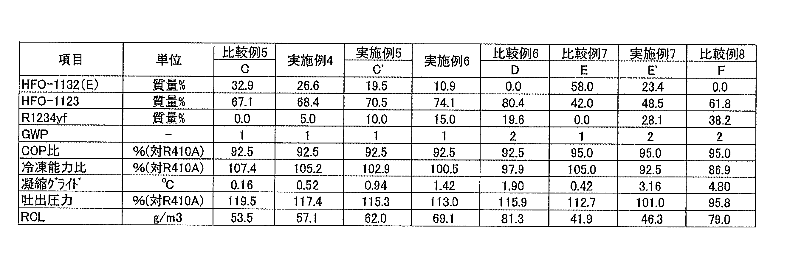
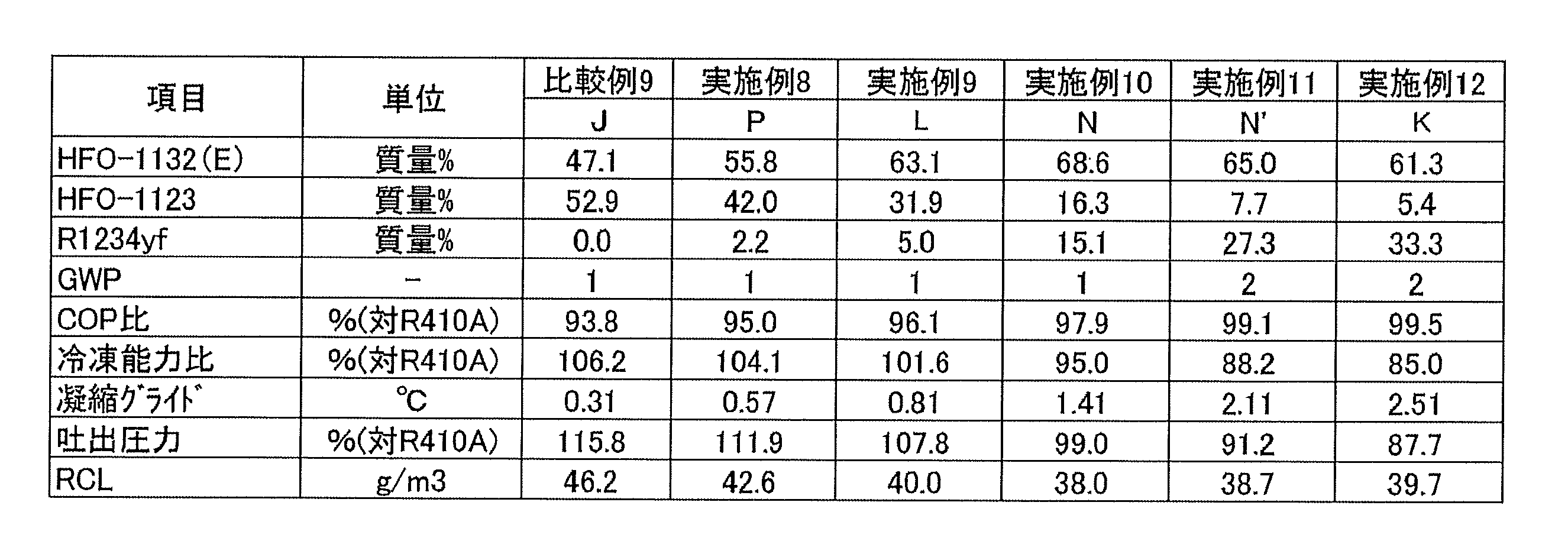
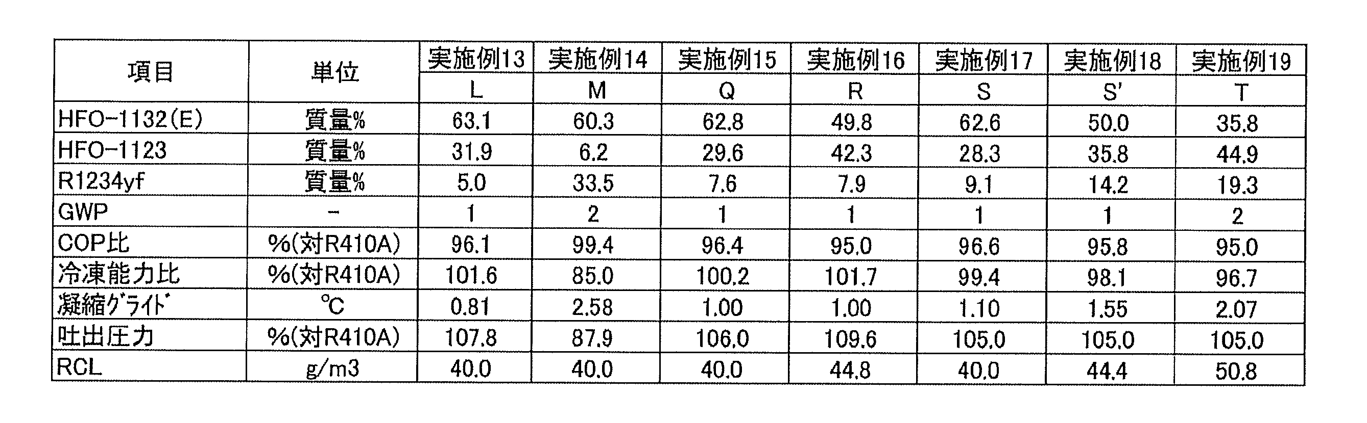


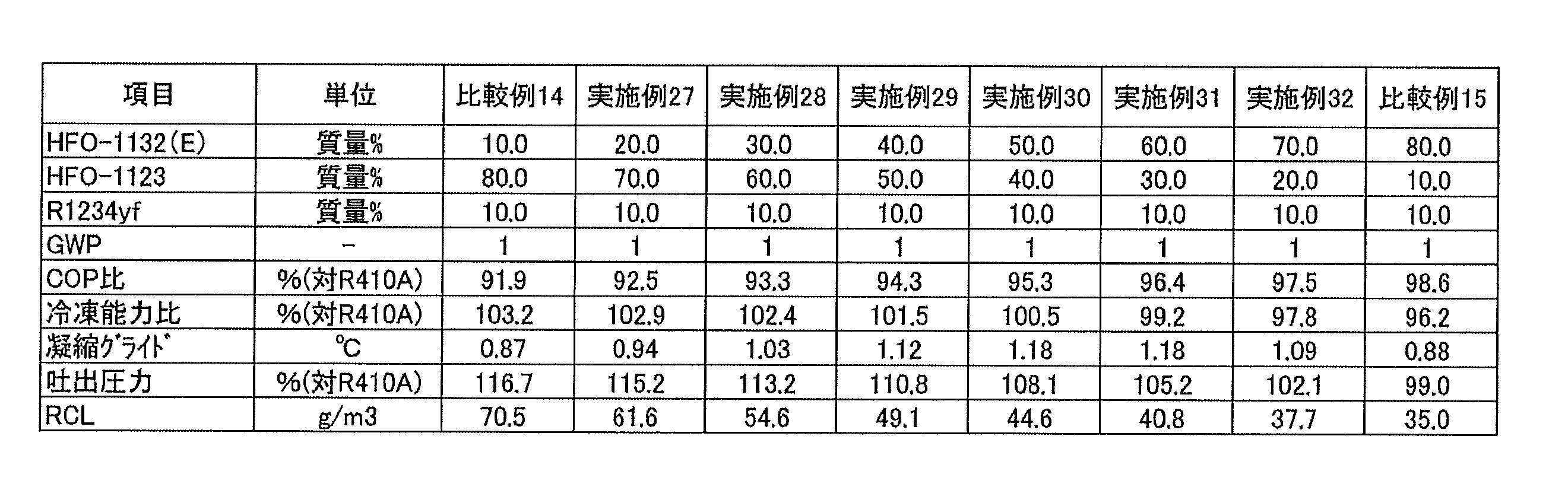


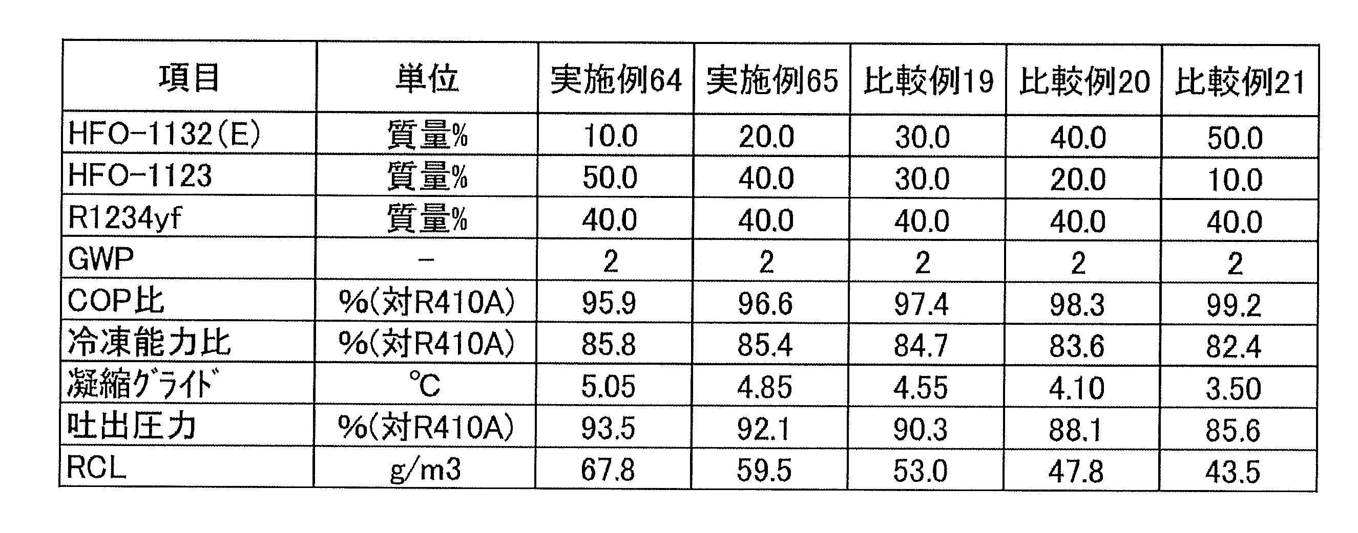
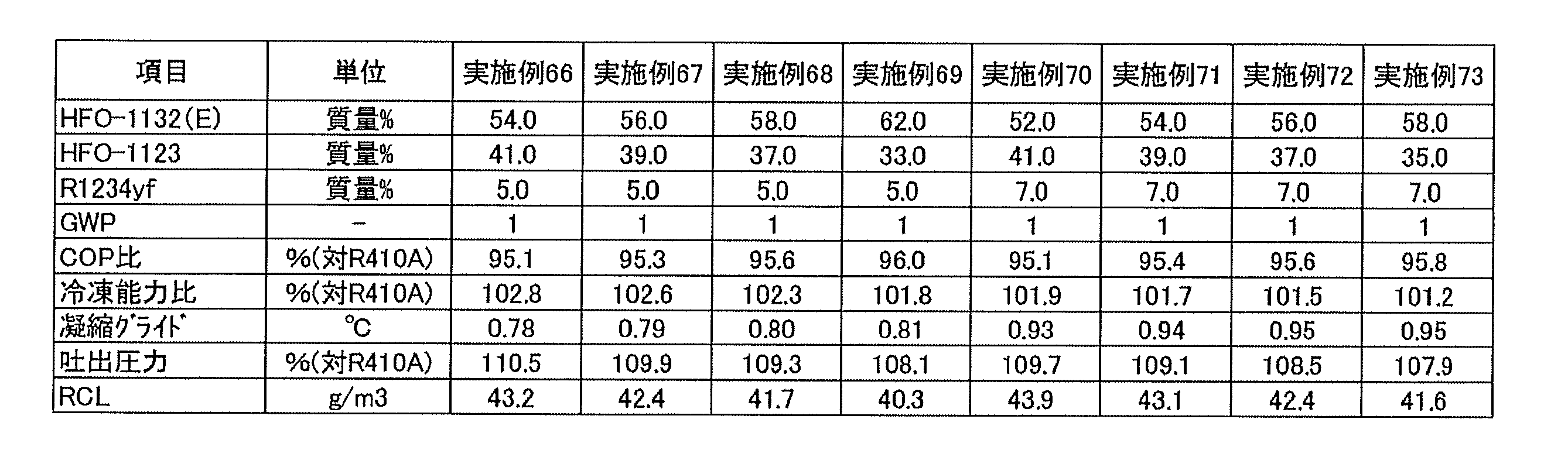


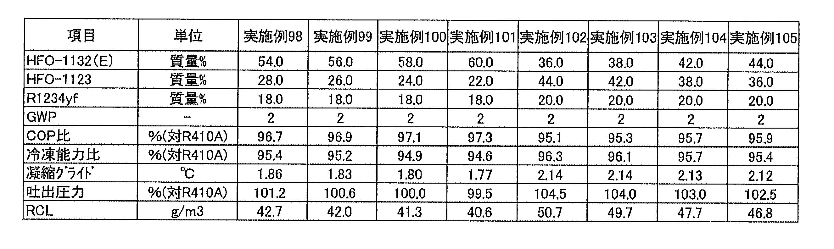
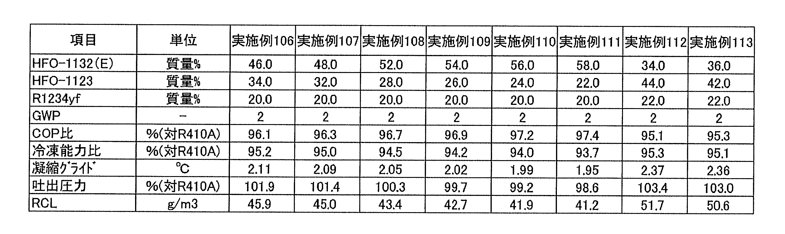
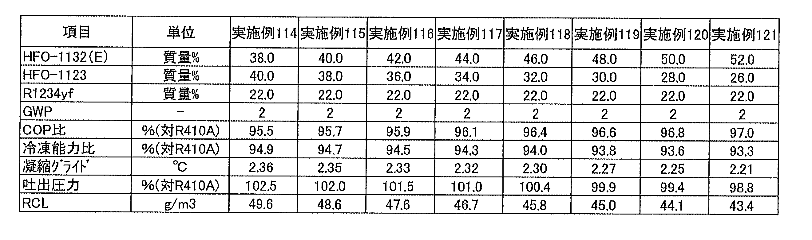

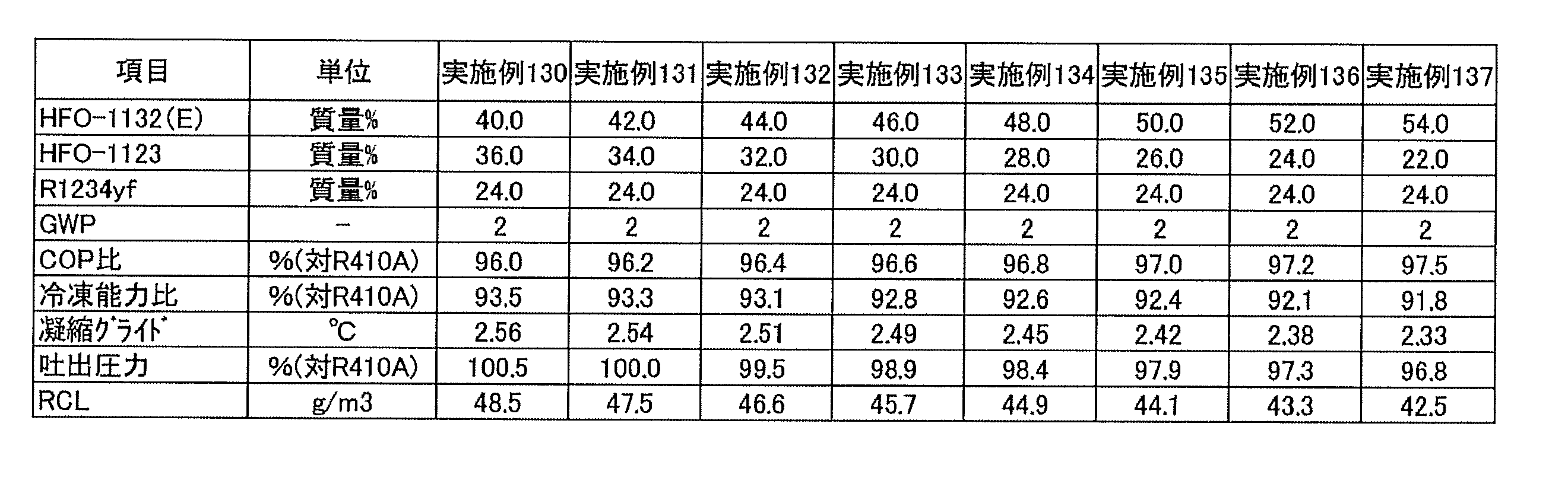


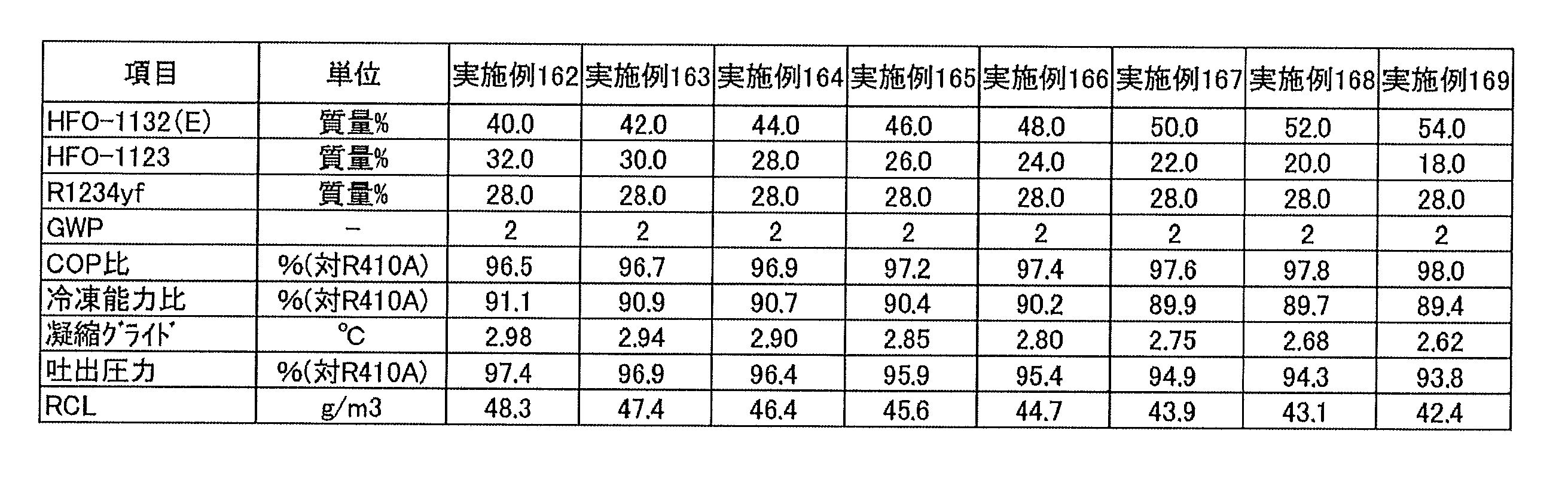
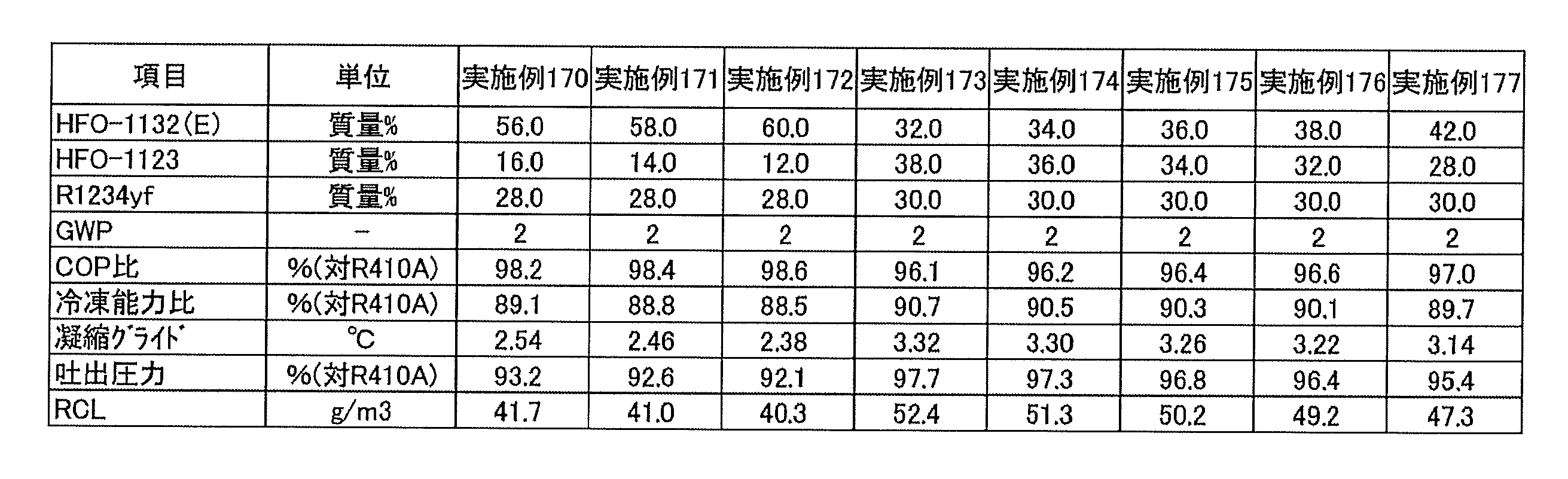


これらの結果から、HFO-1132(E)、HFO-1123及びR1234yfの、これらの総和を基準とする質量%をそれぞれx、y及びzとするとき、HFO-1132(E)、HFO-1123及びR1234yfの総和が100質量%となる3成分組成図において、座標(x,y,z)が、
点A(68.6, 0.0, 31.4)、
点A’(30.6, 30.0, 39.4)、
点B(0.0, 58.7, 41.3)、
点D(0.0, 80.4, 19.6)、
点C’(19.5, 70.5, 10.0)、
点C(32.9, 67.1, 0.0)及び
点O(100.0, 0.0, 0.0)
の7点をそれぞれ結ぶ線分AA’、A’B、BD、DC’、C’C、CO及びOAで囲まれる図形の範囲内又は前記線分上にあり(ただし、線分CO上の点は除く)、
前記線分AA’は、
座標(x, 0.0016x2-0.9473x+57.497, 0.0016x2-0.0527x+42.503)
で表わされ、
前記線分A’Bは、
座標(x, 0.0029x2-1.0268x+58.7, -0.0029x2+0.0268x+41.3)
で表わされ、
前記線分DC’は、
座標(x, 0.0082x2-0.6671x+80.4, -0.0082x2-0.3329x+19.6)
で表わされ、
前記線分C’Cは、
座標(x, 0.0067x2-0.6034x+79.729, -0.0067x2-0.3966x+20.271)
で表わされ、かつ
前記線分BD、CO及びOAが直線である場合に、R410Aを基準とする冷凍能力比が85%以上となり、かつR410Aを基準とするCOP比が92.5%以上となることが判る。 From these results, HFO-1132 (E), HFO-1123 and HFO-1123 and HFO-1123 and HFO-1123 and HFO-1123 and H1234b, respectively, are represented by x, y and z, respectively. In the three-component composition diagram in which the sum of R1234yf is 100% by mass, coordinates (x, y, z) are
Point A (68.6, 0.0, 31.4),
Point A '(30.6, 30.0, 39.4),
Point B (0.0, 58.7, 41.3),
Point D (0.0, 80.4, 19.6),
Point C '(19.5, 70.5, 10.0),
Point C (32.9, 67.1, 0.0) and point O (100.0, 0.0, 0.0)
Within the range of the figure enclosed by the line segment AA ', A' B, BD, DC ', C' C, CO and OA connecting the 7 points of Except),
The line segment AA ′ is
The coordinates (x, 0.0016x 2 -0.9473x + 57.497 , 0.0016x 2 -0.0527x + 42.503)
Represented by
The line segment A'B is
Coordinates (x, 0.0029x 2 -1.0268x + 58.7 , -0.0029x 2 + 0.0268x + 41.3)
Represented by
The line segment DC 'is
The coordinates (x, 0.0082x 2 -0.6671x + 80.4 , -0.0082x 2 -0.3329x + 19.6)
Represented by
The line segment C'C is
The coordinates (x, 0.0067x 2 -0.6034x + 79.729 , -0.0067x 2 -0.3966x + 20.271)
When the line segments BD, CO and OA are straight, the refrigeration capacity ratio based on R410A is 85% or more, and the COP ratio based on R410A is 92.5% or more Can be seen.
線分AA’上の点は、点A、実施例1、及び点A’の3点を結ぶ近似曲線を最小二乗法により求めることにより決定した。
The point on the line segment AA ′ was determined by finding an approximate curve connecting three points of the point A, the example 1, and the point A ′ by the least square method.
線分A’B上の点は、点A’、実施例3、及び点Bの3点を結ぶ近似曲線を最小二乗法により求めることにより決定した。
The point on the line segment A′B was determined by finding an approximate curve connecting the three points of the point A ′, the example 3 and the point B by the least square method.
線分DC’上の点は、点D、実施例6、及び点C’の3点を結ぶ近似曲線を最小二乗法により求めることにより決定した。
The point on the line segment DC ′ was determined by finding an approximate curve connecting the three points of the point D, the example 6, and the point C ′ by the least square method.
線分C’C上の点は、点C’、実施例4、及び点Cの3点を結ぶ近似曲線を最小二乗法により求めることにより決定した。
The point on line segment C'C was determined by calculating | requiring the approximated curve which ties three points of point C ', Example 4, and the point C by the least squares method.
また、同様に、座標(x,y,z)が、
点A(68.6, 0.0, 31.4)、
点A’(30.6, 30.0, 39.4)、
点B(0.0, 58.7, 41.3)、
点F(0.0, 61.8, 38.2)、
点T(35.8, 44.9, 19.3)、
点E(58.0, 42.0, 0.0)及び
点O(100.0, 0.0, 0.0)
の7点をそれぞれ結ぶ線分AA’、A’B、BF、FT、TE、EO及びOAで囲まれる図形の範囲内又は前記線分上にあり(ただし、線分EO上の点は除く)、
前記線分AA’は、
座標(x, 0.0016x2-0.9473x+57.497, -0.0016x2-0.0527x+42.503)
で表わされ、
前記線分A’Bは、
座標(x, 0.0029x2-1.0268x+58.7, -0.0029x2+0.0268x+41.3)
で表わされ、
前記線分FTは、
座標(x, 0.0078x2-0.7501x+61.8, -0.0078x2-0.2499x+38.2)
で表わされ、
前記線分TEは、
座標(x, 0.0067x2-0.7607x+63.525, -0.0067x2-0.2393x+36.475)
で表わされ、かつ
前記線分BF、FO及びOAが直線である場合に、R410Aを基準とする冷凍能力比が85%以上となり、かつR410Aを基準とするCOP比が95%以上となることが判る。 Similarly, the coordinates (x, y, z) are
Point A (68.6, 0.0, 31.4),
Point A '(30.6, 30.0, 39.4),
Point B (0.0, 58.7, 41.3),
Point F (0.0, 61.8, 38.2),
Point T (35.8, 44.9, 19.3),
Point E (58.0, 42.0, 0.0) and point O (100.0, 0.0, 0.0)
Within the range of the figure enclosed by the line segments AA ', A'B, BF, FT, TE, EO and OA connecting the 7 points of ,
The line segment AA ′ is
The coordinates (x, 0.0016x 2 -0.9473x + 57.497 , -0.0016x 2 -0.0527x + 42.503)
Represented by
The line segment A'B is
Coordinates (x, 0.0029x 2 -1.0268x + 58.7 , -0.0029x 2 + 0.0268x + 41.3)
Represented by
The line segment FT is
The coordinates (x, 0.0078x 2 -0.7501x + 61.8 , -0.0078x 2 -0.2499x + 38.2)
Represented by
The line segment TE is
The coordinates (x, 0.0067x 2 -0.7607x + 63.525 , -0.0067x 2 -0.2393x + 36.475)
When the line segments BF, FO and OA are straight, the refrigeration capacity ratio based on R410A is 85% or more, and the COP ratio based on R410A is 95% or more. Can be seen.
線分FT上の点は、点T、E’、Fの3点を結ぶ近似曲線を最小二乗法により求めることにより決定した。
The points on the line segment FT were determined by finding an approximate curve connecting the three points T, E 'and F by the least squares method.
線分TE上の点は、点E,R,Tの3点を結ぶ近似曲線を最小二乗法により求めることにより決定した。
The points on the line segment TE were determined by finding an approximate curve connecting the three points E, R and T by the least square method.
表1~34の結果から、HFO-1132(E)、HFO-1123及びR1234yfの混合冷媒においては、これらの総和が100質量%となる3成分組成図であって、点(0.0, 100.0, 0.0)及び点(0.0, 0.0, 100.0)を結ぶ線分を底辺とし、点(0.0, 100.0,0.0)を左側、点(0.0, 0.0, 100.0)を右側とする3成分組成図において、座標(x,y,z)が、
点L(63.1, 31.9, 5.0)及び
点M(60.3, 6.2, 33.5)
を結ぶ線分LMの上、又は当該線分の下側にある場合にRCLが40g/m3以上となることが明らかとなった。 From the results in Tables 1 to 34, in the mixed refrigerant of HFO-1132 (E), HFO-1123 and R1234yf, it is a three-component composition diagram in which the total of these is 100 mass%, and the points (0.0, 100.0, 0.0 And the point (0.0, 0.0, 100.0) on the left side and the point (0.0, 0.0, 100.0) on the right side in the three-component composition diagram with coordinates (x) , y, z),
Point L (63.1, 31.9, 5.0) and Point M (60.3, 6.2, 33.5)
It has become clear that RCL becomes 40 g / m 3 or more when it is above or below the line segment LM connecting the two.
また、表1~34の結果から、HFO-1132(E)、HFO-1123及びR1234yfの混合冷媒においては、これらの総和が100質量%となる3成分組成図であって、点(0.0, 100.0, 0.0)及び点(0.0, 0.0, 100.0)を結ぶ線分を底辺とし、点(0.0, 100.0, 0.0)を左側、点(0.0, 0.0, 100.0)を右側とする3成分組成図において、座標(x,y,z)が、
点Q(62.8, 29.6, 7.6) 及び
点R(49.8, 42.3, 7.9)
を結ぶ線分QRの上、又は当該線分の左側にある場合に温度グライドが1℃以下となることが明らかとなった。 Also, from the results of Tables 1 to 34, in the mixed refrigerant of HFO-1132 (E), HFO-1123 and R1234yf, it is a three-component composition diagram in which the total sum of these is 100 mass%, and the point (0.0, 100.0 , 0.0) and the point (0.0, 0.0, 100.0) are the base, and in the ternary composition diagram where the point (0.0, 100.0, 0.0) is on the left and the point (0.0, 0.0, 100.0) is on the right (X, y, z),
Point Q (62.8, 29.6, 7.6) and Point R (49.8, 42.3, 7.9)
It has become clear that the temperature glide is 1 ° C. or less when it is on the line segment QR connecting the two or to the left of the line segment.
また、表1~34の結果から、HFO-1132(E)、HFO-1123及びR1234yfの混合冷媒においては、これらの総和が100質量%となる3成分組成図であって、点(0.0, 100.0, 0.0)及び点(0.0, 0.0, 100.0)を結ぶ線分を底辺とし、点(0.0, 100.0, 0.0)を左側、点(0.0, 0.0, 100.0)を右側とする3成分組成図において、座標(x,y,z)が、
点S(62.6, 28.3, 9.1)及び
点T(35.8, 44.9, 19.3)
を結ぶ線分STの上、又は当該線分の右側にある場合にR410Aを基準とする吐出圧力比が105%以下となることが明らかとなった。 Also, from the results of Tables 1 to 34, in the mixed refrigerant of HFO-1132 (E), HFO-1123 and R1234yf, it is a three-component composition diagram in which the total sum of these is 100 mass%, and the point (0.0, 100.0 , 0.0) and the point (0.0, 0.0, 100.0) are the base, and in the ternary composition diagram where the point (0.0, 100.0, 0.0) is on the left and the point (0.0, 0.0, 100.0) is on the right (X, y, z),
Point S (62.6, 28.3, 9.1) and point T (35.8, 44.9, 19.3)
It has become clear that the discharge pressure ratio based on R410A is 105% or less when it is on the line segment ST connecting the two or on the right side of the line segment.
なお、これらの組成物において、R1234yfは燃焼性の低下や重合等の変質抑制に寄与しており、これを含むことが好ましい。
In these compositions, R1234yf contributes to the reduction of flammability and the suppression of deterioration such as polymerization, and it is preferable to include this.
さらに、これらの各混合冷媒について、混合組成をWCF濃度としてANSI/ASHRAE34-2013規格に従い燃焼速度を測定した。燃焼速度が10 cm/s以下となるものは「2Lクラス(微燃性)」であるとした。
Furthermore, for each of these mixed refrigerants, the burning rate was measured according to the ANSI / ASHRA 34-2013 standard, with the mixed composition as the WCF concentration. The one with a burning rate of 10 cm / s or less is considered as "2 L class (slight flammability)".
なお、燃焼速度試験は図1に示す装置を用いて、以下の通り行った。なお、図1において、901は試料セルを、902は高速カメラを、903はキセノンランプを、904はコリメートレンズを、905はコリメートレンズを、906はリングフィルターをそれぞれ示す。まず、使用した混合冷媒は99.5%またはそれ以上の純度とし、真空ゲージ上に空気の痕跡が見られなくなるまで凍結、ポンピング及び解凍のサイクルを繰り返すことにより脱気した。閉鎖法により燃焼速度を測定した。初期温度は周囲温度とした。点火は、試料セルの中心で電極間に電気的スパークを生じさせることにより行った。放電の持続時間は1.0~9.9msとし、点火エネルギーは典型的には約0.1~1.0Jであった。シュリーレン写真を使って炎の広がりを視覚化した。光を通す2つのアクリル窓を備えた円筒形容器(内径:155mm、長さ:198mm)を試料セルとして用い、光源としてはキセノンランプを用いた。炎のシュリーレン画像を高速デジタルビデオカメラで600fpsのフレーミング速度で記録し、PCに保存した。
In addition, the burning rate test was done as follows using the apparatus shown in FIG. In FIG. 1, 901 indicates a sample cell, 902 indicates a high-speed camera, 903 indicates a xenon lamp, 904 indicates a collimating lens, 905 indicates a collimating lens, and 906 indicates a ring filter. First, the mixed refrigerant used was 99.5% or more pure and degassed by repeated cycles of freezing, pumping and thawing until no traces of air were visible on the vacuum gauge. The burning rate was measured by the closure method. The initial temperature was ambient temperature. Ignition was performed by creating an electrical spark between the electrodes at the center of the sample cell. The duration of the discharge was 1.0 to 9.9 ms, and the ignition energy was typically about 0.1 to 1.0 J. The spread of the flame was visualized using Schlieren photographs. A cylindrical container (inner diameter: 155 mm, length: 198 mm) equipped with two acrylic windows for transmitting light was used as a sample cell, and a xenon lamp was used as a light source. Schlieren images of flames were recorded with a high speed digital video camera at a framing rate of 600 fps and stored on a PC.
また、WCFF濃度は、WCF濃度を初期濃度としてNIST Standard Reference Data Base Refleak Version 4.0により漏洩シミュレーションを行うことで求めた。
In addition, the WCFF concentration was determined by performing leakage simulation according to NIST Standard Reference Data Base Refleak Version 4.0 with the WCF concentration as the initial concentration.
結果を表35及び表36に示す。
The results are shown in Tables 35 and 36.
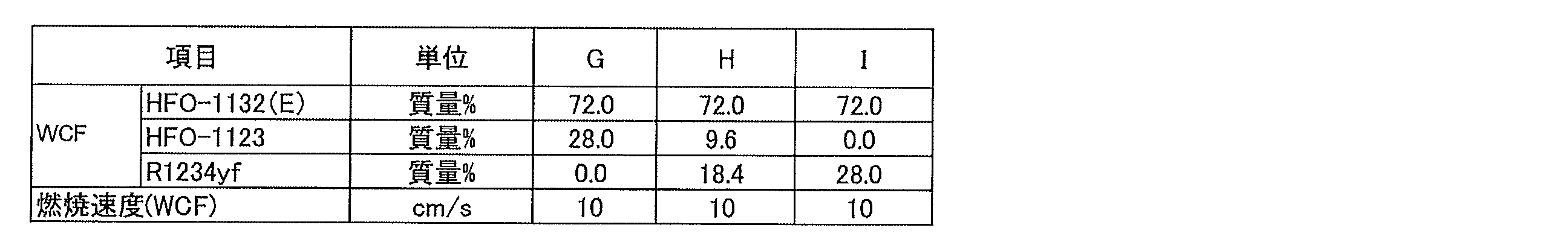

表35の結果から、HFO-1132(E)、HFO-1123及びR1234yfの混合冷媒においては、これらの総和を基準として、HFO-1132(E)を72.0質量%以下含む場合に、WCF微燃性と判断できることが明らかとなった。
From the results of Table 35, in the case of a mixed refrigerant of HFO-1132 (E), HFO-1123 and R1234yf, WCF slight flammability when containing 72.0 mass% or less of HFO-1132 (E) based on the total of these It became clear that it could be judged.
表36の結果から、HFO-1132(E)、HFO-1123及びR1234yfの混合冷媒においては、これらの総和が100質量%となる3成分組成図であって、点(0.0, 100.0,0.0)及び点(0.0, 0.0, 100.0)を結ぶ線分を底辺とする3成分組成図において、座標(x,y,z)が、
点J(47.1, 52.9, 0.0)、
点P(55.8, 42.0, 2.2)、
点L(63.1,31.9,5.0)
点N(68.6, 16.3, 15.1)
点N’(65.0,7.7,27.3)及び
点K(61.3, 5.4, 33.3)
の6点をそれぞれ結ぶ線分JP、PN及びNKの上、又は当該線分の下側にある場合に、WCF微燃、及びWCFF微燃性と判断できることが明らかとなった。 From the results of Table 36, in the case of a mixed refrigerant of HFO-1132 (E), HFO-1123 and R1234yf, it is a three-component composition diagram in which the total sum thereof becomes 100 mass%, and the points (0.0, 100.0, 0.0) and In a three-component composition diagram whose bottom is a line connecting points (0.0, 0.0, 100.0), coordinates (x, y, z) are
Point J (47.1, 52.9, 0.0),
Point P (55.8, 42.0, 2.2),
Point L (63.1, 31.9, 5.0)
Point N (68.6, 16.3, 15.1)
Point N '(65.0, 7.7, 27.3) and point K (61.3, 5.4, 33.3)
It has become clear that WCF slight combustion and WCFF slight combustion can be judged when they are above or below the line segments JP, PN and NK connecting the six points of.
ただし、前記線分PNは、
座標(x, -0.1135x2+12.112x-280.43, 0.1135x2-13.112x+380.43)
で表わされ、
前記線分NKは、
座標(x, 0.2421x2-29.955x+931.91, -0.2421x2+28.955x-831.91)
で表わされる。 However, the line segment PN is
Coordinates (x, -0.1135x 2 + 12.112x- 280.43, 0.1135x 2 -13.112x + 380.43)
Represented by
The line segment NK is
Coordinates (x, 0.2421x 2 -29.955x + 931.91, -0.2421x 2 + 28.955x-831.91)
It is represented by.
線分PN上の点は、点P、点L、点Nの3点を結ぶ近似曲線を最小二乗法により求めることにより決定した。
The point on the line segment PN was determined by finding an approximate curve connecting the three points P, L, and N by the least squares method.
線分NK上の点は、点N、点N’、点Kの3点を結ぶ近似曲線を最小二乗法により求めることにより決定した。
The point on the line segment NK was determined by finding an approximate curve connecting the three points of the point N, the point N 'and the point K by the least square method.
(5-2)冷媒B
本開示の冷媒Bは、
トランス-1,2-ジフルオロエチレン(HFO-1132(E))及びトリフルオロエチレン(HFO-1123)の合計を、該冷媒の全体に対して99.5質量%以上含み、かつ、該冷媒が、HFO-1132(E)を、該冷媒の全体に対して62.0質量%~72.0質量%又は45.1質量%~47.1質量%含む、混合冷媒であるか、または、
HFO-1132(E)及びHFO-1123の合計を、該冷媒の全体に対して99.5質量%以上含み、かつ該冷媒が、HFO-1132(E)を、該冷媒の全体に対して45.1質量%~47.1質量%含む、混合冷媒である。 (5-2) Refrigerant B
The refrigerant B of the present disclosure is
99.5 mass% or more of the total of trans-1,2-difluoroethylene (HFO-1132 (E)) and trifluoroethylene (HFO-1123) with respect to the whole of the refrigerant, and the refrigerant is HFO- Or a mixed refrigerant containing 62.0% by mass to 72.0% by mass or 45.1% by mass to 47.1% by mass of 1132 (E) based on the whole of the refrigerant, or
The total of HFO-1132 (E) and HFO-1123 is 99.5 mass% or more with respect to the whole of the refrigerant, and the refrigerant contains 40.1 mass% of HFO-1132 (E) with respect to the whole of the refrigerant It is a mixed refrigerant containing ̃47.1% by mass.
本開示の冷媒Bは、(1)R410Aと同等の成績係数を有すること、(2)R410Aと同等の冷凍能力を有すること、(3)GWPが十分に小さいこと、及び(4)ASHRAEの規格で微燃性(2Lクラス)であること、という、R410A代替冷媒として望ましい諸特性を有する。
The refrigerant B of the present disclosure has (1) a coefficient of performance equivalent to R410A, (2) refrigeration capacity equivalent to R410A, (3) sufficiently small GWP, and (4) ASHRAE standard. It has desirable characteristics as a R410A alternative refrigerant, that is, it is slightly flammable (2 L class).
本開示の冷媒Bは、HFO-1132(E)を72.0質量%以下含む混合冷媒であればWCF微燃となる。本開示の冷媒Bは、HFO-1132(E)を47.1%以下含む組成物であればWCF微燃及びWCFF微燃でASHRAE規格では微燃性冷媒である「2Lクラス」となり、取り扱いがさらに容易となる。
The refrigerant B of the present disclosure is a WCF slight-combustible if it is a mixed refrigerant containing 72.0% by mass or less of HFO-1132 (E). The refrigerant B of the present disclosure is a composition containing HFO-1132 (E) at 47.1% or less, and is a “2 L class” which is a slightly flammable refrigerant according to ASHRAE standards with WCF slight combustion and WCFF slight combustion, and handling is easier It becomes.
本開示の冷媒Bは、HFO-1132(E)を、62.0質量%以上含む場合、R410Aを基準とする成績係数比が95%以上でより優れたものとなり、かつHFO-1132(E)及び/又はHFO-1123の重合反応がより抑制され、安定性がより優れたものとなる。本開示の冷媒Bは、HFO-1132(E)を、45.1質量%以上含む場合、R410Aを基準とする成績係数比が93%以上でより優れたものとなり、かつHFO-1132(E)及び/又はHFO-1123の重合反応がより抑制され、安定性がより優れたものとなる。
When the refrigerant B of the present disclosure contains 62.0% by mass or more of HFO-1132 (E), the coefficient of performance coefficient based on R410A is more excellent at 95% or more, and HFO-1132 (E) and / or Or, the polymerization reaction of HFO-1123 is further suppressed, and the stability becomes more excellent. When the refrigerant B of the present disclosure contains 45.1% by mass or more of HFO-1132 (E), the coefficient of performance coefficient based on R410A is more excellent at 93% or more, and HFO-1132 (E) and / or Or, the polymerization reaction of HFO-1123 is further suppressed, and the stability becomes more excellent.
本開示の冷媒Bは、上記の特性や効果を損なわない範囲内で、HFO-1132(E)及びHFO-1123に加えて、さらに他の追加的な冷媒を含有していてもよい。この点で、本開示の冷媒Bが、HFO-1132(E)及びHFO-1123の合計を、冷媒全体に対して99.75質量%以上含むことがより好ましく、99.9質量%以上含むことがさらに好ましい。
The refrigerant B of the present disclosure may further contain other additional refrigerants in addition to HFO-1132 (E) and HFO-1123 as long as the above-described properties and effects are not impaired. In this respect, the refrigerant B of the present disclosure more preferably contains the total of HFO-1132 (E) and HFO-1123 at 99.75 mass% or more, further preferably 99.9 mass% or more with respect to the entire refrigerant.
追加的な冷媒としては、特に限定されず、幅広く選択できる。混合冷媒は、追加的な冷媒として、一種を単独で含んでいてもよいし、二種以上を含んでいてもよい。
The additional refrigerant is not particularly limited and can be widely selected. The mixed refrigerant may contain one kind alone as an additional refrigerant, or may contain two or more kinds.
(冷媒Bの実施例)
以下に、冷媒Bの実施例を挙げてさらに詳細に説明する。ただし、冷媒Bは、これらの実施例に限定されるものではない。 (Example of refrigerant B)
Below, the Example of the refrigerant | coolant B is mentioned and described in more detail. However, the refrigerant B is not limited to these examples.
以下に、冷媒Bの実施例を挙げてさらに詳細に説明する。ただし、冷媒Bは、これらの実施例に限定されるものではない。 (Example of refrigerant B)
Below, the Example of the refrigerant | coolant B is mentioned and described in more detail. However, the refrigerant B is not limited to these examples.
HFO-1132(E)及びHFO-1123を、これらの総和を基準として表37及び表38にそれぞれ示した質量%(mass%)で混合した混合冷媒を調製した。
A mixed refrigerant was prepared by mixing HFO-1132 (E) and HFO-1123 in mass% (mass%) shown in Table 37 and Table 38, respectively, based on the total of them.
R410A(R32=50%/R125=50%)の混合物を含有する組成物のGWPは、IPCC(Intergovernmental Panel on Climate Change)第4次報告書の値に基づいて評価した。HFO-1132(E)のGWPは記載がないが、HFO-1132a(GWP=1以下)、HFO-1123(GWP=0.3, 国際公開第2015/141678号に記載)から、そのGWPを1と想定した。R410A及びHFO-1132(E)とHFO-1123との混合物を含有する組成物の冷凍能力は、National Institute of Science and Technology(NIST) Reference Fluid Thermodynamic and Transport Properties Database(Refprop 9.0)を使い、下記条件で混合冷媒の冷凍サイクル理論計算を実施することにより求めた。
The GWP of a composition containing a mixture of R410A (R32 = 50% / R125 = 50%) was evaluated based on the value of the Intergovernmental Panel on Climate Change (IPCC) fourth report. Although GWP of HFO-1132 (E) is not described, HFO-1132a (GWP = 1 or less), HFO-1123 (GWP = 0.3, described in WO 2015/141678), the GWP is assumed to be 1. did. The refrigeration capacity of a composition containing a mixture of R410A and HFO-1132 (E) and HFO-1123 is as follows using the National Institute of Science and Technology (NIST) Reference Fluid Thermodynamic and Transport Properties Database (Refprop 9.0) It calculated | required by implementing the refrigeration cycle theoretical calculation of mixed refrigerant.
蒸発温度5℃
凝縮温度45℃
過熱温度5K
過冷却温度5K
圧縮機効率70%
また、各混合物の組成をWCFとし、ASHRAE34-2013規格に従って装置(Equipment)、貯蔵(Storage)、輸送(Shipping)、漏洩(Leak)及び再充填(Recharge)の条件でNIST Standard Reference Data Base Refleak Version 4.0により漏洩シミュレーションを行い、最も燃えやすい分画(fraction)をWCFFとした。 Evaporation temperature 5 ° C
Condensing temperature 45 ° C
Overheating temperature 5K
Subcooling temperature 5K
Compressor efficiency 70%
In addition, the composition of each mixture is WCF, and NIST Standard Reference Data Base Version under the condition of Equipment, Storage, Shipping, Leak, and Recharge according to ASHRAE 34-2013 standard. A leak simulation was performed according to 4.0, and the most flammable fraction was WCFF.
凝縮温度45℃
過熱温度5K
過冷却温度5K
圧縮機効率70%
また、各混合物の組成をWCFとし、ASHRAE34-2013規格に従って装置(Equipment)、貯蔵(Storage)、輸送(Shipping)、漏洩(Leak)及び再充填(Recharge)の条件でNIST Standard Reference Data Base Refleak Version 4.0により漏洩シミュレーションを行い、最も燃えやすい分画(fraction)をWCFFとした。 Evaporation temperature 5 ° C
Condensing temperature 45 ° C
Overheating temperature 5K
Subcooling temperature 5K
In addition, the composition of each mixture is WCF, and NIST Standard Reference Data Base Version under the condition of Equipment, Storage, Shipping, Leak, and Recharge according to ASHRAE 34-2013 standard. A leak simulation was performed according to 4.0, and the most flammable fraction was WCFF.
また、これらの結果をもとに算出したGWP、COP及び冷凍能力を表1、表2に示す。なお、比COP及び比冷凍能力については、R410Aに対する割合を示す。
Further, GWP, COP and refrigeration capacity calculated based on these results are shown in Tables 1 and 2. The ratio COP and the specific refrigeration capacity are shown relative to R410A.
成績係数(COP)は、次式により求めた。
The coefficient of performance (COP) was determined by the following equation.
COP =(冷凍能力又は暖房能力)/消費電力量
また、燃焼性はANSI/ASHRAE34-2013規格に従い燃焼速度を測定した。燃焼速度がWCF及びWCFFともに10 cm/s以下となるものは「2Lクラス(微燃性)」であるとした。 COP = (refrigeration capacity or heating capacity) / power consumption Also, the flammability was measured the burning rate according to the ANSI / ASHRAE 34-2013 standard. If the burning rate is 10 cm / s or less for both WCF and WCFF, it is considered as "2 L class (slight flammability)".
また、燃焼性はANSI/ASHRAE34-2013規格に従い燃焼速度を測定した。燃焼速度がWCF及びWCFFともに10 cm/s以下となるものは「2Lクラス(微燃性)」であるとした。 COP = (refrigeration capacity or heating capacity) / power consumption Also, the flammability was measured the burning rate according to the ANSI / ASHRAE 34-2013 standard. If the burning rate is 10 cm / s or less for both WCF and WCFF, it is considered as "2 L class (slight flammability)".
燃焼速度試験は図1に示す装置を用いて、以下の通り行った。まず、使用した混合冷媒は99.5%またはそれ以上の純度とし、真空ゲージ上に空気の痕跡が見られなくなるまで凍結、ポンピング及び解凍のサイクルを繰り返すことにより脱気した。閉鎖法により燃焼速度を測定した。初期温度は周囲温度とした。点火は、試料セルの中心で電極間に電気的スパークを生じさせることにより行った。放電の持続時間は1.0~9.9msとし、点火エネルギーは典型的には約0.1~1.0Jであった。シュリーレン写真を使って炎の広がりを視覚化した。光を通す2つのアクリル窓を備えた円筒形容器(内径:155mm、長さ:198mm)を試料セルとして用い、光源としてはキセノンランプを用いた。炎のシュリーレン画像を高速デジタルビデオカメラで600fpsのフレーミング速度で記録し、PCに保存した。
The burning rate test was conducted as follows using the apparatus shown in FIG. First, the mixed refrigerant used was 99.5% or more pure and degassed by repeated cycles of freezing, pumping and thawing until no traces of air were visible on the vacuum gauge. The burning rate was measured by the closure method. The initial temperature was ambient temperature. Ignition was performed by creating an electrical spark between the electrodes at the center of the sample cell. The duration of the discharge was 1.0 to 9.9 ms, and the ignition energy was typically about 0.1 to 1.0 J. The spread of the flame was visualized using Schlieren photographs. A cylindrical container (inner diameter: 155 mm, length: 198 mm) equipped with two acrylic windows for transmitting light was used as a sample cell, and a xenon lamp was used as a light source. Schlieren images of flames were recorded with a high speed digital video camera at a framing rate of 600 fps and stored on a PC.
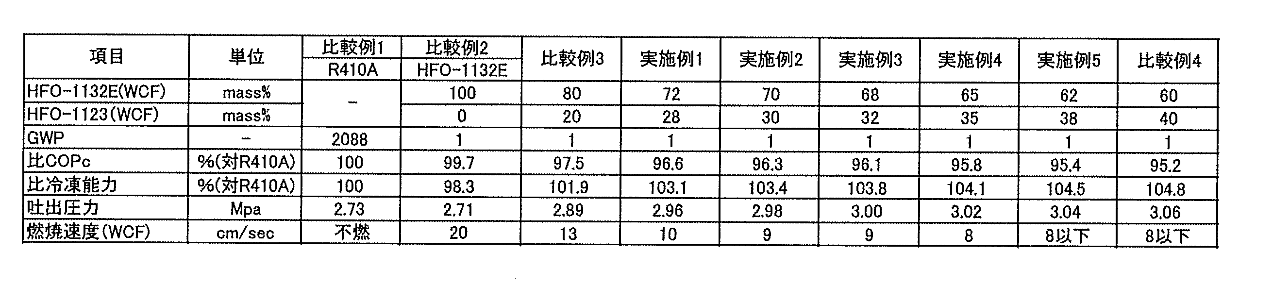
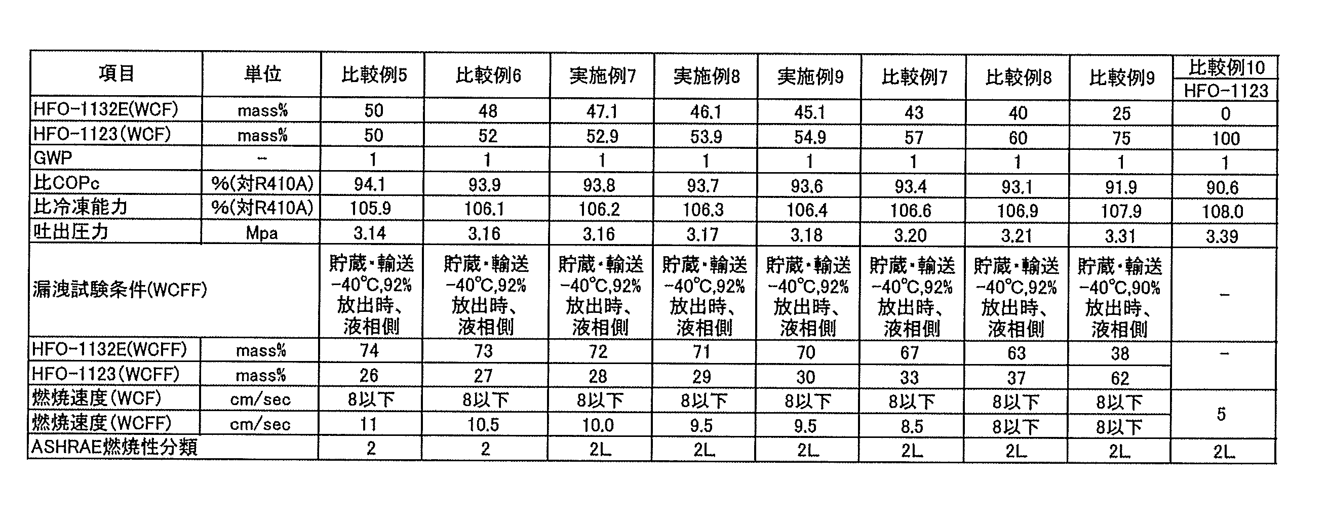
組成物が、HFO-1132(E)を、該組成物の全体に対して62.0質量%~72.0質量%含む場合に、GWP=1という低いGWPを持ちつつも安定で、かつ、WCF微燃を確保し、更に驚くべきことにR410Aと同等の性能を確保することができる。また、組成物が、HFO-1132(E)を、該組成物の全体に対して45.1質量%~47.1質量%含む場合に、GWP=1という低いGWPを持ちつつも安定で、かつ、WCFF微燃を確保し、更に驚くべきことにR410Aと同等の性能を確保することができる。
When the composition contains HFO-1132 (E) in an amount of 62.0% by mass to 72.0% by mass with respect to the entire composition, it is stable while having a low GWP of GWP = 1, and WCF fine combustion In addition, it is possible to secure the same performance as R410A. In addition, when the composition contains HFO-1132 (E) in an amount of 45.1% by mass to 47.1% by mass with respect to the entire composition, it is stable while having a low GWP of GWP = 1 and WCFF fine. It is possible to secure the combustion and, more surprisingly, to ensure the performance equivalent to that of the R410A.
(5-3)冷媒C
本開示の冷媒Cは、トランス-1,2-ジフルオロエチレン(HFO-1132(E))、トリフルオロエチレン(HFO-1123)及び2,3,3,3-テトラフルオロ-1-プロペン(R1234yf)、並びにジフルオロメタン(R32)を含む組成物であって、さらに以下の要件を満たす。本開示の冷媒Cは、R410Aと同等の冷凍能力及び成績係数を有し、かつGWPが十分に小さい、という、R410A代替冷媒として望ましい諸特性を有する。 (5-3) Refrigerant C
Refrigerant C of the present disclosure includes trans-1,2-difluoroethylene (HFO-1132 (E)), trifluoroethylene (HFO-1123) and 2,3,3,3-tetrafluoro-1-propene (R1234yf). And difluoromethane (R32), which further satisfy the following requirements. The refrigerant C of the present disclosure has desirable characteristics as an R410A alternative refrigerant, having a refrigeration capacity and a coefficient of performance equivalent to that of R410A, and having a sufficiently small GWP.
要件:
本開示の冷媒Cは、HFO-1132(E)、HFO-1123及びR1234yf、並びにR32の、これらの総和を基準とする質量%をそれぞれx、y及びz、並びにaとするとき、HFO-1132(E)、HFO-1123及びR1234yfの総和が(100-a)質量%となる3成分組成図において、座標(x,y,z)が、
0<a≦11.1のとき、
点G(0.026a2-1.7478a+72.0, -0.026a2+0.7478a+28.0, 0.0)、
点I(0.026a2-1.7478a+72.0, 0.0, -0.026a2+0.7478a+28.0)、
点A(0.0134a2-1.9681a+68.6, 0.0, -0.0134a2+0.9681a+31.4)、
点B(0.0, 0.0144a2-1.6377a+58.7, -0.0144a2+0.6377a+41.3)、
点D’(0.0, 0.0224a2+0.968a+75.4, -0.0224a2-1.968a+24.6)及び
点C(-0.2304a2-0.4062a+32.9, 0.2304a2-0.5938a+67.1, 0.0)
の6点をそれぞれ結ぶ直線GI、IA、AB、BD’、D’C及びCGで囲まれる図形の範囲内又は前記直線GI、AB及びD’C上にあり(ただし、点G、点I、点A、点B、点D’及び点Cは除く)、
11.1<a≦18.2のとき、
点G(0.02a2-1.6013a+71.105, -0.02a2+0.6013a+28.895, 0.0)、
点I(0.02a2-1.6013a+71.105, 0.0, -0.02a2+0.6013a+28.895)、
点A(0.0112a2-1.9337a+68.484, 0.0, -0.0112a2+0.9337a+31.516)、
点B(0.0, 0.0075a2-1.5156a+58.199, -0.0075a2+0.5156a+41.801)及び
点W(0.0, 100.0-a, 0.0)
の5点をそれぞれ結ぶ直線GI、IA、AB、BW及びWGで囲まれる図形の範囲内又は前記直線GI及びAB上にあり(ただし、点G、点I、点A、点B及び点Wは除く)、
18.2<a≦26.7のとき、
点G(0.0135a2-1.4068a+69.727, -0.0135a2+0.4068a+30.273, 0.0)、
点I(0.0135a2-1.4068a+69.727, 0.0, -0.0135a2+0.4068a+30.273)、
点A(0.0107a2-1.9142a+68.305, 0.0, -0.0107a2+0.9142a+31.695)、
点B(0.0, 0.009a2-1.6045a+59.318, -0.009a2+0.6045a+40.682)及び
点W(0.0, 100.0-a, 0.0)
の5点をそれぞれ結ぶ直線GI、IA、AB、BW及びWGで囲まれる図形の範囲内又は前記直線GI及びAB上にあり(ただし、点G、点I、点A、点B及び点Wは除く)、
26.7<a≦36.7のとき、
点G(0.0111a2-1.3152a+68.986, -0.0111a2+0.3152a+31.014, 0.0)、
点I(0.0111a2-1.3152a+68.986, 0.0, -0.0111a2+0.3152a+31.014)、
点A(0.0103a2-1.9225a+68.793, 0.0, -0.0103a2+0.9225a+31.207)、
点B(0.0, 0.0046a2-1.41a+57.286, -0.0046a2+0.41a+42.714)及び
点W(0.0, 100.0-a, 0.0)
の5点をそれぞれ結ぶ直線GI、IA、AB、BW及びWGで囲まれる図形の範囲内又は前記直線GI及びAB上にあり(ただし、点G、点I、点A、点B及び点Wは除く)、及び
36.7<a≦46.7のとき、
点G(0.0061a2-0.9918a+63.902, -0.0061a2-0.0082a+36.098, 0.0)、
点I(0.0061a2-0.9918a+63.902, 0.0, -0.0061a2+0.0082a+36.098)、
点A(0.0085a2-1.8102a+67.1, 0.0, -0.0085a2+0.8102a+32.9)、
点B(0.0, 0.0012a2-1.1659a+52.95, -0.0012a2+0.1659a+47.05)及び
点W(0.0, 100.0-a, 0.0)
の5点をそれぞれ結ぶ直線GI、IA、AB、BW及びWGで囲まれる図形の範囲内又は前記直線GI及びAB上にある(ただし、点G、点I、点A、点B及び点Wは除く)ものが含まれる。本開示の冷媒は、上記要件が満たされる場合、R410Aを基準とする冷凍能力比が85%以上となり、かつR410Aを基準とするCOP比が92.5%以上となり、さらにWCF微燃性となる。 Requirement:
The refrigerant C of the present disclosure is HFO-1132, where the mass% of HFO-1132 (E), HFO-1123 and R1234yf, and R32 based on the total of these is x, y and z, and a, respectively. In the three-component composition diagram in which the sum of (E), HFO-1123 and R1234yf is (100−a) mass%, coordinates (x, y, z) are
When 0 <a ≦ 11.1
Point G (0.026a 2 -1.7478a + 72.0, -0.026a 2 + 0.7478a + 28.0, 0.0),
Point I (0.026a 2 -1.7478a + 72.0, 0.0, -0.026a 2 + 0.7478a + 28.0),
Point A (0.0134a 2 -1.9681a + 68.6, 0.0, -0.0134a 2 + 0.9681a + 31.4),
Point B (0.0, 0.0144a 2 -1.6377a + 58.7,-0.0144a 2 + 0.6377a + 41.3),
Point D '(0.0, 0.0224a 2 + 0.968a + 75.4, -0.0224a 2 -1.968a + 24.6) and point C (-0.2304a 2 -0.4062a + 32.9, 0.2304a 2 -0.5938a + 67.1, 0.0)
Within the range of the figure enclosed by straight lines GI, IA, AB, BD ′, D′ C and CG respectively connecting the six points of the above, or on the straight lines GI, AB and D′ C Except point A, point B, point D 'and point C),
When 11.1 <a ≦ 18.2
Point G (0.02a 2 -1.6013a + 71.105, -0.02a 2 + 0.6013a + 28.895, 0.0),
Point I (0.02a 2 -1.6013a + 71.105, 0.0, -0.02a 2 + 0.6013a + 28.895),
Point A (0.0112a 2 -1.9337a + 68.484, 0.0, -0.0112a 2 + 0.9337a + 31.516),
Point B (0.0, 0.0075a 2 -1.5156a + 58.199, -0.0075a 2 + 0.5156a + 41.801) and point W (0.0, 100.0-a, 0.0)
In the range of the figure enclosed by straight lines GI, IA, AB, BW and WG respectively connecting the five points of the above, or on the straight lines GI and AB (however, points G, I, except),
When 18.2 <a ≦ 26.7
Point G (0.0135a 2 -1. 4068a + 69. 727, -0.0135a 2 + 0.4068a + 30. 273, 0.0),
Point I (0.0135a 2 -1. 4068a + 69. 727, 0.0, -0.0135a 2 + 0.4068a + 30. 273),
Point A (0.0107a 2 -1.9142a + 68.305, 0.0, -0.0107a 2 + 0.9142a + 31.695),
Point B (0.0, 0.009a 2 -1.6045a + 59.318, -0.009a 2 + 0.6045a + 40.682) and the point W (0.0, 100.0-a, 0.0)
In the range of the figure enclosed by straight lines GI, IA, AB, BW and WG respectively connecting the five points of the above, or on the straight lines GI and AB (however, points G, I, except),
When 26.7 <a ≦ 36.7
Point G (0.0111a 2 -1.3152a + 68.986,-0.0111a 2 + 0.3152a + 31.014, 0.0),
Point I (0.0111a 2 -1.3152a + 68.986, 0.0,-0.0111a 2 + 0.3152a + 31.014),
Point A (0.0103a 2 -1.9225a + 68.793, 0.0, -0.0103a 2 + 0.9225a + 31.207),
Point B (0.0, 0.0046a 2 -1.41a + 57.286, -0.0046a 2 + 0.41a + 42.714) and the point W (0.0, 100.0-a, 0.0)
In the range of the figure enclosed by straight lines GI, IA, AB, BW and WG respectively connecting the five points of the above, or on the straight lines GI and AB (however, points G, I, And 36.7 <a ≦ 46.7,
Point G (0.0061a 2 -0.9918a + 63.902, -0.0061a 2 -0.0082a + 36.098, 0.0),
Point I (0.0061a 2 -0.9918a + 63.902, 0.0, -0.0061a 2 + 0.0082a + 36.098),
Point A (0.0085a 2 -1.8102a + 67.1, 0.0, -0.0085a 2 + 0.8102a + 32.9),
Point B (0.0, 0.0012a 2 -1.1659a + 52.95, -0.0012a 2 + 0.1659a + 47.05) and the point W (0.0, 100.0-a, 0.0)
Within the range of the figure enclosed by straight lines GI, IA, AB, BW and WG respectively connecting the five points of the above (wherein point G, point I, point A, point B and point W are Excluded). When the above requirement is satisfied, the refrigerant of the present disclosure has a refrigeration capacity ratio of 85% or more based on R410A, a COP ratio based on R410A of 92.5% or more, and WCF slight flame retardancy.
本開示の冷媒Cは、HFO-1132(E)、HFO-1123及びR1234yfの、これらの総和を基準とする質量%をそれぞれx、y及びzとするとき、HFO-1132(E)、HFO-1123及びR1234yfの総和が(100-a)質量%となる3成分組成図において、座標(x,y,z)が、
0<a≦11.1のとき、
点J(0.0049a2-0.9645a+47.1, -0.0049a2-0.0355a+52.9, 0.0)、
点K’(0.0514a2-2.4353a+61.7, -0.0323a2+0.4122a+5.9, -0.0191a2+1.0231a+32.4)、
点B(0.0, 0.0144a2-1.6377a+58.7, -0.0144a2+0.6377a+41.3)、
点D’(0.0, 0.0224a2+0.968a+75.4, -0.0224a2-1.968a+24.6)及び
点C(-0.2304a2-0.4062a+32.9, 0.2304a2-0.5938a+67.1, 0.0)
の5点をそれぞれ結ぶ直線JK’、K’B、BD’、D’C及びCJで囲まれる図形の範囲内又は前記直線JK’、K’B及びD’C上にあり(ただし、点J、点B、点D’及び点Cは除く)、
11.1<a≦18.2のとき、
点J(0.0243a2-1.4161a+49.725, -0.0243a2+0.4161a+50.275, 0.0)、
点K’(0.0341a2-2.1977a+61.187, -0.0236a2+0.34a+5.636, -0.0105a2+0.8577a+33.177)、
点B(0.0, 0.0075a2-1.5156a+58.199, -0.0075a2+0.5156a+41.801)及び
点W(0.0, 100.0-a, 0.0)
の4点をそれぞれ結ぶ直線JK’、K’B、BW及びWJで囲まれる図形の範囲内又は前記直線JK’及びK’B上にあり(ただし、点J、点B及び点Wは除く)、
18.2<a≦26.7のとき、
点J(0.0246a2-1.4476a+50.184, -0.0246a2+0.4476a+49.816, 0.0)、
点K’(0.0196a2-1.7863a+58.515, -0.0079a2-0.1136a+8.702, -0.0117a2+0.8999a+32.783)、
点B(0.0, 0.009a2-1.6045a+59.318, -0.009a2+0.6045a+40.682)及び
点W(0.0, 100.0-a, 0.0)
の4点をそれぞれ結ぶ直線JK’、K’B、BW及びWJで囲まれる図形の範囲内又は前記直線JK’及びK’B上にあり(ただし、点J、点B及び点Wは除く)、
26.7<a≦36.7のとき、
点J(0.0183a2-1.1399a+46.493, -0.0183a2+0.1399a+53.507, 0.0)、
点K’(-0.0051a2+0.0929a+25.95, 0.0, 0.0051a2-1.0929a+74.05)、
点A(0.0103a2-1.9225a+68.793, 0.0, -0.0103a2+0.9225a+31.207)、
点B(0.0, 0.0046a2-1.41a+57.286, -0.0046a2+0.41a+42.714)及び
点W(0.0, 100.0-a, 0.0)
の5点をそれぞれ結ぶ直線JK’、K’A、AB、BW及びWJで囲まれる図形の範囲内又は前記直線JK’、K'A及びAB上にあり(ただし、点J、点B及び点Wは除く)、及び
36.7<a≦46.7のとき、
点J(-0.0134a2+1.0956a+7.13, 0.0134a2-2.0956a+92.87, 0.0)、
点K’(-1.892a+29.443, 0.0, 0.892a+70.557)、
点A(0.0085a2-1.8102a+67.1, 0.0, -0.0085a2+0.8102a+32.9)、
点B(0.0, 0.0012a2-1.1659a+52.95, -0.0012a2+0.1659a+47.05)及び
点W(0.0, 100.0-a, 0.0)
の5点をそれぞれ結ぶ直線JK’、K’A、AB、BW及びWJで囲まれる図形の範囲内又は前記直線JK’、K'A及びAB上にある(ただし、点J、点B及び点Wは除く)ものが含まれる。本開示の冷媒は、上記要件が満たされる場合、R410Aを基準とする冷凍能力比が85%以上となり、かつR410Aを基準とするCOP比が92.5%以上となるだけでなく、さらにWCF微燃及びWCFF微燃でASHRAE規格では微燃性冷媒である「2Lクラス」を示す。 The refrigerant C of the present disclosure is HFO-1132 (E), HFO- when the mass% of HFO-1132 (E), HFO-1123 and R1234yf based on the total of these is respectively x, y and z. In a three-component composition diagram in which the sum of 1123 and R1234yf is (100−a) mass%, coordinates (x, y, z) are
When 0 <a ≦ 11.1
Point J (0.0049a 2 -0.9645a + 47.1, -0.0049a 2 -0.0355a + 52.9, 0.0),
Point K '(0.0514a 2 -2.4353a + 61.7 , -0.0323a 2 + 0.4122a + 5.9, -0.0191a 2 + 1.0231a + 32.4),
Point B (0.0, 0.0144a 2 -1.6377a + 58.7,-0.0144a 2 + 0.6377a + 41.3),
Point D '(0.0, 0.0224a 2 + 0.968a + 75.4, -0.0224a 2 -1.968a + 24.6) and point C (-0.2304a 2 -0.4062a + 32.9, 0.2304a 2 -0.5938a + 67.1, 0.0)
Within the range of the figure enclosed by the straight lines JK ′, K′B, BD ′, D′ C and CJ respectively connecting the five points of the above, or on the straight lines JK ′, K′B and D′ C (however, point J , Point B, point D 'and point C),
When 11.1 <a ≦ 18.2
Point J (0.0243a 2 -1.4161a + 49.725, -0.0243a 2 + 0.4161a + 50.275, 0.0),
Point K '(0.0341a 2 -2.1977a + 61.187 , -0.0236a 2 + 0.34a + 5.636, -0.0105a 2 + 0.8577a + 33.177),
Point B (0.0, 0.0075a 2 -1.5156a + 58.199, -0.0075a 2 + 0.5156a + 41.801) and point W (0.0, 100.0-a, 0.0)
In the range of the figure bounded by the straight lines JK ', K'B, BW and WJ connecting the four points of the above, or on the straight lines JK' and K'B (except for the points J, B and W) ,
When 18.2 <a ≦ 26.7
Point J (0.0246a 2 -1.4476a + 50.184, -0.0246a 2 + 0.4476a + 49.816, 0.0),
Point K '(0.0196a 2 -1.7863a + 58.515 , -0.0079a 2 -0.1136a + 8.702, -0.0117a 2 + 0.8999a + 32.783),
Point B (0.0, 0.009a 2 -1.6045a + 59.318, -0.009a 2 + 0.6045a + 40.682) and the point W (0.0, 100.0-a, 0.0)
In the range of the figure bounded by the straight lines JK ', K'B, BW and WJ connecting the four points of the above, or on the straight lines JK' and K'B (except for the points J, B and W) ,
When 26.7 <a ≦ 36.7
Point J (0.0183a 2 -1.1399a + 46.493, -0.0183a 2 + 0.1399a + 53.507, 0.0),
Point K ′ (−0.0051a 2 + 0.0929a +25.95, 0.0, 0.0051a 2 -1.0929a + 74.05),
Point A (0.0103a 2 -1.9225a + 68.793, 0.0, -0.0103a 2 + 0.9225a + 31.207),
Point B (0.0, 0.0046a 2 -1.41a + 57.286, -0.0046a 2 + 0.41a + 42.714) and the point W (0.0, 100.0-a, 0.0)
Within the range of the figure enclosed by the straight lines JK ′, K′A, AB, BW and WJ respectively connecting the five points of the above, or on the straight lines JK ′, K′A and AB (however, point J, point B and points W is excluded), and when 36.7 <a ≦ 46.7,
Point J (-0.0134a 2 + 1.0956a +7.13, 0.0134a 2 -2.0956a + 92.87, 0.0),
Point K '(-1.892a + 29.443, 0.0, 0.892a + 70.557),
Point A (0.0085a 2 -1.8102a + 67.1, 0.0, -0.0085a 2 + 0.8102a + 32.9),
Point B (0.0, 0.0012a 2 -1.1659a + 52.95, -0.0012a 2 + 0.1659a + 47.05) and the point W (0.0, 100.0-a, 0.0)
Within the range of the figure bounded by the straight lines JK ′, K′A, AB, BW and WJ respectively connecting the five points of the above, or on the straight lines JK ′, K′A and AB W) is included. The refrigerant of the present disclosure not only achieves a refrigeration capacity ratio of 85% or more based on R410A and a COP ratio of 92.5% or more based on R410A when the above requirements are satisfied, and further, WCF slight combustion and WCFF slight burn and ASHRAE standards indicate "2L class", a slightly burnt refrigerant.
本開示の冷媒Cは、HFO-1132(E)、HFO-1123及びR1234yfに加えて、さらにR32を含む場合、HFO-1132(E)、HFO-1123及びR1234yf並びにR32の、これらの総和を基準とする質量%をそれぞれx、y及びz並びにaとするとき、HFO-1132(E)、HFO-1123及びR1234yfの総和が(100-a)質量%となる3成分組成図において、座標(x,y,z)が、
0<a≦10.0のとき、
点a(0.02a2-2.46a+93.4, 0, -0.02a2+2.46a+6.6)、
点b’(-0.008a2-1.38a+56, 0.018a2-0.53a+26.3, -0.01a2+1.91a+17.7)、
点c(-0.016a2+1.02a+77.6, 0.016a2-1.02a+22.4, 0)及び
点o(100.0-a, 0.0, 0.0)
の4点をそれぞれ結ぶ直線で囲まれる図形の範囲内又は前記直線oa、ab’及びb’c上にあり(ただし、点o及び点cは除く)、
10.0<a≦16.5のとき、
点a(0.0244a2-2.5695a+94.056, 0, -0.0244a2+2.5695a+5.944)、
点b’(0.1161a2-1.9959a+59.749, 0.014a2-0.3399a+24.8, -0.1301a2+2.3358a+15.451)、
点c(-0.0161a2+1.02a+77.6, 0.0161a2-1.02a+22.4, 0)及び
点o(100.0-a, 0.0, 0.0)
の4点をそれぞれ結ぶ直線で囲まれる図形の範囲内又は前記直線oa、ab’及びb’c上にあり(ただし、点o及び点cは除く)、又は
16.5<a≦21.8のとき、
点a(0.0161a2-2.3535a+92.742, 0, -0.0161a2+2.3535a+7.258)、
点b’(-0.0435a2-0.0435a+50.406, -0.0304a2+1.8991a-0.0661, 0.0739a2-1.8556a+49.6601)、
点c(-0.0161a2+0.9959a+77.851, 0.0161a2-0.9959a+22.149, 0)及び
点o(100.0-a, 0.0, 0.0)
の4点をそれぞれ結ぶ直線で囲まれる図形の範囲内又は前記直線oa、ab’及びb’c上にあるものとすることができる(ただし、点o及び点cは除く)。なお、点b’は、前記3成分組成図において、R410Aを基準とする冷凍能力比が95%となり、かつR410Aを基準とするCOP比が95%となる点を点bとすると、R410Aを基準とするCOP比が95%となる点を結ぶ近似直線と、直線abとの交点である。本開示の冷媒は、上記要件が満たされる場合、R410Aを基準とする冷凍能力比が95%以上となり、かつR410Aを基準とするCOP比が95%以上となる。 When the refrigerant C of the present disclosure further includes R32 in addition to HFO-1132 (E), HFO-1123 and R1234yf, the sum of HFO-1132 (E), HFO-1123 and R1234yf, and R32 is used as a standard. In the ternary composition diagram in which the sum of HFO-1132 (E), HFO-1123 and R1234yf is (100−a) mass%, where x, y and z and a represent mass% respectively, the coordinates (x , y, z),
When 0 <a ≦ 10.0
Point a (0.02a 2 -2.46a + 93.4, 0, -0.02a 2 + 2.46a + 6.6),
Point b '(- 0.008a 2 -1.38a + 56, 0.018a 2 -0.53a + 26.3, -0.01a 2 + 1.91a + 17.7),
Point c (-0.016a 2 + 1.02a + 77.6, 0.016a 2 -1.02a + 22.4, 0) and point o (100.0-a, 0.0, 0.0)
In the range of the figure enclosed by the straight line respectively connecting the four points of or on the straight lines oa, ab ′ and b ′ c (with the exception of the point o and the point c),
When 10.0 <a ≦ 16.5
Point a (0.0244a 2 -2.5695a + 94.056, 0, -0.0244a 2 + 2.5695a + 5.944),
Point b '(0.1161a 2 -1.9959a + 59.749 , 0.014a 2 -0.3399a + 24.8, -0.1301a 2 + 2.3358a + 15.451),
Point c (-0.0161a 2 + 1.02a + 77.6, 0.0161a 2 -1.02a + 22.4, 0) and point o (100.0-a, 0.0, 0.0)
In the range of the figure enclosed by a straight line respectively connecting the four points of or on the straight lines oa, ab ′ and b′c (with the exception of the points o and c), or when 16.5 <a ≦ 21.8
Point a (0.0161a 2 -2.3535a + 92.742, 0,-0.0161a 2 + 2.3535a + 7.258),
Point b '(- 0.0435a 2 -0.0435a + 50.406, -0.0304a 2 + 1.8991a-0.0661, 0.0739a 2 -1.8556a + 49.6601),
Point c (-0.0161a 2 + 0.9959a +77.851, 0.0161a 2 -0.9959a +22.149, 0) and point o (100.0-a, 0.0, 0.0)
It can be in the range of the figure enclosed by the straight line which connects each of four points, or on the straight line oa, ab 'and b'c (however, except the point o and the point c). Assuming that the point b 'is a point at which the refrigerating capacity ratio based on R410A is 95% and the COP ratio based on R410A is 95% in the three-component composition diagram, R410A is a point It is an intersection point of an approximate straight line connecting points where the COP ratio is 95% and a straight line ab. The refrigerant of the present disclosure has a refrigeration capacity ratio of 95% or more based on R410A and a COP ratio based on R410A of 95% or more when the above requirements are satisfied.
本開示の冷媒Cは、上記の特性や効果を損なわない範囲内で、HFO-1132(E)、HFO-1123及びR1234yf並びにR32に加えて、さらに他の追加的な冷媒を含有していてもよい。この点で、本開示の冷媒が、HFO-1132(E)、HFO-1123及びR1234yf並びにR32の合計を、冷媒全体に対して99.5質量%以上含むことが好ましく、99.75質量%以上含むことがより好ましく、99.9質量%以上含むことがさらに好ましい。
The refrigerant C of the present disclosure may further contain other additional refrigerant in addition to HFO-1132 (E), HFO-1123 and R1234yf, and R32, as long as the above-described properties and effects are not impaired. Good. In this respect, the refrigerant of the present disclosure preferably contains 99.5% by mass or more, more preferably 99.75% by mass or more, of the total of HFO-1132 (E), HFO-1123 and R1234yf, and R32 with respect to the entire refrigerant. Preferably, 99.9% by mass or more is included.
また、本開示の冷媒Cは、HFO-1132(E)、HFO-1123及びR1234yf並びにR32の合計を、冷媒全体に対して99.5質量%以上含むものであってよく、99.75質量%以上含むものであってもよく、さらに99.9質量%以上含むものであってもよい。
In addition, the refrigerant C of the present disclosure may contain 99.5% by mass or more and 99.75% by mass or more of the total of HFO-1132 (E), HFO-1123 and R1234yf, and R32 with respect to the entire refrigerant. And may contain 99.9% by mass or more.
追加的な冷媒としては、特に限定されず、幅広く選択できる。混合冷媒は、追加的な冷媒として、一種を単独で含んでいてもよいし、二種以上を含んでいてもよい。
The additional refrigerant is not particularly limited and can be widely selected. The mixed refrigerant may contain one kind alone as an additional refrigerant, or may contain two or more kinds.
(冷媒Cの実施例)
以下に、冷媒Cの実施例を挙げてさらに詳細に説明する。ただし、冷媒Cは、これらの実施例に限定されるものではない。 (Example of refrigerant C)
Below, the Example of the refrigerant | coolant C is mentioned and described in more detail. However, the refrigerant C is not limited to these examples.
以下に、冷媒Cの実施例を挙げてさらに詳細に説明する。ただし、冷媒Cは、これらの実施例に限定されるものではない。 (Example of refrigerant C)
Below, the Example of the refrigerant | coolant C is mentioned and described in more detail. However, the refrigerant C is not limited to these examples.
HFO-1132(E)、HFO-1123及びR1234yf、並びにR32を、これらの総和を基準として、表39~96にそれぞれ示した質量%で混合した混合冷媒を調製した。
A mixed refrigerant was prepared by mixing HFO-1132 (E), HFO-1123 and R1234yf, and R32 in the mass% shown in Tables 39 to 96, respectively, based on the total of these.
R410A(R32=50%/R125=50%)の混合物を含有する組成物のGWPは、IPCC(Intergovernmental Panel on Climate Change)第4次報告書の値に基づいて評価した。HFO-1132(E)のGWPは記載がないが、HFO-1132a(GWP=1以下)、HFO-1123(GWP=0.3, 国際公開第2015/141678号に記載)から、そのGWPを1と想定した。R410A及びHFO-1132(E)とHFO-1123との混合物を含有する組成物の冷凍能力は、National Institute of Science and Technology(NIST) Reference Fluid Thermodynamic and Transport Properties Database(Refprop 9.0)を使い、下記条件で混合冷媒の冷凍サイクル理論計算を実施することにより求めた。
The GWP of a composition containing a mixture of R410A (R32 = 50% / R125 = 50%) was evaluated based on the value of the Intergovernmental Panel on Climate Change (IPCC) fourth report. Although GWP of HFO-1132 (E) is not described, HFO-1132a (GWP = 1 or less), HFO-1123 (GWP = 0.3, described in WO 2015/141678), the GWP is assumed to be 1. did. The refrigeration capacity of a composition containing a mixture of R410A and HFO-1132 (E) and HFO-1123 is as follows using the National Institute of Science and Technology (NIST) Reference Fluid Thermodynamic and Transport Properties Database (Refprop 9.0) It calculated | required by implementing the refrigeration cycle theoretical calculation of mixed refrigerant.
これらの各混合冷媒について、R410を基準とするCOP比及び冷凍能力比をそれぞれ求めた。計算条件は以下の通りとした。
For each of these mixed refrigerants, the COP ratio and the refrigeration capacity ratio were determined with reference to R410. The calculation conditions were as follows.
蒸発温度:5℃
凝縮温度:45℃
過熱度:5K
過冷却度;5K
圧縮機効率70%
これらの値を、各混合冷媒についてのGWPと合わせて表39~96に示す。なお、比COP及び比冷凍能力については、R410Aに対する割合を示す。 Evaporation temperature: 5 ° C
Condensing temperature: 45 ° C
Superheat: 5K
Degree of supercooling; 5K
Compressor efficiency 70%
These values are shown in Tables 39 to 96 together with the GWP for each mixed refrigerant. The ratio COP and the specific refrigeration capacity are shown relative to R410A.
凝縮温度:45℃
過熱度:5K
過冷却度;5K
圧縮機効率70%
これらの値を、各混合冷媒についてのGWPと合わせて表39~96に示す。なお、比COP及び比冷凍能力については、R410Aに対する割合を示す。 Evaporation temperature: 5 ° C
Condensing temperature: 45 ° C
Superheat: 5K
Degree of supercooling; 5K
These values are shown in Tables 39 to 96 together with the GWP for each mixed refrigerant. The ratio COP and the specific refrigeration capacity are shown relative to R410A.
成績係数(COP)は、次式により求めた。
The coefficient of performance (COP) was determined by the following equation.
COP =(冷凍能力又は暖房能力)/消費電力量
COP = (refrigeration capacity or heating capacity) / power consumption
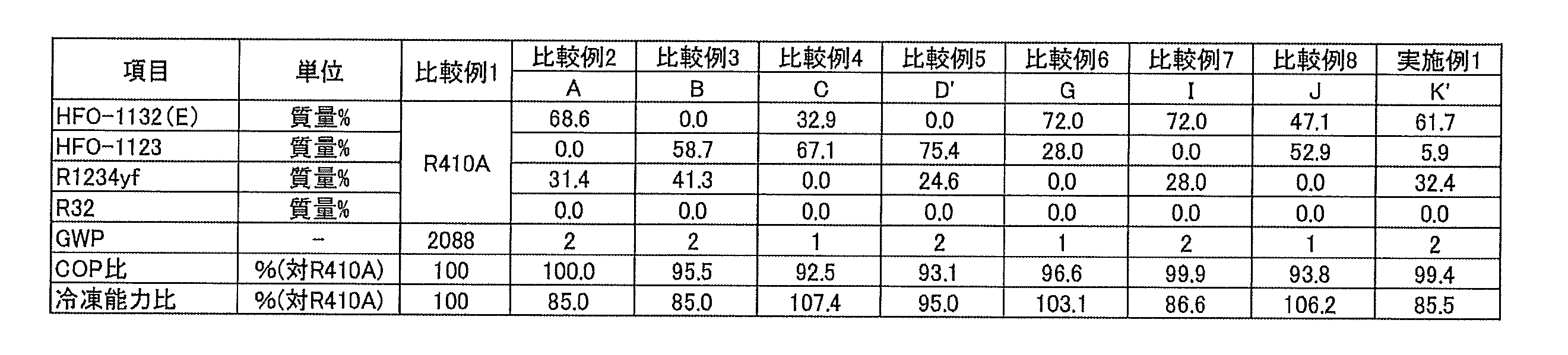


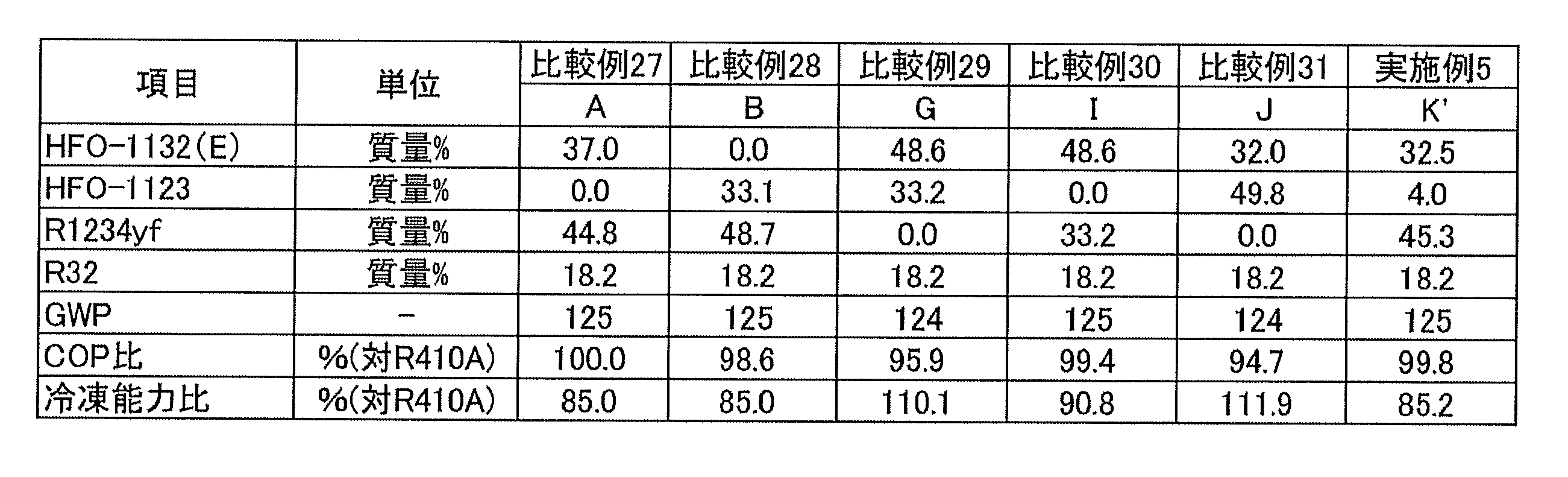
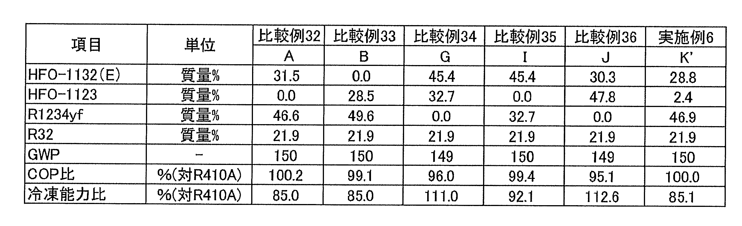

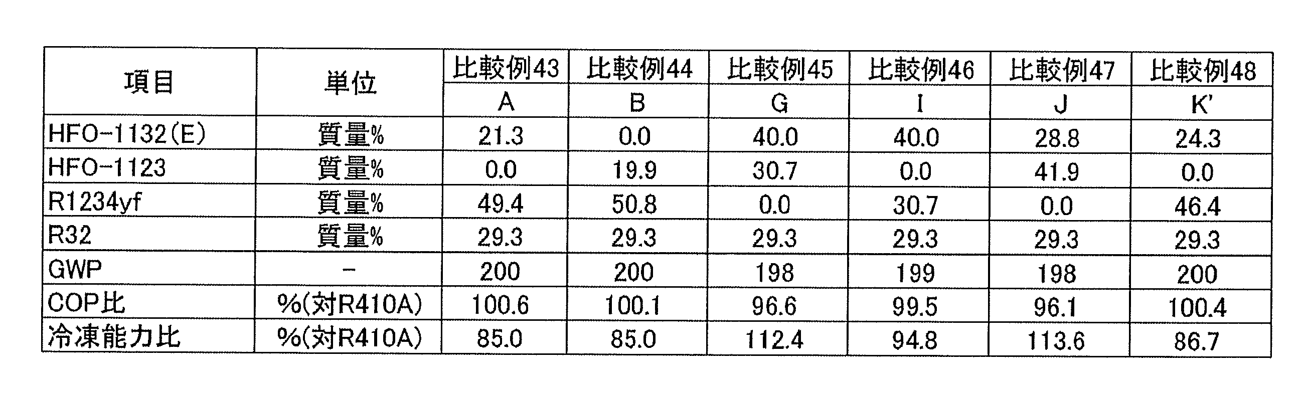
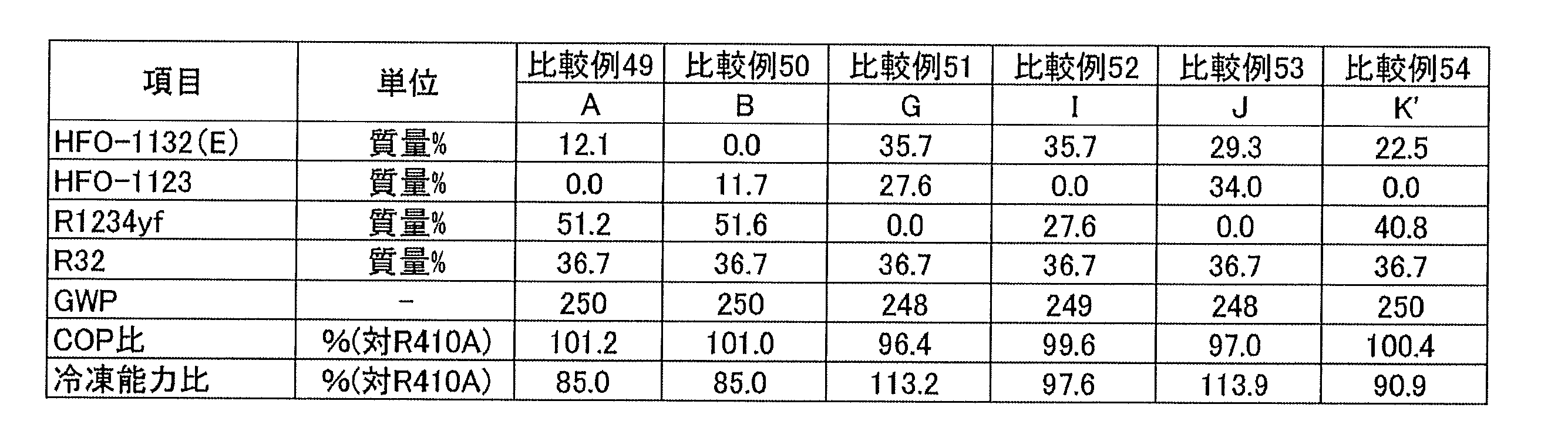


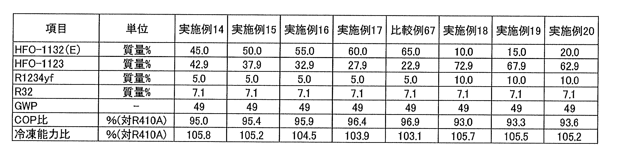


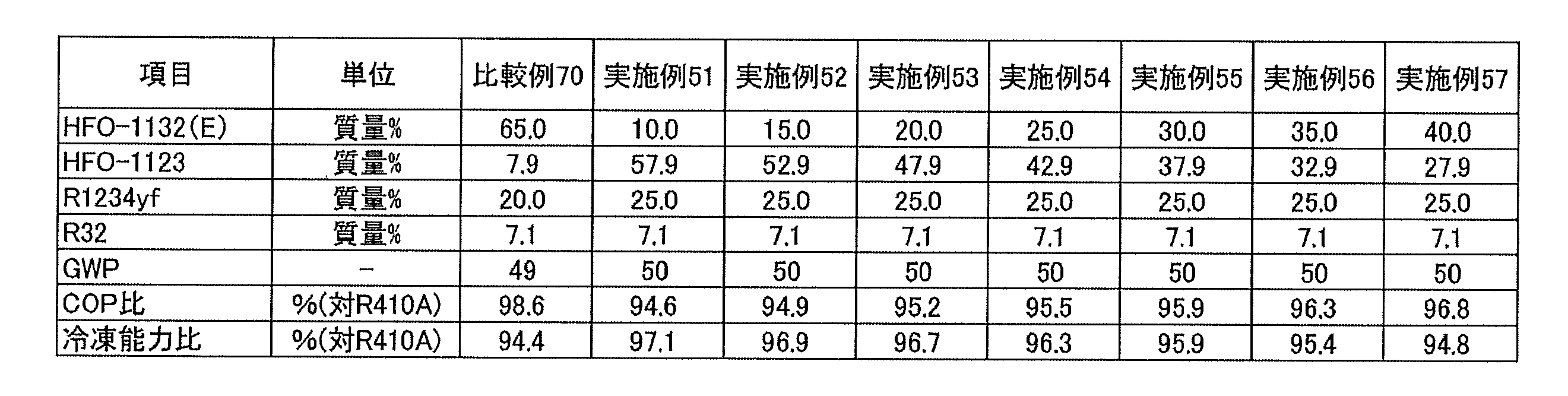


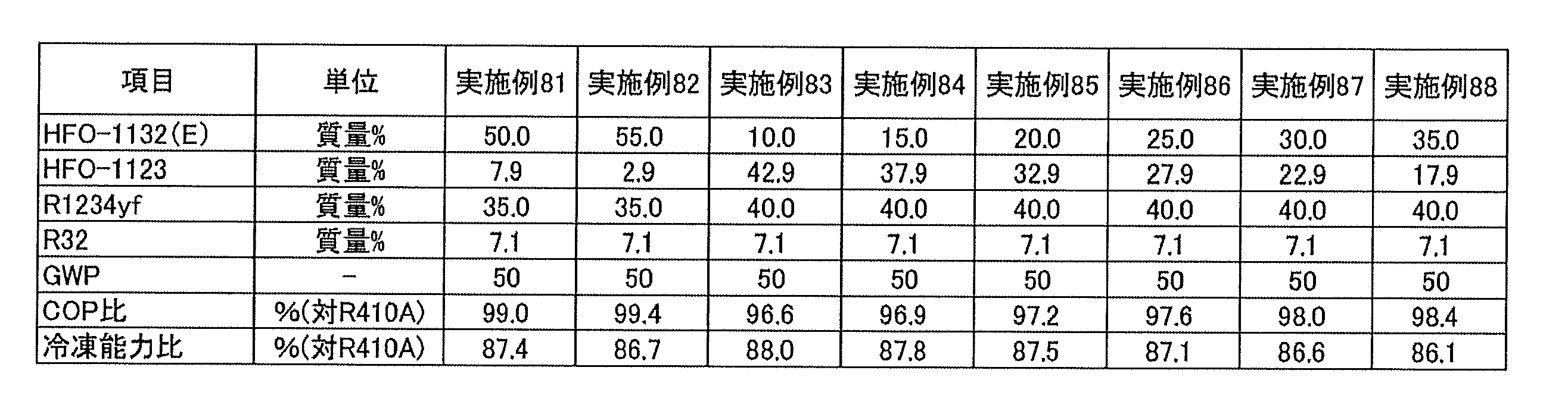
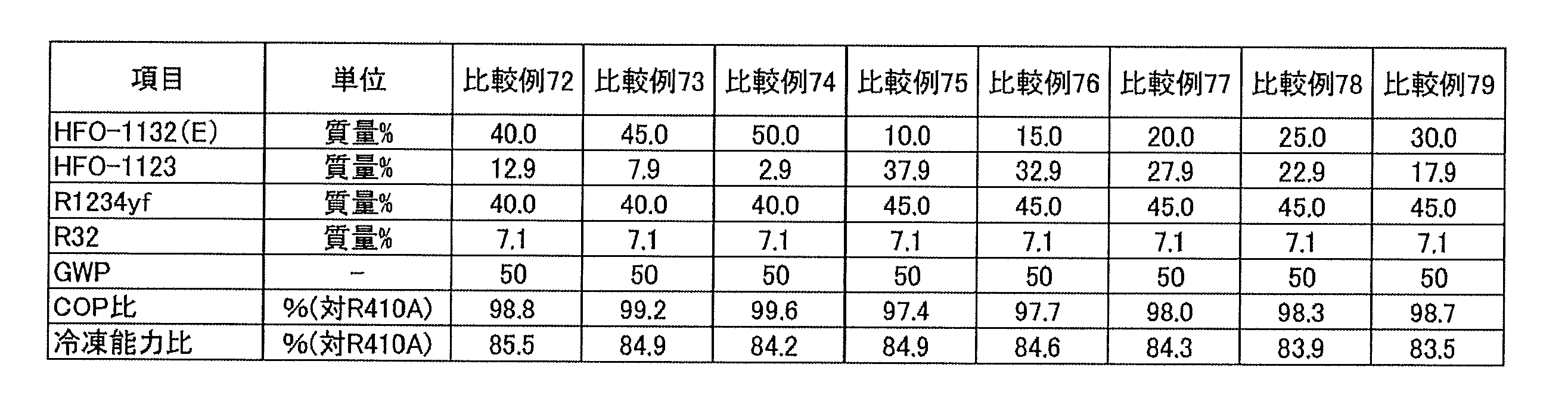

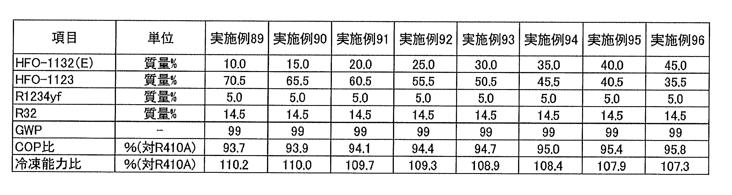


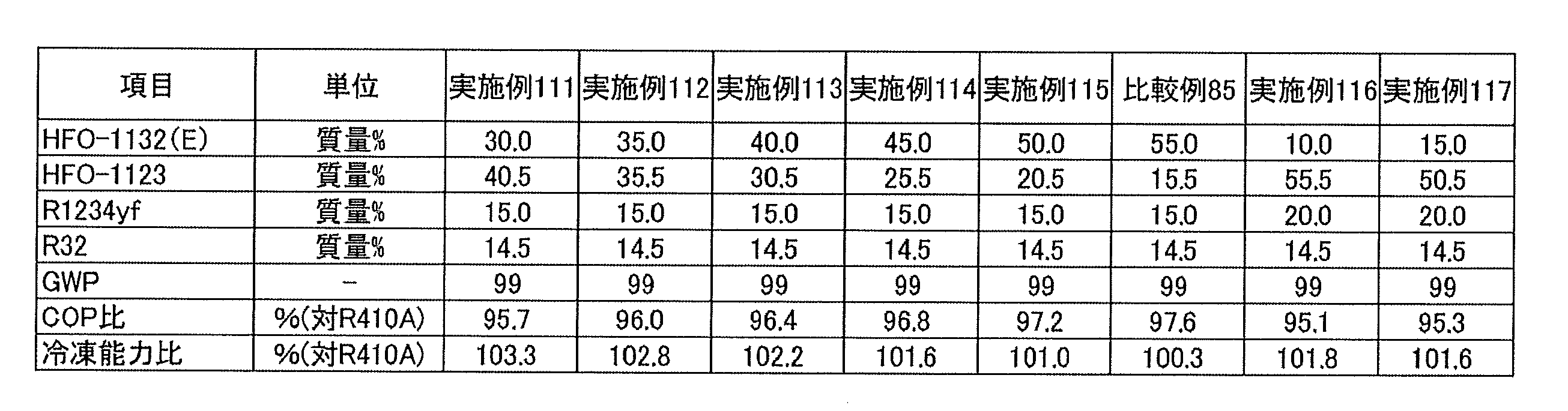

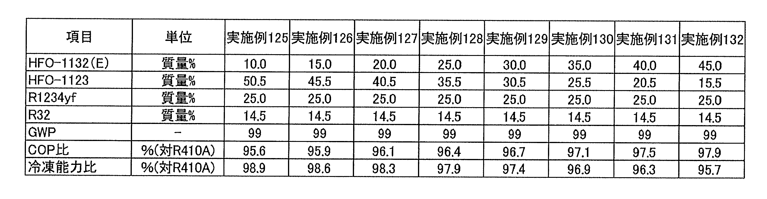


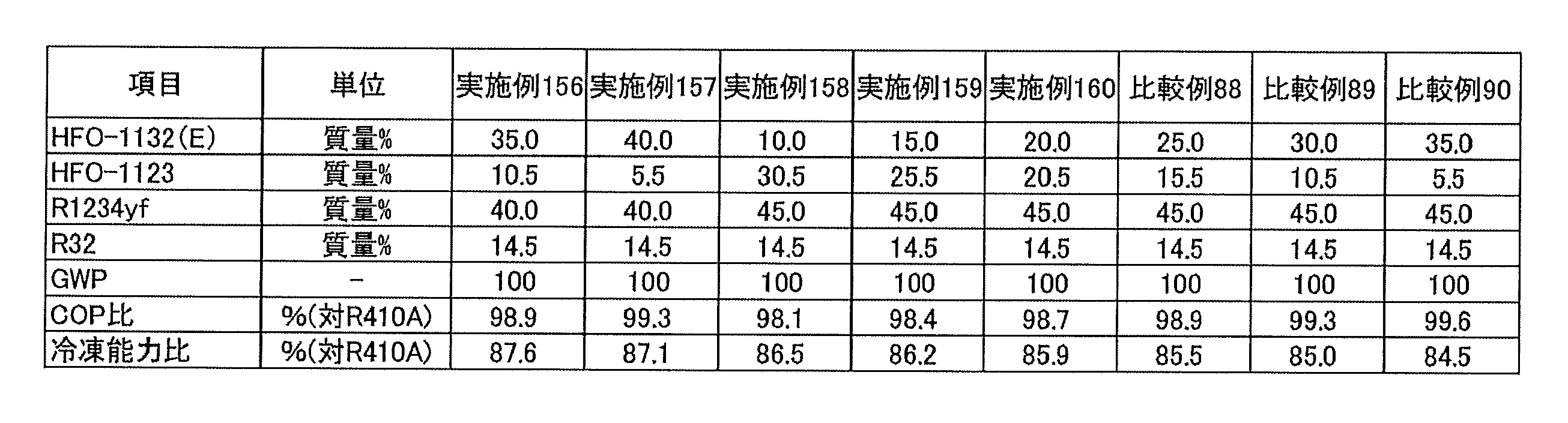


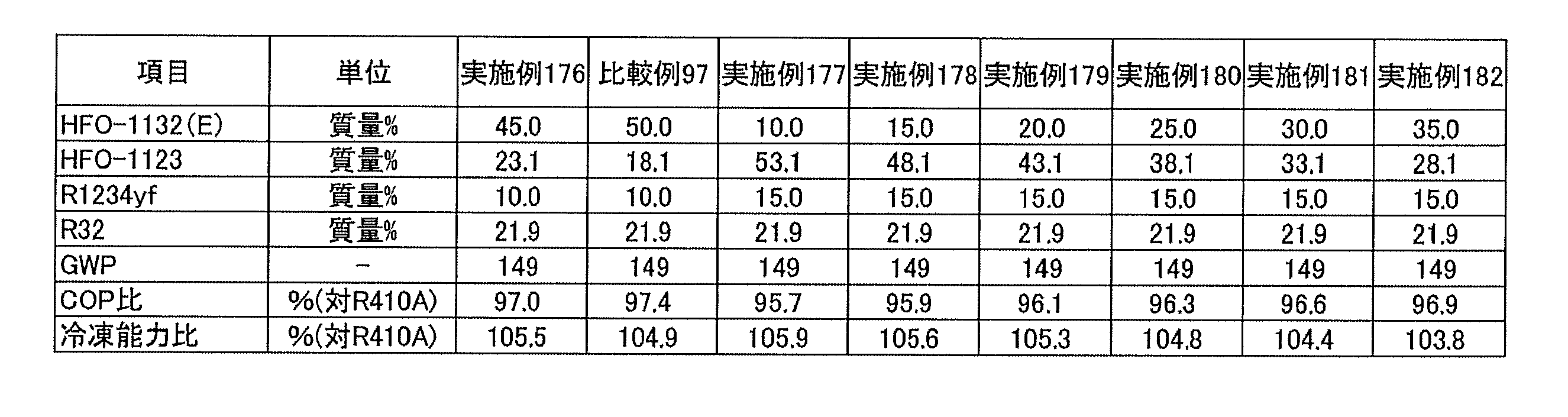


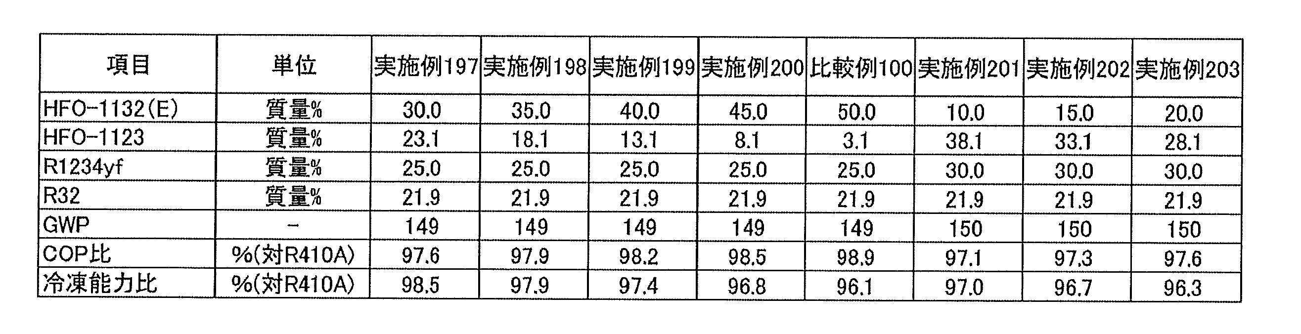

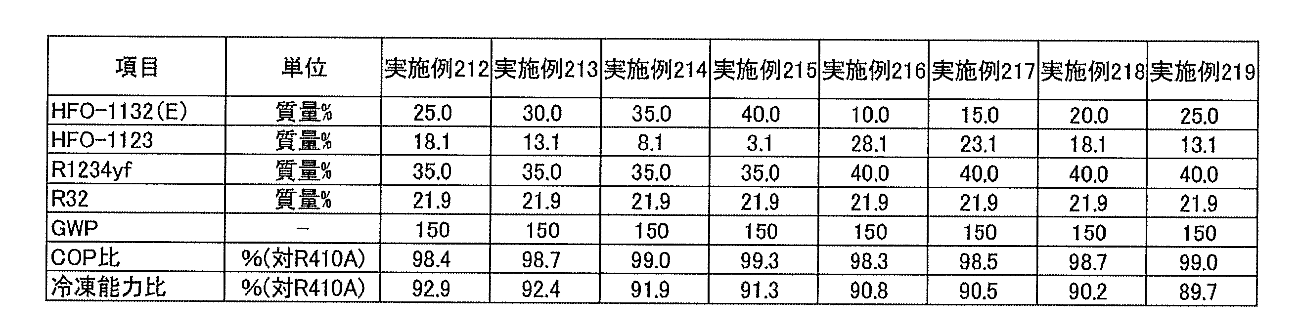
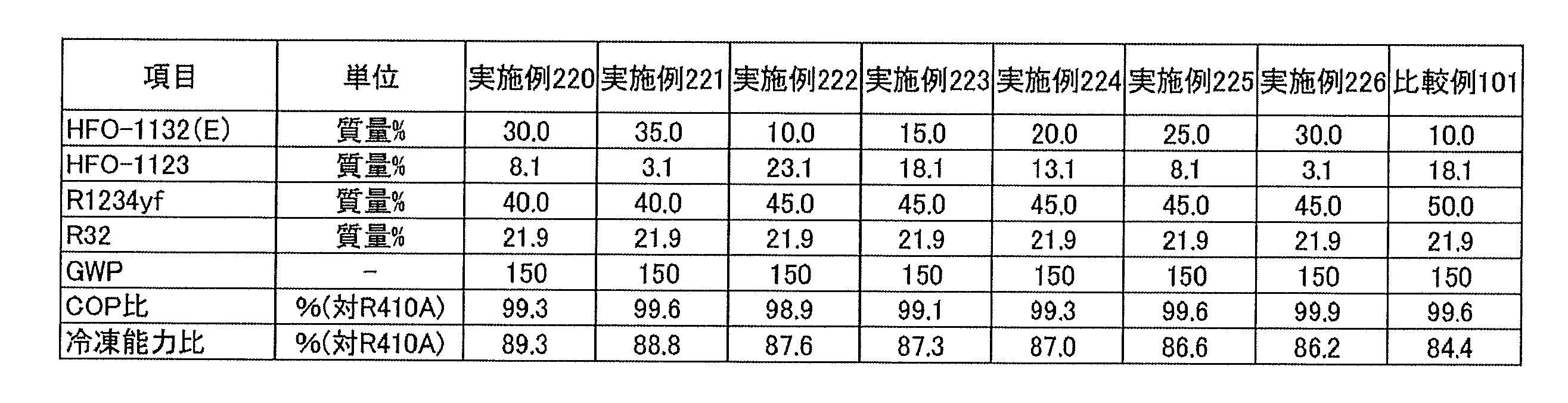

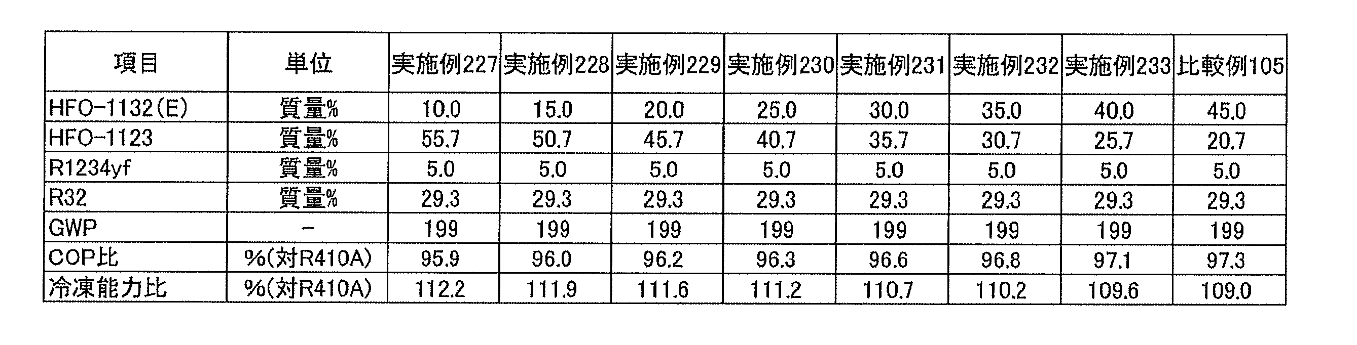


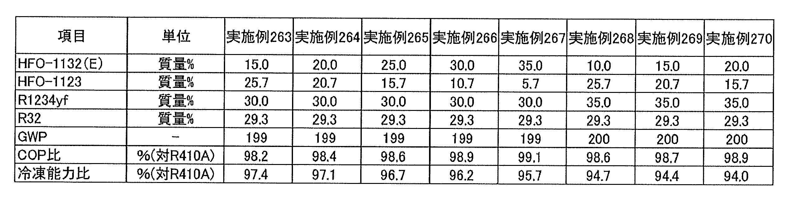


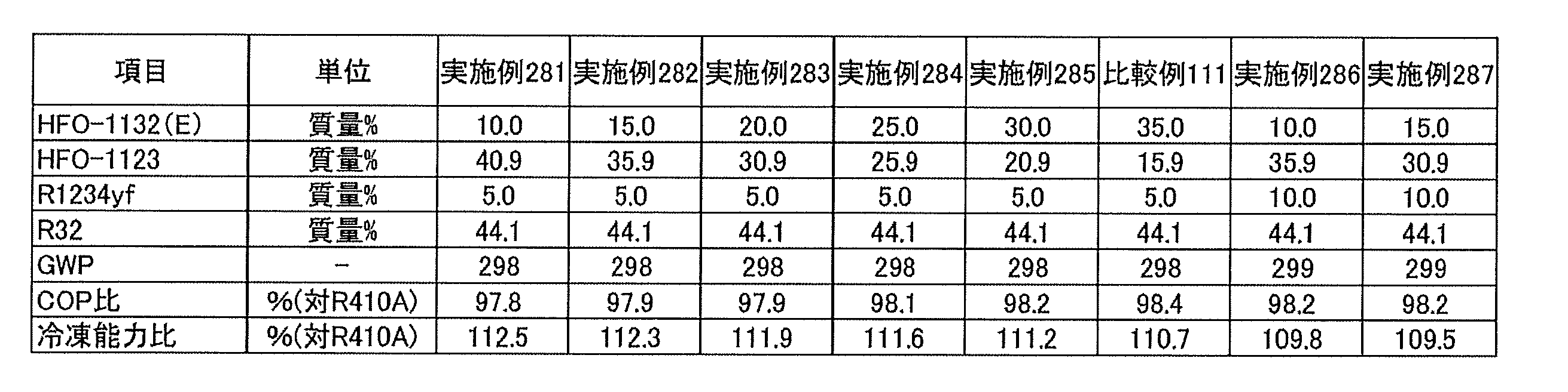


これらの結果から、HFO-1132(E)、HFO-1123及びR1234yf、並びにR32の、これらの総和を基準とする質量%をそれぞれx、y及びz、並びにaとするとき、HFO-1132(E)、HFO-1123及びR1234yfの総和が(100-a)質量%となる、点(0.0, 100.0-a, 0.0)と点(0.0, 0.0, 100,0-a)とを結ぶ直線を底辺とし、かつ点(0.0, 100.0-a, 0.0)が左側となる3成分組成図において、座標(x,y,z)が、
0<a≦11.1のとき、
点A(0.0134a2-1.9681a+68.6, 0.0, -0.0134a2+0.9681a+31.4)と
点B(0.0, 0.0144a2-1.6377a+58.7, -0.0144a2+0.6377a+41.3)と
を結ぶ直線ABの線上又は左側、
11.1<a≦18.2のとき、
点A(0.0112a2-1.9337a+68.484, 0.0, -0.0112a2+0.9337a+31.516)と
点B(0.0, 0.0075a2-1.5156a+58.199, -0.0075a2+0.5156a+41.801)と
を結ぶ直線ABの線上又は左側、
18.2<a≦26.7のとき、
点A(0.0107a2-1.9142a+68.305, 0.0, -0.0107a2+0.9142a+31.695)と
点B(0.0, 0.009a2-1.6045a+59.318, -0.009a2+0.6045a+40.682)と
を結ぶ直線ABの線上又は左側、
26.7<a≦36.7のとき、
点A(0.0103a2-1.9225a+68.793, 0.0, -0.0103a2+0.9225a+31.207)と
点B(0.0, 0.0046a2-1.41a+57.286, -0.0046a2+0.41a+42.714)と
を結ぶ直線ABの線上又は左側、並びに
36.7<a≦46.7のとき、
点A(0.0085a2-1.8102a+67.1, 0.0, -0.0085a2+0.8102a+32.9)と
点B(0.0, 0.0012a2-1.1659a+52.95, -0.0012a2+0.1659a+47.05)と
を結ぶ直線ABの線上又は左側にある場合に、R410Aを基準とする冷凍能力比が85%以上となることが判る。なお、実際の冷凍能力比85%の点は、図3に示す点A、点Bを結ぶ1234yf側に広がった曲線となる。従って、直線ABの線上又は左側にある場合に、R410Aを基準とする冷凍能力比が85%以上となる。 From these results, HFO-1132 (E: HFO-1132 (E), HFO-1123 and R1234yf, and R32, based on the sum of these, mass% is x, y and z, and a, respectively). , HFO-1123 and R1234yf, the bottom line is a straight line connecting point (0.0, 100.0-a, 0.0) and point (0.0, 0.0, 100, 0-a) where the mass becomes (100-a) mass% And in the three-component composition diagram where the point (0.0, 100.0-a, 0.0) is on the left, the coordinates (x, y, z) are
When 0 <a ≦ 11.1
Point A (0.0134a 2 -1.9681a + 68.6, 0.0, -0.0134a 2 + 0.9681a + 31.4) and point B (0.0, 0.0144a 2 -1.6377a + 58.7, -0.0144a 2 + 0.6377a + 41.3) and A straight line AB connecting the
When 11.1 <a ≦ 18.2
Point A (0.0112a 2 -1.9337a + 68.484, 0.0,-0.0112a 2 + 0.9337a + 31.516) and point B (0.0, 0.0075a 2 -1.5156a + 58.199, -0.0075a 2 + 0.5156a + 41.801) and A straight line AB connecting the
When 18.2 <a ≦ 26.7
Point A (0.0107a 2 -1.9142a + 68.305, 0.0, -0.0107a 2 + 0.9142a + 31.695) and point B (0.0, 0.009a 2 -1.6045a + 59.318, -0.009a 2 + 0.6045a + 40.682) and A straight line AB connecting the
When 26.7 <a ≦ 36.7
Point A (0.0103a 2 -1.9225a + 68.793, 0.0, -0.0103a 2 + 0.9225a + 31.207) and point B (0.0, 0.0046a 2 -1.41a + 57.286, -0.0046a 2 + 0.41a + 42.714) and And the left side of a straight line AB connecting the two, and when 36.7 <a ≦ 46.7,
Point A (0.0085a 2 -1.8102a + 67.1, 0.0, -0.0085a 2 + 0.8102a + 32.9) and point B (0.0, 0.0012a 2 -1.1659a + 52.95, -0.0012a 2 + 0.1659a + 47.05) and It can be seen that the refrigeration capacity ratio based on R410A is 85% or more when it is on the straight line AB connecting the two or on the left side. A point at which the actual refrigeration capacity ratio is 85% is a curve that extends to the 1234yf side connecting the point A and the point B shown in FIG. Therefore, when it is on the straight line AB or on the left side, the refrigeration capacity ratio based on R410A is 85% or more.
同様に、上記3成分組成図において、座標(x,y,z)が、
0<a≦11.1のとき、
点D’(0.0, 0.0224a2+0.968a+75.4, -0.0224a2-1.968a+24.6)と
点C(-0.2304a2-0.4062a+32.9, 0.2304a2-0.5938a+67.1, 0.0)と
を結ぶ直線D’Cの線上又は右側にある場合に、また、
11.1<a≦46.7のとき、
全ての領域内にある場合に、R410Aを基準とするCOP比が92.5%以上となることが判る。 Similarly, in the above three-component composition diagram, the coordinates (x, y, z) are
When 0 <a ≦ 11.1
Point D '(0.0, 0.0224a 2 + 0.968a + 75.4, -0.0224a 2 -1.968a + 24.6) and point C (-0.2304a 2 -0.4062a + 32.9, 0.2304a 2 -0.5938a + 67.1, 0.0) And the straight line D′ C connecting the
When 11.1 <a ≦ 46.7
It can be seen that the COP ratio based on R410A is 92.5% or more when in all the regions.
なお、図3においてCOP比が92.5%以上となるのは曲線CDであるが、図3ではR1234yf濃度が5質量%、10質量%のときにCOP比が92.5%となる点(26.6, 68.4,5),(19.5, 70.5, 10)、及び点C(32.9, 67.1, 0.0)の3点を結ぶ近似直線を求め、HFO-1132(E)濃度が0.0質量%との交点D’(0, 75.4, 24.6)と点Cを結ぶ直線を線分D’Cとした。また、図4では、COP比が92.5%となる点C(18.4, 74.5,0)、点(13.9, 76.5, 2.5)、点(8.7, 79.2, 5)を結ぶ近似曲線から同様にD’(0, 83.4, 9.5)を求め、点Cと結ぶ直線をD’Cとした。
In FIG. 3, it is the curve CD that the COP ratio is 92.5% or more, but in FIG. 3, when the R1234yf concentration is 5% by mass and 10% by mass, the COP ratio is 92.5% (26.6, 68.4, 5), (19.5, 70.5, 10), and an approximate straight line connecting three points C (32.9, 67.1, 0.0), and the intersection point D ′ (0, 0, 0) with the HFO-1132 (E) concentration of 0.0 mass% A straight line connecting 75.4, 24.6) and the point C is a line segment D'C. Also, in FIG. 4, D ′ (D) is similarly derived from an approximate curve connecting point C (18.4, 74.5, 0), point (13.9, 76.5, 2.5), and point (8.7, 79. Find 0, 83.4, 9.5), and let D'C be a straight line connecting point C.
また、各混合物の組成をWCFとし、ASHRAE34-2013規格に従って装置(Equipment)、貯蔵(Storage)、輸送(Shipping)、漏洩(Leak)及び再充填(Recharge)の条件でNIST Standard Reference Data Base Refleak Version 4.0により漏洩シミュレーションを行い、最も燃えやすい分画(fraction)をWCFFとした。また、燃焼性はANSI/ASHRAE34-2013規格に従い燃焼速度を測定した。燃焼速度がWCF及びWCFFともに10 cm/s以下となるものは「2Lクラス(微燃性)」であるとした。
In addition, the composition of each mixture is WCF, and NIST Standard Reference Data Base Version under the condition of Equipment, Storage, Shipping, Leak, and Recharge according to ASHRAE 34-2013 standard. A leak simulation was performed according to 4.0, and the most flammable fraction was WCFF. In addition, the flammability was measured according to the ANSI / ASHRAE 34-2013 standard. If the burning rate is 10 cm / s or less for both WCF and WCFF, it is considered as "2 L class (slight flammability)".
なお、燃焼速度試験は図1に示す装置を用いて、以下の通り行った。まず、使用した混合冷媒は99.5%またはそれ以上の純度とし、真空ゲージ上に空気の痕跡が見られなくなるまで凍結、ポンピング及び解凍のサイクルを繰り返すことにより脱気した。閉鎖法により燃焼速度を測定した。初期温度は周囲温度とした。点火は、試料セルの中心で電極間に電気的スパークを生じさせることにより行った。放電の持続時間は1.0~9.9msとし、点火エネルギーは典型的には約0.1~1.0Jであった。シュリーレン写真を使って炎の広がりを視覚化した。光を通す2つのアクリル窓を備えた円筒形容器(内径:155mm、長さ:198mm)を試料セルとして用い、光源としてはキセノンランプを用いた。炎のシュリーレン画像を高速デジタルビデオカメラで600fpsのフレーミング速度で記録し、PCに保存した。
In addition, the burning rate test was done as follows using the apparatus shown in FIG. First, the mixed refrigerant used was 99.5% or more pure and degassed by repeated cycles of freezing, pumping and thawing until no traces of air were visible on the vacuum gauge. The burning rate was measured by the closure method. The initial temperature was ambient temperature. Ignition was performed by creating an electrical spark between the electrodes at the center of the sample cell. The duration of the discharge was 1.0 to 9.9 ms, and the ignition energy was typically about 0.1 to 1.0 J. The spread of the flame was visualized using Schlieren photographs. A cylindrical container (inner diameter: 155 mm, length: 198 mm) equipped with two acrylic windows for transmitting light was used as a sample cell, and a xenon lamp was used as a light source. Schlieren images of flames were recorded with a high speed digital video camera at a framing rate of 600 fps and stored on a PC.
結果を表97~104に示す。
The results are shown in Tables 97-104.
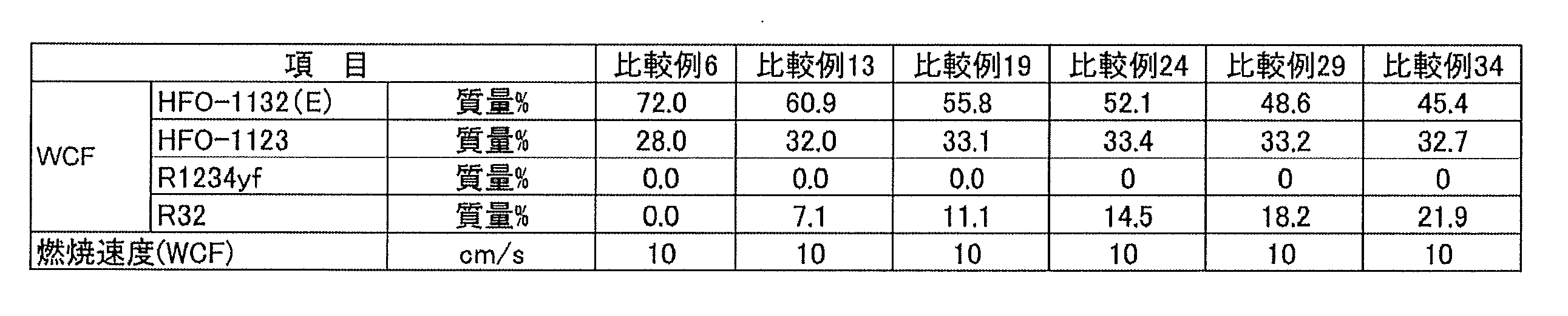

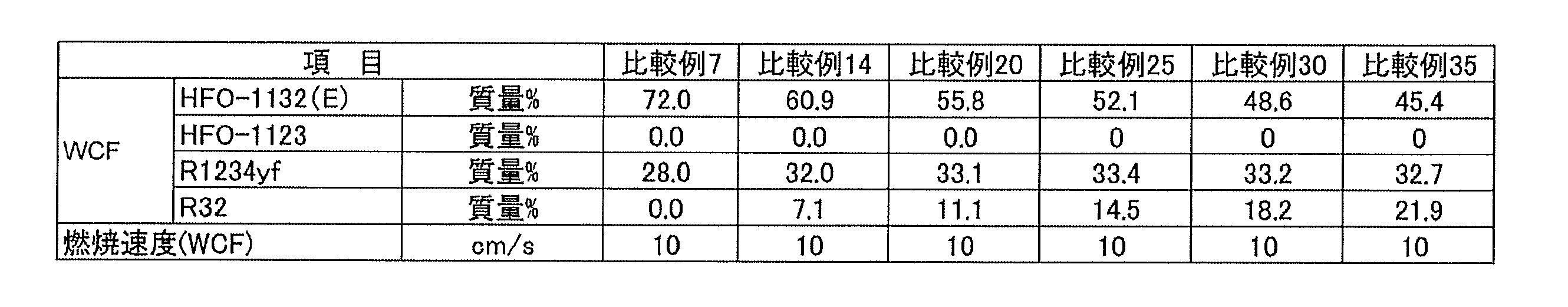


表97~100の結果から、HFO-1132(E)、HFO-1123及びR1234yf、並びにR32の混合冷媒においては、HFO-1132(E)、HFO-1123及びR1234yf、並びにR32の、これらの総和を基準とする質量%をそれぞれx、y及びz、並びにaとするとき、HFO-1132(E)、HFO-1123及びR1234yfの総和が(100-a)質量%となる、点(0.0,100.0-a, 0.0)と点(0.0, 0.0, 100,0-a)とを結ぶ直線を底辺とする3成分組成図において、
0<a≦11.1のとき、
点G(0.026a2-1.7478a+72.0, -0.026a2+0.7478a+28.0, 0.0)と
点I(0.026a2-1.7478a+72.0, 0.0, -0.026a2+0.7478a+28.0)と
を結ぶ直線GIの線上又は下、
11.1<a≦18.2のとき、
点G(0.02a2-1.6013a+71.105, -0.02a2+0.6013a+28.895, 0.0)と
点I(0.02a2-1.6013a+71.105, 0.0, -0.02a2+0.6013a+28.895)と
を結ぶ直線GIの線上又は下、
18.2<a≦26.7のとき、
点G(0.0135a2-1.4068a+69.727, -0.0135a2+0.4068a+30.273, 0.0)と
点I(0.0135a2-1.4068a+69.727, 0.0, -0.0135a2+0.4068a+30.273)と
を結ぶ直線GIの線上又は下、
26.7<a≦36.7のとき、
点G(0.0111a2-1.3152a+68.986, -0.0111a2+0.3152a+31.014, 0.0)と
点I(0.0111a2-1.3152a+68.986, 0.0, -0.0111a2+0.3152a+31.014)と
を結ぶ直線GIの線上又は下、及び
36.7<a≦46.7のとき、
点G(0.0061a2-0.9918a+63.902, -0.0061a2-0.0082a+36.098,0.0)と
点I(0.0061a2-0.9918a+63.902, 0.0, -0.0061a2-0.0082a+36.098)と
を結ぶ直線GIの線上又は下にある場合に、WCF微燃性と判断できることが明らかとなった。なお、点G(表105)及びI(表106)は、計算により以下の5範囲毎に三点ずつを求め、これらの近似式を求めた。 From the results of Tables 97 to 100, in the case of a mixed refrigerant of HFO-1132 (E), HFO-1123 and R1234yf, and R32, the sum of HFO-1132 (E), HFO-1123 and R1234yf, and R32 is obtained. Assuming that the reference mass% is x, y and z, and a, respectively, the sum of HFO-1132 (E), HFO-1123 and R1234yf becomes (100−a) mass%, a point (0.0, 100.0 − In a three-component composition diagram in which a straight line connecting a, 0.0) and a point (0.0, 0.0, 100, 0-a) is a base:
When 0 <a ≦ 11.1
Point G (0.026a 2 -1.7478a + 72.0, -0.026a 2 + 0.7478a + 28.0, 0.0) and point I (0.026a 2 -1.7478a + 72.0, 0.0, -0.026a 2 + 0.7478a + 28.0) and Or below the straight line GI connecting
When 11.1 <a ≦ 18.2
Point G (0.02a 2 -1.6013a + 71.105, -0.02a 2 + 0.6013a + 28.895, 0.0) and point I (0.02a 2 -1.6013a + 71.105, 0.0, -0.02a 2 + 0.6013a + 28.895) Or below the straight line GI connecting
When 18.2 <a ≦ 26.7
Point G (0.0135a 2 -1.4068a + 69.727, -0.0135a 2 + 0.4068a + 30.273, 0.0) and point I (0.0135a 2 -1.4068a + 69.727, 0.0, -0.0135a 2 + 0.4068a + 30.273) and Or below the straight line GI connecting
When 26.7 <a ≦ 36.7
Point G (0.0111a 2 -1.3152a + 68.986, -0.0111a 2 + 0.3152a + 31.014, 0.0) and point I (0.0111a 2 -1.3152a + 68.986, 0.0, -0.0111a 2 + 0.3152a + 31.014) and On or below the straight line GI connecting the two and when 36.7 <a ≦ 46.7,
Point G (0.0061a 2 -0.9918a + 63.902, -0.0061a 2 -0.0082a + 36.098,0.0) and point I (0.0061a 2 -0.9918a + 63.902, 0.0, -0.0061a 2 -0.0082a + 36.098) and It became clear that it could be judged as WCF slight flammability when it was on or below the straight line GI connecting. In addition, the point G (Table 105) and I (Table 106) calculated | required three points for every 5 range of following by calculation, and calculated | required these approximation formulas.


表101~104の結果から、HFO-1132(E)、HFO-1123及びR1234yf、並びにR32の混合冷媒においては、HFO-1132(E)、HFO-1123及びR1234yf、並びにR32の、これらの総和を基準とする質量%をそれぞれx、y及びz、並びにaとするとき、HFO-1132(E)、HFO-1123及びR1234yfの総和が(100-a)質量%となる、点(0.0,100.0-a, 0.0)と点(0.0, 0.0, 100,0-a)とを結ぶ直線を底辺とする3成分組成図において、
0<a≦11.1のとき、
点J(0.0049a2-0.9645a+47.1, -0.0049a2-0.0355a+52.9, 0.0)と
点K’(0.0514a2-2.4353a+61.7, -0.0323a2+0.4122a+5.9, -0.0191a2+1.0231a+32.4)と
を結ぶ直線JK’の線上又は下、
11.1<a≦18.2のとき、
点J(0.0243a2-1.4161a+49.725, -0.0243a2+0.4161a+50.275, 0.0)と
点K’(0.0341a2-2.1977a+61.187, -0.0236a2+0.34a+5.636, -0.0105a2+0.8577a+33.177)と
を結ぶ直線JK’の線上又は下、
18.2<a≦26.7のとき、
点J(0.0246a2-1.4476a+50.184, -0.0246a2+0.4476a+49.816, 0.0)と
点K’(0.0196a2-1.7863a+58.515, -0.0079a2-0.1136a+8.702, -0.0117a2+0.8999a+32.783)とを結ぶ直線JK’の線上又は下、
26.7<a≦36.7のとき、
点J(0.0183a2-1.1399a+46.493, -0.0183a2+0.1399a+53.507, 0.0)と
点K’(-0.0051a2+0.0929a+25.95, 0.0, 0.0051a2-1.0929a+74.05)と
を結ぶ直線JK’の線上又は下、及び
36.7<a≦46.7のとき、
点J(-0.0134a2+1.0956a+7.13, 0.0134a2-2.0956a+92.87, 0.0)と
点K’(-1.892a+29.443, 0.0, 0.892a+70.557)と
を結ぶ直線JK’の線上又は下にある場合に、WCFF微燃性と判断でき、ASHRAE規格の燃焼性分類で「2L(微燃性)」になることが明らかとなった。 From the results of Tables 101 to 104, in the case of a mixed refrigerant of HFO-1132 (E), HFO-1123 and R1234yf, and R32, the sum of HFO-1132 (E), HFO-1123 and R1234yf, and R32 is obtained. Assuming that the reference mass% is x, y and z, and a, respectively, the sum of HFO-1132 (E), HFO-1123 and R1234yf becomes (100−a) mass%, a point (0.0, 100.0 − In a three-component composition diagram in which a straight line connecting a, 0.0) and a point (0.0, 0.0, 100, 0-a) is a base:
When 0 <a ≦ 11.1
Point J (0.0049a 2 -0.9645a + 47.1, -0.0049a 2 -0.0355a + 52.9, 0.0) and the point K '(0.0514a 2 -2.4353a + 61.7 , -0.0323a 2 + 0.4122a + 5.9, -0.0191 a line on or below a straight line JK ′ connecting a 2 + 1.0231a + 32.4),
When 11.1 <a ≦ 18.2
Point J (0.0243a 2 -1.4161a + 49.725, -0.0243a 2 + 0.4161a + 50.275, 0.0) and point K '(0.0341a 2 -2.1977a + 61.187, -0.0236a 2 + 0.34a + 5.636, -0.0105 line or under a 2 + 0.8577a + 33.177) and the straight line JK 'connecting,
When 18.2 <a ≦ 26.7
Point J (0.0246a 2 -1.4476a + 50.184, -0.0246a 2 + 0.4476a + 49.816, 0.0) and point K '(0.0196a 2 -1.7863a + 58.515, -0.0079a 2 -0.1136a + 8.702, -0. 017 line or under a 2 + 0.8999a + 32.783) and the straight line JK 'connecting,
When 26.7 <a ≦ 36.7
Point J (0.0183a 2 -1.1399a + 46.493, -0.0183a 2 + 0.1399a + 53.507, 0.0) and the point K '(- 0.0051a 2 + 0.0929a + 25.95, 0.0, 0.0051a 2 -1.0929a + 74.05) And a straight line JK ′ connecting the two or more, and when 36.7 <a ≦ 46.7,
Point J (-0.0134a 2 + 1.0956a + 7.13 , 0.0134a 2 -2.0956a + 92.87, 0.0) and point K - lines of '(1.892a + 29.443, 0.0, 0.892a + 70.557) straight JK connecting the' Or when it is below, it can be judged as WCFF slight flammability, and it became clear to become "2 L (slight flammability)" in the flammability classification of ASHRAE standard.
なお、実際のWCFF微燃の点は、図3に示す点J、点K’(直線AB上)を結ぶHFO-1132(E)側に広がった曲線となる。従って、直線JK’の線上又は下側にある場合にはWCFF微燃性となる。
In addition, the point of the actual WCFF slight combustion becomes a curve which spreads to the HFO-1132 (E) side connecting the point J and the point K '(on the straight line AB) shown in FIG. Therefore, when it is on the line of straight line JK 'or below, it becomes WCFF slight flame retardance.
なお、点J(表107)及びK’(表108)は、計算により以下の5範囲毎に三点ずつを求め、これらの近似式を求めた。
In addition, the point J (Table 107) and K '(Table 108) calculated | required three points for every 5 range of following by calculation, and calculated | required these approximation formulas.
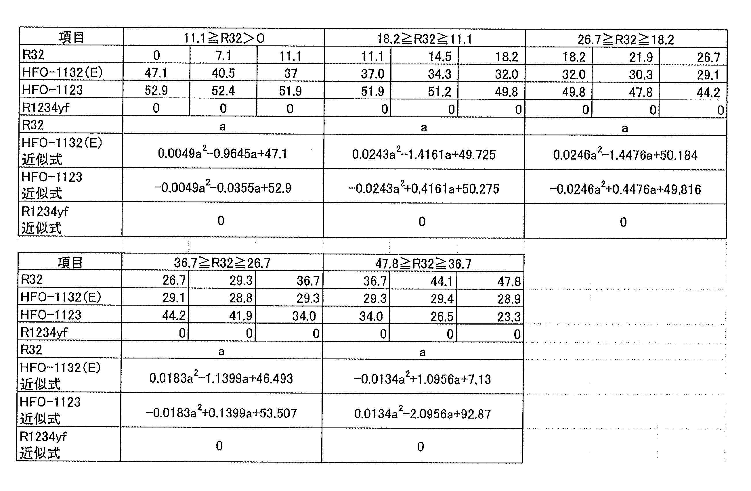

なお、図3~13は、それぞれ、順に、R32含有割合a(質量%)が、0質量%、7.1質量%、11.1質量%、14.5質量%、18.2質量%、21.9質量%、26.7質量%、29.3質量%、36.7質量%、44.1質量%及び47.8質量%の場合の組成を表わしている。
3 to 13, respectively, the R32 content ratio a (mass%) is 0 mass%, 7.1 mass%, 11.1 mass%, 14.5 mass%, 18.2 mass%, 21.9 mass%, 26.7 mass%, respectively. The compositions are shown for 29.3% by weight, 36.7% by weight, 44.1% by weight and 47.8% by weight.
点A、B、C、D’は、近似計算によりそれぞれ以下のようにして求めた。
The points A, B, C, and D 'were determined by approximation calculation as follows.
点Aは、HFO-1123含有割合が0質量%であり、かつR410Aを基準とする冷凍能力比が85%となる点である。点Aについて、計算により以下の5範囲毎に三点ずつを求め、これらの近似式を求めた(表109)。
Point A is a point where the HFO-1123 content is 0% by mass and the refrigeration capacity ratio based on R410A is 85%. With respect to the point A, three points were obtained for each of the following five ranges by calculation, and their approximate expressions were obtained (Table 109).
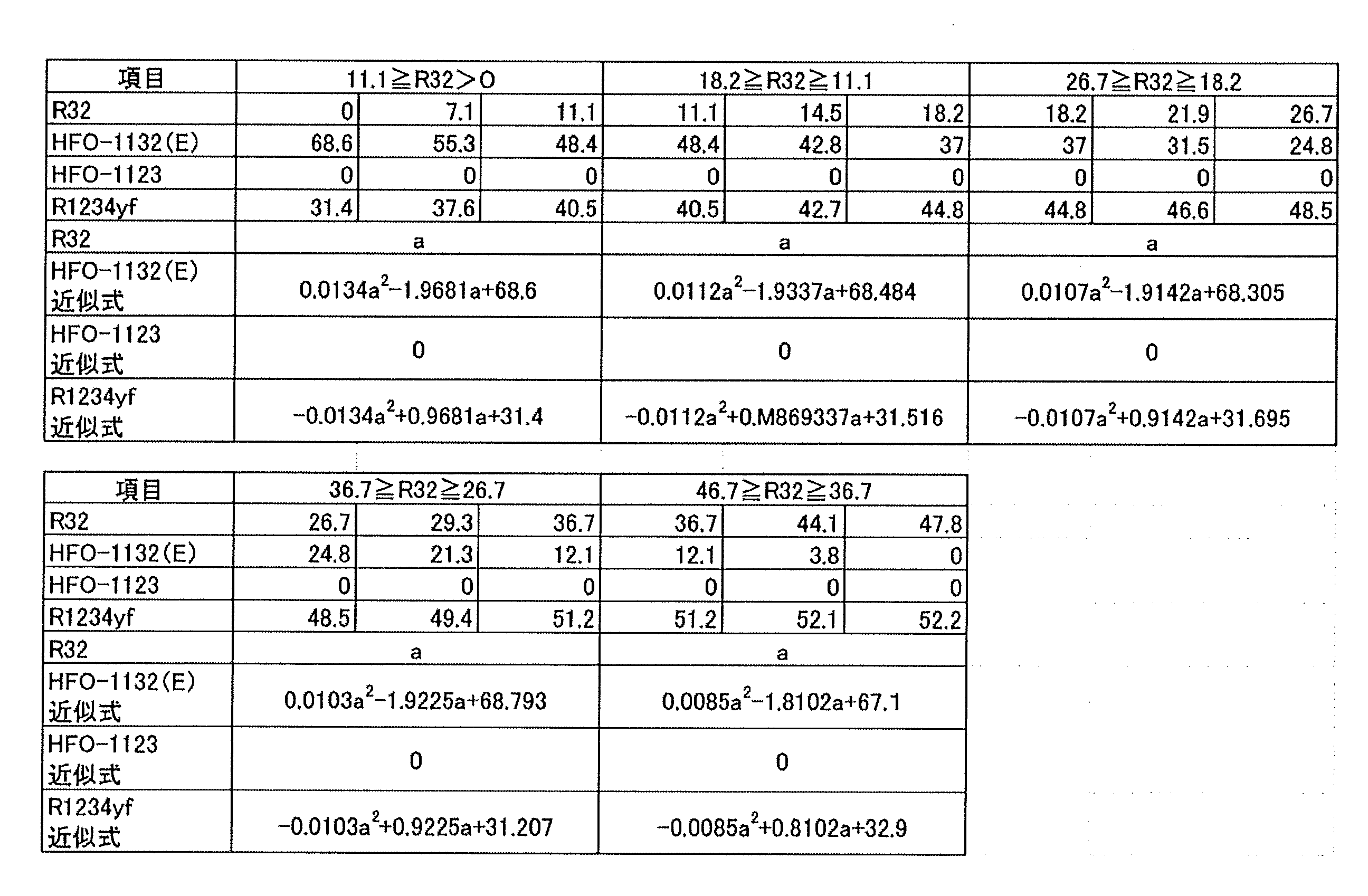
点Bは、HFO-1132(E)含有割合が0質量%であり、かつR410Aを基準とする冷凍能力比が85%となる点である。点Bについて、計算により以下の5範囲毎に三点ずつを求め、これらの近似式を求めた(表110)。
Point B is a point at which the HFO-1132 (E) content rate is 0% by mass and the refrigeration capacity ratio based on R410A is 85%. For the point B, three points were obtained for each of the following five ranges by calculation, and their approximate expressions were obtained (Table 110).

点D’は、HFO-1132(E)含有割合が0質量%であり、かつR410Aを基準とするCOP比が95.5%となる点である。点D’について、計算により以下の三点ずつを求め、これらの近似式を求めた(表111)。
The point D 'is a point at which the HFO-1132 (E) content rate is 0% by mass and the COP ratio based on R410A is 95.5%. For the point D ', the following three points were obtained by calculation and their approximate expressions were obtained (Table 111).
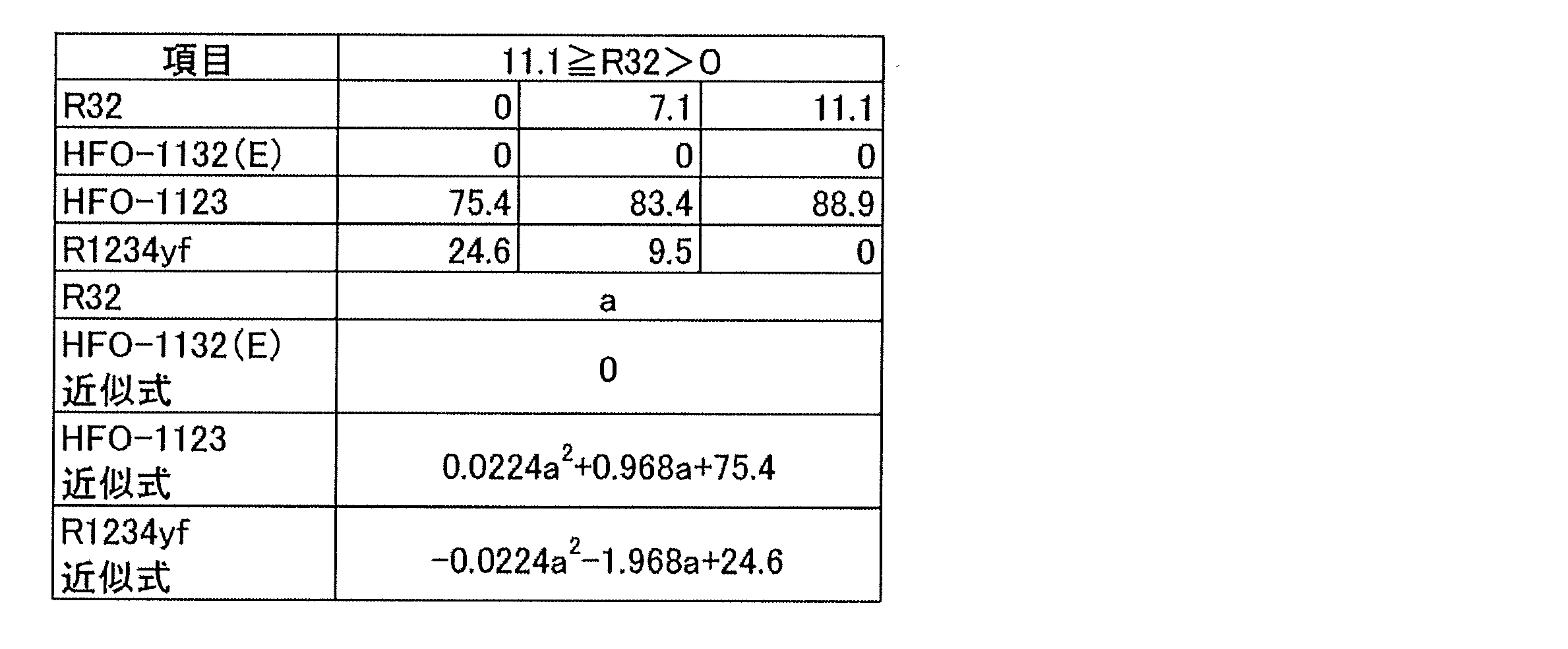
点Cは、R1234yf含有割合が0質量%であり、かつR410Aを基準とするCOP比が95.5%となる点である。点Cについて、計算により以下の三点ずつを求め、これらの近似式を求めた(表112)。
Point C is a point where the R1234yf content rate is 0% by mass and the COP ratio based on R410A is 95.5%. For point C, the following three points were obtained by calculation, and their approximate expressions were obtained (Table 112).

(5-4)冷媒D
本開示の冷媒Dは、トランス-1,2-ジフルオロエチレン(HFO-1132(E))、ジフルオロメタン(R32)及び2,3,3,3-テトラフルオロ-1-プロペン(R1234yf)を含む混合冷媒である。 (5-4) Refrigerant D
The refrigerant D of the present disclosure is a mixture containing trans-1,2-difluoroethylene (HFO-1132 (E)), difluoromethane (R32) and 2,3,3,3-tetrafluoro-1-propene (R1234yf). It is a refrigerant.
本開示の冷媒Dは、R410Aと同等の冷却能力を有し、GWPが十分に小さく、かつASHRAEの規格で微燃性(2Lクラス)である、という、R410A代替冷媒として望ましい諸特性を有する。
The refrigerant D of the present disclosure has desirable characteristics as an R410A alternative refrigerant, having a cooling capacity equivalent to that of R410A, a sufficiently small GWP, and a slight flammability (2 L class) according to the ASHRAE standard.
本開示の冷媒Dは、HFO-1132(E)、R32及びR1234yfの、これらの総和を基準とする質量%をそれぞれx、y及びzとするとき、HFO-1132(E)、R32及びR1234yfの総和が100質量%となる3成分組成図において、座標(x,y,z)が、
点I(72.0, 0.0, 28.0)、
点J(48.5, 18.3, 33.2)、
点N(27.7, 18.2, 54.1)及び
点E(58.3, 0.0, 41.7)
の4点をそれぞれ結ぶ線分IJ、JN、NE、及びEIで囲まれる図形の範囲内又は前記線分上にあり(ただし、線分EI上にある点は除く)、
前記線分IJは、
座標(0.0236y2-1.7616y+72.0, y, -0.0236y2+0.7616y+28.0)
で表わされ、
前記線分NEは、
座標(0.012y2-1.9003y+58.3, y, -0.012y2+0.9003y+41.7)
で表わされ、かつ
前記線分JN及びEIが直線であるものであれば好ましい。本開示の冷媒は、上記要件が満たされる場合、R410Aを基準とする冷凍能力比が80%以上となり、GWPが125以下となり、かつWCF微燃となる。 The refrigerant D of the present disclosure is HFO-1132 (E), R32 and R1234yf, where x, y and z are mass% of HFO-1132 (E), R32 and R1234yf, respectively, based on their total sum. In the three-component composition diagram in which the total sum is 100% by mass, the coordinates (x, y, z) are
Point I (72.0, 0.0, 28.0),
Point J (48.5, 18.3, 33.2),
Point N (27.7, 18.2, 54.1) and point E (58.3, 0.0, 41.7)
In the range of the figure enclosed by the line segments IJ, JN, NE, and EI connecting the four points of the above, or on the line segment (except for the points on the line segment EI),
The line segment IJ is
Coordinates (0.0236y 2 -1.7616y +72.0, y, -0.0236y 2 + 0.7616y +28.0)
Represented by
The line segment NE is
Coordinates (0.012y 2 -1.9003y + 58.3, y, -0.012y 2 + 0.9003y + 41.7)
It is preferable that the line segments JN and EI be straight lines. When the above requirements are satisfied, the refrigerant of the present disclosure has a refrigeration capacity ratio of 80% or more based on R410A, a GWP of 125 or less, and WCF slight combustion.
本開示の冷媒Dは、HFO-1132(E)、R32及びR1234yfの、これらの総和を基準とする質量%をそれぞれx、y及びzとするとき、HFO-1132(E)、R32及びR1234yfの総和が100質量%となる3成分組成図において、座標(x,y,z)が、
点M(52.6, 0.0, 47.4)、
点M’(39.2, 5.0, 55.8)、
点N(27.7, 18.2, 54.1)、
点V(11.0, 18.1, 70.9)及び
点G(39.6, 0.0, 60.4)
の5点をそれぞれ結ぶ線分MM’、M’N、NV、VG、及びGMで囲まれる図形の範囲内又は前記線分上にあり(ただし、線分GM上にある点は除く)、
前記線分MM’は、
座標(x, 0.132x2-3.34x+52.6, -0.132x2+2.34x+47.4)
で表わされ、
前記線分M’Nは、
座標(x, 0.0313x2-1.4551x+43.824, -0.0313x2+0.4551x+56.176)
で表わされ、
前記線分VGは、
座標(0.0123y2-1.8033y+39.6, y, -0.0123y2+0.8033y+60.4)
で表わされ、かつ
前記線分NV及びGMが直線であるものであれば好ましい。本開示の冷媒は、上記要件が満たされる場合、R410Aを基準とする冷凍能力比が70%以上となり、GWPが125以下となり、かつASHRAE微燃となる。 The refrigerant D of the present disclosure is HFO-1132 (E), R32 and R1234yf, where x, y and z are mass% of HFO-1132 (E), R32 and R1234yf, respectively, based on their total sum. In the three-component composition diagram in which the total sum is 100% by mass, the coordinates (x, y, z) are
Point M (52.6, 0.0, 47.4),
Point M '(39.2, 5.0, 55.8),
Point N (27.7, 18.2, 54.1),
Point V (11.0, 18.1, 70.9) and Point G (39.6, 0.0, 60.4)
Within the range of the figure enclosed by the line segments MM ', M'N, NV, VG, and GM connecting the five points of the above, or on the line segment (except for the points on the line segment GM),
The line segment MM 'is
Coordinates (x, 0.132x 2 -3.34x + 52.6, -0.132x 2 + 2.34x + 47.4)
Represented by
The line segment M'N is
Coordinates (x, 0.0313x 2 -1.4551x + 43.824, -0.0313x 2 + 0.4551x + 56. 176)
Represented by
The line segment VG is
Coordinates (0.0123y 2 -1.8033y + 39.6, y, -0.0123y 2 + 0.8033y + 60.4)
It is preferable that the line segments NV and GM be straight. When the above requirements are satisfied, the refrigerant of the present disclosure has a refrigeration capacity ratio of 70% or more based on R410A, a GWP of 125 or less, and ASHRAE slight burn.
本開示の冷媒Dは、HFO-1132(E)、R32及びR1234yfの、これらの総和を基準とする質量%をそれぞれx、y及びzとするとき、HFO-1132(E)、R32及びR1234yfの総和が100質量%となる3成分組成図において、座標(x,y,z)が、
点O(22.6, 36.8, 40.6)、
点N(27.7, 18.2, 54.1)及び
点U(3.9, 36.7, 59.4)
の3点をそれぞれ結ぶ線分ON、NU及びUOで囲まれる図形の範囲内又は前記線分上にあり、
前記線分ONは、
座標(0.0072y2-0.6701y+37.512, y, -0.0072y2-0.3299y+62.488)
で表わされ、
前記線分NUは、
座標(0.0083y2-1.7403y+56.635, y, -0.0083y2+0.7403y+43.365)
で表わされ、かつ
前記線分UOが直線であるものであれば好ましい。本開示の冷媒は、上記要件が満たされる場合、R410Aを基準とする冷凍能力比が80%以上となり、GWPが250以下となり、かつASHRAE微燃となる。 The refrigerant D of the present disclosure is HFO-1132 (E), R32 and R1234yf, where x, y and z are mass% of HFO-1132 (E), R32 and R1234yf, respectively, based on their total sum. In the three-component composition diagram in which the total sum is 100% by mass, the coordinates (x, y, z) are
Point O (22.6, 36.8, 40.6),
Point N (27.7, 18.2, 54.1) and point U (3.9, 36.7, 59.4)
Within the range of the figure bounded by the line segments ON, NU and UO respectively connecting the three points of
The line segment ON is
Coordinates (0.0072y 2 -0.6701y + 37.512, y , -0.0072y 2 -0.3299y + 62.488)
Represented by
The line segment NU is
Coordinates (0.0083y 2 -1.7403y +56.635, y, -0.0083y 2 + 0.7403y +43.365)
It is preferable that the line segment UO be a straight line. When the above requirements are satisfied, the refrigerant of the present disclosure has a refrigeration capacity ratio of 80% or more based on R410A, a GWP of 250 or less, and ASHRAE slight burn.
本開示の冷媒Dは、HFO-1132(E)、R32及びR1234yfの、これらの総和を基準とする質量%をそれぞれx、y及びzとするとき、HFO-1132(E)、R32及びR1234yfの総和が100質量%となる3成分組成図において、座標(x,y,z)が、
点Q(44.6, 23.0, 32.4)、
点R(25.5, 36.8, 37.7)、
点T(8.6, 51.6, 39.8)、
点L(28.9, 51.7, 19.4)及び
点K(35.6, 36.8, 27.6)
の5点をそれぞれ結ぶ線分QR、RT、TL、LK及びKQで囲まれる図形の範囲内又は前記線分上にあり、
前記線分QRは、
座標(0.0099y2-1.975y+84.765, y, -0.0099y2+0.975y+15.235)
で表わされ、
前記線分RTは、
座標(0.082y2-1.8683y+83.126, y, -0.082y2+0.8683y+16.874)
で表わされ、
前記線分LKは、
座標(0.0049y2-0.8842y+61.488, y, -0.0049y2-0.1158y+38.512)
で表わされ、
前記線分KQは、
座標(0.0095y2-1.2222y+67.676, y, -0.0095y2+0.2222y+32.324)
で表わされ、かつ
前記線分TLが直線であるものであれば好ましい。本開示の冷媒は、上記要件が満たされる場合、R410Aを基準とする冷凍能力比が92.5%以上となり、GWPが350以下となり、かつWCF微燃となる。 The refrigerant D of the present disclosure is HFO-1132 (E), R32 and R1234yf, where x, y and z are mass% of HFO-1132 (E), R32 and R1234yf, respectively, based on their total sum. In the three-component composition diagram in which the total sum is 100% by mass, the coordinates (x, y, z) are
Point Q (44.6, 23.0, 32.4),
Point R (25.5, 36.8, 37.7),
Point T (8.6, 51.6, 39.8),
Point L (28.9, 51.7, 19.4) and Point K (35.6, 36.8, 27.6)
Within the range of the figure enclosed by the line segments QR, RT, TL, LK and KQ connecting the five points of
The line segment QR is
Coordinates (0.0099 y 2 -1. 975 y + 84. 765, y, -0.00 99 y 2 + 0.975 y + 15.235)
Represented by
The line segment RT is
Coordinates (0.082y 2 -1.8683y + 83.126, y, -0.082y 2 + 0.8683y + 16.874)
Represented by
The line segment LK is
Coordinates (0.0049y 2 -0.8842y + 61.488, y, -0.0049y 2 -0.1158y + 38.512)
Represented by
The line segment KQ is
Coordinates (0.0095y 2 -1.2222y + 67.676, y, -0.0095y 2 + 0.2222y + 32.324)
It is preferable that the line segment TL be a straight line. When the above requirements are satisfied, the refrigerant of the present disclosure has a refrigeration capacity ratio of 92.5% or more based on R410A, a GWP of 350 or less, and WCF slight combustion.
本開示の冷媒Dは、HFO-1132(E)、R32及びR1234yfの、これらの総和を基準と
する質量%をそれぞれx、y及びzとするとき、HFO-1132(E)、R32及びR1234yfの
総和が100質量%となる3成分組成図において、座標(x,y,z)が、
点P(20.5, 51.7, 27.8)、
点S(21.9, 39.7, 38.4)及び
点T(8.6, 51.6, 39.8)
の3点をそれぞれ結ぶ線分PS、ST及びTPで囲まれる図形の範囲内又は前記線分上にあり、
前記線分PSは、
座標(0.0064y2-0.7103y+40.1, y, -0.0064y2-0.2897y+59.9)
で表わされ、
前記線分STは、
座標(0.082y2-1.8683y+83.126, y, -0.082y2+0.8683y+16.874)
で表わされ、かつ
前記線分TPが直線であるものであれば好ましい。本開示の冷媒は、上記要件が満たされる場合、R410Aを基準とする冷凍能力比が92.5%以上となり、GWPが350以下となり、かつASHRAE微燃となる。 The refrigerant D of the present disclosure is HFO-1132 (E), R32 and R1234yf, where x, y and z are mass% of HFO-1132 (E), R32 and R1234yf, respectively, based on their total sum. In the three-component composition diagram in which the total sum is 100% by mass, the coordinates (x, y, z) are
Point P (20.5, 51.7, 27.8),
Point S (21.9, 39.7, 38.4) and point T (8.6, 51.6, 39.8)
Within the range of the figure bounded by the line segments PS, ST, and TP connecting the three points of
The line segment PS is
Coordinates (0.0064y 2 -0.7103y + 40.1, y, -0.0064y 2 -0.2897y + 59.9)
Represented by
The line segment ST is
Coordinates (0.082y 2 -1.8683y + 83.126, y, -0.082y 2 + 0.8683y + 16.874)
And the line segment TP is a straight line. The refrigerant of the present disclosure has a refrigeration capacity ratio of 92.5% or more based on R410A, a GWP of 350 or less, and ASHRAE incombustible when the above requirements are satisfied.
本開示の冷媒Dは、HFO-1132(E)、R32及びR1234yfの、これらの総和を基準とする質量%をそれぞれx、y及びzとするとき、HFO-1132(E)、R32及びR1234yfの総和が100質量%となる3成分組成図において、座標(x,y,z)が、
点a(71.1, 0.0, 28.9)、
点c(36.5, 18.2, 45.3)、
点f(47.6, 18.3, 34.1)及び
点d(72.0, 0.0, 28.0)
の4点をそれぞれ結ぶ線分ac、cf、fd、及びdaで囲まれる図形の範囲内又は前記線分上にあり、
前記線分acは、
座標(0.0181y2-2.2288y+71.096, y, -0.0181y2+1.2288y+28.904)
で表わされ、
前記線分fdは、
座標(0.02y2-1.7y+72, y, -0.02y2+0.7y+28)
で表わされ、かつ
前記線分cf及びdaが直線であるものであれば好ましい。本開示の冷媒は、上記要件が満たされる場合、R410Aを基準とする冷凍能力比が85%以上となり、GWPが125以下となり、かつASHRAEの規格で微燃性(2Lクラス)となる。 The refrigerant D of the present disclosure is HFO-1132 (E), R32 and R1234yf, where x, y and z are mass% of HFO-1132 (E), R32 and R1234yf, respectively, based on their total sum. In the three-component composition diagram in which the total sum is 100% by mass, the coordinates (x, y, z) are
Point a (71.1, 0.0, 28.9),
Point c (36.5, 18.2, 45.3),
Point f (47.6, 18.3, 34.1) and point d (72.0, 0.0, 28.0)
Within the range of the figure bounded by the line segments ac, cf, fd, and da connecting the four points of
The line segment ac is
Coordinates (0.0181y 2 -2.2288y + 71.096, y, -0.0181y 2 + 1.2288y +28.904)
Represented by
The line segment fd is
Coordinates (0.02y 2 -1.7y + 72, y , -0.02y 2 + 0.7y + 28)
And the line segments cf and da are straight. When the above requirements are satisfied, the refrigerant of the present disclosure has a refrigeration capacity ratio of 85% or more based on R410A, a GWP of 125 or less, and a slight flame retardancy (2 L class) according to the ASHRAE standard.
本開示の冷媒Dは、HFO-1132(E)、R32及びR1234yfの、これらの総和を基準とする質量%をそれぞれx、y及びzとするとき、HFO-1132(E)、R32及びR1234yfの総和が100質量%となる3成分組成図において、座標(x,y,z)が、
点a(71.1, 0.0, 28.9)、
点b(42.6, 14.5, 42.9)、
点e(51.4, 14.6, 34.0)及び
点d(72.0, 0.0, 28.0)
の4点をそれぞれ結ぶ線分ab、be、ed、及びdaで囲まれる図形の範囲内又は前記線分上にあり、
前記線分abは、
座標(0.0181y2-2.2288y+71.096, y, -0.0181y2+1.2288y+28.904)
で表わされ、
前記線分edは、
座標(0.02y2-1.7y+72, y, -0.02y2+0.7y+28)
で表わされ、かつ
前記線分be及びdaが直線であるものであれば好ましい。本開示の冷媒は、上記要件が満たされる場合、R410Aを基準とする冷凍能力比が85%以上となり、GWPが100以下となり、かつASHRAEの規格で微燃性(2Lクラス)となる。 The refrigerant D of the present disclosure is HFO-1132 (E), R32 and R1234yf, where x, y and z are mass% of HFO-1132 (E), R32 and R1234yf, respectively, based on their total sum. In the three-component composition diagram in which the total sum is 100% by mass, the coordinates (x, y, z) are
Point a (71.1, 0.0, 28.9),
Point b (42.6, 14.5, 42.9),
Point e (51.4, 14.6, 34.0) and point d (72.0, 0.0, 28.0)
Within the range of the figure bounded by the line segments ab, be, ed, and da respectively connecting the four points of
The line segment ab is
Coordinates (0.0181y 2 -2.2288y + 71.096, y, -0.0181y 2 + 1.2288y +28.904)
Represented by
The line segment ed is
Coordinates (0.02y 2 -1.7y + 72, y , -0.02y 2 + 0.7y + 28)
And the line segments be and da are straight lines. When the above requirement is satisfied, the refrigerant of the present disclosure has a refrigeration capacity ratio of 85% or more based on R410A, a GWP of 100 or less, and a slight flame retardancy (2 L class) according to the ASHRAE standard.
本開示の冷媒Dは、HFO-1132(E)、R32及びR1234yfの、これらの総和を基準とする質量%をそれぞれx、y及びzとするとき、HFO-1132(E)、R32及びR1234yfの総和が100質量%となる3成分組成図において、座標(x,y,z)が、
点g(77.5, 6.9, 15.6)、
点iI(55.1, 18.3, 26.6)及び
点j(77.5. 18.4, 4.1)
の3点をそれぞれ結ぶ線分gi、ij及びjkで囲まれる図形の範囲内又は前記線分上にあり、
前記線分giは、
座標(0.02y2-2.4583y+93.396, y, -0.02y2+1.4583y+6.604)
で表わされ、かつ
前記線分ij及びjkが直線であるものであれば好ましい。本開示の冷媒は、上記要件が満たされる場合、R410Aを基準とする冷凍能力比が95%以上となり、GWPが100以下となり、かつ重合や分解などの変化を起こしにくく、安定性に優れている。 The refrigerant D of the present disclosure is HFO-1132 (E), R32 and R1234yf, where x, y and z are mass% of HFO-1132 (E), R32 and R1234yf, respectively, based on their total sum. In the three-component composition diagram in which the total sum is 100% by mass, the coordinates (x, y, z) are
Point g (77.5, 6.9, 15.6),
Point iI (55.1, 18.3, 26.6) and point j (77.5. 18.4, 4.1)
Within the range of the figure enclosed by the line segments gi, ij and jk connecting the three points of
The line segment gi is
Coordinates (0.02y 2 -2.4583y + 93.396, y , -0.02y 2 + 1.4583y + 6.604)
It is preferable that the line segments ij and jk be straight lines. When the above requirements are satisfied, the refrigerant of the present disclosure has a refrigeration capacity ratio of 95% or more based on R410A, a GWP of 100 or less, and is resistant to changes such as polymerization or decomposition, and is excellent in stability. .
本開示の冷媒Dは、HFO-1132(E)、R32及びR1234yfの、これらの総和を基準とする質量%をそれぞれx、y及びzとするとき、HFO-1132(E)、R32及びR1234yfの総和が100質量%となる3成分組成図において、座標(x,y,z)が、
点g(77.5, 6.9, 15.6)、
点h(61.8, 14.6, 23.6)及び
点k(77.5, 14.6, 7.9)
の3点をそれぞれ結ぶ線分gh、hk及びkgで囲まれる図形の範囲内又は前記線分上にあり、
前記線分ghは、
座標(0.02y2-2.4583y+93.396, y, -0.02y2+1.4583y+6.604)
で表わされ、かつ
前記線分hk及びkgが直線であるものであれば好ましい。本開示の冷媒は、上記要件が満たされる場合、R410Aを基準とする冷凍能力比が95%以上となり、GWPが100以下となり、かつ重合や分解などの変化を起こしにくく、安定性に優れている。 The refrigerant D of the present disclosure is HFO-1132 (E), R32 and R1234yf, where x, y and z are mass% of HFO-1132 (E), R32 and R1234yf, respectively, based on their total sum. In the three-component composition diagram in which the total sum is 100% by mass, the coordinates (x, y, z) are
Point g (77.5, 6.9, 15.6),
Point h (61.8, 14.6, 23.6) and point k (77.5, 14.6, 7.9)
Within the range of the figure enclosed by the line segments gh, hk and kg connecting the three points of
The line segment gh is
Coordinates (0.02y 2 -2.4583y + 93.396, y , -0.02y 2 + 1.4583y + 6.604)
And the line segments hk and kg are straight. When the above requirements are satisfied, the refrigerant of the present disclosure has a refrigeration capacity ratio of 95% or more based on R410A, a GWP of 100 or less, and is resistant to changes such as polymerization or decomposition, and is excellent in stability. .
本開示の冷媒Dは、上記の特性や効果を損なわない範囲内で、HFO-1132(E)、R32及びR1234yfに加えて、さらに他の追加的な冷媒を含有していてもよい。この点で、本開示の冷媒Dが、HFO-1132(E)、R32及びR1234yfの合計を、冷媒全体に対して99.5質量%以上含むことが好ましく、99.75質量%以上含むことがより好ましく、99.9質量%以上含むことがさらに好ましい。
The refrigerant D of the present disclosure may further contain other additional refrigerant in addition to HFO-1132 (E), R32 and R1234yf, as long as the above-mentioned properties and effects are not impaired. In this respect, the refrigerant D of the present disclosure preferably contains 99.5% by mass or more, more preferably 99.75% by mass or more, of the total of HFO-1132 (E), R32 and R1234yf with respect to the entire refrigerant. It is more preferable to contain mass% or more.
追加的な冷媒としては、特に限定されず、幅広く選択できる。混合冷媒は、追加的な冷媒として、一種を単独で含んでいてもよいし、二種以上を含んでいてもよい。
The additional refrigerant is not particularly limited and can be widely selected. The mixed refrigerant may contain one kind alone as an additional refrigerant, or may contain two or more kinds.
(冷媒Dの実施例)
以下に、冷媒Dの実施例を挙げてさらに詳細に説明する。ただし、冷媒Dは、これらの実施例に限定されるものではない。 (Example of refrigerant D)
Below, the Example of the refrigerant | coolant D is mentioned and described in more detail. However, the refrigerant D is not limited to these examples.
以下に、冷媒Dの実施例を挙げてさらに詳細に説明する。ただし、冷媒Dは、これらの実施例に限定されるものではない。 (Example of refrigerant D)
Below, the Example of the refrigerant | coolant D is mentioned and described in more detail. However, the refrigerant D is not limited to these examples.
HFO-1132(E)、R32及びR1234yfの各混合冷媒の組成をWCFとし、ASHRAE34-2013規格に従って装置(Equipment)、貯蔵(Storage)、輸送(Shipping)、漏洩(Leak)及び再充填(Recharge)の条件でNIST Standard Reference Data Base Refleak Version 4.0により漏洩シミュレーションを行い、最も燃えやすい分画(fraction)をWCFFとした。
The composition of each mixed refrigerant of HFO-1132 (E), R32 and R1234yf is WCF, and according to the ASHRAE 34-2013 standard, equipment (Storage), Storage (Storage), Transportation (Shipping), Leakage (Leak) and Recharge (Recharge) Leakage simulation was performed according to NIST Standard Reference Data Base Refleak Version 4.0 under the following conditions, and the most flammable fraction was WCFF.
なお、燃焼速度試験は図1に示す装置を用いて、以下の通り行った。まず、使用した混合冷媒は99.5%またはそれ以上の純度とし、真空ゲージ上に空気の痕跡が見られなくなるまで凍結、ポンピング及び解凍のサイクルを繰り返すことにより脱気した。閉鎖法により燃焼速度を測定した。初期温度は周囲温度とした。点火は、試料セルの中心で電極間に電気的スパークを生じさせることにより行った。放電の持続時間は1.0~9.9msとし、点火エネルギーは典型的には約0.1~1.0Jであった。シュリーレン写真を使って炎の広がりを視覚化した。光を通す2つのアクリル窓を備えた円筒形容器(内径:155mm、長さ:198mm)を試料セルとして用い、光源としてはキセノンランプを用いた。炎のシュリーレン画像を高速デジタルビデオカメラで600fpsのフレーミング速度で記録し、PCに保存した。結果を表113~115に示す。
In addition, the burning rate test was done as follows using the apparatus shown in FIG. First, the mixed refrigerant used was 99.5% or more pure and degassed by repeated cycles of freezing, pumping and thawing until no traces of air were visible on the vacuum gauge. The burning rate was measured by the closure method. The initial temperature was ambient temperature. Ignition was performed by creating an electrical spark between the electrodes at the center of the sample cell. The duration of the discharge was 1.0 to 9.9 ms, and the ignition energy was typically about 0.1 to 1.0 J. The spread of the flame was visualized using Schlieren photographs. A cylindrical container (inner diameter: 155 mm, length: 198 mm) equipped with two acrylic windows for transmitting light was used as a sample cell, and a xenon lamp was used as a light source. Schlieren images of flames were recorded with a high speed digital video camera at a framing rate of 600 fps and stored on a PC. The results are shown in Tables 113-115.
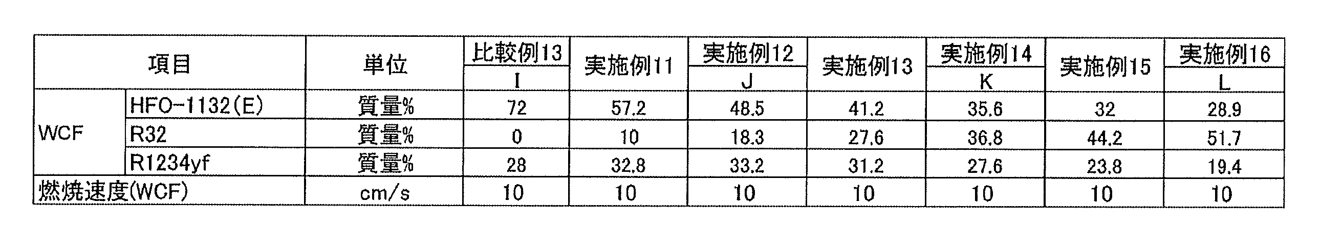
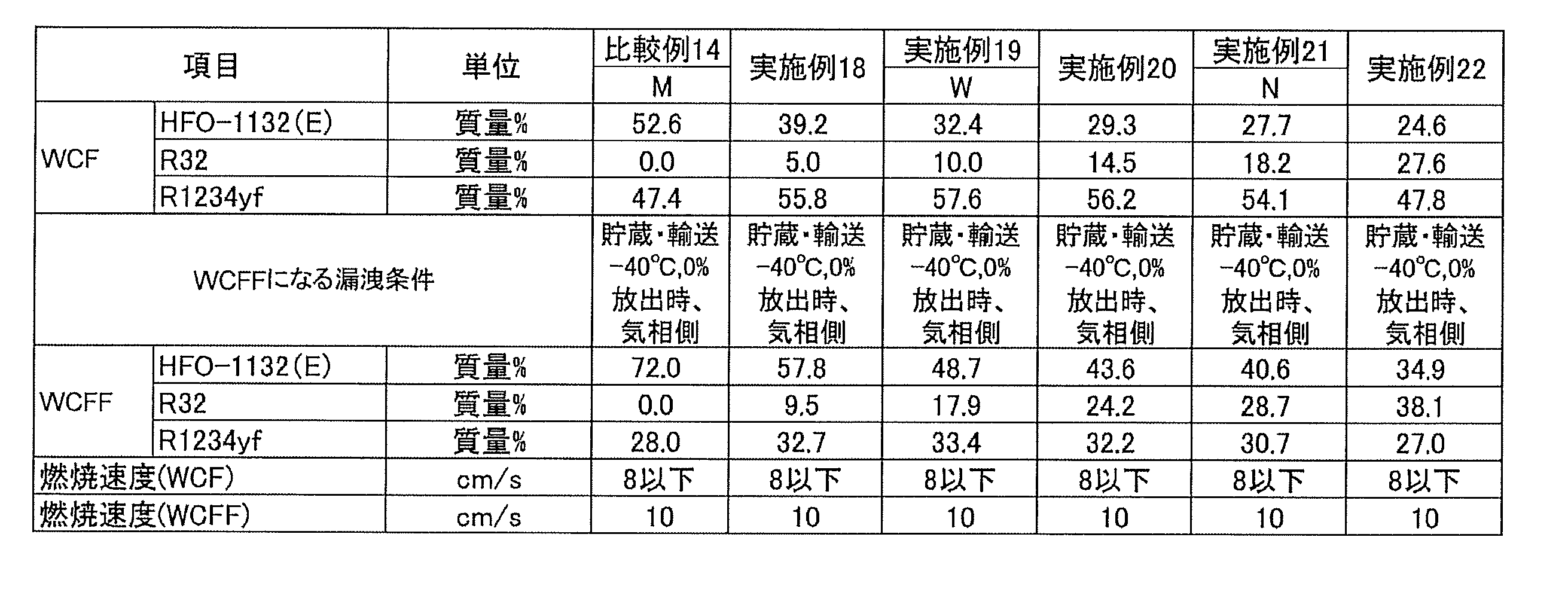
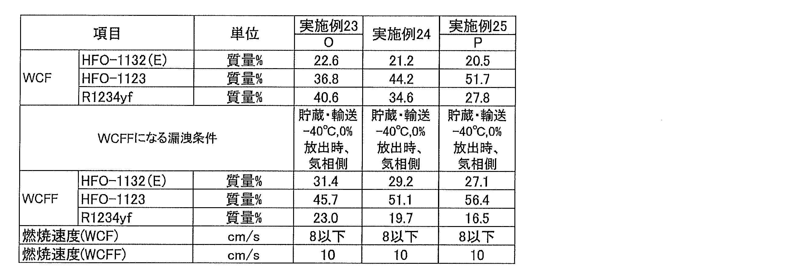
これらの結果から、HFO-1132(E)、R32及びR1234yfの、これらの総和を基準とする質量%をそれぞれx、y及びzとするとき、HFO-1132(E)、R32及びR1234yfの総和が100質量%となる図14の3成分組成図において、座標(x,y,z)が、点I、点J、点K及び点Lをそれぞれ結ぶ線分上又は該線分よりも下側にある場合、WCF微燃となることが判る。
From these results, assuming that the mass% of HFO-1132 (E), R32 and R1234yf based on the total of these is x, y and z, respectively, the sum of HFO-1132 (E), R32 and R1234yf is In the three-component composition diagram of FIG. 14 where 100% by mass is obtained, coordinates (x, y, z) are on or below the line segment connecting point I, point J, point K and point L, respectively. In some cases, it can be seen that WCF is a slight burn.
また、これらの結果から、図14の3成分組成図において、上記座標(x,y,z)が、点M、点M’、点W、点J、点N及び点Pをそれぞれ結ぶ線分上又は該線分よりも下側にある場合、ASHRAE微燃となることが判る。
In addition, from these results, in the three-component composition diagram of FIG. 14, the coordinates (x, y, z) indicate line segments connecting point M, point M ′, point W, point J, point N, and point P, respectively. When it is above or below the line segment, it can be seen that ASHRAE slight burn occurs.
HFO-1132(E)、R32及びR1234yfを、これらの総和を基準として、表116~144にそれぞれ示した質量%で混合した混合冷媒を調製した。表116~144の各混合冷媒について、R410を基準とする成績係数[Coefficient of Performance(COP)]比及び冷凍能力比をそれぞれ求めた。計算条件は以下の通りとした。
A mixed refrigerant was prepared by mixing HFO-1132 (E), R32 and R1234yf in the% by mass shown in Tables 116 to 144, respectively, based on their total sum. For each of the mixed refrigerants in Tables 116 to 144, the coefficient of performance (coefficient of performance (COP)) ratio based on R410 and the refrigeration capacity ratio were determined. The calculation conditions were as follows.
蒸発温度:5℃
凝縮温度:45℃
過熱度:5K
過冷却度;5K
圧縮機効率70%
これらの値を、各混合冷媒についてのGWPと合わせて表116~144に示す。 Evaporation temperature: 5 ° C
Condensing temperature: 45 ° C
Superheat: 5K
Degree of supercooling; 5K
Compressor efficiency 70%
These values are shown in Tables 116-144, together with the GWP for each mixed refrigerant.
凝縮温度:45℃
過熱度:5K
過冷却度;5K
圧縮機効率70%
これらの値を、各混合冷媒についてのGWPと合わせて表116~144に示す。 Evaporation temperature: 5 ° C
Condensing temperature: 45 ° C
Superheat: 5K
Degree of supercooling; 5K
These values are shown in Tables 116-144, together with the GWP for each mixed refrigerant.

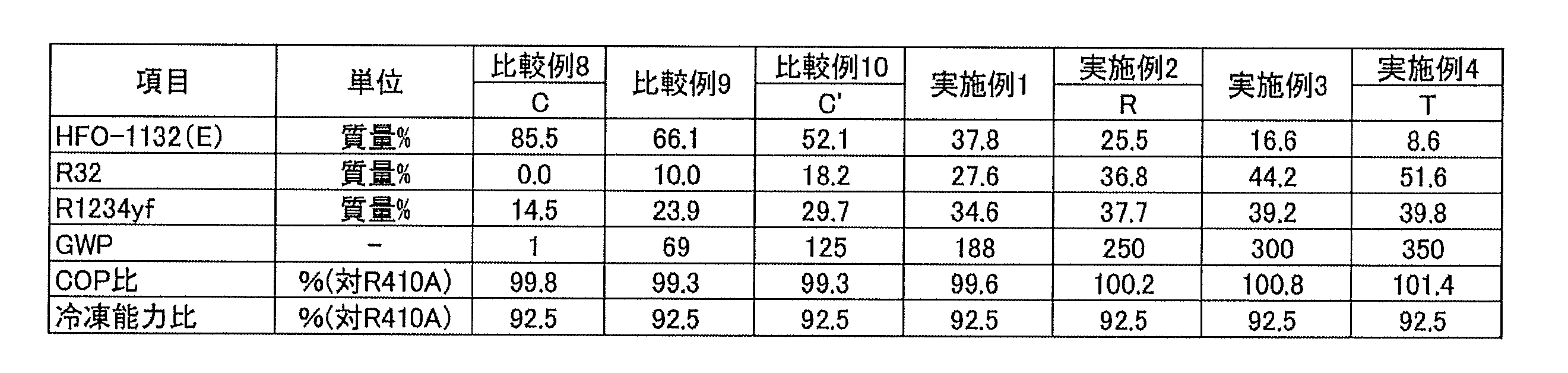


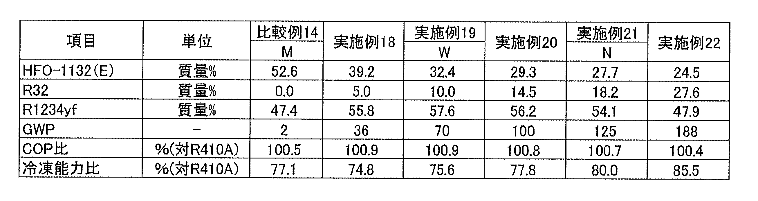

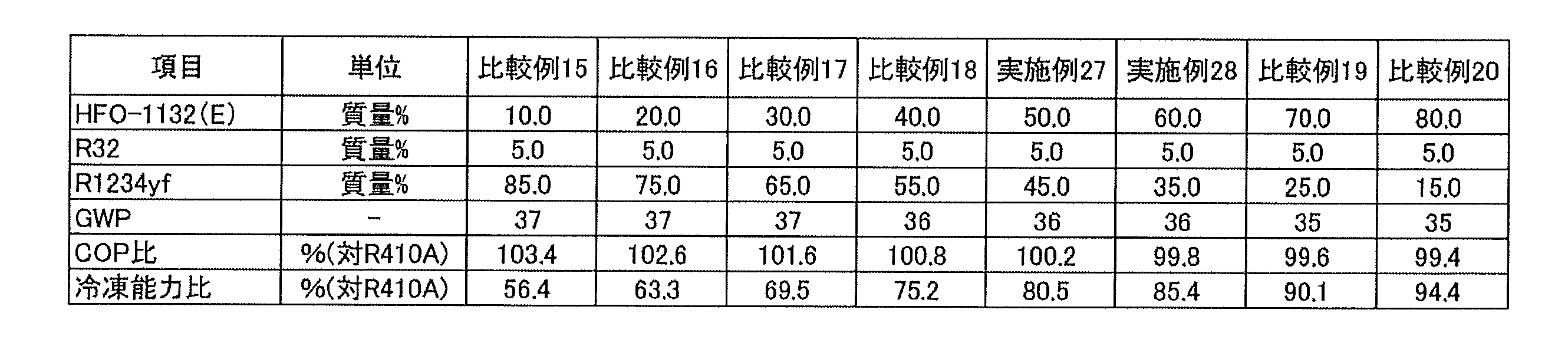


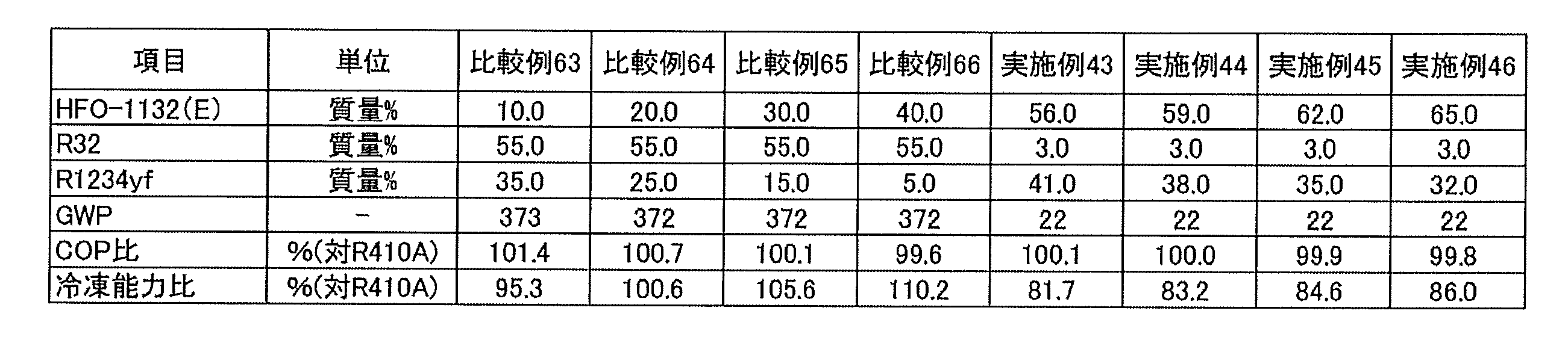
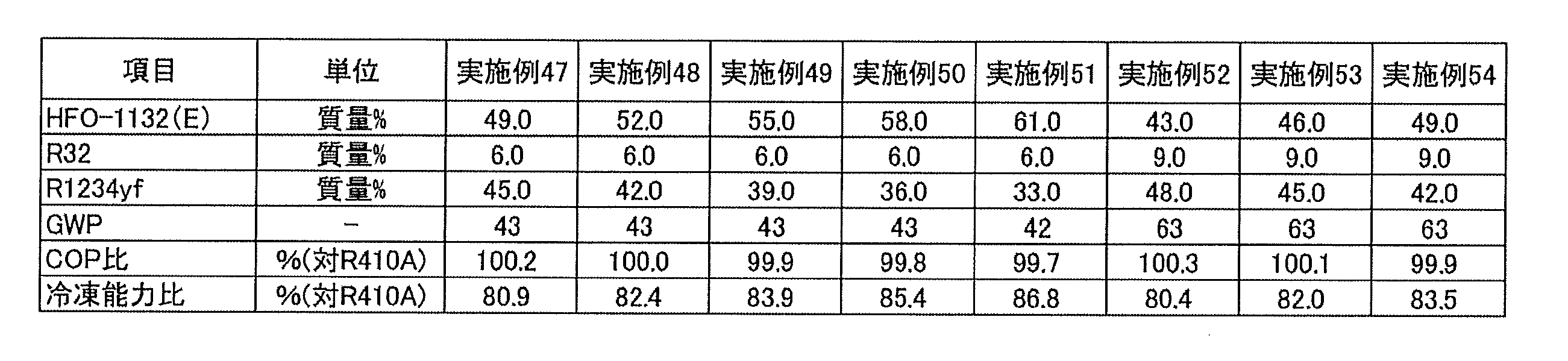


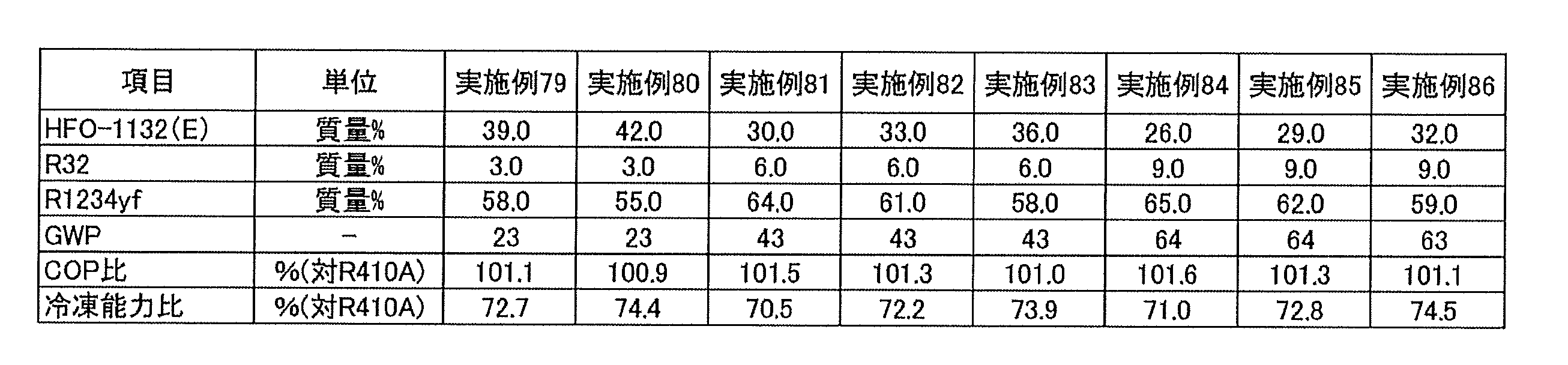
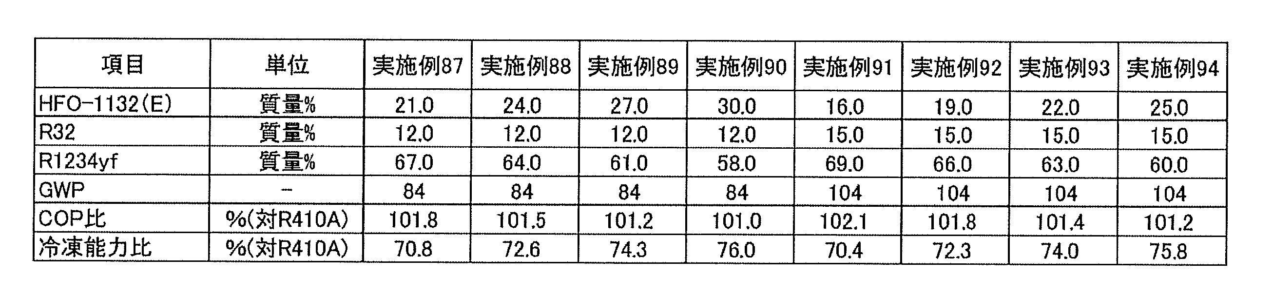


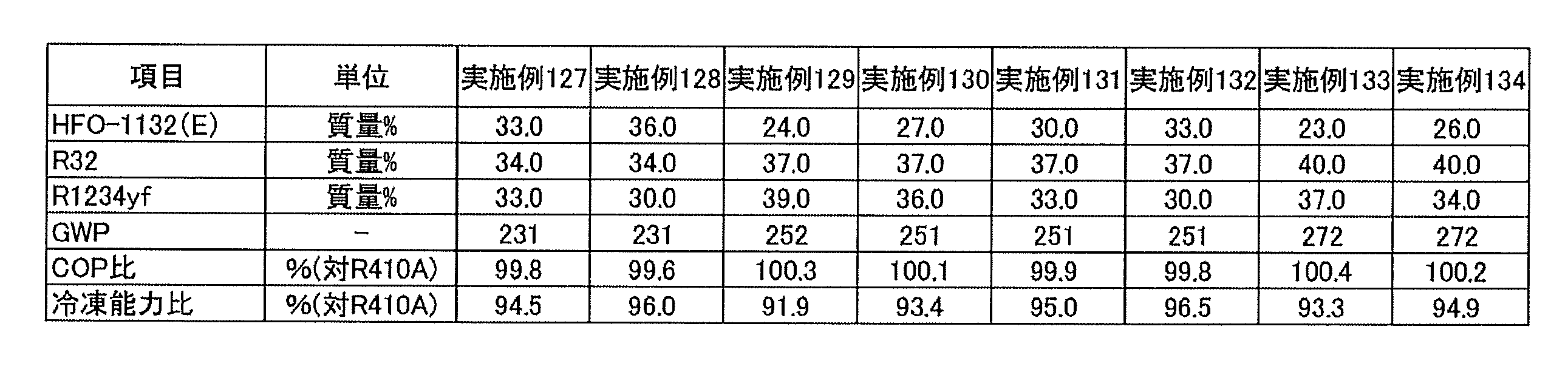

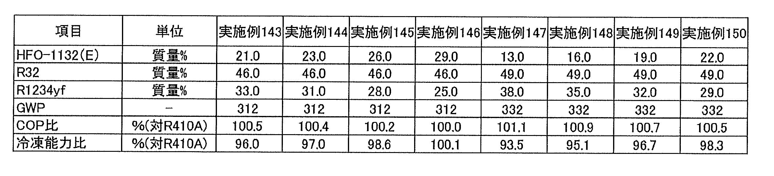

これらの結果から、本開示の冷媒Dは、HFO-1132(E)、R32及びR1234yfの、これらの総和を基準とする質量%をそれぞれx、y及びzとするとき、HFO-1132(E)、R32及びR1234yfの総和が100質量%となる3成分組成図において、座標(x,y,z)が、
点I(72.0, 0.0, 28.0)、
点J(48.5, 18.3, 33.2)、
点N(27.7, 18.2, 54.1)及び
点E(58.3, 0.0, 41.7)
の4点をそれぞれ結ぶ線分IJ、JN、NE、及びEIで囲まれる図形の範囲内又は前記線分上にあり(ただし、線分EI上にある点は除く)、
前記線分IJは、
座標(0.0236y2-1.7616y+72.0, y, -0.0236y2+0.7616y+28.0)
で表わされ、
前記線分NEは、
座標(0.012y2-1.9003y+58.3, y, -0.012y2+0.9003y+41.7)
で表わされ、かつ
前記線分JN及びEIが直線である場合、R410Aを基準とする冷凍能力比が80%以上となり、GWPが125以下となり、かつWCF微燃となることが判る。 From these results, it is assumed that the refrigerant D of the present disclosure is HFO-1132 (E), where x, y and z represent mass% of HFO-1132 (E), R32 and R1234yf based on their total sum, respectively. In the three-component composition diagram in which the sum of R32 and R1234yf is 100% by mass, the coordinates (x, y, z) are
Point I (72.0, 0.0, 28.0),
Point J (48.5, 18.3, 33.2),
Point N (27.7, 18.2, 54.1) and point E (58.3, 0.0, 41.7)
In the range of the figure enclosed by the line segments IJ, JN, NE, and EI connecting the four points of the above, or on the line segment (except for the points on the line segment EI),
The line segment IJ is
Coordinates (0.0236y 2 -1.7616y +72.0, y, -0.0236y 2 + 0.7616y +28.0)
Represented by
The line segment NE is
Coordinates (0.012y 2 -1.9003y + 58.3, y, -0.012y 2 + 0.9003y + 41.7)
In the case where the line segments JN and EI are straight lines, it can be seen that the refrigerating capacity ratio based on R410A is 80% or more, the GWP is 125 or less, and the WCF is slightly incombustible.
また、本開示の冷媒Dは、HFO-1132(E)、R32及びR1234yfの、これらの総和を基準とする質量%をそれぞれx、y及びzとするとき、HFO-1132(E)、R32及びR1234yfの総和が100質量%となる3成分組成図において、座標(x,y,z)が、
点M(52.6, 0.0, 47.4)、
点M’(39.2, 5.0, 55.8)、
点N(27.7, 18.2, 54.1)、
点V(11.0, 18.1, 70.9)及び
点G(39.6, 0.0, 60.4)
の5点をそれぞれ結ぶ線分MM’、M’N、NV、VG、及びGMで囲まれる図形の範囲内又は前記線分上にあり(ただし、線分GM上にある点は除く)、
前記線分MM’は、
座標(x, 0.132x2-3.34x+52.6, -0.132x2+2.34x+47.4)
で表わされ、
前記線分M’Nは、
座標(x, 0.0313x2-1.4551x+43.824, -0.0313x2+0.4551x+56.176)
で表わされ、
前記線分VGは、
座標(0.0123y2-1.8033y+39.6, y, -0.0123y2+0.8033y+60.4)
で表わされ、かつ
前記線分NV及びGMが直線である場合、R410Aを基準とする冷凍能力比が70%以上となり、GWPが125以下となり、かつASHRAE微燃となることが判る。 Further, the refrigerant D of the present disclosure is HFO-1132 (E), R32 and R32 when the mass% of HFO-1132 (E), R32 and R1234yf based on the total of these is respectively x, y and z. In the three-component composition diagram in which the sum of R1234yf is 100% by mass, coordinates (x, y, z) are
Point M (52.6, 0.0, 47.4),
Point M '(39.2, 5.0, 55.8),
Point N (27.7, 18.2, 54.1),
Point V (11.0, 18.1, 70.9) and Point G (39.6, 0.0, 60.4)
Within the range of the figure enclosed by the line segments MM ', M'N, NV, VG, and GM connecting the five points of the above, or on the line segment (except for the points on the line segment GM),
The line segment MM 'is
Coordinates (x, 0.132x 2 -3.34x + 52.6, -0.132x 2 + 2.34x + 47.4)
Represented by
The line segment M'N is
Coordinates (x, 0.0313x 2 -1.4551x + 43.824, -0.0313x 2 + 0.4551x + 56. 176)
Represented by
The line segment VG is
Coordinates (0.0123y 2 -1.8033y + 39.6, y, -0.0123y 2 + 0.8033y + 60.4)
It can be seen that when the line segments NV and GM are straight, the refrigeration capacity ratio based on R410A is 70% or more, the GWP is 125 or less, and ASHRAE slight burn is achieved.
さらに、本開示の冷媒Dは、HFO-1132(E)、R32及びR1234yfの、これらの総和を基準とする質量%をそれぞれx、y及びzとするとき、HFO-1132(E)、R32及びR1234yfの総和が100質量%となる3成分組成図において、座標(x,y,z)が、
点O(22.6, 36.8, 40.6)、
点N(27.7, 18.2, 54.1)及び
点U(3.9, 36.7, 59.4)
の3点をそれぞれ結ぶ線分ON、NU及びUOで囲まれる図形の範囲内又は前記線分上にあり、
前記線分ONは、
座標(0.0072y2-0.6701y+37.512, y, -0.0072y2-0.3299y+62.488)
で表わされ、
前記線分NUは、
座標(0.0083y2-1.7403y+56.635, y, -0.0083y2+0.7403y+43.365)
で表わされ、かつ
前記線分UOが直線である場合、R410Aを基準とする冷凍能力比が80%以上となり、GWPが250以下となり、かつASHRAE微燃となることが判る。 Furthermore, the refrigerant D of the present disclosure is HFO-1132 (E), R32 and R32, where the mass% of HFO-1132 (E), R32 and R1234yf based on the total of these is respectively x, y and z. In the three-component composition diagram in which the sum of R1234yf is 100% by mass, coordinates (x, y, z) are
Point O (22.6, 36.8, 40.6),
Point N (27.7, 18.2, 54.1) and point U (3.9, 36.7, 59.4)
Within the range of the figure bounded by the line segments ON, NU and UO respectively connecting the three points of
The line segment ON is
Coordinates (0.0072y 2 -0.6701y + 37.512, y , -0.0072y 2 -0.3299y + 62.488)
Represented by
The line segment NU is
Coordinates (0.0083y 2 -1.7403y +56.635, y, -0.0083y 2 + 0.7403y +43.365)
It can be seen that when the line segment UO is a straight line, the refrigeration capacity ratio based on R410A is 80% or more, the GWP is 250 or less, and ASHRAE slight burn is achieved.
また、本開示の冷媒Dは、HFO-1132(E)、R32及びR1234yfの、これらの総和を基準とする質量%をそれぞれx、y及びzとするとき、HFO-1132(E)、R32及びR1234yfの総和が100質量%となる3成分組成図において、座標(x,y,z)が、
点Q(44.6, 23.0, 32.4)、
点R(25.5, 36.8, 37.7)、
点T(8.6, 51.6, 39.8)、
点L(28.9, 51.7, 19.4)及び
点K(35.6, 36.8, 27.6)
の5点をそれぞれ結ぶ線分QR、RT、TL、LK及びKQで囲まれる図形の範囲内又は前記線分上にあり、
前記線分QRは、
座標(0.0099y2-1.975y+84.765, y, -0.0099y2+0.975y+15.235)
で表わされ、
前記線分RTは、
座標(0.082y2-1.8683y+83.126, y, -0.082y2+0.8683y+16.874)
で表わされ、
前記線分LKは、
座標(0.0049y2-0.8842y+61.488, y, -0.0049y2-0.1158y+38.512)
で表わされ、
前記線分KQは、
座標(0.0095y2-1.2222y+67.676, y, -0.0095y2+0.2222y+32.324)
で表わされ、かつ
前記線分TLが直線である場合、R410Aを基準とする冷凍能力比が92.5%以上となり、GWPが350以下となり、かつWCF微燃となることが判る。 Further, the refrigerant D of the present disclosure is HFO-1132 (E), R32 and R32 when the mass% of HFO-1132 (E), R32 and R1234yf based on the total of these is respectively x, y and z. In the three-component composition diagram in which the sum of R1234yf is 100% by mass, coordinates (x, y, z) are
Point Q (44.6, 23.0, 32.4),
Point R (25.5, 36.8, 37.7),
Point T (8.6, 51.6, 39.8),
Point L (28.9, 51.7, 19.4) and Point K (35.6, 36.8, 27.6)
Within the range of the figure enclosed by the line segments QR, RT, TL, LK and KQ connecting the five points of
The line segment QR is
Coordinates (0.0099 y 2 -1. 975 y + 84. 765, y, -0.00 99 y 2 + 0.975 y + 15.235)
Represented by
The line segment RT is
Coordinates (0.082y 2 -1.8683y + 83.126, y, -0.082y 2 + 0.8683y + 16.874)
Represented by
The line segment LK is
Coordinates (0.0049y 2 -0.8842y + 61.488, y, -0.0049y 2 -0.1158y + 38.512)
Represented by
The line segment KQ is
Coordinates (0.0095y 2 -1.2222y + 67.676, y, -0.0095y 2 + 0.2222y + 32.324)
In the case where the line segment TL is a straight line, it can be seen that the refrigerating capacity ratio based on R410A is 92.5% or more, the GWP is 350 or less, and the WCF is slightly combustible.
さらに、本開示の冷媒Dは、HFO-1132(E)、R32及びR1234yfの、これらの総和を基準とする質量%をそれぞれx、y及びzとするとき、HFO-1132(E)、R32及びR1234yfの総和が100質量%となる3成分組成図において、座標(x,y,z)が、
点P(20.5, 51.7, 27.8)、
点S(21.9, 39.7, 38.4)及び
点T(8.6, 51.6, 39.8)
の3点をそれぞれ結ぶ線分PS、ST及びTPで囲まれる図形の範囲内又は前記線分上にあり、
前記線分PSは、
座標(0.0064y2-0.7103y+40.1, y, -0.0064y2-0.2897y+59.9)
で表わされ、
前記線分STは、
座標(0.082y2-1.8683y+83.126, y, -0.082y2+0.8683y+16.874)
で表わされ、かつ
前記線分TPが直線である場合、R410Aを基準とする冷凍能力比が92.5%以上となり、GWPが350以下となり、かつASHRAE微燃となることが判る。 Furthermore, the refrigerant D of the present disclosure is HFO-1132 (E), R32 and R32, where the mass% of HFO-1132 (E), R32 and R1234yf based on the total of these is respectively x, y and z. In the three-component composition diagram in which the sum of R1234yf is 100% by mass, coordinates (x, y, z) are
Point P (20.5, 51.7, 27.8),
Point S (21.9, 39.7, 38.4) and point T (8.6, 51.6, 39.8)
Within the range of the figure bounded by the line segments PS, ST, and TP connecting the three points of
The line segment PS is
Coordinates (0.0064y 2 -0.7103y + 40.1, y, -0.0064y 2 -0.2897y + 59.9)
Represented by
The line segment ST is
Coordinates (0.082y 2 -1.8683y + 83.126, y, -0.082y 2 + 0.8683y + 16.874)
When the line segment TP is a straight line, it can be seen that the refrigeration capacity ratio based on R410A is 92.5% or more, the GWP is 350 or less, and ASHRAE slight burn is achieved.
(5-5)冷媒E
本開示の冷媒Eは、トランス-1,2-ジフルオロエチレン(HFO-1132(E))、トリフルオロエチレン(HFO-1123)及びジフルオロメタン(R32)を含む混合冷媒である。 (5-5) Refrigerant E
The refrigerant E of the present disclosure is a mixed refrigerant containing trans-1,2-difluoroethylene (HFO-1132 (E)), trifluoroethylene (HFO-1123) and difluoromethane (R32).
本開示の冷媒Eは、トランス-1,2-ジフルオロエチレン(HFO-1132(E))、トリフルオロエチレン(HFO-1123)及びジフルオロメタン(R32)を含む混合冷媒である。 (5-5) Refrigerant E
The refrigerant E of the present disclosure is a mixed refrigerant containing trans-1,2-difluoroethylene (HFO-1132 (E)), trifluoroethylene (HFO-1123) and difluoromethane (R32).
本開示の冷媒Eは、R410Aと同等の成績係数を有し、かつGWPが十分に小さい、という、R410A代替冷媒として望ましい諸特性を有する。
The refrigerant E of the present disclosure has desirable characteristics as an R410A alternative refrigerant, having a coefficient of performance equivalent to that of R410A, and a sufficiently small GWP.
本開示の冷媒Eは、HFO-1132(E)、HFO-1123及びR32の、これらの総和を基準とする質量%をそれぞれx、y及びzとするとき、HFO-1132(E)、HFO-1123及びR32の総和が100質量%となる3成分組成図において、座標(x,y,z)が、
点I(72.0, 28,0, 0.0)
点K(48.4, 33.2, 18.4)
点B’(0.0, 81.6, 18.4)
点H(0.0, 84.2, 15.8)
点R(23.1, 67.4, 9.5)及び
点G(38.5, 61.5, 0.0)
の6点をそれぞれ結ぶ線分IK、KB’、B’H、HR、RG及びGIで囲まれる図形の範囲内又は前記線分上にあり(ただし、線分B’H及びGI上の点を除く)、
前記線分IKは、
座標(0.025z2-1.7429z+72.00, -0.025z2+0.7429z+28.0, z)
で表わされ、
前記線分HRは、
座標(-0.3123z2+4.234z+11.06, 0.3123z2-5.234z+88.94, z)
で表わされ、
前記線分RGは、
座標(-0.0491z2-1.1544z+38.5, 0.0491z2+0.1544z+61.5, z)
で表わされ、かつ
前記線分KB’及びGIが直線であるものであれば好ましい。本開示の冷媒は、上記要件が満たされる場合、WCF微燃であり、R410Aを基準とするCOP比が93%以上となり、かつGWPが125以下となる。 The refrigerant E of the present disclosure is HFO-1132 (E), HFO-, where the mass% of HFO-1132 (E), HFO-1123 and R32 based on the total of these is respectively x, y and z. In the three-component composition diagram in which the sum of 1123 and R32 is 100% by mass, coordinates (x, y, z) are
Point I (72.0, 28, 0, 0.0)
Point K (48.4, 33.2, 18.4)
Point B '(0.0, 81.6, 18.4)
Point H (0.0, 84.2, 15.8)
Point R (23.1, 67.4, 9.5) and Point G (38.5, 61.5, 0.0)
Within the range of the figure enclosed by the line segments IK, KB ', B'H, HR, RG and GI connecting the six points of except),
The line segment IK is
Coordinates (0.025z 2 -1.7429z + 72.00, -0.025z 2 + 0.7429z + 28.0, z)
Represented by
The line segment HR is
Coordinates (-0.3123z 2 + 4.234z + 11.06, 0.3123z 2 -5.234z + 88.94, z)
Represented by
The line segment RG is
Coordinates (−0.0491z 2 -1.1544z + 38.5, 0.0491z 2 + 0.1544z + 61.5, z)
It is preferable that the line segment KB ′ and GI be straight lines. When the above requirements are satisfied, the refrigerant of the present disclosure is a WCF slight burn, the COP ratio based on R410A is 93% or more, and the GWP is 125 or less.
本開示の冷媒Eは、HFO-1132(E)、HFO-1123及びR32の、これらの総和を基準とする質量%をそれぞれx、y及びzとするとき、HFO-1132(E)、HFO-1123及びR32の総和が100質量%となる3成分組成図において、座標(x,y,z)が、
点I(72.0, 28,0, 0.0)
点J(57.7, 32.8, 9.5)
点R(23.1, 67.4, 9.5)及び
点G(38.5, 61.5, 0.0)
の4点をそれぞれ結ぶ線分IJ、JR、RG及びGIで囲まれる図形の範囲内又は前記線分上にあり(ただし、線分GI上の点を除く)、
前記線分IJは、
座標(0.025z2-1.7429z+72.0, -0.025z2+0.7429z+28.0, z)
で表わされ、かつ
前記線分RGは、
座標(-0.0491z2-1.1544z+38.5, 0.0491z2+0.1544z+61.5, z)
で表わされ、
前記線分JR及びGIが直線であるものであれば好ましい。本開示の冷媒は、上記要件が満たされる場合、WCF微燃であり、R410Aを基準とするCOP比が93%以上となり、かつGWPが125以下となる。 The refrigerant E of the present disclosure is HFO-1132 (E), HFO-, where the mass% of HFO-1132 (E), HFO-1123 and R32 based on the total of these is respectively x, y and z. In the three-component composition diagram in which the sum of 1123 and R32 is 100% by mass, coordinates (x, y, z) are
Point I (72.0, 28, 0, 0.0)
Point J (57.7, 32.8, 9.5)
Point R (23.1, 67.4, 9.5) and Point G (38.5, 61.5, 0.0)
Within the range of the figure bounded by the line segments IJ, JR, RG, and GI connecting the four points of
The line segment IJ is
Coordinates (0.025z 2 -1.7429z + 72.0, -0.025z 2 + 0.7429z + 28.0, z)
And the line segment RG is
Coordinates (−0.0491z 2 -1.1544z + 38.5, 0.0491z 2 + 0.1544z + 61.5, z)
Represented by
It is preferable that the line segments JR and GI be straight lines. When the above requirements are satisfied, the refrigerant of the present disclosure is a WCF slight burn, the COP ratio based on R410A is 93% or more, and the GWP is 125 or less.
本開示の冷媒Eは、HFO-1132(E)、HFO-1123及びR32の、これらの総和を基準とする質量%をそれぞれx、y及びzとするとき、HFO-1132(E)、HFO-1123及びR32の総和が100質量%となる3成分組成図において、座標(x,y,z)が、
点M(47.1, 52.9, 0.0)
点P(31.8, 49.8, 18.4)
点B’(0.0, 81.6, 18.4)
点H(0.0, 84.2, 15.8)
点R(23.1, 67.4, 9.5)及び
点G(38.5, 61.5, 0.0)
の6点をそれぞれ結ぶ線分MP、PB’、B’H、HR、RG及びGMで囲まれる図形の範囲内又は前記線分上にあり(ただし、線分B’H及びGM上の点を除く)、
前記線分MPは、
座標(0.0083z2-0.984z+47.1,-0.0083z2-0.016z+52.9, z)
で表わされ、
前記線分HRは、
座標(-0.3123z2+4.234z+11.06, 0.3123z2-5.234z+88.94, z)
で表わされ、
前記線分RGは、
座標(-0.0491z2-1.1544z+38.5, 0.0491z2+0.1544z+61.5, z)
で表わされ、かつ
前記線分PB’及びGMが直線であるものであれば好ましい。本開示の冷媒は、上記要件が満たされる場合、ASHRAE微燃であり、R410Aを基準とするCOP比が93%以上となり、かつGWPが125以下となる。 The refrigerant E of the present disclosure is HFO-1132 (E), HFO-, where the mass% of HFO-1132 (E), HFO-1123 and R32 based on the total of these is respectively x, y and z. In the three-component composition diagram in which the sum of 1123 and R32 is 100% by mass, coordinates (x, y, z) are
Point M (47.1, 52.9, 0.0)
Point P (31.8, 49.8, 18.4)
Point B '(0.0, 81.6, 18.4)
Point H (0.0, 84.2, 15.8)
Point R (23.1, 67.4, 9.5) and Point G (38.5, 61.5, 0.0)
Within the range of the figure enclosed by the line segments MP, PB ', B'H, HR, RG and GM connecting the six points of except),
The line segment MP is
Coordinates (0.0083z 2 -0.984z + 47.1, -0.0083z 2 -0.016z + 52.9, z)
Represented by
The line segment HR is
Coordinates (-0.3123z 2 + 4.234z + 11.06, 0.3123z 2 -5.234z + 88.94, z)
Represented by
The line segment RG is
Coordinates (−0.0491z 2 -1.1544z + 38.5, 0.0491z 2 + 0.1544z + 61.5, z)
It is preferable that the line segment PB 'and GM be straight. The refrigerant of the present disclosure is ASHRAE slight burn when the above requirements are satisfied, and the COP ratio based on R410A is 93% or more, and the GWP is 125 or less.
本開示の冷媒Eは、HFO-1132(E)、HFO-1123及びR32の、これらの総和を基準とする質量%をそれぞれx、y及びzとするとき、HFO-1132(E)、HFO-1123及びR32の総和が100質量%となる3成分組成図において、座標(x,y,z)が、
点M(47.1, 52.9, 0.0)
点N(38.5, 52.1, 9.5)
点R(23.1, 67.4, 9.5)及び
点G(38.5, 61.5, 0.0)
の4点をそれぞれ結ぶ線分MN、NR、RG及びGMで囲まれる図形の範囲内又は前記線分上にあり(ただし、線分GM上の点を除く)、
前記線分MNは、
座標(0.0083z2-0.984z+47.1,-0.0083z2-0.016z+52.9, z)
で表わされ、かつ
前記線分RGは、
座標(-0.0491z2-1.1544z+38.5, 0.0491z2+0.1544z+61.5, z)
で表わされ、
前記線分JR及びGIが直線であるものであれば好ましい。本開示の冷媒は、上記要件が満たされる場合、ASHRAE微燃であり、R410Aを基準とするCOP比が93%以上となり、かつGWPが65以下となる。 The refrigerant E of the present disclosure is HFO-1132 (E), HFO-, where the mass% of HFO-1132 (E), HFO-1123 and R32 based on the total of these is respectively x, y and z. In the three-component composition diagram in which the sum of 1123 and R32 is 100% by mass, coordinates (x, y, z) are
Point M (47.1, 52.9, 0.0)
Point N (38.5, 52.1, 9.5)
Point R (23.1, 67.4, 9.5) and Point G (38.5, 61.5, 0.0)
Within the range of the figure bounded by the line segments MN, NR, RG and GM connecting the four points of the above, respectively (but excluding the point on the line segment GM),
The line segment MN is
Coordinates (0.0083z 2 -0.984z + 47.1, -0.0083z 2 -0.016z + 52.9, z)
And the line segment RG is
Coordinates (−0.0491z 2 -1.1544z + 38.5, 0.0491z 2 + 0.1544z + 61.5, z)
Represented by
It is preferable that the line segments JR and GI be straight lines. The refrigerant of the present disclosure is ASHRAE slight-combustible when the above requirements are satisfied, and the COP ratio based on R410A is 93% or more, and the GWP is 65 or less.
本開示の冷媒Eは、HFO-1132(E)、HFO-1123及びR32の、これらの総和を基準とする質量%をそれぞれx、y及びzとするとき、HFO-1132(E)、HFO-1123及びR32の総和が100質量%となる3成分組成図において、座標(x,y,z)が、
点P(31.8, 49.8, 18.4)
点S(25.4, 56.2, 18.4)及び
点T(34.8, 51.0, 14.2)
の3点をそれぞれ結ぶ線分PS、ST及びTPで囲まれる図形の範囲内又は前記線分上にあり、
前記線分STは、
座標(-0.0982z2+0.9622z+40.931, 0.0982z2-1.9622z+59.069, z)
で表わされ、かつ
前記線分TPは、
座標(0.0083z2-0.984z+47.1,-0.0083z2-0.016z+52.9, z)
で表わされ、
前記線分PSが直線であるものであれば好ましい。本開示の冷媒は、上記要件が満たされる場合、ASHRAE微燃であり、R410Aを基準とするCOP比が94.5%以上となり、かつGWPが125以下となる。 The refrigerant E of the present disclosure is HFO-1132 (E), HFO-, where the mass% of HFO-1132 (E), HFO-1123 and R32 based on the total of these is respectively x, y and z. In the three-component composition diagram in which the sum of 1123 and R32 is 100% by mass, coordinates (x, y, z) are
Point P (31.8, 49.8, 18.4)
Point S (25.4, 56.2, 18.4) and Point T (34.8, 51.0, 14.2)
Within the range of the figure bounded by the line segments PS, ST, and TP connecting the three points of
The line segment ST is
Coordinates (-0.0982z 2 + 0.9622z + 40.931, 0.0982z 2 -1.9622z + 59.069, z)
And the line segment TP is
Coordinates (0.0083z 2 -0.984z + 47.1, -0.0083z 2 -0.016z + 52.9, z)
Represented by
It is preferable that the line segment PS be a straight line. The refrigerant of the present disclosure is ASHRAE slight burn when the above requirements are satisfied, and the COP ratio based on R410A is 94.5% or more, and the GWP is 125 or less.
本開示の冷媒Eは、HFO-1132(E)、HFO-1123及びR32の、これらの総和を基準とする質量%をそれぞれx、y及びzとするとき、HFO-1132(E)、HFO-1123及びR32の総和が100質量%となる3成分組成図において、座標(x,y,z)が、
点Q(28.6, 34.4, 37.0)
点B’’(0.0, 63.0, 37.0)
点D(0.0, 67.0, 33.0)及び
点U(28.7, 41.2, 30.1)
の4点をそれぞれ結ぶ線分QB’’、B’’D、DU及びUQで囲まれる図形の範囲内又は前記線分上にあり(ただし、線分B’’D上の点を除く)、
前記線分DUは、
座標(-3.4962z2+210.71z-3146.1, 3.4962z2-211.71z+3246.1, z)で表わされ、かつ
前記線分UQは、
座標(0.0135z2-0.9181z+44.133, -0.0135z2-0.0819z+55.867, z)で表わされ、
前記線分QB’’及びB’’Dが直線であるものであれば好ましい。本開示の冷媒は、上記要件が満たされる場合、ASHRAE微燃であり、R410Aを基準とするCOP比が96%以上となり、かつGWPが250以下となる。 The refrigerant E of the present disclosure is HFO-1132 (E), HFO-, where the mass% of HFO-1132 (E), HFO-1123 and R32 based on the total of these is respectively x, y and z. In the three-component composition diagram in which the sum of 1123 and R32 is 100% by mass, coordinates (x, y, z) are
Point Q (28.6, 34.4, 37.0)
Point B '' (0.0, 63.0, 37.0)
Point D (0.0, 67.0, 33.0) and point U (28.7, 41.2, 30.1)
Within the range of the figure enclosed by the line segments QB ′ ′, B′′D, DU and UQ connecting the four points of (in addition to the points on the line segment B′′D),
The line segment DU is
The coordinates (−3.4962z 2 + 210.71z−3146.1, 3.4962z 2 −211.71z + 3246.1, z) are represented, and the line segment UQ is
Represented by the coordinates (0.0135z 2 -0.9181z + 44.133, -0.0135z 2 -0.0819z + 55.867, z),
It is preferable that the line segments QB ′ ′ and B′′D be straight. The refrigerant of the present disclosure is ASHRAE slight burn when the above requirements are satisfied, and the COP ratio based on R410A is 96% or more, and the GWP is 250 or less.
本開示の冷媒Eは、HFO-1132(E)、HFO-1123及びR32の、これらの総和を基準とする質量%をそれぞれx、y及びzとするとき、HFO-1132(E)、HFO-1123及びR32の総和が100質量%となる3成分組成図において、座標(x,y,z)が、
点O(100.0, 0.0, 0.0)、
点c’(56.7, 43.3, 0.0)、
点d’(52.2, 38.3, 9.5)、
点e’(41.8, 39.8, 18.4)及び
点a’(81.6, 0.0, 18.4)
の5点をそれぞれ結ぶ線分Oc’、c’d’、d’e’、e’a’及びa’Oで囲まれる図形の範囲内又は前記線分c’d’、d’e’及びe’a’上にあり(ただし、点c’及びa’を除く)、
前記線分c’d’は、
座標(-0.0297z2-0.1915z+56.7, 0.0297z2+1.1915z+43.3, z)
で表わされ、
前記線分d’e’は、
座標(-0.0535z2+0.3229z+53.957, 0.0535z2+0.6771z+46.043, z)で表わされ、かつ
前記線分Oc’、e’a’及びa’Oが直線であるものであれば好ましい。本開示の冷媒は、上記要件が満たされる場合、R410Aを基準とするCOP比が92.5%以上となり、かつGWPが125以下となる。 The refrigerant E of the present disclosure is HFO-1132 (E), HFO-, where the mass% of HFO-1132 (E), HFO-1123 and R32 based on the total of these is respectively x, y and z. In the three-component composition diagram in which the sum of 1123 and R32 is 100% by mass, coordinates (x, y, z) are
Point O (100.0, 0.0, 0.0),
Point c '(56.7, 43.3, 0.0),
Point d '(52.2, 38.3, 9.5),
Point e '(41.8, 39.8, 18.4) and point a' (81.6, 0.0, 18.4)
Within the range of the figure enclosed by the line segments Oc ′, c′d ′, d′ e ′, e′a ′ and a′O connecting the five points of the above, or the line segments c′d ′, d′ e ′ and on e'a '(but excluding points c' and a '),
The line segment c'd 'is
Coordinates (-0.0297z 2 -0.1915z + 56.7, 0.0297z 2 + 1.1915z + 43.3, z)
Represented by
The line segment d'e 'is
If the coordinates (−0.0535z 2 + 0.3229z + 53.957, 0.0535z 2 + 0.6771z + 46.043, z) are represented and the line segments Oc ′, e′a ′ and a′O are straight lines Is preferable. The refrigerant of the present disclosure has a COP ratio of 92.5% or more based on R410A and a GWP of 125 or less when the above requirements are satisfied.
本開示の冷媒Eは、HFO-1132(E)、HFO-1123及びR32の、これらの総和を基準とする質量%をそれぞれx、y及びzとするとき、HFO-1132(E)、HFO-1123及びR32の総和が100質量%となる3成分組成図において、座標(x,y,z)が、
点O(100.0, 0.0, 0.0)、
点c(77.7, 22.3, 0.0)、
点d(76.3, 14.2, 9.5)、
点e(72.2, 9.4, 18.4)及び
点a’(81.6, 0.0, 18.4)
の5点をそれぞれ結ぶ線分Oc、cd、de、ea’及びa’Oで囲まれる図形の範囲内又は前記線分cd、de及びea’上にあり(ただし、点c及びa’を除く)、
前記線分cdeは、
座標(-0.017z2+0.0148z+77.684, 0.017z2+0.9852z+22.316, z)で表わされ、かつ
前記線分Oc、ea’及びa’Oが直線であるものであれば好ましい。本開示の冷媒は、上記要件が満たされる場合、R410Aを基準とするCOP比が95%以上となり、かつGWPが125以下となる。 The refrigerant E of the present disclosure is HFO-1132 (E), HFO-, where the mass% of HFO-1132 (E), HFO-1123 and R32 based on the total of these is respectively x, y and z. In the three-component composition diagram in which the sum of 1123 and R32 is 100% by mass, coordinates (x, y, z) are
Point O (100.0, 0.0, 0.0),
Point c (77.7, 22.3, 0.0),
Point d (76.3, 14.2, 9.5),
Point e (72.2, 9.4, 18.4) and point a '(81.6, 0.0, 18.4)
In the range of the figure enclosed by the line segments Oc, cd, de, ea 'and a'O connecting the five points of the above, or on the line segments cd, de and ea' (but excluding the points c and a ' ),
The line segment cde is
It is preferable that the coordinates (−0.017z 2 + 0.0148z + 77.684, 0.017z 2 + 0.9852z +22.316, z) be expressed, and the line segments Oc, ea ′ and a′O be straight lines. The refrigerant of the present disclosure has a COP ratio of 95% or more based on R410A and a GWP of 125 or less when the above requirements are satisfied.
本開示の冷媒Eは、HFO-1132(E)、HFO-1123及びR32の、これらの総和を基準とする質量%をそれぞれx、y及びzとするとき、HFO-1132(E)、HFO-1123及びR32の総和が100質量%となる3成分組成図において、座標(x,y,z)が、
点O(100.0, 0.0, 0.0)、
点c’(56.7, 43.3, 0.0)、
点d’(52.2, 38.3, 9.5)及び
点a(90.5, 0.0, 9.5)
の5点をそれぞれ結ぶ線分Oc’、c’d’、d’a及びaOで囲まれる図形の範囲内又は前記線分c’d’及びd’a上にあり(ただし、点c’及びaを除く)、
前記線分c’d’は、
座標(-0.0297z2-0.1915z+56.7, 0.0297z2+1.1915z+43.3, z)で表わされ、かつ
前記線分Oc’、d’a及びaOが直線であるものであれば好ましい。本開示の冷媒は、上記要件が満たされる場合、R410Aを基準とするCOP比が93.5%以上となり、かつGWPが65以下となる。 The refrigerant E of the present disclosure is HFO-1132 (E), HFO-, where the mass% of HFO-1132 (E), HFO-1123 and R32 based on the total of these is respectively x, y and z. In the three-component composition diagram in which the sum of 1123 and R32 is 100% by mass, coordinates (x, y, z) are
Point O (100.0, 0.0, 0.0),
Point c '(56.7, 43.3, 0.0),
Point d '(52.2, 38.3, 9.5) and point a (90.5, 0.0, 9.5)
Within the range of the figure enclosed by line segments Oc ', c'd', d'a and aO respectively connecting the five points of the above, or on the line segments c'd 'and d'a (provided that the points c' and except a),
The line segment c'd 'is
It is preferable if it is represented by the coordinates (−0.0297z 2 −0.1915z + 56.7, 0.0297z 2 + 1.915z + 43.3, z), and the line segments Oc ′, d′ a and aO are straight lines. The refrigerant of the present disclosure has a COP ratio of 93.5% or more based on R410A and a GWP of 65 or less when the above-mentioned requirements are satisfied.
本開示の冷媒Eは、HFO-1132(E)、HFO-1123及びR32の、これらの総和を基準とする質量%をそれぞれx、y及びzとするとき、HFO-1132(E)、HFO-1123及びR32の総和が100質量%となる3成分組成図において、座標(x,y,z)が、
点O(100.0, 0.0, 0.0)、
点c(77.7, 22.3, 0.0)、
点d(76.3, 14.2, 9.5)、
点a(90.5, 0.0, 9.5)
の5点をそれぞれ結ぶ線分Oc、cd、da及びaOで囲まれる図形の範囲内又は前記線分cd及びda上にあり(ただし、点c及びaを除く)、
前記線分CDは、
座標(-0.017z2+0.0148z+77.684, 0.017z2+0.9852z+22.316, z)で表わされ、かつ
前記線分Oc、da及びaOが直線であるものであれば好ましい。本開示の冷媒は、上記要件が満たされる場合、R410Aを基準とするCOP比が95%以上となり、かつGWPが65以下となる。 The refrigerant E of the present disclosure is HFO-1132 (E), HFO-, where the mass% of HFO-1132 (E), HFO-1123 and R32 based on the total of these is respectively x, y and z. In the three-component composition diagram in which the sum of 1123 and R32 is 100% by mass, coordinates (x, y, z) are
Point O (100.0, 0.0, 0.0),
Point c (77.7, 22.3, 0.0),
Point d (76.3, 14.2, 9.5),
Point a (90.5, 0.0, 9.5)
In the range of the figure enclosed by the line segments Oc, cd, da and aO respectively connecting the five points of (or except the points c and a)
The line segment CD is
It is preferable if it is represented by coordinates (−0.017z 2 + 0.0148z + 77.684, 0.017z 2 + 0.9852z + 22.316, z), and the line segments Oc, da and aO are straight lines. The refrigerant of the present disclosure has a COP ratio of 95% or more based on R410A and a GWP of 65 or less when the above-mentioned requirements are satisfied.
本開示の冷媒Eは、上記の特性や効果を損なわない範囲内で、HFO-1132(E)、HFO-1123及びR32に加えて、さらに他の追加的な冷媒を含有していてもよい。この点で、本開示の冷媒Eが、HFO-1132(E)、HFO-1123及びR32の合計を、冷媒全体に対して99.5質量%以上含むことが好ましく、99.75質量%以上含むことがより好ましく、99.9質量%以上含むことがさらに好ましい。
The refrigerant E of the present disclosure may further contain other additional refrigerants in addition to HFO-1132 (E), HFO-1123, and R32, as long as the above-described properties and effects are not impaired. In this respect, the refrigerant E of the present disclosure preferably contains 99.5% by mass or more, more preferably 99.75% by mass or more, of the total of HFO-1132 (E), HFO-1123 and R32 with respect to the entire refrigerant. It is more preferable to contain 99.9 mass% or more.
追加的な冷媒としては、特に限定されず、幅広く選択できる。混合冷媒は、追加的な冷媒として、一種を単独で含んでいてもよいし、二種以上を含んでいてもよい。
The additional refrigerant is not particularly limited and can be widely selected. The mixed refrigerant may contain one kind alone as an additional refrigerant, or may contain two or more kinds.
(冷媒Eの実施例)
以下に、冷媒Eの実施例を挙げてさらに詳細に説明する。ただし、冷媒Eは、これらの実施例に限定されるものではない。 (Example of refrigerant E)
Below, the Example of the refrigerant | coolant E is mentioned and described in more detail. However, the refrigerant E is not limited to these examples.
以下に、冷媒Eの実施例を挙げてさらに詳細に説明する。ただし、冷媒Eは、これらの実施例に限定されるものではない。 (Example of refrigerant E)
Below, the Example of the refrigerant | coolant E is mentioned and described in more detail. However, the refrigerant E is not limited to these examples.
HFO-1132(E)、HFO-1123及びR32を、これらの総和を基準として、表145及び表146にそれぞれ示した質量%で混合した混合冷媒を調製した。各混合物の組成をWCFとし、ASHRAE34-2013規格に従って装置(Equipment)、貯蔵(Storage)、輸送(Shipping)、漏洩(Leak)及び再充填(Recharge)の条件でNational Institute of Science and Technology (NIST) Standard Reference Data Base Refleak Version 4.0により漏洩シミュレーションを行い、最も燃えやすい分画(fraction)をWCFFとした。
A mixed refrigerant was prepared by mixing HFO-1132 (E), HFO-1123 and R32 in the mass% shown in Table 145 and Table 146, respectively, based on the total of these. The composition of each mixture is WCF, and in accordance with the ASHRAE 34-2013 standard, the condition (Equipment), (Storage), (Shipping), (Shipping), (Leak) and Recharge the National Institute of Science and Technology (NIST) Leakage simulation was performed according to Standard Reference Data Base Refleak Version 4.0, and the most flammable fraction was WCFF.
これらの各混合冷媒について、ANSI/ASHRAE34-2013規格に従い燃焼速度を測定した。WCF組成、及びWCFF組成の燃焼速度が10 cm/s以下となるものはASHRAEの燃焼性分類で「2Lクラス(微燃性)」に相当する。
For each of these mixed refrigerants, the burning rate was measured in accordance with the ANSI / ASHRA 34-2013 standard. The WCF composition and the WCFF composition having a burning rate of 10 cm / s or less correspond to the “2 L class (slight flammability)” in the flammability classification of ASHRAE.
なお、燃焼速度試験は図1に示す装置を用いて、以下の通り行った。まず、使用した混合冷媒は99.5%またはそれ以上の純度とし、真空ゲージ上に空気の痕跡が見られなくなるまで凍結、ポンピング及び解凍のサイクルを繰り返すことにより脱気した。閉鎖法により燃焼速度を測定した。初期温度は周囲温度とした。点火は、試料セルの中心で電極間に電気的スパークを生じさせることにより行った。放電の持続時間は1.0~9.9msとし、点火エネルギーは典型的には約0.1~1.0Jであった。シュリーレン写真を使って炎の広がりを視覚化した。光を通す2つのアクリル窓を備えた円筒形容器(内径:155mm、長さ:198mm)を試料セルとして用い、光源としてはキセノンランプを用いた。炎のシュリーレン画像を高速デジタルビデオカメラで600fpsのフレーミング速度で記録し、PCに保存した。
In addition, the burning rate test was done as follows using the apparatus shown in FIG. First, the mixed refrigerant used was 99.5% or more pure and degassed by repeated cycles of freezing, pumping and thawing until no traces of air were visible on the vacuum gauge. The burning rate was measured by the closure method. The initial temperature was ambient temperature. Ignition was performed by creating an electrical spark between the electrodes at the center of the sample cell. The duration of the discharge was 1.0 to 9.9 ms, and the ignition energy was typically about 0.1 to 1.0 J. The spread of the flame was visualized using Schlieren photographs. A cylindrical container (inner diameter: 155 mm, length: 198 mm) equipped with two acrylic windows for transmitting light was used as a sample cell, and a xenon lamp was used as a light source. Schlieren images of flames were recorded with a high speed digital video camera at a framing rate of 600 fps and stored on a PC.
結果を表145及び表146に示す。
The results are shown in Table 145 and Table 146.
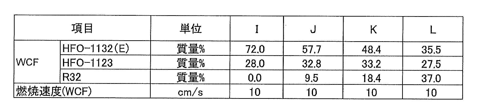
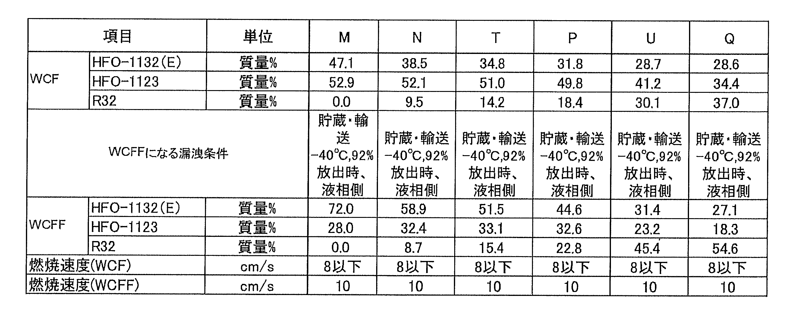
表145の結果から、HFO-1132(E)、HFO-1123及びR32の混合冷媒においては、これらの総和が100質量%となる3成分組成図であって、点(0.0, 100.0, 0.0)及び点(0.0, 0.0, 100.0)を結ぶ線分を底辺とし、点(0.0, 100.0, 0.0)を左側、点(0.0, 0.0, 100.0)を右側とする3成分組成図において、座標(x,y,z)が、
点I(72.0, 28,0, 0.0)
点K(48.4, 33.2, 18.4)及び
点L(35.5, 27.5, 37.0)
の3点をそれぞれ結ぶ線分IK及びKLの上、又は当該線分の下側にあり、
前記線分IKは、
座標(0.025z2-1.7429z+72.00, -0.025z2+0.7429z+28.00, z)で表わされ、かつ
前記線分KLは、
座標(0.0098z2-1.238z+67.852, -0.0098z2+0.238z+32.148, z)で表わされる場合にWCF微燃と判断できることが明らかとなった。 From the results of Table 145, in the case of a mixed refrigerant of HFO-1132 (E), HFO-1123 and R32, it is a three-component composition diagram in which the total sum thereof becomes 100 mass%, and points (0.0, 100.0, 0.0) and In the three-component composition diagram where the line connecting the points (0.0, 0.0, 100.0) is the base and the points (0.0, 100.0, 0.0) are on the left and the points (0.0, 0.0, 100.0) are on the right, the coordinates (x, y , z) but
Point I (72.0, 28, 0, 0.0)
Point K (48.4, 33.2, 18.4) and point L (35.5, 27.5, 37.0)
Above the line segments IK and KL connecting the three points of
The line segment IK is
The coordinates (0.025z 2 -1.7429z + 72.00, -0.025z 2 + 0.7429z + 28.00, z) are represented, and the line segment KL is
Coordinates (0.0098z 2 -1.238z + 67.852, -0.0098z 2 + 0.238z + 32.148, z) revealed that it can be determined that the WCF fine fuel when represented by.
線分IK上の点は、I(72.0, 28,0, 0.0)、J(57.7, 32.8, 9.5)、K(48.4, 33.2, 18.4)の3点から最小二乗法により近似曲線x=0.025z2-1.7429z+72.00を求め、座標(x=0.025z2-1.7429z+72.00, y=100-z-x=-0.00922z2+0.2114z+32.443, z)を求めた。
The point on the line IK is an approximate curve x = 0.025z according to the least squares method from three points I (72.0, 28, 0, 0.0), J (57.7, 32.8, 9.5), and K (48.4, 33.2, 18.4). seeking 2 -1.7429z + 72.00, coordinates (x = 0.025z 2 -1.7429z + 72.00 , y = 100-zx = -0.00922z 2 + 0.2114z + 32.443, z) was determined.
以下同様に線分KL上の点は、K(48.4, 33.2, 18.4)、実施例10(41.1, 31.2, 27.7)、L(35.5, 27.5, 37.0)の3点から最小二乗法により近似曲線を求め、座標を定めた。
Similarly, the points on the line segment KL are approximated curves by the least squares method from three points of K (48.4, 33.2, 18.4), Example 10 (41.1, 31.2, 27.7) and L (35.5, 27.5, 37.0). Determined, determined the coordinates.
表146の結果から、HFO-1132(E)、HFO-1123及びR32の混合冷媒においては、これらの総和が100質量%となる3成分組成図であって、点(0.0, 100.0, 0.0)及び点(0.0, 0.0, 100.0)を結ぶ線分を底辺とし、点(0.0, 100.0, 0.0)を左側、点(0.0, 0.0, 100.0)を右側とする3成分組成図において、座標(x,y,z)が、
点M(47.1, 52.9, 0.0)、
点P(31.8, 49.8, 18.4)及び
点Q(28.6, 34.4, 37.0)
の3点をそれぞれ結ぶ線分MP及びPQの上、又は当該線分の下側にある場合にASHRAE微燃と判断できることが明らかとなった。ただし、前記線分MPは、座標(0.0083z2-0.984z+47.1, -0.0083z2-0.016z+52.9,z)で表わされ、前記線分PQは、座標(0.0135z2-0.9181z+44.133, -0.0135z2-0.0819z+55.867,z)で表わされる。 From the results of Table 146, in the mixed refrigerant of HFO-1132 (E), HFO-1123 and R32, it is a three-component composition diagram in which the total sum thereof becomes 100 mass%, and the points (0.0, 100.0, 0.0) and In the three-component composition diagram where the line connecting the points (0.0, 0.0, 100.0) is the base and the points (0.0, 100.0, 0.0) are on the left and the points (0.0, 0.0, 100.0) are on the right, the coordinates (x, y , z) but
Point M (47.1, 52.9, 0.0),
Point P (31.8, 49.8, 18.4) and point Q (28.6, 34.4, 37.0)
It became clear that it could be judged as ASHRAE slight burn when it was on the line segment MP and PQ connecting the three points of the above, or below the line segment. However, the line segment MP is represented by coordinates (0.0083z 2 -0.984z + 47.1, -0.0083z 2 -0.016z + 52.9, z), and the line segment PQ is represented by coordinates (0.0135z 2 -0.9181z). +44.133, -0.0135z 2 -0.0819z + 55.867, z).
線分MP上の点は、点M,N,Pの3点から最小二乗法により近似曲線を求め、線分PQ上の点は点P,U,Qの3点から最小二乗法により近似曲線を求め、座標を定めた。
The point on the line segment MP obtains an approximate curve from the three points M, N, and P by the least squares method, and the point on the line segment PQ approximates the curve from the three points P, U, and Q by the least squares method The coordinates were determined.
また、R410A(R32=50%/R125=50%)の混合物を含有する組成物のGWPは、IPCC(Intergovernmental Panel on Climate Change)第4次報告書の値に基づいて評価した。HFO-1132(E)のGWPは記載がないが、HFO-1132a(GWP=1以下)、HFO-1123(GWP=0.3, 国際公開第2015/141678号に記載)から、そのGWPを1と想定した。R410A及びHFO-1132(E)とHFO-1123との混合物を含有する組成物の冷凍能力は、National Institute of Science and Technology(NIST) Reference Fluid Thermodynamic and Transport Properties Database(Refprop 9.0)を使い、下記条件で混合冷媒の冷凍サイクル理論計算を実施することにより求めた。これらの各混合冷媒について、R410を基準とするCOP比及び冷凍能力[Refrigeration Capacity(Cooling Capacity又はCapacityと表記されることもある)]比をそれぞれ求めた。計算条件は以下の通りとした。
Moreover, GWP of the composition containing the mixture of R410A (R32 = 50% / R125 = 50%) was evaluated based on the value of the IPCC (Intergovernmental Panel on Climate Change) 4th report. Although GWP of HFO-1132 (E) is not described, HFO-1132a (GWP = 1 or less), HFO-1123 (GWP = 0.3, described in WO 2015/141678), the GWP is assumed to be 1. did. The refrigeration capacity of a composition containing a mixture of R410A and HFO-1132 (E) and HFO-1123 is as follows using the National Institute of Science and Technology (NIST) Reference Fluid Thermodynamic and Transport Properties Database (Refprop 9.0) It calculated | required by implementing the refrigeration cycle theoretical calculation of mixed refrigerant. For each of these mixed refrigerants, a COP ratio based on R410 and a refrigeration capacity [Refrigeration Capacity (sometimes referred to as Cooling Capacity or Capacity)] ratio were respectively determined. The calculation conditions were as follows.
蒸発温度:5℃
凝縮温度:45℃
過熱度:5K
過冷却度;5K
圧縮機効率70%
これらの値を、各混合冷媒についてのGWPと合わせて表147~166に示す。 Evaporation temperature: 5 ° C
Condensing temperature: 45 ° C
Superheat: 5K
Degree of supercooling; 5K
Compressor efficiency 70%
These values are shown in Tables 147-166, together with the GWP for each mixed refrigerant.
凝縮温度:45℃
過熱度:5K
過冷却度;5K
圧縮機効率70%
これらの値を、各混合冷媒についてのGWPと合わせて表147~166に示す。 Evaporation temperature: 5 ° C
Condensing temperature: 45 ° C
Superheat: 5K
Degree of supercooling; 5K
These values are shown in Tables 147-166, together with the GWP for each mixed refrigerant.
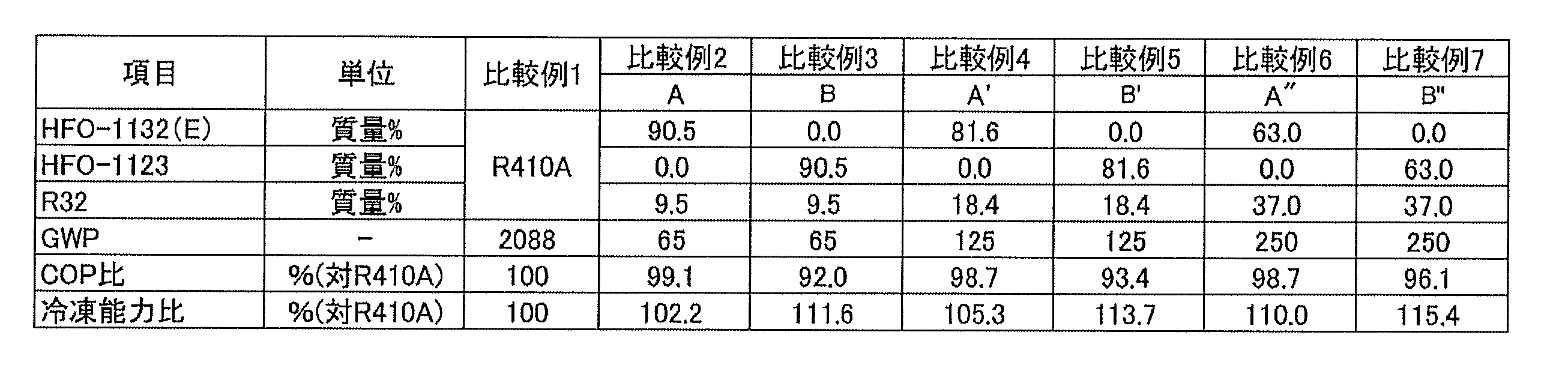
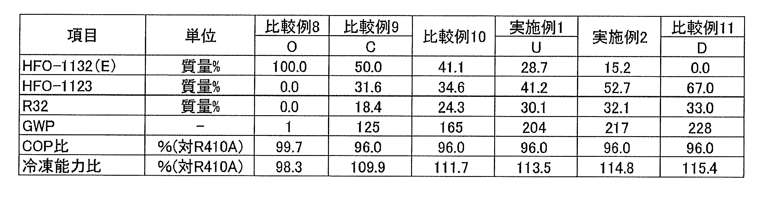


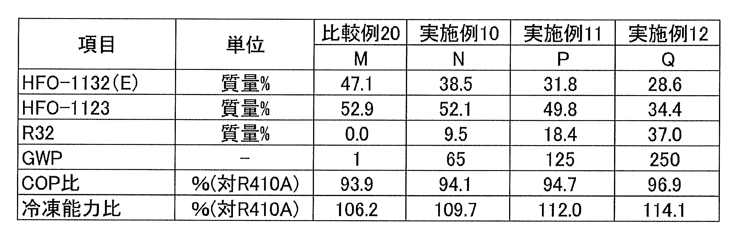
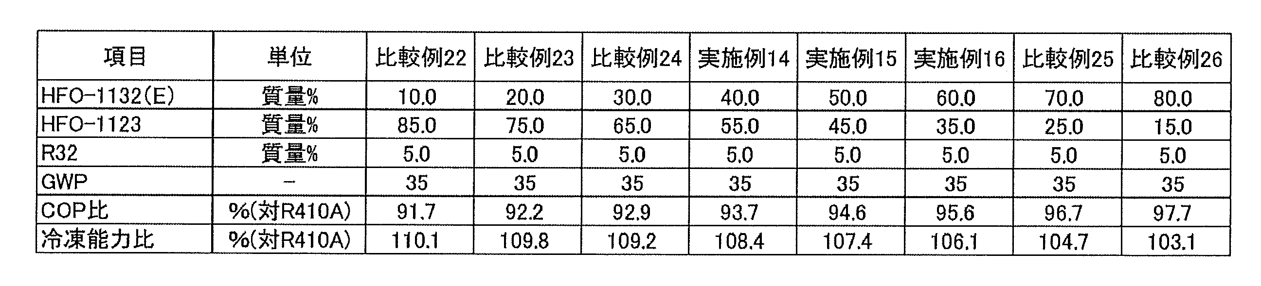
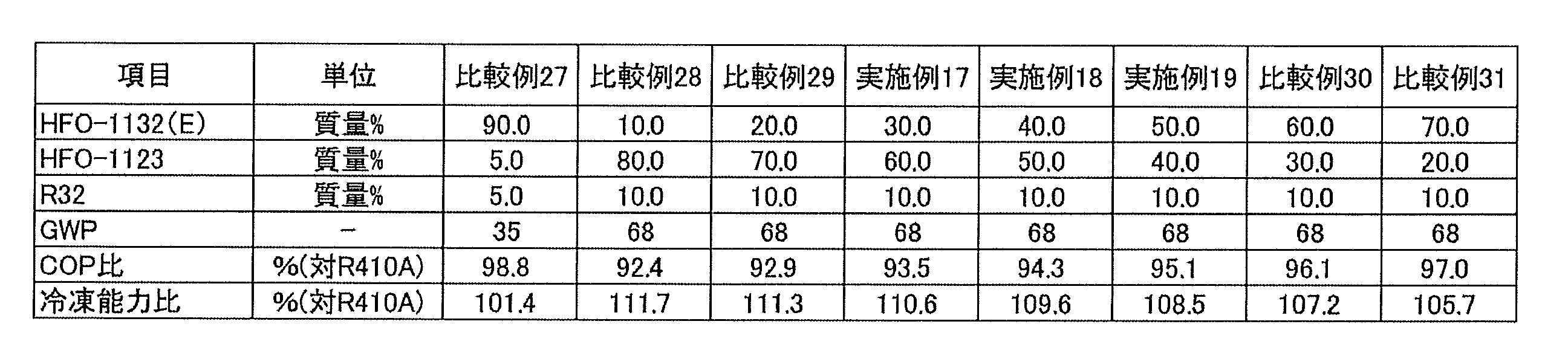


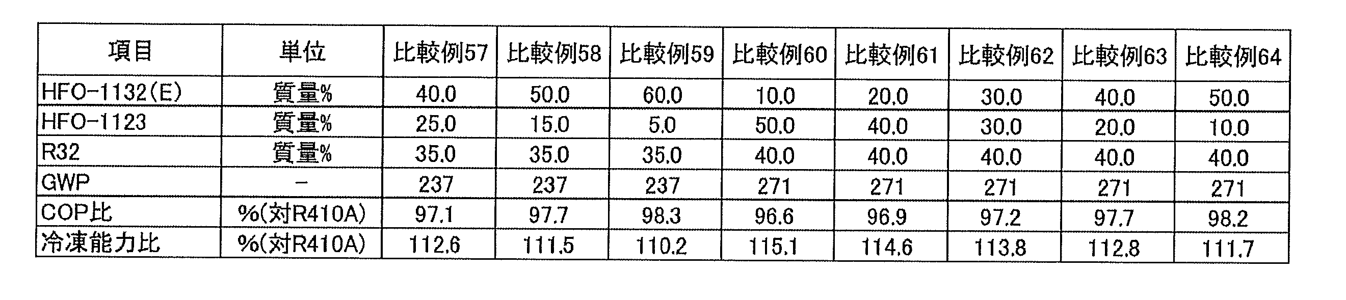

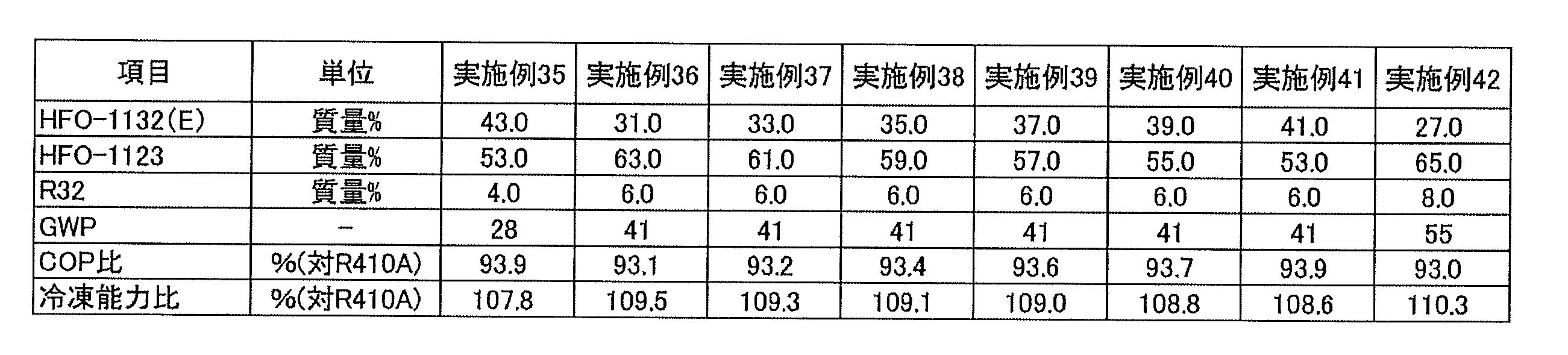


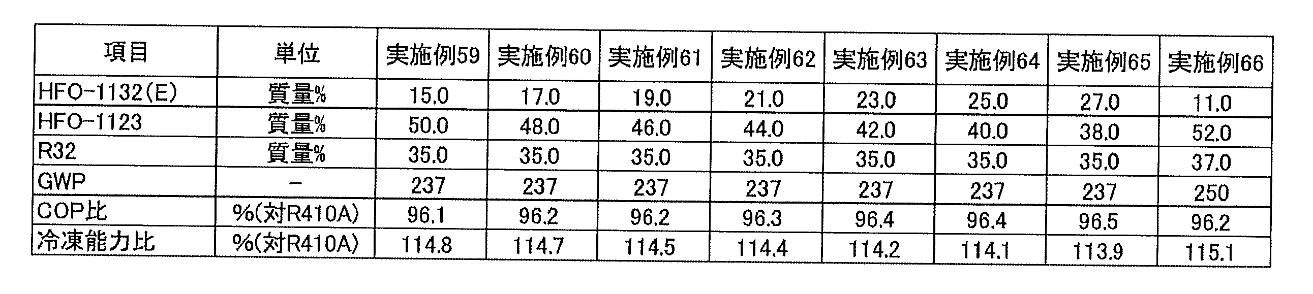


これらの結果から、HFO-1132(E)、HFO-1123及びR32の、これらの総和を基準とする質量%をそれぞれx、y及びzとするとき、HFO-1132(E)、HFO-1123及びR32の総和が100質量%となり、点(0.0, 100.0, 0.0)と点(0.0, 0.0, 100.0)とを結ぶ線分を底辺とし、点(0.0, 100.0, 0.0)を左側とする3成分組成図において、座標(x,y,z)が、
点O(100.0, 0.0, 0.0)、
点A’’(63.0, 0.0, 37.0)、
点B’’(0.0, 63.0, 37.0)及び
点(0.0, 100.0, 0.0)
の4点をそれぞれ結ぶ線分で囲まれる図形の範囲内又は前記線分上にある場合、GWPが250以下となることが判る。 From these results, HFO-1132 (E), HFO-1123 and HFO-1123 and HFO-1123 and HFO-1123 and H32, respectively, when the mass% of HFO-1132 (E), HFO-1123 and R32 based on the total of these are respectively x, y and z A total of R32 is 100% by mass, and a three-component composition with the line connecting point (0.0, 100.0, 0.0) and point (0.0, 0.0, 100.0) as the base and point (0.0, 100.0, 0.0) as the left side In the figure, the coordinates (x, y, z) are
Point O (100.0, 0.0, 0.0),
Point A '' (63.0, 0.0, 37.0),
Point B '' (0.0, 63.0, 37.0) and Point (0.0, 100.0, 0.0)
When it exists in the range of the figure enclosed by the line segment which respectively connects 4 points of, or on the said line segment, it turns out that GWP becomes 250 or less.
また、同様に、座標(x,y,z)が、
点O(100.0, 0.0, 0.0)、
点A’(81.6, 0.0, 18.4)、
点B’(0.0, 81.6, 18.4)及び
点(0.0, 100.0, 0.0)
の4点をそれぞれ結ぶ線分で囲まれる図形の範囲内又は前記線分上にある場合、GWPが125以下となることが判る。 Similarly, the coordinates (x, y, z) are
Point O (100.0, 0.0, 0.0),
Point A '(81.6, 0.0, 18.4),
Point B '(0.0, 81.6, 18.4) and point (0.0, 100.0, 0.0)
When it exists in the range of the figure enclosed by the line segment which respectively connects 4 points of, or on the said line segment, it turns out that GWP becomes 125 or less.
また、同様に、座標(x,y,z)が、
点O(100.0, 0.0, 0.0)、
点A(90.5, 0.0, 9.5)、
点B(0.0, 90.5, 9.5)及び
点(0.0, 100.0, 0.0)
の4点をそれぞれ結ぶ線分で囲まれる図形の範囲内又は前記線分上にある場合、GWPが65以下となることが判る。 Similarly, the coordinates (x, y, z) are
Point O (100.0, 0.0, 0.0),
Point A (90.5, 0.0, 9.5),
Point B (0.0, 90.5, 9.5) and Point (0.0, 100.0, 0.0)
When it exists in the range of the figure enclosed by the line segment which respectively connects 4 points of, or on the said line segment, it turns out that GWP becomes 65 or less.
また、同様に、座標(x,y,z)が、
点C(50.0, 31.6, 18.4)、
点U(28.7, 41.2, 30.1)及び
点D(52.2, 38.3, 9.5)
の3点をそれぞれ結ぶ線分の左側又は前記線分上にある場合、R410Aを基準とするCOP比が96%以上となることが判る。ただし、前記線分CUは、座標(-0.0538z2+0.7888z+53.701, 0.0538z2-1.7888z+46.299, z)前記線分UDは、座標(-3.4962z2+210.71z-3146.1, 3.4962z2-211.71z+3246.1, z)で表わされる。 Similarly, the coordinates (x, y, z) are
Point C (50.0, 31.6, 18.4),
Point U (28.7, 41.2, 30.1) and Point D (52.2, 38.3, 9.5)
It can be seen that the COP ratio based on R410A is 96% or more when it is on the left side of the line segment connecting the three points of or on the line segment. However, the line segment CU has coordinates (−0.0538z 2 + 0.7888z + 53.701, 0.0538z 2 −1.7888z + 46.299, z), and the line segment UD has coordinates (−3.4962z 2 + 210.71z−3146.1, 3.4962 z 2 -211.71 z + 3246.1, z).
線分CU上の点は、点C,比較例10,点Uの3点から最小二乗法にて求められる。
The point on the line segment CU is obtained from the three points of the point C, the comparative example 10, and the point U by the least square method.
線分UD上の点は、点U,実施例2, Dの3点から最小二乗法にて求められる。
The point on the line segment UD is obtained by the least square method from the three points of the point U, the second embodiment, and the D.
また、同様に、座標(x,y,z)が、
点E(55.2, 44.8, 0.0)と、
点T(34.8, 51.0, 14.2)
点F(0.0, 76.7, 23.3)と
の3点をそれぞれ結ぶ線分の左側又は前記線分上にある場合、R410Aを基準とするCOP比が94.5%以上となることが判る。ただし、前記線分ETは、座標(-0.0547z2-0.5327z+53.4, 0.0547z2-0.4673z+46.6, z)前記線分TFは、座標(-0.0982z2+0.9622z+40.931, 0.0982z2-1.9622z+59.069, z)で表わされる。線分ET上の点は、点E,実施例2,Tの3点から最小二乗法にて求められる。 Similarly, the coordinates (x, y, z) are
Point E (55.2, 44.8, 0.0),
Point T (34.8, 51.0, 14.2)
When it is on the left side of the line segment connecting the three points with the point F (0.0, 76.7, 23.3) or on the line segment, it is understood that the COP ratio based on R410A is 94.5% or more. However, the line segment ET the coordinates (-0.0547z 2 -0.5327z + 53.4, 0.0547z 2 -0.4673z + 46.6, z) the segment TF is coordinates (-0.0982z 2 + 0.9622z + 40.931, 0.0982 z 2 −1.9622 z + 59.069, z). The point on the line segment ET is obtained by the least square method from the three points of the point E, Example 2, and T.
線分TG上の点は、点T,S,Fの3点から最小二乗法にて求められる。
The point on the line segment TG is obtained by the least square method from the three points T, S, and F.
また、同様に、座標(x,y,z)が、
点G(0.0, 76.7, 23.3)、
点R(21.0, 69.5, 9.5)及び
点H(0.0, 85.9, 14.1)
の3点をそれぞれ結ぶ線分の左側又は前記線分上にある場合、R410Aを基準とするCOP比が93%以上となることが判る。ただし、前記線分GRは、座標(-0.0491z2-1.1544z+38.5, 0.0491z2+0.1544z+61.5, z)で表わされ、かつ前記線分RHは、座標(-0.3123z2+4.234z+11.06, 0.3123z2-5.234z+88.94, z)で表わされる。 Similarly, the coordinates (x, y, z) are
Point G (0.0, 76.7, 23.3),
Point R (21.0, 69.5, 9.5) and point H (0.0, 85.9, 14.1)
When it exists on the left side of the line segment which ties three points of, respectively, or on the said line segment, it turns out that COP ratio on the basis of R410A becomes 93% or more. However, the line segment GR is represented by coordinates (−0.0491 2 -1.1544z + 38.5, 0.0491z 2 + 0.1544z + 61.5, z), and the line segment RH is represented by coordinates (−0.3123z 2 + 4.234z + 11.06, 0.3123z 2 -5.234z + 88.94, represented by z).
線分GR上の点は、点G,実施例5、点Rの3点から最小二乗法にて求められる。
The point on the line segment GR is obtained from the three points of the point G, the fifth embodiment, and the point R by the least square method.
線分RH上の点は、点R,実施例7,点Hの3点から最小二乗法にて求められる。
The point on the line segment RH is obtained from the three points of the point R, the example 7, and the point H by the least square method.
一方、比較例8、9、13、15、17及び18等に示されるようにR32を含まない場合、二重結合を持つHFO-1132(E)及びHFO-1123の濃度が相対的に高くなり、冷媒化合物において分解等の変質や重合を招くため、好ましくない。
On the other hand, as shown in Comparative Examples 8, 9, 13, 15, 17 and 18 etc., when R32 is not contained, the concentrations of HFO-1132 (E) having a double bond and HFO-1123 become relatively high. This is not preferable because it causes deterioration or polymerization such as decomposition in the refrigerant compound.
(6)第1実施形態
図面を参照しながら、第1実施形態に係る冷凍装置である熱負荷処理システム100について説明する。なお、以下の実施形態は、具体例であって、技術的範囲を限定するものではなく、要旨を逸脱しない範囲で適宜変更が可能である。また、以下の説明では、「上」、「下」、「左」、「右」、「前(正面)」、「後(背面)」等の方向を示す表現を用いる場合がある。特に断りのない場合、これらの方向は、図中に矢印で示した方向を示している。なお、これらの方向に関する表現は、あくまでも実施形態の理解を容易にするために用いるものであり、本開示に係る思想を特に限定するものではない。 (6) First Embodiment A heatload processing system 100 which is a refrigeration apparatus according to a first embodiment will be described with reference to the drawings. The following embodiments are specific examples and do not limit the technical scope, and appropriate modifications can be made without departing from the scope of the invention. Moreover, in the following description, the expression which shows directions, such as "upper", "lower", "left", "right", "front (front)", "rear (back)", may be used. Unless otherwise noted, these directions indicate the directions indicated by the arrows in the figure. In addition, the expression regarding these directions is only used in order to facilitate the understanding of the embodiment, and the idea according to the present disclosure is not particularly limited.
図面を参照しながら、第1実施形態に係る冷凍装置である熱負荷処理システム100について説明する。なお、以下の実施形態は、具体例であって、技術的範囲を限定するものではなく、要旨を逸脱しない範囲で適宜変更が可能である。また、以下の説明では、「上」、「下」、「左」、「右」、「前(正面)」、「後(背面)」等の方向を示す表現を用いる場合がある。特に断りのない場合、これらの方向は、図中に矢印で示した方向を示している。なお、これらの方向に関する表現は、あくまでも実施形態の理解を容易にするために用いるものであり、本開示に係る思想を特に限定するものではない。 (6) First Embodiment A heat
(6-1)全体構成
図16は、熱負荷処理システム100の概略構成図である。熱負荷処理システム100は、設置環境において熱負荷を処理するためのシステムである。本実施形態において、熱負荷処理システム100は、対象空間の空気調和を行う空調システムである。 (6-1) Overall Configuration FIG. 16 is a schematic configuration diagram of the thermalload processing system 100. As shown in FIG. The thermal load processing system 100 is a system for processing a thermal load in an installation environment. In the present embodiment, the heat load processing system 100 is an air conditioning system that performs air conditioning of the target space.
図16は、熱負荷処理システム100の概略構成図である。熱負荷処理システム100は、設置環境において熱負荷を処理するためのシステムである。本実施形態において、熱負荷処理システム100は、対象空間の空気調和を行う空調システムである。 (6-1) Overall Configuration FIG. 16 is a schematic configuration diagram of the thermal
熱負荷処理システム100は、主として、複数(ここでは4台)の熱源側ユニット10と、熱交換器ユニット30と、複数(ここでは4台)の利用側ユニット60と、複数(ここでは4本)の液側連絡管LPと、複数(ここでは4本)のガス側連絡管GPと、第1熱媒体連絡管H1および第2熱媒体連絡管H2と、冷媒漏洩センサ70と、熱負荷処理システム100の動作を制御するコントローラ80と、を有している。
The thermal load processing system 100 mainly includes a plurality of (four in this case) heat source side units 10, a heat exchanger unit 30, a plurality (four in this case) use side units 60, and a plurality (four in this case) ), The plurality of (four in this case) gas side communication pipes GP, the first heat medium communication pipe H1 and the second heat medium communication pipe H2, the refrigerant leakage sensor 70, and the heat load processing And a controller 80 that controls the operation of the system 100.
熱負荷処理システム100では、熱源側ユニット10および熱交換器ユニット30が液側連絡管LPおよびガス側連絡管GPで接続されることで冷媒が循環する冷媒回路RCが構成されている。熱負荷処理システム100では、複数の熱源側ユニット10が並列に配置されていることに関連して、複数(ここでは4つ)の冷媒回路RCが構成されている。換言すると、熱負荷処理システム100では、複数の熱源側ユニット10および熱交換器ユニット30によって複数の冷媒回路RCが構成されている。熱負荷処理システム100は、各冷媒回路RCにおいて蒸気圧縮式の冷凍サイクルを行う。
In the heat load processing system 100, the heat source side unit 10 and the heat exchanger unit 30 are connected by the liquid side communication pipe LP and the gas side communication pipe GP, thereby forming a refrigerant circuit RC in which the refrigerant circulates. In the heat load processing system 100, a plurality of (here, four) refrigerant circuits RC are configured in association with the plurality of heat source side units 10 being arranged in parallel. In other words, in the heat load processing system 100, the plurality of heat source units 10 and the heat exchanger unit 30 constitute a plurality of refrigerant circuits RC. The heat load processing system 100 performs a vapor compression refrigeration cycle in each refrigerant circuit RC.
本実施形態では、冷媒回路RCに封入される冷媒は、1,2-ジフルオロエチレンを含む混合冷媒であり、上述した冷媒A~Eのいずれかを用いることができる。
In the present embodiment, the refrigerant sealed in the refrigerant circuit RC is a mixed refrigerant containing 1,2-difluoroethylene, and any of the above-described refrigerants A to E can be used.
熱負荷処理システム100では、熱交換器ユニット30および利用側ユニット60が第1熱媒体連絡管H1および第2熱媒体連絡管H2で接続されることで、熱媒体が循環する熱媒体回路HCが構成されている。換言すると、熱負荷処理システム100では、熱交換器ユニット30および利用側ユニット60によって熱媒体回路HCが構成されている。熱媒体回路HCにおいては、熱交換器ユニット30のポンプ36が駆動することによって熱媒体が循環する。
In the heat load processing system 100, the heat exchanger unit 30 and the use side unit 60 are connected by the first heat medium communication pipe H1 and the second heat medium communication pipe H2, so that the heat medium circuit HC in which the heat medium circulates. It is configured. In other words, in the heat load processing system 100, the heat exchanger circuit 30 and the use side unit 60 constitute the heat medium circuit HC. In the heat medium circuit HC, the heat medium is circulated by driving the pump 36 of the heat exchanger unit 30.
本実施形態では、熱媒体回路HCに封入される熱媒体は、例えば、水やブラインなどの液媒体である。ブラインは、例えば、塩化ナトリウム水溶液、塩化カルシウム水溶液、エチレングリコール水溶液や、プロピレングリコール水溶液等を含む。なお、液媒体の種類はここに例示したものに限定されるものではなく、適宜選択されればよい。特に本実施形態では、熱媒体としてブラインが使用されるものとする。
In the present embodiment, the heat medium sealed in the heat medium circuit HC is, for example, a liquid medium such as water or brine. The brine includes, for example, an aqueous solution of sodium chloride, an aqueous solution of calcium chloride, an aqueous solution of ethylene glycol, an aqueous solution of propylene glycol and the like. In addition, the kind of liquid medium is not limited to what was illustrated here, What is necessary is just to be selected suitably. Particularly in the present embodiment, brine is used as a heat medium.
(6-2)詳細構成
(6-2-1)熱源側ユニット
本実施形態では、熱負荷処理システム100は、4台の熱源側ユニット10を有する(図16参照)。そして、熱交換器ユニット30は、4台の熱源側ユニット10において冷却/加熱された冷媒で、液媒体を冷却/加熱する。ただし、熱源側ユニット10の台数は例示であって、その台数は4台に限定されるものではない。熱源側ユニット10は、1~3台であってもよいし、5台以上であってもよい。なお、図16では、4台の熱源側ユニット10のうち1台についてのみ内部構成を描画し、他の3台の内部構成の描画は省略している。描画を省略した熱源側ユニット10についても、以下で説明する熱源側ユニット10と同様の構成を有する。 (6-2) Detailed Configuration (6-2-1) Heat Source Side Unit In the present embodiment, the heatload processing system 100 has four heat source side units 10 (see FIG. 16). The heat exchanger unit 30 cools / heats the liquid medium with the refrigerant cooled / heated in the four heat source units 10. However, the number of heat source side units 10 is an example, and the number is not limited to four. The number of heat source units 10 may be one to three, or five or more. In FIG. 16, the internal configuration of only one of the four heat source units 10 is depicted, and the depiction of the other three internal configurations is omitted. The heat source side unit 10 whose drawing is omitted also has the same configuration as the heat source side unit 10 described below.
(6-2-1)熱源側ユニット
本実施形態では、熱負荷処理システム100は、4台の熱源側ユニット10を有する(図16参照)。そして、熱交換器ユニット30は、4台の熱源側ユニット10において冷却/加熱された冷媒で、液媒体を冷却/加熱する。ただし、熱源側ユニット10の台数は例示であって、その台数は4台に限定されるものではない。熱源側ユニット10は、1~3台であってもよいし、5台以上であってもよい。なお、図16では、4台の熱源側ユニット10のうち1台についてのみ内部構成を描画し、他の3台の内部構成の描画は省略している。描画を省略した熱源側ユニット10についても、以下で説明する熱源側ユニット10と同様の構成を有する。 (6-2) Detailed Configuration (6-2-1) Heat Source Side Unit In the present embodiment, the heat
熱源側ユニット10は、空気を熱源として、冷媒を冷却又は加熱するユニットである。各熱源側ユニット10は、液側連絡管LPおよびガス側連絡管GPを介して熱交換器ユニット30に個別に接続されている。換言すると、各熱源側ユニット10は、熱交換器ユニット30と共に、個別に冷媒回路RCを構成する。すなわち、熱負荷処理システム100では、複数(ここでは4台)の熱源側ユニット10と、熱交換器ユニット30と、が個別に接続されることで、複数(ここでは4つ)の冷媒回路RCが構成されている。なお、各冷媒回路RCは、分離しており連通していない。
The heat source side unit 10 is a unit that cools or heats the refrigerant using air as a heat source. Each heat source side unit 10 is individually connected to the heat exchanger unit 30 via the liquid side communication pipe LP and the gas side communication pipe GP. In other words, each heat source side unit 10, together with the heat exchanger unit 30, individually constitutes the refrigerant circuit RC. That is, in the thermal load processing system 100, the plurality of (four in this case) heat source side units 10 and the heat exchanger unit 30 are separately connected to each other, whereby a plurality of (four in this case) refrigerant circuits RC Is configured. The refrigerant circuits RC are separated and not in communication.
熱源側ユニット10は、設置場所を限定されるものではないが、例えば屋上や建物の周辺のスペース等に設置される。熱源側ユニット10は、液側連絡管LP、ガス側連絡管GPを介して熱交換器ユニット30と接続されており、冷媒回路RCの一部を構成している。
The heat source side unit 10 is not limited to the installation location, but is installed, for example, on the rooftop or a space around the building. The heat source side unit 10 is connected to the heat exchanger unit 30 via the liquid side communication pipe LP and the gas side communication pipe GP, and constitutes a part of the refrigerant circuit RC.
熱源側ユニット10は、冷媒回路RCを構成する機器として、主として、複数の冷媒配管(第1配管P1-第11配管P11)と、圧縮機11と、アキュームレータ12と、四路切換弁13と、熱源側熱交換器14と、過冷却器15と、熱源側第1制御弁16と、熱源側第2制御弁17と、液側閉鎖弁18と、ガス側閉鎖弁19と、を有している。
The heat source side unit 10 mainly includes a plurality of refrigerant pipes (first pipe P1 to eleventh pipe P11), a compressor 11, an accumulator 12, and a four-way switching valve 13 as devices constituting the refrigerant circuit RC. A heat source side heat exchanger 14, a subcooler 15, a heat source side first control valve 16, a heat source side second control valve 17, a liquid side shut-off valve 18, and a gas side shut-off valve 19 There is.
第1配管P1は、ガス側閉鎖弁19と、四路切換弁13の第1ポートと、を接続する。第2配管P2は、アキュームレータ12の入口ポートと、四路切換弁13の第2ポートと、を接続する。第3配管P3は、アキュームレータ12の出口ポートと、圧縮機11の吸入ポートと、を接続する。第4配管P4は、圧縮機11の吐出ポートと、四路切換弁13の第3ポートと、を接続する。第5配管P5は、四路切換弁13の第4ポートと、熱源側熱交換器14のガス側出入口と、を接続する。第6配管P6は、熱源側熱交換器14の液側出入口と、熱源側第1制御弁16の一端と、を接続する。第7配管P7は、熱源側第1制御弁16の他端と、過冷却器15のメイン流路151の一端と、を接続する。第8配管P8は、過冷却器15のメイン流路151の他端と、液側閉鎖弁18の一端と、を接続する。
The first pipe P1 connects the gas-side shutoff valve 19 and the first port of the four-way switching valve 13. The second pipe P <b> 2 connects the inlet port of the accumulator 12 and the second port of the four-way switching valve 13. The third pipe P3 connects the outlet port of the accumulator 12 and the suction port of the compressor 11. The fourth pipe P4 connects the discharge port of the compressor 11 and the third port of the four-way switching valve 13. The fifth pipe P <b> 5 connects the fourth port of the four-way switching valve 13 and the gas side inlet / outlet of the heat source side heat exchanger 14. The sixth pipe P6 connects the liquid side inlet / outlet of the heat source side heat exchanger 14 and one end of the heat source side first control valve 16. The seventh pipe P7 connects the other end of the heat source side first control valve 16 and one end of the main flow path 151 of the subcooler 15. The eighth pipe P <b> 8 connects the other end of the main flow path 151 of the subcooler 15 and one end of the liquid side shut-off valve 18.
第9配管P9は、第6配管P6の両端間の部分と、熱源側第2制御弁17の一端と、を接続する。第10配管P10は、熱源側第2制御弁17の他端と、過冷却器15のサブ流路152の一端と、を接続する。第11配管P11は、過冷却器15のサブ流路152の他端と、圧縮機11のインジェクションポートと、を接続する。
The ninth pipe P9 connects a portion between both ends of the sixth pipe P6 and one end of the heat source side second control valve 17. The tenth pipe P10 connects the other end of the heat source side second control valve 17 and one end of the sub flow path 152 of the subcooler 15. The eleventh pipe P11 connects the other end of the sub flow path 152 of the subcooler 15 to the injection port of the compressor 11.
なお、これらの冷媒配管(P1―P11)は、実際には、単一の配管で構成されてもよいし、継手等を介して複数の配管が接続されることで構成されてもよい。
These refrigerant pipes (P1 to P11) may actually be configured by a single pipe, or may be configured by connecting a plurality of pipes via a joint or the like.
圧縮機11は、冷凍サイクルにおける低圧の冷媒を高圧になるまで圧縮する機器である。本実施形態では、圧縮機11は、ロータリ式やスクロール式等の容積式の圧縮要素が圧縮機モータ(図示省略)によって回転駆動される密閉式構造を有している。圧縮機モータは、インバータにより運転周波数の制御が可能である。すなわち、圧縮機11は、容量制御可能に構成されている。但し、圧縮機11は、容量が一定の圧縮機であってもよい。
The compressor 11 is a device that compresses low-pressure refrigerant in the refrigeration cycle to high pressure. In the present embodiment, the compressor 11 has a closed type structure in which a rotary type or scroll type positive displacement type compression element is rotationally driven by a compressor motor (not shown). The compressor motor can control the operating frequency by an inverter. That is, the compressor 11 is configured to be capable of capacity control. However, the compressor 11 may be a compressor having a fixed capacity.
アキュームレータ12は、圧縮機11に液冷媒が過度に吸入されることを抑制するための容器である。アキュームレータ12は、冷媒回路RCに充填されている冷媒量に応じて所定の容積を有している。
The accumulator 12 is a container for suppressing excessive suction of the liquid refrigerant into the compressor 11. The accumulator 12 has a predetermined volume according to the amount of refrigerant charged in the refrigerant circuit RC.
四路切換弁13は、冷媒回路RCにおける冷媒の流れを切り換えるための流路切換機構である。四路切換弁13は、正サイクル状態と逆サイクル状態とを切り換えられる。四路切換弁13は、正サイクル状態となると、第1ポート(第1配管P1)と第2ポート(第2配管P2)とを連通させるとともに第3ポート(第4配管P4)と第4ポート(第5配管P5)とを連通させる(図16の四路切換弁13の実線を参照)。四路切換弁13は、逆サイクル状態となると、第1ポート(第1配管P1)と第3ポート(第4配管P4)とを連通させるとともに第2ポート(第2配管P2)と第4ポート(第5配管P5)とを連通させる(図16の四路切換弁13の破線を参照)。
The four-way switching valve 13 is a flow path switching mechanism for switching the flow of the refrigerant in the refrigerant circuit RC. The four-way switching valve 13 is switched between the forward cycle state and the reverse cycle state. The four-way switching valve 13 brings the first port (first pipe P1) into communication with the second port (second pipe P2) and the third port (fourth pipe P4) and the fourth port when in the positive cycle state. (The fifth pipe P5) is communicated (see the solid line of the four-way switching valve 13 in FIG. 16). When the four-way switching valve 13 is in the reverse cycle state, the first port (first pipe P1) and the third port (fourth pipe P4) are communicated with each other and the second port (second pipe P2) and the fourth port (Communicate with the fifth pipe P5) (see the broken line of the four-way switching valve 13 in FIG. 16).
熱源側熱交換器14は、冷媒の凝縮器(又は放熱器)又は蒸発器として機能する熱交換器である。熱源側熱交換器14は、正サイクル運転(四路切換弁13が正サイクル状態にある運転)時には、冷媒の凝縮器として機能する。また、熱源側熱交換器14は、逆サイクル運転(四路切換弁13が逆サイクル状態にある運転)時には、冷媒の蒸発器として機能する。熱源側熱交換器14は、複数の伝熱管と、伝熱フィンと、を含む(図示省略)。熱源側熱交換器14は、伝熱管内の冷媒と、伝熱管又は伝熱フィンの周囲を通過する空気(後述の熱源側空気流)と、の間で熱交換が行われるように構成されている。
The heat source side heat exchanger 14 is a heat exchanger that functions as a refrigerant condenser (or a radiator) or an evaporator. The heat source side heat exchanger 14 functions as a condenser of the refrigerant in the positive cycle operation (operation in which the four-way switching valve 13 is in the positive cycle state). The heat source side heat exchanger 14 also functions as a refrigerant evaporator during reverse cycle operation (operation in which the four-way switching valve 13 is in the reverse cycle state). The heat source side heat exchanger 14 includes a plurality of heat transfer tubes and heat transfer fins (not shown). The heat source side heat exchanger 14 is configured such that heat exchange is performed between the refrigerant in the heat transfer pipe and the air (heat source side air flow described later) passing around the heat transfer pipe or the heat transfer fin. There is.
過冷却器15は、流入する冷媒を過冷却状態の液冷媒とする熱交換器である。過冷却器15は、例えば二重管熱交換器であり、過冷却器15にはメイン流路151とサブ流路152とが構成されている。過冷却器15は、メイン流路151およびサブ流路152を流れる冷媒が熱交換を行うように構成されている。
The subcooler 15 is a heat exchanger that uses the inflowing refrigerant as a liquid refrigerant in a subcooling state. The subcooler 15 is, for example, a double-pipe heat exchanger, and the subcooler 15 is configured with a main flow path 151 and a sub flow path 152. The subcooler 15 is configured such that the refrigerant flowing through the main flow passage 151 and the sub flow passage 152 exchanges heat.
熱源側第1制御弁16は、開度制御が可能な電子膨張弁であり、開度に応じて流入する冷媒を減圧する又は流量調節する。熱源側第1制御弁16は、開状態と閉状態とを切換可能である。熱源側第1制御弁16は、熱源側熱交換器14と過冷却器15(メイン流路151)との間に配置されている。
The heat source side first control valve 16 is an electronic expansion valve capable of controlling the opening degree, and decompresses or adjusts the flow rate of the inflowing refrigerant according to the opening degree. The heat source side first control valve 16 can switch between an open state and a closed state. The heat source side first control valve 16 is disposed between the heat source side heat exchanger 14 and the subcooler 15 (main flow passage 151).
熱源側第2制御弁17は、開度制御が可能な電子膨張弁であり、開度に応じて流入する冷媒を減圧する又は流量調節する。熱源側第2制御弁17は、開状態と閉状態とを切換可能である。熱源側第2制御弁17は、熱源側熱交換器14と過冷却器15(サブ流路152)との間に配置されている。
The heat source side second control valve 17 is an electronic expansion valve capable of opening degree control, and decompresses or adjusts the flow rate of the inflowing refrigerant according to the opening degree. The heat source side second control valve 17 can switch between an open state and a closed state. The heat source side second control valve 17 is disposed between the heat source side heat exchanger 14 and the subcooler 15 (sub flow path 152).
液側閉鎖弁18は、第8配管P8と液側連絡管LPとの接続部分に配置された手動弁である。液側閉鎖弁18は、一端が第8配管P8に接続され他端が液側連絡管LPに接続されている。
The liquid side shut-off valve 18 is a manual valve disposed at the connection between the eighth pipe P8 and the liquid side communication pipe LP. One end of the liquid side shut-off valve 18 is connected to the eighth pipe P8, and the other end is connected to the liquid side communication pipe LP.
ガス側閉鎖弁19は、第1配管P1とガス側連絡管GPとの接続部分に配置された手動弁である。ガス側閉鎖弁19は、一端が第1配管P1に接続され他端がガス側連絡管GPに接続されている。
The gas side shut-off valve 19 is a manual valve disposed at a connection portion between the first pipe P1 and the gas side communication pipe GP. One end of the gas side shut-off valve 19 is connected to the first pipe P1, and the other end is connected to the gas side communication pipe GP.
また、熱源側ユニット10は、熱源側熱交換器14を通過する熱源側空気流を生成する熱源側ファン20を有している。熱源側ファン20は、熱源側熱交換器14を流れる冷媒の冷却源又は加熱源としての熱源側空気流を熱源側熱交換器14に供給する送風機である。熱源側ファン20は、駆動源である熱源側ファンモータ(図示省略)を含み、状況に応じて発停および回転数を適宜制御される。
The heat source side unit 10 also has a heat source side fan 20 that generates a heat source side air flow passing through the heat source side heat exchanger 14. The heat source side fan 20 is a blower that supplies the heat source side heat exchanger 14 with a heat source side air flow as a cooling source of the refrigerant flowing through the heat source side heat exchanger 14 or as a heating source. The heat source side fan 20 includes a heat source side fan motor (not shown) which is a drive source, and the start and stop and the number of rotations are appropriately controlled according to the situation.
また、熱源側ユニット10には、冷媒回路RC内の冷媒の状態(主に圧力又は温度)を検出するための複数の熱源側センサS1(図18参照)が配置されている。熱源側センサS1は、圧力センサや、サーミスタ又は熱電対等の温度センサである。熱源側センサS1には、例えば、圧縮機11の吸入側(第3配管P3)における冷媒の温度(吸入温度)を検出する第1温度センサ21、又は圧縮機11の吐出側(第4配管P4)における冷媒の温度(吐出温度)を検出する第2温度センサ22が含まれている。また、熱源側センサS1には、例えば、熱源側熱交換器14の液側(第6配管P6)の冷媒の温度を検出する第3温度センサ23、第8配管P8における冷媒の温度を検出する第4温度センサ24、又は第11配管P11における冷媒の温度を検出する第5温度センサ25が含まれている。また、熱源側センサS1には、例えば、圧縮機11の吸入側(第2配管P2)における冷媒の圧力(吸入圧力)を検出する第1圧力センサ27、圧縮機11の吐出側(第4配管P4)における冷媒の圧力(吐出圧力)を検出する第2圧力センサ28が含まれている。
In the heat source side unit 10, a plurality of heat source side sensors S1 (see FIG. 18) for detecting the state (mainly pressure or temperature) of the refrigerant in the refrigerant circuit RC are disposed. The heat source side sensor S1 is a pressure sensor, or a temperature sensor such as a thermistor or a thermocouple. The heat source sensor S1 may be, for example, a first temperature sensor 21 that detects the temperature (suction temperature) of the refrigerant on the suction side (third pipe P3) of the compressor 11, or the discharge side of the compressor 11 (fourth pipe P4). And a second temperature sensor 22 for detecting the temperature of the refrigerant (discharge temperature). Further, the heat source sensor S1 detects, for example, the temperature of the refrigerant in the third temperature sensor 23 for detecting the temperature of the refrigerant on the liquid side (sixth pipe P6) of the heat source side heat exchanger 14 and the eighth pipe P8. The fourth temperature sensor 24 or the fifth temperature sensor 25 for detecting the temperature of the refrigerant in the eleventh pipe P11 is included. In the heat source side sensor S1, for example, a first pressure sensor 27 for detecting the pressure (suction pressure) of the refrigerant on the suction side (second pipe P2) of the compressor 11, and a discharge side of the compressor 11 (fourth pipe A second pressure sensor 28 is included which detects the pressure (discharge pressure) of the refrigerant at P4).
また、熱源側ユニット10は、熱源側ユニット10に含まれる各機器の動作・状態を制御する熱源側ユニット制御部29を有している。熱源側ユニット制御部29は、その機能を実行するために、各種電気回路や、マイクロプロセッサやマイクロプロセッサが実行するプログラムが記憶されたメモリチップを有するマイクロコンピュータ等を有している。熱源側ユニット制御部29は、熱源側ユニット10に含まれる各機器(11、13、16、17、20等)や熱源側センサS1と電気的に接続されており、互いに信号の入出力を行う。また、熱源側ユニット制御部29は、熱交換器ユニット30の熱交換器ユニット制御部49(後述)等と通信線を介して電気的に接続されており、互いに制御信号の送受信を行う。
In addition, the heat source side unit 10 includes a heat source side unit control unit 29 that controls the operation / state of each device included in the heat source side unit 10. The heat source side unit control unit 29 has various electric circuits and a microcomputer having a memory chip in which a microprocessor and a program executed by the microprocessor are stored in order to execute the function. The heat source side unit control unit 29 is electrically connected to the devices (11, 13, 16, 17, 20, etc.) included in the heat source side unit 10 and the heat source side sensor S1, and inputs and outputs signals to each other. . Further, the heat source side unit control unit 29 is electrically connected to a heat exchanger unit control unit 49 (described later) of the heat exchanger unit 30 and the like via a communication line, and transmits and receives control signals to and from each other.
(6-2-2)熱交換器ユニット
熱交換器ユニット30は、熱媒体と冷媒とを熱交換させることで、熱媒体の冷却および加熱の少なくとも一方を行う機器である。本実施形態では、熱交換器ユニット30は、熱媒体と冷媒とを熱交換させることで、熱媒体の冷却および加熱を行う。熱交換器ユニット30で液冷媒により冷却又は加熱された熱媒体は、利用側ユニット60へと送られる。 (6-2-2) Heat Exchanger Unit Theheat exchanger unit 30 is a device that performs at least one of cooling and heating of the heat medium by exchanging heat between the heat medium and the refrigerant. In the present embodiment, the heat exchanger unit 30 performs cooling and heating of the heat medium by exchanging heat between the heat medium and the refrigerant. The heat medium cooled or heated by the liquid refrigerant in the heat exchanger unit 30 is sent to the use side unit 60.
熱交換器ユニット30は、熱媒体と冷媒とを熱交換させることで、熱媒体の冷却および加熱の少なくとも一方を行う機器である。本実施形態では、熱交換器ユニット30は、熱媒体と冷媒とを熱交換させることで、熱媒体の冷却および加熱を行う。熱交換器ユニット30で液冷媒により冷却又は加熱された熱媒体は、利用側ユニット60へと送られる。 (6-2-2) Heat Exchanger Unit The
熱交換器ユニット30は、利用側ユニット60へと送られる熱媒体と冷媒とを熱交換させることで、熱媒体の冷却又は加熱を行うユニットである。熱交換器ユニット30は、設置場所を限定されるものではないが、例えば設備機器室等の室内に設置される。熱交換器ユニット30は、各冷媒回路RCを構成する機器として、熱源側ユニット10の数(冷媒回路RCの数)と同数(ここでは4つ)の、複数の冷媒配管(冷媒配管Pa、Pb、Pc、Pd)、膨張弁31、および開閉弁32を有している。また、熱交換器ユニット30は、各冷媒回路RCおよび熱媒体回路HCを構成する機器として、熱交換器33を有している。
The heat exchanger unit 30 is a unit that cools or heats the heat medium by exchanging heat between the heat medium sent to the use side unit 60 and the refrigerant. The heat exchanger unit 30 is installed in a room such as an equipment room, though the installation location is not limited. The heat exchanger unit 30 includes a plurality of refrigerant pipes (refrigerant pipes Pa and Pb) having the same number (four in this case) as the number of heat source units 10 (the number of refrigerant circuits RC) as devices constituting each refrigerant circuit RC. , Pc, Pd), an expansion valve 31, and an on-off valve 32. Moreover, the heat exchanger unit 30 has the heat exchanger 33 as an apparatus which comprises each refrigerant circuit RC and the heat-medium circuit HC.
冷媒配管Paは、液側連絡管LPと、膨張弁31の一端と、を接続する。冷媒配管Pbは、膨張弁31の他端と、熱交換器33の一の液側冷媒出入口と、を接続する。冷媒配管Pcは、熱交換器33の一のガス側冷媒出入口と、開閉弁32の一端と、を接続する。冷媒配管Pdは、開閉弁32の他端と、ガス側連絡管GPと、を接続する。なお、これらの冷媒配管(Pa―Pd)は、実際には、単一の配管で構成されてもよいし、継手等を介して複数の配管が接続されることで構成されてもよい。
The refrigerant pipe Pa connects the liquid side communication pipe LP and one end of the expansion valve 31. The refrigerant pipe Pb connects the other end of the expansion valve 31 and one liquid-side refrigerant inlet / outlet of the heat exchanger 33. The refrigerant pipe Pc connects one gas side refrigerant inlet / outlet of the heat exchanger 33 and one end of the on-off valve 32. The refrigerant pipe Pd connects the other end of the on-off valve 32 and the gas side communication pipe GP. In addition, these refrigerant | coolant piping (Pa-Pd) may be actually comprised with a single piping, and may be comprised by connecting several piping via a coupling etc.
膨張弁31は、開度制御が可能な電子膨張弁であり、開度に応じて流入する冷媒を減圧する又は流量調節する。膨張弁31は、開状態と閉状態とを切換可能である。膨張弁31は、熱交換器33と液側連絡管LPとの間に配置されている。
The expansion valve 31 is an electronic expansion valve whose opening degree can be controlled, and depressurizes or adjusts the flow rate of the inflowing refrigerant according to the opening degree. The expansion valve 31 can switch between an open state and a closed state. The expansion valve 31 is disposed between the heat exchanger 33 and the liquid side communication pipe LP.
開閉弁32は、開状態と閉状態とを切換可能な制御弁である。開閉弁32は、閉状態時に冷媒を遮断する。開閉弁32は、熱交換器33とガス側連絡管GPとの間に配置されている。
The on-off valve 32 is a control valve capable of switching between an open state and a closed state. The on-off valve 32 shuts off the refrigerant when it is closed. The on-off valve 32 is disposed between the heat exchanger 33 and the gas side communication pipe GP.
熱交換器33には、冷媒回路RCを流れる冷媒の流路(冷媒流路RP)が複数形成されている。熱交換器33において、各冷媒流路RPは、他の冷媒流路RPと連通していない。これに関連して、熱交換器33においては、冷媒流路RPの液側出入口およびガス側出入口が、それぞれ冷媒流路RPの数と同数(ここでは4つ)形成されている。また、熱交換器33には、熱媒体回路HCを流れる熱媒体の流路(熱媒体流路HP)が形成されている。
In the heat exchanger 33, a plurality of refrigerant flow paths (refrigerant flow paths RP) flowing through the refrigerant circuit RC are formed. In the heat exchanger 33, each refrigerant channel RP is not in communication with another refrigerant channel RP. In relation to this, in the heat exchanger 33, the liquid side inlet / outlet and the gas side inlet / outlet of the refrigerant flow channel RP are respectively formed in the same number (here four) as the number of the refrigerant flow channels RP. Further, in the heat exchanger 33, a flow path (heat medium flow path HP) of the heat medium flowing through the heat medium circuit HC is formed.
より具体的に、熱交換器33は、第1熱交換器34および第2熱交換器35を含んでいる。第1熱交換器34および第2熱交換器35は、別体として構成されている。第1熱交換器34および第2熱交換器35においては、分離した2つの冷媒流路RPがそれぞれ形成されている。第1熱交換器34および第2熱交換器35では、各冷媒流路RPの一端が、対応する冷媒回路RCの冷媒配管Pbに接続されており、各冷媒流路RPの他端が対応する冷媒回路RCの冷媒配管Pcに接続されている。第1熱交換器34では、熱媒体流路HPの一端が後述の熱媒体配管Hbに接続されており、熱媒体流路HPの他端が後述の熱媒体配管Hcに接続されている。第2熱交換器35では、熱媒体流路HPの一端が後述のHcに接続されており、熱媒体流路HPの他端が後述の熱媒体配管Hdに接続されている。第1熱交換器34および第2熱交換器35の熱媒体流路HPは、熱媒体回路HCにおいて直列に並んでいる。第1熱交換器34および第2熱交換器35は、各冷媒流路RP(冷媒回路RC)を流れる冷媒と、熱媒体流路HP(熱媒体回路HC)を流れる熱媒体と、で熱交換が行われるように構成されている。
More specifically, the heat exchanger 33 includes a first heat exchanger 34 and a second heat exchanger 35. The first heat exchanger 34 and the second heat exchanger 35 are configured separately. In the first heat exchanger 34 and the second heat exchanger 35, two separate refrigerant channels RP are formed respectively. In the first heat exchanger 34 and the second heat exchanger 35, one end of each refrigerant flow channel RP is connected to the refrigerant pipe Pb of the corresponding refrigerant circuit RC, and the other end of each refrigerant flow channel RP corresponds It is connected to the refrigerant pipe Pc of the refrigerant circuit RC. In the first heat exchanger 34, one end of the heat medium channel HP is connected to a heat medium pipe Hb described later, and the other end of the heat medium channel HP is connected to a heat medium pipe Hc described later. In the second heat exchanger 35, one end of the heat medium flow path HP is connected to Hc described later, and the other end of the heat medium flow path HP is connected to heat medium piping Hd described later. The heat medium channels HP of the first heat exchanger 34 and the second heat exchanger 35 are arranged in series in the heat medium circuit HC. The first heat exchanger 34 and the second heat exchanger 35 exchange heat between the refrigerant flowing through the refrigerant channels RP (refrigerant circuit RC) and the heat medium flowing through the heat medium channel HP (heat medium circuit HC). Is configured to be performed.
また、熱交換器ユニット30は、熱媒体回路HCを構成する機器として、複数の熱媒体配管(熱媒体配管Ha、Hb、Hc、Hd)、およびポンプ36をさらに有している。
In addition, the heat exchanger unit 30 further includes a plurality of heat medium pipes (heat medium pipes Ha, Hb, Hc, Hd) and a pump 36 as devices constituting the heat medium circuit HC.
熱媒体配管Haは、一端が第1熱媒体連絡管H1に接続され、他端がポンプ36の吸入側ポートに接続されている。熱媒体配管Hbは、一端がポンプ36の吐出側ポートに接続され、他端が第1熱交換器34の熱媒体流路HPの一端に接続されている。熱媒体配管Hcは、一端が第1熱交換器34の熱媒体流路HPの他端に接続され、他端が第2熱交換器35の熱媒体流路HPの一端に接続されている。熱媒体配管Hdは、一端が第2熱交換器35の熱媒体流路HPの他端に接続され、他端が第2熱媒体連絡管H2に接続されている。なお、これらの熱媒体配管(Ha―Hd)は、実際には、単一の配管で構成されてもよいし、継手等を介して複数の配管が接続されることで構成されてもよい。
One end of the heat medium pipe Ha is connected to the first heat medium communication pipe H 1, and the other end is connected to the suction side port of the pump 36. One end of the heat medium pipe Hb is connected to the discharge side port of the pump 36, and the other end is connected to one end of the heat medium channel HP of the first heat exchanger 34. One end of the heat medium pipe Hc is connected to the other end of the heat medium channel HP of the first heat exchanger 34, and the other end is connected to one end of the heat medium channel HP of the second heat exchanger 35. One end of the heat medium pipe Hd is connected to the other end of the heat medium channel HP of the second heat exchanger 35, and the other end is connected to the second heat medium communication pipe H2. Note that these heat medium pipes (Ha-Hd) may actually be configured by a single pipe, or may be configured by connecting a plurality of pipes via a joint or the like.
ポンプ36は、熱媒体回路HCに配置されている。ポンプ36は、運転中、熱媒体を吸引して吐出する。ポンプ36は、駆動源であるモータを含み、モータをインバータ制御されることで回転数を調整される。すなわち、ポンプ36は、吐出流量可変である。なお、熱交換器ユニット30は、熱媒体回路HCにおいて直列又は並列に接続された複数台のポンプ36を有してもよい。また、ポンプ36は、定量ポンプであってもよい。
The pump 36 is disposed in the heat medium circuit HC. The pump sucks and discharges the heat medium during operation. The pump 36 includes a motor as a drive source, and its rotational speed is adjusted by inverter control of the motor. That is, the pump 36 has a variable discharge flow rate. The heat exchanger unit 30 may have a plurality of pumps 36 connected in series or in parallel in the heat medium circuit HC. Also, the pump 36 may be a metering pump.
また、熱交換器ユニット30には、冷媒回路RC内の冷媒の状態(主に圧力又は温度)を検出するための複数の熱交換器ユニットセンサS2(図18参照)が配置されている。熱交換器ユニットセンサS2は、圧力センサや、サーミスタ又は熱電対等の温度センサである。熱交換器ユニットセンサS2には、例えば、熱交換器33(冷媒流路RP)の液側(冷媒配管Pb)における冷媒の温度を検出する第6温度センサ41、および熱交換器33(冷媒流路RP)のガス側(冷媒配管Pc)における冷媒の温度を検出する第7温度センサ42が含まれている。また、熱交換器ユニットセンサS2には、例えば、熱交換器33(冷媒流路RP)の液側(冷媒配管Pb)における冷媒の圧力を検出する第3圧力センサ43、および熱交換器33(冷媒流路RP)のガス側(冷媒配管Pc)における冷媒の圧力を検出する第4圧力センサ44が含まれている。
Further, in the heat exchanger unit 30, a plurality of heat exchanger unit sensors S2 (see FIG. 18) for detecting the state (mainly pressure or temperature) of the refrigerant in the refrigerant circuit RC are disposed. The heat exchanger unit sensor S2 is a pressure sensor, or a temperature sensor such as a thermistor or a thermocouple. The heat exchanger unit sensor S2 includes, for example, a sixth temperature sensor 41 that detects the temperature of the refrigerant on the liquid side (refrigerant piping Pb) of the heat exchanger 33 (refrigerant flow path RP), and the heat exchanger 33 (refrigerant flow The 7th temperature sensor 42 which detects the temperature of the refrigerant in the gas side (refrigerant piping Pc) of way RP) is included. In addition, the heat exchanger unit sensor S2 includes, for example, a third pressure sensor 43 that detects the pressure of the refrigerant on the liquid side (refrigerant piping Pb) of the heat exchanger 33 (refrigerant flow path RP), and The 4th pressure sensor 44 which detects the pressure of the refrigerant in the gas side (refrigerant piping Pc) of refrigerant channel RP) is included.
また、熱交換器ユニット30には、熱交換器ユニット30(冷媒回路RC)において冷媒漏洩が生じた場合に、漏洩冷媒を熱交換器ユニット30から排出させるための排気ファンユニットを有している。排気ファンユニットは、排気ファン46を含む。排気ファン46は、駆動源(例えばファンモータ等)に連動して駆動する。排気ファン46は、駆動すると、熱交換器ユニット30内から外部へ流出する第1空気流AF1を生成する。排気ファン46の種別は、特に限定されないが、例えばシロッコファンやプロペラファンである。
Further, the heat exchanger unit 30 has an exhaust fan unit for discharging the leaked refrigerant from the heat exchanger unit 30 when the refrigerant leaks in the heat exchanger unit 30 (refrigerant circuit RC). . The exhaust fan unit includes an exhaust fan 46. The exhaust fan 46 is driven in conjunction with a drive source (for example, a fan motor or the like). When driven, the exhaust fan 46 generates a first air flow AF1 that flows out of the heat exchanger unit 30 to the outside. The type of the exhaust fan 46 is not particularly limited, and is, for example, a sirocco fan or a propeller fan.
また、熱交換器ユニット30には、冷却ファン48を有している。冷却ファン48は、駆動源(例えばファンモータ等)に連動して駆動する。冷却ファン48は、駆動すると、熱交換器ユニット30内に配置される電気部品(発熱部品)を冷却するための第2空気流AF2を生成する。冷却ファン48は、第2空気流AF2が発熱部品の周囲を通過して熱交換を行った後に熱交換器ユニット30内から外部へ流出するように、配置される。冷却ファン48の種別は、特に限定されないが、例えばシロッコファンやプロペラファンである。
The heat exchanger unit 30 also has a cooling fan 48. The cooling fan 48 is driven in conjunction with a drive source (for example, a fan motor or the like). When driven, the cooling fan 48 generates a second airflow AF2 for cooling an electrical component (heat generating component) disposed in the heat exchanger unit 30. The cooling fan 48 is disposed so that the second air flow AF2 flows out from the inside of the heat exchanger unit 30 after heat exchange with the heat passing around the heat generating component. The type of the cooling fan 48 is not particularly limited, and is, for example, a sirocco fan or a propeller fan.
また、熱交換器ユニット30は、熱交換器ユニット30に含まれる各機器の動作・状態を制御する熱交換器ユニット制御部49を有している。熱交換器ユニット制御部49は、その機能を実行するために、マイクロプロセッサおよびマイクロプロセッサが実行するプログラムが記憶されたメモリチップを有するマイクロコンピュータや、各種電気部品等を有している。熱交換器ユニット制御部49は、熱交換器ユニット30に含まれる各機器や熱交換器ユニットセンサS2と電気的に接続されており、互いに信号の入出力を行う。また、熱交換器ユニット制御部49は、熱源側ユニット制御部29、利用側ユニット60内に配置される制御部(図示省略)、又はリモコン(図示省略)等と、通信線を介して電気的に接続されており、互いに制御信号の送受信を行う。熱交換器ユニット制御部49に含まれる電気部品は、冷却ファン48によって生成される第2空気流AF2によって冷却される。
Further, the heat exchanger unit 30 has a heat exchanger unit control unit 49 that controls the operation / state of each device included in the heat exchanger unit 30. The heat exchanger unit control unit 49 includes a microprocessor and a microcomputer having a memory chip in which a program executed by the microprocessor is stored, various electric components, and the like in order to execute the function. The heat exchanger unit control unit 49 is electrically connected to the devices included in the heat exchanger unit 30 and the heat exchanger unit sensor S2, and inputs and outputs signals to each other. In addition, the heat exchanger unit control unit 49 electrically connects the heat source unit control unit 29, a control unit (not shown) disposed in the use side unit 60, a remote control (not shown), etc. via a communication line. , And transmit and receive control signals to each other. The electrical components included in the heat exchanger unit control unit 49 are cooled by the second air flow AF2 generated by the cooling fan 48.
(6-2-3)利用側ユニット
利用側ユニット60は、熱交換器ユニット30で冷却/加熱された熱媒体を、利用する設備である。各利用側ユニット60は、第1熱媒体連絡管H1や第2熱媒体連絡管H2等を介して、熱交換器ユニット30と接続されている。利用側ユニット60は、熱交換器ユニット30とともに熱媒体回路HCを構成する。 (6-2-3) Use-side unit The use-side unit 60 is a facility that uses the heat medium cooled / heated by the heat exchanger unit 30. Each use side unit 60 is connected to the heat exchanger unit 30 via the first heat medium communication pipe H1, the second heat medium communication pipe H2, and the like. The use side unit 60 constitutes a heat medium circuit HC together with the heat exchanger unit 30.
利用側ユニット60は、熱交換器ユニット30で冷却/加熱された熱媒体を、利用する設備である。各利用側ユニット60は、第1熱媒体連絡管H1や第2熱媒体連絡管H2等を介して、熱交換器ユニット30と接続されている。利用側ユニット60は、熱交換器ユニット30とともに熱媒体回路HCを構成する。 (6-2-3) Use-side unit The use-
本実施形態において、利用側ユニット60は、熱交換器ユニット30で冷却/加熱された熱媒体と空気とを熱交換させて空調を行う、エアハンドリングユニットやファンコイルユニットである。
In the present embodiment, the use side unit 60 is an air handling unit or a fan coil unit that performs air conditioning by exchanging heat between the heat medium cooled / heated by the heat exchanger unit 30 and the air.
図16では、利用側ユニット60を1つだけ図示している。ただし、熱負荷処理システム100には複数の利用側ユニットが含まれ、熱交換器ユニット30で冷却/加熱された熱媒体は、分岐して複数の利用側ユニットへと送られてもよい。また、熱負荷処理システム100に複数の利用側ユニットが含まれる場合、複数の利用側ユニットの種類は全て同一であってもよいし、複数の利用側ユニットには複数の種類の設備が含まれてもよい。
In FIG. 16, only one use side unit 60 is shown. However, the heat load processing system 100 may include a plurality of usage-side units, and the heat medium cooled / heated by the heat exchanger unit 30 may be branched and sent to the plurality of usage-side units. In addition, when the heat load processing system 100 includes a plurality of use-side units, the types of the plurality of use-side units may all be the same, and the plurality of use-side units include a plurality of types of equipment. May be
(6-2-4)液側連絡管、ガス側連絡管
各液側連絡管LPおよび各ガス側連絡管GPは、熱交換器ユニット30と、対応する熱源側ユニット10と、を接続して冷媒の流路を構成する。液側連絡管LPおよびガス側連絡管GPは、設置現場において施工される。なお、液側連絡管LP又はガス側連絡管GPは、実際には、単一の配管で構成されてもよいし、継手等を介して複数の配管が接続されることで構成されてもよい。 (6-2-4) Liquid side communication pipe, gas side communication pipe Each liquid side communication pipe LP and each gas side communication pipe GP connect theheat exchanger unit 30 and the corresponding heat source side unit 10 Configure a refrigerant flow path. The liquid side communication pipe LP and the gas side communication pipe GP are installed at the installation site. The liquid side communication pipe LP or the gas side communication pipe GP may actually be configured by a single pipe, or may be configured by connecting a plurality of pipes via a joint or the like. .
各液側連絡管LPおよび各ガス側連絡管GPは、熱交換器ユニット30と、対応する熱源側ユニット10と、を接続して冷媒の流路を構成する。液側連絡管LPおよびガス側連絡管GPは、設置現場において施工される。なお、液側連絡管LP又はガス側連絡管GPは、実際には、単一の配管で構成されてもよいし、継手等を介して複数の配管が接続されることで構成されてもよい。 (6-2-4) Liquid side communication pipe, gas side communication pipe Each liquid side communication pipe LP and each gas side communication pipe GP connect the
(6-2-5)第1熱媒体連絡管、第2熱媒体連絡管
第1熱媒体連絡管H1および第2熱媒体連絡管H2は、熱交換器ユニット30と、対応する利用側ユニット60と、の間を接続して熱媒体の流路を構成する。第1熱媒体連絡管H1および第2熱媒体連絡管H2は、設置現場において施工される。なお、第1熱媒体連絡管H1又は第2熱媒体連絡管H2は、実際には、単一の配管で構成されてもよいし、継手等を介して複数の配管が接続されることで構成されてもよい。 (6-2-5) First heat medium communication pipe, second heat medium communication pipe The first heat medium communication pipe H1 and the second heat medium communication pipe H2 are theheat exchanger unit 30 and the corresponding use side unit 60 And, to form a heat transfer medium flow path. The first heat medium communication pipe H1 and the second heat medium communication pipe H2 are installed at the installation site. The first heat medium communication pipe H1 or the second heat medium communication pipe H2 may actually be configured by a single pipe, or a plurality of pipes are connected via a joint or the like. It may be done.
第1熱媒体連絡管H1および第2熱媒体連絡管H2は、熱交換器ユニット30と、対応する利用側ユニット60と、の間を接続して熱媒体の流路を構成する。第1熱媒体連絡管H1および第2熱媒体連絡管H2は、設置現場において施工される。なお、第1熱媒体連絡管H1又は第2熱媒体連絡管H2は、実際には、単一の配管で構成されてもよいし、継手等を介して複数の配管が接続されることで構成されてもよい。 (6-2-5) First heat medium communication pipe, second heat medium communication pipe The first heat medium communication pipe H1 and the second heat medium communication pipe H2 are the
(6-2-6)冷媒漏洩センサ
冷媒漏洩センサ70は、熱交換器ユニット30が配置される空間(ここでは後述の設備機器室R)における冷媒漏洩を検知するためのセンサである。より具体的には、冷媒漏洩センサ70は、熱交換器ユニット30における漏洩冷媒を検出する。本実施形態では、冷媒漏洩センサ70は、冷媒回路RCに封入されている冷媒の種別に応じて公知の汎用品が用いられている。冷媒漏洩センサ70は、熱交換器ユニット30が配置される空間に配置されている。本実施形態においては、冷媒漏洩センサ70は、熱交換器ユニット30内に配置されている。 (6-2-6) Refrigerant Leakage Sensor Therefrigerant leak sensor 70 is a sensor for detecting the refrigerant leak in a space (here, the equipment device room R described later) in which the heat exchanger unit 30 is disposed. More specifically, the refrigerant leak sensor 70 detects the leaked refrigerant in the heat exchanger unit 30. In the present embodiment, as the refrigerant leakage sensor 70, a known general-purpose product is used according to the type of refrigerant sealed in the refrigerant circuit RC. The refrigerant leak sensor 70 is disposed in the space where the heat exchanger unit 30 is disposed. In the present embodiment, the refrigerant leak sensor 70 is disposed in the heat exchanger unit 30.
冷媒漏洩センサ70は、熱交換器ユニット30が配置される空間(ここでは後述の設備機器室R)における冷媒漏洩を検知するためのセンサである。より具体的には、冷媒漏洩センサ70は、熱交換器ユニット30における漏洩冷媒を検出する。本実施形態では、冷媒漏洩センサ70は、冷媒回路RCに封入されている冷媒の種別に応じて公知の汎用品が用いられている。冷媒漏洩センサ70は、熱交換器ユニット30が配置される空間に配置されている。本実施形態においては、冷媒漏洩センサ70は、熱交換器ユニット30内に配置されている。 (6-2-6) Refrigerant Leakage Sensor The
冷媒漏洩センサ70は、継続的又は間欠的にコントローラ80に対して、検出値に応じた電気信号(冷媒漏洩センサ検出信号)を出力している。より詳細には、冷媒漏洩センサ70から出力される冷媒漏洩センサ検出信号は、冷媒漏洩センサ70によって検出される冷媒の濃度に応じて電圧が変化する。換言すると、冷媒漏洩センサ検出信号は、冷媒回路RCにおける冷媒漏洩の有無に加えて、冷媒漏洩センサ70が設置される空間における漏洩冷媒の濃度(より詳細には冷媒漏洩センサ70が検出した冷媒の濃度)を特定可能な態様でコントローラ80へ出力される。
The refrigerant leak sensor 70 continuously or intermittently outputs an electric signal (a refrigerant leak sensor detection signal) corresponding to the detected value to the controller 80. More specifically, the refrigerant leakage sensor detection signal output from the refrigerant leakage sensor 70 changes in voltage in accordance with the concentration of the refrigerant detected by the refrigerant leakage sensor 70. In other words, in addition to the presence or absence of refrigerant leakage in the refrigerant circuit RC, the refrigerant leakage sensor detection signal indicates the concentration of leakage refrigerant in the space where the refrigerant leakage sensor 70 is installed (more specifically, the refrigerant leakage sensor 70 detects The concentration is output to the controller 80 in a manner that can be identified.
(6-2-7)コントローラ
図18に示すコントローラ80は、各機器の状態を制御することで熱負荷処理システム100の動作を制御するコンピュータである。本実施形態において、コントローラ80は、熱源側ユニット制御部29、熱交換器ユニット制御部49、およびこれらに接続される機器(例えば利用側ユニット内に配置される制御部やリモコン)が通信線を介して接続されることで構成されている。すなわち、本実施形態において、コントローラ80は、熱源側ユニット制御部29、熱交換器ユニット制御部49、およびこれらに接続される機器が協働することで実現される。 (6-2-7) Controller Thecontroller 80 shown in FIG. 18 is a computer that controls the operation of the thermal load processing system 100 by controlling the state of each device. In the present embodiment, the controller 80 includes a heat source unit control unit 29, a heat exchanger unit control unit 49, and devices connected thereto (e.g., a control unit or remote control disposed in the use unit) having communication lines. It is comprised by being connected via. That is, in the present embodiment, the controller 80 is realized by the heat source side unit control unit 29, the heat exchanger unit control unit 49, and the devices connected thereto cooperate with one another.
図18に示すコントローラ80は、各機器の状態を制御することで熱負荷処理システム100の動作を制御するコンピュータである。本実施形態において、コントローラ80は、熱源側ユニット制御部29、熱交換器ユニット制御部49、およびこれらに接続される機器(例えば利用側ユニット内に配置される制御部やリモコン)が通信線を介して接続されることで構成されている。すなわち、本実施形態において、コントローラ80は、熱源側ユニット制御部29、熱交換器ユニット制御部49、およびこれらに接続される機器が協働することで実現される。 (6-2-7) Controller The
(6-3)熱負荷処理システムの設置態様
図17は、熱負荷処理システム100の設置態様を示した模式図である。熱負荷処理システム100は、設置場所を特に限定されるものではないが、例えばビルや、商業施設又は工場等に設置される。本実施形態において、熱負荷処理システム100は、図17に示すような態様で建物B1に設置されている。建物B1は、複数のフロアを有する。なお、建物B1の階数や部屋数等は、適宜変更が可能である。 (6-3) Installation Mode of Thermal Load Processing System FIG. 17 is a schematic view showing an installation mode of the thermalload processing system 100. As shown in FIG. The heat load processing system 100 is installed in, for example, a building, a commercial facility, or a factory, although the installation location is not particularly limited. In the present embodiment, the heat load processing system 100 is installed in the building B1 in a mode as shown in FIG. Building B1 has a plurality of floors. The number of floors and the number of rooms of the building B1 can be changed as appropriate.
図17は、熱負荷処理システム100の設置態様を示した模式図である。熱負荷処理システム100は、設置場所を特に限定されるものではないが、例えばビルや、商業施設又は工場等に設置される。本実施形態において、熱負荷処理システム100は、図17に示すような態様で建物B1に設置されている。建物B1は、複数のフロアを有する。なお、建物B1の階数や部屋数等は、適宜変更が可能である。 (6-3) Installation Mode of Thermal Load Processing System FIG. 17 is a schematic view showing an installation mode of the thermal
建物B1には、設備機器室Rが設けられている。設備機器室Rは、配電盤や発電機等の電気設備、又はボイラー等の冷熱機器等が配置される空間である。設備機器室Rは、人が出入りし滞在可能な空間である。例えば、設備機器室Rは、地下室等の人が歩行可能な空間である。本実施形態において、設備機器室Rは、建物B1の最下のフロアに位置している。また、建物B1には、人が活動を行う居住空間SPが設けられている。建物B1には、複数の居住空間SPが設けられている。本実施形態において、居住空間SPは、設備機器室Rが設けられるフロアの上階に位置している。
An installation device room R is provided in the building B1. The equipment room R is a space in which a switchboard, electrical equipment such as a generator, or a cooling / heating equipment such as a boiler is disposed. The equipment room R is a space where people can enter and leave. For example, the equipment room R is a space where people can walk, such as a basement. In the present embodiment, the equipment room R is located on the lowest floor of the building B1. In addition, in the building B1, a living space SP in which a person performs an activity is provided. The building B1 is provided with a plurality of living spaces SP. In the present embodiment, the living space SP is located on the upper floor of the floor where the equipment room R is provided.
図17では、熱源側ユニット10は、建物B1の屋上に設置されている。また、熱交換器ユニット30は、設備機器室Rに設置されている。これに関連して、液側連絡管LPおよびガス側連絡管GPが、屋上と設備機器室Rとの間で鉛直方向に沿って延びている。
In FIG. 17, the heat source side unit 10 is installed on the roof of the building B1. Moreover, the heat exchanger unit 30 is installed in the equipment room R. In connection with this, the liquid side communication pipe LP and the gas side communication pipe GP extend along the vertical direction between the roof and the equipment room R.
また、図17では、各利用側ユニット60は、対応する居住空間SPにおいて配置されている。これに関連して、第1熱媒体連絡管H1および第2熱媒体連絡管H2が、居住空間SPと設備機器室Rとの間で鉛直方向に沿って延びている。
Further, in FIG. 17, each use side unit 60 is arranged in the corresponding living space SP. In relation to this, the first heat medium communication pipe H1 and the second heat medium communication pipe H2 extend along the vertical direction between the living space SP and the equipment room R.
建物B1においては、設備機器室Rの換気(強制換気又は自然換気)を行う換気装置200が設けられている。各換気装置200は、設備機器室Rに設置されている。具体的に、設備機器室Rにおいては、換気装置200として換気ファン210が設置されている。換気ファン210は、複数の換気ダクトDに接続されている。換気ファン210は、駆動すると、設備機器室R内の空気(内気RA)を排気EAとして外部空間に排出し、外部空間の空気(外気OA)を給気SAとして設備機器室Rに供給することで、設備機器室Rの換気を行う。すなわち、換気ファン210は、設備機器室Rにおいて換気を行う「換気装置」に相当する。換気ファン210の動作(発停又は回転数等)は、コントローラ80によって制御可能である。換気ファン210の制御については、換気ファン210に間欠運転を行わせる間欠運転モードと、連続運転を行わせる連続運転モードと、が適宜切り換えられる。
In the building B1, a ventilating device 200 for ventilating the equipment room R (forced ventilation or natural ventilation) is provided. Each ventilation device 200 is installed in the equipment room R. Specifically, in the equipment room R, a ventilation fan 210 is installed as the ventilation device 200. The ventilation fan 210 is connected to the plurality of ventilation ducts D. When the ventilation fan 210 is driven, it discharges the air in the equipment room R (internal air RA) to the external space as exhaust EA and supplies the air in the external space (external air OA) to the equipment room R as air supply SA. And ventilate the equipment room R. That is, the ventilation fan 210 corresponds to the "ventilating device" which ventilates in the equipment room R. The operation of the ventilation fan 210 (such as start / stop or rotational speed) can be controlled by the controller 80. Regarding control of the ventilation fan 210, the intermittent operation mode for causing the ventilation fan 210 to perform intermittent operation and the continuous operation mode for performing continuous operation can be appropriately switched.
また、設備機器室Rにおいては、換気装置200として開閉機構220が設置されている。開閉機構220は、設備機器室Rと他の空間(例えば外部空間等)とを連通させる開状態と、遮断する閉状態と、を切換可能な機構である。すなわち、開閉機構220は、設備機器室Rと他の空間とを連通する開口を開閉する。開閉機構220は、例えば開閉制御可能なドア、ハッチ、窓又はシャッタ等である。開閉機構220は、アダプタ80b(図18参照)を介して、コントローラ80に電気的に接続されている。換気ファン210の状態(開状態又は閉状態)は、コントローラ80によって制御される。
In the equipment room R, an opening / closing mechanism 220 is installed as the ventilation device 200. The opening / closing mechanism 220 is a mechanism capable of switching between an open state in which the facility device room R communicates with another space (for example, an external space) and a closed state in which the space is blocked. That is, the opening and closing mechanism 220 opens and closes an opening that communicates the facility device room R with another space. The opening and closing mechanism 220 is, for example, a door, a hatch, a window, or a shutter that can be controlled to open and close. The open / close mechanism 220 is electrically connected to the controller 80 via an adapter 80 b (see FIG. 18). The state (opened state or closed state) of the ventilation fan 210 is controlled by the controller 80.
(6-4)特徴
本実施形態に係る熱負荷処理システム100では、第1のサイクルである冷媒回路RCに封入する冷媒として、上述の冷媒A~Eのいずれかの混合冷媒を採用しており、熱交換器ユニット30での熱交換の効率を向上させることができている。 (6-4) Characteristics In the thermalload processing system 100 according to the present embodiment, the mixed refrigerant of any of the above-mentioned refrigerants A to E is adopted as the refrigerant sealed in the refrigerant circuit RC which is the first cycle. The efficiency of heat exchange in the heat exchanger unit 30 can be improved.
本実施形態に係る熱負荷処理システム100では、第1のサイクルである冷媒回路RCに封入する冷媒として、上述の冷媒A~Eのいずれかの混合冷媒を採用しており、熱交換器ユニット30での熱交換の効率を向上させることができている。 (6-4) Characteristics In the thermal
(7)第2実施形態
図19に、本実施形態に係る冷凍装置である二元冷凍装置500の冷媒回路図を示す。二元冷凍装置500は、高温側の高元冷凍サイクルである第1サイクル510と、低温側の低元冷凍サイクルである第2サイクル520とを備えている。第1サイクル510と第2サイクル520は、カスケードコンデンサ531により熱的に接続されている。第1サイクル510および第2サイクル520を構成する各要素は、後述する室外ユニット501若しくは冷却ユニット502に収納されている。 (7) Second Embodiment FIG. 19 shows a refrigerant circuit diagram of adual refrigeration system 500 which is a refrigeration system according to this embodiment. The dual refrigeration unit 500 includes a first cycle 510, which is a high-temperature side high-level refrigeration cycle, and a second cycle 520, which is a low-temperature side low-level refrigeration cycle. The first cycle 510 and the second cycle 520 are thermally connected by a cascade capacitor 531. The components constituting the first cycle 510 and the second cycle 520 are accommodated in an outdoor unit 501 or a cooling unit 502 described later.
図19に、本実施形態に係る冷凍装置である二元冷凍装置500の冷媒回路図を示す。二元冷凍装置500は、高温側の高元冷凍サイクルである第1サイクル510と、低温側の低元冷凍サイクルである第2サイクル520とを備えている。第1サイクル510と第2サイクル520は、カスケードコンデンサ531により熱的に接続されている。第1サイクル510および第2サイクル520を構成する各要素は、後述する室外ユニット501若しくは冷却ユニット502に収納されている。 (7) Second Embodiment FIG. 19 shows a refrigerant circuit diagram of a
第2サイクル520に封入される冷媒には、冷媒漏れを考慮し、地球温暖化に対する影響が小さい二酸化炭素、すなわちCO2を用いている。第1サイクル510に封入される冷媒は、1,2-ジフルオロエチレンを含む混合冷媒であり、上述した冷媒A~Eのいずれかを用いることができる。以下、第2サイクル520に封入される低温側の冷媒を第2冷媒といい、第1サイクル510に封入される高温側の冷媒を第1冷媒という。
As the refrigerant sealed in the second cycle 520, carbon dioxide having a small influence on global warming, that is, CO2 is used in consideration of refrigerant leakage. The refrigerant sealed in the first cycle 510 is a mixed refrigerant containing 1,2-difluoroethylene, and any of the refrigerants A to E described above can be used. Hereinafter, the low temperature side refrigerant sealed in the second cycle 520 is referred to as a second refrigerant, and the high temperature side refrigerant sealed in the first cycle 510 is referred to as a first refrigerant.
第1サイクル510は、第1冷媒が循環する冷凍サイクルである。第1サイクル510において、第1圧縮機511と、第1凝縮器512と、第1膨張弁513と、第1蒸発器514とが順次、冷媒配管で接続され、冷媒回路が構成されている。本明細書では、第1サイクル510の冷媒回路を、第1冷媒回路という。
The first cycle 510 is a refrigeration cycle in which the first refrigerant circulates. In the first cycle 510, the first compressor 511, the first condenser 512, the first expansion valve 513, and the first evaporator 514 are sequentially connected by refrigerant piping, and a refrigerant circuit is configured. In the present specification, the refrigerant circuit of the first cycle 510 is referred to as a first refrigerant circuit.
第2サイクル520は、第2冷媒が循環する冷凍サイクルである。第2サイクル520において、第2圧縮機521と、第2上流側凝縮器522と、第2下流側凝縮器523と、受液器525と、第2下流側膨張弁526と、第2蒸発器527とが順次、冷媒配管で接続され、冷媒回路が構成されている。また、第2サイクル520は、第2下流側凝縮器523と受液器525との間に設けられた第2上流側膨張弁524を有している。本明細書では、第2サイクル520の冷媒回路を、第2冷媒回路という。
The second cycle 520 is a refrigeration cycle in which the second refrigerant circulates. In the second cycle 520, the second compressor 521, the second upstream condenser 522, the second downstream condenser 523, the receiver 525, the second downstream expansion valve 526, and the second evaporator 527 are sequentially connected by a refrigerant pipe to constitute a refrigerant circuit. The second cycle 520 also includes a second upstream expansion valve 524 provided between the second downstream condenser 523 and the receiver 525. In the present specification, the refrigerant circuit of the second cycle 520 is referred to as a second refrigerant circuit.
二元冷凍装置500は、上述のカスケードコンデンサ531を備えている。カスケードコンデンサ531において、第1蒸発器514を通過する冷媒と第2下流側凝縮器523を通過する冷媒との間で熱交換が可能なように、第1蒸発器514と第2下流側凝縮器523とが結合されて構成されている。すなわち、カスケードコンデンサ531は、冷媒間熱交換器である。カスケードコンデンサ531を設けることにより、第2冷媒回路と第1冷媒回路とは多段構成となっている。
The binary refrigeration system 500 includes the above-described cascade condenser 531. The first evaporator 514 and the second downstream condenser are arranged to enable heat exchange between the refrigerant passing through the first evaporator 514 and the refrigerant passing through the second downstream condenser 523 in the cascade condenser 531. And 523 are combined. That is, the cascade condenser 531 is a heat exchanger between refrigerants. By providing the cascade condenser 531, the second refrigerant circuit and the first refrigerant circuit have a multistage configuration.
第1圧縮機511は、第1冷媒回路を流れる第1冷媒を吸入し、吸入した第1冷媒を圧縮して高温高圧のガス冷媒にして吐出する。本実施形態において、第1圧縮機511は、インバータ回路により回転数を制御し、冷媒の吐出量を調整できるタイプの圧縮機である。
The first compressor 511 sucks in the first refrigerant flowing through the first refrigerant circuit, compresses the sucked first refrigerant, and discharges it as a high-temperature high-pressure gas refrigerant. In the present embodiment, the first compressor 511 is a type of compressor that can control the number of rotations by an inverter circuit and can adjust the discharge amount of the refrigerant.
第1凝縮器512は、例えば、空気、ブライン等と第1冷媒回路を流れる冷媒との間で熱交換を行い、冷媒を凝縮液化させるものである。本実施形態において、第1凝縮器512は、外気と冷媒との熱交換を行うものである。二元冷凍装置500は、第1凝縮器ファン512aを有している。第1凝縮器ファン512aにより、第1凝縮器512に外気が送風され、第1凝縮器512における熱交換が促される。第1凝縮器ファン512aは風量を調整できる。
The first condenser 512 performs, for example, heat exchange between air, brine, and the like and the refrigerant flowing through the first refrigerant circuit to condense and liquefy the refrigerant. In the present embodiment, the first condenser 512 performs heat exchange between the outside air and the refrigerant. The dual refrigeration system 500 includes a first condenser fan 512a. The first condenser fan 512 a blows the outside air to the first condenser 512 to promote heat exchange in the first condenser 512. The first condenser fan 512a can adjust the air volume.
第1膨張弁513は、第1冷媒回路を流れる第1冷媒を減圧して膨張させるものであり、例えば、電子式膨張弁である。
The first expansion valve 513 decompresses and expands the first refrigerant flowing in the first refrigerant circuit, and is, for example, an electronic expansion valve.
第1蒸発器514は、熱交換により、第1冷媒回路を流れる冷媒を蒸発させガス化するものである。本実施形態では、第1蒸発器514は、例えば、カスケードコンデンサ531において第1冷媒回路を流れる冷媒が通過する伝熱管等により構成される。そして、カスケードコンデンサ531において、第1蒸発器514を流れる第1冷媒と第2冷媒回路を流れる第2冷媒との間で熱交換が行われる。
The first evaporator 514 evaporates and gasifies the refrigerant flowing through the first refrigerant circuit by heat exchange. In the present embodiment, the first evaporator 514 is formed of, for example, a heat transfer pipe or the like through which the refrigerant flowing in the first refrigerant circuit in the cascade condenser 531 passes. Then, in the cascade condenser 531, heat exchange is performed between the first refrigerant flowing through the first evaporator 514 and the second refrigerant flowing through the second refrigerant circuit.
第2圧縮機521は、第2冷媒回路を流れる第2冷媒を吸入し、吸入した第2冷媒を圧縮して高温高圧のガス冷媒にして吐出する。本実施形態において、第2圧縮機521は、例えば、インバータ回路により回転数を制御し、冷媒の吐出量を調整できるタイプの圧縮機である。
The second compressor 521 sucks in the second refrigerant flowing through the second refrigerant circuit, compresses the sucked second refrigerant, and discharges it as a high-temperature high-pressure gas refrigerant. In the present embodiment, the second compressor 521 is, for example, a type of compressor capable of controlling the number of rotations by an inverter circuit and adjusting the discharge amount of the refrigerant.
第2上流側凝縮器522は、例えば、空気、ブライン等と第1冷媒回路を流れる冷媒との間で熱交換を行い、冷媒を凝縮液化させるものである。本実施形態において、第2上流側凝縮器522は、外気と冷媒との熱交換を行うものである。二元冷凍装置500は、第2凝縮器ファン522aを有している。第2凝縮器ファン522aにより、第2上流側凝縮器522に外気が送風され、第2上流側凝縮器522における熱交換が促される。第2凝縮器ファン522aは、風量を調整できるタイプのファンである。
The second upstream condenser 522 performs heat exchange between, for example, air, brine, and the like and the refrigerant flowing in the first refrigerant circuit to condense and liquefy the refrigerant. In the present embodiment, the second upstream condenser 522 exchanges heat between the outside air and the refrigerant. The dual refrigeration system 500 includes a second condenser fan 522a. Outside air is blown to the second upstream condenser 522 by the second condenser fan 522a, and heat exchange in the second upstream condenser 522 is promoted. The second condenser fan 522a is a fan of a type capable of adjusting the air volume.
第2下流側凝縮器523は、第2上流側凝縮器522で凝縮され液化された冷媒を、さらに過冷却冷媒にするものである。本実施形態では、第2下流側凝縮器523は、カスケードコンデンサ531において第2冷媒回路を流れる第2冷媒が通過する伝熱管により構成される。そして、カスケードコンデンサ531において、第2下流側凝縮器523を流れる第2冷媒と第1冷媒回路を流れる第1冷媒との間で熱交換が行われる。
The second downstream-side condenser 523 is to make the refrigerant condensed and liquefied in the second upstream-side condenser 522 further a subcooling refrigerant. In the present embodiment, the second downstream-side condenser 523 is configured of a heat transfer pipe through which the second refrigerant flowing in the second refrigerant circuit passes in the cascade condenser 531. Then, in the cascade condenser 531, heat exchange is performed between the second refrigerant flowing through the second downstream condenser 523 and the first refrigerant flowing through the first refrigerant circuit.
第2上流側膨張弁524は、第2冷媒回路を流れる第2冷媒を減圧して膨張させるものであり、ここでは電子式膨張弁である。
The second upstream expansion valve 524 decompresses and expands the second refrigerant flowing in the second refrigerant circuit, and is an electronic expansion valve here.
受液器525は、第2下流側凝縮器523および第2上流側膨張弁524の下流側に設けられている。受液器525は、冷媒を一時的に貯留するものである。
The receiver 525 is provided on the downstream side of the second downstream condenser 523 and the second upstream expansion valve 524. The liquid receiver 525 temporarily stores the refrigerant.
第2下流側膨張弁526は、第2冷媒回路を流れる第2冷媒を減圧して膨張させるものであり、電子式膨張弁である。
The second downstream expansion valve 526 decompresses and expands the second refrigerant flowing through the second refrigerant circuit, and is an electronic expansion valve.
第2蒸発器527は、熱交換により、第1冷媒回路を流れる第1冷媒を蒸発させガス化するものである。第2蒸発器527における冷媒との熱交換により、冷却対象は、直接又は間接に冷却されることになる。
The second evaporator 527 evaporates and gasifies the first refrigerant flowing through the first refrigerant circuit by heat exchange. By heat exchange with the refrigerant in the second evaporator 527, the object to be cooled is cooled directly or indirectly.
上述した二元冷凍装置500の各構成要素は、室外ユニット501又は冷却ユニット502に収納されている。冷却ユニット502は、例えば、冷蔵冷凍ショーケース若しくはユニットクーラーとして使用される。本実施形態において、第1圧縮機511、第1凝縮器512、第1膨張弁513、第1蒸発器514、第2圧縮機521、第2上流側凝縮器522、第2下流側凝縮器523、第2上流側膨張弁524、受液器525、過冷却冷媒配管528、蒸気冷媒配管529、毛細管528a、および逆止弁529aは、室外ユニット501に収納されている。また、第2下流側膨張弁526および第2蒸発器527は、冷却ユニット502に収納されている。そして、室外ユニット501と冷却ユニット502は、2つの配管、すなわち液配管551およびガス配管552で接続されている。
Each component of the binary refrigeration system 500 described above is housed in the outdoor unit 501 or the cooling unit 502. The cooling unit 502 is used, for example, as a refrigerated showcase or a unit cooler. In the present embodiment, the first compressor 511, the first condenser 512, the first expansion valve 513, the first evaporator 514, the second compressor 521, the second upstream condenser 522, the second downstream condenser 523 The second upstream expansion valve 524, the receiver 525, the subcooling refrigerant pipe 528, the vapor refrigerant pipe 529, the capillary pipe 528a, and the check valve 529a are accommodated in the outdoor unit 501. The second downstream expansion valve 526 and the second evaporator 527 are housed in the cooling unit 502. The outdoor unit 501 and the cooling unit 502 are connected by two pipes, that is, a liquid pipe 551 and a gas pipe 552.
以上のような構成の二元冷凍装置500において、冷却対象である空気を冷却する通常の冷却運転における各構成機器の動作等を、各冷媒回路を循環する冷媒の流れに基づいて説明する。
The operation and the like of each component in the normal cooling operation for cooling the air to be cooled in the dual refrigeration system 500 configured as described above will be described based on the flow of the refrigerant circulating in each refrigerant circuit.
まず、図19を参照しながら、第1サイクル510の動作について説明する。第1圧縮機511は、第1冷媒を吸入し、圧縮して高温高圧のガス冷媒の状態にして吐出する。吐出された第1冷媒は、第1凝縮器512へ流入する。第1凝縮器512は、第1凝縮器ファン512aから供給される外気とガス冷媒である第1冷媒との間で熱交換を行い、第1冷媒を凝縮し液化する。凝縮液化された第1冷媒は、第1膨張弁513を通過する。第1膨張弁513は凝縮液化した第1冷媒を減圧する。減圧された第1冷媒は、カスケードコンデンサ531の第1蒸発器514に流入する。第1蒸発器514は、第2下流側凝縮器523を通過する第2冷媒との熱交換により、第1冷媒を蒸発、ガス化する。蒸発、ガス化された第1冷媒は、第1圧縮機511に吸入される。
First, the operation of the first cycle 510 will be described with reference to FIG. The first compressor 511 sucks in the first refrigerant, compresses it, and discharges it in the form of a high-temperature high-pressure gas refrigerant. The discharged first refrigerant flows into the first condenser 512. The first condenser 512 performs heat exchange between the outside air supplied from the first condenser fan 512 a and the first refrigerant, which is a gas refrigerant, to condense and liquefy the first refrigerant. The condensed and liquefied first refrigerant passes through the first expansion valve 513. The first expansion valve 513 decompresses the condensed and liquefied first refrigerant. The decompressed first refrigerant flows into the first evaporator 514 of the cascade condenser 531. The first evaporator 514 evaporates and gasifies the first refrigerant by heat exchange with the second refrigerant passing through the second downstream condenser 523. The evaporated and gasified first refrigerant is drawn into the first compressor 511.
次に、図1を参照しながら、第2サイクル520の動作について説明する。第2圧縮機521は、第2冷媒を吸入し、圧縮して高温高圧のガス冷媒の状態にして吐出する。吐出された第2冷媒は、第2上流側凝縮器522へ流入する。第2上流側凝縮器522は、第2凝縮器ファン522aから供給される外気と第2冷媒との間で熱交換を行い、第2冷媒を凝縮し、カスケードコンデンサ531の第2下流側凝縮器523に流入する。第2下流側凝縮器523は、第1蒸発器514を通過する第1冷媒との熱交換により、さらに第1冷媒を過冷却液化する。過冷却液化された第2冷媒は、第2上流側膨張弁524を通過する。第2上流側膨張弁524は、過冷却液化された第2冷媒を減圧し、中間圧の冷媒にする。中間圧まで減圧された第2冷媒は、受液器525を通り、第2下流側膨張弁526を通過し、減圧されて低圧の冷媒となる。低圧まで減圧された第2冷媒は、第2蒸発器527に流入する。第2蒸発器527は、第2蒸発器ファン527aを用いて冷凍倉庫の庫内空気と第2冷媒とを熱交換させ、第2冷媒を蒸発ガス化する。蒸発ガス化した第2冷媒は、第2圧縮機521に吸入される。
Next, the operation of the second cycle 520 will be described with reference to FIG. The second compressor 521 sucks in the second refrigerant, compresses it, and discharges the second refrigerant in a high temperature / high pressure gas refrigerant state. The discharged second refrigerant flows into the second upstream condenser 522. The second upstream condenser 522 exchanges heat between the outside air supplied from the second condenser fan 522 a and the second refrigerant, condenses the second refrigerant, and the second downstream condenser of the cascade condenser 531. It flows into 523. The second downstream side condenser 523 further supercools and liquefy the first refrigerant by heat exchange with the first refrigerant passing through the first evaporator 514. The subcooled and liquefied second refrigerant passes through the second upstream expansion valve 524. The second upstream expansion valve 524 decompresses the subcooled and liquefied second refrigerant to make it an intermediate pressure refrigerant. The second refrigerant, which has been depressurized to the intermediate pressure, passes through the receiver 525, passes through the second downstream expansion valve 526, is depressurized, and becomes a low-pressure refrigerant. The second refrigerant decompressed to the low pressure flows into the second evaporator 527. The second evaporator 527 exchanges heat between the air in the cold storage and the second refrigerant using the second evaporator fan 527a to evaporate the second refrigerant. The evaporated second gas is drawn into the second compressor 521.
本実施形態に係る二元冷凍装置500では、第1サイクル510に封入する第1冷媒として上述の冷媒A~Eのいずれかの混合冷媒を採用しており、カスケードコンデンサ531での熱交換の効率を向上させることができている。また、第1冷媒として上述の冷媒A~Eのいずれかの混合冷媒を採用することで、R32を使う場合に較べてGWP(地球温暖化係数)を下げることも可能になる。
In the binary refrigeration system 500 according to the present embodiment, the mixed refrigerant of any of the above-mentioned refrigerants A to E is adopted as the first refrigerant sealed in the first cycle 510, and the efficiency of heat exchange in the cascade condenser 531 is achieved. Is able to improve. In addition, by employing the mixed refrigerant of any of the above-described refrigerants A to E as the first refrigerant, it is possible to lower the GWP (global warming potential) as compared with the case of using R32.
(7-1)第2実施形態の第1の変形例
上記の実施形態では、第1サイクル510に封入する第1冷媒として上述の冷媒A~Eのいずれかの混合冷媒を採用し、第2サイクル520に封入する第2冷媒として二酸化炭素を採用しているが、第1冷媒も第2冷媒も、共に上述の冷媒A~Eのいずれかの混合冷媒を採用してもよい。ここでは、第1サイクル510および第2サイクル520がカスケードコンデンサ531を介して組み合わされ二元冷凍装置500を構成しており、一元の装置に較べて冷却ユニット502側を通るサイクル(第2サイクル520)の冷媒充填量が少なくなる。このため、冷却ユニット502側の冷媒漏洩に備えた安全対策のコストを低減することが可能になる。 (7-1) First Modification of Second Embodiment In the above embodiment, the mixed refrigerant of any one of the refrigerants A to E is adopted as the first refrigerant sealed in thefirst cycle 510, Although carbon dioxide is employed as the second refrigerant sealed in the cycle 520, both the first and second refrigerants may employ a mixed refrigerant of any of the above-described refrigerants A to E. Here, the first cycle 510 and the second cycle 520 are combined via the cascade condenser 531 to constitute the dual refrigeration system 500, and the cycle passing through the cooling unit 502 side as compared with the single-stage system (second cycle 520) The amount of refrigerant charge of For this reason, it is possible to reduce the cost of the safety measure provided for the refrigerant leakage on the cooling unit 502 side.
上記の実施形態では、第1サイクル510に封入する第1冷媒として上述の冷媒A~Eのいずれかの混合冷媒を採用し、第2サイクル520に封入する第2冷媒として二酸化炭素を採用しているが、第1冷媒も第2冷媒も、共に上述の冷媒A~Eのいずれかの混合冷媒を採用してもよい。ここでは、第1サイクル510および第2サイクル520がカスケードコンデンサ531を介して組み合わされ二元冷凍装置500を構成しており、一元の装置に較べて冷却ユニット502側を通るサイクル(第2サイクル520)の冷媒充填量が少なくなる。このため、冷却ユニット502側の冷媒漏洩に備えた安全対策のコストを低減することが可能になる。 (7-1) First Modification of Second Embodiment In the above embodiment, the mixed refrigerant of any one of the refrigerants A to E is adopted as the first refrigerant sealed in the
(7-2)第2実施形態の第2の変形例
上記の実施形態では、第1サイクル510に封入する第1冷媒として上述の冷媒A~Eのいずれかの混合冷媒を採用し、第2サイクル520に封入する第2冷媒として二酸化炭素を採用しているが、第1冷媒としてR32を採用し、第2冷媒として上述の冷媒A~Eのいずれかの混合冷媒を採用してもよい。ここでは、二酸化炭素(CO2)に較べて耐圧の設計値が低い傾向にある混合冷媒を用いることで、第2サイクル520を構成する配管や部品の耐圧レベルを下げることが可能になる。 (7-2) Second Modification of Second Embodiment In the above embodiment, the mixed refrigerant of any one of the refrigerants A to E is adopted as the first refrigerant sealed in thefirst cycle 510, and the second Although carbon dioxide is employed as the second refrigerant sealed in the cycle 520, R32 may be employed as the first refrigerant, and a mixed refrigerant of any of the above-mentioned refrigerants A to E may be employed as the second refrigerant. Here, by using a mixed refrigerant that tends to have a design value of withstand pressure lower than that of carbon dioxide (CO 2), it is possible to lower the withstand pressure level of the piping and parts that constitute the second cycle 520.
上記の実施形態では、第1サイクル510に封入する第1冷媒として上述の冷媒A~Eのいずれかの混合冷媒を採用し、第2サイクル520に封入する第2冷媒として二酸化炭素を採用しているが、第1冷媒としてR32を採用し、第2冷媒として上述の冷媒A~Eのいずれかの混合冷媒を採用してもよい。ここでは、二酸化炭素(CO2)に較べて耐圧の設計値が低い傾向にある混合冷媒を用いることで、第2サイクル520を構成する配管や部品の耐圧レベルを下げることが可能になる。 (7-2) Second Modification of Second Embodiment In the above embodiment, the mixed refrigerant of any one of the refrigerants A to E is adopted as the first refrigerant sealed in the
(8)第3実施形態
(8-1)全体構成
図20に、第3実施形態に係る冷凍装置である空調給湯システム600を示す。図20は、空調給湯システム600の回路構成図である。空調給湯システム600は、空調装置610と給湯装置620とを備える。給湯装置620には、給湯用温水回路640が接続されている。 (8) Third Embodiment (8-1) Overall Configuration FIG. 20 shows an air conditioning and hotwater supply system 600 which is a refrigeration apparatus according to a third embodiment. FIG. 20 is a circuit diagram of the air conditioning and hot water supply system 600. As shown in FIG. The air conditioning and hot water supply system 600 includes an air conditioning device 610 and a hot water supply device 620. A hot water supply circuit 640 is connected to the hot water supply device 620.
(8-1)全体構成
図20に、第3実施形態に係る冷凍装置である空調給湯システム600を示す。図20は、空調給湯システム600の回路構成図である。空調給湯システム600は、空調装置610と給湯装置620とを備える。給湯装置620には、給湯用温水回路640が接続されている。 (8) Third Embodiment (8-1) Overall Configuration FIG. 20 shows an air conditioning and hot
(8-2)詳細構成
(8-2-1)空調装置
空調装置610は、圧縮機611と室外熱交換器612と膨張弁613と室内熱交換器614とが接続された空調用冷媒回路615を備えている。具体的には、圧縮機611の吐出側に、四路切換弁616の第1ポートP1が接続されている。四路切換弁616の第2ポートP2に、室外熱交換器612のガス側端部が接続されている。室外熱交換器612の液側端部は、膨張弁613を介して、室内熱交換器614の液側端部に接続されている。室内熱交換器614のガス側端部は、四路切換弁616の第3ポートP3に接続されている。そして、四路切換弁616の第4ポートP4が、圧縮機611の吸入側に接続されている。 (8-2) Detailed Configuration (8-2-1) Air Conditioning Device Theair conditioning device 610 is an air conditioning refrigerant circuit 615 in which the compressor 611, the outdoor heat exchanger 612, the expansion valve 613 and the indoor heat exchanger 614 are connected. Is equipped. Specifically, the first port P1 of the four-way switching valve 616 is connected to the discharge side of the compressor 611. The gas side end of the outdoor heat exchanger 612 is connected to the second port P 2 of the four-way switching valve 616. The liquid side end of the outdoor heat exchanger 612 is connected to the liquid side end of the indoor heat exchanger 614 via the expansion valve 613. The gas side end of the indoor heat exchanger 614 is connected to the third port P 3 of the four-way switching valve 616. The fourth port P 4 of the four-way switching valve 616 is connected to the suction side of the compressor 611.
(8-2-1)空調装置
空調装置610は、圧縮機611と室外熱交換器612と膨張弁613と室内熱交換器614とが接続された空調用冷媒回路615を備えている。具体的には、圧縮機611の吐出側に、四路切換弁616の第1ポートP1が接続されている。四路切換弁616の第2ポートP2に、室外熱交換器612のガス側端部が接続されている。室外熱交換器612の液側端部は、膨張弁613を介して、室内熱交換器614の液側端部に接続されている。室内熱交換器614のガス側端部は、四路切換弁616の第3ポートP3に接続されている。そして、四路切換弁616の第4ポートP4が、圧縮機611の吸入側に接続されている。 (8-2) Detailed Configuration (8-2-1) Air Conditioning Device The
四路切換弁616は、第1ポートP1と第2ポートP2が連通し、第3ポートP3と第4ポートP4が連通する第1の連通状態(図の破線の状態)と、第1ポートP1と第3ポートP3が連通し、第2ポートP2と第4ポートP4が連通する第2の連通状態(図の実線の状態)とに切り換わる。四路切換弁616を切り換えることにより、冷媒の循環方向を逆転させることができる。
The four-way switching valve 616 communicates with the first port P1 and the second port P2, and communicates with the third port P3 and the fourth port P4 in the first communication state (the state shown by the broken line in the drawing). And the third port P3 communicate with each other, and the second port P2 and the fourth port P4 are switched to the second communication state (the state shown by the solid line in the figure) in which the fourth port P4 is in communication. By switching the four-way switching valve 616, the circulation direction of the refrigerant can be reversed.
第3実施形態では、空調用冷媒回路615には、蒸気圧縮式の冷凍サイクルを行うための冷媒が充填されている。当該冷媒は、1,2-ジフルオロエチレンを含む混合冷媒であり、上述した冷媒A~Eのいずれかを用いることができる。
In the third embodiment, the air conditioning refrigerant circuit 615 is filled with a refrigerant for performing a vapor compression refrigeration cycle. The refrigerant is a mixed refrigerant containing 1,2-difluoroethylene, and any of the refrigerants A to E described above can be used.
(8-2-2)給湯装置
給湯装置620は、給湯用冷媒回路625を有する。給湯用冷媒回路625では、圧縮機621と、第1熱交換器622と、膨張弁623と、第2熱交換器624とが、順に接続されている。給湯用冷媒回路625には、冷媒として、二酸化炭素冷媒が充填されている。給湯装置620は、給湯用冷媒回路625を構成している各機器を一つのケーシング内に収めたもので、一つの給湯ユニットを構成している。 (8-2-2) Hot Water Supply Apparatus The hotwater supply apparatus 620 has a hot water supply refrigerant circuit 625. In the hot water supply refrigerant circuit 625, the compressor 621, the first heat exchanger 622, the expansion valve 623, and the second heat exchanger 624 are connected in order. The hot water supply refrigerant circuit 625 is filled with a carbon dioxide refrigerant as a refrigerant. The hot water supply device 620 contains the devices constituting the hot water supply refrigerant circuit 625 in one casing, and constitutes one hot water supply unit.
給湯装置620は、給湯用冷媒回路625を有する。給湯用冷媒回路625では、圧縮機621と、第1熱交換器622と、膨張弁623と、第2熱交換器624とが、順に接続されている。給湯用冷媒回路625には、冷媒として、二酸化炭素冷媒が充填されている。給湯装置620は、給湯用冷媒回路625を構成している各機器を一つのケーシング内に収めたもので、一つの給湯ユニットを構成している。 (8-2-2) Hot Water Supply Apparatus The hot
第1熱交換器622は、吸熱部622aと放熱部622bとが一体的に構成された水/冷媒熱交換器である。第1熱交換器622は、放熱部622bが給湯用冷媒回路625に接続されるともに、吸熱部622aが、水から温水を生成する給湯用温水回路640に接続されている。第1熱交換器622では、給湯用温水回路640の水と給湯用冷媒回路625の二酸化炭素冷媒とが熱交換を行うことにより、給湯用温水回路640において水から温水が生成される。
The first heat exchanger 622 is a water / refrigerant heat exchanger in which the heat absorbing portion 622 a and the heat radiating portion 622 b are integrally configured. In the first heat exchanger 622, the heat radiating portion 622b is connected to the hot water supplying refrigerant circuit 625, and the heat absorbing portion 622a is connected to the hot water supplying hot water circuit 640 which generates hot water from water. In the first heat exchanger 622, the water of the hot water supply hot water circuit 640 exchanges heat with the carbon dioxide refrigerant of the hot water supply refrigerant circuit 625, whereby hot water is generated from the water in the hot water supply hot water circuit 640.
給湯用温水回路640は、循環ポンプ641と、第1熱交換器622の吸熱部622aと、貯湯タンク642と、が接続された回路である。給湯用温水回路640では、第1熱交換器622で二酸化炭素冷媒により加熱された温水が、貯湯タンク642に蓄えられるように、水/温水が循環する。給湯用温水回路640には、貯湯タンク642における給排水を行うため、貯湯タンク642への給水管643と、貯湯タンク642からの出湯管644と、が接続される。
The hot water supply hot water circuit 640 is a circuit in which a circulation pump 641, a heat absorbing portion 622 a of the first heat exchanger 622, and a hot water storage tank 642 are connected. In the hot water supply hot water circuit 640, the water / hot water circulates so that the hot water heated by the carbon dioxide refrigerant in the first heat exchanger 622 is stored in the hot water storage tank 642. A water supply pipe 643 to the hot water storage tank 642 and a hot water discharge pipe 644 from the hot water storage tank 642 are connected to the hot water supply hot water circuit 640 in order to supply and drain the hot water storage tank 642.
第2熱交換器624は、吸熱部624aと放熱部624bとが一体的に構成されたカスケード熱交換器であり、吸熱部624aが給湯用冷媒回路625に、放熱部624bが空調用冷媒回路615に接続されている。このように第2熱交換器624をカスケード熱交換器としたことで、空調用冷媒回路615が二元ヒートポンプサイクルの低段(低温)側の動作を行い、給湯用冷媒回路625が高段(高温)側の動作を行う。
The second heat exchanger 624 is a cascade heat exchanger in which the heat absorbing portion 624 a and the heat radiating portion 624 b are integrally formed, the heat absorbing portion 624 a is a hot water supply refrigerant circuit 625, and the heat radiating portion 624 b is an air conditioning refrigerant circuit 615. It is connected to the. As described above, since the second heat exchanger 624 is a cascade heat exchanger, the air conditioning refrigerant circuit 615 operates on the low stage (low temperature) side of the binary heat pump cycle, and the hot water supply refrigerant circuit 625 has a high stage ( High temperature side operation.
第2熱交換器624は、二元ヒートポンプサイクルの低段側である空調用冷媒回路615の室内熱交換器614に、並列に接続されている。三方切換弁650の切り換えによって、空調用冷媒回路615の冷媒が第2熱交換器624に流れる状態と、冷媒が室内熱交換器614に流れる状態とが切り換わる。言い換えると、二元ヒートポンプサイクルの低段側である空調用冷媒回路615では、室外熱交換器612と室内熱交換器614との間で冷媒が循環する第1動作と、室外熱交換器612と第2熱交換器624との間で冷媒が循環する第2動作とを切り換えることができる。
The second heat exchanger 624 is connected in parallel to the indoor heat exchanger 614 of the air conditioning refrigerant circuit 615 which is the lower stage side of the dual heat pump cycle. By switching the three-way switching valve 650, the state of the refrigerant in the air conditioning refrigerant circuit 615 flowing to the second heat exchanger 624 is switched to the state of the refrigerant flowing to the indoor heat exchanger 614. In other words, in the air conditioning refrigerant circuit 615 on the lower stage side of the binary heat pump cycle, the first operation in which the refrigerant circulates between the outdoor heat exchanger 612 and the indoor heat exchanger 614, and the outdoor heat exchanger 612 The second heat exchanger 624 can be switched to the second operation in which the refrigerant circulates.
(8-3)空調給湯システムの運転動作
次に、空調給湯システム600の運転動作について説明する。 (8-3) Driving Operation of the Air Conditioning and Hot Water Supply System Next, the driving operation of the air conditioning and hotwater supply system 600 will be described.
次に、空調給湯システム600の運転動作について説明する。 (8-3) Driving Operation of the Air Conditioning and Hot Water Supply System Next, the driving operation of the air conditioning and hot
まず、第1動作である空調運転は、冷房運転と暖房運転とを切り換えて行うことができる。冷房運転時は、四路切換弁616が破線側の第1連通状態にセットされ、三方切換弁650が破線側の第1連通状態にセットされる。この状態において、圧縮機611から吐出された冷媒は、四路切換弁616を通って室外熱交換器612へ流入し、室外熱交換器612で外気に放熱して凝縮する。冷媒は、膨張弁613において膨張した後、室内熱交換器614で室内空気から吸熱して蒸発し、室内空気を冷却する。その後、冷媒は四路切換弁616を通り、圧縮機611に吸入される。冷媒が以上のように循環して圧縮行程、凝縮行程、膨張行程、蒸発行程を繰り返すことにより、室内が冷房される。
First, the air conditioning operation, which is the first operation, can be performed by switching between the cooling operation and the heating operation. During the cooling operation, the four-way switching valve 616 is set to the first communication state on the broken line side, and the three-way switching valve 650 is set to the first communication state on the broken line side. In this state, the refrigerant discharged from the compressor 611 flows into the outdoor heat exchanger 612 through the four-way switching valve 616, dissipates heat in the outdoor heat exchanger 612, and condenses. The refrigerant expands in the expansion valve 613 and then absorbs heat from room air in the indoor heat exchanger 614 to evaporate and cool the room air. Thereafter, the refrigerant passes through the four-way switching valve 616 and is drawn into the compressor 611. The room is cooled by circulating the refrigerant as described above and repeating the compression stroke, the condensation stroke, the expansion stroke, and the evaporation stroke.
また、暖房運転時は、四路切換弁616が実線側の第2連通状態にセットされ、三方切換弁650が破線側の第1連通状態にセットされる。この状態において、圧縮機611から吐出された冷媒は、四路切換弁616および三方切換弁650を通って室内熱交換器614へ流入し、室内熱交換器614で室内空気に放熱して凝縮し、室内空気を加熱する。この冷媒は、膨張弁613において膨張した後、室外熱交換器612で外気から吸熱して蒸発する。その後、冷媒は、四路切換弁616を通り、圧縮機611に吸入される。冷媒が以上のように循環することにより、室内が暖房される。
In the heating operation, the four-way switching valve 616 is set to the second communication state on the solid line side, and the three-way switching valve 650 is set to the first communication state on the broken line side. In this state, the refrigerant discharged from the compressor 611 flows into the indoor heat exchanger 614 through the four-way switching valve 616 and the three-way switching valve 650, dissipates heat to the indoor air by the indoor heat exchanger 614 and condenses. , Heat the indoor air. The refrigerant expands in the expansion valve 613 and then absorbs heat from the outside air in the outdoor heat exchanger 612 to evaporate. Thereafter, the refrigerant passes through the four-way switching valve 616 and is sucked into the compressor 611. The room is heated by the circulation of the refrigerant as described above.
一方、第2動作である貯湯運転は、空調が不要となる深夜の時間帯に行われる。このとき、空調用冷媒回路615において、四路切換弁616は、暖房運転時と同様に実線側の第2連通状態にセットされ、三方切換弁650は、空調運転時とは逆に実線側の第2連通状態にセットされる。また、このときは、給湯用冷媒回路625の圧縮機621と給湯用温水回路640の循環ポンプ641の運転も行われる。
On the other hand, the hot water storage operation, which is the second operation, is performed in the late-night time zone when air conditioning is unnecessary. At this time, in the air conditioning refrigerant circuit 615, the four-way switching valve 616 is set to the second communication state on the solid line side similarly to the heating operation, and the three-way switching valve 650 is the solid line side contrary to the air conditioning operation. The second communication state is set. At this time, the operation of the compressor 621 of the hot water supply refrigerant circuit 625 and the circulation pump 641 of the hot water supply water circuit 640 are also performed.
この状態において、空調用冷媒回路615では、圧縮機611から吐出された冷媒が、四路切換弁616および三方切換弁650を通って第2熱交換器624の放熱部624bへ流入する。放熱部624bでは、空調用冷媒回路615を流れる冷媒が、給湯用冷媒回路625の二酸化炭素冷媒に放熱して凝縮し、二酸化炭素冷媒を加熱する。空調用冷媒回路615の冷媒は、その後、膨張弁613において膨張し、室外熱交換器612で蒸発した後、四路切換弁616を通って圧縮機611に吸入される。空調用冷媒回路615の冷媒は、以上のように循環し、圧縮行程、凝縮行程、膨張行程、蒸発行程を繰り返す。
In this state, in the air conditioning refrigerant circuit 615, the refrigerant discharged from the compressor 611 flows into the heat radiating portion 624b of the second heat exchanger 624 through the four-way switching valve 616 and the three-way switching valve 650. In the heat radiating portion 624 b, the refrigerant flowing through the air conditioning refrigerant circuit 615 radiates heat to the carbon dioxide refrigerant of the hot water supply refrigerant circuit 625 to condense and heat the carbon dioxide refrigerant. Thereafter, the refrigerant of the air conditioning refrigerant circuit 615 is expanded in the expansion valve 613, evaporated in the outdoor heat exchanger 612, and then sucked into the compressor 611 through the four-way switching valve 616. The refrigerant of the air conditioning refrigerant circuit 615 circulates as described above, and repeats the compression stroke, the condensation stroke, the expansion stroke, and the evaporation stroke.
給湯用冷媒回路625では、二酸化炭素冷媒が、圧縮機621における圧縮行程、第1熱交換器622の放熱部622bにおける放熱行程、膨張弁623における膨張行程、そして第2熱交換器624の吸熱部624aにおける吸熱行程を順に行う。第2熱交換器624では、二酸化炭素冷媒が空調用冷媒回路615を流れる冷媒から吸熱し、第1熱交換器622においては、二酸化炭素冷媒が温熱を給湯用温水回路640の水に与える作用を行う。
In the hot water supply refrigerant circuit 625, the carbon dioxide refrigerant is compressed in the compressor 621, the heat release stroke in the heat radiating portion 622b of the first heat exchanger 622, the expansion stroke in the expansion valve 623, and the heat absorbing portion of the second heat exchanger 624. The heat absorption stroke in 624a is performed in order. In the second heat exchanger 624, the carbon dioxide refrigerant absorbs heat from the refrigerant flowing through the air conditioning refrigerant circuit 615, and in the first heat exchanger 622, the carbon dioxide refrigerant exerts the function of giving warmth to the water of the hot water supply water circuit 640. Do.
給湯用温水回路640では、循環ポンプ641により貯湯タンク642の水が第1熱交換器622の吸熱部622aに供給され、加熱される(温水が生成される)。加熱によって生成された温水は、貯湯タンク642に戻り、所定の蓄熱温度になるまで給湯用温水回路640内で温水の循環が継続される。以上の貯湯運転は、上述したように深夜の時間帯に行われる。一方、貯湯タンク642から出湯する給湯運転は、昼間や夜間の時間帯に行われる。給湯運転時、給湯用冷媒回路625は停止しており、空調用冷媒回路615においては室内熱交換器614を用いて冷房運転あるいは暖房運転を行うことができる。
In the hot water supply hot water circuit 640, the water in the hot water storage tank 642 is supplied to the heat absorption portion 622a of the first heat exchanger 622 by the circulation pump 641 and heated (hot water is generated). The hot water generated by heating is returned to the hot water storage tank 642, and circulation of the hot water is continued in the hot water supply hot water circuit 640 until the predetermined heat storage temperature is reached. The above-described hot water storage operation is performed in the midnight time zone as described above. On the other hand, the hot water supply operation of tapping hot water from the hot water storage tank 642 is performed in the daytime or night time zone. During the hot water supply operation, the hot water supply refrigerant circuit 625 is stopped, and the air conditioning refrigerant circuit 615 can perform the cooling operation or the heating operation using the indoor heat exchanger 614.
(8-4)空調給湯システムの特徴
第3実施形態に係る空調給湯システム600では、二酸化炭素を冷媒とする給湯用冷媒回路625における熱源側の第2熱交換器624をカスケード熱交換器にしたユニット型の給湯装置620を用いている。また、第2熱交換器624を低段側冷媒回路である空調用冷媒回路615に接続して、二元のヒートポンプサイクル動作を行う構成にしている。空調用冷媒回路615では、上述した冷媒A~Eのいずれかの、1,2-ジフルオロエチレンを含む混合冷媒を用いている。このため、第2熱交換器624での熱交換の効率を向上させることができている。 (8-4) Features of the air conditioning and hot water supply system In the air conditioning and hotwater supply system 600 according to the third embodiment, the second heat exchanger 624 on the heat source side in the hot water supply refrigerant circuit 625 using carbon dioxide as a refrigerant is a cascade heat exchanger. A unit-type water heater 620 is used. Further, the second heat exchanger 624 is connected to the air conditioning refrigerant circuit 615 which is the low stage side refrigerant circuit to perform a binary heat pump cycle operation. The air conditioning refrigerant circuit 615 uses a mixed refrigerant containing 1,2-difluoroethylene, which is any of the above-described refrigerants A to E. For this reason, the efficiency of heat exchange in the second heat exchanger 624 can be improved.
第3実施形態に係る空調給湯システム600では、二酸化炭素を冷媒とする給湯用冷媒回路625における熱源側の第2熱交換器624をカスケード熱交換器にしたユニット型の給湯装置620を用いている。また、第2熱交換器624を低段側冷媒回路である空調用冷媒回路615に接続して、二元のヒートポンプサイクル動作を行う構成にしている。空調用冷媒回路615では、上述した冷媒A~Eのいずれかの、1,2-ジフルオロエチレンを含む混合冷媒を用いている。このため、第2熱交換器624での熱交換の効率を向上させることができている。 (8-4) Features of the air conditioning and hot water supply system In the air conditioning and hot
(8-5)第3実施形態の変形例
上記の実施形態では、第1のサイクルである空調用冷媒回路615に封入する第1冷媒として上述の冷媒A~Eのいずれかの混合冷媒を採用し、第2のサイクルである給湯用冷媒回路625に封入する第2冷媒として二酸化炭素を採用しているが、給湯用冷媒回路625に封入する第2冷媒として、第1冷媒よりも所定温度における飽和圧力が低い冷媒を採用することが好ましい。例えば、R134aを給湯用冷媒回路625に封入ことは、好ましい。 (8-5) Modification of Third Embodiment In the above embodiment, the mixed refrigerant of any of the above-described refrigerants A to E is adopted as the first refrigerant sealed in the air conditioningrefrigerant circuit 615 which is the first cycle. In the second cycle, carbon dioxide is employed as the second refrigerant to be enclosed in the hot water supply refrigerant circuit 625, but as the second refrigerant to be enclosed in the hot water supply refrigerant circuit 625, at a predetermined temperature than the first refrigerant. It is preferable to use a refrigerant having a low saturation pressure. For example, it is preferable to enclose R134a in the hot water supply refrigerant circuit 625.
上記の実施形態では、第1のサイクルである空調用冷媒回路615に封入する第1冷媒として上述の冷媒A~Eのいずれかの混合冷媒を採用し、第2のサイクルである給湯用冷媒回路625に封入する第2冷媒として二酸化炭素を採用しているが、給湯用冷媒回路625に封入する第2冷媒として、第1冷媒よりも所定温度における飽和圧力が低い冷媒を採用することが好ましい。例えば、R134aを給湯用冷媒回路625に封入ことは、好ましい。 (8-5) Modification of Third Embodiment In the above embodiment, the mixed refrigerant of any of the above-described refrigerants A to E is adopted as the first refrigerant sealed in the air conditioning
以上、本開示の実施形態を説明したが、特許請求の範囲に記載された本開示の趣旨および範囲から逸脱することなく、形態や詳細の多様な変更が可能なことが理解されるであろう。
While the embodiments of the present disclosure have been described above, it will be understood that various changes in form and detail can be made without departing from the spirit and scope of the present disclosure as set forth in the claims. .
11 圧縮機(第1圧縮機)
14 熱源側熱交換器(第1放熱器)
31 膨張弁(第1膨張機構)
33 熱交換器
60 利用側ユニット(第2吸熱器)
100 熱負荷処理システム(冷凍装置)
500 二元冷凍装置(冷凍装置)
510 第1サイクル
511 第1圧縮機
512 第1凝縮器(第1放熱器)
513 第1膨張弁(第1膨張機構)
514 第1蒸発器(第1吸熱器)
520 第2サイクル
521 第2圧縮機
523 第2下流側凝縮器(第2放熱器)
524 第2上流側膨張弁(第2膨張機構)
526 第2下流側膨張弁(第2膨張機構)
527 第2蒸発器(第2吸熱器)
531 カスケードコンデンサ(熱交換器)
HC 熱媒体回路(第2サイクル)
HP 熱交換器の熱媒体流路(第2放熱器)
RC 冷媒回路(第1サイクル)
RP 熱交換器の冷媒流路(第1吸熱器)
600 空調給湯システム(冷凍装置)
611 圧縮機(第1圧縮機)
612 室外熱交換器(第1吸熱器)
613 膨張弁(第1膨張機構)
615 空調用冷媒回路(第1サイクル)
621 圧縮機(第2圧縮機)
622b 放熱部(第2放熱器)
623 膨張弁(第2膨張機構)
624 第2熱交換器(熱交換器)
624a 吸熱部(第2吸熱器)
624b 放熱部(第1放熱器)
625 給湯用冷媒回路(第2サイクル) 11 Compressor (1st compressor)
14 Heat source side heat exchanger (1st radiator)
31 Expansion valve (first expansion mechanism)
33heat exchanger 60 user side unit (second heat absorber)
100 heat load processing system (refrigerator)
500 Two-stage refrigeration system (refrigeration system)
5101st cycle 511 1st compressor 512 1st condenser (1st radiator)
513 1st expansion valve (1st expansion mechanism)
514 1st evaporator (1st heat sink)
520Second cycle 521 Second compressor 523 Second downstream condenser (second radiator)
524 Second upstream expansion valve (second expansion mechanism)
526 Second downstream expansion valve (second expansion mechanism)
527 Second evaporator (second heat absorber)
531 Cascade capacitor (heat exchanger)
HC heat medium circuit (second cycle)
Heat medium flow path of HP heat exchanger (second radiator)
RC refrigerant circuit (first cycle)
RP heat exchanger refrigerant flow path (first heat absorber)
600 air conditioning hot water supply system (refrigerating equipment)
611 compressor (first compressor)
612 Outdoor heat exchanger (first heat absorber)
613 Expansion valve (first expansion mechanism)
615 Air conditioning refrigerant circuit (first cycle)
621 Compressor (Second compressor)
622b Heat sink (second heat sink)
623 Expansion valve (second expansion mechanism)
624 Second heat exchanger (heat exchanger)
624a Heat sink (second heat sink)
624b Radiator (1st radiator)
625 Hot water supply refrigerant circuit (second cycle)
14 熱源側熱交換器(第1放熱器)
31 膨張弁(第1膨張機構)
33 熱交換器
60 利用側ユニット(第2吸熱器)
100 熱負荷処理システム(冷凍装置)
500 二元冷凍装置(冷凍装置)
510 第1サイクル
511 第1圧縮機
512 第1凝縮器(第1放熱器)
513 第1膨張弁(第1膨張機構)
514 第1蒸発器(第1吸熱器)
520 第2サイクル
521 第2圧縮機
523 第2下流側凝縮器(第2放熱器)
524 第2上流側膨張弁(第2膨張機構)
526 第2下流側膨張弁(第2膨張機構)
527 第2蒸発器(第2吸熱器)
531 カスケードコンデンサ(熱交換器)
HC 熱媒体回路(第2サイクル)
HP 熱交換器の熱媒体流路(第2放熱器)
RC 冷媒回路(第1サイクル)
RP 熱交換器の冷媒流路(第1吸熱器)
600 空調給湯システム(冷凍装置)
611 圧縮機(第1圧縮機)
612 室外熱交換器(第1吸熱器)
613 膨張弁(第1膨張機構)
615 空調用冷媒回路(第1サイクル)
621 圧縮機(第2圧縮機)
622b 放熱部(第2放熱器)
623 膨張弁(第2膨張機構)
624 第2熱交換器(熱交換器)
624a 吸熱部(第2吸熱器)
624b 放熱部(第1放熱器)
625 給湯用冷媒回路(第2サイクル) 11 Compressor (1st compressor)
14 Heat source side heat exchanger (1st radiator)
31 Expansion valve (first expansion mechanism)
33
100 heat load processing system (refrigerator)
500 Two-stage refrigeration system (refrigeration system)
510
513 1st expansion valve (1st expansion mechanism)
514 1st evaporator (1st heat sink)
520
524 Second upstream expansion valve (second expansion mechanism)
526 Second downstream expansion valve (second expansion mechanism)
527 Second evaporator (second heat absorber)
531 Cascade capacitor (heat exchanger)
HC heat medium circuit (second cycle)
Heat medium flow path of HP heat exchanger (second radiator)
RC refrigerant circuit (first cycle)
RP heat exchanger refrigerant flow path (first heat absorber)
600 air conditioning hot water supply system (refrigerating equipment)
611 compressor (first compressor)
612 Outdoor heat exchanger (first heat absorber)
613 Expansion valve (first expansion mechanism)
615 Air conditioning refrigerant circuit (first cycle)
621 Compressor (Second compressor)
622b Heat sink (second heat sink)
623 Expansion valve (second expansion mechanism)
624 Second heat exchanger (heat exchanger)
624a Heat sink (second heat sink)
624b Radiator (1st radiator)
625 Hot water supply refrigerant circuit (second cycle)
Claims (30)
- 第1圧縮機(11,511)、第1放熱器(14,512)、第1膨張機構(31,513)および第1吸熱器(RP,514)が接続され、第1冷媒が循環する第1サイクル(RC,510)と、
第2放熱器(HP,523)および第2吸熱器(60,527)が接続され、第2冷媒が循環する第2サイクル(HC,520)と、
を備え、
前記第1吸熱器(RP,514)と前記第2放熱器(HP,523)とは、前記第1吸熱器(RP,514)を流れる前記第1冷媒と前記第2放熱器(HP,523)を流れる前記第2冷媒との間で熱交換をさせる熱交換器(33,531)であり、
前記第1冷媒および前記第2冷媒の少なくとも一方は、少なくとも1,2-ジフルオロエチレン(HFO-1132(E))を含む混合冷媒である、
冷凍装置(100,500)。 The first compressor (11, 511), the first radiator (14, 512), the first expansion mechanism (31, 513), and the first heat absorber (RP, 514) are connected, and the first refrigerant circulates. One cycle (RC, 510),
A second cycle (HC, 520) in which a second radiator (HP, 523) and a second heat absorber (60, 527) are connected and the second refrigerant circulates;
Equipped with
The first heat absorber (RP, 514) and the second radiator (HP, 523) are the first refrigerant flowing through the first heat absorber (RP, 514) and the second radiator (HP, 523). A heat exchanger (33, 531) for exchanging heat with the second refrigerant flowing through
At least one of the first refrigerant and the second refrigerant is a mixed refrigerant containing at least 1,2-difluoroethylene (HFO-1132 (E)).
Refrigeration system (100, 500). - 第1圧縮機(611)、第1放熱器(624b)、第1膨張機構(613)および第1吸熱器(612)が接続され、第1冷媒が循環する第1サイクル(615)と、
第2放熱器(622b)および第2吸熱器(624a)が接続され、第2冷媒が循環する第2サイクル(625)と、
を備え、
前記第1放熱器(624b)と前記第2吸熱器(624a)とは、前記第1放熱器(624b)を流れる前記第1冷媒と前記第2吸熱器(624a)を流れる前記第2冷媒との間で熱交換をさせる熱交換器(624)であり、
前記第1冷媒および前記第2冷媒の少なくとも一方は、少なくとも1,2-ジフルオロエチレン(HFO-1132(E))を含む混合冷媒である、
冷凍装置(600)。 A first cycle (615) in which the first compressor (611), the first radiator (624b), the first expansion mechanism (613), and the first heat absorber (612) are connected and the first refrigerant circulates;
A second cycle (625) in which the second radiator (622b) and the second heat absorber (624a) are connected and the second refrigerant circulates;
Equipped with
The first radiator (624b) and the second heat absorber (624a) include the first refrigerant flowing through the first radiator (624b) and the second refrigerant flowing through the second heat absorber (624a). Heat exchanger (624) to exchange heat between the
At least one of the first refrigerant and the second refrigerant is a mixed refrigerant containing at least 1,2-difluoroethylene (HFO-1132 (E)).
Refrigeration system (600). - 前記第2サイクル(520)は、さらに第2圧縮機(521)および第2膨張機構(524,526)が接続されたサイクルであり、
前記第1サイクル(510)の前記第1放熱器(512)を流れる第1冷媒は、外気に対して熱を放出し、
前記第1冷媒は、前記混合冷媒であり、
前記第2冷媒は、二酸化炭素である、
請求項1に記載の冷凍装置(500)。 The second cycle (520) is a cycle in which a second compressor (521) and a second expansion mechanism (524, 526) are further connected,
The first refrigerant flowing through the first radiator (512) of the first cycle (510) releases heat to the outside air,
The first refrigerant is the mixed refrigerant,
The second refrigerant is carbon dioxide,
A refrigeration system (500) according to claim 1. - 前記第2サイクル(520)は、さらに第2圧縮機(521)および第2膨張機構(524,526)が接続されたサイクルであり、
前記第1サイクル(510)の前記第1放熱器(512)を流れる第1冷媒は、外気に対して熱を放出し、
前記第1冷媒は、前記混合冷媒であり、
前記第2冷媒は、前記混合冷媒である、
請求項1に記載の冷凍装置。 The second cycle (520) is a cycle in which a second compressor (521) and a second expansion mechanism (524, 526) are further connected,
The first refrigerant flowing through the first radiator (512) of the first cycle (510) releases heat to the outside air,
The first refrigerant is the mixed refrigerant,
The second refrigerant is the mixed refrigerant.
The refrigeration apparatus according to claim 1. - 前記第2サイクル(520)は、さらに第2圧縮機(521)および第2膨張機構(524,526)が接続されたサイクルであり、
前記第1サイクル(510)の前記第1放熱器(512)を流れる第1冷媒は、外気に対して熱を放出し、
前記第1冷媒は、R32であり、
前記第2冷媒は、前記混合冷媒である、
請求項1に記載の冷凍装置。 The second cycle (520) is a cycle in which a second compressor (521) and a second expansion mechanism (524, 526) are further connected,
The first refrigerant flowing through the first radiator (512) of the first cycle (510) releases heat to the outside air,
The first refrigerant is R32,
The second refrigerant is the mixed refrigerant.
The refrigeration apparatus according to claim 1. - 前記第1サイクル(RC)の前記第1放熱器(14)を流れる第1冷媒は、外気に対して熱を放出し、
前記第1冷媒は、前記混合冷媒であり、
前記第2冷媒は、液媒体である、
請求項1に記載の冷凍装置(100)。 The first refrigerant flowing through the first radiator (14) of the first cycle (RC) releases heat to the outside air,
The first refrigerant is the mixed refrigerant,
The second refrigerant is a liquid medium,
A refrigeration unit (100) according to claim 1. - 前記第2サイクル(625)は、さらに第2圧縮機(621)および第2膨張機構(623)が接続されたサイクルであり、
前記第1サイクル(615)の前記第1吸熱器(612)を流れる第1冷媒は、外気から熱を奪い、
前記第1冷媒は、前記混合冷媒であり、
前記第2冷媒は、前記混合冷媒よりも所定温度における飽和圧力が低い冷媒である、
請求項2に記載の冷凍装置。 The second cycle (625) is a cycle in which a second compressor (621) and a second expansion mechanism (623) are further connected,
The first refrigerant flowing through the first heat absorber (612) of the first cycle (615) draws heat from ambient air,
The first refrigerant is the mixed refrigerant,
The second refrigerant is a refrigerant having a lower saturation pressure at a predetermined temperature than the mixed refrigerant.
The refrigeration apparatus according to claim 2. - 前記冷媒が、トランス-1,2-ジフルオロエチレン(HFO-1132(E))、トリフルオロエチレン(HFO-1123)及び2,3,3,3-テトラフルオロ-1-プロペン(R1234yf)を含む、
請求項1から7のいずれか1項に記載の冷凍装置。 The refrigerant comprises trans-1,2-difluoroethylene (HFO-1132 (E)), trifluoroethylene (HFO-1123) and 2,3,3,3-tetrafluoro-1-propene (R1234yf),
The refrigeration apparatus according to any one of claims 1 to 7. - 前記冷媒において、HFO-1132(E)、HFO-1123及びR1234yfの、これらの総和を基準とする質量%をそれぞれx、y及びzとするとき、HFO-1132(E)、HFO-1123及びR1234yfの総和が100質量%となる3成分組成図において、座標(x,y,z)が、
点A(68.6, 0.0, 31.4)、
点A’(30.6, 30.0, 39.4)、
点B(0.0, 58.7, 41.3)、
点D(0.0, 80.4, 19.6)、
点C’(19.5,70.5,10.0)、
点C(32.9, 67.1, 0.0)及び
点O(100.0, 0.0, 0.0)
の7点をそれぞれ結ぶ線分AA’、A’B、BD、DC’、C’C、CO及びOAで囲まれる図形の範囲内又は前記線分上にあり(ただし、線分BD、CO及びOA上の点は除く)、
前記線分AA’は、
座標(x, 0.0016x2-0.9473x+57.497, -0.0016x2-0.0527x+42.503)
で表わされ、
前記線分A’Bは、
座標(x, 0.0029x2-1.0268x+58.7, -0.0029x2+0.0268x+41.3)
で表わされ、
前記線分DC’は、
座標(x, 0.0082x2-0.6671x+80.4, -0.0082x2-0.3329x+19.6)
で表わされ、
前記線分C’Cは、
座標(x, 0.0067x2-0.6034x+79.729, -0.0067x2-0.3966x+20.271)
で表わされ、かつ
前記線分BD、CO及びOAが直線である、
請求項8に記載の冷凍装置。 HFO-1132 (E), HFO-1123 and R1234yf, where x, y and z respectively represent mass% of HFO-1132 (E), HFO-1123 and R1234yf based on the total of them. In the three-component composition diagram in which the sum of the values is 100% by mass, the coordinates (x, y, z) are
Point A (68.6, 0.0, 31.4),
Point A '(30.6, 30.0, 39.4),
Point B (0.0, 58.7, 41.3),
Point D (0.0, 80.4, 19.6),
Point C '(19.5, 70.5, 10.0),
Point C (32.9, 67.1, 0.0) and point O (100.0, 0.0, 0.0)
Within the range of the figure enclosed by the line segment AA ′, A′B, BD, DC ′, C′C, CO and OA connecting the seven points of Except for the points on OA),
The line segment AA ′ is
The coordinates (x, 0.0016x 2 -0.9473x + 57.497 , -0.0016x 2 -0.0527x + 42.503)
Represented by
The line segment A'B is
Coordinates (x, 0.0029x 2 -1.0268x + 58.7 , -0.0029x 2 + 0.0268x + 41.3)
Represented by
The line segment DC 'is
The coordinates (x, 0.0082x 2 -0.6671x + 80.4 , -0.0082x 2 -0.3329x + 19.6)
Represented by
The line segment C'C is
The coordinates (x, 0.0067x 2 -0.6034x + 79.729 , -0.0067x 2 -0.3966x + 20.271)
And the line segments BD, CO and OA are straight lines,
The refrigeration apparatus according to claim 8. - 前記冷媒において、HFO-1132(E)、HFO-1123及びR1234yfの、これらの総和を基準とする質量%をそれぞれx、y及びzとするとき、HFO-1132(E)、HFO-1123及びR1234yfの総和が100質量%となる3成分組成図において、座標(x,y,z)が、
点G(72.0, 28.0, 0.0)、
点I(72.0, 0.0, 28.0)、
点A(68.6, 0.0, 31.4)、
点A’(30.6, 30.0, 39.4)、
点B(0.0, 58.7, 41.3)、
点D(0.0, 80.4, 19.6)、
点C’(19.5,70.5,10.0) 及び
点C(32.9, 67.1, 0.0)
の8点をそれぞれ結ぶ線分GI、IA、AA’、A’B、BD、DC’、C’C及びCGで囲まれる図形の範囲内又は前記線分上にあり(ただし、線分IA、BD及びCG上の点は除く)、
前記線分AA’は、
座標(x, 0.0016x2-0.9473x+57.497, -0.0016x2-0.0527x+42.503)
で表わされ、
前記線分A’Bは、
座標(x, 0.0029x2-1.0268x+58.7, -0.0029x2+0.0268x+41.3)
で表わされ、
前記線分DC’は、
座標(x, 0.0082x2-0.6671x+80.4, -0.0082x2-0.3329x+19.6)
で表わされ、
前記線分C’Cは、
座標(x, 0.0067x2-0.6034x+79.729, -0.0067x2-0.3966x+20.271)
で表わされ、かつ
前記線分GI、IA、BD及びCGが直線である、
請求項8に記載の冷凍装置。 HFO-1132 (E), HFO-1123 and R1234yf, where x, y and z respectively represent mass% of HFO-1132 (E), HFO-1123 and R1234yf based on the total of them. In the three-component composition diagram in which the sum of the values is 100% by mass, the coordinates (x, y, z) are
Point G (72.0, 28.0, 0.0),
Point I (72.0, 0.0, 28.0),
Point A (68.6, 0.0, 31.4),
Point A '(30.6, 30.0, 39.4),
Point B (0.0, 58.7, 41.3),
Point D (0.0, 80.4, 19.6),
Point C '(19.5, 70.5, 10.0) and point C (32.9, 67.1, 0.0)
Within the range of the figure enclosed by the line segments GI, IA, AA ′, A′B, BD, DC ′, C′C and CG connecting the eight points of Except for the points on BD and CG),
The line segment AA ′ is
The coordinates (x, 0.0016x 2 -0.9473x + 57.497 , -0.0016x 2 -0.0527x + 42.503)
Represented by
The line segment A'B is
Coordinates (x, 0.0029x 2 -1.0268x + 58.7 , -0.0029x 2 + 0.0268x + 41.3)
Represented by
The line segment DC 'is
The coordinates (x, 0.0082x 2 -0.6671x + 80.4 , -0.0082x 2 -0.3329x + 19.6)
Represented by
The line segment C'C is
The coordinates (x, 0.0067x 2 -0.6034x + 79.729 , -0.0067x 2 -0.3966x + 20.271)
And the line segments GI, IA, BD and CG are straight lines,
The refrigeration apparatus according to claim 8. - 前記冷媒において、HFO-1132(E)、HFO-1123及びR1234yfの、これらの総和を基準とする質量%をそれぞれx、y及びzとするとき、HFO-1132(E)、HFO-1123及びR1234yfの総和が100質量%となる3成分組成図において、座標(x,y,z)が、
点J(47.1, 52.9, 0.0)、
点P(55.8, 42.0, 2.2)、
点N(68.6, 16.3, 15.1)、
点K(61.3, 5.4, 33.3)、
点A’(30.6, 30.0, 39.4)、
点B(0.0, 58.7, 41.3)、
点D(0.0, 80.4, 19.6)、
点C’(19.5,70.5,10.0) 及び
点C(32.9, 67.1, 0.0)
の9点をそれぞれ結ぶ線分JP、PN、NK、KA’、A’B、BD、DC’、C’C及びCJで囲まれる図形の範囲内又は前記線分上にあり(ただし、線分BD及びCJ上の点は除く)、
前記線分PNは、
座標(x, -0.1135x2+12.112x-280.43, 0.1135x2-13.112x+380.43)
で表わされ、
前記線分NKは、
座標(x, 0.2421x2-29.955x+931.91, -0.2421x2+28.955x-831.91)
で表わされ、
前記線分KA’は、
座標(x, 0.0016x2-0.9473x+57.497, -0.0016x2-0.0527x+42.503)
で表わされ、
前記線分A’Bは、
座標(x, 0.0029x2-1.0268x+58.7, -0.0029x2+0.0268x+41.3)
で表わされ、
前記線分DC’は、
座標(x, 0.0082x2-0.6671x+80.4, -0.0082x2-0.3329x+19.6)
で表わされ、
前記線分C’Cは、
座標(x, 0.0067x2-0.6034x+79.729, -0.0067x2-0.3966x+20.271)
で表わされ、かつ
前記線分JP、BD及びCGが直線である、
請求項8に記載の冷凍装置。 HFO-1132 (E), HFO-1123 and R1234yf, where x, y and z respectively represent mass% of HFO-1132 (E), HFO-1123 and R1234yf based on the total of them. In the three-component composition diagram in which the sum of the values is 100% by mass, the coordinates (x, y, z) are
Point J (47.1, 52.9, 0.0),
Point P (55.8, 42.0, 2.2),
Point N (68.6, 16.3, 15.1),
Point K (61.3, 5.4, 33.3),
Point A '(30.6, 30.0, 39.4),
Point B (0.0, 58.7, 41.3),
Point D (0.0, 80.4, 19.6),
Point C '(19.5, 70.5, 10.0) and point C (32.9, 67.1, 0.0)
Within the range of the figure bounded by the JP, PN, NK, KA ', A'B, BD, DC', C'C and CJ lines connecting the nine points of Except for the points on BD and CJ),
The line segment PN is
Coordinates (x, -0.1135x 2 + 12.112x- 280.43, 0.1135x 2 -13.112x + 380.43)
Represented by
The line segment NK is
Coordinates (x, 0.2421x 2 -29.955x + 931.91, -0.2421x 2 + 28.955x-831.91)
Represented by
The line segment KA 'is
The coordinates (x, 0.0016x 2 -0.9473x + 57.497 , -0.0016x 2 -0.0527x + 42.503)
Represented by
The line segment A'B is
Coordinates (x, 0.0029x 2 -1.0268x + 58.7 , -0.0029x 2 + 0.0268x + 41.3)
Represented by
The line segment DC 'is
The coordinates (x, 0.0082x 2 -0.6671x + 80.4 , -0.0082x 2 -0.3329x + 19.6)
Represented by
The line segment C'C is
The coordinates (x, 0.0067x 2 -0.6034x + 79.729 , -0.0067x 2 -0.3966x + 20.271)
And the line segments JP, BD and CG are straight lines,
The refrigeration apparatus according to claim 8. - 前記冷媒において、HFO-1132(E)、HFO-1123及びR1234yfの、これらの総和を基準とする質量%をそれぞれx、y及びzとするとき、HFO-1132(E)、HFO-1123及びR1234yfの総和が100質量%となる3成分組成図において、座標(x,y,z)が、
点J(47.1, 52.9, 0.0)、
点P(55.8, 42.0, 2.2)、
点L(63.1, 31.9, 5.0)、
点M(60.3, 6.2, 33.5)、
点A’(30.6, 30.0, 39.4)、
点B(0.0, 58.7, 41.3)、
点D(0.0, 80.4, 19.6)、
点C’(19.5,70.5,10.0) 及び
点C(32.9, 67.1, 0.0)
の9点をそれぞれ結ぶ線分JP、PL、LM、MA’、A’B、BD、DC’、C’C及びCJで囲まれる図形の範囲内又は前記線分上にあり(ただし、線分BD及びCJ上の点は除く)、
前記線分PLは、
座標(x, -0.1135x2+12.112x-280.43, 0.1135x2-13.112x+380.43)
で表わされ、
前記線分MA’は、
座標(x, 0.0016x2-0.9473x+57.497, -0.0016x2-0.0527x+42.503)
で表わされ、
前記線分A’Bは、
座標(x, 0.0029x2-1.0268x+58.7, -0.0029x2+0.0268x+41.3)
で表わされ、
前記線分DC’は、
座標(x, 0.0082x2-0.6671x+80.4, -0.0082x2-0.3329x+19.6)
で表わされ、
前記線分C’Cは、
座標(x, 0.0067x2-0.6034x+79.729, -0.0067x2-0.3966x+20.271)
で表わされ、かつ
前記線分JP、LM、BD及びCGが直線である、
請求項8に記載の冷凍装置。 HFO-1132 (E), HFO-1123 and R1234yf, where x, y and z respectively represent mass% of HFO-1132 (E), HFO-1123 and R1234yf based on the total of them. In the three-component composition diagram in which the sum of the values is 100% by mass, the coordinates (x, y, z) are
Point J (47.1, 52.9, 0.0),
Point P (55.8, 42.0, 2.2),
Point L (63.1, 31.9, 5.0),
Point M (60.3, 6.2, 33.5),
Point A '(30.6, 30.0, 39.4),
Point B (0.0, 58.7, 41.3),
Point D (0.0, 80.4, 19.6),
Point C '(19.5, 70.5, 10.0) and point C (32.9, 67.1, 0.0)
Within the range of the figure bounded by the JP, PL, LM, MA ', A'B, BD, DC', C 'C and CJ lines connecting the nine points of Except for the points on BD and CJ),
The line segment PL is
Coordinates (x, -0.1135x 2 + 12.112x- 280.43, 0.1135x 2 -13.112x + 380.43)
Represented by
The line segment MA 'is
The coordinates (x, 0.0016x 2 -0.9473x + 57.497 , -0.0016x 2 -0.0527x + 42.503)
Represented by
The line segment A'B is
Coordinates (x, 0.0029x 2 -1.0268x + 58.7 , -0.0029x 2 + 0.0268x + 41.3)
Represented by
The line segment DC 'is
The coordinates (x, 0.0082x 2 -0.6671x + 80.4 , -0.0082x 2 -0.3329x + 19.6)
Represented by
The line segment C'C is
The coordinates (x, 0.0067x 2 -0.6034x + 79.729 , -0.0067x 2 -0.3966x + 20.271)
And the line segments JP, LM, BD and CG are straight lines,
The refrigeration apparatus according to claim 8. - 前記冷媒において、HFO-1132(E)、HFO-1123及びR1234yfの、これらの総和を基準とする質量%をそれぞれx、y及びzとするとき、HFO-1132(E)、HFO-1123及びR1234yfの総和が100質量%となる3成分組成図において、座標(x,y,z)が、
点P(55.8, 42.0, 2.2)、
点L(63.1, 31.9, 5.0)、
点M(60.3, 6.2, 33.5)、
点A’(30.6, 30.0, 39.4)、
点B(0.0, 58.7, 41.3)、
点F(0.0, 61.8, 38.2)及び
点T(35.8, 44.9, 19.3)
の7点をそれぞれ結ぶ線分PL、LM、MA’、A’B、BF、FT及びTPで囲まれる図形の範囲内又は前記線分上にあり(ただし、線分BF上の点は除く)、
前記線分PLは、
座標(x, -0.1135x2+12.112x-280.43, 0.1135x2-13.112x+380.43)
で表わされ、
前記線分MA’は、
座標(x, 0.0016x2-0.9473x+57.497, -0.0016x2-0.0527x+42.503)
で表わされ、
前記線分A’Bは、
座標(x, 0.0029x2-1.0268x+58.7, -0.0029x2+0.0268x+41.3)
で表わされ、
前記線分FTは、
座標(x, 0.0078x2-0.7501x+61.8, -0.0078x2-0.2499x+38.2)
で表わされ、
前記線分TPは、
座標(x, 0.0067x2-0.7607x+63.525, -0.0067x2-0.2393x+36.475)
で表わされ、かつ
前記線分LM及びBFが直線である、
請求項8に記載の冷凍装置。 HFO-1132 (E), HFO-1123 and R1234yf, where x, y and z respectively represent mass% of HFO-1132 (E), HFO-1123 and R1234yf based on the total of them. In the three-component composition diagram in which the sum of the values is 100% by mass, the coordinates (x, y, z) are
Point P (55.8, 42.0, 2.2),
Point L (63.1, 31.9, 5.0),
Point M (60.3, 6.2, 33.5),
Point A '(30.6, 30.0, 39.4),
Point B (0.0, 58.7, 41.3),
Point F (0.0, 61.8, 38.2) and point T (35.8, 44.9, 19.3)
Within the range of the figure bounded by the line segments PL, LM, MA ', A' B, BF, FT and TP connecting the 7 points of ,
The line segment PL is
Coordinates (x, -0.1135x 2 + 12.112x- 280.43, 0.1135x 2 -13.112x + 380.43)
Represented by
The line segment MA 'is
The coordinates (x, 0.0016x 2 -0.9473x + 57.497 , -0.0016x 2 -0.0527x + 42.503)
Represented by
The line segment A'B is
Coordinates (x, 0.0029x 2 -1.0268x + 58.7 , -0.0029x 2 + 0.0268x + 41.3)
Represented by
The line segment FT is
The coordinates (x, 0.0078x 2 -0.7501x + 61.8 , -0.0078x 2 -0.2499x + 38.2)
Represented by
The line segment TP is
The coordinates (x, 0.0067x 2 -0.7607x + 63.525 , -0.0067x 2 -0.2393x + 36.475)
And the line segments LM and BF are straight lines,
The refrigeration apparatus according to claim 8. - 前記冷媒において、HFO-1132(E)、HFO-1123及びR1234yfの、これらの総和を基準とする質量%をそれぞれx、y及びzとするとき、HFO-1132(E)、HFO-1123及びR1234yfの総和が100質量%となる3成分組成図において、座標(x,y,z)が、
点P(55.8, 42.0, 2.2)、
点L(63.1, 31.9, 5.0)、
点Q(62.8, 29.6, 7.6) 及び
点R(49.8, 42.3, 7.9)
の4点をそれぞれ結ぶ線分PL、LQ、QR及びRPで囲まれる図形の範囲内又は前記線分上にあり、
前記線分PLは、
座標(x, -0.1135x2+12.112x-280.43, 0.1135x2-13.112x+380.43)
で表わされ、
前記線分RPは、
座標(x, 0.0067x2-0.7607x+63.525, -0.0067x2-0.2393x+36.475)
で表わされ、かつ
前記線分LQ及びQRが直線である、
請求項8に記載の冷凍装置。 HFO-1132 (E), HFO-1123 and R1234yf, where x, y and z respectively represent mass% of HFO-1132 (E), HFO-1123 and R1234yf based on the total of them. In the three-component composition diagram in which the sum of the values is 100% by mass, the coordinates (x, y, z) are
Point P (55.8, 42.0, 2.2),
Point L (63.1, 31.9, 5.0),
Point Q (62.8, 29.6, 7.6) and Point R (49.8, 42.3, 7.9)
Within the range of the figure bounded by the line segments PL, LQ, QR and RP connecting the four points of
The line segment PL is
Coordinates (x, -0.1135x 2 + 12.112x- 280.43, 0.1135x 2 -13.112x + 380.43)
Represented by
The line segment RP is
The coordinates (x, 0.0067x 2 -0.7607x + 63.525 , -0.0067x 2 -0.2393x + 36.475)
And the line segments LQ and QR are straight lines,
The refrigeration apparatus according to claim 8. - 前記冷媒において、HFO-1132(E)、HFO-1123及びR1234yfの、これらの総和を基準とする質量%をそれぞれx、y及びzとするとき、HFO-1132(E)、HFO-1123及びR1234yfの総和が100質量%となる3成分組成図において、座標(x,y,z)が、
点S(62.6, 28.3, 9.1)、
点M(60.3, 6.2, 33.5)、
点A’(30.6, 30.0, 39.4)、
点B(0.0, 58.7, 41.3)、
点F(0.0, 61.8, 38.2)及び
点T(35.8, 44.9, 19.3)
の6点をそれぞれ結ぶ線分SM、MA’、A’B、BF、FT、及びTSで囲まれる図形の範囲内又は前記線分上にあり、
前記線分MA’は、
座標(x, 0.0016x2-0.9473x+57.497, -0.0016x2-0.0527x+42.503)
で表わされ、
前記線分A’Bは、
座標(x, 0.0029x2-1.0268x+58.7, -0.0029x2+0.0268x+41.3)
で表わされ、
前記線分FTは、
座標(x, 0.0078x2-0.7501x+61.8, -0.0078x2-0.2499x+38.2)
で表わされ、
前記線分TSは、
座標(x, 0.0017x2-0.7869x+70.888, -0.0017x2-0.2131x+29.112)
で表わされ、かつ
前記線分SM及びBFが直線である、
請求項8に記載の冷凍装置。 HFO-1132 (E), HFO-1123 and R1234yf, where x, y and z respectively represent mass% of HFO-1132 (E), HFO-1123 and R1234yf based on the total of them. In the three-component composition diagram in which the sum of the values is 100% by mass, the coordinates (x, y, z) are
Point S (62.6, 28.3, 9.1),
Point M (60.3, 6.2, 33.5),
Point A '(30.6, 30.0, 39.4),
Point B (0.0, 58.7, 41.3),
Point F (0.0, 61.8, 38.2) and point T (35.8, 44.9, 19.3)
Within the range of the figure enclosed by the line segment SM, MA ′, A ′ B, BF, FT, and TS connecting the six points of
The line segment MA 'is
The coordinates (x, 0.0016x 2 -0.9473x + 57.497 , -0.0016x 2 -0.0527x + 42.503)
Represented by
The line segment A'B is
Coordinates (x, 0.0029x 2 -1.0268x + 58.7 , -0.0029x 2 + 0.0268x + 41.3)
Represented by
The line segment FT is
The coordinates (x, 0.0078x 2 -0.7501x + 61.8 , -0.0078x 2 -0.2499x + 38.2)
Represented by
The line segment TS is
The coordinates (x, 0.0017x 2 -0.7869x + 70.888 , -0.0017x 2 -0.2131x + 29.112)
And the line segments SM and BF are straight,
The refrigeration apparatus according to claim 8. - 前記冷媒が、トランス-1,2-ジフルオロエチレン(HFO-1132(E))及びトリフルオロエチレン(HFO-1123)の合計を、該冷媒の全体に対して99.5質量%以上含み、かつ該冷媒が、HFO-1132(E)を、該冷媒の全体に対して62.0質量%~72.0質量%含む、
請求項1から7のいずれか1項に記載の冷凍装置。 The refrigerant contains 99.5% by mass or more of the total of trans-1,2-difluoroethylene (HFO-1132 (E)) and trifluoroethylene (HFO-1123) with respect to the whole of the refrigerant, and the refrigerant is HFO-1132 (E) in an amount of 62.0% by mass to 72.0% by mass with respect to the total mass of the refrigerant,
The refrigeration apparatus according to any one of claims 1 to 7. - 前記冷媒が、HFO-1132(E)及びHFO-1123の合計を、該冷媒の全体に対して99.5質量%以上含み、かつ該冷媒が、HFO-1132(E)を、該冷媒の全体に対して45.1質量%~47.1質量%含む、
請求項1から7のいずれか1項に記載の冷凍装置。 The refrigerant contains 99.5% by mass or more of the total of HFO-1132 (E) and HFO-1123 with respect to the whole of the refrigerant, and the refrigerant contains HFO-1132 (E) with respect to the whole of the refrigerant Of 45.1% by mass to 47.1% by mass,
The refrigeration apparatus according to any one of claims 1 to 7. - 前記冷媒が、トランス-1,2-ジフルオロエチレン(HFO-1132(E))、トリフルオロエチレン(HFO-1123)及び2,3,3,3-テトラフルオロ-1-プロペン(R1234yf)並びにジフルオロメタン(R32)を含み、
前記冷媒において、HFO-1132(E)、HFO-1123及びR1234yf並びにR32の、これらの総和を基準とする質量%をそれぞれx、y及びz並びにaとするとき、HFO-1132(E)、HFO-1123及びR1234yfの総和が(100-a)質量%となる3成分組成図において、座標(x,y,z)が、
0<a≦11.1のとき、
点G(0.026a2-1.7478a+72.0, -0.026a2+0.7478a+28.0, 0.0)、
点I(0.026a2-1.7478a+72.0, 0.0, -0.026a2+0.7478a+28.0)、
点A(0.0134a2-1.9681a+68.6, 0.0, -0.0134a2+0.9681a+31.4)、
点B(0.0, 0.0144a2-1.6377a+58.7, -0.0144a2+0.6377a+41.3)、
点D’(0.0, 0.0224a2+0.968a+75.4, -0.0224a2-1.968a+24.6)及び
点C(-0.2304a2-0.4062a+32.9, 0.2304a2-0.5938a+67.1, 0.0)
の6点をそれぞれ結ぶ直線GI、IA、AB、BD’、D’C及びCGで囲まれる図形の範囲内又は前記直線GI、AB及びD’C上にあり(ただし、点G、点I、点A、点B、点D’及び点Cは除く)、
11.1<a≦18.2のとき、
点G(0.02a2-1.6013a+71.105, -0.02a2+0.6013a+28.895, 0.0)、
点I(0.02a2-1.6013a+71.105, 0.0, -0.02a2+0.6013a+28.895)、
点A(0.0112a2-1.9337a+68.484, 0.0, -0.0112a2+0.9337a+31.516)、
点B(0.0, 0.0075a2-1.5156a+58.199, -0.0075a2+0.5156a+41.801)及び
点W(0.0, 100.0-a, 0.0)
の5点をそれぞれ結ぶ直線GI、IA、AB、BW及びWGで囲まれる図形の範囲内又は前記直線GI及びAB上にあり(ただし、点G、点I、点A、点B及び点Wは除く)、
18.2<a≦26.7のとき、
点G(0.0135a2-1.4068a+69.727, -0.0135a2+0.4068a+30.273, 0.0)、
点I(0.0135a2-1.4068a+69.727, 0.0, -0.0135a2+0.4068a+30.273)、
点A(0.0107a2-1.9142a+68.305, 0.0, -0.0107a2+0.9142a+31.695)、
点B(0.0, 0.009a2-1.6045a+59.318, -0.009a2+0.6045a+40.682)及び
点W(0.0, 100.0-a, 0.0)
の5点をそれぞれ結ぶ直線GI、IA、AB、BW及びWGで囲まれる図形の範囲内又は前記直線GI及びAB上にあり(ただし、点G、点I、点A、点B及び点Wは除く)、
26.7<a≦36.7のとき、
点G(0.0111a2-1.3152a+68.986, -0.0111a2+0.3152a+31.014, 0.0)、
点I(0.0111a2-1.3152a+68.986, 0.0, -0.0111a2+0.3152a+31.014)、
点A(0.0103a2-1.9225a+68.793, 0.0, -0.0103a2+0.9225a+31.207)、
点B(0.0, 0.0046a2-1.41a+57.286, -0.0046a2+0.41a+42.714)及び
点W(0.0, 100.0-a, 0.0)
の5点をそれぞれ結ぶ直線GI、IA、AB、BW及びWGで囲まれる図形の範囲内又は前記直線GI及びAB上にあり(ただし、点G、点I、点A、点B及び点Wは除く)、及び
36.7<a≦46.7のとき、
点G(0.0061a2-0.9918a+63.902, -0.0061a2-0.0082a+36.098,0.0)、
点I(0.0061a2-0.9918a+63.902, 0.0, -0.0061a2-0.0082a+36.098)、
点A(0.0085a2-1.8102a+67.1, 0.0, -0.0085a2+0.8102a+32.9)、
点B(0.0, 0.0012a2-1.1659a+52.95, -0.0012a2+0.1659a+47.05)及び
点W(0.0, 100.0-a, 0.0)
の5点をそれぞれ結ぶ直線GI、IA、AB、BW及びWGで囲まれる図形の範囲内又は前記直線GI及びAB上にある(ただし、点G、点I、点A、点B及び点Wは除く)、
請求項1から7のいずれか1項に記載の冷凍装置。 The refrigerants include trans-1,2-difluoroethylene (HFO-1132 (E)), trifluoroethylene (HFO-1123) and 2,3,3,3-tetrafluoro-1-propene (R1234yf) and difluoromethane. Including (R32),
HFO-1132 (E), HFO when the mass% of HFO-1132 (E), HFO-1123 and R1234yf and R32 based on the total of these is x, y and z and a, respectively, in the refrigerant. In the three-component composition diagram in which the sum of -1123 and R1234yf is (100-a) mass%, coordinates (x, y, z) are
When 0 <a ≦ 11.1
Point G (0.026a 2 -1.7478a + 72.0, -0.026a 2 + 0.7478a + 28.0, 0.0),
Point I (0.026a 2 -1.7478a + 72.0, 0.0, -0.026a 2 + 0.7478a + 28.0),
Point A (0.0134a 2 -1.9681a + 68.6, 0.0, -0.0134a 2 + 0.9681a + 31.4),
Point B (0.0, 0.0144a 2 -1.6377a + 58.7,-0.0144a 2 + 0.6377a + 41.3),
Point D '(0.0, 0.0224a 2 + 0.968a + 75.4, -0.0224a 2 -1.968a + 24.6) and point C (-0.2304a 2 -0.4062a + 32.9, 0.2304a 2 -0.5938a + 67.1, 0.0)
Within the range of the figure enclosed by straight lines GI, IA, AB, BD ′, D′ C and CG respectively connecting the six points of the above, or on the straight lines GI, AB and D′ C Except point A, point B, point D 'and point C),
When 11.1 <a ≦ 18.2
Point G (0.02a 2 -1.6013a + 71.105, -0.02a 2 + 0.6013a + 28.895, 0.0),
Point I (0.02a 2 -1.6013a + 71.105, 0.0, -0.02a 2 + 0.6013a + 28.895),
Point A (0.0112a 2 -1.9337a + 68.484, 0.0, -0.0112a 2 + 0.9337a + 31.516),
Point B (0.0, 0.0075a 2 -1.5156a + 58.199, -0.0075a 2 + 0.5156a + 41.801) and point W (0.0, 100.0-a, 0.0)
In the range of the figure enclosed by straight lines GI, IA, AB, BW and WG respectively connecting the five points of the above, or on the straight lines GI and AB (however, points G, I, except),
When 18.2 <a ≦ 26.7
Point G (0.0135a 2 -1. 4068a + 69. 727, -0.0135a 2 + 0.4068a + 30. 273, 0.0),
Point I (0.0135a 2 -1. 4068a + 69. 727, 0.0, -0.0135a 2 + 0.4068a + 30. 273),
Point A (0.0107a 2 -1.9142a + 68.305, 0.0, -0.0107a 2 + 0.9142a + 31.695),
Point B (0.0, 0.009a 2 -1.6045a + 59.318, -0.009a 2 + 0.6045a + 40.682) and the point W (0.0, 100.0-a, 0.0)
In the range of the figure enclosed by straight lines GI, IA, AB, BW and WG respectively connecting the five points of the above, or on the straight lines GI and AB (however, points G, I, except),
When 26.7 <a ≦ 36.7
Point G (0.0111a 2 -1.3152a + 68.986,-0.0111a 2 + 0.3152a + 31.014, 0.0),
Point I (0.0111a 2 -1.3152a + 68.986, 0.0,-0.0111a 2 + 0.3152a + 31.014),
Point A (0.0103a 2 -1.9225a + 68.793, 0.0, -0.0103a 2 + 0.9225a + 31.207),
Point B (0.0, 0.0046a 2 -1.41a + 57.286, -0.0046a 2 + 0.41a + 42.714) and the point W (0.0, 100.0-a, 0.0)
In the range of the figure enclosed by the straight lines GI, IA, AB, BW and WG respectively connecting the five points in the above, or on the straight lines GI and AB (however, point G, point I, point A, point B and point W are And 36.7 <a ≦ 46.7,
Point G (0.0061a 2 -0.9918a + 63.902, -0.0061a 2 -0.0082a + 36.098,0.0),
Point I (0.0061a 2 -0.9918a + 63.902, 0.0, -0.0061a 2 -0.0082a + 36.098),
Point A (0.0085a 2 -1.8102a + 67.1, 0.0, -0.0085a 2 + 0.8102a + 32.9),
Point B (0.0, 0.0012a 2 -1.1659a + 52.95, -0.0012a 2 + 0.1659a + 47.05) and the point W (0.0, 100.0-a, 0.0)
In the range of the figure enclosed by the straight lines GI, IA, AB, BW and WG respectively connecting the five points of the above, or on the straight lines GI and AB (however, point G, point I, point A, point B and point W are except),
The refrigeration apparatus according to any one of claims 1 to 7. - 前記冷媒が、トランス-1,2-ジフルオロエチレン(HFO-1132(E))、トリフルオロエチレン(HFO-1123)及び2,3,3,3-テトラフルオロ-1-プロペン(R1234yf)並びにジフルオロメタン(R32)を含み、
前記冷媒において、HFO-1132(E)、HFO-1123及びR1234yf並びにR32の、これらの総和を基準とする質量%をそれぞれx、y及びz並びにaとするとき、HFO-1132(E)、HFO-1123及びR1234yfの総和が(100-a)質量%となる3成分組成図において、座標(x,y,z)が、
0<a≦11.1のとき、
点J(0.0049a2-0.9645a+47.1, -0.0049a2-0.0355a+52.9, 0.0)、
点K’(0.0514a2-2.4353a+61.7, -0.0323a2+0.4122a+5.9, -0.0191a2+1.0231a+32.4)、
点B(0.0, 0.0144a2-1.6377a+58.7, -0.0144a2+0.6377a+41.3)、
点D’(0.0, 0.0224a2+0.968a+75.4, -0.0224a2-1.968a+24.6)及び
点C(-0.2304a2-0.4062a+32.9, 0.2304a2-0.5938a+67.1, 0.0)
の5点をそれぞれ結ぶ直線JK’、K’B、BD’、D’C及びCJで囲まれる図形の範囲内又は前記直線JK’、K’B及びD’C上にあり(ただし、点J、点B、点D’及び点Cは除く)、
11.1<a≦18.2のとき、
点J(0.0243a2-1.4161a+49.725, -0.0243a2+0.4161a+50.275, 0.0)、
点K’(0.0341a2-2.1977a+61.187, -0.0236a2+0.34a+5.636, -0.0105a2+0.8577a+33.177)、
点B(0.0, 0.0075a2-1.5156a+58.199, -0.0075a2+0.5156a+41.801)及び
点W(0.0, 100.0-a, 0.0)
の4点をそれぞれ結ぶ直線JK’、K’B、BW及びWJで囲まれる図形の範囲内又は前記直線JK’及びK’B上にあり(ただし、点J、点B及び点Wは除く)、
18.2<a≦26.7のとき、
点J(0.0246a2-1.4476a+50.184, -0.0246a2+0.4476a+49.816, 0.0)、
点K’(0.0196a2-1.7863a+58.515, -0.0079a2-0.1136a+8.702, -0.0117a2+0.8999a+32.783)、
点B(0.0, 0.009a2-1.6045a+59.318, -0.009a2+0.6045a+40.682)及び
点W(0.0, 100.0-a, 0.0)
の4点をそれぞれ結ぶ直線JK’、K’B、BW及びWJで囲まれる図形の範囲内又は前記直線JK’及びK’B上にあり(ただし、点J、点B及び点Wは除く)、
26.7<a≦36.7のとき、
点J(0.0183a2-1.1399a+46.493, -0.0183a2+0.1399a+53.507, 0.0)、
点K’(-0.0051a2+0.0929a+25.95, 0.0, 0.0051a2-1.0929a+74.05)、
点A(0.0103a2-1.9225a+68.793, 0.0, -0.0103a2+0.9225a+31.207)、
点B(0.0, 0.0046a2-1.41a+57.286, -0.0046a2+0.41a+42.714)及び
点W(0.0, 100.0-a, 0.0)
の5点をそれぞれ結ぶ直線JK’、K’A、AB、BW及びWJで囲まれる図形の範囲内又は前記直線JK’、K'A及びAB上にあり(ただし、点J、点B及び点Wは除く)、及び
36.7<a≦46.7のとき、
点J(-0.0134a2+1.0956a+7.13, 0.0134a2-2.0956a+92.87, 0.0)、
点K’(-1.892a+29.443, 0.0, 0.892a+70.557)、
点A(0.0085a2-1.8102a+67.1, 0.0, -0.0085a2+0.8102a+32.9)、
点B(0.0, 0.0012a2-1.1659a+52.95, -0.0012a2+0.1659a+47.05)及び
点W(0.0, 100.0-a, 0.0)
の5点をそれぞれ結ぶ直線JK’、K’A、AB、BW及びWJで囲まれる図形の範囲内又は前記直線JK’、K'A及びAB上にある(ただし、点J、点B及び点Wは除く)、
請求項1から7のいずれか1項に記載の冷凍装置。 The refrigerants include trans-1,2-difluoroethylene (HFO-1132 (E)), trifluoroethylene (HFO-1123) and 2,3,3,3-tetrafluoro-1-propene (R1234yf) and difluoromethane. Including (R32),
HFO-1132 (E), HFO when the mass% of HFO-1132 (E), HFO-1123 and R1234yf and R32 based on the total of these is x, y and z and a, respectively, in the refrigerant. In the three-component composition diagram in which the sum of -1123 and R1234yf is (100-a) mass%, coordinates (x, y, z) are
When 0 <a ≦ 11.1
Point J (0.0049a 2 -0.9645a + 47.1, -0.0049a 2 -0.0355a + 52.9, 0.0),
Point K '(0.0514a 2 -2.4353a + 61.7 , -0.0323a 2 + 0.4122a + 5.9, -0.0191a 2 + 1.0231a + 32.4),
Point B (0.0, 0.0144a 2 -1.6377a + 58.7,-0.0144a 2 + 0.6377a + 41.3),
Point D '(0.0, 0.0224a 2 + 0.968a + 75.4, -0.0224a 2 -1.968a + 24.6) and point C (-0.2304a 2 -0.4062a + 32.9, 0.2304a 2 -0.5938a + 67.1, 0.0)
Within the range of the figure enclosed by the straight lines JK ′, K′B, BD ′, D′ C and CJ respectively connecting the five points of the above, or on the straight lines JK ′, K′B and D′ C (however, point J , Point B, point D 'and point C),
When 11.1 <a ≦ 18.2
Point J (0.0243a 2 -1.4161a + 49.725, -0.0243a 2 + 0.4161a + 50.275, 0.0),
Point K '(0.0341a 2 -2.1977a + 61.187 , -0.0236a 2 + 0.34a + 5.636, -0.0105a 2 + 0.8577a + 33.177),
Point B (0.0, 0.0075a 2 -1.5156a + 58.199, -0.0075a 2 + 0.5156a + 41.801) and point W (0.0, 100.0-a, 0.0)
In the range of the figure bounded by the straight lines JK ', K'B, BW and WJ connecting the four points of the above, or on the straight lines JK' and K'B (except for the points J, B and W) ,
When 18.2 <a ≦ 26.7
Point J (0.0246a 2 -1.4476a + 50.184, -0.0246a 2 + 0.4476a + 49.816, 0.0),
Point K '(0.0196a 2 -1.7863a + 58.515 , -0.0079a 2 -0.1136a + 8.702, -0.0117a 2 + 0.8999a + 32.783),
Point B (0.0, 0.009a 2 -1.6045a + 59.318, -0.009a 2 + 0.6045a + 40.682) and the point W (0.0, 100.0-a, 0.0)
In the range of the figure bounded by the straight lines JK ', K'B, BW and WJ connecting the four points of the above, or on the straight lines JK' and K'B (except for the points J, B and W) ,
When 26.7 <a ≦ 36.7
Point J (0.0183a 2 -1.1399a + 46.493, -0.0183a 2 + 0.1399a + 53.507, 0.0),
Point K ′ (−0.0051a 2 + 0.0929a +25.95, 0.0, 0.0051a 2 -1.0929a + 74.05),
Point A (0.0103a 2 -1.9225a + 68.793, 0.0, -0.0103a 2 + 0.9225a + 31.207),
Point B (0.0, 0.0046a 2 -1.41a + 57.286, -0.0046a 2 + 0.41a + 42.714) and the point W (0.0, 100.0-a, 0.0)
Within the range of the figure enclosed by the straight lines JK ′, K′A, AB, BW and WJ respectively connecting the five points of the above, or on the straight lines JK ′, K′A and AB (however, point J, point B and points W is excluded), and when 36.7 <a ≦ 46.7,
Point J (-0.0134a 2 + 1.0956a +7.13, 0.0134a 2 -2.0956a + 92.87, 0.0),
Point K '(-1.892a + 29.443, 0.0, 0.892a + 70.557),
Point A (0.0085a 2 -1.8102a + 67.1, 0.0, -0.0085a 2 + 0.8102a + 32.9),
Point B (0.0, 0.0012a 2 -1.1659a + 52.95, -0.0012a 2 + 0.1659a + 47.05) and the point W (0.0, 100.0-a, 0.0)
Within the range of the figure enclosed by the straight lines JK ′, K′A, AB, BW and WJ respectively connecting the five points of the above, or on the straight lines JK ′, K′A and AB (however, point J, point B and points W is excluded),
The refrigeration apparatus according to any one of claims 1 to 7. - 前記冷媒が、トランス-1,2-ジフルオロエチレン(HFO-1132(E))、ジフルオロメタン(R32)及び2,3,3,3-テトラフルオロ-1-プロペン(R1234yf)を含み、前記冷媒において、HFO-1132(E)、R32及びR1234yfの、これらの総和を基準とする質量%をそれぞれx、y及びzとするとき、HFO-1132(E)、R32及びR1234yfの総和が100質量%となる3成分組成図において、座標(x,y,z)が、
点I(72.0, 0.0, 28.0)、
点J(48.5, 18.3, 33.2)、
点N(27.7, 18.2, 54.1)及び
点E(58.3, 0.0, 41.7)
の4点をそれぞれ結ぶ線分IJ、JN、NE、及びEIで囲まれる図形の範囲内又は前記線分上にあり(ただし、線分EI上にある点は除く)、
前記線分IJは、
座標(0.0236y2-1.7616y+72.0, y, -0.0236y2+0.7616y+28.0)
で表わされ、
前記線分NEは、
座標(0.012y2-1.9003y+58.3, y, -0.012y2+0.9003y+41.7)
で表わされ、かつ
前記線分JN及びEIが直線である、
請求項1から7のいずれか1項に記載の冷凍装置。 In the refrigerant, the refrigerant includes trans-1,2-difluoroethylene (HFO-1132 (E)), difluoromethane (R32) and 2,3,3,3-tetrafluoro-1-propene (R1234yf). , HFO-1132 (E), R32 and R1234yf, where x, y and z are% by mass based on the total of these, the sum of HFO-1132 (E), R32 and R1234yf is 100% by mass In the three-component composition diagram, the coordinates (x, y, z) are
Point I (72.0, 0.0, 28.0),
Point J (48.5, 18.3, 33.2),
Point N (27.7, 18.2, 54.1) and point E (58.3, 0.0, 41.7)
In the range of the figure enclosed by the line segments IJ, JN, NE, and EI connecting the four points of the above, or on the line segment (except for the points on the line segment EI),
The line segment IJ is
Coordinates (0.0236y 2 -1.7616y +72.0, y, -0.0236y 2 + 0.7616y +28.0)
Represented by
The line segment NE is
Coordinates (0.012y 2 -1.9003y + 58.3, y, -0.012y 2 + 0.9003y + 41.7)
And the line segments JN and EI are straight lines,
The refrigeration apparatus according to any one of claims 1 to 7. - 前記冷媒が、HFO-1132(E)、R32及びR1234yfを含み、前記冷媒において、HFO-1132(E)、R32及びR1234yfの、これらの総和を基準とする質量%をそれぞれx、y及びzとするとき、HFO-1132(E)、R32及びR1234yfの総和が100質量%となる3成分組成図において、座標(x,y,z)が、
点M(52.6, 0.0, 47.4)、
点M’(39.2, 5.0, 55.8)、
点N(27.7, 18.2, 54.1)、
点V(11.0, 18.1, 70.9)及び
点G(39.6, 0.0, 60.4)
の5点をそれぞれ結ぶ線分MM’、M’N、NV、VG、及びGMで囲まれる図形の範囲内又は前記線分上にあり(ただし、線分GM上にある点は除く)、
前記線分MM’は、
座標(x, 0.132x2-3.34x+52.6, -0.132x2+2.34x+47.4)
で表わされ、
前記線分M’Nは、
座標(0.0313y2-1.4551y+43.824, y, -0.0313y2+0.4551y+56.176)
で表わされ、
前記線分VGは、
座標(0.0123y2-1.8033y+39.6, y, -0.0123y2+0.8033y+60.4)
で表わされ、かつ
前記線分NV及びGMが直線である、
請求項1から7のいずれか1項に記載の冷凍装置。 The refrigerant includes HFO-1132 (E), R32 and R1234yf, and in the refrigerant, the mass% of HFO-1132 (E), R32 and R1234yf based on the total of these is x, y and z respectively In the three-component composition diagram in which the sum of HFO-1132 (E), R32 and R1234yf is 100% by mass, coordinates (x, y, z) are
Point M (52.6, 0.0, 47.4),
Point M '(39.2, 5.0, 55.8),
Point N (27.7, 18.2, 54.1),
Point V (11.0, 18.1, 70.9) and Point G (39.6, 0.0, 60.4)
Within the range of the figure enclosed by the line segments MM ', M'N, NV, VG, and GM connecting the five points of the above, or on the line segment (except for the points on the line segment GM),
The line segment MM 'is
Coordinates (x, 0.132x 2 -3.34x + 52.6, -0.132x 2 + 2.34x + 47.4)
Represented by
The line segment M'N is
Coordinates (0.0313 y 2 -1.4551 y + 43.824, y, -0.0313 y 2 + 0.4551 y + 56. 176)
Represented by
The line segment VG is
Coordinates (0.0123y 2 -1.8033y + 39.6, y, -0.0123y 2 + 0.8033y + 60.4)
And the line segments NV and GM are straight lines,
The refrigeration apparatus according to any one of claims 1 to 7. - 前記冷媒が、HFO-1132(E)、R32及びR1234yfを含み、前記冷媒において、HFO-1132(E)、R32及びR1234yfの、これらの総和を基準とする質量%をそれぞれx、y及びzとするとき、HFO-1132(E)、R32及びR1234yfの総和が100質量%となる3成分組成図において、座標(x,y,z)が、
点O(22.6, 36.8, 40.6)、
点N(27.7, 18.2, 54.1)及び
点U(3.9, 36.7, 59.4)
の3点をそれぞれ結ぶ線分ON、NU及びUOで囲まれる図形の範囲内又は前記線分上にあり、
前記線分ONは、
座標(0.0072y2-0.6701y+37.512, y, -0.0072y2-0.3299y+62.488)
で表わされ、
前記線分NUは、
座標(0.0083y2-1.7403y+56.635, y, -0.0083y2+0.7403y+43.365)
で表わされ、かつ
前記線分UOが直線である、
請求項1から7のいずれか1項に記載の冷凍装置。 The refrigerant includes HFO-1132 (E), R32 and R1234yf, and in the refrigerant, the mass% of HFO-1132 (E), R32 and R1234yf based on the total of these is x, y and z respectively In the three-component composition diagram in which the sum of HFO-1132 (E), R32 and R1234yf is 100% by mass, coordinates (x, y, z) are
Point O (22.6, 36.8, 40.6),
Point N (27.7, 18.2, 54.1) and point U (3.9, 36.7, 59.4)
Within the range of the figure bounded by the line segments ON, NU and UO respectively connecting the three points of
The line segment ON is
Coordinates (0.0072y 2 -0.6701y + 37.512, y , -0.0072y 2 -0.3299y + 62.488)
Represented by
The line segment NU is
Coordinates (0.0083y 2 -1.7403y +56.635, y, -0.0083y 2 + 0.7403y +43.365)
And the line segment UO is a straight line,
The refrigeration apparatus according to any one of claims 1 to 7. - 前記冷媒が、HFO-1132(E)、R32及びR1234yfを含み、前記冷媒において、HFO-1132(E)、R32及びR1234yfの、これらの総和を基準とする質量%をそれぞれx、y及びzとするとき、HFO-1132(E)、R32及びR1234yfの総和が100質量%となる3成分組成図において、座標(x,y,z)が、
点Q(44.6, 23.0, 32.4)、
点R(25.5, 36.8, 37.7)、
点T(8.6, 51.6, 39.8)、
点L(28.9, 51.7, 19.4)及び
点K(35.6, 36.8, 27.6)
の5点をそれぞれ結ぶ線分QR、RT、TL、LK及びKQで囲まれる図形の範囲内又は前記線分上にあり、
前記線分QRは、
座標(0.0099y2-1.975y+84.765, y, -0.0099y2+0.975y+15.235)
で表わされ、
前記線分RTは、
座標(0.082y2-1.8683y+83.126, y, -0.082y2+0.8683y+16.874)
で表わされ、
前記線分LKは、
座標(0.0049y2-0.8842y+61.488, y, -0.0049y2-0.1158y+38.512)
で表わされ、
前記線分KQは、
座標(0.0095y2-1.2222y+67.676, y, -0.0095y2+0.2222y+32.324)
で表わされ、かつ
前記線分TLが直線である、
請求項1から7のいずれか1項に記載の冷凍装置。 The refrigerant includes HFO-1132 (E), R32 and R1234yf, and in the refrigerant, the mass% of HFO-1132 (E), R32 and R1234yf based on the total of these is x, y and z respectively In the three-component composition diagram in which the sum of HFO-1132 (E), R32 and R1234yf is 100% by mass, coordinates (x, y, z) are
Point Q (44.6, 23.0, 32.4),
Point R (25.5, 36.8, 37.7),
Point T (8.6, 51.6, 39.8),
Point L (28.9, 51.7, 19.4) and Point K (35.6, 36.8, 27.6)
Within the range of the figure enclosed by the line segments QR, RT, TL, LK and KQ connecting the five points of
The line segment QR is
Coordinates (0.0099 y 2 -1. 975 y + 84. 765, y, -0.00 99 y 2 + 0.975 y + 15.235)
Represented by
The line segment RT is
Coordinates (0.082y 2 -1.8683y + 83.126, y, -0.082y 2 + 0.8683y + 16.874)
Represented by
The line segment LK is
Coordinates (0.0049y 2 -0.8842y + 61.488, y, -0.0049y 2 -0.1158y + 38.512)
Represented by
The line segment KQ is
Coordinates (0.0095y 2 -1.2222y + 67.676, y, -0.0095y 2 + 0.2222y + 32.324)
And the line segment TL is a straight line,
The refrigeration apparatus according to any one of claims 1 to 7. - 前記冷媒が、HFO-1132(E)、R32及びR1234yfを含み、前記冷媒において、HFO-1132(E)、R32及びR1234yfの、これらの総和を基準とする質量%をそれぞれx、y及びzとするとき、HFO-1132(E)、R32及びR1234yfの総和が100質量%となる3成分組成図において、座標(x,y,z)が、
点P(20.5, 51.7, 27.8)、
点S(21.9, 39.7, 38.4)及び
点T(8.6, 51.6, 39.8)
の3点をそれぞれ結ぶ線分PS、ST及びTPで囲まれる図形の範囲内又は前記線分上にあり、
前記線分PSは、
座標(0.0064y2-0.7103y+40.1, y, -0.0064y2-0.2897y+59.9)
で表わされ、
前記線分STは、
座標(0.082y2-1.8683y+83.126, y, -0.082y2+0.8683y+16.874)
で表わされ、かつ
前記線分TPが直線である、
請求項1から7のいずれか1項に記載の冷凍装置。 The refrigerant includes HFO-1132 (E), R32 and R1234yf, and in the refrigerant, the mass% of HFO-1132 (E), R32 and R1234yf based on the total of these is x, y and z respectively In the three-component composition diagram in which the sum of HFO-1132 (E), R32 and R1234yf is 100% by mass, coordinates (x, y, z) are
Point P (20.5, 51.7, 27.8),
Point S (21.9, 39.7, 38.4) and point T (8.6, 51.6, 39.8)
Within the range of the figure bounded by the line segments PS, ST, and TP connecting the three points of
The line segment PS is
Coordinates (0.0064y 2 -0.7103y + 40.1, y, -0.0064y 2 -0.2897y + 59.9)
Represented by
The line segment ST is
Coordinates (0.082y 2 -1.8683y + 83.126, y, -0.082y 2 + 0.8683y + 16.874)
And the line segment TP is a straight line,
The refrigeration apparatus according to any one of claims 1 to 7. - 前記冷媒が、トランス-1,2-ジフルオロエチレン(HFO-1132(E))、トリフルオロエチレン(HFO-1123)及びジフルオロメタン(R32)を含み、
前記冷媒において、HFO-1132(E)、HFO-1123及びR32の、これらの総和を基準とする質量%をそれぞれx、y及びzとするとき、HFO-1132(E)、HFO-1123及びR32の総和が100質量%となる3成分組成図において、座標(x,y,z)が、
点I(72.0, 28,0, 0.0)
点K(48.4, 33.2, 18.4)
点B’(0.0, 81.6, 18.4)
点H(0.0, 84.2, 15.8)
点R(23.1, 67.4, 9.5)及び
点G(38.5, 61.5, 0.0)
の6点をそれぞれ結ぶ線分IK、KB’、B’H、HR、RG及びGIで囲まれる図形の範囲内又は前記線分上にあり(ただし、線分B’H及びGI上の点を除く)、
前記線分IKは、
座標(0.025z2-1.7429z+72.00, -0.025z2+0.7429z+28.0, z)
で表わされ、
前記線分HRは、
座標(-0.3123z2+4.234z+11.06, 0.3123z2-5.234z+88.94, z)
で表わされ、
前記線分RGは、
座標(-0.0491z2-1.1544z+38.5, 0.0491z2+0.1544z+61.5, z)
で表わされ、かつ
前記線分KB’及びGIが直線である、
請求項1から7のいずれか1項に記載の冷凍装置。 The refrigerant comprises trans-1,2-difluoroethylene (HFO-1132 (E)), trifluoroethylene (HFO-1123) and difluoromethane (R32),
HFO-1132 (E), HFO-1123 and R32, where x, y and z respectively represent mass% of HFO-1132 (E), HFO-1123 and R32 based on the total of these refrigerants. In the three-component composition diagram in which the sum of the values is 100% by mass, the coordinates (x, y, z) are
Point I (72.0, 28, 0, 0.0)
Point K (48.4, 33.2, 18.4)
Point B '(0.0, 81.6, 18.4)
Point H (0.0, 84.2, 15.8)
Point R (23.1, 67.4, 9.5) and Point G (38.5, 61.5, 0.0)
Within the range of the figure enclosed by the line segments IK, KB ', B'H, HR, RG and GI connecting the six points of except),
The line segment IK is
Coordinates (0.025z 2 -1.7429z + 72.00, -0.025z 2 + 0.7429z + 28.0, z)
Represented by
The line segment HR is
Coordinates (-0.3123z 2 + 4.234z + 11.06, 0.3123z 2 -5.234z + 88.94, z)
Represented by
The line segment RG is
Coordinates (−0.0491z 2 -1.1544z + 38.5, 0.0491z 2 + 0.1544z + 61.5, z)
And the line segments KB ′ and GI are straight lines,
The refrigeration apparatus according to any one of claims 1 to 7. - 前記冷媒が、HFO-1132(E)、HFO-1123及びR32を含み、
前記冷媒において、HFO-1132(E)、HFO-1123及びR32の、これらの総和を基準とする質量%をそれぞれx、y及びzとするとき、HFO-1132(E)、HFO-1123及びR32の総和が100質量%となる3成分組成図において、座標(x,y,z)が、
点I(72.0, 28,0, 0.0)
点J(57.7, 32.8, 9.5)
点R(23.1, 67.4, 9.5)及び
点G(38.5, 61.5, 0.0)
の4点をそれぞれ結ぶ線分IJ、JR、RG及びGIで囲まれる図形の範囲内又は前記線分上にあり(ただし、線分GI上の点を除く)、
前記線分IJは、
座標(0.025z2-1.7429z+72.0, -0.025z2+0.7429z+28.0, z)
で表わされ、かつ
前記線分RGは、
座標(-0.0491z2-1.1544z+38.5, 0.0491z2+0.1544z+61.5, z)
で表わされ、
前記線分JR及びGIが直線である、
請求項1から7のいずれか1項に記載の冷凍装置。 The refrigerant comprises HFO-1132 (E), HFO-1123 and R32,
HFO-1132 (E), HFO-1123 and R32, where x, y and z respectively represent mass% of HFO-1132 (E), HFO-1123 and R32 based on the total of these refrigerants. In the three-component composition diagram in which the sum of the values is 100% by mass, the coordinates (x, y, z) are
Point I (72.0, 28, 0, 0.0)
Point J (57.7, 32.8, 9.5)
Point R (23.1, 67.4, 9.5) and Point G (38.5, 61.5, 0.0)
Within the range of the figure bounded by the line segments IJ, JR, RG, and GI connecting the four points of
The line segment IJ is
Coordinates (0.025z 2 -1.7429z + 72.0, -0.025z 2 + 0.7429z + 28.0, z)
And the line segment RG is
Coordinates (−0.0491z 2 -1.1544z + 38.5, 0.0491z 2 + 0.1544z + 61.5, z)
Represented by
The line segments JR and GI are straight lines,
The refrigeration apparatus according to any one of claims 1 to 7. - 前記冷媒が、HFO-1132(E)、HFO-1123及びR32を含み、
前記冷媒において、HFO-1132(E)、HFO-1123及びR32の、これらの総和を基準とする質量%をそれぞれx、y及びzとするとき、HFO-1132(E)、HFO-1123及びR32の総和が100質量%となる3成分組成図において、座標(x,y,z)が、
点M(47.1, 52.9, 0.0)
点P(31.8, 49.8, 18.4)
点B’(0.0, 81.6, 18.4)
点H(0.0, 84.2, 15.8)
点R(23.1, 67.4, 9.5)及び
点G(38.5, 61.5, 0.0)
の6点をそれぞれ結ぶ線分MP、PB’、B’H、HR、RG及びGMで囲まれる図形の範囲内又は前記線分上にあり(ただし、線分B’H及びGM上の点を除く)、
前記線分MPは、
座標(0.0083z2-0.984z+47.1,-0.0083z2-0.016z+52.9, z)
で表わされ、
前記線分HRは、
座標(-0.3123z2+4.234z+11.06, 0.3123z2-5.234z+88.94, z)
で表わされ、
前記線分RGは、
座標(-0.0491z2-1.1544z+38.5, 0.0491z2+0.1544z+61.5, z)
で表わされ、かつ
前記線分PB’及びGMが直線である、
請求項1から7のいずれか1項に記載の冷凍装置。 The refrigerant comprises HFO-1132 (E), HFO-1123 and R32,
HFO-1132 (E), HFO-1123 and R32, where x, y and z respectively represent mass% of HFO-1132 (E), HFO-1123 and R32 based on the total of these refrigerants. In the three-component composition diagram in which the sum of the values is 100% by mass, the coordinates (x, y, z) are
Point M (47.1, 52.9, 0.0)
Point P (31.8, 49.8, 18.4)
Point B '(0.0, 81.6, 18.4)
Point H (0.0, 84.2, 15.8)
Point R (23.1, 67.4, 9.5) and Point G (38.5, 61.5, 0.0)
Within the range of the figure enclosed by the line segments MP, PB ', B'H, HR, RG and GM connecting the six points of except),
The line segment MP is
Coordinates (0.0083z 2 -0.984z + 47.1, -0.0083z 2 -0.016z + 52.9, z)
Represented by
The line segment HR is
Coordinates (-0.3123z 2 + 4.234z + 11.06, 0.3123z 2 -5.234z + 88.94, z)
Represented by
The line segment RG is
Coordinates (−0.0491z 2 -1.1544z + 38.5, 0.0491z 2 + 0.1544z + 61.5, z)
And the line segments PB 'and GM are straight lines,
The refrigeration apparatus according to any one of claims 1 to 7. - 前記冷媒が、HFO-1132(E)、HFO-1123及びR32を含み、
前記冷媒において、HFO-1132(E)、HFO-1123及びR32の、これらの総和を基準とする質量%をそれぞれx、y及びzとするとき、HFO-1132(E)、HFO-1123及びR32の総和が100質量%となる3成分組成図において、座標(x,y,z)が、
点M(47.1, 52.9, 0.0)
点N(38.5, 52.1, 9.5)
点R(23.1, 67.4, 9.5)及び
点G(38.5, 61.5, 0.0)
の4点をそれぞれ結ぶ線分MN、NR、RG及びGMで囲まれる図形の範囲内又は前記線分上にあり(ただし、線分GM上の点を除く)、
前記線分MNは、
座標(0.0083z2-0.984z+47.1,-0.0083z2-0.016z+52.9, z)
で表わされ、かつ
前記線分RGは、
座標(-0.0491z2-1.1544z+38.5, 0.0491z2+0.1544z+61.5, z)
で表わされ、
前記線分JR及びGIが直線である、
請求項1から7のいずれか1項に記載の冷凍装置。 The refrigerant comprises HFO-1132 (E), HFO-1123 and R32,
HFO-1132 (E), HFO-1123 and R32, where x, y and z respectively represent mass% of HFO-1132 (E), HFO-1123 and R32 based on the total of these refrigerants. In the three-component composition diagram in which the sum of the values is 100% by mass, the coordinates (x, y, z) are
Point M (47.1, 52.9, 0.0)
Point N (38.5, 52.1, 9.5)
Point R (23.1, 67.4, 9.5) and Point G (38.5, 61.5, 0.0)
Within the range of the figure bounded by the line segments MN, NR, RG and GM connecting the four points of the above, respectively (but excluding the point on the line segment GM),
The line segment MN is
Coordinates (0.0083z 2 -0.984z + 47.1, -0.0083z 2 -0.016z + 52.9, z)
And the line segment RG is
Coordinates (−0.0491z 2 -1.1544z + 38.5, 0.0491z 2 + 0.1544z + 61.5, z)
Represented by
The line segments JR and GI are straight lines,
The refrigeration apparatus according to any one of claims 1 to 7. - 前記冷媒が、HFO-1132(E)、HFO-1123及びR32を含み、
前記冷媒において、HFO-1132(E)、HFO-1123及びR32の、これらの総和を基準とする質量%をそれぞれx、y及びzとするとき、HFO-1132(E)、HFO-1123及びR32の総和が100質量%となる3成分組成図において、座標(x,y,z)が、
点P(31.8, 49.8, 18.4)
点S(25.4, 56.2, 18.4)及び
点T(34.8, 51.0, 14.2)
の3点をそれぞれ結ぶ線分PS、ST及びTPで囲まれる図形の範囲内又は前記線分上にあり、
前記線分STは、
座標(-0.0982z2+0.9622z+40.931, 0.0982z2-1.9622z+59.069, z)
で表わされ、かつ
前記線分TPは、
座標(0.0083z2-0.984z+47.1,-0.0083z2-0.016z+52.9, z)
で表わされ、
前記線分PSが直線である、
請求項1から7のいずれか1項に記載の冷凍装置。 The refrigerant comprises HFO-1132 (E), HFO-1123 and R32,
HFO-1132 (E), HFO-1123 and R32, where x, y and z respectively represent mass% of HFO-1132 (E), HFO-1123 and R32 based on the total of these refrigerants. In the three-component composition diagram in which the sum of the values is 100% by mass, the coordinates (x, y, z) are
Point P (31.8, 49.8, 18.4)
Point S (25.4, 56.2, 18.4) and Point T (34.8, 51.0, 14.2)
Within the range of the figure bounded by the line segments PS, ST, and TP connecting the three points of
The line segment ST is
Coordinates (-0.0982z 2 + 0.9622z + 40.931, 0.0982z 2 -1.9622z + 59.069, z)
And the line segment TP is
Coordinates (0.0083z 2 -0.984z + 47.1, -0.0083z 2 -0.016z + 52.9, z)
Represented by
The line segment PS is a straight line,
The refrigeration apparatus according to any one of claims 1 to 7. - 前記冷媒が、HFO-1132(E)、HFO-1123及びR32を含み、
前記冷媒において、HFO-1132(E)、HFO-1123及びR32の、これらの総和を基準とする質量%をそれぞれx、y及びzとするとき、HFO-1132(E)、HFO-1123及びR32の総和が100質量%となる3成分組成図において、座標(x,y,z)が、
点Q(28.6, 34.4, 37.0)
点B’’(0.0, 63.0, 37.0)
点D(0.0, 67.0, 33.0)及び
点U(28.7, 41.2, 30.1)
の4点をそれぞれ結ぶ線分QB’’、B’’D、DU及びUQで囲まれる図形の範囲内又は前記線分上にあり(ただし、線分B’’D上の点を除く)、
前記線分DUは、
座標(-3.4962z2+210.71z-3146.1, 3.4962z2-211.71z+3246.1, z)で表わされ、かつ
前記線分UQは、
座標(0.0135z2-0.9181z+44.133, -0.0135z2-0.0819z+55.867, z)
で表わされ、
前記線分QB’’及びB’’Dが直線である、
請求項1から7のいずれか1項に記載の冷凍装置。
The refrigerant comprises HFO-1132 (E), HFO-1123 and R32,
HFO-1132 (E), HFO-1123 and R32, where x, y and z respectively represent mass% of HFO-1132 (E), HFO-1123 and R32 based on the total of these refrigerants. In the three-component composition diagram in which the sum of the values is 100% by mass, the coordinates (x, y, z) are
Point Q (28.6, 34.4, 37.0)
Point B '' (0.0, 63.0, 37.0)
Point D (0.0, 67.0, 33.0) and point U (28.7, 41.2, 30.1)
Within the range of the figure enclosed by the line segments QB ′ ′, B′′D, DU and UQ connecting the four points of (in addition to the points on the line segment B′′D),
The line segment DU is
The coordinates (−3.4962z 2 + 210.71z−3146.1, 3.4962z 2 −211.71z + 3246.1, z) are represented, and the line segment UQ is
Coordinates (0.0135z 2 -0.9181z + 44.133, -0.0135z 2 -0.0819z + 55.867, z)
Represented by
The line segments QB ′ ′ and B′′D are straight lines,
The refrigeration apparatus according to any one of claims 1 to 7.
Priority Applications (5)
| Application Number | Priority Date | Filing Date | Title |
|---|---|---|---|
| JP2019561028A JP7244763B2 (en) | 2017-12-18 | 2018-12-13 | refrigeration equipment |
| US16/955,218 US20200333049A1 (en) | 2017-12-18 | 2018-12-13 | Refrigeration apparatus |
| EP18891586.2A EP3730865A4 (en) | 2017-12-18 | 2018-12-13 | Refrigeration device |
| CN201880081268.9A CN111527353B (en) | 2017-12-18 | 2018-12-13 | Refrigerating device |
| US16/913,589 US11906207B2 (en) | 2017-12-18 | 2020-06-26 | Refrigeration apparatus |
Applications Claiming Priority (18)
| Application Number | Priority Date | Filing Date | Title |
|---|---|---|---|
| JP2017242186 | 2017-12-18 | ||
| JP2017-242186 | 2017-12-18 | ||
| JP2017242187 | 2017-12-18 | ||
| JP2017-242187 | 2017-12-18 | ||
| JP2017-242185 | 2017-12-18 | ||
| JP2017242185 | 2017-12-18 | ||
| JP2017242183 | 2017-12-18 | ||
| JP2017-242183 | 2017-12-18 | ||
| JPPCT/JP2018/037483 | 2018-10-05 | ||
| PCT/JP2018/037483 WO2019123782A1 (en) | 2017-12-18 | 2018-10-05 | Composition comprising refrigerant, use thereof, refrigerating machine having same, and method for operating said refrigerating machine |
| JPPCT/JP2018/038746 | 2018-10-17 | ||
| JPPCT/JP2018/038747 | 2018-10-17 | ||
| JPPCT/JP2018/038749 | 2018-10-17 | ||
| PCT/JP2018/038746 WO2019123804A1 (en) | 2017-12-18 | 2018-10-17 | Refrigerant-containing composition, use thereof, refrigerating machine having same, and method for operating said refrigerating machine |
| JPPCT/JP2018/038748 | 2018-10-17 | ||
| PCT/JP2018/038747 WO2019123805A1 (en) | 2017-12-18 | 2018-10-17 | Composition containing refrigerant, use of said composition, refrigerator having said composition, and method for operating said refrigerator |
| PCT/JP2018/038749 WO2019123807A1 (en) | 2017-12-18 | 2018-10-17 | Composition containing refrigerant, use of said composition, refrigerator having said composition, and method for operating said refrigerator |
| PCT/JP2018/038748 WO2019123806A1 (en) | 2017-12-18 | 2018-10-17 | Composition containing refrigerant, use of said composition, refrigerator having said composition, and method for operating said refrigerator |
Related Child Applications (2)
| Application Number | Title | Priority Date | Filing Date |
|---|---|---|---|
| US16/955,218 A-371-Of-International US20200333049A1 (en) | 2017-12-18 | 2018-12-13 | Refrigeration apparatus |
| US16/913,589 Continuation-In-Part US11906207B2 (en) | 2017-12-18 | 2020-06-26 | Refrigeration apparatus |
Publications (1)
| Publication Number | Publication Date |
|---|---|
| WO2019124229A1 true WO2019124229A1 (en) | 2019-06-27 |
Family
ID=66992737
Family Applications (15)
| Application Number | Title | Priority Date | Filing Date |
|---|---|---|---|
| PCT/JP2018/042027 WO2019123897A1 (en) | 2017-12-18 | 2018-11-13 | Refrigeration cycle device |
| PCT/JP2018/042032 WO2019123898A1 (en) | 2017-12-18 | 2018-11-13 | Refrigeration machine oil for refrigerant or refrigerant composition, method for using refrigeration machine oil, and use of refrigeration machine oil |
| PCT/JP2018/045289 WO2019124139A1 (en) | 2017-12-18 | 2018-12-10 | Refrigeration cycle apparatus and method for determining refrigerant injection amount in refrigeration cycle apparatus |
| PCT/JP2018/045288 WO2019124138A1 (en) | 2017-12-18 | 2018-12-10 | Air conditioning unit |
| PCT/JP2018/045978 WO2019124229A1 (en) | 2017-12-18 | 2018-12-13 | Refrigeration device |
| PCT/JP2018/045979 WO2019124230A1 (en) | 2017-12-18 | 2018-12-13 | Hot water production device |
| PCT/JP2018/046426 WO2019124326A1 (en) | 2017-12-18 | 2018-12-17 | Heat exchange unit |
| PCT/JP2018/046427 WO2019124327A1 (en) | 2017-12-18 | 2018-12-17 | Refrigeration cycle device |
| PCT/JP2018/046428 WO2019124328A1 (en) | 2017-12-18 | 2018-12-17 | Heat source unit and refrigeration cycle device |
| PCT/JP2018/046582 WO2019124380A1 (en) | 2017-12-18 | 2018-12-18 | Refrigeration cycle device |
| PCT/JP2018/046532 WO2019124361A1 (en) | 2017-12-18 | 2018-12-18 | Refrigeration cycle device |
| PCT/JP2018/046531 WO2019124360A1 (en) | 2017-12-18 | 2018-12-18 | Air conditioner |
| PCT/JP2018/046631 WO2019124399A1 (en) | 2017-12-18 | 2018-12-18 | Compression machine |
| PCT/JP2018/046630 WO2019124398A1 (en) | 2017-12-18 | 2018-12-18 | Compression machine |
| PCT/JP2018/046533 WO2019124362A1 (en) | 2017-12-18 | 2018-12-18 | Refrigerant cycling device |
Family Applications Before (4)
| Application Number | Title | Priority Date | Filing Date |
|---|---|---|---|
| PCT/JP2018/042027 WO2019123897A1 (en) | 2017-12-18 | 2018-11-13 | Refrigeration cycle device |
| PCT/JP2018/042032 WO2019123898A1 (en) | 2017-12-18 | 2018-11-13 | Refrigeration machine oil for refrigerant or refrigerant composition, method for using refrigeration machine oil, and use of refrigeration machine oil |
| PCT/JP2018/045289 WO2019124139A1 (en) | 2017-12-18 | 2018-12-10 | Refrigeration cycle apparatus and method for determining refrigerant injection amount in refrigeration cycle apparatus |
| PCT/JP2018/045288 WO2019124138A1 (en) | 2017-12-18 | 2018-12-10 | Air conditioning unit |
Family Applications After (10)
| Application Number | Title | Priority Date | Filing Date |
|---|---|---|---|
| PCT/JP2018/045979 WO2019124230A1 (en) | 2017-12-18 | 2018-12-13 | Hot water production device |
| PCT/JP2018/046426 WO2019124326A1 (en) | 2017-12-18 | 2018-12-17 | Heat exchange unit |
| PCT/JP2018/046427 WO2019124327A1 (en) | 2017-12-18 | 2018-12-17 | Refrigeration cycle device |
| PCT/JP2018/046428 WO2019124328A1 (en) | 2017-12-18 | 2018-12-17 | Heat source unit and refrigeration cycle device |
| PCT/JP2018/046582 WO2019124380A1 (en) | 2017-12-18 | 2018-12-18 | Refrigeration cycle device |
| PCT/JP2018/046532 WO2019124361A1 (en) | 2017-12-18 | 2018-12-18 | Refrigeration cycle device |
| PCT/JP2018/046531 WO2019124360A1 (en) | 2017-12-18 | 2018-12-18 | Air conditioner |
| PCT/JP2018/046631 WO2019124399A1 (en) | 2017-12-18 | 2018-12-18 | Compression machine |
| PCT/JP2018/046630 WO2019124398A1 (en) | 2017-12-18 | 2018-12-18 | Compression machine |
| PCT/JP2018/046533 WO2019124362A1 (en) | 2017-12-18 | 2018-12-18 | Refrigerant cycling device |
Country Status (4)
| Country | Link |
|---|---|
| JP (1) | JP7448851B2 (en) |
| CN (2) | CN111492187B (en) |
| WO (15) | WO2019123897A1 (en) |
| ZA (1) | ZA202003916B (en) |
Cited By (1)
| Publication number | Priority date | Publication date | Assignee | Title |
|---|---|---|---|---|
| WO2023171445A1 (en) * | 2022-03-11 | 2023-09-14 | 株式会社デンソー | Composite heat exchanger and heat exchange system |
Families Citing this family (12)
| Publication number | Priority date | Publication date | Assignee | Title |
|---|---|---|---|---|
| EP4230707A1 (en) | 2018-07-17 | 2023-08-23 | Daikin Industries, Ltd. | Refrigerant cycle apparatus |
| US11920077B2 (en) | 2018-07-17 | 2024-03-05 | Daikin Industries, Ltd. | Refrigeration cycle device for vehicle |
| WO2020017386A1 (en) | 2018-07-17 | 2020-01-23 | ダイキン工業株式会社 | Refrigerant-containing composition, heat transfer medium, and heat cycle system |
| JP6844677B2 (en) | 2019-01-30 | 2021-03-17 | ダイキン工業株式会社 | A composition containing a refrigerant, a freezing method using the composition, a freezing device operating method, and a freezing device. |
| CN114656925A (en) | 2019-01-30 | 2022-06-24 | 大金工业株式会社 | Refrigerant-containing composition, and refrigeration method, operation method for refrigeration device, and refrigeration device using same |
| CN113366268A (en) | 2019-02-05 | 2021-09-07 | 大金工业株式会社 | Refrigerant-containing composition, and freezing method, operation method for freezing device, and freezing device using same |
| CN113412398A (en) | 2019-02-06 | 2021-09-17 | 大金工业株式会社 | Refrigerant-containing composition, and refrigeration method, operation method for refrigeration device, and refrigeration device using same |
| CN115004512A (en) * | 2020-02-07 | 2022-09-02 | 三菱电机株式会社 | Rotor, motor, compressor, refrigeration cycle device, and air conditioning device |
| CN111928460A (en) * | 2020-07-20 | 2020-11-13 | 江苏大学 | Device for collecting heat output by air conditioner external unit |
| CN112097423B (en) * | 2020-09-10 | 2022-02-18 | 佛山市艺兴冷气工程有限公司 | Refrigerant flow dividing device of air conditioner and using method thereof |
| AU2022213724A1 (en) * | 2021-01-29 | 2023-08-24 | Daikin Industries, Ltd. | Refrigerant-containing composition, use thereof, refrigerator having said composition, and method for operating said refrigerator |
| WO2023181403A1 (en) * | 2022-03-25 | 2023-09-28 | 三菱電機株式会社 | Refrigeration cycle device |
Citations (11)
| Publication number | Priority date | Publication date | Assignee | Title |
|---|---|---|---|---|
| JP2004132647A (en) * | 2002-10-11 | 2004-04-30 | Daikin Ind Ltd | Hot-water supplier, air-conditioning hot-water supply system, and hot-water supply system |
| JP2012112617A (en) * | 2010-11-26 | 2012-06-14 | Mitsubishi Electric Corp | Refrigeration device |
| WO2014045400A1 (en) | 2012-09-21 | 2014-03-27 | 三菱電機株式会社 | Refrigeration device and method for controlling same |
| WO2014156190A1 (en) * | 2013-03-29 | 2014-10-02 | パナソニックヘルスケア株式会社 | Dual refrigeration device |
| WO2014203354A1 (en) * | 2013-06-19 | 2014-12-24 | 三菱電機株式会社 | Refrigeration cycle device |
| WO2015071967A1 (en) * | 2013-11-12 | 2015-05-21 | 三菱電機株式会社 | Refrigeration system |
| WO2015115252A1 (en) * | 2014-01-31 | 2015-08-06 | 旭硝子株式会社 | Working medium for heat cycle, composition for heat cycle system, and heat cycle system |
| WO2015141678A1 (en) | 2014-03-18 | 2015-09-24 | 旭硝子株式会社 | Working medium for heat cycles, composition for heat-cycle systems, and heat-cycle system |
| WO2015186670A1 (en) * | 2014-06-06 | 2015-12-10 | 旭硝子株式会社 | Composition for heat cycle system and heat cycle system |
| WO2015186557A1 (en) * | 2014-06-06 | 2015-12-10 | 旭硝子株式会社 | Working medium for heat cycle, composition for heat cycle system, and heat cycle system |
| WO2016190232A1 (en) * | 2015-05-22 | 2016-12-01 | ダイキン工業株式会社 | Fluid supplying device for temperature adjustment |
Family Cites Families (67)
| Publication number | Priority date | Publication date | Assignee | Title |
|---|---|---|---|---|
| JPS5190115U (en) * | 1975-01-17 | 1976-07-19 | ||
| JPS5939790U (en) * | 1982-09-06 | 1984-03-14 | 株式会社東芝 | compressor cooling system |
| JP2803451B2 (en) | 1991-07-12 | 1998-09-24 | 三菱電機株式会社 | Refrigerant compressor, refrigerator, refrigerating air conditioner, and method of assembling refrigerant compressor |
| JPH05264070A (en) * | 1992-03-17 | 1993-10-12 | Mitsubishi Electric Corp | Outdoor apparatus of air conditioner |
| JPH10309050A (en) * | 1996-05-16 | 1998-11-17 | Matsushita Electric Ind Co Ltd | Compressor |
| JP2869038B2 (en) * | 1996-06-05 | 1999-03-10 | 松下電器産業株式会社 | Heat pump device using ternary mixed refrigerant |
| JPH1046170A (en) * | 1996-08-06 | 1998-02-17 | Kao Corp | Working fluid composition for refrigerator |
| JPH11256358A (en) | 1998-03-09 | 1999-09-21 | Sanyo Electric Co Ltd | Corrosion resistance copper pipe for heat exchanger |
| JP3860942B2 (en) * | 1999-11-18 | 2006-12-20 | 株式会社ジャパンエナジー | Lubricating oil composition for refrigeration equipment, working fluid and refrigeration equipment |
| JP3763120B2 (en) | 2000-08-09 | 2006-04-05 | 三菱電機株式会社 | Air conditioner |
| JP2002089978A (en) * | 2000-09-11 | 2002-03-27 | Daikin Ind Ltd | Paired refrigerating device and multiple refrigerating device |
| JP2002257366A (en) * | 2001-03-02 | 2002-09-11 | Sekisui Chem Co Ltd | Hot water supplying/heating system |
| JP3885535B2 (en) | 2001-09-07 | 2007-02-21 | 株式会社デンソー | Water heater |
| JP2004028035A (en) * | 2002-06-28 | 2004-01-29 | Fujitsu General Ltd | Enclosed compressor |
| JP2004251535A (en) * | 2003-02-20 | 2004-09-09 | Aisin Seiki Co Ltd | Air conditioner |
| JP2004361036A (en) * | 2003-06-06 | 2004-12-24 | Daikin Ind Ltd | Air conditioning system |
| JP2005061711A (en) * | 2003-08-12 | 2005-03-10 | Osaka Gas Co Ltd | Exhaust heat recovering water heater |
| JP2005241045A (en) * | 2004-02-24 | 2005-09-08 | Sanyo Electric Co Ltd | Air conditioner |
| JP2006211824A (en) * | 2005-01-28 | 2006-08-10 | Mitsubishi Electric Corp | Compressor |
| JP2008039305A (en) * | 2006-08-07 | 2008-02-21 | Daikin Ind Ltd | Hot water circulation heating system performing heating by circulating hot water in building and water spraying device for evaporator |
| JP4172514B2 (en) * | 2006-10-10 | 2008-10-29 | ダイキン工業株式会社 | Compressor |
| JP4859694B2 (en) * | 2007-02-02 | 2012-01-25 | 三菱重工業株式会社 | Multistage compressor |
| JP4840215B2 (en) * | 2007-03-27 | 2011-12-21 | 株式会社日立製作所 | Permanent magnet type rotating electric machine and compressor using the same |
| JP2008286422A (en) * | 2007-05-15 | 2008-11-27 | Panasonic Corp | Refrigerator |
| JP2009063216A (en) * | 2007-09-06 | 2009-03-26 | Hitachi Appliances Inc | Heat exchanger and air conditioner using the same |
| JP2009092274A (en) * | 2007-10-05 | 2009-04-30 | Hitachi Appliances Inc | Air conditioner |
| JP5038105B2 (en) * | 2007-11-19 | 2012-10-03 | パナソニック株式会社 | Valve device and air conditioner having the same |
| JP2009150620A (en) * | 2007-12-21 | 2009-07-09 | Toshiba Carrier Corp | Dual heat pump type air conditioning system |
| JP2010103346A (en) * | 2008-10-24 | 2010-05-06 | Daido Steel Co Ltd | Magnet for ipm type concentrated winding motor and method of manufacturing the same, and ipm type concentrated winding motor using the magnet |
| JP2010119190A (en) * | 2008-11-12 | 2010-05-27 | Toyota Motor Corp | Rotor for magnet-embedded motors and magnet-embedded motor |
| JP5136495B2 (en) * | 2009-03-27 | 2013-02-06 | パナソニック株式会社 | Heat exchanger |
| JP5452138B2 (en) * | 2009-09-01 | 2014-03-26 | 三菱電機株式会社 | Refrigeration air conditioner |
| JP5542423B2 (en) * | 2009-12-22 | 2014-07-09 | 東芝産業機器システム株式会社 | Rotating electric machine rotor and rotating electric machine |
| JP2011252636A (en) * | 2010-06-01 | 2011-12-15 | Panasonic Corp | Hot-water heating hot-water supply apparatus |
| JP5388969B2 (en) * | 2010-08-23 | 2014-01-15 | 三菱電機株式会社 | Heat exchanger and air conditioner equipped with this heat exchanger |
| EP2789933B1 (en) * | 2011-12-06 | 2016-11-23 | Mitsubishi Electric Corporation | Heat pump type heating/hot-water supply system |
| JP2013126281A (en) * | 2011-12-14 | 2013-06-24 | Daikin Ind Ltd | Method for manufacturing field element, and end plate for field element |
| JP5506770B2 (en) | 2011-12-16 | 2014-05-28 | 三菱電機株式会社 | Air conditioner |
| JP5881435B2 (en) * | 2012-01-27 | 2016-03-09 | 三菱電機株式会社 | Heat exchanger and air conditioner equipped with the same |
| JP2015111012A (en) * | 2012-03-26 | 2015-06-18 | 東芝キヤリア株式会社 | Refrigeration cycle device |
| WO2013151043A1 (en) * | 2012-04-02 | 2013-10-10 | 東芝キヤリア株式会社 | Refrigeration cycle device |
| JP5776746B2 (en) * | 2013-01-29 | 2015-09-09 | ダイキン工業株式会社 | Air conditioner |
| CN108469126A (en) * | 2013-01-31 | 2018-08-31 | 日立江森自控空调有限公司 | Outdoor unit and the freezing cycle device for using the outdoor unit |
| CZ2014196A3 (en) * | 2013-04-17 | 2015-08-19 | Mitsubishi Electric Corporation | Refrigerant compressor |
| WO2014203353A1 (en) * | 2013-06-19 | 2014-12-24 | 三菱電機株式会社 | Air conditioner |
| JP2015023721A (en) * | 2013-07-22 | 2015-02-02 | ダイキン工業株式会社 | Rotor, motor and compressor |
| JP2015055455A (en) * | 2013-09-13 | 2015-03-23 | 三菱電機株式会社 | Outdoor unit and air conditioner |
| JP2015078789A (en) * | 2013-10-16 | 2015-04-23 | 三菱電機株式会社 | Heat exchanger and air conditioning device including heat exchanger |
| JP6118227B2 (en) * | 2013-10-22 | 2017-04-19 | 株式会社日立産機システム | Permanent magnet rotating electric machine and compressor using the same |
| CN110003066B (en) | 2013-11-18 | 2021-09-03 | 阿克丘勒斯治疗公司 | Ionizable cationic lipids for RNA delivery |
| JP2015114082A (en) * | 2013-12-13 | 2015-06-22 | ダイキン工業株式会社 | Refrigerant pipeline connection body and manufacturing method thereof |
| JP6354616B2 (en) * | 2014-02-20 | 2018-07-11 | 旭硝子株式会社 | Composition for thermal cycle system and thermal cycle system |
| WO2015125884A1 (en) * | 2014-02-20 | 2015-08-27 | 旭硝子株式会社 | Composition for heat cycle system, and heat cycle system |
| JP6375639B2 (en) * | 2014-02-21 | 2018-08-22 | ダイキン工業株式会社 | Air conditioner |
| CN106103992B (en) * | 2014-03-14 | 2018-05-11 | 三菱电机株式会社 | Compressor and refrigerating circulatory device |
| JP2015218909A (en) * | 2014-05-14 | 2015-12-07 | パナソニックIpマネジメント株式会社 | Refrigeration cycle device and hot water generation device including the same |
| JP6519909B2 (en) * | 2014-07-18 | 2019-05-29 | 出光興産株式会社 | Refrigerating machine oil composition and refrigerating apparatus |
| WO2016104418A1 (en) * | 2014-12-22 | 2016-06-30 | 三菱電機株式会社 | Rotor for rotary electrical machine |
| JP6028815B2 (en) * | 2015-01-19 | 2016-11-24 | ダイキン工業株式会社 | Heat exchange unit of air conditioner |
| JP2016174461A (en) * | 2015-03-17 | 2016-09-29 | ダイキン工業株式会社 | Rotor |
| JP6604082B2 (en) * | 2015-08-07 | 2019-11-13 | ダイキン工業株式会社 | Refrigeration equipment |
| JP6584513B2 (en) * | 2015-09-01 | 2019-10-02 | 三菱電機株式会社 | Rotor, rotating electrical machine, electric compressor and refrigeration air conditioner |
| JP6733145B2 (en) * | 2015-09-30 | 2020-07-29 | ダイキン工業株式会社 | Water heat exchanger housing unit |
| JP6762719B2 (en) * | 2016-01-08 | 2020-09-30 | 株式会社デンソーエアクール | How to make a heat exchanger |
| JP2017145975A (en) * | 2016-02-15 | 2017-08-24 | 三菱電機株式会社 | Refrigeration cycle device, process of manufacture of refrigeration cycle device, drop-in method for refrigeration cycle device, and replace method for refrigeration cycle device |
| JP2017192190A (en) * | 2016-04-12 | 2017-10-19 | 日立ジョンソンコントロールズ空調株式会社 | Permanent magnet motor, compressor and air conditioner using the same |
| WO2017195248A1 (en) * | 2016-05-09 | 2017-11-16 | 三菱電機株式会社 | Refrigeration device |
-
2018
- 2018-11-13 WO PCT/JP2018/042027 patent/WO2019123897A1/en active Application Filing
- 2018-11-13 WO PCT/JP2018/042032 patent/WO2019123898A1/en unknown
- 2018-12-10 WO PCT/JP2018/045289 patent/WO2019124139A1/en unknown
- 2018-12-10 WO PCT/JP2018/045288 patent/WO2019124138A1/en unknown
- 2018-12-13 WO PCT/JP2018/045978 patent/WO2019124229A1/en unknown
- 2018-12-13 WO PCT/JP2018/045979 patent/WO2019124230A1/en unknown
- 2018-12-17 WO PCT/JP2018/046426 patent/WO2019124326A1/en unknown
- 2018-12-17 WO PCT/JP2018/046427 patent/WO2019124327A1/en unknown
- 2018-12-17 WO PCT/JP2018/046428 patent/WO2019124328A1/en unknown
- 2018-12-18 WO PCT/JP2018/046582 patent/WO2019124380A1/en unknown
- 2018-12-18 WO PCT/JP2018/046532 patent/WO2019124361A1/en unknown
- 2018-12-18 WO PCT/JP2018/046531 patent/WO2019124360A1/en active Application Filing
- 2018-12-18 WO PCT/JP2018/046631 patent/WO2019124399A1/en active Application Filing
- 2018-12-18 WO PCT/JP2018/046630 patent/WO2019124398A1/en unknown
- 2018-12-18 WO PCT/JP2018/046533 patent/WO2019124362A1/en active Application Filing
- 2018-12-18 CN CN201880081167.1A patent/CN111492187B/en active Active
- 2018-12-18 CN CN201880081168.6A patent/CN111556949B/en active Active
-
2020
- 2020-06-26 ZA ZA2020/03916A patent/ZA202003916B/en unknown
-
2022
- 2022-11-14 JP JP2022181976A patent/JP7448851B2/en active Active
Patent Citations (11)
| Publication number | Priority date | Publication date | Assignee | Title |
|---|---|---|---|---|
| JP2004132647A (en) * | 2002-10-11 | 2004-04-30 | Daikin Ind Ltd | Hot-water supplier, air-conditioning hot-water supply system, and hot-water supply system |
| JP2012112617A (en) * | 2010-11-26 | 2012-06-14 | Mitsubishi Electric Corp | Refrigeration device |
| WO2014045400A1 (en) | 2012-09-21 | 2014-03-27 | 三菱電機株式会社 | Refrigeration device and method for controlling same |
| WO2014156190A1 (en) * | 2013-03-29 | 2014-10-02 | パナソニックヘルスケア株式会社 | Dual refrigeration device |
| WO2014203354A1 (en) * | 2013-06-19 | 2014-12-24 | 三菱電機株式会社 | Refrigeration cycle device |
| WO2015071967A1 (en) * | 2013-11-12 | 2015-05-21 | 三菱電機株式会社 | Refrigeration system |
| WO2015115252A1 (en) * | 2014-01-31 | 2015-08-06 | 旭硝子株式会社 | Working medium for heat cycle, composition for heat cycle system, and heat cycle system |
| WO2015141678A1 (en) | 2014-03-18 | 2015-09-24 | 旭硝子株式会社 | Working medium for heat cycles, composition for heat-cycle systems, and heat-cycle system |
| WO2015186670A1 (en) * | 2014-06-06 | 2015-12-10 | 旭硝子株式会社 | Composition for heat cycle system and heat cycle system |
| WO2015186557A1 (en) * | 2014-06-06 | 2015-12-10 | 旭硝子株式会社 | Working medium for heat cycle, composition for heat cycle system, and heat cycle system |
| WO2016190232A1 (en) * | 2015-05-22 | 2016-12-01 | ダイキン工業株式会社 | Fluid supplying device for temperature adjustment |
Cited By (1)
| Publication number | Priority date | Publication date | Assignee | Title |
|---|---|---|---|---|
| WO2023171445A1 (en) * | 2022-03-11 | 2023-09-14 | 株式会社デンソー | Composite heat exchanger and heat exchange system |
Also Published As
| Publication number | Publication date |
|---|---|
| WO2019124326A1 (en) | 2019-06-27 |
| WO2019124398A1 (en) | 2019-06-27 |
| WO2019124328A1 (en) | 2019-06-27 |
| WO2019124361A1 (en) | 2019-06-27 |
| CN111556949B (en) | 2022-05-13 |
| WO2019124230A1 (en) | 2019-06-27 |
| CN111492187A (en) | 2020-08-04 |
| WO2019124360A1 (en) | 2019-06-27 |
| ZA202003916B (en) | 2022-12-21 |
| WO2019124399A1 (en) | 2019-06-27 |
| WO2019123898A1 (en) | 2019-06-27 |
| CN111492187B (en) | 2022-05-27 |
| WO2019124362A1 (en) | 2019-06-27 |
| WO2019124139A1 (en) | 2019-06-27 |
| CN111556949A (en) | 2020-08-18 |
| JP2023010806A (en) | 2023-01-20 |
| WO2019124327A1 (en) | 2019-06-27 |
| WO2019124138A1 (en) | 2019-06-27 |
| WO2019124380A1 (en) | 2019-06-27 |
| WO2019123897A1 (en) | 2019-06-27 |
| JP7448851B2 (en) | 2024-03-13 |
Similar Documents
| Publication | Publication Date | Title |
|---|---|---|
| JP7244763B2 (en) | refrigeration equipment | |
| US11906207B2 (en) | Refrigeration apparatus | |
| WO2019124229A1 (en) | Refrigeration device | |
| US20200393178A1 (en) | Refrigeration cycle apparatus | |
| US11435118B2 (en) | Heat source unit and refrigeration cycle apparatus | |
| US11549695B2 (en) | Heat exchange unit | |
| US11820933B2 (en) | Refrigeration cycle apparatus | |
| US11493244B2 (en) | Air-conditioning unit | |
| US11506425B2 (en) | Refrigeration cycle apparatus | |
| US20200325375A1 (en) | Refrigeration cycle apparatus and method of determining refrigerant enclosure amount in refrigeration cycle apparatus | |
| US20200325376A1 (en) | Refrigeration cycle apparatus | |
| WO2019124329A1 (en) | Refrigerant cycling device | |
| KR102655073B1 (en) | refrigeration cycle device |
Legal Events
| Date | Code | Title | Description |
|---|---|---|---|
| 121 | Ep: the epo has been informed by wipo that ep was designated in this application |
Ref document number: 18891586 Country of ref document: EP Kind code of ref document: A1 |
|
| ENP | Entry into the national phase |
Ref document number: 2019561028 Country of ref document: JP Kind code of ref document: A |
|
| NENP | Non-entry into the national phase |
Ref country code: DE |
|
| ENP | Entry into the national phase |
Ref document number: 2018891586 Country of ref document: EP Effective date: 20200720 |