WO2019103123A1 - Joined body, production method therefor, and welding device - Google Patents
Joined body, production method therefor, and welding device Download PDFInfo
- Publication number
- WO2019103123A1 WO2019103123A1 PCT/JP2018/043276 JP2018043276W WO2019103123A1 WO 2019103123 A1 WO2019103123 A1 WO 2019103123A1 JP 2018043276 W JP2018043276 W JP 2018043276W WO 2019103123 A1 WO2019103123 A1 WO 2019103123A1
- Authority
- WO
- WIPO (PCT)
- Prior art keywords
- width
- heating
- raw
- pair
- welding
- Prior art date
Links
Images


Classifications
-
- B—PERFORMING OPERATIONS; TRANSPORTING
- B29—WORKING OF PLASTICS; WORKING OF SUBSTANCES IN A PLASTIC STATE IN GENERAL
- B29C—SHAPING OR JOINING OF PLASTICS; SHAPING OF MATERIAL IN A PLASTIC STATE, NOT OTHERWISE PROVIDED FOR; AFTER-TREATMENT OF THE SHAPED PRODUCTS, e.g. REPAIRING
- B29C65/00—Joining or sealing of preformed parts, e.g. welding of plastics materials; Apparatus therefor
- B29C65/02—Joining or sealing of preformed parts, e.g. welding of plastics materials; Apparatus therefor by heating, with or without pressure
Definitions
- the present invention relates to a joined body, a method of manufacturing the same, and a welding apparatus.
- Thermoplastic resin films are used in various applications such as coating materials for membrane structures and agricultural coating materials.
- the width of the thermoplastic resin film is less than the required width, the end portions in the width direction of the thermoplastic resin film are bonded to each other and used as a bonded body.
- a welding method is often used industrially (for example, Patent Documents 1 to 3). Bonding by welding is, for example, a pair of endless belts that run by sandwiching two thermoplastic resin films in a state in which the end portions in the width direction are overlapped, and installed opposite to the traveling path, It is carried out using a welding device provided with a heating mechanism which heats while pressing an overlapping portion of a sheet of thermoplastic resin film.
- Coating materials for membrane structures and agricultural coating materials are often fixed to a frame and used.
- the conventional bonded body has a problem that the surface is easily scratched by rubbing with the frame or the like during transportation or fixing to the frame. Scratches on the surface of the bonded body cause appearance defects and a reduction in yield.
- An object of the present invention is to provide a conjugate excellent in scratch resistance. Another object of the present invention is to provide a method of producing a joined body capable of suppressing the occurrence of wrinkles when joining thermoplastic resin films, and a welding apparatus suitably used for the production method.
- the present invention provides a joined body, a method for producing the same, and a welding apparatus having the following constitutions [1] to [15].
- a joined body in which at least two sheets of a raw material comprising a thermoplastic resin film are joined A joined body characterized in that the root mean square height of the surface undulation shape measured at a position of 50 mm outside from the outer edge in the width direction of the joined portions of adjacent raw webs is 0.5 mm or less.
- thermoplastic resin film is a film of a crystalline resin.
- thermoplastic resin film is a fluorine resin film.
- the above-mentioned fluorine resin is ethylene-tetrafluoroethylene copolymer, perfluoro (alkyl vinyl ether) -tetrafluoroethylene copolymer, hexafluoropropylene-tetrafluoroethylene copolymer, chlorotrifluoroethylene polymer, vinyl fluoride Polymer, vinylidene fluoride polymer, vinylidene fluoride-hexafluoropropylene copolymer, tetrafluoroethylene-hexafluoropropylene-vinylidene fluoride copolymer, tetrafluoroethylene-propylene copolymer, tetrafluoroethylene-vinylidene At least one member selected from the group consisting of a fluoride-propylene copolymer, an ethylene-chlorotrifluoroethylene copolymer, and a propylene-chlorotrifluoroethylene copolymer [ Conju
- the pair of endless belts are rotated so that the opposing portions travel forward, and two original rolls made of thermoplastic resin film are overlapped with the end portions in the width direction of the respective raw rolls.
- a welding target area including a portion in which the two raw sheets are in contact with each other while being held between the outer peripheral surfaces of the opposing portions of the pair of endless bands in a state where they are brought together or in contact.
- the temperature measured by the thermocouple disposed on the surface of the raw fabric at a position 50 mm outward from the outer edge in the width direction of the welding target area is 40 ° C. or less.
- thermoplastic resin film is a fluororesin film.
- At least a pair of heating plate heating mechanisms are provided in the middle of a traveling path along which the two original rolls travel, and the welding target area is heated by the at least a pair of heating plates heating mechanisms.
- the method according to any one of [9] to [12], wherein the heat propagation from the mechanism to the region other than the region to be welded of the two sheets of raw fabric is suppressed by the first cooling mechanism.
- the first cooling mechanism is a water cooling mechanism or an air cooling mechanism.
- a pair of endless belts arranged so that the opposing parts travel forward when rotated, and a pair of welding parts, Between the outer peripheral surfaces of the opposing portions of the pair of endless belts, two original rolls made of a thermoplastic resin film are brought into contact with each other by overlapping or abutting the end portions in the width direction of the respective raw rolls
- a travel path is provided for traveling in a state where the pair of welded portions are disposed at positions inside the pair of endless belts, the positions facing the travel path,
- Each of the pair of welding parts includes at least one hot plate heating mechanism, a first cooling mechanism disposed in the vicinity of the hot plate heating mechanism, and a pressing roll disposed downstream of the hot plate heating mechanism.
- a second cooling mechanism disposed downstream of the pressing roll; The first cooling mechanism is provided so as to suppress heat propagation from the heat plate type heating mechanism to a region other than the target region of the two original rolls.
- the bonded body of the present invention is excellent in abrasion resistance. According to the method for producing a joined body of the present invention, the occurrence of wrinkles when joining the thermoplastic resin films can be suppressed.
- the welding apparatus of the present invention is suitably used for the method of manufacturing the joined body.
- the meanings of the following terms in the present specification are as follows.
- the “tensile breaking strength” means the tensile breaking stress (tested at a test speed of 200 mm / minute based on JIS K7127: 1999) for the dumbbell-shaped No. 5 sample specified in JIS K6251: 2010 (ISO 37). MPa).
- the sample is cut out of the joined body so that the longitudinal direction of the sample coincides with the TD of the joined body and the joined portion passes through the central portion in the longitudinal direction of the sample.
- Melting point is meant the temperature corresponding to the maximum of the melting peak as measured by differential scanning calorimetry (DSC).
- Maximum height roughness Rz refers to ISO 4287: 1997, Amd. 1: It is a value measured based on 2009 (JIS B0601: 2001).
- the reference length lr (cutoff value ⁇ c) for the roughness curve in determining the maximum height roughness is 0.8 mm. In the present specification, it may be simply referred to as "Rz".
- a "raw material” is a film before post-processing such as welding.
- the raw material may be a long (band-like) film wound into a roll or a sheet-like film.
- region” is an area
- MD Machine Direction
- TD Transverse Direction
- MD coincides with the length direction of the raw fabric.
- MD is a traveling direction of the original fabric at the time of joining (welding) typically, and is a direction in which a junction part (raw fabric welding part) is extended.
- TD typically coincides with the width direction of the original web and the width direction of the joint.
- the dimensional ratios in FIGS. 1, 2 and 4 to 10 are different from actual ones for the convenience of description.
- the bonded body of the present invention is obtained by bonding at least two sheets of a raw material made of a thermoplastic resin film, and has a bonding portion for bonding adjacent raw materials.
- the joined body of the present invention is typically one in which two or more original rolls are disposed along the width direction, and the end portions in the width direction of the adjacent original rolls are joined.
- Raw material is easy to lengthen, but there is a limit to widening. By arranging two or more sheets of raw material in the width direction and joining them, a wide area and a large area can be obtained.
- the number of the raw fabric constituting the joined body can be appropriately selected according to the desired width and is not particularly limited, and is, for example, 2 to 10.
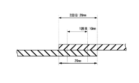
- the joint portion is a portion where the end portions of two adjacent sheets of raw fabric are in contact with each other, and indicates a portion whose thickness is 101% or more with respect to the thickness of the raw fabric.
- the thickness of the joint is typically preferably less than 200%, more preferably 150% or less, of the thickness of the raw fabric.
- the joints are typically welds formed by overlapping the widthwise ends of the raw materials to be joined together and welding the overlapping portions.
- the thermoplastic resin melts in the overlapping portion, and a part of the molten thermoplastic resin is extruded to the outside of the overlapping portion, and the thickness of the overlapping portion is thin The nearby part becomes thicker. Therefore, the joint is often formed wider than the overlapping portion.
- the width of the bonding portion is preferably 1 to 40 mm, more preferably 1 to 8 mm, still more preferably 1 to 5 mm, and particularly preferably 1 to 3 mm. If the width of the bonding portion is 40 mm or less, even if the bonding body shrinks due to heat applied to the bonding body, the width of the bonding portion is narrow, and the dimensional change of the bonding portion is relatively small. It is hard to produce wrinkles in a process. In particular, even if the joint is damaged when transported or fixed to the frame if it is 8 mm or less, since the width of the joint is narrow, the number of scratches on the joint is relatively small, and the scratches are less noticeable. Therefore, the appearance of the bonded body is unlikely to deteriorate, and the yield is also less likely to decrease.
- the tensile breaking strength of a junction part is excellent in the width of a junction part being 1 mm or more.
- the thickness of the raw fabric and the width of the joint in the joined body are measured by the following measurement method.
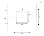
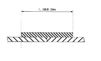
- the bonded body 1 is cut out into a square of 20 cm ⁇ 20 cm so that the bonding portion 1a for bonding the adjacent raw fabric 3 passes through the center of the TD at an arbitrary position of MD. Get The position of the joint 1a can be visually confirmed.
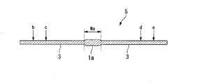
- the TD cross section is observed with an optical microscope at a position 10 cm inward from one outer edge of the MD of Sample 5, and as shown in FIG. 2, positions b, e and 4 cm at 2 cm inward from both outer edges of the TD cross section
- the thickness of the sample 5 is measured at the positions c and d (four places in total), and the average value of them is used as the thickness of the original fabric 3.
- the TD cross section is observed with an optical microscope at a position 10 cm inward from one outer edge of the MD of sample 5, and as shown in FIG.
- the width W a of (junction 1a) is determined.
- the width W a of the portion whose thickness is 101% or more of the thickness of the original 3 Ask for The average value of their widths W a is taken as the width of the joint 1 a.
- the tensile breaking strength of the joint portion is preferably 50% or more, more preferably 60% or more, and particularly preferably 80% or more of the tensile breaking strength of the raw fabric.
- the abrasion resistance of a junction and the dimensional stability are more excellent in tensile fracture strength of a junction being below the above-mentioned upper limit.
- the upper limit of the tensile breaking strength of the joint is not particularly limited, and may be 100%.
- the Rz on the surface of the bonding portion is preferably 15 ⁇ m or less, more preferably 5 ⁇ m or less, still more preferably 1 ⁇ m or less, and particularly preferably 0.7 ⁇ m or less.
- the abrasion resistance of a junction part is more excellent in Rz being below the above-mentioned upper limit. The smaller the Rz of the surface of the joint, the better, and it may be 0 ⁇ m.
- the raw fabric is made of a thermoplastic resin film.
- the thermoplastic resin film contains a thermoplastic resin.
- a thermoplastic resin amorphous resin and crystalline resin are mentioned. Examples of amorphous resins include polystyrene, polyvinyl chloride, polycarbonate, polymethyl methacrylate and the like.
- the crystalline resin may, for example, be a fluorine resin, a polyester resin or a polyolefin resin.
- ethylene-tetrafluoroethylene copolymer (hereinafter referred to as "ETFE"), perfluoro (alkyl vinyl ether) -tetrafluoroethylene copolymer (hereinafter referred to also as “PFA”), hexafluoropropylene -Tetrafluoroethylene copolymer (hereinafter also referred to as "FEP”), chlorotrifluoroethylene polymer (hereinafter referred to as "PCTFE”), vinyl fluoride polymer (hereinafter referred to also as "PVDF”) , Vinylidene fluoride polymer (hereinafter also referred to as "PVF”), vinylidene fluoride-hexafluoropropylene copolymer, tetrafluoroethylene-hexafluoropropylene-vinylidene fluoride copolymer, tetrafluoroethylene-propylene copolymer Combined, tetrafluoroethylene-prop
- polyester resin examples include polyethylene terephthalate resin, polybutylene terephthalate resin, and polylactic acid resin.
- polyolefin resin examples include polyethylene, ethylene- ⁇ -olefin copolymer, ethylene-vinyl acetate copolymer, ethylene-vinyl alcohol copolymer, polypropylene, ethylene-propylene copolymer and the like. Each of these polyolefin resins may further have other units.
- thermoplastic resin As a thermoplastic resin, a crystalline resin is preferable in that it is excellent in scratch resistance, chemical resistance and the like, and high strength can be easily obtained by stretching and the like. That is, it is preferable that a thermoplastic resin film is a film of crystalline resin. Among crystalline resins, fluorine resins are preferable in terms of excellent weather resistance and chemical resistance. That is, it is preferable that the thermoplastic resin film is a fluorine resin film.
- fluorine resins at least one selected from the group consisting of ETFE, PFA, FEP, PCTFE, PVDF and PVF is preferable in terms of excellent weatherability, specific gravity and cost, and from the group consisting of ETFE, PFA and FEP At least one selected is more preferable, and ETFE is particularly preferable.
- thermoplastic resin film may further contain other components other than the thermoplastic resin, as necessary.
- Other components include flame retardants, UV absorbers, UV blockers, fillers, pigments and the like.
- Rz of the surface of the thermoplastic resin film is typically 5 ⁇ m or less, but it is not limited to the above when embossing or the like is performed.
- the thickness of the thermoplastic resin film is typically 10 to 1,000 ⁇ m.
- the width of the thermoplastic resin film is typically 0.5 to 3 m.
- the root mean square height (hereinafter referred to as “root mean square height” of the surface undulation shape measured at a position 50 mm outward from the outer edge in the width direction of the joint portion joining adjacent raw materials of the joined body of the present invention (It is also described as “50 mm from the outer edge”) is 0.5 mm or less, preferably 0.45 mm or less, and particularly preferably 0.40 mm or less.
- the root mean square height (50 mm from the outer edge) is equal to or less than the upper limit value, the scratch resistance of the joined body is excellent.
- the “root mean square height of the surface undulation shape” is an index indicating the size of the wrinkles, and is measured by the following measurement method.
- the root mean square height (50 mm from the outer edge) becomes large.
- the root-mean-square height (50 mm from the outer edge) is 0 by setting the temperature measured by a thermocouple placed on the surface of the raw fabric at a position 50 mm outward from the outer edge in the width direction of the welding target area It can be less than .5 mm.
- FIG. 3 is a view schematically showing a surface undulation shape obtained by geometrically transforming pixel coordinates of a photographed image.
- root mean square height (1 mm from the outer edge) of the surface undulation shape measured at a position 1 mm outward from the outer edge of the joint in the width direction of the joint of the present invention.
- 0.5 mm or less is preferable and 0.45 mm or less is especially preferable.
- the root mean square height (1 mm from the outer edge) is preferably as small as possible, and may be 0 mm.
- the root mean square height (1 mm from the outer edge) tends to increase if the heat is applied to the area other than the welding target area of the raw material.
- the root-mean-square height (1 mm from the outer edge) is 0 by setting the temperature measured by a thermocouple placed on the surface of the raw fabric at a position 50 mm outward from the outer edge in the width direction of the welding target area It can be less than .5 mm.
- Root-mean-square height of surface undulation shape (hereinafter, also referred to as “root-mean-square height (50 mm from center)” of the bonded structure of the present invention measured at a position 50 mm outward from the center in the width direction of the bonding portion ) Is preferably 0.5 mm or less.
- the scratch resistance of the joined body is more excellent.
- the root mean square height (50 mm from the center) becomes large. Also, the wider the junction, the larger the root mean square height (50 mm from the center) tends to be.
- the temperature measured by a thermocouple placed on the surface of the raw fabric at a position 50 mm outward from the outer edge in the width direction of the region to be welded is 40 ° C. or less, and the width of the joint is 8 mm or less.
- the height (50 mm from the center) can be made 0.5 mm or less.
- 25 MPa or more is preferable, 35 MPa or more is more preferable, and 45 MPa or more is especially preferable. It can be used for the use by which the strength of a joined object is required as tensile rupture strength is more than the above-mentioned lower limit, for example, a film structure use.
- the upper limit of the tensile breaking strength of the joined body is not particularly limited, and is, for example, 60 MPa.
- the bonded body of the present invention can be produced by the method for producing a bonded body of the present invention described later.
- the width of the joint can be adjusted by the overlapping width of the two original rolls and the width of the target area to be heated and pressed. The larger the overlap width, the wider the joint.
- the overlapping width is smaller than the width of the target area, and the maximum width of the target area substantially matches the width of the joint.
- the overlapping width at the time of obtaining a bonded body having a width of 1 to 8 mm at the bonding portion is preferably 0 to 5 mm, and particularly preferably more than 0 mm and 5 mm or less.
- the method of producing the joined body of the present invention is not limited to this.
- the root mean square height of the surface undulation shape at a position of 50 mm on the outer side from the outer edge in the width direction of the bonded portion is 0.5 mm or less, it has excellent scratch resistance.
- the larger the wrinkles in the vicinity of the bonding portion the larger the variation in the degree of crystallization of the raw fabric in the vicinity of the bonding portion.
- the portion with low crystallinity is easily scratched, and the presence of such a portion lowers the scratch resistance of the bonded body.
- the scuff resistance of the joined body is reduced due to the large wrinkles and the possibility of rubbing against other members.
- the root mean square height of the surface undulation shape at the position is 0.5 mm or less, the variation of the crystallinity in the vicinity of the bonded portion is small, and the scratch easily occurs. There are few parts. In addition, because the swell is small, it is difficult to rub with other members. Therefore, it is thought that it is excellent in abrasion resistance.
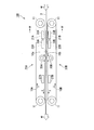
- FIG. 4 is a schematic configuration view of the welding device 100.
- FIG. 5 is a partial cross-sectional view showing a part of the IV-IV cross section in FIG.
- the welding apparatus 100 includes a pair of endless belts 10A and 10B and a pair of welds 20A and 20B.
- the endless band is a member in which the band is formed into an annular shape by joining end portions in the longitudinal direction.
- the pair of endless belts 10A and 10B are disposed vertically.
- the endless belts 10A and 10B are each rotatably supported in the first direction (the arrow X direction in FIG. 4) by the plurality of support rolls 11.
- the opposing portions of the pair of endless belts 10A and 10B that is, the portions of the endless belt 10A facing the endless belt 10B and the endless belt
- the portions of the strip 10B facing the endless strip 10A are arranged to travel forward. Traveling forward means traveling from the upstream side to the downstream side of the MD.
- traveling paths of two original rolls 3 are formed between the outer peripheral surfaces 10a and 10b of the opposing portions of the pair of endless belts 10A and 10B.
- the traveling path travels the two raw webs 3 with their widthwise ends overlapping or abutting each other.
- FIG. 5 shows an example in which the end portions in the width direction of two sheets of raw fabric 3 are overlapped and brought into contact with each other.
- the welding portion 20A is disposed inside the endless strip 10A at a position facing the traveling path.
- the welding unit 20A includes two heating units 21A and 23A (heating mechanisms), two cooling units 31A and 33A (first cooling mechanisms) disposed in the vicinity of the heating units 21A and 23A, and the heating units 21A and 23A. And a cooling unit 27A (second cooling mechanism) disposed on the downstream side of the pressing roll 25A.
- the heating unit 23A is disposed downstream of the heating unit 21A.
- the welding portion 20B is disposed inside the endless strip 10B at a position facing the traveling path.
- the welded portion 20B includes two heating units 21B and 23B (heating mechanisms), two cooling units 31B and 33B (first cooling mechanisms) disposed in the vicinity of the heating units 21B and 23B, and the heating units 21B and 23B. And a cooling unit 27B (second cooling mechanism) disposed on the downstream side of the pressing roll 25B.
- the heating unit 23B is disposed downstream of the heating unit 21B.
- the heating unit 21A and the heating unit 21B on the upstream side are disposed at opposing positions across the traveling path.
- the downstream side heating unit 23A and the heating unit 23B are disposed at opposing positions across the travel path. That is, two pairs of heating units 21A, 21B and 23A, 23B are provided in the middle of the traveling route along which the two original rolls travel, and the welding target regions of the two original rolls traveling along the traveling route are two stages from both sides. It can be heated.
- the four cooling units 31A, 31B, 33A, 33B are attached to the four heating units 21A, 21B, 23A, 23B, respectively, and other than the welding target areas of the two original rolls 3 traveling along the traveling path from each heating unit Heat transfer to the region of The pressing roll 25A and the pressing roll 25B are disposed at positions facing each other through the traveling path, and can press the welding target regions of the two upstream heated original sheets 3 traveling on the traveling path from both sides.
- the width of the pressure rolls 25A, 25B is equal to or less than the width of the endless strips 10A, 10B.
- the cooling unit 27A and the cooling unit 27B are disposed at opposing positions through the traveling path, and cool the welding target regions of the two heated and pressed original sheets traveling on the traveling path from both sides, It can be solidified.
- the cooling units 27A and 27B are, for example, water cooling plate type cooling units.
- FIG. 6 shows an example of endless belts that can be used as the endless belts 10A and 10B.
- the endless belt 10 shown in FIG. 6 includes an endless belt-like woven fabric layer 13 and a polytetrafluoroethylene (hereinafter also referred to as “PTFE”) layer 15 laminated on the outer peripheral surface of the woven fabric layer 13. .
- the PTFE layer 15 has a multilayer structure in which the PTFE coat layer 17 and the PTFE film layer 19 are laminated in order from the woven fabric layer 13 side.
- the Rz of the outer circumferential surface 10c of the endless strip 10, ie, the outer circumferential surface of the PTFE layer 15, is preferably 15 ⁇ m or less, more preferably 5 ⁇ m or less, still more preferably 1 ⁇ m or less, and particularly preferably 0.7 ⁇ m or less.
- the woven layer 13 has irregularities on the surface due to the fibers. Since the PTFE layer 15 is provided on the woven fabric layer 13, the outer peripheral surface 10c of the endless strip 10, that is, the surface in contact with the raw fabric 3 is flattened, and Rz is equal to or less than the upper limit.
- the width of the endless strip 10 is, for example, 1 to 10 cm.
- Rz of the outer peripheral surface 10c of the endless belt 10 that is, Rz of the outer peripheral surfaces 10a and 10b of the endless belts 10A and 10B is equal to or less than the upper limit
- the welding strength of the two original rolls 3 is excellent.
- the width of the welding target area that is, the width of the raw fabric welded portion (joint portion) where the raw fabrics are welded
- the tensile breaking strength of the raw fabric welded portion is 50% of the tensile breaking strength of the raw fabric 3. It can be more than%.
- the outer peripheral surfaces 10a and 10b of the endless belts 10A and 10B have the molten resin attached in the welding process, and the welding strength is rather reduced by the influence of the adhesive force. Since it is also possible to increase Rz is preferable.
- the width of the original welded portion is 1 to 8 mm, relatively the molten resin hardly adheres to the outer peripheral surfaces 10a and 10b, and the adhesion is also small.
- the attachment can also be suppressed by a cooling unit or the like. It is considered that the reduction of Rz effectively extends the overlapping portion of the raw fabric and also leads to the increase of the degree of crystallinity.
- glass fiber As a fiber which comprises the woven fabric layer 13, glass fiber, an aramid fiber, carbon fiber etc. are mentioned. These fibers may be used alone or in combination of two or more. Among the above, glass fiber is preferable in terms of excellent heat resistance and low cost.
- Examples of the type of weave of the woven fabric layer 13 include plain weave, twill weave, satin weave, and the like.
- the thickness of the woven fabric layer 13 is, for example, 10 to 100 ⁇ m.
- Rz of the surface of the woven fabric layer 13 is usually more than 15 ⁇ m and about 100 ⁇ m or less.
- the mass per unit area of the PTFE coat layer 17 (the applied amount of PTFE) is, for example, 50 to 150 g / m 2 .
- the thickness of the PTFE film layer 19 is preferably 10 to 200 ⁇ m, and particularly preferably 50 to 150 ⁇ m.
- the unevenness of the surface of the woven fabric layer 13 is hardly reflected on the outer peripheral surface of the PTFE film layer 19 when the thickness of the PTFE film layer 19 is not less than the lower limit, and the Rz of the outer peripheral surface 10c of the endless strip 10 is the upper limit. It is easy to become below.
- Rz of the surface of the original welded portion becomes equal to or less than the upper limit, and the abrasion resistance and tensile breaking strength of the original welded portion are excellent.
- the thickness of the PTFE film layer 19 is equal to or less than the upper limit value, the handling property is excellent.
- a PTFE dispersion containing PTFE and a dispersion medium is applied to the outer peripheral surface of an endless belt-like woven fabric (woven fabric layer 13) and dried to form a PTFE coated layer 17. And a method of laminating a PTFE film on the PTFE coat layer 17.
- the endless belt-like woven fabric is obtained by joining one end and the other end in the lengthwise direction of the belt-like woven fabric into an annular shape. Bonding of the woven fabric can be carried out by a conventional method. An existing endless belt-like woven fabric may be used.
- the PTFE dispersion may be a commercially available product.
- the drying method is, for example, heating at the boiling point or more of the dispersion medium.
- the Rz of the surface of the PTFE film is preferably 15 ⁇ m or less, and the more preferable range is as described above.
- the preferred thickness of the PTFE film is similar to the preferred thickness of the PTFE film layer 19. Examples of the method of laminating the PTFE film include thermal lamination, bonding using an adhesive layer, and the like.
- the PTFE coat layer 17 may be formed before making the belt-like woven fabric into an endless belt shape.
- the endless band used in the present invention is not limited to the endless band 10.
- the PTFE layer 15 may be composed of only the PTFE film layer 19 or may be composed of only the PTFE coat layer 17.
- the PTFE coat layer 17 may be provided on both sides of the woven fabric layer 13.
- a PTFE film layer 19 may be provided on both sides of the woven fabric layer 13.
- a part of the PTFE is impregnated into the woven fabric, and the surface of the PTFE coat layer 17 is roughened.
- Rz can be made equal to or less than the upper limit with only the PTFE coating layer 17, but the process is complicated and expensive. Therefore, the method of laminating a PTFE film is simple and preferable.
- the PTFE film may be laminated directly on the outer peripheral surface of the woven fabric layer 13 without forming the PTFE coat layer 17.
- the endless belt-like woven fabric layer 13 may be used as an endless belt as it is.
- the heating unit 21A is a heating plate type heating unit (heating plate type heating mechanism), and includes a heating plate 29 and a heater (not shown) for heating the heating plate.
- the heat plate 29 has a flat base portion 29a and a convex portion 29b protruding from the base portion 29a toward the endless strip 10A, and has a T-shaped TD cross section.
- the convex portion 29b has a distal end surface 29c, and a first side surface 29d and a second side surface 29e extending in the direction of the base 29a from each of the TD ends of the distal end surface 29c.
- the heat plate 29 is disposed with the tip end face 29c facing the traveling path.
- the end surface 29c contacts the inner peripheral surface of the endless belt 10A, and when the heating plate 29 is heated to an arbitrary temperature by the heater, the portion in contact with the end surface 29c of the endless belt 10A is heated, By this, the welding target area of the raw fabric 3 traveling on the traveling route is heated.
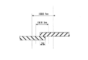
- Width of the end surface 29c is the same as the width W 1 of the two raw 3 of the welding target area.
- the width W 1 of the welding target area is typically wide relative to the overlapping width W 2 of the two original webs 3. Accordingly, the width in the TD of the end face 29c is also typically wide relative to the overlapping width W2 of the two original rolls 3.
- the other heating units 21B, 23A, and 23B are also hot plate type heating units, and have the same configuration as that of the heating unit 21A.
- the width of the end surface 29c of the upstream heating units 21A and 21B and the width of the end surface 29c of the downstream heating units 23A and 23B may be the same or different.
- the width of the end surface 29c of the heating units 21A and 21B may be narrower than the width of the end surface 29c of the heating units 23A and 23B.
- the widest width among the width of the end surface 29c of the heating units 21A and 21B and the width of the end surface 29c of the heating units 23A and 23B is the width of the original welded portion of the obtained bonded body.
- the cooling unit 31A is a water cooling plate type cooling unit (water cooling mechanism) including a pair of water cooling plates 35 and 37 disposed on both sides of the heating unit 21A in the TD.
- One water-cooling plate 35 has an L-shaped TD cross section, and is disposed on the first side face 29 d side (left side in FIG. 5) of the convex portion 29 b of the heat plate 29 with a gap between the water plate and the heat plate 29.
- the water cooling plate 35 covers the surface of the base portion 29a on the endless belt 10A side and the side surface of the base 29a on the first side surface 29d side and the first side surface 29d.
- the other water cooling plate 37 has a TD cross section that is an L-shape symmetrical with the water cooling plate 35, and on the second side surface 29e side (right side in FIG. 5) of the convex portion 29b of the heating plate 29 Spaced apart.
- the water cooling plate 37 covers the surface of the base portion 29a on the endless belt 10A side and the side surface of the base 29a on the second side surface 29e side and the second side surface 29e.
- the water cooling plates 35 and 37 for example, those having a configuration using a chiller can be mentioned.
- the cooling unit 31A by cooling the atmosphere between the heat plate 29 and the endless strip 10A with the water cooling plates 35, 37, the heat radiated from the surface other than the tip end surface 29c of the heat plate 29 is It can be transmitted to a region other than the welding target region of the raw fabric 3 and can be suppressed from increasing the temperature of the raw fabric 3.
- the water cooling plates 35 and 37 are arranged such that the tip end portions of the convex portions 29b of the heat plate 29 project to the endless belt 10A side more than the surfaces 35a and 37a of the water cooling plates 35 and 37 on the endless belt 10A side. Be done.
- the distance between the first side surface 29d of the heat plate 29 and the water cooling plates 35 and 37 is preferably 0.1 to 10 mm, and particularly preferably 0.5 to 5 mm.
- the difference between the surfaces 35a, 37a of the water cooling plates 35, 37 on the endless belt 10A side and the end surface 29c of the convex portion 29b is preferably 0.1 to 10 mm, particularly preferably 0.5 to 5 mm.
- the difference is less than the upper limit value, the effect of suppressing heat propagation to a region other than the welding target region is more excellent, and when it is more than the lower limit value, physical contact with the endless strip is avoided. The wear of the endless band is suppressed and the durability is excellent.
- the other cooling units 31B, 33A, 33B also have the same configuration as the cooling unit 31A.
- the pair of endless strip-shaped members 10A and 10B is rotated so that the portions facing each other travel forward.
- the two raw materials 3 made of a thermoplastic resin film face each other of the pair of endless belts 10A and 10B.
- a pair of heating units disposed on the upper and lower sides of the traveling route, including a portion where two original rolls 3 contact each other while traveling along the traveling route formed between the outer peripheral surfaces 10a and 10b of the part At both 21A and 21B, heating is performed from both sides via the endless belts 10A and 10B to fuse them (first heating step).
- the regions to be welded are heated and fused from both sides via the endless belts 10A and 10B by the pair of heating units 23A and 23B disposed above and below the traveling path (second heating step).
- the regions to be welded are pressed from both sides by pressure rolls 25A and 25B arranged above and below the traveling path, and pressed (pressure step).
- the regions to be welded are cooled from both sides by the cooling units 27A and 27B disposed above and below the traveling path and solidified (solidification step).
- the first heating step heat propagation from the heating units 21A and 21B to regions other than the welding target region of the two original rolls 3 (hereinafter, also referred to as "other regions") by the cooling units 31A and 31B.
- the temperature measured by a thermocouple disposed on the surface of the original 3 at a position 50 mm outward from the outer edge in the width direction of the welding target area is set to 40 ° C. or less.
- heat propagation from the heating units 23A and 23B to the other area of the two original rolls 3 is suppressed by the cooling units 33A and 33B, and the outer edge of the welding target area in the width direction is outward
- the temperature measured by the thermocouple placed on the surface of the raw fabric 3 at the position of 50 mm is 40 ° C. or less.
- the above-mentioned steps are repeated using the obtained conjugate in place of either one or both of the two base rolls 3.
- a joined body in which three or more original rolls 3 are joined is obtained.
- the obtained bonded body may be subjected to treatments such as corona treatment and dripping treatment, if necessary.
- the area to be welded after solidification is also referred to as an original welded area.
- the original welded portion may be a joint.
- at least a part of the raw fabric welded portion has a thickness of 101% or more of the thickness of the raw fabric, that is, a joint .
- the thickness of the raw fabric welded portion is less than 100% of the thickness of the raw fabric.
- the rotation speed of the endless belts 10A and 10B is, for example, 0.5 to 10 m / min, preferably 1.0 to 9.0 m / min, and more preferably Is 2.0 to 8.0 m / min. If it is in the said range, there exists a tendency for the tensile breaking strength of a raw material welding part to be excellent.
- the overlapping width of the two raw sheets is preferably 0 to 40 mm, more preferably 0 to 8 mm, still more preferably 0 mm to 8 mm or less, particularly preferably 1 to 7 mm, and most preferably 1 to 3 mm.
- the overlapping width of 0 mm indicates that the two raw webs are caused to travel while the ends in the width direction are in contact with each other. That the overlapping width is more than 0 mm indicates that the two raw webs are caused to travel with the widthwise end portions overlapped with each other.
- the overlapping width is equal to or less than the upper limit value, the width of the raw wire welded portion (joined portion) is narrow, so the amount of dimensional change of the raw wire welded portion is relatively small, and wrinkles in the post process hardly occur.
- the size is 8 mm or less, even if the original welded portion is damaged during transportation or fixing to the frame, the number of scratches on the original welded portion is relatively small because the width of the original welded portion is narrow. The wound is inconspicuous. Therefore, the appearance of the bonded body is unlikely to deteriorate, and the yield is also less likely to decrease.
- the overlapping width is 1 mm or more, the tensile breaking strength of the joint is excellent.
- the heating temperature in the first heating step and the second heating step is preferably (T-20) ° C. or more and (T + 20) ° C. or less (T ⁇ 10) ° C. or more and (T + 10) ° C. or less are more preferable, and (T ⁇ 5) ° C. or more and (T + 5) ° C. or less are particularly preferable.
- the pressure at the time of pressing in the first heating step and the second heating step is not particularly limited, and may be, for example, 0.1 to 0.5 MPa.
- the heating temperature and pressure in each heating step may be the same or different.
- the temperature measured by the thermocouple disposed on the surface of the raw fabric 3 at a position 50 mm outward from the outer edge in the width direction of the welding target regions of the two raw fabrics 3 is 40 ° C. or less, preferably 35 ° C. or less, particularly preferably 30 ° C. or less. If the temperature is equal to or less than the upper limit value, the tensile breaking strength of the raw welded portion can be 50% or more of the tensile breaking strength of the raw fabric even if the overlapping width of the two raw fabrics 3 is narrow.
- the lower limit of the temperature is not particularly limited, and is, for example, 10 ° C.
- the pressure at the time of pressing in the pressing step is preferably 0.1 to 5 MPa, and particularly preferably 0.5 to 2.5 MPa.
- the temperature at the time of pressing in the pressing step that is, the surface temperature of the pressing rolls 25A and 25B is not particularly limited, and is 25 ° C., for example.
- the cooling in the solidification step is performed so that the temperature measured by the thermocouple disposed on the surface of the raw fabric 3 at a position 50 mm outward from the outer edge in the width direction of the welding target area after cooling becomes 10 to 40 ° C.
- the reaction is preferably carried out at 15 to 35.degree. C., particularly preferably at 20 to 30.degree.
- the raw film 3 is placed 50 mm outward from the outer edge of the width direction of the welding target area of the two raw materials 3 Since the ambient temperature in the vicinity, which is measured by the thermocouple disposed on the surface of the above, is made equal to or lower than the upper limit value, the occurrence of wrinkles can be suppressed.
- the outer circumferential surface of the endless belts 10A and 10B is pressed against the surface of the heated welding target area.
- the temperature measured by the thermocouple disposed on the surface of the raw fabric 3 at a position 50 mm outward from the outer edge in the width direction of the target region is set to the upper limit value or less. Heat propagation to the other region of the original fabric 3 is sufficiently suppressed, and orientation relaxation in the other region is suppressed. Therefore, a bonded body with few wrinkles is obtained. In addition, variations in the degree of crystallinity in the vicinity of the bonding portion can also be suppressed.
- the raw fabric 3 When the target area is at a high temperature by heating, the raw fabric 3 is easily attached to the outer peripheral surface of the endless belts 10A and 10B. When this adhesive force is high, a part of the raw fabric 3 adheres to the endless belts 10A and 10B, so that a part of the raw fabric 3 is dropped to cause unevenness, or peeling occurs in a part of the joint. It becomes a cause. In addition, the raw fabric 3 is locally pulled and is likely to be distorted, which may cause wrinkles. In the above manufacturing method, when the welding target area is narrow, for example, 8 mm or less, the adhesion generated between the outer peripheral surface of the endless belts 10A and 10B and the raw fabric 3 can be suppressed low.
- the raw fabric 3 is less likely to adhere to the endless belts 10A and 10B.
- wrinkles are less likely to occur.
- the manufacturing method of the joined body of the present invention is not limited to the method using the welding device 100 of the illustrated example.
- the water cooling plate type cooling mechanism cooling units 31A, 31B, 33A, 33B
- another water cooling mechanism may be used.
- a wind cooling mechanism may be used.
- the heat propagation to the other area can be suppressed by sending an air flow of an arbitrary temperature to the atmosphere between the heating units 21A, 21B, 23A, 23B and the endless belts 10A, 10B.
- welding part 20A, 20B was provided with two heating mechanisms (heating unit 21A, 21B, heating unit 23A, 23B), respectively and the example which heats a welding object area
- the heating mechanism may be one or three or more, and the region to be welded may be heated in one or more stages.
- Example 1 is an example, and examples 2 to 5 are comparative examples. The evaluation methods and materials used in each example are shown below.
- Area camera (resolution 0.08 mm, shutter speed 10 ms, F-number F16) installed at a position 250 mm outward in the width direction and 25 mm upward in the height direction from the irradiation unit (the part irradiated with the laser light of the assembly)
- the image projected on the irradiation unit was taken at a focal distance of 55 mm, horizontally in the widthwise direction of the joint, with the irradiation unit as the focus position.
- the wave shape of the image taken was geometrically transformed to obtain the surface wave shape. In geometric transformation, each of 710 pixel coordinates was converted into mm coordinates by 0.08 (resolution).
- the standard deviation (mm) in the height direction is calculated by the above equation 1
- the root mean square height was taken.
- the root-mean-square height was determined in the same manner as described above for each of the positions 1 mm outward from the outer edge in the width direction of the joint of the bonded body and 50 mm outward from the center in the width direction of the joint. In addition, when welding itself was impossible, it described as "x.”
- ETFE film 100 ⁇ m thick ETFE film (melting point: about 270 ° C.).
- Endless strip 1 Endless strip having the configuration shown in FIG. 6 (woven fabric layer: woven glass fiber, plain weave, thickness of PTFE film layer: 100 ⁇ m, Rz of outer peripheral surface: 0.63 ⁇ m, arithmetic average roughness of outer peripheral surface) Ra: 0.1 ⁇ m).
- Example 1 Using the welding apparatus 100 having the configuration shown in FIGS. 4 to 5, a joined body was manufactured in the following procedure.
- the endless strip 1 was used as the endless strips 10A and 10B.
- the width of the tip surface of the first-stage heating units 21A and 21B is 3 mm, and the width of the tip surface of the second-stage heating units 23A and 23B is 5 mm.
- the end portions of two ETFE films (250 mm in width) are overlapped at an overlapping width of 1 mm, and the outer peripheral surface 10a of opposing portions of a pair of endless endless belts 10A and 10B is rotated.
- the traveling route formed between 10b was run.
- the heating unit 21A, 21B in the first stage and the heating unit 23A, 23B in the second stage sequentially heat from both sides, press from both sides with the pressure rolls 25A, 25B, and cool from both sides in the cooling units 27A, 27B. And obtained a conjugate.
- the cooling units 31A, 31B, 33A, 33B suppressed the heat propagation from each heating unit to the other region of the two original rolls.
- the rotation speed of the endless belts 10A and 10B that is, the transport speed of the raw fabric was 2 m / min, 5 m / min, or 8 m / min.
- the heating conditions in the heating units 21A and 21B were a heating temperature of 270 ° C., 275 ° C. or 280 ° C., and a pressure of 0 MPa.
- the heating conditions in the heating units 23A and 23B were the same as the heating units 21A and 21B except that the pressure was 0.1 MPa.
- the pressing conditions of the pressing rolls 25A and 25B were a temperature of 25 ° C. and a pressure of 2.5 MPa. In the cooling by the cooling units 27A and 27B, the surface temperature of the target area was set to 30.degree.
- the cooling by the cooling units 31A, 31B, 33A, 33B is a thermoelectric element disposed on the surface of the raw fabric 3 at a position 50 mm outward from the outer edge in the width direction of the target area at the time of heating in the first heating step and the second heating step.
- the temperature measured by the pair was made to be the temperature shown in Table 1.
- a thermocouple a data logger GL220 manufactured by GLARHTEC was used.
- the width of the bonded portion of the obtained bonded body was 3.9 mm, and the thickness of the bonded portion was 120 ⁇ m (120% of the original thickness).
- Example 2 In the welding apparatus 100, the cooling units 31A, 31B, 33A, and 33B were removed, and the heat propagation from each heating unit to the other area of the two original rolls was not suppressed, the first-stage heating units 21A and 21B
- the width of the tip surface (the width of the first heating area) is 25 mm
- the width of the tip surface of the second heating unit 23A, 23B (the width of the second heating area) is 30 mm, and As shown in FIG.
- Example 8 the end of an ETFE film (250 mm wide) is overlapped at an overlapping width of 20 mm, and an ETFE film of 30 mm wide is overlapped on the overlapping portion so as to straddle the overlapping portion, A joint was manufactured in the same manner as Example 1 except that the vehicle was run.
- the width of the bonded portion of the obtained bonded body was 28.6 mm, and the thickness of the bonded portion was 280 ⁇ m (280% of the original thickness).
- Example 3 The width of the tip surface of the first stage heating units 21A and 21B (the width of the area heated to the first time) is 10 mm, the width of the tip surface of the second stage heating units 23A and 23B (the width of the area heated to the second time ) was 20 mm, and as shown in FIG. 9, a joined body was produced in the same manner as in Example 2 except that an ETFE film of 30 mm in width was not superposed on the overlapping portion of two ETFE films.
- the width of the bonded portion of the obtained bonded body was 18.9 mm, and the thickness of the bonded portion was 170 ⁇ m (170% of the original thickness).
- Example 4 The width of the tip surface of the first-stage heating unit 21A, 21B (the width of the area to be heated at the first time) and the width of the tip surface of the second-stage heating unit 23A, 23B (the width of the area to be heated at the second time)
- a bonded body was manufactured in the same manner as in Example 2 except that the sizes were respectively 30 mm, and as shown in FIG. 10, the end portions of the two ETFE films were butted without overlapping.
- the 30 mm wide ETFE film was placed so that the center position in the width direction coincided with the butting position of the two ETFE films.
- the width of the bonded portion of the obtained bonded body was 29.1 mm, and the thickness of the bonded portion was 180 ⁇ m (180% of the original thickness).
- Example 5 In the welding apparatus 100, the joined body is removed in the same manner as in Example 1 except that the cooling units 31A, 31B, 33A, 33B are removed, and the heat propagation from each heating unit to the other regions of the two original rolls is not suppressed. Manufactured.
- the width of the bonded portion of the obtained bonded body was 3.9 mm, and the thickness of the bonded portion was 130 ⁇ m (130% of the original thickness).
- the root mean square height of the surface undulation shape at positions 50 mm and 1 mm outward from the widthwise outer edge of the joint of the joined body obtained in Examples 1 to 5 and 50 mm outside from the center of the widthwise joint of the joint Is shown in Table 1.
- the bonded structure of Example 1 has a root mean square height of 0.5 mm at a position 50 mm and 1 mm outward from the outer edge in the width direction of the joint and 50 mm outward from the center in the width direction of the joint. It was below and there were few wrinkles.
- the joined body of Examples 2 to 5 in which the temperature measured by the thermocouple disposed on the surface of the raw fabric at a position 50 mm outward from the outer edge in the width direction of the target area during heating of the target area was over 40 ° C.
- the root mean square height at a position of 50 mm outside the widthwise outer edge of the joint all exceeded 0.5 mm, and the wrinkles were large.
- the conjugate of the present invention can be used as a film for a membrane structure (for example, an outer covering film for a membrane structure) or as an agricultural film (for example, a house coating film for agriculture).
- the membrane structure is a structure such as a roof using a film, an outer wall, and a facility.
- the facilities include sports facilities (pools, gymnasiums, tennis courts, soccer fields, etc.), warehouses, gathering halls, exhibition halls, horticultural facilities (gardening houses, farming houses, etc.).
- the entire contents of the specification, claims, abstract and drawing of Japanese Patent Application No. 2017-226590 filed on November 27, 2017 are cited herein as the disclosure of the specification of the present invention, It is what it takes.
- W 1 assembly 1a joints, 3 raw, 5 samples, W a junction width, 10, 10A, 10B endless strip, 10a, 10b, the outer peripheral surface of 10c the endless strip, 11 the support rolls, 20A, 20B Welded part, 21A, 21B, 23A, 23B heating unit (heating mechanism), 25A, 25B pressing roll, 27A, 27B cooling unit (second cooling mechanism), 29 heating plate, 29a base, 29b convex part, 29c front end face , 29d first aspect, 29e second aspect, W 1 be welded region having a width, W 2 overlapping width, 30 cooling mechanism, 31A, 31B, 33A, 33B cooling unit (first cooling mechanism), 35 and 37 water-cooled plate , 100 welding equipment
Abstract
Provided is a joined body which exhibits excellent scratch resistance. This joined body, which is obtained by joining at least two sheets of a raw material comprising a thermoplastic resin film, is characterized in that the root mean square height of the wave shape of the surface measured in a position 50 mm outwards from the outer edge of a joined portion in the width direction, said joined portion being where adjacent sheets of the raw material are joined, is 0.5 mm or lower.
Description
本発明は、接合体、その製造方法及び溶着装置に関する。
The present invention relates to a joined body, a method of manufacturing the same, and a welding apparatus.
熱可塑性樹脂フィルムは、膜構造物用被覆材、農業用被覆材等の種々の用途に用いられる。熱可塑性樹脂フィルムの幅が必要な幅に満たない場合には、熱可塑性樹脂フィルムの幅方向の端部同士を接合し、接合体として使用される。
熱可塑性樹脂フィルムの接合方法としては、溶着法が工業的に多く用いられる(例えば特許文献1~3)。溶着法による接合は、例えば、2枚の熱可塑性樹脂フィルムを、幅方向の端部を重ね合わせた状態で挟んで走行させる一対の無端帯状体と、その走行経路に対向して設置され、2枚の熱可塑性樹脂フィルムの重なり部分を押圧しながら加熱する加熱機構とを備える溶着装置を用いて行われる。 Thermoplastic resin films are used in various applications such as coating materials for membrane structures and agricultural coating materials. When the width of the thermoplastic resin film is less than the required width, the end portions in the width direction of the thermoplastic resin film are bonded to each other and used as a bonded body.
As a method of bonding a thermoplastic resin film, a welding method is often used industrially (for example, Patent Documents 1 to 3). Bonding by welding is, for example, a pair of endless belts that run by sandwiching two thermoplastic resin films in a state in which the end portions in the width direction are overlapped, and installed opposite to the traveling path, It is carried out using a welding device provided with a heating mechanism which heats while pressing an overlapping portion of a sheet of thermoplastic resin film.
膜構造物用被覆資材や農業用被覆資材は、フレームに固定されて使用されることが多い。しかし、従来の接合体は、搬送時やフレームへの固定時にフレーム等と擦れて表面が傷付きやすい問題がある。接合体表面の傷は、外観不良及び歩留まりの低下を引き起こす。
Coating materials for membrane structures and agricultural coating materials are often fixed to a frame and used. However, the conventional bonded body has a problem that the surface is easily scratched by rubbing with the frame or the like during transportation or fixing to the frame. Scratches on the surface of the bonded body cause appearance defects and a reduction in yield.
本発明は、耐擦り傷性に優れた接合体を提供することを目的とする。
本発明は、熱可塑性樹脂フィルム同士を接合する際のシワの発生を抑制できる接合体の製造方法、並びに該製造方法に好適に用いられる溶着装置を提供することを他の目的とする。 An object of the present invention is to provide a conjugate excellent in scratch resistance.
Another object of the present invention is to provide a method of producing a joined body capable of suppressing the occurrence of wrinkles when joining thermoplastic resin films, and a welding apparatus suitably used for the production method.
本発明は、以下の〔1〕~〔15〕の構成を有する、接合体、その製造方法及び溶着装置を提供する。
〔1〕熱可塑性樹脂フィルムからなる少なくとも2枚の原反が接合された接合体であって、
隣り合う原反同士の接合部の幅方向の外縁から外側に50mmの位置で測定される表面うねり形状の二乗平均平方根高さが0.5mm以下であることを特徴とする接合体。
〔2〕前記接合部の幅方向の外縁から外側に1mmの位置で測定される表面うねり形状の二乗平均平方根高さが0.5mm以下である〔1〕の接合体。
〔3〕前記接合部の幅が1~40mmである〔1〕又は〔2〕の接合体。
〔4〕前記熱可塑性樹脂フィルムが結晶性樹脂のフィルムである〔1〕~〔3〕のいずれかの接合体。
〔5〕前記熱可塑性樹脂フィルムがフッ素樹脂のフィルムである〔1〕~〔4〕のいずれかの接合体。
〔6〕前記フッ素樹脂が、エチレン-テトラフルオロエチレン共重合体、ペルフルオロ(アルキルビニルエーテル)-テトラフルオロエチレン共重合体、ヘキサフルオロプロピレン-テトラフルオロエチレン共重合体、クロロトリフルオロエチレン重合体、ビニルフルオリド重合体、ビニリデンフルオリド重合体、ビニリデンフルオリド-ヘキサフルオロプロピレン共重合体、テトラフルオロエチレン-ヘキサフルオロプロピレン-ビニリデンフルオリド共重合体、テトラフルオロエチレン-プロピレン共重合体、テトラフルオロエチレン-ビニリデンフルオリド-プロピレン共重合体、エチレン-クロロトリフルオロエチレン共重合体及びプロピレン-クロロトリフルオロエチレン共重合体からなる群から選ばれる少なくとも1種である〔5〕の接合体。
〔7〕膜構造物用フィルムである〔1〕~〔6〕のいずれかの接合体。
〔8〕農業用フィルムである〔1〕~〔6〕のいずれかの接合体。
〔9〕一対の無端帯状体を、相対向する部分が往動走行するように回動させ、熱可塑性樹脂フィルムからなる2枚の原反を、各原反の幅方向の端部を互いに重ね合わせて又は突き合わせて接触させた状態で、前記一対の無端帯状体の前記相対向する部分の外周面の間に挟んで走行させ、前記2枚の原反が互いに接触する部分を含む溶着対象領域を両面から加熱及び押圧し、前記2枚の原反を溶着する工程を少なくとも1回行って、前記2枚の原反が少なくとも1回溶着された接合体を製造する方法であって、
前記溶着対象領域の加熱の際、前記溶着対象領域の幅方向の外縁から外側に50mmの位置で前記原反の表面に配置した熱電対で測定される温度を40℃以下にすることを特徴とする接合体の製造方法。
〔10〕前記2枚の原反の重なり幅が0~40mmである〔9〕の製造方法。
〔11〕前記熱可塑性樹脂フィルムが結晶性樹脂のフィルムである〔9〕又は〔10〕の製造方法。
〔12〕前記熱可塑性樹脂フィルムがフッ素樹脂のフィルムである〔9〕~〔11〕のいずれかの製造方法。
〔13〕前記2枚の原反が走行する走行経路の途中に少なくとも一対の熱板式加熱機構が設けられ、前記少なくとも一対の熱板式加熱機構により前記溶着対象領域を加熱するとともに、前記熱板式加熱機構から前記2枚の原反の溶着対象領域以外の領域への熱伝播を第1の冷却機構によって抑制する〔9〕~〔12〕のいずれかの製造方法。
〔14〕前記第1の冷却機構が、水冷機構又は風冷機構である〔13〕の製造方法。
〔15〕回動したときに、相対向する部分が往動走行するように配置された一対の無端帯状体と、一対の溶着部とを備え、
前記一対の無端帯状体の前記相対向する部分の外周面の間に、熱可塑性樹脂フィルムからなる2枚の原反を、各原反の幅方向の端部を互いに重ね合わせて又は突き合わせて接触させた状態で走行させる走行経路が形成され、前記一対の溶着部はそれぞれ、前記一対の無端帯状体の内側の、前記走行経路に対向する位置に配置され、
前記一対の溶着部はそれぞれ、少なくとも1つの熱板式加熱機構と、前記熱板式加熱機構の近傍に配置された第1の冷却機構と、前記熱板式加熱機構の下流側に配置された押圧ロールと、前記押圧ロールの下流側に配置された第2の冷却機構とを備え、
前記第1の冷却機構は、前記熱板式加熱機構から前記2枚の原反の対象領域以外の領域への熱伝播を抑制するように設けられることを特徴とする溶着装置。 The present invention provides a joined body, a method for producing the same, and a welding apparatus having the following constitutions [1] to [15].
[1] A joined body in which at least two sheets of a raw material comprising a thermoplastic resin film are joined,
A joined body characterized in that the root mean square height of the surface undulation shape measured at a position of 50 mm outside from the outer edge in the width direction of the joined portions of adjacent raw webs is 0.5 mm or less.
[2] The bonded body according to [1], wherein the root mean square height of the surface undulation shape measured at a position of 1 mm from the outer edge in the width direction of the bonded portion is 0.5 mm or less.
[3] The bonded body of [1] or [2], wherein the width of the bonding portion is 1 to 40 mm.
[4] The bonded body according to any one of [1] to [3], wherein the thermoplastic resin film is a film of a crystalline resin.
[5] The bonded body according to any one of [1] to [4], wherein the thermoplastic resin film is a fluorine resin film.
[6] The above-mentioned fluorine resin is ethylene-tetrafluoroethylene copolymer, perfluoro (alkyl vinyl ether) -tetrafluoroethylene copolymer, hexafluoropropylene-tetrafluoroethylene copolymer, chlorotrifluoroethylene polymer, vinyl fluoride Polymer, vinylidene fluoride polymer, vinylidene fluoride-hexafluoropropylene copolymer, tetrafluoroethylene-hexafluoropropylene-vinylidene fluoride copolymer, tetrafluoroethylene-propylene copolymer, tetrafluoroethylene-vinylidene At least one member selected from the group consisting of a fluoride-propylene copolymer, an ethylene-chlorotrifluoroethylene copolymer, and a propylene-chlorotrifluoroethylene copolymer [ Conjugate].
[7] The bonded body of any one of [1] to [6], which is a film for a membrane structure.
[8] The bonded body according to any one of [1] to [6], which is an agricultural film.
[9] The pair of endless belts are rotated so that the opposing portions travel forward, and two original rolls made of thermoplastic resin film are overlapped with the end portions in the width direction of the respective raw rolls. A welding target area including a portion in which the two raw sheets are in contact with each other while being held between the outer peripheral surfaces of the opposing portions of the pair of endless bands in a state where they are brought together or in contact. A method of manufacturing a joined body in which the two sheets of raw fabric are welded at least once by performing heating and pressing from both sides and welding the two sheets of raw fabric at least once.
When heating the welding target area, the temperature measured by the thermocouple disposed on the surface of the raw fabric at a position 50 mm outward from the outer edge in the width direction of the welding target area is 40 ° C. or less. Method of producing a bonded body.
[10] The production method of [9], wherein the overlapping width of the two original rolls is 0 to 40 mm.
[11] The method for producing [9] or [10], wherein the thermoplastic resin film is a film of a crystalline resin.
[12] The process according to any one of [9] to [11], wherein the thermoplastic resin film is a fluororesin film.
[13] At least a pair of heating plate heating mechanisms are provided in the middle of a traveling path along which the two original rolls travel, and the welding target area is heated by the at least a pair of heating plates heating mechanisms. The method according to any one of [9] to [12], wherein the heat propagation from the mechanism to the region other than the region to be welded of the two sheets of raw fabric is suppressed by the first cooling mechanism.
[14] The method according to [13], wherein the first cooling mechanism is a water cooling mechanism or an air cooling mechanism.
[15] A pair of endless belts arranged so that the opposing parts travel forward when rotated, and a pair of welding parts,
Between the outer peripheral surfaces of the opposing portions of the pair of endless belts, two original rolls made of a thermoplastic resin film are brought into contact with each other by overlapping or abutting the end portions in the width direction of the respective raw rolls A travel path is provided for traveling in a state where the pair of welded portions are disposed at positions inside the pair of endless belts, the positions facing the travel path,
Each of the pair of welding parts includes at least one hot plate heating mechanism, a first cooling mechanism disposed in the vicinity of the hot plate heating mechanism, and a pressing roll disposed downstream of the hot plate heating mechanism. A second cooling mechanism disposed downstream of the pressing roll;
The first cooling mechanism is provided so as to suppress heat propagation from the heat plate type heating mechanism to a region other than the target region of the two original rolls.
本発明の接合体は、耐擦り傷性に優れる。
本発明の接合体の製造方法によれば、熱可塑性樹脂フィルム同士を接合する際のシワの発生を抑制できる。
本発明の溶着装置は、前記接合体の製造方法に好適に用いられる。 The bonded body of the present invention is excellent in abrasion resistance.
According to the method for producing a joined body of the present invention, the occurrence of wrinkles when joining the thermoplastic resin films can be suppressed.
The welding apparatus of the present invention is suitably used for the method of manufacturing the joined body.
本明細書における以下の用語の意味は、以下の通りである。
「引張破断強度」とは、JIS K6251:2010(ISO 37)に規定されるダンベル状5号形のサンプルについて、JIS K7127:1999に基づき、試験速度200mm/分にて測定される引張破壊応力(MPa)である。接合体の接合部の引張破断強度の測定において、サンプルは、サンプルの長さ方向が接合体のTDと一致し、且つサンプルの長さ方向の中央部を接合部が通るように接合体から切り出したものを使用する。
「融点」とは、示差走査熱量測定(DSC)法で測定した融解ピークの最大値に対応する温度を意味する。
「最大高さ粗さRz」とは、ISO4287:1997,Amd.1:2009(JIS B0601:2001)に基づき測定される値である。最大高さ粗さを求める際の、粗さ曲線用の基準長さlr(カットオフ値λc)は0.8mmとする。なお、本明細書においては、単に「Rz」と記すことがある。
「原反」とは、溶着等の後加工をする前のフィルムである。原反は、ロール状に巻き取られた長尺(帯状)のフィルムでも枚葉のフィルムでもよい。
「溶着対象領域」とは、接合体の製造時に原反同士が溶着される領域、つまり加熱及び押圧される領域である。
本明細書においては、流れ方向を「MD」(Machine Direction)とも記し、MDと直交する方向を「TD」(Transverse Direction)とも記す。MDは原反の長さ方向と一致する。また、MDは、典型的には接合時(溶着時)の原反の走行方向であり、接合部(原反溶着部)が延びる方向である。TDは、典型的には原反の幅方向及び接合部の幅方向と一致する。
図1、図2および図4~10における寸法比は、説明の便宜上、実際のものとは異なる。 The meanings of the following terms in the present specification are as follows.
The “tensile breaking strength” means the tensile breaking stress (tested at a test speed of 200 mm / minute based on JIS K7127: 1999) for the dumbbell-shaped No. 5 sample specified in JIS K6251: 2010 (ISO 37). MPa). In the measurement of the tensile breaking strength of the joint of the joined body, the sample is cut out of the joined body so that the longitudinal direction of the sample coincides with the TD of the joined body and the joined portion passes through the central portion in the longitudinal direction of the sample. Use the
By "melting point" is meant the temperature corresponding to the maximum of the melting peak as measured by differential scanning calorimetry (DSC).
“Maximum height roughness Rz” refers to ISO 4287: 1997, Amd. 1: It is a value measured based on 2009 (JIS B0601: 2001). The reference length lr (cutoff value λc) for the roughness curve in determining the maximum height roughness is 0.8 mm. In the present specification, it may be simply referred to as "Rz".
A "raw material" is a film before post-processing such as welding. The raw material may be a long (band-like) film wound into a roll or a sheet-like film.
A "welding object area | region" is an area | region where raw materials are welded at the time of manufacture of a joined body, ie, an area | region heated and pressed.
In the present specification, the flow direction is also described as "MD" (Machine Direction), and the direction orthogonal to the MD is also described as "TD" (Transverse Direction). MD coincides with the length direction of the raw fabric. Moreover, MD is a traveling direction of the original fabric at the time of joining (welding) typically, and is a direction in which a junction part (raw fabric welding part) is extended. TD typically coincides with the width direction of the original web and the width direction of the joint.
The dimensional ratios in FIGS. 1, 2 and 4 to 10 are different from actual ones for the convenience of description.
〔接合体〕
本発明の接合体は、熱可塑性樹脂フィルムからなる少なくとも2枚の原反が接合されたものであり、隣り合う原反同士を接合する接合部を有する。
本発明の接合体は、典型的には、2枚以上の原反が幅方向に沿って配置され、隣り合う原反の幅方向の端部同士が接合されたものである。原反は、長さを長くすることは容易であるが、幅を広くするには限界がある。原反を幅方向に2枚以上並べて接合することで、広幅かつ大面積にできる。
接合体を構成する原反の数は、所望の幅に応じて適宜選定でき、特に限定されないが、例えば2~10枚である。 [Bonded body]
The bonded body of the present invention is obtained by bonding at least two sheets of a raw material made of a thermoplastic resin film, and has a bonding portion for bonding adjacent raw materials.
The joined body of the present invention is typically one in which two or more original rolls are disposed along the width direction, and the end portions in the width direction of the adjacent original rolls are joined. Raw material is easy to lengthen, but there is a limit to widening. By arranging two or more sheets of raw material in the width direction and joining them, a wide area and a large area can be obtained.
The number of the raw fabric constituting the joined body can be appropriately selected according to the desired width and is not particularly limited, and is, for example, 2 to 10.
接合部とは、隣り合う2枚の原反の端部同士が接触した部分であって、厚さが原反の厚さに対して101%以上である部分を示す。接合部の厚さは典型的には、原反の厚さに対して200%未満が好ましく、150%以下がより好ましい。
The joint portion is a portion where the end portions of two adjacent sheets of raw fabric are in contact with each other, and indicates a portion whose thickness is 101% or more with respect to the thickness of the raw fabric. The thickness of the joint is typically preferably less than 200%, more preferably 150% or less, of the thickness of the raw fabric.
接合部は、典型的には、接合する原反の幅方向の端部を互いに重ね合わせ、その重なり部分を溶着させることにより形成された溶着部である。
本発明では溶着時に重なり部分を両面から押圧するため、重なり部分で熱可塑性樹脂が溶融し、溶融した熱可塑性樹脂の一部が重なり部分の外側に押し出され、重なり部分の厚さが薄く、その近傍の部分が厚くなる。したがって、接合部は、重なり部分よりも広幅で形成されることが多い。
接合体を製造する際に重なり部分がよく延ばされて接合部が形成されると、延伸により接合部の結晶化度が高まり、接合部の幅が狭くても充分な引張強度を有する接合体が得られやすい。そのため、接合部の厚さは薄い方が好ましい。 The joints are typically welds formed by overlapping the widthwise ends of the raw materials to be joined together and welding the overlapping portions.
In the present invention, since the overlapping portion is pressed from both sides at the time of welding, the thermoplastic resin melts in the overlapping portion, and a part of the molten thermoplastic resin is extruded to the outside of the overlapping portion, and the thickness of the overlapping portion is thin The nearby part becomes thicker. Therefore, the joint is often formed wider than the overlapping portion.
A joint having a sufficient tensile strength even when the width of the joint is narrow, when the joint is formed by extending the overlapping portion well when the joint is manufactured, and the degree of crystallization of the joint is increased by stretching. Is easy to obtain. Therefore, it is preferable that the thickness of the bonding portion be thin.
接合部の幅は、1~40mmが好ましく、1~8mmがより好ましく、1~5mmがさらに好ましく、1~3mmが特に好ましい。接合部の幅が40mm以下であると、接合体に熱がかかる等によって接合体が収縮しても、接合部の幅が狭いために接合部の寸法変化量が相対的に少なく、シワ(後工程でのシワ)が生じにくい。特に8mm以下であると、搬送時やフレームへの固定時に接合部に傷が付いても、接合部の幅が狭いために接合部の傷の数が相対的に少なく、その傷が目立ちにくい。そのため、接合体の外観が悪化しにくく、また歩留りも低下しにくい。接合部の幅が1mm以上であると、接合部の引張破断強度が優れる。
The width of the bonding portion is preferably 1 to 40 mm, more preferably 1 to 8 mm, still more preferably 1 to 5 mm, and particularly preferably 1 to 3 mm. If the width of the bonding portion is 40 mm or less, even if the bonding body shrinks due to heat applied to the bonding body, the width of the bonding portion is narrow, and the dimensional change of the bonding portion is relatively small. It is hard to produce wrinkles in a process. In particular, even if the joint is damaged when transported or fixed to the frame if it is 8 mm or less, since the width of the joint is narrow, the number of scratches on the joint is relatively small, and the scratches are less noticeable. Therefore, the appearance of the bonded body is unlikely to deteriorate, and the yield is also less likely to decrease. The tensile breaking strength of a junction part is excellent in the width of a junction part being 1 mm or more.
接合体における原反の厚さ及び接合部の幅は、以下の測定方法により測定される。
図1に示すように、接合体1を、MDの任意の位置で、隣り合う原反3同士を接合する接合部1aがTDの中央を通るように20cm×20cmの正方形状に切り出してサンプル5を得る。接合部1aの位置は目視で確認できる。
サンプル5のMDの一方の外縁から内側に10cmの位置で、光学顕微鏡によりTD断面を観察し、図2に示すように、TD断面の両方の外縁から内側に2cmの位置b,e及び4cmの位置c,d(合計4カ所)でサンプル5の厚さを測定し、それらの平均値を原反3の厚さとする。
サンプル5のMDの一方の外縁から内側に10cmの位置で、光学顕微鏡によりTD断面を観察し、図2に示すように、厚さが原反3の厚さに対して101%以上である部分(接合部1a)の幅Waを求める。サンプル5のMDの一方の外縁から他方の外縁に向かって5cm及び15cmの位置でもそれぞれ前記と同様にして、厚さが原反3の厚さに対して101%以上である部分の幅Waを求める。それらの幅Waの平均値を接合部1aの幅とする。 The thickness of the raw fabric and the width of the joint in the joined body are measured by the following measurement method.
As shown in FIG. 1, the bonded body 1 is cut out into a square of 20 cm × 20 cm so that thebonding portion 1a for bonding the adjacent raw fabric 3 passes through the center of the TD at an arbitrary position of MD. Get The position of the joint 1a can be visually confirmed.
The TD cross section is observed with an optical microscope at aposition 10 cm inward from one outer edge of the MD of Sample 5, and as shown in FIG. 2, positions b, e and 4 cm at 2 cm inward from both outer edges of the TD cross section The thickness of the sample 5 is measured at the positions c and d (four places in total), and the average value of them is used as the thickness of the original fabric 3.
The TD cross section is observed with an optical microscope at aposition 10 cm inward from one outer edge of the MD of sample 5, and as shown in FIG. The width W a of (junction 1a) is determined. In the same manner as above at the positions of 5 cm and 15 cm from one outer edge to the other outer edge of the sample 5 MD, the width W a of the portion whose thickness is 101% or more of the thickness of the original 3 Ask for The average value of their widths W a is taken as the width of the joint 1 a.
図1に示すように、接合体1を、MDの任意の位置で、隣り合う原反3同士を接合する接合部1aがTDの中央を通るように20cm×20cmの正方形状に切り出してサンプル5を得る。接合部1aの位置は目視で確認できる。
サンプル5のMDの一方の外縁から内側に10cmの位置で、光学顕微鏡によりTD断面を観察し、図2に示すように、TD断面の両方の外縁から内側に2cmの位置b,e及び4cmの位置c,d(合計4カ所)でサンプル5の厚さを測定し、それらの平均値を原反3の厚さとする。
サンプル5のMDの一方の外縁から内側に10cmの位置で、光学顕微鏡によりTD断面を観察し、図2に示すように、厚さが原反3の厚さに対して101%以上である部分(接合部1a)の幅Waを求める。サンプル5のMDの一方の外縁から他方の外縁に向かって5cm及び15cmの位置でもそれぞれ前記と同様にして、厚さが原反3の厚さに対して101%以上である部分の幅Waを求める。それらの幅Waの平均値を接合部1aの幅とする。 The thickness of the raw fabric and the width of the joint in the joined body are measured by the following measurement method.
As shown in FIG. 1, the bonded body 1 is cut out into a square of 20 cm × 20 cm so that the
The TD cross section is observed with an optical microscope at a
The TD cross section is observed with an optical microscope at a
接合部の引張破断強度は、原反の引張破断強度の50%以上が好ましく、60%以上がより好ましく、80%以上が特に好ましい。接合部の引張破断強度が前記上限値以下であると、接合部の耐擦り傷性、寸法安定性がより優れる。接合部の引張破断強度の上限は特に限定されず、100%でもよい。
The tensile breaking strength of the joint portion is preferably 50% or more, more preferably 60% or more, and particularly preferably 80% or more of the tensile breaking strength of the raw fabric. The abrasion resistance of a junction and the dimensional stability are more excellent in tensile fracture strength of a junction being below the above-mentioned upper limit. The upper limit of the tensile breaking strength of the joint is not particularly limited, and may be 100%.
接合部表面のRzは、15μm以下が好ましく、5μm以下がより好ましく、1μm以下がさらに好ましく、0.7μm以下が特に好ましい。Rzが前記上限値以下であると、接合部の耐擦り傷性がより優れる。
接合部表面のRzは小さいほど好ましく、0μmでもよい。 The Rz on the surface of the bonding portion is preferably 15 μm or less, more preferably 5 μm or less, still more preferably 1 μm or less, and particularly preferably 0.7 μm or less. The abrasion resistance of a junction part is more excellent in Rz being below the above-mentioned upper limit.
The smaller the Rz of the surface of the joint, the better, and it may be 0 μm.
原反は熱可塑性樹脂フィルムからなる。
熱可塑性樹脂フィルムは、熱可塑性樹脂を含む。
熱可塑性樹脂としては、非晶性樹脂及び結晶性樹脂が挙げられる。
非晶性樹脂としては、ポリスチレン、ポリ塩化ビニル、ポリカーボネート、ポリメタクリル酸メチル等が挙げられる。
結晶性樹脂としては、フッ素樹脂、ポリエステル樹脂、ポリオレフィン樹脂等が挙げられる。 The raw fabric is made of a thermoplastic resin film.
The thermoplastic resin film contains a thermoplastic resin.
As a thermoplastic resin, amorphous resin and crystalline resin are mentioned.
Examples of amorphous resins include polystyrene, polyvinyl chloride, polycarbonate, polymethyl methacrylate and the like.
The crystalline resin may, for example, be a fluorine resin, a polyester resin or a polyolefin resin.
フッ素樹脂としては、エチレン-テトラフルオロエチレン共重合体(以下、「ETFE」とも記す。)、ペルフルオロ(アルキルビニルエーテル)-テトラフルオロエチレン共重合体(以下、「PFA」とも記す。)、ヘキサフルオロプロピレン-テトラフルオロエチレン共重合体(以下、「FEP」とも記す。)、クロロトリフルオロエチレン重合体(以下、「PCTFE」とも記す。)、ビニルフルオリド重合体(以下、「PVDF」とも記す。)、ビニリデンフルオリド重合体(以下、「PVF」とも記す。)、ビニリデンフルオリド-ヘキサフルオロプロピレン共重合体、テトラフルオロエチレン-ヘキサフルオロプロピレン-ビニリデンフルオリド共重合体、テトラフルオロエチレン-プロピレン共重合体、テトラフルオロエチレン-ビニリデンフルオリド-プロピレン共重合体、エチレン-クロロトリフルオロエチレン共重合体及びプロピレン-クロロトリフルオロエチレン共重合体等が挙げられる。これらのフッ素樹脂はそれぞれ、他の単位をさらに有してもよい。
As the fluorine resin, ethylene-tetrafluoroethylene copolymer (hereinafter referred to as "ETFE"), perfluoro (alkyl vinyl ether) -tetrafluoroethylene copolymer (hereinafter referred to also as "PFA"), hexafluoropropylene -Tetrafluoroethylene copolymer (hereinafter also referred to as "FEP"), chlorotrifluoroethylene polymer (hereinafter referred to as "PCTFE"), vinyl fluoride polymer (hereinafter referred to also as "PVDF") , Vinylidene fluoride polymer (hereinafter also referred to as "PVF"), vinylidene fluoride-hexafluoropropylene copolymer, tetrafluoroethylene-hexafluoropropylene-vinylidene fluoride copolymer, tetrafluoroethylene-propylene copolymer Combined, tetrafluoroethy Down - vinylidene fluoride - propylene copolymer, ethylene - chlorotrifluoroethylene copolymer and propylene - chlorotrifluoroethylene copolymer, and the like. Each of these fluororesins may further have other units.
ポリエステル樹脂としては、ポリエチレンテレフタレート樹脂、ポリブチレンテレフタレート樹脂、ポリ乳酸樹脂等が挙げられる。
ポリオレフィン樹脂としては、ポリエチレン、エチレン-αオレフィン共重合体、エチレン-ビニルアセテート共重合体、エチレン-ビニルアルコール共重合体、ポリプロピレン、エチレン-プロピレン共重合体等が挙げられる。これらのポリオレフィン樹脂はそれぞれ、他の単位をさらに有してもよい。 Examples of the polyester resin include polyethylene terephthalate resin, polybutylene terephthalate resin, and polylactic acid resin.
Examples of the polyolefin resin include polyethylene, ethylene-α-olefin copolymer, ethylene-vinyl acetate copolymer, ethylene-vinyl alcohol copolymer, polypropylene, ethylene-propylene copolymer and the like. Each of these polyolefin resins may further have other units.
熱可塑性樹脂としては、耐傷付き性、耐薬品性等に優れ、延伸等により高い強度が得られやすい点で、結晶性樹脂が好ましい。すなわち、熱可塑性樹脂フィルムが結晶性樹脂のフィルムであることが好ましい。
結晶性樹脂の中でも、耐候性、耐薬品性に優れる点で、フッ素樹脂が好ましい。すなわち、熱可塑性樹脂フィルムがフッ素樹脂のフィルムであることが好ましい。
フッ素樹脂の中でも、耐候性と比重、価格の面に優れる点で、ETFE、PFA、FEP、PCTFE、PVDF及びPVFからなる群から選ばれる少なくとも1種が好ましく、ETFE、PFA及びFEPからなる群から選ばれる少なくとも1種がより好ましく、ETFEが特に好ましい。 As a thermoplastic resin, a crystalline resin is preferable in that it is excellent in scratch resistance, chemical resistance and the like, and high strength can be easily obtained by stretching and the like. That is, it is preferable that a thermoplastic resin film is a film of crystalline resin.
Among crystalline resins, fluorine resins are preferable in terms of excellent weather resistance and chemical resistance. That is, it is preferable that the thermoplastic resin film is a fluorine resin film.
Among the fluorine resins, at least one selected from the group consisting of ETFE, PFA, FEP, PCTFE, PVDF and PVF is preferable in terms of excellent weatherability, specific gravity and cost, and from the group consisting of ETFE, PFA and FEP At least one selected is more preferable, and ETFE is particularly preferable.
熱可塑性樹脂フィルムは、必要に応じて、熱可塑性樹脂以外の他の成分をさらに含んでいてもよい。他の成分としては、難燃剤、紫外光吸収剤、紫外線遮断剤、フィラー、顔料等が挙げられる。
The thermoplastic resin film may further contain other components other than the thermoplastic resin, as necessary. Other components include flame retardants, UV absorbers, UV blockers, fillers, pigments and the like.
熱可塑性樹脂フィルムの表面のRzは典型的には5μm以下であるが、エンボス加工等を行った際は前記の限りではない。
熱可塑性樹脂フィルムの厚さは典型的には10~1,000μmである。
熱可塑性樹脂フィルムの幅は典型的には0.5~3mである。 Rz of the surface of the thermoplastic resin film is typically 5 μm or less, but it is not limited to the above when embossing or the like is performed.
The thickness of the thermoplastic resin film is typically 10 to 1,000 μm.
The width of the thermoplastic resin film is typically 0.5 to 3 m.
本発明の接合体の、隣り合う原反同士を接合する接合部の幅方向の外縁から外側に50mmの位置で測定される表面うねり形状の二乗平均平方根高さ(以下、「二乗平均平方根高さ(外縁から50mm)」とも記す。)は、0.5mm以下であり、0.45mm以下が好ましく、0.40mm以下が特に好ましい。二乗平均平方根高さ(外縁から50mm)が前記上限値以下であると、接合体の耐擦り傷性が優れる。二乗平均平方根高さ(外縁から50mm)は小さいほど好ましく、0mmでもよい。
「表面うねり形状の二乗平均平方根高さ」は、シワの大きさを示す指標であり、下記の測定方法により測定される。
溶着対象領域を加熱及び押圧して原反同士を溶着する際に、その熱が原反の溶着対象領域以外の領域に加わると、二乗平均平方根高さ(外縁から50mm)が大きくなる。溶着対象領域の幅方向の外縁から外側に50mmの位置で原反の表面に配置した熱電対で測定される温度を40℃以下にすることで、二乗平均平方根高さ(外縁から50mm)を0.5mm以下にできる。 The root mean square height (hereinafter referred to as “root mean square height” of the surface undulation shape measured at a position 50 mm outward from the outer edge in the width direction of the joint portion joining adjacent raw materials of the joined body of the present invention (It is also described as “50 mm from the outer edge”) is 0.5 mm or less, preferably 0.45 mm or less, and particularly preferably 0.40 mm or less. When the root mean square height (50 mm from the outer edge) is equal to or less than the upper limit value, the scratch resistance of the joined body is excellent. The smaller the root mean square height (50 mm from the outer edge), the better, and it may be 0 mm.
The “root mean square height of the surface undulation shape” is an index indicating the size of the wrinkles, and is measured by the following measurement method.
When heating and pressing the welding target area to weld the raw materials together, if the heat is applied to the area other than the welding target area of the raw material, the root mean square height (50 mm from the outer edge) becomes large. The root-mean-square height (50 mm from the outer edge) is 0 by setting the temperature measured by a thermocouple placed on the surface of the raw fabric at a position 50 mm outward from the outer edge in the width direction of the welding target area It can be less than .5 mm.
(二乗平均平方根高さの測定方法)
水平に、73.7g重の張力で流れ方向の両端が展張された幅250mm、長さ700mmの接合体の直上80mmの位置に設置されたラインレーザから、前記接合体の接合部の幅方向の外縁から外側に50mmの位置に、流れ方向に沿って150mmの長さで、波長635nmのレーザ光を照射する。前記接合体のレーザ光が照射された部分を照射部とする。照射部から幅方向外側に250mm、高さ方向上側に25mmの位置に設置されたエリアカメラ(分解能0.08mm、シャッター速度10ミリ秒、F値F16、焦点距離55mm)で、照射部に投影された像を、接合部幅方向水平に、照射部をフォーカス位置として撮影する。撮影した像のうねりを幾何変換して表面うねり形状を得る。幾何変換では、画素座標に0.08倍(分解能)してmm座標に変換する。得られた表面うねり形状の高さ方向の標準偏差を算出し、その値を二乗平均平方根高さとする。 (How to measure the root mean square height)
Horizontally from the line laser installed at a position of 80 mm immediately above the joined body of 250 mm in width and 700 mm in length, in which both ends in the flow direction are stretched with a tension of 73.7 g weight A laser beam with a wavelength of 635 nm is irradiated at a position of 50 mm outward from the outer edge, at a length of 150 mm along the flow direction. Let the part to which the laser beam of the said joined body was irradiated be an irradiation part. Projected onto the irradiation unit with an area camera (resolution 0.08 mm,shutter speed 10 milliseconds, F-number F16, focal length 55 mm) installed at a position 250 mm outward in the width direction and 25 mm upward in the height direction from the irradiation unit The photographed image is photographed horizontally at the joint width direction with the irradiation unit as the focus position. Geometrically transform the wave of the photographed image to obtain the surface wave form. In geometric transformation, pixel coordinates are converted into mm coordinates by 0.08 (resolution). The standard deviation of the obtained surface undulation shape in the height direction is calculated, and the value is taken as the root mean square height.
水平に、73.7g重の張力で流れ方向の両端が展張された幅250mm、長さ700mmの接合体の直上80mmの位置に設置されたラインレーザから、前記接合体の接合部の幅方向の外縁から外側に50mmの位置に、流れ方向に沿って150mmの長さで、波長635nmのレーザ光を照射する。前記接合体のレーザ光が照射された部分を照射部とする。照射部から幅方向外側に250mm、高さ方向上側に25mmの位置に設置されたエリアカメラ(分解能0.08mm、シャッター速度10ミリ秒、F値F16、焦点距離55mm)で、照射部に投影された像を、接合部幅方向水平に、照射部をフォーカス位置として撮影する。撮影した像のうねりを幾何変換して表面うねり形状を得る。幾何変換では、画素座標に0.08倍(分解能)してmm座標に変換する。得られた表面うねり形状の高さ方向の標準偏差を算出し、その値を二乗平均平方根高さとする。 (How to measure the root mean square height)
Horizontally from the line laser installed at a position of 80 mm immediately above the joined body of 250 mm in width and 700 mm in length, in which both ends in the flow direction are stretched with a tension of 73.7 g weight A laser beam with a wavelength of 635 nm is irradiated at a position of 50 mm outward from the outer edge, at a length of 150 mm along the flow direction. Let the part to which the laser beam of the said joined body was irradiated be an irradiation part. Projected onto the irradiation unit with an area camera (resolution 0.08 mm,
図3を用いて、高さ方向の標準偏差の算出方法をより詳細に説明する。図3は、撮影した像の画素座標を幾何変換した表面うねり形状を模式的に示す図である。
n個の画素座標をそれぞれ幾何変換したn個のmm座標の高さデータXi(i=1~nの整数)の平均値を平均高さXaveとし、下式1により高さ方向の標準偏差を算出する。nは画素数であり、n=710である。 The method of calculating the standard deviation in the height direction will be described in more detail with reference to FIG. FIG. 3 is a view schematically showing a surface undulation shape obtained by geometrically transforming pixel coordinates of a photographed image.
An average value of height data X i (an integer of i = 1 to n) of n mm coordinates obtained by geometrically transforming n pixel coordinates is defined as an average height X ave. Calculate the deviation. n is the number of pixels and n = 710.

本発明の接合体の、接合部の幅方向の外縁から外側に1mmの位置で測定される表面うねり形状の二乗平均平方根高さ(以下、「二乗平均平方根高さ(外縁から1mm)」とも記す。)は、0.5mm以下が好ましく、0.45mm以下が特に好ましい。二乗平均平方根高さ(外縁から1mm)が前記上限値以下であると、接合体の耐擦り傷性がより優れる。二乗平均平方根高さ(外縁から1mm)は小さいほど好ましく、0mmでもよい。
溶着対象領域を加熱及び押圧して原反同士を溶着する際に、その熱が原反の溶着対象領域以外の領域に加わると、二乗平均平方根高さ(外縁から1mm)が大きくなる傾向がある。溶着対象領域の幅方向の外縁から外側に50mmの位置で原反の表面に配置した熱電対で測定される温度を40℃以下にすることで、二乗平均平方根高さ(外縁から1mm)を0.5mm以下にできる。 Also described as the root mean square height (hereinafter, "root mean square height (1 mm from the outer edge)" of the surface undulation shape measured at a position 1 mm outward from the outer edge of the joint in the width direction of the joint of the present invention. 0.5 mm or less is preferable and 0.45 mm or less is especially preferable. When the root mean square height (1 mm from the outer edge) is less than or equal to the upper limit value, the scratch resistance of the joined body is more excellent. The root mean square height (1 mm from the outer edge) is preferably as small as possible, and may be 0 mm.
When heating and pressing the welding target area to weld the raw materials together, the root mean square height (1 mm from the outer edge) tends to increase if the heat is applied to the area other than the welding target area of the raw material. . The root-mean-square height (1 mm from the outer edge) is 0 by setting the temperature measured by a thermocouple placed on the surface of the raw fabric at a position 50 mm outward from the outer edge in the width direction of the welding target area It can be less than .5 mm.
本発明の接合体の、接合部の幅方向の中心から外側に50mmの位置で測定される表面うねり形状の二乗平均平方根高さ(以下、「二乗平均平方根高さ(中心から50mm)」とも記す。)は、0.5mm以下が好ましい。二乗平均平方根高さ(中心から50mm)が前記上限値以下であると、接合体の耐擦り傷性がより優れる。二乗平均平方根高さ(中心から50mm)は小さいほど好ましく、0mmでもよい。
溶着対象領域を加熱及び押圧して原反同士を溶着する際に、その熱が原反の溶着対象領域以外の領域に加わると、二乗平均平方根高さ(中心から50mm)が大きくなる。また、接合部の幅が広いほど、二乗平均平方根高さ(中心から50mm)が大きくなりやすい。溶着対象領域の幅方向の外縁から外側に50mmの位置で原反の表面に配置した熱電対で測定される温度を40℃以下とし、接合部の幅を8mm以下にすることで、二乗平均平方根高さ(中心から50mm)を0.5mm以下にできる。 Root-mean-square height of surface undulation shape (hereinafter, also referred to as “root-mean-square height (50 mm from center)” of the bonded structure of the present invention measured at a position 50 mm outward from the center in the width direction of the bonding portion ) Is preferably 0.5 mm or less. When the root mean square height (50 mm from the center) is equal to or less than the upper limit value, the scratch resistance of the joined body is more excellent. The smaller the root mean square height (50 mm from the center), the better, and it may be 0 mm.
When heating and pressing the welding target area to weld the raw materials together, if the heat is applied to the area other than the welding target area of the raw material, the root mean square height (50 mm from the center) becomes large. Also, the wider the junction, the larger the root mean square height (50 mm from the center) tends to be. The temperature measured by a thermocouple placed on the surface of the raw fabric at a position 50 mm outward from the outer edge in the width direction of the region to be welded is 40 ° C. or less, and the width of the joint is 8 mm or less. The height (50 mm from the center) can be made 0.5 mm or less.
接合体の引張破断強度は、25MPa以上が好ましく、35MPa以上がより好ましく、45MPa以上が特に好ましい。引張破断強度が前記下限値以上であると、接合体の強度が要求される用途、例えば膜構造物用途に使用できる。
接合体の引張破断強度の上限は特に限定されず、例えば60MPaである。 25 MPa or more is preferable, 35 MPa or more is more preferable, and 45 MPa or more is especially preferable. It can be used for the use by which the strength of a joined object is required as tensile rupture strength is more than the above-mentioned lower limit, for example, a film structure use.
The upper limit of the tensile breaking strength of the joined body is not particularly limited, and is, for example, 60 MPa.
本発明の接合体は、後述する本発明の接合体の製造方法により製造できる。
前記製造方法において、接合部の幅は、2枚の原反の重なり幅、及び加熱及び押圧する対象領域の幅により調整できる。重なり幅が大きいほど接合部の幅が広くなる。通常、重なり幅は対象領域の幅よりも狭く、対象領域の最大幅は概ね接合部の幅と一致する。接合部の幅が1~8mmの接合体を得る際の重なり幅は0~5mmが好ましく、0mm超5mm以下が特に好ましい。
ただし、本発明の接合体を製造する方法はこれに限定されない。 The bonded body of the present invention can be produced by the method for producing a bonded body of the present invention described later.
In the above manufacturing method, the width of the joint can be adjusted by the overlapping width of the two original rolls and the width of the target area to be heated and pressed. The larger the overlap width, the wider the joint. Usually, the overlapping width is smaller than the width of the target area, and the maximum width of the target area substantially matches the width of the joint. The overlapping width at the time of obtaining a bonded body having a width of 1 to 8 mm at the bonding portion is preferably 0 to 5 mm, and particularly preferably more than 0 mm and 5 mm or less.
However, the method of producing the joined body of the present invention is not limited to this.
本発明の接合体にあっては、接合部の幅方向の外縁から外側に50mmの位置での表面うねり形状の二乗平均平方根高さが0.5mm以下であるため、耐擦り傷性に優れる。
本発明者らの検討によれば、接合部近傍のシワが大きいほど、接合部近傍での原反の結晶化度のばらつきが大きい傾向がある。結晶化度が低い部分は擦り傷が付きやすく、このような部分があると接合体の耐擦り傷性が低くなる。また、シワが大きいために他部材と擦れやすいことによっても接合体の耐擦り傷性が低くなる。
本発明の接合体にあっては、前記位置での表面うねり形状の二乗平均平方根高さが0.5mm以下であるために、接合部近傍での結晶化度のばらつきが小さく、擦り傷の付きやすい部分が少ない。また、うねりが小さいために他部材と擦れにくい。そのため、耐擦り傷性に優れると考えられる。 In the bonded body of the present invention, since the root mean square height of the surface undulation shape at a position of 50 mm on the outer side from the outer edge in the width direction of the bonded portion is 0.5 mm or less, it has excellent scratch resistance.
According to the study of the present inventors, the larger the wrinkles in the vicinity of the bonding portion, the larger the variation in the degree of crystallization of the raw fabric in the vicinity of the bonding portion. The portion with low crystallinity is easily scratched, and the presence of such a portion lowers the scratch resistance of the bonded body. In addition, the scuff resistance of the joined body is reduced due to the large wrinkles and the possibility of rubbing against other members.
In the bonded body of the present invention, since the root mean square height of the surface undulation shape at the position is 0.5 mm or less, the variation of the crystallinity in the vicinity of the bonded portion is small, and the scratch easily occurs. There are few parts. In addition, because the swell is small, it is difficult to rub with other members. Therefore, it is thought that it is excellent in abrasion resistance.
〔接合体の製造方法〕
本発明の接合体の製造方法では、一対の無端帯状体を、相対向する部分が往動走行するように回動させ、熱可塑性樹脂フィルムからなる2枚の原反を、各原反の幅方向の端部を互いに重ね合わせて又は突き合わせて接触させた状態で、前記一対の無端帯状体の前記相対向する部分の外周面の間に挟んで走行させ、前記2枚の原反が互いに接触する部分を含む溶着対象領域を両面から加熱及び押圧し、2枚の原反を溶着する工程を少なくとも1回行う。
以下、本発明の接合体の製造方法の一例として、図4に例示した溶着装置100を用いる場合について説明する。 [Method of producing a joined body]
In the method of manufacturing a joined body according to the present invention, the pair of endless belts are rotated so that the opposing portions travel forward, and the two raw sheets made of the thermoplastic resin film are made into the width of each raw sheet In the state where the ends of the direction are in contact with each other in an overlapping or abutting manner, the two raw webs are brought into contact with each other while being held between the outer peripheral surfaces of the opposing portions of the pair of endless bands. The welding target area including the portion to be welded is heated and pressed from both sides, and the step of welding two sheets of raw fabric is performed at least once.
Hereinafter, the case where thewelding apparatus 100 illustrated in FIG. 4 is used is demonstrated as an example of the manufacturing method of the conjugate | zygote of this invention.
本発明の接合体の製造方法では、一対の無端帯状体を、相対向する部分が往動走行するように回動させ、熱可塑性樹脂フィルムからなる2枚の原反を、各原反の幅方向の端部を互いに重ね合わせて又は突き合わせて接触させた状態で、前記一対の無端帯状体の前記相対向する部分の外周面の間に挟んで走行させ、前記2枚の原反が互いに接触する部分を含む溶着対象領域を両面から加熱及び押圧し、2枚の原反を溶着する工程を少なくとも1回行う。
以下、本発明の接合体の製造方法の一例として、図4に例示した溶着装置100を用いる場合について説明する。 [Method of producing a joined body]
In the method of manufacturing a joined body according to the present invention, the pair of endless belts are rotated so that the opposing portions travel forward, and the two raw sheets made of the thermoplastic resin film are made into the width of each raw sheet In the state where the ends of the direction are in contact with each other in an overlapping or abutting manner, the two raw webs are brought into contact with each other while being held between the outer peripheral surfaces of the opposing portions of the pair of endless bands. The welding target area including the portion to be welded is heated and pressed from both sides, and the step of welding two sheets of raw fabric is performed at least once.
Hereinafter, the case where the
(溶着装置)
図4は、溶着装置100の概略構成図である。図5は、図4中のIV-IV断面の一部を示す部分断面図である。
図4~5に示すように、溶着装置100は一対の無端帯状体10A,10Bと、一対の溶着部20A,20Bとを備える。 (Welding device)
FIG. 4 is a schematic configuration view of thewelding device 100. As shown in FIG. FIG. 5 is a partial cross-sectional view showing a part of the IV-IV cross section in FIG.
As shown in FIGS. 4 to 5, thewelding apparatus 100 includes a pair of endless belts 10A and 10B and a pair of welds 20A and 20B.
図4は、溶着装置100の概略構成図である。図5は、図4中のIV-IV断面の一部を示す部分断面図である。
図4~5に示すように、溶着装置100は一対の無端帯状体10A,10Bと、一対の溶着部20A,20Bとを備える。 (Welding device)
FIG. 4 is a schematic configuration view of the
As shown in FIGS. 4 to 5, the
無端帯状体は、帯状体が、長さ方向の端部同士を接合する等によって、環状とされた部材である。
一対の無端帯状体10A,10Bは上下に配置される。また、無端帯状体10A,10Bはそれぞれ、複数の支持ロール11によって、第1方向(図4中の矢印X方向)に回動可能に支持される。
一対の無端帯状体10A,10Bは、第1方向に回動したときに、一対の無端帯状体10A,10Bの相対向する部分、つまり無端帯状体10Aの無端帯状体10Bと対向する部分および無端帯状体10Bの無端帯状体10Aと対向する部分がそれぞれ往動走行するように配置される。往動走行するとは、MDの上流側から下流側に走行することである。このように往動走行することにより、一対の無端帯状体10A,10Bの相対向する部分の外周面10a,10bの間に、2枚の原反3の走行経路が形成される。走行経路は、2枚の原反3を、各々の幅方向の端部を互いに重ね合わせて又は突き合わせて接触させた状態で走行させる。図5には、2枚の原反3の幅方向の端部を互いに重ね合わせて接触させた例を示した。 The endless band is a member in which the band is formed into an annular shape by joining end portions in the longitudinal direction.
The pair of endless belts 10A and 10B are disposed vertically. The endless belts 10A and 10B are each rotatably supported in the first direction (the arrow X direction in FIG. 4) by the plurality of support rolls 11.
When the pair of endless belts 10A and 10B are rotated in the first direction, the opposing portions of the pair of endless belts 10A and 10B, that is, the portions of the endless belt 10A facing the endless belt 10B and the endless belt The portions of the strip 10B facing the endless strip 10A are arranged to travel forward. Traveling forward means traveling from the upstream side to the downstream side of the MD. By traveling forward in this manner, traveling paths of two original rolls 3 are formed between the outer peripheral surfaces 10a and 10b of the opposing portions of the pair of endless belts 10A and 10B. The traveling path travels the two raw webs 3 with their widthwise ends overlapping or abutting each other. FIG. 5 shows an example in which the end portions in the width direction of two sheets of raw fabric 3 are overlapped and brought into contact with each other.
一対の無端帯状体10A,10Bは上下に配置される。また、無端帯状体10A,10Bはそれぞれ、複数の支持ロール11によって、第1方向(図4中の矢印X方向)に回動可能に支持される。
一対の無端帯状体10A,10Bは、第1方向に回動したときに、一対の無端帯状体10A,10Bの相対向する部分、つまり無端帯状体10Aの無端帯状体10Bと対向する部分および無端帯状体10Bの無端帯状体10Aと対向する部分がそれぞれ往動走行するように配置される。往動走行するとは、MDの上流側から下流側に走行することである。このように往動走行することにより、一対の無端帯状体10A,10Bの相対向する部分の外周面10a,10bの間に、2枚の原反3の走行経路が形成される。走行経路は、2枚の原反3を、各々の幅方向の端部を互いに重ね合わせて又は突き合わせて接触させた状態で走行させる。図5には、2枚の原反3の幅方向の端部を互いに重ね合わせて接触させた例を示した。 The endless band is a member in which the band is formed into an annular shape by joining end portions in the longitudinal direction.
The pair of
When the pair of
溶着部20Aは、無端帯状体10Aの内側の、走行経路に対向する位置に配置される。溶着部20Aは、2つの加熱ユニット21A,23A(加熱機構)と、加熱ユニット21A,23Aの近傍に配置された2つの冷却ユニット31A,33A(第1の冷却機構)と、加熱ユニット21A,23Aの下流側に配置された押圧ロール25Aと、押圧ロール25Aの下流側に配置された冷却ユニット27A(第2の冷却機構)とを備える。2つの加熱ユニット21A,23Aのうち、加熱ユニット23Aは、加熱ユニット21Aの下流側に配置される。
The welding portion 20A is disposed inside the endless strip 10A at a position facing the traveling path. The welding unit 20A includes two heating units 21A and 23A (heating mechanisms), two cooling units 31A and 33A (first cooling mechanisms) disposed in the vicinity of the heating units 21A and 23A, and the heating units 21A and 23A. And a cooling unit 27A (second cooling mechanism) disposed on the downstream side of the pressing roll 25A. Of the two heating units 21A and 23A, the heating unit 23A is disposed downstream of the heating unit 21A.
溶着部20Bは、無端帯状体10Bの内側の、走行経路に対向する位置に配置される。溶着部20Bは、2つの加熱ユニット21B,23B(加熱機構)と、加熱ユニット21B,23Bの近傍に配置された2つの冷却ユニット31B,33B(第1の冷却機構)と、加熱ユニット21B,23Bの下流側に配置された押圧ロール25Bと、押圧ロール25Bの下流側に配置された冷却ユニット27B(第2の冷却機構)とを備える。2つの加熱ユニット21B,23Bのうち、加熱ユニット23Bは、加熱ユニット21Bの下流側に配置される。
The welding portion 20B is disposed inside the endless strip 10B at a position facing the traveling path. The welded portion 20B includes two heating units 21B and 23B (heating mechanisms), two cooling units 31B and 33B (first cooling mechanisms) disposed in the vicinity of the heating units 21B and 23B, and the heating units 21B and 23B. And a cooling unit 27B (second cooling mechanism) disposed on the downstream side of the pressing roll 25B. Of the two heating units 21B and 23B, the heating unit 23B is disposed downstream of the heating unit 21B.
溶着部20A,20Bそれぞれの2つの加熱ユニットのうち、上流側の加熱ユニット21A及び加熱ユニット21Bは、走行経路を間に挟んで対向する位置に配置される。下流側の加熱ユニット23A及び加熱ユニット23Bも同様に、走行経路を間に挟んで対向する位置に配置される。つまり2枚の原反が走行する走行経路の途中に二対の加熱ユニット21A,21B及び23A,23Bが設けられ、走行経路を走行する2枚の原反の溶着対象領域を両面から二段階で加熱できる。
4つの冷却ユニット31A,31B,33A,33Bはそれぞれ、4つの加熱ユニット21A,21B,23A,23Bに取り付けられ、各加熱ユニットから、走行経路を走行する2枚の原反3の溶着対象領域以外の領域への熱伝播を抑制できる。
押圧ロール25A及び押圧ロール25Bは、走行経路を介して対向する位置に配置され、走行経路を走行する、上流側で加熱された2枚の原反3の溶着対象領域を両面から押圧できる。押圧ロール25A,25Bの幅は、無端帯状体10A、10Bの幅と同様又はそれ未満とされる。
冷却ユニット27A及び冷却ユニット27Bは、走行経路を介して対向する位置に配置され、走行経路を走行する、上流側で加熱及び押圧された2枚の原反の溶着対象領域を両面から冷却し、固化できる。冷却ユニット27A,27Bは、例えば水冷板式冷却ユニットである。 Among the two heating units of each of the welded portions 20A and 20B, the heating unit 21A and the heating unit 21B on the upstream side are disposed at opposing positions across the traveling path. Similarly, the downstream side heating unit 23A and the heating unit 23B are disposed at opposing positions across the travel path. That is, two pairs of heating units 21A, 21B and 23A, 23B are provided in the middle of the traveling route along which the two original rolls travel, and the welding target regions of the two original rolls traveling along the traveling route are two stages from both sides. It can be heated.
The four cooling units 31A, 31B, 33A, 33B are attached to the four heating units 21A, 21B, 23A, 23B, respectively, and other than the welding target areas of the two original rolls 3 traveling along the traveling path from each heating unit Heat transfer to the region of
Thepressing roll 25A and the pressing roll 25B are disposed at positions facing each other through the traveling path, and can press the welding target regions of the two upstream heated original sheets 3 traveling on the traveling path from both sides. The width of the pressure rolls 25A, 25B is equal to or less than the width of the endless strips 10A, 10B.
Thecooling unit 27A and the cooling unit 27B are disposed at opposing positions through the traveling path, and cool the welding target regions of the two heated and pressed original sheets traveling on the traveling path from both sides, It can be solidified. The cooling units 27A and 27B are, for example, water cooling plate type cooling units.
4つの冷却ユニット31A,31B,33A,33Bはそれぞれ、4つの加熱ユニット21A,21B,23A,23Bに取り付けられ、各加熱ユニットから、走行経路を走行する2枚の原反3の溶着対象領域以外の領域への熱伝播を抑制できる。
押圧ロール25A及び押圧ロール25Bは、走行経路を介して対向する位置に配置され、走行経路を走行する、上流側で加熱された2枚の原反3の溶着対象領域を両面から押圧できる。押圧ロール25A,25Bの幅は、無端帯状体10A、10Bの幅と同様又はそれ未満とされる。
冷却ユニット27A及び冷却ユニット27Bは、走行経路を介して対向する位置に配置され、走行経路を走行する、上流側で加熱及び押圧された2枚の原反の溶着対象領域を両面から冷却し、固化できる。冷却ユニット27A,27Bは、例えば水冷板式冷却ユニットである。 Among the two heating units of each of the welded
The four
The
The
<無端帯状体>
図6に、無端帯状体10A,10Bとして用い得る無端帯状体の一例を示す。
図6に示す無端帯状体10は、無端帯状の織布層13と、織布層13の外周面上に積層されたポリテトラフルオロエチレン(以下、「PTFE」とも記す。)層15とを備える。PTFE層15は、織布層13側から順に、PTFEコート層17とPTFEフィルム層19とが積層した多層構造である。無端帯状体10の外周面10c、つまりPTFE層15の外周面のRzは、15μm以下が好ましく、5μm以下がより好ましく、1μm以下がさらに好ましく、0.7μm以下が特に好ましい。
織布層13は、繊維によって表面に凹凸がある。織布層13上にPTFE層15が設けられるため、無端帯状体10の外周面10c、つまり原反3と接する面が平坦化され、Rzが前記上限値以下である。
無端帯状体10の幅は、例えば1~10cmである。 <Infinite band>
FIG. 6 shows an example of endless belts that can be used as the endless belts 10A and 10B.
Theendless belt 10 shown in FIG. 6 includes an endless belt-like woven fabric layer 13 and a polytetrafluoroethylene (hereinafter also referred to as “PTFE”) layer 15 laminated on the outer peripheral surface of the woven fabric layer 13. . The PTFE layer 15 has a multilayer structure in which the PTFE coat layer 17 and the PTFE film layer 19 are laminated in order from the woven fabric layer 13 side. The Rz of the outer circumferential surface 10c of the endless strip 10, ie, the outer circumferential surface of the PTFE layer 15, is preferably 15 μm or less, more preferably 5 μm or less, still more preferably 1 μm or less, and particularly preferably 0.7 μm or less.
The wovenlayer 13 has irregularities on the surface due to the fibers. Since the PTFE layer 15 is provided on the woven fabric layer 13, the outer peripheral surface 10c of the endless strip 10, that is, the surface in contact with the raw fabric 3 is flattened, and Rz is equal to or less than the upper limit.
The width of theendless strip 10 is, for example, 1 to 10 cm.
図6に、無端帯状体10A,10Bとして用い得る無端帯状体の一例を示す。
図6に示す無端帯状体10は、無端帯状の織布層13と、織布層13の外周面上に積層されたポリテトラフルオロエチレン(以下、「PTFE」とも記す。)層15とを備える。PTFE層15は、織布層13側から順に、PTFEコート層17とPTFEフィルム層19とが積層した多層構造である。無端帯状体10の外周面10c、つまりPTFE層15の外周面のRzは、15μm以下が好ましく、5μm以下がより好ましく、1μm以下がさらに好ましく、0.7μm以下が特に好ましい。
織布層13は、繊維によって表面に凹凸がある。織布層13上にPTFE層15が設けられるため、無端帯状体10の外周面10c、つまり原反3と接する面が平坦化され、Rzが前記上限値以下である。
無端帯状体10の幅は、例えば1~10cmである。 <Infinite band>
FIG. 6 shows an example of endless belts that can be used as the
The
The woven
The width of the
無端帯状体10の外周面10cのRz、つまり無端帯状体10A,10Bの外周面10a,10bのRzが前記上限値以下であると、2枚の原反3の溶着強度が優れる。例えば溶着対象領域の幅、つまり原反同士が溶着される原反溶着部(接合部)の幅が1~8mmでも、原反溶着部の引張破断強度を、原反3の引張破断強度の50%以上にできる。外周面10a,10bの最大高さ粗さRzは小さいほど好ましく、0μmでもよい。
一般的に、広い溶着幅で溶着する場合、無端帯状体10A,10Bの外周面10a,10bは、溶着過程で溶融した樹脂が付着し、その付着力の影響でかえって溶着強度を弱めてしまうこともあるため、Rzを大きくする方が好ましいといえる。
しかし本発明では、原反溶着部の幅が1~8mmである場合、比較的溶融樹脂が外周面10a,10bに付着しにくく、付着力も小さい。冷却ユニット等によってその付着を抑えることもできる。Rzを小さくすることで原反の重なり部が効果的に延ばされ、結晶化度を高めることにも繋がると考えられる。 When Rz of the outerperipheral surface 10c of the endless belt 10, that is, Rz of the outer peripheral surfaces 10a and 10b of the endless belts 10A and 10B is equal to or less than the upper limit, the welding strength of the two original rolls 3 is excellent. For example, even if the width of the welding target area, that is, the width of the raw fabric welded portion (joint portion) where the raw fabrics are welded is 1 to 8 mm, the tensile breaking strength of the raw fabric welded portion is 50% of the tensile breaking strength of the raw fabric 3. It can be more than%. The smaller the maximum height roughness Rz of the outer peripheral surfaces 10a and 10b, the better, and it may be 0 μm.
Generally, in the case of welding with a wide welding width, the outer peripheral surfaces 10a and 10b of the endless belts 10A and 10B have the molten resin attached in the welding process, and the welding strength is rather reduced by the influence of the adhesive force. Since it is also possible to increase Rz is preferable.
However, in the present invention, when the width of the original welded portion is 1 to 8 mm, relatively the molten resin hardly adheres to the outer peripheral surfaces 10a and 10b, and the adhesion is also small. The attachment can also be suppressed by a cooling unit or the like. It is considered that the reduction of Rz effectively extends the overlapping portion of the raw fabric and also leads to the increase of the degree of crystallinity.
一般的に、広い溶着幅で溶着する場合、無端帯状体10A,10Bの外周面10a,10bは、溶着過程で溶融した樹脂が付着し、その付着力の影響でかえって溶着強度を弱めてしまうこともあるため、Rzを大きくする方が好ましいといえる。
しかし本発明では、原反溶着部の幅が1~8mmである場合、比較的溶融樹脂が外周面10a,10bに付着しにくく、付着力も小さい。冷却ユニット等によってその付着を抑えることもできる。Rzを小さくすることで原反の重なり部が効果的に延ばされ、結晶化度を高めることにも繋がると考えられる。 When Rz of the outer
Generally, in the case of welding with a wide welding width, the outer
However, in the present invention, when the width of the original welded portion is 1 to 8 mm, relatively the molten resin hardly adheres to the outer
織布層13を構成する繊維としては、ガラス繊維、アラミド繊維、炭素繊維等が挙げられる。これらの繊維はいずれか1種を単独で用いても2種以上を併用してもよい。前記の中でも、耐熱性に優れ、又低価格である点で、ガラス繊維が好ましい。
織布層13の織りの種類としては、平織り、綾織り、繻子織り等が挙げられる。
織布層13の厚さは、例えば10~100μmである。
なお、織布層13の表面のRzは通常、15μm超100μm以下程度である。 As a fiber which comprises the wovenfabric layer 13, glass fiber, an aramid fiber, carbon fiber etc. are mentioned. These fibers may be used alone or in combination of two or more. Among the above, glass fiber is preferable in terms of excellent heat resistance and low cost.
Examples of the type of weave of the wovenfabric layer 13 include plain weave, twill weave, satin weave, and the like.
The thickness of the wovenfabric layer 13 is, for example, 10 to 100 μm.
In addition, Rz of the surface of the wovenfabric layer 13 is usually more than 15 μm and about 100 μm or less.
織布層13の織りの種類としては、平織り、綾織り、繻子織り等が挙げられる。
織布層13の厚さは、例えば10~100μmである。
なお、織布層13の表面のRzは通常、15μm超100μm以下程度である。 As a fiber which comprises the woven
Examples of the type of weave of the woven
The thickness of the woven
In addition, Rz of the surface of the woven
PTFEコート層17の単位面積当たりの質量(PTFEの塗布量)は、例えば50~150g/m2である。
PTFEフィルム層19の厚さは、10~200μmが好ましく、50~150μmが特に好ましい。PTFEフィルム層19の厚さが前記下限値以上であると、織布層13表面の凹凸がPTFEフィルム層19の外周面に反映されにくく、無端帯状体10の外周面10cのRzが前記上限値以下となりやすい。その結果、原反溶着部の表面のRzが前記上限値以下となり、原反溶着部の耐擦り性や引張破断強度が優れる。PTFEフィルム層19の厚さが前記上限値以下であると、取扱性に優れる。 The mass per unit area of the PTFE coat layer 17 (the applied amount of PTFE) is, for example, 50 to 150 g / m 2 .
The thickness of thePTFE film layer 19 is preferably 10 to 200 μm, and particularly preferably 50 to 150 μm. The unevenness of the surface of the woven fabric layer 13 is hardly reflected on the outer peripheral surface of the PTFE film layer 19 when the thickness of the PTFE film layer 19 is not less than the lower limit, and the Rz of the outer peripheral surface 10c of the endless strip 10 is the upper limit. It is easy to become below. As a result, Rz of the surface of the original welded portion becomes equal to or less than the upper limit, and the abrasion resistance and tensile breaking strength of the original welded portion are excellent. When the thickness of the PTFE film layer 19 is equal to or less than the upper limit value, the handling property is excellent.
PTFEフィルム層19の厚さは、10~200μmが好ましく、50~150μmが特に好ましい。PTFEフィルム層19の厚さが前記下限値以上であると、織布層13表面の凹凸がPTFEフィルム層19の外周面に反映されにくく、無端帯状体10の外周面10cのRzが前記上限値以下となりやすい。その結果、原反溶着部の表面のRzが前記上限値以下となり、原反溶着部の耐擦り性や引張破断強度が優れる。PTFEフィルム層19の厚さが前記上限値以下であると、取扱性に優れる。 The mass per unit area of the PTFE coat layer 17 (the applied amount of PTFE) is, for example, 50 to 150 g / m 2 .
The thickness of the
無端帯状体10の製造方法としては、例えば、無端帯状の織布(織布層13)の外周面にPTFE及び分散媒を含むPTFE分散液を塗布し、乾燥してPTFEコート層17を形成し、PTFEコート層17上にPTFEフィルムを積層する方法が挙げられる。
無端帯状の織布は、帯状の織布の長さ方向の一端と他端とを接合して環状にすることにより得られる。織布の接合は、常法により実施できる。既存の無端帯状の織布を用いてもよい。
PTFE分散液の塗布方法としては、PTFE分散液をダイコート、ディップコート、スプレーコート等により塗布する方法が挙げられる。PTFE分散液は市販品を使用してもよい。乾燥方法としては、例えば分散媒の沸点以上での加熱である。
PTFEフィルムの表面のRzは15μm以下であることが好ましく、さらに好ましい範囲は前記のとおりである。PTFEフィルムの好ましい厚さは、PTFEフィルム層19の好ましい厚さと同様である。
PTFEフィルムの積層方法としては、熱ラミネート、粘着層を用いた貼合等が挙げられる。
なお、帯状の織布を無端帯状とする前に、PTFEコート層17を形成してもよい。 As a method of manufacturing the endless belt-like body 10, for example, a PTFE dispersion containing PTFE and a dispersion medium is applied to the outer peripheral surface of an endless belt-like woven fabric (woven fabric layer 13) and dried to form a PTFE coated layer 17. And a method of laminating a PTFE film on the PTFE coat layer 17.
The endless belt-like woven fabric is obtained by joining one end and the other end in the lengthwise direction of the belt-like woven fabric into an annular shape. Bonding of the woven fabric can be carried out by a conventional method. An existing endless belt-like woven fabric may be used.
As a method of applying the PTFE dispersion, a method of applying the PTFE dispersion by die coating, dip coating, spray coating or the like can be mentioned. The PTFE dispersion may be a commercially available product. The drying method is, for example, heating at the boiling point or more of the dispersion medium.
The Rz of the surface of the PTFE film is preferably 15 μm or less, and the more preferable range is as described above. The preferred thickness of the PTFE film is similar to the preferred thickness of thePTFE film layer 19.
Examples of the method of laminating the PTFE film include thermal lamination, bonding using an adhesive layer, and the like.
ThePTFE coat layer 17 may be formed before making the belt-like woven fabric into an endless belt shape.
無端帯状の織布は、帯状の織布の長さ方向の一端と他端とを接合して環状にすることにより得られる。織布の接合は、常法により実施できる。既存の無端帯状の織布を用いてもよい。
PTFE分散液の塗布方法としては、PTFE分散液をダイコート、ディップコート、スプレーコート等により塗布する方法が挙げられる。PTFE分散液は市販品を使用してもよい。乾燥方法としては、例えば分散媒の沸点以上での加熱である。
PTFEフィルムの表面のRzは15μm以下であることが好ましく、さらに好ましい範囲は前記のとおりである。PTFEフィルムの好ましい厚さは、PTFEフィルム層19の好ましい厚さと同様である。
PTFEフィルムの積層方法としては、熱ラミネート、粘着層を用いた貼合等が挙げられる。
なお、帯状の織布を無端帯状とする前に、PTFEコート層17を形成してもよい。 As a method of manufacturing the endless belt-
The endless belt-like woven fabric is obtained by joining one end and the other end in the lengthwise direction of the belt-like woven fabric into an annular shape. Bonding of the woven fabric can be carried out by a conventional method. An existing endless belt-like woven fabric may be used.
As a method of applying the PTFE dispersion, a method of applying the PTFE dispersion by die coating, dip coating, spray coating or the like can be mentioned. The PTFE dispersion may be a commercially available product. The drying method is, for example, heating at the boiling point or more of the dispersion medium.
The Rz of the surface of the PTFE film is preferably 15 μm or less, and the more preferable range is as described above. The preferred thickness of the PTFE film is similar to the preferred thickness of the
Examples of the method of laminating the PTFE film include thermal lamination, bonding using an adhesive layer, and the like.
The
本発明に用いられる無端帯状体は無端帯状体10に限定されない。
例えば、PTFE層15がPTFEフィルム層19のみからなってもよく、PTFEコート層17のみからなってもよい。
織布層13の両面上にPTFEコート層17が設けられてもよい。織布層13の両面上にPTFEフィルム層19が設けられてもよい。 The endless band used in the present invention is not limited to theendless band 10.
For example, thePTFE layer 15 may be composed of only the PTFE film layer 19 or may be composed of only the PTFE coat layer 17.
ThePTFE coat layer 17 may be provided on both sides of the woven fabric layer 13. A PTFE film layer 19 may be provided on both sides of the woven fabric layer 13.
例えば、PTFE層15がPTFEフィルム層19のみからなってもよく、PTFEコート層17のみからなってもよい。
織布層13の両面上にPTFEコート層17が設けられてもよい。織布層13の両面上にPTFEフィルム層19が設けられてもよい。 The endless band used in the present invention is not limited to the
For example, the
The
PTFE分散液の1回の塗布では通常、PTFEの一部が織布に含浸し、PTFEコート層17の表面に凹凸が生じる。PTFE分散液の塗布を繰り返すことで、PTFEコート層17のみでRzを前記上限値以下とすることも可能であるが、工程が煩雑であり、コストもかかる。したがって、PTFEフィルムを積層する方法が簡便であり、好ましい。
PTFEコート層17を形成せず、PTFEフィルムを直接織布層13の外周面に積層してもよい。
無端帯状の織布層13をそのまま無端帯状体として用いてもよい。 In one application of the PTFE dispersion, usually, a part of the PTFE is impregnated into the woven fabric, and the surface of thePTFE coat layer 17 is roughened. By repeating the application of the PTFE dispersion, Rz can be made equal to or less than the upper limit with only the PTFE coating layer 17, but the process is complicated and expensive. Therefore, the method of laminating a PTFE film is simple and preferable.
The PTFE film may be laminated directly on the outer peripheral surface of the wovenfabric layer 13 without forming the PTFE coat layer 17.
The endless belt-likewoven fabric layer 13 may be used as an endless belt as it is.
PTFEコート層17を形成せず、PTFEフィルムを直接織布層13の外周面に積層してもよい。
無端帯状の織布層13をそのまま無端帯状体として用いてもよい。 In one application of the PTFE dispersion, usually, a part of the PTFE is impregnated into the woven fabric, and the surface of the
The PTFE film may be laminated directly on the outer peripheral surface of the woven
The endless belt-like
<加熱ユニット>
加熱ユニット21Aは熱板式加熱ユニット(熱板式加熱機構)であり、熱板29とこれを加熱するヒータ(図示略)とを備える。
熱板29は、平板状の基部29aと、基部29aから無端帯状体10A側に突出する凸部29bとを有し、TD断面がT字状である。
凸部29bは、先端面29c、並びに先端面29cのTD両端それぞれから基部29a方向に延びる第1側面29d及び第2側面29eを有する。熱板29は、先端面29cを走行経路側に向けて配置される。先端面29cは無端帯状体10Aの内周面に接触し、ヒータによって熱板29が任意の温度に加熱されたときに、無端帯状体10Aの先端面29cと接触する部分が加熱され、その熱によって、走行経路を走行する原反3の溶着対象領域が加熱される。
先端面29cの幅は、2枚の原反3の溶着対象領域の幅W1と同じである。溶着対象領域の幅W1は典型的には、2枚の原反3の重なり幅W2に対して広幅である。したがって、先端面29cのTDにおける幅も典型的には、2枚の原反3の重なり幅W2に対して広幅である。 <Heating unit>
Theheating unit 21A is a heating plate type heating unit (heating plate type heating mechanism), and includes a heating plate 29 and a heater (not shown) for heating the heating plate.
Theheat plate 29 has a flat base portion 29a and a convex portion 29b protruding from the base portion 29a toward the endless strip 10A, and has a T-shaped TD cross section.
Theconvex portion 29b has a distal end surface 29c, and a first side surface 29d and a second side surface 29e extending in the direction of the base 29a from each of the TD ends of the distal end surface 29c. The heat plate 29 is disposed with the tip end face 29c facing the traveling path. The end surface 29c contacts the inner peripheral surface of the endless belt 10A, and when the heating plate 29 is heated to an arbitrary temperature by the heater, the portion in contact with the end surface 29c of the endless belt 10A is heated, By this, the welding target area of the raw fabric 3 traveling on the traveling route is heated.
Width of theend surface 29c is the same as the width W 1 of the two raw 3 of the welding target area. The width W 1 of the welding target area is typically wide relative to the overlapping width W 2 of the two original webs 3. Accordingly, the width in the TD of the end face 29c is also typically wide relative to the overlapping width W2 of the two original rolls 3.
加熱ユニット21Aは熱板式加熱ユニット(熱板式加熱機構)であり、熱板29とこれを加熱するヒータ(図示略)とを備える。
熱板29は、平板状の基部29aと、基部29aから無端帯状体10A側に突出する凸部29bとを有し、TD断面がT字状である。
凸部29bは、先端面29c、並びに先端面29cのTD両端それぞれから基部29a方向に延びる第1側面29d及び第2側面29eを有する。熱板29は、先端面29cを走行経路側に向けて配置される。先端面29cは無端帯状体10Aの内周面に接触し、ヒータによって熱板29が任意の温度に加熱されたときに、無端帯状体10Aの先端面29cと接触する部分が加熱され、その熱によって、走行経路を走行する原反3の溶着対象領域が加熱される。
先端面29cの幅は、2枚の原反3の溶着対象領域の幅W1と同じである。溶着対象領域の幅W1は典型的には、2枚の原反3の重なり幅W2に対して広幅である。したがって、先端面29cのTDにおける幅も典型的には、2枚の原反3の重なり幅W2に対して広幅である。 <Heating unit>
The
The
The
Width of the
他の加熱ユニット21B,23A,23Bも熱板式加熱ユニットであり、それぞれ加熱ユニット21Aと同様の構成である。
The other heating units 21B, 23A, and 23B are also hot plate type heating units, and have the same configuration as that of the heating unit 21A.
上流側の加熱ユニット21A,21Bの先端面29cの幅と、下流側の加熱ユニット23A,23Bの先端面29c幅とは、同じでも異なってもよい。例えば、加熱ユニット21A,21Bの先端面29cの幅を、加熱ユニット23A,23Bの先端面29cの幅より狭くしてもよい。
加熱ユニット21A,21Bの先端面29cの幅、及び加熱ユニット23A,23Bの先端面29cの幅のうち最も広い幅が、得られる接合体の原反溶着部の幅となる。 The width of theend surface 29c of the upstream heating units 21A and 21B and the width of the end surface 29c of the downstream heating units 23A and 23B may be the same or different. For example, the width of the end surface 29c of the heating units 21A and 21B may be narrower than the width of the end surface 29c of the heating units 23A and 23B.
The widest width among the width of theend surface 29c of the heating units 21A and 21B and the width of the end surface 29c of the heating units 23A and 23B is the width of the original welded portion of the obtained bonded body.
加熱ユニット21A,21Bの先端面29cの幅、及び加熱ユニット23A,23Bの先端面29cの幅のうち最も広い幅が、得られる接合体の原反溶着部の幅となる。 The width of the
The widest width among the width of the
<冷却ユニット>
冷却ユニット31Aは、図5に示すように、加熱ユニット21AのTD両側に配置された一対の水冷板35,37を備える水冷板式冷却ユニット(水冷機構)である。
一方の水冷板35は、TD断面がL字状で、熱板29の凸部29bの第1側面29d側(図5中左側)に、熱板29との間に間隔をあけて配置される。水冷板35によって、基部29aの無端帯状体10A側の面及び側面のうち第1側面29d側の面、並びに第1側面29dが覆われる。
他方の水冷板37は、TD断面が水冷板35と左右対象のL字状で、熱板29の凸部29bの第2側面29e側(図5中右側)に、熱板29との間に間隔をあけて配置される。水冷板37によって、基部29aの無端帯状体10A側の面及び側面のうち第2側面29e側の面、並びに第2側面29eが覆われる。
水冷板35,37としては、例えば、チラーを用いる構成のものが挙げられる。 <Cooling unit>
As shown in FIG. 5, thecooling unit 31A is a water cooling plate type cooling unit (water cooling mechanism) including a pair of water cooling plates 35 and 37 disposed on both sides of the heating unit 21A in the TD.
One water-coolingplate 35 has an L-shaped TD cross section, and is disposed on the first side face 29 d side (left side in FIG. 5) of the convex portion 29 b of the heat plate 29 with a gap between the water plate and the heat plate 29. . The water cooling plate 35 covers the surface of the base portion 29a on the endless belt 10A side and the side surface of the base 29a on the first side surface 29d side and the first side surface 29d.
The otherwater cooling plate 37 has a TD cross section that is an L-shape symmetrical with the water cooling plate 35, and on the second side surface 29e side (right side in FIG. 5) of the convex portion 29b of the heating plate 29 Spaced apart. The water cooling plate 37 covers the surface of the base portion 29a on the endless belt 10A side and the side surface of the base 29a on the second side surface 29e side and the second side surface 29e.
As the water cooling plates 35 and 37, for example, those having a configuration using a chiller can be mentioned.
冷却ユニット31Aは、図5に示すように、加熱ユニット21AのTD両側に配置された一対の水冷板35,37を備える水冷板式冷却ユニット(水冷機構)である。
一方の水冷板35は、TD断面がL字状で、熱板29の凸部29bの第1側面29d側(図5中左側)に、熱板29との間に間隔をあけて配置される。水冷板35によって、基部29aの無端帯状体10A側の面及び側面のうち第1側面29d側の面、並びに第1側面29dが覆われる。
他方の水冷板37は、TD断面が水冷板35と左右対象のL字状で、熱板29の凸部29bの第2側面29e側(図5中右側)に、熱板29との間に間隔をあけて配置される。水冷板37によって、基部29aの無端帯状体10A側の面及び側面のうち第2側面29e側の面、並びに第2側面29eが覆われる。
水冷板35,37としては、例えば、チラーを用いる構成のものが挙げられる。 <Cooling unit>
As shown in FIG. 5, the
One water-cooling
The other
As the
冷却ユニット31Aにあっては、水冷板35,37によって、熱板29と無端帯状体10Aとの間の雰囲気を冷却することで、熱板29の先端面29c以外の面から放射された熱が原反3の溶着対象領域以外の領域に伝播し、原反3の温度を上昇させるのを抑制できる。
また、水冷板35,37は、熱板29の凸部29bの先端部が、水冷板35,37の無端帯状体10A側の面35a,37aよりも無端帯状体10A側に突出するように配置される。つまり、凸部29bの先端面29cが無端帯状体10Aに接触するときに、水冷板35,37が無端帯状体10Aに接触しない。これにより、回動する無端帯状体10Aへの水冷板35,37の接触による無端帯状体10Aの摩耗を抑制できる。 In thecooling unit 31A, by cooling the atmosphere between the heat plate 29 and the endless strip 10A with the water cooling plates 35, 37, the heat radiated from the surface other than the tip end surface 29c of the heat plate 29 is It can be transmitted to a region other than the welding target region of the raw fabric 3 and can be suppressed from increasing the temperature of the raw fabric 3.
Further, the water cooling plates 35 and 37 are arranged such that the tip end portions of the convex portions 29b of the heat plate 29 project to the endless belt 10A side more than the surfaces 35a and 37a of the water cooling plates 35 and 37 on the endless belt 10A side. Be done. That is, when the front end surface 29c of the convex portion 29b contacts the endless strip 10A, the water cooling plates 35 and 37 do not contact the endless strip 10A. As a result, it is possible to suppress the wear of the endless belt 10A due to the contact of the water cooling plates 35 and 37 with the rotating endless belt 10A.
また、水冷板35,37は、熱板29の凸部29bの先端部が、水冷板35,37の無端帯状体10A側の面35a,37aよりも無端帯状体10A側に突出するように配置される。つまり、凸部29bの先端面29cが無端帯状体10Aに接触するときに、水冷板35,37が無端帯状体10Aに接触しない。これにより、回動する無端帯状体10Aへの水冷板35,37の接触による無端帯状体10Aの摩耗を抑制できる。 In the
Further, the
熱板29の第1側面29dと、水冷板35,37との間の間隔は、0.1~10mmが好ましく、0.5~5mmが特に好ましい。この間隔が前記範囲にあると、溶着対象領域以外の領域への熱伝播を抑制する効果がより優れる。
The distance between the first side surface 29d of the heat plate 29 and the water cooling plates 35 and 37 is preferably 0.1 to 10 mm, and particularly preferably 0.5 to 5 mm. When this space | interval exists in the said range, the effect which suppresses the heat propagation to area | regions other than the welding object area | region is more excellent.
水冷板35,37の無端帯状体10A側の面35a,37aと、凸部29bの先端面29cとの差は、0.1~10mmが好ましく、0.5~5mmが特に好ましい。この差が前記上限値以下であると、溶着対象領域以外の領域への熱伝播を抑制する効果がより優れ、前記下限値以上であると、無端帯状体への物理的接触が回避されるため、無端帯状体の摩耗が抑制され耐久性が優れる。
The difference between the surfaces 35a, 37a of the water cooling plates 35, 37 on the endless belt 10A side and the end surface 29c of the convex portion 29b is preferably 0.1 to 10 mm, particularly preferably 0.5 to 5 mm. When the difference is less than the upper limit value, the effect of suppressing heat propagation to a region other than the welding target region is more excellent, and when it is more than the lower limit value, physical contact with the endless strip is avoided. The wear of the endless band is suppressed and the durability is excellent.
他の冷却ユニット31B,33A,33Bもそれぞれ冷却ユニット31Aと同様の構成である。
The other cooling units 31B, 33A, 33B also have the same configuration as the cooling unit 31A.
(接合体の製造)
溶着装置100を用いた接合体の製造方法では、一対の無端帯状体10A,10Bを、相対向する部分が往動走行するように回動させる。熱可塑性樹脂フィルムからなる2枚の原反3を、各原反3の幅方向の端部を互いに重ね合わせて又は突き合わせて接触させた状態で、一対の無端帯状体10A,10Bの相対向する部分の外周面10a,10bの間に形成された走行経路を走行させつつ、2枚の原反3が互いに接触する部分を含む溶着対象領域を、走行経路の上下に配置された一対の加熱ユニット21A,21Bで、無端帯状体10A,10Bを介して両面から加熱し、融着させる(第1加熱工程)。
次いで前記溶着対象領域を、走行経路の上下に配置された一対の加熱ユニット23A,23Bで、無端帯状体10A,10Bを介して両面から加熱し、融着させる(第2加熱工程)。
次いで前記溶着対象領域を、走行経路の上下に配置された押圧ロール25A,25Bで両面から押圧し、圧着させる(押圧工程)。
次いで前記溶着対象領域を、走行経路の上下に配置された冷却ユニット27A,27Bで両面から冷却し、固化させる(固化工程)。
第1加熱工程では、冷却ユニット31A,31Bにより、加熱ユニット21A,21Bから、2枚の原反3の前記溶着対象領域以外の領域(以下、「他領域」とも記す。)への熱伝播を抑制し、前記溶着対象領域の幅方向の外縁から外側に50mmの位置で原反3の表面に配置した熱電対で測定される温度を40℃以下にする。
第2加熱工程では、冷却ユニット33A,33Bにより、加熱ユニット23A,23Bから、2枚の原反3の前記他領域への熱伝播を抑制し、前記溶着対象領域の幅方向の外縁から外側に50mmの位置での原反3の表面に配置した熱電対で測定される温度を40℃以下にする。
これにより、2枚の原反3が接合された接合体が連続的に製造される。 (Manufacture of bonded body)
In the method of manufacturing a joined body using thewelding device 100, the pair of endless strip-shaped members 10A and 10B is rotated so that the portions facing each other travel forward. In a state in which the end portions in the width direction of the respective raw materials 3 are overlapped or brought into contact with each other, the two raw materials 3 made of a thermoplastic resin film face each other of the pair of endless belts 10A and 10B. A pair of heating units disposed on the upper and lower sides of the traveling route, including a portion where two original rolls 3 contact each other while traveling along the traveling route formed between the outer peripheral surfaces 10a and 10b of the part At both 21A and 21B, heating is performed from both sides via the endless belts 10A and 10B to fuse them (first heating step).
Next, the regions to be welded are heated and fused from both sides via the endless belts 10A and 10B by the pair of heating units 23A and 23B disposed above and below the traveling path (second heating step).
Next, the regions to be welded are pressed from both sides by pressure rolls 25A and 25B arranged above and below the traveling path, and pressed (pressure step).
Next, the regions to be welded are cooled from both sides by the cooling units 27A and 27B disposed above and below the traveling path and solidified (solidification step).
In the first heating step, heat propagation from the heating units 21A and 21B to regions other than the welding target region of the two original rolls 3 (hereinafter, also referred to as "other regions") by the cooling units 31A and 31B. The temperature measured by a thermocouple disposed on the surface of the original 3 at a position 50 mm outward from the outer edge in the width direction of the welding target area is set to 40 ° C. or less.
In the second heating step, heat propagation from the heating units 23A and 23B to the other area of the two original rolls 3 is suppressed by the cooling units 33A and 33B, and the outer edge of the welding target area in the width direction is outward The temperature measured by the thermocouple placed on the surface of the raw fabric 3 at the position of 50 mm is 40 ° C. or less.
Thereby, a joined body in which two sheets of theraw fabric 3 are joined is continuously manufactured.
溶着装置100を用いた接合体の製造方法では、一対の無端帯状体10A,10Bを、相対向する部分が往動走行するように回動させる。熱可塑性樹脂フィルムからなる2枚の原反3を、各原反3の幅方向の端部を互いに重ね合わせて又は突き合わせて接触させた状態で、一対の無端帯状体10A,10Bの相対向する部分の外周面10a,10bの間に形成された走行経路を走行させつつ、2枚の原反3が互いに接触する部分を含む溶着対象領域を、走行経路の上下に配置された一対の加熱ユニット21A,21Bで、無端帯状体10A,10Bを介して両面から加熱し、融着させる(第1加熱工程)。
次いで前記溶着対象領域を、走行経路の上下に配置された一対の加熱ユニット23A,23Bで、無端帯状体10A,10Bを介して両面から加熱し、融着させる(第2加熱工程)。
次いで前記溶着対象領域を、走行経路の上下に配置された押圧ロール25A,25Bで両面から押圧し、圧着させる(押圧工程)。
次いで前記溶着対象領域を、走行経路の上下に配置された冷却ユニット27A,27Bで両面から冷却し、固化させる(固化工程)。
第1加熱工程では、冷却ユニット31A,31Bにより、加熱ユニット21A,21Bから、2枚の原反3の前記溶着対象領域以外の領域(以下、「他領域」とも記す。)への熱伝播を抑制し、前記溶着対象領域の幅方向の外縁から外側に50mmの位置で原反3の表面に配置した熱電対で測定される温度を40℃以下にする。
第2加熱工程では、冷却ユニット33A,33Bにより、加熱ユニット23A,23Bから、2枚の原反3の前記他領域への熱伝播を抑制し、前記溶着対象領域の幅方向の外縁から外側に50mmの位置での原反3の表面に配置した熱電対で測定される温度を40℃以下にする。
これにより、2枚の原反3が接合された接合体が連続的に製造される。 (Manufacture of bonded body)
In the method of manufacturing a joined body using the
Next, the regions to be welded are heated and fused from both sides via the
Next, the regions to be welded are pressed from both sides by pressure rolls 25A and 25B arranged above and below the traveling path, and pressed (pressure step).
Next, the regions to be welded are cooled from both sides by the cooling
In the first heating step, heat propagation from the
In the second heating step, heat propagation from the
Thereby, a joined body in which two sheets of the
必要に応じ、得られた接合体を、2枚の原反3のいずれか一方又は両方の代わりに用いて前記の各工程を繰り返す。これにより、3枚以上の原反3が接合された接合体が得られる。
得られた接合体に対し、必要に応じて、コロナ処理や流滴処理等の処理を行ってもよい。 If necessary, the above-mentioned steps are repeated using the obtained conjugate in place of either one or both of the two base rolls 3. Thereby, a joined body in which three or moreoriginal rolls 3 are joined is obtained.
The obtained bonded body may be subjected to treatments such as corona treatment and dripping treatment, if necessary.
得られた接合体に対し、必要に応じて、コロナ処理や流滴処理等の処理を行ってもよい。 If necessary, the above-mentioned steps are repeated using the obtained conjugate in place of either one or both of the two base rolls 3. Thereby, a joined body in which three or more
The obtained bonded body may be subjected to treatments such as corona treatment and dripping treatment, if necessary.
固化した後の前記溶着対象領域を原反溶着部ともいう。原反溶着部は接合部であってよい。幅方向の端部を互いに重ね合わせた状態で2枚の原反を走行させる場合、原反溶着部の少なくとも一部は、厚さが原反の厚さの101%以上、つまり接合部となる。幅方向の端部を互いに突き合わせた状態で2枚の原反を走行させる場合、原反溶着部の厚さは原反の厚さの100%未満となる。
The area to be welded after solidification is also referred to as an original welded area. The original welded portion may be a joint. When running two sheets of raw fabric in the state where the end portions in the width direction are overlapped with each other, at least a part of the raw fabric welded portion has a thickness of 101% or more of the thickness of the raw fabric, that is, a joint . In the case where two sheets of raw fabric run while the ends in the width direction abut each other, the thickness of the raw fabric welded portion is less than 100% of the thickness of the raw fabric.
無端帯状体10A,10Bの回動速度、つまり2枚の原反3の搬送速度は、例えば0.5~10m/分であり、好ましくは1.0~9.0m/分であり、より好ましくは2.0~8.0m/分である。上記範囲内であれば、原反溶着部の引張破断強度が優れる傾向がある。
2枚の原反の重なり幅は、0~40mmが好ましく、0~8mmがより好ましく、0mm超8mm以下がさらに好ましく、1~7mmが特に好ましく、1~3mmが最も好ましい。
ここで、重なり幅が0mmとは、幅方向の端部を互いに突き合わせた状態で2枚の原反を走行させることを示す。重なり幅が0mm超であることは、幅方向の端部を互いに重ね合わせた状態で2枚の原反を走行させることを示す。
重なり幅が前記上限値以下であると、原反溶着部(接合部)の幅が狭いために原反溶着部の寸法変化量が相対的に少なく、後工程でのシワが生じにくい。特に8mm以下であると、搬送時やフレームへの固定時に原反溶着部に傷が付いても、原反溶着部の幅が狭いために原反溶着部の傷の数が相対的に少なく、その傷が目立ちにくい。そのため、接合体の外観が悪化しにくく、また歩留りも低下しにくい。重なり幅が1mm以上であると、接合部の引張破断強度が優れる。 The rotation speed of the endless belts 10A and 10B, that is, the transport speed of the two original rolls 3 is, for example, 0.5 to 10 m / min, preferably 1.0 to 9.0 m / min, and more preferably Is 2.0 to 8.0 m / min. If it is in the said range, there exists a tendency for the tensile breaking strength of a raw material welding part to be excellent.
The overlapping width of the two raw sheets is preferably 0 to 40 mm, more preferably 0 to 8 mm, still more preferably 0 mm to 8 mm or less, particularly preferably 1 to 7 mm, and most preferably 1 to 3 mm.
Here, the overlapping width of 0 mm indicates that the two raw webs are caused to travel while the ends in the width direction are in contact with each other. That the overlapping width is more than 0 mm indicates that the two raw webs are caused to travel with the widthwise end portions overlapped with each other.
When the overlapping width is equal to or less than the upper limit value, the width of the raw wire welded portion (joined portion) is narrow, so the amount of dimensional change of the raw wire welded portion is relatively small, and wrinkles in the post process hardly occur. In particular, if the size is 8 mm or less, even if the original welded portion is damaged during transportation or fixing to the frame, the number of scratches on the original welded portion is relatively small because the width of the original welded portion is narrow. The wound is inconspicuous. Therefore, the appearance of the bonded body is unlikely to deteriorate, and the yield is also less likely to decrease. When the overlapping width is 1 mm or more, the tensile breaking strength of the joint is excellent.
2枚の原反の重なり幅は、0~40mmが好ましく、0~8mmがより好ましく、0mm超8mm以下がさらに好ましく、1~7mmが特に好ましく、1~3mmが最も好ましい。
ここで、重なり幅が0mmとは、幅方向の端部を互いに突き合わせた状態で2枚の原反を走行させることを示す。重なり幅が0mm超であることは、幅方向の端部を互いに重ね合わせた状態で2枚の原反を走行させることを示す。
重なり幅が前記上限値以下であると、原反溶着部(接合部)の幅が狭いために原反溶着部の寸法変化量が相対的に少なく、後工程でのシワが生じにくい。特に8mm以下であると、搬送時やフレームへの固定時に原反溶着部に傷が付いても、原反溶着部の幅が狭いために原反溶着部の傷の数が相対的に少なく、その傷が目立ちにくい。そのため、接合体の外観が悪化しにくく、また歩留りも低下しにくい。重なり幅が1mm以上であると、接合部の引張破断強度が優れる。 The rotation speed of the
The overlapping width of the two raw sheets is preferably 0 to 40 mm, more preferably 0 to 8 mm, still more preferably 0 mm to 8 mm or less, particularly preferably 1 to 7 mm, and most preferably 1 to 3 mm.
Here, the overlapping width of 0 mm indicates that the two raw webs are caused to travel while the ends in the width direction are in contact with each other. That the overlapping width is more than 0 mm indicates that the two raw webs are caused to travel with the widthwise end portions overlapped with each other.
When the overlapping width is equal to or less than the upper limit value, the width of the raw wire welded portion (joined portion) is narrow, so the amount of dimensional change of the raw wire welded portion is relatively small, and wrinkles in the post process hardly occur. In particular, if the size is 8 mm or less, even if the original welded portion is damaged during transportation or fixing to the frame, the number of scratches on the original welded portion is relatively small because the width of the original welded portion is narrow. The wound is inconspicuous. Therefore, the appearance of the bonded body is unlikely to deteriorate, and the yield is also less likely to decrease. When the overlapping width is 1 mm or more, the tensile breaking strength of the joint is excellent.
第1加熱工程及び第2加熱工程での加熱温度はそれぞれ、原反を構成する熱可塑性樹脂の融点(℃)がTであるときに、(T-20)℃以上(T+20)℃以下が好ましく、(T-10)℃以上(T+10)℃以下がより好ましく、(T-5)℃以上(T+5)℃以下が特に好ましい。
第1加熱工程及び第2加熱工程での押圧時の圧力は、特に限定されず、例えば0.1~0.5MPaであってよい。
各加熱工程での加熱温度及び圧力は同じでも異なってもよい。 When the melting point (° C.) of the thermoplastic resin constituting the raw fabric is T, the heating temperature in the first heating step and the second heating step is preferably (T-20) ° C. or more and (T + 20) ° C. or less (T−10) ° C. or more and (T + 10) ° C. or less are more preferable, and (T−5) ° C. or more and (T + 5) ° C. or less are particularly preferable.
The pressure at the time of pressing in the first heating step and the second heating step is not particularly limited, and may be, for example, 0.1 to 0.5 MPa.
The heating temperature and pressure in each heating step may be the same or different.
第1加熱工程及び第2加熱工程において、2枚の原反3の前記溶着対象領域の幅方向の外縁から外側に50mmの位置で原反3の表面に配置した熱電対で測定される温度は、40℃以下であり、35℃以下が好ましく、30℃以下が特に好ましい。前記温度が前記上限値以下であれば、2枚の原反3の重なり幅が狭くても、原反溶着部の引張破断強度を原反の引張破断強度の50%以上にできる。前記温度の下限は特に限定されず、例えば10℃である。
In the first heating step and the second heating step, the temperature measured by the thermocouple disposed on the surface of the raw fabric 3 at a position 50 mm outward from the outer edge in the width direction of the welding target regions of the two raw fabrics 3 is 40 ° C. or less, preferably 35 ° C. or less, particularly preferably 30 ° C. or less. If the temperature is equal to or less than the upper limit value, the tensile breaking strength of the raw welded portion can be 50% or more of the tensile breaking strength of the raw fabric even if the overlapping width of the two raw fabrics 3 is narrow. The lower limit of the temperature is not particularly limited, and is, for example, 10 ° C.
押圧工程での押圧時の圧力は、0.1~5MPaが好ましく、0.5~2.5MPaが特に好ましい。
押圧工程での押圧時の温度、つまり押圧ロール25A,25Bの表面温度は特に限定されず、例えば25℃である。
固化工程での冷却は、冷却後の前記溶着対象領域の幅方向の外縁から外側に50mmの位置で原反3の表面に配置した熱電対で測定される温度が、10~40℃となるように行うことが好ましく、15~35℃となるように行うことがより好ましく、20~30℃となるように行うことが特に好ましい。 The pressure at the time of pressing in the pressing step is preferably 0.1 to 5 MPa, and particularly preferably 0.5 to 2.5 MPa.
The temperature at the time of pressing in the pressing step, that is, the surface temperature of the pressing rolls 25A and 25B is not particularly limited, and is 25 ° C., for example.
The cooling in the solidification step is performed so that the temperature measured by the thermocouple disposed on the surface of theraw fabric 3 at a position 50 mm outward from the outer edge in the width direction of the welding target area after cooling becomes 10 to 40 ° C. The reaction is preferably carried out at 15 to 35.degree. C., particularly preferably at 20 to 30.degree.
押圧工程での押圧時の温度、つまり押圧ロール25A,25Bの表面温度は特に限定されず、例えば25℃である。
固化工程での冷却は、冷却後の前記溶着対象領域の幅方向の外縁から外側に50mmの位置で原反3の表面に配置した熱電対で測定される温度が、10~40℃となるように行うことが好ましく、15~35℃となるように行うことがより好ましく、20~30℃となるように行うことが特に好ましい。 The pressure at the time of pressing in the pressing step is preferably 0.1 to 5 MPa, and particularly preferably 0.5 to 2.5 MPa.
The temperature at the time of pressing in the pressing step, that is, the surface temperature of the
The cooling in the solidification step is performed so that the temperature measured by the thermocouple disposed on the surface of the
本発明の製造方法にあっては、加熱ユニット21A,21B,23A,23Bでの加熱の際、2枚の原反3の溶着対象領域の幅方向の外縁から外側に50mmの位置で原反3の表面に配置した熱電対で測定される近傍の雰囲気温度を前記上限値以下にするため、シワの発生を抑制できる。
無端帯状体10A,10Bの外周面は、加熱された溶着対象領域の表面に押し当てられる。
従来の技術では、溶着対象領域以外の領域(他領域)に熱が伝播すると、他領域、特に加熱される溶着対象領域に近い部分で、熱収縮による配向緩和、それに伴うヒケやうねりが生じ、シワとなる。具体的には、他領域の一部で、伝播した熱によって温度が上昇し、熱可塑性樹脂のガラス転移温度(Tg)を超え、その部分が非晶領域となり分子鎖が動き、その後、再結晶化し、結果、部分的に結晶領域が成長し、結晶化度のばらつきが生じてシワとなったと考えられる。
前記製造方法にあっては、対象領域の幅方向の外縁から外側に50mmの位置で原反3の表面に配置した熱電対で測定される温度を前記上限値以下とすることで、2枚の原反3の他領域への熱伝播が充分に抑制され、他領域での配向緩和が抑制される。そのため、シワの少ない接合体が得られる。また、接合部近傍での結晶化度のばらつきも抑制できる。 In the manufacturing method of the present invention, during heating in the heating units 21A, 21B, 23A, 23B, the raw film 3 is placed 50 mm outward from the outer edge of the width direction of the welding target area of the two raw materials 3 Since the ambient temperature in the vicinity, which is measured by the thermocouple disposed on the surface of the above, is made equal to or lower than the upper limit value, the occurrence of wrinkles can be suppressed.
The outer circumferential surface of the endless belts 10A and 10B is pressed against the surface of the heated welding target area.
In the prior art, when heat is transmitted to a region (other region) other than the region to be welded, orientation relaxation due to thermal contraction and accompanying shrinkage and waviness occur in other regions, particularly in a portion near the region to be welded heated. Become a wrinkle. Specifically, in a part of the other region, the temperature is increased by the transferred heat, exceeds the glass transition temperature (Tg) of the thermoplastic resin, the portion becomes an amorphous region, and the molecular chains move, and then recrystallization As a result, it is considered that the crystalline region partially grew, and the variation in the degree of crystallization occurred to become wrinkles.
In the manufacturing method, the temperature measured by the thermocouple disposed on the surface of theraw fabric 3 at a position 50 mm outward from the outer edge in the width direction of the target region is set to the upper limit value or less. Heat propagation to the other region of the original fabric 3 is sufficiently suppressed, and orientation relaxation in the other region is suppressed. Therefore, a bonded body with few wrinkles is obtained. In addition, variations in the degree of crystallinity in the vicinity of the bonding portion can also be suppressed.
無端帯状体10A,10Bの外周面は、加熱された溶着対象領域の表面に押し当てられる。
従来の技術では、溶着対象領域以外の領域(他領域)に熱が伝播すると、他領域、特に加熱される溶着対象領域に近い部分で、熱収縮による配向緩和、それに伴うヒケやうねりが生じ、シワとなる。具体的には、他領域の一部で、伝播した熱によって温度が上昇し、熱可塑性樹脂のガラス転移温度(Tg)を超え、その部分が非晶領域となり分子鎖が動き、その後、再結晶化し、結果、部分的に結晶領域が成長し、結晶化度のばらつきが生じてシワとなったと考えられる。
前記製造方法にあっては、対象領域の幅方向の外縁から外側に50mmの位置で原反3の表面に配置した熱電対で測定される温度を前記上限値以下とすることで、2枚の原反3の他領域への熱伝播が充分に抑制され、他領域での配向緩和が抑制される。そのため、シワの少ない接合体が得られる。また、接合部近傍での結晶化度のばらつきも抑制できる。 In the manufacturing method of the present invention, during heating in the
The outer circumferential surface of the
In the prior art, when heat is transmitted to a region (other region) other than the region to be welded, orientation relaxation due to thermal contraction and accompanying shrinkage and waviness occur in other regions, particularly in a portion near the region to be welded heated. Become a wrinkle. Specifically, in a part of the other region, the temperature is increased by the transferred heat, exceeds the glass transition temperature (Tg) of the thermoplastic resin, the portion becomes an amorphous region, and the molecular chains move, and then recrystallization As a result, it is considered that the crystalline region partially grew, and the variation in the degree of crystallization occurred to become wrinkles.
In the manufacturing method, the temperature measured by the thermocouple disposed on the surface of the
対象領域が加熱により高温下にある場合、無端帯状10A、10Bの外周面に原反3が付着しやすい状態にある。この付着力が高い場合、原反3の一部が無端帯状10A、10Bに付着することで、原反3の一部が欠落して凹凸が発生したり、接合部の一部に剥離が生じる原因になる。また、原反3が局部的に引張られ、歪みが生じやすくなることで、シワが生じる原因にもなる。
前記製造方法において、溶着対象領域を狭く、例えば8mm以下にすると、無端帯状10A、10Bの外周面と原反3の間で生じる付着力が低く抑えられる。また、加熱された対象領域の温度が速やかに下がることでも、無端帯状10A、10Bに原反3が付着しにくい。無端帯状10A、10Bの外周面と原反3の付着が抑えられることで、シワがより発生しにくい。 When the target area is at a high temperature by heating, theraw fabric 3 is easily attached to the outer peripheral surface of the endless belts 10A and 10B. When this adhesive force is high, a part of the raw fabric 3 adheres to the endless belts 10A and 10B, so that a part of the raw fabric 3 is dropped to cause unevenness, or peeling occurs in a part of the joint. It becomes a cause. In addition, the raw fabric 3 is locally pulled and is likely to be distorted, which may cause wrinkles.
In the above manufacturing method, when the welding target area is narrow, for example, 8 mm or less, the adhesion generated between the outer peripheral surface of the endless belts 10A and 10B and the raw fabric 3 can be suppressed low. In addition, even if the temperature of the heated target area is rapidly decreased, the raw fabric 3 is less likely to adhere to the endless belts 10A and 10B. By suppressing the adhesion of the outer circumferential surface of the endless belts 10A and 10B and the raw fabric 3, wrinkles are less likely to occur.
前記製造方法において、溶着対象領域を狭く、例えば8mm以下にすると、無端帯状10A、10Bの外周面と原反3の間で生じる付着力が低く抑えられる。また、加熱された対象領域の温度が速やかに下がることでも、無端帯状10A、10Bに原反3が付着しにくい。無端帯状10A、10Bの外周面と原反3の付着が抑えられることで、シワがより発生しにくい。 When the target area is at a high temperature by heating, the
In the above manufacturing method, when the welding target area is narrow, for example, 8 mm or less, the adhesion generated between the outer peripheral surface of the
(他の実施形態)
本発明の接合体の製造方法は、図示例の溶着装置100を用いた方法に限定されない。
例えば、加熱機構からの熱伝播を抑制する第1の冷却機構として、水冷板式の冷却機構(冷却ユニット31A,31B,33A,33B)を用いる例を示したが、他の水冷機構を用いてもよく、風冷機構を用いてもよい。例えば風冷機構の場合、加熱ユニット21A,21B,23A,23Bと無端帯状体10A,10Bとの間の雰囲気に、任意の温度の気流を送ることによって、他領域への熱伝播を抑制できる。
溶着部20A,20Bがそれぞれ2つの加熱機構(加熱ユニット21A,21B、加熱ユニット23A,23B)を備え、溶着対象領域を2段階で加熱する例を示したが、溶着部20A,20Bそれぞれが備える加熱機構を1つ又は3つ以上とし、溶着対象領域を1段階又は3段階以上で加熱してもよい。 (Other embodiments)
The manufacturing method of the joined body of the present invention is not limited to the method using thewelding device 100 of the illustrated example.
For example, as an example of using the water cooling plate type cooling mechanism (cooling units 31A, 31B, 33A, 33B) as the first cooling mechanism for suppressing heat propagation from the heating mechanism, another water cooling mechanism may be used. Well, a wind cooling mechanism may be used. For example, in the case of the air cooling mechanism, the heat propagation to the other area can be suppressed by sending an air flow of an arbitrary temperature to the atmosphere between the heating units 21A, 21B, 23A, 23B and the endless belts 10A, 10B.
Although welding part 20A, 20B was provided with two heating mechanisms ( heating unit 21A, 21B, heating unit 23A, 23B), respectively and the example which heats a welding object area | region in two steps was shown, welding part 20A, 20B is provided, respectively The heating mechanism may be one or three or more, and the region to be welded may be heated in one or more stages.
本発明の接合体の製造方法は、図示例の溶着装置100を用いた方法に限定されない。
例えば、加熱機構からの熱伝播を抑制する第1の冷却機構として、水冷板式の冷却機構(冷却ユニット31A,31B,33A,33B)を用いる例を示したが、他の水冷機構を用いてもよく、風冷機構を用いてもよい。例えば風冷機構の場合、加熱ユニット21A,21B,23A,23Bと無端帯状体10A,10Bとの間の雰囲気に、任意の温度の気流を送ることによって、他領域への熱伝播を抑制できる。
溶着部20A,20Bがそれぞれ2つの加熱機構(加熱ユニット21A,21B、加熱ユニット23A,23B)を備え、溶着対象領域を2段階で加熱する例を示したが、溶着部20A,20Bそれぞれが備える加熱機構を1つ又は3つ以上とし、溶着対象領域を1段階又は3段階以上で加熱してもよい。 (Other embodiments)
The manufacturing method of the joined body of the present invention is not limited to the method using the
For example, as an example of using the water cooling plate type cooling mechanism (cooling
Although welding
以下、実施例を示して本発明を詳細に説明する。ただし、本発明は以下の記載によっては限定されない。「%」は、特に規定のない場合、「質量%」を示す。
例1は実施例であり、例2~5は比較例である。
各例で使用した評価方法および材料を以下に示す。 Hereinafter, the present invention will be described in detail by way of examples. However, the present invention is not limited by the following description. "%" Indicates "% by mass" unless otherwise specified.
Example 1 is an example, and examples 2 to 5 are comparative examples.
The evaluation methods and materials used in each example are shown below.
〔最大高さ粗さRz及び算術平均粗さRa〕
ISO4287:1997,Amd.1:2009(JIS B0601:2001)に基づき、粗さ曲線用の基準長さlr(カットオフ値λc)を0.8mmとして、Rz及び算術平均粗さRaを測定した。 [Maximum height roughness Rz and arithmetic average roughness Ra]
ISO 4287: 1997, Amd. Based on 1: 2009 (JIS B 0601: 2001), Rz and arithmetic average roughness Ra were measured with a reference length lr (cutoff value λc) for a roughness curve as 0.8 mm.
〔表面うねり形状の二乗平均平方根高さ〕
幅250mmの接合体を700mmの長さで水平に、MDの両端に73.7g重の張力をかけて展張した。展張された接合体の直上80mmの位置に設置されたラインレーザから、接合体の接合部の幅方向の外縁から外側に50mmの位置に、MDに沿って150mmの長さで、波長635nmのレーザ光を照射した。照射部(接合体のレーザ光が照射された部分)から幅方向外側に250mm、高さ方向上側に25mmの位置に設置されたエリアカメラ(分解能0.08mm、シャッター速度10ミリ秒、F値F16、焦点距離55mm)で、照射部に投影された像を、接合部幅方向水平に、照射部をフォーカス位置として撮影した。撮影した像のうねりを幾何変換して表面うねり形状を得た。幾何変換では、710個の画素座標をそれぞれ0.08倍(分解能)してmm座標に変換した。これらのmm座標の高さデータXi(i=1~710の整数)の平均値を平均高さXaveとし、前記式1により高さ方向の標準偏差(mm)を算出し、その値を二乗平均平方根高さとした。
接合体の接合部の幅方向の外縁から外側に1mmの位置、及び接合部の幅方向の中心から外側に50mmの位置についてもそれぞれ、前記と同様にして二乗平均平方根高さを求めた。
なお、溶着自体が不可能であった場合には「×」と記載した。 [Root mean square height of surface undulation shape]
A 250 mm wide assembly was stretched horizontally at a length of 700 mm, with a tension of 73.7 g applied to both ends of the MD. A laser with a wavelength of 635 nm and a length of 150 mm along the MD, at a position 50 mm outward from the outer edge in the width direction of the junction of the junction, from a line laser installed 80 mm directly above the expanded junction I was irradiated with light. Area camera (resolution 0.08 mm,shutter speed 10 ms, F-number F16) installed at a position 250 mm outward in the width direction and 25 mm upward in the height direction from the irradiation unit (the part irradiated with the laser light of the assembly) The image projected on the irradiation unit was taken at a focal distance of 55 mm, horizontally in the widthwise direction of the joint, with the irradiation unit as the focus position. The wave shape of the image taken was geometrically transformed to obtain the surface wave shape. In geometric transformation, each of 710 pixel coordinates was converted into mm coordinates by 0.08 (resolution). Assuming that the average value of height data X i (i is an integer of 1 to 710) of these mm coordinates is the average height X ave , the standard deviation (mm) in the height direction is calculated by the above equation 1 The root mean square height was taken.
The root-mean-square height was determined in the same manner as described above for each of the positions 1 mm outward from the outer edge in the width direction of the joint of the bonded body and 50 mm outward from the center in the width direction of the joint.
In addition, when welding itself was impossible, it described as "x."
幅250mmの接合体を700mmの長さで水平に、MDの両端に73.7g重の張力をかけて展張した。展張された接合体の直上80mmの位置に設置されたラインレーザから、接合体の接合部の幅方向の外縁から外側に50mmの位置に、MDに沿って150mmの長さで、波長635nmのレーザ光を照射した。照射部(接合体のレーザ光が照射された部分)から幅方向外側に250mm、高さ方向上側に25mmの位置に設置されたエリアカメラ(分解能0.08mm、シャッター速度10ミリ秒、F値F16、焦点距離55mm)で、照射部に投影された像を、接合部幅方向水平に、照射部をフォーカス位置として撮影した。撮影した像のうねりを幾何変換して表面うねり形状を得た。幾何変換では、710個の画素座標をそれぞれ0.08倍(分解能)してmm座標に変換した。これらのmm座標の高さデータXi(i=1~710の整数)の平均値を平均高さXaveとし、前記式1により高さ方向の標準偏差(mm)を算出し、その値を二乗平均平方根高さとした。
接合体の接合部の幅方向の外縁から外側に1mmの位置、及び接合部の幅方向の中心から外側に50mmの位置についてもそれぞれ、前記と同様にして二乗平均平方根高さを求めた。
なお、溶着自体が不可能であった場合には「×」と記載した。 [Root mean square height of surface undulation shape]
A 250 mm wide assembly was stretched horizontally at a length of 700 mm, with a tension of 73.7 g applied to both ends of the MD. A laser with a wavelength of 635 nm and a length of 150 mm along the MD, at a position 50 mm outward from the outer edge in the width direction of the junction of the junction, from a line laser installed 80 mm directly above the expanded junction I was irradiated with light. Area camera (resolution 0.08 mm,
The root-mean-square height was determined in the same manner as described above for each of the positions 1 mm outward from the outer edge in the width direction of the joint of the bonded body and 50 mm outward from the center in the width direction of the joint.
In addition, when welding itself was impossible, it described as "x."
〔材料〕
原反として、以下のものを用意した。
ETFEフィルム:厚さ100μmのETFEフィルム(融点:約270℃)。 〔material〕
The following were prepared as raw fabric.
ETFE film: 100 μm thick ETFE film (melting point: about 270 ° C.).
原反として、以下のものを用意した。
ETFEフィルム:厚さ100μmのETFEフィルム(融点:約270℃)。 〔material〕
The following were prepared as raw fabric.
ETFE film: 100 μm thick ETFE film (melting point: about 270 ° C.).
無端帯状体として、以下のものを用意した。
無端帯状体1:図6に示す構成の無端帯状体(織布層:ガラス繊維織布、平織り。PTFEフィルム層の厚さ:100μm、外周面のRz:0.63μm、外周面の算術平均粗さRa:0.1μm)。 The following were prepared as endless bands.
Endless strip 1: Endless strip having the configuration shown in FIG. 6 (woven fabric layer: woven glass fiber, plain weave, thickness of PTFE film layer: 100 μm, Rz of outer peripheral surface: 0.63 μm, arithmetic average roughness of outer peripheral surface) Ra: 0.1 μm).
〔例1〕
図4~5に示した構成の溶着装置100を用い、以下の手順で接合体を製造した。無端帯状体10A,10Bとしては無端帯状体1を用いた。1段目の加熱ユニット21A,21Bの先端面の幅は3mmとし、2段目の加熱ユニット23A,23Bの先端面の幅は5mmとした。
2枚のETFEフィルム(幅250mm)の端部を、図7に示すように、重なり幅1mmにて重ね合わせ、回動する一対の無端帯状体10A,10Bの相対向する部分の外周面10a,10bの間に形成された走行経路を走行させた。1段目の加熱ユニット21A,21B及び2段目の加熱ユニット23A,23Bにて順次、両面から加熱し、押圧ロール25A,25Bにて両面から押圧し、冷却ユニット27A,27Bにて両面から冷却し、接合体を得た。加熱ユニット21A,21B,23A,23Bでの加熱の際には、冷却ユニット31A,31B,33A,33Bにより、各加熱ユニットから、2枚の原反の他領域への熱伝播を抑制した。
無端帯状体10A,10Bの回動速度、つまり原反の搬送速度は、2m/分、5m/分、又は8m/分とした。加熱ユニット21A,21Bでの加熱条件は、加熱温度270℃、275℃又は280℃、圧力0MPaとした。加熱ユニット23A,23Bでの加熱条件は、圧力0.1MPaとする以外は、加熱ユニット21A,21Bと同じとした。押圧ロール25A,25Bでの押圧条件は、温度25℃、圧力2.5MPaとした。冷却ユニット27A,27Bでの冷却は、対象領域の表面温度が30℃になるようにした。冷却ユニット31A,31B,33A,33Bでの冷却は、第1加熱工程および第2加熱工程の加熱時の対象領域の幅方向の外縁から外側に50mmの位置で原反3の表面に配置した熱電対で測定される温度が表1に示す温度になるようにした。熱電対としてはGLARHTEC社製データロガーGL220を用いた。得られた接合体の接合部の幅は3.9mm、接合部の厚さは120μm(原反さの120%)であった。 [Example 1]
Using thewelding apparatus 100 having the configuration shown in FIGS. 4 to 5, a joined body was manufactured in the following procedure. The endless strip 1 was used as the endless strips 10A and 10B. The width of the tip surface of the first- stage heating units 21A and 21B is 3 mm, and the width of the tip surface of the second- stage heating units 23A and 23B is 5 mm.
As shown in FIG. 7, the end portions of two ETFE films (250 mm in width) are overlapped at an overlapping width of 1 mm, and the outerperipheral surface 10a of opposing portions of a pair of endless endless belts 10A and 10B is rotated. The traveling route formed between 10b was run. The heating unit 21A, 21B in the first stage and the heating unit 23A, 23B in the second stage sequentially heat from both sides, press from both sides with the pressure rolls 25A, 25B, and cool from both sides in the cooling units 27A, 27B. And obtained a conjugate. At the time of heating in the heating units 21A, 21B, 23A, 23B, the cooling units 31A, 31B, 33A, 33B suppressed the heat propagation from each heating unit to the other region of the two original rolls.
The rotation speed of the endless belts 10A and 10B, that is, the transport speed of the raw fabric was 2 m / min, 5 m / min, or 8 m / min. The heating conditions in the heating units 21A and 21B were a heating temperature of 270 ° C., 275 ° C. or 280 ° C., and a pressure of 0 MPa. The heating conditions in the heating units 23A and 23B were the same as the heating units 21A and 21B except that the pressure was 0.1 MPa. The pressing conditions of the pressing rolls 25A and 25B were a temperature of 25 ° C. and a pressure of 2.5 MPa. In the cooling by the cooling units 27A and 27B, the surface temperature of the target area was set to 30.degree. The cooling by the cooling units 31A, 31B, 33A, 33B is a thermoelectric element disposed on the surface of the raw fabric 3 at a position 50 mm outward from the outer edge in the width direction of the target area at the time of heating in the first heating step and the second heating step. The temperature measured by the pair was made to be the temperature shown in Table 1. As a thermocouple, a data logger GL220 manufactured by GLARHTEC was used. The width of the bonded portion of the obtained bonded body was 3.9 mm, and the thickness of the bonded portion was 120 μm (120% of the original thickness).
図4~5に示した構成の溶着装置100を用い、以下の手順で接合体を製造した。無端帯状体10A,10Bとしては無端帯状体1を用いた。1段目の加熱ユニット21A,21Bの先端面の幅は3mmとし、2段目の加熱ユニット23A,23Bの先端面の幅は5mmとした。
2枚のETFEフィルム(幅250mm)の端部を、図7に示すように、重なり幅1mmにて重ね合わせ、回動する一対の無端帯状体10A,10Bの相対向する部分の外周面10a,10bの間に形成された走行経路を走行させた。1段目の加熱ユニット21A,21B及び2段目の加熱ユニット23A,23Bにて順次、両面から加熱し、押圧ロール25A,25Bにて両面から押圧し、冷却ユニット27A,27Bにて両面から冷却し、接合体を得た。加熱ユニット21A,21B,23A,23Bでの加熱の際には、冷却ユニット31A,31B,33A,33Bにより、各加熱ユニットから、2枚の原反の他領域への熱伝播を抑制した。
無端帯状体10A,10Bの回動速度、つまり原反の搬送速度は、2m/分、5m/分、又は8m/分とした。加熱ユニット21A,21Bでの加熱条件は、加熱温度270℃、275℃又は280℃、圧力0MPaとした。加熱ユニット23A,23Bでの加熱条件は、圧力0.1MPaとする以外は、加熱ユニット21A,21Bと同じとした。押圧ロール25A,25Bでの押圧条件は、温度25℃、圧力2.5MPaとした。冷却ユニット27A,27Bでの冷却は、対象領域の表面温度が30℃になるようにした。冷却ユニット31A,31B,33A,33Bでの冷却は、第1加熱工程および第2加熱工程の加熱時の対象領域の幅方向の外縁から外側に50mmの位置で原反3の表面に配置した熱電対で測定される温度が表1に示す温度になるようにした。熱電対としてはGLARHTEC社製データロガーGL220を用いた。得られた接合体の接合部の幅は3.9mm、接合部の厚さは120μm(原反さの120%)であった。 [Example 1]
Using the
As shown in FIG. 7, the end portions of two ETFE films (250 mm in width) are overlapped at an overlapping width of 1 mm, and the outer
The rotation speed of the
〔例2〕
溶着装置100において、冷却ユニット31A,31B,33A,33Bを取り外し、各加熱ユニットから2枚の原反の他領域への熱伝播を抑制しなかったこと、1段目の加熱ユニット21A,21Bの先端面の幅(1回目に加熱する領域の幅)を25mm、2段目の加熱ユニット23A,23Bの先端面の幅(2回目に加熱する領域の幅)を30mmとしたこと、及び2枚のETFEフィルム(幅250mm)の端部を、図8に示すように、重なり幅20mmにて重ね合わせ、重なり部分の上に、幅30mmのETFEフィルムを、重なり部分をまたがるように重ね、走行経路を走行させたこと以外は例1と同様にして接合体を製造した。得られた接合体の接合部の幅は28.6mm、接合部の厚さは280μm(原反厚さの280%)であった。 [Example 2]
In thewelding apparatus 100, the cooling units 31A, 31B, 33A, and 33B were removed, and the heat propagation from each heating unit to the other area of the two original rolls was not suppressed, the first- stage heating units 21A and 21B The width of the tip surface (the width of the first heating area) is 25 mm, the width of the tip surface of the second heating unit 23A, 23B (the width of the second heating area) is 30 mm, and As shown in FIG. 8, the end of an ETFE film (250 mm wide) is overlapped at an overlapping width of 20 mm, and an ETFE film of 30 mm wide is overlapped on the overlapping portion so as to straddle the overlapping portion, A joint was manufactured in the same manner as Example 1 except that the vehicle was run. The width of the bonded portion of the obtained bonded body was 28.6 mm, and the thickness of the bonded portion was 280 μm (280% of the original thickness).
溶着装置100において、冷却ユニット31A,31B,33A,33Bを取り外し、各加熱ユニットから2枚の原反の他領域への熱伝播を抑制しなかったこと、1段目の加熱ユニット21A,21Bの先端面の幅(1回目に加熱する領域の幅)を25mm、2段目の加熱ユニット23A,23Bの先端面の幅(2回目に加熱する領域の幅)を30mmとしたこと、及び2枚のETFEフィルム(幅250mm)の端部を、図8に示すように、重なり幅20mmにて重ね合わせ、重なり部分の上に、幅30mmのETFEフィルムを、重なり部分をまたがるように重ね、走行経路を走行させたこと以外は例1と同様にして接合体を製造した。得られた接合体の接合部の幅は28.6mm、接合部の厚さは280μm(原反厚さの280%)であった。 [Example 2]
In the
〔例3〕
1段目の加熱ユニット21A,21Bの先端面の幅(1回目に加熱する領域の幅)を10mm、2段目の加熱ユニット23A,23Bの先端面の幅(2回目に加熱する領域の幅)を20mmとしたこと、及び図9に示すように、2枚のETFEフィルムの重なり部分の上に幅30mmのETFEフィルムを重ねなかったこと以外は例2と同様にして接合体を製造した。得られた接合体の接合部の幅は18.9mm、接合部の厚さは170μm(原反厚さの170%)であった。 [Example 3]
The width of the tip surface of the first stage heating units 21A and 21B (the width of the area heated to the first time) is 10 mm, the width of the tip surface of the second stage heating units 23A and 23B (the width of the area heated to the second time ) Was 20 mm, and as shown in FIG. 9, a joined body was produced in the same manner as in Example 2 except that an ETFE film of 30 mm in width was not superposed on the overlapping portion of two ETFE films. The width of the bonded portion of the obtained bonded body was 18.9 mm, and the thickness of the bonded portion was 170 μm (170% of the original thickness).
1段目の加熱ユニット21A,21Bの先端面の幅(1回目に加熱する領域の幅)を10mm、2段目の加熱ユニット23A,23Bの先端面の幅(2回目に加熱する領域の幅)を20mmとしたこと、及び図9に示すように、2枚のETFEフィルムの重なり部分の上に幅30mmのETFEフィルムを重ねなかったこと以外は例2と同様にして接合体を製造した。得られた接合体の接合部の幅は18.9mm、接合部の厚さは170μm(原反厚さの170%)であった。 [Example 3]
The width of the tip surface of the first
〔例4〕
1段目の加熱ユニット21A,21Bの先端面の幅(1回目に加熱する領域の幅)及び2段目の加熱ユニット23A,23Bの先端面の幅(2回目に加熱する領域の幅)をそれぞれ30mmとしたこと、及び図10に示すように、2枚のETFEフィルムの端部を重ねず突き合わせたこと以外は例2と同様にして接合体を製造した。幅30mmのETFEフィルムは、幅方向の中央の位置が、2枚のETFEフィルムの突き合わせ位置と一致するように配置した。得られた接合体の接合部の幅は29.1mm、接合部の厚さは180μm(原反厚さの180%)であった。 [Example 4]
The width of the tip surface of the first- stage heating unit 21A, 21B (the width of the area to be heated at the first time) and the width of the tip surface of the second- stage heating unit 23A, 23B (the width of the area to be heated at the second time) A bonded body was manufactured in the same manner as in Example 2 except that the sizes were respectively 30 mm, and as shown in FIG. 10, the end portions of the two ETFE films were butted without overlapping. The 30 mm wide ETFE film was placed so that the center position in the width direction coincided with the butting position of the two ETFE films. The width of the bonded portion of the obtained bonded body was 29.1 mm, and the thickness of the bonded portion was 180 μm (180% of the original thickness).
1段目の加熱ユニット21A,21Bの先端面の幅(1回目に加熱する領域の幅)及び2段目の加熱ユニット23A,23Bの先端面の幅(2回目に加熱する領域の幅)をそれぞれ30mmとしたこと、及び図10に示すように、2枚のETFEフィルムの端部を重ねず突き合わせたこと以外は例2と同様にして接合体を製造した。幅30mmのETFEフィルムは、幅方向の中央の位置が、2枚のETFEフィルムの突き合わせ位置と一致するように配置した。得られた接合体の接合部の幅は29.1mm、接合部の厚さは180μm(原反厚さの180%)であった。 [Example 4]
The width of the tip surface of the first-
〔例5〕
溶着装置100において、冷却ユニット31A,31B,33A,33Bを取り外し、各加熱ユニットから2枚の原反の他領域への熱伝播を抑制しなかったこと以外は例1と同様にして接合体を製造した。得られた接合体の接合部の幅は3.9mm、接合部の厚さは130μm(原反厚さの130%)であった。 [Example 5]
In thewelding apparatus 100, the joined body is removed in the same manner as in Example 1 except that the cooling units 31A, 31B, 33A, 33B are removed, and the heat propagation from each heating unit to the other regions of the two original rolls is not suppressed. Manufactured. The width of the bonded portion of the obtained bonded body was 3.9 mm, and the thickness of the bonded portion was 130 μm (130% of the original thickness).
溶着装置100において、冷却ユニット31A,31B,33A,33Bを取り外し、各加熱ユニットから2枚の原反の他領域への熱伝播を抑制しなかったこと以外は例1と同様にして接合体を製造した。得られた接合体の接合部の幅は3.9mm、接合部の厚さは130μm(原反厚さの130%)であった。 [Example 5]
In the
例1~5で得た接合体の接合部の幅方向の外縁から外側に50mm及び1mmの位置、並びに接合部の幅方向の中心から外側に50mmの位置での表面うねり形状の二乗平均平方根高さを表1に示す。
The root mean square height of the surface undulation shape at positions 50 mm and 1 mm outward from the widthwise outer edge of the joint of the joined body obtained in Examples 1 to 5 and 50 mm outside from the center of the widthwise joint of the joint Is shown in Table 1.

例1の接合体は、接合部の幅方向の外縁から外側に50mm及び1mmの位置、接合部の幅方向の中心から外側に50mmの位置のいずれにおいても、二乗平均平方根高さが0.5mm以下であり、シワの少なかった。
対象領域の加熱の際に対象領域の幅方向の外縁から外側に50mmの位置での原反の表面に配置した熱電対で測定される温度が40℃超であった例2~5の接合体は、接合部の幅方向の外縁から外側に50mmの位置での二乗平均平方根高さが全て0.5mmを超え、シワが大きかった。 The bonded structure of Example 1 has a root mean square height of 0.5 mm at a position 50 mm and 1 mm outward from the outer edge in the width direction of the joint and 50 mm outward from the center in the width direction of the joint. It was below and there were few wrinkles.
The joined body of Examples 2 to 5 in which the temperature measured by the thermocouple disposed on the surface of the raw fabric at a position 50 mm outward from the outer edge in the width direction of the target area during heating of the target area was over 40 ° C. In the above, the root mean square height at a position of 50 mm outside the widthwise outer edge of the joint all exceeded 0.5 mm, and the wrinkles were large.
本発明の接合体は、膜構造物用フィルム(例えば膜構造物用外部被覆フィルム)、又は農業用フィルム(例えば農業用ハウス被覆フィルム)として使用できる。
膜構造物は、フィルムを用いた屋根、外壁、施設等の構造物である。施設の例としては、スポーツ施設(プール、体育館、テニスコート、サッカー場等。)、倉庫、集会場、展示場、園芸施設(園芸ハウス、農業用ハウス等。)が挙げられる。
なお、2017年11月27日に出願された日本特許出願2017-226590号の明細書、特許請求の範囲、要約書および図面の全内容をここに引用し、本発明の明細書の開示として、取り入れるものである。 The conjugate of the present invention can be used as a film for a membrane structure (for example, an outer covering film for a membrane structure) or as an agricultural film (for example, a house coating film for agriculture).
The membrane structure is a structure such as a roof using a film, an outer wall, and a facility. Examples of the facilities include sports facilities (pools, gymnasiums, tennis courts, soccer fields, etc.), warehouses, gathering halls, exhibition halls, horticultural facilities (gardening houses, farming houses, etc.).
In addition, the entire contents of the specification, claims, abstract and drawing of Japanese Patent Application No. 2017-226590 filed on November 27, 2017 are cited herein as the disclosure of the specification of the present invention, It is what it takes.
1 接合体、1a 接合部、3 原反、5 サンプル、Wa 接合部の幅、10,10A,10B 無端帯状体、10a,10b,10c 無端帯状体の外周面、11 支持ロール、20A,20B 溶着部、21A,21B,23A,23B 加熱ユニット(加熱機構)、25A,25B 押圧ロール、27A,27B 冷却ユニット(第2の冷却機構)、29 熱板、29a 基部、29b 凸部、29c 先端面、29d 第1側面、29e 第2側面、W1 溶着対象領域の幅、W2 重なり幅、30 冷却機構、31A,31B,33A,33B 冷却ユニット(第1の冷却機構)、35,37 水冷板、100 溶着装置
1 assembly, 1a joints, 3 raw, 5 samples, W a junction width, 10, 10A, 10B endless strip, 10a, 10b, the outer peripheral surface of 10c the endless strip, 11 the support rolls, 20A, 20B Welded part, 21A, 21B, 23A, 23B heating unit (heating mechanism), 25A, 25B pressing roll, 27A, 27B cooling unit (second cooling mechanism), 29 heating plate, 29a base, 29b convex part, 29c front end face , 29d first aspect, 29e second aspect, W 1 be welded region having a width, W 2 overlapping width, 30 cooling mechanism, 31A, 31B, 33A, 33B cooling unit (first cooling mechanism), 35 and 37 water-cooled plate , 100 welding equipment
Claims (15)
- 熱可塑性樹脂フィルムからなる少なくとも2枚の原反が接合された接合体であって、
隣り合う原反同士の接合部の幅方向の外縁から外側に50mmの位置で測定される表面うねり形状の二乗平均平方根高さが0.5mm以下であることを特徴とする接合体。 A joined body in which at least two sheets of a raw material comprising a thermoplastic resin film are joined,
A joined body characterized in that the root mean square height of the surface undulation shape measured at a position of 50 mm outside from the outer edge in the width direction of the joined portions of adjacent raw webs is 0.5 mm or less. - 前記接合部の幅方向の外縁から外側に1mmの位置で測定される表面うねり形状の二乗平均平方根高さが0.5mm以下である請求項1に記載の接合体。 The joined body according to claim 1, wherein the root mean square height of the surface undulation shape measured at a position of 1 mm outward from the outer edge in the width direction of the joint is 0.5 mm or less.
- 前記接合部の幅が1~40mmである請求項1又は2に記載の接合体。 The joined body according to claim 1 or 2, wherein the width of the joint portion is 1 to 40 mm.
- 前記熱可塑性樹脂フィルムが結晶性樹脂のフィルムである請求項1~3のいずれか一項に記載の接合体。 The joined body according to any one of claims 1 to 3, wherein the thermoplastic resin film is a film of a crystalline resin.
- 前記熱可塑性樹脂フィルムがフッ素樹脂のフィルムである請求項1~4のいずれか一項に記載の接合体。 5. The joined body according to any one of claims 1 to 4, wherein the thermoplastic resin film is a fluorocarbon resin film.
- 前記フッ素樹脂が、エチレン-テトラフルオロエチレン共重合体、ペルフルオロ(アルキルビニルエーテル)-テトラフルオロエチレン共重合体、ヘキサフルオロプロピレン-テトラフルオロエチレン共重合体、クロロトリフルオロエチレン重合体、ビニルフルオリド重合体、ビニリデンフルオリド重合体、ビニリデンフルオリド-ヘキサフルオロプロピレン共重合体、テトラフルオロエチレン-ヘキサフルオロプロピレン-ビニリデンフルオリド共重合体、テトラフルオロエチレン-プロピレン共重合体、テトラフルオロエチレン-ビニリデンフルオリド-プロピレン共重合体、エチレン-クロロトリフルオロエチレン共重合体及びプロピレン-クロロトリフルオロエチレン共重合体からなる群から選ばれる少なくとも1種である請求項5に記載の接合体。 The fluorine resin is ethylene-tetrafluoroethylene copolymer, perfluoro (alkyl vinyl ether) -tetrafluoroethylene copolymer, hexafluoropropylene-tetrafluoroethylene copolymer, chlorotrifluoroethylene polymer, vinyl fluoride polymer , Vinylidene fluoride polymer, vinylidene fluoride-hexafluoropropylene copolymer, tetrafluoroethylene-hexafluoropropylene-vinylidene fluoride copolymer, tetrafluoroethylene-propylene copolymer, tetrafluoroethylene-vinylidene fluoride- At least one selected from the group consisting of a propylene copolymer, an ethylene-chlorotrifluoroethylene copolymer and a propylene-chlorotrifluoroethylene copolymer. Assembly according to.
- 膜構造物用フィルムである請求項1~6のいずれか一項に記載の接合体。 The bonded body according to any one of claims 1 to 6, which is a film for a membrane structure.
- 農業用フィルムである請求項1~6のいずれか一項に記載の接合体。 The joined body according to any one of claims 1 to 6, which is an agricultural film.
- 一対の無端帯状体を、相対向する部分が往動走行するように回動させ、熱可塑性樹脂フィルムからなる2枚の原反を、各原反の幅方向の端部を互いに重ね合わせて又は突き合わせて接触させた状態で、前記一対の無端帯状体の前記相対向する部分の外周面の間に挟んで走行させ、前記2枚の原反が互いに接触する部分を含む溶着対象領域を両面から加熱及び押圧し、前記2枚の原反を溶着する工程を少なくとも1回行って、前記2枚の原反が少なくとも1回溶着された接合体を製造する方法であって、
前記溶着対象領域の加熱の際、前記溶着対象領域の幅方向の外縁から外側に50mmの位置で前記原反の表面に配置した熱電対で測定される温度を40℃以下にすることを特徴とする接合体の製造方法。 A pair of endless belts are rotated so that the opposing portions travel forward, and the two raw sheets of thermoplastic resin film are placed one on the other in the widthwise end of each raw sheet, or In a state where they abut and contact each other, the welding target area including a portion where the two original sheets come in contact with each other is moved from both sides by running sandwiching between the outer peripheral surfaces of the opposing portions of the pair of endless belts. A method of manufacturing a joined body in which the two sheets of raw fabric are welded at least once by performing heating and pressing steps of welding the two sheets of raw fabric at least once.
When heating the welding target area, the temperature measured by the thermocouple disposed on the surface of the raw fabric at a position 50 mm outward from the outer edge in the width direction of the welding target area is 40 ° C. or less. Method of producing a bonded body. - 前記2枚の原反の重なり幅が0~40mmである請求項9に記載の製造方法。 The manufacturing method according to claim 9, wherein the overlapping width of the two original rolls is 0 to 40 mm.
- 前記熱可塑性樹脂フィルムが結晶性樹脂のフィルムである請求項9又は10に記載の製造方法。 The method according to claim 9 or 10, wherein the thermoplastic resin film is a film of a crystalline resin.
- 前記熱可塑性樹脂フィルムがフッ素樹脂のフィルムである請求項9~11のいずれか一項に記載の製造方法。 The production method according to any one of claims 9 to 11, wherein the thermoplastic resin film is a fluorocarbon resin film.
- 前記2枚の原反が走行する走行経路の途中に少なくとも一対の熱板式加熱機構が設けられ、前記少なくとも一対の熱板式加熱機構により前記溶着対象領域を加熱するとともに、前記熱板式加熱機構から前記2枚の原反の溶着対象領域以外の領域への熱伝播を第1の冷却機構によって抑制する請求項9~12のいずれか一項に記載の製造方法。 At least a pair of hot plate heating mechanisms are provided in the middle of a traveling path along which the two sheets of raw fabric travel, and the welding target area is heated by the at least one pair of hot plate heating mechanisms. The method according to any one of claims 9 to 12, wherein heat propagation to a region other than the region to be welded of the two sheets of raw fabric is suppressed by the first cooling mechanism.
- 前記第1の冷却機構が、水冷機構又は風冷機構である請求項13に記載の製造方法。 The method according to claim 13, wherein the first cooling mechanism is a water cooling mechanism or an air cooling mechanism.
- 回動したときに、相対向する部分が往動走行するように配置された一対の無端帯状体と、一対の溶着部とを備え、
前記一対の無端帯状体の前記相対向する部分の外周面の間に、熱可塑性樹脂フィルムからなる2枚の原反を、各原反の幅方向の端部を互いに重ね合わせて又は突き合わせて接触させた状態で走行させる走行経路が形成され、前記一対の溶着部はそれぞれ、前記一対の無端帯状体の内側の、前記走行経路に対向する位置に配置され、
前記一対の溶着部はそれぞれ、少なくとも1つの熱板式加熱機構と、前記熱板式加熱機構の近傍に配置された第1の冷却機構と、前記熱板式加熱機構の下流側に配置された押圧ロールと、前記押圧ロールの下流側に配置された第2の冷却機構とを備え、
前記第1の冷却機構は、前記熱板式加熱機構から前記2枚の原反の対象領域以外の領域への熱伝播を抑制するように設けられることを特徴とする溶着装置。 A pair of endless belts arranged so that the opposite parts travel forward when rotated, and a pair of welding parts,
Between the outer peripheral surfaces of the opposing portions of the pair of endless belts, two original rolls made of a thermoplastic resin film are brought into contact with each other by overlapping or abutting the end portions in the width direction of the respective raw rolls A travel path is provided for traveling in a state where the pair of welded portions are disposed at positions inside the pair of endless belts, the positions facing the travel path,
Each of the pair of welding parts includes at least one hot plate heating mechanism, a first cooling mechanism disposed in the vicinity of the hot plate heating mechanism, and a pressing roll disposed downstream of the hot plate heating mechanism. A second cooling mechanism disposed downstream of the pressing roll;
The first cooling mechanism is provided so as to suppress heat propagation from the heat plate type heating mechanism to a region other than the target region of the two original rolls.
Priority Applications (1)
| Application Number | Priority Date | Filing Date | Title |
|---|---|---|---|
| JP2019555381A JPWO2019103123A1 (en) | 2017-11-27 | 2018-11-22 | Joined body, its manufacturing method and welding equipment |
Applications Claiming Priority (2)
| Application Number | Priority Date | Filing Date | Title |
|---|---|---|---|
| JP2017-226590 | 2017-11-27 | ||
| JP2017226590 | 2017-11-27 |
Publications (1)
| Publication Number | Publication Date |
|---|---|
| WO2019103123A1 true WO2019103123A1 (en) | 2019-05-31 |
Family
ID=66630647
Family Applications (1)
| Application Number | Title | Priority Date | Filing Date |
|---|---|---|---|
| PCT/JP2018/043276 WO2019103123A1 (en) | 2017-11-27 | 2018-11-22 | Joined body, production method therefor, and welding device |
Country Status (2)
| Country | Link |
|---|---|
| JP (1) | JPWO2019103123A1 (en) |
| WO (1) | WO2019103123A1 (en) |
Cited By (1)
| Publication number | Priority date | Publication date | Assignee | Title |
|---|---|---|---|---|
| DE102022101223A1 (en) | 2022-01-19 | 2023-07-20 | Vector Foiltec Gmbh | Process for welding an architectural foil along a weld seam and architectural foil |
Citations (5)
| Publication number | Priority date | Publication date | Assignee | Title |
|---|---|---|---|---|
| JPH058298A (en) * | 1990-12-20 | 1993-01-19 | Nippon Valqua Ind Ltd | Method and apparatus for fusion-welding thermoplastic resin |
| JPH06883A (en) * | 1992-06-23 | 1994-01-11 | Kuinraito Denshi Seiko Kk | Hot plate type continuous welding apparatus of synthetic resin sheet |
| JPH0634091Y2 (en) * | 1990-08-02 | 1994-09-07 | 三ツ星ベルト株式会社 | Joint press for thermoplastic resin belt |
| JP2005212311A (en) * | 2004-01-30 | 2005-08-11 | Hagihara Industries Inc | Method for joining thermoplastic resin sheet |
| JP2010120224A (en) * | 2008-11-18 | 2010-06-03 | C I Kasei Co Ltd | Method for manufacturing jointed sheet |
-
2018
- 2018-11-22 WO PCT/JP2018/043276 patent/WO2019103123A1/en active Application Filing
- 2018-11-22 JP JP2019555381A patent/JPWO2019103123A1/en active Pending
Patent Citations (5)
| Publication number | Priority date | Publication date | Assignee | Title |
|---|---|---|---|---|
| JPH0634091Y2 (en) * | 1990-08-02 | 1994-09-07 | 三ツ星ベルト株式会社 | Joint press for thermoplastic resin belt |
| JPH058298A (en) * | 1990-12-20 | 1993-01-19 | Nippon Valqua Ind Ltd | Method and apparatus for fusion-welding thermoplastic resin |
| JPH06883A (en) * | 1992-06-23 | 1994-01-11 | Kuinraito Denshi Seiko Kk | Hot plate type continuous welding apparatus of synthetic resin sheet |
| JP2005212311A (en) * | 2004-01-30 | 2005-08-11 | Hagihara Industries Inc | Method for joining thermoplastic resin sheet |
| JP2010120224A (en) * | 2008-11-18 | 2010-06-03 | C I Kasei Co Ltd | Method for manufacturing jointed sheet |
Cited By (2)
| Publication number | Priority date | Publication date | Assignee | Title |
|---|---|---|---|---|
| DE102022101223A1 (en) | 2022-01-19 | 2023-07-20 | Vector Foiltec Gmbh | Process for welding an architectural foil along a weld seam and architectural foil |
| WO2023138739A1 (en) | 2022-01-19 | 2023-07-27 | Vector Foiltec Gmbh | Method for welding an architectural film along a weld seam, and architectural film |
Also Published As
| Publication number | Publication date |
|---|---|
| JPWO2019103123A1 (en) | 2020-12-03 |
Similar Documents
| Publication | Publication Date | Title |
|---|---|---|
| US9064994B2 (en) | Self-corrugating laminates useful in the manufacture of thermoelectric devices and corrugated structures therefrom | |
| EP2244878B1 (en) | Multi-layer article | |
| US20100119760A1 (en) | Barrier structure and method for making | |
| WO2019103123A1 (en) | Joined body, production method therefor, and welding device | |
| US20140087147A1 (en) | Self-corrugating laminates and methods of making them | |
| WO2019103117A1 (en) | Joined body, production method therefor, welding device, and endless belt-shaped body | |
| JP5453134B2 (en) | Reticulate | |
| US6776935B2 (en) | Continuous process for making glittering cube corner sheeting | |
| JP4802389B2 (en) | Plastic hollow plate, manufacturing method and manufacturing apparatus thereof | |
| US6066385A (en) | Laminator film | |
| US20110011390A1 (en) | Continuous lamination of polymethylemethacrylate (pmma) film in the manufacture of a fresnel lens | |
| US20140087145A1 (en) | Self-corrugating laminates and methods of making them | |
| JP6597623B2 (en) | Ethylene-tetrafluoroethylene copolymer sheet and method for producing the same | |
| US10112370B2 (en) | Multilayer shrink film made of polyester with improved processing properties | |
| EP1486316B1 (en) | Method of bonding fluororesin films | |
| JPH0236239A (en) | Dimensionally stable perfluorocarbon copolymer film and its manufacture | |
| US20020188085A1 (en) | Ethylene-tetrafluoroethylene and tetrafluoroethylene-hexafluoropropylene copolymer films excellent in light transparency | |
| JP2002240144A (en) | Fluoroplastic film of low double refraction | |
| KR101738199B1 (en) | Female loop portion having film and filaments anchored by heat-shrinking | |
| JP2005212311A (en) | Method for joining thermoplastic resin sheet | |
| WO2012169394A1 (en) | Mesh body and manufacturing method thereof | |
| JP6022184B2 (en) | Method for producing hollow structure plate | |
| JP6095447B2 (en) | Hollow structure plate manufacturing method and hollow structure plate | |
| WO2022196108A1 (en) | Welded film and method for producing same | |
| JP4273827B2 (en) | Method for producing thermoplastic resin film and thermoplastic resin film |
Legal Events
| Date | Code | Title | Description |
|---|---|---|---|
| 121 | Ep: the epo has been informed by wipo that ep was designated in this application |
Ref document number: 18882061 Country of ref document: EP Kind code of ref document: A1 |
|
| ENP | Entry into the national phase |
Ref document number: 2019555381 Country of ref document: JP Kind code of ref document: A |
|
| NENP | Non-entry into the national phase |
Ref country code: DE |
|
| 122 | Ep: pct application non-entry in european phase |
Ref document number: 18882061 Country of ref document: EP Kind code of ref document: A1 |