WO2019102746A1 - ロボットの直接教示装置及びその方法 - Google Patents
ロボットの直接教示装置及びその方法 Download PDFInfo
- Publication number
- WO2019102746A1 WO2019102746A1 PCT/JP2018/038332 JP2018038332W WO2019102746A1 WO 2019102746 A1 WO2019102746 A1 WO 2019102746A1 JP 2018038332 W JP2018038332 W JP 2018038332W WO 2019102746 A1 WO2019102746 A1 WO 2019102746A1
- Authority
- WO
- WIPO (PCT)
- Prior art keywords
- force
- input pattern
- robot
- direct teaching
- articulated robot
- Prior art date
- Legal status (The legal status is an assumption and is not a legal conclusion. Google has not performed a legal analysis and makes no representation as to the accuracy of the status listed.)
- Ceased
Links
Images


Classifications
-
- G—PHYSICS
- G05—CONTROLLING; REGULATING
- G05B—CONTROL OR REGULATING SYSTEMS IN GENERAL; FUNCTIONAL ELEMENTS OF SUCH SYSTEMS; MONITORING OR TESTING ARRANGEMENTS FOR SUCH SYSTEMS OR ELEMENTS
- G05B19/00—Program-control systems
- G05B19/02—Program-control systems electric
- G05B19/42—Recording and playback systems, i.e. in which the program is recorded from a cycle of operations, e.g. the cycle of operations being manually controlled, after which this record is played back on the same machine
- G05B19/423—Teaching successive positions by walk-through, i.e. the tool head or end effector being grasped and guided directly, with or without servo-assistance, to follow a path
-
- B—PERFORMING OPERATIONS; TRANSPORTING
- B25—HAND TOOLS; PORTABLE POWER-DRIVEN TOOLS; MANIPULATORS
- B25J—MANIPULATORS; CHAMBERS PROVIDED WITH MANIPULATION DEVICES
- B25J19/00—Accessories fitted to manipulators, e.g. for monitoring, for viewing; Safety devices combined with or specially adapted for use in connection with manipulators
- B25J19/02—Sensing devices
-
- B—PERFORMING OPERATIONS; TRANSPORTING
- B25—HAND TOOLS; PORTABLE POWER-DRIVEN TOOLS; MANIPULATORS
- B25J—MANIPULATORS; CHAMBERS PROVIDED WITH MANIPULATION DEVICES
- B25J9/00—Program-controlled manipulators
- B25J9/16—Program controls
- B25J9/1628—Program controls characterised by the control loop
- B25J9/163—Program controls characterised by the control loop learning, adaptive, model based, rule based expert control
-
- B—PERFORMING OPERATIONS; TRANSPORTING
- B25—HAND TOOLS; PORTABLE POWER-DRIVEN TOOLS; MANIPULATORS
- B25J—MANIPULATORS; CHAMBERS PROVIDED WITH MANIPULATION DEVICES
- B25J9/00—Program-controlled manipulators
- B25J9/16—Program controls
- B25J9/1628—Program controls characterised by the control loop
- B25J9/1633—Program controls characterised by the control loop compliant, force, torque control, e.g. combined with position control
-
- G—PHYSICS
- G05—CONTROLLING; REGULATING
- G05B—CONTROL OR REGULATING SYSTEMS IN GENERAL; FUNCTIONAL ELEMENTS OF SUCH SYSTEMS; MONITORING OR TESTING ARRANGEMENTS FOR SUCH SYSTEMS OR ELEMENTS
- G05B19/00—Program-control systems
- G05B19/02—Program-control systems electric
- G05B19/42—Recording and playback systems, i.e. in which the program is recorded from a cycle of operations, e.g. the cycle of operations being manually controlled, after which this record is played back on the same machine
-
- G—PHYSICS
- G05—CONTROLLING; REGULATING
- G05B—CONTROL OR REGULATING SYSTEMS IN GENERAL; FUNCTIONAL ELEMENTS OF SUCH SYSTEMS; MONITORING OR TESTING ARRANGEMENTS FOR SUCH SYSTEMS OR ELEMENTS
- G05B2219/00—Program-control systems
- G05B2219/30—Nc systems
- G05B2219/36—Nc in input of data, input key till input tape
- G05B2219/36343—Select machining method as function of selected tool
Definitions
- the present invention relates to a direct teaching apparatus and method for a robot that applies an operating force to the robot to directly teach the position of its hand.
- the present invention solves the above-mentioned problems, and a robot direct teaching apparatus and method that can selectively use high-speed movement and high-precision movement at the time of teaching work to a robot without reducing the teaching efficiency. Intended to provide.
- the robot direct teaching apparatus detects the operation force applied to the articulated robot having a plurality of axes by the force sensor, and moves the articulated robot according to the force control of the force control unit based on the detection result.
- a force estimation unit for estimating the operation force applied to the axis, and an input of the operation force estimated by the force estimation unit
- An input pattern classification unit that classifies patterns according to preset input pattern types, and a force control switching unit that switches force control of the force control unit according to the input pattern of the operating force classified by the input pattern classification unit And.
- the operation force applied to the articulated robot having a plurality of axes is detected by a force sensor, and the articulated robot is moved according to the force control based on the detection result.
- the direct teaching method of the robot for direct teaching the operating force applied to the axis is estimated based on the detection result of the force sensor, and the input pattern of the estimated operating force is set for each type of input pattern set in advance. According to the classified and classified input pattern of the operating force, the force control is switched.
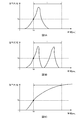
- FIG. 5A is a diagram showing an input pattern of operation force corresponding to high-precision translational movement.
- FIG. 5B is a diagram showing an input pattern of an operating force corresponding to high precision rotational movement.
- 5C is a diagram showing an input pattern of an operating force corresponding to high speed movement. It is a figure showing the movement form of the link member corresponding to the worker's operation pattern.
- FIG. 1 is an external view showing a configuration example of an articulated robot 10 to which a robot direct teaching device according to a first embodiment of the present invention is applied.
- the articulated robot 10 includes a base 11 and an arm 12 supported by the base 11.
- the arm 12 has six degrees of freedom, and includes six link members 21a to 21f, six joint parts 22a to 22f, and a hand part 23. That is, the articulated robot 10 is a general six-axis articulated robot.
- the robot direct teaching device and method according to the present invention do not lose their essence depending on the configuration and the degree of freedom of the articulated robot.
- the link members 21a to 21f respectively have axes J1 to J6, and are disposed in order from the base end side of the arm 12 toward the tip end side.
- the end portion 23 is provided at the end of the link member 21 f and constitutes the end of the arm 12.
- the joint portions 22a to 22f are between the base 11 and the link member 21a, between the link members 21a and 21b, between the link members 21b and 21c, between the link members 21c and 21d, between the link members 21d and 21e, and 21e and 21f are connected to each other. Further, the joint portions 22a to 22f rotatably support the link members 21a to 21f around the axes J1 to J6.
- the operator When performing the teaching operation for the articulated robot 10, the operator operates any one of the link members 21a to 22f. That is, the operating force applied by the operator acts on a plurality of axes among the six axes J1 to J6, and the axes J1 to J6 on which the operating force is applied move as the operating axis, and the entire arm 12 Move it. At this time, the position and posture of the hand portion 23 are taught because the hand portion 23 translates or rotationally moves with linear or rotational movement of the operation axis.
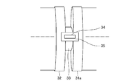
- FIG. 2 is a view showing the installation state of the torque sensor 34 in each of the joint portions 22a to 22f.
- the rotary shaft 31a of the motor 31, the central shaft 32 of the link members 21a to 21f, the connecting shaft 33, and the torque sensor 34 serving as a force sensor are provided in each of the joint portions 22a to 22f. It is done.
- the motor 31 rotates the link members 21a to 21f around the central axis 32 thereof.
- the torque sensor 34 detects an operation force acting on the central axis 32 of each of the link members 21a to 21f.
- the rotating shaft 31 a of the motor 31 and the central shaft 32 are connected via the connecting shaft 33.
- the shaft diameter of the connecting shaft 33 is smaller than the shaft diameter of the rotary shaft 31 a and the shaft diameter of the central shaft 32.
- the joint shafts of the rotary shaft 31a, the central shaft 32, and the connecting shaft 33 of the motor 31 and the joint portions 22a to 22f are coaxial with the respective axes J1 to J6. That is, the rotation axis 31a, the center axis 32, and the connection axis 33 rotate around the axes J1 to J6.
- the torque sensor 34 is attached to the rotating shaft 31 a and the central shaft 32 via the mounting plate 35, and rotates with the shafts 31 a and 32.
- the mounting plate 35 is provided between the outer peripheral surface of the rotary shaft 31 a and the outer peripheral surface of the central shaft 32 so as to bridge an axial gap formed therebetween.
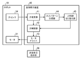
- FIG. 3 is a block diagram showing the configuration of a direct teaching device 40 for a robot according to Embodiment 1 of the present invention.
- the direct teaching device 40 shown in FIG. 3 enables the worker to directly teach the articulated robot 10, and is connected to the articulated robot 10 and the direct teaching instruction unit 36.
- the direct teaching instruction unit 36 is used when the operator instructs the teaching device 40 to directly teach the articulated robot 10. The operator can select execution or stop of direct teaching to the articulated robot 10 by switching operation of the direct teaching instruction unit 36.
- the direct teaching device 40 includes a force estimation unit 41, a force control unit 42, a motor driver 43, an input pattern classification unit 44, and a force control switching unit 45.
- the force estimation unit 41 estimates, based on the output result of the torque sensor 34, the link members 21a to 21f to which the operating force is applied by the operator, and the magnitude (input pattern) of the operating force.
- the force control unit 42 controls the drive of the motor driver 43 based on the estimation result of the force estimation unit 41.
- the motor driver 43 controls the rotation angle of the motor 31.
- the force control unit 42 controls the drive of the motor driver 43 based on the link members 21a to 21f to which the operating force is directly applied and the magnitude of the operating force, and the rotation angle of each motor 31 Adjust the
- the direct teaching device 40 operates the arm 12 based on the operation force, guides the hand portion 23 thereof to a working position as a target position, and teaches the working position.
- the hand portion 23 contacts the work object from any direction, in any posture, and with any force.
- This preset input pattern is an input pattern of the operating force, and a time when the applied operating force exceeds a predetermined threshold is set as an input start time, and the magnitude of the operating force is from the input start time It is classified into a plurality of types according to how it changes within a predetermined period.
- an input pattern in which the applied operating force is equal to or less than the threshold within a predetermined period from the input start time is taken as the input pattern of the operating force corresponding to the high precision movement of the arm 12. Further, an input pattern in which the applied operating force always exceeds the threshold within a predetermined period from the input start time is taken as the input pattern of the operating force corresponding to the high speed movement of the arm 12.
- the operator selects a plurality of types of input patterns set in advance, an operation pattern (an operation on the link members 21a to 21f) for the input pattern of the operation force to be applied to become an input pattern set in advance, and a link member after operation
- the movement modes of 21a to 21f and hand portion 23 are stored in advance.
- the input pattern classification unit 44 determines whether or not the input pattern of the operating force estimated by the force estimation unit 41 matches the preset input pattern, and when they match, The input pattern of the estimated operation force is classified into one of an input pattern corresponding to high precision movement and an input pattern corresponding to high speed movement.
- the force control switching unit 45 switches the force control of the force control unit 42 according to the type of the input pattern of the operating force classified by the input pattern classification unit 44.
- the force control switching unit 45 executes an operation defined in advance by the link members 21a to 21f serving as the operation axis. Command the force control unit 42 to do so.
- the force control switching unit 45 performs force control so that the conventional direct teaching can be performed by the light operating force. It instructs the part 42.
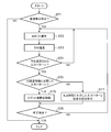
- step ST1 the operator determines whether to instruct the teaching device 40 to directly teach the articulated robot 10 directly.
- the process proceeds to step ST2.
- the processing is ended.
- step ST2 the operator applies an operating force to any one of the link members 21a to 21f among the link members 21a to 21f to guide the hand 23 toward the target position.
- each torque sensor 34 detects the force acting on the axes J1 to J6 of the link members 21a to 21f.
- step ST3 the force estimation unit 41 estimates, based on the detection results of all the torque sensors 34, the link members 21a to 21f to which the operating force has been applied and the magnitude of the operating force.
- the force estimation unit 41 uses the fact that no force acts on the link member located on the tip end side of the link member to which the operation force is applied (the output value of the torque sensor 34 does not change).
- the link members 21a to 21f to which the operation force is applied are estimated.
- the force estimation unit 41 estimates the magnitude of the operation force using the following equation (1).
- f J- T ⁇ ...
- f [fx fy fz f ⁇ f ⁇ f ⁇ ]
- J Gravity compensated output value
- J [axial direction of link member to which operating force is applied Velocity in the center]
- J ⁇ Matrix satisfying [speed of joint corresponding to link member to which operation force is applied]
- fx, fy, fz are translational forces in three orthogonal axes
- f ⁇ , f ⁇ , f ⁇ are in three orthogonal axes It is each torque.
- ⁇ 1, ⁇ 2, ⁇ 3, ⁇ 4, ⁇ 5 and ⁇ 6 are gravity-compensated output values of the six torque sensors 34.
- step ST4 the input pattern classification unit 44 determines whether the estimated input pattern of the operating force matches any one of a plurality of types of input patterns set in advance. Here, if it is determined that the estimated input pattern of the operating force matches the input pattern set in advance, the process proceeds to step ST5. On the other hand, when it is determined that the estimated input pattern of the operating force does not match the preset input pattern, the process returns to step ST2.
- step ST5 the input pattern classification unit 44 determines whether or not the input pattern of the estimated operation force can be classified into the input pattern corresponding to the high precision movement.
- the process proceeds to step ST6.
- the process proceeds to step ST7.
- FIG. 6 shows the link member 21a as a representative of the link members 21a to 21f. Moreover, the white arrow of FIG. 6 has shown the direction which an operator strikes.
- the input pattern of the operating force shown in FIG. 5A is an input pattern corresponding to the high precision movement of the arm 12.
- the input pattern corresponding to this high-precision movement assumes that the time when the applied operating force exceeds the predetermined threshold value fo is the input start time to, and the operating force is 1 within the predetermined period t from the input start time to.
- the input pattern is equal to or less than the threshold value fo, and ends as it is. That is, in the input pattern corresponding to the high precision movement, the operating force has one peak value within the predetermined period t from the input start time to.
- the operation pattern of the worker for obtaining such an input pattern is an operation of tapping any one of the link members 21a to 21f once.
- the input pattern of the operating force shown in FIG. 5B is another input pattern corresponding to the high precision movement of the arm 12.
- the input pattern corresponding to the high precision movement is an input pattern in which the applied operation force is twice or less the threshold fo within the predetermined period t from the input start time to, and is ended as it is. That is, in the input pattern corresponding to the high accuracy movement, the operating force has two peak values within a predetermined period t from the input start time to.
- the operation pattern of the worker for obtaining such an input pattern is an operation of tapping any one of the link members 21a to 21f twice.
- the input pattern of the operating force shown in FIG. 5C is an input pattern corresponding to the high speed movement of the arm 12.
- the input pattern corresponding to the high-speed movement is an input pattern in which the applied operating force always exceeds the threshold value fo within a predetermined period t from the input start time to.
- the operation pattern of the worker for obtaining such an input pattern is an operation of continuously pressing the link members 21a to 21f.
- step ST6 the hand portion 23 is taught by the conventional direct teaching to teach a target position and a target posture.
- the force control unit 42 determines the action direction (translational direction) of the applied operating force.
- the force control unit 42 rotates the hand unit 23 according to the acting direction of the operating force.
- the force control unit 42 rotates the link members 21a, 21c, and 21e.
- the link members 21b, 21d and 21f are set to be rotated in the rotational direction R2 while being rotated in the direction R1.
- the hand 23 follows the rotation of the link members 21a, 21c, 21e in the rotational direction R1. , And rotates about the axes J1, J3, and J5.
- the hand 23 follows the rotation of the link members 21b, 21b, 21f in the rotational direction R2. , And rotates about the axes J2, J4, and J6.
- the force control unit 42 controls the axes of the link members 21a to 21f.
- Linking member when the crossing angle ⁇ f between the reference line O and the action direction of the operating force passing through the axes J1 to J6 is 0 to 179 [deg], with the reference line O passing J1 to J6 as the reference angle
- the link members 21a to 21f are rotated in the rotational direction R2 while rotating 21a to 21f in the rotational direction R1, while being 180 to 359 [deg].
- the hit link members 21a to 21f rotate in the rotational direction R1 or rotational direction R2 according to the crossing angle ⁇ f. Rotate towards. As a result, the end portion 23 rotates around the axes J1 to J6 of the hit link members 21a to 21f.
- the force control unit 42 sets the target rotation angle ⁇ r6 of the link member 21f using the following equation (4) even when one of the two force control methods described above is adopted.
- ⁇ ri ⁇ i + Ks (4)
- ⁇ i A current rotation angle at the link member corresponding to i: Constant s: a variable that is “1” in the rotation direction R1 and “ ⁇ 1” in the rotation direction R2
- step ST7 the hand portion 23 teaches a target position and a target posture by moving according to the conventional direct teaching such that the arm 12 can be moved by a light operation force.
- the process proceeds to step ST8.
- step ST8 the operator determines whether to direct the teaching device 40 to finish direct teaching to the articulated robot 10.
- the processing is ended.
- the process proceeds to step ST2.
- the robot direct teaching apparatus and the direct teaching method according to the first embodiment can selectively use high-speed movement and high-precision movement at the time of teaching work to the articulated robot 10 without reducing the teaching efficiency. .
- one 6-axis force sensor (not shown) is substituted for the six torque sensors 34 in the robot direct teaching apparatus and method according to the first embodiment. ) Is provided in the end portion 23.
- the force estimation unit 41 estimates the magnitude of the operation force f using the following equation (5), using only the detection result of the six-axis force sensor which is a multi-axis force sensor.
- f [fx fy fz f ⁇ f ⁇ f ⁇ ] T (5)
- the force control unit 42 rotates the hand unit 23 according to the acting direction of the operating force. That is, when the six torque sensors 34 are provided, since they are provided corresponding to the respective axes J1 to J6, the force estimation unit 41 directly acts on which link members 21a to 21f. It can be estimated. On the other hand, when the six-axis force sensor is provided, since it is not provided corresponding to each axis J1 to J6, the force estimation unit 41 directly transmits the operating force to which link member 21a to 21f. It is not possible to estimate what worked. Therefore, the force control unit 42 adopts only the second force control method described above.
- the robot direct teaching apparatus and the direct teaching method according to the second embodiment can selectively use high-speed movement and high-precision movement at the time of teaching work to the articulated robot 10 without reducing the teaching efficiency. .
- the direct teaching device and method of the robot according to the present invention can use the high-speed movement and the high-precision movement properly without lowering the teaching efficiency at the time of teaching work to the robot.
- it is suitable for use in a direct teaching apparatus and method of a robot that directly teaches its hand position.
Landscapes
- Engineering & Computer Science (AREA)
- Robotics (AREA)
- Mechanical Engineering (AREA)
- Physics & Mathematics (AREA)
- General Physics & Mathematics (AREA)
- Automation & Control Theory (AREA)
- Manipulator (AREA)
- Numerical Control (AREA)
Abstract
複数の軸(J1~J6)を有する多関節ロボット(10)に加わる操作力を力センサ(34)によって検出し、その検出結果に基づいた力制御部(42)の力制御に従って、多関節ロボット(10)を移動させて、その位置を直接教示するロボットの直接教示装置(40)において、力センサ(34)の検出結果に基づいて、軸(J1~J6)に加えられた操作力を推定する力推定部(41)と、力推定部(41)によって推定された操作力の入力パターンを、予め設定された入力パターンの種類ごとに分類する入力パターン分類部(44)と、入力パターン分類部(44)によって分類された操作力の入力パターンに応じて、力制御部(42)の力制御を切り替える力制御切り替え部(45)とを備える。
Description
この発明は、ロボットに対して操作力を加えて、その手先位置を直接教示するロボットの直接教示装置及びその方法に関する。
従来、力制御に基づいたロボットの直接教示方法が、種々提供されている。このロボットの直接教示方法の1つとして、ロボットに加えた操作力を検出し、その検出結果に基づいてロボットを移動させて、その手先位置を直接教示する方法がある。このような、従来のロボットの直接教示方法としては、例えば、特許文献1に開示されている。
上記従来の直接教示方法においては、手先位置を教示する際に、軽い操作力によってロボットを高速移動させるモードと、強い操作力によってロボットを低速移動させるモードとの間で、切り替え可能としている。しかしながら、このような直接教示方法を採用すると、作業者は、教示モードを切り替える度に、スイッチ切り替え操作を必要とするため、ロボットに対する教示効率が低下するおそれがある。
この発明は、上記課題を解決するものであって、ロボットに対する教示作業時において、その教示効率を低下させることなく、高速移動と高精度移動とを使い分けることができるロボットの直接教示装置及びその方法を提供することを目的とする。
この発明に係るロボットの直接教示装置は、複数の軸を有する多関節ロボットに加わる操作力を力センサによって検出し、その検出結果に基づいた力制御部の力制御に従って、多関節ロボットを移動させて、その位置を直接教示するロボットの直接教示装置において、力センサの検出結果に基づいて、軸に加えられた操作力を推定する力推定部と、力推定部によって推定された操作力の入力パターンを、予め設定された入力パターンの種類ごとに分類する入力パターン分類部と、入力パターン分類部によって分類された操作力の入力パターンに応じて、力制御部の力制御を切り替える力制御切り替え部とを備えるものである。
この発明に係るロボットの教示方法は、複数の軸を有する多関節ロボットに加わる操作力を力センサによって検出し、その検出結果に基づいた力制御に従って、多関節ロボットを移動させて、その位置を直接教示するロボットの直接教示方法において、力センサの検出結果に基づいて、軸に加えられた操作力を推定し、推定された操作力の入力パターンを、予め設定された入力パターンの種類ごとに分類し、分類された操作力の入力パターンに応じて、力制御を切り替えるものである。
この発明によれば、ロボットに対する教示作業時において、その教示効率を低下させることなく、高速移動と高精度移動とを使い分けることができる。
以下、この発明の実施の形態について図面を参照しながら詳細に説明する。
実施の形態1.
図1は、この発明の実施の形態1に係るロボットの直接教示装置が適用される多関節ロボット10の構成例を示した外観図である。図1に示すように、多関節ロボット10は、基台11と、この基台11に支持されるアーム12とから構成されている。アーム12は、6自由度を有しており、6つのリンク部材21a~21f、6つの関節部22a~22f、及び、手先部23から構成されている。つまり、多関節ロボット10は、一般的な6軸多関節ロボットである。但し、本発明に係るロボット直接教示装置及びその方法は、多関節ロボットの構成及び自由度数によって、その本質が失われるものではない。
図1は、この発明の実施の形態1に係るロボットの直接教示装置が適用される多関節ロボット10の構成例を示した外観図である。図1に示すように、多関節ロボット10は、基台11と、この基台11に支持されるアーム12とから構成されている。アーム12は、6自由度を有しており、6つのリンク部材21a~21f、6つの関節部22a~22f、及び、手先部23から構成されている。つまり、多関節ロボット10は、一般的な6軸多関節ロボットである。但し、本発明に係るロボット直接教示装置及びその方法は、多関節ロボットの構成及び自由度数によって、その本質が失われるものではない。
リンク部材21a~21fは、軸J1~J6をそれぞれ有しており、アーム12の基端側から先端側に向けて順に配置されている。手先部23は、リンク部材21fの先端に設けられており、アーム12の先端部を構成している。
関節部22a~22fは、基台11とリンク部材21aとの間、リンク部材21a,21b間、リンク部材21b,21c間、リンク部材21c,21d間、リンク部材21d,21e間、及び、リンク部材21e,21f間を、それぞれ繋いでいる。更に、関節部22a~22fは、リンク部材21a~21fを軸J1~J6周りに回転可能に支持している。
上記多関節ロボット10に対する教示作業を行う場合には、作業者は、リンク部材21a~22fのうち、いずれか1つのリンク部材21a~22fを操作する。つまり、作業者から加えられた操作力は、6つの軸J1~J6のうち、複数の軸に作用し、その操作力が作用した軸J1~J6は、操作軸として移動し、アーム12全体を移動させる。このとき、手先部23は、操作軸の直線移動または回転移動に伴って、並進移動または回転移動するため、その位置及び姿勢が教示される。
図2は、各関節部22a~22fにおけるトルクセンサ34の設置状態を示した図である。図2に示すように、モータ31の回転軸31a、リンク部材21a~21fの中心軸32、連結軸33、及び、力センサとなるトルクセンサ34は、各関節部22a~22f内に、それぞれ設けられている。モータ31は、リンク部材21a~21fを、その中心軸32を回転中心として回転させる。トルクセンサ34は、各リンク部材21a~21fの中心軸32に作用した操作力をそれぞれ検出する。
モータ31の回転軸31aと中心軸32とは、連結軸33を介して連結されている。連結軸33の軸径は、回転軸31aの軸径及び中心軸32の軸径よりも小径となっている。モータ31の回転軸31a、中心軸32、連結軸33は、及び、関節部22a~22fの関節軸は、各軸J1~J6と同軸状になっている。つまり、回転軸31a、中心軸32、及び、連結軸33は、軸J1~J6周りに回転する。
トルクセンサ34は、取付板35を介して、回転軸31a及び中心軸32に取り付けられており、それらの軸31a,32と共に回転する。取付板35は、回転軸31aの外周面と中心軸32の外周面との間において、それらの間に形成される軸方向隙間を跨ぐように設けられている。これにより、トルクセンサ34は、作業者による操作力が中心軸32に作用すると、これに伴って歪を生じ、その歪量を、操作力の大きさに換算して検出する。
図3は、この発明の実施の形態1に係るロボットの直接教示装置40の構成を示したブロックである。図3に示した直接教示装置40は、多関節ロボット10に対する作業者の直接教示作業を可能にするものであって、多関節ロボット10及び直接教示指示部36と接続されている。
直接教示指示部36は、作業者が、多関節ロボット10に対して直接教示を行うことを、直接教示装置40に指示する際に使用するものである。作業者は、直接教示指示部36のスイッチ切り替え操作によって、多関節ロボット10に対する直接教示の実行または停止を選択することができる。
図3に示すように、直接教示装置40は、力推定部41、力制御部42、モータドライバ43、入力パターン分類部44、及び、力制御切り替え部45を有している。
力推定部41は、トルクセンサ34の出力結果に基づいて、作業者によって操作力が加えられたリンク部材21a~21f、及び、その操作力の大きさ(入力パターン)を推定する。力制御部42は、力推定部41の推定結果に基づいて、モータドライバ43の駆動を制御する。モータドライバ43は、モータ31の回転角度を制御する。
つまり、力制御部42は、操作力が直接的に加えられたリンク部材21a~21fと、その操作力の大きさとに基づいて、モータドライバ43の駆動を制御して、各モータ31の回転角度を調整する。これにより、直接教示装置40は、アーム12を操作力に基づいて動作させて、その手先部23を、目標位置となる作業位置に誘導し、その作業位置を教示する。この結果、手先部23は、作業対象物に対して、任意の方向から、任意の姿勢で、且つ、任意の力によって接触する。
入力パターン分類部44には、予め複数種類の入力パターンが設定されている。この予め設定された入力パターンは、操作力の入力パターンであって、加えられた操作力が所定の閾値を超えた時刻を、入力開始時刻とし、その操作力の大きさが、入力開始時刻から所定期間以内において、どのように変化するのかによって、複数種類に分類されている。
例えば、加えられた操作力が入力開始時刻から所定期間以内で閾値以下となる入力パターンは、アーム12の高精度移動に対応した操作力の入力パターンとする。また、加えられた操作力が入力開始時刻から所定期間以内で閾値を常に越えている入力パターンは、アーム12の高速移動に対応した操作力の入力パターンとする。
作業者は、予め設定された複数種類の入力パターン、加える操作力の入力パターンが予め設定された入力パターンとなるための動作パターン(リンク部材21a~21fに対する操作)、及び、動作後におけるリンク部材21a~21f及び手先部23の移動形態を、予め記憶している。これに対して、入力パターン分類部44は、力推定部41によって推定された操作力の入力パターンが、予め設定された入力パターンと一致するか否かを判断し、それらが一致した場合に、推定された操作力の入力パターンを、高精度移動に対応した入力パターン及び高速移動に対応した入力パターンのいずれか一方に分類する。
力制御切り替え部45は、入力パターン分類部44によって分類された、操作力の入力パターンの種類に応じて、力制御部42の力制御を切り替える。
力制御切り替え部45は、推定された操作力の入力パターンが、高精度移動に対応した入力パターンに分類された場合には、操作軸となるリンク部材21a~21fが予め規定された動作を実行するように、力制御部42に指令する。また、力制御切り替え部45は、推定された操作力の入力パターンが、高速移動に対応した入力パターンに分類された場合には、軽い操作力によって、従来の直接教示が行えるように、力制御部42に指令する。
次に、この発明の実施の形態1に係るロボットの直接教示装置の処理過程について、図4を用いて説明する。
先ず、ステップST1において、作業者は、多関節ロボット10に対する直接教示を行うことを、直接教示装置40に指示するか否かを判断する。ここで、直接教示を実行すると判断した場合には、ステップST2に進む。一方、直接教示を実行しないと判断した場合には、処理を終了する。
次いで、ステップST2において、作業者は、リンク部材21a~21fのうち、いずれか1つのリンク部材21a~21fに操作力を加えて、手先部23を、目標位置となる作業位置に向けて誘導する。このとき、各トルクセンサ34は、リンク部材21a~21fの軸J1~J6に作用する力を、それぞれ検出する。
そして、ステップST3において、力推定部41は、全てのトルクセンサ34の検出結果に基づいて、操作力が加えられたリンク部材21a~21f、及び、その操作力の大きさを推定する。
具体的に、力推定部41は、操作力が加えられたリンク部材よりも先端側に位置するリンク部材には力が作用しない(トルクセンサ34の出力値が変化しない)ことを利用して、操作力が加えられたリンク部材21a~21fを推定する。
また、力推定部41は、操作力の大きさを、下記の式(1)を用いて推定する。
f=J-Tτ …(1)
但し、
f=[fx fy fz fα fβ fγ]T:作業者が加えた操作力
τ=[τ1 τ2 τ3 τ4 τ5 τ6]T:重力補償済み出力値
J:[操作力が加えられたリンク部材の軸方向中央部における速度]=J×
[操作力が加えられたリンク部材に対応する関節部の速度]を満たす行列
なお、fx、fy、fzは、直交3軸における各並進力であり、fα、fβ、fγは、直交3軸における各回転力である。
また、τ1、τ2、τ3、τ4、τ5、τ6は、6つのトルクセンサ34の各重力補償済み出力値である。
f=J-Tτ …(1)
但し、
f=[fx fy fz fα fβ fγ]T:作業者が加えた操作力
τ=[τ1 τ2 τ3 τ4 τ5 τ6]T:重力補償済み出力値
J:[操作力が加えられたリンク部材の軸方向中央部における速度]=J×
[操作力が加えられたリンク部材に対応する関節部の速度]を満たす行列
なお、fx、fy、fzは、直交3軸における各並進力であり、fα、fβ、fγは、直交3軸における各回転力である。
また、τ1、τ2、τ3、τ4、τ5、τ6は、6つのトルクセンサ34の各重力補償済み出力値である。
次いで、ステップST4において、入力パターン分類部44は、推定された操作力の入力パターンが、予め設定された複数種類の入力パターンのいずれか1つと一致するか否かを判断する。ここで、推定された操作力の入力パターンが予め設定された入力パターンと一致したと判断した場合には、ステップST5に進む。一方、推定された操作力の入力パターンが予め設定された入力パターンと一致しないと判断した場合には、ステップST2に戻る。
そして、ステップST5において、入力パターン分類部44は、推定された操作力の入力パターンを、高精度移動に対応した入力パターンに分類することができるか否かを判断する。ここで、分類できると判断した場合には、ステップST6に進む。一方、分類できないと判断した場合には、ステップST7に進む。
ここで、入力パターン分類部44に予め設定された入力パターン、及び、それに対応したリンク部材21a~21fの動作形態について、図5Aから図5C及び図6を用いて説明する。なお、図6は、リンク部材21a~21fのうち、リンク部材21aを代表して図示している。また、図6の白抜き矢印は、作業者が叩く方向を示している。
図5Aに示した操作力の入力パターンは、アーム12の高精度移動に対応した入力パターンである。この高精度移動に対応した入力パターンは、加えられた操作力が所定の閾値foを超えた時刻を、入力開始時刻toとし、その操作力が、入力開始時刻toから所定期間t以内で、1回閾値fo以下となり、そのまま終了する入力パターンとなっている。つまり、上記高精度移動に対応した入力パターンは、操作力が、入力開始時刻toから所定期間t以内で、1つのピーク値を有している。これに対して、そのような入力パターンを得るための作業者の動作パターンは、リンク部材21a~21fのいずれか1つを1回叩く動作となっている。
これにより、図6に示すように、作業者によって、リンク部材21a~21fが1回叩かれると、アーム12の手先部23は、予め規定された動作量だけ、その叩かれた方向に向けて移動する。
図5Bに示した操作力の入力パターンは、アーム12の高精度移動に対応した他の入力パターンである。この高精度移動に対応した入力パターンは、加えられた操作力が、入力開始時刻toから所定期間t以内で、2回閾値fo以下となり、そのまま終了する入力パターンとなっている。つまり、上記高精度移動に対応した入力パターンは、操作力が、入力開始時刻toから所定期間t以内で、2つのピーク値を有している。これに対して、そのような入力パターンを得るための作業者の動作パターンは、リンク部材21a~21fのいずれか1つを2回叩く動作となっている。
これにより、図6に示すように、作業者によって、リンク部材21a~21fが2回叩かれると、アーム12の手先部23は、予め規定された動作量だけ、演算結果の方向に向けて回転する。
図5Cに示した操作力の入力パターンは、アーム12の高速移動に対応した入力パターンである。この高速移動に対応した入力パターンは、加えられた操作力が、入力開始時刻toから所定期間t以内において、常に閾値foを超える入力パターンとなっている。これに対して、そのような入力パターンを得るための作業者の動作パターンは、リンク部材21a~21fを押し続ける動作となっている。
次いで、ステップST6において、手先部23は、従来の直接教示によって移動することにより、目標位置及び目標姿勢が教示される。
具体的に、推定された操作力の入力パターンが高精度並進移動に対応した入力パターンに分類された合には、先ず、力制御部42は、加えられた操作力の作用方向(並進方向)gを、下記の式(2)を用いて推定する。
g=[fx fy fz]T/|[fx fy fz]T| …(2)
g=[fx fy fz]T/|[fx fy fz]T| …(2)
続いて、力制御部42は、操作力の作用方向gにおいて、手先部23の目標位置及び目標姿勢rを、下記の式(3)を用いて設定する。そして、手先部23は、現在の位置及び姿勢pから、設定した目標位置及び目標姿勢rに向けて、作用方向gに応じた移動方向に沿って移動する。
r=p+K[gT01×3]T …(3)
但し、
p=[px py pz pα pβ pγ]T:現在の位置及び姿勢
K:定数
r=p+K[gT01×3]T …(3)
但し、
p=[px py pz pα pβ pγ]T:現在の位置及び姿勢
K:定数
また、推定された操作力の入力パターンが高精度回転移動に対応した入力パターンに分類された場合には、力制御部42は、操作力の作用方向に応じて、手先部23を回転させる。
先ず、1つ目の力制御方法として、作業者が叩いたリンク部材21a~21fに応じて、手先部23を回転させる場合には、力制御部42は、リンク部材21a,21c,21eを回転方向R1に向けて回転させる一方、リンク部材21b,21d,21fを回転方向R2に向けて回転させるように設定する。
つまり、作業者がリンク部材21a,21c,21eのいずれか1つのリンク部材を2回叩いた場合には、手先部23は、リンク部材21a,21c,21eの回転方向R1への回転に伴って、その軸J1,J3,J5を回転中心として回転する。一方、作業者がリンク部材21b,21d,21fのいずれか1つのリンク部材を2回叩いた場合には、手先部23は、リンク部材21b,21b,21fの回転方向R2への回転に伴って、その軸J2,J4,J6を回転中心として回転する。
また、2つ目の力制御方法として、操作力の作用方向に応じて、手先部23を回転させる場合には、図6に示すように、力制御部42は、リンク部材21a~21fの軸J1~J6を通る基準線Oを基準角度として、その基準線Oと、軸J1~J6を通る操作力の作用方向との交差角度θfが、0~179[deg]であるときに、リンク部材21a~21fを回転方向R1に向けて回転させる一方、180~359[deg]であるときに、リンク部材21a~21fを回転方向R2に向けて回転させる。
つまり、作業者がリンク部材21a~21fのいずれか1つのリンク部材を2回叩いた場合には、叩かれたリンク部材21a~21fは、交差角度θfに応じて、回転方向R1または回転方向R2に向けて回転する。これにより、手先部23は、その叩かれたリンク部材21a~21fの軸J1~J6を回転中心として回転する。
力制御部42は、上述した2つの力制御方法のいずれかを採用した場合であっても、リンク部材21fの目標回転角度θr6を、下記の式(4)を用いて設定する。
θri=θi+Ks …(4)
但し、
i:リンク部材21a~21fに対応する番号(手先部23が回転する場合はi=6)
θi:iに対応するリンク部材における現在の回転角度
K:定数
s:回転方向R1のときは「1」、回転方向R2のときは「-1」となる変数
θri=θi+Ks …(4)
但し、
i:リンク部材21a~21fに対応する番号(手先部23が回転する場合はi=6)
θi:iに対応するリンク部材における現在の回転角度
K:定数
s:回転方向R1のときは「1」、回転方向R2のときは「-1」となる変数
これに対して、ステップST7において、手先部23は、アーム12を軽い操作力によって移動させることができるような、従来の直接教示によって、移動することにより、目標位置及び目標姿勢が教示される。このとき、加えられた操作力が閾値fo以下になると、ステップST8に進む。
次いで、ステップST8において、作業者は、多関節ロボット10に対する直接教示を終了することを、直接教示装置40に指示するか否かを判断する。ここで、直接教示を終了すると判断した場合には、処理を終了する。一方、直接教示を終了しないと判断した場合には、ステップST2に進む。
以上、実施の形態1に係るロボットの直接教示装置及び直接教示方法は、多関節ロボット10に対する教示作業時において、その教示効率を低下させることなく、高速移動と高精度移動とを使い分けることができる。
実施の形態2.
この実施の形態2に係るロボットの直接教示装置及びその方法は、実施の形態1に係るロボットの直接教示装置及びその方法における6つのトルクセンサ34に替えて、1つの6軸力センサ(図示省略)を手先部23に設けている。
この実施の形態2に係るロボットの直接教示装置及びその方法は、実施の形態1に係るロボットの直接教示装置及びその方法における6つのトルクセンサ34に替えて、1つの6軸力センサ(図示省略)を手先部23に設けている。
これにより、力推定部41は、多軸力センサとなる6軸力センサの検出結果のみを用いて、操作力fの大きさを、下記の式(5)を用いて推定する。
f=[fx fy fz fα fβ fγ]T …(5)
f=[fx fy fz fα fβ fγ]T …(5)
また、推定された操作力の入力パターンが高精度回転移動に対応した入力パターンに分類された場合には、力制御部42は、操作力の作用方向に応じて、手先部23を回転させる。つまり、6つのトルクセンサ34を設けた場合には、それらが各軸J1~J6に対応して設けられているため、力推定部41は、操作力がどのリンク部材21a~21fに直接作用したのかを推定することができる。これに対して、6軸力センサを設けた場合には、それが各軸J1~J6に対応して設けられていないため、力推定部41は、操作力がどのリンク部材21a~21fに直接作用したのかを推定することができない。従って、力制御部42は、上述した2つ目の力制御方法のみを採用する。
以上、実施の形態2に係るロボットの直接教示装置及び直接教示方法は、多関節ロボット10に対する教示作業時において、その教示効率を低下させることなく、高速移動と高精度移動とを使い分けることができる。
なお、本願発明は、その発明の範囲内において、各実施の形態の自由な組み合わせ、あるいは、各実施の形態における任意の構成要素の変形、もしくは、各実施の形態における任意の構成要素の省略が可能である。
本発明に係るロボットの直接教示装置及びその方法は、ロボットに対する教示作業時において、その教示効率を低下させることなく、高速移動と高精度移動とを使い分けることができるので、ロボットに対して操作力を加えて、その手先位置を直接教示するロボットの直接教示装置及びその方法で用いるのに適している。
10 多関節ロボット
11 基台
12 アーム
21a~21f リンク部材
22a~22f 関節部
23 手先部
31 モータ
31a 回転軸
32 中心軸
33 連結軸
34 トルクセンサ
35 取付板
36 直接教示指示部
40 直接教示装置
41 力推定部
42 力制御部
43 モータドライバ
44 入力パターン分類部
45 力制御切り替え部
J1~J6 軸
11 基台
12 アーム
21a~21f リンク部材
22a~22f 関節部
23 手先部
31 モータ
31a 回転軸
32 中心軸
33 連結軸
34 トルクセンサ
35 取付板
36 直接教示指示部
40 直接教示装置
41 力推定部
42 力制御部
43 モータドライバ
44 入力パターン分類部
45 力制御切り替え部
J1~J6 軸
Claims (6)
- 複数の軸を有する多関節ロボットに加わる操作力を力センサによって検出し、その検出結果に基づいた力制御部の力制御に従って、前記多関節ロボットを移動させて、その位置を直接教示するロボットの直接教示装置において、
前記力センサの検出結果に基づいて、前記軸に加えられた操作力を推定する力推定部と、
前記力推定部によって推定された操作力の入力パターンを、予め設定された入力パターンの種類ごとに分類する入力パターン分類部と、
前記入力パターン分類部によって分類された操作力の入力パターンに応じて、前記力制御部の力制御を切り替える力制御切り替え部とを備える
ことを特徴とするロボットの直接教示装置。 - 前記力制御部は、
推定された操作力の入力パターンが、前記多関節ロボットの回転移動に対応した入力パターンに分類された場合には、
前記多関節ロボットにおける手先部の回転方向を制御する
ことを特徴とする請求項1記載のロボットの直接教示装置。 - 前記力制御部は、
推定された操作力の入力パターンが、前記多関節ロボットの並進移動に対応した入力パターンに分類された場合には、
前記多関節ロボットにおける手先部の移動方向を、操作力の作用方向に応じて制御する
ことを特徴とする請求項1記載のロボットの直接教示装置。 - 前記力センサは、前記多関節ロボットの各関節部に設けられ、
前記力推定部は、前記複数の軸の中から、操作力が加えられた軸を推定する
ことを特徴とする請求項1から請求項3のうちのいずれか1項記載のロボットの直接教示装置。 - 前記力センサは、前記多関節ロボットの手先部に設けられた多軸力センサである
ことを特徴とする請求項1から請求項3のうちのいずれか1項記載のロボットの直接教示装置。 - 複数の軸を有する多関節ロボットに加わる操作力を力センサによって検出し、その検出結果に基づいた力制御に従って、前記多関節ロボットを移動させて、その位置を直接教示するロボットの直接教示方法において、
前記力センサの検出結果に基づいて、前記軸に加えられた操作力を推定し、
推定された操作力の入力パターンを、予め設定された入力パターンの種類ごとに分類し、
分類された操作力の入力パターンに応じて、力制御を切り替える
ことを特徴とするロボットの直接教示方法。
Priority Applications (2)
| Application Number | Priority Date | Filing Date | Title |
|---|---|---|---|
| KR1020207012612A KR20200064115A (ko) | 2017-11-27 | 2018-10-15 | 로봇의 직접 교시 장치 및 그 방법 |
| CN201880072646.7A CN111356559A (zh) | 2017-11-27 | 2018-10-15 | 机械手的直接教示装置及其方法 |
Applications Claiming Priority (2)
| Application Number | Priority Date | Filing Date | Title |
|---|---|---|---|
| JP2017227223A JP6964494B2 (ja) | 2017-11-27 | 2017-11-27 | ロボットの直接教示装置及びその方法 |
| JP2017-227223 | 2017-11-27 |
Publications (1)
| Publication Number | Publication Date |
|---|---|
| WO2019102746A1 true WO2019102746A1 (ja) | 2019-05-31 |
Family
ID=66631455
Family Applications (1)
| Application Number | Title | Priority Date | Filing Date |
|---|---|---|---|
| PCT/JP2018/038332 Ceased WO2019102746A1 (ja) | 2017-11-27 | 2018-10-15 | ロボットの直接教示装置及びその方法 |
Country Status (4)
| Country | Link |
|---|---|
| JP (1) | JP6964494B2 (ja) |
| KR (1) | KR20200064115A (ja) |
| CN (1) | CN111356559A (ja) |
| WO (1) | WO2019102746A1 (ja) |
Cited By (3)
| Publication number | Priority date | Publication date | Assignee | Title |
|---|---|---|---|---|
| WO2021078344A1 (en) * | 2019-10-22 | 2021-04-29 | Universal Robots A/S | Safe activation of free-drive mode of robot arm |
| US12296485B2 (en) | 2019-10-22 | 2025-05-13 | Universal Robots A/S | Robot arm with adaptive three-dimensional boundary in free-drive |
| US12397414B2 (en) | 2019-10-22 | 2025-08-26 | Universal Robots A/S | Maintaining free-drive mode of robot arm for period of time |
Families Citing this family (3)
| Publication number | Priority date | Publication date | Assignee | Title |
|---|---|---|---|---|
| JP7095944B2 (ja) * | 2018-09-07 | 2022-07-05 | アズビル株式会社 | ロボットの直接教示装置及び直接教示方法 |
| CN109623830B (zh) * | 2018-11-27 | 2021-11-30 | 佛山科学技术学院 | 一种基于多传感器的机器人任务示教方法及系统 |
| JP2021062436A (ja) * | 2019-10-11 | 2021-04-22 | セイコーエプソン株式会社 | 教示方法 |
Citations (6)
| Publication number | Priority date | Publication date | Assignee | Title |
|---|---|---|---|---|
| JPH03123907A (ja) * | 1989-10-06 | 1991-05-27 | Hitachi Constr Mach Co Ltd | ロボットの直接教示装置及び直接教示方法 |
| JP2008110406A (ja) * | 2006-10-27 | 2008-05-15 | Yaskawa Electric Corp | ロボットの直接教示装置 |
| JP2009297853A (ja) * | 2008-06-16 | 2009-12-24 | Denso Wave Inc | ロボットのダイレクトティーチ制御装置 |
| WO2010079564A1 (ja) * | 2009-01-09 | 2010-07-15 | パナソニック株式会社 | ロボットアームの制御装置及び制御方法、ロボット、ロボットアームの制御プログラム、並びに、集積電子回路 |
| JP2014128843A (ja) * | 2012-12-28 | 2014-07-10 | Toyota Motor Corp | ロボットアーム教示システム及びロボットアーム教示方法 |
| JP2017074669A (ja) * | 2015-10-14 | 2017-04-20 | 株式会社リコー | マニピュレータの制御装置、マニピュレータ駆動装置、及びロボットシステム |
Family Cites Families (3)
| Publication number | Priority date | Publication date | Assignee | Title |
|---|---|---|---|---|
| JPH08336785A (ja) * | 1995-06-09 | 1996-12-24 | Yaskawa Electric Corp | 産業用ロボットの教示装置 |
| JP5893665B2 (ja) * | 2014-04-14 | 2016-03-23 | ファナック株式会社 | 作用された力に応じて移動されるロボットを制御するロボット制御装置 |
| JP6489991B2 (ja) * | 2015-10-02 | 2019-03-27 | ファナック株式会社 | ロボットを操作するハンドルを備えたロボット用操作装置 |
-
2017
- 2017-11-27 JP JP2017227223A patent/JP6964494B2/ja not_active Expired - Fee Related
-
2018
- 2018-10-15 CN CN201880072646.7A patent/CN111356559A/zh active Pending
- 2018-10-15 WO PCT/JP2018/038332 patent/WO2019102746A1/ja not_active Ceased
- 2018-10-15 KR KR1020207012612A patent/KR20200064115A/ko not_active Ceased
Patent Citations (6)
| Publication number | Priority date | Publication date | Assignee | Title |
|---|---|---|---|---|
| JPH03123907A (ja) * | 1989-10-06 | 1991-05-27 | Hitachi Constr Mach Co Ltd | ロボットの直接教示装置及び直接教示方法 |
| JP2008110406A (ja) * | 2006-10-27 | 2008-05-15 | Yaskawa Electric Corp | ロボットの直接教示装置 |
| JP2009297853A (ja) * | 2008-06-16 | 2009-12-24 | Denso Wave Inc | ロボットのダイレクトティーチ制御装置 |
| WO2010079564A1 (ja) * | 2009-01-09 | 2010-07-15 | パナソニック株式会社 | ロボットアームの制御装置及び制御方法、ロボット、ロボットアームの制御プログラム、並びに、集積電子回路 |
| JP2014128843A (ja) * | 2012-12-28 | 2014-07-10 | Toyota Motor Corp | ロボットアーム教示システム及びロボットアーム教示方法 |
| JP2017074669A (ja) * | 2015-10-14 | 2017-04-20 | 株式会社リコー | マニピュレータの制御装置、マニピュレータ駆動装置、及びロボットシステム |
Cited By (5)
| Publication number | Priority date | Publication date | Assignee | Title |
|---|---|---|---|---|
| WO2021078344A1 (en) * | 2019-10-22 | 2021-04-29 | Universal Robots A/S | Safe activation of free-drive mode of robot arm |
| CN114585483A (zh) * | 2019-10-22 | 2022-06-03 | 优傲机器人公司 | 安全激活机器人臂的自由驱动模式 |
| US12296485B2 (en) | 2019-10-22 | 2025-05-13 | Universal Robots A/S | Robot arm with adaptive three-dimensional boundary in free-drive |
| US12384019B2 (en) | 2019-10-22 | 2025-08-12 | Universal Robots A/S | Safe activation of free-drive mode of robot arm |
| US12397414B2 (en) | 2019-10-22 | 2025-08-26 | Universal Robots A/S | Maintaining free-drive mode of robot arm for period of time |
Also Published As
| Publication number | Publication date |
|---|---|
| JP6964494B2 (ja) | 2021-11-10 |
| KR20200064115A (ko) | 2020-06-05 |
| JP2019093526A (ja) | 2019-06-20 |
| CN111356559A (zh) | 2020-06-30 |
Similar Documents
| Publication | Publication Date | Title |
|---|---|---|
| WO2019102746A1 (ja) | ロボットの直接教示装置及びその方法 | |
| CN108290257B (zh) | 机器人系统以及控制方法 | |
| CN107820456B (zh) | 用于冗余优化地规划移动式机器人的操作的方法 | |
| US20160129588A1 (en) | Event-Based Redundancy Angle Configuration for Articulated-Arm Robots | |
| US20060178775A1 (en) | Accelerometer to monitor movement of a tool assembly attached to a robot end effector | |
| CN108000477A (zh) | 一种全位姿主被动柔顺机器人及利用该机器人的旋拧阀门方法 | |
| JP2015033747A (ja) | ロボットシステム、ロボット制御装置及びロボット制御方法 | |
| JP2015155126A (ja) | ロボットシステムのツール座標系補正方法、およびロボットシステム | |
| JP2021121451A (ja) | 教示方法およびロボットシステム | |
| JP2018528085A (ja) | ロボットアームおよびロボットリスト | |
| CN107199562B (zh) | 机器人控制装置和机器人控制方法 | |
| JP7140508B2 (ja) | パラレルリンク機構を用いた作業装置およびその制御方法 | |
| JPH0438553B2 (ja) | ||
| JP2022539813A (ja) | 異なる方向範囲にわたるロボットマニピュレータのエンドエフェクタの触覚フィードバック | |
| JP7154748B2 (ja) | ロボットシステム、物品の製造方法、制御方法、制御プログラム、及び記録媒体 | |
| JP2016221653A (ja) | ロボット制御装置およびロボットシステム | |
| JP7595978B2 (ja) | ロボット及びロボット用手先部材 | |
| CN111716343B (zh) | 机器人 | |
| JPS6149075B2 (ja) | ||
| JP4378517B2 (ja) | 丸型ハンドルバルブ操作用ロボットアーム制御装置 | |
| CN119795137B (zh) | 一种高空作业车的末端执行机构及其控制方法 | |
| JP2021130146A (ja) | マニピュレータの制御装置 | |
| JP2713702B2 (ja) | ロボットの制御方法および装置 | |
| JP7414426B2 (ja) | ロボットシステム | |
| WO2026078878A1 (ja) | 教示装置、ロボットシステムおよび教示プログラムの作成方法 |
Legal Events
| Date | Code | Title | Description |
|---|---|---|---|
| 121 | Ep: the epo has been informed by wipo that ep was designated in this application |
Ref document number: 18881344 Country of ref document: EP Kind code of ref document: A1 |
|
| ENP | Entry into the national phase |
Ref document number: 20207012612 Country of ref document: KR Kind code of ref document: A |
|
| NENP | Non-entry into the national phase |
Ref country code: DE |
|
| 122 | Ep: pct application non-entry in european phase |
Ref document number: 18881344 Country of ref document: EP Kind code of ref document: A1 |