WO2019102575A1 - Engin de chantier et procédé de recherche de position de préhension - Google Patents
Engin de chantier et procédé de recherche de position de préhension Download PDFInfo
- Publication number
- WO2019102575A1 WO2019102575A1 PCT/JP2017/042154 JP2017042154W WO2019102575A1 WO 2019102575 A1 WO2019102575 A1 WO 2019102575A1 JP 2017042154 W JP2017042154 W JP 2017042154W WO 2019102575 A1 WO2019102575 A1 WO 2019102575A1
- Authority
- WO
- WIPO (PCT)
- Prior art keywords
- gripping
- interference
- candidate
- candidate position
- rotationally symmetric
- Prior art date
Links
Images


Classifications
-
- B—PERFORMING OPERATIONS; TRANSPORTING
- B25—HAND TOOLS; PORTABLE POWER-DRIVEN TOOLS; MANIPULATORS
- B25J—MANIPULATORS; CHAMBERS PROVIDED WITH MANIPULATION DEVICES
- B25J13/00—Controls for manipulators
- B25J13/08—Controls for manipulators by means of sensing devices, e.g. viewing or touching devices
Definitions
- This specification discloses a work machine and a gripping position search method.
- the work machine and the gripping position search method of the present disclosure have as a main object to efficiently grip the gripping target part even if the gripping target part is interfered by an obstacle such as another part.
- the working machine of the present disclosure is A chucking member for holding, as a gripping position, two mutually opposing points of the rotationally symmetric figure among gripping target parts of which at least one surface is a rotationally symmetric figure;
- a storage device for storing a plurality of parts including the gripping target part;
- An imaging device for imaging the plurality of components stored in the storage device from above;
- the predetermined initial gripping position is set as a candidate position, and the candidate position interferes with the gripping operation of the chuck member based on the candidate position and the image captured by the imaging device.
- the gripping position is rotated by a predetermined angle at which the rotational symmetry of the rotationally symmetric figure of the gripping target component appears.
- the next grasping position to be obtained is set as the candidate position, and the search process of determining again whether the candidate position is the non-interference holding position is repeated until the non-interference holding position is found, the non-interference
- a control device that controls the chuck member to grip the gripping target component at a gripping position; Is provided.
- a predetermined initial gripping position is set as a candidate position, and based on the candidate position and an image obtained by imaging a plurality of parts including a gripping target component stored in the storage device from above, It is determined whether the candidate position is a non-interference holding position without an obstacle that interferes with the holding operation of the chuck member. Then, if the candidate position is not a non-interference gripping position, the next gripping position obtained by rotating the gripping position by a predetermined angle at which the rotational symmetry of the rotationally symmetric figure of the gripping target part appears is set as the candidate position. The search process of determining again whether or not the candidate position is the non-interference holding position is repeated until the non-interference holding position is found.
- the positional relationship between the chuck member and the gripping target component when gripping the gripping target component at the initial gripping position is the position of the chuck member and the gripping target component when gripping the gripping target component at another gripping position. It will be the same as the relationship. This is because each gripping position is obtained by rotating the gripping position immediately before it by a predetermined angle at which the rotational symmetry of the rotationally symmetric figure of the gripping target part appears. According to this work machine, even if the gripping target component is interfered by the obstacle at the initial gripping position, it may not be interfered at the next gripping position, and the probability of being grippable is improved. Therefore, the gripping target component can be gripped efficiently.
- the grip position search method of the present disclosure is A gripping position search method used when controlling a chuck member that grips and holds two mutually opposing points of the rotationally symmetric figure among the gripping target parts having at least one surface that is a rotationally symmetric figure as gripping positions, (A) acquiring an image obtained by imaging a plurality of parts including the gripping target part stored in a storage device from above; (B) An obstacle in which the candidate position interferes with the gripping operation of the chuck member based on the candidate position and the image acquired in step (a), with the predetermined initial gripping position set as the candidate position It is determined whether or not the object is a non-interference holding position, and if the candidate position is not the non-interference holding position, the holding position is a predetermined angle at which the rotational symmetry of the rotationally symmetric figure of the object to be held appears. Is set as the candidate position, and it is determined again whether or not the candidate position is the non-interference holding position until the non-interference holding position is found. Step and I
- a predetermined initial gripping position is set as a candidate position, and the candidate position is based on an image obtained by imaging a plurality of parts including the gripping target component stored in the storage device from above Then, it is determined whether the candidate position is a non-interference holding position without an obstacle that interferes with the holding operation of the chuck member. Then, if the candidate position is not a non-interference gripping position, the next gripping position obtained by rotating the gripping position by a predetermined angle at which the rotational symmetry of the rotationally symmetric figure of the gripping target part appears is set as the candidate position. The search process of determining again whether or not the candidate position is the non-interference holding position is repeated until the non-interference holding position is found.
- the positional relationship between the chuck member and the gripping target component when gripping the gripping target component at the initial gripping position is the position of the chuck member and the gripping target component when gripping the gripping target component at another gripping position. It will be the same as the relationship. This is because each gripping position is obtained by rotating the gripping position immediately before it by a predetermined angle at which the rotational symmetry of the rotationally symmetric figure of the gripping target part appears. According to this gripping position search method, even if the gripping target component is interfered by the obstacle at the initial gripping position, it may not be interfered at the next gripping position. Therefore, the probability of finding the gripping position at which the gripping target component can be gripped is improved.
- FIG. 1 is a configuration diagram of a work transfer system 10.
- FIG. 2 is a perspective view of a mechanical chuck 22. Explanatory drawing which shows the electrical connection relation of the control apparatus 50.
- FIG. Explanatory drawing of the holding
- FIG. 5A is an explanatory view of the grip position of the washer 70
- FIG. 5A is an explanatory view of the case where the grip positions are two points on the outer periphery
- FIG. 5B is a case where the grip positions are one point on the outer periphery and one point on the inner periphery
- Explanatory drawing. 6 is a flowchart showing an example of a work transfer process. Explanatory drawing of the 1st-4th holding
- FIG. Explanatory drawing which shows the interference condition of the chuck
- Explanatory drawing which shows the interference condition of the chuck
- Explanatory drawing which shows the interference condition of the chuck
- Explanatory drawing which shows the interference condition of chuck
- FIG. 1 is a block diagram of the work transfer system 10
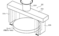
- FIG. 2 is a perspective view of the mechanical chuck 22
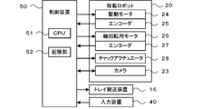
- FIG. 3 is an explanatory view showing an electrical connection of the control device 50.
- the lateral direction (X axis), the longitudinal direction (Y axis), and the vertical direction (Z axis) in the workpiece transfer system 10 will be described below as shown in FIG.
- the workpiece transfer system 10 collects the workpieces (components) in the supply box 14 and places them in the storage box 32 on the tray 30 or places them on the tray 30. It is a system to place.
- the work transfer system 10 includes a plurality of (for example, three) supply boxes 14, a tray transfer device 16, a transfer robot 20, and a control device 50 (see FIG. 3). Work is input to the supply box 14 from a supply robot, a supply conveyor, a worker, etc. (not shown). The positions, orientations, postures, etc. of the works in the supply box 14 are disjointed, and the works overlap with each other.
- the tray transfer device 16 drives the pair of front and rear conveyor belts to transfer the tray 30 in the left-right direction.
- the tray transfer device 16 and the transfer robot 20 are installed on the work table 11.
- the accommodation box 32 on the tray 30 is a box opened at the top, and a plurality (for example, three) of the accommodation boxes 32 are arranged on the tray 30.
- the storage box 32 has a size corresponding to, for example, the work to be stored, and can stack and store a plurality of works.
- the transfer robot 20 is a robot for collecting the work in the supply box 14 and placing the work on the tray 30 (including the storage box 32).
- the transfer robot 20 includes a vertical articulated robot arm 21 and a mechanical chuck 22 as an end effector.
- the robot arm 21 includes a plurality of links, a plurality of joints pivotably connecting the links, a plurality of drive motors 24 (see FIG. 3) driving the joints, and a plurality of encoders detecting angles of the joints 25 (see FIG. 3). In FIG. 3, one drive motor 24 and one encoder 25 are shown.
- FIG. 3 one drive motor 24 and one encoder 25 are shown.
- the mechanical chuck 22 has a pair of claws 22 a and 22 b attached to the lower surface of the base plate 22 c in an openable / closable manner.
- the pair of claws 22a and 22b are driven by the chuck actuator 28 (see FIG. 3) to open and close.
- the open position of the claws 22a and 22b is indicated by a solid line in FIG. 2, and the closed position is indicated by an alternate long and short dash line in FIG.
- a shaft 22d is attached to the center of the upper surface of the base plate 22c.
- the shaft 22d is axially rotated by a shaft rotation motor 26 (see FIG. 3) together with the base plate 22c and the pair of claws 22a and 22b.
- the rotation angle of the shaft 22d can be detected by the encoder 27 (see FIG. 3).
- a camera 23 is also attached to the tip link of the robot arm 21 for imaging a workpiece or the like in the supply box 14 located below and recognizing the position and the state of the workpiece.
- the control device 50 is configured as a microprocessor centering on the CPU 51, and includes a storage unit 52 such as a ROM or an HDD in addition to the CPU 51.
- Various signals from the encoders 25 and 27 of the transfer robot 20, the camera 23 and the input device 40 are input to the control device 50.
- the control device 50 outputs various control signals to the drive motor 24 of the transfer robot 20, the shaft rotation motor 26, the chuck actuator 28, the camera 23, the tray conveyance device 16, and the like.
- the operator can input, via the input device 40, a work instruction to the work transfer system 10, the type of work input to the supply box 14, and the like.
- the workpiece held by the mechanical chuck 22 has at least one surface of rotational symmetry.
- rotationally symmetric figures include circles and n-gons (n is an integer of 3 or more, preferably n is an even number of 4 or more).
- n is an integer of 3 or more, preferably n is an even number of 4 or more.
- the angle at which rotational symmetry appears is arbitrary, and in the case of a regular n-gon, the angle at which rotational symmetry appears is 360 ° / n or a multiple thereof.
- the work includes a circular plate, a washer (circular ring), a regular hexagonal plate, a nut (regular hexagonal ring) and the like.
- the circular plate and the regular hexagonal plate have a rotationally symmetric figure on the entire surface, and the washer and the nut have an annular shape, and both the inner circumferential shape and the outer circumferential shape are rotationally symmetric.
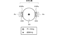
- the holding positions held by the pair of claws 22 a and 22 b are arbitrary two points 60 Pa and 60 Pb on the outer periphery facing each other across the center of the circular plate 60. .
- the gripping center at this time coincides with the center of the work (the center of the circular plate 60).
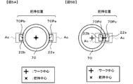
- the work is a washer 70 as shown in FIG. 5
- the first gripping position is arbitrary two points 70Pa and 70Pb on the outer periphery facing each other across the center of the washer 70 as shown in FIG.
- the gripping center at this time coincides with the center of the work (the center of the washer 70).
- the other gripping position is a total of two points 70Pc on the outer periphery of the washer 70 and a point 70Pd at which the line drawn from the point 70Pc to the center of the washer 70 intersects the inner periphery as shown in FIG. 5B. is there.
- the gripping center at this time (the middle of the line segment connecting the two points 70Pc and 70Pd) is offset from the center of the work (the center of the washer 70).
- dotted regions shown around the claws 22a and 22b represent the chuck movable range Ac.
- the chuck movable range Ac is set based on the size of the claws 22a and 22b, the tip shape, and the movable range of the claws 22a and 22b.
- FIG. 5 is a flowchart showing an example of the work transfer process.
- This routine is executed by the CPU 51 of the control device 50.
- the CPU 51 of the control device 50 first reads out information on the circular plate 60 which is a work to be transferred this time from the storage unit 52 (S100).
- the storage unit 52 In the storage unit 52, the outer diameter of the circular plate 60, the coordinates of the rotation center, the gripping position, a predetermined angle (here, 45 °) at which rotational symmetry appears, etc. are stored in advance as information on the circular plate 60.
- the CPU 51 picks up an image in the supply box 14 containing a plurality of works from above (S110), and recognizes a work shown in the picked up image (S120).
- the CPU 51 recognizes the circular plate 60 by extracting an area in which the color (pixel value) or the shape corresponds to the circular plate 60 from the captured image.
- the CPU 51 can also recognize from the size and shape of the extracted area whether each circular plate 60 is present alone or adjacent or overlapped.
- the CPU 51 sets one of the workpieces shown in the captured image as the current gripping target (S130). Subsequently, the CPU 51 sets an initial gripping position of the workpiece to be gripped as a candidate position (S140).
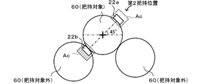
- first to fourth holding positions are set as holding positions as shown in FIG.
- the predetermined angle at which the rotational symmetry appears is set to 45 °. Therefore, the gripping angle that the line segment (dotted line in FIG. 7) connecting the centers of the pair of claws 22a and 22b forms with the reference line BL (horizontal line in FIG. 7) is 0 ° at the first gripping position, and the second gripping The position is 45 °, the third holding position is 90 °, and the fourth holding position is 135 °.
- the holding angle is 180 °
- the holding position is rounded because it overlaps the first holding position.
- the initial gripping position is assumed to be set to the first gripping position.
- the non-interference gripping position is a gripping position where there is no obstacle that interferes with the gripping operation of the claws 22a and 22b, that is, a gripping position where there is no obstacle in the chuck movable range Ac of the claws 22a and 22b.
- the obstacle include a workpiece other than the object to be gripped and a peripheral wall of the supply box 14. This determination is performed based on the candidate position and the image captured by the camera 23.
- the CPU 51 controls the transfer robot 20 so that the workpiece is held at the non-interference holding position (S190), and then the predetermined mounting of the storage box 32 on the tray 30 is performed.
- the transfer robot 20 is controlled so that the work is placed at the placement position (S200).
- the CPU 51 updates the candidate position (S160), and determines whether or not the candidate position after update has made a round (S170).
- the workpiece is a circular plate 60
- the candidate position is not a non-interference gripping position
- the gripping position is rotated counterclockwise by a predetermined angle 45 ° at which rotational symmetry appears from the gripping position set at the candidate position Is set to the next candidate position. Therefore, if the first gripping position which is the first candidate position is not the non-interference gripping position, the next candidate position is set to the second gripping position, and the next candidate position is the third gripping position, and further next The candidate position of is set to the fourth grip position.
- the candidate position next to the fourth grip position overlaps the first grip position and goes around. If it is determined in S170 that the candidate position after update has not made a round, the CPU 51 returns to S150 again to determine whether the candidate position after update is a non-interference grip position. On the other hand, if the candidate position after updating has made a round in S170, the CPU 51 skips gripping of the workpiece to be gripped (step S180).
- the circular plate 60 not to be held is in contact with the left and right diagonally below the circular plate 60 to be held (FIGS. 8 to 10).
- the first gripping position as shown in FIG. 8
- the circular plate 60 outside the gripping object obliquely below the right interferes with the chuck movable range Ac of the claw 22 a (see hatching). Therefore, it is determined that the first grip position is not the non-interference grip position.
- the second gripping position as shown in FIG. 9, the circular plate 60 other than the gripping target obliquely below the left interferes with the chuck movable range Ac of the claw 22b (see hatching). Therefore, it is determined that the second holding position is not the non-interference holding position as well.
- the third grip position is determined to be the non-interference grip position.
- the CPU 51 determines whether all workpieces shown in the image have been set as gripping targets (S210). If a workpiece not set as a gripping target still remains, the CPU 51 sets one of the remaining workpieces as a gripping target (S220), and repeats the processing from S140. If all workpieces shown in the image at S210 have been set as gripping targets, the CPU 51 ends the workpiece transfer processing routine.
- the bottom of the supply box 14 may be divided into a plurality of images and copied, and the above-described work transfer processing routine may be executed for each image. Good.
- the mechanical chuck 22 of the present embodiment corresponds to the chuck member of the present disclosure
- the supply box 14 corresponds to the storage device
- the camera 23 corresponds to the imaging device
- the control device 50 corresponds to the control device.
- an example of the gripping position search method of the present disclosure is also clarified.
- the positional relationship between the claws 22a and 22b and the workpiece when gripping the workpiece to be gripped at the initial gripping position is the other gripping positions (second to fourth grips)
- the positional relationship between the claws 22a and 22b and the workpiece when gripping the workpiece to be gripped at the position) is the same. This is because each gripping position is obtained by rotating the gripping position immediately before by a predetermined angle at which the rotational symmetry of the rotationally symmetric figure of the workpiece appears. Therefore, even if the workpiece to be gripped is interfered by the obstacle at the initial gripping position, the workpiece may not be interfered at the next gripping position, and the probability of gripping becomes improved. Therefore, the workpiece to be gripped can be gripped efficiently.
- a workpiece outside the gripping target and a component (for example, a peripheral wall) of the supply box 14 are illustrated. This is because a workpiece not to be gripped may be in contact with, close to, or overlapping with a workpiece to be gripped, and the peripheral wall of the supply box 14 may be in contact with or close to the workpiece to be gripped It is because there is.
- the candidate position is a non-interference gripping position
- an obstacle within the chuck movable range Ac set based on the size of the mechanical chuck 22, the tip shape (shape of the claws 22a and 22b) and the movable range It is determined that the candidate position is a non-interference holding position if there is no. Therefore, it is possible to appropriately determine whether the candidate position is the non-interference holding position.
- the circular plate 60 is illustrated as a work in describing the work transfer processing routine, but the washer 70 shown in FIG. 5 may be used as a work.
- the gripping position shown in FIG. 5A or 5B is adopted, and the predetermined angle at which the rotational property appears is, for example, 90 °, and the gripping angle 0 ° is the first gripping position, and the gripping angle 90 ° is the second gripping position.
- the work transfer process can be performed in the same manner as the circular plate 60 described above.
- a regular hexagonal plate or a nut may be used as the work.
- the gripping angle 0 ° is the first gripping position
- the gripping angle 60 ° is the second gripping position
- the gripping angle 120 ° is the third gripping position.
- the work transfer process can be performed in the same manner as the plate 60.
- the non-interference holding position may be searched again by using the holding position of FIG. 5B. This further increases the probability that the workpiece to be gripped can be gripped.
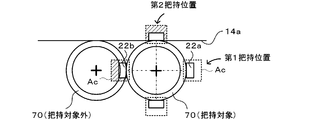
- the washer 70 on the right side of the two washers 70 captured in the image is the grip target, and the washer 70 other than the grip target is in contact with it. Indicates the case of contact. In this case, as shown in FIG. 11, when the gripping position shown in FIG.
- the washer 70 not to be gripped interferes with the chuck movable range Ac at the first gripping position and the peripheral wall of the supply box 14 at the second gripping position. Interferes with the chuck movable range Ac, so there is no non-interference holding position.
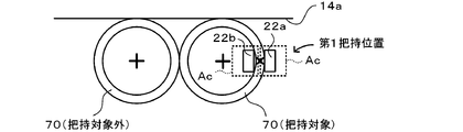
- the gripping position shown in FIG. 5B when the gripping position shown in FIG. 5B is adopted, neither the washer 70 outside the gripping target in the first gripping position nor the peripheral wall 14a of the supply box 14 interferes with the chuck movable range Ac. The position becomes the non-interference grip position and can be gripped.
- the CPU 51 determines that the candidate position is the non-interference holding position unless the workpiece other than the gripping target overlaps the chuck movable range Ac of the mechanical chuck 22 at the candidate position. Not limited to. For example, even if a workpiece not to be gripped overlaps the chuck movable range Ac of the mechanical chuck 22 at the candidate position, the CPU 51 calculates an interference area ratio obtained by dividing the overlapped area by the area of the check movable range Ac, The determination may be performed using the interference area rate.
- the CPU 51 determines that the candidate position is the non-interference holding position if the interference area ratio is equal to or less than the predetermined threshold (or less than the threshold), and indicates the candidate position if it exceeds the threshold (or more than the threshold). It may be determined that it is not the non-interference holding position.
- the threshold value may be set to a value at which the mechanical chuck 22 can grip the workpiece by an experiment or the like.
- the search for the non-interference holding position (S140 to S170) is executed in the work placement process for actually placing the work from the supply box 14 to the accommodation box 32 has been exemplified.
- a search for a non-interference holding position may be performed by simulation.
- the chuck movable range Ac of various types of mechanical chucks 22 different in size and tip shape is modeled and registered in advance in the storage unit 52, and the CPU 51 performs simulation to find out a non-interference holding position.
- the operator may be notified of a chuck member 22 having a high grip height ratio. For example, when the mechanical chuck 22 capable of employing the gripping position shown in FIG.
- the CPU 51 recommends the small mechanical chuck 22 as a chucking member with high gripping efficiency. By so doing, it is possible to find out a mechanical chuck 22 capable of gripping a workpiece to be gripped among a plurality of types of mechanical chucks 22.
- the non-interference holding position of the mechanical chuck 22 is searched is illustrated in the embodiment described above, an adsorption nozzle or an electromagnet may be used instead of the mechanical chuck 22.
- the non-interference holding position may be searched based on the fact that another workpiece does not overlap the portion where the suction nozzle is in contact with the workpiece.
- the range covered by the magnetic force of the electromagnet may be set as an interference check area, and the non-interference holding position may be searched based on the absence of another work in the area.
- the working machine of the present disclosure may be configured as follows.
- the obstacle may be a component other than the grip target component and / or a component of the storage device.
- Parts other than the parts to be gripped may be in contact with or overlap with the parts to be gripped, and components of the storage device (for example, a wall or the like) may be in contact with the parts to be gripped. It is easy to become an obstacle of
- control device is configured to move the chuck, which is set based on the size and / or the tip shape of the chuck member and the movable range when determining whether the candidate position is the non-interference holding position. If the obstacle does not exist in the range, it may be determined that the candidate position is the non-interference holding position. In this way, it is possible to appropriately determine whether the candidate position is a non-interference holding position.
- control device may skip the gripping of the gripping target component if the non-interference gripping position is not found even if the candidate position makes one round around the rotationally symmetric figure. Good. In this case, it is possible to suppress the decrease in the gripping efficiency on the contrary by trying to grip the gripping target component in which any gripping position interferes with the obstacle.
- the entire one surface of the object to be gripped is the rotationally symmetric figure, and the gripping positions may be two mutually opposing points on the outer periphery of the rotationally symmetric figure.
- the one surface of the object to be gripped is annular, and both the inner peripheral shape and the outer peripheral shape are the rotationally symmetric figure, and the gripping positions are two points facing each other on the outer periphery of the rotationally symmetric figure Alternatively, it may be one point on the outer periphery of the rotationally symmetric figure and one point on the inner periphery opposite thereto.
- the grasping position search method of the present disclosure may be configured as follows.
- step (b) in determining whether the candidate position is the non-interference holding position, setting is performed based on the size and / or tip shape of the chuck member and the movable range. If the obstacle does not exist within the chuck movable range, it may be determined that the candidate position is the non-interference holding position. In this way, it is possible to appropriately determine whether the candidate position is a non-interference holding position.
- the chuck movable range is registered in advance in the storage unit for each of the various types of check members having different sizes and / or tip shapes, and in the step (b), the grasping position is If the non-interference holding position can not be found even after one rotation around the rotationally symmetric figure, the search processing is performed by calling the chuck movable range of another chuck member different in type from the chuck member from the storage unit If the non-interference holding position is found for the other chuck member, the other chuck member may be selected as a chuck member with high gripping efficiency. In this way, it is possible to find out a chuck member capable of gripping the grip target component among various types of chuck members having different sizes and / or tip shapes.
- the present invention is applicable to various industries that carry out work to transfer work.
Landscapes
- Engineering & Computer Science (AREA)
- Human Computer Interaction (AREA)
- Robotics (AREA)
- Mechanical Engineering (AREA)
- Manipulator (AREA)
Abstract
L'invention concerne un engin de chantier comprenant : un élément de mandrin qui saisit par serrage, en tant que position de préhension, deux points qui s'opposent l'un à l'autre sur une forme symétrique en rotation d'une pièce devant être saisie qui a au moins une face qui est une forme symétrique en rotation ; un dispositif de stockage qui stocke une pluralité de pièces comprenant la pièce à saisir ; un dispositif d'imagerie qui capture, à partir de ce qui précède, une image de la pluralité de pièces stockées dans le dispositif de stockage ; et un dispositif de commande qui définit une position de préhension par défaut prédéfinie en tant que position candidate et détermine, sur la base de la position candidate et de l'image capturée par le dispositif d'imagerie, si la position candidate est une position de préhension n'interférant pas sans obstacle pour interférer avec l'action de préhension de l'élément de mandrin, et lorsque la position candidate n'est pas une position de préhension n'interférant pas, définit, en tant que position candidate, la position de préhension suivante obtenue par rotation de la position de préhension d'un angle prescrit de telle sorte que la symétrie rotationnelle de la forme symétrique en rotation de la pièce à saisir se manifeste et détermine, si la position candidate est une position de préhension n'interférant pas.
Priority Applications (2)
| Application Number | Priority Date | Filing Date | Title |
|---|---|---|---|
| JP2019556041A JP6915085B2 (ja) | 2017-11-24 | 2017-11-24 | 作業機および把持位置探索方法 |
| PCT/JP2017/042154 WO2019102575A1 (fr) | 2017-11-24 | 2017-11-24 | Engin de chantier et procédé de recherche de position de préhension |
Applications Claiming Priority (1)
| Application Number | Priority Date | Filing Date | Title |
|---|---|---|---|
| PCT/JP2017/042154 WO2019102575A1 (fr) | 2017-11-24 | 2017-11-24 | Engin de chantier et procédé de recherche de position de préhension |
Publications (1)
| Publication Number | Publication Date |
|---|---|
| WO2019102575A1 true WO2019102575A1 (fr) | 2019-05-31 |
Family
ID=66631937
Family Applications (1)
| Application Number | Title | Priority Date | Filing Date |
|---|---|---|---|
| PCT/JP2017/042154 WO2019102575A1 (fr) | 2017-11-24 | 2017-11-24 | Engin de chantier et procédé de recherche de position de préhension |
Country Status (2)
| Country | Link |
|---|---|
| JP (1) | JP6915085B2 (fr) |
| WO (1) | WO2019102575A1 (fr) |
Cited By (1)
| Publication number | Priority date | Publication date | Assignee | Title |
|---|---|---|---|---|
| JP7505674B2 (ja) | 2021-02-01 | 2024-06-25 | 国立研究開発法人農業・食品産業技術総合研究機構 | ピッキングシステム |
Citations (4)
| Publication number | Priority date | Publication date | Assignee | Title |
|---|---|---|---|---|
| JP2008272886A (ja) * | 2007-04-27 | 2008-11-13 | Nissan Motor Co Ltd | 把持候補位置選出装置、把持候補位置選出方法、把持経路生成装置、および把持経路生成方法 |
| JP2011073066A (ja) * | 2009-09-29 | 2011-04-14 | Canon Inc | 物体把持制御方法及び装置 |
| JP2011167815A (ja) * | 2010-02-19 | 2011-09-01 | Ihi Corp | 物体認識ロボットシステム |
| JP2013111696A (ja) * | 2011-11-29 | 2013-06-10 | Seiko Epson Corp | 把持ロボット、制御装置、制御方法、及びプログラム |
Family Cites Families (1)
| Publication number | Priority date | Publication date | Assignee | Title |
|---|---|---|---|---|
| JP5788460B2 (ja) * | 2013-11-05 | 2015-09-30 | ファナック株式会社 | バラ積みされた物品をロボットで取出す装置及び方法 |
-
2017
- 2017-11-24 JP JP2019556041A patent/JP6915085B2/ja active Active
- 2017-11-24 WO PCT/JP2017/042154 patent/WO2019102575A1/fr active Application Filing
Patent Citations (4)
| Publication number | Priority date | Publication date | Assignee | Title |
|---|---|---|---|---|
| JP2008272886A (ja) * | 2007-04-27 | 2008-11-13 | Nissan Motor Co Ltd | 把持候補位置選出装置、把持候補位置選出方法、把持経路生成装置、および把持経路生成方法 |
| JP2011073066A (ja) * | 2009-09-29 | 2011-04-14 | Canon Inc | 物体把持制御方法及び装置 |
| JP2011167815A (ja) * | 2010-02-19 | 2011-09-01 | Ihi Corp | 物体認識ロボットシステム |
| JP2013111696A (ja) * | 2011-11-29 | 2013-06-10 | Seiko Epson Corp | 把持ロボット、制御装置、制御方法、及びプログラム |
Non-Patent Citations (1)
| Title |
|---|
| KIMURA, NOBUTAKA ET AL.: "Gripping Operation Planning Methods Including Graspless Manipulation for Mobile Work Robots", THE 32RD ANNUAL CONFERENCE OF THE ROBOTICS SOCIETY OF JAPAN, 4 September 2014 (2014-09-04), pages 1780 - 1783 * |
Cited By (1)
| Publication number | Priority date | Publication date | Assignee | Title |
|---|---|---|---|---|
| JP7505674B2 (ja) | 2021-02-01 | 2024-06-25 | 国立研究開発法人農業・食品産業技術総合研究機構 | ピッキングシステム |
Also Published As
| Publication number | Publication date |
|---|---|
| JP6915085B2 (ja) | 2021-08-04 |
| JPWO2019102575A1 (ja) | 2020-10-22 |
Similar Documents
| Publication | Publication Date | Title |
|---|---|---|
| CN110497401B (zh) | 取出散装的工件的机器人系统以及机器人系统的控制方法 | |
| JP6734402B2 (ja) | 作業機 | |
| CN114559428B (zh) | 用于提供动态机器人控制系统的系统和方法 | |
| EP1589483B1 (fr) | Système de saisie d'objets | |
| JP4938115B2 (ja) | ワーク取出し装置およびワーク取出し方法 | |
| US20120165986A1 (en) | Robotic picking of parts from a parts holding bin | |
| JP7163506B2 (ja) | 作業ロボットおよび作業システム | |
| US20180215035A1 (en) | Robot and method of controlling the same | |
| JP2006035397A (ja) | 搬送ロボットシステム | |
| JP5522298B2 (ja) | ビンピッキングシステム | |
| JP2017513727A (ja) | 目標物の自動把持方法および設備 | |
| JP2011000685A (ja) | ビンピッキングシステム | |
| JP6322959B2 (ja) | ロボット、ロボットシステム、及びロボット制御装置 | |
| JP2016147327A (ja) | 位置及び姿勢の変換演算機能を備えたワーク取出しロボットシステム、及びワーク取出し方法 | |
| JP7197653B2 (ja) | 画像処理装置 | |
| JP5535884B2 (ja) | ワーク取り出し方法 | |
| CN113858188A (zh) | 工业机器人的抓取方法和设备、计算机存储介质以及工业机器人 | |
| WO2019102575A1 (fr) | Engin de chantier et procédé de recherche de position de préhension | |
| JP6154130B2 (ja) | 電子部品装着装置及び電子部品装着方法 | |
| JP2019501033A (ja) | 異なる保管領域に置かれる部品から部品のバッチを構成するための方法および設備 | |
| JP2000263480A (ja) | ビンピッキング装置 | |
| KR101197125B1 (ko) | 물체 파지 시스템 및 물체 파지 방법 | |
| CN111278612B (zh) | 元件移载装置 | |
| US11485015B2 (en) | System for eliminating interference of randomly stacked workpieces | |
| WO1996041705A1 (fr) | Procede de prevention des perturbations concernant des robots industriels |
Legal Events
| Date | Code | Title | Description |
|---|---|---|---|
| 121 | Ep: the epo has been informed by wipo that ep was designated in this application |
Ref document number: 17932919 Country of ref document: EP Kind code of ref document: A1 |
|
| ENP | Entry into the national phase |
Ref document number: 2019556041 Country of ref document: JP Kind code of ref document: A |
|
| NENP | Non-entry into the national phase |
Ref country code: DE |
|
| 122 | Ep: pct application non-entry in european phase |
Ref document number: 17932919 Country of ref document: EP Kind code of ref document: A1 |