WO2019102575A1 - Work machine and gripping position search method - Google Patents
Work machine and gripping position search method Download PDFInfo
- Publication number
- WO2019102575A1 WO2019102575A1 PCT/JP2017/042154 JP2017042154W WO2019102575A1 WO 2019102575 A1 WO2019102575 A1 WO 2019102575A1 JP 2017042154 W JP2017042154 W JP 2017042154W WO 2019102575 A1 WO2019102575 A1 WO 2019102575A1
- Authority
- WO
- WIPO (PCT)
- Prior art keywords
- gripping
- interference
- candidate
- candidate position
- rotationally symmetric
- Prior art date
Links
Images


Classifications
-
- B—PERFORMING OPERATIONS; TRANSPORTING
- B25—HAND TOOLS; PORTABLE POWER-DRIVEN TOOLS; MANIPULATORS
- B25J—MANIPULATORS; CHAMBERS PROVIDED WITH MANIPULATION DEVICES
- B25J13/00—Controls for manipulators
- B25J13/08—Controls for manipulators by means of sensing devices, e.g. viewing or touching devices
Abstract
This work machine comprises: a chuck member that grips by clamping, as a gripping position, two points that oppose each other on a rotationally symmetrical shape of a part to be gripped that has at least one face that is a rotationally symmetrical shape; a storage device that stores a plurality of parts including the part to be gripped; an imaging device that captures, from above, an image of the plurality of parts stored in the storage device; and a control device that sets a preset default gripping position as a candidate position and determines, on the basis of the candidate position and the image captured by the imaging device, whether the candidate position is a non-interfering gripping position without an obstacle to interfere with the gripping action of the chuck member, and when the candidate position is not a non-interfering gripping position, sets, as a candidate position, the next gripping position obtained by rotating the gripping position by a prescribed angle so that the rotational symmetry of the rotationally symmetrical shape of the part to be gripped manifests and determines, again, whether the candidate position is a non-interfering gripping position.
Description
本明細書は、作業機および把持位置探索方法を開示する。
This specification discloses a work machine and a gripping position search method.
従来より、向きや姿勢が不揃いな状態で供給された複数の部品(対象物)の中から一の部品を採取する作業機が提案されている(例えば、特許文献1参照)。この作業機では、供給された複数の部品をカメラで撮像し、撮像した画像を処理して特定姿勢の部品を選び、選んだ部品を吸着ノズルで吸引することで採取して、所定姿勢に変換させるものとしている。
2. Description of the Related Art Conventionally, a working machine has been proposed that extracts one part from among a plurality of parts (objects) supplied in a state in which the orientation and attitude are not uniform (see, for example, Patent Document 1). In this work machine, a plurality of supplied parts are imaged by a camera, the imaged image is processed to select a part with a specific posture, and the selected part is collected by suction with a suction nozzle and converted into a predetermined posture It is supposed to
ところで、このような作業機において、部品同士が重なった状態となっているなど、部品を採取する際に他の部品が干渉する位置にある場合がある。その場合、作業機は、選んだ部品を適切に採取することが困難となり、採取効率が低下することがある。
By the way, in such a working machine, there may be a position where other parts interfere with each other when picking up a part, such as parts overlapping each other. In such a case, it may be difficult for the working machine to properly pick the selected part, which may lower the collection efficiency.
本開示の作業機および把持位置探索方法は、把持対象部品が他の部品などの障害物によって干渉されていたとしても把持対象部品を効率よく把持することを主目的とする。
The work machine and the gripping position search method of the present disclosure have as a main object to efficiently grip the gripping target part even if the gripping target part is interfered by an obstacle such as another part.
本開示の作業機は、
少なくとも1つの面が回転対称図形である把持対象部品のうち前記回転対称図形の互いに対向する2点を把持位置として挟んで把持するチャック部材と、
前記把持対象部品を含む複数の部品を貯留する貯留装置と、
前記貯留装置に貯留された前記複数の部品を上方から撮像する撮像装置と、
予め定められた初期の前記把持位置を候補位置に設定し、前記候補位置と前記撮像装置によって撮像された画像とに基づいて前記候補位置が前記チャック部材の把持動作を干渉する障害物のない不干渉把持位置か否かを判定し、前記候補位置が前記不干渉把持位置でなかったならば、前記把持対象部品の前記回転対称図形の回転対称性が現れる所定角度だけ前記把持位置を回転させて得られる次の前記把持位置を前記候補位置に設定し、再度、前記候補位置が前記不干渉把持位置か否かを判定する、という探索処理を前記不干渉把持位置が見つかるまで繰り返し、前記不干渉把持位置で前記把持対象部品を把持するよう前記チャック部材を制御する制御装置と、
を備えるものである。 The working machine of the present disclosure is
A chucking member for holding, as a gripping position, two mutually opposing points of the rotationally symmetric figure among gripping target parts of which at least one surface is a rotationally symmetric figure;
A storage device for storing a plurality of parts including the gripping target part;
An imaging device for imaging the plurality of components stored in the storage device from above;
The predetermined initial gripping position is set as a candidate position, and the candidate position interferes with the gripping operation of the chuck member based on the candidate position and the image captured by the imaging device. It is determined whether or not it is an interference gripping position, and if the candidate position is not the non-interference gripping position, the gripping position is rotated by a predetermined angle at which the rotational symmetry of the rotationally symmetric figure of the gripping target component appears. The next grasping position to be obtained is set as the candidate position, and the search process of determining again whether the candidate position is the non-interference holding position is repeated until the non-interference holding position is found, the non-interference A control device that controls the chuck member to grip the gripping target component at a gripping position;
Is provided.
この作業機では、予め定められた初期の把持位置を候補位置に設定し、その候補位置と、貯留装置に貯留された把持対象部品を含む複数の部品を上方から撮像した画像とに基づいて、候補位置がチャック部材の把持動作を干渉する障害物のない不干渉把持位置か否かを判定する。そして、その候補位置が不干渉把持位置でなかったならば、把持対象部品の回転対称図形の回転対称性が現れる所定角度だけ把持位置を回転させて得られる次の把持位置を候補位置に設定し、再度、候補位置が不干渉把持位置か否かを判定する、という探索処理を不干渉把持位置が見つかるまで繰り返す。ここで、初期の把持位置で把持対象部品を把持するときのチャック部材と把持対象部品との位置関係は、他の把持位置で把持対象部品を把持するときのチャック部材と把持対象部品との位置関係と同じになる。各把持位置は、把持対象部品の回転対称図形の回転対称性が現れる所定角度だけその直前の把持位置を回転させて得られるものだからである。この作業機によれば、初期の把持位置で把持対象部品が障害物によって干渉されていたとしても、次の把持位置で干渉されないことがあり、把持可能となる確率が向上する。したがって、把持対象部品を効率よく把持することができる。
In this work machine, a predetermined initial gripping position is set as a candidate position, and based on the candidate position and an image obtained by imaging a plurality of parts including a gripping target component stored in the storage device from above, It is determined whether the candidate position is a non-interference holding position without an obstacle that interferes with the holding operation of the chuck member. Then, if the candidate position is not a non-interference gripping position, the next gripping position obtained by rotating the gripping position by a predetermined angle at which the rotational symmetry of the rotationally symmetric figure of the gripping target part appears is set as the candidate position. The search process of determining again whether or not the candidate position is the non-interference holding position is repeated until the non-interference holding position is found. Here, the positional relationship between the chuck member and the gripping target component when gripping the gripping target component at the initial gripping position is the position of the chuck member and the gripping target component when gripping the gripping target component at another gripping position. It will be the same as the relationship. This is because each gripping position is obtained by rotating the gripping position immediately before it by a predetermined angle at which the rotational symmetry of the rotationally symmetric figure of the gripping target part appears. According to this work machine, even if the gripping target component is interfered by the obstacle at the initial gripping position, it may not be interfered at the next gripping position, and the probability of being grippable is improved. Therefore, the gripping target component can be gripped efficiently.
本開示の把持位置探索方法は、
少なくとも1つの面が回転対称図形である把持対象部品のうち前記回転対称図形の互いに対向する2点を把持位置として挟んで把持するチャック部材を制御する際に用いられる把持位置探索方法であって、
(a)貯留装置に貯留された前記把持対象部品を含む複数の部品を上方から撮像した画像を取得するステップと、
(b)予め定められた初期の前記把持位置を候補位置に設定し、前記候補位置と前記ステップ(a)で取得した画像とに基づいて前記候補位置が前記チャック部材の把持動作を干渉する障害物のない不干渉把持位置か否かを判定し、前記候補位置が前記不干渉把持位置でなかったならば、前記把持対象部品の前記回転対称図形の回転対称性が現れる所定角度だけ前記把持位置を回転させて得られる次の前記把持位置を前記候補位置に設定し、再度、前記候補位置が前記不干渉把持位置か否かを判定する、という探索処理を前記不干渉把持位置が見つかるまで繰り返すステップと、
を含むものである。 The grip position search method of the present disclosure is
A gripping position search method used when controlling a chuck member that grips and holds two mutually opposing points of the rotationally symmetric figure among the gripping target parts having at least one surface that is a rotationally symmetric figure as gripping positions,
(A) acquiring an image obtained by imaging a plurality of parts including the gripping target part stored in a storage device from above;
(B) An obstacle in which the candidate position interferes with the gripping operation of the chuck member based on the candidate position and the image acquired in step (a), with the predetermined initial gripping position set as the candidate position It is determined whether or not the object is a non-interference holding position, and if the candidate position is not the non-interference holding position, the holding position is a predetermined angle at which the rotational symmetry of the rotationally symmetric figure of the object to be held appears. Is set as the candidate position, and it is determined again whether or not the candidate position is the non-interference holding position until the non-interference holding position is found. Step and
Is included.
この把持位置探索方法では、予め定められた初期の把持位置を候補位置に設定し、その候補位置と、貯留装置に貯留された把持対象部品を含む複数の部品を上方から撮像した画像とに基づいて、候補位置がチャック部材の把持動作を干渉する障害物のない不干渉把持位置か否かを判定する。そして、その候補位置が不干渉把持位置でなかったならば、把持対象部品の回転対称図形の回転対称性が現れる所定角度だけ把持位置を回転させて得られる次の把持位置を候補位置に設定し、再度、候補位置が不干渉把持位置か否かを判定する、という探索処理を不干渉把持位置が見つかるまで繰り返す。ここで、初期の把持位置で把持対象部品を把持するときのチャック部材と把持対象部品との位置関係は、他の把持位置で把持対象部品を把持するときのチャック部材と把持対象部品との位置関係と同じになる。各把持位置は、把持対象部品の回転対称図形の回転対称性が現れる所定角度だけその直前の把持位置を回転させて得られるものだからである。この把持位置探索方法によれば、初期の把持位置で把持対象部品が障害物によって干渉されていたとしても、次の把持位置で干渉されないことがある。したがって、把持対象部品を把持可能な把持位置が見つかる確率が向上する。
In this gripping position search method, a predetermined initial gripping position is set as a candidate position, and the candidate position is based on an image obtained by imaging a plurality of parts including the gripping target component stored in the storage device from above Then, it is determined whether the candidate position is a non-interference holding position without an obstacle that interferes with the holding operation of the chuck member. Then, if the candidate position is not a non-interference gripping position, the next gripping position obtained by rotating the gripping position by a predetermined angle at which the rotational symmetry of the rotationally symmetric figure of the gripping target part appears is set as the candidate position. The search process of determining again whether or not the candidate position is the non-interference holding position is repeated until the non-interference holding position is found. Here, the positional relationship between the chuck member and the gripping target component when gripping the gripping target component at the initial gripping position is the position of the chuck member and the gripping target component when gripping the gripping target component at another gripping position. It will be the same as the relationship. This is because each gripping position is obtained by rotating the gripping position immediately before it by a predetermined angle at which the rotational symmetry of the rotationally symmetric figure of the gripping target part appears. According to this gripping position search method, even if the gripping target component is interfered by the obstacle at the initial gripping position, it may not be interfered at the next gripping position. Therefore, the probability of finding the gripping position at which the gripping target component can be gripped is improved.
次に、本開示の発明を実施するための形態について説明する。
Next, an embodiment of the present disclosure will be described.
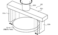
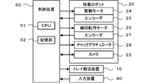
図1はワーク移載システム10の構成図、図2はメカチャック22の斜視図、図3は制御装置50の電気的な接続関係を示す説明図である。なお、ワーク移載システム10における、左右方向(X軸)、前後方向(Y軸)および上下方向(Z軸)は、図1に示した通りとして以下説明する。
FIG. 1 is a block diagram of the work transfer system 10, FIG. 2 is a perspective view of the mechanical chuck 22, and FIG. 3 is an explanatory view showing an electrical connection of the control device 50. As shown in FIG. The lateral direction (X axis), the longitudinal direction (Y axis), and the vertical direction (Z axis) in the workpiece transfer system 10 will be described below as shown in FIG.
本実施形態のワーク移載システム10は、図1に示すように、供給ボックス14内のワーク(部品)を採取して、トレイ30上の収容ボックス32内に載置したりトレイ30上に載置したりするシステムである。このワーク移載システム10は、複数(例えば3個)の供給ボックス14と、トレイ搬送装置16と、移載ロボット20と、制御装置50(図3参照)とを備える。供給ボックス14には、図示しない供給ロボットや供給コンベア、作業者などからワークが投入される。供給ボックス14内の各ワークは、位置や向き、姿勢などがバラバラであり、ワーク同士の重なりも生じる状態となっている。トレイ搬送装置16は、前後一対のコンベアベルトを駆動してトレイ30を左右方向に搬送する。トレイ搬送装置16と移載ロボット20は、作業台11上に設置されている。トレイ30上の収容ボックス32は、上方が開放した箱であり、トレイ30上に複数個(例えば3個)配置されている。この収容ボックス32は、例えば収容されるワークに応じたサイズとなっており、複数枚のワークを重ねて収容可能となっている。
As shown in FIG. 1, the workpiece transfer system 10 according to the present embodiment collects the workpieces (components) in the supply box 14 and places them in the storage box 32 on the tray 30 or places them on the tray 30. It is a system to place. The work transfer system 10 includes a plurality of (for example, three) supply boxes 14, a tray transfer device 16, a transfer robot 20, and a control device 50 (see FIG. 3). Work is input to the supply box 14 from a supply robot, a supply conveyor, a worker, etc. (not shown). The positions, orientations, postures, etc. of the works in the supply box 14 are disjointed, and the works overlap with each other. The tray transfer device 16 drives the pair of front and rear conveyor belts to transfer the tray 30 in the left-right direction. The tray transfer device 16 and the transfer robot 20 are installed on the work table 11. The accommodation box 32 on the tray 30 is a box opened at the top, and a plurality (for example, three) of the accommodation boxes 32 are arranged on the tray 30. The storage box 32 has a size corresponding to, for example, the work to be stored, and can stack and store a plurality of works.
移載ロボット20は、供給ボックス14内のワークを採取してトレイ30上(収容ボックス32を含む)に載置するためのロボットである。この移載ロボット20は、図1に示すように、垂直多関節型のロボットアーム21と、エンドエフェクタとしてのメカチャック22とを備える。ロボットアーム21は、複数のリンクと、各リンクを旋回可能に連結する複数の関節と、各関節を駆動する複数の駆動モータ24(図3参照)と、各関節の角度を検出する複数のエンコーダ25(図3参照)とを有する。なお、図3では、駆動モータ24とエンコーダ25とをそれぞれ1つずつ図示した。メカチャック22は、図2に示すように、ベースプレート22cの下面に開閉可能に取り付けられた一対の爪22a,22bを有している。一対の爪22a,22bは、チャックアクチュエータ28(図3参照)によって駆動されて開閉する。爪22a,22bの開位置を図2の実線で示し、閉位置を図2の1点鎖線で示す。ベースプレート22cの上面中央には、シャフト22dが取り付けられている。シャフト22dは、ベースプレート22c及び一対の爪22a,22bと共に軸回転用モータ26(図3参照)によって軸回転される。シャフト22dの回転角度は、エンコーダ27(図3参照)によって検出可能となっている。また、ロボットアーム21の先端リンクには、下方に位置する供給ボックス14内のワークなどを撮像して、ワークの位置や状態を認識するためのカメラ23も取り付けられている。
The transfer robot 20 is a robot for collecting the work in the supply box 14 and placing the work on the tray 30 (including the storage box 32). As shown in FIG. 1, the transfer robot 20 includes a vertical articulated robot arm 21 and a mechanical chuck 22 as an end effector. The robot arm 21 includes a plurality of links, a plurality of joints pivotably connecting the links, a plurality of drive motors 24 (see FIG. 3) driving the joints, and a plurality of encoders detecting angles of the joints 25 (see FIG. 3). In FIG. 3, one drive motor 24 and one encoder 25 are shown. As shown in FIG. 2, the mechanical chuck 22 has a pair of claws 22 a and 22 b attached to the lower surface of the base plate 22 c in an openable / closable manner. The pair of claws 22a and 22b are driven by the chuck actuator 28 (see FIG. 3) to open and close. The open position of the claws 22a and 22b is indicated by a solid line in FIG. 2, and the closed position is indicated by an alternate long and short dash line in FIG. A shaft 22d is attached to the center of the upper surface of the base plate 22c. The shaft 22d is axially rotated by a shaft rotation motor 26 (see FIG. 3) together with the base plate 22c and the pair of claws 22a and 22b. The rotation angle of the shaft 22d can be detected by the encoder 27 (see FIG. 3). In addition, a camera 23 is also attached to the tip link of the robot arm 21 for imaging a workpiece or the like in the supply box 14 located below and recognizing the position and the state of the workpiece.
制御装置50は、図3に示すように、CPU51を中心としたマイクロプロセッサとして構成されており、CPU51の他に、ROMやHDDなどの記憶部52を備える。制御装置50には、移載ロボット20のエンコーダ25,27、カメラ23および入力装置40などからの各種信号が入力される。制御装置50からは、移載ロボット20の駆動モータ24、軸回転用モータ26、チャックアクチュエータ28、カメラ23およびトレイ搬送装置16などへの各種制御信号が出力される。なお、作業者は、ワーク移載システム10への作業指示や供給ボックス14に投入したワークの種類などを、入力装置40を介して入力可能となっている。
As shown in FIG. 3, the control device 50 is configured as a microprocessor centering on the CPU 51, and includes a storage unit 52 such as a ROM or an HDD in addition to the CPU 51. Various signals from the encoders 25 and 27 of the transfer robot 20, the camera 23 and the input device 40 are input to the control device 50. The control device 50 outputs various control signals to the drive motor 24 of the transfer robot 20, the shaft rotation motor 26, the chuck actuator 28, the camera 23, the tray conveyance device 16, and the like. The operator can input, via the input device 40, a work instruction to the work transfer system 10, the type of work input to the supply box 14, and the like.
メカチャック22に把持されるワークは、少なくとも1つの面が回転対称図形のものである。回転対称図形としては、円や正n角形(nは3以上の整数、好ましくはnは4以上の偶数)などが挙げられる。円の場合、回転対称性が現れる角度は任意であり、正n角形の場合、回転対称性が現れる角度は360°/nかその倍数である。ワークとしては、円形プレート、ワッシャ(円形リング)、正六角形プレート、ナット(正六角形リング)などが挙げられる。円形プレートや正六角形プレートは、面全体が回転対称図形であり、ワッシャやナットは、環状であって内周形状と外周形状が共に回転対称図形である。
The workpiece held by the mechanical chuck 22 has at least one surface of rotational symmetry. Examples of rotationally symmetric figures include circles and n-gons (n is an integer of 3 or more, preferably n is an even number of 4 or more). In the case of a circle, the angle at which rotational symmetry appears is arbitrary, and in the case of a regular n-gon, the angle at which rotational symmetry appears is 360 ° / n or a multiple thereof. The work includes a circular plate, a washer (circular ring), a regular hexagonal plate, a nut (regular hexagonal ring) and the like. The circular plate and the regular hexagonal plate have a rotationally symmetric figure on the entire surface, and the washer and the nut have an annular shape, and both the inner circumferential shape and the outer circumferential shape are rotationally symmetric.
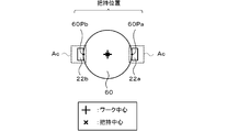
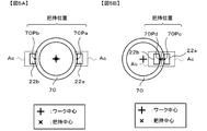
ワークが図4に示すように円形プレート60の場合、一対の爪22a,22bで挟んで把持する把持位置は円形プレート60の中心を挟んで対向する外周上の任意の2点60Pa,60Pbになる。このときの把持中心(2点60Pa,60Pbを結んだ線分の真ん中)は、ワークの中心(円形プレート60の中心)と一致する。ワークが図5に示すようにワッシャ70の場合、一対の爪22a,22bで挟んで把持する把持位置は2種類ある。1つめの把持位置は、図5Aのようにワッシャ70の中心を挟んで対向する外周上の任意の2点70Pa,70Pbである。このときの把持中心(2点70Pa,70Pbを結んだ線分の真ん中)は、ワークの中心(ワッシャ70の中心)と一致する。もう1つの把持位置は、図5Bに示すようにワッシャ70の外周上の任意の点70Pcと、その点70Pcからワッシャ70の中心まで引いた線が内周と交差する点70Pdの計2点である。このときの把持中心(2点70Pc,70Pdを結んだ線分の真ん中)は、ワークの中心(ワッシャ70の中心)からオフセットしている。図4及び図5において、爪22a,22bの周囲に示した点線領域は、チャック可動範囲Acを表す。チャック可動範囲Acは、爪22a,22bのサイズ、先端形状及び爪22a,22bの可動域に基づいて設定されている。
In the case where the work is a circular plate 60 as shown in FIG. 4, the holding positions held by the pair of claws 22 a and 22 b are arbitrary two points 60 Pa and 60 Pb on the outer periphery facing each other across the center of the circular plate 60. . The gripping center at this time (the middle of the line segment connecting the two points 60Pa and 60Pb) coincides with the center of the work (the center of the circular plate 60). When the work is a washer 70 as shown in FIG. 5, there are two types of gripping positions to be gripped and gripped by the pair of claws 22a and 22b. The first gripping position is arbitrary two points 70Pa and 70Pb on the outer periphery facing each other across the center of the washer 70 as shown in FIG. 5A. The gripping center at this time (the middle of the line segment connecting the two points 70Pa and 70Pb) coincides with the center of the work (the center of the washer 70). The other gripping position is a total of two points 70Pc on the outer periphery of the washer 70 and a point 70Pd at which the line drawn from the point 70Pc to the center of the washer 70 intersects the inner periphery as shown in FIG. 5B. is there. The gripping center at this time (the middle of the line segment connecting the two points 70Pc and 70Pd) is offset from the center of the work (the center of the washer 70). In FIG. 4 and FIG. 5, dotted regions shown around the claws 22a and 22b represent the chuck movable range Ac. The chuck movable range Ac is set based on the size of the claws 22a and 22b, the tip shape, and the movable range of the claws 22a and 22b.
次に、こうして構成された本実施形態のワーク移載システム10の動作について説明する。ここでは、ワークとして円形プレート60を例示しながら説明する。。図5は、ワーク移載処理の一例を示すフローチャートである。このルーチンは、制御装置50のCPU51により実行される。制御装置50のCPU51は、ワーク移載処理を開始すると、まず、今回移載するワークである円形プレート60に関する情報を記憶部52から読み出す(S100)。記憶部52には、予め円形プレート60に関する情報として円形プレート60の外径や回転中心の座標、把持位置、回転対称性が表れる所定角度(ここでは45°)などが記憶されている。
Next, the operation of the workpiece transfer system 10 of the present embodiment configured as described above will be described. Here, the circular plate 60 will be described as an example of the work. . FIG. 5 is a flowchart showing an example of the work transfer process. This routine is executed by the CPU 51 of the control device 50. When the work transfer process is started, the CPU 51 of the control device 50 first reads out information on the circular plate 60 which is a work to be transferred this time from the storage unit 52 (S100). In the storage unit 52, the outer diameter of the circular plate 60, the coordinates of the rotation center, the gripping position, a predetermined angle (here, 45 °) at which rotational symmetry appears, etc. are stored in advance as information on the circular plate 60.
次に、CPU51は、複数のワークが入っている供給ボックス14内の画像を上方から撮像し(S110)、撮像した画像に写っているワークを認識する(S120)。S120では、CPU51は、撮像した画像から色(画素値)や形状が円形プレート60に該当する領域を抽出することなどにより、円形プレート60を認識する。また、CPU51は、抽出した領域の大きさや形状から各円形プレート60が単独で存在しているか、隣接したり重なったりして存在しているかも認識可能である。次に、CPU51は、撮像した画像に写っているワークのうち一のワークを今回の把持対象に設定する(S130)。続いて、CPU51は、把持対象のワークの初期の把持位置を候補位置に設定する(S140)。
Next, the CPU 51 picks up an image in the supply box 14 containing a plurality of works from above (S110), and recognizes a work shown in the picked up image (S120). In S120, the CPU 51 recognizes the circular plate 60 by extracting an area in which the color (pixel value) or the shape corresponds to the circular plate 60 from the captured image. The CPU 51 can also recognize from the size and shape of the extracted area whether each circular plate 60 is present alone or adjacent or overlapped. Next, the CPU 51 sets one of the workpieces shown in the captured image as the current gripping target (S130). Subsequently, the CPU 51 sets an initial gripping position of the workpiece to be gripped as a candidate position (S140).
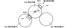
ワークが円形プレート60の場合、把持位置として図7に示すように第1~第4把持位置が設定されているものとする。図7では、回転対称性が表れる所定角度は45°に設定されている。そのため、一対の爪22a,22bの中心を結んだ線分(図7の1点鎖線)が基準線BL(図7の横線)となす把持角度は、第1把持位置では0°、第2把持位置では45°、第3把持位置では90°、第4把持位置では135°であり、把持角度が180°になると第1把持位置と重なるため把持位置が一巡したことになる。初期の把持位置は第1把持位置に設定されるものとする。
When the work is a circular plate 60, it is assumed that first to fourth holding positions are set as holding positions as shown in FIG. In FIG. 7, the predetermined angle at which the rotational symmetry appears is set to 45 °. Therefore, the gripping angle that the line segment (dotted line in FIG. 7) connecting the centers of the pair of claws 22a and 22b forms with the reference line BL (horizontal line in FIG. 7) is 0 ° at the first gripping position, and the second gripping The position is 45 °, the third holding position is 90 °, and the fourth holding position is 135 °. When the holding angle is 180 °, the holding position is rounded because it overlaps the first holding position. The initial gripping position is assumed to be set to the first gripping position.
次に、CPU51は、候補位置が不干渉把持位置か否かを判定する(S150)。不干渉把持位置とは、爪22a,22bの把持動作を干渉する障害物がない把持位置、すなわち爪22a,22bのチャック可動範囲Acに障害物がない把持位置である。障害物としては、把持対象以外のワークや供給ボックス14の周壁などが挙げられる。この判定は、候補位置とカメラ23によって撮像された画像とに基づいて行われる。候補位置が不干渉把持位置だったならば、CPU51は、その不干渉把持位置でワークが把持されるよう移載ロボット20を制御し(S190)、その後トレイ30上の収容ボックス32の所定の載置位置にそのワークが載置されるよう移載ロボット20を制御する(S200)。
Next, the CPU 51 determines whether or not the candidate position is a non-interference holding position (S150). The non-interference gripping position is a gripping position where there is no obstacle that interferes with the gripping operation of the claws 22a and 22b, that is, a gripping position where there is no obstacle in the chuck movable range Ac of the claws 22a and 22b. Examples of the obstacle include a workpiece other than the object to be gripped and a peripheral wall of the supply box 14. This determination is performed based on the candidate position and the image captured by the camera 23. If the candidate position is the non-interference holding position, the CPU 51 controls the transfer robot 20 so that the workpiece is held at the non-interference holding position (S190), and then the predetermined mounting of the storage box 32 on the tray 30 is performed. The transfer robot 20 is controlled so that the work is placed at the placement position (S200).
一方、候補位置が不干渉把持位置でなかったならば、CPU51は、候補位置を更新し(S160)、更新後の候補位置が一巡したか否かを判定する(S170)。ワークが円形プレート60の場合、候補位置が不干渉把持位置でなかったならば、その候補位置に設定された把持位置から回転対称性が表れる所定角度45°だけ反時計回りに回転させた把持位置を次の候補位置に設定する。そのため、最初の候補位置である第1把持位置が不干渉把持位置でなかったならば、次の候補位置は第2把持位置に設定され、その次の候補位置は第3把持位置、更にその次の候補位置は第4把持位置に設定される。第4把持位置の次の候補位置は第1把持位置と重なり一巡したことになる。S170で更新後の候補位置が一巡していなかったならば、CPU51は、再びS150に戻って、更新後の候補位置が不干渉把持位置か否かを判定する。一方、S170で更新後の候補位置が一巡していたならば、CPU51は、把持対象のワークの把持をスキップする(ステップS180)。
On the other hand, if the candidate position is not the non-interference grip position, the CPU 51 updates the candidate position (S160), and determines whether or not the candidate position after update has made a round (S170). When the workpiece is a circular plate 60, if the candidate position is not a non-interference gripping position, the gripping position is rotated counterclockwise by a predetermined angle 45 ° at which rotational symmetry appears from the gripping position set at the candidate position Is set to the next candidate position. Therefore, if the first gripping position which is the first candidate position is not the non-interference gripping position, the next candidate position is set to the second gripping position, and the next candidate position is the third gripping position, and further next The candidate position of is set to the fourth grip position. The candidate position next to the fourth grip position overlaps the first grip position and goes around. If it is determined in S170 that the candidate position after update has not made a round, the CPU 51 returns to S150 again to determine whether the candidate position after update is a non-interference grip position. On the other hand, if the candidate position after updating has made a round in S170, the CPU 51 skips gripping of the workpiece to be gripped (step S180).
例えば、撮像された画像において、把持対象の円形プレート60の左右斜め下に把持対象外の円形プレート60が接していた場合を考える(図8~図10)。第1把持位置では、図8に示すように、爪22aのチャック可動範囲Acに右斜め下の把持対象外の円形プレート60が干渉している(ハッチング参照)。そのため、第1把持位置は不干渉把持位置ではないと判定される。第2把持位置では、図9に示すように、爪22bのチャック可動範囲Acに左斜め下の把持対象外の円形プレート60が干渉している(ハッチング参照)。そのため、第2把持位置も不干渉把持位置ではないと判定される。第3把持位置では、図10に示すように、爪22a,22bのいずれのチャック可動範囲Acにも把持対象外の円形プレート60が干渉していない。そのため、第3把持位置は不干渉把持位置と判定される。
For example, it is assumed that in the captured image, the circular plate 60 not to be held is in contact with the left and right diagonally below the circular plate 60 to be held (FIGS. 8 to 10). In the first gripping position, as shown in FIG. 8, the circular plate 60 outside the gripping object obliquely below the right interferes with the chuck movable range Ac of the claw 22 a (see hatching). Therefore, it is determined that the first grip position is not the non-interference grip position. In the second gripping position, as shown in FIG. 9, the circular plate 60 other than the gripping target obliquely below the left interferes with the chuck movable range Ac of the claw 22b (see hatching). Therefore, it is determined that the second holding position is not the non-interference holding position as well. In the third gripping position, as shown in FIG. 10, the circular plate 60 not to be gripped does not interfere with any of the chuck movable ranges Ac of the claws 22a and 22b. Therefore, the third grip position is determined to be the non-interference grip position.
CPU51は、S180又はS200のあと、画像に写った全ワークを把持対象に設定したか否かを判定する(S210)。まだ把持対象に設定していないワークが残っていたならば、CPU51は、残っているワークのうちの一のワークを把持対象に設定し(S220)、S140以降の処理を繰り返す。S210で画像に写った全ワークを把持対象に設定済みだったならば、CPU51は、ワーク移載処理ルーチンを終了する。
After S180 or S200, the CPU 51 determines whether all workpieces shown in the image have been set as gripping targets (S210). If a workpiece not set as a gripping target still remains, the CPU 51 sets one of the remaining workpieces as a gripping target (S220), and repeats the processing from S140. If all workpieces shown in the image at S210 have been set as gripping targets, the CPU 51 ends the workpiece transfer processing routine.
なお、供給ボックス14の底面を一枚の画像で写すことができない場合には、供給ボックス14の底面を複数枚の画像に分けて写し、各画像について上述したワーク移載処理ルーチンを実行すればよい。
If the bottom of the supply box 14 can not be copied with one image, the bottom of the supply box 14 may be divided into a plurality of images and copied, and the above-described work transfer processing routine may be executed for each image. Good.
ここで、本実施形態の構成要素と本開示の構成要素との対応関係を明らかにする。本実施形態のメカチャック22が本開示のチャック部材に相当し、供給ボックス14が貯留装置に相当し、カメラ23が撮像装置に相当し、制御装置50が制御装置に相当する。なお、本実施形態では、移載ロボット20と制御装置50の動作を説明することにより、本開示の把持位置探索方法の一例も明らかにしている。
Here, the correspondence between the components of the present embodiment and the components of the present disclosure will be clarified. The mechanical chuck 22 of the present embodiment corresponds to the chuck member of the present disclosure, the supply box 14 corresponds to the storage device, the camera 23 corresponds to the imaging device, and the control device 50 corresponds to the control device. In the present embodiment, by describing the operations of the transfer robot 20 and the control device 50, an example of the gripping position search method of the present disclosure is also clarified.
以上説明した実施形態では、初期の把持位置(第1把持位置)で把持対象のワークを把持するときの爪22a,22bとワークとの位置関係は、他の把持位置(第2~第4把持位置)で把持対象のワークを把持するときの爪22a,22bとワークとの位置関係と同じになる。各把持位置は、ワークの回転対称図形の回転対称性が現れる所定角度だけその直前の把持位置を回転させて得られるものだからである。そのため、初期の把持位置で把持対象のワークが障害物によって干渉されていたとしても、次の把持位置で干渉されないことがあり、把持可能となる確率が向上する。したがって、把持対象のワークを効率よく把持することができる。
In the embodiment described above, the positional relationship between the claws 22a and 22b and the workpiece when gripping the workpiece to be gripped at the initial gripping position (first gripping position) is the other gripping positions (second to fourth grips) The positional relationship between the claws 22a and 22b and the workpiece when gripping the workpiece to be gripped at the position) is the same. This is because each gripping position is obtained by rotating the gripping position immediately before by a predetermined angle at which the rotational symmetry of the rotationally symmetric figure of the workpiece appears. Therefore, even if the workpiece to be gripped is interfered by the obstacle at the initial gripping position, the workpiece may not be interfered at the next gripping position, and the probability of gripping becomes improved. Therefore, the workpiece to be gripped can be gripped efficiently.
また、メカチャック22の把持動作を干渉する障害物として、把持対象外のワークや供給ボックス14の構成部材(例えば周壁)を例示した。これは、把持対象外のワークは把持対象のワークと接していたり接近していたり重なり合っていたりすることがあり、供給ボックス14の周壁は把持対象のワークと接していたり接近していたりすることがあるからである。
Further, as an obstacle that interferes with the gripping operation of the mechanical chuck 22, a workpiece outside the gripping target and a component (for example, a peripheral wall) of the supply box 14 are illustrated. This is because a workpiece not to be gripped may be in contact with, close to, or overlapping with a workpiece to be gripped, and the peripheral wall of the supply box 14 may be in contact with or close to the workpiece to be gripped It is because there is.
更に、候補位置が不干渉把持位置か否かを判定するにあたり、メカチャック22のサイズ、先端形状(爪22a,22bの形状)及び可動域に基づいて設定されたチャック可動範囲Ac内に障害物が存在しないならば候補位置が不干渉把持位置であると判定する。そのため、候補位置が不干渉把持位置か否かの判定を適切に行うことができる。
Furthermore, in determining whether or not the candidate position is a non-interference gripping position, an obstacle within the chuck movable range Ac set based on the size of the mechanical chuck 22, the tip shape (shape of the claws 22a and 22b) and the movable range It is determined that the candidate position is a non-interference holding position if there is no. Therefore, it is possible to appropriately determine whether the candidate position is the non-interference holding position.
更にまた、候補位置が把持対象のワークの回転対称図形の周りを一巡しても不干渉把持位置が見つからなかったならばそのワークの把持をスキップする。そのため、いずれの把持位置も障害物と干渉しているワークを把持しようとすることにより却って把持効率が低下するのを抑制することができる。
Furthermore, if the incoherent gripping position is not found even if the candidate position makes one round around the rotationally symmetric figure of the workpiece to be gripped, gripping of the workpiece is skipped. Therefore, it is possible to suppress the decrease in the gripping efficiency by trying to grip the workpiece in which any gripping position interferes with the obstacle.
なお、本発明は上述した実施形態に何ら限定されることはなく、本発明の技術的範囲に属する限り種々の態様で実施し得ることはいうまでもない。
It is needless to say that the present invention is not limited to the above-mentioned embodiment at all, and can be implemented in various modes within the technical scope of the present invention.
例えば、上述した実施形態では、ワーク移載処理ルーチンを説明するにあたり、ワークとして円形プレート60を例示したが、ワークとして図5に示したワッシャ70を用いてもよい。その場合、図5A又は図5Bに示した把持位置を採用して、回転性の現れる所定角度を例えば90°とし、把持角度0°を第1把持位置、把持角度90°を第2把持位置とすれば、上述した円形プレート60と同様にしてワーク移載処理を行うことができる。また、ワークとして、正六角形プレートやナットを用いてもよい。その場合、回転性の現れる所定角度を60°とし、把持角度0°を第1把持位置、把持角度60°を第2把持位置、把持角度120°を第3把持位置とすれば、上述した円形プレート60と同様にしてワーク移載処理を行うことができる。
For example, in the embodiment described above, the circular plate 60 is illustrated as a work in describing the work transfer processing routine, but the washer 70 shown in FIG. 5 may be used as a work. In that case, the gripping position shown in FIG. 5A or 5B is adopted, and the predetermined angle at which the rotational property appears is, for example, 90 °, and the gripping angle 0 ° is the first gripping position, and the gripping angle 90 ° is the second gripping position. Then, the work transfer process can be performed in the same manner as the circular plate 60 described above. In addition, a regular hexagonal plate or a nut may be used as the work. In that case, if the predetermined angle in which the rotational property appears is 60 °, the gripping angle 0 ° is the first gripping position, the gripping angle 60 ° is the second gripping position, and the gripping angle 120 ° is the third gripping position. The work transfer process can be performed in the same manner as the plate 60.
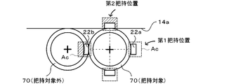
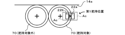
あるいは、図5Aの把持位置を採用して候補位置が一巡したあとも不干渉把持位置が見つからなかった場合、図5Bの把持位置を採用して再度不干渉把持位置を探索してもよい。こうすれば、把持対象のワークが把持可能となる確率がより高まる。例えば、図11及び図12に、画像に写った2つのワッシャ70のうち右側のワッシャ70が把持対象であり、それに把持対象外のワッシャ70が接しており、上側に供給ボックス14の周壁14aが接している場合を示す。この場合、図11のように、図5Aに示した把持位置を採用すると、第1把持位置では把持対象外のワッシャ70がチャック可動範囲Acに干渉し、第2把持位置では供給ボックス14の周壁がチャック可動範囲Acに干渉するため、不干渉把持位置は存在しないことになる。一方、図12のように、図5Bに示した把持位置を採用すると、第1把持位置では把持対象外のワッシャ70も供給ボックス14の周壁14aもチャック可動範囲Acに干渉しないため、第1把持位置が不干渉把持位置になり、把持可能となる。
Alternatively, if the non-interference holding position can not be found even after the candidate positions go around after adopting the holding position of FIG. 5A, the non-interference holding position may be searched again by using the holding position of FIG. 5B. This further increases the probability that the workpiece to be gripped can be gripped. For example, in FIG. 11 and FIG. 12, the washer 70 on the right side of the two washers 70 captured in the image is the grip target, and the washer 70 other than the grip target is in contact with it. Indicates the case of contact. In this case, as shown in FIG. 11, when the gripping position shown in FIG. 5A is adopted, the washer 70 not to be gripped interferes with the chuck movable range Ac at the first gripping position and the peripheral wall of the supply box 14 at the second gripping position. Interferes with the chuck movable range Ac, so there is no non-interference holding position. On the other hand, as shown in FIG. 12, when the gripping position shown in FIG. 5B is adopted, neither the washer 70 outside the gripping target in the first gripping position nor the peripheral wall 14a of the supply box 14 interferes with the chuck movable range Ac. The position becomes the non-interference grip position and can be gripped.
上述した実施形態では、CPU51は把持対象外のワークが候補位置にあるメカチャック22のチャック可動範囲Acと重ならなければその候補位置を不干渉保持位置であると判定したが、特にこの判定手法に限らない。例えば、把持対象外のワークが候補位置にあるメカチャック22のチャック可動範囲Acと重なっていたとしても、CPU51がその重なった面積をチェック可動範囲Acの面積で除した干渉面積率を算出し、その干渉面積率を用いて判定を行ってもよい。すなわち、CPU51は干渉面積率が予め定めた閾値以下(又は閾値未満)であればその候補位置を不干渉保持位置であると判定し、その閾値超(又は閾値以上)であればその候補位置を不干渉保持位置でないと判定してもよい。閾値は、実験などによりメカチャック22がワークを把持可能な値に設定すればよい。
In the embodiment described above, the CPU 51 determines that the candidate position is the non-interference holding position unless the workpiece other than the gripping target overlaps the chuck movable range Ac of the mechanical chuck 22 at the candidate position. Not limited to. For example, even if a workpiece not to be gripped overlaps the chuck movable range Ac of the mechanical chuck 22 at the candidate position, the CPU 51 calculates an interference area ratio obtained by dividing the overlapped area by the area of the check movable range Ac, The determination may be performed using the interference area rate. That is, the CPU 51 determines that the candidate position is the non-interference holding position if the interference area ratio is equal to or less than the predetermined threshold (or less than the threshold), and indicates the candidate position if it exceeds the threshold (or more than the threshold). It may be determined that it is not the non-interference holding position. The threshold value may be set to a value at which the mechanical chuck 22 can grip the workpiece by an experiment or the like.
上述した実施形態では、実際にワークを供給ボックス14から収容ボックス32に載置するワーク載置処理において、不干渉把持位置の探索(S140~S170)を実行する場合を例示したが、ワークを供給ボックス14から収容ボックス32に載置する前にシミュレーションで不干渉把持位置の探索を行ってもよい。その場合、サイズや先端形状が異なる多種類のメカチャック22のチャック可動範囲Acをモデル化して事前に記憶部52に登録しておき、CPU51がシミュレーションを行い、不干渉把持位置が見つかったメカチャック22を把持高率の高いチャック部材としてオペレータに報知してもよい。例えば、図5Aに示した把持位置を採用可能なメカチャック22が大型で、図5Bに示した把持位置を採用可能なメカチャック22が小型の場合、図11及び図12のような画像が得られていたならば、大型のメカチャック22では不干渉把持位置が見つからず小型のメカチャック22では不干渉把持位置が見つかることになる。そのため、CPU51は、小型のメカチャック22を把持効率の高いチャック部材として推奨する。こうすれば、複数種類のメカチャック22の中から把持対象のワークを把持可能なメカチャック22を探し出すことができる。
In the embodiment described above, the case where the search for the non-interference holding position (S140 to S170) is executed in the work placement process for actually placing the work from the supply box 14 to the accommodation box 32 has been exemplified. Before placing from the box 14 to the containing box 32, a search for a non-interference holding position may be performed by simulation. In that case, the chuck movable range Ac of various types of mechanical chucks 22 different in size and tip shape is modeled and registered in advance in the storage unit 52, and the CPU 51 performs simulation to find out a non-interference holding position. The operator may be notified of a chuck member 22 having a high grip height ratio. For example, when the mechanical chuck 22 capable of employing the gripping position shown in FIG. 5A is large and the mechanical chuck 22 capable of employing the gripping position shown in FIG. 5B is small, images as shown in FIGS. 11 and 12 are obtained. If this is the case, the large mechanical chuck 22 can not find the non-interference holding position, and the small mechanical chuck 22 can find the non-interference holding position. Therefore, the CPU 51 recommends the small mechanical chuck 22 as a chucking member with high gripping efficiency. By so doing, it is possible to find out a mechanical chuck 22 capable of gripping a workpiece to be gripped among a plurality of types of mechanical chucks 22.
上述した実施形態では、メカチャック22の不干渉把持位置を探索する場合を例示したが、メカチャック22の代わりに吸着ノズルや電磁石を用いてもよい。吸着ノズルの場合、吸着ノズルがワークと接する部分に他のワークが重なっていないことを基準に不干渉把持位置を探索するようにしてもよい。電磁石の場合、電磁石の磁力の及ぶ範囲を干渉チェック領域とし、その領域内に他のワークが存在しないことを基準に不干渉把持位置を探索するようにしてもよい。
Although the case where the non-interference holding position of the mechanical chuck 22 is searched is illustrated in the embodiment described above, an adsorption nozzle or an electromagnet may be used instead of the mechanical chuck 22. In the case of the suction nozzle, the non-interference holding position may be searched based on the fact that another workpiece does not overlap the portion where the suction nozzle is in contact with the workpiece. In the case of an electromagnet, the range covered by the magnetic force of the electromagnet may be set as an interference check area, and the non-interference holding position may be searched based on the absence of another work in the area.
本開示の作業機は、以下のように構成してもよい。
The working machine of the present disclosure may be configured as follows.
本開示の作業機において、前記障害物は、前記把持対象部品以外の部品及び/又は前記貯留装置の構成部材であってもよい。把持対象部品以外の部品は把持対象部品と接していたり重なり合っていたりすることがあり、貯留装置の構成部材(例えば壁など)は把持対象部品と接していることがあるため、いずれも把持対象部品の障害物になりやすい。
In the work machine of the present disclosure, the obstacle may be a component other than the grip target component and / or a component of the storage device. Parts other than the parts to be gripped may be in contact with or overlap with the parts to be gripped, and components of the storage device (for example, a wall or the like) may be in contact with the parts to be gripped. It is easy to become an obstacle of
本開示の作業機において、前記制御装置は、前記候補位置が前記不干渉把持位置か否かを判定するにあたり、前記チャック部材のサイズ及び/又は先端形状並びに可動域に基づいて設定されたチャック可動範囲内に前記障害物が存在しないならば、前記候補位置が前記不干渉把持位置であると判定してもよい。こうすれば、候補位置が不干渉把持位置か否かを適切に判定することができる。
In the work machine of the present disclosure, the control device is configured to move the chuck, which is set based on the size and / or the tip shape of the chuck member and the movable range when determining whether the candidate position is the non-interference holding position. If the obstacle does not exist in the range, it may be determined that the candidate position is the non-interference holding position. In this way, it is possible to appropriately determine whether the candidate position is a non-interference holding position.
本開示の作業機において、前記制御装置は、前記候補位置が前記回転対称図形の周りを一巡しても前記不干渉把持位置が見つからなかったならば、前記把持対象部品の把持をスキップしてもよい。こうすれば、いずれの把持位置も障害物と干渉している把持対象部品を把持しようとすることにより、却って把持効率が低下するのを抑制することができる。
In the work machine of the present disclosure, the control device may skip the gripping of the gripping target component if the non-interference gripping position is not found even if the candidate position makes one round around the rotationally symmetric figure. Good. In this case, it is possible to suppress the decrease in the gripping efficiency on the contrary by trying to grip the gripping target component in which any gripping position interferes with the obstacle.
本開示の作業機において、前記把持対象部品の前記1つの面は、面全体が前記回転対称図形であり、前記把持位置は、前記回転対称図形の外周上の互いに対向する2点であってもよい。あるいは、前記把持対象部品の前記1つの面は、環状であって内周形状と外周形状が共に前記回転対称図形であり、前記把持位置は、前記回転対称図形の外周上の互いに対向する2点か、前記回転対称図形の外周上の1点とそれに対向する内周上の1点であってもよい。
In the work machine of the present disclosure, the entire one surface of the object to be gripped is the rotationally symmetric figure, and the gripping positions may be two mutually opposing points on the outer periphery of the rotationally symmetric figure. Good. Alternatively, the one surface of the object to be gripped is annular, and both the inner peripheral shape and the outer peripheral shape are the rotationally symmetric figure, and the gripping positions are two points facing each other on the outer periphery of the rotationally symmetric figure Alternatively, it may be one point on the outer periphery of the rotationally symmetric figure and one point on the inner periphery opposite thereto.
本開示の把持位置探索方法は、以下のように構成してもよい。
The grasping position search method of the present disclosure may be configured as follows.
本開示の把持位置探索方法において、前記ステップ(b)では、前記候補位置が前記不干渉把持位置か否かを判定するにあたり、前記チャック部材のサイズ及び/又は先端形状並びに可動域に基づいて設定されたチャック可動範囲内に前記障害物が存在しないならば、前記候補位置が前記不干渉把持位置であると判定してもよい。こうすれば、候補位置が不干渉把持位置か否かを適切に判定することができる。
In the grasping position searching method of the present disclosure, in the step (b), in determining whether the candidate position is the non-interference holding position, setting is performed based on the size and / or tip shape of the chuck member and the movable range. If the obstacle does not exist within the chuck movable range, it may be determined that the candidate position is the non-interference holding position. In this way, it is possible to appropriately determine whether the candidate position is a non-interference holding position.
本開示の把持位置探索方法において、予めサイズ及び/又は先端形状の異なる多種類の前記チェック部材ごとに前記チャック可動範囲を記憶部に登録しておき、前記ステップ(b)では、前記把持位置が前記回転対称図形の周りを一巡しても前記不干渉把持位置が見つからなかったならば、前記チャック部材とは種類の異なる別のチャック部材の前記チャック可動範囲を前記記憶部から呼び出して前記探索処理を実行し、前記別のチャック部材について前記不干渉把持位置が見つかったならば、前記別のチャック部材を把持効率の高いチャック部材として選択してもよい。こうすれば、サイズ及び/又は先端形状の異なる多種類のチャック部材の中から把持対象部品を把持可能なチャック部材を探し出すことができる。
In the grasping position search method of the present disclosure, the chuck movable range is registered in advance in the storage unit for each of the various types of check members having different sizes and / or tip shapes, and in the step (b), the grasping position is If the non-interference holding position can not be found even after one rotation around the rotationally symmetric figure, the search processing is performed by calling the chuck movable range of another chuck member different in type from the chuck member from the storage unit If the non-interference holding position is found for the other chuck member, the other chuck member may be selected as a chuck member with high gripping efficiency. In this way, it is possible to find out a chuck member capable of gripping the grip target component among various types of chuck members having different sizes and / or tip shapes.
本発明は、ワークを移載する作業を行う各種産業に利用可能である。
The present invention is applicable to various industries that carry out work to transfer work.
10 ワーク移載システム、11 作業台、14 供給ボックス、14a 周壁、16 トレイ搬送装置、20 移載ロボット、21 ロボットアーム、22 メカチャック、22a,22b 爪、22c ベースプレート、22d シャフト、23 カメラ、24 駆動モータ、25 エンコーダ、26 軸回転用モータ、27 エンコーダ、28 チャックアクチュエータ、30 トレイ、32 収容ボックス、40 入力装置、50 制御装置、51 CPU、52 記憶部、60 円形プレート、70 ワッシャ、Ac チャック可動範囲、BL 基準線。
DESCRIPTION OF SYMBOLS 10 work transfer system, 11 work benches, 14 supply box, 14a peripheral wall, 16 tray conveyance apparatus, 20 transfer robot, 21 robot arm, 22 mechanical chuck, 22a, 22b claw, 22c base plate, 22d shaft, 23 camera, 24 Drive motor, 25 encoders, motor for 26-axis rotation, 27 encoders, 28 chuck actuators, 30 trays, 32 accommodation boxes, 40 input devices, 50 controllers, 51 CPU, 52 storage units, 60 circular plates, 70 washers, Ac chucks Movable range, BL reference line.
Claims (9)
- 少なくとも1つの面が回転対称図形である把持対象部品のうち前記回転対称図形の互いに対向する2点を把持位置として挟んで把持するチャック部材と、
前記把持対象部品を含む複数の部品を貯留する貯留装置と、
前記貯留装置に貯留された前記複数の部品を上方から撮像する撮像装置と、
予め定められた初期の前記把持位置を候補位置に設定し、前記候補位置と前記撮像装置によって撮像された画像とに基づいて前記候補位置が前記チャック部材の把持動作を干渉する障害物のない不干渉把持位置か否かを判定し、前記候補位置が前記不干渉把持位置でなかったならば、前記把持対象部品の前記回転対称図形の回転対称性が現れる所定角度だけ前記把持位置を回転させて得られる次の前記把持位置を前記候補位置に設定し、再度、前記候補位置が前記不干渉把持位置か否かを判定する、という探索処理を前記不干渉把持位置が見つかるまで繰り返し、前記不干渉把持位置で前記把持対象部品を把持するよう前記チャック部材を制御する制御装置と、
を備えた作業機。 A chucking member for holding, as a gripping position, two mutually opposing points of the rotationally symmetric figure among gripping target parts of which at least one surface is a rotationally symmetric figure;
A storage device for storing a plurality of parts including the gripping target part;
An imaging device for imaging the plurality of components stored in the storage device from above;
The predetermined initial gripping position is set as a candidate position, and the candidate position interferes with the gripping operation of the chuck member based on the candidate position and the image captured by the imaging device. It is determined whether or not it is an interference gripping position, and if the candidate position is not the non-interference gripping position, the gripping position is rotated by a predetermined angle at which the rotational symmetry of the rotationally symmetric figure of the gripping target component appears. The next grasping position to be obtained is set as the candidate position, and the search process of determining again whether the candidate position is the non-interference holding position is repeated until the non-interference holding position is found, the non-interference A control device that controls the chuck member to grip the gripping target component at a gripping position;
Work machine equipped with - 前記障害物は、前記把持対象部品以外の部品及び/又は前記貯留装置の構成部材である、
請求項1に記載の作業機。 The obstacle is a component other than the grip target component and / or a component of the storage device.
The work machine according to claim 1. - 前記制御装置は、前記候補位置が前記不干渉把持位置か否かを判定するにあたり、前記チャック部材のサイズ及び/又は先端形状並びに可動域に基づいて設定されたチャック可動範囲内に前記障害物が存在しないならば、前記候補位置が前記不干渉把持位置であると判定する、
請求項1又は2に記載の作業機。 When the controller determines whether the candidate position is the non-interference holding position, the obstacle is within the chuck movable range set based on the size and / or tip shape of the chuck member and the movable range. If it does not exist, it is determined that the candidate position is the non-interference holding position,
The work machine according to claim 1 or 2. - 前記制御装置は、前記候補位置が前記回転対称図形の周りを一巡しても前記不干渉把持位置が見つからなかったならば、前記把持対象部品の把持をスキップする、
請求項1~3のいずれか1項に記載の作業機。 The control device skips the gripping of the gripping target part if the non-interference gripping position is not found even if the candidate position goes around the rotationally symmetric figure.
The work machine according to any one of claims 1 to 3. - 前記把持対象部品の前記1つの面は、面全体が前記回転対称図形であり、
前記把持位置は、前記回転対称図形の外周上の互いに対向する2点である、
請求項1~4のいずれか1項に記載の作業機。 The entire surface of the one surface of the part to be gripped is the rotationally symmetric figure;
The gripping positions are two points facing each other on the outer periphery of the rotationally symmetric graphic,
The work machine according to any one of claims 1 to 4. - 前記把持対象部品の前記1つの面は、環状であって内周形状と外周形状が共に前記回転対称図形であり、
前記把持位置は、前記回転対称図形の外周上の互いに対向する2点か、前記回転対称図形の外周上の1点とそれに対向する内周上の1点である、
請求項1~4のいずれか1項に記載の作業機。 The one surface of the object to be gripped is annular, and both the inner peripheral shape and the outer peripheral shape are the rotationally symmetric figure,
The holding position is two points facing each other on the outer periphery of the rotationally symmetric figure, or one point on the outer periphery of the rotationally symmetric figure and one point on the inner periphery opposite thereto.
The work machine according to any one of claims 1 to 4. - 少なくとも1つの面が回転対称図形である把持対象部品のうち前記回転対称図形の互いに対向する2点を把持位置として挟んで把持するチャック部材を制御する際に用いられる把持位置探索方法であって、
(a)貯留装置に貯留された前記把持対象部品を含む複数の部品を上方から撮像した画像を取得するステップと、
(b)予め定められた初期の前記把持位置を候補位置に設定し、前記候補位置と前記ステップ(a)で取得した画像とに基づいて前記候補位置が前記チャック部材の把持動作を干渉する障害物のない不干渉把持位置か否かを判定し、前記候補位置が前記不干渉把持位置でなかったならば、前記把持対象部品の前記回転対称図形の回転対称性が現れる所定角度だけ前記把持位置を回転させて得られる次の前記把持位置を前記候補位置に設定し、再度、前記候補位置が前記不干渉把持位置か否かを判定する、という探索処理を前記不干渉把持位置が見つかるまで繰り返すステップと、
を含む把持位置探索方法。 A gripping position search method used when controlling a chuck member that grips and holds two mutually opposing points of the rotationally symmetric figure among the gripping target parts having at least one surface that is a rotationally symmetric figure as gripping positions,
(A) acquiring an image obtained by imaging a plurality of parts including the gripping target part stored in a storage device from above;
(B) An obstacle in which the candidate position interferes with the gripping operation of the chuck member based on the candidate position and the image acquired in step (a), with the predetermined initial gripping position set as the candidate position It is determined whether or not the object is a non-interference holding position, and if the candidate position is not the non-interference holding position, the holding position is a predetermined angle at which the rotational symmetry of the rotationally symmetric figure of the object to be held appears. Is set as the candidate position, and it is determined again whether or not the candidate position is the non-interference holding position until the non-interference holding position is found. Step and
A gripping position search method including: - 前記ステップ(b)では、前記候補位置が前記不干渉把持位置か否かを判定するにあたり、前記チャック部材のサイズ及び/又は先端形状並びに可動域に基づいて設定されたチャック可動範囲内に前記障害物が存在しないならば、前記候補位置が前記不干渉把持位置であると判定する、
請求項7に記載の把持位置探索方法。 In the step (b), in determining whether or not the candidate position is the non-interference holding position, the obstacle within the chuck movable range set based on the size and / or tip shape of the chuck member and the movable range If no object exists, it is determined that the candidate position is the non-interference holding position.
The gripping position search method according to claim 7. - 予めサイズ及び/又は先端形状の異なる多種類の前記チェック部材ごとに前記チャック可動範囲を記憶部に登録しておき、
前記ステップ(b)では、前記把持位置が前記回転対称図形の周りを一巡しても前記不干渉把持位置が見つからなかったならば、前記チャック部材とは種類の異なる別のチャック部材の前記チャック可動範囲を前記記憶部から呼び出して前記探索処理を実行し、前記別のチャック部材について前記不干渉把持位置が見つかったならば、前記別のチャック部材を把持効率の高いチャック部材として選択する、
請求項8に記載の把持位置探索方法。 The chuck movable range is previously registered in the storage unit for each of the various types of check members having different sizes and / or tip shapes,
In the step (b), if the non-interfering gripping position is not found even if the gripping position goes around the rotationally symmetric figure, the chuck movable of another chuck member different in type from the chuck member A range is recalled from the storage unit to execute the search process, and when the non-interference holding position is found for the other chuck member, the other chuck member is selected as the chuck member having high gripping efficiency.
The gripping position search method according to claim 8.
Priority Applications (2)
| Application Number | Priority Date | Filing Date | Title |
|---|---|---|---|
| PCT/JP2017/042154 WO2019102575A1 (en) | 2017-11-24 | 2017-11-24 | Work machine and gripping position search method |
| JP2019556041A JP6915085B2 (en) | 2017-11-24 | 2017-11-24 | Working machine and gripping position search method |
Applications Claiming Priority (1)
| Application Number | Priority Date | Filing Date | Title |
|---|---|---|---|
| PCT/JP2017/042154 WO2019102575A1 (en) | 2017-11-24 | 2017-11-24 | Work machine and gripping position search method |
Publications (1)
| Publication Number | Publication Date |
|---|---|
| WO2019102575A1 true WO2019102575A1 (en) | 2019-05-31 |
Family
ID=66631937
Family Applications (1)
| Application Number | Title | Priority Date | Filing Date |
|---|---|---|---|
| PCT/JP2017/042154 WO2019102575A1 (en) | 2017-11-24 | 2017-11-24 | Work machine and gripping position search method |
Country Status (2)
| Country | Link |
|---|---|
| JP (1) | JP6915085B2 (en) |
| WO (1) | WO2019102575A1 (en) |
Citations (4)
| Publication number | Priority date | Publication date | Assignee | Title |
|---|---|---|---|---|
| JP2008272886A (en) * | 2007-04-27 | 2008-11-13 | Nissan Motor Co Ltd | Gripping candidate position selecting device, gripping candidate position selecting method, gripping passage forming device and gripping passage forming method |
| JP2011073066A (en) * | 2009-09-29 | 2011-04-14 | Canon Inc | Object grasping control method and apparatus |
| JP2011167815A (en) * | 2010-02-19 | 2011-09-01 | Ihi Corp | Object recognizing robot system |
| JP2013111696A (en) * | 2011-11-29 | 2013-06-10 | Seiko Epson Corp | Gripping robot, control device, control method, and program |
Family Cites Families (1)
| Publication number | Priority date | Publication date | Assignee | Title |
|---|---|---|---|---|
| JP5788460B2 (en) * | 2013-11-05 | 2015-09-30 | ファナック株式会社 | Apparatus and method for picking up loosely stacked articles by robot |
-
2017
- 2017-11-24 WO PCT/JP2017/042154 patent/WO2019102575A1/en active Application Filing
- 2017-11-24 JP JP2019556041A patent/JP6915085B2/en active Active
Patent Citations (4)
| Publication number | Priority date | Publication date | Assignee | Title |
|---|---|---|---|---|
| JP2008272886A (en) * | 2007-04-27 | 2008-11-13 | Nissan Motor Co Ltd | Gripping candidate position selecting device, gripping candidate position selecting method, gripping passage forming device and gripping passage forming method |
| JP2011073066A (en) * | 2009-09-29 | 2011-04-14 | Canon Inc | Object grasping control method and apparatus |
| JP2011167815A (en) * | 2010-02-19 | 2011-09-01 | Ihi Corp | Object recognizing robot system |
| JP2013111696A (en) * | 2011-11-29 | 2013-06-10 | Seiko Epson Corp | Gripping robot, control device, control method, and program |
Non-Patent Citations (1)
| Title |
|---|
| KIMURA, NOBUTAKA ET AL.: "Gripping Operation Planning Methods Including Graspless Manipulation for Mobile Work Robots", THE 32RD ANNUAL CONFERENCE OF THE ROBOTICS SOCIETY OF JAPAN, 4 September 2014 (2014-09-04), pages 1780 - 1783 * |
Also Published As
| Publication number | Publication date |
|---|---|
| JP6915085B2 (en) | 2021-08-04 |
| JPWO2019102575A1 (en) | 2020-10-22 |
Similar Documents
| Publication | Publication Date | Title |
|---|---|---|
| EP1589483B1 (en) | Object picking system | |
| JP5837065B2 (en) | Parts supply device | |
| JP4938115B2 (en) | Work take-out device and work take-out method | |
| US20120165986A1 (en) | Robotic picking of parts from a parts holding bin | |
| US10751871B2 (en) | Robot and method of controlling the same | |
| US11305432B2 (en) | Work machine and pick-up position selection method | |
| JP6088563B2 (en) | Work picking robot system having position and orientation conversion operation function, and work picking method | |
| JP2006035397A (en) | Conveyance robot system | |
| JP7163506B2 (en) | Work robots and work systems | |
| JP2017513727A (en) | Automatic gripping method and equipment for target | |
| JP2011000685A (en) | Bin picking system | |
| JP2019198949A (en) | Robot system for taking out work-piece loaded in bulk state and robot system control method | |
| US20150127160A1 (en) | Robot, robot system, and robot control apparatus | |
| JP2013212580A (en) | Bin picking system | |
| JP7197653B2 (en) | Image processing device | |
| CN112218748B (en) | robot system | |
| JP2012115915A (en) | Method of taking out workpiece | |
| CN113858188A (en) | Industrial robot gripping method and apparatus, computer storage medium, and industrial robot | |
| WO2019102575A1 (en) | Work machine and gripping position search method | |
| JP6154130B2 (en) | Electronic component mounting apparatus and electronic component mounting method | |
| JP5606424B2 (en) | Component extraction method and component extraction system | |
| JP2019501033A (en) | Method and equipment for composing batches of parts from parts placed in different storage areas | |
| JP2000263480A (en) | Bin picking device | |
| EP0836915A1 (en) | Interference preventing method for industrial robots | |
| CN111278612B (en) | Component transfer device |
Legal Events
| Date | Code | Title | Description |
|---|---|---|---|
| 121 | Ep: the epo has been informed by wipo that ep was designated in this application |
Ref document number: 17932919 Country of ref document: EP Kind code of ref document: A1 |
|
| ENP | Entry into the national phase |
Ref document number: 2019556041 Country of ref document: JP Kind code of ref document: A |
|
| NENP | Non-entry into the national phase |
Ref country code: DE |
|
| 122 | Ep: pct application non-entry in european phase |
Ref document number: 17932919 Country of ref document: EP Kind code of ref document: A1 |