WO2019092981A1 - 画像処理装置、画像処理方法、放射線撮影装置、放射線撮影装置の制御方法、およびプログラム - Google Patents
画像処理装置、画像処理方法、放射線撮影装置、放射線撮影装置の制御方法、およびプログラム Download PDFInfo
- Publication number
- WO2019092981A1 WO2019092981A1 PCT/JP2018/033731 JP2018033731W WO2019092981A1 WO 2019092981 A1 WO2019092981 A1 WO 2019092981A1 JP 2018033731 W JP2018033731 W JP 2018033731W WO 2019092981 A1 WO2019092981 A1 WO 2019092981A1
- Authority
- WO
- WIPO (PCT)
- Prior art keywords
- pixel
- radiation
- image
- radiation image
- substance
- Prior art date
- Legal status (The legal status is an assumption and is not a legal conclusion. Google has not performed a legal analysis and makes no representation as to the accuracy of the status listed.)
- Ceased
Links
Images


Classifications
-
- H—ELECTRICITY
- H04—ELECTRIC COMMUNICATION TECHNIQUE
- H04N—PICTORIAL COMMUNICATION, e.g. TELEVISION
- H04N25/00—Circuitry of solid-state image sensors [SSIS]; Control thereof
- H04N25/60—Noise processing, e.g. detecting, correcting, reducing or removing noise
- H04N25/68—Noise processing, e.g. detecting, correcting, reducing or removing noise applied to defects
- H04N25/683—Noise processing, e.g. detecting, correcting, reducing or removing noise applied to defects by defect estimation performed on the scene signal, e.g. real time or on the fly detection
-
- A—HUMAN NECESSITIES
- A61—MEDICAL OR VETERINARY SCIENCE; HYGIENE
- A61B—DIAGNOSIS; SURGERY; IDENTIFICATION
- A61B6/00—Apparatus or devices for radiation diagnosis; Apparatus or devices for radiation diagnosis combined with radiation therapy equipment
- A61B6/48—Diagnostic techniques
- A61B6/482—Diagnostic techniques involving multiple energy imaging
-
- A—HUMAN NECESSITIES
- A61—MEDICAL OR VETERINARY SCIENCE; HYGIENE
- A61B—DIAGNOSIS; SURGERY; IDENTIFICATION
- A61B6/00—Apparatus or devices for radiation diagnosis; Apparatus or devices for radiation diagnosis combined with radiation therapy equipment
- A61B6/48—Diagnostic techniques
- A61B6/484—Diagnostic techniques involving phase contrast X-ray imaging
-
- A—HUMAN NECESSITIES
- A61—MEDICAL OR VETERINARY SCIENCE; HYGIENE
- A61B—DIAGNOSIS; SURGERY; IDENTIFICATION
- A61B6/00—Apparatus or devices for radiation diagnosis; Apparatus or devices for radiation diagnosis combined with radiation therapy equipment
- A61B6/54—Control of apparatus or devices for radiation diagnosis
- A61B6/542—Control of apparatus or devices for radiation diagnosis involving control of exposure
-
- A—HUMAN NECESSITIES
- A61—MEDICAL OR VETERINARY SCIENCE; HYGIENE
- A61B—DIAGNOSIS; SURGERY; IDENTIFICATION
- A61B6/00—Apparatus or devices for radiation diagnosis; Apparatus or devices for radiation diagnosis combined with radiation therapy equipment
- A61B6/58—Testing, adjusting or calibrating thereof
- A61B6/586—Detection of faults or malfunction of the device
-
- H—ELECTRICITY
- H04—ELECTRIC COMMUNICATION TECHNIQUE
- H04N—PICTORIAL COMMUNICATION, e.g. TELEVISION
- H04N23/00—Cameras or camera modules comprising electronic image sensors; Control thereof
- H04N23/30—Cameras or camera modules comprising electronic image sensors; Control thereof for generating image signals from X-rays
-
- H—ELECTRICITY
- H04—ELECTRIC COMMUNICATION TECHNIQUE
- H04N—PICTORIAL COMMUNICATION, e.g. TELEVISION
- H04N25/00—Circuitry of solid-state image sensors [SSIS]; Control thereof
- H04N25/48—Increasing resolution by shifting the sensor relative to the scene
Definitions
- the present invention relates to radiography technology.
- the present invention relates to detection and correction of abnormal pixels when acquiring a plurality of images with different energies.
- a radiation imaging apparatus using a flat panel detector (hereinafter abbreviated as FPD) made of a semiconductor material is widely used as an imaging apparatus used for medical image diagnosis and nondestructive inspection by X-ray.
- FPD flat panel detector
- Such a radiation imaging apparatus is used, for example, as a digital imaging apparatus for still image shooting such as general imaging and moving image shooting such as fluoroscopic imaging in medical image diagnosis, in addition to radiation of two different energies. It is also used for dual energy imaging to be acquired.
- an indirect type FPD in which a radiation quantum is converted into visible light by a phosphor to be detected has a unique problem.
- the phosphor all the radiation is not converted into visible light, and the radiation transmitted through the phosphor is stochastically absorbed by the photoelectric conversion unit.
- a large amount of charge of several tens to several hundreds times (depending on the configuration of the sensor) as generated when converted to visible light is generated. Therefore, it is known that the output of the pixel in which this phenomenon occurs is higher than usual, and the image quality is degraded as high-brightness spot noise.
- Patent Document 1 discloses a technique for extracting such noise (abnormal pixels). Specifically, in Patent Document 1, an image (first image) obtained by the first readout within the irradiation time of radiation is obtained by the second readout after the first readout. There is described a method of determining noise by dividing by an image (second image) and determining whether the obtained value is a constant value.
- the present invention has been made in view of the above problems, and provides a technique for efficiently detecting whether or not an abnormal pixel exists in a plurality of images obtained by radiography of a plurality of energies. Do.
- the image processing apparatus of the present invention has the following configuration. That is, there is an abnormal pixel in at least one radiation image of the plurality of radiation images based on an image acquisition unit that obtains a plurality of radiation images by radiation imaging of a plurality of energies and pixel values of the plurality of radiation images And detecting means for detecting whether or not to do so.
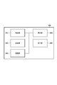
- FIG. 1 shows an exemplary configuration of a radiation imaging system 10 according to a first embodiment.
- 2 shows an exemplary hardware configuration of an image processing apparatus 100.
- FIG. 2 shows an exemplary configuration of a radiation detection apparatus 102.
- 5 is a timing chart showing processing timing by the radiation detection apparatus 102.
- 7 shows an example of a functional configuration of a substance information calculation unit 103.
- An example of the conversion table in Embodiment 1 is shown.
- An example of an image after pixel adjustment by the pixel adjustment unit 506 is shown. It shows a pattern with abnormal pixels and surrounding pixels. It shows a pattern with abnormal pixels and surrounding pixels.
- 7 shows another pattern of abnormal pixels and peripheral pixels. 7 shows another pattern of abnormal pixels and peripheral pixels. 7 shows another pattern of abnormal pixels and peripheral pixels. 7 shows another pattern of abnormal pixels and peripheral pixels.
- An example of the conversion table in the modification 1-3 is shown.
- An example of the conversion table in the modification 1-4 is shown.
- the structural example of the radiography system 1200 in Embodiment 2 is shown.
- 11 shows a functional configuration of the abnormal pixel detection unit 1201.
- An example of the determination result of an abnormal pixel is shown.
- An example of the conversion table in the modification 1-1 is shown.
- 11 shows a functional configuration of the abnormal pixel correction unit 1202.
- FIG. 1 shows an example of the configuration of a radiation imaging system 10 according to the first embodiment.
- the radiation imaging system 10 includes a radiation irradiation apparatus 101, a radiation detection apparatus 102, and an image processing apparatus 100.
- the radiation irradiating apparatus 101 irradiates a subject (not shown) with radiation.
- the radiation detection apparatus 102 acquires an image in which radiation of two different types of radiated energy has passed through the subject.
- the radiation detection apparatus 102 and the image processing apparatus 100 can also be configured as a radiation imaging apparatus as one apparatus.
- the image processing apparatus 100 includes a substance information calculation unit 103, a substance information correction unit 104, an operation control unit 105, and a display control unit 106 as a functional configuration.
- the substance information calculation unit 103 calculates substance information based on images obtained with two different types of energy, and detects whether or not there is an abnormal pixel as noise.
- the substance information in the present embodiment is the effective atomic number corresponding to the substance.
- the substance information correction unit 104 corrects the substance information calculated by the substance information calculation unit 103 based on the detection result of the abnormal pixel. The operations of the substance information calculation unit 103 and the substance information correction unit 104 will be described later.
- the operation control unit 105 converts the operation of the operator received by the operation unit 204 (FIG.
- the display control unit 106 controls the display unit 205 (FIG. 2) to display the information obtained by the substance information correction unit 104 according to the control by the operation control unit 105.
- FIG. 2 shows an example of the hardware configuration of the image processing apparatus 100.
- the image processing apparatus 100 includes a control unit 201, a storage unit 202, a communication unit 203, an operation unit 204, and a display unit 205 as a hardware configuration.
- the control unit 201 is, for example, a CPU (Central Processing Unit), and controls the operation of each component.
- the storage unit 202 is configured by a read only memory (ROM) or a random access memory (RAM).
- the storage unit 202 can store control instructions or programs.
- the storage unit 112 can also be used for temporary storage of a work memory or data when executing a program.
- the communication unit 203 performs control for communicating with an external device.
- the operation unit 204 receives an operation by the operator.
- the display unit 205 performs various displays.
- the display unit 205 includes, as an example, a display panel that displays image data.
- the display panel may be configured by a method such as LCD (Liquid Crystal Display), plasma, organic EL, or the like, or may be a projection display device that projects on a wall surface.
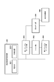
- the structural example of the radiation detection apparatus 102 is shown in FIG.
- the radiation detection apparatus 102 includes a radiation signal acquisition unit 301, a reset unit 302, a first sample hold unit 303, a second sample hold unit 304, a read unit 305, and a difference processing unit 306.
- the radiation signal acquisition unit 301 includes a phosphor 3011 and a light detector 3012.
- the radiation signal acquisition unit 301 converts radiation into a charge proportional to the amount and stores the charge. Specifically, the phosphor 3011 converts radiation into light, and the light detector 3012 detects the light converted by the phosphor 3011 and generates a charge corresponding to the light (converts light into charge) And accumulate.
- the reset unit 302 resets the charge accumulated in the radiation signal acquisition unit 301.
- the first sample hold unit 303 and the second sample hold unit 304 accumulate the charge of the radiation signal acquisition unit 301.
- the readout unit 305 reads out the charge accumulated in the first sample and hold unit 303 and the second sample and hold unit 304, and acquires it as a pixel value.
- the difference processing unit 306 performs difference processing on the pixel values read by the reading unit 305.
- FIG. 4 is a timing chart showing timings of radiation irradiation by the radiation irradiation apparatus 101 and detection operations by the radiation detection apparatus 102.
- a period 405 is a period from the reset to the acquisition timing of the first sample and hold
- a period 406 is a period from the reset to the acquisition timing of the second sample hole
- a period 407 is the image readout timing after the first sample and hold
- a period 408 indicates the image read timing after the second sample hold.
- the reset unit 302 resets the charge accumulated in the radiation signal acquisition unit 301.
- the radiation irradiation apparatus 101 emits radiation, and the radiation signal acquisition unit 301 converts the radiation into charge and accumulates the charge.
- the first sample and hold unit 303 reads the charge amount accumulated by the radiation signal acquisition unit 301.
- the reading unit 305 reads the image stored in the first sample and hold unit 303.
- the pixel value 410 proportional to the radiation dose irradiated in the period 405 is read.
- the second sample and hold unit 304 reads the charge amount accumulated by the radiation signal acquisition unit 301.
- the pixel value 411 proportional to the radiation dose irradiated in the period 406 is read.
- images of radiation of different energies can be acquired at high speed, and the influence of motion can be reduced even on a moving image such as fluoroscopy.
- An abnormal pixel is a pixel which arises when radiation which was not converted into light by fluorescent substance 3011 enters into photodetector 3012.
- FIG. 5 shows a functional configuration example of the substance information calculation unit 103.
- the substance information calculation unit 103 includes an image acquisition unit 501, an image correction unit 502, a pixel ratio calculation unit 503, a substance information conversion unit 504, an abnormal pixel detection unit 505, a pixel adjustment unit 506, and a substance information output unit 507.
- the image acquisition unit 501 acquires a plurality of radiation images from the radiation detection apparatus 102 by radiation imaging of a plurality of energy.
- the image acquisition unit 501 is a radiation image obtained by radiation imaging of two types of energy, a radiation image obtained by radiation imaging of higher energy (a radiation image of high energy), and a lower one.
- the image correction unit 502 corrects the two types of radiation images acquired by the image acquisition unit 501. The said correction can be performed based on the following (Formula 1).
- I correct is an image after correction
- I input is an image obtained by irradiating radiation when there is a subject
- I air is an image obtained under the same conditions as when I input is obtained without a separate subject
- I dark is an image acquired without irradiating radiation separately (all units are pixel values).
- the image correction unit 502 performs main correction on each of two types of radiation images. By performing such correction, it is possible to image the transmittance of the radiation irradiated to the subject.
- the pixel ratio calculation unit 503 calculates, for each pixel, pixel values of the high energy radiation image and the low energy radiation image. Specifically, the pixel ratio calculation unit 503 calculates a logarithmic ratio of pixel values of the two types of images after correction based on the following (Expression 2).
- I rate is a logarithmic ratio of the two types of images after correction
- I h is obtained at the higher energy of the two types of images
- I 1 are two types The image obtained by the lower energy among the images of and corrected by (Equation 1).
- the substance information conversion unit 504 converts the pixel ratio obtained by (Expression 2) into substance information that specifies a substance that may be included in the subject at the time of shooting.
- the effective atomic number corresponding to the substance is used as the substance information.
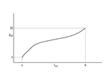
- a conversion table as shown in FIG. 6 is used for conversion to substance information.
- FIG. 6 shows an example of a conversion table from pixel ratio to effective atomic number in the present embodiment.
- the vertical axis is the effective atomic number
- the horizontal axis is the pixel ratio.
- the substance information conversion unit 504 calculates substance information by converting the pixel ratio into the effective atomic number.
- this conversion table can be prepared in advance by performing calculation based on the following (Equation 3).
- Equation 3 Z eff is the effective atomic number
- E h is the higher energy of the two types of energy (high energy)
- E 1 is the two lower types of energy (low energy)
- I rate (Z eff , E h , E l ) is a logarithmic ratio of the two types of images when the effective atomic number is Z eff , the high energy E h , and the low energy E l .
- ⁇ (E h , Z eff ) is a linear attenuation coefficient when a substance corresponding to Z eff is irradiated with high energy E h radiation
- ⁇ (E l , Z eff ) is a substance corresponding to Z eff. It is a linear attenuation coefficient when irradiated with radiation of energy El .
- the conversion table shown in FIG. 6 can be prepared in advance by performing the calculation of (Equation 3) for effective atomic numbers corresponding to various substances to be processed.
- effective atomic numbers 5 to 20 are used in FIG. 6 as effective atomic numbers corresponding to various target substances.
- This range is the effective atomic number corresponding to the substance that can be the subject in actual radiography. This range (value) may be set separately by the operator via the operation unit 204 or automatically according to the application.
- the number of combinations of high energy and low energy for the calculation of (Equation 3) may be determined in advance in accordance with the imaging conditions, the set value of the tube voltage, and the like. Also, in actual shooting, two types of images, high energy and low energy, often have a spectral distribution, but in (equation 3), calculation is performed by approximating high energy and low energy as a single energy Is going. Therefore, the radiation with high energy radiation and radiation with low energy radiation (such as water, aluminum, etc.) is photographed to calculate the transmittance, and the single energy with the closest transmittance is calculated. Calibration should be done to set.
- the abnormal pixel detection unit 505 determines whether the radiation not converted into light by the phosphor 3011 is incident on the light detector 3012. To detect That is, based on the pixel values of the plurality of radiation images acquired by the image acquisition unit 501, the abnormal pixel detection unit 505 determines whether an abnormal pixel exists in at least one radiation image of the plurality of radiation images. To detect. In the present embodiment, the abnormal pixel detection unit 505 determines the pixel value of the high energy radiation image, the pixel value of the low energy radiation image, and the information on the predetermined substance that may be included in the subject during radiation imaging.
- the abnormal pixel detection unit 505 has a line attenuation coefficient when the pixel ratio calculated by the pixel ratio calculation unit 503 irradiates a substance that may be included in the subject at the time of shooting with radiation of higher energy; When the substance is not included in the range of the ratio to the linear attenuation coefficient when the substance is irradiated with lower energy radiation, it is detected that an abnormal pixel is present.
- the abnormal pixel detection unit 505 determines whether or not the pixel ratio (logarithmic ratio) calculated using (Expression 2) is within the range of the conversion table shown in FIG. , Detects whether there is an abnormal pixel. That is, the abnormal pixel detection unit 505 determines whether the pixel ratio is within the range [a, b] of the horizontal axis (pixel ratio) in FIG.
- the range [a, b] of pixel ratios corresponding to effective atomic numbers 5 to 20 is a range expected to occur in actual shooting. Therefore, when the pixel ratio is out of the range [a, b], the abnormal pixel detection unit 505 detects that an abnormal pixel is present.
- the linear attenuation coefficient ratio becomes extremely small or large, and it is determined that abnormal pixels are present. Ru.
- the linear attenuation coefficient ratio is determined in accordance with the energy of radiation, it is abnormal even when the energy differs between sample and hold by referring to the range of the table according to the combination of the corresponding energy. It is possible to detect whether a pixel is present.
- the pixel adjustment unit 506 adjusts the pixel with respect to the abnormal pixel, and sets a value that can be identified as the abnormal pixel.
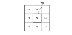
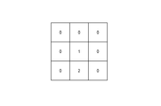
- FIG. 7 shows an example of an image in which 0 is set as a value with which the pixel adjustment unit 506 can identify an abnormal pixel.
- each pixel is given the effective atomic number converted using the conversion table of FIG.
- the pixel value of the abnormal pixel 701 is set to 0.
- the abnormal pixel 701 has a value different from the pixel value of the surrounding normal pixel, and can be identified as an abnormal pixel.
- the substance information output unit 507 outputs the substance information of which the pixel is adjusted by the pixel adjustment unit 506.
- the substance information correction unit 104 corrects the substance information in the abnormal pixel detected by the abnormal pixel detection unit 505 using the peripheral pixels of the pixel.
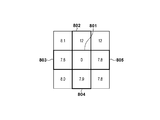
- FIGS. 8A and 8B show abnormal pixels and their surroundings when the substance information correction unit 104 corrects substance information in an abnormal pixel using substance information in a pixel adjacent to the abnormal pixel in the spatial direction. Shown are different patterns of pixels.
- FIG. 8A shows a pattern in which the vicinity of four abnormal pixels is a normal pixel.
- the substance information correction unit 104 corrects the abnormal pixel 801 using the pixels 802 to 803 in the vicinity of the surrounding four.
- the substance information correction unit 104 corrects the substance information of the abnormal pixel by interpolating the pixel value of the abnormal pixel 801 with the average value of the pixel values of the pixels 802 to 805.
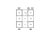
- FIG. 8B is a pattern in which any one of the four neighborhoods of the abnormal pixel is an abnormal pixel.
- the substance information correction unit 104 corrects the abnormal pixel 806 using the four peripheral pixels 807 to 810.
- the substance information correction unit 104 corrects the substance information of the abnormal pixel by interpolating the pixel value of the abnormal pixel 806 with the average value of the pixel values of the pixels 807 to 810.
- the method of changing the pixel used for correcting the abnormal pixel from the state of the abnormal pixel and its peripheral pixels is used, which pixel is used for correction
- the use is not limited to such a method.
- the pixel 801 may be corrected using only the pixels 802 to 804 without using the pixel 805. It is also possible to allow the operator to separately set the pixel used for correction via the operation unit 204 or automatically.
- the radiation imaging system 10 in the present embodiment it is possible to efficiently detect the presence or absence of an abnormal pixel from two image data having different energies and obtain substance information with reduced noise by correction. It becomes possible.
- the substance information calculation unit 103 uses the conversion table as shown in FIG. 6, but it is also possible to use a conversion table as shown in FIG. 15 instead of this.
- FIG. 15 is an example of the conversion table in the present modification.
- the pixel values of the low energy radiation image and the pixel values of the high energy radiation image are described in the first and second columns of the conversion table, and the effective atomic number is described in the third column.
- the values described in the conversion table can be calculated in advance based on (Equation 4) below.
- I correct is an image corresponding to the image after correction according to (Equation 1)
- E is energy of radiation
- ⁇ (E, Z eff ) is a radiation corresponding to each energy E and a material corresponding to effective atomic number Z eff Linear attenuation coefficient when irradiated
- t is the thickness of the material.
- the abnormal pixel detection unit 505 determines whether the combination of the pixel values of the two types of radiation images after correction by the image correction unit 502 is included in the range of the conversion table shown in FIG. It is detected whether an abnormal pixel exists. That is, the abnormal pixel detection unit 505 is a pixel for which each of the pixel values of the high energy radiation image and the low energy radiation image is obtained from the two types of energy and the effective atomic number of the substance that can be included in the subject at the time of imaging. If it is not included in the value range, it is detected that an abnormal pixel is present. In this modification, by using a conversion table as shown in FIG. 15, it becomes possible to calculate with high accuracy for radiation having a spectral distribution.
- the substance information correction unit 104 uses peripheral pixels in space to correct substance information, but it may use front and back frames on the time axis.
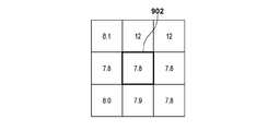
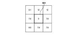
- 9A to 9C show three frames of the substance information when the substance information correction unit 104 corrects the substance information in the abnormal pixel using the substance information in the pixel adjacent to the abnormal pixel in the time direction. It is the figure which showed the value of substance information.
- FIG. 9A shows the m ⁇ 1th frame
- FIG. 9B shows the m th frame
- FIG. 9C shows the m + 1 th frame.
- the pixel 901 in the m-th frame is an abnormal pixel.
- the substance information correction unit 104 performs correction using frames before and after the frame in which an abnormal pixel appears in the time direction.
- the corrected value can be calculated by the following (Equation 5).
- Equation 5 Z eff _ m is the effective atomic number of the m th frame after correction
- Z eff _ m ⁇ 1 is the effective atomic number of the m ⁇ 1 th frame
- Z eff _ m + 1 is the effective atomic number of the m + 1 th frame.
- the substance information correction unit 104 can use the pixels 902 and 903 to calculate the corrected value of the abnormal pixel 901. By performing the correction using the front and rear frames in this manner, it is possible to perform the correction without losing the sharpness when the movement of the subject is small.
- the substance information correction unit 104 can also perform correction using only the front frame or only the rear frame.
- the substance information correction unit 104 can use not only one frame but a plurality of frames. For example, when performing correction using the previous three frames of the m-th frame, the effective atomic number of the m-3 th frame is multiplied by 0.1, the m-2 th frame is 0.4, and the m-1 th frame is multiplied by 0.5. It is also possible to calculate the effective atomic number of the m-th frame by adding.
- this example of correction shows an example of correction using only frames on the time axis, it is also possible to calculate correction pixels by combining values on the time axis and in space. It is also possible that the operator can separately set the correction method via the operation unit 204 or automatically.
- FIG. 10 is an example of the conversion table in the present modification.
- low energy pixel values and high energy pixel values are respectively described in the first and second columns of the conversion table, and thicknesses of bone tissue and soft tissue are respectively described in the third and fourth columns. ing.
- the values described in the conversion table can be calculated in advance by using the following (Equation 6).
- I correct is an image corresponding to the image after correction according to (Equation 1)
- E is energy of radiation
- ⁇ bone (E) is a linear attenuation coefficient when bone is irradiated with radiation of energy E
- t bone is bone Thickness
- ⁇ tissue (E) is a linear attenuation coefficient when the soft tissue is irradiated with energy E radiation
- t tissue is the thickness of the soft tissue.
- the conversion table may be set to a thickness that can be considered as bone. For example, when imaging the chest, it may be set to 0 to 40 mm for bones, 0 to 1200 mm for soft tissue and the like. Further, the setting value may be designated according to the physical constitution of the patient. For example, a method of using a measure, a method of estimating from a profile of pixel values, or the like may be used to measure the physique.
- the abnormal pixel detection unit 505 detects the thickness of the substance that can be included in the subject at the time of imaging and the two types of energy, each of the pixel values of the high energy radiation image and the low energy radiation image. When it is not included in the range of pixel values obtained from the above, it is detected that an abnormal pixel is present. In other words, in this modification, the abnormal pixel detection unit 505 determines that there is an abnormal pixel when the combination of the two types of images after correction by the image correction unit 502 is out of the conversion table shown in FIG. Then, it is possible to detect an abnormal pixel at the time of substance information calculation.
- the first embodiment shows a method of acquiring two types of energy using two sample and hold units, but it is possible to obtain more energy information by increasing the sample and hold.
- the image acquisition unit 501 may acquire a radiation image (a radiation image of high energy, a radiation image of medium energy, a radiation image of low energy) captured by three types of energy. It becomes possible.
- FIG. 11 is an example of the conversion table in the present modification.
- the pixel values of the low energy radiation image, the pixel values of the medium energy radiation image, and the pixel values of the high energy radiation image are described in the first to third columns of the conversion table, respectively.
- the sixth column describes the thicknesses of bone tissue, soft tissue, and contrast medium.
- the values described in the conversion table can be calculated in advance based on (Expression 7) below.
- I correct is an image corresponding to the image after correction according to (Equation 1)
- E energy of radiation
- ⁇ bone (E) is a linear attenuation coefficient when bone is irradiated with radiation of energy E
- t bone is bone Thickness
- ⁇ tissue (E) is the linear attenuation coefficient when soft tissue is irradiated with energy E radiation
- t tissue is the thickness of soft tissue
- ⁇ iodine (E) is irradiated contrast agent with energy E radiation
- the linear attenuation coefficient, where iodine is the thickness of the contrast agent.
- the contrast agent may create a table according to the size of the contrast target. For example, when a thin blood vessel such as the heart is to be imaged, the value may be set to a value such as 0-10 mm.
- the abnormal pixel detection unit 505 determines the thickness of a substance that can be included in the subject at the time of imaging and the three types of pixel values of the high energy radiation image, the medium energy radiation image, and the low energy radiation image. If it is not included in the range of pixel values obtained from the energy, it is detected that an abnormal pixel is present. In other words, in this modification, the abnormal pixel detection unit 505 determines that the combination of the three types of images after correction by the image correction unit 502 is an abnormal pixel when it is out of the conversion table shown in FIG. It is possible to detect an abnormal pixel at the time of substance information calculation.
- the various abnormal pixel detection methods described above can also be implemented in the image processing apparatus 100 in combination. Further, the process of the substance information conversion unit 504 and the process of the abnormal pixel detection unit 505 may be performed simultaneously, or the process of the abnormal pixel detection unit 505 may be performed first.
- FIG. 12 shows a configuration example of a radiation imaging system 1200 according to the second embodiment.
- the substance information is an effective atomic number, thickness information for each predetermined substance, and the like.
- the abnormal pixel detection unit 1201 detects the presence or absence of an abnormal pixel in each of two types of radiation images obtained by radiation imaging using radiation of two different types of energy.
- the abnormal pixel correction unit 1202 corrects the abnormal pixel detected by the abnormal pixel detection unit 1201.
- the substance information calculation unit 1203 calculates substance information on the basis of the image obtained by the type of energy. The operations of the abnormal pixel detection unit 1201, the abnormal pixel correction unit 1202, and the substance information calculation unit 1203 will be described later.
- FIG. 13 shows a functional configuration of the abnormal pixel detection unit 1201.
- the abnormal pixel detection unit 1201 includes an image acquisition unit 1301, an image correction unit 1302, a pixel ratio calculation unit 1303, an abnormal pixel determination unit 1304, and a determination result output unit 1305.
- the image acquisition unit 1301 acquires a high energy radiation image and a low energy radiation image from the radiation detection apparatus 102.
- the image correction unit 1302 corrects a high energy radiation image and a low energy radiation image.
- the correction method is the same as the processing performed by the image correction unit 502 of the first embodiment, and thus the description thereof is omitted.
- the pixel ratio calculation unit 1303 calculates pixel ratios of the high energy radiation image and the low energy radiation image.
- the calculation method is the same as that of the pixel ratio calculation unit 503 of the first embodiment, and thus the description thereof is omitted.
- the abnormal pixel determination unit 1304 determines, for each pixel, which of the high energy radiation image and the low energy radiation image has an abnormal pixel. Specifically, when the abnormal pixel determination unit 1304 irradiates a substance that may be included in the subject with radiation of higher energy and the material is irradiated with radiation of lower energy. Whether or not an abnormal pixel is present in the high energy radiation image or the low energy radiation image is determined by comparing the minimum value and the maximum value of the ratio with the linear attenuation coefficient of In this embodiment, unlike the first embodiment, it is not necessary to use a conversion table (such as FIG. 6) for converting substance information from pixel ratios, and only the minimum pixel ratio and the maximum pixel ratio in the conversion table are used.
- a conversion table such as FIG. 6
- the abnormal pixel determination unit 1304 can determine that there is an abnormal pixel when the ratio is larger than the maximum pixel ratio or smaller than the minimum pixel ratio. Further, since the abnormal pixel determination unit 1304 indicates that the pixel value of the low energy image is large when the pixel ratio is larger than the maximum pixel ratio, an abnormal pixel is present in the low energy radiation image. The abnormal pixel determination unit 1304 indicates that the pixel value of the high energy radiation image is large when the pixel ratio is smaller than the minimum pixel ratio, and thus the high energy radiation image It can be determined that an abnormal pixel exists in the direction of. Thus, by determining whether the pixel ratio is smaller or larger than the range, the result indicating which of the high energy radiation image and the low energy radiation image has an abnormal pixel is output. It is possible to
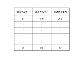
- the determination result output unit 1305 generates and outputs the determination result by the abnormal pixel determination unit 1304.
- FIG. 14 shows an example of the determination result generated by the determination result output unit 1305. Pixels with a pixel value of 0 are normal pixels, pixels with a pixel value of 1 are abnormal pixels in a high energy radiation image, and pixels with a pixel value of 2 are abnormal pixels in a low energy radiation image. Thus, as an example, the determination result output unit 1305 sets and outputs different numerical values for each pixel according to the detection result of the abnormal pixel. Such processing makes it possible to detect an abnormal pixel and to determine which of a high energy radiation image and a low energy radiation image has an abnormal pixel.
- FIG. 16 shows a functional configuration of the abnormal pixel correction unit 1202.
- the abnormal pixel correction unit 1202 includes an image acquisition unit 1601, a determination result acquisition unit 1602, a pixel value correction unit 1603, and an after-correction image output unit 1604.
- the abnormal pixel correction unit 1202 corrects the pixel values of the high energy radiation image and the low energy radiation image based on the determination result by the abnormal pixel determination unit 1304.
- the image acquisition unit 1601 acquires a high energy radiation image and a low energy radiation image.
- the determination result acquisition unit 1602 acquires the determination result from the determination result output unit 1305.
- the pixel value correction unit 1603 corrects the high energy radiation image and the low energy radiation image based on the acquired determination result.
- the corrected image output unit 1604 outputs the high energy radiation image and the low energy radiation image after correction. By performing such processing, it becomes possible to acquire substance information in which an abnormal pixel is corrected.
- the substance information calculation unit 1203 obtains the high energy radiation image and the low energy radiation image after the correction from the image output unit after correction 1604 and calculates the material information.
- the method of calculating the substance information is performed using the conversion table of FIG. 6 and the like, as in the first embodiment.
- the radiation imaging system 1200 in the present embodiment it is possible to obtain noise-reduced substance information by calculating substance information after detecting and correcting an abnormal pixel from two image data having different energies. It becomes.
- Example of change 2-1 a method of acquiring a radiation image by radiation imaging of two types of energy using two sample and hold units has been described, but it is possible to obtain more radiation images by increasing the sample and hold.
- the image acquisition unit 1301 can acquire three of a high energy radiation image, a medium energy radiation image, and a low energy radiation image.
- the pixel ratio calculation unit 1303 calculates, for each pixel, a ratio of at least two of pixel values of a high energy radiation image, a medium energy radiation image, and a low energy radiation image as two pixel ratios. Then, the abnormal pixel determination unit 1304 compares the two pixel ratios with the linear attenuation coefficient in the case of a substance that can be contained in the subject and the higher energy at the time of shooting and the linear attenuation coefficient in the case of the lower energy with the substance. It is determined whether abnormal pixels are present in the high energy radiation image, the medium energy radiation image, or the low energy radiation image by comparing the minimum value and the maximum value of the ratio of.
- the pixel ratio calculation unit 1303 calculates the pixel ratios of the high energy radiation image and the low energy radiation image, and the pixel ratios of the high energy radiation image and the medium energy radiation image. Then, the abnormal pixel determination unit 1304 determines whether or not the calculated minimum pixel ratio and the maximum pixel ratio are within the calculated pixel ratios. For example, when the abnormal pixel determination unit 1304 calculates a ratio using a high energy radiation image as a denominator for both pixel ratios, if the ratio is smaller than the minimum pixel ratio, the high energy radiation image includes an abnormal pixel and the maximum pixel If the ratio is larger, it is determined that there is an abnormal pixel in the medium energy radiation image or the low energy radiation image. It is possible to cope with an image of a plurality of two or more energies by calculating each ratio and detecting an abnormal pixel in this manner.
- Embodiments The present invention supplies a program that implements one or more functions of the above-described embodiments to a system or apparatus via a network or storage medium, and one or more processors in a computer of the system or apparatus read and execute the program. Can also be realized. It can also be implemented by a circuit (eg, an ASIC) that implements one or more functions.
- a circuit eg, an ASIC
Landscapes
- Health & Medical Sciences (AREA)
- Life Sciences & Earth Sciences (AREA)
- Engineering & Computer Science (AREA)
- Medical Informatics (AREA)
- Optics & Photonics (AREA)
- Biomedical Technology (AREA)
- Biophysics (AREA)
- High Energy & Nuclear Physics (AREA)
- Veterinary Medicine (AREA)
- Nuclear Medicine, Radiotherapy & Molecular Imaging (AREA)
- Public Health (AREA)
- Pathology (AREA)
- Radiology & Medical Imaging (AREA)
- Physics & Mathematics (AREA)
- Heart & Thoracic Surgery (AREA)
- Molecular Biology (AREA)
- Surgery (AREA)
- Animal Behavior & Ethology (AREA)
- General Health & Medical Sciences (AREA)
- Multimedia (AREA)
- Signal Processing (AREA)
- Apparatus For Radiation Diagnosis (AREA)
- Measurement Of Radiation (AREA)
Priority Applications (3)
| Application Number | Priority Date | Filing Date | Title |
|---|---|---|---|
| CN201880072088.4A CN111315297A (zh) | 2017-11-08 | 2018-09-12 | 图像处理装置、图像处理方法、放射线摄像装置、放射线摄像装置的控制方法和程序 |
| EP18875286.9A EP3708082A4 (en) | 2017-11-08 | 2018-09-12 | IMAGE PROCESSING DEVICE, IMAGE PROCESSING METHOD, RADIATION IMAGING DEVICE, AND METHOD AND PROGRAM FOR CONTROLLING THE RADIATION IMAGING DEVICE |
| US16/838,670 US20200236303A1 (en) | 2017-11-08 | 2020-04-02 | Radiation imaging system, image processing method, and non-transitory computer-readable storage medium |
Applications Claiming Priority (2)
| Application Number | Priority Date | Filing Date | Title |
|---|---|---|---|
| JP2017215898A JP2019084158A (ja) | 2017-11-08 | 2017-11-08 | 画像処理装置、画像処理方法、放射線撮影装置、放射線撮影装置の制御方法、およびプログラム |
| JP2017-215898 | 2017-11-08 |
Related Child Applications (1)
| Application Number | Title | Priority Date | Filing Date |
|---|---|---|---|
| US16/838,670 Continuation US20200236303A1 (en) | 2017-11-08 | 2020-04-02 | Radiation imaging system, image processing method, and non-transitory computer-readable storage medium |
Publications (1)
| Publication Number | Publication Date |
|---|---|
| WO2019092981A1 true WO2019092981A1 (ja) | 2019-05-16 |
Family
ID=66438777
Family Applications (1)
| Application Number | Title | Priority Date | Filing Date |
|---|---|---|---|
| PCT/JP2018/033731 Ceased WO2019092981A1 (ja) | 2017-11-08 | 2018-09-12 | 画像処理装置、画像処理方法、放射線撮影装置、放射線撮影装置の制御方法、およびプログラム |
Country Status (5)
| Country | Link |
|---|---|
| US (1) | US20200236303A1 (enExample) |
| EP (1) | EP3708082A4 (enExample) |
| JP (1) | JP2019084158A (enExample) |
| CN (1) | CN111315297A (enExample) |
| WO (1) | WO2019092981A1 (enExample) |
Families Citing this family (3)
| Publication number | Priority date | Publication date | Assignee | Title |
|---|---|---|---|---|
| JP7273470B2 (ja) | 2018-08-14 | 2023-05-15 | キヤノン株式会社 | 医用情報処理装置及び医用情報処理方法、プログラム |
| JP7370694B2 (ja) | 2018-08-14 | 2023-10-30 | キヤノン株式会社 | 医用情報処理装置及び医用情報処理方法、プログラム |
| JP7740950B2 (ja) * | 2021-10-06 | 2025-09-17 | キヤノンメディカルシステムズ株式会社 | X線画像処理装置、x線診断装置、方法及びプログラム |
Citations (3)
| Publication number | Priority date | Publication date | Assignee | Title |
|---|---|---|---|---|
| JPH11205682A (ja) * | 1998-01-13 | 1999-07-30 | Fuji Photo Film Co Ltd | エネルギーサブトラクション画像生成方法 |
| JP2012134781A (ja) * | 2010-12-22 | 2012-07-12 | Konica Minolta Medical & Graphic Inc | 欠陥画素マップ作成方法、欠陥画素マップ作成システム、コンソールおよび放射線画像撮影装置 |
| JP2014183475A (ja) | 2013-03-19 | 2014-09-29 | Canon Inc | 撮像システム |
Family Cites Families (6)
| Publication number | Priority date | Publication date | Assignee | Title |
|---|---|---|---|---|
| JP3363735B2 (ja) * | 1996-06-26 | 2003-01-08 | 松下電器産業株式会社 | X線画像装置 |
| JP2005152034A (ja) * | 2003-11-20 | 2005-06-16 | Canon Inc | 放射線撮像装置及び放射線撮像方法 |
| JP2009050394A (ja) * | 2007-08-24 | 2009-03-12 | Fujifilm Corp | 画像処理装置、方法及びプログラム |
| US8218837B2 (en) * | 2008-06-06 | 2012-07-10 | General Electric Company | Material composition detection from effective atomic number computation |
| JP5457118B2 (ja) * | 2009-09-18 | 2014-04-02 | 浜松ホトニクス株式会社 | 放射線検出装置 |
| JP6242631B2 (ja) * | 2012-08-30 | 2017-12-06 | 東芝メディカルシステムズ株式会社 | 医用画像処理装置及びx線コンピュータ断層撮影装置 |
-
2017
- 2017-11-08 JP JP2017215898A patent/JP2019084158A/ja active Pending
-
2018
- 2018-09-12 WO PCT/JP2018/033731 patent/WO2019092981A1/ja not_active Ceased
- 2018-09-12 EP EP18875286.9A patent/EP3708082A4/en not_active Withdrawn
- 2018-09-12 CN CN201880072088.4A patent/CN111315297A/zh active Pending
-
2020
- 2020-04-02 US US16/838,670 patent/US20200236303A1/en not_active Abandoned
Patent Citations (3)
| Publication number | Priority date | Publication date | Assignee | Title |
|---|---|---|---|---|
| JPH11205682A (ja) * | 1998-01-13 | 1999-07-30 | Fuji Photo Film Co Ltd | エネルギーサブトラクション画像生成方法 |
| JP2012134781A (ja) * | 2010-12-22 | 2012-07-12 | Konica Minolta Medical & Graphic Inc | 欠陥画素マップ作成方法、欠陥画素マップ作成システム、コンソールおよび放射線画像撮影装置 |
| JP2014183475A (ja) | 2013-03-19 | 2014-09-29 | Canon Inc | 撮像システム |
Non-Patent Citations (1)
| Title |
|---|
| See also references of EP3708082A4 |
Also Published As
| Publication number | Publication date |
|---|---|
| EP3708082A4 (en) | 2021-06-09 |
| CN111315297A (zh) | 2020-06-19 |
| US20200236303A1 (en) | 2020-07-23 |
| JP2019084158A (ja) | 2019-06-06 |
| EP3708082A1 (en) | 2020-09-16 |
Similar Documents
| Publication | Publication Date | Title |
|---|---|---|
| JP5384521B2 (ja) | 放射線撮像装置 | |
| JP5405093B2 (ja) | 画像処理装置及び画像処理方法 | |
| KR101961351B1 (ko) | 방사선 촬영 시스템 및 방사선 촬영 방법 | |
| CN105982683B (zh) | 一种同时消除射线硬化影响的x射线探测器综合校正方法 | |
| KR101850871B1 (ko) | 방사선 영상의 처리방법 및 방사선 촬영시스템 | |
| EP2702449B1 (en) | System and method for correction of geometric distortion of multi-camera flat panel x-ray detectors | |
| JP6156847B2 (ja) | 放射線画像処理装置および方法並びにプログラム | |
| WO2019026409A1 (ja) | 放射線撮像装置および放射線撮像システム | |
| JP2018033578A (ja) | 放射線撮影装置、放射線撮影システム、放射線撮影方法、及びプログラム | |
| EP1903499A2 (en) | Radiological image capturing system and radiological image capturing method | |
| WO2019092981A1 (ja) | 画像処理装置、画像処理方法、放射線撮影装置、放射線撮影装置の制御方法、およびプログラム | |
| US8160202B2 (en) | Radiographic apparatus | |
| JP4584550B2 (ja) | X線計測装置 | |
| US20180249977A1 (en) | An X-ray System With Computer Implemented Methods For Image Processing | |
| JP2003052687A (ja) | X線検査装置 | |
| JP2009171990A (ja) | X線検出器を較正するシステム及び方法 | |
| JP2019084158A5 (enExample) | ||
| US7949174B2 (en) | System and method for calibrating an X-ray detector | |
| CN101291625A (zh) | 放射线摄像装置以及放射线检测信号处理方法 | |
| JP5062312B2 (ja) | X線透視装置 | |
| JP5386284B2 (ja) | 放射線撮像装置 | |
| JP7115545B2 (ja) | 医用x線画像処理装置およびx線画像撮影装置 | |
| JP2008237836A (ja) | 放射線撮像装置及び方法 | |
| CN110755098A (zh) | 平板探测器的增益函数的确定方法、图像校正方法和装置 | |
| US20100061654A1 (en) | Scatter estimation and reduction method and apparatus |
Legal Events
| Date | Code | Title | Description |
|---|---|---|---|
| 121 | Ep: the epo has been informed by wipo that ep was designated in this application |
Ref document number: 18875286 Country of ref document: EP Kind code of ref document: A1 |
|
| NENP | Non-entry into the national phase |
Ref country code: DE |
|
| ENP | Entry into the national phase |
Ref document number: 2018875286 Country of ref document: EP Effective date: 20200608 |