WO2019087823A1 - 電気治療器、制御方法、および治療システム - Google Patents
電気治療器、制御方法、および治療システム Download PDFInfo
- Publication number
- WO2019087823A1 WO2019087823A1 PCT/JP2018/039032 JP2018039032W WO2019087823A1 WO 2019087823 A1 WO2019087823 A1 WO 2019087823A1 JP 2018039032 W JP2018039032 W JP 2018039032W WO 2019087823 A1 WO2019087823 A1 WO 2019087823A1
- Authority
- WO
- WIPO (PCT)
- Prior art keywords
- treatment
- frequency
- user
- pulse voltage
- stimulation intensity
- Prior art date
- Legal status (The legal status is an assumption and is not a legal conclusion. Google has not performed a legal analysis and makes no representation as to the accuracy of the status listed.)
- Ceased
Links
Images


Classifications
-
- A—HUMAN NECESSITIES
- A61—MEDICAL OR VETERINARY SCIENCE; HYGIENE
- A61N—ELECTROTHERAPY; MAGNETOTHERAPY; RADIATION THERAPY; ULTRASOUND THERAPY
- A61N1/00—Electrotherapy; Circuits therefor
- A61N1/18—Applying electric currents by contact electrodes
- A61N1/32—Applying electric currents by contact electrodes alternating or intermittent currents
- A61N1/36—Applying electric currents by contact electrodes alternating or intermittent currents for stimulation
- A61N1/36014—External stimulators, e.g. with patch electrodes
- A61N1/3603—Control systems
- A61N1/36034—Control systems specified by the stimulation parameters
-
- A—HUMAN NECESSITIES
- A61—MEDICAL OR VETERINARY SCIENCE; HYGIENE
- A61N—ELECTROTHERAPY; MAGNETOTHERAPY; RADIATION THERAPY; ULTRASOUND THERAPY
- A61N1/00—Electrotherapy; Circuits therefor
- A61N1/02—Details
- A61N1/04—Electrodes
- A61N1/0404—Electrodes for external use
- A61N1/0408—Use-related aspects
- A61N1/0452—Specially adapted for transcutaneous muscle stimulation [TMS]
-
- A—HUMAN NECESSITIES
- A61—MEDICAL OR VETERINARY SCIENCE; HYGIENE
- A61N—ELECTROTHERAPY; MAGNETOTHERAPY; RADIATION THERAPY; ULTRASOUND THERAPY
- A61N1/00—Electrotherapy; Circuits therefor
- A61N1/02—Details
- A61N1/04—Electrodes
- A61N1/0404—Electrodes for external use
- A61N1/0472—Structure-related aspects
- A61N1/0492—Patch electrodes
-
- A—HUMAN NECESSITIES
- A61—MEDICAL OR VETERINARY SCIENCE; HYGIENE
- A61N—ELECTROTHERAPY; MAGNETOTHERAPY; RADIATION THERAPY; ULTRASOUND THERAPY
- A61N1/00—Electrotherapy; Circuits therefor
- A61N1/18—Applying electric currents by contact electrodes
- A61N1/32—Applying electric currents by contact electrodes alternating or intermittent currents
- A61N1/36—Applying electric currents by contact electrodes alternating or intermittent currents for stimulation
- A61N1/36003—Applying electric currents by contact electrodes alternating or intermittent currents for stimulation of motor muscles, e.g. for walking assistance
-
- A—HUMAN NECESSITIES
- A61—MEDICAL OR VETERINARY SCIENCE; HYGIENE
- A61N—ELECTROTHERAPY; MAGNETOTHERAPY; RADIATION THERAPY; ULTRASOUND THERAPY
- A61N1/00—Electrotherapy; Circuits therefor
- A61N1/18—Applying electric currents by contact electrodes
- A61N1/32—Applying electric currents by contact electrodes alternating or intermittent currents
- A61N1/36—Applying electric currents by contact electrodes alternating or intermittent currents for stimulation
- A61N1/36014—External stimulators, e.g. with patch electrodes
- A61N1/36021—External stimulators, e.g. with patch electrodes for treatment of pain
Definitions
- the present disclosure relates to an electrotherapeutic device, a control method, and a treatment system.
- an electric treatment device for relieving coli and pain is known.
- Such an electrotherapeutic device brings an electrode into contact with the surface of the body such as the abdomen or the back and provides stimulation by outputting an electrical signal to the muscle through the electrode.
- Patent Document 1 discloses an electrical stimulation device.
- the electrical stimulation apparatus detects the output of each output unit while performing stimulation by changing the frequency and waveform of the stimulation signal, and controls the output to be a predetermined value at all times.
- the electrical stimulation apparatus which concerns on patent document 1 changes the frequency of a stimulation signal, and performs stimulation. As described above, when the electrical stimulation is performed while changing the frequency in the predetermined frequency range, the electrical stimulation felt by the user is changed. Therefore, when electrical stimulation is performed at a specific frequency within a predetermined frequency range, the user may be uncomfortable due to the user's unintended electrical stimulation (for example, the stimulation is too strong). There is sex. Patent Document 1 does not teach or suggest at all a technique for solving the problem.
- An object in one aspect of the present disclosure is to provide an electrotherapy device, a control method, and a treatment system capable of providing a comfortable treatment for the user even when the frequency of the pulse voltage supplied to the user changes during treatment. It is.
- a treatment content setting unit configured to set treatment content designated by a user, and pulse voltages applied to a plurality of electrodes in contact with the user's body region control the treatment content according to the treatment content.
- a treatment execution unit for performing treatment and an output control unit for outputting a pulse voltage of a first frequency included in a predetermined frequency range before the treatment of the site is performed by the treatment execution unit.
- the treatment content setting unit receives an input of the electrical stimulation intensity desired by the user.
- the treatment execution unit performs treatment of the site by changing the pulse voltage corresponding to the electric stimulation intensity desired by the user in a predetermined frequency range.
- the output control unit gradually increases the electric stimulation intensity and outputs a pulse voltage corresponding to the electric stimulation intensity at the first frequency.
- the first frequency is a maximum frequency in a predetermined frequency range, or a frequency within a range of 20 Hz to 60 Hz.
- the treatment can be performed without giving discomfort to the user due to too strong electrical stimulation during treatment, or giving discomfort due to the occurrence of muscle contraction during treatment to the user.
- the treatment content setting unit receives an input of the first electric stimulation intensity desired by the user.
- the output control unit outputs a pulse voltage corresponding to the first electrical stimulation intensity at a second frequency included in the frequency range.
- the treatment execution unit generates the first electrical stimulation intensity The treatment of the site is carried out by changing the corresponding pulse voltage in the frequency range.
- the first frequency is a maximum frequency in a predetermined frequency range.
- the second frequency is a frequency within the range of 20 Hz to 60 Hz.
- the treatment can be performed without giving discomfort to the user during the treatment due to the occurrence of muscle contraction, without giving discomfort to the user during treatment.
- the treatment execution unit sweeps in the direction of the frequency increasing from the minimum frequency to the maximum frequency in the frequency range and sweeps in the direction of the frequency decreasing from the maximum frequency to the minimum frequency. Changes the frequency of the pulse voltage.
- the electrotherapy device is a low frequency therapy device. According to the above configuration, the user can receive treatment in a more appropriate frequency range.
- a method of controlling an electrotherapy device includes: setting a treatment content specified by a user; and controlling a pulse voltage applied to a plurality of electrodes in contact with a region of the user's body And performing the treatment of the site according to the treatment content, and outputting the pulse voltage of the first frequency included in the predetermined frequency range before the treatment of the site is performed.
- the setting step includes receiving an input of the user's desired electrical stimulation intensity.
- the step of performing includes performing treatment of the site by changing a pulse voltage corresponding to the user's desired electrical stimulation intensity in a predetermined frequency range.
- a treatment system in another example of the present disclosure, includes a terminal device and an electrotherapy device configured to wirelessly communicate with the terminal device.
- the electrotherapy device treats the site according to the treatment content by controlling the treatment content setting unit that sets the treatment content specified by the user and the pulse voltage applied to the plurality of electrodes in contact with the user's body region.
- an output control unit for outputting a pulse voltage of a first frequency included in a predetermined frequency range before the treatment of the site is performed by the treatment execution unit.
- the treatment content setting unit receives an input of the electrical stimulation intensity desired by the user via the terminal device.
- the treatment execution unit performs treatment of the site by changing the pulse voltage corresponding to the electric stimulation intensity desired by the user in a predetermined frequency range.
- FIG. 7 is a view showing an example of the appearance of the electrotherapy device according to the first embodiment.
- FIG. 5 is a block diagram showing an example of a hardware configuration of the electrotherapy device according to the first embodiment. It is a figure for demonstrating the parameter of a pulse voltage waveform.
- FIG. 5 is a block diagram showing an example of a functional configuration of the electrotherapy device according to the first embodiment.
- 7 is a flowchart showing an example of a processing procedure of the electric therapeutic device according to the first embodiment. It is a flowchart which shows an example of the processing procedure of the electric therapeutic device according to the modification of Embodiment 1.
- FIG. 10 is a diagram showing a schematic configuration of a treatment system according to a second embodiment.
- FIG. 16 is a perspective view showing an example of a configuration of an electric therapeutic device according to a second embodiment. It is a perspective view which shows the state which isolate
- FIG. 16 is a block diagram showing an example of a hardware configuration of a terminal according to a second embodiment.
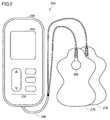
- FIG. 1 is a diagram showing an electrotherapy device 200 according to the present embodiment.
- the electrotherapy device 200 includes a control device 205 which is a main body, and a pair of pads 270 for attaching to a treatment site (for example, a knee).
- the control device 205 and the pad 270 are electrically connected by a cord.
- the supporter 40 is a knee supporter covering the entire knee of the user.
- the electrotherapy device 200 is, for example, a low frequency treatment device that relieves the user's knee pain and performs treatment such as loosening of the shoulder by supplying low frequency pulse current.
- the frequency of the low frequency pulse current is, for example, 1 Hz to 1200 Hz.
- the pad 270 has a sheet-like shape and is attached to the body of the user. On one surface (surface not in contact with the body) of the pad 270, a plug corresponding to an electrode (not shown) formed on the other surface (surface in contact with the body) is provided.
- the electrode is formed of, for example, a conductive gel-like material or the like.
- Control device 205 mainly includes a treatment content setting unit 302, an output control unit 304, and a treatment execution unit 306.
- the treatment content setting unit 302 receives various instructions on the treatment content from the user, and gives instructions to the output control unit 304 and the treatment execution unit 306.
- the treatment execution unit 306 treats the knee by controlling a pulse voltage applied to the electrodes of the pair of pads 270 in contact with a part of the user's body (here, the knee) in accordance with a treatment instruction from the user.
- the treatment execution unit 306 outputs a pulse voltage whose frequency is changed continuously or stepwise repeatedly in a predetermined frequency range K (for example, 1 Hz to 250 Hz).
- the voltage waveform D1 of the pulse voltage output by the treatment execution unit 306 is a sweep waveform that continuously increases from 1 Hz to 250 Hz and decreases continuously from 250 Hz to 1 Hz.
- the predetermined frequency range K (1 Hz to 250 Hz) is a frequency set in advance in the electrotherapy device 200 as a frequency range in the case where treatment using a sweep waveform whose frequency changes repeatedly is performed in the electrotherapy device 200. It is a range.
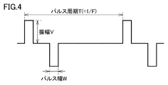
- the amplitude and pulse width of the pulse voltage and the like are appropriately changed in accordance with the selection instruction of the treatment mode and the adjustment instruction of the electric stimulation intensity.
- the display of the control device 205 or the like is used to prompt the user to adjust the electrical stimulation intensity.
- the user gives the electrotherapy device 200 an adjustment instruction of the electric stimulation intensity.
- the output control unit 304 outputs a pulse voltage according to the adjustment instruction of the electrical stimulation intensity at the frequency Fs included in the frequency range K before the treatment of the knee is started by the pulse voltage output from the treatment execution unit 306.
- the frequency Fs is set to a frequency at which the user feels that the electrical stimulation is strongest in the frequency range K.
- the frequency range K is 1 Hz to 250 Hz
- the frequency Fs is set to 250 Hz which is the maximum frequency.
- the voltage waveform D2 of the pulse voltage output by the output control unit 304 is a 250 Hz pulse waveform.
- the treatment content setting unit 302 receives an input of desired electric stimulation intensity from the user, and the received electric stimulation intensity is used as the electric stimulation intensity at the time of treatment.
- the treatment execution unit 306 performs the treatment of the knee by changing the pulse voltage corresponding to the set electrical stimulation intensity in the frequency range K.
- the user can adjust the electrical stimulation intensity to a desired intensity at the frequency at which the user can most easily feel the electrical stimulation before receiving a full-scale treatment by the sweep waveform whose frequency changes repeatedly. Therefore, it is possible to prevent the user from feeling uncomfortable or surprised by the fact that the electrical stimulation is too strong after the treatment starts.
- the frequency range in which muscles are likely to contract is 20 Hz to 60 Hz.
- the frequency Fs described above may be set to a frequency within the range of 20 Hz to 60 Hz.
- the electrical stimulation intensity can be adjusted to a desired intensity at a frequency at which the muscle tends to contract in the frequency range K. Therefore, it is possible to prevent the user from feeling uncomfortable or surprised by the occurrence of muscle contraction after the treatment starts.
- the electrotherapy device 200 even when the frequency of the pulse voltage given to the user at the time of treatment changes, it is possible to perform a comfortable treatment for the user.
- FIG. 2 is a view showing an example of the appearance of the electrotherapy device 200 according to the first embodiment.
- the electrotherapy device 200 includes a control device 205, a pair of pads 270, and a cord 280 for electrically connecting the control device 205 and the pads 270.
- the control device 205 and the pad 270 are connected by connecting the plug 282 of the cord 280 and the plug on the pad 270 side and inserting the cord 280 into the jack of the control device 205.
- the polarity of the electrode formed on one pad 270 is positive, the polarity of the electrode formed on the other pad 270 is negative.
- the control device 205 is provided with an input interface 230 composed of various buttons and a display 260.
- the input interface 230 includes a power button for switching on / off the power, a mode selection button for selecting a treatment mode, a treatment start button, an adjustment button for adjusting the electric stimulation intensity, and the like.
- the input interface 230 is not limited to the above configuration, and may be any configuration that can realize various operations by the user described later.
- the input interface 230 may be configured by, for example, other buttons, dials, switches, and the like.
- the display 260 displays the intensity of electrical stimulation, the remaining time of treatment, the treatment mode, the wearing condition of the pad 270, etc., and various messages.
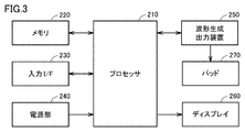
- FIG. 3 is a block diagram showing an example of a hardware configuration of the electrotherapy device 200 according to the first embodiment.
- the electrotherapy device 200 includes a processor 210, a memory 220, an input interface 230, a power supply unit 240, a waveform generation output device 250, and a display 260.
- the processor 210 is typically an arithmetic processing unit such as a central processing unit (CPU) or a multi processing unit (MPU).
- the processor 210 reads out and executes a program stored in the memory 220 to function as a control unit that controls the operation of each unit of the electrotherapy device 200.
- the processor 210 implements each of the processing (steps) of the electrotherapy device 200 described later by executing the program.
- the memory 220 is realized by a random access memory (RAM), a read-only memory (ROM), a flash memory, or the like.
- the memory 220 stores programs executed by the processor 210, data used by the processor 210, and the like.
- the input interface 230 receives an operation input to the electrotherapy device 200, and includes various buttons as described above. When the user operates the various buttons, a signal of the operation is input to the processor 210.
- the power supply unit 240 supplies power to each component of the electrotherapy device 200.
- a power source for example, an alkaline dry battery or a secondary battery such as a lithium ion battery or a nickel hydrogen battery is used, and the battery voltage is stabilized to generate a drive voltage to be supplied to each component.
- the waveform generation output device 250 outputs a current (hereinafter also referred to as “treatment current”) flowing to the treatment site on the user's body through the pad 270.
- treatment current a current flowing to the treatment site on the user's body through the pad 270.
- the waveform generation and output device 250 includes a booster circuit, a voltage adjustment circuit, an output circuit, a current detection circuit, and the like.
- the booster circuit boosts the power supply voltage to a predetermined voltage.
- the voltage adjustment circuit adjusts the voltage boosted by the booster circuit to a voltage corresponding to the electric stimulation intensity set by the user.
- adjustment of the electrical stimulation can be set at a predetermined number of levels (for example, 10 levels) by the adjustment button.
- the processor 210 receives the setting input of the electrical stimulation intensity via the adjustment button, and instructs the waveform generation and output device 250 (voltage adjustment circuit) to adjust to a voltage corresponding to the received electrical stimulation intensity.
- the output circuit generates a treatment waveform (pulse waveform) according to the treatment mode based on the voltage adjusted by the voltage adjustment circuit, and outputs the treatment waveform to (the electrode of) the pad 270 via the code 280.
- a control signal corresponding to the operation content is input from the processor 210 to the output circuit.
- Ru The output circuit outputs a treatment waveform according to the control signal.
- the electrotherapy device 200 a plurality of treatment modes are prepared in advance.
- the treatment mode "Momi”, “Tataki”, “Press”, “Sweep” mode and the like can be mentioned.
- the output circuit corresponds to various modes such as “Momi”, “Tataki”, “Push”, and “Sweep” by changing the pulse waveform (including pulse width, pulse interval, frequency, and output polarity). It can generate electrical stimulation. Also, the output circuit adjusts the intensity of the electrical stimulation by changing the amplitude of the pulse voltage. The output circuit may be configured to adjust the electrical stimulation intensity by changing the pulse width. A known waveform can be used as a specific pulse voltage waveform.
- FIG. 4 is a diagram for explaining parameters of a pulse voltage waveform.
- the processor 210 can change the treatment content for the user by changing at least one of these three parameters.
- the current detection circuit detects the value of the current flowing between the pair of pads 270, and inputs a signal indicating the detected value to the processor 210.
- the processor 210 uses the current value input from the current detection circuit to determine whether the pad 270 is attached (pasted) to the user or the pad 270 is not attached to the user (peeled off) ) Can detect the state.
- the processor 210 determines that the plurality of electrodes are in contact (that is, the pair of pads 270 is attached to the user), and the current If the value is less than the predetermined value, it is determined that at least one of the plurality of electrodes is not in contact (that is, at least one of the pair of pads 270 is not worn by the user). This is because, if at least one of the pair of pads 270 is not properly worn by the user, a current loop is not established, which is output from one of the pads 270, passes through the human body, and returns to the other pad 270. It uses the principle that no more current flows.
- the display 260 is configured by, for example, an LCD (Liquid Crystal Display), and displays various information according to an instruction from the processor 210.
- LCD Liquid Crystal Display
- FIG. 5 is a block diagram showing an example of a functional configuration of the electrotherapy device 200 according to the first embodiment.
- the electrotherapy device 200 includes a treatment content setting unit 302, an output control unit 304, a treatment execution unit 306, and a display control unit 308.
- the treatment content setting unit 302 sets the treatment content specified by the user. Specifically, the treatment content setting unit 302 receives the setting input of the treatment content via the input interface 230.
- the treatment content includes the treatment mode and the electrical stimulation intensity.
- the treatment content setting unit 302 may receive, from the user, a setting input of a treatment time which is a time for performing treatment according to the treatment content. However, the treatment time may be a preset fixed time.
- the treatment content setting unit 302 determines that the treatment mode designated by the user is a mode in which treatment is performed using a pulse voltage whose frequency changes in the frequency range K (that is, a mode using a sweep waveform), electricity is output. Execute processing to adjust the stimulation intensity.
- the treatment content setting unit 302 instructs the display control unit 308 to display a selection screen of the adjustment pattern of the electric stimulation intensity.
- the display control unit 308 causes the display 260 to display an adjustment pattern selection screen.
- the selection screen has a pattern Pa for adjusting the electric stimulation intensity by outputting a pulse voltage of the maximum frequency in the frequency range K, or a pattern Pb for adjusting the electric stimulation intensity by outputting a pulse voltage of 20 Hz to 60 Hz.
- Is a screen that allows the user to select For example, the user selects the pattern Pa when it is easy to feel discomfort with respect to too strong electrical stimulation, and selects the pattern Pb when it is easy to feel discomfort with the occurrence of muscle contraction.
- the treatment content setting unit 302 When the treatment content setting unit 302 receives a selection instruction of the pattern Pa via the input interface 230, the treatment content setting unit 302 instructs the output control unit 304 to output a pulse voltage at the maximum frequency. When the treatment content setting unit 302 receives an instruction to select the pattern Pb, the treatment content setting unit 302 instructs the output control unit 304 to output a pulse voltage at a frequency included in 20 Hz to 60 Hz.
- the output control unit 304 applies a pulse voltage for adjusting the electrical stimulation intensity to the pad 270. Specifically, the output control unit 304 outputs a pulse voltage at a frequency Fs (that is, the maximum frequency or a frequency included in 20 Hz to 60 Hz) according to the instruction of the treatment content setting unit 302.
- Fs that is, the maximum frequency or a frequency included in 20 Hz to 60 Hz
- the output control unit 304 gradually increases the electric stimulation intensity, and outputs a pulse voltage corresponding to the electric stimulation intensity at the frequency Fs.
- the initial value of the electrical stimulation intensity is set to, for example, the lowest level (for example, level 1) of a predetermined number of levels (for example, 10 levels).
- the output control unit 304 raises the level by one each time a predetermined time elapses, and gradually increases the electric stimulation intensity.
- the treatment content setting unit 302 may receive an instruction input of the electrical stimulation intensity from the user via the input interface 230. In this case, the output control unit 304 outputs a pulse voltage corresponding to the electric stimulation intensity according to the instruction input at the frequency Fs.
- the treatment content setting unit 302 receives an input of the user's desired electrical stimulation intensity. For example, when receiving the input of the level “6” of the desired electric stimulation intensity, the treatment content setting unit 302 sets the level of the electric stimulation intensity in the treatment mode using the sweep waveform to “6”.
- the treatment execution unit 306 applies a pulse voltage for treatment to the pad 270. Specifically, the treatment execution unit 306 performs treatment of the treatment site by changing the pulse voltage corresponding to the user's desired electric stimulation intensity (for example, level “6”) in the frequency range K.
- treatment executive 306 sweeps in the direction of frequencies increasing from the lowest frequency (e.g., 1 Hz) to the highest frequency (e.g., 250 Hz) in frequency range K and from the highest frequency to the lowest frequency. By sweeping in the direction of decreasing frequency, the frequency of the pulse voltage is changed. Note that the treatment execution unit 306 may arbitrarily change the frequency according to the treatment mode as long as the frequency range K is satisfied.
- FIG. 6 is a flow chart showing an example of the processing procedure of the electrotherapy device 200 according to the first embodiment. Each step in FIG. 6 is mainly executed by the processor 210 of the electrotherapy device 200.
- the electrotherapy device 200 receives a setting input of treatment content via the input interface 230 (step S10). Specifically, the electrotherapy device 200 receives setting input of the treatment mode and the electric stimulation intensity.
- the electrotherapy device 200 determines whether the received treatment mode is a treatment mode in which the frequency is changed in the frequency range K (i.e., using a sweep waveform) (step S12). If the received treatment mode is not a treatment mode using a sweep waveform (NO in step S12), the electrotherapy device 200 starts treatment (step S14). Specifically, the electrotherapy device 200 outputs a pulse voltage according to the treatment content received in the treatment step S10. Subsequently, the process of step S28 described later is performed.
- the electrotherapy device 200 displays an adjustment screen of the electric stimulation intensity on the display 260 (step S16).
- the adjustment screen is a screen that allows the user to select which of the above-described pattern Pa and pattern Pb the electric stimulation intensity is to be adjusted.
- the electrotherapy device 200 determines whether to adjust the electrical stimulation intensity with the pattern Pa (step S18). Specifically, when the adjustment screen is displayed, the electrotherapy device 200 determines whether the selection of the pattern Pa has been received via the input interface 230.
- the electric therapy device 200 When the electric therapy device 200 receives the selection of the pattern Pa (that is, adjusts the electric stimulation intensity by the pattern Pa) (YES in step S18), it outputs the pulse voltage of the maximum frequency in the frequency range K (step S20). Typically, the electrotherapy device 200 fixes the pulse frequency to the maximum frequency and gradually increases the electric stimulation intensity (for example, the amplitude of the pulse voltage).
- the electrotherapy device 200 determines whether the input of the desired electrical stimulation intensity has been received via the input interface 230 (step S22). If the input has not been received (NO in step S22), the electrotherapy device 200 executes the process of step S20. When the input is received (YES in step S22), the electrotherapy device 200 sets the received electric stimulation intensity as the electric stimulation intensity at the time of the treatment execution (step S24).
- the electrotherapy device 200 starts the treatment of the treatment site of the user (step S26). Specifically, the electrotherapy device 200 performs treatment of the treatment site by changing the pulse voltage corresponding to the set electric stimulation intensity in the frequency range K. The electrotherapy device 200 may start the treatment when receiving the treatment start instruction via the input interface 230.
- the electrotherapy device 200 determines whether a setting change input for changing the setting of the treatment content is received from the user via the input interface 230 (step S28). If the setting change input has been received (YES in step S28), the electrotherapy device 200 returns to step S12. That is, the electrotherapy device 200 determines whether the treatment mode included in the changed treatment content is a treatment mode using a sweep waveform.
- step S30 determines whether the treatment time has elapsed. If the treatment time has not elapsed (NO in step S30), the electrotherapy device 200 returns to step S28. That is, the electrotherapy device 200 continues the treatment. If the treatment time has elapsed (YES in step S30), the electrotherapy device 200 ends the process.
- the electrotherapy device 200 does not receive selection of the pattern Pa (that is, when the electric stimulation intensity is not adjusted by the pattern Pa) (NO in step S18), the electricity is applied by the pattern Pb. It is determined whether the stimulation intensity is to be adjusted (step S32).
- the electric therapy device 200 When the electric therapy device 200 receives the selection of the pattern Pb (that is, adjusts the electric stimulation intensity with the pattern Pb) (YES in step S32), the frequency in the range of 20 Hz to 60 Hz (here, 60 Hz) Output) (step S34).
- the electrotherapy device 200 fixes the pulse frequency to 60 Hz and gradually increases the electric stimulation intensity.
- the electrotherapy device 200 may gradually increase the electric stimulation intensity while repeatedly changing the frequency in the range of 20 Hz to 60 Hz.
- the electrotherapy device 200 repeats the pulse voltage corresponding to the electrical stimulation intensity A1 (for example, level 1) continuously or stepwise in the frequency range of 20 Hz to 60 Hz. Output while changing. Subsequently, the electrotherapy device 200 (the output control unit 304) corresponds to the increased electrical stimulation intensity A2 (for example, level 2) when a predetermined time elapses after the pulse voltage corresponding to the electrical stimulation intensity A1 is output.
- the pulse voltage is outputted while changing the frequency continuously or stepwise repeatedly in the range of 20 Hz to 60 Hz.
- the electrotherapy device 200 increases the electric stimulation intensity each time a predetermined time elapses. This allows the user to set a more appropriate electrical stimulation intensity in the frequency range in which muscle contraction is likely to occur.
- the electrotherapy device 200 receives an input of the desired electrical stimulation intensity via the input interface 230 (step S36). If the input has not been received (NO in step S36), the electrotherapy device 200 executes the process of step S34.
- the electrotherapy apparatus 200 performs the process of step S14, when selection of pattern Pb is not received (that is, even if pattern Pb does not adjust electric stimulation intensity) (NO in step S32). In this case, in the electrotherapy device 200, the adjustment of the electric stimulation intensity described above is not performed, and the treatment is performed with the electric stimulation intensity specified by the user in step S10.
- the treatment content setting unit 302 performs pulse voltage at the maximum frequency. It instructs the output control unit 304 to output.
- the treatment content setting unit 302 receives an input of the electrical stimulation intensity ST desired by the user.
- the treatment content setting unit 302 instructs the output control unit 304 to output a pulse voltage corresponding to the electrical stimulation intensity ST.
- the output control unit 304 outputs a pulse voltage corresponding to the electrical stimulation intensity ST at a frequency F2 included in 20 Hz to 60 Hz.
- the treatment content setting unit 302 displays the permission screen for requesting permission for the execution of the treatment using the electrical stimulation intensity ST. Instruct 308.
- the display control unit 308 causes the display 260 to display the permission screen.
- the permission screen is a screen that allows the user to select whether to allow or prohibit the execution of the treatment using the electrical stimulation intensity ST.
- the treatment content setting unit 302 sets the electric stimulation intensity ST as the electric stimulation intensity to be used for the treatment when the user accepts an instruction to permit the execution of the treatment.
- the treatment execution unit 306 performs treatment of the treatment site by changing the pulse voltage corresponding to the set electrical stimulation intensity in the frequency range K.
- FIG. 7 is a flowchart showing an example of the processing procedure of the electrotherapy device 200 according to the modification of the first embodiment. Each step in FIG. 7 is mainly executed by the processor 210 of the electrotherapy device 200.
- steps S50, S52, and S54 are similar to the processes of steps S10, S12, and S14 in FIG. 5, respectively, and therefore detailed description thereof will not be repeated.
- the electrotherapy device 200 If the received treatment mode is a treatment mode using a sweep waveform (YES in step S52), the electrotherapy device 200 outputs a pulse voltage of the maximum frequency in the frequency range K (step S56). The electrotherapy device 200 determines whether the input of the desired electrical stimulation intensity ST has been received via the input interface 230 (step S58).
- step S58 the electrotherapy device 200 executes the process of step S56.
- the electrotherapy device 200 outputs a pulse voltage corresponding to the electrical stimulation intensity ST at 60 Hz (step S60).
- the electrotherapy device 200 determines whether or not the electrical stimulation intensity ST is permitted as the electrical stimulation intensity at the time of treatment execution (step S62). Typically, the electrotherapy device 200 receives, via the input interface 230, a permission instruction for performing treatment using the electrical stimulation intensity ST.
- the electrotherapy device 200 executes the process of step S56 when the permission instruction is not received (that is, when the user does not permit it) (NO in step S62). Thereby, the user can readjust the electrical stimulation intensity ST. If the electrotherapy device 200 receives the permission instruction (YES in step S62), the electrotherapy device 200 sets the permitted electrical stimulation intensity ST as the electrical stimulation intensity at the time of performing the treatment (step S64).
- the electrotherapy device 200 starts the treatment of the treatment site of the user (step S66). Specifically, the electrotherapy device 200 performs treatment of the treatment site by changing the pulse voltage corresponding to the set electric stimulation intensity ST in the frequency range K. Since the processes of steps S68 and S70 are similar to steps S28 and S30 in FIG. 5, the detailed description thereof will not be repeated.
- Second Embodiment In the first embodiment, the configuration has been described in which the electric therapy device alone treats the user.
- the terminal device and the electrotherapy device are wirelessly connected and the electrotherapy device performs therapy in accordance with an instruction from the terminal device will be described.
- the terminal device mainly serves as the input interface 230 and the display 260 of the electrotherapy device 200 in the first embodiment.
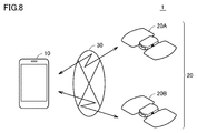
- FIG. 8 is a diagram showing a schematic configuration of a treatment system 1 according to the second embodiment.
- treatment system 1 includes a terminal device 10 which is a user terminal, electrotherapy devices 20A and 20B, and a network 30.
- the electrotherapy device 20 when describing the configuration and function common to each of the electrotherapy devices 20A and 20B, they are collectively referred to as "the electrotherapy device 20".
- the electric therapy device 20 is of a cordless type and has a pad, a holder, and a main body united together in use, and these parts are combined to perform treatment.
- the specific configuration of the electrotherapy device 20 will be described later.
- the terminal device 10 is, for example, a smartphone provided with a touch panel.
- a smart phone is explained as a representative example of a "terminal device.”
- the terminal device may be another terminal device such as a foldable mobile phone, a tablet terminal device, a personal computer (PC), a personal data assistance (PDA) or the like.
- PC personal computer
- PDA personal data assistance
- a network 30 for connecting the terminal device 10 and the electrotherapy device 20 employs a short distance wireless communication method, and typically, BLE (Bluetooth (registered trademark) low energy) is employed. Therefore, the terminal device 10 and the electrotherapy device 20 are BLE devices having a function of performing wireless communication using BLE.
- the network 30 is not limited to this, and other wireless communication methods such as Bluetooth (registered trademark) and wireless LAN (local area network) may be adopted.
- the terminal device 10 instructs the paired electrotherapy devices 20A and 20B using the installed application.
- the terminal device 10 also displays various information on the display 158 to notify the user of necessary information.
- the terminal device 10 may display the information received from the electrotherapy device 20 on the display 158.
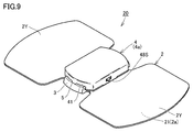
- FIG. 9 is a perspective view showing an example of the configuration of the electrotherapy device 20 according to the second embodiment.
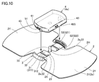
- FIG. 10 is a perspective view showing a state in which main body 4 provided in electric therapy device 20 according to the second embodiment is separated from holder 3 and pad 2.
- the electrotherapy device 20 is a so-called cordless type low frequency therapy device, and includes a pad 2, a holder 3, and a main body 4.
- the pad 2 has a sheet-like shape and is attached to the user's body.
- a conductive layer 2 a is provided on the surface (lower surface) of the body side 21 facing the body among the outer surfaces of the pad 2.
- the pad 2 is attached on the skin of the user using a conductive gel or the like, and a low frequency pulse current is supplied to the user through the conductive layer 2a.
- pad 2 has mounting portion 2X and treatment portion 2Y.
- the mounting portion 2X is held by the holder 3.
- the mounting portion 2X is provided with a window portion 23 and a through hole 2H.
- the positioning projection 312 of the holder 3 is disposed inside the window portion 23.
- the interlock pin 33 of the holder 3 is inserted into the through hole 2H.
- the treatment portion 2Y is provided on the left and right sides of the attachment portion 2X, and the conductive layer 2a is exposed on the body side 21 of the treatment portion 2Y.
- the conductive layer 2 a is also exposed on the surface of the mounting portion 2 ⁇ / b> X facing the main body portion 4, and the exposed portion constitutes the pad side electrode portion 22.
- the pad-side electrode portion 22 is formed for electrical connection with the main-body-side electrode portion 43, and the conductive layer 2a corresponding to one electrode portion (for example, positive electrode) is exposed at one end of the attachment portion 2X.
- the conductive layer 2a corresponding to the other electrode portion (for example, the negative electrode) is exposed.
- the holder 3 includes a pad holding portion 31 having a plate-like shape, and a pair of wall portions 32 rising from both ends of the pad holding portion 31.
- the mounting portion 2 ⁇ / b> X of the pad 2 is disposed on the upper surface 311 of the pad holding portion 31.
- a double-sided adhesive tape, a glue, an adhesive agent, etc. are arrange
- the pad holding portion 31 is provided with a positioning protrusion 312.
- the pad 2 is positioned with respect to the holder 3 by aligning the inner peripheral edge of the window 23 provided in the pad 2 with the positioning protrusion 312.
- An interlock pin 33 is also provided at the center of the pad holder 31. When attaching the pad 2 to the holder 3, the interlock pin 33 is inserted into the through hole 2H.
- the pad 2 is a consumable item, the pad 2 is removable from the main body 4 at the time of replacement. In the present embodiment, both are integrated by holding the pad 2 by the holder 3, and the main body 4 is attached to and detached from the pad 2 and the holder 3. Although the pad 2 is replaced with the holder 3, it is not impossible to reuse the holder 3 as needed.
- main body 4 includes a case 4a having a substantially rectangular parallelepiped shape as an exterior body.
- An induction engaging portion 5 (FIG. 9) is formed between the case 4 a and the holder 3, and the main body 4 (case 4 a) is detachably attached to the holder 3.
- the guiding engagement portion 5 is composed of a protrusion 51 (FIG. 10) formed on the side surface 41 of the case 4 a and a groove 52 (FIG. 10) formed on the wall portion 32 of the holder 3.
- groove 52 includes a longitudinal groove 521 and a lateral groove 522.
- the longitudinal groove 521 is formed in the vertical direction, and the upper side is open.
- the lateral groove 522 is formed in the lateral direction, and both ends are open.
- the main body 4 supplies a low frequency pulse current to the conductive layer 2 a of the pad 2 in a state of being attached to the holder 3.
- the main body 4 includes a pair of main body side electrode portions 43, a substrate (not shown), an electric circuit (not shown), and an interlock mechanism (not shown).
- the electrical circuit includes various control devices and is mounted on the surface of the substrate.
- the control device includes a processor for executing various processes, a memory for storing programs and data, a communication interface for wirelessly communicating various data with the terminal device 10, boosting of the power supply voltage, and low frequency pulse current Includes a waveform generation output device and the like for generating and outputting the current.
- the substrate, the electric circuit, and the interlock mechanism are provided inside the main body 4 (case 4a).
- a power supply (not shown) such as a battery is also provided inside the main body 4 (case 4a).
- a switch 48S On the outside of the case 4a, a switch 48S, a display unit (not shown) such as an LED (light emitting diode), and a button (not shown) are provided.
- the tip end of the main body side electrode portion 43 abuts on the pad side electrode portion 22.
- the main body side electrode portion 43 and the pad side electrode portion 22 are electrically connected, and the electric circuit can supply the low frequency pulse current to the pad side electrode portion 22.
- FIG. 11 is a block diagram showing an example of a hardware configuration of terminal apparatus 10 according to the second embodiment.
- the terminal device 10 includes, as main components, a processor 152, a memory 154, an input device 156, a display 158, a wireless communication unit 160, and a memory interface (I / F) 164.
- a communication interface (I / F) 166, a speaker 168, and a microphone 170 are included.
- the processor 152 is typically an arithmetic processing unit such as a CPU or an MPU.
- the memory 154 is realized by a RAM, a ROM, a flash memory or the like.
- the input device 156 receives an operation input to the terminal device 10.
- the input device 156 is realized by a touch panel.
- the touch panel is provided on the display 158 having a function as a display unit, and is, for example, a capacitive type.
- the touch panel detects a touch operation on the touch panel by an external object every predetermined time, and inputs touch coordinates to the processor 152.
- the input device 156 may include a button or the like.
- the wireless communication unit 160 is connected to the mobile communication network via the communication antenna 162 to transmit and receive signals for wireless communication. Thereby, the terminal device 10 can communicate with another communication device via a mobile communication network such as LTE (Long Term Evolution), for example.
- LTE Long Term Evolution
- the memory interface 164 reads data from the external storage medium 165.
- the processor 152 reads the data stored in the storage medium 165 via the memory interface 164 and stores the data in the memory 154.
- the processor 152 reads data from the memory 154 and stores the data in the external storage medium 165 via the memory interface 164.
- the storage medium 165 is a non-volatile memory such as a CD (Compact Disc), a DVD (Digital Versatile Disk), a BD (Blu-ray (registered trademark) Disc), a USB (Universal Serial Bus) memory, and an SD (Secure Digital) memory card. Includes media for storing programs.
- a CD Compact Disc
- DVD Digital Versatile Disk
- BD Blu-ray (registered trademark) Disc
- USB Universal Serial Bus
- SD Secure Digital
- the communication interface (I / F) 166 is a communication interface for exchanging various data between the terminal device 10 and the electrotherapy device 20, and is realized by an adapter, a connector, or the like.
- a communication method for example, a wireless communication method by BLE, a wireless LAN or the like is adopted.
- the speaker 168 converts the audio signal supplied from the processor 152 into audio and outputs the audio to the outside of the terminal device 10.
- the microphone 170 receives an audio input to the terminal device 10 and provides an audio signal corresponding to the audio input to the processor 152.
- the electric therapy device 20 has the same configuration as the treatment content setting unit 302, the output control unit 304, and the treatment execution unit 306 in the configuration of the electric treatment device 200 shown in FIG. Each of these configurations is realized by the control device included in the main unit 4 of the electrotherapy device 20.
- the display control unit 308 illustrated in FIG. 5 is realized by the processor 152 of the terminal device 10.
- the user has given various instructions to the electrotherapy device 200 via the input interface 230.
- the user gives various instructions to the terminal device 10 via the input device 156, and the instruction is transmitted from the terminal device 10 to the electrotherapy device 20, thereby indirectly to the electrotherapy device 20.
- a treatment current is supplied to the treatment site by applying a voltage between the electrode of one pad 270 of positive polarity and the electrode of the other pad 270 of negative polarity.
- the treatment current at the treatment site Flow.
- various information stored in the memory 220 for the electrotherapy device 200 to execute the above-described processing in the first embodiment is typically stored in the memory of the electrotherapy device 20. However, part of the information may be stored in the memory 154 of the terminal device 10.
- the electrotherapy device 20 is configured to transmit information necessary to notify the user, information to be stored in the terminal device 10, and the like to the terminal device 10. Thereby, the terminal device 10 can display on the display 158 a selection screen of the adjustment pattern of the electric stimulation intensity described above, a permission screen for requesting permission for the execution of treatment using the electric stimulation intensity ST, and the like.
- a program that causes a computer to function and executes control as described in the above-described flowchart.
- a program is recorded on a non-temporary computer readable recording medium such as a flexible disk attached to a computer, a CD (Compact Disk Read Only Memory), a secondary storage device, a main storage device, and a memory card. It can also be provided as a program product.
- the program can be provided by being recorded in a recording medium such as a hard disk built in the computer.
- the program can be provided by downloading via a network.
- the program may call a required module among program modules provided as a part of an operating system (OS) of a computer in a predetermined arrangement at a predetermined timing to execute processing.
- OS operating system
- the program itself does not include the above module, and the processing is executed in cooperation with the OS.
- a program that does not include such a module may also be included in the program according to the present embodiment.
- the program according to the present embodiment may be provided by being incorporated into a part of another program. Also in this case, the program itself does not include a module included in the other program, and the process is executed in cooperation with the other program. Programs incorporated into such other programs may also be included in the program according to the present embodiment.
- the present embodiment includes the following disclosure.
- a treatment content setting unit (302) configured to set the treatment content designated by the user;
- a treatment execution unit (306) for treating the site according to the treatment content by controlling pulse voltages applied to a plurality of electrodes in contact with the body site of the user;
- an output control unit (304) for outputting a pulse voltage of a first frequency included in a predetermined frequency range before the treatment execution unit (306) performs treatment of the site.
- the treatment content setting unit (302) receives an input of the electric stimulation intensity desired by the user, The electric treatment device (200), wherein the treatment execution unit (306) performs treatment of the site by changing a pulse voltage corresponding to the electric stimulation intensity desired by the user in the predetermined frequency range.
- the treatment content setting unit (302) receives an input of the first electric stimulation intensity desired by the user,
- the output control unit (304) outputs a pulse voltage corresponding to the first electrical stimulation intensity at a second frequency included in the frequency range,
- the therapy execution unit (306 The electrotherapeutic device (200) according to configuration 1 or 2, wherein the treatment of the site is performed by changing a pulse voltage corresponding to the first electrical stimulation intensity in the frequency range.
- the first frequency is a maximum frequency in the predetermined frequency range, 7.
- the treatment execution unit (306) sweeps in the direction of the frequency increasing from the minimum frequency to the maximum frequency in the frequency range, and by sweeping in the direction of the frequency decreasing from the maximum frequency to the minimum frequency
- the electrotherapy device (200) according to any one of arrangements 1-5, wherein the frequency of the pulse voltage is changed.
- a method of controlling an electrotherapy device comprising Setting the treatment content specified by the user; Performing a treatment of the site according to the treatment content by controlling a pulse voltage applied to a plurality of electrodes in contact with the site of the user's body; Outputting a pulse voltage of a first frequency included in a predetermined frequency range before the treatment of the site is performed by the performing step; When the pulse voltage of the first frequency is output, the setting includes receiving an input of a user's desired electric stimulation strength, The control method may include performing treatment of the site by changing a pulse voltage corresponding to the user's desired electrical stimulation intensity in the predetermined frequency range.
- the treatment content setting unit (302) receives an input of an electrical stimulation intensity desired by the user via the terminal device (10), The treatment system (1), wherein the treatment execution unit (306) performs treatment of the site by changing a pulse voltage corresponding to the electric stimulation intensity desired by the user in the predetermined frequency range.
- Reference Signs List 1 treatment system 2,270 pad, 2H through hole, 2X attachment portion, 2Y treatment portion, 2a conductive layer, 3 holder, 4 main body portion, 4a case, 5 induction engagement portion, 10 terminal devices, 20A, 20B, 200 Electric therapy device, 21 body side, 22 pad side electrode portion, 23 window portion, 30 network, 31 pad holding portion, 32 wall portion, 33 interlock pin, 40 supporter, 41 side surface, 43 body portion side electrode portion, 48S Switch, 51 protrusion, 52 groove, 152, 210 processor, 154, 220 memory, 156 input device, 158, 260 display, 160 wireless communication unit, 162 communication antenna, 164 memory interface, 165 storage medium, 168 speaker, 170 microphone, 205 control devices, Reference Signs List 30 input interface 240 power supply unit 250 waveform generation output device 280 code 282 plug 302 treatment content setting unit 304 output control unit 306 treatment execution unit 308 display control unit 311 upper surface 312 positioning projection 521 vertical Groove, 522 Horizontal groove.
Landscapes
- Health & Medical Sciences (AREA)
- Life Sciences & Earth Sciences (AREA)
- General Health & Medical Sciences (AREA)
- Engineering & Computer Science (AREA)
- Biomedical Technology (AREA)
- Nuclear Medicine, Radiotherapy & Molecular Imaging (AREA)
- Radiology & Medical Imaging (AREA)
- Animal Behavior & Ethology (AREA)
- Public Health (AREA)
- Veterinary Medicine (AREA)
- Heart & Thoracic Surgery (AREA)
- Biophysics (AREA)
- Pain & Pain Management (AREA)
- Physical Education & Sports Medicine (AREA)
- Electrotherapy Devices (AREA)
Priority Applications (3)
| Application Number | Priority Date | Filing Date | Title |
|---|---|---|---|
| CN201880064818.6A CN111372651B (zh) | 2017-11-06 | 2018-10-19 | 电疗仪、控制方法以及治疗系统 |
| DE112018004703.2T DE112018004703B4 (de) | 2017-11-06 | 2018-10-19 | Elektrische behandlungsvorrichtung, steuerverfahren und behandlungssystem |
| US16/860,171 US11826567B2 (en) | 2017-11-06 | 2020-04-28 | Electrical treatment device, control method, and treatment system |
Applications Claiming Priority (2)
| Application Number | Priority Date | Filing Date | Title |
|---|---|---|---|
| JP2017213778A JP7087346B2 (ja) | 2017-11-06 | 2017-11-06 | 電気治療器、制御方法、および治療システム |
| JP2017-213778 | 2017-11-06 |
Related Child Applications (1)
| Application Number | Title | Priority Date | Filing Date |
|---|---|---|---|
| US16/860,171 Continuation US11826567B2 (en) | 2017-11-06 | 2020-04-28 | Electrical treatment device, control method, and treatment system |
Publications (1)
| Publication Number | Publication Date |
|---|---|
| WO2019087823A1 true WO2019087823A1 (ja) | 2019-05-09 |
Family
ID=66331864
Family Applications (1)
| Application Number | Title | Priority Date | Filing Date |
|---|---|---|---|
| PCT/JP2018/039032 Ceased WO2019087823A1 (ja) | 2017-11-06 | 2018-10-19 | 電気治療器、制御方法、および治療システム |
Country Status (5)
| Country | Link |
|---|---|
| US (1) | US11826567B2 (enExample) |
| JP (1) | JP7087346B2 (enExample) |
| CN (1) | CN111372651B (enExample) |
| DE (1) | DE112018004703B4 (enExample) |
| WO (1) | WO2019087823A1 (enExample) |
Families Citing this family (5)
| Publication number | Priority date | Publication date | Assignee | Title |
|---|---|---|---|---|
| JP7070089B2 (ja) | 2018-05-24 | 2022-05-18 | オムロンヘルスケア株式会社 | 電気治療器、および治療システム |
| JP7493700B2 (ja) * | 2019-07-26 | 2024-06-03 | 伊藤超短波株式会社 | 顎関節治療器 |
| JP7433855B2 (ja) * | 2019-11-25 | 2024-02-20 | ヤーマン株式会社 | サポーター器具 |
| CN112704628B (zh) * | 2020-12-10 | 2023-04-21 | 未来穿戴技术有限公司 | 手指按摩设备的控制方法、相关装置及计算机存储介质 |
| JP2023530793A (ja) * | 2021-05-18 | 2023-07-20 | コアームーブメント カンパニー リミテッド | 水中で使用可能な電気刺激システム |
Citations (4)
| Publication number | Priority date | Publication date | Assignee | Title |
|---|---|---|---|---|
| JP2002248175A (ja) * | 2001-02-23 | 2002-09-03 | Minato Ikagaku Kk | 電気刺激装置 |
| JP2004337298A (ja) * | 2003-05-14 | 2004-12-02 | Ito Choutanpa Kk | 低周波治療装置、方法、プログラム及び記録媒体 |
| JP2005252449A (ja) * | 2004-03-02 | 2005-09-15 | Hitachi Software Eng Co Ltd | 携帯通信端末及び低周波パルス電圧制御方法 |
| JP2016073372A (ja) * | 2014-10-03 | 2016-05-12 | 株式会社 リブレックス | 電位治療器 |
Family Cites Families (7)
| Publication number | Priority date | Publication date | Assignee | Title |
|---|---|---|---|---|
| JP2000014803A (ja) | 1998-06-29 | 2000-01-18 | Omron Corp | 低周波治療器 |
| US6631297B1 (en) | 2000-05-18 | 2003-10-07 | Seung-Kee Mo | Electrical clinical apparatus and electrical stimulation method using variant assignment method |
| JP2002200179A (ja) * | 2000-10-27 | 2002-07-16 | M Silverstone Leon | 慢性疼痛症候群、震せん、痴呆、および関連疾患を治療する装置、並びに、高周波数、高強度の経皮電気刺激を用いて電気麻酔を誘発する装置 |
| JP4480992B2 (ja) | 2003-12-09 | 2010-06-16 | ミナト医科学株式会社 | バランス調節機能付き電気刺激装置 |
| WO2007081284A1 (en) * | 2006-01-13 | 2007-07-19 | Raynet Technologies Pte Ltd | Systems and methods of electronic muscle stimulation |
| JP2009160328A (ja) * | 2008-01-10 | 2009-07-23 | Omron Healthcare Co Ltd | 治療器 |
| US8843209B2 (en) * | 2012-04-27 | 2014-09-23 | Medtronic, Inc. | Ramping parameter values for electrical stimulation therapy |
-
2017
- 2017-11-06 JP JP2017213778A patent/JP7087346B2/ja active Active
-
2018
- 2018-10-19 WO PCT/JP2018/039032 patent/WO2019087823A1/ja not_active Ceased
- 2018-10-19 CN CN201880064818.6A patent/CN111372651B/zh active Active
- 2018-10-19 DE DE112018004703.2T patent/DE112018004703B4/de active Active
-
2020
- 2020-04-28 US US16/860,171 patent/US11826567B2/en active Active
Patent Citations (4)
| Publication number | Priority date | Publication date | Assignee | Title |
|---|---|---|---|---|
| JP2002248175A (ja) * | 2001-02-23 | 2002-09-03 | Minato Ikagaku Kk | 電気刺激装置 |
| JP2004337298A (ja) * | 2003-05-14 | 2004-12-02 | Ito Choutanpa Kk | 低周波治療装置、方法、プログラム及び記録媒体 |
| JP2005252449A (ja) * | 2004-03-02 | 2005-09-15 | Hitachi Software Eng Co Ltd | 携帯通信端末及び低周波パルス電圧制御方法 |
| JP2016073372A (ja) * | 2014-10-03 | 2016-05-12 | 株式会社 リブレックス | 電位治療器 |
Also Published As
| Publication number | Publication date |
|---|---|
| JP2019083995A (ja) | 2019-06-06 |
| CN111372651B (zh) | 2023-09-26 |
| DE112018004703T5 (de) | 2020-06-18 |
| CN111372651A (zh) | 2020-07-03 |
| JP7087346B2 (ja) | 2022-06-21 |
| DE112018004703B4 (de) | 2024-09-12 |
| US20200254253A1 (en) | 2020-08-13 |
| US11826567B2 (en) | 2023-11-28 |
Similar Documents
| Publication | Publication Date | Title |
|---|---|---|
| JP6733513B2 (ja) | 電気治療器、および治療システム | |
| US11826567B2 (en) | Electrical treatment device, control method, and treatment system | |
| JP6733514B2 (ja) | 電気治療器、および治療システム | |
| CN110831657B (zh) | 终端装置、控制方法、计算机可读取记录介质以及治疗系统 | |
| US11324951B2 (en) | Electrical treatment device, control method, and treatment system | |
| JP6733555B2 (ja) | 電気治療器、システムおよびプログラム | |
| CN110891649B (zh) | 电疗仪、电子设备及终端装置 | |
| CN112584893B (zh) | 终端装置、电疗仪及治疗系统 | |
| US11992680B2 (en) | Electrical treatment device and treatment system | |
| JP7087622B2 (ja) | 電気治療器、および治療システム | |
| US20250205488A1 (en) | Low frequency therapeutic apparatus, control method, and control recording medium | |
| JP2024108224A (ja) | 電気刺激装置及び電気刺激条件の設定方法 | |
| WO2021200155A1 (ja) | 電気治療器 |
Legal Events
| Date | Code | Title | Description |
|---|---|---|---|
| 121 | Ep: the epo has been informed by wipo that ep was designated in this application |
Ref document number: 18873068 Country of ref document: EP Kind code of ref document: A1 |
|
| 122 | Ep: pct application non-entry in european phase |
Ref document number: 18873068 Country of ref document: EP Kind code of ref document: A1 |