WO2019087455A1 - 金属部材の溶接構造および溶接方法 - Google Patents
金属部材の溶接構造および溶接方法 Download PDFInfo
- Publication number
- WO2019087455A1 WO2019087455A1 PCT/JP2018/023566 JP2018023566W WO2019087455A1 WO 2019087455 A1 WO2019087455 A1 WO 2019087455A1 JP 2018023566 W JP2018023566 W JP 2018023566W WO 2019087455 A1 WO2019087455 A1 WO 2019087455A1
- Authority
- WO
- WIPO (PCT)
- Prior art keywords
- solidified portion
- solidified
- laser beam
- scan
- welding
- Prior art date
Links
Images


Classifications
-
- B—PERFORMING OPERATIONS; TRANSPORTING
- B23—MACHINE TOOLS; METAL-WORKING NOT OTHERWISE PROVIDED FOR
- B23K—SOLDERING OR UNSOLDERING; WELDING; CLADDING OR PLATING BY SOLDERING OR WELDING; CUTTING BY APPLYING HEAT LOCALLY, e.g. FLAME CUTTING; WORKING BY LASER BEAM
- B23K26/00—Working by laser beam, e.g. welding, cutting or boring
- B23K26/20—Bonding
- B23K26/21—Bonding by welding
- B23K26/24—Seam welding
- B23K26/244—Overlap seam welding
-
- B—PERFORMING OPERATIONS; TRANSPORTING
- B23—MACHINE TOOLS; METAL-WORKING NOT OTHERWISE PROVIDED FOR
- B23K—SOLDERING OR UNSOLDERING; WELDING; CLADDING OR PLATING BY SOLDERING OR WELDING; CUTTING BY APPLYING HEAT LOCALLY, e.g. FLAME CUTTING; WORKING BY LASER BEAM
- B23K26/00—Working by laser beam, e.g. welding, cutting or boring
- B23K26/20—Bonding
- B23K26/21—Bonding by welding
- B23K26/24—Seam welding
-
- B—PERFORMING OPERATIONS; TRANSPORTING
- B23—MACHINE TOOLS; METAL-WORKING NOT OTHERWISE PROVIDED FOR
- B23K—SOLDERING OR UNSOLDERING; WELDING; CLADDING OR PLATING BY SOLDERING OR WELDING; CUTTING BY APPLYING HEAT LOCALLY, e.g. FLAME CUTTING; WORKING BY LASER BEAM
- B23K26/00—Working by laser beam, e.g. welding, cutting or boring
- B23K26/20—Bonding
- B23K26/32—Bonding taking account of the properties of the material involved
- B23K26/323—Bonding taking account of the properties of the material involved involving parts made of dissimilar metallic material
-
- H—ELECTRICITY
- H01—ELECTRIC ELEMENTS
- H01M—PROCESSES OR MEANS, e.g. BATTERIES, FOR THE DIRECT CONVERSION OF CHEMICAL ENERGY INTO ELECTRICAL ENERGY
- H01M50/00—Constructional details or processes of manufacture of the non-active parts of electrochemical cells other than fuel cells, e.g. hybrid cells
- H01M50/50—Current conducting connections for cells or batteries
- H01M50/502—Interconnectors for connecting terminals of adjacent batteries; Interconnectors for connecting cells outside a battery casing
- H01M50/507—Interconnectors for connecting terminals of adjacent batteries; Interconnectors for connecting cells outside a battery casing comprising an arrangement of two or more busbars within a container structure, e.g. busbar modules
-
- H—ELECTRICITY
- H01—ELECTRIC ELEMENTS
- H01M—PROCESSES OR MEANS, e.g. BATTERIES, FOR THE DIRECT CONVERSION OF CHEMICAL ENERGY INTO ELECTRICAL ENERGY
- H01M50/00—Constructional details or processes of manufacture of the non-active parts of electrochemical cells other than fuel cells, e.g. hybrid cells
- H01M50/50—Current conducting connections for cells or batteries
- H01M50/502—Interconnectors for connecting terminals of adjacent batteries; Interconnectors for connecting cells outside a battery casing
- H01M50/514—Methods for interconnecting adjacent batteries or cells
- H01M50/516—Methods for interconnecting adjacent batteries or cells by welding, soldering or brazing
-
- H—ELECTRICITY
- H01—ELECTRIC ELEMENTS
- H01M—PROCESSES OR MEANS, e.g. BATTERIES, FOR THE DIRECT CONVERSION OF CHEMICAL ENERGY INTO ELECTRICAL ENERGY
- H01M50/00—Constructional details or processes of manufacture of the non-active parts of electrochemical cells other than fuel cells, e.g. hybrid cells
- H01M50/50—Current conducting connections for cells or batteries
- H01M50/502—Interconnectors for connecting terminals of adjacent batteries; Interconnectors for connecting cells outside a battery casing
- H01M50/521—Interconnectors for connecting terminals of adjacent batteries; Interconnectors for connecting cells outside a battery casing characterised by the material
- H01M50/522—Inorganic material
-
- H—ELECTRICITY
- H01—ELECTRIC ELEMENTS
- H01M—PROCESSES OR MEANS, e.g. BATTERIES, FOR THE DIRECT CONVERSION OF CHEMICAL ENERGY INTO ELECTRICAL ENERGY
- H01M50/00—Constructional details or processes of manufacture of the non-active parts of electrochemical cells other than fuel cells, e.g. hybrid cells
- H01M50/50—Current conducting connections for cells or batteries
- H01M50/528—Fixed electrical connections, i.e. not intended for disconnection
-
- B—PERFORMING OPERATIONS; TRANSPORTING
- B23—MACHINE TOOLS; METAL-WORKING NOT OTHERWISE PROVIDED FOR
- B23K—SOLDERING OR UNSOLDERING; WELDING; CLADDING OR PLATING BY SOLDERING OR WELDING; CUTTING BY APPLYING HEAT LOCALLY, e.g. FLAME CUTTING; WORKING BY LASER BEAM
- B23K2101/00—Articles made by soldering, welding or cutting
- B23K2101/36—Electric or electronic devices
-
- B—PERFORMING OPERATIONS; TRANSPORTING
- B23—MACHINE TOOLS; METAL-WORKING NOT OTHERWISE PROVIDED FOR
- B23K—SOLDERING OR UNSOLDERING; WELDING; CLADDING OR PLATING BY SOLDERING OR WELDING; CUTTING BY APPLYING HEAT LOCALLY, e.g. FLAME CUTTING; WORKING BY LASER BEAM
- B23K2103/00—Materials to be soldered, welded or cut
- B23K2103/08—Non-ferrous metals or alloys
- B23K2103/10—Aluminium or alloys thereof
-
- B—PERFORMING OPERATIONS; TRANSPORTING
- B23—MACHINE TOOLS; METAL-WORKING NOT OTHERWISE PROVIDED FOR
- B23K—SOLDERING OR UNSOLDERING; WELDING; CLADDING OR PLATING BY SOLDERING OR WELDING; CUTTING BY APPLYING HEAT LOCALLY, e.g. FLAME CUTTING; WORKING BY LASER BEAM
- B23K2103/00—Materials to be soldered, welded or cut
- B23K2103/08—Non-ferrous metals or alloys
- B23K2103/12—Copper or alloys thereof
-
- B—PERFORMING OPERATIONS; TRANSPORTING
- B23—MACHINE TOOLS; METAL-WORKING NOT OTHERWISE PROVIDED FOR
- B23K—SOLDERING OR UNSOLDERING; WELDING; CLADDING OR PLATING BY SOLDERING OR WELDING; CUTTING BY APPLYING HEAT LOCALLY, e.g. FLAME CUTTING; WORKING BY LASER BEAM
- B23K2103/00—Materials to be soldered, welded or cut
- B23K2103/18—Dissimilar materials
-
- H—ELECTRICITY
- H01—ELECTRIC ELEMENTS
- H01M—PROCESSES OR MEANS, e.g. BATTERIES, FOR THE DIRECT CONVERSION OF CHEMICAL ENERGY INTO ELECTRICAL ENERGY
- H01M50/00—Constructional details or processes of manufacture of the non-active parts of electrochemical cells other than fuel cells, e.g. hybrid cells
- H01M50/50—Current conducting connections for cells or batteries
- H01M50/543—Terminals
- H01M50/552—Terminals characterised by their shape
- H01M50/553—Terminals adapted for prismatic, pouch or rectangular cells
-
- H—ELECTRICITY
- H01—ELECTRIC ELEMENTS
- H01M—PROCESSES OR MEANS, e.g. BATTERIES, FOR THE DIRECT CONVERSION OF CHEMICAL ENERGY INTO ELECTRICAL ENERGY
- H01M50/00—Constructional details or processes of manufacture of the non-active parts of electrochemical cells other than fuel cells, e.g. hybrid cells
- H01M50/50—Current conducting connections for cells or batteries
- H01M50/543—Terminals
- H01M50/562—Terminals characterised by the material
-
- Y—GENERAL TAGGING OF NEW TECHNOLOGICAL DEVELOPMENTS; GENERAL TAGGING OF CROSS-SECTIONAL TECHNOLOGIES SPANNING OVER SEVERAL SECTIONS OF THE IPC; TECHNICAL SUBJECTS COVERED BY FORMER USPC CROSS-REFERENCE ART COLLECTIONS [XRACs] AND DIGESTS
- Y02—TECHNOLOGIES OR APPLICATIONS FOR MITIGATION OR ADAPTATION AGAINST CLIMATE CHANGE
- Y02E—REDUCTION OF GREENHOUSE GAS [GHG] EMISSIONS, RELATED TO ENERGY GENERATION, TRANSMISSION OR DISTRIBUTION
- Y02E60/00—Enabling technologies; Technologies with a potential or indirect contribution to GHG emissions mitigation
- Y02E60/10—Energy storage using batteries
Definitions
- the present disclosure relates to a welding structure and a welding method of metal members in which a first member is overlapped and welded on a second member.
- a plurality of battery cells are connected by a bus bar of a metal plate.
- the bus bars are connected by laser welding to the electrode terminals of the battery cells that constitute the battery system.
- the bus bar is disposed on the flat portion of the electrode terminal of the battery cell, and laser light is irradiated from the surface side of the bus bar to melt and connect both the electrode terminal and the bus bar.
- the battery has a positive electrode and a negative electrode.
- an aluminum terminal is used on the positive electrode side, and a nickel-plated copper terminal is used on the negative electrode side. Since the bus bars connect adjacent battery cells in series or in parallel, electrode terminals of at least two battery cells are connected to one bus bar.
- the aluminum terminal on the positive electrode side may be welded to the aluminum side of the clad material, and the copper terminal on the negative electrode side may be welded to the copper side of the clad material Therefore, it is welding of the same kind metal respectively, and there is no technical difficulty in particular.
- this clad material is formed by overlapping thin plates of aluminum and copper so that the joints overlap, and pressure is applied while applying heat, so the process cost is high and the direct material cost is also expensive. Cost reduction can not be achieved.
- dissimilar metal welding welding is performed by melting different metal materials together, mixing them and then solidifying them.
- dissimilar welding of aluminum and copper when the alloy is sufficiently heated and melted for a certain time at a certain temperature or higher, an intermetallic compound having a certain ratio of a composition of aluminum and copper is formed. .
- This intermetallic compound is a very hard layer with few lattice defects but becomes brittle and broken when stress is applied. For this reason, simply increasing the melt volume does not mean that high bonding strength can be obtained, and it is difficult to stably obtain high bonding strength.
- Patent Document 1 In the welding of dissimilar materials, as a structure for measures against the strength, a welding structure in which a high hardness layer and a low hardness layer are alternately and repeatedly laminated in the advancing direction of welding has been invented (see Patent Document 1).
- FIG. 10B is a cross-sectional view taken along line AA of FIG. 10A.
- a first member 21 of ferritic stainless steel or low carbon steel and a second member 22 of martensitic stainless steel or high carbon steel are superimposed, and the surface of the first member 21 is irradiated with laser light.
- the melted and solidified portion indicated by the hatched area is a reverse direction in which the width gradually decreases from the surface side of the first member 21 toward the inside It has a triangular cross-sectional structure.
- the molten and solidified part has a low hardness layer 23 on the surface side and a high hardness layer 24 on the inside side.
- the high hardness layer 24 is formed by alternately and repeatedly laminating the first layer 25 and the second layer 26 whose hardness is lower than that in the welding direction.
- the surface of the first member 21 is pulsedly irradiated with laser light.
- a first molten portion formed by melting the first member 21 and the second member 22 by the laser beam of the first pulse is formed.
- the position is slightly shifted to start irradiation of the laser light of the second pulse.
- the second melting portion is formed to partially overlap the first melting portion.
- the laser beam of the third and subsequent pulses is irradiated while being turned on and off at predetermined intervals, to form a welded structure.
- the cross section in the direction perpendicular to the direction of progress of welding (FIG. 10B) has an inverted triangle structure, and the cross section in the direction of travel (FIG. 10A) has the first layer 25 in the direction of travel. And the second layer 26 are repeatedly laminated. The melting depths of the first layer 25 and the second layer 26 are approximately the same.
- the welded structure of the metal member of the present disclosure includes a first member, a second member, a first solidification portion, a second solidification portion, and a third solidification portion.
- the first member has a first surface and a second surface opposite to the first surface, and includes a metal member.
- the second member is stacked on the second surface of the first member and includes a metal member.
- the first solidified portion is present from the first surface to the second surface of the first member.
- the second solidification section has a first end in the second member and a second end connected to the first solidification section.
- the third solidification section has a first end in the second member and a second end connected to the first solidification section.
- the third coagulation part is shorter than the second coagulation part.
- the second solidified portion and the third solidified portion are separated from each other in the second member.
- the welding method of the metal member of this indication is a welding method of the 1st member containing a metal member, and the 2nd member containing a metal member.
- the first member has a first surface and a second surface opposite to the first surface.
- the second member is stacked on the second surface of the first member.
- the welding method of metal members is A first scan for scanning the first laser beam along a first trajectory; A second scan that scans the second laser beam along a second trajectory different from the first trajectory at a higher power or a lower velocity than the first laser beam; Have.
- the first scan and the second scan are alternately performed at least once each.
- the metal of the first member is melted and solidified from the first surface to the second surface of the first member by the first scan and the second scan to form a first solidified portion.
- the metal of the second member is melted and then solidified so that the first end exists in the second member and the second end is connected to the first solidified portion Form a second solidification part.
- the metal of the second member is melted and then solidified so that the first end exists in the second member and the second end is connected to the first solidified portion Form the third coagulation part.
- the second scan with the second laser light is performed on the second track in which the melted portions of the second member by the first scan move to a distance where they can be separated from each other.
- FIG. 1A is a top view showing a laser irradiation pattern of Example 1 in Embodiment 1.
- FIG. 1B is a cross-sectional view in the direction perpendicular to the scanning direction showing the welded structure in the case where there is no gap in Example 1.
- FIG. 2 is a cross-sectional view perpendicular to the scanning direction showing the welded structure in the case where there is a gap in the first embodiment.
- FIG. 3A is a cross-sectional view in the direction perpendicular to the scanning direction showing the welded structure in the case where there is no gap in Example 2 in the first embodiment.
- FIG. 3B is a cross-sectional view perpendicular to the scanning direction showing the welded structure in the case where there is a gap in Example 2.
- FIG. 4A is a cross-sectional view in the direction perpendicular to the scanning direction showing the welded structure in the case where there is no gap in Example 3 in the first embodiment.
- FIG. 4B is a cross-sectional view in the direction perpendicular to the scanning direction showing the welded structure in the case where there is a gap in Example 3.
- 5A is a top view showing a laser irradiation pattern of Example 4 in Embodiment 2.
- FIG. FIG. 5B is a cross-sectional view in the direction perpendicular to the scanning direction showing the welded structure in the case where there is no gap in Example 4.
- FIG. 5C is a cross-sectional view in the direction perpendicular to the scanning direction showing the welded structure in the case where there is a gap in Example 4.
- FIG. 6A is a top view showing a laser irradiation pattern of Example 5 in Embodiment 2.
- FIG. 6B is a cross-sectional view in the direction perpendicular to the scanning direction showing the welded structure in the case where there is no gap in Example 5.
- FIG. 6C is a cross-sectional view perpendicular to the scanning direction showing the welded structure in the case where there is a gap in Example 5.
- FIG. 7A is a top view showing a laser irradiation pattern of Examples 6, 7 and 8 in Embodiment 2.
- FIG. 7B is a cross-sectional view in the direction perpendicular to the scanning direction showing the welded structure in the case where there is no gap in Examples 6, 7 and 8.
- FIG. 7C is a cross-sectional view in the direction perpendicular to the scanning direction showing the welded structure in the case where there is a gap of Examples 6, 7 and 8.
- FIG. 8A is a cross-sectional view in the direction perpendicular to the scanning direction showing the welded structure in the case where there is no gap in Comparative Example 1.
- FIG. 8B is a cross-sectional view in the direction perpendicular to the scanning direction showing the welded structure in the case where there is a gap of Comparative Example 1.
- FIG. 9A is a cross-sectional view in the direction perpendicular to the scanning direction showing the welded structure in the case where there is no gap in Comparative Example 2.
- FIG. 9B is a cross-sectional view in the direction perpendicular to the scanning direction showing the welded structure in the case where there is a gap of Comparative Example 2.
- FIG. 10A is a cross-sectional view in the scanning direction showing a conventional welded structure.
- FIG. 10B is a cross-sectional view taken along line AA of FIG. 10A in a direction perpendicular to the scanning direction showing a conventional welded structure.
- Table 1 shows the relationship between the first and second embodiments and the corresponding examples.
- an example of the first member is a metal member containing aluminum
- an example of the second member is a metal member containing copper.
- the bus bar connecting the battery cells is an example of the first member
- the terminal of the cell is an example of the second member.
- the first member and the second member may be metals that form an alloy.
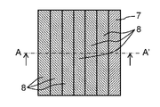
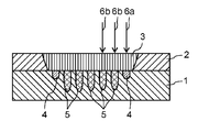
- FIG. 1 is a view for explaining a welded structure or a welded structure of a nickel-plated copper terminal of a cell and an aluminum bus bar in the first embodiment.
- FIG. 1A is a top view of the welded structure viewed from the aluminum bus bar side.
- FIG. 1B is a cross-sectional view of A-A 'of FIG. 1A.
- the connection portion of the aluminum bus bar 2 which is an example of the first member is overlapped and disposed.
- the aluminum bus bar 2 and the nickel-plated copper terminal 1 are pressed by a jig for pressing the surface portion of the aluminum bus bar 2 not irradiated with the laser downward from the upper side of FIG. Make the gap with the smallest possible.
- the bus bar 2 is to be a first solidified portion 3 which is an example of a first solidified portion.
- the melted portion in the vicinity of the interface of the nickel-plated copper terminal 1 mixes aluminum, nickel and copper in a melted state.
- the third solidified portion 4 of an alloy having a shallow depth that is, a length
- “shallow” means, as an example, a shallow case of about 5 mm in order to suppress the influence of intermetallic compound formation.
- a second laser that is higher in power than the first laser beam 6a of the trajectory 7 along the linear trajectory 8 parallel to the linear trajectory 7 and shown in FIG. 1A next to the trajectory 7. Similar to the first laser beam 6a, the light 6b is scanned from the top to the bottom of FIG. 1A, that is, from the rear to the front in FIG. 1B. The output of the second laser beam 6b is at least 105% or more of that of the first laser beam 6a.
- the second laser beam 6b moves away from the aluminum bus bar 2 so that the aluminum melted by the second laser beam 6b solidifies, and the aluminum bus bar 2 in a portion near the interface of the nickel plated copper terminal 1 from the surface of the aluminum bus bar 2 Towards the first solidified portion 3 of aluminum.
- the second solidifying portion 5 of the alloy having a deep depth is obtained by mixing the output of the second laser light 6b higher than the output of the first laser light 6a so that the second laser light 6b is separated further from the aluminum bus bar 2 It becomes.
- the distance between the track 7 of the first laser beam 6 a and the track 8 of the second laser beam 6 b adheres to each other in the first solidified portion 3 of the aluminum bus bar 2 and becomes one mass.
- the internal third coagulating portion 4 and the second coagulating portion 5 are adjusted so as to be separated from each other.
- the output of the first laser beam 6a is 1600 W
- the output of the second laser beam 6 b is 2000 W
- the distance between the third solidified portion 4 and the second solidified portion 5 is 0.25 mm
- the thickness of the aluminum bus bar is 1 mm It is.
- the melted portion melted by the first laser beam 6a is rapidly cooled to become the third solidified portion 4, but the next second laser beam 6b travels the track 8
- the third solidification unit 4 still maintains a high temperature. Therefore, the molten metal portion melted by the second laser beam 6 b becomes higher than the melting temperature when the second laser beam 6 b is scanned only once due to the heat conduction from the third solidification portion 4.
- the temperature of the molten metal portion melted by the second laser beam 6b is at a distance from the third solidification portion 4 and unmelted copper is present between the third solidification portion 4 and the molten metal portion Therefore, the amount of heat conduction to the molten metal part is attenuated by the heat conduction in the direction parallel to the laser scanning direction in this part, and the temperature rise is considerably suppressed.
- the third scan in FIG. 1B, similarly to the second laser beam 6b, scanning is performed while irradiating the third laser beam 6b along the track 8 adjacent to the track 8 already scanned.
- the first solidified portion 3 of aluminum is formed in a portion close to the surface of the aluminum bus bar 2, and the second solidification of an alloy having a deep depth is formed in the vicinity of the interface between the aluminum bus bar 2 and the copper terminal 1 of nickel plating.
- the part 5 is formed.
- the trajectory 8 parallel to the trajectory 8 is scanned with the fourth to n-th (n is an integer of 5 or more) laser beams 6b by sequentially shifting the laser beams. It becomes a welding structure where the 3rd solidification part 4 or the 2nd solidification part 5 shown in Drawing 1B is mutually separated.
- the second scan by the second laser beam 6b is performed following the first scan by the first laser beam 6a, the melted portions of the copper terminal 1 of the nickel plating by the first scan move to a distance where they can be separated from each other
- a second scan with the second laser beam 6 b is performed on the second track 8.
- the third scan by the third laser beam 6b is performed following the second scan by the second laser beam 6b, the melted portions of the copper terminal 1 of the nickel plating by the second scan move to a distance where they can be separated from each other
- the third scan with the third laser beam 6 b is performed in the third trajectory 8. The same is true thereafter.
- the third solidified portion 4 of the alloy having a shallow depth has a low temperature at the time of melting. Therefore, when the first laser beam 6a moves away from the melting portion, the melting portion solidifies quickly. For this reason, in the melting portion, the melting time is short and intermetallic compounds are difficult to be formed, and a normal alloy (that is, a solid solution containing many lattice defects) is a main component, and the lattice is shifted with respect to tensile stress. It happens easily and has a high strength weld to relieve stress.
- the second solidification part 5 with high output of the second to n-th laser light 6 b has a high output compared to the third solidification part 4 and therefore has a high melting temperature. For this reason, it takes a sufficiently long time until the second to nth laser light 6b moves and separates from the respective melted parts and then solidifies, and a large amount of intermetallic compounds having almost no lattice defects are formed. That is, more intermetallic compounds exist in the second solidified portion 5 as compared to the third solidified portion 4.
- by forming the adjacent second solidified portions 5 so as to be separated from each other heat can be released from the melted portion through the unmelted portion, compared to the case where the solidified portions are closely attached.
- the third solidified portion 4 or the second solidified portion 5 in the nickel-plated copper terminal 1 in FIG. 1B is separated from each other to form a joint. Therefore, when the third solidification section 4 and the second solidification section 5 are melted and then solidified by the first laser beam 6a and the second laser beam 6b, respectively, it is hard to be affected by the heat storage of the immediately preceding trajectories 7, 8. , Temperature rise can be suppressed. For this reason, it can suppress that many intermetallic compounds are produced
- the area ratio of the intermetallic compound occupying the cross section of the second solidified portion 5 is desirably more than 0% and 10% or less.
- the plurality of second solidification units 5 and the plurality of third solidification units 4 are connected to the same first solidification unit 3.
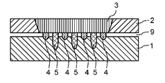
- the third solidified portion 4 maintains high strength even when the gap 9 of the aluminum bus bar 2 is hardly present on the nickel-plated copper terminal 1. it can. Further, when the gap 9 of the aluminum bus bar 2 is generated on the nickel plated copper terminal 1 as shown in FIG. 2 due to the production variation, the third solidified portion 4 having a shallow depth is almost melted with the copper terminal 1 There is almost no tensile strength due to the third solidified portion 4.
- the welded structure of the present disclosure has at least one deep second solidified portion 5 and at least one third solidified portion 4 with respect to the cross section in the direction perpendicular to the direction of progress of welding.
- the second solidification part 5 has a deep depth from the superposition position due to the irradiation of the second laser light 6 b having a large energy to be irradiated.
- the third solidification part 4 has a shallow depth from the superposition position due to the irradiation of the first laser light 6a with a small energy to be irradiated. From this, even if there is almost no gap 9 in the aluminum bus bar 2 on the nickel-plated copper terminal 1 due to production variation or a large gap 9 is generated, stable welding with high bonding strength can be suppressed at low cost. It can be manufactured using a tool.
- the third solidified portion 4 having a shallow depth is located at two or more places because the stress is not concentrated at one place but dispersed. In that case, for the same reason as in the case where the gap 9 is present, it is preferable that the deep second solidified portion 5 also be provided at two or more places.
- FIGS. 3A and 3B show the case where there are five deep second solidified parts 5 at the center and two shallow third solid parts 4 at both ends.
- FIG. 3A shows the case where there is no gap 9
- FIG. 3B shows the case where there is a gap 9.
- FIG. 3A shows the case where there is no gap 9
- FIG. 3B shows the case where there is a gap 9.
- the position of the 3rd solidification part 4 is not restricted to this, and even if the 3rd solidification part 4 is three or more, I do not care.
- FIG. 4A shows the case where there is no gap 9
- FIG. 4B shows the case where there is a gap 9.
- the third solidified portion 4 with a shallow depth and the second solidified portion 5 with a deep depth are alternately arranged along a direction (for example, a direction orthogonal to the scanning direction) with the scanning direction of the laser beams 6a and 6b.
- a direction for example, a direction orthogonal to the scanning direction
- stress of tension is uniformly distributed over the entire welded portion, so stress concentration does not occur, It is preferable because the resistance to destruction is improved and stabilized.
- Example 1 In the first embodiment, the following specific examples will be described.
- an aluminum bus bar 2 with a thickness of 1 mm is stacked on a copper terminal 1 with a thickness of 2 mm and a nickel plating thickness of 6 ⁇ m.
- the gap 9 between the copper terminal 1 and the aluminum bus bar 2 is disposed so as not to open as much as possible by a jig (not shown) pressed downward from above the aluminum bus bar 2.
- the first laser beam 6a with an output of 1600 W oscillated from the fiber laser is separated by a distance of 10 mm at a speed of 800 mm / s along a track 7 for forming a third solidified portion 4 which is shallow from the surface of the aluminum bus bar 2 Scan while irradiating.
- the second laser beam 6 b of 2000 W is shifted along the trajectory 8 for forming the second solidified portion 5 having a deep depth, shifted laterally by 0.25 mm with respect to the trajectory 7, and the first laser beam 6 a Similarly, scan a distance of 10 mm at a speed of 800 mm / s.
- the laser beam 6b is scanned a total of six times in the same manner as the second laser beam 6b while sequentially shifting by 0.25 mm.
- the tensile strength (peel strength) upward in FIG. 1B at this time was measured, and three samples prepared in the same manner were 202N, 157N, and 168N, and all exhibited high tensile strengths exceeding 150N.
- the aluminum bus bar 2 is disposed on the nickel-plated copper terminal 1 so that the gap 9 is opened by 0.1 mm, and welding is performed in the same manner as described above.
- the tensile strengths at this time are 198 N, 207 N and 232 N in three samples prepared in the same manner, and even when the gap 9 is 0.1 mm, high tensile strength exceeding 150 N is exhibited.
- the laser irradiation pattern was changed and the same welding was performed so that the position of the third solidified portion 4 with a shallow depth would be the leftmost position.
- a tensile strength exceeding 150 N was similarly obtained both in the case where the gap 9 was not present and in the case where the gap 9 was 0.1 mm.
- the welding portion has the welded structure in which the third solidified portion 4 having at least one shallow depth and the second solidified portion 5 having a plurality of deep depths are formed. Even then, stable welding can be realized.
- Example 1 the plating thickness, the thickness of the terminal, and the thickness of the bus bar are shown. However, the content of the present disclosure is not limited to this value. Further, the conditions such as the laser output, the welding speed, and the scanning interval depend on the material of the metal member to be welded, the surface condition, the plate thickness, or the total heat capacity including the jig, and thus are not limited to the above conditions.
- a fiber laser is used as the laser oscillator, but the same effect can be obtained by using other lasers such as a disk laser, a YAG laser, a CO 2 laser, or a semiconductor laser capable of obtaining high output. .
- Example 1 the case of the nickel-plated copper terminal and the aluminum bus bar was described. However, as long as it is a combination of metals forming an alloy, the same effect can be obtained with other metal combinations.
- Example 2 Except for the arrangement of the trajectory 7 of the first laser beam 6a forming the third solidified portion 4 with a shallow depth and the trajectory 8 of the second laser beam 6b forming the second solidified portion 5 with a deep depth, Example 1 and Welding was performed similarly.
- the aluminum bus bar 2 is disposed on the nickel-plated copper terminal 1 so that there is no gap 9. Thereafter, the laser irradiation pattern is changed such that the third solidified portion 4 having a shallow depth is formed at two positions of the rightmost position and the leftmost position of the joint, and welding is similarly performed.
- bonding strength 170N, 196N, and 173N were obtained for the three samples prepared in the same manner, and a high bonding strength exceeding 150N was obtained in each case.
- the aluminum bus bar 2 is disposed on the nickel-plated copper terminal 1 so that the gap 9 is 0.1 mm, and then the same welding is performed.
- the tensile strength at this time was measured, it became 221N, 190N, and 199N by three samples produced similarly, and all showed high joint strength over 150N.
- the laser irradiation pattern is changed so that the third solidified portion 4 having a shallow depth is located at the rightmost position and the fourth position from the right position from the rightmost position and the leftmost position in FIG. 3A.
- the same welding was performed.
- high tensile strength between 150 and 230 N was obtained both in the absence of the gap 9 and in the case of the gap 9 of 0.1 mm.
- the third solidified portion 4 having a shallow depth is located at the rightmost position and the leftmost position, the rightmost position and the fourth position from the right, and the fourth position from the right and the leftmost. Only three arrangements of the position of were described. However, the same effect can be obtained even if the third solidified portion 4 is disposed at an arbitrary position.
- Example 3 Except for the arrangement of the trajectory 7 of the first laser beam 6a forming the third solidified portion 4 with a shallow depth and the trajectory 8 of the second laser beam 6b forming the second solidified portion 5 with a deep depth, Example 1 and Do welding in the same way.
- the aluminum bus-bar 2 is arrange
- the third solidification part 4 with a shallow depth is formed at the rightmost position along the direction (for example, the orthogonal direction) crossing the scanning direction of the laser beams 6a and 6b, and the depth is deep at the left position.
- the coagulated portion 5 is formed. Further, the third solidified portion 4 having a shallow depth is formed at the position on the left side thereof, and the second solidified portion 5 having a deep depth is formed at the position on the left side thereof.
- the aluminum bus-bar 2 is arrange
- the welding portion in which the third solidified portion 4 having a shallow depth and the second solidified portion 5 having a deep depth are alternately arranged, it is possible to further stabilize the gap 9 with or without the gap 9. Welding can be realized.
- the third solidified portion 4 having a shallow depth is disposed at the rightmost position, and then the second solidified portion 5 having a deep depth is sequentially formed.
- the same effect can be obtained even if the deep second coagulated portion 5 is first formed and then the shallow third coagulated portion 4 is sequentially formed.
- the aluminum bus-bar 2 is arrange
- 224N, 215N, and 231N were obtained by three samples prepared in the same manner, and a very high bonding strength exceeding 200N was obtained in each case.
- the aluminum bus bar 2 is disposed on the nickel-plated copper terminal 1 so that the gap 9 is 0.1 mm, and then the same welding is performed.
- the tensile strength at this time was measured, it became 26N, 52N, and 9N by three samples similarly produced, and all were low bonding strengths less than 100N.
- Example 2 Welding is performed in the same manner as in Example 1 except that the second solidified portion 5 having a deep depth is formed without forming the third solidified portion 4 having a shallow depth.
- the aluminum bus bar 2 is disposed on the nickel-plated copper terminal 1 so that there is no gap 9. Thereafter, the laser irradiation pattern is changed so as to form only the second solidified portion 5 having a deep depth, and welding is similarly performed.
- the tensile strength at this time was measured, it became 103N, 149N, 144N by three samples similarly produced, and all became joint strength of less than 150N.
- the aluminum bus bar 2 is disposed on the nickel-plated copper terminal 1 so that the gap 9 is 0.1 mm. Then do the same welding.
- 188 N, 204 N, and 212 N were obtained for three samples prepared in the same manner, and a high bonding strength of 150 N or more was obtained in each case.
- Example 1 In the welding of Example 1, Example 2, and Example 3, stable welding is possible compared to the comparative example, regardless of whether there is the gap 9 or not, and the yield is improved. High and low cost welding can be realized.
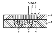
- FIGS. 5A, 5B, and 5C are diagrams for explaining a welding pattern of a nickel-plated copper terminal of a cell and an aluminum bus bar in the second embodiment.
- connection part of the aluminum bus-bar 2 is polymerized and arrange
- a gap 9 between the aluminum bus bar 2 and the nickel-plated copper terminal 1 is made by a jig that presses the surface portion of the aluminum bus bar 2 not irradiated with the laser downward from above in FIG. 5B. As small as possible.
- the first laser beam 6c moves away from the aluminum bus bar 2 so that the aluminum melted by the first laser beam 6c solidifies, and aluminum in a portion near the interface of the nickel plated copper terminal 1 from the surface of the aluminum bus bar 2
- the bus bar 2 becomes the first solidified portion 3 of aluminum.
- the third solidified portion 4 of the alloy having a shallow depth is formed.
- FIG. 5A a second laser beam 6d having the same output as the first laser beam 6c along the straight track 11 parallel to the straight track 10 and shown in FIG. 5A next to the track 10 is shown in FIG. 5A.
- the second laser beam 6d scans at a speed that is at least 25%, preferably 50%, slower than the first laser beam 6c.
- the second laser beam 6d moves away from the aluminum bus bar 2 so that the aluminum melted by the second laser beam 6d solidifies, and the aluminum bus bar 2 in a portion near the interface of the nickel plated copper terminal 1 from the surface of the aluminum bus bar 2 Becomes the first solidified portion 3 of aluminum.
- the second laser light 6d is mixed to a deeper position, and the second laser light 6 d is moved away from the aluminum bus bar 2 to form the second solidified portion 5 of the deep alloy.
- the distance between the track 10 of the first laser beam 6 c and the track 11 of the second laser beam 6 d is such that the first solidified portions 3 of the aluminum bus bar 2 stick together and become one mass.
- the inner third coagulating portion 4 and the second coagulating portion 5 are located apart from each other.
- the outputs of the first laser beam 6c and the second laser beam 6d are 1600 W.
- the scanning speed of the first laser beam 6c is 800 mm / sec
- the scanning speed of the second laser beam 6d is 500 mm / sec.
- the distance between the first laser beam 6c and the second laser beam 6d is 0.25 mm.
- the thickness of the aluminum bus bar 2 is 1 mm.
- the melted portion melted by the first laser beam 6 c is quickly cooled and becomes the third solidified portion 4.
- the third solidification unit 4 still maintains a high temperature. Therefore, the molten metal portion melted by the second laser beam 6 d becomes higher than the melting temperature when the second laser beam 6 d is scanned only once due to the heat conduction from the third solidification portion 4.
- the temperature of the molten metal portion melted by the second laser beam 6d is at a distance from the third solidification portion 4, and unmelted copper is present between the third solidification portion 4 and the molten metal portion. Therefore, the amount of heat conduction to the molten metal part is attenuated by the heat conduction in the direction parallel to the laser scanning direction in this part, and the temperature rise is considerably suppressed.
- FIG. 5B similarly to the second laser beam 6d, scanning is performed while irradiating the third laser beam 6d along a track adjacent to the track already scanned, and similarly to the portion near the surface of the aluminum bus bar 2
- the first solidified portion 3 of aluminum is formed, and the second solidified portion 5 of the deep alloy is formed in the vicinity of the interface between the aluminum bus bar 2 and the nickel-plated copper terminal 1.
- the third coagulation shown in FIG. 5B The welding structure is such that the portion 4 or the second solidified portion 5 is separated from each other.
- the third solidified portion 4 of the alloy having a shallow depth has a short heating time and a low melting temperature. Therefore, when the first laser beam 6c moves away from the melting portion, the melting portion solidifies quickly. For this reason, the melting portion has a short melting time, does not become an intermetallic compound, and becomes a normal alloy (that is, a state in which a large number of lattice defects exist). In order to reduce the strength of the weld.
- the second solidification part 5 having a slow scanning speed of the second to n-th laser light 6 d has a slow scanning speed and a long heating time as compared to the third solidification part 4 and a high melting temperature. Even if the 2nd to n-th laser light 6 d moves away from the respective melting parts, the time to solidify is sufficiently long, and a large amount of intermetallic compounds having almost no lattice defects are formed.
- This intermetallic compound is characterized in that the lattice is not easily displaced due to the tensile stress and the stress can not be relieved, so separation between the lattices occurs with a lower tensile force than the third solidified portion 4 and the tensile strength is low. Have.
- the third solidified portion 4 maintains high strength even when the gap 9 of the aluminum bus bar 2 is hardly present on the nickel-plated copper terminal 1. be able to. Further, when the gap 9 of the aluminum bus bar 2 is generated on the nickel plated copper terminal 1 as shown in FIG. 5C due to the production variation, the third solidified portion 4 having a shallow depth is almost melted with the copper terminal 1 There is almost no tensile strength due to the third solidified portion 4.
- each second solidified portion 5 has a low tensile strength, but a large tensile force as a whole It is possible to form a welded joint with strength.
- at least one or more locations of the second solidified portion 5 and the third solidified portion 4 are formed.
- the second solidified portion 5 has a deep depth from the overlapping position by the irradiation of the second laser beam 6d having a large energy to be irradiated, with respect to the cross section in the direction perpendicular to the advancing direction of welding.
- the third solidified portion 4 has a shallow depth from the overlapping position by the irradiation of the first laser beam 6c having a small energy to be irradiated, with respect to the cross section in the direction perpendicular to the advancing direction of welding.
- the deep second solidified portion 5 also be provided at two or more places.
- the irradiation pattern of the laser beam seen from the upper surface at that time is shown to FIG. 6A. 6B and 6C, the third solidified portion 4 having a shallow depth is located at both ends, but the position of the shallow third solidified portion 4 may be anywhere, and three or more third solidified portions 4 are provided. It does not matter. 6A, 6B and 6C will be described in detail in Example 5.
- FIG. 7A, 7B, and 7C show an example in which the third solidified portion 4 having a shallow depth and the second solidified portion 5 having a deep depth are alternately arranged.
- FIG. 7B shows the case where there is no gap 9 and
- FIG. 7C shows the case where there is a gap 9.
- the irradiation pattern of the laser beam seen from the upper surface at that time is shown to FIG. 7A.
- the tensile stress is a welded portion It is most preferable because it is uniformly dispersed throughout, so that resistance to fracture is improved and stabilized without stress concentration. 7A, 7B and 7C will be described in detail in a sixth embodiment.
- a 1 mm-thick aluminum bus bar 2 is stacked on a 2 mm-thick copper terminal 1 plated with nickel and having a plating thickness of 6 ⁇ m.
- the gap 9 between the copper terminal 1 and the aluminum bus bar 2 is disposed so as not to open as much as possible by a jig (not shown) pressed downward from above the aluminum bus bar 2.
- the first laser beam 6c with an output of 1600 W oscillated from the fiber laser is irradiated at a speed of 800 mm / s and a distance of 10 mm along the track 10 for forming the third solidified portion 4 which is shallow from the surface of the aluminum bus bar 2 While scanning.
- the second laser beam 6d of 1600 W is moved at a speed of 500 mm / s along the track 11 for forming the second solidified portion 5 deep with a lateral displacement of 0.25 mm with respect to the track 10 Scan a distance of 10 mm.
- the laser beam 6d is scanned a total of six times in the same manner as the second laser beam 6d.
- the tensile strength peel strength
- the aluminum bus bar 2 is disposed on the nickel-plated copper terminal 1 so that the gap 9 is opened by 0.1 mm, and welding is performed in the same manner as described above.
- the tensile strength at this time is 212 N, 210 N, and 200 N in three samples prepared in the same manner, and even when the gap 9 is 0.1 mm, the very high tensile strength exceeding 200 N is exhibited.
- the laser irradiation pattern is changed to perform the similar welding so that the third solidified portion 4 having a shallow depth is positioned from the rightmost position in FIG. 5B to the fourth position from the right.
- a tensile strength exceeding 150 N was similarly obtained both in the case where the gap 9 was not present and in the case where the gap 9 was 0.1 mm.
- the laser irradiation pattern is changed and the same welding is performed so that the position of the third solidified portion 4 with a shallow depth is at the leftmost position.
- a tensile strength exceeding 150 N was similarly obtained both in the case where the gap 9 was not present and in the case where the gap 9 was 0.1 mm.
- the welding portion has the welded structure in which the third solidified portion 4 having at least one shallow depth and the second solidified portion 5 having a plurality of deep depths are formed.
- stable welding could be realized.
- the conditions such as the laser output, the welding speed, and the scanning interval depend on the material of the metal member to be welded, the surface condition, the plate thickness, or the total heat capacity including the jig, and thus are not limited to the above conditions.
- a fiber laser is used as the laser oscillator, but the same effect can be obtained by using another laser such as a disk laser, a YAG laser, a CO 2 laser, or a semiconductor laser capable of obtaining high output. .
- the fourth embodiment is the same as the fourth embodiment except for the arrangement of the trajectory 10 of the first laser beam 6c forming the third solidified portion 4 having a shallow depth and the trajectory 11 of the second laser beam 6d forming the second solidified portion 5 having a deep depth. Do welding in the same way.
- the aluminum bus bar 2 is disposed on the nickel-plated copper terminal 1 such that there is no gap 9 therebetween.
- the laser irradiation pattern as shown in FIG. 6A is changed so that the third solidified portion 4 having a shallow depth is formed at two positions, the rightmost position and the leftmost position of the joint, and welding similarly I do.
- 207N, 228N, and 210N were obtained with three samples prepared in the same manner, and a very high bonding strength exceeding 200N was obtained in each case.
- the third coagulation part 4 having a shallow depth is changed to a laser irradiation pattern from the rightmost position and the leftmost position in FIG. 6B so as to be the rightmost position and the fourth position from the right.
- high tensile strength of 200 N or more was obtained both in the case where there is no gap 9 and in the case where the gap 9 is 0.1 mm.
- the laser irradiation pattern is changed to perform the same welding so that the third solidified portion 4 having a shallow depth is the fourth position from the right and the leftmost position.
- high tensile strength of 200 N or more was similarly obtained in both cases where there is no gap 9 and in the case where the gap 9 is 0.1 mm.
- the third coagulation part 4 having a shallow depth is located at the rightmost position and the leftmost position, the rightmost position and the fourth position from the right, and the fourth position from the right and the leftmost. Only three arrangements of the position of were described. However, the same effect can be obtained by arranging at any place.
- the fourth embodiment is the same as the fourth embodiment except for the arrangement of the trajectory 10 of the first laser beam 6c forming the third solidified portion 4 having a shallow depth and the trajectory 11 of the second laser beam 6d forming the second solidified portion 5 having a deep depth. Welding was performed similarly.
- the aluminum bus bar 2 is disposed on the nickel-plated copper terminal 1 so that there is no gap 9.
- the third solidified portion 4 having a shallow depth is set to the rightmost position, and a laser irradiation pattern is formed such that the second solidified portion 5 having a deep depth is formed at the position on the left side.
- the third solidified portion 4 having a shallow depth is formed at the left position, and the second solidified portion 5 having a deep depth is formed at the left position, similarly to the laser irradiation pattern shown in FIG. 7A.
- Do welding thus, a welded structure is formed in which the third solidified portion 4 having a shallow depth and the second solidified portion 5 having a deep depth are alternately arranged.
- the aluminum bus bar 2 is disposed on the nickel-plated copper terminal 1 so that the gap 9 is 0.1 mm, and then the same welding is performed.
- the tensile strength at this time was measured, 207N, 236N, and 222N were obtained with three samples prepared in the same manner, and a very high bonding strength exceeding 200N was obtained in each case.
- the welding portion in which the third solidified portion having a shallow depth and the second solidified portion having a deep depth are alternately arranged, the welding can be further stabilized with or without the gap 9. Can be realized.
- the shallow third solidified portion 4 is disposed at the rightmost position, and then the deep second solidified portion 4 is sequentially formed.
- the same effect can be obtained even if the deep second coagulated portion 5 is first formed and then the shallow third coagulated portion 4 is sequentially formed.
- Example 7 The relationship between the ratio between the depth of the third solidified portion 4 having a shallow depth and the depth of the second solidified portion 5 having a deep depth and the bond strength is examined.
- tensile strength peel strength
- a nickel-plated copper terminal 1 was fixed with a vise, and the unwelded portion of the aluminum bus bar 2 was pulled upward at a constant speed by a clamp attached to a force gauge fixed to a measurement stand (tensile tester). The indicated value of the force gauge at that time is taken as the tensile strength.
- the third solidified portion 4 having a shallow depth is set to the rightmost position, and the depth is set to the next position.
- the third solidified portion 4 having a shallow depth is formed at the next position.
- the third solidified portion 4 and the second solidified portion 5 are formed alternately.
- the output of the first laser beam 6c for forming the third solidified portion 4 having a shallow depth is set to 1600 W, and the scanning speed of the laser beam is set to 800 mm / s.
- the output of the second laser beam 6d for forming the deep second coagulation part 5 is the same 1600 W as the first laser beam 6c, and the scanning speed is 700 mm / s, 600 mm / s, 500 mm / s, 400 mm / s. , 300 mm / s, 200 mm / s, 100 mm / s.
- the aluminum bus bar 2 was disposed on the nickel-plated copper terminal 1 so that the gap 9 was 0.1 mm, and then the same welding was performed.
- the depth was taken as the deepest depth about each coagulation
- the scanning speed is 100 mm / s, and there is no gap, the tensile strength is high and there is no problem.
- the evaluation was evaluated as x (that is, not possible).
- the scanning speed of the laser beam 6d for forming the second solidified portion 5 having a deep depth is 700 mm / s, and when there is a gap 9, the depth is as shallow as 0 ⁇ m to 8 ⁇ m and the bonding strength is 0 N And low.
- the scanning speed is reduced to 600 mm / s, the depth is 10 ⁇ m to 35 ⁇ m in the case of a gap, the depth is 38 ⁇ m to 57 ⁇ m in the case of no gap, and the depth is deeper in both cases.
- the bonding strength is improved to 205 N and 186 N, respectively.
- the effect of further improving the bonding strength at a depth (length) of 10 ⁇ m or more of a shallow melted part (corresponding to the third solidified part 4 after solidification) It could be confirmed.
- the depth of the shallow melted portion (corresponding to the third solidified portion 4 after solidification) is 84 ⁇ m or less because the formation of the intermetallic compound can be suppressed and high bonding strength can be maintained.
- the seventh embodiment an example of setting of the laser output and the scanning speed is shown.
- these values vary depending on the plating thickness, the thickness of the terminal, or the thickness of the bus bar, and also depend on the material of the metal member to be welded, the surface condition, the plate thickness, or the total heat capacity including the jig. Therefore, it is not limited to this value.
- Example 8 The relationship between the depth of the third solidified part 4 having a shallow depth and the distance between the solidified parts of the second solidified part 5 having a deep depth and the joint strength is examined.
- the welding and bonding strength evaluation methods are the same as in Example 4 except for the distance between the tracks.
- the distance between the tracks is increased by 0.050 mm, 0.075 mm, 0.100 mm, and 0.025 mm each, and the same welding is performed to 0.300 mm.
- the distance between the solidified portions is the shortest distance among the respective solidified portions.
- the closest distance between the solidified portions is less than 10 ⁇ m and the tensile strength is less than 150 N in both of no gap and 0.1 mm of gap 9 It is a low value.
- the closest distance between the solidified portions is 10 ⁇ m or more, and the tensile strength also exhibits a high value of 150 N or more.
- the tensile strength is a value less than 150N.
- the second solidification part 5 and the third solidification part 4 it is better for the second solidification part 5 and the third solidification part 4 to be away from each other up to the first solidification part 3 respectively.
- the distance between the second solidified portion 5 and the third solidified portion 4 is 10 ⁇ m or more, heat is conducted by heat conduction in parallel with the scanning direction in the unmelted metal portion, and the temperature rise of the melted portion Is preferable because it can suppress the
- the distance between the second solidified portion 5 and the third solidified portion 4 is preferably 111 ⁇ m or less from the viewpoint of preventing the solidified portion from being separated too much to hold the function as one large welded portion.
- the optimum values of these values differ depending on the plating thickness, the thickness of the terminal or the thickness of the bus bar, and welding Depend on the total heat capacity including the material, surface condition, plate thickness, or jig of the metal member to be used. Therefore, it is not limited to this value.
- the technology according to the present embodiment can be applied to welding of aluminum, nickel, iron, copper, stainless steel, or an alloy thereof.
- applicable stainless steels include austenitic, ferritic, martensitic, austenitic and ferritic (two-phase systems).
- the welding structure and welding method of metal members according to the present disclosure it is possible to weld dissimilar metals of aluminum and nickel-plated copper with high quality and low cost. Therefore, a battery system can be provided at low cost. Furthermore, the welded structure of the metal member according to the present disclosure can be applied to a vehicle-mounted battery or a stationary storage system that requires high output.
Landscapes
- Chemical & Material Sciences (AREA)
- Chemical Kinetics & Catalysis (AREA)
- Electrochemistry (AREA)
- General Chemical & Material Sciences (AREA)
- Physics & Mathematics (AREA)
- Optics & Photonics (AREA)
- Engineering & Computer Science (AREA)
- Plasma & Fusion (AREA)
- Mechanical Engineering (AREA)
- Inorganic Chemistry (AREA)
- Laser Beam Processing (AREA)
- Connection Of Batteries Or Terminals (AREA)
Abstract
金属部材の溶接構造は、金属部材を含む第1部材と、金属部材を含む第2部材と、第1凝固部と、第2凝固部と、第3凝固部と、を有する。第1凝固部は、第1部材の第1面から第2面に亘って存在する。第2凝固部は、第1端が第2部材内に存在し、第2端が第1凝固部と接続している。第3凝固部は、第1端が第2部材内に存在し、第2端が第1凝固部と接続している。第3凝固部は、第2凝固部より短い。第2凝固部および第3凝固部は、第2部材内において、互いに離間している。
Description
本開示は、第1部材を第2部材の上に重ね合わせて溶接する金属部材の溶接構造および溶接方法に関する。
バッテリシステムは、複数の電池セルを金属板のバスバーで接続している。バスバーは、バッテリシステムを構成する電池セルの電極端子にレーザ溶接して接続される。この接続構造は、電池セルの電極端子の平らな部分の上にバスバーを配置させ、バスバーの表面側からレーザ光を照射して、電極端子とバスバーとの両方を溶融して接続している。
電池には正極と負極があり、通常、正極側にはアルミニウムの端子が使用され、負極側にはニッケルめっきされた銅端子が使用されている。バスバーは、隣接する電池セルを直列又は並列に接続するので、1つのバスバーには、少なくとも2つの電池セルの電極端子が接続される。
バスバーに、クラッド材と呼ばれるアルミニウムと銅との結合部材を用いた場合、正極側のアルミニウム端子はクラッド材のアルミニウム側と溶接し、負極側の銅端子はクラッド材の銅側と溶接すれば良いので、それぞれ同種金属同士の溶接であり、特に技術的に困難な点はない。
しかしながら、このクラッド材は、アルミニウムと銅との薄い板を接合部が重なるようにそれぞれ重ね合わせて、熱を加えながら圧力をかけて圧着するため、工程にかかる費用が高くまた直材費も高価なため、低コスト化ができない。
そこで、バスバーに安価なアルミニウムを用いることにより、安価で軽いバッテリシステムを生産することが可能となる。しかし、アルミニウムバスバーを用いる場合、正極側はアルミニウムバスバーとアルミニウム端子の同種材溶接で問題無いが、負極側はアルミニウムバスバーとニッケルめっきの銅端子との異種材溶接となり、安定して高品質な溶接を実現することが非常に困難となる。
異種材溶接は、異なる金属材料を共に溶融し、混ざり合った後に凝固させることにより溶接を行っている。アルミニウムと銅との異種材溶接については、その合金が十分に加熱されて、ある温度以上で一定の時間溶融していると、アルミニウムと銅との組成が一定比率の金属間化合物が形成される。この金属間化合物は、格子欠陥が少なく非常に硬い層であるが、応力を加えると脆く千切れてしまう。このため、単に溶融体積を増やせば高い接合強度が得られる訳ではなく、高い接合強度を安定して得ることが困難である。特に、バッテリシステムの製造において、アルミニウムバスバーとニッケルめっきの銅端子とを全てにおいて完全に隙間無く配置することは難しく、隙間がある程度あっても、あるいは隙間が無くても、常に、高い接合強度が得られる高品質な溶接を安定的に実現することは非常に困難である。
異種材溶接において、その強度対策の構造としては、高硬度層と低硬度層とを溶接の進行方向に交互に繰り返して積層してなる溶接構造が発明されている(特許文献1参照)。
特許文献1の方法を、図10A及び図10Bの断面図に示す。図10Bは、図10AのA-A線の断面図である。フェライト系ステンレス鋼または低炭素鋼の第1部材21と、マルテンサイト系ステンレス鋼または高炭素鋼の第2部材22と、を重ね合せ、第1部材21の表面にレーザ光を照射する。
斜線の領域で示している溶融凝固部は、図10Bに示すように、レーザ光の照射方向と直角方向の断面では、第1部材21の表面側から内部に向けて徐々に幅が狭くなる逆三角形の断面構造を有している。
また、溶融凝固部は、その表面側に低硬度層23を、内部側には高硬度層24を有している。かつ、高硬度層24は、第1層25と、それよりも硬度が低い第2層26と、を溶接進行方向に交互に繰返し積層してなる。
この溶接構造の作製方法として、第1部材21の表面にレーザ光をパルス的に照射する。まず、第1パルスのレーザ光により第1部材21及び第2部材22を溶融させてなる第1溶融部を形成する。
次いで、第1溶融部の凝固の成長がレーザ光軸の移動距離の1/2に達した時点において、位置を少しずらして、第2パルスのレーザ光の照射を開始する。これにより、第1溶融部と一部重なるように第2溶融部が形成される。この後、順次、同様に、第3以降のパルスのレーザ光を所定のインターバルでオン・オフしながら照射することにより、溶接構造を形成する。
この溶接構造の特徴として、前述のように溶接の進行方向と直角方向の断面(図10B)は逆三角形の構造となっており、進行方向の断面(図10A)は進行方向に第1層25と第2層26とが繰返し積層している。第1層25と第2層26の溶融深さは、ほぼ同じである。
本開示の金属部材の溶接構造は、第1部材と、第2部材と、第1凝固部と、第2凝固部と、第3凝固部と、を有する。
第1部材は、第1面と、第1面の反対側の第2面とを有し、金属部材を含む。
第2部材は、第1部材の第2面に積層され、金属部材を含む。
第1凝固部は、第1部材の第1面から第2面に亘って存在する。
第2凝固部は、第1端が第2部材内に存在し、第2端が第1凝固部と接続している。
第3凝固部は、第1端が第2部材内に存在し、第2端が第1凝固部と接続している。
第3凝固部は、第2凝固部より短い。
第2凝固部および第3凝固部は、第2部材内において、互いに離間している。
また、本開示の金属部材の溶接方法は、金属部材を含む第1部材と、金属部材を含む第2部材との溶接方法である。
第1部材は、第1面と、第1面の反対側の第2面とを有する。
第2部材は、第1部材の第2面に積層される。
金属部材の溶接方法は、
第1レーザ光を第1軌道に沿って走査する第1走査と、
第1レーザ光より高出力又は低速度で第2レーザ光を第1軌道と異なる第2軌道に沿って走査する第2走査と、
を有する。
第1レーザ光を第1軌道に沿って走査する第1走査と、
第1レーザ光より高出力又は低速度で第2レーザ光を第1軌道と異なる第2軌道に沿って走査する第2走査と、
を有する。
第1走査と第2走査とを、少なくともそれぞれ1回ずつ交互に行う。
第1走査と第2走査とにより、第1部材の第1面から第2面に亘って第1部材の金属を溶融したのち凝固させて第1凝固部を形成する。
第1走査により、第1凝固部を形成するとき、第2部材の金属を溶融したのち凝固させて、第1端が第2部材内に存在し、第2端が第1凝固部と接続される第2凝固部を形成する。
第2走査により、第1凝固部を形成するとき、第2部材の金属を溶融したのち凝固させて、第1端が第2部材内に存在し、第2端が第1凝固部と接続される第3凝固部を形成する。
第1走査に続いで第2走査を行うとき、第1走査による第2部材の溶融部が互いに分離可能な距離まで移動した第2軌道で第2レーザ光による第2走査を行う。
しかしながら、特許文献1に示される従来技術の溶接構造は、第1層25と第2層26との溶接深度が同じであるため、工程のばらつきで発生する隙間に対して、弱い。隙間がほとんど無い場合には、一方の層が他方の層に深く溶け込んで溶融体積が増えるため、金属間化合物が多く形成されて接合強度が弱くなる。接合強度を高くするには、溶接深度を浅くして金属間化合物の生成を抑制する必要がある。しかし、溶接深度を浅くすると、隙間が発生した場合に、更に溶接深度が浅くなり、溶接強度が低下する。以下、本実施の形態について、図面を参照しながら説明する。説明の簡略化のため、実質的に同一の機能を有する構成要素を同一の参照符号で示す。
実施の形態1~2とそれぞれに対応する実施例の関係をまとめたものを、表1に示す。

以下に、各実施の形態について説明する。
(実施の形態1)
本実施の形態1において、第1部材の一例がアルミニウムを含む金属部材であり、第2部材の一例が銅を含む金属部材である。より具体的には、電池セルを接続するバスバーを第1部材の一例とし、セルの端子を第2部材の一例とする。第1部材と第2部材とは、合金を形成する金属同士であればよい。
本実施の形態1において、第1部材の一例がアルミニウムを含む金属部材であり、第2部材の一例が銅を含む金属部材である。より具体的には、電池セルを接続するバスバーを第1部材の一例とし、セルの端子を第2部材の一例とする。第1部材と第2部材とは、合金を形成する金属同士であればよい。
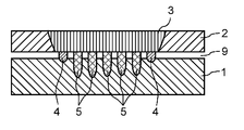
図1は、本実施の形態1における、セルのニッケルめっきの銅端子とアルミニウムバスバーとの溶接構造又は溶接構造体を説明する図である。図1Aは、アルミニウムバスバー側から溶接構造体を見た上面図である。図1Bは、図1AのA-A’の断面図である。
第2部材の一例であるニッケルめっきの銅端子1の上に、第1部材の一例であるアルミニウムバスバー2の接続部を重ね合せて配置する。この時、図1Bに図示していないが、アルミニウムバスバー2の、レーザを照射しない表面部分を、図1Bの上方より下方に向って押し当てる治具により、アルミニウムバスバー2とニッケルめっきの銅端子1との隙間がなるべく小さくなるようにする。
次に、第1走査として、任意の出力に設定された第1レーザ光6aを照射しながら、図1Aに示す直線の軌道7に沿って、図1Aの上方から下の方向へ、すなわち、図1Bの奥の方から手前側へ任意の速度で走査する。これにより、図1Bの右端のアルミニウムバスバー2の第1レーザ光6aが照射された近傍が溶融する。
その後、第1レーザ光6aがアルミニウムバスバー2から遠ざかることにより、第1レーザ光6aで溶融していたアルミニウムが凝固し、アルミニウムバスバー2の表面からニッケルめっきの銅端子1の界面に近い部分のアルミニウムバスバー2は、第1凝固部の一例である第1凝固部3となる。一方、アルミニウムバスバー2とニッケルめっきの銅端子1との界面付近からニッケルめっきの銅端子1の界面近傍が溶融した部分は、アルミニウムと、ニッケルと銅とが溶融した状態で混ざり合い、第1レーザ光6aがアルミニウムバスバー2から遠ざかることにより、深度(すなわち、長さ)が浅い合金の第3凝固部4となる。ここで、浅いとは、金属間化合物生成の影響を抑えるため、一例として5mm程度浅い場合を意味する。
次に、第2走査として、直線の軌道7と平行でかつ軌道7の隣の図1Aに示す直線の軌道8に沿って、軌道7の第1レーザ光6aよりも高出力である第2レーザ光6bを、第1レーザ光6aと同様に、図1Aの上方から下の方向へ、すなわち図1Bの奥の方から手前側へ走査する。なお、第2レーザ光6bの出力は、少なくとも第1レーザ光6aの105%以上とする。
その後、第2レーザ光6bがアルミニウムバスバー2から遠ざかることにより、第2レーザ光6bで溶融したアルミニウムが凝固し、アルミニウムバスバー2の表面からニッケルめっきの銅端子1の界面に近い部分のアルミニウムバスバー2は、アルミニウムの第1凝固部3となる。一方、アルミニウムバスバー2とニッケルめっきの銅端子1との界面付近からニッケルめっきの銅端子1の界面近傍が溶融した部分は、アルミニウムと、めっきである僅かなニッケルと銅とが溶融した状態で、第1レーザ光6aの出力よりも第2レーザ光6bの出力が高い分、より深くまで混ざり合い、第2レーザ光6bがアルミニウムバスバー2から遠ざかることにより、深度が深い合金の第2凝固部5となる。
このとき、第1レーザ光6aの軌道7と、第2レーザ光6bの軌道8との間隔は、アルミニウムバスバー2の第1凝固部3では互いにくっついて一塊となり、かつ、ニッケルめっき銅端子1の内部の第3凝固部4と第2凝固部5とでは互いに離れて位置するよう、調整されている。ここで、例えば、第1レーザ光6aの出力は1600W、第2レーザ光6bの出力は2000W、第3凝固部4と第2凝固部5との間隔は0.25mm、アルミニウムバスバーの厚さ1mmである。第1レーザ光6aが軌道7を走査した後、第1レーザ光6aで溶融された溶融部は速やかに冷却されて第3凝固部4となるが、次の第2レーザ光6bが軌道8を走査するときには、第3凝固部4では、まだ高い温度を保っている。従って、第2レーザ光6bによって溶融される溶融金属部は、第3凝固部4からの熱伝導により、第2レーザ光6bを1回のみ走査したときの溶融温度よりも高くなる。しかしながら、第2レーザ光6bによって溶融される溶融金属部の温度は、第3凝固部4から距離が離れており、且つ第3凝固部4と溶融金属部との間に未溶融の銅が存在するため、この部分でのレーザ走査方向と平行な方向への熱伝導により、溶融金属部への熱伝導量が減衰し、温度上昇がかなり抑制される。
続けて、第3走査として、図1Bにおいて、第2レーザ光6bと同様に、既に走査した軌道8に隣接する軌道8沿いに第3レーザ光6bを照射しながら走査する。これにより、アルミニウムバスバー2の表面に近い部分には、アルミニウムの第1凝固部3を形成し、アルミニウムバスバー2とニッケルめっきの銅端子1との界面近傍には、深度が深い合金の第2凝固部5を形成する。
その後、第4以降の走査として、順次、レーザ光をずらして同様に第4~第n(nは5以上の整数、)のレーザ光6bで軌道8と平行な軌道8を走査することにより、図1Bに示す第3凝固部4あるいは第2凝固部5が互いに離れている溶接構造となる。ここで、第1レーザ光6aによる第1走査に続いで第2レーザ光6bによる第2走査を行うとき、第1走査によるニッケルめっきの銅端子1の溶融部が互いに分離可能な距離まで移動した第2軌道8で、第2レーザ光6bによる第2走査を行う。同様に、第2レーザ光6bによる第2走査に続いで第3レーザ光6bによる第3走査を行うとき、第2走査によるニッケルめっきの銅端子1の溶融部が互いに分離可能な距離まで移動した第3軌道8で、第3レーザ光6bによる第3走査を行う。以後、同様である。
図1Bにおいて、深度が浅い合金の第3凝固部4は、第1レーザ光6aの出力が第2レーザ光6bの出力よりも低いため、溶融時の温度が低い。そのため、第1レーザ光6aが移動して溶融部から離れると、その溶融部は速やかに凝固する。このため、その溶融部は、溶融時間が短く、金属間化合物が生成され難く、通常の合金(すなわち、格子欠陥が多く存在する固溶体)が主の成分となり、引張り応力に対して格子のズレが簡単に起こり、応力を緩和するため、強度の高い溶接となる。
一方、第2~第nレーザ光6bの出力が高い第2凝固部5は、第3凝固部4と比較して出力が高いため、溶融時の温度が高い。このため、第2~第nレーザ光6bが移動してそれぞれの溶融部から離れてから凝固するまでに、時間が十分に長く、格子欠陥の殆ど無い金属間化合物が多く形成される。すなわち、第2凝固部5には、第3凝固部4と比べて、より多くの金属間化合物が存在する。これに対して、隣接する第2凝固部5が互いに離間するように形成することで、溶融部から未溶融部を介して熱を開放させることができるため、凝固部を密着させる場合に比べて金属間化合物の発生を抑制できる。上記の構成にすれば、図1Bにおけるニッケルめっき銅端子1内の第3凝固部4、あるいは第2凝固部5が互いに離れて間が空いて、接合部が形成されている。このため、第3凝固部4と第2凝固部5とのそれぞれが第1レーザ光6a,第2レーザ光6bによって溶融したのち凝固する際、直前の軌道7,8の蓄熱の影響を受け難く、温度上昇を抑えることができる。このため、各凝固部で金属間化合物が多く生成されることを抑制でき、接合強度の高い異種材溶接が可能となる。なお、第2凝固部5の断面を占める金属間化合物の面積割合は、0%より多く10%以下であることが望ましい。
なお、複数の第2凝固部5および複数の第3凝固部4は、同一の第1凝固部3に接続されている。
実施の形態1の構成によれば、図1Bのように、ニッケルめっきの銅端子1の上にアルミニウムバスバー2の隙間9が殆ど無い場合でも、第3凝固部4によって高い強度を維持することができる。また、生産のばらつきにより図2のようにニッケルめっきの銅端子1の上にアルミニウムバスバー2の隙間9が発生した場合には、深度が浅い第3凝固部4は殆ど銅端子1と溶融しておらず、第3凝固部4による引張り強度は殆ど無い。しかしながら、この場合は、深度の深い複数個の第2凝固部5が広い面積で銅端子1と溶融しており、一つ一つの第2凝固部5は引張り強度が低いが、全体として大きな引張り強度を持つ溶接構造の接合部が形成できる。このように、本開示の溶接構造は、溶接の進行方向と直角方向の断面に対して、深い第2凝固部5と、第3凝固部4とをそれぞれ少なくとも1箇所以上有している。第2凝固部5は、照射するエネルギが大きな第2レーザ光6bの照射により、重ね合わせ位置からの深度が深い。第3凝固部4は、照射するエネルギが小さな第1レーザ光6aの照射により、重ね合わせ位置からの深度が浅い。これより、生産のばらつきによりニッケルめっきの銅端子1の上にアルミニウムバスバー2の隙間9が殆ど無い場合でも、あるいは大きな隙間9が発生した場合でも、接合強度が高い安定した溶接を安価な押さえ治具を用いて作製できる。
深度の浅い第3凝固部4が1箇所でもあれば、上記のように隙間9が殆ど無い場合において、接合強度を維持する効果を持つ。しかし、深度の浅い第3凝固部4は、2箇所以上ある方が、応力が一箇所に集中せず分散されるため、好ましい。その場合、隙間9がある場合と同じ理由で、深度の深い第2凝固部5も、2箇所以上ある方が好ましい。その一例として、深度の深い第2凝固部5が中央に5箇所あり、且つ、深度の浅い第3凝固部4が両端に2箇所ある場合を図3A、図3Bに示す。図3Aは隙間9が無い場合、図3Bは隙間9がある場合を示している。なお、図3A及び図3Bでは、両端に深度の浅い第3凝固部4があるが、第3凝固部4の位置はこれに限らず、また第3凝固部4が3箇所以上であっても構わない。
第3凝固部4と第2凝固部5とが交互に配置されている場合を図4A、図4Bに示す。図4Aは隙間9が無い場合を示し、図4Bは隙間9がある場合を示している。レーザ光6a,6bの走査方向と交差する方向(例えば直交する方向)沿いに、深度の浅い第3凝固部4と深度の深い第2凝固部5とが交互に配置されている。そして、第3凝固部4と第2凝固部5の数が同じか、差が±1個である場合では、引張りの応力が溶接部全体に均等に分散されるため、応力集中せずに、破壊に対する耐性が向上して安定するため、好ましい。
(実施例1)
実施の形態1おいて、以下の具体的な実施例について説明する。図1Bにおいて、めっき厚6μmニッケルめっきを施した厚み2mmの銅端子1の上に、厚み1mmのアルミニウムバスバー2を重ねる。そして、アルミニウムバスバー2の上方から下方に向けて押し当てる治具(図示せず)により、銅端子1とアルミニウムバスバー2との間の隙間9がなるべく開かないように配置する。アルミニウムバスバー2の表面から深度が浅い第3凝固部4を形成するための軌道7に沿って、ファイバーレーザから発振した出力1600Wの第1レーザ光6aを、800mm/sの速度で10mmの距離を照射しながら走査する。
実施の形態1おいて、以下の具体的な実施例について説明する。図1Bにおいて、めっき厚6μmニッケルめっきを施した厚み2mmの銅端子1の上に、厚み1mmのアルミニウムバスバー2を重ねる。そして、アルミニウムバスバー2の上方から下方に向けて押し当てる治具(図示せず)により、銅端子1とアルミニウムバスバー2との間の隙間9がなるべく開かないように配置する。アルミニウムバスバー2の表面から深度が浅い第3凝固部4を形成するための軌道7に沿って、ファイバーレーザから発振した出力1600Wの第1レーザ光6aを、800mm/sの速度で10mmの距離を照射しながら走査する。
次に、軌道7に対して0.25mmだけ横にずらして、深度が深い第2凝固部5を形成するための軌道8に沿って、2000Wの第2レーザ光6bを、第1レーザ光6aと同様に800mm/sの速度で10mmの距離を走査する。
その後、順次、0.25mmずつずらしながら、第2レーザ光6bと同様に、レーザ光6bを計6回走査する。このときの図1Bの上方への引張り強度(剥離強度)を測定したところ、同様に作製した3つのサンプルで、202N、157N、168Nであり、何れも150Nを越える高い引張り強度を示した。
次に、図2に示すように、ニッケルめっきの銅端子1の上にアルミニウムバスバー2を隙間9が0.1mm開くように配置し、上記と同様に溶接を行う。このときの引張り強度は、同様に作製した3つのサンプルで、198N、207N、232Nであり、隙間9が0.1mmの場合でも、150Nを越える高い引張り強度を示した。
また、深度が浅い第3凝固部4を、図1Bの最も右側の位置から、右側から4番目の位置になるように、レーザ照射パターンを変更して、同様の溶接を行った。その結果、隙間9が無い場合と隙間9が0.1mmの場合との両方において、同様に150Nを越える引張り強度が得られた。
更に、深度が浅い第3凝固部4の位置が最も左側の位置になるように、レーザ照射パターンを変更して同様な溶接を行った。その結果、隙間9が無い場合と隙間9が0.1mmの場合との両方において、同様に150Nを越える引張り強度が得られた。
このように、接合部を、少なくとも1箇所の深度が浅い第3凝固部4と、複数の深度が深い第2凝固部5とを形成する溶接構造とすることにより、隙間9があっても無くても、安定した溶接が実現できる。
なお、本実施例1では、めっき厚、端子の厚み、及びバスバーの厚みの一例を示した。しかし、本開示の内容は、この値に限らない。また、レーザ出力、溶接速度、又は走査間隔等の条件は、溶接する金属部材の材料、表面状態、板厚、又は治具を含めた総熱容量に依存するため、上記の条件に限らない。
また、本実施例1では、深度の浅い第3凝固部4を、最も右側の位置、右側から4番目の位置、及び最も左側の位置の3箇所についてのみ説明した。しかし、何れの箇所に配置しても同様の効果が得られる。
本実施例1では、レーザ発振器としてファイバーレーザを用いたが、高出力が得られるディスクレーザ、YAGレーザ、CO2レーザ、又は半導体レーザ等の他のレーザを用いても、同様の効果が得られる。
本実施例1では、ニッケルめっき銅端子とアルミニウムバスバーとの事例について記載した。しかし、合金を形成する金属同士の組合せであれば、その他の金属の組合せでも同様の効果が得られる。
(実施例2)
深度が浅い第3凝固部4を形成する第1レーザ光6aの軌道7と、深度が深い第2凝固部5を形成する第2レーザ光6bの軌道8との配置以外は、実施例1と同様に溶接を行った。
深度が浅い第3凝固部4を形成する第1レーザ光6aの軌道7と、深度が深い第2凝固部5を形成する第2レーザ光6bの軌道8との配置以外は、実施例1と同様に溶接を行った。
図3Aに示すように、ニッケルめっきの銅端子1の上にアルミニウムバスバー2を隙間9が無いように配置する。その後、深度が浅い第3凝固部4が、接合部の最も右側の位置と、最も左側の位置との2箇所に形成されるようなレーザ照射パターンに変更し、同様に溶接を行る。このときの引張り強度(言い換えれば接合強度)を測定したところ、同様に作製した3つのサンプルで、170N、196N、173Nとなり、何れも150Nを越える高い接合強度が得られた。
次に、図3Bに示すように、ニッケルめっきの銅端子1の上にアルミニウムバスバー2を隙間9が0.1mmとなるように配置した後、同様の溶接を行う。このときの引張り強度を測定したところ、同様に作製した3つのサンプルで、221N、190N、199Nとなり、何れも150Nを越える高い接合強度が得られた。
次に、深度が浅い第3凝固部4を、図3Aの最も右側の位置と最も左側の位置とから、最も右側の位置と右側から4番目の位置とになるようにレーザ照射パターンを変更して、同様の溶接を行った。その結果、隙間9が無い場合と隙間9が0.1mmの場合との両方において、150から230Nの間の高い引張り強度が得られた。
更に、深度が浅い第3凝固部4を、右側から4番目の位置と最も左側の位置とになるようにレーザ照射パターンを変更して同様の溶接を行った。その結果、隙間9が無い場合と隙間9が0.1mmの場合との両方において、同様に150から230Nの間の高い引張り強度が得られた。
このように、接合部を、2箇所の深度が浅い第3凝固部4と、それ以外の複数個所の深度が深い第2凝固部5とする溶接構造とすることにより、隙間9があっても無くても、より安定した溶接が実現できる。
なお、本実施例2では、深度の浅い第3凝固部4を、最も右側の位置と最も左側の位置、最も右側の位置と右側から4番目の位置、及び右側から4番目の位置と最も左側の位置の3つの配置についてのみ説明した。しかし、第3凝固部4を、任意の箇所に配置しても同様の効果が得られる。
(実施例3)
深度が浅い第3凝固部4を形成する第1レーザ光6aの軌道7と、深度が深い第2凝固部5を形成する第2レーザ光6bの軌道8との配置以外は、実施例1と同様に溶接を行う。
深度が浅い第3凝固部4を形成する第1レーザ光6aの軌道7と、深度が深い第2凝固部5を形成する第2レーザ光6bの軌道8との配置以外は、実施例1と同様に溶接を行う。
図4Aに示すように、ニッケルめっきの銅端子1の上にアルミニウムバスバー2を隙間9が無いように配置する。その後、レーザ光6a,6bの走査方向と交差する方向(例えば直交する方向)沿いに、深度が浅い第3凝固部4が最も右側の位置に形成され、その左側の位置に深度が深い第2凝固部5が形成されるようにする。更に、その左側の位置に深度が浅い第3凝固部4が形成され、その左側の位置に深度が深い第2凝固部5が形成されるようにする。このように、深度が浅い第3凝固部4と、深度が深い第2凝固部5とが交互に配置される溶接構造とするレーザ照射パターンで、同様に溶接を行った。このときの引張り強度を測定したところ、同様に作製した3つのサンプルで、211N、201N、233Nとなり、何れも150Nを越える高い接合強度が得られた。
次に、図4Bに示すように、ニッケルめっきの銅端子1の上にアルミニウムバスバー2を隙間9が0.1mmとなるように配置する。その後、同様の溶接を行う。このときの引張り強度を測定したところ、同様に作製した3つのサンプルで、198N、226N、201Nとなり、何れも150Nを越える高い接合強度が得られた。
このように、接合部を、深度が浅い第3凝固部4と深度が深い第2凝固部5とを交互に配置する溶接構造とすることにより、隙間9があっても無くても、更に安定した溶接が実現できる。
なお、本実施例3では、深度の浅い第3凝固部4を最も右側の位置に配置し、次いで深度の深い第2凝固部5を順次形成した。しかし、深度の深い第2凝固部5を先に形成し、その後、深度の浅い第3凝固部4を順次形成しても、同様の効果が得られる。
(比較例1)
深度の深い第2凝固部5は形成せずに、深度が浅い第3凝固部4のみを形成する以外は、実施例1と同様に溶接を行う。
深度の深い第2凝固部5は形成せずに、深度が浅い第3凝固部4のみを形成する以外は、実施例1と同様に溶接を行う。
図8Aに示すように、ニッケルめっきの銅端子1の上にアルミニウムバスバー2を隙間9が無いように配置する。その後、深度が浅い第3凝固部4のみを形成するようにレーザ照射パターンを変更し、同様に溶接を行う。このときの引張り強度を測定したところ、同様に作製した3つのサンプルで、224N、215N、231Nとなり、何れも200Nを越える非常に高い接合強度が得られた。
次に、図8Bに示すように、ニッケルめっきの銅端子1の上にアルミニウムバスバー2を隙間9が0.1mmとなるように配置した後、同様の溶接を行う。このときの引張り強度を測定したところ、同様に作製した3つのサンプルで、26N、52N、9Nとなり、何れも100N未満の低い接合強度であった。
深度が浅い第3凝固部4のみの溶接構造では、隙間9が無いときは、金属間化合物の生成が抑制されて応力に強い通常の合金層となるため、引張り応力を緩和することができて高い接合強度を得ることができる。一方、隙間9がある場合は、ニッケルめっきの銅端子1と合金を生成する溶融量が極端に少なくなり、接合強度が著しく低下してしまう。このように、隙間9を無くすことができれば高い接合強度が得られるが、実際の生産において安定して確実に隙間9を無くすことは困難なため、安定した生産を行うことができない。
(比較例2)
深度が浅い第3凝固部4を形成せずに、深度が深い第2凝固部5のみを形成する以外は、実施例1と同様に溶接を行う。
深度が浅い第3凝固部4を形成せずに、深度が深い第2凝固部5のみを形成する以外は、実施例1と同様に溶接を行う。
図9Aに示すように、ニッケルめっきの銅端子1の上にアルミニウムバスバー2を隙間9が無いように配置する。その後、深度が深い第2凝固部5のみを形成するようにレーザ照射パターンを変更し、同様に溶接を行う。このときの引張り強度を測定したところ、同様に作製した3つのサンプルで、103N、149N、144Nとなり、何れも150N未満の接合強度となった。
次に、図9Bに示すように、ニッケルめっきの銅端子1の上にアルミニウムバスバー2を隙間9が0.1mmとなるように配置する。その後、同様の溶接を行う。このときの引張り強度を測定したところ、同様に作製した3つのサンプルで、188N、204N、212Nとなり、何れも150N以上の高い接合強度が得られた。
深度が深い第2凝固部5のみの溶接構造では、隙間9が無いときは金属間化合物が大量に生成されて引張り応力を緩和することができない。そのため、比較例1の隙間9が無い状態と比較して、接合強度が低くなる。一方、隙間9がある場合においては、ニッケルめっきの銅端子1内に金属間化合物が大量に形成されるのが緩和される。そのため、隙間9が無い場合より、高い接合強度となる。このように、照射するレーザ光の出力を向上させれば、隙間9が無い場合も隙間9がある場合も、ある一定程度の接合強度は安定して得られる。しかし、狭い接合面積で高い接合強度を安定して得られることはできず、高い接合強度が必要なバスバー溶接においては、溶接面積を大きくする必要があり、低コストでの生産が困難となる。
以上のことから、実施例1、実施例2、および実施例3の溶接では、隙間9がある場合も隙間9が無い場合も、比較例と比べて、安定した溶接が可能であり、歩留りが高く低コストである溶接を実現できる。
(実施の形態2)
図5A、5B、5Cは、本実施の形態2における、セルのニッケルめっきの銅端子とアルミニウムバスバーとの溶接パターンを説明する図である。
図5A、5B、5Cは、本実施の形態2における、セルのニッケルめっきの銅端子とアルミニウムバスバーとの溶接パターンを説明する図である。
図5Bに示すように、ニッケルめっきの銅端子1の上にアルミニウムバスバー2の接続部を重合せて配置する。このとき、図示していないが、アルミニウムバスバー2のレーザを照射しない表面部分を、図5Bの上方より下方に向って押し当てる治具により、アルミニウムバスバー2とニッケルめっきの銅端子1との隙間9をなるべく小さくなるようにする。
次に、任意の出力に設定された第1レーザ光6cを照射しながら、図5Aに示す直線の軌道10に沿って図5Aの上方から下の方向へ、すなわち図5Bの奥の方から手前側へ任意の速度で走査する。これにより、アルミニウムバスバー2の第1レーザ光6cが照射された近傍が溶融する。
その後、第1レーザ光6cがアルミニウムバスバー2から遠ざかることにより、第1レーザ光6cで溶融していたアルミニウムが凝固し、アルミニウムバスバー2の表面からニッケルめっきの銅端子1の界面に近い部分のアルミニウムバスバー2は、アルミニウムの第1凝固部3となる。一方、アルミニウムバスバー2とニッケルめっきの銅端子1との界面付近からニッケルめっきの銅端子1の界面近傍が溶融した部分は、アルミニウムと、めっきである僅かなニッケルと、銅とが溶融した状態で混ざり合い。そして、第1レーザ光6cがアルミニウムバスバー2から遠ざかることにより、深度が浅い合金の第3凝固部4が形成される。
次に、直線の軌道10と平行で、かつ、軌道10の隣の図5Aに示す直線の軌道11に沿って、第1レーザ光6cと同じ出力である第2レーザ光6dを、図5Aの上方から下の方向へ、すなわち図5Bの奥の方から手前側へ走査する。ここで、第2レーザ光6dは、第1レーザ光6cと比較して少なくとも25%、好ましくは50%遅い速度で走査する。
その後、第2レーザ光6dがアルミニウムバスバー2から遠ざかることにより、第2レーザ光6dで溶融したアルミニウムが凝固し、アルミニウムバスバー2の表面からニッケルめっきの銅端子1の界面に近い部分のアルミニウムバスバー2は、アルミニウムの第1凝固部3となる。一方、アルミニウムバスバー2とニッケルめっきの銅端子1との界面付近からニッケルめっきの銅端子1の界面近傍が溶融した部分は、アルミニウムと、めっきである僅かなニッケルと、銅とが溶融した状態で、第1レーザ光6cの走査速度よりも第2レーザ光6dの走査速度が遅い分、溶融時間が長くなる。そのため、より深くまで混ざり合い、第2レーザ光6dがアルミニウムバスバー2から遠ざかることにより、深度が深い合金の第2凝固部5となる。
このとき、第1レーザ光6cの軌道10と、第2レーザ光6dの軌道11との間隔は、アルミニウムバスバー2の第1凝固部3は互いにくっついて一塊となり、かつ、ニッケルめっき銅端子1の内部の第3凝固部4と第2凝固部5とは互いに離れて位置している。ここで、例えば、第1レーザ光6c及び第2レーザ光6dの出力は1600Wである。第1レーザ光6cの走査速度は800mm/sec、第2レーザ光6dの走査速度は500mm/secである。第1レーザ光6cと第2レーザ光6dの間隔は0.25mmである。アルミニウムバスバー2の厚さは、1mmである。第1レーザ光6cが軌道10を走査した後、第1レーザ光6cで溶融された溶融部は速やかに冷却されて第3凝固部4となる。しかし、次の第2レーザ光6dが軌道11を走査するときには、第3凝固部4では、まだ高い温度を保っている。従って、第2レーザ光6dによって溶融される溶融金属部は、第3凝固部4からの熱伝導により、第2レーザ光6dを1回のみ走査したときの溶融温度よりも高くなる。しかしながら、第2レーザ光6dによって溶融される溶融金属部の温度は、第3凝固部4から距離が離れており、且つ第3凝固部4と溶融金属部との間に未溶融の銅が存在するため、この部分でのレーザ走査方向と平行な方向への熱伝導により、溶融金属部への熱伝導量が減衰し、温度上昇がかなり抑制される。
続けて、図5Bにおいて、第2レーザ光6dと同様に、既に走査した軌道に隣接する軌道沿いに第3レーザ光6dを照射しながら走査し、同様に、アルミニウムバスバー2の表面に近い部分には、アルミニウムの第1凝固部3を形成し、アルミニウムバスバー2とニッケルめっきの銅端子1との界面近傍には、深度が深い合金の第2凝固部5を形成する。その後、順次、レーザ光をずらして同様に第4~第n(nは5以上の整数、)のレーザ光6dで軌道11と平行な軌道8を走査することにより、図5Bに示す第3凝固部4あるいは第2凝固部5が互いに離れている溶接構造となる。
図5Bにおいて、深度が浅い合金の第3凝固部4は、第1レーザ光6cの走査速度が第2レーザ光6dの走査速度よりも速いため、加熱時間が短く、溶融時の温度が低い。そのため、第1レーザ光6cが移動して溶融部から離れると、その溶融部は速やかに凝固する。このため、その溶融部は、溶融時間が短く、金属間化合物とならず、通常の合金(すなわち、格子欠陥が多く存在する状態)となり、引張り応力に対して格子のズレが簡単に起こり、応力を緩和するため、強度の高い溶接となる。
一方、第2~第nレーザ光6dの走査速度が遅い第2凝固部5は、第3凝固部4と比較して走査速度が遅く加熱時間が長くなって溶融時の温度が高いため、第2~第nレーザ光6dが移動してそれぞれの溶融部から離れても、凝固するまでに時間が十分に長く、格子欠陥の殆ど無い金属間化合物が多く形成される。この金属間化合物は、引張り応力に対して格子のズレが起き難く、応力を緩和できないため、第3凝固部4よりも低い引張り力で格子間の剥離が発生し、引張り強度が低いという特徴を持つ。
上記の実施の形態2の構成によれば、図5Bのように、ニッケルめっきの銅端子1の上にアルミニウムバスバー2の隙間9が殆ど無い場合でも、第3凝固部4によって高い強度を維持することができる。また、生産のばらつきにより図5Cのようにニッケルめっきの銅端子1の上にアルミニウムバスバー2の隙間9が発生した場合には、深度が浅い第3凝固部4は殆ど銅端子1と溶融しておらず、第3凝固部4による引張り強度は殆ど無い。しかしながら、この場合は、深度の深い複数個の第2凝固部5が広い面積で銅端子1と溶融しており、一つ一つの第2凝固部5は引張り強度が低いが、全体として大きな引張り強度を持つ溶接構造の接合部を形成できる。このように、第2凝固部5と、第3凝固部4とをそれぞれ少なくとも1箇所以上形成する。ここで、第2凝固部5は、溶接の進行方向と直角方向の断面に対して、照射するエネルギが大きな第2レーザ光6dの照射による重ね合わせ位置からの深度が深い。また、第3凝固部4は、溶接の進行方向と直角方向の断面に対して、照射するエネルギが小さな第1レーザ光6cの照射による重ね合わせ位置からの深度が浅い。このような構成にすることにより、生産のばらつきによりニッケルめっきの銅端子1の上にアルミニウムバスバー2の隙間9が殆ど無い場合でも、あるいは大きな隙間9が発生した場合でも、どちらにおいても、接合強度が高い安定した溶接を、安価な押さえ治具を用いて作製できる。
また、深度が浅い第3凝固部4が1箇所でもあれば、上記のように隙間9が殆ど無い場合において、接合強度を維持する効果を持つ。しかし、深度の浅い第3凝固部4は2箇所以上ある方が、応力を一箇所に集中せず分散されるため、好ましい。その場合、隙間9がある場合と同じ理由で、深度の深い第2凝固部5も2箇所以上ある方が好ましい。その一例として、深度が深い第2凝固部5が中央に5箇所あり且つ深度が浅い第3凝固部4が両端に2箇所ある場合について、図6Bに隙間9が無い場合を、図6Cに隙間9がある場合をそれぞれ示す。また、そのときの上面から見たレーザ光の照射パターンを図6Aに示す。なお、図6B及び図6Cでは、両端に深度が浅い第3凝固部4があるが、浅い第3凝固部4の位置はどこであってもよく、また第3凝固部4が3箇所以上であっても構わない。図6A、6B、6Cに関しては、実施例5で詳細に説明する。
深度が浅い第3凝固部4と、深度が深い第2凝固部5とが交互に配置されている例を図7A、7B、7Cに示す。図7Bに隙間9が無い場合を示し、図7Cに隙間9がある場合を示す。また、そのときの上面から見たレーザ光の照射パターンを図7Aに示す。このように、深度が浅い第3凝固部4と深度が深い第2凝固部5とが交互に配置され、その数が同じか、差が±1個である場合では、引張りの応力が溶接部全体に均等に分散されるため、応力集中せずに、破壊に対する耐性が向上し安定するため最も好ましい。図7A、7B、7Cに関しては、実施例6で詳細に説明する。
(実施例4)
実施の形態2おいて、以下の具体的な実施例について説明する。
実施の形態2おいて、以下の具体的な実施例について説明する。
図5Bにおいて、めっき厚6μmのニッケルめっきを施した厚み2mmの銅端子1の上に、厚み1mmのアルミニウムバスバー2を重ねる。そして、アルミニウムバスバー2の上方から下方に向けて押し当てる治具(図示せず)により、銅端子1とアルミニウムバスバー2との間の隙間9がなるべく開かないように配置する。アルミニウムバスバー2の表面から深度が浅い第3凝固部4を形成するための軌道10に沿って、ファイバーレーザから発振した出力1600Wの第1レーザ光6cを800mm/sの速度で10mmの距離を照射しながら走査する。
次に、軌道10に対して0.25mmだけ横にずらして、深度が深い第2凝固部5を形成するための軌道11に沿って、1600Wの第2レーザ光6dを500mm/sの速度で10mmの距離を走査する。
その後、順次、0.25mmずつずらしながら、第2レーザ光6dと同様に、レーザ光6dを計6回走査する。このときの図5Bの上方への引張り強度(剥離強度)を測定したところ、同様に作製した3つのサンプルで、177N、167N、195Nであり、何れも150Nを越える高い引張り強度を示した。
次に、図5Cに示すように、ニッケルめっきの銅端子1の上にアルミニウムバスバー2を隙間9が0.1mm開くように配置し、上記と同様に溶接を行う。このときの引張り強度は、同様に作製した3つのサンプルで、212N、210N、200Nであり、隙間9が0.1mmの場合でも、200Nを越える非常に高い引張り強度を示した。
深度が浅い第3凝固部4を、図5Bの最も右側の位置から、右側から4番目の位置になるように、レーザ照射パターンを変更して、同様な溶接を行う。その結果、隙間9が無い場合と隙間9が0.1mmの場合との両方において、同様に150Nを越える引張り強度が得られた。
更に、深度が浅い第3凝固部4の位置が最も左側の位置になるように、レーザ照射パターンを変更して同様な溶接を行う。その結果、隙間9が無い場合と隙間9が0.1mmの場合との両方において、同様に150Nを越える引張り強度が得られた。
このように、接合部を、少なくとも1箇所の深度が浅い第3凝固部4と、複数の深度が深い第2凝固部5とを形成する溶接構造とすることにより、隙間9があっても無くても、安定した溶接が実現できた。
なお、本実施例4では、めっき厚、端子の厚み、及びバスバーの厚みの一例を示したが、この値に限らない。また、レーザ出力、溶接速度、又は走査間隔等の条件は、溶接する金属部材の材料、表面状態、板厚、又は治具を含めた総熱容量に依存するため、上記の条件に限らない。
また、本実施例4では、深度の浅い第3凝固部4を、最も右側の位置、右側から4番目の位置、及び最も左側の位置の3箇所についてのみ説明した。しかし、何れの箇所に配置しても同様の効果が得られる。
本実施例4では、レーザ発振器としてファイバーレーザを用いたが、高出力が得られるディスクレーザ、YAGレーザ、CO2レーザ、又は半導体レーザ等の他のレーザを用いても、同様の効果が得られる。
(実施例5)
深度が浅い第3凝固部4を形成する第1レーザ光6cの軌道10と、深度が深い第2凝固部5を形成する第2レーザ光6dの軌道11との配置以外は、実施例4と同様に溶接を行う。
深度が浅い第3凝固部4を形成する第1レーザ光6cの軌道10と、深度が深い第2凝固部5を形成する第2レーザ光6dの軌道11との配置以外は、実施例4と同様に溶接を行う。
図6Bに示すように、ニッケルめっきの銅端子1の上にアルミニウムバスバー2を隙間9が無いように配置する。その後、深度が浅い第3凝固部4を、接合部の最も右側の位置と最も左側の位置との2箇所に形成するように、図6Aに示すようなレーザ照射パターンに変更し、同様に溶接を行う。このときの引張り強度を測定したところ、同様に作製した3つのサンプルで、207N、228N、210Nとなり、何れも200Nを越える非常に高い接合強度が得られた。
次に、図6Cに示すように、ニッケルめっきの銅端子1の上にアルミニウムバスバー2の隙間9が0.1mmとなるように配置した後、同様の溶接を行う。このときの引張り強度を測定したところ、同様に作製した3つのサンプルで、211N、208N、209Nとなり、何れも200Nを越える非常に高い接合強度が得られた。
次に、深度が浅い第3凝固部4を、図6Bの最も右側の位置と最も左側の位置とから、最も右側の位置と右側から4番目の位置とになるようにレーザ照射パターンに変更して、同様な溶接を行う。その結果、隙間9が無い場合と、隙間9が0.1mmの場合との両方において、200N以上の高い引張り強度が得られた。
更に、深度が浅い第3凝固部4が右側から4番目の位置と最も左側の位置とになるように、レーザ照射パターンを変更して、同様な溶接を行う。その結果、隙間9が無い場合と隙間9が0.1mmの場合との両方において、同様に200N以上の高い引張り強度が得られた。
このように、接合部を、2箇所の深度が浅い第3凝固部4と、それ以外の複数個所の深度が深い第2凝固部5とする溶接構造とすることにより、隙間9があっても無くてもより安定した溶接が実現できた。
なお、本実施例5では、深度の浅い第3凝固部4を、最も右側の位置と最も左側の位置、最も右側の位置と右側から4番目の位置、及び右側から4番目の位置と最も左側の位置の3つの配置についてのみ説明した。しかし、任意の箇所に配置しても同様の効果が得られる。
(実施例6)
深度が浅い第3凝固部4を形成する第1レーザ光6cの軌道10と、深度が深い第2凝固部5を形成する第2レーザ光6dの軌道11との配置以外は、実施例4と同様に溶接を行った。
深度が浅い第3凝固部4を形成する第1レーザ光6cの軌道10と、深度が深い第2凝固部5を形成する第2レーザ光6dの軌道11との配置以外は、実施例4と同様に溶接を行った。
図7Bに示すように、ニッケルめっきの銅端子1の上にアルミニウムバスバー2を隙間9が無いように配置する。その後、深度が浅い第3凝固部4を最も右側の位置とし、その左側の位置に深度が深い第2凝固部5が形成されるようなレーザ照射パターンにする。更に、その左側の位置に深度が浅い第3凝固部4が形成され、その左側の位置が深度が深い第2凝固部5が形成されるように、図7Aに示すレーザ照射パターンで、同様に溶接を行う。このように、深度が浅い第3凝固部4と、深度が深い第2凝固部5とを交互に配置する溶接構造を形成する。このときの引張り強度を測定したところ、同様に作製した3つのサンプルで、224N、249N、230Nとなり、何れも200Nを越える非常に高い接合強度が得られた。
次に、図7Cに示すように、ニッケルめっきの銅端子1の上にアルミニウムバスバー2を隙間9が0.1mmとなるように配置した後、同様の溶接を行う。このときの引張り強度を測定したところ、同様に作製した3つのサンプルで、207N、236N、222Nとなり、何れも200Nを越える非常に高い接合強度が得られた。
このように、接合部を、深度が浅い第3凝固部と深度が深い第2凝固部とを交互に配置する溶接構造とすることにより、隙間9があっても無くても、更に安定した溶接が実現できる。
なお、本実施例6では、深度の浅い第3凝固部4を最も右側の位置に配置し、次いで深度の深い第2凝固部を順次形成した。しかし、深度の深い第2凝固部5を先に形成し、その後、深度の浅い第3凝固部4を順次形成しても、同様の効果が得られる。
(実施例7)
深度が浅い第3凝固部4の深度と、深度が深い第2凝固部5の深度との比率と接合強度との関係を調べる。
深度が浅い第3凝固部4の深度と、深度が深い第2凝固部5の深度との比率と接合強度との関係を調べる。
接合強度の評価として、図7Bにおけるアルミニウムバスバー2の上方向への引張り強度(剥離強度)の測定を行う。ニッケルめっきの銅端子1をバイスで固定し、計測スタンド(引張り試験機)に固定したフォースゲージに取り付けたクランプにより、アルミニウムバスバー2の溶接されていない箇所を上方向に一定速度で引張り、剥離したときのフォースゲージの表示値を、引張り強度とする。
図7Bに示すように、ニッケルめっきの銅端子1の上にアルミニウムバスバー2を隙間9が無いように配置した後、深度が浅い第3凝固部4を最も右側の位置とし、次の位置に深度が深い第2凝固部5を形成する。更に、その次の位置には深度が浅い第3凝固部4を形成する。このように、第3凝固部4と第2凝固部5が交互になるように形成する。このときの深度が浅い第3凝固部4を形成するための第1レーザ光6cの出力を1600Wとし、レーザ光の走査速度を800mm/sとする。深度が深い第2凝固部5を形成するための第2レーザ光6dの出力は、第1レーザ光6cと同じ1600Wで、走査速度を700mm/s、600mm/s、500mm/s、400mm/s、300mm/s、200mm/s、100mm/sとする。続けて、図7Cに示すように、ニッケルめっきの銅端子1の上にアルミニウムバスバー2を隙間9が0.1mmとなるように配置した後、同様の溶接を行った。
このときの、レーザ走査速度と、深度(すなわち、長さ)と、引張り強度との関係を表2に示す。

なお、深度は、それぞれの凝固部深さについての最も深い深度とした。深度が深く、走査速度が100mm/sであり、隙間がない場合、引張り強度の強度は高くて問題はない。しかし、ニッケルめっきの銅端子の裏面に変色が見られ、実際の電池においては裏面に樹脂の部品が配置される場合があるため、判定としては×(すなわち、不可)とした。
表2より、深度が深い第2凝固部5を形成するためのレーザ光6dの走査速度が700mm/sであり、隙間9がある場合には、深度が0μm~8μmと浅く、接合強度が0Nと低い。走査速度を600mm/sに下げると、隙間ありの場合は深度が10μm~35μmであり、隙間なしの場合は深度が38μm~57μmとなり、両方の場合において、深度が深くなる。また、接合強度は、それぞれ205Nと186Nと向上する。走査速度が600mm/sの隙間ありの事例より、深度の浅い溶融部(凝固後は、第3凝固部4に相当)の深度(長さ)が10μm以上において、接合強度が更に向上する効果を確認できた。一方、深度の浅い溶融部(凝固後は、第3凝固部4に相当)の深度は、84μm以下の場合が、金属間化合物の生成を抑制して高い接合強度が保持できることから望ましい。
なお、本実施例7では、レーザ出力と走査速度との設定の一例を示した。しかし、これらの値は、めっき厚、端子の厚み、又はバスバーの厚みにより最適値が異なり、また溶接する金属部材の材料、表面状態、板厚、又は治具を含めた総熱容量に依存する。そのため、この値に限らない。
(実施例8)
深度が浅い第3凝固部4の深度と、深度が深い第2凝固部5との凝固部間の距離と、接合強度との関係を調べる。
深度が浅い第3凝固部4の深度と、深度が深い第2凝固部5との凝固部間の距離と、接合強度との関係を調べる。
溶接及び接合強度の評価方法は、軌道の間隔以外は、実施例4と同様に行う。軌道の間隔を、0.050mm、0.075mm、0.100mmと、0.025mmずつ広げていき、0.300mmまで同様の溶接を行う。なお、凝固部間の距離は、それぞれの凝固部間の中で最も短い距離とする。
このときの、軌道の間隔と、凝固部間の最も近い距離と、引張り強度との関係を表3に示す。

表3より、軌道の間隔が0.050mm以下の場合は、隙間なしと、隙間9が0.1mmとの両方において、凝固部間の最も近い距離が10μm未満であり、引張り強度が150N未満の低い値となっている。軌道の間隔が0.075mm以上になると、隙間9が0.1mmの場合には、凝固部間の最も近い距離が10μm以上となり、引張り強度も150N以上の高い値を示す。ただし隙間なしの場合では、引張り強度は150N未満の値である。
これは、凝固部間がくっついて大きな塊になると、走査中のレーザにより溶融している金属部分の温度が、前に走査した箇所の蓄熱の影響を受けて高くなり、金属間化合物が生成されやすくなるためであると考えられる。また、大きな凝固部を形成してしまうと、大きな金属間化合物の塊も形成されてしまい、引張り強度の低下の原因となるためであると考えられる。
従って、第2凝固部5および第3凝固部4は、それぞれ第1凝固部3に至るまで互いに離れている方が良い。特に第2凝固部5と第3凝固部4との間の距離が10μm以上離れていると、溶融していない金属部分で走査方向と平行に熱伝導で熱が奪われ、溶融部分の温度上昇を抑制できるため好ましい。一方、第2凝固部5と第3凝固部4との間の距離は、111μm以下が、凝固部が離れすぎて一つの大きな溶接部としての機能を保持できなくなることを防ぐ観点より望ましい。
なお、本実施例8ではレーザ出力、走査速度、及び軌道の間隔の設定の一例を示したが、これらの値は、めっき厚、端子の厚み、又はバスバーの厚みにより最適値が異なり、また溶接する金属部材の材料、表面状態、板厚、又は治具を含めた総熱容量に依存する。このため、この値に限らない。
上記の実施の形態によれば、第1部材と第2部材とを溶接する際に、溶接強度の高い安定した溶接を実現することにより、高性能で、且つ、低コストの、金属部材の溶接構造および溶接方法を提供できる。
また、本実施の形態に係る技術は、アルミニウム、ニッケル、鉄、銅、ステンレス鋼、またはこれらの合金の溶接に適用できる。適用可能なステンレス鋼としては、オーステナイト系、フェライト系、マルテンサイト系やオーステナイト系・フェライト系(2相系)がある。
なお、上記の様々な実施の形態又は変形例のうちの任意の実施の形態又は変形例を適宜組み合わせることにより、それぞれの有する効果を奏するようにすることができる。また、実施の形態同士の組み合わせ又は実施例同士の組み合わせ又は実施の形態と実施例との組み合わせが可能であると共に、異なる実施の形態又は実施例の中の特徴同士の組み合わせも可能である。
本開示によれば、第1部材と第2部材とを溶接する際に、溶接強度の高い安定した金属部材の溶接構造および溶接方法を提供できる。
本開示にかかる金属部材の溶接構造および溶接方法によれば、高品質且つ低コストでアルミニウムとニッケルめっきの銅の異種材溶接を可能とする。そのため、バッテリシステムを低コストで提供できる。更には、本開示にかかる金属部材の溶接構造は、高出力を必要とする車載用電池又は定置用蓄電システムに適用できる。
1 銅端子
2 アルミニウムバスバー
3 第1凝固部
4 第3凝固部
5 第2凝固部
6a、6b、6c、6d レーザ光
7 軌道
8 軌道
9 隙間
10 軌道
11 軌道
21 第1部材
22 第2部材
23 低硬度層
24 高硬度層
25 第1層
26 第2層
2 アルミニウムバスバー
3 第1凝固部
4 第3凝固部
5 第2凝固部
6a、6b、6c、6d レーザ光
7 軌道
8 軌道
9 隙間
10 軌道
11 軌道
21 第1部材
22 第2部材
23 低硬度層
24 高硬度層
25 第1層
26 第2層
Claims (10)
- 第1面と、前記第1面の反対側の第2面とを有し、金属部材を含む第1部材と、
前記第1部材の前記第2面に積層された、金属部材を含む第2部材と、
前記第1部材の前記第1面から前記第2面に亘って存在する第1凝固部と、
第1端が前記第2部材内に存在し、第2端が前記第1凝固部と接続している第2凝固部と、
第1端が前記第2部材内に存在し、第2端が前記第1凝固部と接続している第3凝固部と、
を備え、
前記第3凝固部は、前記第2凝固部より短く、
前記第2凝固部および前記第3凝固部は、前記第2部材内において、互いに離間している
金属部材の溶接構造。 - 前記第2凝固部および前記第3凝固部は、前記第1凝固部に至るまで互いに離間している
請求項1に記載の金属部材の溶接構造。 - 前記第2凝固部は複数の第2凝固部のうちの一つであり、
前記第3凝固部は複数の第3凝固部のうちの一つであり、
前記第2凝固部と前記第3凝固部は交互に配置されている、
請求項1に記載の金属部材の溶接構造。 - 前記第2凝固部と前記第3凝固部との距離は、10μm以上、111μm以下である、
請求項1に記載の金属部材の溶接構造。 - 前記第3凝固部の前記第2部材内における長さは、10μm以上、84μm以下である、
請求項1に記載の金属部材の溶接構造。 - 前記第1部材は、アルミニウム、ニッケル、鉄、銅、ステンレス鋼、または、これらの合金であり、
前記第2部材は、アルミニウム、ニッケル、鉄、銅、ステンレス鋼、または、これらの合金である、
請求項1に記載の金属部材の溶接構造。 - 前記第1部材はアルミニウムを含む金属部材であり、
前記第2部材は銅を含む金属部材である、
請求項6に記載の金属部材の溶接構造。 - 前記第3凝固部には、前記第2凝固部よりも、多くの前記第1部材と前記第2部材との金属間化合物が存在する、
請求項1に記載の金属部材の溶接構造。 - 第1面と、前記第1面の反対側の第2面とを有し、金属部材を含む第1部材と、
前記第1部材の前記第2面に積層される金属部材を有する第2部材と、の金属部材の溶接方法であって、
第1レーザ光を第1軌道に沿って走査する第1走査と、
前記第1レーザ光より高出力又は低速度で第2レーザ光を前記第1軌道と異なる第2軌道に沿って走査する第2走査と、
を備え、
前記第1走査と前記第2走査とは、少なくともそれぞれ1回ずつ交互に行われ、
前記第1走査と前記第2走査とにより、前記第1部材の前記第1面から前記第2面に亘って前記第1部材の金属を溶融したのち凝固させて第1凝固部を形成し、
前記第1走査により、前記第1凝固部を形成するとき、前記第2部材の金属を溶融したのち凝固させて、第1端が前記第2部材内に存在し、第2端が前記第1凝固部と接続される第2凝固部を形成し、
前記第2走査により、前記第1凝固部を形成するとき、前記第2部材の金属を溶融したのち凝固させて、第1端が前記第2部材内に存在し、第2端が前記第1凝固部と接続される第3凝固部を形成し、
前記第1走査に続いで前記第2走査を行うとき、前記第1走査による前記第2部材の溶融部が互いに分離可能な距離まで移動した前記第2軌道で前記第2レーザ光による前記第2走査を行う、
金属部材の溶接方法。 - 前記第3凝固部は、前記第2凝固部より短い
請求項9に記載の金属部材の溶接方法。
Priority Applications (3)
| Application Number | Priority Date | Filing Date | Title |
|---|---|---|---|
| US16/318,959 US11185947B2 (en) | 2017-10-30 | 2018-06-21 | Welding structure and welding method for metal member |
| CN201880002868.1A CN109996642B (zh) | 2017-10-30 | 2018-06-21 | 金属构件的焊接结构以及焊接方法 |
| EP18829713.9A EP3705223A4 (en) | 2017-10-30 | 2018-06-21 | WELDING STRUCTURE FOR METAL PARTS AND WELDING PROCESSES |
Applications Claiming Priority (2)
| Application Number | Priority Date | Filing Date | Title |
|---|---|---|---|
| JP2017-209258 | 2017-10-30 | ||
| JP2017209258A JP6587072B2 (ja) | 2017-10-30 | 2017-10-30 | 金属部材の溶接構造および溶接方法 |
Publications (1)
| Publication Number | Publication Date |
|---|---|
| WO2019087455A1 true WO2019087455A1 (ja) | 2019-05-09 |
Family
ID=66331556
Family Applications (1)
| Application Number | Title | Priority Date | Filing Date |
|---|---|---|---|
| PCT/JP2018/023566 WO2019087455A1 (ja) | 2017-10-30 | 2018-06-21 | 金属部材の溶接構造および溶接方法 |
Country Status (5)
| Country | Link |
|---|---|
| US (1) | US11185947B2 (ja) |
| EP (1) | EP3705223A4 (ja) |
| JP (1) | JP6587072B2 (ja) |
| CN (1) | CN109996642B (ja) |
| WO (1) | WO2019087455A1 (ja) |
Cited By (1)
| Publication number | Priority date | Publication date | Assignee | Title |
|---|---|---|---|---|
| WO2021193285A1 (ja) * | 2020-03-24 | 2021-09-30 | 株式会社Gsユアサ | 蓄電装置及びその製造方法 |
Families Citing this family (7)
| Publication number | Priority date | Publication date | Assignee | Title |
|---|---|---|---|---|
| JP6660533B2 (ja) * | 2015-09-15 | 2020-03-11 | パナソニックIpマネジメント株式会社 | 金属部材の溶接構造および溶接方法 |
| US11020826B2 (en) * | 2019-02-08 | 2021-06-01 | Transportation Ip Holdings, Llc | Repair system and method for repairing cavitation damage for a fuel pump |
| US11583954B2 (en) * | 2019-03-04 | 2023-02-21 | Kabushiki Kaisha Toshiba | Welding method |
| JP7471625B2 (ja) * | 2019-07-05 | 2024-04-22 | 大塚テクノ株式会社 | パック電池とパック電池の製造方法 |
| CN111682154B (zh) * | 2020-06-19 | 2023-01-24 | 珠海冠宇电池股份有限公司 | 极耳焊接结构、电池及电子产品 |
| JP7213209B2 (ja) * | 2020-08-20 | 2023-01-26 | プライムプラネットエナジー&ソリューションズ株式会社 | 金属部材の溶接構造、金属部材の溶接方法および蓄電モジュール |
| GB2605414A (en) * | 2021-03-31 | 2022-10-05 | Jaguar Land Rover Ltd | Methods for welding components of battery modules |
Citations (3)
| Publication number | Priority date | Publication date | Assignee | Title |
|---|---|---|---|---|
| JPH11239888A (ja) | 1997-12-11 | 1999-09-07 | Denso Corp | 金属部材のレーザ溶接構造および方法,並びに燃料噴射弁 |
| WO2006016441A1 (ja) * | 2004-08-09 | 2006-02-16 | Nec Corporation | 異金属薄板の溶接方法、異金属薄板接合体、電気デバイスおよび電気デバイス集合体 |
| WO2017047050A1 (ja) * | 2015-09-15 | 2017-03-23 | パナソニックIpマネジメント株式会社 | 金属部材の溶接構造および溶接方法 |
Family Cites Families (13)
| Publication number | Priority date | Publication date | Assignee | Title |
|---|---|---|---|---|
| JP2004255435A (ja) * | 2003-02-27 | 2004-09-16 | Suzuki Motor Corp | レーザ溶接装置及び方法 |
| JP5932323B2 (ja) * | 2011-12-19 | 2016-06-08 | 株式会社東芝 | 二次電池及び二次電池の製造方法 |
| JP2014147962A (ja) * | 2013-02-01 | 2014-08-21 | Olympus Medical Systems Corp | 部材接合方法、部材接合構造、および継手管 |
| JP6176524B2 (ja) * | 2013-06-25 | 2017-08-09 | 株式会社Gsユアサ | 蓄電装置及び該蓄電装置の製造方法 |
| JP5982652B2 (ja) * | 2014-04-15 | 2016-08-31 | パナソニックIpマネジメント株式会社 | 異材金属接合体 |
| KR101799224B1 (ko) * | 2014-06-18 | 2017-11-17 | 닛산 지도우샤 가부시키가이샤 | 조전지의 탭 용접 방법 |
| KR20170029559A (ko) * | 2014-08-22 | 2017-03-15 | 오므론 가부시키가이샤 | 접합 구조체 및 접합 구조체의 제조 방법 |
| JP6195819B2 (ja) * | 2014-12-19 | 2017-09-13 | Fdk株式会社 | 蓄電モジュール及びその製造方法 |
| CN105855706B (zh) * | 2015-02-09 | 2018-02-13 | 司浦爱激光技术英国有限公司 | 激光焊缝 |
| CN106271076A (zh) * | 2016-08-31 | 2017-01-04 | 武汉华工激光工程有限责任公司 | 一种紫铜激光焊接方法 |
| CN106271069A (zh) * | 2016-08-31 | 2017-01-04 | 武汉华工激光工程有限责任公司 | 一种不锈钢与铝合金的激光焊接方法 |
| CN106735894B (zh) * | 2016-12-13 | 2018-12-28 | 大族激光科技产业集团股份有限公司 | 一种异种金属微焊接方法 |
| WO2019021623A1 (ja) * | 2017-07-25 | 2019-01-31 | 住友電気工業株式会社 | 金属部材の溶接構造の製造方法、及び金属部材の溶接構造 |
-
2017
- 2017-10-30 JP JP2017209258A patent/JP6587072B2/ja active Active
-
2018
- 2018-06-21 US US16/318,959 patent/US11185947B2/en active Active
- 2018-06-21 EP EP18829713.9A patent/EP3705223A4/en active Pending
- 2018-06-21 WO PCT/JP2018/023566 patent/WO2019087455A1/ja unknown
- 2018-06-21 CN CN201880002868.1A patent/CN109996642B/zh active Active
Patent Citations (3)
| Publication number | Priority date | Publication date | Assignee | Title |
|---|---|---|---|---|
| JPH11239888A (ja) | 1997-12-11 | 1999-09-07 | Denso Corp | 金属部材のレーザ溶接構造および方法,並びに燃料噴射弁 |
| WO2006016441A1 (ja) * | 2004-08-09 | 2006-02-16 | Nec Corporation | 異金属薄板の溶接方法、異金属薄板接合体、電気デバイスおよび電気デバイス集合体 |
| WO2017047050A1 (ja) * | 2015-09-15 | 2017-03-23 | パナソニックIpマネジメント株式会社 | 金属部材の溶接構造および溶接方法 |
Non-Patent Citations (1)
| Title |
|---|
| See also references of EP3705223A4 |
Cited By (1)
| Publication number | Priority date | Publication date | Assignee | Title |
|---|---|---|---|---|
| WO2021193285A1 (ja) * | 2020-03-24 | 2021-09-30 | 株式会社Gsユアサ | 蓄電装置及びその製造方法 |
Also Published As
| Publication number | Publication date |
|---|---|
| CN109996642A (zh) | 2019-07-09 |
| EP3705223A1 (en) | 2020-09-09 |
| US11185947B2 (en) | 2021-11-30 |
| EP3705223A4 (en) | 2020-12-16 |
| CN109996642B (zh) | 2021-11-26 |
| JP2019081183A (ja) | 2019-05-30 |
| JP6587072B2 (ja) | 2019-10-09 |
| US20200009685A1 (en) | 2020-01-09 |
Similar Documents
| Publication | Publication Date | Title |
|---|---|---|
| WO2019087455A1 (ja) | 金属部材の溶接構造および溶接方法 | |
| JP2020089919A (ja) | 金属部材の溶接構造および溶接方法 | |
| WO2015159503A1 (ja) | 異材金属接合体 | |
| US8404992B2 (en) | Method of welding metallic glass with crystalline metal by high-energy beam | |
| JP2017168340A (ja) | 溶接構造体とそれを用いた電池および溶接構造体の製造方法 | |
| CN102357734B (zh) | 一种激光填丝焊接连接2 xxx与7 xxx异种铝合金的方法 | |
| JP2018012125A (ja) | 溶接金属部材とその溶接金属部材を有する電池 | |
| US20220152737A1 (en) | Method for laser welding a copper/aluminium connection | |
| WO2013061707A1 (ja) | 二次電池用アルミニウム缶体及びその製造方法 | |
| JP5625597B2 (ja) | インダイレクトスポット溶接方法 | |
| EP2684637B1 (en) | Laser welding component and method for manufacturing same | |
| JP2014018816A (ja) | 溶接鋼管およびその製造方法 | |
| JP4841970B2 (ja) | 重ねレーザ溶接方法 | |
| JP2011005499A (ja) | アルミニウム部材と銅部材との突き合わせレーザ溶接方法 | |
| JP2020075270A (ja) | 溶接構造および溶接方法 | |
| JP4539743B2 (ja) | レーザ溶接方法 | |
| KR100631404B1 (ko) | 탄소강의 편면 레이저-아크 하이브리드 용접부와 그 용접방법 | |
| JP5000578B2 (ja) | 薄鋼板の重ねレーザ溶接方法 | |
| JP2020028902A (ja) | 溶接構造および溶接方法 | |
| JP2010094702A (ja) | 金属メッキ板のレーザー溶接方法 | |
| JP2020075274A (ja) | 溶接構造 | |
| US11565323B2 (en) | Method of molding anisotropic composite material and die using anisotropic composite material | |
| JP6879018B2 (ja) | 溶接継手の作製方法 | |
| JP2007229739A (ja) | 高強度薄鋼板のレーザーブレージング方法 | |
| CN106735907B (zh) | 一种宽厚不锈钢板的激光对接平焊方法 |
Legal Events
| Date | Code | Title | Description |
|---|---|---|---|
| 121 | Ep: the epo has been informed by wipo that ep was designated in this application |
Ref document number: 18829713 Country of ref document: EP Kind code of ref document: A1 |
|
| NENP | Non-entry into the national phase |
Ref country code: DE |
|
| ENP | Entry into the national phase |
Ref document number: 2018829713 Country of ref document: EP Effective date: 20200602 |