WO2019077675A1 - 超音波診断装置及び超音波診断システム - Google Patents
超音波診断装置及び超音波診断システム Download PDFInfo
- Publication number
- WO2019077675A1 WO2019077675A1 PCT/JP2017/037497 JP2017037497W WO2019077675A1 WO 2019077675 A1 WO2019077675 A1 WO 2019077675A1 JP 2017037497 W JP2017037497 W JP 2017037497W WO 2019077675 A1 WO2019077675 A1 WO 2019077675A1
- Authority
- WO
- WIPO (PCT)
- Prior art keywords
- unit
- probe
- processing unit
- image processing
- ultrasonic
- Prior art date
- Legal status (The legal status is an assumption and is not a legal conclusion. Google has not performed a legal analysis and makes no representation as to the accuracy of the status listed.)
- Ceased
Links
Images




Classifications
-
- A—HUMAN NECESSITIES
- A61—MEDICAL OR VETERINARY SCIENCE; HYGIENE
- A61B—DIAGNOSIS; SURGERY; IDENTIFICATION
- A61B8/00—Diagnosis using ultrasonic, sonic or infrasonic waves
- A61B8/44—Constructional features of the ultrasonic, sonic or infrasonic diagnostic device
- A61B8/4411—Device being modular
-
- A—HUMAN NECESSITIES
- A61—MEDICAL OR VETERINARY SCIENCE; HYGIENE
- A61B—DIAGNOSIS; SURGERY; IDENTIFICATION
- A61B8/00—Diagnosis using ultrasonic, sonic or infrasonic waves
- A61B8/44—Constructional features of the ultrasonic, sonic or infrasonic diagnostic device
- A61B8/4444—Constructional features of the ultrasonic, sonic or infrasonic diagnostic device related to the probe
- A61B8/4455—Features of the external shape of the probe, e.g. ergonomic aspects
-
- A—HUMAN NECESSITIES
- A61—MEDICAL OR VETERINARY SCIENCE; HYGIENE
- A61B—DIAGNOSIS; SURGERY; IDENTIFICATION
- A61B8/00—Diagnosis using ultrasonic, sonic or infrasonic waves
- A61B8/44—Constructional features of the ultrasonic, sonic or infrasonic diagnostic device
- A61B8/4444—Constructional features of the ultrasonic, sonic or infrasonic diagnostic device related to the probe
- A61B8/4472—Wireless probes
-
- A—HUMAN NECESSITIES
- A61—MEDICAL OR VETERINARY SCIENCE; HYGIENE
- A61B—DIAGNOSIS; SURGERY; IDENTIFICATION
- A61B8/00—Diagnosis using ultrasonic, sonic or infrasonic waves
- A61B8/44—Constructional features of the ultrasonic, sonic or infrasonic diagnostic device
- A61B8/4477—Constructional features of the ultrasonic, sonic or infrasonic diagnostic device using several separate ultrasound transducers or probes
-
- A—HUMAN NECESSITIES
- A61—MEDICAL OR VETERINARY SCIENCE; HYGIENE
- A61B—DIAGNOSIS; SURGERY; IDENTIFICATION
- A61B8/00—Diagnosis using ultrasonic, sonic or infrasonic waves
- A61B8/56—Details of data transmission or power supply
-
- A—HUMAN NECESSITIES
- A61—MEDICAL OR VETERINARY SCIENCE; HYGIENE
- A61B—DIAGNOSIS; SURGERY; IDENTIFICATION
- A61B8/00—Diagnosis using ultrasonic, sonic or infrasonic waves
- A61B8/46—Ultrasonic, sonic or infrasonic diagnostic devices with special arrangements for interfacing with the operator or the patient
- A61B8/461—Displaying means of special interest
-
- A—HUMAN NECESSITIES
- A61—MEDICAL OR VETERINARY SCIENCE; HYGIENE
- A61B—DIAGNOSIS; SURGERY; IDENTIFICATION
- A61B8/00—Diagnosis using ultrasonic, sonic or infrasonic waves
- A61B8/52—Devices using data or image processing specially adapted for diagnosis using ultrasonic, sonic or infrasonic waves
- A61B8/5207—Devices using data or image processing specially adapted for diagnosis using ultrasonic, sonic or infrasonic waves involving processing of raw data to produce diagnostic data, e.g. for generating an image
Definitions
- the present invention relates to an ultrasonic diagnostic apparatus and an ultrasonic diagnostic system.
- an ultrasonic diagnostic apparatus which irradiates an object with an ultrasonic wave, receives a reflected wave from the object, and acquires an ultrasonic image. Furthermore, when an ultrasound image is taken by the ultrasound diagnostic apparatus, it is known that the frequency of ultrasound and the shape of a probe that transmits and receives ultrasound differ depending on the region to be observed.
- the connection between the probe and the device body requires multi-channel signal lines to transmit and receive ultrasonic waves. Moreover, since the reflected wave of the ultrasonic wave which a probe receives is a reflected signal from a biological body, it becomes a very weak analog signal.
- the disclosed technology has been made in view of the above circumstances, and aims to enable easy attachment and detachment of the probe.
- a probe for transmitting ultrasound toward a subject and receiving ultrasound reflected by the subject, and ultrasound image data based on ultrasound received by the probe An image processing unit converting digital data; a main unit outputting the digital data output from the image processing unit; and a connector electrically connecting and disconnecting the image processing unit and the main unit It is an ultrasonic diagnostic device which it has.
- the probe can be easily attached and detached.
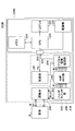
- FIG. 1 is a diagram showing the configuration of the ultrasound diagnostic system according to the first embodiment.
- the ultrasound diagnostic system 100 includes an ultrasound diagnostic apparatus 200 and a terminal device 300.
- the ultrasonic diagnostic apparatus 200 and the control apparatus 300 perform wireless communication.
- the ultrasound diagnostic apparatus 200 of the present embodiment includes an ultrasound image acquisition unit 210 including a probe 230, and a main body 220.
- the ultrasonic image acquisition unit 210 of the present embodiment and the main body 220 are electrically connected or separated by the connector 250.
- the ultrasonic image acquisition unit 210 including the probe 230 is attachable to and detachable from the main body 220.
- the ultrasound image acquisition unit 210 of the present embodiment has a probe 230 and an image processing unit 240.
- the probe 230 transmits (irradiates) an ultrasonic wave to a living body (subject) P and receives the reflected wave.
- the image processing unit 240 includes a control unit 241, a pulser switch unit 242, an AMP (amplifier), an ADC (analog to digital converter) unit 243, and a digital signal processing unit 244, and transmits an ultrasonic wave from the probe 230.
- the ultrasound image data based on the reflected wave (ultrasound) received by the probe 230 is generated and output to the main body 220.
- the control unit 241 controls the entire ultrasonic diagnostic apparatus 200.
- the control unit 241 is also connected to the connector 250 by I 2 C (I-squared-C) or the like.
- I 2 C I-squared-C
- the signal output from the main body unit 220 is input to the control unit 241 via the connector 250.
- the pulsar switch unit 242 selects the probe 230 by the switch unit, transmits a pulse signal to the probe 230, and causes the probe 230 to emit an ultrasonic wave to the living body P.
- the living body P When the living body P is irradiated with ultrasonic waves, the living body P reflects the ultrasonic waves at boundaries where acoustic impedances are different.
- the reflected wave reflected from the living body P is received by the probe 230, and is output to the AMP / ADC unit 243 selected by the switch unit of the pulsar switch unit 242.
- the AMP • ADC unit 243 amplifies the reflected wave of the ultrasonic wave output from the pulsar switch unit 242 by an amplifier (AMP), converts it into a digital signal by the ADC, and outputs the digital signal to the digital signal processing unit 244.
- AMP amplifier
- the digital signal processing unit 244 performs various types of processing on the digital signal output from the AMP / ADC unit 243, acquires ultrasound image data, and outputs the ultrasound image data to the main unit 220 via the connector 250.
- the processing performed by the digital signal processing unit 244 is processing for equalizing the delay from the timing when the reflected wave is output from the pulsar switch unit 242, averaging (phasing addition) processing, in the living body P And gain correction processing in consideration of the attenuation of the image, envelope processing for extracting luminance information, and the like.
- the digital signal processing unit 244 is connected to the connector 250 by SPI (Serial Peripheral Interface) or the like, and transmits ultrasound image data to the main unit 220 by SPI.
- SPI Serial Peripheral Interface
- the main body unit 220 of the present embodiment includes a wireless communication unit 221 and a power supply unit 222, and is connected to the ultrasound image acquisition unit 210 via the connector 250.
- the wireless communication unit 221 communicates with the terminal device 300. Specifically, for example, the wireless communication unit 221 performs wireless communication with the terminal device 300 according to the standard such as Wi-Fi.
- the standard used for wireless communication is not limited to Wi-Fi, and may be another standard.
- the wireless communication unit 221 is connected to the connector 250, and receives a signal transmitted from the terminal device 300. Specifically, the wireless communication unit 221 receives, for example, an irradiation instruction of ultrasonic waves from the terminal device 300.
- the wireless communication unit 221 of the present embodiment transmits the signal output from the ultrasound image acquisition unit 210 to the terminal device 300. Specifically, the wireless communication unit 221 transmits ultrasound image data to the terminal device 300.
- the power supply unit 222 is, for example, a chargeable and dischargeable secondary battery or the like, and supplies power to each unit of the ultrasonic diagnostic apparatus 200.
- the ultrasound image data is digitized by the ultrasound image acquisition unit 210 and then output to the main unit 220 as a digital signal.
- ultrasound image data to be delivered between the ultrasound image acquisition unit 210 and the main body unit 220 is a digital signal (digital data).
- the connector 250 for connecting the ultrasonic image acquisition unit 210 and the main body 220 can be configured in a simple manner.
- the ultrasonic image acquisition unit 210 and the main body 220 can be electrically connected or separated with a simple configuration. Further, according to the present embodiment, since the signal transferred through the connector 250 uses ultrasonic image data as a digital signal, the image quality by connecting or separating the ultrasonic image acquisition unit 210 and the main body unit 220 And the quality of ultrasound image data can be maintained.
- the terminal device 300 of the present embodiment includes a central processing unit (CPU) 310, a wireless communication unit 311, a memory 312, and a display 313.
- CPU central processing unit
- the CPU 310 controls the overall operation of the terminal device 300.
- the wireless communication unit 311 receives the signal transmitted from the ultrasonic diagnostic apparatus 200. Specifically, the wireless communication unit 311 receives ultrasonic image data transmitted from the ultrasonic diagnostic apparatus 200.
- the memory 312 stores ultrasonic image data received by the wireless communication unit 311, data as a result of calculation by the CPU 310, and the like.
- the display 313 displays ultrasonic image data and the like received from the ultrasonic diagnostic apparatus 200.
- the terminal device 300 of the present embodiment may be, for example, a tablet-type terminal device, and in that case, the display 313 includes a touch panel or the like.
- ultrasound image data is transmitted from the ultrasound diagnostic apparatus 200 to the terminal device 300 by wireless communication. Therefore, according to the present embodiment, when causing the living body P to scan the ultrasonic diagnostic apparatus 200, the movement of the operator of the ultrasonic diagnostic apparatus 200 is not limited by the communication cable or the like.
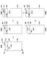
- FIG. 2 is a view for explaining attachment and detachment of the probe in the ultrasonic diagnostic apparatus of the first embodiment.
- State 1 shown in FIG. 2 shows a state in which the ultrasonic image acquisition unit 210 and the main body 220 are electrically connected by the connector 250.
- the substrate on which the image processing unit 240 is mounted and the substrate on which the main body unit 220 is mounted are housed in separate housings 270 and 280, respectively.
- a connector 250-1 having a convex connection portion is provided on the substrate on which the image processing unit 240 is mounted, and a connector 250-2 having a concave connection portion is provided on the substrate on which the main body portion 220 is mounted. Is provided. The connector 250-1 and the connector 250-2 can be inserted and removed from each other.
- the image processing unit 240 (ultrasound image acquisition unit 210) and the main body 220 are electrically connected, and the housing 270 and The housing 280 is connected.
- the connector 250-1 is convex and the connector 250-2 is concave, but the shape of the connector 250 is not limited to this.
- a mounting and demounting mechanism 260 for making the housing 270 and the housing 280 removable is provided.
- the attachment / detachment mechanism 260 is fixed to, for example, the housing 280, and the housing 270 is connected to the housing 280 in a state where the electrical connection between the ultrasonic image acquisition unit 210 and the main body 220 by the connector 250 is cut off. Make it possible to hold it
- the attachment / detachment mechanism 260 also allows the housing 270 to be removed from the housing 280.
- State 2 shown in FIG. 2 is a state in which the connector 250-1 and the connector 250-2 are separated, and the electrical connection between the ultrasonic image acquisition unit 210 and the main body 220 is cut off, and the housing A state in which the housing 270 and the housing 280 are connected by the mounting and demounting mechanism 260 is shown.
- the electrical connection between the ultrasonic image acquisition unit 210 and the main body 220 can be cut off, and the housing 270 can be connected to the housing 280.
- the present embodiment it is possible to suppress the loss of the case 270 in which the ultrasound image acquisition unit 210 is stored. In other words, the loss of the probe 230 removed from the main body 220 can be suppressed.
- State 3 shown in FIG. 2 shows a state in which the housing 270 is removed from the mounting and demounting mechanism 260.
- the state 3 indicates a state in which the case 270 in which the ultrasonic image acquisition unit 210 is stored is removed from the ultrasonic diagnostic apparatus 200.
- the housing 270 can be completely removed. Therefore, in the present embodiment, after the housing 270 is removed, as shown in state 4 and state 5, another ultrasonic image acquisition unit having a probe different in type from the probe 230 is accommodated.
- the housing 290 can be attached to the main body 220.
- the state 4 shows a state in which the housing 290 is attached to the mounting and demounting mechanism 260.
- the connector 250-1 is also provided on the substrate housed in the housing 290.
- the state 5 shows a state in which the ultrasonic image acquisition unit stored in the housing 290 and the main body 220 are electrically connected and connected by the housing 280, the housing 290, and the mounting and demounting mechanism 260.
- the state 5 indicates a state in which the ultrasound image acquisition unit 210 including the probe 230 is replaced by an ultrasound image acquisition unit including another probe.
- the probe can be replaced according to the application of the ultrasonic diagnostic apparatus 200.
- the attachment / detachment mechanism 260 may be configured. Further, in the present embodiment, the detaching mechanism 260 is configured to be in the state 3 in which the casing 270 is detached from the detaching mechanism 260 by further pulling the casing 270 away from the casing 280 from the state 2 You may.
- the ultrasonic diagnostic apparatus 200 of the present embodiment configures the attachment / detachment mechanism 260 so as to change from the state 1 to the state 2 by operating an operation member or the like provided on the case 270 or the case 280, for example. You may.
- the attachment / detachment mechanism 260 may be configured such that
- the probe 230 can be easily attached and detached with a simple configuration.
- the ultrasound diagnostic system of the second embodiment differs from the ultrasound diagnostic system of the first embodiment only in that communication between the ultrasound diagnostic apparatus and the terminal device is performed not by wireless but by wire. Therefore, in the following description of the second embodiment, only differences from the first embodiment will be described, and for those having the same functional configuration as the first embodiment, the description of the first embodiment The same reference numerals as the reference numerals used in FIG.
- FIG. 3 is a diagram showing the configuration of the ultrasound diagnostic system of the second embodiment.
- the ultrasound diagnostic system 100A of the present embodiment includes an ultrasound diagnostic apparatus 200A and a terminal device 300A.
- the ultrasound diagnostic apparatus 200A and the terminal device 300A communicate by wire.
- the ultrasound diagnostic apparatus 200A of the present embodiment includes an ultrasound image acquisition unit 210 and a main body 220A.
- the main body unit 220A includes a communication unit 221A and a power supply unit 222.
- the communication unit 221A of the present embodiment is connected to the connector 250, and transmits the ultrasonic image data received from the ultrasonic image acquisition unit 210 to the terminal device 300A by wired communication.
- the wired communication may be any communication method as long as it can be applied to communication between the ultrasonic diagnostic apparatus 200A and the terminal device 300A.
- the terminal device 300A of the present embodiment has a CPU 310, a communication unit 311A, a memory 312, and a display 313.
- the communication unit 311A of the present embodiment communicates with the ultrasonic diagnostic apparatus 200A by wire.
- the ultrasound diagnostic system 100A of the present embodiment even when the ultrasound diagnostic apparatus 200A and the terminal device 300A perform wired communication, the same effects as in the first embodiment can be obtained.
- the ultrasonic diagnostic apparatus of the third embodiment differs from the first embodiment in that it has a display. Therefore, in the following description of the third embodiment, only differences from the first embodiment will be described, and for those having the same functional configuration as the first embodiment, the description of the first embodiment The same reference numerals as the reference numerals used in FIG.
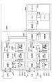
- FIG. 4 is a diagram showing the configuration of the ultrasound diagnostic system of the third embodiment.
- the ultrasound diagnostic apparatus 200B of the present embodiment includes an ultrasound image acquisition unit 210 and a main body 220B.
- the main body 220 ⁇ / b> B of the present embodiment includes a power supply unit 222, a CPU 223, a memory 224, and a display 225.
- the CPU 223 controls the operation of the main body 220B. Specifically, the CPU 223 is connected to the connector 250, and the ultrasound image data output from the ultrasound image acquisition unit 210 is input. When the ultrasound image data is input, the CPU 223 may cause the display 225 to display the ultrasound image data.
- the memory 224 stores ultrasonic image data acquired by the CPU 223, data as a result of calculation by the CPU 223, and the like.
- the display 225 displays ultrasound image data and the like acquired by the CPU 223.
- the display 225 may also display various types of information regarding the operation of the ultrasound diagnostic device 200B.
- the display 225 is provided in the ultrasound diagnostic apparatus 200B, ultrasound image data can be displayed without communicating with the terminal device 300.
- the terminal device 300 for displaying ultrasound image data is not necessary.
- the ultrasonic diagnostic apparatus according to the fourth embodiment differs from the first embodiment in that two probes can be connected to the main body 220. Therefore, in the following description of the fourth embodiment, only differences from the first embodiment will be described, and for those having the same functional configuration as the first embodiment, the description of the first embodiment The same reference numerals as the reference numerals used in FIG.
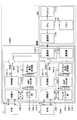
- FIG. 5 is a diagram showing the configuration of the ultrasound diagnostic system of the fourth embodiment.
- the ultrasound diagnostic system 100B of the present embodiment includes an ultrasound diagnostic apparatus 200C and a terminal device 300.
- the ultrasound diagnostic apparatus 200C and the terminal device 300 perform wireless communication.
- the ultrasound diagnostic apparatus 200C of the present embodiment has ultrasound image acquisition units 210-1 and 210-2, and a main body 220B.
- the ultrasound image acquisition unit 210-1 includes a probe 230-1 and an image processing unit 240-1.
- the ultrasound image acquisition unit 210-2 includes a probe 230-2 and an image processing unit 240-2.
- the probe 230-1 and the probe 230-2 are respectively different types of probes.
- the image processing unit 240-1 is set to correspond to the probe 230-1
- the image processing unit 240-2 is set to correspond to the probe 230-2.
- the ultrasound image acquisition unit 210-1 is connected to the main body 220B via the connector 250A, and the ultrasound image acquisition unit 210-2 is connected to the main body 220B via the connector 250B.
- the substrate on which the image processing unit 240-1 is mounted is provided with the connector 250A-1 having a convex connection portion, and the substrate on which the image processing unit 240-2 is mounted is connected A connector 250A-2 having a recessed portion is provided.
- the connector 250A-1 is connected to the connector 250A-2, and the connector 250B-1 is connected to the connector 250B-1.
- 250B-2 is provided.
- the connector 250B-1 and the connector 250B-2 are connected to the wireless communication unit 221, respectively.
- each of the image processing unit 240-1 and the image processing unit 240-2 is the same as that of the image processing unit 240, and thus the description thereof is omitted. Further, since the configuration of the main body 220B is the same as that of the main body 220, the description will be omitted.
- the ultrasonic image acquisition units 210-1 and 210-2 (probes 230-1 and 230-2) in the ultrasonic diagnostic apparatus 200C according to the present embodiment are attached to and detached from the main body 220B. Will be explained.
- FIG. 6 is a view for explaining attachment and detachment of the probe in the ultrasonic diagnostic apparatus of the fourth embodiment.
- state 1 the case 280 containing the ultrasonic image acquisition unit 210-1 and the ultrasonic image acquisition unit 210-2 are stored in the case 280 containing the substrate on which the main body 220B is mounted. It shows a state in which the boxed case 270-2 is attached.
- the ultrasound image acquisition unit 210-1 is pulled away from the main body 220B, the connector 250A-2 is pulled out of the connector 250A-1, and the ultrasound image acquisition unit 210-1 has an attachment / detachment mechanism.
- a state of being connected to the main body 220B by 260-1 is shown.
- an ultrasonic wave may be transmitted from the probe 230-2 of the ultrasonic image acquisition unit 210-2. That is, in the ultrasonic diagnostic apparatus 200C according to the present embodiment, when the probes 230-1 and 230-2 are electrically connected to the main body 220B, the probes 230-1 and 230 are used. -Do not send ultrasound from either of -2. Then, when one of the probes 230 and the main body 220B are electrically separated from each other, the ultrasonic diagnostic apparatus 200C is connected to the other probe 230 electrically connected to the main body 220B. Ultrasonic waves may be transmitted.
- the ultrasonic diagnostic apparatus 200C may transmit an ultrasonic wave from the probe 230 when there is one probe 230 electrically connected to the main body 220B.
- the states 4 and 5 in FIG. 6 are the same as the states 4 and 5 in FIG.
- the ultrasonic diagnostic apparatus 200C connects the housing 280 and the housing 270-2, and the main body 220B and the body 270B are connected.
- the ultrasound image acquisition unit 210-2 is electrically connected. That is, in the state 6, the ultrasonic diagnostic apparatus 200C is an ultrasonic diagnostic apparatus having one probe 230-2.
- the ultrasonic waves are transmitted from the probes 230.
- the present invention is not limited to this.
- the ultrasonic diagnostic apparatus 200C of this embodiment for example, as in state 1, from the terminal device 300 in a state where the probe 230-1 and the probe 230-2 are electrically connected to the main body 220B.
- the probe 230 for transmitting the ultrasonic wave may be selected based on the instruction of.
- the ultrasonic diagnostic apparatus 200C is provided with an operation member or the like for specifying the probe 230 for transmitting an ultrasonic wave, and the probe 230 selected by the operation member.
- ultrasonic waves may be transmitted.
- the plurality of probes 230 are provided in one ultrasonic diagnostic apparatus 200C, and the probes 230 to be used are connected to the main body 220B and the probes 230 not to be used. Can be separated from the main body 220B. Further, in the present embodiment, since the ultrasound image data transferred between the ultrasound image acquisition unit 210 having the probe 230 and the main body 220B is a digital signal, the probe 230 can be easily attached and detached. And maintain the quality of the ultrasound image.
- FIG. 7 is a diagram showing another configuration of the ultrasound diagnostic system of the fourth embodiment.
- An ultrasound diagnostic system 100C shown in FIG. 7 includes an ultrasound diagnostic apparatus 200D and a terminal device 300A.
- the ultrasound diagnostic apparatus 200D includes an ultrasound image acquisition unit 210-1, an ultrasound image acquisition unit 210-2, and a main body 220A.
- the ultrasonic diagnostic system 100C of this embodiment has the same configuration as the ultrasonic diagnostic system 100B of FIG. 5 except that the ultrasonic diagnostic apparatus 200D and the terminal device 300A communicate by wire, so the description will be omitted. .
- FIG. 8 is a view showing an ultrasonic diagnostic apparatus of the fourth embodiment.
- the ultrasound diagnostic apparatus 200E of the present embodiment has ultrasound image acquisition units 210-1 and 210-2 and a main body 220B.
- the ultrasonic image acquisition unit 210-1 is electrically connected to the main body 220B through the connector 250A
- the ultrasonic image acquisition unit 210-2 is electrically connected to the main body 220B through the connector 250B. .
- the ultrasonic diagnostic apparatus 200E shown in FIG. 8 has the same configuration as the ultrasonic diagnostic apparatus 200B of the third embodiment except that the ultrasonic image acquisition unit 210-2 is provided, and thus the description thereof is omitted.
- the probe and the image processing unit that digitizes ultrasonic image data Each ultrasound image acquisition unit including the is detachable. Therefore, according to the present embodiment, the image quality of the ultrasonic image is not deteriorated by attaching and detaching the probe.
- the signal line (cable) connecting the probe and the image processing unit is present inside the housing in which the probe and the image processing unit are housed, the user of the ultrasonic diagnostic apparatus There is no need to touch this signal line when attaching and detaching the probe.
- the probe can be easily attached and detached without deteriorating the image quality of the ultrasonic image.
- ultrasonic diagnostic apparatus 100, 100A to 100C ultrasonic diagnostic system 200, 200A to 200E ultrasonic diagnostic apparatus 210 ultrasonic image acquisition unit 220, 220A, 220B main unit 221 wireless communication unit 221A communication unit 222 power supply unit 225, 313 display 230 probe 240 Image processing unit 241 Control unit 242 Pulser switch unit 243 AMP / ADC unit 244 Digital signal processing unit 300, 300A Terminal device
Landscapes
- Health & Medical Sciences (AREA)
- Life Sciences & Earth Sciences (AREA)
- Engineering & Computer Science (AREA)
- Heart & Thoracic Surgery (AREA)
- Molecular Biology (AREA)
- Biophysics (AREA)
- Nuclear Medicine, Radiotherapy & Molecular Imaging (AREA)
- Pathology (AREA)
- Radiology & Medical Imaging (AREA)
- Biomedical Technology (AREA)
- Veterinary Medicine (AREA)
- Medical Informatics (AREA)
- Physics & Mathematics (AREA)
- Surgery (AREA)
- Animal Behavior & Ethology (AREA)
- General Health & Medical Sciences (AREA)
- Public Health (AREA)
- Computer Networks & Wireless Communication (AREA)
- Gynecology & Obstetrics (AREA)
- Ultra Sonic Daignosis Equipment (AREA)
Abstract
被検体に向けて超音波を送信し、前記被検体により反射された超音波を受信する探触子と、前記探触子により受信された超音波に基づく超音波画像データをデジタルデータに変換する画像処理部と、前記画像処理部から出力される前記デジタルデータを出力する本体部と、前記画像処理部と前記本体部との電気的な接続及び遮断を行うコネクタと、を有する超音波診断装置である。
Description
本発明は、超音波診断装置及び超音波診断システムに関する。
従来から、対象者に向けて超音波を照射し、対象者からの反射波を受信して超音波画像を取得する超音波診断装置が知られている。また、超音波診断装置によって超音波画像を撮像する際には、観察する対象の部位によって、超音波の周波数や、超音波の送受信を行う探触子の形状が異なることが知られている。
このため、従来では、対象部位に応じて、超音波の送受信を行う音響素子群を含む先端部(探触子)と、この先端部とケーブルを介して接続された装置本体とを着脱可能とした超音波診断装置が知られている。
探触子と装置本体との接続では、超音波の送受信を行うために多チャネルの信号線が必要となる。また、探触子が受信する超音波の反射波は、生体からの反射信号であるため、非常に微弱なアナログ信号となる。
このため、超音波画像の画質を維持するためには、探触子と装置本体とを接続するケーブルが非常に高価なものとなる上に、その取り扱いが難しく、装置本体に対して探触子を着脱することが容易にできない。
開示の技術は、上記事情に鑑みてこれを解決すべくなされたものであり、容易に探触子の着脱を行えるようにすることを目的としている。
開示の技術は、被検体に向けて超音波を送信し、前記被検体により反射された超音波を受信する探触子と、前記探触子により受信された超音波に基づく超音波画像データをデジタルデータに変換する画像処理部と、前記画像処理部から出力される前記デジタルデータを出力する本体部と、前記画像処理部と前記本体部との電気的な接続及び遮断を行うコネクタと、を有する超音波診断装置である。
容易に探触子の着脱を行える。
(第一の実施形態)
以下に図面を参照して、第一の実施形態について説明する。図1は、第一の実施形態の超音波診断システムの構成を示す図である。
以下に図面を参照して、第一の実施形態について説明する。図1は、第一の実施形態の超音波診断システムの構成を示す図である。
本実施形態の超音波診断システム100は、超音波診断装置200と、端末装置300とを有する。超音波診断装置200と、制御装置300とは、無線通信を行う。
はじめに、本実施形態の超音波診断装置200について説明する。本実施形態の超音波診断装置200は、探触子230を含む超音波画像取得部210と、本体部220と、を有する。
本実施形態の超音波画像取得部210と、本体部220とは、コネクタ250によって電気的に接続又は分離される。言い換えれば、本実施形態の超音波診断装置200において、探触子230を含む超音波画像取得部210は、本体部220に対して着脱可能となっている。
本実施形態の超音波画像取得部210は、探触子230と、画像処理部240とを有する。探触子230は、超音波を生体(被検体)Pに送信(照射)し、その反射波を受信する。
画像処理部240は、制御部241、パルサ・スイッチ部242、AMP(amplifier)・ADC(analog to digital converter)部243、デジタル信号処理部244を有し、探触子230から超音波を送信させ、探触子230が受信した反射波(超音波)に基づく超音波画像データを生成し、本体部220に出力する。
制御部241は、超音波診断装置200の全体を制御する。また、制御部241は、I2C(I-squared-C)等によって、コネクタ250と接続されている。本体部220から出力された信号は、コネクタ250を介して制御部241に入力される。
パルサ・スイッチ部242は、スイッチ部により探触子230を選択してパルス信号を探触子230に送信して、探触子230から超音波を生体Pに照射させる。
生体Pは、超音波が照射されると、音響インピーダンスが異なる境界においてその超音波を反射する。生体Pから反射された反射波は、探触子230によって受信され、パルサ・スイッチ部242のスイッチ部により選択されたAMP・ADC部243に出力される。
AMP・ADC部243は、パルサ・スイッチ部242から出力された超音波の反射波を、アンプ(AMP)により増幅して、ADCによりデジタル信号に変換して、デジタル信号処理部244に出力する。
デジタル信号処理部244は、AMP・ADC部243から出力されたデジタル信号に対して各種の処理を行って、超音波画像データを取得し、コネクタ250を介して本体部220へ出力する。
具体的には、デジタル信号処理部244で行われる処理は、パルサ・スイッチ部242から反射波が出力されたタイミングからの遅延分を揃える処理、平均化(整相加算)処理、生体P内での減衰を加味したゲイン補正処理、輝度情報を取り出す為の包絡線処理等を含む。
デジタル信号処理部244は、SPI(Serial Peripheral Interface)等によって、コネクタ250と接続されており、SPIによって超音波画像データを本体部220へ送信する。
本実施形態の本体部220は、無線通信部221と、電源部222と、を有し、コネクタ250を介して超音波画像取得部210と接続される。
無線通信部221は、端末装置300との通信を行う。具体的には、無線通信部221は、例えば、端末装置300と、Wi-Fi等の規格に応じた無線通信を行う。尚、無線通信に用いられる規格は、Wi-Fiに限定されず、他の規格であっても良い。
無線通信部221は、コネクタ250と接続されており、端末装置300から送信された信号を受信する。具体的には、無線通信部221は、例えば、超音波の照射指示等を端末装置300から受信する。
また、本実施形態の無線通信部221は、超音波画像取得部210から出力された信号を端末装置300へ送信する。具体的には、無線通信部221は、端末装置300へ超音波画像データを送信する。
電源部222は、例えば、充放電可能な二次電池等であり、超音波診断装置200の各部に電力を供給する。
このように、本実施形態の超音波診断装置200では、超音波画像取得部210によって超音波画像データがデジタル化された後に、デジタル信号として本体部220に出力される。言い換えれば、本実施形態によれば、超音波画像取得部210と本体部220との間で、受け渡しが行われる超音波画像データは、デジタル信号(デジタルデータ)となる。
また、本実施形態では、I2CやSPI等のバスを用いて信号の受け渡しを行うため、超音波画像取得部210と本体部220との間のインターフェイスを、数本のデジタル信号線で実現することができる。したがって、本実施形態によれば、超音波画像取得部210と本体部220とを接続するコネクタ250を簡易な構成とすることができる。
このため、本実施形態によれば、簡易な構成で、超音波画像取得部210と本体部220とを電気的に接続又は分離させることができる。また、本実施形態によれば、コネクタ250を介して受け渡しされる信号は、超音波画像データをデジタル信号とするため、超音波画像取得部210と本体部220とを接続又は分離させることによる画質の劣化は生じず、超音波画像データの画質を維持することができる。
次に、本実施形態の端末装置300について説明する。本実施形態の端末装置300は、CPU(Central Processing Unit)310、無線通信部311、メモリ312、ディスプレイ313を有する。
CPU310は、端末装置300の全体の動作を制御する。無線通信部311は、超音波診断装置200から送信された信号を受信する。具体的には、無線通信部311は、超音波診断装置200から送信される超音波画像データを受信する。
メモリ312は、無線通信部311が受信した超音波画像データや、CPU310による演算の結果のデータ等が格納される。
ディスプレイ313は、超音波診断装置200から受信した超音波画像データ等が表示される。
尚、本実施形態の端末装置300は、例えば、タブレット型の端末装置であっても良く、その場合には、ディスプレイ313は、タッチパネル等を備えるものになる。
本実施形態の超音波診断システム100では、超音波診断装置200から、無線通信によって、超音波画像データを端末装置300へ送信する。したがって、本実施形態によれば、超音波診断装置200を生体Pに走査させる際に、超音波診断装置200の操作者の動きが通信用のケーブル等によって制限されることがない。
次に、図2を参照して、本実施形態の超音波診断装置200における超音波画像取得部210(探触子230)の本体部220に対する着脱について説明する。
図2は、第一の実施形態の超音波診断装置における探触子の着脱を説明する図である。
図2に示す状態1は、超音波画像取得部210と本体部220とがコネクタ250によって電気的に接続されている状態を示す。
本実施形態の超音波診断装置200では、画像処理部240が実装された基板と、本体部220が実装された基板とが、それぞれ別々の筐体270、280に収納される。そして、画像処理部240が実装された基板には、接続部が凸型のコネクタ250-1が設けられており、本体部220が実装された基板には、接続部が凹型のコネクタ250-2が設けられている。コネクタ250-1とコネクタ250-2は、互いに抜き差し可能である。
本実施形態では、コネクタ250-1をコネクタ250-2に挿入することで、画像処理部240(超音波画像取得部210)と本体部220とが電気的に接続され、且つ、筐体270と筐体280とが連結される。尚、上述した説明では、コネクタ250-1が凸型とし、コネクタ250-2が凹型としているが、コネクタ250の形状はこれに限定されない。
また、本実施形態では、筐体270と、筐体280とを着脱可能とするための着脱機構260を有する。
着脱機構260は、例えば、筐体280に固定されており、コネクタ250による超音波画像取得部210と本体部220との電気的接続が遮断された状態において、筐体270を筐体280と連結した状態で保持できるようにする。また、着脱機構260は、筐体270を筐体280から取り外せるようにする。
図2に示す状態2は、コネクタ250-1とコネクタ250-2とが分離され、超音波画像取得部210と本体部220との電気的な接続が遮断された状態であり、且つ、筐体270と筐体280とが着脱機構260により連結した状態を示す。
このように、本実施形態では、超音波画像取得部210と本体部220との電気的な接続を遮断し、且つ、筐体270を筐体280と連結させた状態とすることができる。
したがって、本実施形態によれば、超音波画像取得部210が収納された筐体270の紛失を抑制することができる。言い換えれば、本体部220から取り外された探触子230の紛失を抑制することができる。
図2に示す状態3は、筐体270が着脱機構260から取り外された状態を示す。言い換えれば、状態3は、超音波診断装置200から、超音波画像取得部210が収納された筐体270が取り外された状態を示す。
本実施形態では、状態3のように、筐体270を完全に取り外すこともできる。したがって、本実施形態では、筐体270を取り外した後に、状態4、状態5に示すように、探触子230とは種類が異なる探触子を有する他の超音波画像取得部が収納された筐体290を本体部220に取り付けることができる。
状態4は、着脱機構260に、筐体290が取り付けられた状態を示す。尚、筐体290に収納された基板にも、コネクタ250-1が設けられるものとした。
状態4では、筐体280と筐体290とが着脱機構260によって連結されており、且つ、筐体290に収納されている超音波画像取得部と、本体部220とは、電気的に接続されていない状態を示す。
状態5は、筐体290に収納されている超音波画像取得部と、本体部220とが電気的に接続されて、筐体280と筐体290と着脱機構260により連結された状態を示す。言い換えれば、状態5は、探触子230を含む超音波画像取得部210が、他の探触子を含む超音波画像取得部に取り替えられた状態を示す
このように、本実施形態によれば、超音波診断装置200の用途に応じて探触子を交換することができる。尚、探触子は、例えば、リニアタイプ、コンベックスタイプ、セクタタイプ等の様々な種類、形状のものが存在している。
このように、本実施形態によれば、超音波診断装置200の用途に応じて探触子を交換することができる。尚、探触子は、例えば、リニアタイプ、コンベックスタイプ、セクタタイプ等の様々な種類、形状のものが存在している。
本実施形態では、例えば、筐体270を筐体280から引き離す方向に引くことで、コネクタ250-1からコネクタ250-2が引き抜かれ、且つ、筐体270と筐体280の連結が保持されるように、着脱機構260を構成しても良い。また、本実施形態では、状態2から、さらに筐体270を筐体280から離す方向に引くことで、着脱機構260から筐体270が取り外された状態3となるように、着脱機構260を構成しても良い。
また、本実施形態の超音波診断装置200は、例えば、筐体270又は筐体280に設けられた操作部材等を操作することで、状態1から状態2となるように、着脱機構260を構成しても良い。
また、本実施形態は、例えば、状態2において、筐体270を筐体280に近づけるように押し込むことで、コネクタ250-1にコネクタ250-2が差し込まれ、且つ、筐体270と筐体280が連結するように、着脱機構260が構成されていても良い。
このように、本実施形態によれば、簡易な構成で、容易に探触子230の着脱を行える。
(第二の実施形態)
以下に図面を参照して、第二の実施形態について説明する。第二の実施形態の超音波診断システムは、超音波診断装置と端末装置との間の通信を無線ではなく有線で行う点のみ、第一の実施形態と相違する。よって、以下の第二の実施形態の説明では、第一の実施形態との相違点についてのみ説明し、第一の実施形態と同様の機能構成を有するものには、第一の実施形態の説明で用いた符号と同様の符号を付与し、その説明を省略する。
以下に図面を参照して、第二の実施形態について説明する。第二の実施形態の超音波診断システムは、超音波診断装置と端末装置との間の通信を無線ではなく有線で行う点のみ、第一の実施形態と相違する。よって、以下の第二の実施形態の説明では、第一の実施形態との相違点についてのみ説明し、第一の実施形態と同様の機能構成を有するものには、第一の実施形態の説明で用いた符号と同様の符号を付与し、その説明を省略する。
図3は、第二の実施形態の超音波診断システムの構成を示す図である。本実施形態の超音波診断システム100Aは、超音波診断装置200Aと端末装置300Aとを有する。超音波診断システム100Aにおいて、超音波診断装置200Aと端末装置300Aとは、有線によって通信を行う。
本実施形態の超音波診断装置200Aは、超音波画像取得部210と、本体部220Aとを有する。本体部220Aは、通信部221Aと、電源部222と、を有する。
本実施形態の通信部221Aは、コネクタ250と接続されており、超音波画像取得部210から受信した超音波画像データを、有線による通信にて、端末装置300Aへ送信する。尚、有線による通信は、超音波診断装置200Aと端末装置300Aとの間の通信に適用できる通信方式によるものであれば、どのような方式であっても良い。
本実施形態の端末装置300Aは、CPU310、通信部311A、メモリ312、ディスプレイ313を有する。本実施形態の通信部311Aは、超音波診断装置200Aと有線にて通信を行う。
本実施形態の超音波診断システム100Aでは、超音波診断装置200Aと端末装置300Aとが有線による通信を行う場合であっても、第一の実施形態と同様の効果を奏することができる。
(第三の実施形態)
以下に図面を参照して、第三の実施形態について説明する。第三の実施形態の超音波診断装置は、ディスプレイを有する点が第一の実施形態と相違する。よって、以下の第三の実施形態の説明では、第一の実施形態との相違点についてのみ説明し、第一の実施形態と同様の機能構成を有するものには、第一の実施形態の説明で用いた符号と同様の符号を付与し、その説明を省略する。
以下に図面を参照して、第三の実施形態について説明する。第三の実施形態の超音波診断装置は、ディスプレイを有する点が第一の実施形態と相違する。よって、以下の第三の実施形態の説明では、第一の実施形態との相違点についてのみ説明し、第一の実施形態と同様の機能構成を有するものには、第一の実施形態の説明で用いた符号と同様の符号を付与し、その説明を省略する。
図4は、第三の実施形態の超音波診断システムの構成を示す図である。本実施形態の超音波診断装置200Bは、超音波画像取得部210と、本体部220Bと、を有する。
本実施形態の本体部220Bは、電源部222、CPU223、メモリ224、ディスプレイ225を有する。
CPU223は、本体部220Bの動作を制御する。具体的には、CPU223は、コネクタ250と接続されており、超音波画像取得部210から出力された超音波画像データが入力される。CPU223は、超音波画像データが入力されると、この超音波画像データをディスプレイ225に表示させても良い。
メモリ224は、CPU223が取得した超音波画像データや、CPU223による演算の結果のデータ等が格納される。
ディスプレイ225は、CPU223が取得した超音波画像データ等が表示される。また、ディスプレイ225は、超音波診断装置200Bの操作に関する各種の情報が表示されても良い。
このように、本実施形態によれば、超音波診断装置200Bにディスプレイ225が設けられているため、端末装置300と通信をせずに、超音波画像データを表示させることができる。言い換えれば、本実施形態によれば、超音波画像データを表示させるための端末装置300が不要となる。
(第四の実施形態)
以下に図面を参照して、第四の実施形態について説明する。第四の実施形態の超音波診断装置は、2つの探触子を本体部220に接続することができる点が第一の実施形態と相違する。よって、以下の第四の実施形態の説明では、第一の実施形態との相違点についてのみ説明し、第一の実施形態と同様の機能構成を有するものには、第一の実施形態の説明で用いた符号と同様の符号を付与し、その説明を省略する。
以下に図面を参照して、第四の実施形態について説明する。第四の実施形態の超音波診断装置は、2つの探触子を本体部220に接続することができる点が第一の実施形態と相違する。よって、以下の第四の実施形態の説明では、第一の実施形態との相違点についてのみ説明し、第一の実施形態と同様の機能構成を有するものには、第一の実施形態の説明で用いた符号と同様の符号を付与し、その説明を省略する。
図5は、第四の実施形態の超音波診断システムの構成を示す図である。本実施形態の超音波診断システム100Bは、超音波診断装置200Cと端末装置300とを有する。超音波診断システム100Aにおいて、超音波診断装置200Cと端末装置300とは、無線通信を行う。
本実施形態の超音波診断装置200Cは、超音波画像取得部210-1、210-2、本体部220Bを有する。
超音波画像取得部210-1は、探触子230-1と、画像処理部240-1とを有する。超音波画像取得部210-2は、探触子230-2と、画像処理部240-2とを有する。
探触子230-1と探触子230-2とは、それぞれが種類の異なる探触子である。また、画像処理部240-1は、探触子230-1と対応した設定がされており、画像処理部240-2は、探触子230-2と対応した設定がされている。
また、超音波画像取得部210-1は、コネクタ250Aを介して本体部220Bと接続され、超音波画像取得部210-2は、コネクタ250Bを介して本体部220Bと接続される。
つまり、本実施形態では、画像処理部240-1が実装された基板には、接続部が凸型のコネクタ250A-1が設けられ、画像処理部240-2が実装された基板には、接続部が凹型のコネクタ250A-2が設けられている。
また、本実施形態の本体部220Bが実装された基板には、コネクタ250A-1と接続される接続部が凹型のコネクタ250A-2と、コネクタ250B-1と接続される接続部が凹型のコネクタ250B-2と、が設けられている。
コネクタ250B-1とコネクタ250B-2は、それぞれが無線通信部221と接続される。
画像処理部240-1と画像処理部240-2のそれぞれの構成は、画像処理部240と同様であるから、説明を省略する。また、本体部220Bの構成は、本体部220と同様であるから、説明を省略する。
次に、図6を参照して、本実施形態の超音波診断装置200Cにおける超音波画像取得部210-1、210-2(探触子230-1、230-2)の本体部220Bに対する着脱について説明する。
図6は、第四の実施形態の超音波診断装置における探触子の着脱を説明する図である。状態1は、本体部220Bが実装された基板が収納された筐体280に、超音波画像取得部210-1が収納された筐体270-1と、超音波画像取得部210-2が収納された筐体270-2とが取り付けられた状態を示している。
状態2は、超音波画像取得部210-1が本体部220Bから離される方向に引かれ、コネクタ250A-1からコネクタ250A-2が引き抜かれ、且つ、超音波画像取得部210-1が着脱機構260-1によって本体部220Bと連結されている状態を示す。
本実施形態では、例えば、状態1から状態2となったときに、超音波画像取得部210-2の探触子230-2から、超音波が送信されるようにしても良い。つまり、本実施形態の超音波診断装置200Cでは、本体部220Bに探触子230-1、230-2が電気的に接続されている場合には、探触子230-1、探触子230-2のどちらからも超音波を送信させない。そして、超音波診断装置200Cは、探触子230の何れか一方と本体部220Bとが、電気的に分離されたとき、本体部220Bと電気的に接続されている他方の探触子230から超音波を送信させても良い。
言い換えれば、超音波診断装置200Cは、本体部220Bと電気的に接続された探触子230が1つとなった場合に、この探触子230から超音波を送信しても良い。
この場合、超音波診断装置200Cでは、状態2となったときに、超音波画像取得部210-2の探触子230-2からの超音波の送信が可能となる。
図6の状態4と状態5は、図2の状態4と状態5と同様であるから、説明を省略する。また、超音波診断装置200Cは、例えば、状態6に示すように、着脱機構260-1から筐体270を取り外されると、筐体280と筐体270-2とが連結され、本体部220Bと超音波画像取得部210-2とが電気的に接続された状態となる。つまり、状態6では、超音波診断装置200Cは、1つの探触子230-2を有する超音波診断装置となる。
尚、本実施形態では、本体部220Bと電気的に接続された探触子230が1つとなったときに、この探触子230から超音波を送信させるものとしたが、これに限定されない。本実施形態の超音波診断装置200Cは、例えば、状態1のように、探触子230-1、探触子230-2が電気的に本体部220Bと接続された状態において、端末装置300からの指示に基づいて、超音波を送信させる探触子230が選択されても良い。
また、本実施形態では、例えば、超音波診断装置200Cに、超音波を送信させる探触子230を指定するための操作部材等が設けられており、この操作部材によって選択された探触子230から、超音波を送信させても良い。
このように、本実施形態によれば、1台の超音波診断装置200Cに、複数の探触子230を設け、使用する探触子230を本体部220Bに接続し、使用しない探触子230を本体部220Bから分離することができる。また、本実施形態では、探触子230を有する超音波画像取得部210と本体部220Bとの間で受け渡しされる超音波画像データは、デジタル信号であるため、探触子230の着脱を容易に行うことができ、且つ、超音波画像の画質を維持することができる。
以下に、図7、図8について、本実施形態の他の例について説明する。図7は、第四の実施形態の超音波診断システムの他の構成を示す図である。
図7に示す超音波診断システム100Cは、超音波診断装置200Dと端末装置300Aとを有する。超音波診断装置200Dは、超音波画像取得部210-1、超音波画像取得部210-2と、本体部220Aとを有する。
本実施形態の超音波診断システム100Cでは、超音波診断装置200Dと端末装置300Aとが有線によって通信すること以外は、図5の超音波診断システム100Bと同様の構成であるから、説明を省略する。
図8は、第四の実施形態の超音波診断装置を示す図である。本実施形態の超音波診断装置200Eは、超音波画像取得部210-1、210-2と、本体部220Bとを有する。超音波画像取得部210-1は、コネクタ250Aを介して本体部220Bと電気的に接続され、超音波画像取得部210-2は、コネクタ250Bを介して本体部220Bと電気的に接続される。
図8に示す超音波診断装置200Eは、超音波画像取得部210-2を設けた点以外は、第三の実施形態の超音波診断装置200Bと同様の構成であるから、説明を省略する。
以上の説明したように、本実施形態によれば、超音波診断装置の本体部に対して探触子を着脱する際に、探触子と、超音波画像データをデジタル化する画像処理部とを含む超音波画像取得部ごと、着脱できるようにした。したがって、本実施形態によれば、探触子を着脱することで、超音波画像の画質が劣化することがない。また、探触子と画像処理部とを接続する信号線(ケーブル)は、探触子と画像処理部とが収納された筐体の内部に存在するため、超音波診断装置の利用者は、探触子の着脱の際にこの信号線に触れる必要がない。
したがって、本実施形態によれば、超音波画像の画質を劣化させずに、探触子の着脱を容易に行える。
以上、各実施形態に基づき本発明の説明を行ってきたが、上記実施形態に示した要件に本発明が限定されるものではない。これらの点に関しては、本発明の主旨をそこなわない範囲で変更することができ、その応用形態に応じて適切に定めることができる。
100、100A~100C 超音波診断システム
200、200A~200E 超音波診断装置
210 超音波画像取得部
220、220A、220B 本体部
221 無線通信部
221A 通信部
222 電源部
225、313 ディスプレイ
230 探触子
240 画像処理部
241 制御部
242 パルサ・スイッチ部
243 AMP・ADC部
244 デジタル信号処理部
300、300A 端末装置
200、200A~200E 超音波診断装置
210 超音波画像取得部
220、220A、220B 本体部
221 無線通信部
221A 通信部
222 電源部
225、313 ディスプレイ
230 探触子
240 画像処理部
241 制御部
242 パルサ・スイッチ部
243 AMP・ADC部
244 デジタル信号処理部
300、300A 端末装置
Claims (8)
- 被検体に向けて超音波を送信し、前記被検体により反射された超音波を受信する探触子と、
前記探触子により受信された超音波に基づく超音波画像データをデジタルデータに変換する画像処理部と、
前記画像処理部から出力される前記デジタルデータを出力する本体部と、
前記画像処理部と前記本体部との電気的な接続及び遮断を行うコネクタと、を有する超音波診断装置。 - 前記探触子と前記画像処理部とは、第一の筐体に収納されており、
前記本体部は、第二の筐体に収納されており、
前記第二の筐体に対して前記第一の筐体を着脱させる着脱機構を有する、請求項1記載の超音波診断装置。 - 前記着脱機構は、
前記コネクタによる前記画像処理部と前記本体部との電気的な接続が遮断された状態において、前記第一の筐体と前記第二の筐体とを連結させる、請求項2記載の超音波診断装置。 - 他の探触子と、前記他の探触子と対応した他の画像処理部と、
前記他の画像処理部と、前記本体部との電気的な接続及び遮断を行う他のコネクタと、を有し、
前記他の探触子と、前記他の画像処理部とは、第三の筐体に収納され、
前記第二の筐体に対して前記第三の筐体を着脱させる他の着脱機構を有する、請求項2又は3記載の超音波診断装置。 - 前記本体部は、
外部の端末装置と無線通信を行う無線通信部と、前記本体部、前記探触子及び前記画像処理部に電力を供給する電源部と、を有し、
前記デジタルデータを、前記無線通信部を介して前記端末装置へ出力する、請求項1乃至4の何れか一項に記載の超音波診断装置。 - 前記本体部は、
外部の端末装置と有線による通信を行う通信部と、前記本体部、前記探触子及び前記画像処理部に電力を供給する電源部と、を有し、
前記デジタルデータを、前記通信部を介して前記端末装置へ出力する、請求項1乃至4の何れか一項に記載の超音波診断装置。 - 前記本体部は、
前記本体部、前記探触子及び前記画像処理部に電力を供給する電源部と、前記デジタルデータを表示させる表示部と、を有する、請求項1乃至4の何れか一項に記載の超音波診断装置。 - 超音波診断装置と、端末装置とを有する超音波診断システムであって、
前記超音波診断装置は、
被検体に向けて超音波を送信し、前記被検体により反射された超音波を受信する探触子と、
前記探触子により受信された超音波に基づく超音波画像データをデジタルデータに変換する画像処理部と、
前記画像処理部から出力される前記デジタルデータを前記端末装置に出力する本体部と、
前記画像処理部と前記本体部との電気的な接続及び遮断を行うコネクタと、を有する超音波診断システム。
Priority Applications (4)
| Application Number | Priority Date | Filing Date | Title |
|---|---|---|---|
| JP2019549031A JP7078054B2 (ja) | 2017-10-17 | 2017-10-17 | 超音波診断装置及び超音波診断システム |
| CN201780095746.7A CN111212605B (zh) | 2017-10-17 | 2017-10-17 | 超声波诊断装置以及超声波诊断系统 |
| PCT/JP2017/037497 WO2019077675A1 (ja) | 2017-10-17 | 2017-10-17 | 超音波診断装置及び超音波診断システム |
| US16/843,445 US11534139B2 (en) | 2017-10-17 | 2020-04-08 | Ultrasonic diagnostic device and ultrasonic diagnostic system |
Applications Claiming Priority (1)
| Application Number | Priority Date | Filing Date | Title |
|---|---|---|---|
| PCT/JP2017/037497 WO2019077675A1 (ja) | 2017-10-17 | 2017-10-17 | 超音波診断装置及び超音波診断システム |
Related Child Applications (1)
| Application Number | Title | Priority Date | Filing Date |
|---|---|---|---|
| US16/843,445 Continuation US11534139B2 (en) | 2017-10-17 | 2020-04-08 | Ultrasonic diagnostic device and ultrasonic diagnostic system |
Publications (1)
| Publication Number | Publication Date |
|---|---|
| WO2019077675A1 true WO2019077675A1 (ja) | 2019-04-25 |
Family
ID=66173922
Family Applications (1)
| Application Number | Title | Priority Date | Filing Date |
|---|---|---|---|
| PCT/JP2017/037497 Ceased WO2019077675A1 (ja) | 2017-10-17 | 2017-10-17 | 超音波診断装置及び超音波診断システム |
Country Status (4)
| Country | Link |
|---|---|
| US (1) | US11534139B2 (ja) |
| JP (1) | JP7078054B2 (ja) |
| CN (1) | CN111212605B (ja) |
| WO (1) | WO2019077675A1 (ja) |
Cited By (2)
| Publication number | Priority date | Publication date | Assignee | Title |
|---|---|---|---|---|
| JP2022026906A (ja) * | 2020-07-31 | 2022-02-10 | 上田日本無線株式会社 | 振動子ユニットおよび超音波プローブ |
| JP2022189662A (ja) * | 2021-06-11 | 2022-12-22 | 上田日本無線株式会社 | 超音波プローブおよび無線超音波プローブ |
Families Citing this family (1)
| Publication number | Priority date | Publication date | Assignee | Title |
|---|---|---|---|---|
| CN112890860A (zh) * | 2021-01-20 | 2021-06-04 | 李逸丰 | 一种基于5g的超声波探测方法及装置 |
Citations (4)
| Publication number | Priority date | Publication date | Assignee | Title |
|---|---|---|---|---|
| JP2009060992A (ja) * | 2007-09-05 | 2009-03-26 | Panasonic Corp | 超音波診断装置 |
| JP2010227357A (ja) * | 2009-03-27 | 2010-10-14 | Fujifilm Corp | 超音波プローブ及び超音波プローブシステム |
| JP2010227356A (ja) * | 2009-03-27 | 2010-10-14 | Fujifilm Corp | 超音波プローブ及び超音波プローブシステム |
| JP2012090712A (ja) * | 2010-10-26 | 2012-05-17 | Fujifilm Corp | 無線超音波診断システム |
Family Cites Families (11)
| Publication number | Priority date | Publication date | Assignee | Title |
|---|---|---|---|---|
| JPH01181851A (ja) | 1988-01-12 | 1989-07-19 | Nippon Dempa Kogyo Co Ltd | 超音波探触子 |
| US5617866A (en) | 1996-01-05 | 1997-04-08 | Acuson Corporation | Modular transducer system |
| JP4809755B2 (ja) * | 2006-11-30 | 2011-11-09 | 日立アロカメディカル株式会社 | 超音波診断システム |
| US8465428B2 (en) * | 2009-03-27 | 2013-06-18 | Fujifilm Corporation | Ultrasonic probe and ultrasonic probe system |
| KR101175537B1 (ko) | 2010-11-23 | 2012-08-22 | 알피니언메디칼시스템 주식회사 | 스캔헤드가 분리가능한 프로브 |
| JP6067966B2 (ja) | 2011-10-18 | 2017-01-25 | 東芝メディカルシステムズ株式会社 | 超音波プローブ及び超音波診断装置 |
| JP6024120B2 (ja) | 2012-02-24 | 2016-11-09 | セイコーエプソン株式会社 | 超音波プローブ、プローブヘッド、電子機器及び診断装置 |
| CN104602612B (zh) * | 2012-10-19 | 2016-09-07 | 东芝医疗系统株式会社 | 超声波诊断装置以及超声波探针 |
| JP5613747B2 (ja) * | 2012-11-19 | 2014-10-29 | 富士フイルム株式会社 | 無線超音波診断システム |
| JP6390145B2 (ja) * | 2014-04-09 | 2018-09-19 | コニカミノルタ株式会社 | 超音波画像診断装置及び超音波画像診断装置の作動方法 |
| KR102390059B1 (ko) * | 2015-02-13 | 2022-04-25 | 삼성메디슨 주식회사 | 초음파 영상 장치 및 초음파 영상 장치의 제어 방법 |
-
2017
- 2017-10-17 JP JP2019549031A patent/JP7078054B2/ja active Active
- 2017-10-17 WO PCT/JP2017/037497 patent/WO2019077675A1/ja not_active Ceased
- 2017-10-17 CN CN201780095746.7A patent/CN111212605B/zh active Active
-
2020
- 2020-04-08 US US16/843,445 patent/US11534139B2/en active Active
Patent Citations (4)
| Publication number | Priority date | Publication date | Assignee | Title |
|---|---|---|---|---|
| JP2009060992A (ja) * | 2007-09-05 | 2009-03-26 | Panasonic Corp | 超音波診断装置 |
| JP2010227357A (ja) * | 2009-03-27 | 2010-10-14 | Fujifilm Corp | 超音波プローブ及び超音波プローブシステム |
| JP2010227356A (ja) * | 2009-03-27 | 2010-10-14 | Fujifilm Corp | 超音波プローブ及び超音波プローブシステム |
| JP2012090712A (ja) * | 2010-10-26 | 2012-05-17 | Fujifilm Corp | 無線超音波診断システム |
Cited By (4)
| Publication number | Priority date | Publication date | Assignee | Title |
|---|---|---|---|---|
| JP2022026906A (ja) * | 2020-07-31 | 2022-02-10 | 上田日本無線株式会社 | 振動子ユニットおよび超音波プローブ |
| JP7489256B2 (ja) | 2020-07-31 | 2024-05-23 | 上田日本無線株式会社 | 振動子ユニットおよび超音波プローブ |
| JP2022189662A (ja) * | 2021-06-11 | 2022-12-22 | 上田日本無線株式会社 | 超音波プローブおよび無線超音波プローブ |
| JP7680894B2 (ja) | 2021-06-11 | 2025-05-21 | 上田日本無線株式会社 | 超音波プローブおよび無線超音波プローブ |
Also Published As
| Publication number | Publication date |
|---|---|
| CN111212605A (zh) | 2020-05-29 |
| CN111212605B (zh) | 2022-09-27 |
| US20200229790A1 (en) | 2020-07-23 |
| JPWO2019077675A1 (ja) | 2020-11-05 |
| US11534139B2 (en) | 2022-12-27 |
| JP7078054B2 (ja) | 2022-05-31 |
Similar Documents
| Publication | Publication Date | Title |
|---|---|---|
| EP1905354A1 (en) | Signal replication medical apparatus | |
| JP5175914B2 (ja) | 無線超音波診断システム | |
| US20130116566A1 (en) | Ultrasonic diagnostic system and ultrasonic diagnostic method | |
| KR20150042870A (ko) | 저 전력 초음파 시스템 | |
| KR101348331B1 (ko) | 스마트폰과 기능적으로 연결된 청진기 | |
| WO2019077675A1 (ja) | 超音波診断装置及び超音波診断システム | |
| KR20100057341A (ko) | 무선 통신이 가능한 초음파 시스템 | |
| RU2011120136A (ru) | Низковольтная ультразвуковая система с высоковольтными датчиками | |
| JP2014521435A (ja) | 超音波診断のためのプローブの無線通信方法及びそのための装置 | |
| JP2008126086A (ja) | 圧力測定システムのトランシーバ装置 | |
| JP2009060992A (ja) | 超音波診断装置 | |
| JP5486901B2 (ja) | 超音波診断装置 | |
| US10856845B2 (en) | Ultrasound probe and ultrasound diagnosis device using the same | |
| JP5613747B2 (ja) | 無線超音波診断システム | |
| CN107847222A (zh) | 超声波图像生成系统以及超声波无线探测器 | |
| CN209863833U (zh) | 听力测试状态反馈系统 | |
| CN220089509U (zh) | 一种双频双通道内镜超声成像系统 | |
| KR20120059739A (ko) | 본체에 탈부착 가능한 psa부를 구비하는 초음파 시스템 | |
| JP7287513B2 (ja) | 超音波診断装置 | |
| CN211300058U (zh) | 一种探头 | |
| WO2023175867A1 (ja) | 超音波プローブ、及び超音波診断システム | |
| CN109893139B (zh) | 听力测试状态反馈系统 | |
| KR20090044075A (ko) | 무선 풋 인터페이스를 포함하는 초음파 시스템 | |
| JP2019180608A (ja) | 生体情報取得装置、アプリケーションプログラム及び生体情報取得方法 | |
| JPH062248U (ja) | 波形観測装置 |
Legal Events
| Date | Code | Title | Description |
|---|---|---|---|
| 121 | Ep: the epo has been informed by wipo that ep was designated in this application |
Ref document number: 17929011 Country of ref document: EP Kind code of ref document: A1 |
|
| ENP | Entry into the national phase |
Ref document number: 2019549031 Country of ref document: JP Kind code of ref document: A |
|
| NENP | Non-entry into the national phase |
Ref country code: DE |
|
| 122 | Ep: pct application non-entry in european phase |
Ref document number: 17929011 Country of ref document: EP Kind code of ref document: A1 |