WO2019069568A1 - 音響出力装置、イヤホン、補聴器及び携帯型端末装置 - Google Patents
音響出力装置、イヤホン、補聴器及び携帯型端末装置 Download PDFInfo
- Publication number
- WO2019069568A1 WO2019069568A1 PCT/JP2018/030615 JP2018030615W WO2019069568A1 WO 2019069568 A1 WO2019069568 A1 WO 2019069568A1 JP 2018030615 W JP2018030615 W JP 2018030615W WO 2019069568 A1 WO2019069568 A1 WO 2019069568A1
- Authority
- WO
- WIPO (PCT)
- Prior art keywords
- speaker
- hole
- opening
- sound
- output device
- Prior art date
Links
Images


Classifications
-
- H—ELECTRICITY
- H04—ELECTRIC COMMUNICATION TECHNIQUE
- H04R—LOUDSPEAKERS, MICROPHONES, GRAMOPHONE PICK-UPS OR LIKE ACOUSTIC ELECTROMECHANICAL TRANSDUCERS; DEAF-AID SETS; PUBLIC ADDRESS SYSTEMS
- H04R1/00—Details of transducers, loudspeakers or microphones
- H04R1/10—Earpieces; Attachments therefor ; Earphones; Monophonic headphones
- H04R1/1033—Cables or cables storage, e.g. cable reels
-
- H—ELECTRICITY
- H04—ELECTRIC COMMUNICATION TECHNIQUE
- H04R—LOUDSPEAKERS, MICROPHONES, GRAMOPHONE PICK-UPS OR LIKE ACOUSTIC ELECTROMECHANICAL TRANSDUCERS; DEAF-AID SETS; PUBLIC ADDRESS SYSTEMS
- H04R9/00—Transducers of moving-coil, moving-strip, or moving-wire type
- H04R9/06—Loudspeakers
-
- H—ELECTRICITY
- H04—ELECTRIC COMMUNICATION TECHNIQUE
- H04M—TELEPHONIC COMMUNICATION
- H04M1/00—Substation equipment, e.g. for use by subscribers
- H04M1/60—Substation equipment, e.g. for use by subscribers including speech amplifiers
- H04M1/6033—Substation equipment, e.g. for use by subscribers including speech amplifiers for providing handsfree use or a loudspeaker mode in telephone sets
- H04M1/6041—Portable telephones adapted for handsfree use
- H04M1/6058—Portable telephones adapted for handsfree use involving the use of a headset accessory device connected to the portable telephone
-
- H—ELECTRICITY
- H04—ELECTRIC COMMUNICATION TECHNIQUE
- H04R—LOUDSPEAKERS, MICROPHONES, GRAMOPHONE PICK-UPS OR LIKE ACOUSTIC ELECTROMECHANICAL TRANSDUCERS; DEAF-AID SETS; PUBLIC ADDRESS SYSTEMS
- H04R1/00—Details of transducers, loudspeakers or microphones
- H04R1/10—Earpieces; Attachments therefor ; Earphones; Monophonic headphones
- H04R1/1016—Earpieces of the intra-aural type
-
- H—ELECTRICITY
- H04—ELECTRIC COMMUNICATION TECHNIQUE
- H04R—LOUDSPEAKERS, MICROPHONES, GRAMOPHONE PICK-UPS OR LIKE ACOUSTIC ELECTROMECHANICAL TRANSDUCERS; DEAF-AID SETS; PUBLIC ADDRESS SYSTEMS
- H04R1/00—Details of transducers, loudspeakers or microphones
- H04R1/10—Earpieces; Attachments therefor ; Earphones; Monophonic headphones
- H04R1/1058—Manufacture or assembly
-
- H—ELECTRICITY
- H04—ELECTRIC COMMUNICATION TECHNIQUE
- H04R—LOUDSPEAKERS, MICROPHONES, GRAMOPHONE PICK-UPS OR LIKE ACOUSTIC ELECTROMECHANICAL TRANSDUCERS; DEAF-AID SETS; PUBLIC ADDRESS SYSTEMS
- H04R25/00—Deaf-aid sets, i.e. electro-acoustic or electro-mechanical hearing aids; Electric tinnitus maskers providing an auditory perception
- H04R25/60—Mounting or interconnection of hearing aid parts, e.g. inside tips, housings or to ossicles
- H04R25/604—Mounting or interconnection of hearing aid parts, e.g. inside tips, housings or to ossicles of acoustic or vibrational transducers
-
- H—ELECTRICITY
- H04—ELECTRIC COMMUNICATION TECHNIQUE
- H04R—LOUDSPEAKERS, MICROPHONES, GRAMOPHONE PICK-UPS OR LIKE ACOUSTIC ELECTROMECHANICAL TRANSDUCERS; DEAF-AID SETS; PUBLIC ADDRESS SYSTEMS
- H04R7/00—Diaphragms for electromechanical transducers; Cones
- H04R7/02—Diaphragms for electromechanical transducers; Cones characterised by the construction
- H04R7/12—Non-planar diaphragms or cones
-
- H—ELECTRICITY
- H04—ELECTRIC COMMUNICATION TECHNIQUE
- H04R—LOUDSPEAKERS, MICROPHONES, GRAMOPHONE PICK-UPS OR LIKE ACOUSTIC ELECTROMECHANICAL TRANSDUCERS; DEAF-AID SETS; PUBLIC ADDRESS SYSTEMS
- H04R9/00—Transducers of moving-coil, moving-strip, or moving-wire type
- H04R9/02—Details
- H04R9/025—Magnetic circuit
- H04R9/027—Air gaps using a magnetic fluid
-
- H—ELECTRICITY
- H04—ELECTRIC COMMUNICATION TECHNIQUE
- H04R—LOUDSPEAKERS, MICROPHONES, GRAMOPHONE PICK-UPS OR LIKE ACOUSTIC ELECTROMECHANICAL TRANSDUCERS; DEAF-AID SETS; PUBLIC ADDRESS SYSTEMS
- H04R2499/00—Aspects covered by H04R or H04S not otherwise provided for in their subgroups
- H04R2499/10—General applications
- H04R2499/11—Transducers incorporated or for use in hand-held devices, e.g. mobile phones, PDA's, camera's
-
- H—ELECTRICITY
- H04—ELECTRIC COMMUNICATION TECHNIQUE
- H04R—LOUDSPEAKERS, MICROPHONES, GRAMOPHONE PICK-UPS OR LIKE ACOUSTIC ELECTROMECHANICAL TRANSDUCERS; DEAF-AID SETS; PUBLIC ADDRESS SYSTEMS
- H04R25/00—Deaf-aid sets, i.e. electro-acoustic or electro-mechanical hearing aids; Electric tinnitus maskers providing an auditory perception
-
- H—ELECTRICITY
- H04—ELECTRIC COMMUNICATION TECHNIQUE
- H04R—LOUDSPEAKERS, MICROPHONES, GRAMOPHONE PICK-UPS OR LIKE ACOUSTIC ELECTROMECHANICAL TRANSDUCERS; DEAF-AID SETS; PUBLIC ADDRESS SYSTEMS
- H04R9/00—Transducers of moving-coil, moving-strip, or moving-wire type
- H04R9/02—Details
- H04R9/025—Magnetic circuit
Definitions
- the present disclosure relates to an acoustic output device, an earphone, a hearing aid, and a portable terminal device.
- Patent Document 1 discloses an earphone in which a sound hole penetrating the speaker is formed in the speaker. The sound holes communicate the space on the back side of the diaphragm of the speaker with the space on the back side of the speaker.
- Patent No. 6136016 gazette
- the air in the sound hole vibrates with the diaphragm to generate a flow of reciprocating air.
- the sound pressure frequency characteristic of the earphone may be unintended due to interference between an obstacle such as a cord disposed at the outlet of the sound hole and the air flow. .
- the present disclosure provides an acoustic output device, an earphone, a hearing aid, and a portable terminal device that improve sound pressure frequency characteristics.
- a sound output device includes: a speaker having a diaphragm; a speaker back space located at a back of the speaker opposite to the diaphragm; And a cable connected to the speaker back space and extending from the inside to the outside of the speaker back space, wherein the speaker is connected to a diaphragm back space located at the back of the diaphragm opposite to a sound radiation direction;
- the cable in the speaker back space when viewed from the first opening toward the second opening, includes a hole having a first opening that opens and a second opening that opens to the speaker back space. It is located outside the area of the hole.
- An earphone includes the above-mentioned sound output device.
- a hearing aid according to one non-limiting and exemplary aspect of the present disclosure comprises the above-mentioned sound output device.
- a portable terminal device includes the above-mentioned sound output device.
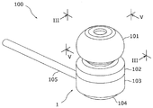
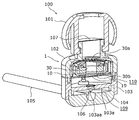
- FIG. 1 is a schematic perspective view of an example of an earphone provided with the sound output device according to the embodiment.
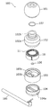
- FIG. 2 is a schematic exploded perspective view of the earphone of FIG.
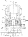
- FIG. 3 is a schematic cross-sectional side view looking in the direction III, the cross section of cutting the earphone of FIG. 1 through the cable and from the earpiece to the back cover.
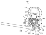
- FIG. 4 is a schematic perspective sectional view of the earphone of FIG. 1 with the same cross section as that of FIG. 3 cut away.
- FIG. 5 is a schematic perspective sectional view in which a cross section perpendicular to the cross section in FIG. 3 is cut away in the earphone of FIG. 1, and the cross section is viewed in the direction V.
- FIG. 1 is a schematic perspective view of an example of an earphone provided with the sound output device according to the embodiment.
- FIG. 2 is a schematic exploded perspective view of the earphone of FIG.
- FIG. 3 is a schematic cross-sectional side view
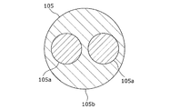
- FIG. 6 is a schematic cross-sectional view showing an example of the cross-sectional configuration of the cable.
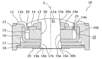
- FIG. 7 is a schematic cross-sectional side view showing the speaker of FIG. 3 in an enlarged manner.
- FIG. 8 is a view showing the earphone of FIG. 5 upside down.
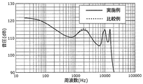
- FIG. 9 is a diagram showing sound pressure frequency characteristics in the example and the comparative example.
- FIG. 10 is a schematic view showing an example of a hearing aid to which the sound output device according to the embodiment is applied.
- FIG. 11 is a schematic view showing an example of a portable terminal device to which the sound output device according to the embodiment is applied.
- the present inventors examined the structure which has a sound hole in a speaker like the earphone of patent document 1 mentioned by "the background art" in examining a small and highly efficient sound output device.
- the air on the back side of the diaphragm in the speaker vibrates with the diaphragm and is subjected to compression or expansion. Air subjected to compression or expansion may affect the operation of the diaphragm.
- the provision of the sound holes increases the volume of the space on the back side of the diaphragm and reduces the pressure change of the space, so the above-mentioned influence is relatively low. It is suppressed.
- the present inventors have found a problem that a relationship between a desired sound pressure and a frequency of a diaphragm, that is, a sound pressure frequency characteristic can not be obtained in the process of examining the configuration of the earphone as described in Patent Document 1 .
- a sound pressure frequency characteristic can affect the sound pressure frequency characteristic.
- the air in the sound hole reciprocates along with the vibration of the diaphragm, whereby part of the air moves in and out of the sound hole.
- the outlet of the sound hole may be covered with a porous damping member in order to suppress excessive vibration of the air on the back side of the diaphragm.
- a porous damping member in order to suppress excessive vibration of the air on the back side of the diaphragm.
- a sound output device includes: a speaker having a diaphragm; a speaker back space located at a back of the speaker opposite to the diaphragm; and a speaker back space electrically connected to the speaker And a cable extending from the inside to the outside of the speaker, wherein the speaker comprises: a diaphragm back space located at the back of the diaphragm opposite to a sound radiation direction; a first opening opened to the diaphragm back space; And a hole having a second opening that opens into the speaker back space, wherein the cable in the speaker back space is disposed outside the area of the hole when viewed from the first opening toward the second opening It is done.
- the vibration in the diaphragm causes the air in the hole to vibrate and repeat the outflow and inflow to the speaker back space. Since the cable in the speaker back space is disposed outside the area of the hole, air flowing into the speaker back space is prevented from interfering with the cable. Thereby, since the pressure change of the air in the hole due to the interference between the outflow air and the cable is suppressed, it is possible to reduce the influence of the vibration of the diaphragm from the pressure change. Thus, the sound output device enables improvement in sound pressure frequency characteristics.
- the sound output device further includes a wall that forms the speaker back space between the speaker and the speaker, and the wall communicates the speaker back space with the second opening and the second opening.
- the cable may be disposed outside the area of the wall hole when viewed from the first opening toward the second opening.
- the air flowing out of the hole into the speaker back space smoothly flows out of the speaker back space through the wall hole. Therefore, the pressure change of the air in the hole due to the interference of the air flowing out to the speaker back space is suppressed.
- one region of the hole and the wall hole when viewed from the first opening toward the second opening, is the other of the hole and the wall hole. It may be included in the area.
- air can efficiently flow from the hole to the wall hole. Therefore, the air flowing out from the hole to the back space of the speaker is prevented from being interfered.
- the cable may be arranged to extend from the speaker in a direction along the hole in the speaker back space.
- the cable in the speaker back space can be easily disposed outside the area of the hole.
- the area occupied by the cable in the speaker back space can be kept low, the volume of air in the speaker back space can be increased.
- the speaker includes a magnet surrounding the hole, and a first member surrounding the hole and magnetically coupled to a first magnetic pole of the magnet.
- the voice coil includes a second member surrounding the hole and magnetically coupled to the second magnetic pole of the magnet, and a voice coil surrounding the hole and connected to the diaphragm.
- the magnetic gap may be disposed between a first facing portion of the first member and a second facing portion of the second member facing the first facing portion.
- the hole is formed to penetrate the first member, the second member and the magnet. Therefore, since the holes, the first member, the second member, the magnet, and the voice coil can be efficiently arranged, the speaker can be miniaturized.
- the speaker may further include a magnetic fluid disposed between at least one of the first facing portion and the second facing portion and the voice coil.
- the magnetic fluid stably holds the vibrating voice coil with respect to at least one of the first member and the second member. Therefore, the sound quality of the speaker can be improved.
- the speaker may further include a circuit board surrounding the hole and electrically connected to the voice coil and the cable.
- the hole is formed to penetrate the circuit board. Therefore, since the efficient arrangement of the circuit board in the speaker is possible, the speaker can be miniaturized.
- an earphone according to one aspect of the present disclosure includes the above-described sound output device. According to the above aspect, the same effect as the sound output device according to one aspect of the present disclosure can be obtained.
- a hearing aid according to an aspect of the present disclosure includes the above-described sound output device. According to the above aspect, the same effect as the sound output device according to one aspect of the present disclosure can be obtained.
- a portable terminal device includes the above-described sound output device. According to the above aspect, the same effect as the sound output device according to one aspect of the present disclosure can be obtained.
- substantially parallel means not only completely parallel but also substantially parallel, that is, including, for example, a difference of several% or so.
- each drawing is a schematic view, and is not necessarily illustrated exactly. Further, in the drawings, substantially the same components are denoted by the same reference numerals, and overlapping descriptions may be omitted or simplified.
- FIG. 1 shows a schematic perspective view of an example of an earphone provided with the sound output device 1 according to the embodiment.
- FIG. 2 shows a schematic exploded perspective view of the earphone 100 of FIG.
- FIG. 3 shows a schematic cross-sectional side view looking in the direction III of a cross section through the cable 105 and cutting the earphone 100 of FIG. 1 from the earpiece 101 to the back cover 104.
- the earphone 100 includes an earpiece 101, a port 102, a speaker 10, a box 103, a back cover 104, and a cable 105.
- the port 102 integrally has a bottomed cylindrical main body 102a and a sound conduit 102b extending from a bottom wall 102aa of the main body 102a.
- the earpiece 101 is a member to be inserted into the hole of the ear of the wearer of the earphone 100. Earpiece 101 is assembled to sound conduit 102 b of port 102.
- the earpiece 101 has a through hole 101a that opens in the outer ear of the wearer, and the through hole 101a communicates with the sound conduit 102b.
- the outer surface of the earpiece 101 may be constituted by an exposed surface of the constituent material of the earpiece 101, and may be covered with an elastic buffer material such as rubber or sponge. Note that the earpiece 101 itself may be formed of a buffer material having elasticity.
- the bottomed cylindrical box 103 is assembled with the main body 102 a of the port 102, and the box 103 and the main body 102 a form an accommodating space 108 therein.
- the housing space 108 is located between the bottom wall 103a of the box 103 and the bottom wall 102aa of the main body 102a, and communicates with the sound conduit 102b.
- the speaker 10 is disposed in the housing space 108 and emits sound toward the sound conduit 102 b. That is, the speaker 10 is disposed with the diaphragm 11 directed to the sound conduit 102b.
- the sound generated by the diaphragm 11 of the speaker 10 passes through the sound conduit 102 b and the through hole 101 a of the earpiece 101 to reach the wearer's ear.
- the bottomed cylindrical back cover 104 is assembled with the box 103 opposite the port 102.
- the back cover 104 covers the bottom wall 103 a of the box 103.
- the box 103 and the back cover 104 form a cable space 109 inside.
- the cable space 109 is located between the bottom wall 103 a of the box 103 and the bottom wall of the back cover 104 and communicates with the housing space 108.
- the back cover 104 is formed with an insertion hole 104 a through which the cable 105 passes. Although two insertion holes 104 a are formed in the example of FIGS. 2 and 3, they may be one.
- the cable 105 electrically connects the device to which the earphone 100 is connected and the speaker 10. That is, the cable 105 is electrically connected to the speaker 10.
- the cable 105 extends from the outside of the box 103 and the back cover 104 through the insertion hole 104 a into the cable space 109, and further extends into the housing space 108 and is connected to the speaker 10.
- the cable 105 extends from the inside to the outside of the speaker back space 110, which will be described later, formed in the housing space 108.
- the earpiece 101, the port 102, the box 103 and the back cover 104 constitute a housing (also referred to as a "housing") of the earphone.
- the earpiece 101, the port 102, the box 103 and the back cover 104 are arranged in this order and assembled to one another.
- the earpiece 101, the port 102, the box 103 and the back cover 104 are coaxially arranged on the axis C.
- the shape and arrangement of the earpiece 101, the port 102, the box 103 and the back cover 104 are not limited to the above, and any shape and arrangement may be employed.
- the housing space 108 is surrounded by a disk-shaped bottom wall 102 aa and a cylindrical side wall 102 ab of the main body 102 a of the port 102 and a disk-shaped bottom wall 103 a and a cylindrical side wall 103 b of the box 103.
- the speaker 10 is disposed at a distance from the bottom wall 103 a in the axis C direction.
- the axis C and the bottom wall 103 a are in a substantially perpendicular relationship, but the invention is not limited thereto.
- the speaker back space 110 is formed between the speaker 10 and the bottom wall 103a.
- the bottom wall 103 a forms a speaker back space 110 with the speaker 10.
- Such a speaker back space 110 is located at the back of the speaker 10 opposite to the diaphragm 11.
- the speaker back space 110 is surrounded by the speaker 10, the bottom wall 103a, and the side wall 103b.
- the speaker 10, the speaker back space 110 and the cable 105 constitute the sound output device 1.
- Bottom wall 103a is an example of a wall.
- the speaker 10 has a diaphragm back space 31 at the back of the diaphragm 11 opposite to the sound radiation direction. Furthermore, the speaker 10 has a sound hole 30.
- the sound hole 30 extends through the speaker 10 and communicates the diaphragm back space 31 and the speaker back space 110.
- the sound hole 30 has a first opening 30 a opening to the diaphragm back space 31 and a second opening 30 b opening to the speaker back space 110.
- the sound hole 30 is not limited to this, and in the present embodiment, the sound hole 30 is a straight linear hole along the axis C. Specifically, the axial center of the sound hole 30 is the axis C, but is not limited thereto.
- the sound hole 30 may be inclined with respect to the axis C, for example, and may include a curved linear shape.
- the sound hole 30 is an example of a hole.
- the speaker 10 has the 1st damping
- the first braking portion 19 enables the air in the sound hole 30 to flow out to the speaker back space 110 and the air in the speaker back space 110 to flow into the sound hole 30 while limiting them.
- Such first braking portion 19 suppresses excessive vibration of air in the sound hole 30 and prevents foreign matter from entering the sound hole 30.
- the first braking portion 19 is made of a porous material, and examples of the constituent material of the first braking portion 19 are an acoustic damping cloth, a material having a plurality of through holes, a mesh-like non-woven fabric, a woven fabric and the like.
- the cable 105 in the speaker back space 110 is an area occupied by the sound hole 30, that is, an area of the sound hole 30. It is arranged to be located outside.
- 4 is a schematic perspective sectional view of the earphone 100 of FIG. 1 with the same section as that of FIG. 3 cut away.
- FIG. 5 is a schematic perspective sectional view in which a cross section perpendicular to the cross section in FIG. 3 is cut away in the earphone 100 of FIG. 1, and the cross section is viewed in the direction V.
- the cable 105 includes two conductive core wires 105a and an electrically insulating sheath 105b covering the two core wires 105a. That the cable 105 is located outside the area of the sound hole 30 means that the two core wires 105 a and the outer skin 105 b are located outside the area of the sound hole 30. For example, if the cable 105 has one or more core wires 105a and a shell 105b, all the core wires 105a and the shell 105b are located outside the area of the sound hole 30. If the cable 105 does not have the sheath 105 b, all the core wires 105 a are located outside the area of the sound hole 30.
- 6 is a schematic cross-sectional view showing an example of the cross-sectional configuration of the cable 105. As shown in FIG.
- the area of the sound hole 30 is also the area of the sound hole 30 when the sound hole 30 is viewed in the direction of the axis C.
- the sound hole 30 is viewed along a straight line connecting the center of the first opening 30a and the center of the second opening 30b. It may be When the linear shape of the sound hole 30 includes a bend such as a curve, looking from the first opening 30 a toward the second opening 30 b is to look in a linear tangential direction of the sound hole 30 at the second opening 30 b It is also good.
- the area of the sound hole 30 is an area of the minimum cross section of the sound hole 30 when viewed from the first opening 30a toward the second opening 30b, an area of the maximum cross section of the sound hole 30, or an area of the second opening 30b. It may be either.
- the area of the sound hole 30 may be the area of the second opening 30b.
- a wall portion hole 103aa penetrating the bottom wall 103a is formed in the bottom wall 103a of the box 103.
- the wall hole 103aa communicates the speaker back space 110 with the cable space 109. That is, the wall holes 103aa communicate the speaker back space 110 to the outside.
- the wall hole 103 aa is opened opposite to the second opening 30 b of the sound hole 30.
- the bottom wall 103a is provided with a second braking portion 106 which covers the opening 103ab of the wall hole 103aa.
- the second braking portion 106 has the same function as the first braking portion 19, suppresses excessive vibration of air in the speaker back space 110, and prevents foreign matter from entering the speaker back space 110.
- the constituent material of the second braking portion 106 may be the same material as the material described above for the first braking portion 19.
- the third braking portion 107 covering the opening of the sound conduit 102b is also provided in the sound conduit 102b of the port 102.
- the third braking portion 107 has the same function as the first braking portion 19, suppresses excessive vibration of air in the sound conduit 102b, and prevents foreign matter from entering the sound conduit 102b.
- the constituent material of the third braking portion 107 may be the same material as the material described above for the first braking portion 19.
- the cable 105 in the speaker back space 110 when viewed from the first opening 30a to the second opening 30b, is disposed outside the region of the wall hole 103aa.
- the area of the wall hole 103aa is the area of the minimum cross section of the wall hole 103aa when viewed from the first opening 30a toward the second opening 30b, the area of the maximum cross section of the wall hole 103aa, or the speaker back space 110 It may be any of the area of the opening 103ab of the wall hole 103aa.
- the cable 105 may be located in the region of the wall hole 103aa.
- the cable 105 in the speaker back space 110 when viewed from the first opening 30a to the second opening 30b, is located outside the area of the sound hole 30, and the wall It is located in the outer side of the area
- the cable 105 in the speaker back space 110 is located at least outside the area of the sound hole 30.
- the cable 105 in the speaker back space 110 may be located outside the area connecting the second opening 30 b of the sound hole 30 and the opening 103 ab of the wall hole 103 aa.
- one region of the sound hole 30 and the wall hole 103aa is included in the other region of the sound hole 30 and the wall hole 103aa.
- the region of the wall hole 103 aa is included in the region of the sound hole 30.
- the sound hole 30 and the wall hole 103aa are coaxially arranged.
- the region of the sound hole 30 may be included in the region of the wall hole 103aa.
- the relative positional relationship between the sound hole 30 and the wall hole 103aa is not limited to the above as long as the wall hole 103aa faces the second opening 30b of the sound hole 30.
- the opening area of the opening 103ab of the wall hole 103aa is preferably equal to or larger than the opening area of the second opening 30b of the sound hole 30.
- the equal or more than the above means that the opening area of the opening 103ab itself is the opening of the second opening 30b itself It is to be equal to or greater than the area.
- the equal or more than the above means that the opening area of the opening 103ab itself is equal to or more than the opening area of the first braking portion 19 in the second opening 30b. It is a certain thing.
- the equal or more than the above means that the opening area of the second braking portion 106 in the opening 103ab is equal to or more than the opening area of the second opening 30b itself. It is.
- the opening area of the second braking portion 106 in the opening 103ab is the second opening 30b when the first braking portion 19 and the second braking portion 106 are equal to or more than the above. It is equal to or more than the opening area of the first braking portion 19 in the inside.
- the cable space 109 is formed between the bottom wall 103 a of the box 103 and the back cover 104.
- the cable space 109 communicates with the outside of the box 103 and the back cover 104, that is, the outside of the housing of the earphone 100 formed by them.
- the cable 105 extends from the outside of the box 103 and the back cover 104 into the cable space 109 along the bottom wall 103 a.
- the cable 105 changes direction and extends in the direction along the sound hole 30, passes through the through hole 103ac formed in the bottom wall 103a, and extends into the speaker back space 110.
- the cable 105 extends in the direction along the sound hole 30 in the speaker back space 110 and is connected to the speaker 10. In other words, the cable 105 extends from the speaker 10 in the direction along the sound hole 30 in the speaker back space 110.
- FIG. 7 is a schematic cross-sectional side view showing the speaker 10 of FIG. 3 in an enlarged manner.
- the speaker 10 includes a housing 12 and a diaphragm 11 attached to the housing 12 and emits sound by vibrating the diaphragm 11.
- the outer shape of the speaker 10 is a cylindrical shape, but is not limited thereto, and may be any shape.
- the speaker 10 includes the diaphragm 11, the housing 12, the stopper 13, the plate 14, the magnet 15, the yoke 16, the spacer 17, the circuit board 18, the first braking portion 19, and the voice coil 20. Equipped with
- the circular diaphragm 11 integrally includes a disk-shaped diaphragm body 11 a and an annular or ring-shaped diaphragm edge 11 b surrounding the outer periphery of the diaphragm body 11 a.
- the diaphragm edge 11 b is flexible, and the diaphragm body 11 a is more rigid than the diaphragm edge 11 b.
- the outer peripheral edge of the diaphragm edge 11 b is fixed to the housing 12.
- the diaphragm body 11a is connected to the voice coil 20, and vibrates together with the diaphragm edge 11b while deforming the diaphragm edge 11b by the vibration of the voice coil 20.
- the stopper 13, the plate 14, the magnet 15, the yoke 16, the spacer 17, the circuit board 18, the first braking portion 19 and the voice coil 20 are disposed inside the cylindrical casing 12.
- the stopper 13, the plate 14, the magnet 15, the yoke 16, the spacer 17 and the circuit board 18 are stacked and arranged in this order in the axial center direction of the housing 12 and joined together.
- the axial center of the housing 12 is the axis C, but is not limited thereto.
- the circuit board 18 includes an electric circuit and a terminal (not shown), and converts an electric signal of sound supplied from the outside of the speaker 10 through the cable 105 and supplies the electric signal to the voice coil 20.
- the circuit board 18 has an annular plate shape having a through hole 18 a at the center.
- the through hole 18 a constitutes a part of the sound hole 30.
- the circuit board 18 is joined to the two core wires 105 a of the cable 105.
- the two core wires 105a joined to the circuit board 18 are located outside the through holes 18a.
- FIG. 8 is a view showing the earphone 100 of FIG. 5 upside down.
- the first braking portion 19 is attached to the circuit board 18 so as to cover the through holes 18 a of the circuit board 18 from the outside.
- the first braking portion 19 is made of a porous material in at least the region 19a facing the through hole 18a.
- the spacers 17 are disposed between the circuit board 18 and the yoke 16 to separate them from one another.
- the spacer 17 has an annular plate shape having a through hole 17a at the center.
- the through hole 17 a constitutes a part of the sound hole 30.
- the spacer 17 may be omitted.
- the yoke 16 is made of a magnetic material.
- the yoke 16 has a cylindrical shape with a bottom, and has an annular plate-like bottom and a cylindrical tube 16b.
- the bottom has a through hole 16a at the center.
- the through hole 16 a constitutes a part of the sound hole 30.
- the yoke 16 is disposed with its bottom portion in contact with the spacer 17.
- the yoke 16 is an example of a second member.
- the magnet 15 is a member having two magnetic poles which are opposite poles.
- An example of the magnet 15 is a permanent magnet.
- the magnet 15 has a cylindrical shape having a through hole 15a at the center.
- the through hole 15 a constitutes a part of the sound hole 30.
- the magnet 15 is disposed inside the cylindrical portion 16 b of the yoke 16 so as to abut on and coaxial with the yoke 16.
- a cylindrical air gap is formed between the outer peripheral surface of the magnet 15 and the cylindrical portion 16 b.
- a second magnetic pole, which is one of the two magnetic poles of the magnet 15, is magnetically coupled to the yoke 16.
- the plate 14 is made of a magnetic material.
- the plate 14 is disposed on the inner side of the cylindrical portion 16 b of the yoke 16 on the opposite side to the bottom of the yoke 16 with respect to the magnet 15.
- the plate 14 has an annular plate shape having a through hole 14a at the center.
- the through hole 14 a constitutes a part of the sound hole 30.
- the plate 14 abuts on and coaxially with the magnet 15.
- the plate 14 is magnetically coupled to a first pole opposite to the second pole, which is the other of the two poles of the magnet 15.
- the cylindrical portion 16b of the yoke 16 is disposed outward of the outer peripheral edge 14b of the plate 14, specifically, disposed radially outward of the outer peripheral edge 14b, and is opposed to the outer peripheral edge 14b.
- a magnetic air gap 22 which is an air gap is formed between the outer peripheral edge 14 b and the inner circumferential surface of the cylindrical portion 16 b. In the magnetic gap 22, a magnetic field is formed between the outer peripheral edge 14b and the cylindrical portion 16b from one to the other.
- the outer peripheral edge 14b of the plate 14 is an example of the first opposing portion of the first member
- the cylindrical portion 16b of the yoke 16 is an example of the second opposing portion of the second member.
- the plate 14 as described above, the magnet 15 and the yoke 16 form a magnetic circuit through which magnetic flux circulates.
- the stopper 13 is disposed on the plate 14 and the magnet 15 to fix the plate 14 to the magnet 15.
- the stopper 13 has an annular shape having a through hole 13a at the center.
- the through hole 13 a constitutes a part of the sound hole 30.
- the provision of the stopper 13 reduces the volume of the diaphragm back space 31, which is the space between the plate 14 and the diaphragm body 11a. Since the volume of the diaphragm back space 31 relates to the sound quality of the speaker 10, the stopper 13 is also provided to adjust the volume of the diaphragm back space 31.
- the voice coil 20 is composed of a cylindrically wound wire.
- the voice coil 20 is disposed in the magnetic air gap 22 and surrounds the outer peripheral edge 14 b of the plate 14 from the outside.
- the voice coil 20 is spaced apart and coaxial with the plate 14 and the yoke 16.
- the voice coil 20 is joined to the diaphragm body 11 a of the diaphragm 11. Further, the voice coil 20 is electrically connected to the circuit board 18.
- the voice coil 20 oscillates in the direction of the axis C by the action of the magnetic field in the magnetic gap 22.
- the diaphragm 11 vibrates, causing a pressure change in the air on the outer surface and the inner surface of the diaphragm 11, thereby generating a sound wave. At this time, the diaphragm 11 emits a sound wave from the outer surface opposite to the diaphragm back space 31.
- the sound hole 30 penetrates the stopper 13, the plate 14, the magnet 15, the yoke 16, the spacer 17 and the circuit board 18.
- the voice coil 20 also surrounds the sound hole 30.
- the through hole 13 a of the stopper 13 constitutes a first opening 30 a of the sound hole 30, and the through hole 18 a of the circuit board 18 constitutes a second opening 30 b of the sound hole 30.
- the speaker 10 includes the magnetic fluid 21.
- the magnetic fluid 21 is filled in the magnetic air gap 22 between the voice coil 20 and the outer peripheral edge 14 b of the plate 14.
- the magnetic fluid 21 is packed around the entire circumference of the outer peripheral edge 14 b and distributed in an annular shape.
- the magnetic fluid 21 is a fluid containing a material having magnetism.
- An example of the magnetic fluid 21 is composed of ferromagnetic fine particles (for example, about 10 nm in diameter) such as magnetite and manganese zinc ferrite, a surfactant that covers the surface of the ferromagnetic fine particles, and a base solution such as water and oil. It is a magnetic colloid solution.
- the magnetic fluid 21 is liquid, it has a property of being magnetized and attracted to a magnet.
- the magnetic fluid 21 may be disposed between the voice coil 20 and the cylindrical portion 16 b of the yoke 16, and between the voice coil 20 and the cylindrical portion 16 b of the yoke 16 and between the voice coil 20 and the plate 14. It may be located at In other words, the magnetic fluid 21 may be disposed between the voice coil 20 and at least one of the cylindrical portion 16 b of the yoke 16 and the outer peripheral edge 14 b of the plate 14.
- Such magnetic fluid 21 is held between the voice coil 20 and the outer peripheral edge 14 b of the plate 14 by the magnetic force generated by the magnetic field in the magnetic gap 22 to form a fluid O-ring. Then, the voice coil 20 is supported by the magnetic fluid 21 and the plate 14 by the magnetic force passing through the magnetic fluid 21, whereby the position of the voice coil 20 with respect to the outer peripheral edge 14b is maintained. Moreover, the magnetic fluid 21 seals between the voice coil 20 and the outer peripheral edge 14b by functioning as a fluid O-ring. Therefore, the space on the back side of the diaphragm edge 11 b generating the sound wave and the diaphragm back space 31 are blocked by the magnetic fluid 21. The air in the space on the back side of the diaphragm edge 11 b generating the sound wave is suppressed from leaking to the diaphragm back space 31, whereby the decrease in the sound pressure of the speaker 10 is suppressed.
- the magnetic fluid 21 is provided with center retention. Therefore, even when the voice coil 20 vibrates with a large amplitude, the magnetic fluid 21 does not contact the diaphragm 11 and the voice coil 20 with the plate 14 and the yoke 16 by the center holding force. It can vibrate stably.
- the circuit board 18 of the speaker 10 converts the electric signal of the sound sent through the cable 105 and outputs the electric signal to the voice coil 20.
- the voice coil 20 vibrates in the direction of the axis C in response to the received signal to vibrate the diaphragm 11.
- the diaphragm 11 causes a pressure change in the air on the outer surface and the inner surface, thereby emitting a sound wave toward the sound conduit 102b.
- the sound wave emitted to the sound conduit 102 b is emitted from the through hole 101 a of the earpiece 101 into the outer ear of the wearer of the earphone 100.
- the air in the diaphragm back space 31 and the sound hole 30 vibrates to increase or decrease the pressure.
- the end of the diaphragm back space 31 is sealed by the magnetic fluid 21. Due to the increase and decrease of the pressure, air reciprocates between the sound hole 30 and the speaker back space 110 through the first braking portion 19.
- the air flowing out of the sound hole 30 into the speaker back space 110 forms a jet stream directed from the second opening 30 b of the sound hole 30 to the wall hole 103 aa when passing through the plurality of holes of the first braking portion 19.
- the jet flow smoothly flows toward the wall hole 103aa without interfering with the cable 105, flows into the cable space 109 through the wall hole 103aa, and flows out from the insertion hole 104a of the back cover 104.
- a reaction force in the direction opposite to the flow direction of the jet flow is generated in the first braking portion 19.
- the parameters of the reaction force are the jet velocity of air, the air density in the sound hole 30, and the opening area of the first braking portion 19.
- the ejection velocity of the air depends on the compression pressure of the air in the sound hole 30.
- the compression pressure of air that is, the jet velocity of the air
- the reaction force received by the first braking unit 19 changes.
- the change in reaction force at the first braking portion 19 affects the vibration of the diaphragm 11 through the air in the diaphragm back space 31 and the sound hole 30. Therefore, the sound pressure generated by the diaphragm 11 may not achieve the desired sound pressure.
- the cable 105 is disposed as described above with respect to the sound hole 30 and the wall hole 103 aa, the interference between the jet flow and the cable 105 is suppressed. Thus, the sound pressure generated by the diaphragm 11 can achieve a desired sound pressure.
- FIG. 9 shows a result of comparison between an example of the earphone 100 according to the embodiment and a comparative example of an earphone having a configuration in which the cable 105 is disposed close to the front of the second opening 30 b of the sound hole 30. It is shown.
- FIG. 9 is a figure which shows the sound pressure frequency characteristic in an Example and a comparative example.
- the relationship between the sound pressure and the frequency in the example is shown by a solid line graph
- the relationship between the sound pressure and the frequency in the comparative example is shown by a broken line graph. As shown in FIG. 9, it can be seen that the relationship between the sound pressure and the frequency changes between the example and the comparative example.
- the high frequency sound pressure decreases due to the mass of air on the outer surface or front surface of the diaphragm.
- the user wearing such an earphone actually listens, the user can hear only the low tone clearly, and the high tone can be heard as a consonant sound of a vocal voice and a muffled sound such as an individual's difference.
- the sound tends to be stagnant. This tendency is determined by the relative sound pressure difference between the low frequency sound pressure and the sound pressure in the above frequency band. Specifically, when the difference is large, the sound stagnation becomes remarkable. For this reason, the sound quality is improved as the sound pressure in the frequency band is closer to the sound pressure at a lower frequency.
- the cable 105 in the speaker back space 110 is the sound hole 30 when viewed from the first opening 30 a to the second opening 30 b of the sound hole 30.
- the vibration of the diaphragm 11 of the speaker 10 causes the air in the sound hole 30 to vibrate, and the outflow and the inflow to the speaker back space 110 are repeated.
- the cable 105 in the speaker back space 110 is disposed outside the area of the sound hole 30, so that the air flowing into the speaker back space 110 is prevented from interfering with the cable 105.
- the sound output device 1 enables the improvement of the sound pressure frequency characteristic.
- the cable 105 in the speaker back space 110 is disposed outside the area of the hole 103aa. According to the above aspect, the air flowing out of the sound hole 30 into the speaker back space 110 smoothly flows out of the speaker back space 110 through the wall hole 103 aa. Therefore, the pressure change of the air in the sound hole 30 due to the interference of the air flowing out to the speaker back space 110 is suppressed.
- one region of the sound hole 30 and the wall hole 103aa is the sound hole 30 and the wall It is included in the other area
- the cable 105 is arranged to extend from the speaker 10 in the direction along the sound hole 30 in the speaker back space 110.
- the cable 105 in the speaker back space 110 can be easily disposed outside the area of the sound hole 30.
- the area occupied by the cable 105 in the speaker back space 110 can be kept low, the volume of air in the speaker back space 110 can be increased. Thereby, since the pressure fluctuation of the speaker back space 110 at the time of the vibration of the air in the sound hole 30 is suppressed low, the influence of the air in the speaker back space 110 on the air in the sound hole 30 is suppressed.
- the sound hole 30 is formed to penetrate the plate 14 of the speaker 10, the yoke 16 and the magnet 15. According to the above aspect, since the sound holes 30, the plate 14, the yoke 16, the magnet 15, and the voice coil 20 can be efficiently arranged, the speaker 10 can be miniaturized.
- the speaker 10 includes the magnetic fluid 21 disposed between the voice coil 20 and at least one of the outer peripheral edge 14 b of the plate 14 and the cylindrical portion 16 b of the yoke 16. According to the above aspect, the magnetic fluid 21 stably holds the vibrating voice coil 20 against at least one of the plate 14 and the yoke 16. Therefore, the sound quality of the speaker 10 can be improved.
- the sound hole 30 is formed to penetrate the circuit board 18 of the speaker 10. According to the above aspect, since the efficient arrangement of the circuit board 18 in the speaker 10 is possible, the speaker 10 can be miniaturized.
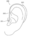
- FIG. 10 is a schematic view showing an example of a hearing aid to which the sound output device 1 according to the embodiment is applied.
- the hearing aid 200 comprises a receiver 201, a hearing aid body 202 and a lead tube 203.
- the configuration of the receiver 201 conforms to the configuration of the earpiece 101 of the earphone 100, the port 102, and the sound output device 1.
- FIG. 11 is a schematic view showing an example of a portable terminal device to which the sound output device 1 according to the embodiment is applied.
- the sound output device 1 is applied to the external speaker 301 of the portable terminal device 300 shown in FIG.
- the portable terminal device 300 is a smart phone in the example shown in FIG. 11, but may be any portable terminal device such as a mobile phone, a tablet terminal, a smart watch or the like.
- the sound output device 1 may be applied to any device provided with a speaker other than the above-described device.
- the technology of the present disclosure is useful for an apparatus provided with a speaker.
Abstract
音響出力装置(1)は、振動板(11)を有するスピーカ(10)と、振動板(11)と反対側のスピーカ(10)の背部に位置するスピーカ背部空間(110)と、スピーカ(10)と電気的に接続され且つスピーカ背部空間(110)の内部から外部に延びるケーブル(105)とを備え、スピーカ(10)は、音の放射方向と反対側の振動板(11)の背部に位置する振動板背部空間(31)と、振動板背部空間(31)に開口する第一開口(30a)及びスピーカ背部空間(110)に開口する第二開口(30b)を有する音孔(30)とを備え、第一開口(30a)から第二開口(30b)に向かって見たとき、スピーカ背部空間(110)内のケーブル(105)は、音孔(30)の領域の外側に配置されている。
Description
本開示は、音響出力装置、イヤホン、補聴器及び携帯型端末装置に関する。
近年、スマートフォン等の携帯型端末装置の普及に伴い、携帯型端末装置又はイヤホンに搭載される音響出力装置の需要が高まっている。例えば、特許文献1は、スピーカを貫通する音孔がスピーカに形成されたイヤホンを開示している。音孔は、スピーカの振動板の背面側の空間とスピーカの背面側の空間とを連通する。
音孔内の空気は、振動板と共に振動し、往復動作する空気の流れを発生する。特許文献1に開示されるイヤホンでは、音孔の出口に配置されたコード等の支障物と空気の流れとが干渉することによって、イヤホンの音圧周波数特性が意図しない影響を受ける可能性がある。
本開示は、音圧周波数特性を向上する音響出力装置、イヤホン、補聴器及び携帯型端末装置を提供する。
本開示の非限定的で例示的な一態様による音響出力装置は、振動板を有するスピーカと、前記振動板と反対側の前記スピーカの背部に位置するスピーカ背部空間と、前記スピーカと電気的に接続され且つ前記スピーカ背部空間の内部から外部に延びるケーブルとを備え、前記スピーカは、音の放射方向と反対側の前記振動板の背部に位置する振動板背部空間と、前記振動板背部空間に開口する第一開口及び前記スピーカ背部空間に開口する第二開口を有する孔とを備え、前記第一開口から前記第二開口に向かって見たとき、前記スピーカ背部空間内の前記ケーブルは、前記孔の領域の外側に配置されている。
本開示の非限定的で例示的な一態様によるイヤホンは、上記音響出力装置を備える。
本開示の非限定的で例示的な一態様による補聴器は、上記音響出力装置を備える。
本開示の非限定的で例示的な一態様による携帯型端末装置は、上記音響出力装置を備える。
本開示の技術によれば、音圧周波数特性の向上が可能になる。
本発明者らは、小型且つ高性能である音響出力装置を検討するにあたり、「背景技術」で挙げた特許文献1のイヤホンのように、スピーカに音孔を有する構成を検討した。一般的に、スピーカにおける振動板の背面側の空気は、振動板と共に振動し、圧縮又は膨張作用を受ける。圧縮又は膨張作用を受ける空気は、振動板の動作に影響を与える可能性がある。しかしながら、特許文献1に記載のイヤホンのように、音孔が設けられることによって、振動板の背面側の空間の容積が増大し、当該空間の圧力変化が低減するため、上記影響が比較的低く抑えられる。
本発明者らは、特許文献1に記載されるようなイヤホンの構成を検討する過程において、所望の音圧及び振動板の周波数の関係、つまり音圧周波数特性が得られないという問題を見出した。この要因を検討した結果、本発明者らは、振動板と反対側の音孔の出口に近接して配置されているコード等の支障物が、音圧周波数特性に影響を与え得ることを見出した。音孔内の空気は、振動板の振動に伴い、往復動作し、それにより、空気の一部が音孔を出入りする。しかしながら、音孔の出口に近接して支障物が存在すると、音孔を出入りする空気が支障物と干渉し、音孔内の空気の圧力が影響を受ける。この影響は、振動板の周波数に応じて多様に変化するため、所望の音圧周波数特性を実現することが難しい。
音孔の出口は、振動板の背面側の空気が過度に振動することを抑えるために、多孔性の制動部材で覆われることがある。このような構成では、音孔内の空気の振動に伴い、制動部材を通過する噴流が発生する。この噴流が支障物と干渉することによっても、音孔内の空気の圧力が影響を受け、所望の音圧周波数特性が得られない。そこで、本発明者らは、音圧周波数特性を向上するために、以下に示す技術を創案した。
本開示の一態様による音響出力装置は、振動板を有するスピーカと、前記振動板と反対側の前記スピーカの背部に位置するスピーカ背部空間と、前記スピーカと電気的に接続され且つ前記スピーカ背部空間の内部から外部に延びるケーブルとを備え、前記スピーカは、音の放射方向と反対側の前記振動板の背部に位置する振動板背部空間と、前記振動板背部空間に開口する第一開口及び前記スピーカ背部空間に開口する第二開口を有する孔とを備え、前記第一開口から前記第二開口に向かって見たとき、前記スピーカ背部空間内の前記ケーブルは、前記孔の領域の外側に配置されている。
上記態様によると、振動板が振動することによって、孔内の空気が振動し、スピーカ背部空間への流出及び流入を繰り返す。スピーカ背部空間内のケーブルは、孔の領域の外側に配置されているため、スピーカ背部空間へ流出する空気が、ケーブルと干渉することが抑えられる。これにより、流出空気とケーブルとの干渉に起因する孔内の空気の圧力変化が抑えられるため、振動板の振動が当該圧力変化から受ける影響を低減することが可能になる。よって、音響出力装置は、音圧周波数特性の向上を可能にする。
本開示の一態様による音響出力装置は、前記スピーカとの間に前記スピーカ背部空間を形成する壁部をさらに備え、前記壁部は、前記スピーカ背部空間を外部に連通し且つ前記第二開口と対向して開口する壁部孔を有し、前記第一開口から前記第二開口に向かって見たとき、前記ケーブルは、前記壁部孔の領域の外側に配置されていてもよい。
上記態様によると、孔からスピーカ背部空間へ流出した空気は、壁部孔を通って、スピーカ背部空間の外部に円滑に流出する。よって、スピーカ背部空間へ流出する空気が干渉を受けることによる孔内の空気の圧力変化が抑えられる。
本開示の一態様による音響出力装置において、前記第一開口から前記第二開口に向かって見たとき、前記孔及び前記壁部孔の一方の領域は、前記孔及び前記壁部孔の他方の領域に含まれてもよい。
上記態様によると、孔から壁部孔へ空気が効率的に流れることが可能になる。よって、孔からスピーカ背部空間へ流出する空気が干渉を受けることが抑えられる。
本開示の一態様による音響出力装置において、前記ケーブルは、前記スピーカ背部空間内において、前記スピーカから前記孔に沿う方向に延びるように配置されていてもよい。
上記態様によると、スピーカ背部空間内のケーブルを、孔の領域の外側に配置することが容易になる。また、スピーカ背部空間内でケーブルが占める領域を低く抑えることができるため、スピーカ背部空間内の空気の容積を大きくすることができる。これにより、孔内の空気の振動の際のスピーカ背部空間の圧力変動が低く抑えられるため、スピーカ背部空間内の空気が孔内の空気に与える影響が抑えられる。
本開示の一態様による音響出力装置において、前記スピーカは、前記孔の周りを囲むマグネットと、前記孔の周りを囲み且つ前記マグネットの第一の磁極と磁気的に結合された第一部材と、前記孔の周りを囲み且つ前記マグネットの第二の磁極と磁気的に結合された第二部材と、前記孔の周りを囲み且つ前記振動板と接続されたボイスコイルとを備え、前記ボイスコイルは、前記第一部材の第一対向部と、前記第一対向部と対向する前記第二部材の第二対向部との間の磁気空隙に配置されてもよい。
上記態様によると、孔は、第一部材、第二部材及びマグネットを貫通するように形成される。よって、孔、第一部材、第二部材、マグネット及びボイスコイルの効率的な配置が可能であるため、スピーカの小型化が可能である。
本開示の一態様による音響出力装置において、前記スピーカは、前記第一対向部及び前記第二対向部の少なくとも一方と前記ボイスコイルとの間に配置される磁性流体をさらに備えてもよい。
上記態様によると、磁性流体は、振動するボイスコイルを第一部材及び第二部材の少なくとも一方に対して安定して保持する。よって、スピーカの音質向上が可能になる。
本開示の一態様による音響出力装置において、前記スピーカは、前記孔の周りを囲み且つ前記ボイスコイル及び前記ケーブルと電気的に接続される回路基板をさらに備えてもよい。
上記態様によると、孔は、回路基板を貫通するように形成される。よって、スピーカにおける回路基板の効率的な配置が可能であるため、スピーカの小型化が可能である。
また、本開示の一態様によるイヤホンは、上記音響出力装置を備える。上記態様によると、本開示の一態様による音響出力装置と同様の効果が得られる。
また、本開示の一態様による補聴器は、上記音響出力装置を備える。上記態様によると、本開示の一態様による音響出力装置と同様の効果が得られる。
また、本開示の一態様による携帯型端末装置は、上記音響出力装置を備える。上記態様によると、本開示の一態様による音響出力装置と同様の効果が得られる。
[実施の形態]
以下、本開示の実施の形態に係る音響出力装置等について、図面を参照しながら具体的に説明する。なお、以下で説明する実施の形態は、いずれも包括的又は具体的な例を示すものである。以下の実施の形態で示される数値、形状、構成要素、構成要素の配置位置及び接続形態、ステップ(工程)、ステップの順序等は、一例であり、本開示を限定する主旨ではない。また、以下の実施の形態における構成要素のうち、最上位概念を示す独立請求項に記載されていない構成要素については、任意の構成要素として説明される。また、以下の実施の形態の説明において、略平行、略直交のような「略」を伴った表現が、用いられる場合がある。例えば、略平行とは、完全に平行であることを意味するだけでなく、実質的に平行である、すなわち、例えば数%程度の差異を含むことも意味する。他の「略」を伴った表現についても同様である。また、各図は模式図であり、必ずしも厳密に図示されたものではない。さらに、各図において、実質的に同一の構成要素に対しては同一の符号を付しており、重複する説明は省略又は簡略化される場合がある。
以下、本開示の実施の形態に係る音響出力装置等について、図面を参照しながら具体的に説明する。なお、以下で説明する実施の形態は、いずれも包括的又は具体的な例を示すものである。以下の実施の形態で示される数値、形状、構成要素、構成要素の配置位置及び接続形態、ステップ(工程)、ステップの順序等は、一例であり、本開示を限定する主旨ではない。また、以下の実施の形態における構成要素のうち、最上位概念を示す独立請求項に記載されていない構成要素については、任意の構成要素として説明される。また、以下の実施の形態の説明において、略平行、略直交のような「略」を伴った表現が、用いられる場合がある。例えば、略平行とは、完全に平行であることを意味するだけでなく、実質的に平行である、すなわち、例えば数%程度の差異を含むことも意味する。他の「略」を伴った表現についても同様である。また、各図は模式図であり、必ずしも厳密に図示されたものではない。さらに、各図において、実質的に同一の構成要素に対しては同一の符号を付しており、重複する説明は省略又は簡略化される場合がある。
以下、実施の形態に係る音響出力装置1を説明する。本実施の形態では、音響出力装置1がイヤホンに搭載される例を説明する。例えば、図1は、実施の形態に係る音響出力装置1を備えるイヤホンの一例の模式的な斜視図を示す。図2は、図1のイヤホン100の模式的な分解斜視図を示す。図3は、ケーブル105を通り且つイヤーピース101からバックカバー104にわたって図1のイヤホン100を切断する断面を方向IIIで見た模式的な断面側面図を示す。図1~図3に示すように、イヤホン100は、イヤーピース101と、ポート102と、スピーカ10と、ボックス103と、バックカバー104と、ケーブル105とを備える。
ポート102は、有底円筒状の本体102aと、本体102aの底壁102aaから延びる音導管102bとを一体的に有している。イヤーピース101は、イヤホン100の装着者の耳の穴に挿入される部材である。イヤーピース101は、ポート102の音導管102bに組み付けられる。イヤーピース101は、装着者の外耳内で開口する貫通孔101aを有しており、貫通孔101aは、音導管102bと連通する。イヤーピース101の外表面は、イヤーピース101の構成材料の露出面で構成されてもよく、ゴム又はスポンジ等の弾性を有する緩衝材で覆われていてもよい。なお、イヤーピース101自体が、弾性を有する緩衝材で形成されていてもよい。
有底円筒状のボックス103は、ポート102の本体102aと組み付けられ、ボックス103及び本体102aは、内部に収容空間108を形成する。収容空間108は、ボックス103の底壁103aと本体102aの底壁102aaとの間に位置し、音導管102bと連通する。スピーカ10は、収容空間108内に配置され、音導管102bに向かって音を放射する。つまり、スピーカ10は、その振動板11を音導管102bに向けて配置されている。スピーカ10の振動板11が発生する音は、音導管102b及びイヤーピース101の貫通孔101aを通って、装着者の耳に到達する。
有底円筒状のバックカバー104は、ポート102と反対側で、ボックス103と組み付けられる。バックカバー104は、ボックス103の底壁103aを覆う。ボックス103及びバックカバー104は、内部にケーブル空間109を形成する。ケーブル空間109は、ボックス103の底壁103aとバックカバー104の底壁との間に位置し、収容空間108と連通する。バックカバー104には、ケーブル105が通る挿入孔104aが形成されている。図2及び図3の例では、2つの挿入孔104aが形成されているが、1つであってもよい。ケーブル105は、イヤホン100が接続される機器とスピーカ10とを電気的に接続する。つまり、ケーブル105は、スピーカ10と電気的に接続されている。ケーブル105は、ボックス103及びバックカバー104の外部から挿入孔104aを通ってケーブル空間109内に延び、さらに、収容空間108内に延びてスピーカ10と接続されている。言い換えれば、ケーブル105は、収容空間108内に形成される後述するスピーカ背部空間110の内部から外部に延びる。
イヤーピース101、ポート102、ボックス103及びバックカバー104は、イヤホンの筐体(「ハウジング」とも呼ぶ)を構成する。イヤーピース101、ポート102、ボックス103及びバックカバー104は、この順で配置され、互いに組み付けられている。本実施の形態では、イヤーピース101、ポート102、ボックス103及びバックカバー104は、軸C上において同軸に配置されている。なお、イヤーピース101、ポート102、ボックス103及びバックカバー104の形状及び配置は、上記に限定されず、いかなる形状及び配置であってもよい。
収容空間108は、ポート102の本体102aの円板状の底壁102aa及び円筒状の側壁102abと、ボックス103の円板状の底壁103a及び円筒状の側壁103bとによって囲まれている。スピーカ10は、軸C方向に底壁103aから間隔をあけて配置されている。本実施の形態では、軸Cと底壁103aとは略垂直な関係であるが、これに限定されない。これにより、スピーカ10と底壁103aとの間には、スピーカ背部空間110が形成される。言い換えれば、底壁103aは、スピーカ10との間にスピーカ背部空間110を形成する。このようなスピーカ背部空間110は、振動板11と反対側のスピーカ10の背部に位置する。そして、スピーカ背部空間110は、スピーカ10、底壁103a及び側壁103bによって囲まれている。ここで、スピーカ10、スピーカ背部空間110及びケーブル105は、音響出力装置1を構成する。また、底壁103aは、壁部の一例である。
スピーカ10は、音の放射方向と反対側の振動板11の背部に、振動板背部空間31を有している。さらに、スピーカ10は、音孔30を有している。音孔30は、スピーカ10を貫通するように延び、振動板背部空間31及びスピーカ背部空間110を連通する。音孔30は、振動板背部空間31に開口する第一開口30aと、スピーカ背部空間110に開口する第二開口30bとを有する。これに限定するものではないか、本実施の形態では、音孔30は、軸Cに沿う直線状の線形の孔である。具体的には、音孔30の軸心は、軸Cであるが、これに限定されない。なお、音孔30は、例えば、軸Cに対して傾斜していてもよく、湾曲した線形を含んでもよい。ここで、音孔30は、孔の一例である。
また、スピーカ10は、第二開口30bを覆う第一制動部19を有している。第一制動部19は、音孔30内の空気がスピーカ背部空間110に流出すること、及び、スピーカ背部空間110内の空気が音孔30内に流入することを、制限しつつ可能にする。このような第一制動部19は、音孔30内の空気の過剰な振動を抑制し、且つ音孔30内への異物の侵入を防ぐ。第一制動部19は、多孔性の材料で構成され、第一制動部19の構成材料の例は、音響制動布、複数の貫通孔を有する材料、メッシュ状の不織布、織布等である。
図3~図5に示すように、第一開口30aから第二開口30bに向かって見たとき、スピーカ背部空間110内のケーブル105は、音孔30が占める領域、つまり音孔30の領域の外側に位置するように配置されている。なお、図4は、図1のイヤホン100において図3と同じ断面を切り欠いた模式的な斜視断面図である。図5は、図1のイヤホン100において図3の断面と垂直な断面を切り欠いた模式的な斜視断面図であり、当該断面を方向Vで見た図である。
本実施形態では、ケーブル105は、図6に示すように、2つの導電性の芯線105aと、2つの芯線105aを被覆する電気的に絶縁性の外皮105bとを含む。ケーブル105が音孔30の領域の外側に位置するとは、2つの芯線105a及び外皮105bが音孔30の領域の外側に位置することである。例えば、ケーブル105が1つ以上の芯線105a及び外皮105bを有する場合、全ての芯線105a及び外皮105bが音孔30の領域の外側に位置する。ケーブル105が外皮105bを有さない場合、全ての芯線105aが音孔30の領域の外側に位置する。なお、図6は、ケーブル105の断面構成の一例を示す模式的な断面図である。
また、本実施の形態では、音孔30の領域は、軸C方向に音孔30を見たときの音孔30の領域でもある。第一開口30aから第二開口30bに向かって見るとは、音孔30の線形が直線状である場合、第一開口30aの中心と第二開口30bの中心とを結ぶ直線に沿う方向に見ることであってもよい。音孔30の線形が湾曲等の曲がりを含む場合、第一開口30aから第二開口30bに向かって見るとは、第二開口30bでの音孔30の線形の接線方向に見ることであってもよい。また、音孔30の領域は、第一開口30aから第二開口30bに向かって見たときの音孔30の最小断面の領域、音孔30の最大断面の領域又は第二開口30bの領域のいずれかであってもよい。例えば、音孔30が、第一開口30aから第二開口30bに向かって拡大又は縮小する形状である場合、音孔30の領域は、第二開口30bの領域としてもよい。
また、図2~図5に示すように、ボックス103の底壁103aには、底壁103aを貫通する壁部孔103aaが形成されている。壁部孔103aaは、スピーカ背部空間110及びケーブル空間109を連通する。つまり、壁部孔103aaは、スピーカ背部空間110を外部に連通する。壁部孔103aaは、音孔30の第二開口30bと対向して開口している。さらに、底壁103aには、壁部孔103aaの開口103abを覆う第二制動部106が設けられている。第二制動部106は、第一制動部19と同様の機能を有し、スピーカ背部空間110内の空気の過剰な振動を抑制し、且つスピーカ背部空間110内への異物の侵入を防ぐ。第二制動部106の構成材料は、第一制動部19に関して上述した材料と同様の材料であってもよい。
なお、ポート102の音導管102bにも、音導管102bの開口を覆う第三制動部107が設けられている。第三制動部107は、第一制動部19と同様の機能を有し、音導管102b内の空気の過剰な振動を抑制し、且つ音導管102b内への異物の侵入を防ぐ。第三制動部107の構成材料は、第一制動部19に関して上述した材料と同様の材料であってもよい。
また、本実施の形態では、第一開口30aから第二開口30bに向かって見たとき、スピーカ背部空間110内のケーブル105は、壁部孔103aaの領域の外側に位置するように配置されている。壁部孔103aaの領域は、第一開口30aから第二開口30bに向かって見たときの壁部孔103aaの最小断面の領域、壁部孔103aaの最大断面の領域、又はスピーカ背部空間110への壁部孔103aaの開口103abの領域のいずれかであってもよい。なお、壁部孔103aaが、音孔30よりも大幅に大きい断面を有する場合、ケーブル105は、壁部孔103aaの領域内に位置してもよい。
上述のように、本実施の形態では、第一開口30aから第二開口30bに向かって見たとき、スピーカ背部空間110内のケーブル105は、音孔30の領域の外側に位置し、且つ壁部孔103aaの領域の外側に位置している。なお、スピーカ背部空間110内のケーブル105は、少なくとも音孔30の領域の外側に、位置していることが好ましい。また、スピーカ背部空間110内のケーブル105は、音孔30の第二開口30bと壁部孔103aaの開口103abとを結ぶ領域の外側に位置してもよい。
また、第一開口30aから第二開口30bに向かって見たとき、音孔30及び壁部孔103aaの一方の領域は、音孔30及び壁部孔103aaの他方の領域に含まれる。本実施の形態では、音孔30の断面が壁部孔103aaの断面よりも大きいため、壁部孔103aaの領域が音孔30の領域に含まれる。さらに、音孔30及び壁部孔103aaは同軸上に配置されている。しかしながら、例えば、壁部孔103aaの断面が音孔30の断面よりも大きい場合、音孔30の領域が壁部孔103aaの領域に含まれてもよい。なお、壁部孔103aaが音孔30の第二開口30bと対向していればよく、音孔30及び壁部孔103aaの相対的な位置関係は、上記に限定されない。
また、壁部孔103aaの開口103abの開口面積は、音孔30の第二開口30bの開口面積に対して同等以上の大きさであることが好ましい。なお、第二開口30b及び開口103abに第一制動部19及び第二制動部106が設けられない場合、上記の同等以上であるとは、開口103ab自体の開口面積が第二開口30b自体の開口面積と同等以上であることである。第二開口30bのみに第一制動部19が設けられる場合、上記の同等以上であるとは、開口103ab自体の開口面積が第二開口30b内における第一制動部19の開口面積と同等以上であることである。開口103abのみに第二制動部106が設けられる場合、上記の同等以上であるとは、開口103ab内における第二制動部106の開口面積が第二開口30b自体の開口面積と同等以上であることである。第二開口30b及び開口103abに第一制動部19及び第二制動部106が設けられる場合、上記の同等以上であるとは、開口103ab内における第二制動部106の開口面積が第二開口30b内における第一制動部19の開口面積と同等以上であることである。
ケーブル空間109は、ボックス103の底壁103aとバックカバー104との間に形成される。ケーブル空間109は、ボックス103及びバックカバー104の外部、つまりこれらが形成するイヤホン100のハウジングの外部と連通する。これに限定するものではないが、本実施の形態では、ケーブル105は、ボックス103及びバックカバー104の外部からケーブル空間109内に、底壁103aに沿って延びる。さらに、ケーブル105は、ケーブル空間109内において、方向を変えて音孔30に沿う方向に延び、底壁103aに形成された貫通孔103acを通り、スピーカ背部空間110内に延びる。ケーブル105は、スピーカ背部空間110内において、音孔30に沿う方向に延び、スピーカ10と接続される。言い換えれば、ケーブル105は、スピーカ背部空間110内において、スピーカ10から音孔30に沿う方向に延びる。
次に、図3及び図7を参照して、スピーカ10の構成を説明する。図7は、図3のスピーカ10を拡大して示す模式的な断面側面図である。スピーカ10は、筐体12と、筐体12に取り付けられた振動板11とを備え、振動板11を振動させることによって、音を放射する。本実施の形態では、スピーカ10の外形は、円柱形状であるが、これに限定されず、いかなる形状であってもよい。スピーカ10は、振動板11と、筐体12と、ストッパ13と、プレート14と、マグネット15と、ヨーク16と、スペーサ17と、回路基板18と、第一制動部19と、ボイスコイル20とを備える。
円形状の振動板11は、円板状の振動板ボディ11aと、振動板ボディ11aの外周を囲む円環状又はリング状の振動板エッジ11bとを一体的に備える。振動板エッジ11bは、可撓性を有し、振動板ボディ11aは、振動板エッジ11bよりも剛性を有する。振動板エッジ11bの外周縁は、筐体12に固定される。振動板ボディ11aは、ボイスコイル20と接続されており、ボイスコイル20の振動によって、振動板エッジ11bを変形しつつ、振動板エッジ11bと一緒に振動する。
円筒形状の筐体12の内側には、ストッパ13、プレート14、マグネット15、ヨーク16、スペーサ17、回路基板18、第一制動部19及びボイスコイル20が配置される。筐体12の軸心方向に、ストッパ13、プレート14、マグネット15、ヨーク16、スペーサ17及び回路基板18が、この順で積み重ねて配置され、互いに接合されている。本実施の形態では、筐体12の軸心は、軸Cであるが、これに限定されない。
回路基板18は、図示しない電気回路及び端子を備え、ケーブル105を介してスピーカ10の外部から供給される音の電気信号を変換してボイスコイル20に供給する。回路基板18は、中央に貫通孔18aを有する円環板状の形状を有している。貫通孔18aは、音孔30の一部を構成する。図8に示すように、回路基板18は、ケーブル105の2つの芯線105aと接合される。回路基板18に接合された2つの芯線105aは、貫通孔18aの外側に位置する。なお、図8は、図5のイヤホン100を上下反対にして示す図である。そして、第一制動部19は、回路基板18の貫通孔18aを外側から覆うように、回路基板18に取り付けられている。第一制動部19は、少なくとも貫通孔18aと対向する領域19aにおいて、多孔性の材料で構成されている。
スペーサ17は、回路基板18とヨーク16との間に配置され、これらを互いから離す。スペーサ17は、中央に貫通孔17aを有する円環板状の形状を有している。貫通孔17aは、音孔30の一部を構成する。スペーサ17は、省かれてもよい。
ヨーク16は、磁性材料で構成されている。ヨーク16は、有底円筒状の形状を有し、円環板状の底部と円筒状の筒部16bとを有している。底部は中央に貫通孔16aを有している。貫通孔16aは、音孔30の一部を構成する。ヨーク16は、底部をスペーサ17に当接させて配置されている。ここで、ヨーク16は、第二部材の一例である。
マグネット15は、対極である2つの磁極を有する部材である。マグネット15の例は、永久磁石である。マグネット15は、中央に貫通孔15aを有する円筒状の形状を有している。貫通孔15aは、音孔30の一部を構成する。マグネット15は、ヨーク16の筒部16bの内側で、ヨーク16と当接し且つ同軸上に配置される。マグネット15の外周面と筒部16bとの間には、円筒状の空隙が形成されている。マグネット15の2つの磁極のうちの一方である第二の磁極は、ヨーク16と磁気的に結合されている。
プレート14は、磁性材料で構成されている。プレート14は、ヨーク16の筒部16bの内側で、マグネット15に対してヨーク16の底部と反対側に配置されている。プレート14は、中央に貫通孔14aを有する円環板状の形状を有している。貫通孔14aは、音孔30の一部を構成する。プレート14は、マグネット15と当接し且つ同軸上に配置される。プレート14は、マグネット15の2つの磁極のうちの他方である、第二の磁極の反対の第一の磁極と、磁気的に結合されている。ヨーク16の筒部16bは、プレート14の外周縁14bの外方に配置され、具体的には、外周縁14bの径方向外方に配置され、外周縁14bと対向している。外周縁14bと筒部16bの内周面との間には、空隙である磁気空隙22が形成される。磁気空隙22内では、外周縁14bと筒部16bとの間で一方から他方に向かう磁場が形成される。ここで、プレート14の外周縁14bは第一部材の第一対向部の一例であり、ヨーク16の筒部16bは、第二部材の第二対向部の一例である。上述のようなプレート14、マグネット15及びヨーク16は、これらを磁束が循環する磁気回路を形成する。
ストッパ13は、プレート14及びマグネット15の上に配置され、プレート14をマグネット15に固定する。ストッパ13は、中央に貫通孔13aを有する円環状の形状を有している。貫通孔13aは、音孔30の一部を構成する。ストッパ13が設けられることによって、プレート14と振動板ボディ11aとの間の空間である振動板背部空間31の体積が小さくなる。振動板背部空間31の体積は、スピーカ10の音質と関連するため、ストッパ13は、振動板背部空間31の体積を調節するためにも設けられる。
ボイスコイル20は、円筒状に巻回されたワイヤで構成される。ボイスコイル20は、磁気空隙22内に配置され、プレート14の外周縁14bを外側から囲む。ボイスコイル20は、プレート14及びヨーク16と間隔をあけ且つ同軸上に配置される。ボイスコイル20は、振動板11の振動板ボディ11aと接合される。また、ボイスコイル20は、回路基板18と電気的に接続される。ボイスコイル20に電気信号が入力されると、磁気空隙22内の磁界の作用によって、ボイスコイル20は、軸C方向に往復振動する。ボイスコイル20が振動することによって、振動板11が振動し、振動板11の外面及び内面の空気に圧力変化を起こし、それにより、音波を発生する。このとき、振動板11は、振動板背部空間31と反対側の外面から音波を放射する。
上述のように互いに組み付けられたストッパ13、プレート14、マグネット15、ヨーク16、スペーサ17及び回路基板18は、これらを貫通する音孔30を一緒に形成する。言い換えれば、音孔30は、ストッパ13、プレート14、マグネット15、ヨーク16、スペーサ17及び回路基板18を貫通する。このようなストッパ13、プレート14、マグネット15、ヨーク16、スペーサ17及び回路基板18は、音孔30の周りを囲む。さらに、ボイスコイル20も、音孔30の周りを囲む。ストッパ13の貫通孔13aは、音孔30の第一開口30aを構成し、回路基板18の貫通孔18aは、音孔30の第二開口30bを構成する。
また、スピーカ10は、磁性流体21を備える。磁性流体21は、磁気空隙22内おいて、ボイスコイル20とプレート14の外周縁14bとの間に充填されている。磁性流体21は、外周縁14bの全周にわたって充填され、環状に分布している。磁性流体21は、磁性を有する材料を含む流体である。磁性流体21の例は、マグネタイト及びマンガン亜鉛フェライト等の強磁性微粒子(例えば、直径10nm程度)と、強磁性微粒子の表面を覆う界面活性剤と、水及び油等のベース液とにより構成される磁性コロイド溶液である。磁性流体21は、液体であるにも関わらず、磁性を帯び磁石に吸い寄せられる性質をもつ。なお、磁性流体21は、ボイスコイル20とヨーク16の筒部16bとの間に配置されてもよく、ボイスコイル20とヨーク16の筒部16bとの間及びボイスコイル20とプレート14との間に配置されてもよい。言い換えれば、磁性流体21は、ヨーク16の筒部16b及びプレート14の外周縁14bの少なくとも一方とボイスコイル20との間に配置されてもよい。
このような磁性流体21は、磁気空隙22内の磁場が生成する磁力により、ボイスコイル20とプレート14の外周縁14bとの間に保持され、流体Oリングを形成している。そして、ボイスコイル20は、磁性流体21を通じた磁力によって、磁性流体21及びプレート14によって支持され、これにより、外周縁14bに対するボイスコイル20の位置が保持される。また、磁性流体21は、流体Oリングとして機能することで、ボイスコイル20と外周縁14bとの間を封止する。よって、音波を生成する振動板エッジ11bの背面側の空間と振動板背部空間31とは、磁性流体21によって遮断される。音波を生成する振動板エッジ11bの背面側の空間内の空気が、振動板背部空間31に漏れ出すことが抑えられ、それにより、スピーカ10の音圧の低下が抑えられる。
また、磁性流体21は、中心保持力を備える。このため、磁性流体21は、ボイスコイル20が大きい振幅で振動するような場合であっても、その中心保持力により、振動板11及びボイスコイル20を、プレート14及びヨーク16に接触することなく、安定して振動させることができる。
次に、図3及び図7を参照して、実施の形態に係るイヤホン100の動作を説明する。スピーカ10の回路基板18は、ケーブル105を通じて送られる音の電気信号を変換し、ボイスコイル20に出力する。ボイスコイル20は、受け取った信号に応じて、軸C方向に振動し、振動板11を振動させる。振動板11は、その外面及び内面の空気に圧力変化を起こし、それにより、音波を音導管102bに向かって放射する。音導管102bに放射された音波は、イヤーピース101の貫通孔101aから、イヤホン100の装着者の外耳内に放射される。
振動板11が軸C方向に振動することによって、振動板背部空間31及び音孔30内の空気が振動し、圧力を増減する。振動板背部空間31の端部は、磁性流体21によって封止されている。上記圧力の増減により、空気は、第一制動部19を通って、音孔30とスピーカ背部空間110との間で往復移動する。音孔30からスピーカ背部空間110に流出する空気は、第一制動部19の複数の孔を通過する際に、音孔30の第二開口30bから壁部孔103aaに向かう噴流を形成する。噴流は、ケーブル105と干渉することなく、円滑に壁部孔103aaに向かって流れ、壁部孔103aaを通ってケーブル空間109に流入し、バックカバー104の挿入孔104aから外部に流出する。
第一制動部19において噴流が発生する際、第一制動部19には、噴流が流れる方向と反対方向の反力が生じる。この反力のパラメータは、空気の噴出速度、音孔30内の空気密度、及び、第一制動部19の開口面積である。空気の噴出速度は、音孔30内の空気の圧縮圧力に依存する。例えば、ケーブル105が第一制動部19の開口を塞ぐ、横断する又は近接するように配置される場合、空気の圧縮圧力、つまり空気の噴出速度が、ケーブル105と第一制動部19との距離に応じて変化する。よって、第一制動部19が受ける反力が変化する。第一制動部19での反力の変化は、振動板背部空間31及び音孔30内の空気を通じて、振動板11の振動に影響を与える。このため、振動板11が発生する音圧が、所望の音圧を達成できない場合がある。一方、本実施の形態では、音孔30及び壁部孔103aaに対してケーブル105が上述のように配置されているため、噴流とケーブル105との干渉が抑えられる。よって、振動板11が発生する音圧が、所望の音圧を達成可能である。
例えば、実施の形態に係るイヤホン100の実施例と、ケーブル105が音孔30の第二開口30bの正面に近接して配置された構成のイヤホンの比較例とを比較した結果が、図9に示されている。なお、図9は、実施例及び比較例における音圧周波数特性を示す図である。図9において、実施例における音圧と周波数との関係が、実線のグラフで示されており、比較例における音圧と周波数との関係が、破線のグラフで示されている。図9に示すように、実施例及び比較例の間で、音圧と周波数との関係が変化していることがわかる。
イヤホンでは、一般的に、低周波数の音圧が大きくなるが、高周波数の音圧は、振動板の外面つまり前面の空気の質量の影響により、小さくなる。このようなイヤホンを装着したユーザが実聴すると、ユーザには、低音のみが明瞭に聞こえ、高音は、肉声の子音及び個人の差異等の明瞭度がなくなったこもった音で聞こえる。特に、1~6kHzの周波数帯域の音において、音がこもる傾向が大きい。この傾向は、低周波数の音圧と上記周波数帯域の音圧との相対的な音圧差により、決まる。具体的には、上記差が大きくなると、音のこもりが顕著になる。このため、上記周波数帯域の音圧が、低周波数の音圧に近くなるほど、音質が向上する。
上述したように、実施の形態に係る音響出力装置1によると、音孔30の第一開口30aから第二開口30bに向かって見たとき、スピーカ背部空間110内のケーブル105は、音孔30の領域の外側に配置されている。上記態様によると、スピーカ10の振動板11が振動することによって、音孔30内の空気が振動し、スピーカ背部空間110への流出及び流入を繰り返す。スピーカ背部空間110内のケーブル105は、音孔30の領域の外側に配置されているため、スピーカ背部空間110へ流出する空気が、ケーブル105と干渉することが抑えられる。これにより、流出空気とケーブル105との干渉に起因する音孔30内の空気の圧力変化が抑えられるため、振動板11の振動が当該圧力変化から受ける影響を低減することが可能になる。よって、音響出力装置1は、音圧周波数特性の向上を可能にする。
実施の形態に係る音響出力装置1において、音孔30の第一開口30aから第二開口30bに向かって見たとき、スピーカ10との間にスピーカ背部空間110を形成する底壁103aの壁部孔103aaの領域の外側に、スピーカ背部空間110内のケーブル105は配置されている。上記態様によると、音孔30からスピーカ背部空間110へ流出した空気は、壁部孔103aaを通って、スピーカ背部空間110の外部に円滑に流出する。よって、スピーカ背部空間110へ流出する空気が干渉を受けることによる音孔30内の空気の圧力変化が抑えられる。
実施の形態に係る音響出力装置1において、音孔30の第一開口30aから第二開口30bに向かって見たとき、音孔30及び壁部孔103aaの一方の領域は、音孔30及び壁部孔103aaの他方の領域に含まれる。上記態様によると、音孔30から壁部孔103aaへ空気が効率的に流れることが可能になる。よって、音孔30からスピーカ背部空間110へ流出する空気が干渉を受けることが抑えられる。
実施の形態に係る音響出力装置1において、ケーブル105は、スピーカ背部空間110内で、スピーカ10から音孔30に沿う方向に延びるように配置されている。上記態様によると、スピーカ背部空間110内のケーブル105を、音孔30の領域の外側に配置することが容易になる。また、スピーカ背部空間110内でケーブル105が占める領域を低く抑えることができるため、スピーカ背部空間110内の空気の容積を大きくすることができる。これにより、音孔30内の空気の振動の際のスピーカ背部空間110の圧力変動が低く抑えられるため、スピーカ背部空間110内の空気が音孔30内の空気に与える影響が抑えられる。
実施の形態に係る音響出力装置1において、音孔30は、スピーカ10のプレート14、ヨーク16及びマグネット15を貫通するように形成される。上記態様によると、音孔30、プレート14、ヨーク16、マグネット15及びボイスコイル20の効率的な配置が可能であるため、スピーカ10の小型化が可能である。
実施の形態に係る音響出力装置1において、スピーカ10は、プレート14の外周縁14b及びヨーク16の筒部16bの少なくとも一方とボイスコイル20との間に配置される磁性流体21を備える。上記態様によると、磁性流体21は、振動するボイスコイル20をプレート14及びヨーク16の少なくとも一方に対して安定して保持する。よって、スピーカ10の音質向上が可能になる。
実施の形態に係る音響出力装置1において、音孔30は、スピーカ10の回路基板18を貫通するように形成される。上記態様によると、スピーカ10における回路基板18の効率的な配置が可能であるため、スピーカ10の小型化が可能である。
実施の形態に係る音響出力装置1の適用例を説明する。実施の形態に係る音響出力装置1の適用例として、図1に示すイヤホン100の他に、図10に示すような補聴器200が挙げられる。なお、図10は、実施の形態に係る音響出力装置1が適用される補聴器の一例を示す模式図である。補聴器200は、レシーバ201と、補聴器本体202と、リードチューブ203とを備える。レシーバ201の構成は、イヤホン100のイヤーピース101、ポート102及び音響出力装置1の構成に準ずる。
また、実施の形態に係る音響出力装置1の適用例として、図11に示すような携帯型端末装置300が挙げられる。図11は、実施の形態に係る音響出力装置1が適用される携帯型端末装置の一例を示す模式図である。図11に示す携帯型端末装置300の外部スピーカ301に、音響出力装置1が適用される。携帯型端末装置300は、図11に示す例では、スマートフォンであるが、携帯電話、タブレット端末、スマートウォッチ等のいかなる携帯型端末装置であってもよい。
また、実施の形態に係る音響出力装置1は、上述した装置以外のスピーカを備えるいかなる装置に適用されてもよい。
以上のように、本開示における技術の例示として、上記の実施の形態を説明した。しかしながら、本開示における技術は、上記に限定されず、適宜、変更、置換、付加、省略などを行った実施の形態にも適用可能である。また、実施の形態で説明する各構成要素を組み合わせて、新たな実施の形態とすることも可能である。
以上説明したように、本開示の技術は、スピーカを備える装置に有用である。
1 音響出力装置
10 スピーカ
11 振動板
14 プレート(第一部材)
14b 外周縁(第一対向部)
15 マグネット
16 ヨーク(第二部材)
16b 筒部(第二対向部)
18 回路基板
19 第一制動部
20 ボイスコイル
21 磁性流体
30 音孔(孔)
30a 第一開口
30b 第二開口
31 振動板背部空間
100 イヤホン
105 ケーブル
108 収容空間
109 ケーブル空間
110 スピーカ背部空間
200 補聴器
300 携帯型端末装置
10 スピーカ
11 振動板
14 プレート(第一部材)
14b 外周縁(第一対向部)
15 マグネット
16 ヨーク(第二部材)
16b 筒部(第二対向部)
18 回路基板
19 第一制動部
20 ボイスコイル
21 磁性流体
30 音孔(孔)
30a 第一開口
30b 第二開口
31 振動板背部空間
100 イヤホン
105 ケーブル
108 収容空間
109 ケーブル空間
110 スピーカ背部空間
200 補聴器
300 携帯型端末装置
Claims (10)
- 振動板を有するスピーカと、
前記振動板と反対側の前記スピーカの背部に位置するスピーカ背部空間と、
前記スピーカと電気的に接続され且つ前記スピーカ背部空間の内部から外部に延びるケーブルとを備え、
前記スピーカは、
音の放射方向と反対側の前記振動板の背部に位置する振動板背部空間と、
前記振動板背部空間に開口する第一開口及び前記スピーカ背部空間に開口する第二開口を有する孔とを備え、
前記第一開口から前記第二開口に向かって見たとき、前記スピーカ背部空間内の前記ケーブルは、前記孔の領域の外側に配置されている
音響出力装置。 - 前記スピーカとの間に前記スピーカ背部空間を形成する壁部をさらに備え、
前記壁部は、前記スピーカ背部空間を外部に連通し且つ前記第二開口と対向して開口する壁部孔を有し、
前記第一開口から前記第二開口に向かって見たとき、前記ケーブルは、前記壁部孔の領域の外側に配置されている
請求項1に記載の音響出力装置。 - 前記第一開口から前記第二開口に向かって見たとき、前記孔及び前記壁部孔の一方の領域は、前記孔及び前記壁部孔の他方の領域に含まれる
請求項1または2に記載の音響出力装置。 - 前記ケーブルは、前記スピーカ背部空間内において、前記スピーカから前記孔に沿う方向に延びるように配置されている
請求項1~3のいずれか一項に記載の音響出力装置。 - 前記スピーカは、
前記孔の周りを囲むマグネットと、
前記孔の周りを囲み且つ前記マグネットの第一の磁極と磁気的に結合された第一部材と、
前記孔の周りを囲み且つ前記マグネットの第二の磁極と磁気的に結合された第二部材と、
前記孔の周りを囲み且つ前記振動板と接続されたボイスコイルとを備え、
前記ボイスコイルは、前記第一部材の第一対向部と、前記第一対向部と対向する前記第二部材の第二対向部との間の磁気空隙に配置される
請求項1~4のいずれか一項に記載の音響出力装置。 - 前記スピーカは、
前記第一対向部及び前記第二対向部の少なくとも一方と前記ボイスコイルとの間に配置される磁性流体をさらに備える
請求項5に記載の音響出力装置。 - 前記スピーカは、前記孔の周りを囲み且つ前記ボイスコイル及び前記ケーブルと電気的に接続される回路基板をさらに備える
請求項5または6に記載の音響出力装置。 - 請求項1~7のいずれか一項に記載の音響出力装置を備えるイヤホン。
- 請求項1~7のいずれか一項に記載の音響出力装置を備える補聴器。
- 請求項1~7のいずれか一項に記載の音響出力装置を備える携帯型端末装置。
Priority Applications (4)
| Application Number | Priority Date | Filing Date | Title |
|---|---|---|---|
| EP18864025.4A EP3694221A4 (en) | 2017-10-04 | 2018-08-20 | SOUND OUTPUT DEVICE, EARPHONE, HEARING AID AND MOBILE TERMINAL DEVICE |
| US16/639,850 US20200366996A1 (en) | 2017-10-04 | 2018-08-20 | Sound output device, earphone, hearing aid, and mobile terminal device |
| CN201880051175.1A CN111052761A (zh) | 2017-10-04 | 2018-08-20 | 声音输出装置、耳机、助听器以及便携式终端装置 |
| JP2019546560A JPWO2019069568A1 (ja) | 2017-10-04 | 2018-08-20 | 音響出力装置、イヤホン、補聴器及び携帯型端末装置 |
Applications Claiming Priority (2)
| Application Number | Priority Date | Filing Date | Title |
|---|---|---|---|
| JP2017194094 | 2017-10-04 | ||
| JP2017-194094 | 2017-10-04 |
Publications (1)
| Publication Number | Publication Date |
|---|---|
| WO2019069568A1 true WO2019069568A1 (ja) | 2019-04-11 |
Family
ID=65994958
Family Applications (1)
| Application Number | Title | Priority Date | Filing Date |
|---|---|---|---|
| PCT/JP2018/030615 WO2019069568A1 (ja) | 2017-10-04 | 2018-08-20 | 音響出力装置、イヤホン、補聴器及び携帯型端末装置 |
Country Status (5)
| Country | Link |
|---|---|
| US (1) | US20200366996A1 (ja) |
| EP (1) | EP3694221A4 (ja) |
| JP (1) | JPWO2019069568A1 (ja) |
| CN (1) | CN111052761A (ja) |
| WO (1) | WO2019069568A1 (ja) |
Cited By (1)
| Publication number | Priority date | Publication date | Assignee | Title |
|---|---|---|---|---|
| KR102389510B1 (ko) * | 2020-11-12 | 2022-04-26 | 주식회사 알머스 | 스피커용 진동판 어셈블리 및 그 제조방법 |
Families Citing this family (6)
| Publication number | Priority date | Publication date | Assignee | Title |
|---|---|---|---|---|
| USD817301S1 (en) * | 2016-08-26 | 2018-05-08 | Apple Inc. | Headphones |
| CN108347679B (zh) * | 2018-05-14 | 2020-11-20 | 苏州上声电子股份有限公司 | 一种高音扬声器 |
| USD913995S1 (en) * | 2020-08-13 | 2021-03-23 | Xueping Zhu | Earphone |
| USD922987S1 (en) * | 2020-08-24 | 2021-06-22 | Charjenpro | Ear tip with three layer sleeves |
| JP2022091463A (ja) * | 2020-12-09 | 2022-06-21 | パナソニックIpマネジメント株式会社 | スピーカーユニットおよびイヤホン |
| USD970477S1 (en) * | 2021-11-29 | 2022-11-22 | elago CO. LTD | Earphone protective cover |
Citations (8)
| Publication number | Priority date | Publication date | Assignee | Title |
|---|---|---|---|---|
| JPS5776994A (en) * | 1980-10-31 | 1982-05-14 | Sony Corp | Electroacoustic transducer |
| JPS6136016B2 (ja) | 1978-03-20 | 1986-08-15 | Kuraray Co | |
| JPS62141293U (ja) * | 1986-02-28 | 1987-09-05 | ||
| JPH02133090U (ja) * | 1989-04-05 | 1990-11-05 | ||
| JP2010278842A (ja) * | 2009-05-29 | 2010-12-09 | Kenwood Corp | イヤホン |
| WO2013114864A1 (ja) * | 2012-01-30 | 2013-08-08 | パナソニック株式会社 | イヤホン |
| JP3198475U (ja) * | 2015-03-20 | 2015-07-02 | 捷音特科技股▲ふん▼有限公司 | 圧電セラミックスデュアルバンド低音強化型イヤホン |
| JP2017118469A (ja) * | 2015-12-26 | 2017-06-29 | 賢太 田中 | スピーカ装置 |
Family Cites Families (3)
| Publication number | Priority date | Publication date | Assignee | Title |
|---|---|---|---|---|
| JP3815513B2 (ja) * | 1996-08-19 | 2006-08-30 | ソニー株式会社 | イヤホン |
| US8731223B2 (en) * | 2011-12-13 | 2014-05-20 | Bujeon Co., Ltd. | Microspeaker with inner resonance chamber |
| WO2013114872A1 (ja) * | 2012-01-30 | 2013-08-08 | パナソニック株式会社 | スピーカ、スピーカを備えたインナーイヤーヘッドホンおよび補聴器 |
-
2018
- 2018-08-20 EP EP18864025.4A patent/EP3694221A4/en not_active Withdrawn
- 2018-08-20 WO PCT/JP2018/030615 patent/WO2019069568A1/ja unknown
- 2018-08-20 JP JP2019546560A patent/JPWO2019069568A1/ja active Pending
- 2018-08-20 CN CN201880051175.1A patent/CN111052761A/zh active Pending
- 2018-08-20 US US16/639,850 patent/US20200366996A1/en not_active Abandoned
Patent Citations (8)
| Publication number | Priority date | Publication date | Assignee | Title |
|---|---|---|---|---|
| JPS6136016B2 (ja) | 1978-03-20 | 1986-08-15 | Kuraray Co | |
| JPS5776994A (en) * | 1980-10-31 | 1982-05-14 | Sony Corp | Electroacoustic transducer |
| JPS62141293U (ja) * | 1986-02-28 | 1987-09-05 | ||
| JPH02133090U (ja) * | 1989-04-05 | 1990-11-05 | ||
| JP2010278842A (ja) * | 2009-05-29 | 2010-12-09 | Kenwood Corp | イヤホン |
| WO2013114864A1 (ja) * | 2012-01-30 | 2013-08-08 | パナソニック株式会社 | イヤホン |
| JP3198475U (ja) * | 2015-03-20 | 2015-07-02 | 捷音特科技股▲ふん▼有限公司 | 圧電セラミックスデュアルバンド低音強化型イヤホン |
| JP2017118469A (ja) * | 2015-12-26 | 2017-06-29 | 賢太 田中 | スピーカ装置 |
Non-Patent Citations (1)
| Title |
|---|
| See also references of EP3694221A4 * |
Cited By (1)
| Publication number | Priority date | Publication date | Assignee | Title |
|---|---|---|---|---|
| KR102389510B1 (ko) * | 2020-11-12 | 2022-04-26 | 주식회사 알머스 | 스피커용 진동판 어셈블리 및 그 제조방법 |
Also Published As
| Publication number | Publication date |
|---|---|
| JPWO2019069568A1 (ja) | 2020-09-17 |
| EP3694221A4 (en) | 2020-11-25 |
| EP3694221A1 (en) | 2020-08-12 |
| US20200366996A1 (en) | 2020-11-19 |
| CN111052761A (zh) | 2020-04-21 |
Similar Documents
| Publication | Publication Date | Title |
|---|---|---|
| WO2019069568A1 (ja) | 音響出力装置、イヤホン、補聴器及び携帯型端末装置 | |
| US10057677B2 (en) | Electroacoustic transducer and acoustic resistor | |
| US8135163B2 (en) | Balanced armature with acoustic low pass filter | |
| CN210405624U (zh) | 具备气压平衡装置的耳机 | |
| JP2006203709A (ja) | 振動体 | |
| US20100322453A1 (en) | Canalphones | |
| JP2008125051A (ja) | 音響変換器 | |
| JP6304639B2 (ja) | 振動スピーカーを含むブルートゥースネックバンドヘッドセット | |
| JP2011119913A (ja) | ハイブリッド型スピーカーユニットおよびハイブリッド型スピーカー | |
| JP6379239B2 (ja) | 聴取器用スピーカモジュールおよび聴取器 | |
| JP6399390B2 (ja) | スピーカおよびav機器 | |
| KR102070202B1 (ko) | 실장이 용이한 하이브리드 스피커 | |
| JP2005204215A (ja) | 電気音響変換器 | |
| KR102118424B1 (ko) | 이어폰 | |
| KR100767442B1 (ko) | 마이크로 스피커 유닛 | |
| JP5253075B2 (ja) | ヘッドホンユニットおよびヘッドホン | |
| JP5825522B2 (ja) | スピーカ装置 | |
| JP2020043547A (ja) | イヤホン用スピーカ | |
| JP4538341B2 (ja) | ダイナミックマイクロホンユニット | |
| JP2008509639A (ja) | マイクロスピーカユニット | |
| JP7434606B2 (ja) | 音漏れ低減装置及び音響出力装置 | |
| CN111034224A (zh) | 扬声器和振动板单元 | |
| JPWO2019031352A1 (ja) | スピーカ、および、イヤホン | |
| JP2009049757A (ja) | 耳挿入型のイヤホン | |
| KR100576350B1 (ko) | 인체공학적 이어 피스 |
Legal Events
| Date | Code | Title | Description |
|---|---|---|---|
| 121 | Ep: the epo has been informed by wipo that ep was designated in this application |
Ref document number: 18864025 Country of ref document: EP Kind code of ref document: A1 |
|
| ENP | Entry into the national phase |
Ref document number: 2019546560 Country of ref document: JP Kind code of ref document: A |
|
| NENP | Non-entry into the national phase |
Ref country code: DE |
|
| ENP | Entry into the national phase |
Ref document number: 2018864025 Country of ref document: EP Effective date: 20200504 |