WO2019065717A1 - 磁気式回転センサ、回転センサ付き軸受、アクチュエータ及び磁気式回転センサの取付け方法 - Google Patents
磁気式回転センサ、回転センサ付き軸受、アクチュエータ及び磁気式回転センサの取付け方法 Download PDFInfo
- Publication number
- WO2019065717A1 WO2019065717A1 PCT/JP2018/035644 JP2018035644W WO2019065717A1 WO 2019065717 A1 WO2019065717 A1 WO 2019065717A1 JP 2018035644 W JP2018035644 W JP 2018035644W WO 2019065717 A1 WO2019065717 A1 WO 2019065717A1
- Authority
- WO
- WIPO (PCT)
- Prior art keywords
- magnetic
- sensor
- rotation sensor
- flange portion
- encoder
- Prior art date
- Legal status (The legal status is an assumption and is not a legal conclusion. Google has not performed a legal analysis and makes no representation as to the accuracy of the status listed.)
- Ceased
Links
Images



Classifications
-
- F—MECHANICAL ENGINEERING; LIGHTING; HEATING; WEAPONS; BLASTING
- F16—ENGINEERING ELEMENTS AND UNITS; GENERAL MEASURES FOR PRODUCING AND MAINTAINING EFFECTIVE FUNCTIONING OF MACHINES OR INSTALLATIONS; THERMAL INSULATION IN GENERAL
- F16C—SHAFTS; FLEXIBLE SHAFTS; ELEMENTS OR CRANKSHAFT MECHANISMS; ROTARY BODIES OTHER THAN GEARING ELEMENTS; BEARINGS
- F16C41/00—Other accessories, e.g. devices integrated in the bearing not relating to the bearing function as such
- F16C41/007—Encoders, e.g. parts with a plurality of alternating magnetic poles
-
- F—MECHANICAL ENGINEERING; LIGHTING; HEATING; WEAPONS; BLASTING
- F16—ENGINEERING ELEMENTS AND UNITS; GENERAL MEASURES FOR PRODUCING AND MAINTAINING EFFECTIVE FUNCTIONING OF MACHINES OR INSTALLATIONS; THERMAL INSULATION IN GENERAL
- F16C—SHAFTS; FLEXIBLE SHAFTS; ELEMENTS OR CRANKSHAFT MECHANISMS; ROTARY BODIES OTHER THAN GEARING ELEMENTS; BEARINGS
- F16C19/00—Bearings with rolling contact, for exclusively rotary movement
- F16C19/22—Bearings with rolling contact, for exclusively rotary movement with bearing rollers essentially of the same size in one or more circular rows, e.g. needle bearings
- F16C19/34—Bearings with rolling contact, for exclusively rotary movement with bearing rollers essentially of the same size in one or more circular rows, e.g. needle bearings for both radial and axial load
- F16C19/36—Bearings with rolling contact, for exclusively rotary movement with bearing rollers essentially of the same size in one or more circular rows, e.g. needle bearings for both radial and axial load with a single row of rollers
- F16C19/361—Bearings with rolling contact, for exclusively rotary movement with bearing rollers essentially of the same size in one or more circular rows, e.g. needle bearings for both radial and axial load with a single row of rollers with cylindrical rollers
- F16C19/362—Bearings with rolling contact, for exclusively rotary movement with bearing rollers essentially of the same size in one or more circular rows, e.g. needle bearings for both radial and axial load with a single row of rollers with cylindrical rollers the rollers being crossed within the single row
-
- F—MECHANICAL ENGINEERING; LIGHTING; HEATING; WEAPONS; BLASTING
- F16—ENGINEERING ELEMENTS AND UNITS; GENERAL MEASURES FOR PRODUCING AND MAINTAINING EFFECTIVE FUNCTIONING OF MACHINES OR INSTALLATIONS; THERMAL INSULATION IN GENERAL
- F16C—SHAFTS; FLEXIBLE SHAFTS; ELEMENTS OR CRANKSHAFT MECHANISMS; ROTARY BODIES OTHER THAN GEARING ELEMENTS; BEARINGS
- F16C33/00—Parts of bearings; Special methods for making bearings or parts thereof
- F16C33/72—Sealings
- F16C33/76—Sealings of ball or roller bearings
- F16C33/80—Labyrinth sealings
-
- F—MECHANICAL ENGINEERING; LIGHTING; HEATING; WEAPONS; BLASTING
- F16—ENGINEERING ELEMENTS AND UNITS; GENERAL MEASURES FOR PRODUCING AND MAINTAINING EFFECTIVE FUNCTIONING OF MACHINES OR INSTALLATIONS; THERMAL INSULATION IN GENERAL
- F16C—SHAFTS; FLEXIBLE SHAFTS; ELEMENTS OR CRANKSHAFT MECHANISMS; ROTARY BODIES OTHER THAN GEARING ELEMENTS; BEARINGS
- F16C41/00—Other accessories, e.g. devices integrated in the bearing not relating to the bearing function as such
-
- F—MECHANICAL ENGINEERING; LIGHTING; HEATING; WEAPONS; BLASTING
- F16—ENGINEERING ELEMENTS AND UNITS; GENERAL MEASURES FOR PRODUCING AND MAINTAINING EFFECTIVE FUNCTIONING OF MACHINES OR INSTALLATIONS; THERMAL INSULATION IN GENERAL
- F16C—SHAFTS; FLEXIBLE SHAFTS; ELEMENTS OR CRANKSHAFT MECHANISMS; ROTARY BODIES OTHER THAN GEARING ELEMENTS; BEARINGS
- F16C43/00—Assembling bearings
- F16C43/04—Assembling rolling-contact bearings
-
- G—PHYSICS
- G01—MEASURING; TESTING
- G01B—MEASURING LENGTH, THICKNESS OR SIMILAR LINEAR DIMENSIONS; MEASURING ANGLES; MEASURING AREAS; MEASURING IRREGULARITIES OF SURFACES OR CONTOURS
- G01B7/00—Measuring arrangements characterised by the use of electric or magnetic techniques
- G01B7/30—Measuring arrangements characterised by the use of electric or magnetic techniques for measuring angles or tapers; for testing the alignment of axes
-
- G—PHYSICS
- G01—MEASURING; TESTING
- G01D—MEASURING NOT SPECIALLY ADAPTED FOR A SPECIFIC VARIABLE; ARRANGEMENTS FOR MEASURING TWO OR MORE VARIABLES NOT COVERED IN A SINGLE OTHER SUBCLASS; TARIFF METERING APPARATUS; MEASURING OR TESTING NOT OTHERWISE PROVIDED FOR
- G01D5/00—Mechanical means for transferring the output of a sensing member; Means for converting the output of a sensing member to another variable where the form or nature of the sensing member does not constrain the means for converting; Transducers not specially adapted for a specific variable
- G01D5/12—Mechanical means for transferring the output of a sensing member; Means for converting the output of a sensing member to another variable where the form or nature of the sensing member does not constrain the means for converting; Transducers not specially adapted for a specific variable using electric or magnetic means
- G01D5/244—Mechanical means for transferring the output of a sensing member; Means for converting the output of a sensing member to another variable where the form or nature of the sensing member does not constrain the means for converting; Transducers not specially adapted for a specific variable using electric or magnetic means influencing characteristics of pulses or pulse trains; generating pulses or pulse trains
- G01D5/245—Mechanical means for transferring the output of a sensing member; Means for converting the output of a sensing member to another variable where the form or nature of the sensing member does not constrain the means for converting; Transducers not specially adapted for a specific variable using electric or magnetic means influencing characteristics of pulses or pulse trains; generating pulses or pulse trains using a variable number of pulses in a train
-
- F—MECHANICAL ENGINEERING; LIGHTING; HEATING; WEAPONS; BLASTING
- F16—ENGINEERING ELEMENTS AND UNITS; GENERAL MEASURES FOR PRODUCING AND MAINTAINING EFFECTIVE FUNCTIONING OF MACHINES OR INSTALLATIONS; THERMAL INSULATION IN GENERAL
- F16C—SHAFTS; FLEXIBLE SHAFTS; ELEMENTS OR CRANKSHAFT MECHANISMS; ROTARY BODIES OTHER THAN GEARING ELEMENTS; BEARINGS
- F16C2233/00—Monitoring condition, e.g. temperature, load, vibration
Definitions
- the present invention relates to a magnetic rotation sensor for detecting relative rotation of a second member with respect to a first member, a bearing with a rotation sensor having the magnetic rotation sensor attached to the bearing, an actuator including the magnetic rotation sensor, and
- the present invention relates to a mounting method of a magnetic rotation sensor.
- the magnetic rotation sensor generally has a magnetic sensor element fixed to the first member side and a magnetic track fixed to the second member side.
- the magnetic track and the magnetic sensor element are disposed to face each other with a magnetic gap.
- the magnetic field of the magnetic track sensed by the magnetic sensor element changes in response to the relative rotation between the first member and the second member, and the magnetic sensor element detects the change.
- a physical quantity related to rotational movement such as rotational angle, rotational amount, rotational speed, etc., is measured (for example, Patent Document 1).
- a fitting structure is widely adopted as a structure for attaching a magnetic rotation sensor to the first member and the second member (for example, Patent Document 2).
- the magnetic type rotation sensor of patent document 2 is provided with the sensor holder fixed to a 1st member, and the encoder fixed to a 2nd member.
- the sensor holder has an annular cover portion, an annular housing portion fitted to the inner side surface of the annular cover portion, and a sensor substrate portion fixed to the housing portion.
- the sensor board portion has a circuit board and a magnetic sensor element fixed to the circuit board.
- the encoder has an annular cored bar portion and a magnetic track portion made of a magnetic rubber material fixed to the outer periphery of the cored bar portion.
- the first member comprises the outer ring of the bearing and the second member comprises the inner ring of the bearing.
- the magnetic track portion is disposed at a predetermined position with respect to the second member by fitting the inner peripheral end portion of the cored bar portion of the encoder to the outer peripheral end portion of the second member.
- the outer peripheral end of the annular cover portion of the sensor holder is fitted to the inner peripheral one end of the first member, whereby the magnetic sensor element is disposed at a predetermined position with respect to the first member and the magnetic track portion.
- a labyrinth passage is formed between the sensor holder and the encoder.
- the magnetic rotation sensor of Patent Document 2 can prevent the entry of foreign matter by the sealing effect of the labyrinth passage, so it is hard to be affected by the external environment, but the outer peripheral end of the annular cover portion is the inner peripheral end of the first member (outer ring) It has a mounting structure in which the inner peripheral end portion of the cored bar portion is fitted to the outer peripheral end portion of the second member (inner ring). For this reason, a distance is required between the inner peripheral end of the first member and the outer peripheral end of the second member such that the end of the annular cover and the end of the cored bar can be disposed.
- the problem to be solved by the present invention is that it is hard to be affected even when mounted at a position affected by the external environment, and can be mounted even if the distance between the inner and outer peripheral ends of the two members is short It is an object to provide a magnetic rotation sensor of the structure.
- the present invention is directed to a sensor holder attachable to one side surface portion of the first member on one side in the axial direction, and an axial direction of a second member rotating relative to the first member.
- An annular housing portion including an encoder attachable to one side surface portion on one side and a cap attachable to the sensor holder, the sensor holder axially overlapping the one side surface portion of the first member, and And a sensor substrate portion fixed to the housing portion, the sensor substrate portion having a substrate and a magnetic sensor element fixed to the substrate, and the encoder is provided on one side surface portion of the second member.
- the cap has a cylindrical portion attachable to the outer periphery of the housing portion, and an inward flange portion extending laterally from the cylindrical portion to one side in the axial direction of the outward flange portion.
- a configuration is adopted in which a labyrinth passage passing between the inward flange portion and the outward flange portion is formed by the cap and the encoder.
- the sensor holder and the attachment destination of the encoder correspond to the corresponding first member and one side surface of the second member, and the attachment destination of the cap is the sensor holder.
- the magnetic rotation sensor can be attached even if the distance between the inner and outer peripheral ends of these two members is short, without being disposed between the inner peripheral end of one member and the outer peripheral end of the second member.
- the inward flange portion of the cap and the outer portion of the encoder Since a labyrinth passage passing between the facing flange portion is formed, the structure is less susceptible to the influence of the external environment.
- the magnetic track portion is fixed to the outward flange portion, and the magnetic sensor element is disposed to be flush with one side surface of the housing portion axially facing the magnetic track portion. Good to have. With this configuration, the distance between the one side surface of the housing portion and the magnetic track portion can be narrowed to the extent of the magnetic gap, and the sealing effect can be further enhanced.
- the outward flange portion is formed of an annular core metal fitted to the outer periphery of the base portion, and the magnetic track portion is made of a magnetic rubber material fixed to the outward flange portion, the cap, the outward surface
- the flange portion and the base portion may each be made of a magnetic material.
- a general magnetic track portion fixed to the core metal by vulcanization molding can be adopted, and a magnetic shield is constructed by the cap, the outward flange portion and the base portion, and the magnetic field of the external environment Can be less susceptible to
- a pair of the magnetic sensor elements arranged in rotational symmetry of 180 ° be fixed to the housing part. In this way, it is possible to average the detection values of the pair of magnetic sensor elements. The averaging can improve the detection accuracy of the physical quantity related to the rotational movement between the two members.
- a plurality of pairs of the magnetic sensor elements arranged in 180 ° rotational symmetry in mutually different phases be fixed to the housing portion. In this way, it is possible to perform averaging using the detection values of each pair of magnetic sensor elements. As a result, the detection accuracy of the physical quantity related to the rotational movement between the two members can be further improved.
- the magnetic sensor elements of the pair each have a rectangular shape, and the housing portion has a pair of sensor windows arranged in rotational symmetry of 180 °, and the sensor windows of the pair each have one corner of the magnetic sensor element It is more preferable that the magnetic sensor element has a shape that can be placed as a reference. In this case, a general rectangular magnetic sensor element can be adopted, and the pair of magnetic sensor elements can be accurately disposed in rotational symmetry of 180 ° using one corner thereof.
- the magnetic rotation sensor according to the present invention and a bearing may be provided, and the bearing may be a bearing with a rotation sensor having an outer ring constituting the first member and an inner ring constituting the second member. .
- the bearing comprises a cross roller bearing having a plurality of rollers orthogonally arranged between the first member and the second member.
- the magnetic rotation sensor according to the present invention may be an actuator configured to detect the rotation of the output unit. In this way, the positioning accuracy of the actuator can be improved.
- an optical rotation sensor the use of a contact seal is required to prevent the infiltration of external light, dust, etc., and the structure becomes larger in order to obtain the mounting strength of the seal corresponding to the binding force of the seal. There is also a torque loss.
- the magnetic rotation sensor is adopted, the influence of dust and the like can be ignored, so that the contact seal becomes unnecessary and the torque loss can be eliminated.
- a mounting method of the magnetic type rotation sensor for example, after the sensor holder mounting step of screw fastening the first member and the housing portion of the sensor holder in the axial direction, and the sensor holder mounting step, An encoder mounting step of axially screw-fastening the two members and the base portion of the encoder; and a cap mounting step of fitting the cylindrical portion of the cap and the outer periphery of the housing portion of the sensor holder after the encoder mounting step;
- the mounting method of the magnetic type rotation sensor which has can be employ
- the magnetic rotation sensor according to the present invention is not susceptible to the influence of the external environment due to the adoption of the above configuration, and can be attached even if the distance between the inner and outer peripheral ends of the two members is short. Can be provided.
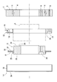
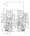
- FIG. 1 Longitudinal front view showing a bearing with a rotation sensor provided with a magnetic rotation sensor according to a first embodiment of the present invention
- FIG. 1 An exploded view of the bearing with a rotation sensor in FIG. 1
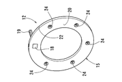
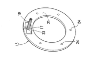
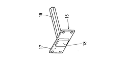
- the perspective view which shows one side part of the sensor holder of FIG. 2 The perspective view which shows the other side part of the sensor holder of FIG. 2
- Sectional drawing which shows the fitting process of the base part of an encoder of FIG. 2, and an outward flange part
- FIG. 1 A first embodiment as an example of the present invention will be described based on the attached drawings.
- the rotation sensor equipped bearing according to the first embodiment is shown in FIG.
- the disassembled state of the rotation sensor equipped bearing is shown in FIG.
- the rotation sensor-equipped bearing includes a magnetic rotation sensor 1 and a bearing 2.
- the magnetic rotation sensor 1 outputs a detection signal according to the rotation of the second member 4 relative to the first member 3.
- the bearing 2 has an outer ring forming the first member 3 and an inner ring forming the second member 4.
- the first member 3 is attached to a housing (not shown) of another device to which the rotation sensor bearing is attached.
- the second member 4 driven by the other device rotates relative to the stationary first member 3.
- the “axial direction” refers to a direction along the rotation axis of relative rotation between the first member 3 and the second member 4 (in design, coincident with the central axis of the bearing 2). Further, the direction perpendicular to the rotation axis is called “radial direction”, and the circumferential direction around the rotation axis is called “circumferential direction”.
- the bearing 2 is a cross roller bearing having a plurality of rollers 5 arranged orthogonally between the first member 3 and the second member 4.
- the plurality of rollers 5 are interposed between the V-groove-shaped track 6 formed on the inner periphery of the first member 3 and the V-groove-shaped track 7 formed on the outer periphery of the second member 4.
- the central axes of the rollers 5 adjacent to each other in the circumferential direction are orthogonal to each other, and the central axes of all the rollers 5 are inclined 45 ° with respect to the axial direction.
- the first member 3 and the second member 4 are each a bearing ring with a bolt hole.
- the bolt holes 8 formed in the first member 3 and the bolt holes 9 formed in the second member 4 have one side surface (left side in the drawing) of the corresponding first member 3 and the second member 4 in the axial direction.
- the corresponding first member 3 and second member 4 are axially penetrated from the portions 10 and 11.
- the bolt holes 8 and 9 are respectively formed at a plurality of locations at equal intervals in the circumferential direction.
- One side surface portion 10 of the first member 3 and one side surface portion 11 of the second member 4 are flat surfaces along the radial direction.
- the first member 3, the second member 4 and the roller 5 are each formed of steel.
- the magnetic rotation sensor 1 includes a sensor holder 12 attachable to one side surface 10 of the first member 3, an encoder 13 attachable to one side surface 11 of the second member 4, and a cap attachable to the sensor holder 12. And 14.
- the sensor holder 12 has an annular housing portion 15 axially overlapping the one side surface portion 10 of the first member 3, and a sensor substrate portion 16 fixed to the housing portion 15.
- the sensor substrate unit 16 has a substrate 17 and a magnetic sensor element 18 fixed to the substrate 17 as shown in FIGS. 1 and 3A to 3C.
- the substrate 17 is a circuit board.
- the magnetic sensor element 18 is an integrated circuit in which one or more sensor circuits for converting the change of the magnetic field into electric signals, a signal processing circuit for processing the electric signals of the sensor circuits and outputting detection signals, etc. ing.
- a cord 19 used for signal input / output with another device and power supply from another device is connected to the substrate 17.
- the housing portion 15 is continuous with the side surface 20 located at one end of the housing portion 15 in the axial direction, and the other side 21 located at the other end of the housing portion 15 in the axial direction. It has an annular outer periphery 22 and a substrate fixing portion 23 that accommodates the sensor substrate portion 16.
- One side surface 20 and the other side surface 21 of the housing portion 15 are flat surfaces along the radial direction.
- the other side surface 21 of the housing portion 15 is in axial contact with one side surface portion 10 of the first member 3 along the entire circumferential direction.
- a plurality of bolt holes 24 are formed in the housing portion 15 in an arrangement corresponding to the bolt holes 8 of the first member 3.
- the bolt holes 24 of the housing portion 15 axially penetrate the housing portion 15 from one side surface 20 of the housing portion 15.
- the substrate fixing portion 23 is recessed toward one side in the axial direction from the other side surface 21 of the housing portion 15 and has a shape opened at one center surface 20 of the housing portion 15 at one center surface 20 of the recessed portion.
- the substrate fixing portion 23 supports the substrate 17 of the sensor substrate portion 16 in a posture along the radial direction.
- the magnetic sensor element 18 of the sensor substrate portion 16 supported by the substrate fixing portion 23 is fitted in the opening of the substrate fixing portion 23.
- the package end face of the magnetic sensor element 18 is disposed to be flush with one side face 20 of the housing portion 15.
- the substrate 17 is screwed to the substrate fixing portion 23.
- the sensor substrate portion 16 may be sealed to the substrate fixing portion 23 by a mold of an insulating material.
- the encoder 13 has an annular base portion 25 axially overlapping the one side surface portion 11 of the second member 4, and a side of one side of the base portion 25 in the axial direction of the housing portion 15. It has an outwardly extending flange portion 26 and a magnetic track portion 27 opposed to the magnetic sensor element 18 with a magnetic gap g.
- the base portion 25 has a hollow shaft shape having another side surface 28 located at the other end of the base portion 25 in the axial direction and an end outer peripheral surface 29 fitted to the inner peripheral end of the second member 4. ing.
- the hollow hole of the base portion 25 can be used to pass the shaft, wiring, etc. of another device.
- the other side surface 28 of the base portion 25 is a flat surface along the radial direction.
- the other side surface 28 of the base portion 25 is in axial contact with one side surface portion 11 of the second member 4 along the entire circumferential direction.
- the end portion outer peripheral surface 29 of the base portion 25 is for disposing the encoder 13 coaxially with the second member 4 by fitting with the inner peripheral end portion of the second member 4.
- a plurality of bolt holes 30 are formed in an arrangement corresponding to the bolt holes 9 of the second member 4.
- the bolt hole 30 of the base portion 25 axially penetrates the base portion 25 from one side surface of the base portion 25 in the axial direction.
- the outward flange portion 26 is formed of an annular cored bar fitted on the outer periphery of the base portion 25.
- the outward flange portion 26 is a press-formed product with an L-shaped cross section having a cylindrical portion extending in the axial direction and a side plate portion extending in the radial direction from the end of the cylindrical portion.
- the outward facing flange portion 26 has one side surface 31 formed by a plate surface on one side in the axial direction of the side plate portion and another side surface 32 formed by a plate surface on the other side in the axial direction of the side plate portion.
- One side surface 31 and the other side surface 32 of the outward flange portion 26 are flat surfaces along the radial direction.
- the outer diameter of the outward flange portion 26 is smaller than the outer diameter of the housing portion 15.
- the magnetic track portion 27 is fixed to the outward flange portion 26.
- the magnetic track portion 27 has an annular shape having N and S poles alternately in the circumferential direction.
- the magnetic track portion 27 axially faces the magnetic sensor element 18 and the side surface 20 of the housing portion 15 with a gap therebetween.
- the gap is equal to the magnetic gap g all around the circumferential direction.
- the magnetic track portion 27 is made of a magnetic rubber material fixed to the other side surface 32 of the outward flange portion 26.
- the magnetic track portion 27 is formed by vulcanization on the other side surface 32 of the outward flange portion 26.
- the structure disclosed in Patent Document 1 suitable for rotational angle detection may be adopted.
- the base portion 25 is formed of sintered metal, and the outer periphery of the base portion 25 is The fitting surface with the outward facing flange portion 26 in the case, the other side surface 28 in contact with the one side surface portion 11 of the second member 4, the end outer peripheral surface 29 fitted in the inner peripheral end of the second member 4 etc.
- the sizing may be performed to appropriately improve the surface accuracy such as the cylindricity and the flatness, and the sway of the encoder 13 may be suppressed at low cost.
- the cap 14 has a cylindrical portion 33 attachable to the outer periphery 22 of the housing portion 15, and an inward flange portion 34 extending from the cylindrical portion 33 to one side of the outward flange portion 26 in the axial direction.
- the cylindrical portion 33 of the cap 14 is continuous along the entire circumferential direction and extends in the axial direction.
- the inward flange portion 34 extends in the radial direction from one end of the cylindrical portion 33 in the axial direction.
- the cap 14 is a press-formed product having an L-shaped cross section.
- the inner diameter of the cylindrical portion 33 of the cap 14 is larger than the outer diameter of the outward flange portion 26.
- the cylindrical portion 33 faces the outward flange portion 26 in the radial direction with a gap.
- the inner diameter of the inward flange portion 34 is less than half the outer diameter of the outward flange portion 26 and is larger than the outer diameter of the cylindrical portion of the outward flange portion 26.
- the inward flange portion 34 is axially opposed to the one side surface 31 of the outward flange portion 26 with a gap.
- the cap 14 and the encoder 13 form a labyrinth passage 35 passing between the inward flange portion 34 and the outward flange portion 26.
- the labyrinth passage 35 passes radially between the inward flange portion 34 and the side surface 31 of the outward flange portion 26 and extends axially between the inward flange portion 34 and the outer periphery of the cylindrical portion of the outward flange portion 26. I am passing by.
- the axial gap between the inward flange portion 34 and the one side surface 31 of the outward flange portion 26 is a radial gap between the inward flange portion 34 and the outer periphery of the cylindrical portion of the outward flange portion 26. Less than.
- the labyrinth passage 35 exerts a sealing effect to prevent foreign matter from the outside environment from invading the magnetic gap g (labyrinth seal).
- An axial gap of about the magnetic gap g is formed along the entire circumferential direction by one side surface 20 of the housing part 15, the magnetic sensor element 18, and the magnetic track part 27.
- the gap equivalent to the magnetic gap g is smaller than the radial gap between the cylindrical portion 33 of the cap 14 and the outward flange portion 26 and serves as a fluid passage having a high pressure compared to the labyrinth passage 35. Increase the sealing effect of 35.
- the cap 14, the outward flange portion 26, and the base portion 25 are each made of a magnetic material.
- a magnetic shield is constructed by the cap 14, the outward flange 26 and the base 25. Magnetic force lines coming from the outside enter the cap 14 and the base portion 25 and travel inside, so bypass the magnetic track portion 27, the magnetic gap g, and the magnetic sensor element 18. For this reason, in magnetic sensing by the magnetic sensor element 18, it becomes difficult to receive the influence of the magnetic field of external environment.
- the sensor holder mounting process will be described. This process is performed after the assembly of the sensor holder 12 is completed.
- the sensor holder 12 is fitted to the centering jig J1, and the centering jig J1 is fitted to the inner periphery of the second member 4 of the bearing 2 as shown in FIG.
- the sensor holder 12 and the first member 3 are coaxially disposed, and the other side surface 21 of the housing portion 15 of the sensor holder 12 and the one side surface portion 10 of the first member 3 are axially butted against each other.
- the first member 3 and the housing portion 15 of the sensor holder 12 are pivoted by bolts (not shown). Fix by screw fastening in the direction. By this fixing, the sensor holder 12 is attached to the one side surface portion 10 of the first member 3.
- the encoder mounting process is performed. This process is performed in a state where the assembly of the encoder 13 is completed, as shown in FIG.
- the encoder 13 and the second member 4 are coaxially arranged,
- the other side surface 28 of the base portion 25 and the one side surface portion 11 of the second member 4 are in the state of abutting in the axial direction.
- each bolt hole 30 of the encoder 13 and each bolt hole 9 of the second member 4 are used to axially move the second member 4 and the base portion 25 of the encoder 13 with bolts (not shown). Fix by screw fastening.
- the encoder 13 is attached to one side surface portion 11 of the second member 4, and the magnetic sensor element 18 and the magnetic track portion 27 face each other with the magnetic gap g.
- the cap mounting process is performed.
- the cap 14 and the sensor holder 12 are coaxially arranged by axially fitting the cylindrical portion 33 of the cap 14 and the outer periphery 22 of the housing 15 of the sensor holder 12.
- the cap 14 is fixed to the outer periphery 22 of the housing portion 15 by forcibly fitting the cylindrical portion 33 of the cap 14 and the outer periphery 22 of the housing portion 15.
- the cap 14 is attached to the sensor holder 12, and the labyrinth passage 35 is formed.
- the means for fixing the cap 14 to the outer periphery 22 of the housing portion 15 may be other means, for example, it may be adhesive.
- the outward flange portion 26 is attached to the base portion 25 by forcibly fitting the inner periphery of the cylindrical portion of the outward flange portion 26 and the outer periphery of the base portion 25.
- accurate magnetic gap g can be ensured by implementation of an encoder attachment process. For example, as shown in FIGS.
- a spacer jig (a shim having a plate thickness equivalent to a magnetic gap in which a fitting jig J2 having an outer portion equivalent to a second member fits with the base portion 25)
- the outward flange portion 26 and the outer periphery of the base portion 25 may be forcibly fitted in a state where the J3 is disposed between the magnetic track portion 27 and the fitting jig J2.
- the spacer jig J3 fitted to a half or more of the outer periphery of the base portion 25 is used, but the amount of the magnetic gap may be managed by only the fitting jig, for example, the fitting jig A jig in which the portion corresponding to J2 and the portion corresponding to the spacer jig J3 are integrally formed may be used.
- the sensor holder is assembled to the first member without using the fitting jig J2, and after the base portion is attached to the second member, the spacer jig J3 is held against the sensor holder and the outward flange portion is the base portion.
- the spacer jig J3 may be pulled out until it comes into contact with Alternatively, the sensor holder is assembled to the first member without using the fitting jig J2, and after the base portion is attached to the second member, the spacer jig J3 is held against the sensor holder and the outward flange portion is the base portion. The spacer jig J3 may be pulled out until it is pressed into contact with the
- the magnetic type rotation sensor 1 is as described above, and the magnetic type rotation sensor 1 can also rotate to a cross roller bearing, an actuator or the like where the distance between the inner peripheral end of the first member 3 and the outer peripheral end of the second member 4 is small
- the sensor 1 can be easily attached.
- the magnetic rotation sensor 1 itself can construct the labyrinth passage 35 and the magnetic shield, and protect the magnetic sensor element 18 and the like from foreign matters and magnetism in the external environment. For this reason, when the magnetic rotation sensor 1 is attached to a position affected by the external environment, for example, foreign matter or magnetism is attached to the robot joint even when attached to the output unit for the purpose of improving the positioning accuracy of the output unit of other devices. It can be made to be attachable even if the distance between the inner and outer peripheral ends of the two members 3 and 4 is short.
- the magnetic type rotation sensor 1 can narrow the distance between the side surface 20 of the housing portion 15 and the magnetic track portion 27 to about the magnetic gap g to further enhance the sealing effect.
- the magnetic rotation sensor 1 can adopt a general magnetic track portion fixed to the core metal by vulcanization molding, and the outward flange portion 26 composed of the core metal can be used as the base portion 25.
- the magnetic shield is constructed by the cap 14 and the outward flange portion 26 and the base portion 25 made of a magnetic material, and the magnetic shield of the external environment can be made insusceptible.
- the outward flange portion 26 is completely inclined relative to the rotation axis. It is difficult to install without it, and it is inevitable that a slight assembly error occurs. In addition, a slight error also occurs in the coaxiality of the sensor holder and the outward flange portion. In addition, a certain degree of error occurs in the magnetization accuracy of the magnetic track portion 27 itself. When highly accurate rotation detection is required, it is preferable to take measures for the adverse effect that the errors have on the detection accuracy in the magnetic rotation sensor after assembly.
- the first embodiment only one magnetic sensor element 18 is fixed to the housing portion 15 of the sensor holder 12, but a plurality of magnetic sensor elements are fixed to the housing portion, and the above-mentioned error is obtained using the outputs of these magnetic sensor elements. It is possible to suppress the influence of noise and to improve the detection accuracy.
- the second embodiment as an example is shown in FIG. In the following, only differences from the first embodiment will be described.
- the housing portion 40 of the sensor holder in the second embodiment has a pair of sensor windows 42 and 43 opened at one side surface 41 thereof.
- the pair of sensor windows 42 and 43 are arranged to be rotationally symmetrical by 180 ° in the circumferential direction.
- the pair of sensor windows 42 and 43 are portions that form the opening of the above-described substrate fixing portion.
- One magnetic sensor element 44, 45 is fitted in each sensor window 42, 43, respectively.
- the pair of magnetic sensor elements 44, 45 are each rectangular (see the magnetic sensor element 18 of FIG. 3C).
- that the magnetic sensor element is square means that the package portion is square.
- the package portion refers to an outer peripheral which wraps an electronic component which is a component of a magnetosensitive circuit, a signal processing circuit and the like, and is generally formed of a sealing material such as resin, metal or the like.
- the sensor window 42 has a shape having one corner in which the magnetic sensor element 44 can be arranged with reference to one corner of the magnetic sensor element 44.
- the positions of corresponding corners of the magnetic sensor element 44 and the sensor window 42 are indicated by a symbol a in FIG.
- the sensor window 43 has a shape that is rotationally symmetrical to the sensor window 42 in the circumferential direction by 180 °.
- the magnetic sensor element 45 has the same structure as the magnetic sensor element 44. Therefore, by bringing the two edges forming one corner of the position a of the sensor window 43 into contact with the two edges forming one corner of the position a of the magnetic sensor element 45, the arrangement of the magnetic sensor device 45 with respect to the housing portion 40 has a diameter It is fixed in the direction and the circumferential direction.
- One angle of the position a of the sensor window 43 and the magnetic sensor element 45 is 180 ° rotationally symmetric in the circumferential direction with the one angle of the position a of the sensor window 42 and the magnetic sensor element 44.
- the above-mentioned error based on the inclination or the coaxiality of the outward flange portion becomes a positive error from the true value in the detection of the magnetic sensor element 44 for converting the magnetic field of the magnetic track portion into the electric signal.
- a negative error occurs from the true value. Therefore, by averaging the detection value of the magnetic sensor element 44 and the detection value of the magnetic sensor element 45, it is possible to mutually absorb the above-mentioned errors and to improve the detection accuracy.
- the outputs of the magnetic sensor elements 44 and 45 are transmitted to the processing circuit (not shown) through the above-mentioned cords connected thereto, and the output data of the magnetic sensor elements 44 and 45 are averaged in the processing circuit It can be output as a detection signal.
- the processing circuit need not be mounted on the magnetic rotation sensor, and may be, for example, an arithmetic processing unit that controls an actuator.
- the pair of magnetic sensor elements 44 and 45 arranged in rotational symmetry of 180 ° are fixed to the housing portion 40, the pair of magnetic sensor elements 44, It becomes possible to average 45 detection values. If the averaging is performed, the adverse effect of the assembly error of the magnetic rotation sensor can be alleviated, and the detection accuracy of the physical quantity related to the rotational movement between the two members (the first member and the second member described above) can be improved.
- the pair of magnetic sensor elements 44 and 45 have a square shape, and the housing portion 40 has the pair of sensor windows 42 and 43 arranged in rotational symmetry of 180 °. Since the pair of sensor windows 42 and 43 have a shape having one angle at which the magnetic sensor elements 44 and 45 can be arranged with reference to one angle of the magnetic sensor elements 44 and 45, a general rectangular magnetic sensor element 44 and 45 can be employed, and the pair of magnetic sensor elements 44 and 45 can be accurately disposed in rotational symmetry of 180.degree.
- the housing portion 50 has a plurality of pairs of sensor windows 52 to 55 opened at one side surface 51 thereof. Magnetic sensor elements 56 to 59 are fitted in each of the sensor windows 52 to 55 one by one.
- the first pair of sensor windows 52 and 53 and the first pair of magnetic sensor elements 56 and 57 fitted thereto correspond to the second embodiment, and the magnetic sensor elements 56 and 57 are based on one corner of the position a. Is arranged.
- the second pair of sensor windows 54 and 55 are arranged in rotational symmetry 180 ° circumferentially in a phase different from that of the first pair of sensor windows 52 and 53.
- the second pair of sensor windows 54 and 55 and the second pair of magnetic sensor elements 58 and 59 fitted to these also correspond to the second embodiment, and the magnetic sensor elements 58 and 59 are based on one corner of the position b. Is arranged.
- the magnetic rotation sensor according to the third embodiment since the plurality of pairs of magnetic sensor elements 56 to 59 disposed at 180 ° rotational symmetry in different phases with each other are fixed to the housing portion 50 It is possible to perform averaging using the detection values of the magnetic sensor elements 56 to 59, thereby further improving the detection accuracy of the physical quantity related to the rotational movement between the two members.
- FIG. 1 An example in the case of using the magnetic rotation sensor which concerns on the above-mentioned embodiment as position detection of the output part of an actuator is shown in FIG.
- the actuator includes a speed reduction mechanism 60 and an annular mounting member 61.
- a plurality of screw holes 61 a are formed in the outer peripheral portion of the mounting member 61.
- the actuator is fixed in another apparatus such as a robot arm using the screw holes 61a.
- the reduction gear mechanism 60 As the reduction gear mechanism 60, a wave gear device using a differential of an ellipse and a perfect circle is illustrated.
- the reduction mechanism 60 includes a wave generator 64 coupled rotatably to the main shaft 63 of the hollow drive motor 62, a circular spline 65 disposed radially outward of the wave generator 64, a wave generator 64 and a circular spline 65. And a flex spline 66 in which the large diameter portion is sandwiched therebetween.
- the circular spline 65 is an annular part provided with teeth on its inner periphery.
- the circular spline 65 is fixed in the apparatus via the mounting member 61.
- the circular spline 65 is arranged to be adjacent to the mounting member 61 in the axial direction.
- the flange portion of the drive motor 62 and the fixed outer ring 68 of the reverse input blocking mechanism 67 sandwich the circular spline 65 and the mounting member 61 in the axial direction, and the flange portion and the fixed outer ring 68 are bolted together to drive the mounting member 61
- the motor 62 and the fixed outer ring 68 are integrated.
- the wave generator 64 is obtained by fitting and fixing an inner ring of a ball bearing 64b to the outer periphery of a cam 64a having an elliptical radial cross section.
- the wave generator 64 is connected to the main shaft 63 of the drive motor 62 via a hollow detent member 69.
- the wave generator 64 is an input side member of the reduction mechanism 60.
- the flex spline 66 is a thin cup-shaped component formed of a metal elastic body, and has teeth on the outer periphery of the large diameter portion that mesh with the teeth on the inner periphery of the circular spline 65.
- the flex spline 66 is rotatably coupled at its small diameter portion (one end portion) to an input pin 70 which is an input portion of the reverse input blocking mechanism 67.
- the flex spline 66 is an output side member of the reduction mechanism 60.
- the wave generator 64 When the wave generator 64 is rotated by the drive of the drive motor 62, the inner periphery of the large diameter portion of the flex spline 66 is pressed by the outer ring of the ball bearing 64b. Along with this, the flex spline 66 is elastically deformed to change the meshing position with the circular spline 65, and thus, the difference in the number of teeth with the circular spline 65 is rotated. The differential rotation is transmitted to the input pin 70 of the reverse input blocking mechanism 67.
- a cylindrical guide member 71 is fixed on the inner periphery of the flange portion of the drive motor 62 at a position in sliding contact with the end face of the large diameter portion of the flex spline 66.
- the cam member 73 serves as an output portion of the reverse input blocking mechanism 67.
- the input pin 70 serves as an input portion of the reverse input blocking mechanism 67.
- the cam member 73 is provided with an engagement hole 73a.
- a sleeve 74 is fitted and fixed to the outer periphery on the tip side of the input pin 70.
- the sleeve 74 is inserted into the engagement hole 73a with a circumferential gap.
- the lock release piece 72 is provided with an engagement hole 72a.
- the central portion of the input pin 70 is inserted into the engagement hole 72a with a circumferential gap.
- a circumferential gap between the engagement hole 72 a of the unlocking piece 72 and the central portion of the input pin 70 is narrower than a circumferential gap between the engagement hole 73 a of the cam member 73 and the sleeve 74.
- a bearing 2 is provided between the cam member 73 described above and the encoder 13 connected to the driven member.
- the first member 3, which is the outer ring of the bearing 2 is bolted to the fixed outer ring 68 of the reverse input blocking mechanism 67.
- a second member 4 which is an inner ring of the bearing 2 is bolted to rotate integrally with the cam member 73 and the encoder 13.
- the rotational speed and rotational position of the encoder 13 that rotates integrally with the cam member 73 are detected by the magnetic sensor element 56 or the like arranged as in the third embodiment.
- the arithmetic processing unit (not shown) calculates the difference between the target rotational speed and the target position based on the detection signal obtained by averaging the detection values of the magnetic sensor element 56 etc., and drives according to the difference.
- the motor 62 is controlled. Therefore, the accuracy of the rotational position and the rotational speed can be improved.
- the magnetic rotation sensor according to the third embodiment detects the rotation of the cam member 73 (output unit), so that the positioning accuracy as the actuator can be improved.
- this actuator does not require sensor protection at the contact seal by adopting a magnetic rotation sensor that can ignore the influence of external light and dust, and in turn increases the structure size and seal in order to obtain the mounting strength of the seal. The torque loss due to the binding force can also be eliminated.
- the external magnetic field used as noise it is possible for the external magnetic field used as noise to interrupt
- the magnetic rotation sensor of the third embodiment is adopted, but it is also possible to adopt the magnetic rotation sensor of the first or second embodiment.
Landscapes
- Engineering & Computer Science (AREA)
- General Engineering & Computer Science (AREA)
- Mechanical Engineering (AREA)
- Physics & Mathematics (AREA)
- General Physics & Mathematics (AREA)
Abstract
第一部材(3)の一側面部(10)に取り付けるセンサホルダ(12)は、第一部材(3)の一側面部(10)に軸方向に重なる環状のハウジング部(15)にセンサ基板部(16)を固定したものとする。第二部材(4)の一側面部(11)に取り付けるエンコーダ(13)は、第二部材(4)の一側面部(11)に軸方向に重なる環状のベース部(25)からハウジング部(15)の側方へ延びる外向きフランジ部(26)と、磁気トラック部(27)とを有する。キャップ(14)の筒部(33)をハウジング部(15)の外周(22)に取り付けると、キャップ(14)の内向きフランジ部(34)が外向きフランジ部(26)の側方に位置し、キャップ(14)とエンコーダ(13)とによってラビリンス通路(35)が形成される。
Description
この発明は、第一部材に対する第二部材の相対的な回転を検出する磁気式回転センサ、その磁気式回転センサを軸受に取り付けた回転センサ付き軸受、その磁気式回転センサを備えるアクチュエータ、及びその磁気式回転センサの取付け方法に関する。
磁気式回転センサは、一般に、第一部材側に固定する磁気センサ素子と、第二部材側に固定する磁気トラックとを有する。磁気トラックと磁気センサ素子は、磁気ギャップをおいて対向するように配置される。第一部材と第二部材との間の相対回転に応じて、磁気センサ素子で感知される磁気トラックの磁界が変化し、磁気センサ素子は、その変化を検出する。その検出信号に基づき、回転角度、回転量、回転速度等、回転運動に関する物理量が測定される(例えば、特許文献1)。
第一部材、第二部材に磁気式回転センサを取り付ける構造として、嵌合構造が広く採用されている(例えば、特許文献2)。
特許文献2の磁気式回転センサは、第一部材に固定されるセンサホルダと、第二部材に固定されるエンコーダとを備える。センサホルダは、環状カバー部と、環状カバー部の内側面に嵌合された環状のハウジング部と、ハウジング部に固定されたセンサ基板部とを有する。センサ基板部は、回路基板と、その回路基板に固定された磁気センサ素子とを有する。エンコーダは、環状の芯金部と、芯金部の外周に固着された磁性ゴム材製の磁気トラック部とを有する。第一部材は軸受の外輪からなり、第二部材は軸受の内輪からなる。先ず、エンコーダの芯金部の内周端部を第二部材の外周一端部に嵌合することにより、第二部材に対して磁気トラック部が所定位置に配置される。次に、センサホルダの環状カバー部の外周端部を第一部材の内周一端部に嵌合することにより、第一部材、磁気トラック部に対して磁気センサ素子が所定位置に配置され、また、センサホルダとエンコーダとの間にラビリンス通路が形成される。
アクチュエータ等の出力部はアクチュエータの外部に位置するため、磁気式回転センサで出力部の回転検出を行う場合には、外部環境の影響を受ける恐れがある。
特許文献2の磁気式回転センサは、異物侵入をラビリンス通路のシール効果で防止できるので、外部環境の影響を受け難いが、環状カバー部の外周端部を第一部材(外輪)の内周端部に嵌合し、芯金部の内周端部を第二部材(内輪)の外周端部に嵌合する取り付け構造となっている。このため、第一部材の内周端部と第二部材の外周端部との間には、環状カバー部の端部及び芯金部の端部を配置できる距離が必要である。ところが、ロボット関節のアクチュエータの出力に使用されるクロスローラ軸受のように、外輪の内周端部と内輪の外周端部との間の距離が非常に短い場合、特許文献2の磁気式回転センサを取り付けることができない問題がある。
上述の背景に鑑み、この発明が解決しようとする課題は、外部環境の影響を受ける位置に取り付ける場合でもその影響を受け難く、かつ二部材の内外周端部間の距離が短くとも取り付け可能な構造の磁気式回転センサを提供することである。
上記の課題を達成するため、この発明は、第一部材の軸方向一方側の一側面部に取り付け可能なセンサホルダと、前記第一部材に対して相対的に回転する第二部材の軸方向一方側の一側面部に取り付け可能なエンコーダと、前記センサホルダに取り付け可能なキャップとを備え、前記センサホルダが、前記第一部材の一側面部に軸方向に重なる環状のハウジング部と、前記ハウジング部に固定されたセンサ基板部とを有し、前記センサ基板部が、基板と、前記基板に固定された磁気センサ素子とを有し、前記エンコーダが、前記第二部材の一側面部に軸方向に重なる環状のベース部と、前記ベース部から前記ハウジング部の軸方向一方側の側方へ延びる外向きフランジ部と、前記磁気センサ素子と磁気ギャップをおいて対向する磁気トラック部とを有し、前記キャップが、前記ハウジング部の外周に取り付け可能な筒部と、前記筒部から前記外向きフランジ部の軸方向一方側の側方へ延びる内向きフランジ部とを有し、前記キャップと前記エンコーダとによって、前記内向きフランジ部と前記外向きフランジ部間を通るラビリンス通路が形成される構成を採用したものである。
上記構成によれば、センサホルダ、エンコーダの取付け先が対応の第一部材、第二部材の一側面部であり、キャップの取付け先がセンサホルダであるから、これらセンサホルダ、エンコーダ、キャップを第一部材の内周端部と第二部材の外周端部間に配置せずに済み、これら二部材の内外周端部間の距離が短くとも磁気式回転センサを取り付けることが可能である。さらに、これらセンサホルダ、エンコーダを対応の第一部材、第二部材の一側面部に取り付け、キャップの筒部をセンサホルダのハウジング部の外周に取り付けると、キャップの内向きフランジ部とエンコーダの外向きフランジ部との間を通るラビリンス通路が形成されるので、外部環境の影響を受け難い構造となる。
例えば、前記磁気トラック部が、前記外向きフランジ部に固着されており、前記磁気センサ素子が、前記磁気トラック部と軸方向に対向する前記ハウジング部の一側面と同一面を成すように配置されているとよい。このようにすると、ハウジング部の一側面と、磁気トラック部間の距離を磁気ギャップ程度に狭くし、シール効果をより高めることができる。
また、前記外向きフランジ部が、前記ベース部の外周に嵌る環状の芯金からなり、前記磁気トラック部が、前記外向きフランジ部に固着された磁性ゴム材料からなり、前記キャップ、前記外向きフランジ部及び前記ベース部が、それぞれ磁性材からなるものでもよい。このようにすると、芯金に加硫成型で固着した一般的な磁気トラック部を採用することができ、また、キャップと、外向きフランジ部及びベース部により磁気シールドを構築し、外部環境の磁界の影響を受け難くすることができる。
180°回転対称に配置された対の前記磁気センサ素子が前記ハウジング部に固定されているとよい。このようにすると、対の磁気センサ素子の検出値を平均化することが可能になる。その平均化を行えば、二部材間の回転運動に関する物理量の検出精度を向上させることができる。
互いに異なる位相で180°回転対称に配置された複数対の前記磁気センサ素子が前記ハウジング部に固定されているとよい。このようにすると、各対の磁気センサ素子の検出値を用いて平均化を行うことが可能になる。ひいては、二部材間の回転運動に関する物理量の検出精度をより向上させることができる。
前記対の磁気センサ素子が、それぞれ四角形状であり、前記ハウジング部が、180°回転対称に配置された対のセンサ窓を有し、前記対のセンサ窓が、それぞれ前記磁気センサ素子の一角を基準として当該磁気センサ素子を配置可能な一角を有する形状であることがより好ましい。このようにすると、一般的な四角形状の磁気センサ素子を採用し、その一角を利用して対の磁気センサ素子を180°回転対称に正確に配置することができる。
この発明に係る磁気式回転センサと、軸受とを備え、前記軸受が、前記第一部材を構成する外輪と、前記第二部材を構成する内輪とを有する回転センサ付き軸受に構成してもよい。
例えば、前記軸受が、前記第一部材と前記第二部材との間に直交配列された複数のローラを有するクロスローラ軸受からなる。
この発明に係る磁気式回転センサが出力部の回転を検出するように構成されたアクチュエータとしてもよい。このようにすると、アクチュエータの位置決め精度の向上を図ることができる。また、光式回転センサの場合、外部光やほこりなどの侵入を防止するため、接触シールの使用が必要になり、シールの緊縛力に対応のシールの取付け強度を得るために構造が大きくなると共にトルクロスもある。これに対して、磁気式回転センサを採用すれば、ほこり等の影響を無視できるので、接触シールを不要とし、トルクロスも無くすことが可能になる。
この発明に係る磁気式回転センサの取付け方法としては、例えば、前記第一部材と前記センサホルダのハウジング部とを軸方向にねじ締結するセンサホルダ取付け工程と、前記センサホルダ取付け工程後、前記第二部材と前記エンコーダのベース部とを軸方向にねじ締結するエンコーダ取付け工程と、前記エンコーダ取付け工程後、前記キャップの筒部と前記センサホルダのハウジング部の外周とを嵌合するキャップ取付け工程と、を有する磁気式回転センサの取付け方法を採用することができる。
この発明は、上記構成の採用により、外部環境の影響を受ける位置に取り付ける場合でもその影響を受け難く、かつ二部材の内外周端部間の距離が短くとも取り付け可能な構造の磁気式回転センサを提供することができる。
この発明の一例としての第一実施形態を添付図面に基づいて説明する。第一実施形態に係る回転センサ付き軸受を図1に示す。この回転センサ付き軸受の分解状態を図2に示す。
この回転センサ付き軸受は、磁気式回転センサ1と、軸受2とを備える。
磁気式回転センサ1は、第一部材3に対する相対的な第二部材4の回転に応じた検出信号を出力するものである。
軸受2は、第一部材3を構成する外輪と、第二部材4を構成する内輪とを有する。第一部材3は、この回転センサ付き軸受の取り付け相手となる他装置のハウジング(図示省略)に取り付けられる。他装置に駆動される第二部材4が、静止する第一部材3に対して相対的に回転することになる。
以下、「軸方向」は、第一部材3と第二部材4の相対回転の回転軸線(設計上、軸受2の軸受中心軸に一致)に沿った方向のことをいう。また、その回転軸線に対して直角な方向のことを「径方向」といい、その回転軸線回りの円周方向のことを「周方向」という。
軸受2は、第一部材3と第二部材4との間に直交配列された複数のローラ5を有するクロスローラ軸受からなる。複数のローラ5は、第一部材3の内周に形成されたV溝状の軌道6と、第二部材4の外周に形成されたV溝状の軌道7との間に介在する。周方向に隣り合うローラ5同士の中心軸は、互いに直交する向きであり、いずれのローラ5の中心軸も軸方向に対して45°傾斜している。
第一部材3、第二部材4は、それぞれボルト穴付き軌道輪になっている。第一部材3に形成されたボルト穴8、第二部材4に形成されたボルト穴9は、それぞれ対応の第一部材3、第二部材4の軸方向一方側(図中左側)の一側面部10、11から対応の第一部材3、第二部材4を軸方向に貫通している。ボルト穴8、9は、それぞれ周方向に均等な間隔で複数箇所に形成されている。第一部材3の一側面部10、第二部材4の一側面部11は、それぞれ径方向に沿った平坦面となっている。
第一部材3、第二部材4、ローラ5は、それぞれ鋼によって形成されている。
磁気式回転センサ1は、第一部材3の一側面部10に取り付け可能なセンサホルダ12と、第二部材4の一側面部11に取り付け可能なエンコーダ13と、センサホルダ12に取り付け可能なキャップ14とを備える。
センサホルダ12は、第一部材3の一側面部10に軸方向に重なる環状のハウジング部15と、ハウジング部15に固定されたセンサ基板部16とを有する。
センサ基板部16は、図1、図3A~図3Cに示すように、基板17と、基板17に固定された磁気センサ素子18とを有する。基板17は、回路基板になっている。磁気センサ素子18は、磁界の変化を電気信号に変換する1つ以上のセンサ回路、センサ回路の電気信号を処理して検出信号を出力する信号処理回路等を1つにまとめた集積回路になっている。基板17には、他装置との間の信号入出力、他装置からの電源供給に用いるコード19が接続されている。
ハウジング部15は、ハウジング部15の軸方向一方側の端部に位置する一側面20と、ハウジング部15の軸方向他方側の端部に位置する他側面21と、周方向全周に連続する円環状の外周22と、センサ基板部16を収容する基板固定部23とを有する。
ハウジング部15の一側面20、他側面21は、それぞれ径方向に沿った平坦面となっている。ハウジング部15の他側面21は、第一部材3の一側面部10と周方向全周で軸方向に接する。
ハウジング部15には、第一部材3のボルト穴8に対応の配置で複数のボルト穴24が形成されている。ハウジング部15のボルト穴24は、ハウジング部15の一側面20からハウジング部15を軸方向に貫通している。
基板固定部23は、ハウジング部15の他側面21から軸方向一方側へ凹み、その凹底面の中央位置でハウジング部15の一側面20に開口した形状になっている。基板固定部23は、センサ基板部16の基板17を径方向に沿う姿勢に支持する。基板固定部23に支持されたセンサ基板部16の磁気センサ素子18は、基板固定部23の開口に嵌っている。この磁気センサ素子18のパッケージ端面は、ハウジング部15の一側面20と同一面を成すように配置されている。基板17は、基板固定部23にねじ止めされている。絶縁材のモールドでセンサ基板部16を基板固定部23に封止してもよい。
図1、図2に示すように、エンコーダ13は、第二部材4の一側面部11に軸方向に重なる環状のベース部25と、ベース部25からハウジング部15の軸方向一方側の側方へ延びる外向きフランジ部26と、磁気センサ素子18と磁気ギャップgをおいて対向する磁気トラック部27とを有する。
ベース部25は、ベース部25の軸方向他方側の端部に位置する他側面28と、第二部材4の内周端部に嵌合する端部外周面29とを有する中空軸状になっている。ベース部25の中空穴は、他装置の軸、配線等を通すために利用することができる。
ベース部25の他側面28は、径方向に沿った平坦面となっている。ベース部25の他側面28は、第二部材4の一側面部11と周方向全周で軸方向に接する。ベース部25の端部外周面29は、第二部材4の内周端部との嵌合により、エンコーダ13を第二部材4と同軸に配置するためのものである。
ベース部25には、第二部材4のボルト穴9に対応の配置で複数のボルト穴30が形成されている。ベース部25のボルト穴30は、ベース部25の軸方向一方側の一側面からベース部25を軸方向に貫通している。
外向きフランジ部26は、ベース部25の外周に嵌る環状の芯金からなる。外向きフランジ部26は、軸方向に延びる円筒部と、この円筒部の端から径方向に延びる側板部とを有する断面L形のプレス成形品になっている。外向きフランジ部26は、その側板部の軸方向一方側の板面からなる一側面31と、その側板部の軸方向他方側の板面からなる他側面32とを有する。
外向きフランジ部26の一側面31、他側面32は、それぞれ径方向に沿った平坦面となっている。外向きフランジ部26の外径は、ハウジング部15の外径よりも小さい。
磁気トラック部27は、外向きフランジ部26に固着されている。磁気トラック部27は、周方向に交互にN極とS極とを有する円環状になっている。磁気トラック部27は、磁気センサ素子18及びハウジング部15の一側面20との間に隙間をおいて軸方向に対向する。その隙間は、周方向全周で磁気ギャップgと同等である。第一部材3に対して第二部材4が回転すると、磁気センサ素子18によって感磁される磁気トラック部27の磁界が当該回転に応じて変化し、磁気センサ素子18が当該回転に応じた出力信号を生成する。
磁気トラック部27は、外向きフランジ部26の他側面32に固着された磁性ゴム材料からなる。磁気トラック部27は、外向きフランジ部26の他側面32に加硫成型されている。
上述のようなエンコーダ13として、回転角度検出に好適な特許文献1に開示された構造を採用してもよく、具体的には、ベース部25を焼結金属で形成し、ベース部25の外周における外向きフランジ部26との嵌め合い面、第二部材4の一側面部11に当接する他側面28、第二部材4の内周端部に嵌合する端部外周面29等を適宜にサイジングして、円筒度、平面度等の表面精度を適宜に向上させ、エンコーダ13の振れ回りを低コストに抑制してもよい。
キャップ14は、ハウジング部15の外周22に取り付け可能な筒部33と、筒部33から外向きフランジ部26の軸方向一方側の側方へ延びる内向きフランジ部34とを有する。
キャップ14の筒部33は、周方向全周に連続し、軸方向に延びている。内向きフランジ部34は、筒部33の軸方向一方側の端から径方向に延びている。キャップ14は、断面L形のプレス成形品になっている。
キャップ14の筒部33の内径は、外向きフランジ部26の外径よりも大きい。筒部33は、外向きフランジ部26との間に隙間をおいて径方向に対向する。内向きフランジ部34の内径は、外向きフランジ部26の外径の半分未満であり、外向きフランジ部26の円筒部の外径よりも大きい。内向きフランジ部34は、外向きフランジ部26の一側面31との間に隙間をおいて軸方向に対向する。
キャップ14とエンコーダ13とによって、内向きフランジ部34と外向きフランジ部26間を通るラビリンス通路35が形成される。ラビリンス通路35は、内向きフランジ部34と外向きフランジ部26の一側面31との間を径方向に通り、内向きフランジ部34と外向きフランジ部26の円筒部外周との間を軸方向に通っている。内向きフランジ部34と、外向きフランジ部26の一側面31との間の軸方向の隙間は、内向きフランジ部34と、外向きフランジ部26の円筒部外周との間の径方向の隙間よりも小さい。ラビリンス通路35は、外部環境からの異物が磁気ギャップgへ侵入することを防ぐシール効果を奏する(ラビリンスシール)。
ハウジング部15の一側面20及び磁気センサ素子18と、磁気トラック部27とによって、磁気ギャップg程度の軸方向の隙間が周方向全周に形成される。この磁気ギャップg相当の隙間は、キャップ14の筒部33と外向きフランジ部26との間の径方向の隙間よりも小さく、ラビリンス通路35に比して高圧の流体通路となるので、ラビリンス通路35のシール効果を高める。
キャップ14、外向きフランジ部26及びベース部25は、それぞれ磁性材からなる。キャップ14と、外向きフランジ部26及びベース部25により磁気シールドが構築される。外部から到来する磁力線は、キャップ14やベース部25に入り、その内部を進むので、磁気トラック部27、磁気ギャップg、磁気センサ素子18を迂回する。このため、磁気センサ素子18による感磁において外部環境の磁界の影響が受け難くなる。
磁気式回転センサ1を第一部材3と第二部材4に取り付ける方法を説明する。
先ず、センサホルダ取付け工程について説明する。この工程は、センサホルダ12の組み立てを終えた状態で実施する。図2に示すように、センサホルダ12を芯出し治具J1に嵌合し、芯出し治具J1と軸受2の第二部材4の内周とを嵌合することにより、図1に示すようにセンサホルダ12と第一部材3とを同軸に配置して、センサホルダ12のハウジング部15の他側面21と第一部材3の一側面部10とを軸方向に突き当てた状態とする。この突き当て状態で、センサホルダ12の各ボルト穴24、第一部材3の各ボルト穴8を用いて、第一部材3とセンサホルダ12のハウジング部15とを、ボルト(図示省略)で軸方向にねじ締結することにより、固定する。この固定により、センサホルダ12が第一部材3の一側面部10に取り付けられた状態となる。
センサホルダ取付け工程後、エンコーダ取付け工程を実施する。この工程は、図2に示すように、エンコーダ13の組み立てを終えた状態で行う。エンコーダ13の端部外周29と、第二部材4の内周端部とを図1に示すように嵌合することにより、エンコーダ13と第二部材4とを同軸に配置して、エンコーダ13のベース部25の他側面28と第二部材4の一側面部11とを軸方向に突き当てた状態とする。この突き当て状態で、エンコーダ13の各ボルト穴30、第二部材4の各ボルト穴9を用いて、第二部材4とエンコーダ13のベース部25とを、ボルト(図示省略)で軸方向にねじ締結することにより、固定する。この固定により、エンコーダ13が第二部材4の一側面部11に取り付けられた状態となり、磁気センサ素子18と磁気トラック部27とが磁気ギャップgをおいて対向する。
エンコーダ取付け工程後、キャップ取付け工程を実施する。この工程では、キャップ14の筒部33と、センサホルダ12のハウジング部15の外周22とを軸方向に嵌合することにより、キャップ14とセンサホルダ12とを同軸に配置する。ここで、キャップ14の筒部33とハウジング部15の外周22とを強制的に嵌合することにより、キャップ14をハウジング部15の外周22に固定する。これにより、キャップ14がセンサホルダ12に取り付けられた状態となり、ラビリンス通路35が形成される。なお、キャップ14をハウジング部15の外周22に固定する手段は、他の手段でもよく、例えば、接着でよい。
上述のエンコーダ13の組み立て工程では、外向きフランジ部26の円筒部内周とベース部25の外周とを強制的に嵌合することにより、外向きフランジ部26がベース部25に取り付けられる。この際、治具を用いて外向きフランジ部26の固定位置を正確に管理しておけば、エンコーダ取付け工程の実施により、正確な磁気ギャップgを確保することができる。例えば、図4A、図4Bに示すように、第二部材相当の外形部を有する嵌合治具J2とベース部25とが嵌合し、かつ磁気ギャップ相当の板厚を有するスペーサ治具(シム)J3が磁気トラック部27と嵌合治具J2との間に配置された状態で、外向きフランジ部26とベース部25の外周とを強制的に嵌合すればよい。なお、図示例では、ベース部25の外周の半周以上に嵌合するスペーサ治具J3を用いたが、嵌合治具のみで磁気ギャップの量を管理してもよく、例えば、嵌合治具J2相当部とスペーサ治具J3相当部とが一体に形成された治具を用いてもよい。又は、嵌合治具J2を用いず第一部材にセンサホルダを組込み、第二部材にベース部を取付け後にセンサホルダにスペーサ治具J3を当てて外向きフランジ部をベース部にスペーサ治具J3に当接するまで圧入し、その後スペーサ治具J3を引抜いても良い。又は、嵌合治具J2を用いず第一部材にセンサホルダを組込み、第二部材にベース部を取付け後にセンサホルダにスペーサ治具J3を当てて外向きフランジ部をベース部にスペーサ治具J3に当接するまで圧入し、その後、スペーサ治具J3を引抜いても良い。
磁気式回転センサ1は、上述のようなものであり、第一部材3の内周端部と第二部材4の外周端部間の距離が僅かなクロスローラ軸受、アクチュエータ等へも磁気式回転センサ1を容易に取り付けることができる。また、磁気式回転センサ1は、これ自体でラビリンス通路35や磁気シールドを構築し、外部環境の異物や磁気に対して磁気センサ素子18等を防護することができる。このため、磁気式回転センサ1は、外部環境の影響を受ける位置に取り付ける場合、例えば、ロボット関節において、他装置の出力部の位置決め精度の向上を目的で出力部に取り付ける場合でもその異物や磁気の影響を受け難く、かつ二部材3、4の内外周端部間の距離が短くとも取り付け可能なものにすることができる。
また、磁気式回転センサ1は、ハウジング部15の一側面20と、磁気トラック部27間の距離を磁気ギャップg程度に狭くし、シール効果をより高めることができる。
また、磁気式回転センサ1は、芯金に加硫成型で固着した一般的な磁気トラック部を採用することができ、また、その芯金で構成された外向きフランジ部26をベース部25に嵌合することにより、キャップ14と、磁性材製の外向きフランジ部26及びベース部25により磁気シールドを構築し、外部環境の磁界の影響を受け難くすることができる。
前述のように、外向きフランジ部26をハウジング部15に嵌合冶具J2とスペーサ冶具J3を使用して磁気式回転センサを組み立てるとしても、外向きフランジ部26を回転軸線に対して完全に傾き無く取り付けることは難しく、僅かに組立誤差が生じることは不可避である。また、センサホルダと外向きフランジ部の同軸度にも僅かな誤差が生じる。また、磁気トラック部27自体の着磁精度もある程度の誤差が生じる。高精度の回転検出が必要な場合には、組立後の磁気式回転センサにおいて、それら誤差が検出精度に及ぼす悪影響について対応策を取ることが好ましい。第一実施形態では、磁気センサ素子18を1個だけセンサホルダ12のハウジング部15に固定したが、ハウジング部に複数の磁気センサ素子を固定し、それら磁気センサ素子の出力を用いて前述の誤差の影響を抑え、検出精度の向上を図ることが可能である。その一例としての第二実施形態を図5に示す。なお、以下では、第一実施形態との相違点を述べるに留める。
第二実施形態におけるセンサホルダのハウジング部40は、その一側面41に開口する一対のセンサ窓42,43を有する。一対のセンサ窓42,43は、周方向に180°回転対称に配置されている。一対のセンサ窓42,43は、それぞれ前述の基板固定部の開口を成す部位である。各センサ窓42,43には、磁気センサ素子44,45が1個ずつ嵌っている。
一対の磁気センサ素子44,45は、それぞれ四角形状である(図3Cの磁気センサ素子18を参照のこと)。ここで、磁気センサ素子が四角形状であるとは、パッケージ部が四角形状であることを意味する。パッケージ部は、感磁回路、信号処理回路等の構成要素である電子部品を包む外周器のことをいい、一般に、樹脂、金属等の封止材によって形成されている。
センサ窓42は、磁気センサ素子44の四角形状の一角を基準として磁気センサ素子44を配置可能な一角を有する形状である。その磁気センサ素子44とセンサ窓42の対応の一角の位置を図5中に符号aで示す。センサ窓42の位置aの一角を成す二辺と、磁気センサ素子44の位置aの一角を成す二辺とを接触させることにより、ハウジング部40に対する磁気センサ素子44の配置が径方向及び周方向に関して一定に定められる。
センサ窓43は、センサ窓42と周方向に180°回転対称の形状である。磁気センサ素子45は、磁気センサ素子44と同一構造のものである。したがって、センサ窓43の位置aの一角を成す二辺縁と、磁気センサ素子45の位置aの一角を成す二辺縁とを接触させることにより、ハウジング部40に対する磁気センサ素子45の配置が径方向及び周方向に関して一定に定められる。センサ窓43及び磁気センサ素子45の位置aの一角は、センサ窓42及び磁気センサ素子44の位置aの一角と周方向に180°回転対称の関係にあるから、それら位置aを基準として一対のセンサ窓42,43に一対の磁気センサ素子44,45を配置することにより、一対の磁気センサ素子44,45が、周方向に180°回転対称に正確に配置される。
前述の外向きフランジ部の傾きや同軸度に基づく誤差は、前述の磁気トラック部の磁界を電気信号に変換する磁気センサ素子44の検出において、真の値から正の誤差となり、周方向に180°反対側の位置で前述の磁気トラック部の磁界を電気信号に変換する磁気センサ素子45の検出において、真の値から負の誤差となる。したがって、磁気センサ素子44の検出値と磁気センサ素子45の検出値を平均化すれば、前述の誤差を互いに吸収して検出精度の向上を図ることが可能である。なお、磁気センサ素子44,45の各出力は、それぞれに接続された前述のコードを経て処理回路(図示省略)に送信し、その処理回路において磁気センサ素子44,45の出力データを平均化して検出信号として出力することができる。その処理回路は、磁気式回転センサに搭載する必要はなく、例えば、アクチュエータの制御を行なう演算処理装置を処理回路としてもよい。
このように、第二実施形態に係る磁気式回転センサは、180°回転対称に配置された対の磁気センサ素子44,45がハウジング部40に固定されているので、対の磁気センサ素子44,45の検出値を平均化することが可能になる。その平均化を行えば、磁気式回転センサの組立誤差の悪影響を緩和し、二部材(前述の第一部材と第二部材)間の回転運動に関する物理量の検出精度を向上させることができる。
また、第二実施形態に係る磁気式回転センサは、対の磁気センサ素子44,45がそれぞれ四角形状であり、ハウジング部40が180°回転対称に配置された対のセンサ窓42,43を有し、対のセンサ窓42,43がそれぞれ磁気センサ素子44,45の一角を基準として当該磁気センサ素子44,45を配置可能な一角を有する形状であるので、一般的な四角形状の磁気センサ素子44,45を採用し、その一角を利用して対の磁気センサ素子44,45を180°回転対称に正確に配置することができる。
複数対の磁気センサ素子をハウジング部に固定して更に検出精度の向上を図ることも可能である。その一例としての第三実施形態を図6に示す。なお、ここでは、第二実施形態からの更なる変更点を述べるに留める。
第三実施形態に係るハウジング部50は、その一側面51に開口する複数対のセンサ窓52~55を有する。各センサ窓52~55には、磁気センサ素子56~59が1個ずつ嵌っている。
第一対のセンサ窓52,53と、これらに嵌る第一対の磁気センサ素子56,57は、第二実施形態に相当するものであり、位置aの一角を基準として磁気センサ素子56,57が配置されている。
第二対のセンサ窓54,55は、第一対のセンサ窓52,53とは異なる位相で周方向に180°回転対称に配置されている。第二対のセンサ窓54,55と、これらに嵌る第二対の磁気センサ素子58,59も、第二実施形態に相当するものであり、位置bの一角を基準として磁気センサ素子58,59が配置されている。
このように、第三実施形態に係る磁気式回転センサは、互いに異なる位相で180°回転対称に配置された複数対の磁気センサ素子56~59がハウジング部50に固定されているので、各対の磁気センサ素子56~59の検出値を用いて平均化を行うことが可能になり、ひいては、二部材間の回転運動に関する物理量の検出精度をより向上させることができる。
上述の実施形態に係る磁気式回転センサをアクチュエータの出力部の位置検知として用いる場合の一例を図7に示す。
このアクチュエータは、減速機構60と、環状の取付部材61とを備える。取付部材61の外周部に複数のねじ孔61aが形成されている。このアクチュエータは、それらねじ孔61aを利用してロボットアーム等の他装置内に固定されるようになっている。
減速機構60として、楕円と真円の差動を利用した波動歯車装置が例示されている。減速機構60は、中空の駆動モータ62の主軸63と回転伝達可能に連結されるウェイブジェネレータ64と、ウェイブジェネレータ64の径方向外側に配されるサーキュラースプライン65と、ウェイブジェネレータ64とサーキュラースプライン65との間に大径部が挟まれるフレックススプライン66とを備えている。
サーキュラースプライン65は、その内周に歯が設けられた円環状の部品である。サーキュラースプライン65は、取付部材61を介して装置内で固定されている。サーキュラースプライン65は、軸方向で取付部材61と隣接するように配されている。駆動モータ62のフランジ部と逆入力遮断機構67の固定外輪68とが、サーキュラースプライン65及び取付部材61を軸方向に挟み、そのフランジ部と固定外輪68とのボルト結合によって、取付部材61、駆動モータ62および固定外輪68とが一体化されている。
ウェイブジェネレータ64は、径方向断面が楕円形のカム64aの外周にボールベアリング64bの内輪を嵌合固定したものである。ウェイブジェネレータ64は、中空の回り止め部材69を介して駆動モータ62の主軸63に連結されている。ウェイブジェネレータ64は、減速機構60の入力側部材となる。
フレックススプライン66は、金属弾性体で形成された薄肉カップ状の部品であって、その大径部の外周にサーキュラースプライン65の内周の歯と噛み合う歯を有するものである。フレックススプライン66は、その小径部(一端部)で逆入力遮断機構67の入力部となる入力ピン70と回転伝達可能に連結されている。フレックススプライン66は、減速機構60の出力側部材となる。
駆動モータ62の駆動によりウェイブジェネレータ64が回転すると、フレックススプライン66の大径部の内周がボールベアリング64bの外輪によって押圧される。これに伴い、フレックススプライン66が、弾性変形してサーキュラースプライン65との噛合位置を変えていくことにより、サーキュラースプライン65との歯数の差分だけ回転する。その差分回転が逆入力遮断機構67の入力ピン70に伝達される。
ここで、駆動モータ62のフランジ部の内周には、フレックススプライン66の大径部の端面と摺接する位置に円筒状のガイド部材71が固定されている。ガイド部材71でフレックススプライン66(およびその一端面に当接する逆入力遮断機構67のロック解除片72)の他端側への軸方向移動を規制することにより、回転伝達動作の安定性が確保されている。なお、フレックススプライン66およびロック解除片72の一端側への軸方向移動は、ロック解除片72が逆入力遮断機構67のカム部材73に当接することにより規制されている。
カム部材73は、逆入力遮断機構67の出力部となる。入力ピン70は、逆入力遮断機構67の入力部となる。カム部材73には、係合穴73aが設けられている。入力ピン70の先端側外周にスリーブ74が嵌合固定されている。そのスリーブ74は、係合穴73aに周方向隙間をもって挿入されている。ロック解除片72には、係合穴72aが設けられている。入力ピン70の中央部は、係合穴72aに周方向隙間をもって挿入されている。ロック解除片72の係合穴72aと、入力ピン70の中央部との周方向隙間は、カム部材73の係合穴73aとスリーブ74との周方向隙間よりも狭く形成されている。これにより、駆動モータ62の回転が減速機構60で減速されて入力ピン70に伝達されると、入力ピン70の中央部がロック解除片72の係合穴72aに係合してロック解除片72を周方向に押し、ロック解除片72がロック状態を解除した後に、入力ピン70の先端側のスリーブ74がカム部材73の係合穴73aに係合してカム部材73を周方向に押し、入力ピン70の回転がカム部材73に伝達されるようになっている。なお、このような減速機構60と逆入力遮断機構67自体は、公知であり、参照可能な文献として例えば、特開2015-206455号公報が挙げられる。
前述のカム部材73と、被駆動部材に接続されるエンコーダ13との間には、軸受2が設けられている。軸受2の外輪である第一部材3は、逆入力遮断機構67の固定外輪68にボルト結合されている。軸受2の内輪である第二部材4は、カム部材73およびエンコーダ13と一体回転するようにボルト結合されている。これにより、減速機全体のスラスト力に対する剛性が大きくなり、回転伝達動作の安定性が高くなっている。
カム部材73と一体回転するエンコーダ13の回転数や回転位置が、第三実施形態のように配置された磁気センサ素子56等で検出される。演算処理装置(図示省略)は、その磁気センサ素子56等の検出値を平均化することで得られた検出信号に基づいて目標回転数や目標位置との差を求め、その差に応じて駆動モータ62を制御する。このため、回転位置や回転速度の精度向上が図れるようになっている。
このように、このアクチュエータは、第三実施形態に係る磁気式回転センサがカム部材73(出力部)の回転を検出するので、アクチュエータとしての位置決め精度等の向上を図ることができる。また、このアクチュエータは、外部光やほこりの影響を無視できる磁気式回転センサでの採用により、接触シールでのセンサ防護を不要とし、ひいては、シールの取付け強度を得るために構造大型化や、シールの緊縛力によるトルクロスを無くすこともできる。なお、ノイズとなる外部磁界は、出力部と非接触のキャップ14等を磁性体として遮断することが可能である。このアクチュータでは、第三実施形態の磁気式回転センサを採用したが、第一又は第二実施形態の磁気式回転センサを採用することも可能である。
今回開示された実施形態はすべての点で例示であって制限的なものではないと考えられるべきである。したがって、本発明の範囲は特許請求の範囲によって示され、特許請求の範囲と均等の意味および範囲内でのすべての変更が含まれることが意図される。
1 磁気式回転センサ
2 軸受
3 第一部材
4 第二部材
5 ローラ
12 センサホルダ
13 エンコーダ
14 キャップ
15,40,50 ハウジング部
16 センサ基板部
17 基板
18,44,45,56~59 磁気センサ素子
25 ベース部
26 外向きフランジ部
27 磁気トラック部
33 筒部
34 内向きフランジ部
35 ラビリンス通路
42,43,52~55 センサ窓
73 カム部材(出力部)
2 軸受
3 第一部材
4 第二部材
5 ローラ
12 センサホルダ
13 エンコーダ
14 キャップ
15,40,50 ハウジング部
16 センサ基板部
17 基板
18,44,45,56~59 磁気センサ素子
25 ベース部
26 外向きフランジ部
27 磁気トラック部
33 筒部
34 内向きフランジ部
35 ラビリンス通路
42,43,52~55 センサ窓
73 カム部材(出力部)
Claims (10)
- 第一部材の軸方向一方側の一側面部に取り付け可能なセンサホルダと、前記第一部材に対して相対的に回転する第二部材の軸方向一方側の一側面部に取り付け可能なエンコーダと、前記センサホルダに取り付け可能なキャップとを備え、
前記センサホルダが、前記第一部材の一側面部に軸方向に重なる環状のハウジング部と、前記ハウジング部に固定されたセンサ基板部とを有し、前記センサ基板部が、基板と、前記基板に固定された磁気センサ素子とを有し、
前記エンコーダが、前記第二部材の一側面部に軸方向に重なる環状のベース部と、前記ベース部から前記ハウジング部の軸方向一方側の側方へ延びる外向きフランジ部と、前記磁気センサ素子と磁気ギャップをおいて対向する磁気トラック部とを有し、
前記キャップが、前記ハウジング部の外周に取り付け可能な筒部と、前記筒部から前記外向きフランジ部の軸方向一方側の側方へ延びる内向きフランジ部とを有し、
前記キャップと前記エンコーダとによって、前記内向きフランジ部と前記外向きフランジ部間を通るラビリンス通路が形成される磁気式回転センサ。 - 前記磁気トラック部が、前記外向きフランジ部に固着されており、前記磁気センサ素子が、前記磁気トラック部と軸方向に対向する前記ハウジング部の一側面と同一面を成すように配置されている請求項1に記載の磁気式回転センサ。
- 前記外向きフランジ部が、前記ベース部の外周に嵌る環状の芯金からなり、
前記磁気トラック部が、前記外向きフランジ部に固着された磁性ゴム材料からなり、
前記キャップ、前記外向きフランジ部及び前記ベース部が、それぞれ磁性材からなる請求項1又は2に記載の磁気式回転センサ。 - 180°回転対称に配置された対の前記磁気センサ素子が前記ハウジング部に固定されている請求項1から3のいずれか1項に記載の磁気式回転センサ。
- 互いに異なる位相で180°回転対称に配置された複数対の前記磁気センサ素子が前記ハウジング部に固定されている請求項1から4のいずれか1項に記載の磁気式回転センサ。
- 前記対の磁気センサ素子が、それぞれ四角形状であり、
前記ハウジング部が、180°回転対称に配置された対のセンサ窓を有し、
前記対のセンサ窓が、それぞれ前記磁気センサ素子の一角を基準として当該磁気センサ素子を配置可能な一角を有する形状である請求項4又は5に記載の磁気式回転センサ。 - 請求項1から6のいずれか1項に記載の磁気式回転センサと、軸受とを備え、
前記軸受が、前記第一部材を構成する外輪と、前記第二部材を構成する内輪とを有する回転センサ付き軸受。 - 前記軸受が、前記第一部材と前記第二部材との間に直交配列された複数のローラを有するクロスローラ軸受からなる請求項7に記載の回転センサ付き軸受。
- 請求項1から6のいずれか1項に記載の磁気式回転センサが出力部の回転を検出するように構成されたアクチュエータ。
- 請求項1から6のいずれか1項に記載の磁気式回転センサの取付け方法であって、
前記第一部材と前記センサホルダのハウジング部とを軸方向にねじ締結するセンサホルダ取付け工程と、
前記センサホルダ取付け工程後、前記第二部材と前記エンコーダのベース部とを軸方向にねじ締結するエンコーダ取付け工程と、
前記エンコーダ取付け工程後、前記キャップの筒部と前記センサホルダのハウジング部の外周とを嵌合するキャップ取付け工程と、
を有する磁気式回転センサの取付け方法。
Applications Claiming Priority (4)
| Application Number | Priority Date | Filing Date | Title |
|---|---|---|---|
| JP2017186615 | 2017-09-27 | ||
| JP2017-186615 | 2017-09-27 | ||
| JP2018-175039 | 2018-09-19 | ||
| JP2018175039A JP2019060865A (ja) | 2017-09-27 | 2018-09-19 | 磁気式回転センサ、回転センサ付き軸受、アクチュエータ及び磁気式回転センサの取付け方法 |
Publications (1)
| Publication Number | Publication Date |
|---|---|
| WO2019065717A1 true WO2019065717A1 (ja) | 2019-04-04 |
Family
ID=65902454
Family Applications (1)
| Application Number | Title | Priority Date | Filing Date |
|---|---|---|---|
| PCT/JP2018/035644 Ceased WO2019065717A1 (ja) | 2017-09-27 | 2018-09-26 | 磁気式回転センサ、回転センサ付き軸受、アクチュエータ及び磁気式回転センサの取付け方法 |
Country Status (1)
| Country | Link |
|---|---|
| WO (1) | WO2019065717A1 (ja) |
Cited By (1)
| Publication number | Priority date | Publication date | Assignee | Title |
|---|---|---|---|---|
| CN114894126A (zh) * | 2022-05-07 | 2022-08-12 | 中国科学院电工研究所 | 一种实现高精度磁场输出的同轴测量工装、超导磁体结构及其装调方法 |
Citations (6)
| Publication number | Priority date | Publication date | Assignee | Title |
|---|---|---|---|---|
| JP2007211988A (ja) * | 2007-05-07 | 2007-08-23 | Ntn Corp | 回転速度検出装置付き車輪用軸受装置 |
| WO2008090741A1 (ja) * | 2007-01-23 | 2008-07-31 | Ntn Corporation | 回転速度検出装置付き車輪用軸受装置 |
| JP2008256079A (ja) * | 2007-04-04 | 2008-10-23 | Nsk Ltd | センサ付き車輪支持用軸受ユニット |
| EP2093574A1 (en) * | 2008-02-19 | 2009-08-26 | Aktiebolaget SKF | A combined rotation sensing and sealing device for bearings |
| JP2009228762A (ja) * | 2008-03-21 | 2009-10-08 | Ntn Corp | 回転センサ付軸受 |
| JP2009257474A (ja) * | 2008-04-17 | 2009-11-05 | Jtekt Corp | センサ付き転がり軸受装置 |
-
2018
- 2018-09-26 WO PCT/JP2018/035644 patent/WO2019065717A1/ja not_active Ceased
Patent Citations (6)
| Publication number | Priority date | Publication date | Assignee | Title |
|---|---|---|---|---|
| WO2008090741A1 (ja) * | 2007-01-23 | 2008-07-31 | Ntn Corporation | 回転速度検出装置付き車輪用軸受装置 |
| JP2008256079A (ja) * | 2007-04-04 | 2008-10-23 | Nsk Ltd | センサ付き車輪支持用軸受ユニット |
| JP2007211988A (ja) * | 2007-05-07 | 2007-08-23 | Ntn Corp | 回転速度検出装置付き車輪用軸受装置 |
| EP2093574A1 (en) * | 2008-02-19 | 2009-08-26 | Aktiebolaget SKF | A combined rotation sensing and sealing device for bearings |
| JP2009228762A (ja) * | 2008-03-21 | 2009-10-08 | Ntn Corp | 回転センサ付軸受 |
| JP2009257474A (ja) * | 2008-04-17 | 2009-11-05 | Jtekt Corp | センサ付き転がり軸受装置 |
Cited By (2)
| Publication number | Priority date | Publication date | Assignee | Title |
|---|---|---|---|---|
| CN114894126A (zh) * | 2022-05-07 | 2022-08-12 | 中国科学院电工研究所 | 一种实现高精度磁场输出的同轴测量工装、超导磁体结构及其装调方法 |
| CN114894126B (zh) * | 2022-05-07 | 2023-11-10 | 中国科学院电工研究所 | 一种实现高精度磁场输出的同轴测量工装、超导磁体结构及其装调方法 |
Similar Documents
| Publication | Publication Date | Title |
|---|---|---|
| JP5382465B2 (ja) | 電動パワーステアリング装置 | |
| JP4858855B2 (ja) | 回転角度検出装置および回転機 | |
| US9435703B2 (en) | Torque sensor | |
| CN111936276A (zh) | 关节单元、机械臂以及机器人 | |
| CN104204731A (zh) | 编码器、编码器的安装方法、扭矩限制机构、驱动装置及机器人装置 | |
| KR19990037040A (ko) | 회전수 검출용 센서의 배치구조 | |
| US11180193B2 (en) | Sensor device | |
| CA2708517A1 (en) | Torque sensor | |
| US9574611B2 (en) | Roller bearing having sensor, motor, and actuator | |
| US20090146650A1 (en) | Rotation angle sensor and scissors gear suitable therefor | |
| JP5148418B2 (ja) | 磁気式回転検出装置 | |
| US7707900B2 (en) | Torque detecting device having magnetic shield for shielding magnetic noise | |
| WO2018024126A1 (zh) | 非接触式扭矩传感器 | |
| WO2018092207A1 (ja) | 回転位置検出装置 | |
| US7210360B2 (en) | Apparatus for sensing position and/or torque | |
| JP2019060865A (ja) | 磁気式回転センサ、回転センサ付き軸受、アクチュエータ及び磁気式回転センサの取付け方法 | |
| KR102068187B1 (ko) | 토크앵글센서 | |
| JP6713269B2 (ja) | 回転検出装置付き軸受 | |
| JP2015158423A (ja) | 台座を備えた回転角度検出器及びそれを備える回転機械 | |
| JP6477518B2 (ja) | 位置検出装置 | |
| US20220034642A1 (en) | Rotary angle detecting device | |
| WO2022264204A1 (ja) | 磁気式ロータリーエンコーダ | |
| JP6597398B2 (ja) | ローラ | |
| US20260109393A1 (en) | Vehicle steering apparatus and vehicle including the same | |
| US20260109395A1 (en) | Steering apparatus and vehicle having the same |
Legal Events
| Date | Code | Title | Description |
|---|---|---|---|
| 121 | Ep: the epo has been informed by wipo that ep was designated in this application |
Ref document number: 18860609 Country of ref document: EP Kind code of ref document: A1 |
|
| NENP | Non-entry into the national phase |
Ref country code: DE |
|
| 122 | Ep: pct application non-entry in european phase |
Ref document number: 18860609 Country of ref document: EP Kind code of ref document: A1 |