WO2019065679A1 - Fan - Google Patents
Fan Download PDFInfo
- Publication number
- WO2019065679A1 WO2019065679A1 PCT/JP2018/035571 JP2018035571W WO2019065679A1 WO 2019065679 A1 WO2019065679 A1 WO 2019065679A1 JP 2018035571 W JP2018035571 W JP 2018035571W WO 2019065679 A1 WO2019065679 A1 WO 2019065679A1
- Authority
- WO
- WIPO (PCT)
- Prior art keywords
- fan
- guard
- axial
- flow
- straightening vane
- Prior art date
Links
Images


Classifications
-
- F—MECHANICAL ENGINEERING; LIGHTING; HEATING; WEAPONS; BLASTING
- F04—POSITIVE - DISPLACEMENT MACHINES FOR LIQUIDS; PUMPS FOR LIQUIDS OR ELASTIC FLUIDS
- F04D—NON-POSITIVE-DISPLACEMENT PUMPS
- F04D25/00—Pumping installations or systems
- F04D25/02—Units comprising pumps and their driving means
- F04D25/08—Units comprising pumps and their driving means the working fluid being air, e.g. for ventilation
-
- F—MECHANICAL ENGINEERING; LIGHTING; HEATING; WEAPONS; BLASTING
- F04—POSITIVE - DISPLACEMENT MACHINES FOR LIQUIDS; PUMPS FOR LIQUIDS OR ELASTIC FLUIDS
- F04D—NON-POSITIVE-DISPLACEMENT PUMPS
- F04D29/00—Details, component parts, or accessories
- F04D29/40—Casings; Connections of working fluid
- F04D29/52—Casings; Connections of working fluid for axial pumps
- F04D29/54—Fluid-guiding means, e.g. diffusers
Definitions
- the present disclosure relates to a fan that is installed on a ceiling, a wall, a floor surface, or the like in a living room and used to reduce a sensible temperature due to direct air flow and to circulate indoor air.
- Patent Document 1 Conventionally, for this type of fan, for example, a configuration described in Patent Document 1 is shown as an object for improving the straightness of the wind. The configuration will be described below with reference to FIGS.
- FIG. 5 is a perspective view showing the configuration of a conventional fan
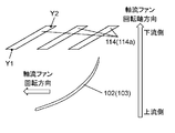
- FIG. 6 is a perspective view showing the shape of a front guard 12 provided on the downstream side of the axial flow fan 11.
- the front guard 12 is a guard ring for positioning and fixing the rear guard 14 and the front guard 12 on the outer periphery of the ventilation portion 13 through which the wind blown from the axial flow fan 11 passes.
- the ventilation portion 13 is provided with a straightening vane 17 extending from the center side of the front guard 12 toward the guard ring 15 in a spiral shape such that the rotation axis of the axial flow fan 11 is axially symmetrical.
- a part of the straightening vane 17 has a shape in which the center side thereof protrudes upstream in the rotational axis direction of the axial flow fan 11.
- Utility model registration 3196884 gazette Utility model registration No. 3209452 JP, 2011-58382, A JP, 2015-108362, A
- the front guard of such a conventional fan has enhanced the straightness of the wind by collecting the wind blown from the axial fan along the straightening vane at the center.
- the front guard can not sufficiently obtain the straightness of the wind.
- an air flow in the blowing direction is generated in the vicinity of the blades on the outer peripheral side of the axial fan.
- An air flow in the suction direction is generated between the outer peripheral blades of the axial flow fan.
- the straightening vane is not shaped in consideration of the air flow in the suction direction. Rather, the straightening plate resists the air flow in the suction direction on the outer peripheral side of the axial flow fan, and thus causes disturbance of the air flow on the outer peripheral side of the axial flow fan.
- the present disclosure aims to provide a fan that suppresses the resistance to the air flow in the suction direction and improves the straightness of the wind.
- the fan according to an embodiment of the present disclosure includes an axial fan having a plurality of blades for blowing air by rotation, and an axial fan in the axial direction of the axial fan rather than the axial fan.
- a front guard provided on the downstream side.
- the front guard is a disk provided with an inner ring, an outer ring provided on the outer side of the inner ring, an outer ring concentric with the inner ring and an inner ring, and a disk provided in the center of the inner ring and an inner ring.
- Each of the plurality of inner straightening vanes is formed in an arc shape projecting in the rotational direction of the axial fan.
- Each of the plurality of inner baffles includes an inner baffle slope having a first end upstream of the axial fan in the rotational axis direction. The inner straightening vane slope is inclined from the first end toward the rotational direction of the axial fan.
- Each of the plurality of outer baffles includes an outer baffle slope having a second end upstream of the axial fan in the rotational axis direction. The outer straight baffle slope is inclined from the second end in a direction opposite to the rotational direction of the axial fan.
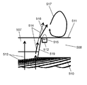
- FIG. 1 is a perspective view of a fan according to a first embodiment of the present disclosure.
- FIG. 2 is a side view of the fan of FIG.
- FIG. 3A is an enlarged view of a portion A in FIG.
- FIG. 3B is a cross-sectional view showing the shape of the cross section B-B 'in FIG. 3A.
- FIG. 4A is a cross-sectional view showing the shape of the cross section C-C 'in FIG. 3A.
- FIG. 4B is a cross-sectional view showing the shape of D-D ′ cross section in FIG. 3A.
- FIG. 5 is a perspective view showing the configuration of a conventional fan.
- FIG. 6 is a perspective view showing the shape of a front guard of a conventional fan.
- FIG. 1 is a perspective view of a fan according to a first embodiment of the present disclosure.
- FIG. 2 is a side view of the fan of FIG.
- FIG. 3A is an enlarged view of a portion A in
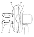
- FIG. 7 is a perspective view of a fan according to a second embodiment of the present disclosure.
- FIG. 8 is a side view of the fan according to the second embodiment.
- FIG. 9 is an enlarged view of a portion A in FIG.
- FIG. 10 is a cross-sectional view of the fan according to the second embodiment in the EE 'cross section in FIG.
- FIG. 11 is a perspective view showing the configuration of a conventional fan.
- FIG. 12 is a perspective view showing the shape of a front guard of a conventional fan.
- FIG. 13 is a perspective view of a fan according to a third embodiment of the present disclosure.
- FIG. 14 is a side view of the fan according to the third embodiment.
- FIG. 15 is a perspective view of the guard mark as viewed from the upstream side.
- FIG. 16A is a cross-sectional view in the case where the guard mark has no conical protrusion and no current plate.
- FIG. 16B is a perspective view seen from the downstream side in the case where the guard mark has a conical protrusion and a straightening vane.
- FIG. 16C is a cross-sectional view in the case where the guard mark has a conical protrusion and a straightening vane.
- FIG. 17 is a perspective view showing the shape of a guard mark of a conventional fan.
- FIG. 18 is a perspective view of a conventional fan having a guard mark attached to its central portion.
- FIG. 19 is a perspective view of a fan according to a fourth embodiment of the present disclosure.
- FIG. 20 is a side view of the fan according to the fourth embodiment.
- FIG. 21 is a front view in which a part of the front guard is seen through from the upstream side.
- FIG. 22A is an enlarged view of the vicinity of the guard mark when viewed from the front on the downstream side.
- FIG. 22B is a view of the cross section of the front guard and the positional relationship of the axial fan as viewed from the side.
- FIG. 23 is a perspective view of a conventional straight guarded front guard.
- FIG. 24 is a side view of a conventional straight guarded front guard.
- FIG. 25 is a perspective view of a fan according to a fifth embodiment of the present disclosure.
- FIG. 26 is a side view of the fan according to the fifth embodiment.
- FIG. 27 is a perspective view of the guard mark as viewed from the upstream side.
- FIG. 28 is a cross-sectional view of a guard mark.
- FIG. 29 is a perspective view showing the shape of a guard mark of a conventional fan.
- FIG. 30 is a side view of a conventional fan with a guard mark attached to its central portion.
- FIG. 31 is a cross-sectional view of a conventional guard mark.
- the fan according to the first embodiment of the present disclosure includes an axial fan having a plurality of blades for blowing air by rotation, and a front provided downstream of the axial fan in the axial direction of the axial fan. And a guard.
- the front guard is a disk provided with an inner ring, an outer ring provided on the outer side of the inner ring, an outer ring concentric with the inner ring and an inner ring, and a disk provided in the center of the inner ring and an inner ring.
- Each of the plurality of inner straightening vanes is formed in an arc shape projecting in the rotational direction of the axial fan.
- Each of the plurality of inner baffles includes an inner baffle slope having a first end upstream of the axial fan in the rotational axis direction. The inner straightening vane slope is inclined from the first end toward the rotational direction of the axial fan.
- Each of the plurality of outer baffles includes an outer baffle slope having a second end upstream of the axial fan in the rotational axis direction. The outer straight baffle slope is inclined from the second end in a direction opposite to the rotational direction of the axial fan.
- each inner side straightening vane inclines along blowoff air current. Therefore, the resistance which blowing air flow receives from a front guard can be reduced.
- each inner straightening vane is formed in an arc shape projecting in the rotational direction of the axial fan. Thus, the blowing air flow is collected to the center.
- each outer straightening vane is inclined along the suction air flow along the rotational direction of the axial fan generated on the outer peripheral side of the blade. Therefore, the resistance of the suction air flow from the front guard can be reduced. Thereby, the turbulence of the air flow on the outer peripheral side of the axial fan can be reduced.
- the fan according to the first embodiment of the present disclosure can blow air far by suppressing the diffusion of the blown air collected to the center of the axial fan and improving the straightness of the wind.
- each of the plurality of inner straightening vanes is provided downstream of the inner straightening vane inclined portion on the downstream side in the axial direction of the axial fan and the rotary shaft of the axial fan
- the inner straightening plate straight section further includes a third straight end on the downstream side in the axial direction of the axial flow fan, and the inner straight straightening section at the third end. It may be connected with
- the fan according to the first embodiment of the present disclosure can improve the straightness of the wind and can blow the air far.
- the wind blown by the rotation of the axial fan has a swirl component.
- the inner straightening plate linear portion converts a swirl component of the wind into a rotational axis component. Thereby, the straightness of the wind can be further improved.
- each of the plurality of inner straightening vanes is more inward than the outer circumferential side region including the inner straightening vane inclined portion and the inner straightening vane straight portion and the outer circumferential side region. It may be located on the circumferential side, and may have a region on the inner circumferential side including the inner straightening vane straight portion without including the inner straightening vane inclined portion.
- the fan according to Embodiment 1 of the present disclosure has a ventilation area in the vicinity of the center (region on the inner circumferential side) from the guard mark when the front guard is viewed from the front to a predetermined position of the inner straightening vane. It can be increased. Therefore, the pressure loss near the center (region on the inner circumferential side) near the guard mark can be reduced, and the wind speed near the center can be improved and the air can be blown far.
- the position at which the inner straightening vane inclination angle formed by the inner straightening vane inclined portion and the inner straight straightening vane portion is the smallest is the outer circumference than the middle point of the radius of the inner ring. It may be in the side position.
- the fan according to the first embodiment of the present disclosure can improve the wind speed and can make the wind reach far.
- the swirl component of the wind has a velocity distribution in the radial direction of the front guard.
- the speed of the swirling component of the wind is high.
- the front guard can flow such a high speed wind of a swirling component along the inner baffle. Thereby, the pressure loss can be reduced and the wind speed can be improved.
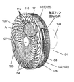
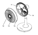
- FIG. 1 is a perspective view of a fan according to a first embodiment of the present disclosure
- FIG. 2 is a side view of the fan of FIG.
- the fan 101 which concerns on Embodiment 1 is demonstrated using FIG.1 and FIG.2.
- the fan 101 includes an axial fan 103 having a plurality of blades 102, a motor (not shown) for rotating the axial fan 103, and an upstream side of the axial fan 103 in the rotational axis direction. It is comprised with the motor housing 104 which includes a motor.
- the fan 101 further includes a rear guard 105 and a front guard 106.
- the rear guard 105 covers the axial fan 103 from the side face side and the back side which is the upstream side in the axial direction of the axial fan 103 so as to protect foreign matter from contacting the axial fan 103.
- the front guard 106 covers the axial flow fan 103 from the front side, which is the downstream side of the axial flow fan 103 in the rotation axis direction, and protects the axial flow fan 103 from contact with foreign matter.
- the front guard 106 is provided with a disk-like guard mark 107 at the center.
- the front guard 106 includes an inner circumferential ventilation portion 108 positioned on the outer circumferential side than the guard mark 107 and an outer circumferential ventilation portion 109 positioned on the outer circumferential side than the inner circumferential ventilation portion 108.
- the inner side ventilation part 108 mainly allows the wind blown by the axial fan 103 to pass.
- the outer circumferential ventilation portion 109 mainly passes the wind induced along the rotational direction of the axial fan 103 from the outer circumferential side of the blades 102 of the axial fan 103 by the rotation of the axial fan 103.
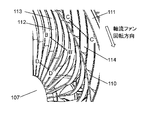
- the front guard 106 includes an inner ring 110 spaced apart from the guard mark 107 and a plurality of inner straightening vanes 112 provided between the guard mark 107 and the inner ring 110.
- the inner circumferential ventilation portion 108 and the outer circumferential ventilation portion 109 are separated by an inner ring 110 formed in an annular shape.
- the front guard 106 is provided on the outer side of the inner ring 110 so as to be spaced apart from the inner ring 110, and a plurality of outer straightening vanes provided between the inner ring 110 and the outer ring 111.
- the outer ring 111 is formed in an annular shape and provided concentrically with the inner ring 110.
- the front guard 106 is fixed to the rear guard 105 by an outer ring 111.
- each of the plurality of inner flow straightening plates 112 is arranged to connect the side surface of the guard mark 107 and the side surface on the inner peripheral side of the inner ring 110.
- the plurality of inner flow straightening plates 112 are formed to radiate from the side surface of the guard mark 107 toward the inner peripheral side surface of the inner ring 110.
- the inner circumferential ventilation portion 108 is a region defined by the side surfaces of the adjacent inner straightening vanes 112 and the guard marks 107 and the inner peripheral side surface of the inner ring 110.
- the inner straightening vane 112 has an arc shape projecting in the rotational direction of the axial fan 103 (vanes 102). Is formed. Specifically, the inner straightening vane 112 includes a first connecting portion connected to the side surface of the guard mark 107, a second connecting portion connected to the side surface on the inner peripheral side of the inner ring 110, and a first connecting portion. And a central portion located between the second coupling portions. A central portion of the inner straightening vane 112 is formed to project in the rotational direction of the axial flow fan 103 with respect to a straight line connecting the first connecting portion and the second connecting portion.
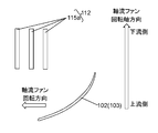
- the inner straightening vane 112 includes an inner straightening vane slope 113, as shown in FIG. 3B.
- the inner straightening vane inclined portion 113 is inclined toward the rotational direction of the axial flow fan 103 from the first end X 1 on the upstream side in the rotational axial direction of the axial flow fan 103 in the inner straightening plate 112.
- the inner straightening vane inclined portion 113 enables the wind blown by the axial fan 103 to pass through the inner circumferential ventilation portion 108 with low resistance.
- each of the plurality of outer straightening vanes 114 is disposed to connect the side surface on the outer peripheral side of the inner ring 110 and the side surface on the inner peripheral side of the outer ring 111.
- the plurality of outer straightening vanes 114 are formed to radiate from the outer peripheral side surface of the inner ring 110 toward the inner peripheral side surface of the outer ring 111.
- the outer periphery side ventilation part 109 is the area
- the outer straightening vane inclined portion 114a is inclined from the second end Y1 on the upstream side of the outer straightening vane 114 in the axial direction of the axial flow fan 103 to the direction opposite to the rotational direction of the axial fan 103. ing.
- suction air flow is generated along the rotation direction of the axial flow fan 103 (blade 102).
- the outer baffle plate inclined portion 114 a allows the suctioned air flow to pass through the outer circumferential ventilation portion 109 with low resistance.
- each inner straightening vane 112 is inclined along the blowout air flow. This reduces the resistance that the blowing air receives from the front guard 106.
- Each of the inner flow straightening plates 112 is further formed in an arc shape projecting in the rotation direction of the axial flow fan 103. As a result, the blown air is collected to the center of the axial fan 103.
- each outer straightening vane 114 is inclined along the suction air flow. Therefore, the resistance of the suction air flow from the front guard 106 can be reduced, and the disturbance of the air flow on the outer peripheral side of the axial flow fan 103 can be reduced. As a result of these, the fan 101 can suppress the diffusion of the blown air collected to the center of the axial fan 103 and improve the straightness of the wind, whereby the fan can be blown far.
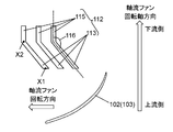
- FIG. 3A is an enlarged view of a portion A in FIG. 1, and FIG. 3B is a cross-sectional view showing the shape in the B-B 'cross section in FIG. 3A.
- 4A is a cross-sectional view showing the shape in the C-C 'cross section in FIG. 3A
- FIG. 4B is a cross-sectional view showing the shape in the D-D' cross section in FIG. 3A.
- Each cross-sectional view is a cross-sectional view of the inner straight plate 112 or the outer straight plate 114 cut along a cylindrical surface centered on the rotation axis of the axial flow fan 103 (from the outer circumferential side of the axial flow fan 103 to the inner circumferential side Cross section) in a planar form.
- Each cross-sectional view also includes a cross section obtained by similarly cutting the axial flow fan 103 (blade 102).
- each of the plurality of inner flow straightening plates 112 is disposed to connect the side surface of the guard mark 107 and the side surface on the inner peripheral side of the inner ring 110.
- the plurality of inner flow straightening plates 112 are formed to radiate from the side surface of the guard mark 107 toward the inner peripheral side surface of the inner ring 110.
- the inner straightening vane 112 is formed in an arc shape projecting in the rotation direction of the axial flow fan 103.
- each of the plurality of outer flow straightening plates 114 is arranged to connect the outer peripheral side surface of the inner ring 110 and the inner peripheral side surface of the outer ring 111.
- the plurality of outer straightening vanes 114 are formed to radiate from the outer peripheral side surface of the inner ring 110 toward the inner peripheral side surface of the outer ring 111.
- the inner straightening vane 112 has an inner straightening vane ramp 113.
- the inner straightening vane inclined portion 113 has a first end X1 on the upstream side in the rotational axis direction of the axial flow fan 103 and a third end X2 on the downstream side in the rotational axis direction of the axial flow fan 103.
- the inner straightening vane inclined portion 113 inclines in the rotation direction of the axial fan 103 from the first end X1. That is, the third end X2 is located in the rotation direction of the axial fan 103 as viewed from the first end X1.
- the inner straightening vane 112 further has an inner straightening vane straight portion 115.
- the inner straightening vane linear portion 115 is provided downstream of the inner straightening vane inclined portion 113 in the axial direction of the axial flow fan 103 and extends in the axial direction of the axial flow fan 103.
- the inner straightening vane inclined portion 113 is connected to the inner straightening vane straight portion 115 at the third end X 2 on the downstream side in the rotation axis direction of the axial flow fan 103.
- the outer side baffle plate 114 has the outer side baffle plate inclined part 114a.
- the outer baffle plate inclined portion 114 a has a second end Y 1 on the upstream side in the rotational axis direction of the axial flow fan 103 and a fourth end Y 2 on the downstream side in the rotational axis direction of the axial flow fan 103.
- the outer baffle plate inclined portion 114 a inclines in a direction opposite to the rotational direction of the axial fan 103 from the second end Y 1. That is, the fourth end Y2 is located in the direction opposite to the rotational direction of the axial fan 103 as viewed from the second end Y1.
- the outer straightening vane inclined portion 114 a has the same shape as the outer straightening vane 114. That is, the end on the upstream side in the rotational axis direction of the axial flow fan 103 in the outer straightening vane 114 coincides with the second end Y1. The end on the downstream side in the rotational axis direction of the axial flow fan 103 in the outer straightening vane 114 coincides with the fourth end Y2.
- the inner side straightening plate 112 has the inner side straightening plate linear part 115a along the rotation shaft direction of the axial flow fan 103 in the center vicinity (area
- the inner straightening vane inclined portion 113 is not provided in the vicinity of the center of the axial flow fan 103 (the region on the inner circumferential side).
- the wind generated by the rotation of the axial fan 103 has a wind speed distribution in the radial direction of the axial fan 103. That is, the wind speed differs depending on the radial position of the axial fan 103. For example, when the axial fan 103 has a radius of 250 mm, the maximum of the wind speed in the radial wind velocity distribution immediately downstream of the axial fan 103 is at a radius of 170 mm. Near the position showing the maximum wind speed, the speed of the swirling component of the wind is increased. Then, as shown to FIG. 3B, the inner side baffle plate inclination part 113 is provided in the position where the speed of the rotational component of a wind is large. As a result, the wind having the maximum wind velocity flows along the inner straightening vane inclined portion 113 on the outer circumferential side of the inner straightening vane 112, and wind disturbance can be reduced.
- the wind from the axial fan 103 has a wind speed distribution in the radial direction immediately downstream of the axial fan 103.
- the circumferential speed of the axial fan 103 is slower as it approaches the center of the axial fan 103. Therefore, the closer to the center of the axial fan 103, the lower the speed of the swirling component of the wind. Therefore, the inner straightening vane 112 does not include the inner straightening vane inclined portion 113 near the center of the axial flow fan 103, and includes only the inner straightening vane straight portion 115a as shown in FIG. 4B.
- the inner straightening vane 112 when the radius of the inner ring 110 is, for example, 210 mm, the inner straightening vane 112 is located at a radius of 88 mm from the center of the inner ring 110 (about 0.42 of the radius of the inner ring 110 from the center of the inner ring 110). Up to the double position), only the inner straightening plate straight portion 115a is formed.
- the inner straightening vane 112 includes an inner straightening vane straight portion 115 and an inner straightening vane inclined portion 113 from the 88 mm radius position to the inner ring 110 on the outer peripheral side where the wind speed is high.
- the inner straightening vane 112 has a region on the inner circumferential side constituted by the inner straightening vane straight portion 115 a and a region on the outer circumferential side constituted by the inner straightening vane inclined portion 113 and the inner straightening vane straight portion 115 doing.
- the inner straightening vane 112 is inclined along the blowout air flow, and the resistance of the blowout air flow from the front guard 106 can be reduced.
- the inner straightening vane 112 is formed in an arc shape that protrudes in the rotation direction of the axial flow fan 103. As a result, the blown air can be concentrated to the center of the axial fan 103, and the wind speed can be increased to blow the air far.
- the outer straightening vane 114 is inclined along the suction air flow.
- the resistance when the suctioned air flow passes through the outer peripheral ventilation portion 109 can be reduced, and the disturbance of the air flow on the outer peripheral side of the axial flow fan 103 can be reduced.
- the wind can be made to reach far.
- the wind is generated by the rotation of the axial fan 103 and therefore has a swirl component.
- the swirling component of the wind is diffused as it flows downstream, which causes the straightness of the wind to deteriorate.
- the inner side straightening plate 112 has the inner side straightening plate linear part 115 formed in the surface which becomes parallel to the rotating shaft of the axial flow fan 103 in the downstream rather than the inner side straightening plate inclination part 113.
- the inner straightening plate linear portion 115 can convert a swirling component of the wind into a component in the axial direction of the axial flow fan 103. Therefore, by suppressing the diffusion of the blown air collected to the center of the axial fan 103 and improving the straightness of the wind, the wind can be made to reach far.
- the wind generated by the axial fan 103 has a wind speed distribution in the radial direction immediately downstream of the axial fan 103. That is, there is a position where the wind shows the maximum wind speed.
- the position at which the maximum wind speed is indicated is 170 mm from the center of the axial fan 103.
- the velocity of the turning component becomes large. Therefore, the wind is directed along the inner straightening vane slope 113 by reducing the angle formed by the inner straightening vane slope 113 and the inner straightening vane straight line portion 115, that is, the inner straightening vane slope angle 116 (see FIG. 3B).
- the inner baffle inclination angle 116 may have an angular distribution in the radial direction of the front guard 106.
- the position at which the inner straightening vane inclination angle 116 is minimized may be located on the outer circumferential side of the middle point of the radius of the inner ring 110.
- the inner straightening vane slope portion 113 is formed such that the inner straightening vane inclination angle 116 is a minimum at a position of 140 mm to 189 mm from the center of the inner ring 110. That is, the position where the swirling component of the wind is the maximum corresponds to the position where the inner straightening vane inclination angle 116 is the minimum angle.
- the wind is along the inner straightening vane inclined portion 113, and the resistance due to the wind disturbance of the turning component can be reduced.
- the wind from the portion having a high peripheral speed on the outer peripheral side of the axial fan 103 flows along the inner straightening plate 112, so that the pressure loss can be reduced and the wind speed can be improved. be able to.
- Patent Document 1 Utility Model Registration No. 3196884
- Patent Document 1 Utility Model Registration No. 3196884
- FIG. 11 is a perspective view showing the configuration of a conventional fan
- FIG. 12 is a perspective view showing the shape of the front guard 22 provided on the downstream side of the axial flow fan 21.
- the front guard 22 is a guard ring for positioning and fixing the rear guard 24 and the front guard 22 on the outer periphery of the ventilation portion 23 through which the wind blown from the axial flow fan 21 passes. It has 25.
- the ventilation portion 23 is provided in a spiral shape in which a straightening plate 27 extending from the center side of the front guard 22 toward the guard ring 25 is axially symmetrical with respect to the rotation axis of the axial flow fan 21.
- a part of the straightening vane 27 has a shape in which the center side thereof protrudes to the upstream side of the axial flow fan 21 in the rotation axis direction.
- the front guard 22 of such a conventional fan improves the straightness of the wind by collecting the wind blown by the axial fan 21 along the straightening plate 27 of uniform thickness at the center. Furthermore, the front guard 22 closely arranges a plurality of flow straightening plates 27 and adjusts the distance between the flow straightening plates 27 to thereby suppress finger insertion between the flow straightening plates 27 of the front guard 22. That is, in order to suppress the insertion of the front guard 22, it is necessary to increase the number of the flow control plates 27 and to arrange the flow control plates 27 densely. However, the dense arrangement of the straightening vanes 27 is a factor of the resistance of the air flow, and there is a problem that the air flow performance is lowered. Therefore, the present embodiment aims to provide a fan that suppresses the insertion of a finger between the flow control plates 27 of the front guard and does not reduce the air blowing performance.
- An electric fan includes an axial fan having a plurality of blades for blowing air by rotation, and a front provided downstream of the axial fan in the axial direction of the axial fan.
- the guard includes a guard and a rear guard provided on the upstream side in the axial direction of the axial fan with respect to the front guard.
- the front guard includes a disk-shaped guard mark provided at the center of the front guard and the outer periphery of the front guard. And a plurality of arc-shaped straightening vanes provided between the guard mark and the outer circumferential ring, the arc-shaped straightening vanes being formed so that an arc is closed in a direction opposite to the rotational direction of the axial fan.
- each of the plurality of straightening vanes is a straightening vane inclined portion which is inclined along the swirling direction of the air flow blown by the axial fan, and a downstream side in the axial direction of the axial fan from the straightening vane inclined portion.
- the straight-line portion parallel to the rotational axis direction of the axial fan, and the straight-line slope has a face facing the blade, and this face protrudes toward the other adjacent straight-line slope With a protruding portion.
- the projecting portion By providing the projecting portion on the surface of the straightening vane inclined portion, the shortest distance between the straightening vane inclined portions of the adjacent straightening vanes becomes short. Therefore, even if it is intended to insert a finger toward the axial fan through the front guard, the projection of the surface of the straightening plate inclined portion of the adjacent straightening vane restricts the finger from passing through the front guard. can do.
- the projecting portion is provided in the straightening vane inclined portion, the resistance to the air flow from the axial flow fan is reduced and the air blowing performance is reduced compared to the case where the projecting portion is provided in the straightening vane straight portion. It can be suppressed.
- the straightening vane inclined portion is positioned on the upstream side end portion located on the upstream side in the axial direction of the axial fan and on the downstream side in the axial direction of the axial fan.
- the projecting portion may be continuous from the upstream end to the downstream end of the straightening vane slope.
- the protrusion can be formed as a smooth surface from the upstream end to the downstream end of the straightening vane inclined portion, and the protrusion can be prevented from becoming a resistance of the air flow by the axial fan. it can. As a result, even when the projecting portion is provided on the straightening vane inclined portion, it is possible to suppress the decrease in the air blowing performance.
- the position where the projecting portion has the maximum thickness is closer to the downstream end than the midpoint between the upstream end and the downstream end of the straightened plate inclined portion. It may be located in
- the second embodiment of the present disclosure will be described below for understanding of the present disclosure.
- the following second embodiment is an example embodying the present disclosure, and does not limit the technical scope of the present disclosure.
- the same number is attached about the same site
- the description of the details of each part not directly related to the present disclosure is omitted.
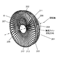
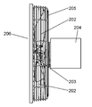
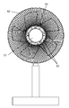
- FIG. 7 is a perspective view of the fan 201 according to the second embodiment of the present disclosure
- FIG. 8 is a side view of the fan 201 according to the second embodiment of the present disclosure
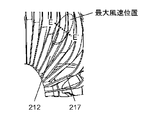
- FIG. FIG. 10 is an enlarged view of the vicinity of the center of the fan 201 according to the second embodiment
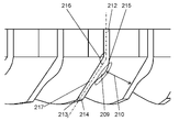
- FIG. 10 is a cross-sectional view of the fan 201 according to the second embodiment of the present disclosure.
- the fan 201 includes an axial fan 203 having a plurality of blades 202, a motor (not shown) for rotating the axial fan 203, and a motor provided on the upstream side of the axial fan 203. And a motor housing 204.
- the fan 201 includes a rear guard 205 and a front guard 206.
- the rear guard 205 covers the axial fan 203 from the side surface side and the rear side which is the upstream side of the axial fan 203 so as to protect foreign matter from contacting the axial fan 203.
- the rear guard 205 is formed of a metal or resin wire.
- the front guard 206 covers the axial flow fan 203 from the front side of the axial flow fan 203 downstream of the axial flow fan 203 and protects the axial flow fan 203 from contact with foreign matter.
- the front guard 206 is provided on the downstream side of the axial fan 203 in the rotation axis direction than the axial fan 203.
- the rear guard 205 is provided upstream of the front guard 206 in the axial direction of the axial flow fan 203.
- the front guard 206 includes a cylindrical or disc-like guard mark 207 provided at the center of the front guard 206 and an outer peripheral ring 211 provided at the outer periphery of the front guard 206.
- the front guard 206 further includes a plurality of flow straightening plates 217 provided between the guard marks 207 and the outer peripheral ring 211.
- Each of the plurality of flow straightening plates 217 is disposed to connect the side surface of the guard mark 207 and the side surface on the inner peripheral side of the outer peripheral ring 211.
- the plurality of rectifying plates 217 are formed to radiate from the side surface of the guard mark 207 toward the side surface on the inner peripheral side of the outer peripheral ring 211.
- each flow straightening plate 217 is made of an elongated thin plate having two main surfaces. The two main surfaces are substantially parallel to the rotational axis direction of the axial flow fan 203.
- a ventilating portion 208 through which the wind blown by the axial fan 203 passes is formed on the outer circumferential side of the guard mark 207.
- the ventilation part 208 is an area divided by the guard mark 207 and the outer peripheral ring 211 and the straightening vane 217 adjacent thereto. Further, the front guard 206 is fixed to the rear guard 205 by an outer peripheral ring 211.
- each rectifying plate 217 of the present embodiment has a rectifying plate linear portion 212.
- the straightening vane straight portion 212 has a plane parallel to the rotation axis of the axial fan 203.
- the straight component 212 of the straightening vanes can convert the swirl component of the air flow into a rotational axis component along the rotational axis direction of the axial flow fan 203.
- each flow straightening plate 217 has a shape curved in an arc shape.
- the arc-shaped straightening vane 217 is formed so that the arc is closed in the direction opposite to the rotational direction of the axial fan 203.
- the straightening vane 217 is formed in an arc shape projecting in the rotation direction of the axial flow fan 203.
- FIG. 10 shows a cross-sectional view of the straightening vane 217 in FIG. 9 taken along the line EE '.
- each flow straightening plate 217 is provided with a straightening vane slope portion 213 in addition to the straightening vane straight portion 212 so that the wind blown by the axial flow fan 203 passes with low resistance.
- the straightening vane inclined portion 213 is located upstream of the straightening vane linear portion 212 in the rotation axis direction of the axial fan 203, and is connected to the straight straightening vane portion 212.
- the straightening vane inclined portion 213 is inclined along the swirling direction of the air flow blown by the axial fan 203. That is, the straightening vane inclined portion 213 is inclined along the blown air flow. Thereby, the contact resistance between the blowout air flow and the straightening vane inclined portion 213 can be reduced, and the pressure loss is reduced.
- the straightening vane straight portion 212 is formed such that the arc is closed in the direction opposite to the rotational direction of the axial fan 203.
- the blowing air flow is collected to the center of the front guard 206.
- the concentration of the blown air promotes an increase in the air flow of the air flow and an increase in the wind speed of the air flow. By the increase of the air volume and the wind speed, the straightness of the wind can be improved and the air can be blown far.
- the wind from the axial fan 203 has a distribution of wind speed in the radial direction of the axial fan 203.
- the straightening vane 217 has a position (maximum wind speed position) at which the wind from the axial fan 203 reaches the maximum wind speed.
- the swirl component of the wind is also large.
- the curvature of the arc of the straightening vane 217 is large. Thereby, an air flow having a large swirling component can be collected at the center of the axial flow fan 203.
- each straightening vane 217 may have an arc curvature distribution in the radial direction of the front guard 206.
- the portion where the curvature of the arc is maximum may be located closer to the outer peripheral ring 211 than the above-mentioned midpoint.
- the curvature of the arc of the rectifying plate 217 may be small.
- an angle formed between the straightening vane inclined portion 213 and the straight straightening vane portion 212, that is, the straightening vane inclination angle 216 may be small.
- the air flow having a high speed of the swirling component can be converted into an air flow parallel to the rotation axis direction of the axial flow fan 203. Therefore, the straightness of the wind can be improved even in the air flow in which the speed of the turning component is large.
- the straightening vane inclination angle 216 at the position where the turning component is maximum, the wind can be along the straightening vane inclined portion 213, and the resistance due to the disturbance of the turning component wind can be reduced.
- the flow of the wind at the portion where the peripheral velocity on the outer peripheral side of the axial flow fan 203 is large is along the straightening plate linear portion 212.
- the pressure loss can be reduced, the wind speed can be improved, and the wind can be made to reach far.
- the straightening vane inclined portion 213 has a surface facing the rotating blade 202.
- This face of the baffle ramp 213 has a projection 209 projecting towards the other adjacent baffle ramp 213.
- the inter-rectifying plate distance 210 in the rectifying plate inclined portion 213 can be shortened, so that the foreign matter such as a finger can be prevented from passing through the front guard 206.
- the projecting portion 209 is provided on the rectifying plate inclined portion 213.
- the pressure loss is smaller in the case where the projecting portion 209 is provided in the straightening vane inclined portion 213 than in the case where the projecting portion 209 is provided in the straightening vane linear portion 212, and the reduction in air blowing performance can be suppressed.
- the projecting portion 209 may be formed to be continuous from the upstream end 214 to the downstream end 215 of the straightening vane inclined portion 213.
- the contact resistance between the air flow entering between the adjacent flow straightener inclined portions 213 and the projecting portion 209 can be reduced, and the turbulent flow of the air flow can be reduced to suppress the air flow performance deterioration due to the pressure loss. it can.
- the position where the protrusion 209 has the largest thickness may be located closer to the downstream end 215 than the middle point between the upstream end 214 and the downstream end 215 of the straightening vane slope 213. .
- the turbulence of the air flow immediately after flowing into the space between the adjacent straight plate inclined portions 213 can be reduced, compared with the case where the position of the maximum thickness is closer to the upstream end 214 than the middle point. It is possible to suppress the decrease in air blowing performance due to the loss.
- the projecting portion 209 may be provided at the downstream end portion 215 of the straightening vane inclined portion 213.
- the protrusion part 209 can ease the trajectory change of the air flow passing through the straightening vane inclination angle 216, and the separation of the flow at the downstream end 215 of the straightening vane inclined part 213 can be suppressed. Can be suppressed.
- the conventional fan has a configuration described in Patent Document 2 (Utility Model Registration No. 3209452), for example, as a shape for improving the air flow performance of a guard mark at the center of the front guard.
- FIG. 17 is a perspective view showing the configuration of the guard mark 31 used in the conventional fan
- FIG. 18 is a perspective view of the fan having the guard mark 31 attached to the center of the front guard 32.
- the guard mark 31 includes a conical cylindrical portion 33 and a rib 34.
- the conical cylindrical portion 33 has a conical cylindrical top that protrudes on the axial flow fan side.
- the top has a flat and closed conical shape.
- the tip end opposite to the top of the conical cylindrical portion 33 is open.
- the rib 34 is provided on the outer periphery of the conical cylindrical portion 33 so as to protrude in the axial flow fan direction from the tip end side.
- the conical cylindrical portion 33 has a circular tip end 35 and a circular top end 36 having a diameter smaller than that of the tip 35.
- the guard mark 31 is at the center of the front guard 32, as shown in FIG. Air from the fan passes from the top end 36 of the conical cylindrical portion 33 toward the tip end 35, and the air passing therethrough is formed to have diffusibility.
- the wind blown from the axial flow fan is directed from the top end 36 of the conical cylinder 33 of the guard mark 31 toward the tip end 35 larger in diameter than the top to the conical cylinder 33. Flow along.
- an air flow in the radial direction is formed from the vicinity of the guard marks 31 and the wind is diffused in the radial direction to improve the air blowing performance.
- the air flow in the rotational axis direction blown from the blades near the hub is hindered by being diffused by the air flowing radially along the conical cylinder portion 33.
- an object of the third embodiment of the present disclosure is to provide a fan that improves the straightness of the wind by increasing the flow in the rotation axis direction near the center of the axial flow fan.
- the fan according to the third embodiment of the present disclosure includes a hub and a plurality of blades provided on the hub, and an axial fan for blowing air by rotation by a motor, and a rotational shaft of the axial fan rather than the axial fan.
- Rear guard provided on the upstream side of the direction and a front guard provided on the downstream side in the axial direction of the axial fan from the rear guard, the front guard facing the axial fan at the center of the front guard It has a disk-like guard mark having a back surface, and the guard mark is provided on the back surface and has a conical protrusion having a top projecting toward the axial fan, and the back surface of the guard mark is provided with a ridge from the outer edge of the back surface.
- each of the plurality of straightening vanes being formed in an arc shape formed such that an arc is closed in a direction opposite to the rotational direction of the axial fan Having.
- the air flow led to the top of the projection is delivered towards the hub, ie in the direction opposite to the blowing direction of the axial fan.
- the air stream collides with the hub and is sent out from the center of the hub to the outer periphery.
- a circulation flow is formed by the flow of this air flow. This circulating flow attracts the air flow flowing from the upstream to the downstream in the vicinity of the guard marks and the hub, and accelerates the flow velocity of the wind blown from the fan. Therefore, the wind speed performance by a fan can be improved.
- the outer diameter of the guard mark may be larger than the diameter of the downstream portion of the axial flow fan in the rotational direction of the axial flow fan hub.
- the air flow pressurized by a portion of the blade located in the vicinity of the hub collides with the guard mark and is delivered from the outer edge of the back surface of the guard mark toward the top of the protrusion.
- an air flow is generated along the blowing direction of the axial fan. Since this air flow is in the same direction as the circulation flow, the wind speed of the circulation flow can be improved. Therefore, the circulation flow having the improved wind speed can attract the air flow flowing from the upstream to the downstream in the vicinity of the guard mark and the hub, and the flow velocity can be increased, so that the wind speed performance by the fan can be improved.
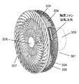
- FIG. 13 is a perspective view of the fan 301 according to the present disclosure
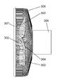
- FIG. 14 is a side view of the fan 301 according to the present disclosure
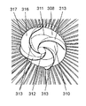
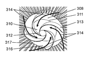
- FIG. 15 is a guard mark 308 of the front guard 307 of the fan 301 according to the present disclosure. It is the perspective view seen from the upstream side.
- the fan 301 includes an axial fan 304 having a plurality of blades 303 attached to a central hub 302, a motor (not shown) for rotating the axial fan 304, and an upstream side of the axial fan 304. And a motor housing 305 containing a motor provided therein.
- the fan 301 also includes a rear guard 306 and a front guard 307.
- the rear guard 306 covers the axial fan 304 on the side surface side and the rear side which is the upstream side of the axial fan 304 and protects foreign matter from contacting the axial fan 304.
- the rear guard 306 is formed of a metal or resin wire.
- the front guard 307 covers from the front side, which is the downstream side of the axial fan 304, and protects the axial fan 304 from contact with foreign matter.
- the front guard 307 is formed of a metal or resin wire.
- the front guard 307 includes a disk-like guard mark 308 provided at the center of the front guard 307 and an outer peripheral ring 309 provided at the outermost periphery of the front guard 307.
- the guard mark 308 is provided with a conical protrusion 310 protruding toward the axial fan 304 at a central portion of the back surface 316 thereof.
- the conical protrusion 310 has a base 311 and a top 312 smaller in diameter than the base 311.
- Guard mark 308 further includes a plurality of current plates 313 projecting toward axial fan 304 on its back surface 316. Each of the plurality of baffles 313 extends from the outer edge 317 of the back surface 316 of the guard mark 308 to the top 312 of the protrusion 310.
- Each of the plurality of straightening vanes 313 has an arc shape formed so that an arc is closed in a direction opposite to the rotational direction of the axial fan 304. Also, the plurality of current plates 313 are formed to radiate from the top portion 312 of the protrusion 310 to the outer edge 317 of the back surface 316. The back surface 316 of the guard mark 308 faces the axial fan 304.
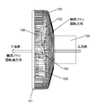
- FIG. 16A shows a cross-sectional view of a guard mark 308 that has neither a conical protrusion 310 nor a baffle plate 313.
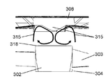
- FIG. 16B is a perspective view of a guard mark 308 having a conical protrusion 310 and a straightening vane 313 as seen from the downstream side of the rotational shaft of the axial flow fan.
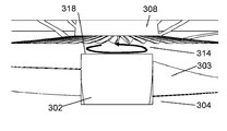
- FIG. 16C shows a cross-sectional view of a guard mark 308 having a conical protrusion 310 and a current plate 313. The flow of wind in the vicinity of the guard mark 308 will be described with reference to FIGS. 16A to 16C.
- the hub 302 has a circular plane (downstream surface 318) on the downstream side of the axial flow fan 304 in the rotation axis direction.
- the downstream surface 318 does not have the vanes 303. Therefore, in the vicinity of the downstream surface 318 of the hub 302, there is no air flow flowing in the rotational axis direction of the axial flow fan 304. Instead, an air flow is generated that pivots in the same direction as the axial fan 304 rotates.
- the rotation of the axial fan 304 causes the hub 302 of the axial fan 304 to rotate, and the downstream surface 318 of the hub 302 also to rotate.
- the downstream surface 318 of the hub 302 causes the nearby air to rotate in the same direction by viscosity and to pivot in the same direction as the axial flow fan 304 rotates.
- a swirling flow 314 is generated in the section between the hub 302 and the guard mark 308. The swirling flow 314 does not affect the wind blown from the fan 301.
- the swirling flow 314 has a component along the air flow direction of the axial flow fan 304 near the outer periphery of the section sandwiched by the guard marks 308 and the hub 302. This is because the swirling flow 314 is induced by the air flow from the blades 303 of the axial flow fan 304. Further, the swirling flow 314 collides with the back surface 316 of the guard mark 308 and is delivered from the outer edge 317 of the back surface 316 toward the top 312 of the protrusion 310 along the back surface 316 of the guard mark 308. At this time, the swirling flow 314 is guided along the straightening vane 313 of the guard mark 308 to hold the swirling component along the rotation direction of the axial flow fan 304.
- the swirling flow 314 is collected at the top 312 of the protrusion 310 of the guard mark 308 and is delivered in the direction opposite to the blowing direction of the axial flow fan 304 by the inclination of the protrusion 310.
- the air stream collides with the central portion of the downstream surface 318 of the hub 302 and is delivered along the downstream surface 318 from the central portion to the outer peripheral portion of the downstream surface 318.
- a straightening vane 313 is formed so that the arc is closed in the direction opposite to the rotational direction of the axial fan 304. Therefore, the swirling flow 314 flows toward the center of the guard mark 308, and then flows from the base 311 to the top 312 along the slope of the conical protrusion 310. That is, the swirling flow 314 is directed to the hub 302 of the axial flow fan 304 from the guard marks 308 opposite to the air flow direction of the axial flow fan 304.
- the swirling flow 314 between the guard mark 308 and the hub 302 becomes a circulating flow 315 which is a flow circulating in the rotational axis direction.
- the airflow flowing from the upstream to the downstream of the axially-flowing fan 304 pressurized from the portion near the hub 302 of the vanes 303 is attracted to the circulating flow 315 to increase the speed.
- the axial flow fan 304 has, for example, a radius of 250 mm, a radius of 50 mm of the guard mark 308, a radius of 50 mm of the hub 302, a distance of 50 mm between the guard mark 308 and the downstream surface 318 of the hub 302, a current plate 313, and a conical protrusion 310. And a circulating flow 315 in the direction of the rotation axis with a height of 20 mm.
- the radius of the downstream surface 318 of the hub 302 may be smaller than the radius of the guard mark 308.
- the radius of the downstream surface 318 of the hub 302 may be 40 mm with respect to the radius of 50 mm of the guard mark 308.
- Patent Document 3 Japanese Patent Application Laid-Open No. 2011-58382 discloses a conventional fan as a shape for giving a rectifying effect to a front guard to improve air blowing performance. The configuration will be described below with reference to FIGS. 23 and 24.
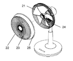
- FIG. 23 is a perspective view showing the configuration of a conventional fan 41
- FIG. 24 is a side view of the fan 41.
- the front guard 43 includes a disk-shaped guard mark 45 formed at the center thereof, and a plurality of flow straightening vanes 44 disposed radially from the guard mark 45.
- the front guard 43 covers the front of the axial fan 42. In such a fan 41, the wind blown from the axial fan 42 flows along the straightening vanes 44 so that the wind straightens toward the downstream side. The straightening effect of the straightening vanes 44 allows the wind passing through the front guard 43 to go straight.
- the wind blown from the axial fan 42 is straightened by the straightening vane 44 when passing through the front guard 43, thereby improving the straightness of the wind. I was trying.
- the straightness of the wind is not sufficient.
- the guard marks 45 are provided to face the hub 46 of the axial flow fan 42 and a portion near the central axis of the blades of the axial flow fan 42. Therefore, the air flow from the portion near the central axis of the blades of the axial fan 42 is interrupted by the guard marks 45.
- the wind blown from a portion near the central axis of the blades of the axial flow fan 42 does not flow to the downstream side of the guard mark 45 which is an area facing the guard mark 45.
- the area downstream of the guard mark 45 has a negative pressure. Therefore, the main flow of the air flow of the axial flow fan 42 generated from the outer peripheral side portion of the blade of the axial flow fan 42 flows toward the region on the downstream side of the guard mark 45. Due to this inflow, in the region downstream of the guard mark 45, a vortex 47 is generated which flows backward in the flow direction of the main flow of the axial fan 42.
- the damping action of the main flow velocity of the air flow of the axial fan 42 is reduced by suppressing the vortices 47 generated in the area downstream of the guard mark 45, and the straightness of the air flow Aims to provide a fan that improves the
- An electric fan includes a hub and a plurality of blades provided on the hub, and an axial fan that blows air by rotation by a motor, and a rotational shaft of the axial fan rather than the axial fan.
- Rear guard provided on the upstream side of the direction and a front guard provided on the downstream side in the axial direction of the axial fan from the rear guard, and the front guard is a disk-like guard provided at the center of the front guard
- a plurality of inner circumferences comprising a mark, an intermediate ring provided between the outer circumference of the guard mark and the outer circumference of the front guard, and a plurality of inner circumference ribs provided between the guard mark and the middle ring
- Each of the ribs has a first end connected to the outer periphery of the guard mark and a second end connected to the inner periphery of the intermediate ring, and each of the plurality of inner peripheral ribs is an axial fan
- Anti-rotational direction A formed arc-shape so an inner circumferential side of the arc direction is located, the outer diameter of the guard marks smaller than the outer diameter of the hub, the outer diameter of the intermediate ring is larger than the outer diameter of the hub.
- the outer diameter of the intermediate ring is larger than the outer diameter of the hub, the wind blown from the portion near the hub of the blade passes between the inner circumferential ribs. Since the inner circumferential side of the arc of each inner circumferential rib is located in the direction opposite to the rotational direction of the axial fan, the wind passing between the inner circumferential ribs flows along the shape of the inner circumferential rib, It is guided to the central axis side of the flow fan. Furthermore, since the outer diameter of the guard mark is smaller than the hub outer diameter, the wind guided to the central axis side by the inner circumferential rib is blown to the downstream region of the guard mark.
- the wind blown from the axial fan is guided to the downstream area of the guard mark, whereby the wind flows into the downstream area of the guard mark and the area where the negative pressure is applied is reduced. Therefore, the amount of air flowing into the area downstream of the guard mark in the main flow of the blowing air is reduced, thereby suppressing the generation of a vortex in the area downstream of the guard mark. By suppressing the generation of the vortices, the reduction of the wind speed near the central axis after passing through the front guard is suppressed.
- the fan according to the fourth embodiment of the present disclosure further includes a plurality of outer peripheral ribs connected between the outer peripheral edge of the intermediate ring and the outer peripheral edge of the front guard, and each of the plurality of outer peripheral ribs is an axis. It may be formed to be opposed to the largest wide portion where the chord length of the flow fan is the largest.
- the amount of air flow boosted at the widest part of the axial fan is the largest in the distribution of the amount of air flow boosted by the axial fan. Further, the velocity of the air flow boosted at the maximum wide portion of the axial fan becomes the maximum value in the velocity distribution of the air blown by the axial fan.
- the wind having a large rotational component blown from the portion near the hub of the blade passes between the inner circumferential ribs, and the air flow pressurized at the widest wide portion passes between the outer circumferential ribs. Therefore, the wind having a large rotational component blown from the portion near the hub of the blade of the axial flow fan is guided to the central axis side of the axial flow fan by the inner circumferential rib.
- the inner circumferential rib and the outer circumferential rib can be provided appropriately to control the wind direction.
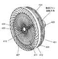
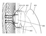
- FIG. 19 is a perspective view of a fan 401 according to Embodiment 4 of the present disclosure
- FIG. 20 is a side view of the fan 401 according to Embodiment 4 of the present disclosure
- FIG. It is the front view which made the front guard 407 and the axial flow fan 404 attached to the upstream of the fan 401 which concerns on form 4 permeate
- the fan 401 includes an axial fan 404 having a plurality of blades 403 attached to a central hub 402, a motor (not shown) for rotating the axial fan 404, and an upstream side of the axial fan 404. And a motor housing 405 containing a motor provided therein.
- the fan 401 further includes a rear guard 406 and a front guard 407.
- the rear guard 406 covers the axial fan 404 on the side and the back side which is the upstream side of the axial fan 404, and protects foreign matter from contacting the axial fan 404.
- the rear guard 406 is formed of a metal or resin wire.
- the front guard 407 covers from the front side which is the downstream side of the axial fan 404 and protects the axial fan 404 from contact with foreign matter.
- the front guard 407 is formed of a metal or resin wire.
- the front guard 407 includes a disk-shaped guard mark 408, an intermediate ring 409, a plurality of outer peripheral ribs 411 (outer outer side flow plates), and a plurality of inner outer ribs 410 (inner peripheral side flow plates).
- Guard mark 408 is located at the center of front guard 407.
- the middle ring 409 is located between the guard mark 408 and the outer peripheral edge 412 of the front guard 407.
- the plurality of outer peripheral ribs 411 are located between the intermediate ring 409 and the outer peripheral edge 412.
- the plurality of inner circumferential ribs 410 are located between the guard marks 408 and the middle ring 409.
- Each inner circumferential rib 410 is formed in an arc shape.
- the inner side of the arc is located in the opposite direction to the rotational direction of the axial fan 404.
- the inner circumferential rib 410 is formed in an arc shape projecting in the rotation direction of the axial flow fan 404.
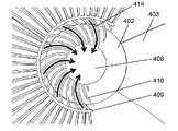
- FIG. 21 shows a front view of the front guard 407 and the axial flow fan 404 mounted on the upstream side, viewed from the downstream side, with a portion of the front guard 407 transmitted therethrough.
- the outer diameter of the guard mark 408 is smaller than the outer diameter of the hub 402 attached to the central portion of the axial fan 404.
- the outer diameter of the intermediate ring 409 is larger than the outer diameter of the hub 402 of the axial flow fan 404.
- FIGS. 22A and 22B the air flow blown from the portion near the hub 402 of the blade 403 of the axial flow fan 404 is induced to the central axis side of the axial flow fan 404 by the inner circumferential rib 410, and the vortex is suppressed.
- FIG. 22A is an enlarged view of the vicinity of the guard mark 408 of the front guard 407.
- the outer diameter of the intermediate ring 409 is larger than the outer diameter of the hub 402 of the axial flow fan 404. Therefore, the wind blown from the portion near the hub 402 of the blade 403 of the axial flow fan 404 passes between the inner circumferential ribs 410.
- FIG. 22B is a cross-sectional view of the front guard 407 and the axial fan 404 as viewed from the side.
- the wind having passed between the inner circumferential ribs 410 is guided to the central axis side and flows into the area downstream of the guard mark 408.
- an air flow 415 flowing into the area downstream of the guard mark 408 is formed.
- the area under negative pressure is reduced. Therefore, the volume of the air flowing into the area downstream of the guard mark 408 in the mainstream of the wind blown from the outer peripheral side of the blade 403 of the axial fan 404 decreases, and the vortex in the area downstream of the guard mark 408 Occurrence is suppressed.
- the reduction of the speed of the wind near the central axis after passing through the front guard 407 is suppressed, and the air can be efficiently blown.
- an outer peripheral rib 411 is formed between the intermediate ring 409 and the outer peripheral edge 412 of the front guard 407.
- the inner circumferential rib 410 and the outer circumferential rib 411 are each formed in an arc shape having a curvature.
- the curvature of the inner circumferential rib 410 is larger than the curvature of the outer circumferential rib 411.
- the airflow from the portion near the hub 402 of the blade 403 has a large rotational component, and is blown out radially outward in response to centrifugal force.
- the blade 403 provided in the axial fan 404 has a maximum wide portion 413 where the chord length is maximum.
- the outer circumferential rib 411 is provided to face the largest wide portion 413.
- the wind blown from the axial fan 404 is boosted by passing between the blades 403 of the axial fan 404.
- the amount of airflow boosted at the widest part 413 of the axial fan 404 is the largest in the distribution of the amount of airflow boosted by the axial fan 404.
- the velocity of the air flow boosted at the widest wide portion 413 of the axial fan 404 has a maximum value in the velocity distribution of the air blown by the axial fan 404.
- the high-velocity, high-speed air flow that has been boosted at the widest part 413 passes between the outer peripheral ribs 411.
- the outer circumferential rib 411 has a curvature smaller than that of the inner circumferential rib 410. Therefore, the high-speed air flow boosted at the widest part 413 has a direction closer to parallel to the central axis of the axial fan 404 than the air flow blown from a portion near the hub 402 of the blades 403 of the axial fan 404. Be blown out. That is, the air flow boosted at the largest wide portion 413 and the air flow with the largest wind speed are blown in a direction close to parallel to the central axis of the axial flow fan 404. This can improve the blowing efficiency.
- the conventional fan has a configuration described in, for example, Patent Document 4 (Japanese Patent Laid-Open No. 2015-108362) as a shape for improving the air flow performance of a guard mark located at the center of the front guard.
- FIG. 29 is a front view showing the configuration of the guard mark 51 used in the conventional fan
- FIG. 30 is a side view of the fan having the guard mark 51 attached to the center of the front guard 52.
- the guard mark 51 has an opening 53 communicating on the outer periphery side of the guard mark from the upstream side on the axial fan side to the downstream side to be the front side of the fan.
- the air flow blown from the vicinity of the hub of the axial flow fan is allowed to pass through the opening 53 to reduce the air flow resistance of the air flow from the axial flow fan and to increase the amount of air passing through the front guard 52.
- the guard mark 51 of such a conventional fan In the guard mark 51 of such a conventional fan, the air flow blown from the vicinity of the hub of the axial flow fan is blocked by the guard mark 51 on the downstream side of the guard mark 51. Therefore, a pressure difference occurs between the area through which the front guard 52 passes and the air flow generated by the axial fan is blown and the downstream area facing the guard mark 51, and as a result, the downstream area facing the guard mark 51 There is a negative pressure compared to the area where the air flow generated by the axial fan is blown.
- the main flow of the air flow of the axial fan generated on the outer peripheral side of the axial fan blade flows toward the area downstream of the guard mark 51 which is a negative pressure, and the axis downstream of the guard mark 51 It flows backward in the flow direction of the mainstream of the flow fan to generate a circulating flow. Due to the influence of the circulation flow, the main flow of the air flow of the axial flow fan generated on the outer peripheral side of the blades of the axial flow fan is attenuated.
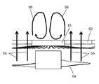
- FIG. 31 shows a cross-sectional view of the guard mark 51 in the conventional example, and conceptually shows the air flow 55 passing through the guard mark 51 and the circulating flow 56 generated in the region on the downstream side of the guard mark 51.
- the air flow 55 from the axial flow fan 54 is blown to the downstream side of the front guard 52.
- the air flow 55 from the axial flow fan 54 is blocked by the guard mark 51 and is not blown. Therefore, the downstream region of the guard mark 51 has a relatively negative pressure as compared to the downstream region facing the front guard 52 through which the air flow 55 passes and the downstream region of the guard mark 51.
- the air flow 55 from the axial flow fan 54 which has passed through the front guard 52 is attracted by the negative pressure in the downstream region of the guard mark 51 and is drawn in the direction of the central axis of the axial flow fan 54.
- a circulating flow 56 flowing toward the guard mark 51 is formed.
- the circulation flow 56 the main flow of the air flow by the axial flow fan 54 is attenuated, and the air blowing efficiency is deteriorated.
- the damping action of the main flow velocity of the air flow of the axial flow fan 54 is reduced by suppressing the circulation flow generated in the region downstream of the guard mark 51, and the air flow straight It aims to provide a fan that improves the quality.
- the fan according to the fifth embodiment of the present disclosure includes an axial fan having a plurality of blades and configured to blow air by rotation by a motor, and is provided upstream of the axial fan in the axial direction of the axial fan.
- Rear guard and a front guard provided on the downstream side in the axial direction of the axial fan than the rear guard, the front guard being parallel to the downstream surface and the downstream surface at the center of the front guard and larger than the downstream surface
- the guard mark has a frusto-conical guard mark having a diameter upstream face, the upstream face of the guard mark faces the axial fan, and the guard mark is an outer edge of the downstream face of the guard mark on the downstream face of the guard mark And an annular groove arranged along the
- the axial fan further includes a hub provided with a plurality of blades, and the diameter of the upstream surface of the guard mark is greater than the diameter of the axial fan hub. It may also be made smaller. With this configuration, the air flow pressurized by the portion of the blade near the hub is prevented from being blocked by the upstream surface of the guard mark. Therefore, the air flow resistance generated when the air flow pressurized by the portion located in the vicinity of the hub of the blade is blown to the downstream side of the guard mark is reduced, and the air flow from the axial flow fan can be efficiently blown.
- the annular groove may be formed concentrically with the downstream surface of the guard mark.
- the distance from the outer edge of the guard mark to the annular groove has a constant value over the entire circumference of the annular groove. Therefore, the vortices generated in the annular groove have the same size all around the groove. Therefore, the air flow blown from the axial fan is evenly attracted to the vortex formed by the annular groove all around the annular groove. Thereby, the turbulence of the air flow in the area
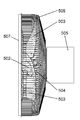
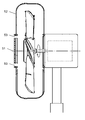
- FIG. 25 is a perspective view of the fan 501 according to the fifth embodiment of the present disclosure
- FIG. 26 is a side view of the fan 501
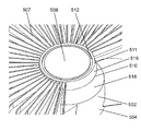
- FIG. 27 is a downstream side of the guard mark 508 of the front guard 507 of the fan 501. It is the perspective view seen from.
- the fan 501 includes an axial fan 504 having a plurality of blades 503 attached to a central hub 502, a motor (not shown) for rotating the axial fan 504, and an upstream side of the axial fan 504. And a motor housing 505 containing a motor provided therein.
- the fan 501 includes a rear guard 506 and a front guard 507.
- the rear guard 506 covers the axial fan 504 from the side and the back side that is the upstream side of the axial fan 504, and protects foreign matter from contacting the axial fan 504.
- the rear guard 506 is formed of a metal or resin wire.
- the front guard 507 covers from the front side, which is the downstream side of the axial fan 504, and protects the axial fan 504 from contact with foreign matter.
- the front guard 507 is formed of a metal or resin wire.
- the front guard 507 also includes a guard mark 508 provided at the center of the front guard 507.
- the front guard 507 is fixed to the rear guard 506 by an outer peripheral ring 509 located at the outermost periphery of the front guard 507.
- the size of the downstream surface of the hub 502 of the axial flow fan 504 is a size of a radius of 50 mm
- the size of the blades 503 is a size of a maximum radius of 250 mm.
- the guard mark 508 has a truncated cone shape having a circular upstream surface 510, a circular downstream surface 511, and a tapered side surface 519.
- the upstream surface 510 is parallel to the downstream surface 511.
- the upstream surface 510 faces the downstream surface 518 of the axial fan 504.
- the side surface 519 extends between the upstream surface 510 and the downstream surface 511.
- the diameter of the upstream surface 510 is larger than the diameter of the downstream surface 511.
- the guard mark 508 is provided with an annular groove 512 disposed on the downstream surface 511 along the outer edge of the circular downstream surface 511. A clearance of about 1 mm is provided between the outer edge of the downstream surface 511 and the annular groove 512.
- the upstream surface 510 has a radius of 50 mm
- the downstream surface 511 has a radius of 44.7 mm.
- the distance between the upstream surface 510 and the downstream surface 511 corresponding to the height of the truncated cone shape is 30 mm.
- the side surface 519 is inclined with respect to the central axis of the axial fan 504.
- the size of the groove 512 is 5 mm in depth and 5 mm in width.
- FIG. 28 shows a cross-sectional view of the guard mark 508 and further conceptually shows the air flow 513, the side air flow 514, the induced air flow 516, and the circulation flow 517.
- the blowing air flow 513 is an air flow that is pressurized by a portion of the blade 503 near the hub 502 and is blown in a direction parallel to the central axis of the axial flow fan 504. The blowing air 513 passes near the side surface 519 of the guard mark 508.
- a part of the air flow 513 is a side air flow 514 along the side surface 519 of the guard mark 508.
- the side air flow 514 peels off the side surface 519 at the edge portion of the guard mark 508 and is blown toward the center side of the guard mark 508.
- a part of the air flow blown toward the center side of the guard mark 508 is attracted into the annular groove 512 to form the vortex 515.
- the vortex 515 stays in the annular groove 512 and is constantly attracted to a part of the side air flow 514 to generate the induced air flow 516.
- the diameter of the downstream surface 518 of the hub 502 is larger than the diameter of the upstream surface 510 of the guard mark 508.
- the radius of the upstream surface 510 of the guard mark 508 is 50 mm.
- the radius of the downstream surface 518 of the hub 502 is 55 mm. Therefore, the blowing air flow 513 passes through the front guard 507 and flows downstream without colliding with the upstream surface 510 of the guard mark 508. Therefore, the air flow resistance due to the air flow 513 colliding with the upstream surface 510 of the guard mark 508 can be reduced, and the air flow 513 can efficiently flow through the front guard 507 and flow downstream.
- the annular groove 512 forms a concentric circle with the circular downstream surface 511 of the guard mark 508. Therefore, the distance between the outer edge of the downstream surface 511 of the guard mark 508 and the groove 512 of the guard mark 508 has a constant value over the entire circumference of the groove 512. Also, the size of the vortex 515 is determined according to the distance from the outer edge of the downstream surface 511 of the guard mark 508. Therefore, the magnitudes of the vortices 515 are substantially equal throughout the entire circumference of the groove 512. Therefore, a part of air flow of the side air flow 514 can be equally attracted from the outer edge of the guard mark 508 to the downstream region of the guard mark 508 as the induced air flow 516. With such a configuration, it is possible to reduce the turbulent flow of the induced air flow 516, improve the blowing performance, and reduce the noise in the region downstream of the guard mark 508.
- the fan according to the present disclosure can suppress the resistance of the flow drawn by the axial fan, and can improve the straightness of the wind, so it can be attached to the wall of a large space such as a living room, a meeting room, or a dining room Is useful as a fan to get a cool feeling.
Abstract
This fan is provided with: an axial flow fan which blows wind; a front guard provided on the downstream side of the axial flow fan; an inner ring (110) which partitions the front guard into an inner circumferential-side ventilation part and an outer circumferential-side ventilation part; and an outer ring (111) formed outside the inner ring (110). An inner rectification plate (112) protruding in the rotation direction of the axial flow fan is provided between the inner ring (110) and a guard mark (107) at the center of the inner ring (110). The inner rectification plate (112) includes an inner rectification plate-inclined part (113) which is inclined toward the rotation direction of the axial flow fan from a first end on the upstream-side in the rotation direction of the axial flow fan. An outer rectification plate (114) is formed between the inner ring (110) and the outer ring (111), and the outer rectification plate (114) includes an outer rectification plate-inclined part which is inclined toward the opposite direction as the rotation direction of the axial flow fan from a second end on the upstream-side in the rotation direction of the axial flow fan.
Description
本開示は、居室内の天井や壁、床面等に設置されて直接気流による体感温度の減少や室内の空気の循環に使用される扇風機に関するものである。
The present disclosure relates to a fan that is installed on a ceiling, a wall, a floor surface, or the like in a living room and used to reduce a sensible temperature due to direct air flow and to circulate indoor air.
従来この種の扇風機は、風の直進性の向上を目的としたものとして、例えば、特許文献1に記載されている構成が示されている。以下、その構成について、図5、6を参照しながら説明する。
Conventionally, for this type of fan, for example, a configuration described in Patent Document 1 is shown as an object for improving the straightness of the wind. The configuration will be described below with reference to FIGS.
図5は、従来の扇風機の構成を示す斜視図であり、図6は、軸流ファン11の下流側に設けられたフロントガード12の形状を示す斜視図である。図5に示すように、フロントガード12は、軸流ファン11から送風される風が通過する通風部13と、その外周に、リアガード14とフロントガード12とを位置決めして固定するためのガードリング15を有している。通風部13は、図6に示すように、フロントガード12の中央側からガードリング15に向かって伸びる整流板17が軸流ファン11の回転軸を軸対称として渦巻状に設けられている。そして整流板17のうち一部は、その中央側が軸流ファン11の回転軸方向の上流側に突出した形状となっている。
FIG. 5 is a perspective view showing the configuration of a conventional fan, and FIG. 6 is a perspective view showing the shape of a front guard 12 provided on the downstream side of the axial flow fan 11. As shown in FIG. 5, the front guard 12 is a guard ring for positioning and fixing the rear guard 14 and the front guard 12 on the outer periphery of the ventilation portion 13 through which the wind blown from the axial flow fan 11 passes. There are fifteen. As shown in FIG. 6, the ventilation portion 13 is provided with a straightening vane 17 extending from the center side of the front guard 12 toward the guard ring 15 in a spiral shape such that the rotation axis of the axial flow fan 11 is axially symmetrical. A part of the straightening vane 17 has a shape in which the center side thereof protrudes upstream in the rotational axis direction of the axial flow fan 11.
このような従来の扇風機のフロントガードは、軸流ファンから送風された風を、整流板に沿わせて中央に集めて風の直進性を高めていた。しかしながら、上記フロントガードは、風の直進性を十分に得ることができない。軸流ファンの外周側の羽根近傍では、吹き出す方向の気流が発生する。軸流ファンの外周の羽根間では、吸い込む方向の気流が発生する。上記整流板は、この吸い込む方向の気流を考慮した形状にはなっていない。むしろ上記整流板は、軸流ファンの外周側の吸い込む方向の気流に対しては、抵抗になっていたため、軸流ファンの外周側での気流の流れを乱す要因となる。その結果、気流の主流を拡散させてしまい、風の直進性を十分に得ることができない。そこで、本開示は、吸い込む方向の気流が受ける抵抗を抑制し、風の直進性を向上させる扇風機を提供することを目的とする。
The front guard of such a conventional fan has enhanced the straightness of the wind by collecting the wind blown from the axial fan along the straightening vane at the center. However, the front guard can not sufficiently obtain the straightness of the wind. In the vicinity of the blades on the outer peripheral side of the axial fan, an air flow in the blowing direction is generated. An air flow in the suction direction is generated between the outer peripheral blades of the axial flow fan. The straightening vane is not shaped in consideration of the air flow in the suction direction. Rather, the straightening plate resists the air flow in the suction direction on the outer peripheral side of the axial flow fan, and thus causes disturbance of the air flow on the outer peripheral side of the axial flow fan. As a result, the mainstream of the air flow is diffused, and the straightness of the wind can not be obtained sufficiently. Therefore, the present disclosure aims to provide a fan that suppresses the resistance to the air flow in the suction direction and improves the straightness of the wind.
そして、この目的を達成するために、本開示のある態様の扇風機は、複数枚の羽根を有し回転により風を送風する軸流ファンと、軸流ファンよりも軸流ファンの回転軸方向の下流側に設けられたフロントガードと、を備える。フロントガードは、内側リングと、内側リングの外側に、内側リングと間を空けて内側リングと同心円に設けられた外側リングと、内側リングの中央に、内側リングと間を空けて設けられた円盤状のガードマークと、ガードマークと内側リングとの間に設けられた、複数の内側整流板と、内側リングと外側リングとの間に設けられた複数の外側整流板と、を備える。複数の内側整流板の各々は、軸流ファンの回転方向に向かって突出する円弧状に形成されている。複数の内側整流板の各々は、軸流ファンの回転軸方向の上流側の第1端部を有する内側整流板傾斜部を含む。内側整流板傾斜部は、第1端部から軸流ファンの回転方向に向かうように傾斜している。複数の外側整流板の各々は、軸流ファンの回転軸方向の上流側の第2端部を有する外側整流板傾斜部を含む。外側整流板傾斜部は、第2端部から軸流ファンの回転方向とは反対の方向に向かうように傾斜している。
And in order to achieve this object, the fan according to an embodiment of the present disclosure includes an axial fan having a plurality of blades for blowing air by rotation, and an axial fan in the axial direction of the axial fan rather than the axial fan. And a front guard provided on the downstream side. The front guard is a disk provided with an inner ring, an outer ring provided on the outer side of the inner ring, an outer ring concentric with the inner ring and an inner ring, and a disk provided in the center of the inner ring and an inner ring. Guard marks, a plurality of inner baffles provided between the guard marks and the inner ring, and a plurality of outer baffles provided between the inner ring and the outer ring. Each of the plurality of inner straightening vanes is formed in an arc shape projecting in the rotational direction of the axial fan. Each of the plurality of inner baffles includes an inner baffle slope having a first end upstream of the axial fan in the rotational axis direction. The inner straightening vane slope is inclined from the first end toward the rotational direction of the axial fan. Each of the plurality of outer baffles includes an outer baffle slope having a second end upstream of the axial fan in the rotational axis direction. The outer straight baffle slope is inclined from the second end in a direction opposite to the rotational direction of the axial fan.
本開示の上記態様によれば、吸い込む方向の気流が受ける抵抗を抑制し、風の直進性を向上させる扇風機を提供できる。
According to the above aspect of the present disclosure, it is possible to provide a fan that suppresses the resistance to the air flow in the suction direction and improves the straightness of the wind.
(実施の形態1)
本開示の実施の形態1に係る扇風機は、複数枚の羽根を有し回転により風を送風する軸流ファンと、軸流ファンよりも軸流ファンの回転軸方向の下流側に設けられたフロントガードと、を備える。フロントガードは、内側リングと、内側リングの外側に、内側リングと間を空けて内側リングと同心円に設けられた外側リングと、内側リングの中央に、内側リングと間を空けて設けられた円盤状のガードマークと、ガードマークと内側リングとの間に設けられた複数の内側整流板と、内側リングと外側リングとの間に設けられた複数の外側整流板と、を備える。複数の内側整流板の各々は、軸流ファンの回転方向に向かって突出する円弧状に形成される。複数の内側整流板の各々は、軸流ファンの回転軸方向の上流側の第1端部を有する内側整流板傾斜部を含む。内側整流板傾斜部は、第1端部から軸流ファンの回転方向に向かうように傾斜している。複数の外側整流板の各々は、軸流ファンの回転軸方向の上流側の第2端部を有する外側整流板傾斜部を含む。外側整流板傾斜部は、第2端部から軸流ファンの回転方向とは反対側の方向に向かうように傾斜している。Embodiment 1
The fan according to the first embodiment of the present disclosure includes an axial fan having a plurality of blades for blowing air by rotation, and a front provided downstream of the axial fan in the axial direction of the axial fan. And a guard. The front guard is a disk provided with an inner ring, an outer ring provided on the outer side of the inner ring, an outer ring concentric with the inner ring and an inner ring, and a disk provided in the center of the inner ring and an inner ring. Guard marks, a plurality of inner baffles provided between the guard marks and the inner ring, and a plurality of outer baffles provided between the inner ring and the outer ring. Each of the plurality of inner straightening vanes is formed in an arc shape projecting in the rotational direction of the axial fan. Each of the plurality of inner baffles includes an inner baffle slope having a first end upstream of the axial fan in the rotational axis direction. The inner straightening vane slope is inclined from the first end toward the rotational direction of the axial fan. Each of the plurality of outer baffles includes an outer baffle slope having a second end upstream of the axial fan in the rotational axis direction. The outer straight baffle slope is inclined from the second end in a direction opposite to the rotational direction of the axial fan.
本開示の実施の形態1に係る扇風機は、複数枚の羽根を有し回転により風を送風する軸流ファンと、軸流ファンよりも軸流ファンの回転軸方向の下流側に設けられたフロントガードと、を備える。フロントガードは、内側リングと、内側リングの外側に、内側リングと間を空けて内側リングと同心円に設けられた外側リングと、内側リングの中央に、内側リングと間を空けて設けられた円盤状のガードマークと、ガードマークと内側リングとの間に設けられた複数の内側整流板と、内側リングと外側リングとの間に設けられた複数の外側整流板と、を備える。複数の内側整流板の各々は、軸流ファンの回転方向に向かって突出する円弧状に形成される。複数の内側整流板の各々は、軸流ファンの回転軸方向の上流側の第1端部を有する内側整流板傾斜部を含む。内側整流板傾斜部は、第1端部から軸流ファンの回転方向に向かうように傾斜している。複数の外側整流板の各々は、軸流ファンの回転軸方向の上流側の第2端部を有する外側整流板傾斜部を含む。外側整流板傾斜部は、第2端部から軸流ファンの回転方向とは反対側の方向に向かうように傾斜している。
The fan according to the first embodiment of the present disclosure includes an axial fan having a plurality of blades for blowing air by rotation, and a front provided downstream of the axial fan in the axial direction of the axial fan. And a guard. The front guard is a disk provided with an inner ring, an outer ring provided on the outer side of the inner ring, an outer ring concentric with the inner ring and an inner ring, and a disk provided in the center of the inner ring and an inner ring. Guard marks, a plurality of inner baffles provided between the guard marks and the inner ring, and a plurality of outer baffles provided between the inner ring and the outer ring. Each of the plurality of inner straightening vanes is formed in an arc shape projecting in the rotational direction of the axial fan. Each of the plurality of inner baffles includes an inner baffle slope having a first end upstream of the axial fan in the rotational axis direction. The inner straightening vane slope is inclined from the first end toward the rotational direction of the axial fan. Each of the plurality of outer baffles includes an outer baffle slope having a second end upstream of the axial fan in the rotational axis direction. The outer straight baffle slope is inclined from the second end in a direction opposite to the rotational direction of the axial fan.
これにより、各内側整流板は、吹き出し気流に沿うように傾斜する。そのため、吹き出し気流がフロントガードから受ける抵抗を低減できる。加えて、各内側整流板は、軸流ファンの回転方向に向かって突出する円弧状に形成されている。これにより、吹き出し気流を中央へ集める。また、各外側整流板は、羽根の外周側で発生する軸流ファンの回転方向に沿った吸い込み気流に沿うように傾斜している。そのため、吸い込み気流がフロントガードから受ける抵抗を低減することができる。これにより、軸流ファンの外周側での気流の乱れを低減することができる。これらの結果、本開示の実施の形態1に係る扇風機は、軸流ファンの中央へ集めた吹き出し気流の拡散を抑制し、風の直進性を向上させることで、遠くまで送風することができる。
Thereby, each inner side straightening vane inclines along blowoff air current. Therefore, the resistance which blowing air flow receives from a front guard can be reduced. In addition, each inner straightening vane is formed in an arc shape projecting in the rotational direction of the axial fan. Thus, the blowing air flow is collected to the center. Further, each outer straightening vane is inclined along the suction air flow along the rotational direction of the axial fan generated on the outer peripheral side of the blade. Therefore, the resistance of the suction air flow from the front guard can be reduced. Thereby, the turbulence of the air flow on the outer peripheral side of the axial fan can be reduced. As a result of these, the fan according to the first embodiment of the present disclosure can blow air far by suppressing the diffusion of the blown air collected to the center of the axial fan and improving the straightness of the wind.
また、本開示の実施の形態1に係る扇風機において、複数の内側整流板の各々は、内側整流板傾斜部よりも軸流ファンの回転軸方向の下流側に設けられ、軸流ファンの回転軸方向に沿った内側整流板直線部をさらに含み、内側整流板傾斜部は、軸流ファンの回転軸方向の下流側の第3端部をさらに有し、第3端部において内側整流板直線部と連結されていることとしてもよい。この構成により、本開示の実施の形態1に係る扇風機は、風の直進性を向上させ遠くまで送風することができる。具体的には、軸流ファンの回転により送風された風は、旋回成分を有する。内側整流板直線部は、風の旋回成分を回転軸方向成分に変換する。これにより、風の直進性をさらに向上することができる。
Further, in the fan according to the first embodiment of the present disclosure, each of the plurality of inner straightening vanes is provided downstream of the inner straightening vane inclined portion on the downstream side in the axial direction of the axial fan and the rotary shaft of the axial fan The inner straightening plate straight section further includes a third straight end on the downstream side in the axial direction of the axial flow fan, and the inner straight straightening section at the third end. It may be connected with With this configuration, the fan according to the first embodiment of the present disclosure can improve the straightness of the wind and can blow the air far. Specifically, the wind blown by the rotation of the axial fan has a swirl component. The inner straightening plate linear portion converts a swirl component of the wind into a rotational axis component. Thereby, the straightness of the wind can be further improved.
また、本開示の実施の形態1に係る扇風機において、複数の内側整流板の各々は、内側整流板傾斜部と内側整流板直線部とを含む外周側の領域と、外周側の領域よりも内周側に位置しており、内側整流板傾斜部を含まず内側整流板直線部を含む内周側の領域とを有していることとしてもよい。この構成により、本開示の実施の形態1に係る扇風機は、フロントガードを正面から見たときのガードマークから内側整流板の所定の位置までの中心付近(内周側の領域)における通風面積を増やすことができる。そのため、ガードマーク近傍の中心付近(内周側の領域)における圧力損失を低減することができ、中心付近の風速を向上させ遠くまで送風することができる。
Further, in the fan according to the first embodiment of the present disclosure, each of the plurality of inner straightening vanes is more inward than the outer circumferential side region including the inner straightening vane inclined portion and the inner straightening vane straight portion and the outer circumferential side region. It may be located on the circumferential side, and may have a region on the inner circumferential side including the inner straightening vane straight portion without including the inner straightening vane inclined portion. With this configuration, the fan according to Embodiment 1 of the present disclosure has a ventilation area in the vicinity of the center (region on the inner circumferential side) from the guard mark when the front guard is viewed from the front to a predetermined position of the inner straightening vane. It can be increased. Therefore, the pressure loss near the center (region on the inner circumferential side) near the guard mark can be reduced, and the wind speed near the center can be improved and the air can be blown far.
また、本開示の実施の形態1に係る扇風機において、内側整流板傾斜部と内側整流板直線部とが成す内側整流板傾斜角が最小となる位置は、内側リングの半径の中点よりも外周側の位置にあることとしてもよい。この構成により、本開示の実施の形態1に係る扇風機は、風速を向上させることができ、遠くまで風を届かせることができる。風の旋回成分は、フロントガードの半径方向に速度分布を有する。軸流ファン外周側では、風の旋回成分の速度が速い。上記フロントガードは、そのような旋回成分の速度の速い風を内側整流板に沿って流すことができる。これにより圧力損失を低減して、風速を向上させることができる。
Further, in the fan according to the first embodiment of the present disclosure, the position at which the inner straightening vane inclination angle formed by the inner straightening vane inclined portion and the inner straight straightening vane portion is the smallest is the outer circumference than the middle point of the radius of the inner ring. It may be in the side position. With this configuration, the fan according to the first embodiment of the present disclosure can improve the wind speed and can make the wind reach far. The swirl component of the wind has a velocity distribution in the radial direction of the front guard. On the outer peripheral side of the axial fan, the speed of the swirling component of the wind is high. The front guard can flow such a high speed wind of a swirling component along the inner baffle. Thereby, the pressure loss can be reduced and the wind speed can be improved.
以下、本開示の実施の形態1について詳細に説明をする。
Hereinafter, the first embodiment of the present disclosure will be described in detail.
図1は、本開示の実施の形態1に係る扇風機の斜視図であり、図2は、図1の扇風機の側面図である。
FIG. 1 is a perspective view of a fan according to a first embodiment of the present disclosure, and FIG. 2 is a side view of the fan of FIG.
図1及び図2を用いて実施の形態1に係る扇風機101について説明する。扇風機101は、複数枚の羽根102を有した軸流ファン103と、軸流ファン103を回転させるためのモータ(図示せず)と、軸流ファン103の回転軸方向の上流側に設けられたモータを内包するモータハウジング104とで構成されている。
The fan 101 which concerns on Embodiment 1 is demonstrated using FIG.1 and FIG.2. The fan 101 includes an axial fan 103 having a plurality of blades 102, a motor (not shown) for rotating the axial fan 103, and an upstream side of the axial fan 103 in the rotational axis direction. It is comprised with the motor housing 104 which includes a motor.
また、扇風機101は、リアガード105と、フロントガード106とを備える。リアガード105は、軸流ファン103を側面側および軸流ファン103の回転軸方向の上流側である背面側から覆い異物が軸流ファン103に接触しないように保護する。フロントガード106は、軸流ファン103の回転軸方向の下流側である正面側から軸流ファン103を覆い軸流ファン103に異物が接触しないように保護する。また、フロントガード106は、中央に円盤状のガードマーク107を備える。
The fan 101 further includes a rear guard 105 and a front guard 106. The rear guard 105 covers the axial fan 103 from the side face side and the back side which is the upstream side in the axial direction of the axial fan 103 so as to protect foreign matter from contacting the axial fan 103. The front guard 106 covers the axial flow fan 103 from the front side, which is the downstream side of the axial flow fan 103 in the rotation axis direction, and protects the axial flow fan 103 from contact with foreign matter. In addition, the front guard 106 is provided with a disk-like guard mark 107 at the center.
また、フロントガード106は、ガードマーク107よりも外周側に位置する内周側通風部108と、内周側通風部108よりも外周側に位置する外周側通風部109とを備える。内周側通風部108は、主に、軸流ファン103より送風される風を通過させる。外周側通風部109は、主に、軸流ファン103の回転により、軸流ファン103の羽根102の外周側から軸流ファン103の回転方向に沿って誘引される風を通過させる。フロントガード106は、ガードマーク107と間を空けて設けられた内側リング110と、ガードマーク107と内側リング110との間に設けられた複数の内側整流板112と、を備える。内周側通風部108と外周側通風部109とは、円環状に形成された内側リング110によって仕切られている。また、フロントガード106は、内側リング110よりも外側に内側リング110と間を空けて設けられた、外側リング111と、内側リング110と外側リング111との間に設けられた複数の外側整流板114と、を備える。外側リング111は、円環状に形成され、内側リング110と同心円に設けられている。また、フロントガード106は、外側リング111によってリアガード105に固定されている。
Further, the front guard 106 includes an inner circumferential ventilation portion 108 positioned on the outer circumferential side than the guard mark 107 and an outer circumferential ventilation portion 109 positioned on the outer circumferential side than the inner circumferential ventilation portion 108. The inner side ventilation part 108 mainly allows the wind blown by the axial fan 103 to pass. The outer circumferential ventilation portion 109 mainly passes the wind induced along the rotational direction of the axial fan 103 from the outer circumferential side of the blades 102 of the axial fan 103 by the rotation of the axial fan 103. The front guard 106 includes an inner ring 110 spaced apart from the guard mark 107 and a plurality of inner straightening vanes 112 provided between the guard mark 107 and the inner ring 110. The inner circumferential ventilation portion 108 and the outer circumferential ventilation portion 109 are separated by an inner ring 110 formed in an annular shape. Also, the front guard 106 is provided on the outer side of the inner ring 110 so as to be spaced apart from the inner ring 110, and a plurality of outer straightening vanes provided between the inner ring 110 and the outer ring 111. And 114. The outer ring 111 is formed in an annular shape and provided concentrically with the inner ring 110. The front guard 106 is fixed to the rear guard 105 by an outer ring 111.
図1に示すように、複数の内側整流板112の各々は、ガードマーク107の側面と内側リング110の内周側の側面とを連結するように配設されている。複数の内側整流板112は、ガードマーク107の側面から内側リング110の内周側の側面に向かって放射するように形成されている。内周側通風部108は、隣接する内側整流板112およびガードマーク107の側面、内側リング110の内周側の側面とで区画された領域である。
As shown in FIG. 1, each of the plurality of inner flow straightening plates 112 is arranged to connect the side surface of the guard mark 107 and the side surface on the inner peripheral side of the inner ring 110. The plurality of inner flow straightening plates 112 are formed to radiate from the side surface of the guard mark 107 toward the inner peripheral side surface of the inner ring 110. The inner circumferential ventilation portion 108 is a region defined by the side surfaces of the adjacent inner straightening vanes 112 and the guard marks 107 and the inner peripheral side surface of the inner ring 110.
さらに、軸流ファン103より送風された風を軸流ファン103の中心に集中させるようにするため、内側整流板112は、軸流ファン103(羽根102)の回転方向に向かって突出する円弧状に形成されている。具体的には、内側整流板112は、ガードマーク107の側面に連結される第1連結部と、内側リング110の内周側の側面に連結される第2連結部と、第1連結部と第2連結部の間に位置する中央部分とを有する。内側整流板112の中央部分は、第1連結部と第2連結部とを結んだ直線に対して、軸流ファン103の回転方向に向かって突出するように形成されている。内側整流板112は、詳しくは後述するが、図3Bに示すように、内側整流板傾斜部113を含む。内側整流板傾斜部113は、内側整流板112における軸流ファン103の回転軸方向の上流側の第1端部X1から軸流ファン103の回転方向に向かうように傾斜している。内側整流板傾斜部113は、軸流ファン103によって送風される風が内周側通風部108を低抵抗で通過することを可能とする。
Furthermore, in order to concentrate the air blown by the axial fan 103 at the center of the axial fan 103, the inner straightening vane 112 has an arc shape projecting in the rotational direction of the axial fan 103 (vanes 102). Is formed. Specifically, the inner straightening vane 112 includes a first connecting portion connected to the side surface of the guard mark 107, a second connecting portion connected to the side surface on the inner peripheral side of the inner ring 110, and a first connecting portion. And a central portion located between the second coupling portions. A central portion of the inner straightening vane 112 is formed to project in the rotational direction of the axial flow fan 103 with respect to a straight line connecting the first connecting portion and the second connecting portion. The inner straightening vane 112, as will be described in detail later, includes an inner straightening vane slope 113, as shown in FIG. 3B. The inner straightening vane inclined portion 113 is inclined toward the rotational direction of the axial flow fan 103 from the first end X 1 on the upstream side in the rotational axial direction of the axial flow fan 103 in the inner straightening plate 112. The inner straightening vane inclined portion 113 enables the wind blown by the axial fan 103 to pass through the inner circumferential ventilation portion 108 with low resistance.
図1に示すように、複数の外側整流板114の各々は、内側リング110の外周側の側面と外側リング111の内周側の側面とを連結するように配設されている。複数の外側整流板114は、内側リング110の外周側の側面から外側リング111の内周側の側面に向かって放射するように形成されている。外周側通風部109は、隣接する外側整流板114および内側リング110の外周側の側面、外側リング111の内周側の側面とで区画された領域である。外側整流板114は、詳しくは後述するが、図4Aに示すように、外側整流板傾斜部114aを有する構成となっている。外側整流板傾斜部114aは、外側整流板114における軸流ファン103の回転軸方向の上流側の第2端部Y1から軸流ファン103の回転方向とは反対側の方向に向かうように傾斜している。軸流ファン103の羽根102の外周側では、軸流ファン103(羽根102)の回転方向に沿う吸い込み気流が発生する。外側整流板傾斜部114aは、吸い込み気流が外周側通風部109を低抵抗で通過することを可能とする。
As shown in FIG. 1, each of the plurality of outer straightening vanes 114 is disposed to connect the side surface on the outer peripheral side of the inner ring 110 and the side surface on the inner peripheral side of the outer ring 111. The plurality of outer straightening vanes 114 are formed to radiate from the outer peripheral side surface of the inner ring 110 toward the inner peripheral side surface of the outer ring 111. The outer periphery side ventilation part 109 is the area | region divided by the side surface of the outer peripheral side of the outer side flow control plate 114 and the inner ring 110 which adjoins, and the side surface of the inner peripheral side of the outer ring 111. Although the outer side straightening vane 114 will be described in detail later, as shown in FIG. 4A, it is configured to have the outer side straightening vane inclined portion 114a. The outer straightening vane inclined portion 114a is inclined from the second end Y1 on the upstream side of the outer straightening vane 114 in the axial direction of the axial flow fan 103 to the direction opposite to the rotational direction of the axial fan 103. ing. On the outer peripheral side of the blade 102 of the axial flow fan 103, suction air flow is generated along the rotation direction of the axial flow fan 103 (blade 102). The outer baffle plate inclined portion 114 a allows the suctioned air flow to pass through the outer circumferential ventilation portion 109 with low resistance.
本開示の実施の形態1に係る扇風機101によれば、各内側整流板112は、吹き出し気流に沿うように傾斜している。これにより、吹き出し気流がフロントガード106から受ける抵抗を低減する。各内側整流板112は、さらに、軸流ファン103の回転方向に向かって突出する円弧状に形成されている。このことにより、吹き出し気流が軸流ファン103の中央へ集められる。また、各外側整流板114は、吸い込み気流に沿うように傾斜している。そのため、吸い込み気流がフロントガード106から受ける抵抗を低減することができ、軸流ファン103の外周側での気流の乱れを低減する。これらの結果、扇風機101は、軸流ファン103の中央へ集めた吹き出し気流の拡散を抑制し、風の直進性を向上させることで、遠くまで送風することができる。
According to the fan 101 according to the first embodiment of the present disclosure, each inner straightening vane 112 is inclined along the blowout air flow. This reduces the resistance that the blowing air receives from the front guard 106. Each of the inner flow straightening plates 112 is further formed in an arc shape projecting in the rotation direction of the axial flow fan 103. As a result, the blown air is collected to the center of the axial fan 103. Further, each outer straightening vane 114 is inclined along the suction air flow. Therefore, the resistance of the suction air flow from the front guard 106 can be reduced, and the disturbance of the air flow on the outer peripheral side of the axial flow fan 103 can be reduced. As a result of these, the fan 101 can suppress the diffusion of the blown air collected to the center of the axial fan 103 and improve the straightness of the wind, whereby the fan can be blown far.
次に、フロントガード106を構成する内側整流板112および外側整流板114について説明する。
Next, the inner straightening plate 112 and the outer straightening plate 114 which constitute the front guard 106 will be described.
図3Aは、図1におけるA部分の拡大図であり、図3Bは、図3AにおけるB-B’断面における形状を示す断面図である。また、図4Aは、図3AにおけるC-C’断面における形状を示す断面図であり、図4Bは、図3AにおけるD-D’断面における形状を示す断面図である。なお、各断面図は、軸流ファン103の回転軸を中心とした円筒面で内側整流板112または外側整流板114を切断したときの断面(軸流ファン103の外周側から内周側を見た断面)を平面状に展開した図である。また、各断面図には、軸流ファン103(羽根102)を同様に切断したときの断面も含めている。
3A is an enlarged view of a portion A in FIG. 1, and FIG. 3B is a cross-sectional view showing the shape in the B-B 'cross section in FIG. 3A. 4A is a cross-sectional view showing the shape in the C-C 'cross section in FIG. 3A, and FIG. 4B is a cross-sectional view showing the shape in the D-D' cross section in FIG. 3A. Each cross-sectional view is a cross-sectional view of the inner straight plate 112 or the outer straight plate 114 cut along a cylindrical surface centered on the rotation axis of the axial flow fan 103 (from the outer circumferential side of the axial flow fan 103 to the inner circumferential side Cross section) in a planar form. Each cross-sectional view also includes a cross section obtained by similarly cutting the axial flow fan 103 (blade 102).
図3Aに示すように、複数の内側整流板112の各々は、ガードマーク107の側面と内側リング110の内周側の側面とを連結するように配設されている。複数の内側整流板112は、ガードマーク107の側面から内側リング110の内周側の側面に向かって放射するように形成されている。また、内側整流板112は、軸流ファン103の回転方向に向かって突出する円弧状に形成されている。さらに、複数の外側整流板114の各々は、内側リング110の外周側の側面と外側リング111の内周側の側面とを連結するように配設されている。複数の外側整流板114は、内側リング110の外周側の側面から外側リング111の内周側の側面に向かって放射するように形成されている。
As shown in FIG. 3A, each of the plurality of inner flow straightening plates 112 is disposed to connect the side surface of the guard mark 107 and the side surface on the inner peripheral side of the inner ring 110. The plurality of inner flow straightening plates 112 are formed to radiate from the side surface of the guard mark 107 toward the inner peripheral side surface of the inner ring 110. Further, the inner straightening vane 112 is formed in an arc shape projecting in the rotation direction of the axial flow fan 103. Furthermore, each of the plurality of outer flow straightening plates 114 is arranged to connect the outer peripheral side surface of the inner ring 110 and the inner peripheral side surface of the outer ring 111. The plurality of outer straightening vanes 114 are formed to radiate from the outer peripheral side surface of the inner ring 110 toward the inner peripheral side surface of the outer ring 111.
図3Bに示すように、内側整流板112は、内側整流板傾斜部113を有する。内側整流板傾斜部113は、軸流ファン103の回転軸方向の上流側の第1端部X1および軸流ファン103の回転軸方向の下流側の第3端部X2を有する。内側整流板傾斜部113は、第1端部X1から軸流ファン103の回転方向に向かうように傾斜する。すなわち、第3端部X2は、第1端部X1から見て軸流ファン103の回転方向に位置する。内側整流板112は、さらに内側整流板直線部115を有する。内側整流板直線部115は、内側整流板傾斜部113よりも軸流ファン103の回転軸方向の下流側に設けられ、軸流ファン103の回転軸方向に沿っている。内側整流板傾斜部113は、軸流ファン103の回転軸方向の下流側の第3端部X2において内側整流板直線部115と連結されている。
As shown in FIG. 3B, the inner straightening vane 112 has an inner straightening vane ramp 113. The inner straightening vane inclined portion 113 has a first end X1 on the upstream side in the rotational axis direction of the axial flow fan 103 and a third end X2 on the downstream side in the rotational axis direction of the axial flow fan 103. The inner straightening vane inclined portion 113 inclines in the rotation direction of the axial fan 103 from the first end X1. That is, the third end X2 is located in the rotation direction of the axial fan 103 as viewed from the first end X1. The inner straightening vane 112 further has an inner straightening vane straight portion 115. The inner straightening vane linear portion 115 is provided downstream of the inner straightening vane inclined portion 113 in the axial direction of the axial flow fan 103 and extends in the axial direction of the axial flow fan 103. The inner straightening vane inclined portion 113 is connected to the inner straightening vane straight portion 115 at the third end X 2 on the downstream side in the rotation axis direction of the axial flow fan 103.
図4Aに示すように、外側整流板114は、外側整流板傾斜部114aを有する。外側整流板傾斜部114aは、軸流ファン103の回転軸方向の上流側の第2端部Y1および軸流ファン103の回転軸方向の下流側の第4端部Y2を有する。外側整流板傾斜部114aは、第2端部Y1から軸流ファン103の回転方向とは反対側の方向に向かうように傾斜する。すなわち、第4端部Y2は、第2端部Y1から見て軸流ファン103の回転方向の反対の方向に位置する。なお、本実施の形態では、外側整流板傾斜部114aは、外側整流板114と同一の形状となっている。すなわち、外側整流板114における軸流ファン103の回転軸方向の上流側の端部は、第2端部Y1に一致する。外側整流板114における軸流ファンの103の回転軸方向の下流側の端部は、第4端部Y2に一致する。
As shown to FIG. 4A, the outer side baffle plate 114 has the outer side baffle plate inclined part 114a. The outer baffle plate inclined portion 114 a has a second end Y 1 on the upstream side in the rotational axis direction of the axial flow fan 103 and a fourth end Y 2 on the downstream side in the rotational axis direction of the axial flow fan 103. The outer baffle plate inclined portion 114 a inclines in a direction opposite to the rotational direction of the axial fan 103 from the second end Y 1. That is, the fourth end Y2 is located in the direction opposite to the rotational direction of the axial fan 103 as viewed from the second end Y1. In the present embodiment, the outer straightening vane inclined portion 114 a has the same shape as the outer straightening vane 114. That is, the end on the upstream side in the rotational axis direction of the axial flow fan 103 in the outer straightening vane 114 coincides with the second end Y1. The end on the downstream side in the rotational axis direction of the axial flow fan 103 in the outer straightening vane 114 coincides with the fourth end Y2.
図4Bに示すように、内側整流板112は、軸流ファン103の中心近傍(内周側の領域)において、軸流ファン103の回転軸方向に沿った内側整流板直線部115aを有する。軸流ファン103の中心近傍(内周側の領域)には、内側整流板傾斜部113は設けられていない。
As shown to FIG. 4B, the inner side straightening plate 112 has the inner side straightening plate linear part 115a along the rotation shaft direction of the axial flow fan 103 in the center vicinity (area | region of inner peripheral side) of the axial flow fan 103. As shown in FIG. The inner straightening vane inclined portion 113 is not provided in the vicinity of the center of the axial flow fan 103 (the region on the inner circumferential side).
軸流ファン103の回転により生成される風は、軸流ファン103の半径方向に風速分布を有する。すなわち、風速は、軸流ファン103の半径方向の位置に応じて異なる。軸流ファン103が、例えば、半径250mmの場合、軸流ファン103の下流側直近の半径方向の風速分布で風速の最大が、半径170mmの位置にある。最大風速を示す位置の近傍では、風の旋回成分の速度が大きくなる。そこで、図3Bに示すように、風の旋回成分の速度の大きな位置に内側整流板傾斜部113が設けられる。これにより最大風速をもつ風が内側整流板112の外周側の内側整流板傾斜部113に沿って流れることになり、風の乱れを低減することができる。
The wind generated by the rotation of the axial fan 103 has a wind speed distribution in the radial direction of the axial fan 103. That is, the wind speed differs depending on the radial position of the axial fan 103. For example, when the axial fan 103 has a radius of 250 mm, the maximum of the wind speed in the radial wind velocity distribution immediately downstream of the axial fan 103 is at a radius of 170 mm. Near the position showing the maximum wind speed, the speed of the swirling component of the wind is increased. Then, as shown to FIG. 3B, the inner side baffle plate inclination part 113 is provided in the position where the speed of the rotational component of a wind is large. As a result, the wind having the maximum wind velocity flows along the inner straightening vane inclined portion 113 on the outer circumferential side of the inner straightening vane 112, and wind disturbance can be reduced.
軸流ファン103からの風は、軸流ファン103の下流側直近において半径方向に風速分布を有する。軸流ファン103の周速は、軸流ファン103の中心に近いほど遅い。そのため、軸流ファン103の中心に近いほど風の旋回成分の速度も低下する。このため、内側整流板112は、軸流ファン103の中心近傍においては、内側整流板傾斜部113を含まず、図4Bに示すように、内側整流板直線部115aのみを含む。具体的には、内側整流板112は、内側リング110の半径が、例えば210mmのとき、内側リング110の中心から88mmの半径位置(内側リング110の中心から内側リング110の半径の約0.42倍の位置)までは、内側整流板直線部115aのみで形成される。内側整流板112は、この88mmの半径位置から風速の速い外周側である内側リング110までは、内側整流板直線部115および内側整流板傾斜部113を含む。すなわち、内側整流板112は、内側整流板直線部115aで構成される内周側の領域と、内側整流板傾斜部113と内側整流板直線部115とで構成される外周側の領域とを有している。これにより、内側整流板112が吹き出し気流に沿うように傾斜して、吹き出し気流がフロントガード106から受ける抵抗を低減することができる。
The wind from the axial fan 103 has a wind speed distribution in the radial direction immediately downstream of the axial fan 103. The circumferential speed of the axial fan 103 is slower as it approaches the center of the axial fan 103. Therefore, the closer to the center of the axial fan 103, the lower the speed of the swirling component of the wind. Therefore, the inner straightening vane 112 does not include the inner straightening vane inclined portion 113 near the center of the axial flow fan 103, and includes only the inner straightening vane straight portion 115a as shown in FIG. 4B. Specifically, when the radius of the inner ring 110 is, for example, 210 mm, the inner straightening vane 112 is located at a radius of 88 mm from the center of the inner ring 110 (about 0.42 of the radius of the inner ring 110 from the center of the inner ring 110). Up to the double position), only the inner straightening plate straight portion 115a is formed. The inner straightening vane 112 includes an inner straightening vane straight portion 115 and an inner straightening vane inclined portion 113 from the 88 mm radius position to the inner ring 110 on the outer peripheral side where the wind speed is high. That is, the inner straightening vane 112 has a region on the inner circumferential side constituted by the inner straightening vane straight portion 115 a and a region on the outer circumferential side constituted by the inner straightening vane inclined portion 113 and the inner straightening vane straight portion 115 doing. As a result, the inner straightening vane 112 is inclined along the blowout air flow, and the resistance of the blowout air flow from the front guard 106 can be reduced.
また、内側整流板112は、図1および図3Aに示すように、軸流ファン103の回転方向に向かって突出する円弧状に形成されている。このことにより、吹き出し気流を軸流ファン103の中心へ集中させることができ、風速を増加させて、遠くまで送風することが可能となる。
Further, as shown in FIGS. 1 and 3A, the inner straightening vane 112 is formed in an arc shape that protrudes in the rotation direction of the axial flow fan 103. As a result, the blown air can be concentrated to the center of the axial fan 103, and the wind speed can be increased to blow the air far.
図4Aに示すように、外側整流板114は、吸い込み気流に沿うように傾斜している。これにより、吸い込み気流が外周側通風部109を通過する際の抵抗を低減することができ、軸流ファン103の外周側での気流の乱れを低減することができる。この結果、軸流ファン103の中央へ集められた吹き出し気流の拡散を抑制し、風の直進性を向上させることで、遠くまで風を届かせることができる。
As shown in FIG. 4A, the outer straightening vane 114 is inclined along the suction air flow. As a result, the resistance when the suctioned air flow passes through the outer peripheral ventilation portion 109 can be reduced, and the disturbance of the air flow on the outer peripheral side of the axial flow fan 103 can be reduced. As a result, by suppressing the diffusion of the blown air collected to the center of the axial fan 103 and improving the straightness of the wind, the wind can be made to reach far.
風は、軸流ファン103の回転により生成されるため、旋回成分をもつ。この風の旋回成分が下流側に流れるに従い拡散して風の直進性を悪化させる要因となっている。図3Bに示すように、内側整流板112は、内側整流板傾斜部113よりも下流側に軸流ファン103の回転軸と平行となる面で形成された内側整流板直線部115を有する。この内側整流板直線部115によって、風の旋回成分を軸流ファン103の回転軸方向成分に変換することができる。そのため、軸流ファン103の中央へ集められた吹き出し気流の拡散を抑制し、風の直進性を向上させることで、遠くまで風を届かせることができる。
The wind is generated by the rotation of the axial fan 103 and therefore has a swirl component. The swirling component of the wind is diffused as it flows downstream, which causes the straightness of the wind to deteriorate. As shown to FIG. 3B, the inner side straightening plate 112 has the inner side straightening plate linear part 115 formed in the surface which becomes parallel to the rotating shaft of the axial flow fan 103 in the downstream rather than the inner side straightening plate inclination part 113. FIG. The inner straightening plate linear portion 115 can convert a swirling component of the wind into a component in the axial direction of the axial flow fan 103. Therefore, by suppressing the diffusion of the blown air collected to the center of the axial fan 103 and improving the straightness of the wind, the wind can be made to reach far.
軸流ファン103により生成される風は、軸流ファン103の下流側直近において、半径方向に風速分布を有する。つまり、風が最大風速を示す位置が存在する。軸流ファン103が、例えば、半径250mmの場合、最大風速を示す位置は、軸流ファン103の中心から170mmの位置にある。このとき、最大風速を示す位置の近傍では、旋回成分の速度が大きくなる。このため、内側整流板傾斜部113と内側整流板直線部115とのなす角、すなわち内側整流板傾斜角116(図3Bを参照)を小さくすることで、風を内側整流板傾斜部113に沿って流すことができる。内側整流板傾斜角116は、フロントガード106の半径方向に角度分布を有していてもよい。内側整流板傾斜角116が最小となる位置は、内側リング110の半径の中点よりも外周側の位置にあることとしてもよい。例えば、内側整流板傾斜部113は、内側リング110の中心から140mmから189mmの位置にある位置で内側整流板傾斜角116が最小角度となるように形成されている。すなわち、風の旋回成分が最大となる位置は、内側整流板傾斜角116が最小角度となる位置に一致する。これにより、風が内側整流板傾斜部113に沿い、旋回成分の風の乱れによる抵抗を低減することができる。これにより、軸流ファン103の外周側の周速度が速い部分からの風が内側整流板112に沿って流れるので、圧力損失を低減して風速を向上させることができ、遠くまで風を届かせることができる。
The wind generated by the axial fan 103 has a wind speed distribution in the radial direction immediately downstream of the axial fan 103. That is, there is a position where the wind shows the maximum wind speed. When the axial fan 103 has, for example, a radius of 250 mm, the position at which the maximum wind speed is indicated is 170 mm from the center of the axial fan 103. At this time, in the vicinity of the position indicating the maximum wind speed, the velocity of the turning component becomes large. Therefore, the wind is directed along the inner straightening vane slope 113 by reducing the angle formed by the inner straightening vane slope 113 and the inner straightening vane straight line portion 115, that is, the inner straightening vane slope angle 116 (see FIG. 3B). Can flow. The inner baffle inclination angle 116 may have an angular distribution in the radial direction of the front guard 106. The position at which the inner straightening vane inclination angle 116 is minimized may be located on the outer circumferential side of the middle point of the radius of the inner ring 110. For example, the inner straightening vane slope portion 113 is formed such that the inner straightening vane inclination angle 116 is a minimum at a position of 140 mm to 189 mm from the center of the inner ring 110. That is, the position where the swirling component of the wind is the maximum corresponds to the position where the inner straightening vane inclination angle 116 is the minimum angle. Thereby, the wind is along the inner straightening vane inclined portion 113, and the resistance due to the wind disturbance of the turning component can be reduced. As a result, the wind from the portion having a high peripheral speed on the outer peripheral side of the axial fan 103 flows along the inner straightening plate 112, so that the pressure loss can be reduced and the wind speed can be improved. be able to.
(実施の形態2)
従来の扇風機は、風の直進性の向上を目的としたものとして、例えば、特許文献1(実用新案登録第3196884号公報)に構成が示されている。 Second Embodiment
The configuration of a conventional fan is shown, for example, in Patent Document 1 (Utility Model Registration No. 3196884) as an object to improve the straightness of the wind.
従来の扇風機は、風の直進性の向上を目的としたものとして、例えば、特許文献1(実用新案登録第3196884号公報)に構成が示されている。 Second Embodiment
The configuration of a conventional fan is shown, for example, in Patent Document 1 (Utility Model Registration No. 3196884) as an object to improve the straightness of the wind.
以下、その構成について、図11および図12を参照しながら説明する。
The configuration will be described below with reference to FIGS. 11 and 12.
図11は従来の扇風機の構成を示す斜視図であり、図12は、軸流ファン21の下流側に設けられたフロントガード22の形状を示す斜視図である。図11に示すように、フロントガード22は、軸流ファン21から送風される風が通過する通風部23と、その外周に、リアガード24とフロントガード22とを位置決めして固定するためのガードリング25を有している。通風部23は、図12に示すようにフロントガード22の中央側からガードリング25に向かって伸びる整流板27が軸流ファン21の回転軸を軸対称として渦巻状に設けられている。そして整流板27のうち一部は、その中央側が軸流ファン21の回転軸方向上流側に突出した形状となっている。
FIG. 11 is a perspective view showing the configuration of a conventional fan, and FIG. 12 is a perspective view showing the shape of the front guard 22 provided on the downstream side of the axial flow fan 21. As shown in FIG. 11, the front guard 22 is a guard ring for positioning and fixing the rear guard 24 and the front guard 22 on the outer periphery of the ventilation portion 23 through which the wind blown from the axial flow fan 21 passes. It has 25. As shown in FIG. 12, the ventilation portion 23 is provided in a spiral shape in which a straightening plate 27 extending from the center side of the front guard 22 toward the guard ring 25 is axially symmetrical with respect to the rotation axis of the axial flow fan 21. A part of the straightening vane 27 has a shape in which the center side thereof protrudes to the upstream side of the axial flow fan 21 in the rotation axis direction.
このような従来の扇風機のフロントガード22は、軸流ファン21から送風された風を、一様厚さの整流板27に沿わせて中央に集めて風の直進性を高めている。フロントガード22は、さらに、複数枚の整流板27を密に配置し、各整流板27間の間隔を調整することでフロントガード22の各整流板27間への指入れを抑制していた。すなわち、フロントガード22の指入れを抑制するために、整流板27の枚数を増加させ、整流板27を密に配置する必要がある。しかしながら、整流板27の密な配置は、送風気流の抵抗の要因となり、送風性能の低下を招くという課題があった。そこで、本実施の形態は、フロントガードの各整流板27間への指入れを抑制し、送風性能が低下しない扇風機を提供することを目的する。
The front guard 22 of such a conventional fan improves the straightness of the wind by collecting the wind blown by the axial fan 21 along the straightening plate 27 of uniform thickness at the center. Furthermore, the front guard 22 closely arranges a plurality of flow straightening plates 27 and adjusts the distance between the flow straightening plates 27 to thereby suppress finger insertion between the flow straightening plates 27 of the front guard 22. That is, in order to suppress the insertion of the front guard 22, it is necessary to increase the number of the flow control plates 27 and to arrange the flow control plates 27 densely. However, the dense arrangement of the straightening vanes 27 is a factor of the resistance of the air flow, and there is a problem that the air flow performance is lowered. Therefore, the present embodiment aims to provide a fan that suppresses the insertion of a finger between the flow control plates 27 of the front guard and does not reduce the air blowing performance.
本開示の実施の形態2に係る扇風機は、複数枚の羽根を有し回転により風を送風する軸流ファンと、軸流ファンよりも軸流ファンの回転軸方向の下流側に設けられたフロントガードと、フロントガードよりも軸流ファンの回転軸方向の上流側に設けられたリアガードとを備え、フロントガードは、フロントガードの中央に設けられた円盤状のガードマークと、フロントガードの外周に設けられた外周リングと、ガードマークと外周リングとの間に設けられ、軸流ファンの回転方向の反対方向に向かって弧が閉じるように形成された円弧状の複数の整流板と、を備え、複数の整流板の各々は、軸流ファンで送風された気流の旋回方向に沿うように傾斜している整流板傾斜部と、整流板傾斜部よりも軸流ファンの回転軸方向の下流側に設けられた、軸流ファンの回転軸方向と平行な整流板直線部とを備え、整流板傾斜部は、羽根と対向する面を有し、この面は、隣接する他の整流板傾斜部に向かって突出する突出部を有するものである。
An electric fan according to a second embodiment of the present disclosure includes an axial fan having a plurality of blades for blowing air by rotation, and a front provided downstream of the axial fan in the axial direction of the axial fan. The guard includes a guard and a rear guard provided on the upstream side in the axial direction of the axial fan with respect to the front guard. The front guard includes a disk-shaped guard mark provided at the center of the front guard and the outer periphery of the front guard. And a plurality of arc-shaped straightening vanes provided between the guard mark and the outer circumferential ring, the arc-shaped straightening vanes being formed so that an arc is closed in a direction opposite to the rotational direction of the axial fan. And each of the plurality of straightening vanes is a straightening vane inclined portion which is inclined along the swirling direction of the air flow blown by the axial fan, and a downstream side in the axial direction of the axial fan from the straightening vane inclined portion. Provided in The straight-line portion parallel to the rotational axis direction of the axial fan, and the straight-line slope has a face facing the blade, and this face protrudes toward the other adjacent straight-line slope With a protruding portion.
整流板傾斜部の面に突出部が設けられたことで、隣接する整流板の整流板傾斜部間の間隔の最短距離が短くなる。そのため、フロントガードを通じて軸流ファンに向かって指が挿入されようとした場合であっても、隣接する整流板の整流板傾斜部の面の突出部によって、指がフロントガードを通過することを規制することができる。また、整流板傾斜部に突出部が設けられていることで、整流板直線部に突出部が設けられた場合と比較し、軸流ファンからの送風が受ける抵抗を低減し、送風性能低下を抑制することができる。
By providing the projecting portion on the surface of the straightening vane inclined portion, the shortest distance between the straightening vane inclined portions of the adjacent straightening vanes becomes short. Therefore, even if it is intended to insert a finger toward the axial fan through the front guard, the projection of the surface of the straightening plate inclined portion of the adjacent straightening vane restricts the finger from passing through the front guard. can do. In addition, since the projecting portion is provided in the straightening vane inclined portion, the resistance to the air flow from the axial flow fan is reduced and the air blowing performance is reduced compared to the case where the projecting portion is provided in the straightening vane straight portion. It can be suppressed.
また本開示の実施の形態2に係る扇風機において、整流板傾斜部は、軸流ファンの回転軸方向の上流側に位置する上流側端部と、軸流ファンの回転軸方向の下流側に位置する下流側端部とを有し、突出部は、整流板傾斜部の上流側端部から下流側端部にかけて連続してもよい。
Further, in the fan according to the second embodiment of the present disclosure, the straightening vane inclined portion is positioned on the upstream side end portion located on the upstream side in the axial direction of the axial fan and on the downstream side in the axial direction of the axial fan. The projecting portion may be continuous from the upstream end to the downstream end of the straightening vane slope.
これにより、突出部を整流板傾斜部の上流側端部から下流側端部にかけて滑らかな面で形成することができ、突出部が軸流ファンによる送風気流の抵抗になることを抑制することができる。その結果、整流板傾斜部に突出部を設けた場合でも送風性能低下を抑制することができる。
As a result, the protrusion can be formed as a smooth surface from the upstream end to the downstream end of the straightening vane inclined portion, and the protrusion can be prevented from becoming a resistance of the air flow by the axial fan. it can. As a result, even when the projecting portion is provided on the straightening vane inclined portion, it is possible to suppress the decrease in the air blowing performance.
また、本開示の実施の形態2に係る扇風機において、突出部が最大厚みを有する位置は、整流板傾斜部の上流側端部と下流側端部との中点よりも下流側端部の近くに位置するものとしてもよい。
Further, in the fan according to the second embodiment of the present disclosure, the position where the projecting portion has the maximum thickness is closer to the downstream end than the midpoint between the upstream end and the downstream end of the straightened plate inclined portion. It may be located in
これにより、軸流ファンによる送風気流が整流板に沿って整流板傾斜部から整流板直線部に流れるときに、整流板傾斜部の突出部の表面から気流が剥離しにくくなる。よって、送風性能の低下を抑制することができる。
As a result, when the air flow from the axial fan flows along the straightening vane from the straightening vane inclined portion to the straight straightening vane portion from the straightening vane, the air flow hardly separates from the surface of the projecting portion of the straight straightening vane inclined portion. Therefore, the fall of ventilation performance can be controlled.
以下、本開示の実施の形態2につき説明し、本開示の理解に供する。なお、以下の実施の形態2は、本開示を具体化した一例であって、本開示の技術的範囲を限定するものではない。また、全図面を通して、同一の部位については同一の番号を付している。さらに、各図面において、本開示に直接には関係しない各部の詳細については説明を省略している。
The second embodiment of the present disclosure will be described below for understanding of the present disclosure. The following second embodiment is an example embodying the present disclosure, and does not limit the technical scope of the present disclosure. Moreover, the same number is attached about the same site | part through all the drawings. Furthermore, in each drawing, the description of the details of each part not directly related to the present disclosure is omitted.
図7は、本開示の実施の形態2にかかる扇風機201の斜視図であり、図8は、本開示の実施の形態2にかかる扇風機201の側面図であり、図9は本開示の実施の形態2にかかる扇風機201の中心付近の拡大図であり、図10は本開示の実施の形態2にかかる扇風機201の断面図である。
FIG. 7 is a perspective view of the fan 201 according to the second embodiment of the present disclosure, FIG. 8 is a side view of the fan 201 according to the second embodiment of the present disclosure, and FIG. FIG. 10 is an enlarged view of the vicinity of the center of the fan 201 according to the second embodiment, and FIG. 10 is a cross-sectional view of the fan 201 according to the second embodiment of the present disclosure.
図7及び図8について説明する。扇風機201は、複数枚の羽根202を有した軸流ファン203と、軸流ファン203を回転させるためのモータ(図示せず)と、軸流ファン203の上流側に設けられたモータを内包するモータハウジング204とで構成されている。
7 and 8 will be described. The fan 201 includes an axial fan 203 having a plurality of blades 202, a motor (not shown) for rotating the axial fan 203, and a motor provided on the upstream side of the axial fan 203. And a motor housing 204.
扇風機201は、リアガード205とフロントガード206とを備えている。リアガード205は、軸流ファン203を側面側および軸流ファン203の上流側である背面側から覆い異物が軸流ファン203に接触しないように保護する。リアガード205は、金属製又は樹脂製の線材で形成されている。フロントガード206は、軸流ファン203の下流側である軸流ファン203の正面側から覆い、軸流ファン203に異物が接触しないように保護する。フロントガード206は、軸流ファン203よりも軸流ファン203の回転軸方向の下流側に設けられている。リアガード205は、フロントガード206よりも軸流ファン203の回転軸方向の上流側に設けられている。フロントガード206は、フロントガード206の中央に設けられた円柱状または円盤状のガードマーク207と、フロントガード206の外周に設けられた外周リング211とを備えている。
The fan 201 includes a rear guard 205 and a front guard 206. The rear guard 205 covers the axial fan 203 from the side surface side and the rear side which is the upstream side of the axial fan 203 so as to protect foreign matter from contacting the axial fan 203. The rear guard 205 is formed of a metal or resin wire. The front guard 206 covers the axial flow fan 203 from the front side of the axial flow fan 203 downstream of the axial flow fan 203 and protects the axial flow fan 203 from contact with foreign matter. The front guard 206 is provided on the downstream side of the axial fan 203 in the rotation axis direction than the axial fan 203. The rear guard 205 is provided upstream of the front guard 206 in the axial direction of the axial flow fan 203. The front guard 206 includes a cylindrical or disc-like guard mark 207 provided at the center of the front guard 206 and an outer peripheral ring 211 provided at the outer periphery of the front guard 206.
フロントガード206は、さらに、ガードマーク207と外周リング211との間に設けられた複数の整流板217を備える。複数の整流板217の各々は、ガードマーク207の側面と外周リング211の内周側の側面とを連結するように配設されている。複数の整流板217は、ガードマーク207の側面から外周リング211の内周側の側面に向かって放射するように形成されている。図7に示すように各整流板217は、2つの主面を有する細長い薄板からなる。この2つの主面は軸流ファン203の回転軸方向とほぼ平行である。
The front guard 206 further includes a plurality of flow straightening plates 217 provided between the guard marks 207 and the outer peripheral ring 211. Each of the plurality of flow straightening plates 217 is disposed to connect the side surface of the guard mark 207 and the side surface on the inner peripheral side of the outer peripheral ring 211. The plurality of rectifying plates 217 are formed to radiate from the side surface of the guard mark 207 toward the side surface on the inner peripheral side of the outer peripheral ring 211. As shown in FIG. 7, each flow straightening plate 217 is made of an elongated thin plate having two main surfaces. The two main surfaces are substantially parallel to the rotational axis direction of the axial flow fan 203.
ガードマーク207よりも外周側には軸流ファン203より送風される風が通過する通風部208が形成されている。通風部208はガードマーク207と外周リング211と隣接する整流板217とによって区画された領域である。また、フロントガード206は、外周リング211によってリアガード205に固定されている。
A ventilating portion 208 through which the wind blown by the axial fan 203 passes is formed on the outer circumferential side of the guard mark 207. The ventilation part 208 is an area divided by the guard mark 207 and the outer peripheral ring 211 and the straightening vane 217 adjacent thereto. Further, the front guard 206 is fixed to the rear guard 205 by an outer peripheral ring 211.
軸流ファン203からの送風気流は、軸流ファン203の回転により発生する。送風気流は、軸流ファン203の回転方向に沿う旋回成分をもつ。このような送風気流は、下流側に流れるに従い拡散して風の直進性を悪化させる要因となる。図9に示すように、本実施の形態の各整流板217は、整流板直線部212を有する。整流板直線部212は、軸流ファン203の回転軸と平行な面を有する。この整流板直線部212によって、送風気流の旋回成分を軸流ファン203の回転軸方向に沿う回転軸方向成分に変換することができる。また、各整流板217は、円弧状に湾曲した形状を有する。特に、円弧状の整流板217は、軸流ファン203の回転方向の反対方向に向かって弧が閉じるように形成されている。言い換えると、整流板217は、軸流ファン203の回転方向に向かって突出する円弧状に形成されている。この構造によって、送風気流をフロントガード206の中央へ集めることができ、吹き出された気流の拡散を抑制し、風の直進性を向上させることで、遠くまで風を届かせることができる。
The air flow from the axial fan 203 is generated by the rotation of the axial fan 203. The blowing air has a swirling component along the rotation direction of the axial flow fan 203. Such an air flow is diffused as it flows downstream, which causes the straightness of the wind to deteriorate. As shown in FIG. 9, each rectifying plate 217 of the present embodiment has a rectifying plate linear portion 212. The straightening vane straight portion 212 has a plane parallel to the rotation axis of the axial fan 203. The straight component 212 of the straightening vanes can convert the swirl component of the air flow into a rotational axis component along the rotational axis direction of the axial flow fan 203. Moreover, each flow straightening plate 217 has a shape curved in an arc shape. In particular, the arc-shaped straightening vane 217 is formed so that the arc is closed in the direction opposite to the rotational direction of the axial fan 203. In other words, the straightening vane 217 is formed in an arc shape projecting in the rotation direction of the axial flow fan 203. With this structure, the air flow can be collected to the center of the front guard 206, and the diffusion of the blown air can be suppressed to improve the straightness of the wind, so that the wind can reach far.
図10は、図9における整流板217のE―E´断面における断面図を示している。
FIG. 10 shows a cross-sectional view of the straightening vane 217 in FIG. 9 taken along the line EE '.
図10に示すように、軸流ファン203によって送風される風を低抵抗で通過させるように、各整流板217は、整流板直線部212に加えて、整流板傾斜部213を備えている。整流板傾斜部213は、整流板直線部212よりも軸流ファン203の回転軸方向の上流側に位置しており、整流板直線部212と連結されている。整流板傾斜部213は、軸流ファン203により送風された気流の旋回方向に沿うように傾斜している。すなわち、整流板傾斜部213は、吹き出し気流に沿うように傾斜している。これにより、吹き出し気流と整流板傾斜部213との接触抵抗を低減することができ、圧力損失の低減を図っている。
As shown in FIG. 10, each flow straightening plate 217 is provided with a straightening vane slope portion 213 in addition to the straightening vane straight portion 212 so that the wind blown by the axial flow fan 203 passes with low resistance. The straightening vane inclined portion 213 is located upstream of the straightening vane linear portion 212 in the rotation axis direction of the axial fan 203, and is connected to the straight straightening vane portion 212. The straightening vane inclined portion 213 is inclined along the swirling direction of the air flow blown by the axial fan 203. That is, the straightening vane inclined portion 213 is inclined along the blown air flow. Thereby, the contact resistance between the blowout air flow and the straightening vane inclined portion 213 can be reduced, and the pressure loss is reduced.
さらに、図9に示すように、整流板直線部212は、軸流ファン203の回転方向の反対方向に向かって弧が閉じるように形成されている。これにより、吹き出し気流が、フロントガード206の中央へ集められる。吹き出し気流の集中は、気流の風量の増加および気流の風速の増加を促進する。この風量および風速の増加により、風の直進性を向上させることができ、遠くまで送風することができる。
Furthermore, as shown in FIG. 9, the straightening vane straight portion 212 is formed such that the arc is closed in the direction opposite to the rotational direction of the axial fan 203. As a result, the blowing air flow is collected to the center of the front guard 206. The concentration of the blown air promotes an increase in the air flow of the air flow and an increase in the wind speed of the air flow. By the increase of the air volume and the wind speed, the straightness of the wind can be improved and the air can be blown far.
また、軸流ファン203からの風は、軸流ファン203の半径方向に風速の分布を有する。整流板217は、軸流ファン203からの風が最大風速となる位置(最大風速位置)を有する。整流板217の最大風速位置では、風の旋回成分も大きい。図9に示すように、整流板217の最大風速位置では、整流板217の円弧の曲率が大きくなっている。これにより、大きな旋回成分を有する気流を軸流ファン203の中心に集めることができる。この整流板217の曲率が大きくなっている部分は、ガードマーク207と外周リング211とをフロントガード206の半径方向に結ぶ線分の中点よりも外周リング211の近くに形成されている。すなわち、各整流板217は、フロントガード206の半径方向に弧の曲率分布を有してもよい。また、弧の曲率が最大となる部分が、上記の中点よりも外周リング211の近くに位置してもよい。この構成によって、旋回成分が大きい気流が半径方向外側へ拡散することを抑制し、旋回成分が大きい気流を効率よく軸流ファン203の中心へ集めることができる。これにより、遠くまで風を届かせることができる。
Further, the wind from the axial fan 203 has a distribution of wind speed in the radial direction of the axial fan 203. The straightening vane 217 has a position (maximum wind speed position) at which the wind from the axial fan 203 reaches the maximum wind speed. At the maximum wind speed position of the straightening vane 217, the swirl component of the wind is also large. As shown in FIG. 9, at the maximum wind speed position of the straightening vane 217, the curvature of the arc of the straightening vane 217 is large. Thereby, an air flow having a large swirling component can be collected at the center of the axial flow fan 203. The portion where the curvature of the flow control plate 217 is large is formed closer to the outer peripheral ring 211 than the middle point of the line connecting the guard mark 207 and the outer peripheral ring 211 in the radial direction of the front guard 206. That is, each straightening vane 217 may have an arc curvature distribution in the radial direction of the front guard 206. Also, the portion where the curvature of the arc is maximum may be located closer to the outer peripheral ring 211 than the above-mentioned midpoint. With this configuration, it is possible to suppress the air flow having a large swirl component spreading outward in the radial direction, and the air flow having a large swirl component can be efficiently collected to the center of the axial flow fan 203. This allows the wind to reach far.
また、軸流ファン203の中央付近においては、軸流ファン203の周速が比較的遅いため、軸流ファン203からの風の旋回成分の速度が低下する。そのため、フロントガード206の中央付近では、整流板217の円弧の曲率が小さくてもよい。
Further, in the vicinity of the center of the axial fan 203, since the peripheral speed of the axial fan 203 is relatively slow, the speed of the swirling component of the wind from the axial fan 203 decreases. Therefore, in the vicinity of the center of the front guard 206, the curvature of the arc of the rectifying plate 217 may be small.
図10に示すように、最大風速位置の近傍では、整流板傾斜部213と整流板直線部212となす角、すなわち整流板傾斜角216が小さくてもよい。これにより、旋回成分の速度が大きな気流を軸流ファン203の回転軸方向に平行な気流に変換することができる。したがって、旋回成分の速度が大きい気流においても、風の直進性を向上させることができる。旋回成分が最大となる位置での整流板傾斜角216を最小とすることで、風が整流板傾斜部213に沿い、旋回成分の風の乱れによる抵抗を低減することができる。すなわち、軸流ファン203の外周側の周速度が大きい部分での風の流れが整流板直線部212に沿う。このことで、圧力損失を低減して風速を向上させることができ、遠くまで風を届かせることができる。
As shown in FIG. 10, in the vicinity of the maximum wind speed position, an angle formed between the straightening vane inclined portion 213 and the straight straightening vane portion 212, that is, the straightening vane inclination angle 216 may be small. Thereby, the air flow having a high speed of the swirling component can be converted into an air flow parallel to the rotation axis direction of the axial flow fan 203. Therefore, the straightness of the wind can be improved even in the air flow in which the speed of the turning component is large. By minimizing the straightening vane inclination angle 216 at the position where the turning component is maximum, the wind can be along the straightening vane inclined portion 213, and the resistance due to the disturbance of the turning component wind can be reduced. That is, the flow of the wind at the portion where the peripheral velocity on the outer peripheral side of the axial flow fan 203 is large is along the straightening plate linear portion 212. By this, the pressure loss can be reduced, the wind speed can be improved, and the wind can be made to reach far.
図10に示すように、整流板傾斜部213は、回転する羽根202と対向する面を有する。整流板傾斜部213のこの面は、隣接する他の整流板傾斜部213に向かって突出する突出部209を有する。これにより整流板傾斜部213における整流板間距離210を短くすることができるので、指などの異物がフロントガード206を通過することを抑制できる。このとき、突出部209を整流板傾斜部213に設ける場合と同じ大きさの突出部209を整流板直線部212とに設ける場合を比較した場合、整流板傾斜部213に突出部209を設けた方が、突出部209が軸流ファン203の回転軸方向に平行な風路断面を遮ることを軽減することが可能である。また、整流板傾斜部213に突出部209を設けた方が、突出部209を整流板直線部212に設けた場合よりも、圧力損失が小さくなり、送風性能低下を抑制することができる。
As shown in FIG. 10, the straightening vane inclined portion 213 has a surface facing the rotating blade 202. This face of the baffle ramp 213 has a projection 209 projecting towards the other adjacent baffle ramp 213. As a result, the inter-rectifying plate distance 210 in the rectifying plate inclined portion 213 can be shortened, so that the foreign matter such as a finger can be prevented from passing through the front guard 206. At this time, when comparing the case where the projecting portion 209 having the same size as the case where the projecting portion 209 is provided on the rectifying plate inclined portion 213 is provided on the rectifying plate linear portion 212, the projecting portion 209 is provided on the rectifying plate inclined portion 213. It is possible to reduce the protrusion 209 blocking the air passage cross section parallel to the rotational axis direction of the axial flow fan 203. Further, the pressure loss is smaller in the case where the projecting portion 209 is provided in the straightening vane inclined portion 213 than in the case where the projecting portion 209 is provided in the straightening vane linear portion 212, and the reduction in air blowing performance can be suppressed.
また、突出部209は整流板傾斜部213の上流側端部214から下流側端部215に向かって連続するように形成された形状としてもよい。これにより、隣接する整流板傾斜部213の間に進入してきた気流と突出部209との接触抵抗を低減することができ、気流の乱流を低減し圧力損失による送風性能低下を抑制することができる。
Further, the projecting portion 209 may be formed to be continuous from the upstream end 214 to the downstream end 215 of the straightening vane inclined portion 213. As a result, the contact resistance between the air flow entering between the adjacent flow straightener inclined portions 213 and the projecting portion 209 can be reduced, and the turbulent flow of the air flow can be reduced to suppress the air flow performance deterioration due to the pressure loss. it can.
さらに、突出部209が最大厚みを有する位置は、整流板傾斜部213の上流側端部214と下流側端部215との中点よりも下流側端部215の近くに位置していてもよい。これにより、最大厚みの位置が中点よりも上流側端部214の近くにある場合よりも、隣接する整流板傾斜部213の間に流入した直後の気流の乱れを低減することができ、圧力損失による送風性能低下を抑制できる。また、突出部209が整流板傾斜部213の下流側端部215に設けられていることとしてもよい。このことで、突出部209が整流板傾斜角216を通過する気流の軌道変化を緩和させ、整流板傾斜部213の下流側端部215での流れの剥離を抑制することができ、送風性能低下を抑制することができる。
Furthermore, the position where the protrusion 209 has the largest thickness may be located closer to the downstream end 215 than the middle point between the upstream end 214 and the downstream end 215 of the straightening vane slope 213. . As a result, the turbulence of the air flow immediately after flowing into the space between the adjacent straight plate inclined portions 213 can be reduced, compared with the case where the position of the maximum thickness is closer to the upstream end 214 than the middle point. It is possible to suppress the decrease in air blowing performance due to the loss. Further, the projecting portion 209 may be provided at the downstream end portion 215 of the straightening vane inclined portion 213. By this, the protrusion part 209 can ease the trajectory change of the air flow passing through the straightening vane inclination angle 216, and the separation of the flow at the downstream end 215 of the straightening vane inclined part 213 can be suppressed. Can be suppressed.
(実施の形態3)
従来の扇風機は、フロントガードの中心にあるガードマークの送風性能向上のための形状として、例えば、特許文献2(実用新案登録第3209452号公報)に記載されている構成が示されている。 Third Embodiment
The conventional fan has a configuration described in Patent Document 2 (Utility Model Registration No. 3209452), for example, as a shape for improving the air flow performance of a guard mark at the center of the front guard.
以下、その構成について、図17、図18を参照しながら説明する。
The configuration will be described below with reference to FIGS. 17 and 18.
図17は従来の扇風機に用いられるガードマーク31の構成を示す斜視図であり、図18は、フロントガード32の中心部にガードマーク31が取り付いている扇風機の斜視図である。図17に示すように、ガードマーク31は、円錐筒部33とリブ34とを含む。円錐筒部33は、軸流ファン側に突設された円錐筒型の頂部を有する。この頂部は平面で円錐筒を閉じた形状を有する。円錐筒部33の頂部の反対側の先端側は開口している。リブ34は、円錐筒部33の外周に、先端側から軸流ファン方向に突出するように設けられている。円錐筒部33は、円形状の先端側端部35と先端側端部35より小径の円形状の頂部側端部36を有する。ガードマーク31は、図18に示すように、フロントガード32の中心部にある。扇風機からの送風は、円錐筒部33の頂部側端部36から先端側端部35に向かって通過し、通過した送風が拡散性を有するように形成している。
FIG. 17 is a perspective view showing the configuration of the guard mark 31 used in the conventional fan, and FIG. 18 is a perspective view of the fan having the guard mark 31 attached to the center of the front guard 32. As shown in FIG. As shown in FIG. 17, the guard mark 31 includes a conical cylindrical portion 33 and a rib 34. The conical cylindrical portion 33 has a conical cylindrical top that protrudes on the axial flow fan side. The top has a flat and closed conical shape. The tip end opposite to the top of the conical cylindrical portion 33 is open. The rib 34 is provided on the outer periphery of the conical cylindrical portion 33 so as to protrude in the axial flow fan direction from the tip end side. The conical cylindrical portion 33 has a circular tip end 35 and a circular top end 36 having a diameter smaller than that of the tip 35. The guard mark 31 is at the center of the front guard 32, as shown in FIG. Air from the fan passes from the top end 36 of the conical cylindrical portion 33 toward the tip end 35, and the air passing therethrough is formed to have diffusibility.
このような従来の扇風機では、軸流ファンから送風した風がガードマーク31の円錐筒部33の頂部側端部36から、頂部より大径な先端側端部35に向かって円錐筒部33に沿って流れる。このことで、ガードマーク31近傍から半径方向の気流を形成し、風を半径方向へ拡散させることで送風性能の向上を図っていた。しかしながら、上記構成では、ハブ近傍の羽根から送風された回転軸方向の気流は、円錐筒部33に沿って半径方向に流れる気流によって拡散されることで阻害される。よって、扇風機の中心付近では回転軸方向の気流の風速が低減することで、扇風機で発生する気流の直進性が低減し、遠方まで送風することが困難であった。そこで、本開示の実施の形態3は、軸流ファンの中心付近の回転軸方向の流れを増加させて、風の直進性を向上させる扇風機を提供することを目的とする。
In such a conventional fan, the wind blown from the axial flow fan is directed from the top end 36 of the conical cylinder 33 of the guard mark 31 toward the tip end 35 larger in diameter than the top to the conical cylinder 33. Flow along. As a result, an air flow in the radial direction is formed from the vicinity of the guard marks 31 and the wind is diffused in the radial direction to improve the air blowing performance. However, in the above configuration, the air flow in the rotational axis direction blown from the blades near the hub is hindered by being diffused by the air flowing radially along the conical cylinder portion 33. Therefore, in the vicinity of the center of the fan, the wind speed of the air flow in the direction of the rotation axis is reduced, so that the rectilinearity of the air flow generated by the fan is reduced, and it is difficult to blow the air far. Therefore, an object of the third embodiment of the present disclosure is to provide a fan that improves the straightness of the wind by increasing the flow in the rotation axis direction near the center of the axial flow fan.
本開示の実施の形態3に係わる扇風機は、ハブおよびハブに設けられた複数の羽根を有し、モータによる回転によって風を送風する軸流ファンと、軸流ファンよりも軸流ファンの回転軸方向の上流側に設けられたリアガードと、リアガードよりも軸流ファンの回転軸方向の下流側に設けられたフロントガードとを備え、フロントガードは、フロントガードの中央に、軸流ファンに対向する裏面を有する円盤状のガードマークを備え、ガードマークは、裏面に設けられ軸流ファンに向かって突出した頂部を有する円錐状の突起と、ガードマークの裏面に設けられ裏面の外縁から突起の頂部にわたり延在する複数の整流板と、を備え、複数の整流板の各々は、軸流ファンの回転方向の反対方向に向かって弧が閉じるように形成された円弧状の形状を有する。
The fan according to the third embodiment of the present disclosure includes a hub and a plurality of blades provided on the hub, and an axial fan for blowing air by rotation by a motor, and a rotational shaft of the axial fan rather than the axial fan. Rear guard provided on the upstream side of the direction and a front guard provided on the downstream side in the axial direction of the axial fan from the rear guard, the front guard facing the axial fan at the center of the front guard It has a disk-like guard mark having a back surface, and the guard mark is provided on the back surface and has a conical protrusion having a top projecting toward the axial fan, and the back surface of the guard mark is provided with a ridge from the outer edge of the back surface. And a plurality of straightening vanes extending over the plurality of straightening vanes, each of the plurality of straightening vanes being formed in an arc shape formed such that an arc is closed in a direction opposite to the rotational direction of the axial fan Having.
これにより、ガードマークと軸流ファンのハブとの間に回転軸方向に循環する循環流をつくることで、ハブ近傍の流れが循環流に誘引されて流速が上昇することで風速性能が向上する。すなわち、ガードマーク及びハブに挟まれた区間の外周付近においては、軸流ファンの送風方向に沿って気流が発生し、さらにこの気流は、ガードマークの整流板によって、軸流ファンの回転方向に沿う旋回成分を保持し、ガードマークの裏面に沿って裏面の外縁から突起の頂部に向かって案内される。その後、突起の頂部に導かれた気流は、ハブに向けてすなわち軸流ファンの送風方向と反対方向に向けて送出される。この気流は、ハブに衝突して、ハブの中央部から外周部に向けて送出される。この気流の流れによって循環流が形成される。この循環流が、ガードマーク及びハブの近傍の上流から下流に流れる気流を誘引し、扇風機から吹き出される風の流速を速める。そのため、扇風機による風速性能を向上させることができる。
As a result, by creating a circulating flow circulating in the rotational axis direction between the guard mark and the hub of the axial fan, the flow near the hub is attracted to the circulating flow and the flow velocity increases, thereby improving the wind speed performance. . That is, in the vicinity of the outer periphery of the section sandwiched by the guard marks and the hub, an air flow is generated along the blowing direction of the axial fan, and the air flow is further rotated in the rotating direction of the axial fan by the flow straightening plate of the guard marks. It holds the pivoting component along and is guided from the outer edge of the back surface to the top of the projection along the back surface of the guard mark. Thereafter, the air flow led to the top of the projection is delivered towards the hub, ie in the direction opposite to the blowing direction of the axial fan. The air stream collides with the hub and is sent out from the center of the hub to the outer periphery. A circulation flow is formed by the flow of this air flow. This circulating flow attracts the air flow flowing from the upstream to the downstream in the vicinity of the guard marks and the hub, and accelerates the flow velocity of the wind blown from the fan. Therefore, the wind speed performance by a fan can be improved.
また、本開示の実施の形態3にかかる扇風機において、ガードマークの外径は軸流ファンのハブの軸流ファンの回転方向の下流側部分の径よりも大きくなっていることとしてもよい。この構成により、羽根のハブ近傍に位置する部分により昇圧された気流がガードマークに衝突して、ガードマークの裏面の外縁から突起の頂部に向けて送出される。ガードマーク及びハブの間の区域の外周付近においては、軸流ファンの送風方向に沿って気流が発生する。この気流は、循環流と同じ方向の気流であるため、循環流の風速を向上させることができる。したがって、風速が向上した循環流は、ガードマーク及びハブの近傍の上流から下流に流れる気流を誘引し、流速を早めることができるため、扇風機による風速性能を向上させることができる。
In the fan according to the third embodiment of the present disclosure, the outer diameter of the guard mark may be larger than the diameter of the downstream portion of the axial flow fan in the rotational direction of the axial flow fan hub. According to this configuration, the air flow pressurized by a portion of the blade located in the vicinity of the hub collides with the guard mark and is delivered from the outer edge of the back surface of the guard mark toward the top of the protrusion. Near the outer periphery of the area between the guard marks and the hub, an air flow is generated along the blowing direction of the axial fan. Since this air flow is in the same direction as the circulation flow, the wind speed of the circulation flow can be improved. Therefore, the circulation flow having the improved wind speed can attract the air flow flowing from the upstream to the downstream in the vicinity of the guard mark and the hub, and the flow velocity can be increased, so that the wind speed performance by the fan can be improved.
以下、本開示の実施の形態3について説明をする。
The third embodiment of the present disclosure will be described below.
図13は、本開示にかかる扇風機301の斜視図であり、図14は、本開示にかかる扇風機301の側面図であり、図15は本開示にかかる扇風機301のフロントガード307のガードマーク308を上流側から見た斜視図である。
FIG. 13 is a perspective view of the fan 301 according to the present disclosure, FIG. 14 is a side view of the fan 301 according to the present disclosure, and FIG. 15 is a guard mark 308 of the front guard 307 of the fan 301 according to the present disclosure. It is the perspective view seen from the upstream side.
図13、図14及び図15について説明する。扇風機301は、中心部のハブ302に取り付いた複数枚の羽根303を有した軸流ファン304と、軸流ファン304を回転させるためのモータ(図示せず)と、軸流ファン304の上流側に設けられたモータを内包するモータハウジング305とを備える。
FIG. 13, FIG. 14 and FIG. 15 will be described. The fan 301 includes an axial fan 304 having a plurality of blades 303 attached to a central hub 302, a motor (not shown) for rotating the axial fan 304, and an upstream side of the axial fan 304. And a motor housing 305 containing a motor provided therein.
また、扇風機301は、リアガード306とフロントガード307とを備える。リアガード306は、軸流ファン304を側面側および軸流ファン304の上流側である背面側を覆い、異物が軸流ファン304に接触しないように保護する。リアガード306は、金属製又は樹脂製の線材で形成されている。フロントガード307は、軸流ファン304の下流側である正面側から覆い、軸流ファン304に異物が接触しないように保護する。フロントガード307は、金属製又は樹脂製の線材で形成されている。フロントガード307は、フロントガード307の中央に設けられた円盤状のガードマーク308とフロントガード307の最外周に設けられた外周リング309とを備えている。また、フロントガード307は、外周リング309によってリアガード306に固定されている。ガードマーク308は、その裏面316の中心部分に、軸流ファン304に向かって突出した円錐状の突起310を備える。その円錐状の突起310は、基台311と、基台311より小径の頂部312を有する。ガードマーク308は、さらに、その裏面316に軸流ファン304に向かって突出した複数の整流板313を備える。複数の整流板313の各々は、ガードマーク308の裏面316の外縁317から突起310の頂部312に亘って延在している。複数の整流板313の各々は、軸流ファン304の回転方向の反対方向に向かって弧が閉じるように形成された円弧状の形状を有する。また、複数の整流板313は、突起310の頂部312から裏面316の外縁317まで放射するように形成されている。ガードマーク308の裏面316は、軸流ファン304に対向する。
The fan 301 also includes a rear guard 306 and a front guard 307. The rear guard 306 covers the axial fan 304 on the side surface side and the rear side which is the upstream side of the axial fan 304 and protects foreign matter from contacting the axial fan 304. The rear guard 306 is formed of a metal or resin wire. The front guard 307 covers from the front side, which is the downstream side of the axial fan 304, and protects the axial fan 304 from contact with foreign matter. The front guard 307 is formed of a metal or resin wire. The front guard 307 includes a disk-like guard mark 308 provided at the center of the front guard 307 and an outer peripheral ring 309 provided at the outermost periphery of the front guard 307. Further, the front guard 307 is fixed to the rear guard 306 by an outer peripheral ring 309. The guard mark 308 is provided with a conical protrusion 310 protruding toward the axial fan 304 at a central portion of the back surface 316 thereof. The conical protrusion 310 has a base 311 and a top 312 smaller in diameter than the base 311. Guard mark 308 further includes a plurality of current plates 313 projecting toward axial fan 304 on its back surface 316. Each of the plurality of baffles 313 extends from the outer edge 317 of the back surface 316 of the guard mark 308 to the top 312 of the protrusion 310. Each of the plurality of straightening vanes 313 has an arc shape formed so that an arc is closed in a direction opposite to the rotational direction of the axial fan 304. Also, the plurality of current plates 313 are formed to radiate from the top portion 312 of the protrusion 310 to the outer edge 317 of the back surface 316. The back surface 316 of the guard mark 308 faces the axial fan 304.
図16Aに円錐状の突起310も整流板313も有さないガードマーク308の断面図を示す。図16Bに円錐状の突起310および整流板313を有するガードマーク308を軸流ファンの回転軸の下流側からみた斜視図を示す。図16Cに円錐状の突起310および整流板313を有するガードマーク308の断面図を示す。図16A~図16Cを用いて、ガードマーク308近傍の風の流れを説明する。
FIG. 16A shows a cross-sectional view of a guard mark 308 that has neither a conical protrusion 310 nor a baffle plate 313. FIG. 16B is a perspective view of a guard mark 308 having a conical protrusion 310 and a straightening vane 313 as seen from the downstream side of the rotational shaft of the axial flow fan. FIG. 16C shows a cross-sectional view of a guard mark 308 having a conical protrusion 310 and a current plate 313. The flow of wind in the vicinity of the guard mark 308 will be described with reference to FIGS. 16A to 16C.
図16Aより、ハブ302は、軸流ファン304の回転軸方向の下流側に円形の平面(下流面318)を有する。この下流面318は、羽根303を有さない。そのため、ハブ302の下流面318付近には、軸流ファン304の回転軸方向に流れる気流は生じない。その代り、軸流ファン304の回転方向と同じ向きに旋回する気流が生じる。具体的には、軸流ファン304の回転によって、軸流ファン304のハブ302が回転し、ハブ302の下流面318も回転する。ハブ302の下流面318は、近傍の空気を粘性によって同方向に回転させて、軸流ファン304の回転方向と同方向に旋回させる。これによりハブ302とガードマーク308とで挟まれた区間に旋回流314が発生する。この旋回流314は、扇風機301から吹き出される風に影響を及ぼさない。
From FIG. 16A, the hub 302 has a circular plane (downstream surface 318) on the downstream side of the axial flow fan 304 in the rotation axis direction. The downstream surface 318 does not have the vanes 303. Therefore, in the vicinity of the downstream surface 318 of the hub 302, there is no air flow flowing in the rotational axis direction of the axial flow fan 304. Instead, an air flow is generated that pivots in the same direction as the axial fan 304 rotates. Specifically, the rotation of the axial fan 304 causes the hub 302 of the axial fan 304 to rotate, and the downstream surface 318 of the hub 302 also to rotate. The downstream surface 318 of the hub 302 causes the nearby air to rotate in the same direction by viscosity and to pivot in the same direction as the axial flow fan 304 rotates. As a result, a swirling flow 314 is generated in the section between the hub 302 and the guard mark 308. The swirling flow 314 does not affect the wind blown from the fan 301.
図16Bより、旋回流314は、ガードマーク308及びハブ302に挟まれた区間の外周付近においては、軸流ファン304の送風方向に沿う成分をもつことになる。これは、旋回流314が軸流ファン304の羽根303からの送風に誘引されるからである。さらにこの旋回流314は、ガードマーク308の裏面316に衝突して、ガードマーク308の裏面316に沿って裏面316の外縁317から突起310の頂部312に向けて送出される。このとき、旋回流314は、ガードマーク308の整流板313に沿って案内されることによって、軸流ファン304の回転方向に沿う旋回成分を保持する。旋回流314は、ガードマーク308の突起310の頂部312に集められ、かつ、突起310の傾斜によって軸流ファン304の送風方向と反対の向きに送出される。この気流は、ハブ302の下流面318の中央部に衝突し、下流面318に沿って下流面318の中央部から外周部に向けて送出される。
From FIG. 16B, the swirling flow 314 has a component along the air flow direction of the axial flow fan 304 near the outer periphery of the section sandwiched by the guard marks 308 and the hub 302. This is because the swirling flow 314 is induced by the air flow from the blades 303 of the axial flow fan 304. Further, the swirling flow 314 collides with the back surface 316 of the guard mark 308 and is delivered from the outer edge 317 of the back surface 316 toward the top 312 of the protrusion 310 along the back surface 316 of the guard mark 308. At this time, the swirling flow 314 is guided along the straightening vane 313 of the guard mark 308 to hold the swirling component along the rotation direction of the axial flow fan 304. The swirling flow 314 is collected at the top 312 of the protrusion 310 of the guard mark 308 and is delivered in the direction opposite to the blowing direction of the axial flow fan 304 by the inclination of the protrusion 310. The air stream collides with the central portion of the downstream surface 318 of the hub 302 and is delivered along the downstream surface 318 from the central portion to the outer peripheral portion of the downstream surface 318.
整流板313が軸流ファン304の回転方向の反対方向に向かって弧が閉じるように形成されている。そのため、旋回流314は、ガードマーク308の中心部方向に向かうように流れ、このとき円錐状の突起310の斜面に沿って基台311から頂部312へ向かうように流れる。すなわち旋回流314は、軸流ファン304の送風方向と反対側であるガードマーク308から軸流ファン304のハブ302に向かう。
A straightening vane 313 is formed so that the arc is closed in the direction opposite to the rotational direction of the axial fan 304. Therefore, the swirling flow 314 flows toward the center of the guard mark 308, and then flows from the base 311 to the top 312 along the slope of the conical protrusion 310. That is, the swirling flow 314 is directed to the hub 302 of the axial flow fan 304 from the guard marks 308 opposite to the air flow direction of the axial flow fan 304.
図16Cに示すように、ガードマーク308とハブ302の間の旋回流314は、回転軸方向に循環する流れである循環流315となる。羽根303のハブ302近傍の部分から昇圧された軸流ファン304の上流から下流に流れる気流は、この循環流315に誘引されて、速度を増す。このように扇風機301から吹き出される風のハブ302近傍の流れの速度が増すことで、送風性能が向上する。
As shown in FIG. 16C, the swirling flow 314 between the guard mark 308 and the hub 302 becomes a circulating flow 315 which is a flow circulating in the rotational axis direction. The airflow flowing from the upstream to the downstream of the axially-flowing fan 304 pressurized from the portion near the hub 302 of the vanes 303 is attracted to the circulating flow 315 to increase the speed. By thus increasing the flow velocity in the vicinity of the hub 302 of the wind blown from the fan 301, the air blowing performance is improved.
また、軸流ファン304が例えば、半径250mm、ガードマーク308の半径50mm、ハブ302の半径50mm、ガードマーク308とハブ302の下流面318との距離が50mm、整流板313、円錐状の突起310の高さが20mmの寸法で回転軸方向の循環する流れ315ができる。
The axial flow fan 304 has, for example, a radius of 250 mm, a radius of 50 mm of the guard mark 308, a radius of 50 mm of the hub 302, a distance of 50 mm between the guard mark 308 and the downstream surface 318 of the hub 302, a current plate 313, and a conical protrusion 310. And a circulating flow 315 in the direction of the rotation axis with a height of 20 mm.
また、ハブ302の下流面318の半径は、ガードマーク308の半径よりも小さくてもよい。例えば、ガードマーク308の半径50mmに対して、ハブ302の下流面318の半径が40mmとしてもよい。この条件の下では、羽根303のハブ302近傍の部分から昇圧された回転軸方向の流れの一部がガードマーク308とハブ302との間でできる循環流315を加速する。その速くなった循環流315に誘引されて、羽根303のハブ302近傍の部分から昇圧された流れは速度を増す。扇風機301から吹き出される風のハブ302近傍の流れの速度が増すことで、送風性能が向上する。
Also, the radius of the downstream surface 318 of the hub 302 may be smaller than the radius of the guard mark 308. For example, the radius of the downstream surface 318 of the hub 302 may be 40 mm with respect to the radius of 50 mm of the guard mark 308. Under this condition, a portion of the flow in the direction of the rotational axis pressurized from the portion of the vane 303 near the hub 302 accelerates the circulating flow 315 created between the guard mark 308 and the hub 302. Due to the increased circulating flow 315, the pressurized flow from the portion of the vane 303 near the hub 302 increases its speed. By increasing the flow speed in the vicinity of the hub 302 of the wind blown from the fan 301, the blowing performance is improved.
(実施の形態4)
従来の扇風機には、フロントガードに整流効果を持たせ送風性能を向上させるための形状として、例えば特許文献3(特開2011-58382号公報)に記載されている構成が示されている。以下、その構成について図23、図24を参照しながら説明する。 Embodiment 4
For example, Patent Document 3 (Japanese Patent Application Laid-Open No. 2011-58382) discloses a conventional fan as a shape for giving a rectifying effect to a front guard to improve air blowing performance. The configuration will be described below with reference to FIGS. 23 and 24.
図23は従来の扇風機41の構成を示す斜視図であり、図24は、扇風機41の側面図である。図23に示すように、フロントガード43は、その中心部に形成されている円盤状のガードマーク45と、ガードマーク45から放射状に設置された複数の整流翼44とを備える。フロントガード43は、軸流ファン42の前面を覆っている。このような扇風機41では、軸流ファン42から送風された風が、この整流翼44に沿って流れることで、下流側に向かって直進するように整流される。整流翼44による整流効果によって、フロントガード43を通過した風が直進性を有する。
FIG. 23 is a perspective view showing the configuration of a conventional fan 41, and FIG. 24 is a side view of the fan 41. As shown in FIG. As shown in FIG. 23, the front guard 43 includes a disk-shaped guard mark 45 formed at the center thereof, and a plurality of flow straightening vanes 44 disposed radially from the guard mark 45. The front guard 43 covers the front of the axial fan 42. In such a fan 41, the wind blown from the axial fan 42 flows along the straightening vanes 44 so that the wind straightens toward the downstream side. The straightening effect of the straightening vanes 44 allows the wind passing through the front guard 43 to go straight.
このような従来の整流翼付きフロントガード43では、軸流ファン42から送風された風が、フロントガード43を通過する際に整流翼44によって直進方向に整流されることで風の直進性向上を図っていた。しかしながら、従来の扇風機41では、風の直進性は十分ではない。ガードマーク45は、軸流ファン42のハブ46及び軸流ファン42の羽根の中心軸付近の部分と対向するように設けられている。そのため、軸流ファン42の羽根の中心軸付近の部分からの送風気流は、ガードマーク45によって遮られる。よって、軸流ファン42の羽根の中心軸付近の部分から送風された風は、ガードマーク45と対向する領域であるガードマーク45の下流側には流れない構造となっている。これにより、ガードマーク45の下流側の領域が負圧となる。したがって、軸流ファン42の羽根の外周側の部分から発生する軸流ファン42の送風気流の主流が、ガードマーク45下流側の領域に向かって流れ込む。この流れ込みにより、ガードマーク45の下流側の領域では、軸流ファン42の主流の送風方向に逆流するような渦47が発生する。この渦の影響によって、軸流ファン42の羽根の外周側の部分で発生する軸流ファン42の送風気流の主流が減衰する。そこで、本開示の実施の形態4は、ガードマーク45下流側の領域で生じる渦47を抑制することで軸流ファン42の送風気流の主流の速度の減衰作用を軽減し、送風気流の直進性を向上させる扇風機を提供することを目的とする。
In the conventional front guard 43 with a straightening vane, the wind blown from the axial fan 42 is straightened by the straightening vane 44 when passing through the front guard 43, thereby improving the straightness of the wind. I was trying. However, in the conventional fan 41, the straightness of the wind is not sufficient. The guard marks 45 are provided to face the hub 46 of the axial flow fan 42 and a portion near the central axis of the blades of the axial flow fan 42. Therefore, the air flow from the portion near the central axis of the blades of the axial fan 42 is interrupted by the guard marks 45. Therefore, the wind blown from a portion near the central axis of the blades of the axial flow fan 42 does not flow to the downstream side of the guard mark 45 which is an area facing the guard mark 45. As a result, the area downstream of the guard mark 45 has a negative pressure. Therefore, the main flow of the air flow of the axial flow fan 42 generated from the outer peripheral side portion of the blade of the axial flow fan 42 flows toward the region on the downstream side of the guard mark 45. Due to this inflow, in the region downstream of the guard mark 45, a vortex 47 is generated which flows backward in the flow direction of the main flow of the axial fan 42. Due to the effect of the vortices, the main flow of the air flow of the axial flow fan 42 generated at the outer peripheral side of the blade of the axial flow fan 42 is attenuated. Therefore, in the fourth embodiment of the present disclosure, the damping action of the main flow velocity of the air flow of the axial fan 42 is reduced by suppressing the vortices 47 generated in the area downstream of the guard mark 45, and the straightness of the air flow Aims to provide a fan that improves the
本開示の実施の形態4に係る扇風機は、ハブおよびハブに設けられた複数の羽根を有し、モータによる回転によって風を送風する軸流ファンと、軸流ファンよりも軸流ファンの回転軸方向の上流側に設けられたリアガードと、リアガードよりも軸流ファンの回転軸方向の下流側に設けられたフロントガードとを備え、フロントガードは、フロントガードの中心に設けられた円盤状のガードマークと、ガードマークの外周縁とフロントガードの外周縁との間に設けられた中間リングと、ガードマークと中間リングとの間に設けられた複数の内周リブとを備え、複数の内周リブの各々は、ガードマークの外周縁に連結された第1端部と、中間リングの内周縁に連結された第2端部とを有し、複数の内周リブの各々は、軸流ファンの回転方向の反対方向に円弧の内周側が位置するように形成された円弧状であり、ガードマークの外径は、ハブの外径よりも小さく、中間リングの外径は、ハブの外径よりも大きい。
An electric fan according to a fourth embodiment of the present disclosure includes a hub and a plurality of blades provided on the hub, and an axial fan that blows air by rotation by a motor, and a rotational shaft of the axial fan rather than the axial fan. Rear guard provided on the upstream side of the direction and a front guard provided on the downstream side in the axial direction of the axial fan from the rear guard, and the front guard is a disk-like guard provided at the center of the front guard A plurality of inner circumferences comprising a mark, an intermediate ring provided between the outer circumference of the guard mark and the outer circumference of the front guard, and a plurality of inner circumference ribs provided between the guard mark and the middle ring Each of the ribs has a first end connected to the outer periphery of the guard mark and a second end connected to the inner periphery of the intermediate ring, and each of the plurality of inner peripheral ribs is an axial fan Anti-rotational direction A formed arc-shape so an inner circumferential side of the arc direction is located, the outer diameter of the guard marks smaller than the outer diameter of the hub, the outer diameter of the intermediate ring is larger than the outer diameter of the hub.
上記の構成により、中間リングの外径がハブの外径よりも大きいことから、羽根のハブ近傍の部分から送風された風は、内周リブ間を通過する。各内周リブの円弧の内周側は、軸流ファンの回転方向の反対方向に位置していることから、内周リブ間を通過した風は内周リブの形状に沿うように流れ、軸流ファンの中心軸側に誘導される。さらに、ガードマークの外径がハブ外径よりも小さいことから、内周リブによって中心軸側へ誘導された風は、ガードマークの下流側の領域に送風される。
According to the above configuration, since the outer diameter of the intermediate ring is larger than the outer diameter of the hub, the wind blown from the portion near the hub of the blade passes between the inner circumferential ribs. Since the inner circumferential side of the arc of each inner circumferential rib is located in the direction opposite to the rotational direction of the axial fan, the wind passing between the inner circumferential ribs flows along the shape of the inner circumferential rib, It is guided to the central axis side of the flow fan. Furthermore, since the outer diameter of the guard mark is smaller than the hub outer diameter, the wind guided to the central axis side by the inner circumferential rib is blown to the downstream region of the guard mark.
以上から、軸流ファンから送風された風がガードマークの下流側の領域に誘導されることで、ガードマークの下流側の領域に風が流れ込み負圧となる領域が低減する。したがって、送風気流の主流のうちのガードマークの下流側の領域に流れ込む風量が減少することで、ガードマークの下流側の領域での渦の発生が抑制される。渦の発生が抑制されることにより、フロントガード通過後の中心軸付近の風の速度の低下が抑制される。中心軸付近での風の速度の低下が抑制されることにより、送風気流の主流部分と中心軸付近部分の速度差が小さくなり、粘性作用による速度の減衰が抑えられ、風の直進性が向上する。
As described above, the wind blown from the axial fan is guided to the downstream area of the guard mark, whereby the wind flows into the downstream area of the guard mark and the area where the negative pressure is applied is reduced. Therefore, the amount of air flowing into the area downstream of the guard mark in the main flow of the blowing air is reduced, thereby suppressing the generation of a vortex in the area downstream of the guard mark. By suppressing the generation of the vortices, the reduction of the wind speed near the central axis after passing through the front guard is suppressed. By suppressing the reduction of the wind speed near the central axis, the speed difference between the main portion of the blowing air flow and the part near the central axis becomes smaller, the attenuation of the speed due to the viscosity action is suppressed, and the straightness of the wind is improved. Do.
また、本開示の実施の形態4にかかる扇風機は、さらに、中間リングの外周縁とフロントガードの外周縁との間に連結された複数の外周リブを備え、複数の外周リブの各々は、軸流ファンの翼弦長が最大となる最大幅広部に対向するよう形成されていることとしてもよい。
In addition, the fan according to the fourth embodiment of the present disclosure further includes a plurality of outer peripheral ribs connected between the outer peripheral edge of the intermediate ring and the outer peripheral edge of the front guard, and each of the plurality of outer peripheral ribs is an axis. It may be formed to be opposed to the largest wide portion where the chord length of the flow fan is the largest.
軸流ファンの最大幅広部において昇圧される気流の量は、軸流ファンで昇圧される気流の量の分布において最も多くなる。また、軸流ファンの最大幅広部において昇圧される気流の速度は、軸流ファンによって送風される気流の速度分布において、最大値となる。上記の構成によれば、羽根のハブ近傍の部分から送風された回転成分が大きい風は、内周リブ間を通過し、最大幅広部において昇圧された気流は外周リブ間を通過する。したがって、軸流ファンの羽根のハブ近傍の部分から送風された回転成分が大きい風は、内周リブによって軸流ファンの中心軸側へ誘導される。最大幅広部において昇圧された風速の速い気流は、外周リブによって誘導され、下流側に送風される。軸流ファンの位置によって、内周リブと外周リブを適宜設け風向を制御することができる。
The amount of air flow boosted at the widest part of the axial fan is the largest in the distribution of the amount of air flow boosted by the axial fan. Further, the velocity of the air flow boosted at the maximum wide portion of the axial fan becomes the maximum value in the velocity distribution of the air blown by the axial fan. According to the above configuration, the wind having a large rotational component blown from the portion near the hub of the blade passes between the inner circumferential ribs, and the air flow pressurized at the widest wide portion passes between the outer circumferential ribs. Therefore, the wind having a large rotational component blown from the portion near the hub of the blade of the axial flow fan is guided to the central axis side of the axial flow fan by the inner circumferential rib. The air flow with a high wind speed, which is boosted at the widest part, is induced by the outer circumferential rib and blown downstream. According to the position of the axial fan, the inner circumferential rib and the outer circumferential rib can be provided appropriately to control the wind direction.
以下、本開示の実施の形態4について説明をする。
The fourth embodiment of the present disclosure will be described below.
図19は、本開示の実施の形態4に係る扇風機401の斜視図であり、図20は、本開示の実施の形態4に係る扇風機401の側面図であり、図21は本開示の実施の形態4に係る扇風機401のフロントガード407とその上流側に取り付けられている軸流ファン404を下流側から見て、フロントガード407の一部を透過させた正面図である。
FIG. 19 is a perspective view of a fan 401 according to Embodiment 4 of the present disclosure, FIG. 20 is a side view of the fan 401 according to Embodiment 4 of the present disclosure, and FIG. It is the front view which made the front guard 407 and the axial flow fan 404 attached to the upstream of the fan 401 which concerns on form 4 permeate | transmit a part of front guard 407 seeing from the downstream side.
図19、図20および図21について説明する。扇風機401は、中心部のハブ402に取り付いた複数枚の羽根403を有した軸流ファン404と、軸流ファン404を回転させるためのモータ(図示せず)と、軸流ファン404の上流側に設けられたモータを内包するモータハウジング405とで構成されている。
19, 20 and 21 will be described. The fan 401 includes an axial fan 404 having a plurality of blades 403 attached to a central hub 402, a motor (not shown) for rotating the axial fan 404, and an upstream side of the axial fan 404. And a motor housing 405 containing a motor provided therein.
扇風機401は、さらに、リアガード406と、フロントガード407とを備える。リアガード406は、軸流ファン404を側面側および軸流ファン404の上流側である背面側を覆い、異物が軸流ファン404に接触しないように保護する。リアガード406は、金属製または樹脂製の線材で形成されている。フロントガード407は、軸流ファン404の下流側である正面側から覆い、軸流ファン404に異物が接触しないように保護する。フロントガード407は、金属製または樹脂製の線材で形成されている。フロントガード407は、円盤状のガードマーク408と、中間リング409と、複数の外周リブ411(外周側整流板)と、複数の内周リブ410(内周側整流板)とを備える。ガードマーク408は、フロントガード407の中央に位置する。中間リング409は、ガードマーク408とフロントガード407の外周縁412との間に位置する。複数の外周リブ411は、中間リング409と外周縁412との間に位置する。複数の内周リブ410は、ガードマーク408と中間リング409との間に位置する。各内周リブ410は、円弧状に形成されている。円弧の内側は、軸流ファン404の回転方向とは反対方向に位置する。言い換えると、内周リブ410は、軸流ファン404の回転方向に向かって突出する円弧状に形成されている。
The fan 401 further includes a rear guard 406 and a front guard 407. The rear guard 406 covers the axial fan 404 on the side and the back side which is the upstream side of the axial fan 404, and protects foreign matter from contacting the axial fan 404. The rear guard 406 is formed of a metal or resin wire. The front guard 407 covers from the front side which is the downstream side of the axial fan 404 and protects the axial fan 404 from contact with foreign matter. The front guard 407 is formed of a metal or resin wire. The front guard 407 includes a disk-shaped guard mark 408, an intermediate ring 409, a plurality of outer peripheral ribs 411 (outer outer side flow plates), and a plurality of inner outer ribs 410 (inner peripheral side flow plates). Guard mark 408 is located at the center of front guard 407. The middle ring 409 is located between the guard mark 408 and the outer peripheral edge 412 of the front guard 407. The plurality of outer peripheral ribs 411 are located between the intermediate ring 409 and the outer peripheral edge 412. The plurality of inner circumferential ribs 410 are located between the guard marks 408 and the middle ring 409. Each inner circumferential rib 410 is formed in an arc shape. The inner side of the arc is located in the opposite direction to the rotational direction of the axial fan 404. In other words, the inner circumferential rib 410 is formed in an arc shape projecting in the rotation direction of the axial flow fan 404.
図21はフロントガード407とその上流側に取り付けられている軸流ファン404を下流側から見て、フロントガード407の一部を透過させた正面図を示している。軸流ファン404の中心部に取り付いているハブ402の外径よりもガードマーク408の外径のほうが小さい。軸流ファン404のハブ402の外径よりも中間リング409の外径のほうが大きい。
FIG. 21 shows a front view of the front guard 407 and the axial flow fan 404 mounted on the upstream side, viewed from the downstream side, with a portion of the front guard 407 transmitted therethrough. The outer diameter of the guard mark 408 is smaller than the outer diameter of the hub 402 attached to the central portion of the axial fan 404. The outer diameter of the intermediate ring 409 is larger than the outer diameter of the hub 402 of the axial flow fan 404.
図22A、図22Bは、軸流ファン404の羽根403のハブ402近傍の部分から送風された気流が、内周リブ410によって軸流ファン404の中心軸側に誘導され、渦が抑制されるメカニズムを図示したものである。図22Aはフロントガード407のガードマーク408付近を拡大した図である。軸流ファン404のハブ402の外径よりも中間リング409の外径のほうが大きい。そのため、軸流ファン404の羽根403のハブ402近傍の部分から送風された風は、内周リブ410間を通過する。内周リブ410間を通過した風は、内周リブ410の形状に沿うように流れることで中心軸側へ誘導される。これにより、図中の矢印で示すように、中心軸側へ誘導される気流414が形成される。図22Bは、フロントガード407と軸流ファン404を側面側から見た断面図である。内周リブ410間を通過した風は、中心軸側に誘導され、ガードマーク408の下流側の領域に流れ込む。これにより、図中の矢印で示すように、ガードマーク408の下流側の領域へ流れ込む気流415が形成される。このようにガードマーク408の下流側の領域に風が流れ込むことによって負圧となる領域が低減する。したがって、軸流ファン404の羽根403の外周側の部分から送風された風の主流のうちのガードマーク408の下流側の領域に流れ込む風量が減少し、ガードマーク408の下流側の領域での渦の発生が抑制される。渦の発生が抑制されることにより、フロントガード407通過後の中心軸付近の風の速度の低下が抑制され、効率良く送風することができる。
In FIGS. 22A and 22B, the air flow blown from the portion near the hub 402 of the blade 403 of the axial flow fan 404 is induced to the central axis side of the axial flow fan 404 by the inner circumferential rib 410, and the vortex is suppressed. Is illustrated. FIG. 22A is an enlarged view of the vicinity of the guard mark 408 of the front guard 407. The outer diameter of the intermediate ring 409 is larger than the outer diameter of the hub 402 of the axial flow fan 404. Therefore, the wind blown from the portion near the hub 402 of the blade 403 of the axial flow fan 404 passes between the inner circumferential ribs 410. The wind having passed between the inner circumferential ribs 410 flows along the shape of the inner circumferential ribs 410 and is guided to the central axis side. Thereby, as shown by the arrow in the figure, the air flow 414 guided to the central axis side is formed. FIG. 22B is a cross-sectional view of the front guard 407 and the axial fan 404 as viewed from the side. The wind having passed between the inner circumferential ribs 410 is guided to the central axis side and flows into the area downstream of the guard mark 408. As a result, as indicated by the arrow in the figure, an air flow 415 flowing into the area downstream of the guard mark 408 is formed. As the wind flows into the area downstream of the guard mark 408, the area under negative pressure is reduced. Therefore, the volume of the air flowing into the area downstream of the guard mark 408 in the mainstream of the wind blown from the outer peripheral side of the blade 403 of the axial fan 404 decreases, and the vortex in the area downstream of the guard mark 408 Occurrence is suppressed. By suppressing the generation of the vortices, the reduction of the speed of the wind near the central axis after passing through the front guard 407 is suppressed, and the air can be efficiently blown.
また、図21に示すように、中間リング409とフロントガード407の外周縁412との間には外周リブ411が形成されている。内周リブ410および外周リブ411は、それぞれ曲率を有する円弧状に形成されている。内周リブ410の曲率は外周リブ411の曲率に比べて大きい。羽根403のハブ402付近の部分からの気流は回転成分が大きく、遠心力を受けて半径方向外周側へ吹き出される。内周リブ410の曲率を大きく構成することで、外周方向への気流の拡散を抑え、より効果的に中心軸方向へ風を誘導することができる。
Further, as shown in FIG. 21, an outer peripheral rib 411 is formed between the intermediate ring 409 and the outer peripheral edge 412 of the front guard 407. The inner circumferential rib 410 and the outer circumferential rib 411 are each formed in an arc shape having a curvature. The curvature of the inner circumferential rib 410 is larger than the curvature of the outer circumferential rib 411. The airflow from the portion near the hub 402 of the blade 403 has a large rotational component, and is blown out radially outward in response to centrifugal force. By configuring the curvature of the inner circumferential rib 410 to be large, it is possible to suppress the diffusion of the air flow in the outer circumferential direction, and to more effectively guide the wind in the central axial direction.
また、軸流ファン404に設けられている羽根403は、翼弦長が最大となる最大幅広部413を有する。外周リブ411は最大幅広部413に対向するように設けられている。軸流ファン404から送風される風は軸流ファン404の羽根403間を通過することにより昇圧される。軸流ファン404の最大幅広部413において昇圧される気流の量は、軸流ファン404で昇圧される気流の量の分布において最も多くなる。また、軸流ファン404の最大幅広部413において昇圧される気流の速度は、軸流ファン404によって送風される気流の速度分布において、最大値となる。最大幅広部413において昇圧された速度の速い気流は、外周リブ411間を通過する。外周リブ411は、内周リブ410よりも曲率が小さい。そのため、最大幅広部413において昇圧された速度の速い気流は、軸流ファン404の羽根403のハブ402近傍の部分から送風された気流よりも軸流ファン404の中心軸に対して平行に近い方向へ吹き出される。すなわち、最大幅広部413において昇圧された風量、風速が最大となる気流は、軸流ファン404の中心軸に対して平行に近い方向に送風される。これにより送風効率を向上させることができる。
In addition, the blade 403 provided in the axial fan 404 has a maximum wide portion 413 where the chord length is maximum. The outer circumferential rib 411 is provided to face the largest wide portion 413. The wind blown from the axial fan 404 is boosted by passing between the blades 403 of the axial fan 404. The amount of airflow boosted at the widest part 413 of the axial fan 404 is the largest in the distribution of the amount of airflow boosted by the axial fan 404. Further, the velocity of the air flow boosted at the widest wide portion 413 of the axial fan 404 has a maximum value in the velocity distribution of the air blown by the axial fan 404. The high-velocity, high-speed air flow that has been boosted at the widest part 413 passes between the outer peripheral ribs 411. The outer circumferential rib 411 has a curvature smaller than that of the inner circumferential rib 410. Therefore, the high-speed air flow boosted at the widest part 413 has a direction closer to parallel to the central axis of the axial fan 404 than the air flow blown from a portion near the hub 402 of the blades 403 of the axial fan 404. Be blown out. That is, the air flow boosted at the largest wide portion 413 and the air flow with the largest wind speed are blown in a direction close to parallel to the central axis of the axial flow fan 404. This can improve the blowing efficiency.
(実施の形態5)
従来の扇風機は、フロントガードの中心にあるガードマークの送風性能向上のための形状として、例えば、特許文献4(特開2015-108362号公報)に記載されている構成が示されている。 Fifth Embodiment
The conventional fan has a configuration described in, for example, Patent Document 4 (Japanese Patent Laid-Open No. 2015-108362) as a shape for improving the air flow performance of a guard mark located at the center of the front guard.
以下、その構成について、図29、図30を参照しながら説明する。
The configuration will be described below with reference to FIGS. 29 and 30.
図29は、従来の扇風機に用いられるガードマーク51の構成を示す正面図であり、図30は、フロントガード52の中心部にガードマーク51が取り付いている扇風機の側面図である。図29に示すように、ガードマーク51は、ガードマーク外周側に、軸流ファン側の上流側から扇風機の正面側となる下流側まで連通する開口53を有する。この開口53に軸流ファンのハブ近傍から送風される気流を通過させることで、軸流ファンによる送風気流の通風抵抗を低減させて、フロントガード52を通過させる風量を増加させている。
FIG. 29 is a front view showing the configuration of the guard mark 51 used in the conventional fan, and FIG. 30 is a side view of the fan having the guard mark 51 attached to the center of the front guard 52. As shown in FIG. 29, the guard mark 51 has an opening 53 communicating on the outer periphery side of the guard mark from the upstream side on the axial fan side to the downstream side to be the front side of the fan. The air flow blown from the vicinity of the hub of the axial flow fan is allowed to pass through the opening 53 to reduce the air flow resistance of the air flow from the axial flow fan and to increase the amount of air passing through the front guard 52.
このような従来の扇風機のガードマーク51では、ガードマーク51の下流側で、軸流ファンのハブ近傍から送風された気流がガードマーク51に遮れる。そのため、フロントガード52を通過し軸流ファンで発生した気流が送風される領域とガードマーク51に対向する下流側領域とで、圧力差が生じ、その結果、ガードマーク51に対向する下流側領域が軸流ファンで発生した気流が送風される領域と比べて負圧になっていた。軸流ファンの羽根の外周側で発生する軸流ファンの送風気流の主流が、負圧となるガードマーク51の下流側の領域に向かって流れ込みが生じ、ガードマーク51下流側の領域では、軸流ファンの主流の送風方向に逆流し、循環流を発生する。この循環流の影響によって、軸流ファンの羽根の外周側で発生する軸流ファンの送風気流の主流が減衰する。
In the guard mark 51 of such a conventional fan, the air flow blown from the vicinity of the hub of the axial flow fan is blocked by the guard mark 51 on the downstream side of the guard mark 51. Therefore, a pressure difference occurs between the area through which the front guard 52 passes and the air flow generated by the axial fan is blown and the downstream area facing the guard mark 51, and as a result, the downstream area facing the guard mark 51 There is a negative pressure compared to the area where the air flow generated by the axial fan is blown. The main flow of the air flow of the axial fan generated on the outer peripheral side of the axial fan blade flows toward the area downstream of the guard mark 51 which is a negative pressure, and the axis downstream of the guard mark 51 It flows backward in the flow direction of the mainstream of the flow fan to generate a circulating flow. Due to the influence of the circulation flow, the main flow of the air flow of the axial flow fan generated on the outer peripheral side of the blades of the axial flow fan is attenuated.
図31は、従来例におけるガードマーク51の断面図を示しており、ガードマーク51を通過する送風気流55、ガードマーク51の下流側の領域で生じる循環流56を概念的に示している。
FIG. 31 shows a cross-sectional view of the guard mark 51 in the conventional example, and conceptually shows the air flow 55 passing through the guard mark 51 and the circulating flow 56 generated in the region on the downstream side of the guard mark 51.
図31に示すように、従来の扇風機では、軸流ファン54からの送風気流55は、フロントガード52の下流側に送風される。しかし、ガードマーク51の下流側では、ガードマーク51によって軸流ファン54からの送風気流55が遮られ、送風されない。そのため、送風気流55が通過するフロントガード52に対向する下流領域と、ガードマーク51の下流側領域と比較すると、ガードマーク51の下流側領域は、相対的に負圧となる。フロントガード52を通過した軸流ファン54からの送風気流55は、ガードマーク51の下流側領域の負圧に誘引されて、軸流ファン54の中心軸に方向に誘引される。この結果、ガードマーク51側に向かって流れる循環流56が形成される。循環流56の影響によって、軸流ファン54による送風気流の主流が減衰し、送風効率が悪化する。
As shown in FIG. 31, in the conventional fan, the air flow 55 from the axial flow fan 54 is blown to the downstream side of the front guard 52. However, on the downstream side of the guard mark 51, the air flow 55 from the axial flow fan 54 is blocked by the guard mark 51 and is not blown. Therefore, the downstream region of the guard mark 51 has a relatively negative pressure as compared to the downstream region facing the front guard 52 through which the air flow 55 passes and the downstream region of the guard mark 51. The air flow 55 from the axial flow fan 54 which has passed through the front guard 52 is attracted by the negative pressure in the downstream region of the guard mark 51 and is drawn in the direction of the central axis of the axial flow fan 54. As a result, a circulating flow 56 flowing toward the guard mark 51 is formed. By the influence of the circulation flow 56, the main flow of the air flow by the axial flow fan 54 is attenuated, and the air blowing efficiency is deteriorated.
そこで、本開示の実施の形態5は、ガードマーク51の下流側の領域で生じる循環流を抑制することで軸流ファン54の送風気流の主流の速度の減衰作用を軽減し、送風気流の直進性を向上させる扇風機を提供することを目的とする。
Therefore, in the fifth embodiment of the present disclosure, the damping action of the main flow velocity of the air flow of the axial flow fan 54 is reduced by suppressing the circulation flow generated in the region downstream of the guard mark 51, and the air flow straight It aims to provide a fan that improves the quality.
本開示の実施の形態5に係わる扇風機は、複数の羽根を有し、モータによる回転によって風を送風する軸流ファンと、軸流ファンよりも軸流ファンの回転軸方向の上流側に設けられたリアガードと、リアガードよりも軸流ファンの回転軸方向の下流側に設けられたフロントガードとを備え、フロントガードは、フロントガードの中央に、下流面と下流面に平行で下流面よりも大径の上流面とを有する円錐台形状のガードマークを備え、ガードマークの上流面は、軸流ファンと対向しており、ガードマークは、ガードマークの下流面に、ガードマークの下流面の外縁に沿うように配置された環状の溝を備えている。
The fan according to the fifth embodiment of the present disclosure includes an axial fan having a plurality of blades and configured to blow air by rotation by a motor, and is provided upstream of the axial fan in the axial direction of the axial fan. Rear guard and a front guard provided on the downstream side in the axial direction of the axial fan than the rear guard, the front guard being parallel to the downstream surface and the downstream surface at the center of the front guard and larger than the downstream surface The guard mark has a frusto-conical guard mark having a diameter upstream face, the upstream face of the guard mark faces the axial fan, and the guard mark is an outer edge of the downstream face of the guard mark on the downstream face of the guard mark And an annular groove arranged along the
この構成により、環状の溝内に、渦が形成される。この渦は、環状の溝内に留まり定在することで、軸流ファンから送風された風を安定して、ガードマークの下流側の領域に誘導することができる。したがって、ガードマークの下流側の負圧となる領域が低減し、送風気流の主流のガードマークの下流側の領域への流れ込みが減少する。このことで、ガードマークの下流側の領域での循環流の発生が抑制される。この循環流が抑制されることで、軸流ファンの主流の速度の減衰が改善し、送風効率が向上する。
With this configuration, a vortex is formed in the annular groove. The vortices can be stabilized and guided to the downstream area of the guard mark by staying in the annular groove and being stationary. Therefore, the area | region which becomes a negative pressure of the downstream side of a guard mark reduces, and the inflow to the downstream area | region of the guard mark of the mainstream of a flow reduces. This suppresses the generation of the circulating flow in the area downstream of the guard mark. By suppressing the circulation flow, the attenuation of the main flow velocity of the axial flow fan is improved, and the blowing efficiency is improved.
また、本開示の実施の形態5にかかる扇風機において、軸流ファンは、さらに、複数の羽根が設けられたハブを有し、ガードマークの上流面の径は、軸流ファンのハブの径よりも小さくなっているようにしてもよい。この構成により、羽根のハブ近傍に位置する部分によって昇圧された気流が、ガードマークの上流面によって遮られることを抑制する。したがって、羽根のハブ近傍に位置する部分によって昇圧された気流をガードマークの下流側へ送風する際に生じる通風抵抗が低減し、軸流ファンによる送風気流を効率良く送風することができる。
In the fan according to the fifth embodiment of the present disclosure, the axial fan further includes a hub provided with a plurality of blades, and the diameter of the upstream surface of the guard mark is greater than the diameter of the axial fan hub. It may also be made smaller. With this configuration, the air flow pressurized by the portion of the blade near the hub is prevented from being blocked by the upstream surface of the guard mark. Therefore, the air flow resistance generated when the air flow pressurized by the portion located in the vicinity of the hub of the blade is blown to the downstream side of the guard mark is reduced, and the air flow from the axial flow fan can be efficiently blown.
また、本開示の実施の形態5にかかる扇風機において、環状の溝は、ガードマークの下流面と同心円に形成されていることとしてもよい。この構成により、ガードマークの外縁から環状の溝との距離が、環状の溝の全周にわたり一定の値となる。そのため、環状の溝で発生する渦は、溝の全周において同程度の大きさとなる。したがって、軸流ファンから送風された気流は、環状の溝で形成された渦に環状の溝の全周において均等に誘引される。これにより、ガードマークの下流側の領域における気流の乱れを低減し、軸流ファンから送風された風を安定して、ガードマーク下流側の領域に誘導することができる。
Further, in the fan according to the fifth embodiment of the present disclosure, the annular groove may be formed concentrically with the downstream surface of the guard mark. With this configuration, the distance from the outer edge of the guard mark to the annular groove has a constant value over the entire circumference of the annular groove. Therefore, the vortices generated in the annular groove have the same size all around the groove. Therefore, the air flow blown from the axial fan is evenly attracted to the vortex formed by the annular groove all around the annular groove. Thereby, the turbulence of the air flow in the area | region of the downstream side of a guard mark can be reduced, and the wind sent from the axial flow fan can be stably induced | guided | derived to the area | region of a guard mark downstream side.
以下、本開示の実施の形態について説明をする。
Hereinafter, embodiments of the present disclosure will be described.
図25は、本開示の実施の形態5にかかる扇風機501の斜視図であり、図26は、扇風機501の側面図であり、図27は、扇風機501のフロントガード507のガードマーク508を下流側から見た斜視図である。
FIG. 25 is a perspective view of the fan 501 according to the fifth embodiment of the present disclosure, FIG. 26 is a side view of the fan 501, and FIG. 27 is a downstream side of the guard mark 508 of the front guard 507 of the fan 501. It is the perspective view seen from.
図25、図26及び図27について説明する。扇風機501は、中心部のハブ502に取り付いた複数枚の羽根503を有した軸流ファン504と、軸流ファン504を回転させるためのモータ(図示せず)と、軸流ファン504の上流側に設けられたモータを内包するモータハウジング505とで構成されている。
25, 26, and 27 will be described. The fan 501 includes an axial fan 504 having a plurality of blades 503 attached to a central hub 502, a motor (not shown) for rotating the axial fan 504, and an upstream side of the axial fan 504. And a motor housing 505 containing a motor provided therein.
また、図25、図26に示すように、扇風機501は、リアガード506と、フロントガード507とを備える。リアガード506は、軸流ファン504を側面側および軸流ファン504の上流側である背面側から覆い、異物が軸流ファン504に接触しないように保護する。リアガード506は、金属製又は樹脂製の線材で形成されている。フロントガード507は、軸流ファン504の下流側である正面側から覆い、軸流ファン504に異物が接触しないように保護する。フロントガード507は、金属製又は樹脂製の線材で形成されている。また、フロントガード507は、フロントガード507の中央に設けられたガードマーク508を備える。また、フロントガード507は、フロントガード507の最外周にある外周リング509によってリアガード506に固定されている。本実施の形態においては、軸流ファン504のハブ502の下流面の大きさは半径50mmの大きさであり、また、羽根503の大きさは最大半径250mmの大きさである。
Further, as shown in FIGS. 25 and 26, the fan 501 includes a rear guard 506 and a front guard 507. The rear guard 506 covers the axial fan 504 from the side and the back side that is the upstream side of the axial fan 504, and protects foreign matter from contacting the axial fan 504. The rear guard 506 is formed of a metal or resin wire. The front guard 507 covers from the front side, which is the downstream side of the axial fan 504, and protects the axial fan 504 from contact with foreign matter. The front guard 507 is formed of a metal or resin wire. The front guard 507 also includes a guard mark 508 provided at the center of the front guard 507. The front guard 507 is fixed to the rear guard 506 by an outer peripheral ring 509 located at the outermost periphery of the front guard 507. In the present embodiment, the size of the downstream surface of the hub 502 of the axial flow fan 504 is a size of a radius of 50 mm, and the size of the blades 503 is a size of a maximum radius of 250 mm.
図27に示すように、ガードマーク508は、円状の上流面510と、円状の下流面511と、テーパー状の側面519とを有する円錐台形状を有する。上流面510は、下流面511と平行である。また、上流面510は、軸流ファン504の下流面518と対向している。側面519は、上流面510と下流面511との間に延在している。上流面510の径は、下流面511の径よりも大きい。また、ガードマーク508は、下流面511に、円状の下流面511の外縁に沿うように配置された環状の溝512を備えている。下流面511の外縁と環状の溝512との間には、およそ1mm程度のクリアランスが設けられている。本実施の形態において、上流面510は、半径50mmの大きさであり、下流面511は、半径44.7mmである。また、円錐台形状の高さに相当する上流面510と下流面511の距離は、30mmである。図27に示すように、側面519は、軸流ファン504の中心軸に対して傾斜している。また、溝512の大きさは、深さ5mm、幅5mmで形成されている。
As shown in FIG. 27, the guard mark 508 has a truncated cone shape having a circular upstream surface 510, a circular downstream surface 511, and a tapered side surface 519. The upstream surface 510 is parallel to the downstream surface 511. Also, the upstream surface 510 faces the downstream surface 518 of the axial fan 504. The side surface 519 extends between the upstream surface 510 and the downstream surface 511. The diameter of the upstream surface 510 is larger than the diameter of the downstream surface 511. Further, the guard mark 508 is provided with an annular groove 512 disposed on the downstream surface 511 along the outer edge of the circular downstream surface 511. A clearance of about 1 mm is provided between the outer edge of the downstream surface 511 and the annular groove 512. In the present embodiment, the upstream surface 510 has a radius of 50 mm, and the downstream surface 511 has a radius of 44.7 mm. Further, the distance between the upstream surface 510 and the downstream surface 511 corresponding to the height of the truncated cone shape is 30 mm. As shown in FIG. 27, the side surface 519 is inclined with respect to the central axis of the axial fan 504. Further, the size of the groove 512 is 5 mm in depth and 5 mm in width.
図28は、ガードマーク508の断面図を示しており、さらに、送風気流513、側面気流514、誘引気流516、循環流517を概念的に示している。送風気流513は、羽根503のハブ502近傍の部分により昇圧され、軸流ファン504の中心軸に対して平行な方向に送風される気流である。送風気流513は、ガードマーク508の側面519の近傍を通過する。
FIG. 28 shows a cross-sectional view of the guard mark 508 and further conceptually shows the air flow 513, the side air flow 514, the induced air flow 516, and the circulation flow 517. The blowing air flow 513 is an air flow that is pressurized by a portion of the blade 503 near the hub 502 and is blown in a direction parallel to the central axis of the axial flow fan 504. The blowing air 513 passes near the side surface 519 of the guard mark 508.
図28に示すように、送風気流513の一部は、ガードマーク508の側面519に沿う側面気流514となる。側面気流514は、フロントガード507の端部を通過した後は、ガードマーク508のエッジ部分で側面519から剥離して、ガードマーク508の中央側に向かうように送風される。このとき、ガードマーク508の中央側に向かうよう送風される気流の一部は、環状の溝512内に誘引され、渦515を形成する。渦515は、環状の溝512内に留まり定在することで、側面気流514の一部の気流を定常的に誘引して、誘引気流516を生成する。このように送風気流513の一部は、安定して、ガードマーク508の下流側の領域に誘引される。よって、ガードマーク508の下流側の負圧となる領域が低減し、ガードマーク508の下流側の循環流517の発生が抑制される。ガードマーク508の下流側の循環流517が抑制されることで、軸流ファン504の送風気流の主流の速度の減衰が改善し、送風効率が向上する。
As shown in FIG. 28, a part of the air flow 513 is a side air flow 514 along the side surface 519 of the guard mark 508. After passing through the end of the front guard 507, the side air flow 514 peels off the side surface 519 at the edge portion of the guard mark 508 and is blown toward the center side of the guard mark 508. At this time, a part of the air flow blown toward the center side of the guard mark 508 is attracted into the annular groove 512 to form the vortex 515. The vortex 515 stays in the annular groove 512 and is constantly attracted to a part of the side air flow 514 to generate the induced air flow 516. In this manner, a part of the blowing air 513 is stably attracted to the area downstream of the guard mark 508. Therefore, the area | region which becomes the negative pressure of the downstream of the guard mark 508 reduces, and generation | occurrence | production of the circulating flow 517 of the downstream of the guard mark 508 is suppressed. By suppressing the circulating flow 517 on the downstream side of the guard mark 508, the attenuation of the main flow velocity of the air flow of the axial fan 504 is improved, and the air blowing efficiency is improved.
また、図27で示すように、ハブ502の下流面518の径が、ガードマーク508の上流面510の径よりも大きい。例えば、ガードマーク508の上流面510の半径は50mmである。また、ハブ502の下流面518の半径は55mmである。したがって、送風気流513は、ガードマーク508の上流面510に衝突することなく、フロントガード507を通過して下流側に流れる。よって、送風気流513がガードマーク508の上流面510に衝突することによる通風抵抗を低減し、効率良く送風気流513がフロントガード507を通過し、下流側へと通風することができる。
Further, as shown in FIG. 27, the diameter of the downstream surface 518 of the hub 502 is larger than the diameter of the upstream surface 510 of the guard mark 508. For example, the radius of the upstream surface 510 of the guard mark 508 is 50 mm. Also, the radius of the downstream surface 518 of the hub 502 is 55 mm. Therefore, the blowing air flow 513 passes through the front guard 507 and flows downstream without colliding with the upstream surface 510 of the guard mark 508. Therefore, the air flow resistance due to the air flow 513 colliding with the upstream surface 510 of the guard mark 508 can be reduced, and the air flow 513 can efficiently flow through the front guard 507 and flow downstream.
また、円環状の溝512は、ガードマーク508の円形状の下流面511と同心円を形成している。その為、ガードマーク508の下流面511の外縁とガードマーク508の溝512との距離は溝512の全周にわたり一定値となる。また、渦515の大きさは、ガードマーク508の下流面511の外縁からの距離に応じて定まる。したがって、渦515の大きさが、溝512の全周にわたり略等しい大きさとなる。したがって、ガードマーク508の外縁から均等に側面気流514の一部の気流を誘引気流516としてガードマーク508の下流側の領域に誘引することができる。このような構成によって、ガードマーク508の下流側の領域において、誘引気流516の乱流を低減し、送風性能を向上させ、騒音を低減することがきる。
Further, the annular groove 512 forms a concentric circle with the circular downstream surface 511 of the guard mark 508. Therefore, the distance between the outer edge of the downstream surface 511 of the guard mark 508 and the groove 512 of the guard mark 508 has a constant value over the entire circumference of the groove 512. Also, the size of the vortex 515 is determined according to the distance from the outer edge of the downstream surface 511 of the guard mark 508. Therefore, the magnitudes of the vortices 515 are substantially equal throughout the entire circumference of the groove 512. Therefore, a part of air flow of the side air flow 514 can be equally attracted from the outer edge of the guard mark 508 to the downstream region of the guard mark 508 as the induced air flow 516. With such a configuration, it is possible to reduce the turbulent flow of the induced air flow 516, improve the blowing performance, and reduce the noise in the region downstream of the guard mark 508.
以上の実施の形態1~5の各特徴は、矛盾の無い限り、組み合わせられてもよい。
The features of the first to fifth embodiments may be combined as long as there is no contradiction.
本開示に係る扇風機は、軸流ファンが吸い込む流れの抵抗を抑制し、風の直進性を向上させることができるので、リビングや、会議室、食堂などの大空間の壁面に取り付けて多数の人が涼感を得るための扇風機として有用である。
The fan according to the present disclosure can suppress the resistance of the flow drawn by the axial fan, and can improve the straightness of the wind, so it can be attached to the wall of a large space such as a living room, a meeting room, or a dining room Is useful as a fan to get a cool feeling.
41、101、201、301、401、501 扇風機
102、202、303、403、503 羽根
11、21、42、54、103、203、304、404、504 軸流ファン
104、204、305、405、505 モータハウジング
14、24、105、205、306、406、506 リアガード
12、22、32、43、52、106、206、307,407、507 フロントガード
31、45、51、107、207、308、408、508 ガードマーク
108 内周側通風部
109 外周側通風部
110 内側リング
111 外側リング
112 内側整流板
113 内側整流板傾斜部
114 外側整流板
114a 外側整流板傾斜部
115 内側整流板直線部
115a 内側整流板直線部
116 内側整流板傾斜角 41, 101, 201, 301, 401, 501 Fan 102, 202, 303, 403, 503 Blade 11, 21, 42, 54, 103, 203, 304, 404, 504 Axial fan 104, 204, 305, 405, 505 motor housing 14, 24, 105, 205, 306, 406, 506 rear guard 12, 22, 32, 43, 52, 106, 206, 307, 407, 507 front guard 31, 45, 51, 107, 207, 308, 408, 508 Guard mark 108 Inner ventilating portion 109 Outer venting portion 110 Inner ring 111 Outer ring 112 Inner rectifying plate 113 Inner rectifying plate inclined portion 114 Outer rectifying plate 114a Outer rectifying plate inclined portion 115 Inner rectifying plate straight portion 115a inner portion Straightening plate straight part 116 inside Nagareban inclination angle
102、202、303、403、503 羽根
11、21、42、54、103、203、304、404、504 軸流ファン
104、204、305、405、505 モータハウジング
14、24、105、205、306、406、506 リアガード
12、22、32、43、52、106、206、307,407、507 フロントガード
31、45、51、107、207、308、408、508 ガードマーク
108 内周側通風部
109 外周側通風部
110 内側リング
111 外側リング
112 内側整流板
113 内側整流板傾斜部
114 外側整流板
114a 外側整流板傾斜部
115 内側整流板直線部
115a 内側整流板直線部
116 内側整流板傾斜角 41, 101, 201, 301, 401, 501
Claims (4)
- 複数枚の羽根を有し回転により風を送風する軸流ファンと、前記軸流ファンよりも前記軸流ファンの回転軸方向の下流側に設けられたフロントガードと、を備え、
前記フロントガードは、
内側リングと、
前記内側リングの外側に、前記内側リングと間を空けて前記内側リングと同心円に設けられた外側リングと、
前記内側リングの中央に、前記内側リングと間を空けて設けられた円盤状のガードマークと、
前記ガードマークと前記内側リングとの間に設けられた複数の内側整流板と、
前記内側リングと前記外側リングとの間に設けられた複数の外側整流板と、を備え、
前記複数の内側整流板の各々は、前記軸流ファンの回転方向に向かって突出する円弧状に形成され、
前記複数の内側整流板の各々は、前記軸流ファンの前記回転軸方向の上流側の第1端部を有する内側整流板傾斜部を含み、
前記内側整流板傾斜部は、前記第1端部から前記軸流ファンの前記回転方向に向かうように傾斜しており、
前記複数の外側整流板の各々は、前記軸流ファンの前記回転軸方向の上流側の第2端部を有する外側整流板傾斜部を含み、
前記外側整流板傾斜部は、前記第2端部から前記軸流ファンの前記回転方向とは反対の方向に向かうように傾斜していることを特徴とする扇風機。 An axial flow fan having a plurality of blades for blowing air by rotation, and a front guard provided downstream of the axial flow fan in the direction of the rotational axis of the axial flow fan,
The front guard is
With the inner ring,
An outer ring provided on an outer side of the inner ring, concentric with the inner ring and spaced apart from the inner ring;
A disk-shaped guard mark provided in the center of the inner ring, spaced apart from the inner ring;
A plurality of inner baffles provided between the guard marks and the inner ring;
A plurality of outer baffles provided between the inner ring and the outer ring;
Each of the plurality of inner straightening vanes is formed in an arc shape projecting in the rotational direction of the axial fan,
Each of the plurality of inner baffles includes an inner baffle slope having a first end upstream of the axial fan in the rotational axis direction,
The inner straightening vane slope is inclined from the first end toward the rotation direction of the axial fan,
Each of the plurality of outer baffles includes an outer baffle slope having a second end upstream of the axial fan in the rotational axis direction,
The fan according to claim 1, wherein the outer straightening vane inclined portion is inclined from the second end toward a direction opposite to the rotation direction of the axial fan. - 前記複数の内側整流板の各々は、前記内側整流板傾斜部よりも前記軸流ファンの前記回転軸方向の下流側に設けられ、前記軸流ファンの前記回転軸方向に沿った内側整流板直線部をさらに含み、
前記内側整流板傾斜部は、前記軸流ファンの前記回転軸方向の下流側の第3端部をさらに有し、前記第3端部において前記内側整流板直線部と連結されていることを特徴とする請求項1記載の扇風機。 Each of the plurality of inner straightening vanes is provided downstream of the inner straightening vane inclined portion on the downstream side of the axial fan in the direction of the rotation axis, and the inner straight vane straight line along the direction of the rotational axis of the axial fan Further include
The inner straightening vane inclined portion further includes a third end downstream of the axial flow fan in the rotation axis direction, and the third straight end is connected to the inner straightening vane linear portion at the third end. The fan according to claim 1, wherein the fan is a fan. - 前記複数の内側整流板の各々は、前記内側整流板傾斜部と前記内側整流板直線部とを含む外周側の領域と、前記外周側の領域よりも内周側に位置しており、前記内側整流板傾斜部を含まず前記内側整流板直線部を含む内周側の領域とを有していることを特徴とする請求項2に記載の扇風機。 Each of the plurality of inner straightening vanes is positioned on the inner circumferential side of the region on the outer circumferential side including the inner straightening vane inclined portion and the inner straightening vane straight portion, and the region on the outer circumferential side, The fan according to claim 2, further comprising: a region on the inner circumferential side including the straight portion of the inner straightening plate without including the straight portion of the straightening vane.
- 前記内側整流板傾斜部と前記内側整流板直線部とが成す内側整流板傾斜角が最小となる位置は、前記内側リングの半径の中点よりも外周側の位置にあることを特徴とする請求項2又は請求項3に記載の扇風機。 The position at which the inner straightening vane inclination angle formed by the inner straightening vane inclined portion and the inner straightening vane straight portion is minimum is located on the outer circumferential side than the midpoint of the radius of the inner ring. A fan according to claim 2 or claim 3.
Applications Claiming Priority (12)
| Application Number | Priority Date | Filing Date | Title |
|---|---|---|---|
| JP2017187811 | 2017-09-28 | ||
| JP2017-187811 | 2017-09-28 | ||
| JP2017246535A JP2019112996A (en) | 2017-12-22 | 2017-12-22 | Electric fan |
| JP2017-246535 | 2017-12-22 | ||
| JP2017249759A JP2019116839A (en) | 2017-12-26 | 2017-12-26 | Electric fan |
| JP2017-249759 | 2017-12-26 | ||
| JP2018-034342 | 2018-02-28 | ||
| JP2018034342A JP2019148242A (en) | 2018-02-28 | 2018-02-28 | Electric fan |
| JP2018-036090 | 2018-03-01 | ||
| JP2018036090A JP2019152108A (en) | 2018-03-01 | 2018-03-01 | Fan motor |
| JP2018125683A JP2019065842A (en) | 2017-09-28 | 2018-07-02 | Fan |
| JP2018-125683 | 2018-07-02 |
Publications (1)
| Publication Number | Publication Date |
|---|---|
| WO2019065679A1 true WO2019065679A1 (en) | 2019-04-04 |
Family
ID=65901013
Family Applications (1)
| Application Number | Title | Priority Date | Filing Date |
|---|---|---|---|
| PCT/JP2018/035571 WO2019065679A1 (en) | 2017-09-28 | 2018-09-26 | Fan |
Country Status (1)
| Country | Link |
|---|---|
| WO (1) | WO2019065679A1 (en) |
Cited By (1)
| Publication number | Priority date | Publication date | Assignee | Title |
|---|---|---|---|---|
| WO2022142359A1 (en) * | 2020-12-31 | 2022-07-07 | 珠海格力电器股份有限公司 | Air supply apparatus |
Citations (5)
| Publication number | Priority date | Publication date | Assignee | Title |
|---|---|---|---|---|
| US20020159883A1 (en) * | 2001-04-30 | 2002-10-31 | Simon Glenn C. | Combination airflow straightener and finger guard for use with a fan |
| JP3174342U (en) * | 2011-12-31 | 2012-03-15 | 明宙工業股▲ふん▼有限公司 | Air circulator fan cover |
| CN104930604A (en) * | 2014-03-17 | 2015-09-23 | 珠海格力电器股份有限公司 | Air outlet protective structure, air conditioner outdoor unit and design method of air outlet protective structure |
| JP2016023557A (en) * | 2014-07-17 | 2016-02-08 | パナソニックIpマネジメント株式会社 | Electric fan |
| JP2017066948A (en) * | 2015-09-30 | 2017-04-06 | パナソニックIpマネジメント株式会社 | Electric fan |
-
2018
- 2018-09-26 WO PCT/JP2018/035571 patent/WO2019065679A1/en active Application Filing
Patent Citations (5)
| Publication number | Priority date | Publication date | Assignee | Title |
|---|---|---|---|---|
| US20020159883A1 (en) * | 2001-04-30 | 2002-10-31 | Simon Glenn C. | Combination airflow straightener and finger guard for use with a fan |
| JP3174342U (en) * | 2011-12-31 | 2012-03-15 | 明宙工業股▲ふん▼有限公司 | Air circulator fan cover |
| CN104930604A (en) * | 2014-03-17 | 2015-09-23 | 珠海格力电器股份有限公司 | Air outlet protective structure, air conditioner outdoor unit and design method of air outlet protective structure |
| JP2016023557A (en) * | 2014-07-17 | 2016-02-08 | パナソニックIpマネジメント株式会社 | Electric fan |
| JP2017066948A (en) * | 2015-09-30 | 2017-04-06 | パナソニックIpマネジメント株式会社 | Electric fan |
Cited By (1)
| Publication number | Priority date | Publication date | Assignee | Title |
|---|---|---|---|---|
| WO2022142359A1 (en) * | 2020-12-31 | 2022-07-07 | 珠海格力电器股份有限公司 | Air supply apparatus |
Similar Documents
| Publication | Publication Date | Title |
|---|---|---|
| KR102323777B1 (en) | Blower and outdoor unit of air conditioner having the same | |
| KR100937929B1 (en) | Stator of Axial flow fan shroud | |
| JP6681535B2 (en) | Fan | |
| JP4946396B2 (en) | Centrifugal blower | |
| KR20120096261A (en) | Turbofan in an air harmonizing system | |
| US20200240430A1 (en) | Propeller fan and axial flow blower | |
| KR20150136935A (en) | Centrifugal fan | |
| US20230332615A1 (en) | Turbofan and air-conditioning apparatus | |
| JP5151331B2 (en) | Multi-blade impeller and multi-blade fan | |
| JP6611676B2 (en) | Outdoor unit for blower and refrigeration cycle equipment | |
| JP5682751B2 (en) | Multi-blade blower | |
| WO2019065679A1 (en) | Fan | |
| JP2009287427A (en) | Centrifugal blower | |
| JP2014020235A (en) | Axial blower and indoor equipment of air conditioner using the same | |
| JP2010242597A (en) | Axial blower and air conditioner | |
| JP2019127865A (en) | Centrifugal fan | |
| JP2018105294A (en) | Centrifugal fan | |
| JP5310404B2 (en) | Multi-blade blower | |
| CN216788809U (en) | Current collector for centrifugal fan and multi-wing centrifugal fan applying same | |
| CN110630565A (en) | Axial fan wind-guiding circle and axial fan | |
| JP7235996B2 (en) | Blower and air conditioning system provided with the same | |
| JP6625291B1 (en) | Impeller, blower and air conditioner | |
| JP2019152108A (en) | Fan motor | |
| JP2009257143A (en) | Airflow nozzle | |
| JP2017160807A (en) | Air blower |
Legal Events
| Date | Code | Title | Description |
|---|---|---|---|
| 121 | Ep: the epo has been informed by wipo that ep was designated in this application |
Ref document number: 18860862 Country of ref document: EP Kind code of ref document: A1 |
|
| NENP | Non-entry into the national phase |
Ref country code: DE |
|
| 122 | Ep: pct application non-entry in european phase |
Ref document number: 18860862 Country of ref document: EP Kind code of ref document: A1 |