WO2019065403A1 - 押出機用ダイ、押出機、及び樹脂組成物の製造方法 - Google Patents
押出機用ダイ、押出機、及び樹脂組成物の製造方法 Download PDFInfo
- Publication number
- WO2019065403A1 WO2019065403A1 PCT/JP2018/034637 JP2018034637W WO2019065403A1 WO 2019065403 A1 WO2019065403 A1 WO 2019065403A1 JP 2018034637 W JP2018034637 W JP 2018034637W WO 2019065403 A1 WO2019065403 A1 WO 2019065403A1
- Authority
- WO
- WIPO (PCT)
- Prior art keywords
- extruder
- die
- resin composition
- discharge
- resin
- Prior art date
- Legal status (The legal status is an assumption and is not a legal conclusion. Google has not performed a legal analysis and makes no representation as to the accuracy of the status listed.)
- Ceased
Links
Images



Classifications
-
- B—PERFORMING OPERATIONS; TRANSPORTING
- B29—WORKING OF PLASTICS; WORKING OF SUBSTANCES IN A PLASTIC STATE IN GENERAL
- B29C—SHAPING OR JOINING OF PLASTICS; SHAPING OF MATERIAL IN A PLASTIC STATE, NOT OTHERWISE PROVIDED FOR; AFTER-TREATMENT OF THE SHAPED PRODUCTS, e.g. REPAIRING
- B29C48/00—Extrusion moulding, i.e. expressing the moulding material through a die or nozzle which imparts the desired form; Apparatus therefor
- B29C48/03—Extrusion moulding, i.e. expressing the moulding material through a die or nozzle which imparts the desired form; Apparatus therefor characterised by the shape of the extruded material at extrusion
- B29C48/05—Filamentary, e.g. strands
-
- B—PERFORMING OPERATIONS; TRANSPORTING
- B29—WORKING OF PLASTICS; WORKING OF SUBSTANCES IN A PLASTIC STATE IN GENERAL
- B29B—PREPARATION OR PRETREATMENT OF THE MATERIAL TO BE SHAPED; MAKING GRANULES OR PREFORMS; RECOVERY OF PLASTICS OR OTHER CONSTITUENTS OF WASTE MATERIAL CONTAINING PLASTICS
- B29B9/00—Making granules
- B29B9/02—Making granules by dividing preformed material
- B29B9/06—Making granules by dividing preformed material in the form of filamentary material, e.g. combined with extrusion
-
- B—PERFORMING OPERATIONS; TRANSPORTING
- B29—WORKING OF PLASTICS; WORKING OF SUBSTANCES IN A PLASTIC STATE IN GENERAL
- B29C—SHAPING OR JOINING OF PLASTICS; SHAPING OF MATERIAL IN A PLASTIC STATE, NOT OTHERWISE PROVIDED FOR; AFTER-TREATMENT OF THE SHAPED PRODUCTS, e.g. REPAIRING
- B29C48/00—Extrusion moulding, i.e. expressing the moulding material through a die or nozzle which imparts the desired form; Apparatus therefor
- B29C48/001—Combinations of extrusion moulding with other shaping operations
- B29C48/0022—Combinations of extrusion moulding with other shaping operations combined with cutting
-
- B—PERFORMING OPERATIONS; TRANSPORTING
- B29—WORKING OF PLASTICS; WORKING OF SUBSTANCES IN A PLASTIC STATE IN GENERAL
- B29C—SHAPING OR JOINING OF PLASTICS; SHAPING OF MATERIAL IN A PLASTIC STATE, NOT OTHERWISE PROVIDED FOR; AFTER-TREATMENT OF THE SHAPED PRODUCTS, e.g. REPAIRING
- B29C48/00—Extrusion moulding, i.e. expressing the moulding material through a die or nozzle which imparts the desired form; Apparatus therefor
- B29C48/25—Component parts, details or accessories; Auxiliary operations
- B29C48/30—Extrusion nozzles or dies
- B29C48/32—Extrusion nozzles or dies with annular openings, e.g. for forming tubular articles
- B29C48/34—Cross-head annular extrusion nozzles, i.e. for simultaneously receiving moulding material and the preform to be coated
Definitions
- the present invention relates to a method for producing a resin composition using an extruder die, an extruder, and an extruder, which are used for extrusion molding of a resin composition.
- the resin composition When extruding the resin composition in a strand form using an extruder, depending on the resin composition, some components of the resin composition may adhere around the discharge holes of the die for the extruder. Such deposits are sometimes referred to as gums and have various adverse effects. For example, if extrusion of the resin composition is continued with the adhesion of the coating around the discharge hole, the coating may grow in a ring shape and be entangled in the strand. If such a mesh is left standing in the product, it may be mixed into the product, and contamination of the product with the mesh may cause deterioration in quality. Alternatively, the strand may be cut when the ring-shaped eyelet is released from the extruder die. Since this occurs at a high frequency of several times per hour, it is necessary to constantly monitor and interrupt the molding as required to remove pores or to maintain the extruder die.
- Patent Literatures 1 and 2 disclose an extruder die having a mechanism for blowing a gas in the vicinity of a discharge hole through which a resin is extruded to blow away the eye.
- Patent Documents 1 and 2 all require a separate mechanism for blowing a gas to a gas supply source and a resin discharge port. Therefore, a somewhat complicated mechanism is required, which causes an increase in the manufacturing cost and maintenance cost of the extruder die.
- the present invention has been made in view of the above-mentioned conventional problems. And the purpose is the die for extruders which can control the growth of the adhesion thing (meal) near the discharge hole by simple structure, the extruder using the die for extruders, and the resin composition using the extruder It is in providing the manufacturing method of goods.
- the inventor of the present invention has found that, when extruding a resin composition using an extruder, fine particles grow around the discharge holes of the die for the extruder and become entangled in the strands or cause cutting of the strands.
- the reason for this is that the shape of the eyelid is ring-shaped, and the present invention has been completed. That is, the present invention for solving the above-mentioned problems is as follows.
- the die for an extruder according to the present invention is provided with a discharge surface having one or more discharge holes through which the molten resin discharges in the form of a strand, and one or more protrusions projecting vertically from the discharge surface.
- a part of the root portion of the part is an extruder die in contact with the upper outer periphery of each discharge hole.
- the mei- nish has a shape with the upper portion missing, that is, a substantially U shape and grows in a ring shape. There is no. Therefore, it is easy to drop downward in the vertical direction, and it is possible to reduce the problem that the yarn is entangled in the strand or the strand is cut.
- the discharge surface of the discharge surface has a plurality of discharge holes, and the plurality of discharge holes are aligned in a straight line on the discharge surface, and the projecting portions are integrally formed in parallel with the alignment direction It is preferable to set it as the structure.
- the extruder of the present invention is an extruder on which the die for an extruder of the present invention is mounted. That is, when extruding the resin composition by the extruder of the present invention, it is possible to solve the above-mentioned problems that the yarn is entangled in the strand or the strand is cut.
- the method for producing a resin composition of the present invention is a method for producing a resin composition in which at least a resin and an additive are charged into the extruder of the present invention and discharged from a die for an extruder to obtain a resin composition.
- the method for producing a resin composition according to the present invention uses the extruder according to the present invention, and therefore, when extruding the resin composition, a resin composition which would otherwise generate wrinkles around the discharge holes of the die for the extruder. Even if it is, it is useful because it can suppress the growth of meat.
- the additive is a graft copolymer in which the main chain is polyethylene and the side chain is an acrylonitrile-styrene copolymer, there may be generation of voids.
- the extrusion of such a resin composition it is possible to solve the problems caused by the texture.
- an extruder die capable of suppressing the growth of attached matter in the vicinity of the discharge hole with a simple structure, an extruder using the die for the extruder, and a resin composition using the extruder We can provide a way.
- the die for an extruder includes a discharge surface having one or more discharge holes through which the molten resin discharges in the form of a strand, and one or a plurality of protrusions projecting vertically from the discharge surface. It is characterized in that a part of the root portion of the projecting portion is in contact with the upper outer periphery of each discharge hole.
- the outer peripheral upper portion of the discharge hole includes not only the portion located on the uppermost side of the outer periphery of the discharge hole but also the vicinity thereof.
- the projections do not necessarily have to be formed on the top of the outer periphery of the discharge holes. More specifically, when the uppermost portion is at the 12 o'clock position, the position where the projection and the discharge hole are in contact with each other can be in the range of 11 to 13 o'clock.
- FIG. 1 a strand 40 made of a resin composition extruded by an extruder 10 and discharged from an extruder die 12 is cut by a cutter 32 through a water bath 30 containing water for cooling, and pellets 42 are cut off. It shows conceptually how it is produced. That is, after the strand 40 is extruded from the extruder 10, the strand 40 is charged into the water bath 30, cooled, and then conveyed to the cutter 32 and cut into a predetermined length to form pellets 42.
- the extruder die 12 of the present embodiment is attached to the resin discharge port of the extruder 10 used for the extrusion molding process as shown in FIG. 1.
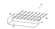
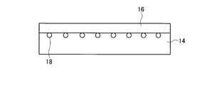
- the extruder die 12 has a discharge surface 14 having a plurality of discharge holes 18 through which the extruded resin composition discharges in the form of a strand, and a protrusion 16 projecting vertically from the discharge surface 14.
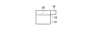
- the discharge holes 18 communicate with the flow passage 20 of molten resin as shown in FIG. 4, and the molten resin extruded from the extruder 10 passes through the flow passage 20 and is discharged from the discharge holes 18.
- the shape of the discharge hole 18 is circular in FIGS. 2 to 4, it may be a deformed circular shape such as an elliptical shape or an oval shape. However, the shape of the discharge hole 18 is set so that the cross-sectional shape of the strand to be discharged becomes a desired shape.
- the projecting portion 16 is formed such that its base portion is in contact with the upper outer periphery of each of the discharge holes 18 (see FIG. 3). More specifically, when the extruder die 12 is attached to the extruder, the base portion of the protrusion 16 is in contact with the upper portion of the discharge hole 18 in the vertical direction. That is, the outer peripheral upper portion of the discharge hole 18 is a portion located on the upper side of the outer periphery of the discharge hole 18 when the extruder die 12 is attached to the extruder. Then, since the root portion of the protrusion 16 is in contact with the outer peripheral upper portion of the discharge hole 18, there is no step with the protrusion 16 at the outer peripheral upper portion of the discharge hole 18 (see FIG. 4).
- the protrusion 16 does not interfere.
- the line of intersection between the discharge surface 14 and the projecting portion 16 is the discharge hole It is in contact with the top of the outer circumference of 18.
- the holes do not have a ring shape. This is because the protrusion 16 in contact with the upper portion of the outer periphery of the discharge hole 18 prevents the growth even if it is intended to grow in a ring shape. Then, in the portion other than the outer peripheral upper portion of the discharge hole 18, the grain grows.
- the mei- no becomes like a substantially U-shaped meani 44 which lacks the top as shown in FIG.
- the substantially U-shaped eyelet 44 Since the substantially U-shaped eyelet 44 is missing at the top and is not integrated, it is considered that the holding force against falling downward in the vertical direction is weaker than the ring-like eyelet without a missing portion over the entire circumference . Therefore, as the lower portion becomes heavier as the substantially U-shaped eyelet 44 grows, it will eventually drop downward in the vertical direction. Accordingly, adhesion of the strand to the strand and mixing into the final product (pellet) is reduced. Further, the ring-shaped entangled in the strand when it is separated from the discharge surface of the molding machine die, which causes the strand to be cut, but since the substantially U-shaped entrail 44 is easily dislocated downward, It is hard to get entangled and cutting of the strand is suppressed.
- the protrusion direction of the protrusion 16 from the discharge surface 14 should be provided parallel to the direction of the flow path 20 or inclined upward. Is preferred.
- the diameter of the discharge hole 18 is, for example, 2.0 to 7.0 mm. Further, the projection length of the projection 16 that protrudes from the discharge surface 14 is, for example, 5 to 20 mm.
- the material of the die for an extruder of the present embodiment is not particularly limited, and for example, metals such as stainless steel and cemented carbide can be used. Moreover, there is no restriction
- the discharge holes 18 are arranged in a straight line on the discharge surface 14, and the protrusions 16 are integrally formed in parallel with the arrangement direction of the discharge holes 18.
- the present embodiment is not limited to such a form.
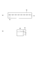
- a plurality of protrusions 16 A and 16 B may be formed for each discharge hole 18.
- the protrusion 16A in FIG. 6 is a rectangular protrusion in a front view, and similarly, the protrusion 16B in FIG. 7 is an arc protrusion.
- the root portions of the protrusions 16A and 16B are in contact with each other on the outer peripheral upper portion of the discharge hole 18. Therefore, even in the embodiment of FIGS. 6 and 7, the same effect as the embodiment shown in FIGS. 2 to 4 can be obtained.
- the protrusion part 16B is provided so that the outer side of a circular arc may become upward, it may be provided so that the outer side of a circular arc may face downward that is the reverse. Even if such a protrusion is provided, by providing the base portion in contact with the outer peripheral upper portion of the discharge hole 18, the same effect as the embodiment shown in FIG.
- the width (horizontal direction) of the protruding portion 16A shown in FIG. 6 be equal to or longer than the diameter of the discharge hole 18.
- the arc-shaped protruding portion 16B shown in FIG. 7 is a circular arc along the circumference of the discharge hole 18, the strand discharged from the discharge hole 18 is caught on the lower surface of the protruding portion 16B, and stable extrusion can not be performed. There is a tendency (see Comparative Example 2). Therefore, it is preferable that the radius of curvature of the arc of the protrusion 16B be larger than the radius of the discharge hole 18 so that the portion in contact with the outer periphery of the discharge hole 18 is reduced.
- one discharge hole may be sufficient. In that case, naturally, there is only one protrusion in contact with the discharge hole.
- the extruder of the present embodiment is characterized in that the extruder die of the present embodiment described above is mounted.
- the extruder according to the present embodiment is not particularly limited as long as it is an extruder having an extrusion screw, and examples thereof include a single-screw extruder, a different-direction twin-screw extruder, and a same-direction twin-screw extruder.
- the extruder die of this embodiment is mounted
- the method for producing a resin composition of the present embodiment is characterized in that at least a resin and an additive are charged into the extruder of the present embodiment and discharged from an extruder die to obtain a resin composition.
- a resin and an additive are charged into the extruder of the present embodiment and discharged from an extruder die to obtain a resin composition.
- a general purpose resin or an engineering resin may be sufficient.
- the additive to be used is not limited, and various stabilizers, various functional agents, various physical property enhancers and the like can be used.
- the manufacturing method of the present embodiment is particularly effective for manufacturing a resin composition which is likely to generate ring-shaped mei.
- a die for an extruder is charged with at least a polyacetal resin and a graft copolymer whose main chain is polyethylene and whose side chain is an acrylonitrile-styrene copolymer, in the extruder of the present embodiment described above.
- the polyacetal resin composition can be obtained by discharging from the above.
- the die of the extruder of the present embodiment described above can reduce the number of particles, and can suppress the mixing of particles into the final product and the breakage of strands. .
- Example 1 First, an extruder die shown in FIGS. 2 to 4 was prepared, which had a circular discharge hole with a diameter of 4.0 mm and a protrusion with a projection length of 10 mm from the discharge surface. . Next, the extruder die was mounted on a twin-screw extruder (TEX 65, manufactured by Japan Steel Works, Ltd.).
- TEX 65 twin-screw extruder
- a polyacetal resin (a polyacetal copolymer obtained by copolymerizing 96.7% by mass of trioxane and 3.3% by mass of 1,3-dioxolane (melt index (measured at 190 ° C., load 2160 g)): 2.5 g 10)) 100 parts by mass, 7 parts by mass of graft copolymer whose main chain is polyethylene and whose side chain is acrylonitrile-styrene copolymer, hindered phenolic antioxidant (product name: Irganox 1010, 0.5 parts by mass of BASF Japan Ltd.) was put into the above-mentioned twin-screw extruder, and extrusion was performed at a barrel set temperature: 200 ° C., screw rotation speed: 280 rpm, extrusion amount: 350 kg / h. Further, as shown in FIG. 1, the extruded strand was conveyed to the cutter 32 through the water bath 30.
- Comparative Example 1 The resin composition was extruded in the same manner as in Example 1 except that an extruder die having no protrusion was used. And it evaluated similarly to Example 1. The evaluation results are shown in Table 1.
- Comparative Example 2 The resin composition was extruded in the same manner as in Example 1 except that the extruder die shown in FIG. 8 was used as the extruder die. And it evaluated similarly to Example 1. The evaluation results are shown in Table 1.
- the root portion of the protrusion 16 is not in contact with the discharge hole 18 as shown in FIGS. 2 to 3, and the root portion of the protrusion 16 is located above the discharge hole 18. It is extended to a part, and a part of the protrusion 16 is hollowed out so as to match the outer periphery of the discharge hole 18. Further, in the present comparative example, the strand expanded immediately after the discharge from the discharge hole 18 was caught in the hollow portion of the protrusion 16, and stable extrusion could not be performed.
- Comparative Example 3 The extrusion was performed in the same manner as in Example 1 except that a die for an extruder provided so that the root portion of the protrusion was in contact with the lowermost portion of the outer periphery of the discharge hole was used. And it evaluated similarly to Example 1. The evaluation results are shown in Table 1. In the present comparative example, a situation occurred in which the strand was caught on the lower protruding portion and cut.
- Example 1 From Table 1, it can be seen that in Example 1, the growth of meiander was suppressed and there was no strand breakage. In particular, it was a very excellent result that strand breakage did not occur even after 60 hours of operation. On the other hand, in Comparative Example 1, the occurrence of growth, growth and separation from the discharge surface were repeated, and the strand was cut at a level of about twice per hour, which is a practical problem. In Comparative Examples 2 and 3, the strand was caught on the protrusion of the extruder die, and continuous extrusion was not possible.
Landscapes
- Engineering & Computer Science (AREA)
- Mechanical Engineering (AREA)
- Manufacturing & Machinery (AREA)
- Extrusion Moulding Of Plastics Or The Like (AREA)
- Processing And Handling Of Plastics And Other Materials For Molding In General (AREA)
Abstract
溶融樹脂がストランドの形態で吐出する1又は複数の吐出孔を有する吐出面と、吐出面から垂直方向に突出する1又は複数の突出部と、を備え、突出部の根本部分の一部が、各吐出孔の外周上部に接している押出機用ダイ、及び該押出機用ダイが装着されている押出機、並びに少なくとも樹脂及び添加剤を該押出機に投入して、押出機用ダイから吐出させて樹脂組成物を得る樹脂組成物の製造方法である。
Description
本発明は、樹脂組成物の押出成形に用いられる押出機用ダイ、押出機、押出機を用いた樹脂組成物の製造方法に関する。
押出機を用いて樹脂組成物をストランド状に押し出す際、樹脂組成物によっては、その一部の成分が押出機用ダイの吐出孔の周囲に付着することがある。このような付着物は、メヤニ(gum)と呼ばれることがあり種々の悪影響を及ぼす。例えば、吐出孔の周囲にメヤニが付着した状態で樹脂組成物の押し出しを続けると、メヤニがリング状に成長してストランドに絡まりつくことがある。そのようなメヤニを放置すると製品に混入することがあり、製品へのメヤニの混入により品質低下が危惧される。あるいは、リング状に成長したメヤニが押出機用ダイから離脱する際にストランドが切断されることがある。これは1時間当たり数回の高頻度で発生するため、常に監視し、必要に応じて成形を中断してメヤニを除去したり、押出機用ダイのメンテナンスをしたりする必要がある。
そのため、押出機用ダイにおけるメヤニの発生又は成長を抑えるため、従来、種々の検討がなされている(例えば、特許文献1、2)。特許文献1、2には、樹脂が押し出される吐出孔の付近に気体を吹き付けてメヤニを吹き飛ばすための機構を有する押出機用ダイが開示されている。
特許文献1、2に開示されている押出機用ダイは、いずれも気体供給源及び樹脂の吐出口に気体を吹き付ける機構が別途必要となる。そのため、やや複雑な機構を要し、その分、押出機用ダイの製造コストや維持コストの増大の原因となる。
本発明は、上記従来の問題点に鑑みなされたものである。そして、その目的は、簡単な構造により吐出孔付近の付着物(メヤニ)の成長を抑制しうる押出機用ダイ、その押出機用ダイを用いた押出機、及びその押出機を用いた樹脂組成物の製造方法を提供することにある。
本発明者は、鋭意検討した結果、押出機を用いた樹脂組成物の押し出しに際し、押出機用ダイの吐出孔周囲にメヤニが成長してストランドに絡まりついたり、ストランドの切断の原因となったりするのは、メヤニの形状がリング状であることに起因すること見出し本発明を完成するに至った。すなわち、前記課題を解決する本発明は以下の通りである。
本発明の押出機用ダイは、溶融樹脂がストランドの形態で吐出する1又は複数の吐出孔を有する吐出面と、吐出面から垂直方向に突出する1又は複数の突出部と、を備え、突出部の根本部分の一部が、各吐出孔の外周上部に接している押出機用ダイである。
本発明の押出機用ダイにおいては、吐出孔の上部に突出部の根本部分の一部が接しているため、メヤニは上部が欠落した形状、すなわち略U字状となり、リング状に成長することはない。そのため鉛直方向下方に脱落しやすくなり、メヤニがストランドに絡まりついたり、ストランドが切断されたりするといった問題を低減することができる。
本発明の押出機用ダイにおいては、吐出孔の上部に突出部の根本部分の一部が接しているため、メヤニは上部が欠落した形状、すなわち略U字状となり、リング状に成長することはない。そのため鉛直方向下方に脱落しやすくなり、メヤニがストランドに絡まりついたり、ストランドが切断されたりするといった問題を低減することができる。
本発明の押出機用ダイにおいては、吐出面の吐出孔は複数であって、該複数の吐出孔が吐出面において一直線上に配列し、突出部が吐出孔の配列方向と平行に一体に形成されている構成とすることが好ましい。
本発明の押出機は、上記本発明の押出機用ダイが装着されている押出機である。すなわち、本発明の押出機により樹脂組成物を押し出すに際し、メヤニがストランドに絡まりついたり、ストランドが切断されたりする上記問題点を解消することができる。
本発明の樹脂組成物の製造方法は、少なくとも樹脂及び添加剤を、本発明の押出機に投入して、押出機用ダイから吐出させて樹脂組成物を得る樹脂組成物の製造方法である。
本発明の樹脂組成物の製造方法は、前記本発明の押出機を用いるため、樹脂組成物を押し出しする際に本来なら押出機用ダイの吐出孔の周囲にメヤニが発生するような樹脂組成物であっても、メヤニの成長を抑制できるため有用である。例えば、樹脂がポリアセタール樹脂であり、添加剤が、主鎖がポリエチレンであり、側鎖がアクリロニトリル-スチレン共重合体であるグラフト共重合体である樹脂組成物の場合、メヤニが発生することがあり、そのような樹脂組成物の押し出しに際しメヤニに起因する問題を解消することができる。
本発明の樹脂組成物の製造方法は、前記本発明の押出機を用いるため、樹脂組成物を押し出しする際に本来なら押出機用ダイの吐出孔の周囲にメヤニが発生するような樹脂組成物であっても、メヤニの成長を抑制できるため有用である。例えば、樹脂がポリアセタール樹脂であり、添加剤が、主鎖がポリエチレンであり、側鎖がアクリロニトリル-スチレン共重合体であるグラフト共重合体である樹脂組成物の場合、メヤニが発生することがあり、そのような樹脂組成物の押し出しに際しメヤニに起因する問題を解消することができる。
本発明によれば、簡単な構造により吐出孔付近の付着物の成長を抑制しうる押出機用ダイ、その押出機用ダイを用いた押出機、及びその押出機を用いた樹脂組成物の製造方法を提供することができる。
<押出機用ダイ>
本実施形態の押出機用ダイは、溶融樹脂がストランドの形態で吐出する1又は複数の吐出孔を有する吐出面と、吐出面から垂直方向に突出する1又は複数の突出部と、を備え、突出部の根本部分の一部が、各吐出孔の外周上部に接していることを特徴としている。吐出孔の外周上部とは、吐出孔の外周の最も上側に位置する部位のみならず、その近傍をも含む。すなわち、後述するように、メヤニが略U字状となり、かつ、成長したメヤニが脱落するのであれば、必ずしも突出部は吐出孔の外周の最上部に形成される必要はない。より具体的には、最上部を12時の位置としたとき、突出部と吐出孔が接する位置は11~13時の範囲の位置とすることができる。
本実施形態の押出機用ダイは、溶融樹脂がストランドの形態で吐出する1又は複数の吐出孔を有する吐出面と、吐出面から垂直方向に突出する1又は複数の突出部と、を備え、突出部の根本部分の一部が、各吐出孔の外周上部に接していることを特徴としている。吐出孔の外周上部とは、吐出孔の外周の最も上側に位置する部位のみならず、その近傍をも含む。すなわち、後述するように、メヤニが略U字状となり、かつ、成長したメヤニが脱落するのであれば、必ずしも突出部は吐出孔の外周の最上部に形成される必要はない。より具体的には、最上部を12時の位置としたとき、突出部と吐出孔が接する位置は11~13時の範囲の位置とすることができる。
以下にまず、本実施形態の押出機用ダイが使用される押出機及びその周辺の機器の一例について説明する。図1は、押出機10により押し出され、押出機用ダイ12から吐出した樹脂組成物からなるストランド40が、冷却用の水が収容されたウォーターバス30を経てカッター32によりカッティングされてペレット42が作製される様子を概念的に示している。つまり、ストランド40は、押出機10から押し出された後、ウォーターバス30に投入されて冷却され、その後、カッター32に搬送され所定の長さにカッティングされてペレット42となる。本実施形態の押出機用ダイ12は、図1に示すような押出成形のプロセスに用いられる押出機10の樹脂の吐出口に装着されるものである。
図2~図4は、本実施形態の押出機用ダイ12の一例を示している。押出機用ダイ12は、押し出された樹脂組成物がストランドの形態で吐出する複数の吐出孔18を有する吐出面14と、吐出面14から垂直方向に突出する突出部16とを有する。吐出孔18は、図4に示すように溶融樹脂の流路20に連通しており、押出機10から押し出された溶融樹脂は流路20を通過して吐出孔18から吐出する。また、図2~図4においては吐出孔18の形状は円形としているが、楕円形、長円形など、変形した円形であってもよい。もっとも、吐出孔18の形状は、吐出するストランドの断面形状が所望の形状となるように設定される。
突出部16は、その根本部分が吐出孔18それぞれの外周上部に接するように形成されている(図3参照)。より具体的には、押出機用ダイ12が押出機に装着されたとき、吐出孔18の鉛直方向における上部において突出部16の根本部分が接している。つまり、吐出孔18の外周上部とは、押出機用ダイ12が押出機に装着された場合において、吐出孔18の外周の上側に位置する部位である。そして、突出部16の根本部分が吐出孔18の外周上部に接しているのであるから、吐出孔18の外周上部において突出部16との段差は生じていない(図4参照)。つまり、流路20を流れる溶融樹脂が吐出孔18から吐出する際、突出部16は干渉しない。
なお、本実施形態においては、突出部16の根本部分の一部が、各吐出孔18の外周上部に接しているのであるが、換言すると、吐出面14及び突出部16の交線が吐出孔18の外周上部に接している。
なお、本実施形態においては、突出部16の根本部分の一部が、各吐出孔18の外周上部に接しているのであるが、換言すると、吐出面14及び突出部16の交線が吐出孔18の外周上部に接している。
本実施形態の押出機用ダイ12を用い、樹脂組成物を吐出孔18から吐出する際において、吐出孔18の周囲にメヤニが生ずる場合であっても、そのメヤニはリング状とはならない。これは、メヤニがリング状に成長しようとしても、吐出孔18の外周上部に接する突出部16がその成長を阻むからである。そして、吐出孔18の外周上部以外の部分においてはメヤニが成長する。そのメヤニは、図5に示すように上部が欠落した略U字状のメヤニ44のようになる。略U字状のメヤニ44は上部で欠落しており、一体となっていないため、全周にわたり欠落した部分がないリング状のメヤニよりも鉛直方向下方への脱落に対する保持力が弱いと考えられる。そのため、略U字状のメヤニ44は成長とともに下側部分が重くなるにつれてやがて鉛直方向下方に脱落することとなる。従って、ストランドにメヤニが付着して最終製品(ペレット)に混入することが低減される。また、リング状のメヤニは成形機用ダイの吐出面から離脱する際にストランドに絡まり、ストランドが切断される原因となるが、略U字状のメヤニ44は下方に脱落しやすいため、ストランドに絡まりにくくストランドの切断が抑えられる。
吐出孔18から吐出した樹脂が突出部16の下面と緩衝しないようにするため、突出部16の吐出面14からの突出方向は流路20の方向と平行、又は上側に傾斜するように設けることが好ましい。
吐出孔18の直径は、例えば2.0~7.0mmである。また、突出部16の吐出面14から突出する突出長さは、例えば5~20mmである。
本実施形態の押出機用ダイの材料としては、特に制限はないが、例えば、ステンレス、超硬合金などの金属を用いることができる。また、本実施形態の押出機用ダイの製法としては、突出部を形成することを除き特に制限はなく、公知の押出機用ダイと同様に製造することができる。
次いで、本実施形態の押出機用ダイの変形例を2例示す。図2~図4に示す形態では、吐出孔18は吐出面14において一直線上に配列し、突出部16が吐出孔18の配列方向と平行に一体に形成されている形態を示した。本実施形態はそのような形態に限定されることはなく、例えば、図6、図7に示すように、それぞれの吐出孔18に対して突出部16A、16Bを複数形成してもよい。図6における突出部16Aは、正面視で矩形状の突出部であり、同様に図7における突出部16Bは円弧状の突出部である。いずれの形態においても吐出孔18の外周上部において突出部16A、16Bの根本部分が接した状態となっている。従って、図6及び図7の形態においても、図2~図4に示す形態と同様の効果を奏する。なお、図7においては、突出部16Bは、円弧の外側が上向きとなるように設けられているが、その逆、すなわち、円弧の外側が下向きとなるように設けられてもよい。そのような突出部であっても、その根本部分が吐出孔18の外周上部と接するように設けることにより図7に示す形態と同等の効果を奏する。
図6に示す突出部16Aの幅(水平方向)は、吐出孔18の直径以上の長さとすることが好ましい。このように設定すると、略U字状のメヤニの上部において欠落した部分が増し、略U字状のメヤニが脱落しやすくなるためである。
また、図7に示す円弧状の突出部16Bは、吐出孔18の円周に沿った円弧であると、吐出孔18から吐出するストランドが突出部16Bの下面に引っかかり、安定した押し出しができなくなる傾向にある(比較例2参照)。そこで、突出部16Bの円弧の曲率半径は、吐出孔18の半径よりも大きくし、吐出孔18の外周と接する部分が少なくなるようにすることが好ましい。
また、図7に示す円弧状の突出部16Bは、吐出孔18の円周に沿った円弧であると、吐出孔18から吐出するストランドが突出部16Bの下面に引っかかり、安定した押し出しができなくなる傾向にある(比較例2参照)。そこで、突出部16Bの円弧の曲率半径は、吐出孔18の半径よりも大きくし、吐出孔18の外周と接する部分が少なくなるようにすることが好ましい。
以上は、吐出面に複数の吐出孔を有する形態を示したが、吐出孔は1つであってもよい。その場合、その吐出孔に接する突出部も当然に1つである。
<押出機>
本実施形態の押出機は、以上の本実施形態の押出機用ダイが装着されていることを特徴としている。本実施形態の押出機としては押出スクリューを有する押出機であれば特に限定はなく、単軸押出機、異方向二軸押出機、同方向二軸押出機等を挙げることができる。そして、本実施形態の押出機は、上述の本実施形態の押出機用ダイが装着されるため、当該押出機用ダイの吐出孔付近のメヤニの成長を抑制することができる。そのため、押し出しの際にメヤニがストランドから脱落しやすくなり、ひいてはメヤニが最終製品に混入することや、メヤニに起因するストランドの切断を低減することができる。
本実施形態の押出機は、以上の本実施形態の押出機用ダイが装着されていることを特徴としている。本実施形態の押出機としては押出スクリューを有する押出機であれば特に限定はなく、単軸押出機、異方向二軸押出機、同方向二軸押出機等を挙げることができる。そして、本実施形態の押出機は、上述の本実施形態の押出機用ダイが装着されるため、当該押出機用ダイの吐出孔付近のメヤニの成長を抑制することができる。そのため、押し出しの際にメヤニがストランドから脱落しやすくなり、ひいてはメヤニが最終製品に混入することや、メヤニに起因するストランドの切断を低減することができる。
<樹脂組成物の製造方法>
本実施形態の樹脂組成物の製造方法は、少なくとも樹脂及び添加剤を、前記本実施形態の押出機に投入して、押出機用ダイから吐出させて樹脂組成物を得ることを特徴としている。本実施形態の樹脂組成物の製造方法において使用される樹脂には特に制限はなく、汎用樹脂でも、エンジニアリング樹脂でもよい。また、使用される添加剤においても制限はなく、各種安定剤、各種機能付与剤、各種物性強化剤等の使用が可能である。本実施形態の製造方法は、特にリング状メヤニを発生しやすい樹脂組成物の製造に有効である。
本実施形態の樹脂組成物の製造方法は、少なくとも樹脂及び添加剤を、前記本実施形態の押出機に投入して、押出機用ダイから吐出させて樹脂組成物を得ることを特徴としている。本実施形態の樹脂組成物の製造方法において使用される樹脂には特に制限はなく、汎用樹脂でも、エンジニアリング樹脂でもよい。また、使用される添加剤においても制限はなく、各種安定剤、各種機能付与剤、各種物性強化剤等の使用が可能である。本実施形態の製造方法は、特にリング状メヤニを発生しやすい樹脂組成物の製造に有効である。
例えば、少なくとも、ポリアセタール樹脂と、主鎖がポリエチレンであり、側鎖がアクリロニトリル-スチレン共重合体であるグラフト共重合体とを、上述の本実施形態の押出機に投入して、押出機用ダイから吐出させてポリアセタール樹脂組成物を得ることができる。このような樹脂組成物を得る際に押出機により押し出しをすると、当該グラフト共重合体を由来とするメヤニが押出機用ダイの吐出孔の周囲に発生しやすい傾向にある。そこで、本実施形態の押出機を用いて押し出しをすると、上述の本実施形態の押出機用ダイにより、メヤニが低減され、最終製品へのメヤニの混入や、ストランドの切断を抑制することができる。
以下、実施例により本発明を更に詳しく説明するが、本発明はこれらに限定されるものではない。
[実施例1]
まず、図2~図4に示す形態の押出機用ダイであって、直径4.0mmの円形の吐出孔を有し、吐出面からの突出長さが10mmの突出部を有するものを準備した。次いで、この押出機用ダイを、二軸押出機(日本製鋼所製TEX65)に装着した。
次に、ポリアセタール樹脂(トリオキサン96.7質量%と1,3-ジオキソラン3.3質量%とを共重合させてなるポリアセタール共重合体(メルトインデックス(190℃,荷重2160gで測定):2.5g/10min))100質量部と、主鎖がポリエチレンであり、側鎖がアクリロニトリル-スチレン共重合体であるグラフト共重合体7質量部と、ヒンダードフェノール系酸化防止剤(製品名:Irganox 1010,BASFジャパン社製)0.5質量部とを、上記二軸押出機に投入し、バレル設定温度:200℃、スクリュー回転数:280rpm、押出量:350kg/hにて押し出しを行った。また、押し出されたストランドは、図1に示すように、ウォーターバス30を経てカッター32に搬送されるようにした。
まず、図2~図4に示す形態の押出機用ダイであって、直径4.0mmの円形の吐出孔を有し、吐出面からの突出長さが10mmの突出部を有するものを準備した。次いで、この押出機用ダイを、二軸押出機(日本製鋼所製TEX65)に装着した。
次に、ポリアセタール樹脂(トリオキサン96.7質量%と1,3-ジオキソラン3.3質量%とを共重合させてなるポリアセタール共重合体(メルトインデックス(190℃,荷重2160gで測定):2.5g/10min))100質量部と、主鎖がポリエチレンであり、側鎖がアクリロニトリル-スチレン共重合体であるグラフト共重合体7質量部と、ヒンダードフェノール系酸化防止剤(製品名:Irganox 1010,BASFジャパン社製)0.5質量部とを、上記二軸押出機に投入し、バレル設定温度:200℃、スクリュー回転数:280rpm、押出量:350kg/hにて押し出しを行った。また、押し出されたストランドは、図1に示すように、ウォーターバス30を経てカッター32に搬送されるようにした。
[評価]
1.メヤニの成長
樹脂組成物の押し出し開始から、押出機用ダイの吐出孔付近においてメヤニの成長を目視評価した。メヤニが成長途中で吐出孔付近から脱落した場合を○、メヤニが吐出孔付近を離脱してストランドに絡まった場合を×として評価した。評価結果を表1に示す。
1.メヤニの成長
樹脂組成物の押し出し開始から、押出機用ダイの吐出孔付近においてメヤニの成長を目視評価した。メヤニが成長途中で吐出孔付近から脱落した場合を○、メヤニが吐出孔付近を離脱してストランドに絡まった場合を×として評価した。評価結果を表1に示す。
2.ストランドの切断
樹脂組成物の押し出し処理を60時間続行し、ストランドが切断される回数を計数した。また、1時間当たりのストランドの切断回数を算出した。それらの結果を表1に示す。
樹脂組成物の押し出し処理を60時間続行し、ストランドが切断される回数を計数した。また、1時間当たりのストランドの切断回数を算出した。それらの結果を表1に示す。
[比較例1]
突出部のない押出機用ダイを用いたこと以外は、実施例1と同様にして樹脂組成物の押し出しを行った。そして、実施例1と同様に評価した。評価結果を表1に示す。
突出部のない押出機用ダイを用いたこと以外は、実施例1と同様にして樹脂組成物の押し出しを行った。そして、実施例1と同様に評価した。評価結果を表1に示す。
[比較例2]
押出機用ダイとして、図8に示す押出機用ダイを用いたこと以外は実施例1と同様にして樹脂組成物の押し出しを行った。そして、実施例1と同様に評価した。評価結果を表1に示す。なお、図8に示す押出機用ダイは、図2~図3に示すように突出部16の根本部分が吐出孔18に接するのではなく、突出部16の根本部分を吐出孔18の上部にまで延在させ、突出部16の一部を吐出孔18の外周と一致するようにくり抜いたものである。また、本比較例においては、吐出孔18から吐出直後に膨張したストランドが突出部16のくり抜き部分に引っかかり、安定した押し出しができなかった。
押出機用ダイとして、図8に示す押出機用ダイを用いたこと以外は実施例1と同様にして樹脂組成物の押し出しを行った。そして、実施例1と同様に評価した。評価結果を表1に示す。なお、図8に示す押出機用ダイは、図2~図3に示すように突出部16の根本部分が吐出孔18に接するのではなく、突出部16の根本部分を吐出孔18の上部にまで延在させ、突出部16の一部を吐出孔18の外周と一致するようにくり抜いたものである。また、本比較例においては、吐出孔18から吐出直後に膨張したストランドが突出部16のくり抜き部分に引っかかり、安定した押し出しができなかった。
[比較例3]
突出部の根本部分が吐出孔の外周最下部に接するように設けた押出機用ダイを用いたこと以外は実施例1と同様にして押し出しを行った。そして、実施例1と同様に評価した。評価結果を表1に示す。なお、本比較例においては、ストランドが下部に設けられた突出部に引っかかり、切断されるという事態が発生した。
突出部の根本部分が吐出孔の外周最下部に接するように設けた押出機用ダイを用いたこと以外は実施例1と同様にして押し出しを行った。そして、実施例1と同様に評価した。評価結果を表1に示す。なお、本比較例においては、ストランドが下部に設けられた突出部に引っかかり、切断されるという事態が発生した。

表1より、実施例1においては、メヤニの成長が抑制され、ストランドの切断がなかったことが分かる。特に、60時間稼働してもストランドの切断が生じなかったという、非常に優れた結果であった。これに対して、比較例1においては、メヤニの発生、成長、吐出面からの離脱を繰り返し、ストランドの切断は毎時約2回発生という実用上問題となるレベルであった。比較例2及び3においては、ストランドが押出機用ダイの突出部に引っかかり、継続的な押し出しは不可能であった。
10 押出機
12 押出機用ダイ
14 吐出面
16 突出部
18 吐出孔
20 流路
12 押出機用ダイ
14 吐出面
16 突出部
18 吐出孔
20 流路
Claims (5)
- 溶融樹脂がストランドの形態で吐出する1又は複数の吐出孔を有する吐出面と、
前記吐出面から垂直方向に突出する1又は複数の突出部と、を備え、
前記突出部の根本部分の一部が、前記各吐出孔の外周上部に接している押出機用ダイ。 - 前記吐出面の吐出孔は複数であって、該複数の吐出孔が前記吐出面において一直線上に配列し、前記突出部が前記吐出孔の配列方向と平行に一体に形成されている請求項1に記載の押出機用ダイ。
- 請求項1又は2に記載の押出機用ダイが装着されている押出機。
- 少なくとも樹脂及び添加剤を請求項3に記載の押出機に投入して、前記押出機用ダイから吐出させて樹脂組成物を得る樹脂組成物の製造方法。
- 前記樹脂が、ポリアセタール樹脂であり、前記添加剤が、主鎖がポリエチレンであり、側鎖がアクリロニトリル-スチレン共重合体であるグラフト共重合体である、請求項4に記載の樹脂組成物の製造方法。
Priority Applications (2)
| Application Number | Priority Date | Filing Date | Title |
|---|---|---|---|
| CN201880062196.3A CN111132810B (zh) | 2017-09-28 | 2018-09-19 | 挤出机用模具、挤出机以及树脂组合物的制造方法 |
| MYPI2020001549A MY194526A (en) | 2017-09-28 | 2018-09-19 | Extruder die, extruder, and method of manufacturing resin composition |
Applications Claiming Priority (2)
| Application Number | Priority Date | Filing Date | Title |
|---|---|---|---|
| JP2017188391A JP6943711B2 (ja) | 2017-09-28 | 2017-09-28 | 押出機用ダイ、押出機、及び樹脂組成物の製造方法 |
| JP2017-188391 | 2017-09-28 |
Publications (1)
| Publication Number | Publication Date |
|---|---|
| WO2019065403A1 true WO2019065403A1 (ja) | 2019-04-04 |
Family
ID=65903453
Family Applications (1)
| Application Number | Title | Priority Date | Filing Date |
|---|---|---|---|
| PCT/JP2018/034637 Ceased WO2019065403A1 (ja) | 2017-09-28 | 2018-09-19 | 押出機用ダイ、押出機、及び樹脂組成物の製造方法 |
Country Status (4)
| Country | Link |
|---|---|
| JP (1) | JP6943711B2 (ja) |
| CN (1) | CN111132810B (ja) |
| MY (1) | MY194526A (ja) |
| WO (1) | WO2019065403A1 (ja) |
Citations (3)
| Publication number | Priority date | Publication date | Assignee | Title |
|---|---|---|---|---|
| JPS5690317U (ja) * | 1979-12-14 | 1981-07-18 | ||
| JPH03101903A (ja) * | 1989-09-14 | 1991-04-26 | Polyplastics Co | 熱可塑性樹脂組成物の製造方法 |
| JP2011056762A (ja) * | 2009-09-09 | 2011-03-24 | Hitachi Cable Ltd | 樹脂組成物の押出装置及び樹脂組成物の製造方法 |
Family Cites Families (4)
| Publication number | Priority date | Publication date | Assignee | Title |
|---|---|---|---|---|
| JPS63242514A (ja) * | 1987-03-30 | 1988-10-07 | Tatsuta Electric Wire & Cable Co Ltd | 断面u型、c型長尺物の押出成形方法 |
| JP2012171160A (ja) * | 2011-02-21 | 2012-09-10 | Canon Inc | 粉体粒子の熱処理装置及び粉体粒子の製造方法 |
| JP5728077B2 (ja) * | 2011-03-31 | 2015-06-03 | ポリプラスチックス株式会社 | 熱可塑性樹脂組成物ペレットの製造方法、押出機及びダイプレート |
| CN203697434U (zh) * | 2014-01-20 | 2014-07-09 | 江苏苏中电缆厂有限公司 | 一种避免线缆损伤的电线电缆押出机机头 |
-
2017
- 2017-09-28 JP JP2017188391A patent/JP6943711B2/ja active Active
-
2018
- 2018-09-19 MY MYPI2020001549A patent/MY194526A/en unknown
- 2018-09-19 WO PCT/JP2018/034637 patent/WO2019065403A1/ja not_active Ceased
- 2018-09-19 CN CN201880062196.3A patent/CN111132810B/zh active Active
Patent Citations (3)
| Publication number | Priority date | Publication date | Assignee | Title |
|---|---|---|---|---|
| JPS5690317U (ja) * | 1979-12-14 | 1981-07-18 | ||
| JPH03101903A (ja) * | 1989-09-14 | 1991-04-26 | Polyplastics Co | 熱可塑性樹脂組成物の製造方法 |
| JP2011056762A (ja) * | 2009-09-09 | 2011-03-24 | Hitachi Cable Ltd | 樹脂組成物の押出装置及び樹脂組成物の製造方法 |
Also Published As
| Publication number | Publication date |
|---|---|
| MY194526A (en) | 2022-11-30 |
| JP6943711B2 (ja) | 2021-10-06 |
| CN111132810A (zh) | 2020-05-08 |
| CN111132810B (zh) | 2022-04-15 |
| JP2019064004A (ja) | 2019-04-25 |
Similar Documents
| Publication | Publication Date | Title |
|---|---|---|
| JP6340430B2 (ja) | ファスナーエレメント及びファスナーエレメントの製造方法 | |
| KR100975303B1 (ko) | 스트링잉 방지 부재 및 사출성형기 | |
| WO2019065403A1 (ja) | 押出機用ダイ、押出機、及び樹脂組成物の製造方法 | |
| JP2017159601A (ja) | ペレタイザ、及び、これを用いたペレットの製造方法 | |
| CN100430195C (zh) | 树脂挤压机模具装置及挤压方法 | |
| CN102414008A (zh) | 包括凸形布置的喷嘴的喷嘴板及其应用 | |
| JP2019147395A (ja) | ペレタイザ、及び、これを用いたペレットの製造方法 | |
| JP3681172B2 (ja) | 樹脂組成物の押出方法及び装置 | |
| JP2012040789A (ja) | 押出機用ストランドダイスおよび樹脂ペレットの製造方法 | |
| JP2009184303A (ja) | 二軸スクリュ押出機における脱揮成分の分離方法及び装置 | |
| CN104105560B (zh) | 可枢转浇口盘和用于连续浇铸金属合金的方法,可枢转浇口盘和金属合金的细长浇铸条的用途 | |
| JP4321329B2 (ja) | 樹脂成形用ダイ及び樹脂成形品の製造方法 | |
| TWI564136B (zh) | Thermoplastic resin composition, a method for producing a compressed product, an extruder, and a mold plate | |
| JP3717485B2 (ja) | 樹脂ペレット製造用ダイ及び該ダイを用いた樹脂ペレットの製造方法 | |
| JPH07125046A (ja) | 合成樹脂管の製造方法 | |
| JPH05220811A (ja) | 成形用樹脂組成物製造用口金 | |
| JP5141021B2 (ja) | プリフォーム圧縮成形装置およびプリフォーム圧縮成形方法 | |
| JP7544769B2 (ja) | 押出機用ダイプレート | |
| JP3147026U (ja) | 引取りロール | |
| JPH11254430A (ja) | 成形用樹脂材の製造方法及び装置 | |
| JP4739005B2 (ja) | ダイスおよびフィルムの製造方法 | |
| JP2013169758A (ja) | ブレーカープレート | |
| JP2010017947A (ja) | 熱可塑性樹脂の押出用シングルスクリューとそのスクリューを用いた押出成形方法 | |
| JPH09239803A (ja) | 成形用樹脂組成物製造用口金 | |
| JP2018076619A (ja) | ポリフッ化ビニリデン系モノフィラメント及びポリフッ化ビニリデン系モノフィラメントの製造方法 |
Legal Events
| Date | Code | Title | Description |
|---|---|---|---|
| NENP | Non-entry into the national phase |
Ref country code: DE |
|
| 122 | Ep: pct application non-entry in european phase |
Ref document number: 18862109 Country of ref document: EP Kind code of ref document: A1 |