WO2019065183A1 - 車両用可変容量型圧縮機 - Google Patents
車両用可変容量型圧縮機 Download PDFInfo
- Publication number
- WO2019065183A1 WO2019065183A1 PCT/JP2018/033447 JP2018033447W WO2019065183A1 WO 2019065183 A1 WO2019065183 A1 WO 2019065183A1 JP 2018033447 W JP2018033447 W JP 2018033447W WO 2019065183 A1 WO2019065183 A1 WO 2019065183A1
- Authority
- WO
- WIPO (PCT)
- Prior art keywords
- connector
- vehicle
- electromagnetic
- electromagnetic coil
- power supply
- Prior art date
- Legal status (The legal status is an assumption and is not a legal conclusion. Google has not performed a legal analysis and makes no representation as to the accuracy of the status listed.)
- Ceased
Links
Images




Classifications
-
- F—MECHANICAL ENGINEERING; LIGHTING; HEATING; WEAPONS; BLASTING
- F04—POSITIVE - DISPLACEMENT MACHINES FOR LIQUIDS; PUMPS FOR LIQUIDS OR ELASTIC FLUIDS
- F04B—POSITIVE-DISPLACEMENT MACHINES FOR LIQUIDS; PUMPS
- F04B27/00—Multi-cylinder pumps specially adapted for elastic fluids and characterised by number or arrangement of cylinders
- F04B27/08—Multi-cylinder pumps specially adapted for elastic fluids and characterised by number or arrangement of cylinders having cylinders coaxial with, or parallel or inclined to, main shaft axis
- F04B27/14—Control
-
- F—MECHANICAL ENGINEERING; LIGHTING; HEATING; WEAPONS; BLASTING
- F04—POSITIVE - DISPLACEMENT MACHINES FOR LIQUIDS; PUMPS FOR LIQUIDS OR ELASTIC FLUIDS
- F04B—POSITIVE-DISPLACEMENT MACHINES FOR LIQUIDS; PUMPS
- F04B27/00—Multi-cylinder pumps specially adapted for elastic fluids and characterised by number or arrangement of cylinders
- F04B27/08—Multi-cylinder pumps specially adapted for elastic fluids and characterised by number or arrangement of cylinders having cylinders coaxial with, or parallel or inclined to, main shaft axis
- F04B27/14—Control
- F04B27/16—Control of pumps with stationary cylinders
- F04B27/18—Control of pumps with stationary cylinders by varying the relative positions of a swash plate and a cylinder block
- F04B27/1804—Controlled by crankcase pressure
-
- F—MECHANICAL ENGINEERING; LIGHTING; HEATING; WEAPONS; BLASTING
- F04—POSITIVE - DISPLACEMENT MACHINES FOR LIQUIDS; PUMPS FOR LIQUIDS OR ELASTIC FLUIDS
- F04B—POSITIVE-DISPLACEMENT MACHINES FOR LIQUIDS; PUMPS
- F04B27/00—Multi-cylinder pumps specially adapted for elastic fluids and characterised by number or arrangement of cylinders
- F04B27/08—Multi-cylinder pumps specially adapted for elastic fluids and characterised by number or arrangement of cylinders having cylinders coaxial with, or parallel or inclined to, main shaft axis
- F04B27/10—Multi-cylinder pumps specially adapted for elastic fluids and characterised by number or arrangement of cylinders having cylinders coaxial with, or parallel or inclined to, main shaft axis having stationary cylinders
-
- F—MECHANICAL ENGINEERING; LIGHTING; HEATING; WEAPONS; BLASTING
- F04—POSITIVE - DISPLACEMENT MACHINES FOR LIQUIDS; PUMPS FOR LIQUIDS OR ELASTIC FLUIDS
- F04B—POSITIVE-DISPLACEMENT MACHINES FOR LIQUIDS; PUMPS
- F04B27/00—Multi-cylinder pumps specially adapted for elastic fluids and characterised by number or arrangement of cylinders
- F04B27/08—Multi-cylinder pumps specially adapted for elastic fluids and characterised by number or arrangement of cylinders having cylinders coaxial with, or parallel or inclined to, main shaft axis
- F04B27/10—Multi-cylinder pumps specially adapted for elastic fluids and characterised by number or arrangement of cylinders having cylinders coaxial with, or parallel or inclined to, main shaft axis having stationary cylinders
- F04B27/1009—Distribution members
-
- F—MECHANICAL ENGINEERING; LIGHTING; HEATING; WEAPONS; BLASTING
- F04—POSITIVE - DISPLACEMENT MACHINES FOR LIQUIDS; PUMPS FOR LIQUIDS OR ELASTIC FLUIDS
- F04B—POSITIVE-DISPLACEMENT MACHINES FOR LIQUIDS; PUMPS
- F04B27/00—Multi-cylinder pumps specially adapted for elastic fluids and characterised by number or arrangement of cylinders
- F04B27/08—Multi-cylinder pumps specially adapted for elastic fluids and characterised by number or arrangement of cylinders having cylinders coaxial with, or parallel or inclined to, main shaft axis
- F04B27/10—Multi-cylinder pumps specially adapted for elastic fluids and characterised by number or arrangement of cylinders having cylinders coaxial with, or parallel or inclined to, main shaft axis having stationary cylinders
- F04B27/1036—Component parts, details, e.g. sealings, lubrication
-
- F—MECHANICAL ENGINEERING; LIGHTING; HEATING; WEAPONS; BLASTING
- F04—POSITIVE - DISPLACEMENT MACHINES FOR LIQUIDS; PUMPS FOR LIQUIDS OR ELASTIC FLUIDS
- F04B—POSITIVE-DISPLACEMENT MACHINES FOR LIQUIDS; PUMPS
- F04B27/00—Multi-cylinder pumps specially adapted for elastic fluids and characterised by number or arrangement of cylinders
- F04B27/08—Multi-cylinder pumps specially adapted for elastic fluids and characterised by number or arrangement of cylinders having cylinders coaxial with, or parallel or inclined to, main shaft axis
- F04B27/10—Multi-cylinder pumps specially adapted for elastic fluids and characterised by number or arrangement of cylinders having cylinders coaxial with, or parallel or inclined to, main shaft axis having stationary cylinders
- F04B27/12—Multi-cylinder pumps specially adapted for elastic fluids and characterised by number or arrangement of cylinders having cylinders coaxial with, or parallel or inclined to, main shaft axis having stationary cylinders having plural sets of cylinders or pistons
-
- F—MECHANICAL ENGINEERING; LIGHTING; HEATING; WEAPONS; BLASTING
- F04—POSITIVE - DISPLACEMENT MACHINES FOR LIQUIDS; PUMPS FOR LIQUIDS OR ELASTIC FLUIDS
- F04B—POSITIVE-DISPLACEMENT MACHINES FOR LIQUIDS; PUMPS
- F04B35/00—Piston pumps specially adapted for elastic fluids and characterised by the driving means to their working members, or by combination with, or adaptation to, specific driving engines or motors, not otherwise provided for
-
- F—MECHANICAL ENGINEERING; LIGHTING; HEATING; WEAPONS; BLASTING
- F04—POSITIVE - DISPLACEMENT MACHINES FOR LIQUIDS; PUMPS FOR LIQUIDS OR ELASTIC FLUIDS
- F04B—POSITIVE-DISPLACEMENT MACHINES FOR LIQUIDS; PUMPS
- F04B35/00—Piston pumps specially adapted for elastic fluids and characterised by the driving means to their working members, or by combination with, or adaptation to, specific driving engines or motors, not otherwise provided for
- F04B35/04—Piston pumps specially adapted for elastic fluids and characterised by the driving means to their working members, or by combination with, or adaptation to, specific driving engines or motors, not otherwise provided for the means being electric
-
- F—MECHANICAL ENGINEERING; LIGHTING; HEATING; WEAPONS; BLASTING
- F04—POSITIVE - DISPLACEMENT MACHINES FOR LIQUIDS; PUMPS FOR LIQUIDS OR ELASTIC FLUIDS
- F04B—POSITIVE-DISPLACEMENT MACHINES FOR LIQUIDS; PUMPS
- F04B39/00—Component parts, details, or accessories, of pumps or pumping systems specially adapted for elastic fluids, not otherwise provided for in, or of interest apart from, groups F04B25/00 - F04B37/00
-
- F—MECHANICAL ENGINEERING; LIGHTING; HEATING; WEAPONS; BLASTING
- F04—POSITIVE - DISPLACEMENT MACHINES FOR LIQUIDS; PUMPS FOR LIQUIDS OR ELASTIC FLUIDS
- F04B—POSITIVE-DISPLACEMENT MACHINES FOR LIQUIDS; PUMPS
- F04B39/00—Component parts, details, or accessories, of pumps or pumping systems specially adapted for elastic fluids, not otherwise provided for in, or of interest apart from, groups F04B25/00 - F04B37/00
- F04B39/10—Adaptations or arrangements of distribution members
-
- F—MECHANICAL ENGINEERING; LIGHTING; HEATING; WEAPONS; BLASTING
- F04—POSITIVE - DISPLACEMENT MACHINES FOR LIQUIDS; PUMPS FOR LIQUIDS OR ELASTIC FLUIDS
- F04B—POSITIVE-DISPLACEMENT MACHINES FOR LIQUIDS; PUMPS
- F04B41/00—Pumping installations or systems specially adapted for elastic fluids
-
- F—MECHANICAL ENGINEERING; LIGHTING; HEATING; WEAPONS; BLASTING
- F04—POSITIVE - DISPLACEMENT MACHINES FOR LIQUIDS; PUMPS FOR LIQUIDS OR ELASTIC FLUIDS
- F04B—POSITIVE-DISPLACEMENT MACHINES FOR LIQUIDS; PUMPS
- F04B49/00—Control, e.g. of pump delivery, or pump pressure of, or safety measures for, machines, pumps, or pumping installations, not otherwise provided for, or of interest apart from, groups F04B1/00 - F04B47/00
- F04B49/06—Control using electricity
-
- F—MECHANICAL ENGINEERING; LIGHTING; HEATING; WEAPONS; BLASTING
- F16—ENGINEERING ELEMENTS AND UNITS; GENERAL MEASURES FOR PRODUCING AND MAINTAINING EFFECTIVE FUNCTIONING OF MACHINES OR INSTALLATIONS; THERMAL INSULATION IN GENERAL
- F16K—VALVES; TAPS; COCKS; ACTUATING-FLOATS; DEVICES FOR VENTING OR AERATING
- F16K31/00—Actuating devices; Operating means; Releasing devices
- F16K31/02—Actuating devices; Operating means; Releasing devices electric; magnetic
- F16K31/06—Actuating devices; Operating means; Releasing devices electric; magnetic using a magnet, e.g. diaphragm valves, cutting off by means of a liquid
-
- F—MECHANICAL ENGINEERING; LIGHTING; HEATING; WEAPONS; BLASTING
- F16—ENGINEERING ELEMENTS AND UNITS; GENERAL MEASURES FOR PRODUCING AND MAINTAINING EFFECTIVE FUNCTIONING OF MACHINES OR INSTALLATIONS; THERMAL INSULATION IN GENERAL
- F16K—VALVES; TAPS; COCKS; ACTUATING-FLOATS; DEVICES FOR VENTING OR AERATING
- F16K31/00—Actuating devices; Operating means; Releasing devices
- F16K31/02—Actuating devices; Operating means; Releasing devices electric; magnetic
- F16K31/06—Actuating devices; Operating means; Releasing devices electric; magnetic using a magnet, e.g. diaphragm valves, cutting off by means of a liquid
- F16K31/0675—Electromagnet aspects, e.g. electric supply therefor
-
- F—MECHANICAL ENGINEERING; LIGHTING; HEATING; WEAPONS; BLASTING
- F04—POSITIVE - DISPLACEMENT MACHINES FOR LIQUIDS; PUMPS FOR LIQUIDS OR ELASTIC FLUIDS
- F04B—POSITIVE-DISPLACEMENT MACHINES FOR LIQUIDS; PUMPS
- F04B27/00—Multi-cylinder pumps specially adapted for elastic fluids and characterised by number or arrangement of cylinders
- F04B27/08—Multi-cylinder pumps specially adapted for elastic fluids and characterised by number or arrangement of cylinders having cylinders coaxial with, or parallel or inclined to, main shaft axis
- F04B27/14—Control
- F04B27/16—Control of pumps with stationary cylinders
- F04B27/18—Control of pumps with stationary cylinders by varying the relative positions of a swash plate and a cylinder block
- F04B27/1804—Controlled by crankcase pressure
- F04B2027/1809—Controlled pressure
- F04B2027/1813—Crankcase pressure
-
- F—MECHANICAL ENGINEERING; LIGHTING; HEATING; WEAPONS; BLASTING
- F04—POSITIVE - DISPLACEMENT MACHINES FOR LIQUIDS; PUMPS FOR LIQUIDS OR ELASTIC FLUIDS
- F04B—POSITIVE-DISPLACEMENT MACHINES FOR LIQUIDS; PUMPS
- F04B27/00—Multi-cylinder pumps specially adapted for elastic fluids and characterised by number or arrangement of cylinders
- F04B27/08—Multi-cylinder pumps specially adapted for elastic fluids and characterised by number or arrangement of cylinders having cylinders coaxial with, or parallel or inclined to, main shaft axis
- F04B27/14—Control
- F04B27/16—Control of pumps with stationary cylinders
- F04B27/18—Control of pumps with stationary cylinders by varying the relative positions of a swash plate and a cylinder block
- F04B27/1804—Controlled by crankcase pressure
- F04B2027/1822—Valve-controlled fluid connection
- F04B2027/1827—Valve-controlled fluid connection between crankcase and discharge chamber
-
- F—MECHANICAL ENGINEERING; LIGHTING; HEATING; WEAPONS; BLASTING
- F04—POSITIVE - DISPLACEMENT MACHINES FOR LIQUIDS; PUMPS FOR LIQUIDS OR ELASTIC FLUIDS
- F04B—POSITIVE-DISPLACEMENT MACHINES FOR LIQUIDS; PUMPS
- F04B27/00—Multi-cylinder pumps specially adapted for elastic fluids and characterised by number or arrangement of cylinders
- F04B27/08—Multi-cylinder pumps specially adapted for elastic fluids and characterised by number or arrangement of cylinders having cylinders coaxial with, or parallel or inclined to, main shaft axis
- F04B27/14—Control
- F04B27/16—Control of pumps with stationary cylinders
- F04B27/18—Control of pumps with stationary cylinders by varying the relative positions of a swash plate and a cylinder block
- F04B27/1804—Controlled by crankcase pressure
- F04B2027/184—Valve controlling parameter
- F04B2027/1854—External parameters
-
- F—MECHANICAL ENGINEERING; LIGHTING; HEATING; WEAPONS; BLASTING
- F04—POSITIVE - DISPLACEMENT MACHINES FOR LIQUIDS; PUMPS FOR LIQUIDS OR ELASTIC FLUIDS
- F04B—POSITIVE-DISPLACEMENT MACHINES FOR LIQUIDS; PUMPS
- F04B27/00—Multi-cylinder pumps specially adapted for elastic fluids and characterised by number or arrangement of cylinders
- F04B27/08—Multi-cylinder pumps specially adapted for elastic fluids and characterised by number or arrangement of cylinders having cylinders coaxial with, or parallel or inclined to, main shaft axis
- F04B27/14—Control
- F04B27/16—Control of pumps with stationary cylinders
- F04B27/18—Control of pumps with stationary cylinders by varying the relative positions of a swash plate and a cylinder block
- F04B27/1804—Controlled by crankcase pressure
- F04B2027/184—Valve controlling parameter
- F04B2027/1859—Suction pressure
Definitions
- the present specification relates to a variable displacement compressor for vehicles.
- a variable displacement compressor (a variable displacement compressor for a vehicle) mounted on a vehicle is known.
- a compressor includes an electromagnetic clutch and an electromagnetic control valve.
- Power from an external drive source for example, an engine
- the electromagnetic clutch is operated by being supplied with electric power, and switches connection and disconnection of power from the external drive source to the rotating shaft.
- the rotating shaft is located in the crank chamber, and the piston is anchored to the rotating shaft via a swash plate.
- the rotation of the swash plate together with the rotating shaft causes the piston to reciprocate, thereby performing suction, compression and discharge of the refrigerant.
- An electromagnetic control valve is used to control the displacement of the compressor.
- the electromagnetic control valve operates by being supplied with power.
- the solenoid control valve By the valve opening operation and the valve closing operation of the solenoid control valve, the pressure in the crank chamber is controlled, and the inclination angle of the swash plate is changed.
- the discharge displacement is controlled by changing the inclination angle of the swash plate.
- an energizing means for supplying power from the outside (for example, an on-board battery) to the electromagnetic clutch and an energizing means for supplying power from the outside to the solenoid control valve are required.
- These energizing means generally consist of a cable and a connector. Power from an on-vehicle battery or the like is supplied to the electromagnetic clutch and the electromagnetic control valve through the cable and the connector.
- variable displacement compressor for a vehicle.
- the cables and connectors used to energize the electromagnetic clutch and the solenoid control valve are more preferred from the viewpoint of widening the range in which the peripheral devices can be arranged and the viewpoint of facilitating the installation of the compressor on the vehicle main body. It is desirable to be configured with a small number of parts and to save space.
- This specification discloses a variable displacement compressor for a vehicle that can achieve space saving by configuring the electromagnetic clutch and the cable and connector used to energize the electromagnetic control valve with a smaller number of parts. The purpose is
- a variable displacement compressor for a vehicle includes a rotating shaft that rotates in response to power from an external drive source, and a first electromagnetic coil, and cuts off the power from the external drive source to the rotating shaft.
- An electromagnetic control valve that switches an engagement by the operation of the first electromagnetic coil, and a second electromagnetic coil, and an electromagnetic control valve that controls the discharge capacity of the variable displacement compressor for a vehicle by the operation of the second electromagnetic coil; It has an input terminal portion and an output terminal portion, is integrated with one of the electromagnetic clutch and the electromagnetic control valve and is electrically connected to the one, and the other of the electromagnetic clutch and the electromagnetic control valve Provided separately from the other, a first connector, which is disposed at a position away from the input terminal, the input terminal can be connected to the vehicle-side connector, and the output terminal can be electrically connected to the other. And a second connector connected to the other via a cable and connected to the output terminal portion of the first connector, and energizing the electromagnetic clutch and the electromagnetic control valve from the vehicle-side connector Is performed via the input terminal
- the cable and the connector used for energizing the electromagnetic clutch and the electromagnetic control valve can be configured with a smaller number of parts.
- the first connector is integrated with the electromagnetic control valve, and the electromagnetic control valve has a resin portion formed by resin molding and fixing the second electromagnetic coil.
- the first connector may be provided integrally with the resin portion.
- the second electromagnetic coil is connected to the input terminal portion via the first power supply wiring and the first ground wiring, and the cable is a second power supply wiring.
- the second grounding wire wherein the first electromagnetic coil is electrically connected to the input terminal portion via the second power feeding wire and the second grounding wire, and the first electromagnetic coil is for the first grounding.
- Both the wiring and the second ground wiring may be electrically connected to the common ground line provided in the vehicle-side connector.
- the compressor can be connected to the vehicle main body side by the vehicle side connector provided with a total of three wires of the pair of power supply wires and the common ground wire.
- the first connector is integrated with the electromagnetic clutch, and the electromagnetic clutch has a resin portion formed by resin molding and fixing the first electromagnetic coil.
- the first connector may be provided integrally with the resin portion.
- the first electromagnetic coil is connected to the input terminal portion via the first power supply wiring and the first ground wiring, and the cable is a second power supply wiring.
- the second ground wire wherein the second electromagnetic coil is electrically connected to the input terminal portion via the second power supply wire and the second ground wire, and for the first ground.
- Both the wiring and the second ground wiring may be electrically connected to the common ground line provided in the vehicle-side connector.
- the compressor can be connected to the vehicle main body side by the vehicle side connector provided with a total of three wires of the pair of power supply wires and the common ground wire.
- a locking piece may be provided on the outer surface of the housing that accommodates the rotating shaft, for restricting the movement of the cable by locking the cable.
- cables and connectors used to energize the electromagnetic clutch and the electromagnetic control valve can be configured with a smaller number of parts.
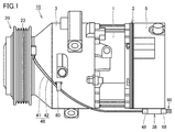
- FIG. 1 is a side view showing an appearance configuration of a variable displacement compressor for a vehicle (a compressor 10) according to Embodiment 1.
- FIG. 1 is a cross-sectional view showing an internal configuration of a variable displacement compressor for a vehicle (compressor 10) according to Embodiment 1.
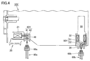
- FIG. 5 is an enlarged cross-sectional view showing an electromagnetic control valve 30, connectors 38, 48, and the like provided in the variable displacement compressor for a vehicle (compressor 10) according to the first embodiment. It is a figure which shows typically the variable displacement type compressor (compressor 10Y) for vehicles in the comparative example 1.
- FIG. It is a figure which shows typically the variable displacement type compressor (compressor 10Z) for vehicles in the comparative example 2.
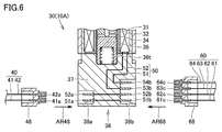
- FIG. 14 is an enlarged cross-sectional view showing an electromagnetic control valve 30, connectors 38, 48, and the like provided in a variable displacement compressor for a vehicle (compressor 10A) according to a second embodiment.
- FIG. 16 is an enlarged cross-sectional view showing an electromagnetic clutch 20, an electromagnetic control valve 30, connectors 38, 48, and the like provided in a variable displacement compressor for a vehicle (compressor 10B) in the third embodiment.
- FIG. 1 is a side view showing the appearance of the compressor 10.
- FIG. 2 is a cross-sectional view showing an internal configuration of the compressor 10.
- the compressor 10 includes a cylinder block 1, a piston 1b, a valve unit 2, a front housing 3, a rear housing 5, a rotating shaft 6, a circlip 6a, a swash plate 7 Link mechanism 7d, pair of shoes 7e, 7f, inclination angle reduction spring 8a, return spring 8b, lip seal 9a, bearings 9b, 9c, 9e, lug plate 9f, electromagnetic clutch 20, electromagnetic control valve 30, cable 40, wiring member 50, and connectors 38, 48.
- the connector 38 functions as the "first connector having the input terminal portion 38b and the output terminal portion 38a", and the connector 48 is connected to the "output terminal portion 38a of the first connector Function as a second connector.
- the electromagnetic control valve 30 functions as “one of the electromagnetic clutch 20 and the electromagnetic control valve 30", and the electromagnetic clutch 20 functions as “the other of the electromagnetic clutch 20 and the electromagnetic control valve 30".
- the cylinder block 1 is disposed between the front housing 3 and the rear housing 5.
- the cylinder block 1, the front housing 3 and the rear housing 5 constitute a housing of the compressor 10, and the rotary shaft 6 is accommodated inside thereof.
- a locking piece 80 (FIG. 1) is provided on the outer surface of the housing (here, the front housing 3).
- the locking piece 80 may be provided integrally with a member constituting the housing, or a clip or the like prepared separately from the housing may be attached to the housing so that the locking piece 80 is attached. It may be configured.
- a valve unit 2 is provided between the cylinder block 1 and the rear housing 5.
- Shaft holes 1 h and 3 h are respectively formed in the cylinder block 1 and the front housing 3, and the rotary shaft 6 is inserted into the shaft holes 1 h and 3 h.
- a bearing 9 c is provided between the shaft hole 1 h and the rotary shaft 6.
- a lip seal 9 a and a bearing 9 b are provided between the shaft hole 3 h and the rotating shaft 6. Power from an engine (not shown) is transmitted to the rotating shaft 6 via an electromagnetic clutch 20 described later.
- a crank chamber 9 is formed inside the cylinder block 1 and the front housing 3.
- the rotating shaft 6, the swash plate 7 and the lug plate 9f are arranged.
- a bearing 9 e is provided between the lug plate 9 f and the front housing 3.
- the swash plate 7 is connected to the rotary shaft 6, and the lug plate 9 f is fitted to the rotary shaft 6.
- a tilt angle reduction spring 8a is provided between the lug plate 9f and the swash plate 7, and the lug plate 9f and the swash plate 7 are connected to each other through a link mechanism 7d.
- the circlip 6 a is attached to the rotating shaft 6, and a return spring 8 b is provided between the circlip 6 a and the swash plate 7.
- a plurality of cylinder bores 1a are formed in the cylinder block 1, and one piston 1b is accommodated inside the plurality of cylinder bores 1a.
- a compression chamber 1 c is formed between the piston 1 b and the valve unit 2.
- Shoes 7e and 7f are provided between the piston 1b and the swash plate 7. The swash plate 7 is swung by being rotated together with the rotary shaft 6, and the swinging of the swash plate 7 is converted to the reciprocating motion of the piston 1b by the shoes 7e and 7f.
- the cylinder block 1 is formed with a passage 7 a and a passage 7 c (a part).
- the rear housing 5 is formed with passages 4a and 4b, a suction chamber 5a, a suction port 5c, a discharge chamber 5b, a discharge port 5d, an accommodation hole 5e and a passage 7c (remaining portion).
- the electromagnetic control valve 30 is accommodated in the accommodation hole 5e.
- the suction chamber 5a and the accommodation hole 5e are connected to each other by the passage 4a.
- the crank chamber 9 and the suction chamber 5a are connected to each other by the passage 7a, and the refrigerant gas in the crank chamber 9 is led to the suction chamber 5a through the passage 7a (also referred to as a bleed passage).
- the crank chamber 9 and the accommodation hole 5e are connected to each other by the passage 7c, and the discharge chamber 5b and the accommodation hole 5e are connected to each other by the passage 4b.
- the refrigerant gas in the discharge chamber 5b is introduced to the crank chamber 9 through the passages 4b and 7c (also referred to as an air supply passage).
- the air supply passage is opened and closed by an electromagnetic control valve 30 described later.
- the electromagnetic clutch 20 includes an electromagnetic coil 21 (first electromagnetic coil), a stator 22, a rotor 23, an armature 24, a hub 25, a bearing 26, and an elastic member 27.
- the electromagnetic coil 21 is incorporated in the stator 22.
- the stator 22 is fixed to the front housing 3 and located inside the rotor 23.
- the rotor 23 is rotatably supported by the boss 3 a via a bearing 26 provided on the outer peripheral side of the boss 3 a.
- the rotor 23 is connected to the engine via a belt (not shown).
- the armature 24 has a disk shape and is opposed to the rotor 23 in the axial direction.
- the hub 25 connects the armature 24 and the rotating shaft 6.
- the inner peripheral surface of the elastic member 27 is joined to the outer peripheral side of the hub 25, and the outer peripheral surface of the elastic member 27 is joined to the armature 24.
- a cable 40 is connected to the electromagnetic coil 21 of the electromagnetic clutch 20.
- the cable 40 has a length that can reach from a portion of the cable 40 connected to the electromagnetic coil 21 to a position near a connector 38 described later.
- a locking piece 80 (FIG. 1) provided on the front housing 3 regulates movement of the cable 40 by locking to the cable 40. Electric power from the outside (for example, a car battery) is supplied to the electromagnetic coil 21 through the cable 40.
- the cable 40 includes the power supply wiring 41 (second power supply wiring) and the ground wiring 42 (second ground wiring). From the electromagnetic clutch 20, the power supply side end and the ground side end of the electromagnetic coil 21 are drawn out.
- One end of the power supply wiring 41 is substantially non-detachably connected to the power supply side end of the electromagnetic coil 21 without a connector.
- One end of the grounding wire 42 is substantially non-removably connected to the ground side end of the electromagnetic coil 21 without a connector.
- the substantially non-removable connection aspect is an aspect in which the coil wire of the electromagnetic coil 21 and the wiring are connected to each other without the intervention of a connector.
- the substantially non-removable connection mode unlike in the connection mode using the connector, it is not planned to attach and detach the coil wire and the wiring. For example, there is a mode in which the metal fitting terminal attached to the tip of the coil wire and the wire portion exposed from the sheath at one end of the wire are directly connected so as to contact each other.
- FIG. 3 is an enlarged cross-sectional view of the electromagnetic control valve 30, the connector 48 and the like provided in the compressor 10.
- the connector 48 is formed of an insulating resin material.
- the connector 48 is a member provided separately from the electromagnetic clutch 20, and is connected to the electromagnetic clutch 20 (electromagnetic coil 21) via a cable 40.
- Bracket terminals 41 a and 42 a are fixed to the inside of the connector 48.
- the other end of the power supply wiring 41 is attached to the bracket terminal 41a, and the other end of the grounding wiring 42 is attached to the bracket terminal 42a. Electric power from the outside (for example, a car battery) is supplied to the electromagnetic coil 21 (FIG. 2) through the metal fitting terminals 41a and 42a and the cable 40 (power supply wiring 41, grounding wiring 42).
- the electromagnetic control valve 30 follows the valve body 31, the open spring 31 t, the electromagnetic coil 32 (second electromagnetic coil), the bellows 33, the spring 33 t, the housing cylinder 34, the fixed iron core 35, the movable iron core 36, It has a spring 36 t and a resin portion 37.
- a valve chamber 31s and a pressure sensing chamber 33s are formed.
- the solenoid control valve 30 further communicates with a suction pressure introducing port 33a communicating with the pressure sensing chamber 33s, a valve chamber port 31b communicating with the valve chamber 31s, a valve hole 31h communicating with the valve chamber 31s, and a valve hole 31h.
- a control port 31c is formed.
- the valve chamber 31s communicates with the discharge chamber 5b (FIG. 2) through the valve chamber port 31b and the passage 4b (FIG. 2).
- the pressure sensing chamber 33s is in communication with the suction chamber 5a (FIG. 2) through the suction pressure introducing port 33a and the passage 4a (FIG. 2).
- the control port 31c communicates with the crank chamber 9 (FIG. 2) through the passage 7c (FIG. 2).
- An open spring 31t is provided in the valve chamber 31s, and the open spring 31t biases the valve body 31 in a direction to open the valve hole 31h.
- a bellows 33 and a spring 33 t are provided in the pressure sensing chamber 33 s, and the bellows 33 is operatively connected to the valve body 31.
- the spring 33t biases the bellows 33 so as to extend toward the valve hole 31h.
- the biasing force of the spring 33 t acts on the valve body 31 in the direction of opening the valve hole 31 h.
- a housing cylinder 34 is provided inside the electromagnetic coil 32.
- the housing cylinder 34 has a bottomed cylindrical shape, and the opening of the housing cylinder 34 is fitted with the fixed iron core 35 adjacent to the valve chamber 31s.
- a movable iron core 36 is provided inside the storage cylinder 34.
- Movable iron core 36 has a cylindrical shape with a bottom, and can reciprocate in the space between fixed iron core 35 and the inner bottom surface of receiving cylinder 34.
- the movable core 36 is operatively connected to the valve body 31.
- a follow-up spring 36 t is provided between the inner bottom surface of the housing cylinder 34 and the movable core 36.
- the following spring 36 t biases the movable core 36 toward the fixed core 35.
- the biasing force of the follow-up spring 36t acts on the valve body 31 in the direction of closing the valve hole 31h.
- the elastic coefficient of the following spring 36t is smaller than the elastic coefficient of the open spring 31t.
- a wiring member 50 is connected to the electromagnetic coil 32 of the electromagnetic control valve 30. Electric power from the outside (for example, an on-board battery) is supplied to the electromagnetic coil 32 through the wiring member 50.
- the wiring member 50 includes the power supply wiring 51 (first power supply wiring) and the ground wiring 52 (first ground wiring).
- One end of the power supply wiring 51 is substantially non-detachably connected to the power supply side end of the electromagnetic coil 32 without a connector.
- One end of the ground wire 52 is substantially non-removably connected to the ground side end of the electromagnetic coil 32 without a connector.
- a resin portion 37 is integrally formed on the bottom of the storage cylinder 34 by resin molding.
- the resin portion 37 is formed of a resin material having an insulating property, and is fixed to the bottom of the housing cylinder 34 to fix the electromagnetic coil 32.
- a portion of the power supply wiring 51 located on one end side (electromagnetic coil 32 side) and a portion of the ground wiring 52 located on one end side (electromagnetic coil 32) side are sealed by a resin portion 37 ing.
- the connector 38 is integrated with the solenoid control valve 30 and is electrically connected to the solenoid control valve 30. Specifically, connector 38 is disposed at a position away from electromagnetic clutch 20, and connector 38 is provided integrally with resin portion 37 at a position opposite to housing cylinder 34 of resin portion 37. . The connector 38 is integrally formed with the resin portion 37 by the same member as the resin portion 37 integrated with the bottom portion of the storage cylinder 34. In the present embodiment, the wiring member 50 is integrated with the connector 38. A portion of the power supply wiring 51 located on the other end side and a portion of the ground wiring 52 located on the other end side are integrated with the connector 38.
- the connector 38 has an output terminal 38a and an input terminal 38b.
- the output terminal portion 38 a can be electrically connected to the electromagnetic clutch 20 via the cable 40, and the input terminal portion 38 b can be connected to the vehicle side connector 68.
- the electromagnetic coil 21 is electrically connected to the input terminal portion 38 b through the power supply wiring 41 and the ground wiring 42, and the electromagnetic coil 32 is connected to the input terminal portion 38 b through the power supply wiring 51 and the ground wiring 52.
- the output terminal portion 38a is a concave space formed inside the connector 38, and the metal fitting terminals 51a and 52a are fixed inside the output terminal portion 38a.
- the input terminal portion 38b is a concave space formed inside the connector 38, and the metal fitting terminals 51b, 52b, 53b are fixed inside the input terminal portion 38b.
- the other end of the power supply wiring 51 is attached to the bracket terminal 53b.
- the metal fitting terminal 51 a and the metal fitting terminal 51 b are electrically connected to each other in the connector 38 by the internal conductor.
- the metal fitting terminal 51a and the metal fitting terminal 51b may be integrally formed of one metal member.
- the metal fitting terminal 52 a and the metal fitting terminal 52 b are electrically connected to each other in the connector 38 by the internal conductor.
- the metal fitting terminal 52a and the metal fitting terminal 52b may be integrally formed of one metal member.
- the other end of the grounding wire 52 is connected to an internal conductor (or a member integrally forming the fitting terminals 52 a and 52 b) for electrically connecting the fitting terminal 52 a and the fitting terminal 52 b to each other.
- vehicle cable 60 and vehicle connector 68 A vehicle-side cable 60 is connected to the compressor 10 (FIGS. 1 and 2) via a vehicle-side connector 68.
- vehicle-side cable 60 extending from the vehicle main body has power supply wires 61 and 63 and a ground wire 62 (common ground wire).
- ground wire 62 common ground wire
- One end of the power supply wiring 61, one end of the grounding wiring 62, and one end of the power supply wiring 63 are integrated with the vehicle-side connector 68. The other end of each of these wires is connected to a not-shown vehicle battery or the like.
- the vehicle side connector 68 is formed of an insulating resin material.
- Metal fitting terminals 61c, 62c and 63c are fixed to the inside of the vehicle side connector 68.
- One end of the power supply wiring 61 is attached to the fitting terminal 61c
- one end of the grounding wiring 62 is attached to the fitting terminal 62c
- one end of the power supply wiring 63 is attached to the fitting terminal 63c.
- the power supply wiring 61 provided in the vehicle side cable 60 is electrically connected to the power supply side end of the electromagnetic coil 21 through the bracket terminals 61c, 51b, 51a, 41a and the power supply wiring 41.
- the grounding wire 62 provided in the vehicle-side cable 60 is electrically connected to the ground side end of the electromagnetic coil 32 through the fitting terminals 62c and 52b and the grounding wire 52, and the fitting terminals 62c, 52b, 52a, It is electrically connected to the ground side end of the electromagnetic coil 21 through 42 a and the ground wire 42. That is, both the ground wiring 42 and the ground wiring 52 are electrically connected to the ground wiring 62 provided in the vehicle side connector 68.
- the power supply wire 63 provided in the vehicle-side cable 60 is electrically connected to the power supply side end of the electromagnetic coil 32 through the bracket terminals 63 c and 53 b and the power supply wire 51.
- the electromagnetic clutch 20 switches the connection and disconnection of the power from the external drive source (for example, the engine) to the rotating shaft 6 by the operation of the electromagnetic coil 21.
- the electromagnetic clutch 20 By switching the connection and disconnection of the power from the external drive source to the rotary shaft 6 by the electromagnetic clutch 20, the rotary shaft 6 and thus the compressor 10 can be driven at appropriate timing.
- the valve opening degree of the valve hole 31h defined by the valve body 31 is a pressing force acting on the valve body 31 by the excitation of the electromagnetic coil 32, and a pressing force acting on the valve body 31 by fluctuation of suction pressure in the pressure sensing chamber 33s. It is determined by the balance between the pressure and the pressing force exerted on the valve body 31 by the open spring 31t.
- the valve opening degree of the valve hole 31h decreases, the refrigerant gas flowing from the discharge chamber 5b into the crank chamber 9 via the passage 4b, the valve chamber port 31b, the valve chamber 31s, the valve hole 31h, the control port 31c and the passage 7c. Flow rate decreases.
- the refrigerant gas in the crank chamber 9 is led to the suction chamber 5a via the passage 7a.
- the pressure in the crank chamber 9 decreases, and the inclination angle of the swash plate 7 is changed according to the differential pressure between the inside of the crank chamber 9 and the inside of the cylinder bore 1a.
- valve opening degree of the valve hole 31h increases, the refrigerant gas flowing from the discharge chamber 5b into the crank chamber 9 via the passage 4b, the valve chamber port 31b, the valve chamber 31s, the valve hole 31h, the control port 31c and the passage 7c.
- Flow rate increases.
- the valve opening degree of the valve hole 31h increases, the pressure in the crank chamber 9 rises, and the inclination angle of the swash plate 7 is changed according to the differential pressure between the crank chamber 9 and the cylinder bore 1a. That is, as the internal pressure of the crank chamber 9 decreases, the inclination angle of the swash plate 7 increases, and the displacement of the compressor 10 increases.
- the inclination angle of the swash plate 7 decreases, and the displacement of the compressor 10 decreases.
- the opening and closing operation of the electromagnetic control valve 30 changes in accordance with the magnitude of the input current value to the electromagnetic coil 32.
- the solenoid control valve 30 adjusts the discharge capacity of the refrigerant gas of the compressor 10 by changing the tilt angle of the swash plate 7 by the operation of the electromagnetic coil 32 so as to maintain the set suction pressure.
- the compressor 10 can configure the refrigeration circuit of the vehicle together with the external circuit (not shown), and can air-condition the vehicle interior and the like.
- FIG. 4 is a view schematically showing the compressor 10Y in the first comparative example.
- the compressor 10Y in the comparative example 1 includes a connector 48 integrated with the wiring member 40Y and a connector 38 integrated with the wiring member 50Y. Unlike the first embodiment, the configuration in which the connector 48 and the connector 38 are directly connected to each other is not employed in the compressor 10Y.
- the connector 48 is connected to a vehicle connector 68a integrated with the vehicle cable 60a
- the connector 38 is connected to a vehicle connector 68b integrated with the vehicle cable 60b.
- a vehicle-side cable 60a for supplying power to the electromagnetic coil 21 and a vehicle-side cable 60b for supplying power to the electromagnetic coil 32 are disposed separately from each other.
- a total of two cables (two bundles) of the vehicle cables 60a and 60b need to be prepared.
- the total number of connectors used for connection between the compressor 10 and the vehicle main body is a total of three connectors 38, 48 and the vehicle side connector 68, but the comparative example In the case of 1, there are a total of four connectors 38, 48 and vehicle side connectors 68a, 68b.
- the cable 40 can be fixed to the housing by one locking piece 80.
- FIG. 5 is a view schematically showing a compressor 10Z in Comparative Example 2.
- the compressor 10Z in the comparative example 2 includes a connector 48 integrated with the cable 40, a connector 38 integrated with the wiring member 50, a sub-harness 90, and connectors 90a and 90b. Unlike in the first embodiment, the configuration in which the connector 48 and the connector 38 are directly connected to each other is not adopted in the compressor 10Z.
- the connector 48 has an output terminal portion 48 a and an input terminal portion 48 b.
- the connector 90a integrated with one end of the sub-harness 90 is connected to the output terminal portion 48a.
- the connector 90 b integrated with the other end of the sub harness 90 is connected to the connector 38.
- a vehicle-side connector 68 integrated with the vehicle-side cable 60 is connected to the input terminal portion 48 b of the connector 48.
- the compressor 10 ⁇ / b> Z unlike the case of the compressor 10 ⁇ / b> Y in the comparative example 1 described above, one (one bundle) of the vehicle side cables 60 may be prepared on the vehicle body side.
- the number of parts and the part cost are increased as compared to the case of the first embodiment in that the sub-harness 90 is used.
- the total number of connectors used for connection between the compressor 10Z and the vehicle body is five in total in the case of Comparative Example 2 including the connectors 38, 48, 90a, 90b and the vehicle side connector 68. More than the case of mode 1 (three).
- the total number of connectors used for connection between the compressor 10 and the vehicle main body is three, and can be smaller than in the comparative examples 1 and 2. There is a merit in that there is one.
- Embodiment 1 and Comparative Example 1 (FIG. 4) are compared, in the compressor 10 of Embodiment 1, one (one bundle) of the vehicle side cables 60 is prepared as the vehicle body side. There is a merit in that it is good.
- Embodiment 1 and Comparative Example 2 FIG. 5
- the compressor 10 of Embodiment 1 is advantageous in that it does not include the sub-harness 90 and the number of parts and the cost of parts are small. is there.
- the cables and connectors used to energize the electromagnetic clutch 20 and the electromagnetic control valve 30 are configured with a smaller number of parts compared to the cases of the comparative examples 1 and 2, It is possible to achieve space. Therefore, in the case of the compressor 10, the range in which the peripheral devices of the compressor 10 can be arranged can be expanded more easily than in the cases of Comparative Examples 1 and 2, and space saving can be achieved. It is also possible to facilitate the work.
- the connector 38 is integrated with the solenoid control valve 30. Compared with the case where the connector 38 is not integrated with the solenoid control valve 30 (e.g., compared to the case where the connector 38 is provided apart from the resin portion 37), space saving is achieved. In particular, since the connector 38 is integrally provided in the resin portion 37, further space saving is achieved.
- the grounding wire 52 (first grounding wire) and the grounding wire 42 (second grounding wire) are both provided to the vehicle-side connector 68. It is electrically connected to (common ground line).
- the compressor 10 and the vehicle main body side can be connected by the vehicle side cable 60 which has a total of three wiring of the wiring 61, 63 for power supply, and the wiring 62 for grounding.
- a locking piece 80 is provided on the outer surface of the housing (here, the front housing 3).
- the locking piece 80 regulates movement of the cable 40 by locking to the cable 40.
- FIG. 6 is an enlarged cross-sectional view of the electromagnetic control valve 30, the connectors 38, 48, and the like provided in the compressor 10A.
- the compressors 10 and 10A are different in the following points.
- the grounding wire 52 on the electromagnetic control valve 30 side and the grounding wire 42 on the electromagnetic clutch 20 (see FIG. 2) side are not electrically shared.
- the metal fitting terminals 51a and 52a are fixed inside the output terminal portion 38a, and the metal fitting terminals 51b, 52b, 53b and 54b are fixed inside the input terminal portion 38b.
- Metal fitting terminals 61c, 62c, 63c and 64c are fixed to the inside of the vehicle side connector 68.
- the power supply wiring 61 provided in the vehicle-side cable 60 is electrically connected to the power supply side end of the electromagnetic coil 21 (FIG. 2) through the bracket terminals 61c, 51b, 51a, 41a and the power supply wiring 41.
- the grounding wire 62 provided in the vehicle-side cable 60 is electrically connected to the grounding side end of the electromagnetic coil 21 (FIG. 2) through the bracket terminals 62c, 52b, 52a, 42a and the grounding wire 42.
- the power supply wire 63 provided in the vehicle-side cable 60 is electrically connected to the power supply side end of the electromagnetic coil 32 through the bracket terminals 63 c and 53 b and the power supply wire 51.
- the grounding wire 64 provided in the vehicle-side cable 60 is electrically connected to the grounding end of the electromagnetic coil 32 through the bracket terminals 64 c and 54 b and the grounding wire 52.
- the connector is configured with a smaller number of parts and space saving is achieved. Therefore, even in the case of the compressor 10A, the range in which the peripheral devices of the compressor 10A can be arranged can be expanded more easily than in the cases of the comparative examples 1 and 2, and space saving can be achieved to the vehicle body of the compressor 10A. It is possible to facilitate the installation work of
- both of the ground wire 42 from the electromagnetic coil 21 and the ground wire 52 from the electromagnetic coil 32 are connected to the vehicle cable 60, and the earth is secured through the vehicle cable 60.
- a ground may be secured for one or both of the grounding wires 42 and 52 without the vehicle-side cable 60.
- the grounding wires 42 and 52 may be directly connected to, for example, the housing of the compressor, and the earth may be secured through the housing or the like.
- FIG. 7 is an enlarged sectional view showing the electromagnetic clutch 20, the electromagnetic control valve 30, the connectors 38, 48 and the like provided in the compressor 10B.
- the compressors 10 and 10B are different in the following points.
- the connector 48 functions as the “first connector having the input terminal portion 48b and the output terminal portion 48a"
- the connector 38 is the “second connector connected to the output terminal portion 48a”.
- the electromagnetic clutch 20 functions as "one of the electromagnetic clutch 20 and the electromagnetic control valve 30"
- the electromagnetic control valve 30 functions as "the other of the electromagnetic clutch 20 and the electromagnetic control valve 30".
- the wiring member 40B is connected to the electromagnetic coil 21 of the electromagnetic clutch 20. Electric power from the outside (for example, a car battery) is supplied to the electromagnetic coil 21 through the wiring member 40B.
- the wiring member 40B includes a power supply wiring 41 (first power supply wiring) and a ground wiring 42 (first ground wiring). From the electromagnetic clutch 20, the power supply side end and the ground side end of the electromagnetic coil 21 are drawn out.
- One end of the power supply wiring 41 is substantially non-detachably connected to the power supply side end of the electromagnetic coil 21 without a connector.
- One end of the grounding wire 42 is substantially non-removably connected to the ground side end of the electromagnetic coil 21 without a connector.
- a resin portion 47 is integrally formed with the electromagnetic coil 21 by resin molding.
- the resin portion 47 is formed of a resin material having an insulating property, and is integrated with the electromagnetic coil 21 and the stator 22 to fix the electromagnetic coil 21.
- a portion of the power supply wiring 41 located on one end side (the electromagnetic coil 21 side) and a portion of the ground wiring 42 located on the one end side (the electromagnetic coil 21) side are sealed by the resin portion 47 ing.
- the connector 48 is integrated with the electromagnetic clutch 20 and electrically connected to the electromagnetic clutch 20. Specifically, the connector 48 is disposed at a position away from the electromagnetic control valve 30, and the connector 48 is provided integrally with the electromagnetic coil 21 at a position opposite to the electromagnetic coil 21 in the resin portion 47. There is.
- the connector 48 is integrally formed with the resin portion 47 by the same member as the resin portion 47 integrated with the electromagnetic coil 21.
- the wiring member 40B is integrated with the connector 48. A portion of the power supply wiring 41 located on the other end side and a portion of the ground wiring 42 located on the other end side are integrated with the connector 48.
- the connector 48 has an output terminal portion 48 a and an input terminal portion 48 b.
- the output terminal portion 48 a can be electrically connected to the electromagnetic control valve 30 via the cable 50 B, and the input terminal portion 48 b can be connected to the vehicle side connector 68.
- the electromagnetic coil 21 is connected to the input terminal portion 48b through the power supply wiring 41 and the ground wiring 42, and the electromagnetic coil 32 is electrically connected to the input terminal portion 48b through the power supply wiring 51 and the ground wiring 52.
- the output terminal portion 48a is a concave space formed inside the connector 48, and the metal fitting terminals 51a and 52a are fixed inside the output terminal portion 48a.
- the input terminal portion 48b is a concave space formed inside the connector 48, and the metal fitting terminals 51b, 52b, 53b are fixed inside the input terminal portion 48b.
- the other end of the power supply wiring 41 is attached to the bracket terminal 53b.
- the metal fitting terminal 51 a and the metal fitting terminal 51 b are electrically connected to each other in the connector 48 by the internal conductor.
- the metal fitting terminal 51a and the metal fitting terminal 51b may be integrally formed of one metal member.
- the metal fitting terminal 52 a and the metal fitting terminal 52 b are electrically connected to each other in the connector 48 by the internal conductor.
- the metal fitting terminal 52a and the metal fitting terminal 52b may be integrally formed of one metal member.
- the other end of the grounding wire 42 is connected to an internal conductor (or a member integrally forming the fitting terminals 52a and 52b) for electrically connecting the fitting terminal 52a and the fitting terminal 52b to each other.
- a cable 50 ⁇ / b> B is connected to the electromagnetic coil 32 of the electromagnetic control valve 30. Power from the outside (for example, a car battery) is supplied to the electromagnetic coil 32 through the cable 50B.
- the cable 50B has a length that can reach from the portion of the cable 50B connected to the electromagnetic coil 32 to a position near the connector 48.
- a locking piece 80 (see FIG. 1) may be provided on the outer surface of the front housing 3 so that the locking piece 80 restricts the movement of the cable 50B.
- the cable 50B includes a power supply wiring 51 (second power supply wiring) and a ground wiring 52 (second ground wiring).
- One end of the power supply wiring 51 is substantially non-detachably connected to the power supply side end of the electromagnetic coil 32 without a connector.
- One end of the ground wire 52 is substantially non-removably connected to the ground side end of the electromagnetic coil 32 without a connector.
- a resin portion 37 is integrally formed on the bottom of the storage cylinder 34 by resin molding.
- the resin portion 37 is formed of a resin material having an insulating property, and is fixed to the bottom of the housing cylinder 34 to fix the electromagnetic coil 32.
- a portion of the power supply wiring 51 located on one end side (electromagnetic coil 32 side) and a portion of the ground wiring 52 located on one end side (electromagnetic coil 32) side are sealed by a resin portion 37 ing.
- the other end of the power supply wiring 51 and the other end of the grounding wiring 52 are drawn from the resin portion 37 to the outside of the electromagnetic control valve 30 and integrated with the connector 38.
- the connector 38 is a member provided separately from the electromagnetic control valve 30, and is connected to the electromagnetic control valve 30 (the electromagnetic coil 32) via the cable 50B. Bracket terminals 51t and 52t are fixed to the inside of the connector 38. The other end of the power supply wiring 51 is attached to the fitting terminal 51t, and the other end of the grounding wiring 52 is attached to the fitting terminal 52t. Electric power from the outside (for example, an on-vehicle battery) is supplied to the electromagnetic coil 32 through the bracket terminals 51t and 52t and the cable 50B (the power supply wiring 51, the grounding wiring 52).
- a vehicle-side cable 60 extending from the vehicle main body includes power supply wires 61 and 63 and a ground wire 62 (common ground wire).
- One end of the power supply wiring 61, one end of the grounding wiring 62, and one end of the power supply wiring 63 are integrated with the vehicle-side connector 68. The other end of each of these wires is connected to a not-shown vehicle battery or the like.
- the vehicle side connector 68 is formed of an insulating resin material.
- Metal fitting terminals 61c, 62c and 63c are fixed to the inside of the vehicle side connector 68.
- One end of the power supply wiring 61 is attached to the fitting terminal 61c
- one end of the grounding wiring 62 is attached to the fitting terminal 62c
- one end of the power supply wiring 63 is attached to the fitting terminal 63c.
- the power supply wiring 61 provided in the vehicle side cable 60 is electrically connected to the power supply side end of the electromagnetic coil 32 through the bracket terminals 61c, 51b, 51a, 51t and the power supply wiring 51.
- the grounding wire 62 provided in the vehicle side cable 60 is electrically connected to the ground side end of the electromagnetic coil 21 through the fitting terminals 62c and 52b and the grounding wire 42, and the fitting terminals 62c, 52b, 52a, It is electrically connected to the ground side end of the electromagnetic coil 32 through 52t and the ground wire 52. That is, both the ground wiring 42 and the ground wiring 52 are electrically connected to the ground wiring 62 provided in the vehicle side connector 68.
- the power supply wiring 63 provided in the vehicle-side cable 60 is electrically connected to the power supply side end of the electromagnetic coil 21 through the bracket terminals 63 c and 53 b and the power supply wiring 41.
- the total number of connectors used for connection between the compressor 10B and the vehicle main body is three, which can be smaller than in the comparative examples 1 and 2.
- the compressor 10B of Embodiment 3 When Embodiment 3 and Comparative Example 1 (FIG. 4) are compared, in the compressor 10B of Embodiment 3, one (one bundle) of the vehicle side cables 60 is prepared as the vehicle main body side. There is a merit in that it is good.
- Embodiment 3 and Comparative Example 2 (FIG. 5) are compared, the compressor 10B of Embodiment 3 is advantageous in that it does not include the sub-harness 90 and the number of parts and the cost of parts are small. is there.
- the cables and connectors used to energize the electromagnetic clutch 20 and the electromagnetic control valve 30 are configured with a smaller number of parts compared to the cases of the comparative examples 1 and 2, and thus saving the cost It is possible to achieve space. Therefore, even in the case of the compressor 10B, the range in which the peripheral devices of the compressor 10B can be arranged can be expanded more easily than in the cases of Comparative Examples 1 and 2, and space saving can be achieved. It is also possible to facilitate the mounting operation on the main body.
- the connector 48 is integrated with the electromagnetic clutch 20. Compared with the case where the connector 48 is not integrated with the electromagnetic clutch 20 (for example, compared to the case where the connector 48 is provided apart from the resin portion 47), space saving is achieved. In particular, since the connector 48 is integrally provided in the resin portion 47, further space saving is achieved.
- the grounding wire 42 (first grounding wire) and the grounding wire 52 (second grounding wire) are both included in the grounding cable 62 provided in the vehicle-side cable 60. It is electrically connected to (common ground line).
- the compressor 10B can be connected to the vehicle main body side by the vehicle-side cable 60 having a total of three wirings of the power supply wirings 61 and 63 and the ground wiring 62.
- a locking piece 80 (FIG. 1) is provided on the outer surface of the housing (here, the front housing 3).
- the locking piece 80 regulates movement of the cable 50B by locking to the cable 50B.
- the crank chamber 9 and the suction chamber 5a are connected to each other by the passage 7a, and the refrigerant gas in the crank chamber 9 is led to the suction chamber 5a through the passage 7a (also referred to as a bleed passage). .
- the refrigerant gas in the discharge chamber 5b is introduced to the crank chamber 9 through the passages 4b and 7c (also referred to as an air supply passage).
- electromagnetic control valve 30 stated that this air supply passage is opened and closed
- electromagnetic control valve 30 may be constituted so that passage 7a (bleed passage) may be opened and closed. Even when the configuration is adopted, it is possible to obtain the same operation and effect as those of the above-described embodiments.
Landscapes
- Engineering & Computer Science (AREA)
- General Engineering & Computer Science (AREA)
- Mechanical Engineering (AREA)
- Physics & Mathematics (AREA)
- Electromagnetism (AREA)
- Compressors, Vaccum Pumps And Other Relevant Systems (AREA)
- Compressor (AREA)
- Magnetically Actuated Valves (AREA)
- Control Of Positive-Displacement Pumps (AREA)
Abstract
Description
図1から図3を参照して、実施の形態1における車両用可変容量型圧縮機(以下、単に圧縮機10ともいう)について説明する。図1は、圧縮機10の外観構成を示す側面図である。図2は、圧縮機10の内部構成を示す断面図である。
図1および図2(主として図2)に示すように、圧縮機10は、シリンダブロック1、ピストン1b、弁ユニット2、フロントハウジング3、リヤハウジング5、回転軸6、サークリップ6a、斜板7、リンク機構7d、一対のシュー7e,7f、傾角縮小ばね8a、復帰ばね8b、リップシール9a、軸受9b,9c,9e、ラグプレート9f、電磁クラッチ20、電磁制御弁30、ケーブル40、配線部材50、およびコネクタ38,48を備える。
フロントハウジング3の前端側には、円筒状のボス部3aが形成される。回転軸6は、ボス部3aの内側を通過するように配置され、回転軸6の前端部は電磁クラッチ20を介して図示しないエンジン(外部駆動源の一例)に作動連結される。電磁クラッチ20は、電磁コイル21(第1電磁コイル)、ステータ22、ロータ23、アーマチュア24、ハブ25、軸受26、および、弾性部材27を有する。
図3は、圧縮機10に備えられる電磁制御弁30およびコネクタ48等を拡大して示す断面図である。図2,図3に示すように、給電用配線41の他端および接地用配線42の他端は、コネクタ48と一体化されている。コネクタ48は、絶縁性を有する樹脂材料により形成されている。コネクタ48は、電磁クラッチ20とは別に設けられた部材であり、電磁クラッチ20(電磁コイル21)とはケーブル40を介して接続される。コネクタ48の内側には、金具端子41a,42aが固定されている。給電用配線41の他端は金具端子41aに取り付けられており、接地用配線42の他端は金具端子42aに取り付けられている。外部(たとえば車載バッテリ)からの電力は、金具端子41a,42aおよびケーブル40(給電用配線41、接地用配線42)を通して電磁コイル21(図2)に供給される。
図3に示すように、電磁制御弁30は、弁体31、開放ばね31t、電磁コイル32(第2電磁コイル)、ベローズ33、ばね33t、収容筒34、固定鉄心35、可動鉄心36、追従ばね36tおよび樹脂部37を有する。
本実施の形態では、コネクタ38が電磁制御弁30と一体化されるとともに電磁制御弁30に電気的に接続されている。具体的には、コネクタ38は電磁クラッチ20から離れた位置に配置され、樹脂部37のうちの収容筒34とは反対側の位置に、コネクタ38が樹脂部37と一体的に設けられている。コネクタ38は、収容筒34の底部と一体化されている樹脂部37と同一の部材によって、樹脂部37と一体的に形成されている。本実施の形態においては、配線部材50がコネクタ38と一体化されている。給電用配線51のうちの他端側に位置する部分と、接地用配線52のうちの他端側に位置する部分とが、コネクタ38と一体化されている。
圧縮機10(図1,図2)には、車両側コネクタ68を介して車両側ケーブル60が接続される。図3を参照して、具体的には、車両本体から延びる車両側ケーブル60は、電源用配線61,63と、接地用配線62(共通接地線)とを有する。電源用配線61の一端と、接地用配線62の一端と、電源用配線63の一端とは、車両側コネクタ68と一体化されている。これらの各配線の他端は、図示しない車載バッテリなどに接続されている。
コネクタ48を出力端子部38aに差し込むことで(矢印AR48)、コネクタ48が出力端子部38aに接続され、コネクタ48をコネクタ38に接続することができる。出力端子部38aは、コネクタ38から電磁コイル21側に向かう方向に開口しており、出力端子部38aに接続されたケーブル40が急峻に湾曲すること(ケーブル40が過度に捻じ曲げられること)が抑制されている。車両側コネクタ68を入力端子部38bに差し込むことで(矢印AR68)、車両側コネクタ68が入力端子部38bに接続され、車両側コネクタ68をコネクタ38に接続することができる。これにより車両側ケーブル60がケーブル40および配線部材50に電気的に接続される。車両側(車両側ケーブル60側)からの電磁クラッチ20および電磁制御弁30への通電は、入力端子部38b(金具端子51b,52b,53b)を介して行われる。
電磁コイル21への通電時には、ステータ22がアーマチュア24を磁力により吸引し、アーマチュア24は弾性部材27の弾性力に抗して移動し、ロータ23に当接する。アーマチュア24、ハブ25および回転軸6にロータ23からの動力が伝達され、アーマチュア24、ハブ25および回転軸6はロータ23と一体的に回転する。
電磁コイル32への通電時には、電磁コイル32への入力電流値に応じた吸引力が、固定鉄心35と可動鉄心36との間に発生する。この吸引力は、弁体31に対して弁孔31hを閉塞する方向に作用する。吸入室5aから通路4aおよび吸入圧力導入ポート33aを通じて感圧室33sに導入される吸入圧力が変動し、この吸入圧力の変動に応じてベローズ33が変位する。ベローズ33を変位させる作動力は弁体31に伝達される。
実施の形態1における圧縮機10による作用および効果について、図4および図5にそれぞれ示される比較例1,2の作用および効果と対比しながら説明する。
図4は、比較例1における圧縮機10Yを模式的に示す図である。比較例1における圧縮機10Yは、配線部材40Yと一体化されたコネクタ48と、配線部材50Yと一体化されたコネクタ38とを備えている。実施の形態1の場合とは異なり、コネクタ48とコネクタ38とが互いに直接的に接続されるという構成は圧縮機10Yでは採用されていない。コネクタ48には、車両側ケーブル60aと一体化された車両側コネクタ68aが接続され、コネクタ38には、車両側ケーブル60bと一体化された車両側コネクタ68bが接続される。
図5は、比較例2における圧縮機10Zを模式的に示す図である。比較例2における圧縮機10Zは、ケーブル40と一体化されたコネクタ48と、配線部材50と一体化されたコネクタ38、サブハーネス90と、コネクタ90a,90bとを備えている。実施の形態1の場合とは異なり、コネクタ48とコネクタ38とが互いに直接的に接続されるという構成は圧縮機10Zでも採用されていない。コネクタ48は、出力端子部48aおよび入力端子部48bを有する。サブハーネス90の一端と一体化されたコネクタ90aは、出力端子部48aに接続される。サブハーネス90の他端と一体化されたコネクタ90bは、コネクタ38に接続される。コネクタ48の入力端子部48bには、車両側ケーブル60と一体化された車両側コネクタ68が接続される。
実施の形態1における圧縮機10によれば、圧縮機10と車両本体側との接続に利用されるコネクタの総数が3つであり、比較例1,2の場合よりも少なくすることが可能であるという点でメリットがある。実施の形態1と比較例1(図4)とを対比した場合には、実施の形態1の圧縮機10は、車両本体側として車両側ケーブル60の1本(1束)が準備されていればよいという点でメリットがある。実施の形態1と比較例2(図5)とを対比した場合には、実施の形態1の圧縮機10は、サブハーネス90を備えておらず部品点数および部品コストが少ないという点でメリットがある。
図6を参照して、実施の形態2における圧縮機10Aについて説明する。図6は、圧縮機10Aに備えられる電磁制御弁30およびコネクタ38,48等を拡大して示す断面図である。圧縮機10,10Aは以下の点において相違している。
図7を参照して、実施の形態3における圧縮機10Bについて説明する。図7は、圧縮機10Bに備えられる電磁クラッチ20、電磁制御弁30およびコネクタ38,48等を拡大して示す断面図である。圧縮機10,10Bは以下の点において相違している。
具体的には、電磁クラッチ20の電磁コイル21には、配線部材40Bが接続されている。外部(たとえば車載バッテリ)からの電力は配線部材40Bを通して電磁コイル21に供給される。配線部材40Bは、給電用配線41(第1給電用配線)および接地用配線42(第1接地用配線)を含む。電磁クラッチ20からは、電磁コイル21の給電側端部と接地側端部とが引き出されている。電磁コイル21の給電側端部には、コネクタを介さずに、給電用配線41の一端が実質的に着脱不能に接続されている。電磁コイル21の接地側端部には、コネクタを介さずに接地用配線42の一端が実質的に着脱不能に接続されている。
本実施の形態では、コネクタ48が電磁クラッチ20と一体化されるとともに電磁クラッチ20に電気的に接続されている。具体的には、コネクタ48は電磁制御弁30から離れた位置に配置され、樹脂部47のうちの電磁コイル21とは反対側の位置に、コネクタ48が電磁コイル21と一体的に設けられている。コネクタ48は、電磁コイル21と一体化されている樹脂部47と同一の部材によって、樹脂部47と一体的に形成されている。本実施の形態においては、配線部材40Bがコネクタ48と一体化されている。給電用配線41のうちの他端側に位置する部分と、接地用配線42のうちの他端側に位置する部分とが、コネクタ48と一体化されている。
電磁制御弁30の電磁コイル32には、ケーブル50Bが接続されている。外部(たとえば車載バッテリ)からの電力は、ケーブル50Bを通して電磁コイル32に供給される。ケーブル50Bは、ケーブル50Bのうちの電磁コイル32に接続された部分からコネクタ48の近傍位置にまで到達可能な長さを有している。フロントハウジング3の外表面に係止片80(図1参照)を設けて、係止片80によってケーブル50Bの移動を規制するように構成されてもよい。
コネクタ38は、電磁制御弁30とは別に設けられた部材であり、電磁制御弁30(電磁コイル32)とはケーブル50Bを介して接続される。コネクタ38の内側には、金具端子51t,52tが固定されている。給電用配線51の他端は金具端子51tに取り付けられており、接地用配線52の他端は金具端子52tに取り付けられている。外部(たとえば車載バッテリ)からの電力は、金具端子51t,52tおよびケーブル50B(給電用配線51、接地用配線52)を通して電磁コイル32に供給される。
車両本体から延びる車両側ケーブル60は、電源用配線61,63と、接地用配線62(共通接地線)とを有する。電源用配線61の一端と、接地用配線62の一端と、電源用配線63の一端とは、車両側コネクタ68と一体化されている。これらの各配線の他端は、図示しない車載バッテリなどに接続されている。
コネクタ38を出力端子部48aに差し込むことで、コネクタ38が出力端子部48aに接続され、コネクタ38をコネクタ48に接続することができる。車両側コネクタ68を入力端子部48bに差し込むことで、車両側コネクタ68が入力端子部48bに接続され、車両側コネクタ68をコネクタ48に接続することができる。これにより車両側ケーブル60が配線部材40Bおよびケーブル50Bに電気的に接続される。車両側(車両側ケーブル60側)からの電磁クラッチ20および電磁制御弁30への通電は、入力端子部48b(金具端子51b,52b,53b)を介して行われる。
上述の各実施の形態においては、クランク室9と吸入室5aとが、通路7aにより互いに接続され、クランク室9内の冷媒ガスは、通路7a(抽気通路ともいう)を通して吸入室5aに導かれる。吐出室5b内の冷媒ガスは、通路4b,7c(給気通路ともいう)を通してクランク室9に導かれる。上述の実施の形態1においては、電磁制御弁30がこの給気通路を開閉すると述べたが、電磁制御弁30は、通路7a(抽気通路)を開閉するように構成されてもよい。当該構成が採用される場合であっても、上述の各実施の形態と同様の作用および効果を得ることが可能である。
Claims (6)
- 車両用可変容量型圧縮機であって、
外部駆動源からの動力を受けて回転する回転軸と、
第1電磁コイルを有し、前記外部駆動源から前記回転軸への前記動力の断接を前記第1電磁コイルの作動により切り換える電磁クラッチと、
第2電磁コイルを有し、前記第2電磁コイルの作動により前記車両用可変容量型圧縮機の吐出容量を制御する電磁制御弁と、
入力端子部および出力端子部を有し、前記電磁クラッチおよび前記電磁制御弁のうちの一方に一体化されるとともに前記一方に電気的に接続され、前記電磁クラッチおよび前記電磁制御弁のうちの他方から離れた位置に配置され、前記入力端子部が車両側コネクタに接続可能であり、前記出力端子部が前記他方に電気的に接続可能である第1コネクタと、
前記他方とは別に設けられ、前記他方とはケーブルを介して接続され、前記第1コネクタの前記出力端子部に接続される第2コネクタと、を備え、
車両側からの前記電磁クラッチおよび前記電磁制御弁への通電は、前記入力端子部を介して行われる、
車両用可変容量型圧縮機。 - 前記第1コネクタは、前記電磁制御弁と一体化され、
前記電磁制御弁は、樹脂成形により形成され前記第2電磁コイルを固定している樹脂部を有し、
前記第1コネクタは、前記樹脂部と一体的に設けられている、
請求項1に記載の車両用可変容量型圧縮機。 - 前記第2電磁コイルは、第1給電用配線および第1接地用配線を介して前記入力端子部に接続されており、
前記ケーブルは、第2給電用配線および第2接地用配線を含み、
前記第1電磁コイルは、前記第2給電用配線および前記第2接地用配線を介して前記入力端子部に電気的に接続されており、
前記第1接地用配線および前記第2接地用配線はいずれも、前記車両側コネクタに設けられた共通接地線に電気的に接続される、
請求項2に記載の車両用可変容量型圧縮機。 - 前記第1コネクタは、前記電磁クラッチと一体化され、
前記電磁クラッチは、樹脂成形により形成され前記第1電磁コイルを固定している樹脂部を有し、
前記第1コネクタは、前記樹脂部と一体的に設けられている、
請求項1に記載の車両用可変容量型圧縮機。 - 前記第1電磁コイルは、第1給電用配線および第1接地用配線を介して前記入力端子部に接続されており、
前記ケーブルは、第2給電用配線および第2接地用配線を含み、
前記第2電磁コイルは、前記第2給電用配線および前記第2接地用配線を介して前記入力端子部に電気的に接続されており、
前記第1接地用配線および前記第2接地用配線はいずれも、前記車両側コネクタに設けられた共通接地線に電気的に接続される、
請求項4に記載の車両用可変容量型圧縮機。 - 前記回転軸を収容しているハウジングの外表面には、前記ケーブルに係止することによって前記ケーブルの移動を規制する係止片が設けられている、請求項1から5のいずれか1項に記載の車両用可変容量型圧縮機。
Priority Applications (5)
| Application Number | Priority Date | Filing Date | Title |
|---|---|---|---|
| BR112020005254-0A BR112020005254A2 (pt) | 2017-09-27 | 2018-09-10 | compressor do tipo de deslocamento variável para veículo |
| CN201880062258.0A CN111133194A (zh) | 2017-09-27 | 2018-09-10 | 车辆用可变容量型压缩机 |
| US16/649,360 US20200248678A1 (en) | 2017-09-27 | 2018-09-10 | Variable displacement-type compressor for vehicle |
| DE112018004311.8T DE112018004311B4 (de) | 2017-09-27 | 2018-09-10 | Kompressor mit variabler Verdrängung für Fahrzeug |
| KR1020207010328A KR20200051026A (ko) | 2017-09-27 | 2018-09-10 | 차량용 가변 용량형 압축기 |
Applications Claiming Priority (2)
| Application Number | Priority Date | Filing Date | Title |
|---|---|---|---|
| JP2017-186798 | 2017-09-27 | ||
| JP2017186798A JP6870553B2 (ja) | 2017-09-27 | 2017-09-27 | 車両用可変容量型圧縮機 |
Publications (1)
| Publication Number | Publication Date |
|---|---|
| WO2019065183A1 true WO2019065183A1 (ja) | 2019-04-04 |
Family
ID=65901330
Family Applications (1)
| Application Number | Title | Priority Date | Filing Date |
|---|---|---|---|
| PCT/JP2018/033447 Ceased WO2019065183A1 (ja) | 2017-09-27 | 2018-09-10 | 車両用可変容量型圧縮機 |
Country Status (7)
| Country | Link |
|---|---|
| US (1) | US20200248678A1 (ja) |
| JP (1) | JP6870553B2 (ja) |
| KR (1) | KR20200051026A (ja) |
| CN (1) | CN111133194A (ja) |
| BR (1) | BR112020005254A2 (ja) |
| DE (1) | DE112018004311B4 (ja) |
| WO (1) | WO2019065183A1 (ja) |
Citations (3)
| Publication number | Priority date | Publication date | Assignee | Title |
|---|---|---|---|---|
| JP2011080458A (ja) * | 2009-10-12 | 2011-04-21 | Denso Corp | 圧縮機 |
| JP2013024202A (ja) * | 2011-07-25 | 2013-02-04 | Toyota Industries Corp | 圧縮機 |
| JP2014145351A (ja) * | 2013-01-30 | 2014-08-14 | Toyota Industries Corp | 圧縮機用制御弁及び圧縮機の製造方法 |
Family Cites Families (3)
| Publication number | Priority date | Publication date | Assignee | Title |
|---|---|---|---|---|
| JP2002106473A (ja) | 2000-09-28 | 2002-04-10 | Toyota Industries Corp | 車両用コンプレッサー |
| JP2005076684A (ja) * | 2003-08-28 | 2005-03-24 | Sanden Corp | 電磁クラッチ |
| JP5468882B2 (ja) | 2009-07-03 | 2014-04-09 | セイコーインスツル株式会社 | Cmos入力バッファ回路 |
-
2017
- 2017-09-27 JP JP2017186798A patent/JP6870553B2/ja not_active Expired - Fee Related
-
2018
- 2018-09-10 US US16/649,360 patent/US20200248678A1/en not_active Abandoned
- 2018-09-10 BR BR112020005254-0A patent/BR112020005254A2/pt not_active IP Right Cessation
- 2018-09-10 DE DE112018004311.8T patent/DE112018004311B4/de not_active Expired - Fee Related
- 2018-09-10 KR KR1020207010328A patent/KR20200051026A/ko not_active Abandoned
- 2018-09-10 WO PCT/JP2018/033447 patent/WO2019065183A1/ja not_active Ceased
- 2018-09-10 CN CN201880062258.0A patent/CN111133194A/zh active Pending
Patent Citations (3)
| Publication number | Priority date | Publication date | Assignee | Title |
|---|---|---|---|---|
| JP2011080458A (ja) * | 2009-10-12 | 2011-04-21 | Denso Corp | 圧縮機 |
| JP2013024202A (ja) * | 2011-07-25 | 2013-02-04 | Toyota Industries Corp | 圧縮機 |
| JP2014145351A (ja) * | 2013-01-30 | 2014-08-14 | Toyota Industries Corp | 圧縮機用制御弁及び圧縮機の製造方法 |
Also Published As
| Publication number | Publication date |
|---|---|
| JP6870553B2 (ja) | 2021-05-12 |
| DE112018004311B4 (de) | 2022-03-03 |
| BR112020005254A2 (pt) | 2020-09-15 |
| KR20200051026A (ko) | 2020-05-12 |
| DE112018004311T8 (de) | 2020-08-13 |
| DE112018004311T5 (de) | 2020-05-14 |
| US20200248678A1 (en) | 2020-08-06 |
| CN111133194A (zh) | 2020-05-08 |
| JP2019060309A (ja) | 2019-04-18 |
Similar Documents
| Publication | Publication Date | Title |
|---|---|---|
| US8038423B2 (en) | Electric pump with relief valve | |
| US8618703B2 (en) | Motor driven compressor | |
| US8757989B2 (en) | Motor-driven compressor | |
| US20150010417A1 (en) | Scroll compressor | |
| CN106232398A (zh) | 集成的空气供给单元 | |
| JP5416388B2 (ja) | インバータ一体型電動圧縮機 | |
| JP2013537028A (ja) | 車両用圧縮機 | |
| EP2075470A2 (en) | Motor-driven compressor | |
| US6737773B2 (en) | Wiring structure of motor in hybrid compressor | |
| JP2017141677A (ja) | 電動圧縮機 | |
| EP2623788B1 (en) | Motor-driven compressor | |
| EP2623786B1 (en) | Motor-driven compressor | |
| JP6870553B2 (ja) | 車両用可変容量型圧縮機 | |
| EP2623787B1 (en) | Motor-driven compressor | |
| US6511296B2 (en) | Compressor | |
| EP1867874A1 (en) | Electric motor-driven compressor | |
| JP2018168882A (ja) | 車両用可変容量型圧縮機の制御弁 | |
| JP4000241B2 (ja) | 可変容量圧縮機用の制御弁 | |
| JP4868851B2 (ja) | 電動モータ | |
| KR20260000032A (ko) | 전동 압축기 | |
| KR102500648B1 (ko) | 압축기 | |
| JP2007315222A (ja) | 電動圧縮機 | |
| KR101839771B1 (ko) | 압축기 | |
| JP2016151238A (ja) | 電動圧縮機 |
Legal Events
| Date | Code | Title | Description |
|---|---|---|---|
| 121 | Ep: the epo has been informed by wipo that ep was designated in this application |
Ref document number: 18860840 Country of ref document: EP Kind code of ref document: A1 |
|
| ENP | Entry into the national phase |
Ref document number: 20207010328 Country of ref document: KR Kind code of ref document: A |
|
| REG | Reference to national code |
Ref country code: BR Ref legal event code: B01A Ref document number: 112020005254 Country of ref document: BR |
|
| ENP | Entry into the national phase |
Ref document number: 112020005254 Country of ref document: BR Kind code of ref document: A2 Effective date: 20200317 |
|
| 122 | Ep: pct application non-entry in european phase |
Ref document number: 18860840 Country of ref document: EP Kind code of ref document: A1 |