WO2019065166A1 - ヒートパイプ及びヒートパイプを備えた二次電池 - Google Patents
ヒートパイプ及びヒートパイプを備えた二次電池 Download PDFInfo
- Publication number
- WO2019065166A1 WO2019065166A1 PCT/JP2018/033320 JP2018033320W WO2019065166A1 WO 2019065166 A1 WO2019065166 A1 WO 2019065166A1 JP 2018033320 W JP2018033320 W JP 2018033320W WO 2019065166 A1 WO2019065166 A1 WO 2019065166A1
- Authority
- WO
- WIPO (PCT)
- Prior art keywords
- heat pipe
- cylinder
- disposed
- secondary battery
- lid
- Prior art date
- Legal status (The legal status is an assumption and is not a legal conclusion. Google has not performed a legal analysis and makes no representation as to the accuracy of the status listed.)
- Ceased
Links
Images




Classifications
-
- F—MECHANICAL ENGINEERING; LIGHTING; HEATING; WEAPONS; BLASTING
- F28—HEAT EXCHANGE IN GENERAL
- F28D—HEAT-EXCHANGE APPARATUS, NOT PROVIDED FOR IN ANOTHER SUBCLASS, IN WHICH THE HEAT-EXCHANGE MEDIA DO NOT COME INTO DIRECT CONTACT
- F28D15/00—Heat-exchange apparatus with the intermediate heat-transfer medium in closed tubes passing into or through the conduit walls ; Heat-exchange apparatus employing intermediate heat-transfer medium or bodies
- F28D15/02—Heat-exchange apparatus with the intermediate heat-transfer medium in closed tubes passing into or through the conduit walls ; Heat-exchange apparatus employing intermediate heat-transfer medium or bodies in which the medium condenses and evaporates, e.g. heat pipes
- F28D15/04—Heat-exchange apparatus with the intermediate heat-transfer medium in closed tubes passing into or through the conduit walls ; Heat-exchange apparatus employing intermediate heat-transfer medium or bodies in which the medium condenses and evaporates, e.g. heat pipes with tubes having a capillary structure
-
- F—MECHANICAL ENGINEERING; LIGHTING; HEATING; WEAPONS; BLASTING
- F28—HEAT EXCHANGE IN GENERAL
- F28D—HEAT-EXCHANGE APPARATUS, NOT PROVIDED FOR IN ANOTHER SUBCLASS, IN WHICH THE HEAT-EXCHANGE MEDIA DO NOT COME INTO DIRECT CONTACT
- F28D15/00—Heat-exchange apparatus with the intermediate heat-transfer medium in closed tubes passing into or through the conduit walls ; Heat-exchange apparatus employing intermediate heat-transfer medium or bodies
- F28D15/02—Heat-exchange apparatus with the intermediate heat-transfer medium in closed tubes passing into or through the conduit walls ; Heat-exchange apparatus employing intermediate heat-transfer medium or bodies in which the medium condenses and evaporates, e.g. heat pipes
- F28D15/0233—Heat-exchange apparatus with the intermediate heat-transfer medium in closed tubes passing into or through the conduit walls ; Heat-exchange apparatus employing intermediate heat-transfer medium or bodies in which the medium condenses and evaporates, e.g. heat pipes the conduits having a particular shape, e.g. non-circular cross-section, annular
-
- F—MECHANICAL ENGINEERING; LIGHTING; HEATING; WEAPONS; BLASTING
- F28—HEAT EXCHANGE IN GENERAL
- F28D—HEAT-EXCHANGE APPARATUS, NOT PROVIDED FOR IN ANOTHER SUBCLASS, IN WHICH THE HEAT-EXCHANGE MEDIA DO NOT COME INTO DIRECT CONTACT
- F28D15/00—Heat-exchange apparatus with the intermediate heat-transfer medium in closed tubes passing into or through the conduit walls ; Heat-exchange apparatus employing intermediate heat-transfer medium or bodies
- F28D15/02—Heat-exchange apparatus with the intermediate heat-transfer medium in closed tubes passing into or through the conduit walls ; Heat-exchange apparatus employing intermediate heat-transfer medium or bodies in which the medium condenses and evaporates, e.g. heat pipes
- F28D15/0275—Arrangements for coupling heat-pipes together or with other structures, e.g. with base blocks; Heat pipe cores
-
- F—MECHANICAL ENGINEERING; LIGHTING; HEATING; WEAPONS; BLASTING
- F28—HEAT EXCHANGE IN GENERAL
- F28D—HEAT-EXCHANGE APPARATUS, NOT PROVIDED FOR IN ANOTHER SUBCLASS, IN WHICH THE HEAT-EXCHANGE MEDIA DO NOT COME INTO DIRECT CONTACT
- F28D15/00—Heat-exchange apparatus with the intermediate heat-transfer medium in closed tubes passing into or through the conduit walls ; Heat-exchange apparatus employing intermediate heat-transfer medium or bodies
- F28D15/02—Heat-exchange apparatus with the intermediate heat-transfer medium in closed tubes passing into or through the conduit walls ; Heat-exchange apparatus employing intermediate heat-transfer medium or bodies in which the medium condenses and evaporates, e.g. heat pipes
- F28D15/04—Heat-exchange apparatus with the intermediate heat-transfer medium in closed tubes passing into or through the conduit walls ; Heat-exchange apparatus employing intermediate heat-transfer medium or bodies in which the medium condenses and evaporates, e.g. heat pipes with tubes having a capillary structure
- F28D15/043—Heat-exchange apparatus with the intermediate heat-transfer medium in closed tubes passing into or through the conduit walls ; Heat-exchange apparatus employing intermediate heat-transfer medium or bodies in which the medium condenses and evaporates, e.g. heat pipes with tubes having a capillary structure forming loops, e.g. capillary pumped loops
-
- F—MECHANICAL ENGINEERING; LIGHTING; HEATING; WEAPONS; BLASTING
- F28—HEAT EXCHANGE IN GENERAL
- F28F—DETAILS OF HEAT-EXCHANGE AND HEAT-TRANSFER APPARATUS, OF GENERAL APPLICATION
- F28F21/00—Constructions of heat-exchange apparatus characterised by the selection of particular materials
- F28F21/04—Constructions of heat-exchange apparatus characterised by the selection of particular materials of ceramic; of concrete; of natural stone
-
- H—ELECTRICITY
- H01—ELECTRIC ELEMENTS
- H01M—PROCESSES OR MEANS, e.g. BATTERIES, FOR THE DIRECT CONVERSION OF CHEMICAL ENERGY INTO ELECTRICAL ENERGY
- H01M10/00—Secondary cells; Manufacture thereof
- H01M10/60—Heating or cooling; Temperature control
- H01M10/61—Types of temperature control
- H01M10/613—Cooling or keeping cold
-
- H—ELECTRICITY
- H01—ELECTRIC ELEMENTS
- H01M—PROCESSES OR MEANS, e.g. BATTERIES, FOR THE DIRECT CONVERSION OF CHEMICAL ENERGY INTO ELECTRICAL ENERGY
- H01M10/00—Secondary cells; Manufacture thereof
- H01M10/60—Heating or cooling; Temperature control
- H01M10/65—Means for temperature control structurally associated with the cells
- H01M10/653—Means for temperature control structurally associated with the cells characterised by electrically insulating or thermally conductive materials
-
- H—ELECTRICITY
- H01—ELECTRIC ELEMENTS
- H01M—PROCESSES OR MEANS, e.g. BATTERIES, FOR THE DIRECT CONVERSION OF CHEMICAL ENERGY INTO ELECTRICAL ENERGY
- H01M10/00—Secondary cells; Manufacture thereof
- H01M10/60—Heating or cooling; Temperature control
- H01M10/65—Means for temperature control structurally associated with the cells
- H01M10/654—Means for temperature control structurally associated with the cells located inside the innermost case of the cells, e.g. mandrels, electrodes or electrolytes
-
- H—ELECTRICITY
- H01—ELECTRIC ELEMENTS
- H01M—PROCESSES OR MEANS, e.g. BATTERIES, FOR THE DIRECT CONVERSION OF CHEMICAL ENERGY INTO ELECTRICAL ENERGY
- H01M10/00—Secondary cells; Manufacture thereof
- H01M10/60—Heating or cooling; Temperature control
- H01M10/65—Means for temperature control structurally associated with the cells
- H01M10/655—Solid structures for heat exchange or heat conduction
- H01M10/6552—Closed pipes transferring heat by thermal conductivity or phase transition, e.g. heat pipes
-
- Y—GENERAL TAGGING OF NEW TECHNOLOGICAL DEVELOPMENTS; GENERAL TAGGING OF CROSS-SECTIONAL TECHNOLOGIES SPANNING OVER SEVERAL SECTIONS OF THE IPC; TECHNICAL SUBJECTS COVERED BY FORMER USPC CROSS-REFERENCE ART COLLECTIONS [XRACs] AND DIGESTS
- Y02—TECHNOLOGIES OR APPLICATIONS FOR MITIGATION OR ADAPTATION AGAINST CLIMATE CHANGE
- Y02E—REDUCTION OF GREENHOUSE GAS [GHG] EMISSIONS, RELATED TO ENERGY GENERATION, TRANSMISSION OR DISTRIBUTION
- Y02E60/00—Enabling technologies; Technologies with a potential or indirect contribution to GHG emissions mitigation
- Y02E60/10—Energy storage using batteries
-
- Y—GENERAL TAGGING OF NEW TECHNOLOGICAL DEVELOPMENTS; GENERAL TAGGING OF CROSS-SECTIONAL TECHNOLOGIES SPANNING OVER SEVERAL SECTIONS OF THE IPC; TECHNICAL SUBJECTS COVERED BY FORMER USPC CROSS-REFERENCE ART COLLECTIONS [XRACs] AND DIGESTS
- Y02—TECHNOLOGIES OR APPLICATIONS FOR MITIGATION OR ADAPTATION AGAINST CLIMATE CHANGE
- Y02P—CLIMATE CHANGE MITIGATION TECHNOLOGIES IN THE PRODUCTION OR PROCESSING OF GOODS
- Y02P70/00—Climate change mitigation technologies in the production process for final industrial or consumer products
- Y02P70/50—Manufacturing or production processes characterised by the final manufactured product
Definitions
- the technology disclosed herein relates to a heat pipe.
- the present invention relates to a heat pipe suitably used to cool a secondary battery.
- the secondary battery disclosed in Japanese Patent Application Laid-Open No. 2011-113895 includes a wound electrode assembly and an axial core disposed at the center of the electrode assembly.
- the axial core is made of metal having high thermal conductivity, and extends in the axial direction along the axis of the electrode body.
- the axial core of the electrode assembly is made of metal having high thermal conductivity, the heat generated inside the electrode assembly can be efficiently transferred to the outside. it can.
- the metal shaft core is disposed so as to penetrate the center of the electrode body, there is a high possibility that the positive electrode plate and the negative electrode plate of the electrode body may short circuit through the shaft core.
- the present specification provides a technology capable of efficiently cooling a secondary battery while suppressing a short circuit of the secondary battery.
- the heat pipe disclosed in the present specification includes a cylinder in which the working fluid is enclosed, and a wick provided in at least a part of the inside of the cylinder.
- the cylinder has a portion made of a ceramic material.
- the dimension in the axial direction of the cylinder is L
- the dimension in the axial direction of the portion made of the ceramic material is L / 2 or more.
- the above-mentioned heat pipe circulates the working fluid inside the cylinder, and can efficiently transfer heat.
- the cylinder has a portion made of a ceramic material, and the dimension in the axial direction of the portion is L / 2 or more. For this reason, when the above heat pipe is disposed inside the secondary battery, it is possible to suppress the short circuit of the secondary battery while efficiently cooling the secondary battery.
- the secondary battery disclosed in the present specification includes a battery case, an electrode body housed in the battery case, and a heat pipe housed in the battery case and cooling the electrode body.
- the heat pipe any heat pipe disclosed herein is used. In this secondary battery, a short circuit of the secondary battery can be suppressed while efficiently cooling the electrode body.
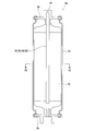
- FIG. 2 is a cross-sectional view showing the configuration of the heat pipe 10 of the first embodiment.
- FIG. 7 is a cross-sectional view showing a configuration of a heat pipe 30 of Example 2;
- FIG. 7 is a cross-sectional view showing the configuration of a heat pipe 40 of Example 3;
- FIG. 14 is a cross-sectional view showing the configuration of a heat pipe 50 of Example 4;
- FIG. 1 is a longitudinal sectional view showing a configuration of a lithium ion secondary battery provided with a heat pipe 10 according to a first embodiment.
- FIG. 5 is a schematic view showing another configuration of the lithium ion secondary battery provided with the heat pipe disclosed in the present embodiment.
- the cylinder may be entirely made of a ceramic material.
- a short circuit of the secondary battery can be suitably suppressed.
- the cylindrical body is provided at the cylindrical main body portion, at the one end of the main body portion, at the first lid portion sealing the one end, at the other end of the main body portion, and at the other end It may have the 2nd lid part which stops.
- the wick may not be provided on the inner surface of at least one of the first lid and the second lid. According to such a configuration, by not providing the wick in at least one of the lids, bonding between the lids and the body can be facilitated, and the end of the body can be suitably sealed.
- the cylinder has a first portion made of a ceramic material and a second portion made of a metal material having a thermal conductivity higher than that of the ceramic material. It may be done. Then, assuming that the dimension in the axial direction of the first portion is L1, and the dimension in the axial direction of the second portion is L2, L1> L2 may hold. According to such a configuration, the cooling capacity of the heat pipe can be further improved by the cylinder having the second portion made of the metal material having high thermal conductivity. On the other hand, even when the second portion made of metal is provided, the axial dimension L2 is shorter than the axial dimension L1 of the first portion made of the ceramic material. Therefore, even if this heat pipe is used to cool the secondary battery, it is possible to suppress a short circuit of the secondary battery.
- the first portion may be disposed at one end of the cylinder.
- the second portion may be disposed at the other end of the cylinder and may be joined to the other end of the first portion.
- a wick may be provided in at least one copy of the 1st portion.
- the first portion may be disposed at the center of the cylinder.
- the second portion is disposed at one end of the cylinder and is connected to one end of the first portion, and is disposed at the other end of the cylinder.
- a second lid portion joined to the other end of the portion.
- a wick may be provided in at least one copy of the 1st portion.
- the second portion may be disposed at the central portion of the cylinder.
- the first portion is disposed at one end of the cylinder and is connected to one end of the second portion, and is disposed at the other end of the cylinder and the second portion.
- a second lid portion joined to the other end of the portion.
- the wick may be provided on at least a portion of the first portion.
- the secondary battery provided with each said heat pipe may be equipped with a battery case and the electrode body accommodated in the battery case.
- the electrode body when the electrode body and the heat pipe are viewed in the axial direction of the heat pipe, the electrode body may be disposed around the heat pipe. According to such a configuration, the heat generated inside the electrode body can be suitably transmitted to the outside of the electrode body.
- the battery case may have a terminal surface provided with an external terminal connected to the electrode body. And one end of the heat pipe may extend toward the terminal surface. According to such a configuration, it is possible to easily dissipate the heat transmitted by the heat pipe from the terminal surface of the battery case to the outside of the battery.
- Example 1 A heat pipe 10 according to a first embodiment will be described with reference to FIG.
- the heat pipe 10 is provided with a cylindrical container (an example of a cylinder) 16 and a wick 18 provided inside the container 16.
- the container 16 is entirely made of an insulating ceramic material.
- the ceramic material for producing the container 16 for example, in addition to oxide ceramics such as alumina and zirconia, nitride ceramics having high thermal conductivity (for example, AlN, Si 3 N 4 , SiC etc.) may be used it can.
- nitride ceramics having high thermal conductivity for example, AlN, Si 3 N 4 , SiC etc.
- a composite material of a glass material and a ceramic can also be used, and furthermore, a part of the container 16 can be made of a glass material.
- the container 16 includes a cylindrical main body 12 whose both ends are open, a first cover 14 a closing one end of the main body 12, and a second cover 14 b closing the other end of the main body 12.
- the main body 12, the first cover 14a and the second cover 14b are made of the same ceramic material.
- the first lid 14a is joined to the main body 12 by a known method. A space between the first lid 14a and the main body 12 is sealed by a glass material.
- the second lid 14b is also joined to the main body 12 by a known method, and the space between the two is also sealed by the glass material.
- a fluid (working fluid) is enclosed in the container 16.
- Water, ammonia, and an organic solvent can be used as the fluid sealed in the container 16.
- the organic solvent include acetone, alcohol, fluorocarbon, glycol ethers, naphthalene, diethyl diphenyl and the like.
- the fluid one that changes from the liquid phase to the gas phase in the temperature range in which the heat pipe 10 is used is appropriately selected. Further, the pressure in the container 16 is adjusted (reduced pressure) so that the fluid changes from the liquid phase to the gas phase in the temperature range in which the heat pipe 10 is used.
- a fluid with high insulation for example, a fluorine-based liquid.
- the wick 18 has a cylindrical shape with both ends open, and is provided inside the container 16.
- the wick 18 is disposed on the inner surface of the main body 12, and no wick is disposed on the inner surface of the lids 14a and 14b.
- wicks can also be disposed on the inner surfaces of the lids 14a and 14b.
- One end of the wick 18 is in contact with the first cover 14a, and the other end of the wick 18 is in contact with the second cover 14b. Since the wick 18 is cylindrical, a space 11 is formed inside the wick 18.
- the space 11 extends in the axial direction in the container 16 from the first lid 14a to the second lid 14b.
- the wick 18 is formed with a communicating hole that develops capillary action with respect to the fluid.
- the wick 18 is made of the same ceramic material as the container 16.
- the wick 18 may be bonded to the main body 12 and integrated with each other, or the main body 12 and the wick 18 may be separately manufactured, and the wick 18 may be inserted into the main body 12.
- the wick 18 is made of a ceramic material, but may be made of a material other than the ceramic material, for example, a resin, a metal or the like.
- the usage method of the heat pipe 10 mentioned above is demonstrated.
- One end of the heat pipe 10 is disposed in the high temperature portion (heat input portion) 22, and the other end is disposed in the low temperature portion (heat radiation portion) 20.
- the fluid in the heat pipe 10 changes from the liquid phase to the gas phase in the high temperature section 22.
- the fluid changed to the gas phase travels through the space 11 inside the wick 18 to the low temperature part 20 (arrow F2 in the figure).
- the fluid moved to the low temperature unit 20 changes from the gas phase to the liquid phase in the low temperature unit 20.
- the fluid changed to the liquid phase moves to the high temperature part 22 by the capillary action of the wick 18 (arrow F1 in the figure).
- the fluid in the liquid phase that has moved to the high temperature part 22 changes to a gas phase in the high temperature part 22 and moves to the low temperature part 20 through the space 11. Thereafter, the fluid circulates in the heat pipe 10 in the same procedure. Heat transfer can be efficiently performed from the high temperature part 22 to the low temperature part 20 by circulating the inside of the heat pipe 10 while the fluid changes its phase between the liquid phase and the gas phase.
- the entire container 16 is made of an insulating ceramic material. That is, assuming that the dimension in the axial direction (X direction) of the container 16 is L, the dimension in the axial direction of the portion made of the ceramic material is also L (> L / 2). Therefore, short circuiting of the electric circuit can be suitably suppressed even if the circuit is placed in an environment where short circuiting of the electric circuit may occur.
- Example 2 A heat pipe 30 according to a second embodiment will be described with reference to FIG. In the following, differences from the first embodiment will be mainly described, and the description of the portions common to the first embodiment will be omitted.
- the heat pipe 30 includes a container 36 in which the fluid is sealed, and a wick 38 disposed inside the container 36.
- the container 36 includes a first portion 34 made of a ceramic material and a second portion 32 made of a metal material.
- the first portion 34 has a tubular shape in which one end is closed and the other end is opened, and is disposed on one end side of the container 36.
- the same material as in Example 1 can be used as the ceramic material for producing the first portion 34.
- a wick 38 is provided on the inner side surface of the first portion 34. As in the first embodiment, no wick is disposed on the inner surface of the lid portion that closes one end of the first portion 34.
- the second portion 32 has a cylindrical shape in which the other end is closed and the one end is opened, and is disposed on the other end side of the container 36.
- the second portion 32 is joined to the other end of the first portion 34 and closes the other end of the first portion 34.
- the second portion 32 and the first portion 34 are sealed.
- a metal material having a thermal conductivity higher than that of the ceramic material of the first portion 34 is used as the metal material for producing the second portion 32.
- copper (Cu), aluminum (Al), their alloys, or SUS (Stainless steel) etc. can be used.
- a wick is not provided on the inner surface of the second portion 32, but a wick may be provided on the second portion.
- the axial dimension L1 of the first portion 34 is longer than the axial dimension L2 of the second portion 32. That is, the axial dimension L1 of the first portion made of a ceramic material is longer than the axial dimension L2 of the second portion 32 made of a metal material.
- one end is disposed in the high temperature portion (heat input portion) 22, and the other end is disposed in the low temperature portion (heat dissipation portion) 20.
- the fluid in the heat pipe 10 changes from the liquid phase to the gas phase at the high temperature portion 22 (ie, the first portion 34 made of ceramic).
- the fluid changed to the gas phase travels through the space 11 inside the wick 38 to the low temperature part 20 (arrow F2 in the figure).
- the fluid moved to the low temperature part 20 changes from the gas phase to the liquid phase in the low temperature part 20 (that is, the second part 32 made of metal).
- the fluid changed to the liquid phase moves to the high temperature part 22 by the capillary action of the wick 38 (arrow F1 in the figure).
- the fluid in the liquid phase that has moved to the high temperature part 22 changes to a gas phase in the high temperature part 22 and moves to the low temperature part 20 through the space 11. Thereafter, the fluid circulates in the heat pipe 30 in the same procedure, and heat is efficiently transferred from the high temperature unit 22 to the low temperature unit 20.
- the second portion 32 made of metal is joined to the first portion 34 made of ceramic to manufacture the container 36.
- the container 36 can be easily manufactured. That is, when manufacturing the container 36, for example, after joining the first portion 34 and the second portion 32, fluid is supplied from the opening provided in the second portion 32 into the container 36, and the pressure in the container 36 is adjust. After pressure adjustment, it is only necessary to close the opening provided in the metal second portion 32. Since such a manufacturing method can be adopted, the container 36 can be manufactured more easily.
- the metal 2nd part 32 with high heat conductivity is arrange
- the heat dissipation performance from the heat pipe 30 can be improved.
- the cooling capacity of the heat pipe 30 can be improved.
- the metal 2nd part 32 is arrange
- the heat pipe 40 includes a container (42, 44, 46) in which the fluid is sealed, and a wick 48 disposed inside the container (42, 44, 46).
- the container (42, 44, 46) comprises a first portion 42 made of a ceramic material, and a first lid portion 46 and a second lid portion 44 made of a metallic material.
- the first portion 42 has an open end, and is disposed at the center of the container.
- the first lid portion 46 is joined to one end of the first portion 42, and the second lid portion 44 is joined to the other end of the first portion 42. Both ends of the first portion 42 are closed by lid portions 44 and 46.
- the first portion 42 and the first lid portion 46 are sealed, and the first portion 42 and the second lid portion 44 are sealed.
- the container (42, 44, 46) is thereby sealed.
- the fluid is enclosed in the container (42, 44, 46).
- the wick is disposed only in the first portion 42 of the container.
- the axial dimension L1 of the first portion 42 is longer than the sum of the axial dimension L22 of the first lid portion 46 and the axial dimension L21 of the second lid portion 44 (L1> L21 + L22). That is, the axial dimension L1 of the portion 42 made of a ceramic material is longer than the axial dimension (L21 + L22) of the portions 44 and 46 made of a metal material. For this reason, the short circuit of an electric circuit can be suitably suppressed by arrange
- metal portions 44 and 46 are disposed in both the high temperature portion (heat input portion) and the low temperature portion (heat radiation portion). For this reason, the heat input performance to the heat pipe 40 and the heat dissipation performance from the heat pipe 40 can be improved. As a result, the cooling capacity of the heat pipe 40 can be improved.
- Example 4 In the heat pipe 40 of Example 3 mentioned above, although the metal lid parts 44 and 46 were arrange
- the container (52, 54, 56) has lid portions 54, 52 made of a ceramic material at both ends, and is made of a metal material at its center Portion 56 is disposed. Also in this case, the sum (L12 + L11) of the dimensions in the axial direction of the lid portions 54 and 56 made of ceramic is longer than the dimension L2 in the axial direction of the metal portion 56. By adjusting the place where the metal portion 56 is disposed, a short circuit of the electric circuit can be effectively suppressed. In the heat pipe 50, wicks are disposed on all the inner side surfaces of the metal portion 56 and the lid portions 54, 56.
- the lithium ion secondary battery 70 includes a battery case 74, an electrode body 72 housed in the battery case 74, and a heat pipe 10 disposed at the center of the electrode body 72.
- the battery case 74 is cylindrical, and both ends thereof are closed by the terminal walls 76 and 78.
- the terminal walls 76 and 78 are provided with external terminals (not shown).
- the electrode body 72 includes a laminate in which a positive electrode plate, a negative electrode plate, and a separator are stacked, and the laminate is wound around an axis.
- the positive electrode plate of the electrode body 72 is electrically connected to an external terminal provided on the terminal wall 76.
- the negative electrode plate of the electrode body 72 is electrically connected to an external terminal provided on the terminal wall 78.
- the heat pipe 10 is disposed on the axis of the electrode body 72 and penetrates the center of the electrode body 72. Therefore, as shown in FIG. 6, when the electrode body 72 and the heat pipe 10 are viewed in the axial direction, the electrode body 72 is disposed around the heat pipe 10. One end of the heat pipe 10 is supported by the terminal wall 76, and the other end of the heat pipe 10 is isolated from the terminal wall 78.
- the end on the terminal wall 76 side of the heat pipe 10 is a low temperature portion (heat dissipation portion) and the portion in contact with the electrode body 72 is a high temperature portion (heat input Part).
- the heat generated from the electrode body 72 by charge and discharge is carried to the terminal wall 78 side by the heat pipe 10, and is dissipated to the outside from the terminal wall 78. Since the heat generated at the center of the electrode body 70 can be dissipated to the outside by the heat pipe 10, the lithium ion secondary battery 70 can be suitably suppressed from becoming hot. As a result, deterioration of the battery performance of the lithium ion secondary battery 70 can be suitably suppressed.
- the heat pipe 10 is made of the ceramic material in the container 16, the short circuit of the lithium ion secondary battery 70 can be prevented, and the corrosion resistance and the heat resistance can be improved. Furthermore, since the temperature rise of the lithium ion secondary battery 70 can be suppressed, the battery capacity can be improved.
- the heat pipe disclosed in this specification equips various secondary batteries Can.
- a secondary battery 80 in which a wound electrode body is formed into a flat shape.
- the battery case 82 is in the form of a rectangular parallelepiped having a rectangular cross section, and the upper surface thereof is provided with external terminals (a positive electrode terminal and a negative electrode terminal) not shown.
- one end of the heat pipe 84 is supported on the upper surface of the battery case 82, and the heat pipe 84 is disposed at the center of the electrode body (not shown).
- the heat pipe disclosed in the present specification can also be equipped with a laminated secondary battery in which the electrode body is laminated.
Landscapes
- Engineering & Computer Science (AREA)
- Manufacturing & Machinery (AREA)
- General Chemical & Material Sciences (AREA)
- Electrochemistry (AREA)
- Chemical Kinetics & Catalysis (AREA)
- Chemical & Material Sciences (AREA)
- Thermal Sciences (AREA)
- General Engineering & Computer Science (AREA)
- Mechanical Engineering (AREA)
- Physics & Mathematics (AREA)
- Life Sciences & Earth Sciences (AREA)
- Sustainable Development (AREA)
- Secondary Cells (AREA)
- Ceramic Engineering (AREA)
- Battery Mounting, Suspending (AREA)
Abstract
本明細書で開示するヒートパイプは、内部に作動流体が封入される筒体と、筒体の内部の少なくとも一部に設けられたウィックを備えている。筒体は、セラミックス材料で作製された部分を有している。そして、筒体の軸方向の寸法をLとすると、セラミックス材料で作製された部分の軸方向の寸法がL/2以上となっている。
Description
本明細書に開示する技術は、ヒートパイプに関する。詳しくは、二次電池を冷却するために好適に用いられるヒートパイプに関する。
リチウムイオン二次電池のような二次電池では、充放電時に発熱し、電池が高温になることが知られている。二次電池が高温となった状態が長く続くと、性能の劣化につながるため、二次電池を冷却するための技術が開発されている。例えば、特開2011-113895号公報に開示する二次電池では、捲回型の電極体と、その電極体の中心に配置された軸芯とを備えている。軸芯は、熱伝導率の高い金属で作製されており、電極体の軸線に沿って軸方向に伸びている。この二次電池では、充放電等によって電極体が発熱すると、その熱が軸芯を通って電極体の中心から外側に向かって伝達され、二次電池の冷却が図られる。
特開2011-113895号公報の二次電池では、電極体の軸芯が熱伝導性の高い金属で作製されているため、電極体の内部で発生した熱を効率的に外部に伝達することができる。しかしながら、電極体の中心を貫通するように金属製の軸芯が配置されるため、電極体の正極板と負極板が軸芯を介して短絡(ショート)する可能性が高くなる。本明細書は、二次電池が短絡することを抑制しながら、二次電池を効率的に冷却することができる技術を提供する。
本明細書で開示するヒートパイプは、内部に作動流体が封入される筒体と、筒体の内部の少なくとも一部に設けられたウィックと、を備えている。筒体は、セラミックス材料で作製された部分を有している。そして、筒体の軸方向の寸法をLとすると、セラミックス材料で作製された部分の軸方向の寸法がL/2以上となっている。
上記のヒートパイプは、筒体の内部で作動流体が循環し、熱を効率的に伝達することができる。また、筒体はセラミックス材料で作製された部分を有し、その部分の軸方向の寸法がL/2以上となっている。このため、上記のヒートパイプを二次電池の内部に配置すると、二次電池を効率的に冷却しながら、二次電池が短絡することを抑制することができる。
また、本明細書で開示する二次電池は、電池ケースと、電池ケース内に収容される電極体と、電池ケース内に収容され、電極体を冷却するヒートパイプを備えている。ヒートパイプは、本明細書に開示するいずれかのヒートパイプが用いられる。この二次電池では、電極体を効率的に冷却しながら、二次電池の短絡を抑制することができる。
本明細書で開示するヒートパイプでは、筒体は全体がセラミックス材料で作製されていてもよい。このようなヒートパイプを二次電池の冷却に用いると、二次電池の短絡を好適に抑制することができる。
上記のヒートパイプでは、筒体は、筒状の本体部と、本体部の一端に設けられ、その一端を封止する第1蓋部と、本体部の他端に設けられ、その他端を封止する第2蓋部と、を有していてもよい。第1蓋部と第2蓋部の少なくとも一方の内面にはウィックが設けられていなくてもよい。このような構成によると、少なくとも一方の蓋部にウィックを設けないことで、その蓋部と本体部との接合が容易となり、本体部の端部を好適に封止することができる。
また、本明細書で開示するヒートパイプでは、筒体は、セラミックス材料で作製されている第1部分と、セラミックス材料より熱伝導率の高い金属材料で作製されている第2部分と、を有していてもよい。そして、第1部分の軸方向の寸法をL1とし、第2部分の軸方向の寸法をL2とすると、L1>L2が成立してもよい。このような構成によると、筒体が熱伝導率の高い金属材料で作製された第2部分を有することで、ヒートパイプの冷却能力をより向上することができる。一方、金属で作製された第2部分を設けても、その軸方向の寸法L2はセラミックス材料で作製された第1部分の軸方向の寸法L1よりも短い。このため、このヒートパイプを二次電池の冷却に用いても、二次電池の短絡を抑制することができる。
上記のヒートパイプでは、第1部分は、筒体の一方の端部に配置されていてもよい。また、第2部分は、筒体の他方の端部に配置されており、第1部分の他方の端部に接合されていてもよい。そして、ウィックは、第1部分の少なくとも一部に設けられていてもよい。
また、上記のヒートパイプでは、第1部分は、筒体の中央部に配置されていてもよい。第2部分は、筒体の一方の端部に配置されると共に第1部分の一方の端部に接合されている第1蓋部分と、筒体の他方の端部に配置されると共に第1部分の他方の端部に接合されている第2蓋部分と、を有していてもよい。そして、ウィックは、第1部分の少なくとも一部に設けられていてもよい。
あるいは、上記のヒートパイプでは、第2部分が筒体の中央部に配置されていてもよい。第1部分は、筒体の一方の端部に配置されると共に第2部分の一方の端部に接合されている第1蓋部分と、筒体の他方の端部に配置されると共に第2部分の他方の端部に接合されている第2蓋部分と、を有していてもよい。ウィックは、第1部分の少なくとも一部に設けられていてもよい。
なお、上記の各ヒートパイプを備える二次電池は、電池ケースと、電池ケース内に収容される電極体を備えていてもよい。この場合、電極体とヒートパイプを、ヒートパイプの軸方向に沿って見ると、ヒートパイプの周囲に電極体が配置されていてもよい。このような構成によると、電極体の内部で発生する熱を電極体の外部に好適に伝達することができる。
また、上記の二次電池では、電池ケースは、電極体に接続される外部端子が設けられた端子面を有していてもよい。そして、ヒートパイプの一端は、端子面に向かって伸びていてもよい。このような構成によると、ヒートパイプで伝達される熱を、電池ケースの端子面から電池外に放熱することを容易にすることができる。
(実施例1)
図1を参照して、実施例1に係るヒートパイプ10について説明する。ヒートパイプ10は、筒状の容器(筒体の一例)16と、容器16の内部に設けられたウィック18を備えている。
図1を参照して、実施例1に係るヒートパイプ10について説明する。ヒートパイプ10は、筒状の容器(筒体の一例)16と、容器16の内部に設けられたウィック18を備えている。
容器16は、その全体が絶縁性のセラミックス材料で作製されている。容器16を作製するセラミックス材料としては、例えば、アルミナ、ジルコニアなどの酸化物系セラミックスの他、熱伝導率の高い窒化物系セラミックス(例えば、AlN,Si3N4,SiC等)を用いることができる。また、ガラス材とセラミックスの複合材料を用いることもでき、さらには、容器16の一部をガラス材によって作製することもできる。
容器16は、両端が開口した筒状の本体部12と、本体部12の一端を閉じる第1蓋部14aと、本体部12の他端を閉じる第2蓋部14bを備えている。本体部12と第1蓋部14aと第2蓋部14bは、同一のセラミックス材料によって作製されている。第1蓋部14aは、公知の方法によって本体部12に接合されている。第1蓋部14aと本体部12の間はガラス材によってシールされている。第2蓋部14bも、公知の方法によって本体部12に接合されており、両者の間もガラス材によってシールされている。
容器16内には、流体(作動流体)が封入されている。容器16内に封入される流体には、水、アンモニア、有機溶媒を用いることができる。有機溶媒の一例としては、アセトン、アルコール、フロン、グリコールエーテル類、ナフタレン、ジエチルジフェニル等が挙げられる。流体には、ヒートパイプ10が使用される温度域で液相から気相に変化するものが適宜選択される。また、ヒートパイプ10が使用される温度域で流体が液相から気相に変化するように、容器16内の圧力が調整(減圧)されている。なお、高電圧や大電流を使用する機器にヒートパイプ10が用いられる場合、絶縁性の高い流体(例えば、フッ素系液体)を用いることが好ましい。
ウィック18は、両端が開口した筒状をしており、容器16の内部に設けられている。ウィック18は、本体部12の内面に配設されており、蓋部14a,14bの内面にはウィックが配設されていない。ただし、蓋部14a,14bの内面にもウィックを配設することもできる。ウィック18の一端は第1蓋部14aに当接し、ウィック18の他端は第2蓋部14bに当接している。ウィック18が筒状であることから、ウィック18の内側に空間11が形成されている。空間11は、第1蓋部14aから第2蓋部14bまで容器16内を軸方向に伸びている。ウィック18には、流体に対して毛細管現象を発現する連通孔が形成されている。ウィック18は、容器16と同一のセラミックス材料によって作製されている。本体部12にウィック18を接合し、両者を一体化してもよいし、本体部12とウィック18を個別に制作し、本体部12にウィック18を挿入してもよい。本実施例では、ウィック18をセラミックス材料によって作製したが、セラミックス材料以外の材料、例えば、樹脂、金属等を用いて作製することもできる。
上述したヒートパイプ10の使用方法を説明する。ヒートパイプ10は、その一端が高温部(入熱部)22に配置され、その他端が低温部(放熱部)20に配置される。ヒートパイプ10内の流体は、高温部22において液相から気相に変化する。気相に変化した流体は、ウィック18の内側の空間11を通って低温部20に移動する(図内の矢印F2)。低温部20に移動した流体は、低温部20において気相から液相に変化する。液相に変化した流体は、ウィック18の毛細管現象によって高温部22に移動する(図内の矢印F1)。高温部22に移動した液相の流体は、高温部22において気相に変化し、空間11を通って低温部20に移動する。以下、同様の手順でヒートパイプ10内を流体が循環する。流体が液相と気相との間で相変化しながらヒートパイプ10内を循環することで、高温部22から低温部20に効率的に熱移動を行うことができる。
本実施例のヒートパイプ10では、容器16の全体が絶縁性のセラミックス材料によって製作されている。すなわち、容器16の軸方向(X方向)の寸法をLとすると、セラミックス材料で作製された部分の軸方向の寸法もL(>L/2)となっている。したがって、電気回路の短絡が生じ得るような環境下に配置しても、電気回路の短絡を好適に抑制することができる。
(実施例2)
図2を参照して、実施例2に係るヒートパイプ30について説明する。以下では、実施例1と相違する点を主に説明し、実施例1と共通する部分については説明を省略する。
図2を参照して、実施例2に係るヒートパイプ30について説明する。以下では、実施例1と相違する点を主に説明し、実施例1と共通する部分については説明を省略する。
ヒートパイプ30は、流体が封入される容器36と、容器36の内部に配設されたウィック38を備えている。容器36は、セラミックス材料で作製された第1部分34と、金属材料で作製された第2部分32を備えている。
第1部分34は、一端が閉じる一方で他端が開放された筒状を有しており、容器36の一端側に配置されている。第1部分34を作製するセラミックス材料は、実施例1と同様の材料を用いることができる。また、第1部分34の内側面にはウィック38が設けられている。実施例1と同様、第1部分34の一端を閉じる蓋部分の内面にはウィックが配置されていない。
第2部分32は、他端が閉じる一方で一端が開放された筒状を有しており、容器36の他端側に配置されている。第2部分32は、第1部分34の他端に接合され、第1部分34の他端を閉じている。第2部分32と第1部分34の間は封止されている。第2部分32を作製する金属材料には、第1部分34のセラミックス材料より熱伝導率の高い金属材料が用いられ、例えば、銅(Cu)、アルミニウム(Al)、それらの合金、あるいは、SUS(ステンレススチール)等を用いることができる。本実施例では、第2部分32の内面にはウィックが設けられていないが、第2部分にもウィックを設ける構成を採用することもできる。
ここで、第1部分34の軸方向の寸法L1は、第2部分32の軸方向の寸法L2より長くなっている。すなわち、セラミックス材料で作製された第1部分の軸方向の寸法L1は、金属材料で作製された第2部分32の軸方向の寸法L2より長くなっている。
上述したヒートパイプ30でも、その一端が高温部(入熱部)22に配置され、その他端が低温部(放熱部)20に配置される。ヒートパイプ10内の流体は、高温部22(すなわち、セラミックス製の第1部分34)において液相から気相に変化する。気相に変化した流体は、ウィック38の内側の空間11を通って低温部20に移動する(図内の矢印F2)。低温部20に移動した流体は、低温部20(すなわち、金属製の第2部分32)において気相から液相に変化する。液相に変化した流体は、ウィック38の毛細管現象によって高温部22に移動する(図内の矢印F1)。高温部22に移動した液相の流体は、高温部22において気相に変化し、空間11を通って低温部20に移動する。以下、同様の手順でヒートパイプ30内を流体が循環し、高温部22から低温部20に効率的に熱移動が行われる。
本実施例のヒートパイプ30では、セラミックス製の第1部分34に金属製の第2部分32を接合して、容器36を製作している。このため、容器36の製作を容易に行うことができる。すなわち、容器36を製作する際は、例えば、第1部分34と第2部分32を接合した後に、第2部分32に設けた開口から容器36内に流体を供給し、容器36内の圧力を調整する。圧力調整後は、金属製の第2部分32に設けた開口を閉じるだけでよい。このような製造方法が採用可能となるため、容器36の製造をより簡易に行うことができる。
また、ヒートパイプ30では、低温部20に熱伝導率の高い金属製の第2部分32が配置されるため、ヒートパイプ30からの放熱性能を向上することができる。その結果、ヒートパイプ30による冷却能力を向上することができる。なお、容器36に金属製の第2部分32が配置されるが、第2部分32は第1部分に比較して軸方向の寸法L2が短くされる。このため、電気回路の短絡が生じ得るような環境下に配置しても、電気回路の短絡を好適に抑制することができる。
(実施例3)
図3を参照して、実施例3に係るヒートパイプ40について説明する。ヒートパイプ40は、流体が封入される容器(42,44,46)と、容器(42,44,46)の内部に配設されたウィック48を備えている。容器(42,44,46)は、セラミックス材料で作製された第1部分42と、金属材料で作製された第1蓋部分46,第2蓋部分44を備えている。
図3を参照して、実施例3に係るヒートパイプ40について説明する。ヒートパイプ40は、流体が封入される容器(42,44,46)と、容器(42,44,46)の内部に配設されたウィック48を備えている。容器(42,44,46)は、セラミックス材料で作製された第1部分42と、金属材料で作製された第1蓋部分46,第2蓋部分44を備えている。
第1部分42は、両端が開放された形状を有しており、容器の中央に配されている。第1蓋部分46は、第1部分42の一端に接合されており、第2蓋部分44は第1部分42の他端に接合されている。第1部分42の両端は、蓋部分44,46によって閉じられている。第1部分42と第1蓋部分46との間はシールされており、第1部分42と第2蓋部分44の間はシールされている。これによって、容器(42,44,46)が密閉されている。なお、容器(42,44,46)内には流体が封入されている。また、容器の第1部分42にのみウィックが配設されている。
ここで、第1部分42の軸方向の寸法L1は、第1蓋部分46の軸方向の寸法L22と第2蓋部分44の軸方向の寸法L21との和よりも長くなっている(L1>L21+L22)。すなわち、セラミックス材料で作製された部分42の軸方向の寸法L1は、金属材料で作製された部分44,46の軸方向の寸法(L21+L22)より長くなっている。このため、金属材料で作製された部分44,46を両端部に限定的に配置することで、電気回路の短絡を好適に抑制することができる。
本実施例のヒートパイプ40では、高温部(入熱部)と低温部(放熱部)の両者に、金属製の部分44,46が配置される。このため、ヒートパイプ40への入熱性能と、ヒートパイプ40からの放熱性能を向上することができる。その結果、ヒートパイプ40の冷却能力を向上することができる。
(実施例4)
上述した実施例3のヒートパイプ40では、容器の両端に金属製の蓋部分44,46を配置したが、このような例に限られない。図4に示す実施例4のヒートパイプ50のように、容器(52,54,56)は、両端にセラミックス材料で作製された蓋部分54,52を配置し、その中央に金属材料で作製された部分56を配置している。この場合でも、セラミックス製の蓋部分54,56の軸方向の寸法の和(L12+L11)は、金属製の部分56の軸方向の寸法L2より長くなっている。金属製の部分56を配置する場所を調整することで、電気回路の短絡を効果的に抑制することができる。なお、ヒートパイプ50では、金属製の部分56と蓋部分54,56の全ての内側面にウィックが配置されている。
上述した実施例3のヒートパイプ40では、容器の両端に金属製の蓋部分44,46を配置したが、このような例に限られない。図4に示す実施例4のヒートパイプ50のように、容器(52,54,56)は、両端にセラミックス材料で作製された蓋部分54,52を配置し、その中央に金属材料で作製された部分56を配置している。この場合でも、セラミックス製の蓋部分54,56の軸方向の寸法の和(L12+L11)は、金属製の部分56の軸方向の寸法L2より長くなっている。金属製の部分56を配置する場所を調整することで、電気回路の短絡を効果的に抑制することができる。なお、ヒートパイプ50では、金属製の部分56と蓋部分54,56の全ての内側面にウィックが配置されている。
(リチウムイオン二次電池)
ここで、上述したヒートパイプ10をリチウムイオン二次電池に装備した一例について、図5,6を参照して説明する。なお、この例ではリチウムイオン二次電池にヒートパイプ10を装備した例であったが、他のヒートパイプ30,40,50についても同様に装備することができる。
ここで、上述したヒートパイプ10をリチウムイオン二次電池に装備した一例について、図5,6を参照して説明する。なお、この例ではリチウムイオン二次電池にヒートパイプ10を装備した例であったが、他のヒートパイプ30,40,50についても同様に装備することができる。
図5に示すように、リチウムイオン二次電池70は、電池ケース74と、電池ケース74内に収容される電極体72と、電極体72の中央に配置されるヒートパイプ10を備えている。電池ケース74は、円筒状であり、その両端が端子壁76,78で閉じられている。端子壁76,78には外部端子(図示省略)が設けられている。
電極体72は、正極板と負極板とセパレータとを積層した積層体を備えており、この積層体は軸線周りに捲回されている。電極体72の正極板は、端子壁76に設けられた外部端子に電気的に接続されている。電極体72の負極板は、端子壁78に設けられた外部端子に電気的に接続されている。
ヒートパイプ10は、電極体72の軸線上に配置されており、電極体72の中央を貫通している。このため、図6に示すように、電極体72とヒートパイプ10を軸方向に沿って見ると、ヒートパイプ10の周囲に電極体72が配置されていることになる。ヒートパイプ10の一端は端子壁76に支持され、ヒートパイプ10の他端は端子壁78から隔離されている。
上述の説明から明らかなように、リチウムイオン二次電池70では、ヒートパイプ10の端子壁76側の端部が低温部(放熱部)となり、電極体72と接触する部分が高温部(入熱部)となる。充放電によって電極体72から発生する熱は、ヒートパイプ10によって端子壁78側に運ばれ、端子壁78から外部に放熱される。電極体70の中央で発生する熱をヒートパイプ10によって外部に放熱できるため、リチウムイオン二次電池70が高温になることを好適に抑制することができる。その結果、リチウムイオン二次電池70の電池性能の劣化を好適に抑制することができる。
また、ヒートパイプ10は、容器16がセラミックス材料で制作されているため、リチウムイオン二次電池70の短絡を防止し、また、耐食性及び耐熱性を向上することができる。さらに、リチウムイオン二次電池70の温度上昇が抑制できるため、電池容量を向上することができる。
なお、上述した実施例の二次電池は、電極体を円筒状に捲回したリチウムイオン二次電池であったが、本明細書に開示のヒートパイプは、種々の二次電池に装備することができる。例えば、図7に示すように、捲回型の電極体を扁平状に成形した二次電池80に装備することができる。電池ケース82は、断面が長方形の直方体状であり、その上面には図示しない外部端子(正極端子と負極端子)が設けられている。この場合でも、ヒートパイプ84は、電池ケース82の上面に一端が支持され、図示しない電極体の中心に配置される。さらに、本明細書に開示のヒートパイプは、電極体を積層した積層型の二次電池にも装備することができる。
以上、本発明の実施形態について詳細に説明したが、これらは例示に過ぎず、請求の範囲を限定するものではない。請求の範囲に記載の技術には、以上に例示した具体例を様々に変形、変更したものが含まれる。また、本明細書または図面に説明した技術要素は、単独であるいは各種の組合せによって技術的有用性を発揮するものであり、出願時請求項記載の組合せに限定されるものではない。また、本明細書または図面に例示した技術は複数目的を同時に達成するものであり、そのうちの一つの目的を達成すること自体で技術的有用性を持つものである。
Claims (10)
- ヒートパイプであって、
内部に作動流体が封入される筒体と、
前記筒体の内部の少なくとも一部に設けられたウィックと、を備えており、
前記筒体は、セラミックス材料で作製された部分を有しており、
前記筒体の軸方向の寸法をLとすると、前記セラミックス材料で作製された部分の軸方向の寸法がL/2以上となっている、ヒートパイプ。 - 前記筒体は、全体が前記セラミックス材料で作製されている、請求項1に記載のヒートパイプ。
- 前記筒体は、
筒状の本体部と、
前記本体部の一端に設けられ、前記一端を封止する第1蓋部と、
前記本体部の他端に設けられ、前記他端を封止する第2蓋部と、を有しており、
前記第1蓋部と前記第2蓋部の少なくとも一方の内面にはウィックが設けられていない、請求項2に記載のヒートパイプ。 - 前記筒体は、前記セラミックス材料で作製されている第1部分と、前記セラミックス材料より熱伝導率の高い金属材料で作製されている第2部分と、を有しており、
前記第1部分の軸方向の寸法をL1とし、前記第2部分の軸方向の寸法をL2とすると、L1>L2が成立する、請求項1に記載のヒートパイプ。 - 前記第1部分は、前記筒体の一方の端部に配置されており、
前記第2部分は、前記筒体の他方の端部に配置されており、前記第1部分の他方の端部に接合されており、
前記ウィックは、前記第1部分の少なくとも一部に設けられている、請求項4に記載のヒートパイプ。 - 前記第1部分は、前記筒体の中央部に配置されており、
前記第2部分は、前記筒体の一方の端部に配置されると共に前記第1部分の一方の端部に接合されている第1蓋部分と、前記筒体の他方の端部に配置されると共に前記第1部分の他方の端部に接合されている第2蓋部分と、を有しており、
前記ウィックは、前記第1部分の少なくとも一部に設けられている、請求項4に記載のヒートパイプ。 - 前記第2部分は、前記筒体の中央部に配置されており、
前記第1部分は、前記筒体の一方の端部に配置されると共に前記第2部分の一方の端部に接合されている第1蓋部分と、前記筒体の他方の端部に配置されると共に前記第2部分の他方の端部に接合されている第2蓋部分と、を有しており、
前記ウィックは、前記第1部分の少なくとも一部に設けられている、請求項4に記載のヒートパイプ。 - 電池ケースと、
前記電池ケース内に収容される電極体と、
前記電池ケース内に収容され、前記電極体を冷却する請求項1~7のいずれか1項に記載のヒートパイプと、
を備える、二次電池。 - 前記電極体と前記ヒートパイプを、前記ヒートパイプの軸方向に沿って見ると、前記ヒートパイプの周囲に前記電極体が配置されている、請求項8に記載の二次電池。
- 前記電池ケースは、前記電極体に接続される外部端子が設けられた端子面を有しており、
前記ヒートパイプの一端は、前記端子面に向かって伸びている、請求項8又は9に記載の二次電池。
Priority Applications (4)
| Application Number | Priority Date | Filing Date | Title |
|---|---|---|---|
| JP2019544514A JP6870100B2 (ja) | 2017-09-29 | 2018-09-07 | ヒートパイプ及びヒートパイプを備えた二次電池 |
| DE112018004363.0T DE112018004363T5 (de) | 2017-09-29 | 2018-09-07 | Heatpipe und sekundärbatterie mit heatpipe |
| CN201880053383.5A CN111033164A (zh) | 2017-09-29 | 2018-09-07 | 热管及具备热管的二次电池 |
| US16/823,922 US20200220239A1 (en) | 2017-09-29 | 2020-03-19 | Heat pipe and secondary battery comprising heat pipe |
Applications Claiming Priority (2)
| Application Number | Priority Date | Filing Date | Title |
|---|---|---|---|
| JP2017191442 | 2017-09-29 | ||
| JP2017-191442 | 2017-09-29 |
Related Child Applications (1)
| Application Number | Title | Priority Date | Filing Date |
|---|---|---|---|
| US16/823,922 Continuation US20200220239A1 (en) | 2017-09-29 | 2020-03-19 | Heat pipe and secondary battery comprising heat pipe |
Publications (1)
| Publication Number | Publication Date |
|---|---|
| WO2019065166A1 true WO2019065166A1 (ja) | 2019-04-04 |
Family
ID=65903522
Family Applications (1)
| Application Number | Title | Priority Date | Filing Date |
|---|---|---|---|
| PCT/JP2018/033320 Ceased WO2019065166A1 (ja) | 2017-09-29 | 2018-09-07 | ヒートパイプ及びヒートパイプを備えた二次電池 |
Country Status (5)
| Country | Link |
|---|---|
| US (1) | US20200220239A1 (ja) |
| JP (1) | JP6870100B2 (ja) |
| CN (1) | CN111033164A (ja) |
| DE (1) | DE112018004363T5 (ja) |
| WO (1) | WO2019065166A1 (ja) |
Cited By (2)
| Publication number | Priority date | Publication date | Assignee | Title |
|---|---|---|---|---|
| JP2022110792A (ja) * | 2021-01-19 | 2022-07-29 | 株式会社デンソー | 沸騰冷却装置およびその製造方法 |
| JP7547224B2 (ja) | 2021-01-20 | 2024-09-09 | 古河電気工業株式会社 | ヒートパイプ |
Families Citing this family (2)
| Publication number | Priority date | Publication date | Assignee | Title |
|---|---|---|---|---|
| CN111540977B (zh) * | 2020-04-21 | 2022-04-22 | 华南理工大学 | 一种动力电池液冷型热管理系统及吹胀型铝质均热板 |
| CN113410588A (zh) * | 2021-06-18 | 2021-09-17 | 陕西奥林波斯电力能源有限责任公司 | 一种极柱和使用该极柱的大容量电池 |
Citations (8)
| Publication number | Priority date | Publication date | Assignee | Title |
|---|---|---|---|---|
| JPS52166866U (ja) * | 1976-06-11 | 1977-12-17 | ||
| JPS5787588A (en) * | 1980-11-19 | 1982-06-01 | Hitachi Ltd | Heat pipe |
| JPS57127178U (ja) * | 1981-02-02 | 1982-08-07 | ||
| JPH02148662A (ja) * | 1988-11-30 | 1990-06-07 | Fujikura Ltd | 二次電池 |
| JPH0749188A (ja) * | 1994-07-27 | 1995-02-21 | Nippon Alum Co Ltd | 電気絶縁型ヒートパイプの製造方法 |
| JP2000260474A (ja) * | 1999-03-05 | 2000-09-22 | Hitachi Ltd | リチウム2次電池 |
| JP2001012880A (ja) * | 1999-06-29 | 2001-01-19 | Ngk Spark Plug Co Ltd | 絶縁型ヒートパイプの製造方法 |
| JP2008122024A (ja) * | 2006-11-15 | 2008-05-29 | Sumitomo Electric Ind Ltd | ヒートパイプ、ヒートパイプモジュール及びヒートパイプの製造方法 |
Family Cites Families (2)
| Publication number | Priority date | Publication date | Assignee | Title |
|---|---|---|---|---|
| CN86210768U (zh) * | 1986-12-16 | 1987-12-05 | 山东省新材料研究所 | 黑色陶瓷热管 |
| CN101975524A (zh) * | 2010-10-24 | 2011-02-16 | 西南交通大学 | 能够避免热回流的热棒 |
-
2018
- 2018-09-07 CN CN201880053383.5A patent/CN111033164A/zh active Pending
- 2018-09-07 DE DE112018004363.0T patent/DE112018004363T5/de not_active Withdrawn
- 2018-09-07 WO PCT/JP2018/033320 patent/WO2019065166A1/ja not_active Ceased
- 2018-09-07 JP JP2019544514A patent/JP6870100B2/ja not_active Expired - Fee Related
-
2020
- 2020-03-19 US US16/823,922 patent/US20200220239A1/en not_active Abandoned
Patent Citations (8)
| Publication number | Priority date | Publication date | Assignee | Title |
|---|---|---|---|---|
| JPS52166866U (ja) * | 1976-06-11 | 1977-12-17 | ||
| JPS5787588A (en) * | 1980-11-19 | 1982-06-01 | Hitachi Ltd | Heat pipe |
| JPS57127178U (ja) * | 1981-02-02 | 1982-08-07 | ||
| JPH02148662A (ja) * | 1988-11-30 | 1990-06-07 | Fujikura Ltd | 二次電池 |
| JPH0749188A (ja) * | 1994-07-27 | 1995-02-21 | Nippon Alum Co Ltd | 電気絶縁型ヒートパイプの製造方法 |
| JP2000260474A (ja) * | 1999-03-05 | 2000-09-22 | Hitachi Ltd | リチウム2次電池 |
| JP2001012880A (ja) * | 1999-06-29 | 2001-01-19 | Ngk Spark Plug Co Ltd | 絶縁型ヒートパイプの製造方法 |
| JP2008122024A (ja) * | 2006-11-15 | 2008-05-29 | Sumitomo Electric Ind Ltd | ヒートパイプ、ヒートパイプモジュール及びヒートパイプの製造方法 |
Cited By (2)
| Publication number | Priority date | Publication date | Assignee | Title |
|---|---|---|---|---|
| JP2022110792A (ja) * | 2021-01-19 | 2022-07-29 | 株式会社デンソー | 沸騰冷却装置およびその製造方法 |
| JP7547224B2 (ja) | 2021-01-20 | 2024-09-09 | 古河電気工業株式会社 | ヒートパイプ |
Also Published As
| Publication number | Publication date |
|---|---|
| CN111033164A (zh) | 2020-04-17 |
| US20200220239A1 (en) | 2020-07-09 |
| DE112018004363T5 (de) | 2020-09-24 |
| JP6870100B2 (ja) | 2021-05-12 |
| JPWO2019065166A1 (ja) | 2020-11-05 |
Similar Documents
| Publication | Publication Date | Title |
|---|---|---|
| WO2019065166A1 (ja) | ヒートパイプ及びヒートパイプを備えた二次電池 | |
| JP5800989B2 (ja) | ヒートパイプを有し電気エネルギーを蓄積するための蓄積ユニット | |
| US9466823B2 (en) | Rechargeable battery | |
| US6661133B2 (en) | Rotor cooling arrangement | |
| JP6425638B2 (ja) | 高容量リレー用パイプリード付き気密端子およびその気密端子を用いたリレー用接点装置 | |
| US10651520B2 (en) | Battery | |
| CN101300727B (zh) | 驱动系统 | |
| CN110660563A (zh) | 磁性组件及电源模块 | |
| US20200075239A1 (en) | Capacitive block including a heat sink | |
| WO2013147240A1 (ja) | 流路部材およびこれを用いた熱交換器ならびに半導体装置 | |
| JP6272140B2 (ja) | 半導体素子収納用パッケージ、およびこれを備えた半導体装置 | |
| JP2018186272A (ja) | 高圧端子の冷却構造 | |
| JP2012186114A (ja) | 二次電池および二次電池モジュール | |
| JP2018503217A (ja) | Eモビリティ分野における熱管理 | |
| US11916209B2 (en) | Power supply device | |
| WO2014064945A1 (ja) | 熱電変換モジュール | |
| US3989979A (en) | Magnetron employing a permanent magnet formed of a manganese-aluminum-carbon system alloy | |
| US20140307360A1 (en) | Immersion cooled capacitor for power electronics convertor | |
| US8232855B2 (en) | High energy density inductor | |
| JP2019009090A (ja) | 吸熱体付き導体及び電池パック | |
| US10847285B1 (en) | Electric wire with cooling function | |
| US4574261A (en) | Bakeable electromagnets | |
| CN114258736A (zh) | 电子系统和包括这种电子系统的电压转换器 | |
| JP7617524B2 (ja) | 継電構造体 | |
| CN211858626U (zh) | 冷却板 |
Legal Events
| Date | Code | Title | Description |
|---|---|---|---|
| 121 | Ep: the epo has been informed by wipo that ep was designated in this application |
Ref document number: 18860714 Country of ref document: EP Kind code of ref document: A1 |
|
| ENP | Entry into the national phase |
Ref document number: 2019544514 Country of ref document: JP Kind code of ref document: A |
|
| 122 | Ep: pct application non-entry in european phase |
Ref document number: 18860714 Country of ref document: EP Kind code of ref document: A1 |