WO2019065114A1 - 油井管用マルテンサイト系ステンレス継目無鋼管およびその製造方法 - Google Patents
油井管用マルテンサイト系ステンレス継目無鋼管およびその製造方法 Download PDFInfo
- Publication number
- WO2019065114A1 WO2019065114A1 PCT/JP2018/032684 JP2018032684W WO2019065114A1 WO 2019065114 A1 WO2019065114 A1 WO 2019065114A1 JP 2018032684 W JP2018032684 W JP 2018032684W WO 2019065114 A1 WO2019065114 A1 WO 2019065114A1
- Authority
- WO
- WIPO (PCT)
- Prior art keywords
- less
- steel pipe
- martensitic stainless
- oil well
- seamless steel
- Prior art date
Links
Classifications
-
- C—CHEMISTRY; METALLURGY
- C22—METALLURGY; FERROUS OR NON-FERROUS ALLOYS; TREATMENT OF ALLOYS OR NON-FERROUS METALS
- C22C—ALLOYS
- C22C38/00—Ferrous alloys, e.g. steel alloys
- C22C38/02—Ferrous alloys, e.g. steel alloys containing silicon
-
- C—CHEMISTRY; METALLURGY
- C21—METALLURGY OF IRON
- C21D—MODIFYING THE PHYSICAL STRUCTURE OF FERROUS METALS; GENERAL DEVICES FOR HEAT TREATMENT OF FERROUS OR NON-FERROUS METALS OR ALLOYS; MAKING METAL MALLEABLE, e.g. BY DECARBURISATION OR TEMPERING
- C21D9/00—Heat treatment, e.g. annealing, hardening, quenching or tempering, adapted for particular articles; Furnaces therefor
- C21D9/08—Heat treatment, e.g. annealing, hardening, quenching or tempering, adapted for particular articles; Furnaces therefor for tubular bodies or pipes
- C21D9/14—Heat treatment, e.g. annealing, hardening, quenching or tempering, adapted for particular articles; Furnaces therefor for tubular bodies or pipes wear-resistant or pressure-resistant pipes
-
- C—CHEMISTRY; METALLURGY
- C21—METALLURGY OF IRON
- C21D—MODIFYING THE PHYSICAL STRUCTURE OF FERROUS METALS; GENERAL DEVICES FOR HEAT TREATMENT OF FERROUS OR NON-FERROUS METALS OR ALLOYS; MAKING METAL MALLEABLE, e.g. BY DECARBURISATION OR TEMPERING
- C21D1/00—General methods or devices for heat treatment, e.g. annealing, hardening, quenching or tempering
- C21D1/18—Hardening; Quenching with or without subsequent tempering
- C21D1/19—Hardening; Quenching with or without subsequent tempering by interrupted quenching
- C21D1/22—Martempering
-
- C—CHEMISTRY; METALLURGY
- C21—METALLURGY OF IRON
- C21D—MODIFYING THE PHYSICAL STRUCTURE OF FERROUS METALS; GENERAL DEVICES FOR HEAT TREATMENT OF FERROUS OR NON-FERROUS METALS OR ALLOYS; MAKING METAL MALLEABLE, e.g. BY DECARBURISATION OR TEMPERING
- C21D6/00—Heat treatment of ferrous alloys
- C21D6/004—Heat treatment of ferrous alloys containing Cr and Ni
-
- C—CHEMISTRY; METALLURGY
- C21—METALLURGY OF IRON
- C21D—MODIFYING THE PHYSICAL STRUCTURE OF FERROUS METALS; GENERAL DEVICES FOR HEAT TREATMENT OF FERROUS OR NON-FERROUS METALS OR ALLOYS; MAKING METAL MALLEABLE, e.g. BY DECARBURISATION OR TEMPERING
- C21D6/00—Heat treatment of ferrous alloys
- C21D6/005—Heat treatment of ferrous alloys containing Mn
-
- C—CHEMISTRY; METALLURGY
- C21—METALLURGY OF IRON
- C21D—MODIFYING THE PHYSICAL STRUCTURE OF FERROUS METALS; GENERAL DEVICES FOR HEAT TREATMENT OF FERROUS OR NON-FERROUS METALS OR ALLOYS; MAKING METAL MALLEABLE, e.g. BY DECARBURISATION OR TEMPERING
- C21D6/00—Heat treatment of ferrous alloys
- C21D6/008—Heat treatment of ferrous alloys containing Si
-
- C—CHEMISTRY; METALLURGY
- C21—METALLURGY OF IRON
- C21D—MODIFYING THE PHYSICAL STRUCTURE OF FERROUS METALS; GENERAL DEVICES FOR HEAT TREATMENT OF FERROUS OR NON-FERROUS METALS OR ALLOYS; MAKING METAL MALLEABLE, e.g. BY DECARBURISATION OR TEMPERING
- C21D8/00—Modifying the physical properties by deformation combined with, or followed by, heat treatment
- C21D8/10—Modifying the physical properties by deformation combined with, or followed by, heat treatment during manufacturing of tubular bodies
- C21D8/105—Modifying the physical properties by deformation combined with, or followed by, heat treatment during manufacturing of tubular bodies of ferrous alloys
-
- C—CHEMISTRY; METALLURGY
- C21—METALLURGY OF IRON
- C21D—MODIFYING THE PHYSICAL STRUCTURE OF FERROUS METALS; GENERAL DEVICES FOR HEAT TREATMENT OF FERROUS OR NON-FERROUS METALS OR ALLOYS; MAKING METAL MALLEABLE, e.g. BY DECARBURISATION OR TEMPERING
- C21D9/00—Heat treatment, e.g. annealing, hardening, quenching or tempering, adapted for particular articles; Furnaces therefor
- C21D9/08—Heat treatment, e.g. annealing, hardening, quenching or tempering, adapted for particular articles; Furnaces therefor for tubular bodies or pipes
- C21D9/085—Cooling or quenching
-
- C—CHEMISTRY; METALLURGY
- C22—METALLURGY; FERROUS OR NON-FERROUS ALLOYS; TREATMENT OF ALLOYS OR NON-FERROUS METALS
- C22C—ALLOYS
- C22C38/00—Ferrous alloys, e.g. steel alloys
-
- C—CHEMISTRY; METALLURGY
- C22—METALLURGY; FERROUS OR NON-FERROUS ALLOYS; TREATMENT OF ALLOYS OR NON-FERROUS METALS
- C22C—ALLOYS
- C22C38/00—Ferrous alloys, e.g. steel alloys
- C22C38/001—Ferrous alloys, e.g. steel alloys containing N
-
- C—CHEMISTRY; METALLURGY
- C22—METALLURGY; FERROUS OR NON-FERROUS ALLOYS; TREATMENT OF ALLOYS OR NON-FERROUS METALS
- C22C—ALLOYS
- C22C38/00—Ferrous alloys, e.g. steel alloys
- C22C38/002—Ferrous alloys, e.g. steel alloys containing In, Mg, or other elements not provided for in one single group C22C38/001 - C22C38/60
-
- C—CHEMISTRY; METALLURGY
- C22—METALLURGY; FERROUS OR NON-FERROUS ALLOYS; TREATMENT OF ALLOYS OR NON-FERROUS METALS
- C22C—ALLOYS
- C22C38/00—Ferrous alloys, e.g. steel alloys
- C22C38/004—Very low carbon steels, i.e. having a carbon content of less than 0,01%
-
- C—CHEMISTRY; METALLURGY
- C22—METALLURGY; FERROUS OR NON-FERROUS ALLOYS; TREATMENT OF ALLOYS OR NON-FERROUS METALS
- C22C—ALLOYS
- C22C38/00—Ferrous alloys, e.g. steel alloys
- C22C38/005—Ferrous alloys, e.g. steel alloys containing rare earths, i.e. Sc, Y, Lanthanides
-
- C—CHEMISTRY; METALLURGY
- C22—METALLURGY; FERROUS OR NON-FERROUS ALLOYS; TREATMENT OF ALLOYS OR NON-FERROUS METALS
- C22C—ALLOYS
- C22C38/00—Ferrous alloys, e.g. steel alloys
- C22C38/04—Ferrous alloys, e.g. steel alloys containing manganese
-
- C—CHEMISTRY; METALLURGY
- C22—METALLURGY; FERROUS OR NON-FERROUS ALLOYS; TREATMENT OF ALLOYS OR NON-FERROUS METALS
- C22C—ALLOYS
- C22C38/00—Ferrous alloys, e.g. steel alloys
- C22C38/06—Ferrous alloys, e.g. steel alloys containing aluminium
-
- C—CHEMISTRY; METALLURGY
- C22—METALLURGY; FERROUS OR NON-FERROUS ALLOYS; TREATMENT OF ALLOYS OR NON-FERROUS METALS
- C22C—ALLOYS
- C22C38/00—Ferrous alloys, e.g. steel alloys
- C22C38/18—Ferrous alloys, e.g. steel alloys containing chromium
- C22C38/40—Ferrous alloys, e.g. steel alloys containing chromium with nickel
- C22C38/42—Ferrous alloys, e.g. steel alloys containing chromium with nickel with copper
-
- C—CHEMISTRY; METALLURGY
- C22—METALLURGY; FERROUS OR NON-FERROUS ALLOYS; TREATMENT OF ALLOYS OR NON-FERROUS METALS
- C22C—ALLOYS
- C22C38/00—Ferrous alloys, e.g. steel alloys
- C22C38/18—Ferrous alloys, e.g. steel alloys containing chromium
- C22C38/40—Ferrous alloys, e.g. steel alloys containing chromium with nickel
- C22C38/44—Ferrous alloys, e.g. steel alloys containing chromium with nickel with molybdenum or tungsten
-
- C—CHEMISTRY; METALLURGY
- C22—METALLURGY; FERROUS OR NON-FERROUS ALLOYS; TREATMENT OF ALLOYS OR NON-FERROUS METALS
- C22C—ALLOYS
- C22C38/00—Ferrous alloys, e.g. steel alloys
- C22C38/18—Ferrous alloys, e.g. steel alloys containing chromium
- C22C38/40—Ferrous alloys, e.g. steel alloys containing chromium with nickel
- C22C38/46—Ferrous alloys, e.g. steel alloys containing chromium with nickel with vanadium
-
- C—CHEMISTRY; METALLURGY
- C22—METALLURGY; FERROUS OR NON-FERROUS ALLOYS; TREATMENT OF ALLOYS OR NON-FERROUS METALS
- C22C—ALLOYS
- C22C38/00—Ferrous alloys, e.g. steel alloys
- C22C38/18—Ferrous alloys, e.g. steel alloys containing chromium
- C22C38/40—Ferrous alloys, e.g. steel alloys containing chromium with nickel
- C22C38/48—Ferrous alloys, e.g. steel alloys containing chromium with nickel with niobium or tantalum
-
- C—CHEMISTRY; METALLURGY
- C22—METALLURGY; FERROUS OR NON-FERROUS ALLOYS; TREATMENT OF ALLOYS OR NON-FERROUS METALS
- C22C—ALLOYS
- C22C38/00—Ferrous alloys, e.g. steel alloys
- C22C38/18—Ferrous alloys, e.g. steel alloys containing chromium
- C22C38/40—Ferrous alloys, e.g. steel alloys containing chromium with nickel
- C22C38/50—Ferrous alloys, e.g. steel alloys containing chromium with nickel with titanium or zirconium
-
- C—CHEMISTRY; METALLURGY
- C22—METALLURGY; FERROUS OR NON-FERROUS ALLOYS; TREATMENT OF ALLOYS OR NON-FERROUS METALS
- C22C—ALLOYS
- C22C38/00—Ferrous alloys, e.g. steel alloys
- C22C38/18—Ferrous alloys, e.g. steel alloys containing chromium
- C22C38/40—Ferrous alloys, e.g. steel alloys containing chromium with nickel
- C22C38/52—Ferrous alloys, e.g. steel alloys containing chromium with nickel with cobalt
-
- C—CHEMISTRY; METALLURGY
- C22—METALLURGY; FERROUS OR NON-FERROUS ALLOYS; TREATMENT OF ALLOYS OR NON-FERROUS METALS
- C22C—ALLOYS
- C22C38/00—Ferrous alloys, e.g. steel alloys
- C22C38/18—Ferrous alloys, e.g. steel alloys containing chromium
- C22C38/40—Ferrous alloys, e.g. steel alloys containing chromium with nickel
- C22C38/54—Ferrous alloys, e.g. steel alloys containing chromium with nickel with boron
-
- C—CHEMISTRY; METALLURGY
- C21—METALLURGY OF IRON
- C21D—MODIFYING THE PHYSICAL STRUCTURE OF FERROUS METALS; GENERAL DEVICES FOR HEAT TREATMENT OF FERROUS OR NON-FERROUS METALS OR ALLOYS; MAKING METAL MALLEABLE, e.g. BY DECARBURISATION OR TEMPERING
- C21D2211/00—Microstructure comprising significant phases
- C21D2211/008—Martensite
Definitions
- the present invention relates to a martensitic stainless steel seamless steel pipe for oil well used for oil wells and gas wells of crude oil or natural gas (hereinafter simply referred to as oil wells) and a method for producing the same.
- the present invention relates to improvement of sulfide stress corrosion cracking resistance (SSC resistance) in an environment containing hydrogen sulfide (H 2 S).
- Patent Document 1 C is significantly reduced compared to the prior art, containing 13% Cr steel as a basic composition, Ni, Mo and Cu are contained, Cr + 2Ni + 1.1Mo + 0.7Cu ⁇ 32.5 is satisfied, and Nb: 0.20% or less , V: 0.20% or less of which one or two kinds are contained so as to satisfy the condition of Nb + V% 0.05%, yield stress: high strength of 965 MPa or more, and Charpy at -40 ° C It has high toughness of 50 J or more, and it can maintain good corrosion resistance.
- Patent Document 2 describes a component system 13% Cr-based martensitic stainless steel pipe containing an extremely low C amount of 0.015% or less and Ti of 0.03% or more, and a high strength of yield stress 95 ksi class, It has low hardness of less than 27 in HRC, and has excellent SSC resistance.
- Patent Document 3 describes a martensitic stainless steel satisfying 6.0 ⁇ Ti / C ⁇ 10.1 because Ti / C has a correlation with a value obtained by subtracting yield stress from tensile stress. According to the technology described above, the value obtained by subtracting the yield stress from the tensile stress is 20.7 MPa or more, and the variation in hardness that reduces the SSC resistance can be suppressed.
- the amount of Mo in the steel is defined as Mo2.32.3 ⁇ 0.89 Si + 32.2 C, and the metal structure is mainly tempered martensite, carbide precipitated during tempering, and Laves precipitated finely during tempering.
- a martensitic stainless steel composed of intermetallic compounds such as phase and ⁇ phase is described. According to the technology described above, it is said that the 0.2% proof stress of the steel becomes high strength of 860 MPa or more, and can have excellent carbon dioxide gas corrosion resistance and sulfide stress corrosion cracking resistance.
- JP 2007-332442 A JP, 2010-242163, A International Publication 2008/023702 International Publication 2004/057050
- Patent Document 2 it is considered that sulfide stress cracking resistance can be maintained under a condition that a stress of 655 MPa is applied under an atmosphere adjusted to pH: 3.5 with 5% NaCl aqueous solution (H 2 S: 0.10 bar).
- Patent Document 3 describes an aqueous solution of 20% NaCl aqueous solution (H 2 S: 0.03 bar, CO 2 bal.) Adjusted to pH: 4.5
- Patent Document 4 an aqueous 25% NaCl solution (H 2 S: 0.03
- the steel is considered to have resistance to sulfide stress cracking under an atmosphere adjusted to pH: 4.0 bar, CO 2 bal).
- sulfide stress corrosion cracking resistance under an atmosphere other than the above has not been studied, and it can not be said to have sulfide stress corrosion cracking resistance that can withstand the current severe corrosion environment.
- An object of the present invention is to provide a martensitic stainless steel seamless steel pipe for oil well pipe having high strength and excellent resistance to sulfide stress corrosion cracking and a method for producing the same.
- high strength means yield stress: 655 MPa or more and 758 MPa or less, preferably 655 MPa or more and less than 758 MPa.
- excellent resistance to sulfide stress corrosion cracking refers to a test solution: 0.165 mass% NaCl aqueous solution (liquid temperature: 25 ° C., H 2 S: 1 bar, CO 2 bal), sodium acetate + hydrochloric acid
- the test piece is immersed in an aqueous solution adjusted to pH: 3.5, the immersion time is 720 hours, 90% of the yield stress is applied as an applied stress, the test is performed, and the test piece after the test is cracked It shall mean the case of not doing.
- the present inventors have resistance to sulfide stress corrosion cracking in a corrosive environment containing 13% Cr-based stainless steel pipe as a basic composition, CO 2 , Cl ⁇ and H 2 S.
- the effects of various alloying elements on SSC resistance) were studied intensively.
- the steel contains Cu and Co in a predetermined range, and by applying appropriate heat treatment, it has the desired strength and is in a corrosive atmosphere containing CO 2 , Cl ⁇ and further H 2 S.
- a martensitic stainless steel seamless steel pipe for oil well pipe having excellent SSC resistance can be obtained under an environment where stress near the yield stress is applied.
- the present invention has been completed based on the above-mentioned findings, with further studies. That is, the gist of the present invention is as follows. [1] mass%, C: 0.10% or less, Si: 0.5% or less, Mn: 0.05 to 2.0%, P: 0.030% or less, S: 0.005% or less, Ni: 4.0 to 8.0%, Cu: 0.02% or more and less than 1.0%, Cr: 10.0 to 14.0%, Mo: 1.0 to 3.5%, V: 0.003 to 0.2%, Co: 0.02% or more and less than 1.0%, Al: 0.1% or less, N: 0.1% or less Martensitic stainless steel for oil well tubes having a composition containing Ti: 0.50% or less, satisfying the following formulas (1) and (2), the balance being Fe and unavoidable impurities, having a yield stress of 655 to 758 MPa: Seamless steel pipe.
- Nb 0.1% or less
- W A martensitic stainless steel seamless steel pipe for oil well tubes having a yield stress of 655 to 758 MPa according to [1], which contains one or more selected from 1.0% or less of W.
- Ca not more than 0.005% by mass%
- REM 0.010% or less
- Mg 0.010% or less
- B A martensitic stainless steel seamless steel pipe for oil well tubes having a yield stress of 655 to 758 MPa according to [1] or [2] characterized by containing one or more selected from 0.010% or less .
- SSC resistance sulfide stress corrosion cracking resistance
- YS yield stress YS: 655 MPa (95 ksi)
- a martensitic stainless steel seamless steel pipe for oil well tubes having a high strength of at least 758 MPa and less, preferably less than 758 MPa can be obtained.
- composition limitation reason of the steel pipe of the present invention will be described.
- mass% is simply described as% unless otherwise specified.
- C 0.10% or less C is an important element related to the strength of martensitic stainless steel and is effective for improving the strength, but if the content exceeds 0.10%, the hardness becomes too high, so sulfide stress corrosion is caused. Cracking sensitivity is increased. Therefore, in the present invention, the C content is limited to 0.10% or less. Also preferably, the C content is 0.05% or less. On the other hand, in order to secure desired strength, it is desirable to contain C 0.005% or more.
- Si 0.5% or less Since Si acts as a deoxidizing agent, it is desirable to contain 0.05% or more of Si. On the other hand, the content of Si exceeding 0.5% reduces carbon dioxide corrosion resistance and hot workability. For this reason, the Si content is limited to 0.5% or less. Preferably, the Si content is 0.10 to 0.3%.
- Mn 0.05 to 2.0%
- Mn is an element improving the hot workability, and contains 0.05% or more of Mn.
- the content of Mn is 1.5% or less
- P 0.030% or less
- P is an element that reduces both carbon dioxide corrosion resistance, pitting resistance, and sulfide stress corrosion cracking resistance, and in the present invention, it is possible to It is desirable to reduce it.
- the P content is limited to 0.030% or less as an industrially inexpensively practicable range as long as the characteristics do not extremely deteriorate.
- the P content is 0.020% or less.
- S 0.005% or less Since S is an element that significantly reduces the hot workability, it is desirable to reduce it as much as possible. By reducing the S content to 0.005% or less, the pipe can be manufactured in a normal process, so the S content in the present invention is limited to 0.005% or less. Preferably, the S content is 0.003% or less.
- Ni 4.0 to 8.0%
- Ni has a content of 4.0% or more to strengthen the protective film to improve the corrosion resistance, and to form a solid solution to increase the strength of the steel.
- the Ni content exceeds 8.0%, the stability of the martensitic phase decreases and the strength decreases. Therefore, the Ni content is limited to 4.0 to 8.0%.
- the content of Ni is 7.0% or less.
- Cu 0.02% or more and less than 1.0%
- Cu is contained in an amount of 0.02% or more in order to strengthen the protective film and improve the resistance to sulfide stress corrosion cracking.
- the content of Cu of 1.0% or more precipitates CuS and reduces the hot workability. Therefore, the Cu content is limited to less than 1.0%.
- Cr 10.0 to 14.0% Cr is an element that forms a protective film to improve the corrosion resistance, and containing 10.0% or more of Cr can ensure the corrosion resistance necessary for oil well pipes. On the other hand, if the Cr content exceeds 14.0%, the formation of ferrite becomes easy, so that the martensite phase can not be stably maintained. Therefore, the Cr content is limited to 10.0 to 14.0%. Preferably, the Cr content is 11.5-13.5%.
- Mo 1.0 to 3.5%
- Mo is an element that improves the resistance to pitting corrosion by Cl ⁇ , and in order to obtain the corrosion resistance necessary for a severe corrosive environment, it is necessary to contain Mo of 1.0% or more.
- Mo when the content of Mo exceeds 3.5%, the above effect is saturated.
- the Mo content is limited to 1.0 to 3.5%.
- the Mo content is 1.2 to 3.0%.
- V 0.003 to 0.2%
- V is required to be contained at 0.003% or more in order to improve the strength of the steel by precipitation strengthening and further improve the resistance to sulfide stress corrosion cracking.
- the content of V exceeding 0.2% reduces the toughness, so the V content in the present invention is limited to 0.2% or less.
- the V content is 0.08% or less.
- Co 0.02% or more and less than 1.0%
- Co is an element that improves pitting resistance, and therefore is contained 0.02% or more.
- the excessive content may lower the toughness and further increase the material cost. Therefore, the content of Co is limited to 0.02% or more and less than 1.0%.
- Co is contained with the above-described Cu to suppress hydrogen embrittlement and improve resistance to sulfide stress corrosion cracking. More preferably, it is 0.03 to 0.6%.
- Al 0.1% or less Since Al acts as a deoxidizing agent, it is effective to contain 0.01% or more of Al in order to obtain the effect. However, since the content of Al exceeding 0.1% adversely affects the toughness, the Al content in the present invention is limited to 0.1% or less. Preferably, the Al content is 0.01 to 0.03%.
- N 0.1% or less N is an element that significantly improves pitting resistance, but when the N content exceeds 0.1%, various nitrides are formed to reduce toughness, so the N content in the present invention is Limit to 0.1% or less.
- the N content is 0.003% or more.
- the N content is more preferably 0.004 to 0.08%, still more preferably 0.005 to 0.05%.
- Ti 0.50% or less Ti can reduce solid solution carbon and reduce hardness by forming carbides. On the other hand, excessive content may lower the toughness, so the content of Ti is limited to 0.50% or less, preferably 0.30% or less.
- each element is further contained so that C, Mn, Cr, Cu, Co, Ni, Mo, W, Nb, N, and Ti satisfy the following formulas (1) and (2).
- the equation (1) is a equation which correlates with the amount of residual ⁇ , and by setting the value of the equation (1) to 30 or less, the retained austenite is reduced, the hardness is reduced, and the sulfide stress corrosion cracking resistance is improved Do. On the other hand, if the value of the equation (1) is less than -15, the amount of retained austenite does not change, leading to a decrease in toughness.
- equation (2) is an equation correlating to pitting potential, and by containing C, Mn, Cr, Cu, Co, Ni, Mo, W, N, and Ti so as to satisfy a predetermined range.
- the occurrence of pitting which is a starting point of sulfide stress corrosion cracking, is suppressed, and sulfide stress corrosion cracking resistance is significantly improved.
- Nb can reduce solid solution carbon and reduce hardness by forming carbides. On the other hand, since excessive content may reduce toughness, when Nb is contained, Nb is limited to 0.1% or less.
- W are elements for improving the pitting resistance, but an excessive content may lower the toughness and further increase the material cost. Therefore, when W is contained, W is limited to 1.0% or less.
- Ca 0.005% or less
- REM 0.010% or less
- Mg 0.010% or less
- B One or more selected from 0.010% or less can be contained.
- Ca, REM, Mg and B are all elements which improve corrosion resistance through shape control of inclusions.
- the balance other than the above-mentioned component composition consists of Fe and unavoidable impurities.
- a steel pipe material having the above composition is used, but the method of manufacturing a stainless steel seamless steel pipe, which is a steel pipe material, is not particularly limited, and any known method of manufacturing a seamless steel pipe can be applied.
- the molten steel of the above composition is melted by a melting method such as a converter and made into a steel pipe material such as billet by a method such as continuous casting or ingot-slab rolling. Subsequently, these steel tube materials are heated, hot worked and piped in a pipe forming process of Mannesman-plug mill method or Mannesman-mandrel mill method which is a known pipe forming method, and a joint having the above composition No steel pipe.
- the treatment after forming the steel pipe material into the steel pipe is not particularly limited, but preferably, the steel pipe is heated to a temperature above the Ac 3 transformation point and then quenched to a cooling stop temperature of 100 ° C. or less And a tempering treatment at a temperature of 550 to 680 ° C.
- the steel pipe is further reheated to a temperature above the Ac 3 transformation point, preferably held for 5 minutes or more, and then cooled to a cooling stop temperature of 100 ° C. or less.
- a cooling stop temperature 100 ° C. or less.
- the cooling method is not particularly limited, and in general, cooling is performed by air cooling (cooling rate of 0.05 ° C./s or more and 20 ° C./s or less) or water cooling (cooling rate of 5 ° C./s or more and 100 ° C./s or less).
- the conditions are also not limited. However, in order to improve the corrosion resistance by refining the structure, 0.05 ° C./s or more is preferable.
- the Ac 3 transformation point (° C.) can be obtained by measuring the transformation point by minute displacement of expansion and contraction, giving a temperature history of heating and cooling to the test piece.
- the tempering treatment is a treatment in which the steel pipe is heated to 550 to 680 ° C., preferably held for 10 minutes or more, and air cooled. If the tempering temperature is less than 550 ° C., the tempering effect can not be expected, and the desired strength can not be achieved. When the tempering temperature is higher than 680 ° C., a martensitic phase precipitates after tempering, and the desired high toughness and excellent corrosion resistance can not be ensured. Therefore, the tempering temperature is limited to 680 ° C. or less. The tempering temperature is preferably 605 ° C. or more and 640 ° C. or less.
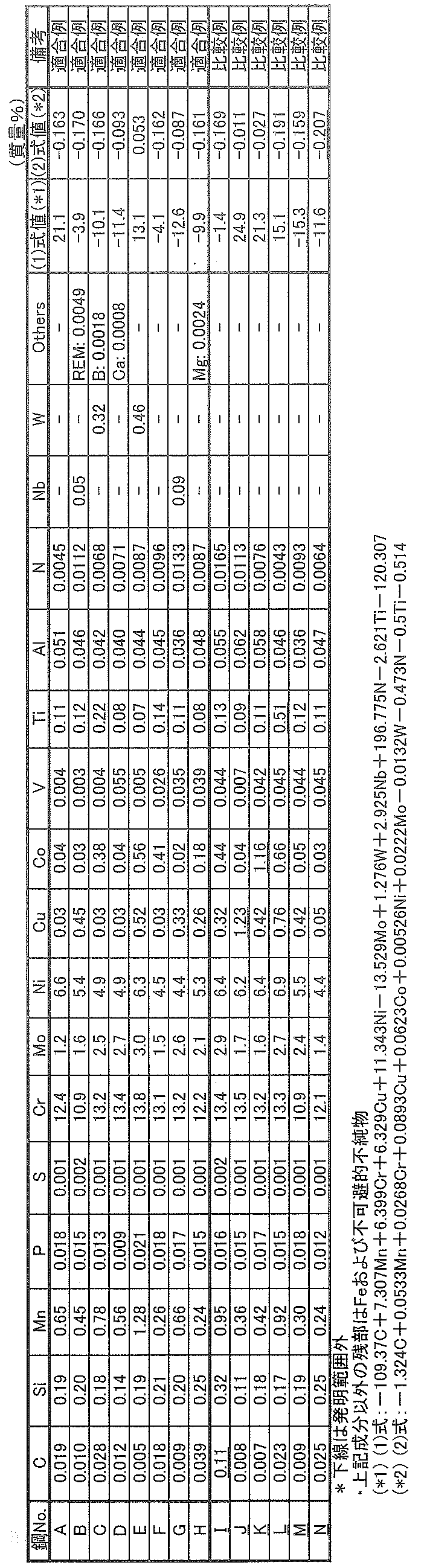
- this billet After melting the molten steel of the component shown in Table 1 with a converter, it casts into a billet (steel pipe material) by a continuous casting method. Further, this billet was formed by hot working using a model seamless rolling mill and then cooled by air cooling or water cooling to obtain a seamless steel pipe having an outer diameter of 83.8 mm and a thickness of 12.7 mm.
- a test material was cut out from the obtained seamless steel pipe, and the test material was subjected to quenching treatment and tempering treatment under the conditions shown in Table 2.
- API arc-shaped tensile test pieces are collected from the test material which has been subjected to hardening treatment and tempering treatment, and a tensile test is carried out in accordance with the provisions of API to determine tensile characteristics (yield stress YS, tensile strength TS)
- yield stress YS yield stress YS, tensile strength TS
- the In Table 2 Ac 3 transformation point (° C.) was obtained by collecting a 4 mm ⁇ ⁇ 10 mm test piece from a steel pipe and measuring it by micro displacement of expansion and contraction. Specifically, the test piece is heated to 500 ° C. at 5 ° C./s and further heated to 920 ° C. at 0.25 ° C./s to detect expansion / contraction of the test piece accompanying this temperature history, and thus Ac 3 The transformation point (° C.) was obtained
- the SSC test was performed according to NACE TM0177 Method A.
- the test environment used was prepared by adding 0.41 g / L CH 3 COONa + HCl to a 0.165 mass% NaCl aqueous solution (liquid temperature: 25 ° C., H 2 S: 1 bar, CO 2 bal) as a test solution to adjust the pH to 3.5.
- the hydrogen sulfide partial pressure was 0.1 MPa, the immersion time was 720 hours, and 90% of the yield stress was taken as the applied stress.
- produce in the test piece after a test was set as pass, and the case where a crack generate
- the martensitic stainless steels according to the present invention have excellent SSC resistance and all have high strength with a yield stress of 655 MPa or more and 758 MPa or less, and there is no occurrence of cracking even when stress is applied under an environment containing H 2 S. It is a seamless steel pipe.
- the comparative example out of the range of the present invention although the desired high strength is obtained, the excellent SSC resistance can not be secured.
Abstract
Description
[1]質量%で、
C:0.10%以下、
Si:0.5%以下、
Mn:0.05~2.0%、
P:0.030%以下、
S:0.005%以下、
Ni:4.0~8.0%、
Cu:0.02%以上1.0%未満、
Cr:10.0~14.0%、
Mo:1.0~3.5%、
V:0.003~0.2%、
Co:0.02%以上1.0%未満、
Al:0.1%以下、
N:0.1%以下、
Ti:0.50%以下
を含有する組成であり、かつ下記(1)式および(2)式を満足し、残部がFeおよび不可避的不純物からなる、降伏応力が655~758MPaの油井管用マルテンサイト系ステンレス継目無鋼管。
-15 ≦-109.37C+7.307Mn+6.399Cr+6.329Cu+11.343Ni-13.529Mo+1.276W+2.925Nb+196.775N-2.621Ti-120.307 ≦ 30 ・・・(1)
-0.20 ≦-1.324C+0.0533Mn+0.0268Cr+0.0893Cu+0.0623Co+0.00526Ni+0.0222Mo-0.0132W-0.473N-0.5Ti-0.514 ≦ 0.20 ・・・(2)
ここで、C、Mn、Cr、Cu、Co、Ni、Mo、W、Nb、N、Ti:各元素の含有量(質量%)(但し、含有しない元素は0(零)%とする。)
[2]前記組成に加えてさらに、質量%で、
Nb:0.1%以下、
W:1.0%以下
のうちから選ばれた1種または2種を含有すること特徴とする[1]に記載の降伏応力が655~758MPaの油井管用マルテンサイト系ステンレス継目無鋼管。
[3]前記組成に加えてさらに、質量%で
Ca:0.005%以下、
REM:0.010%以下、
Mg:0.010%以下、
B:0.010%以下
のうちから選ばれた1種または2種以上を含有すること特徴とする[1]または[2]に記載の降伏応力が655~758MPaの油井管用マルテンサイト系ステンレス継目無鋼管。
[4][1]~[3]のいずれかに記載の組成を有する鋼管素材を造管し鋼管としたのち、該鋼管をAc3変態点以上に加熱し、続いて100℃以下の温度まで冷却する焼入れ処理と、ついで550~680℃の温度で焼戻し処理を施すことを特徴とする降伏応力が655~758MPaの油井管用マルテンサイト系ステンレス継目無鋼管の製造方法。
[5]Ac3変態点以上に加熱し、続いて100℃以下の温度まで冷却する前記焼入れ処理における冷却速度が、0.05℃/s以上である請求項4に記載の油井管用マルテンサイト系ステンレス継目無鋼管の製造方法。
Cはマルテンサイト系ステンレス鋼の強度に関係する重要な元素であり、強度向上に有効であるが、0.10%を超える含有量では、硬度が高くなりすぎるため、硫化物応力腐食割れ感受性が増大する。このため、本発明では、C含有量は0.10%以下に限定する。また好ましくは、C含有量は0.05%以下である。一方、所望の強度を確保するために0.005%以上Cを含有することが望ましい。
Siは、脱酸剤として作用するため、0.05%以上Siを含有することが望ましい。一方で、0.5%を超えるSiの含有は、耐炭酸ガス腐食性および熱間加工性を低下させる。このため、Si含有量は0.5%以下に限定する。好ましくは、Si含有量は0.10~0.3%である。
Mnは、熱間加工性を向上させる元素であり、0.05%以上Mnを含有する。一方、2.0%を超えてMnを含有しても、その効果が飽和し、かえってコストの高騰を招く。よって、Mn含有量は0.05~2.0%に限定する。好ましくは、Mnの含有量は1.5%以下である
P:0.030%以下
Pは、耐炭酸ガス腐食性、耐孔食性、耐硫化物応力腐食割れ性をともに低下させる元素であり、本発明ではできるだけ低減させることが望ましい。しかしながら、極端な低減は製造コストを高騰させる。よって、特性の極端な低下を招かない範囲で、かつ工業的に安価に実施可能な範囲として、P含有量は0.030%以下に限定する。好ましくは、P含有量は0.020%以下である。
Sは、熱間加工性を著しく低下させる元素であるため、できるだけ低減させることが望ましい。S含有量を0.005%以下に低減することで、通常工程でのパイプ製造が可能となるため、本発明におけるS含有量は0.005%以下に限定する。好ましくは、S含有量は0.003%以下である。
Niは、4.0%以上の含有で保護被膜を強固にして耐食性を向上させ、更に固溶することで鋼の強度を増加させる。一方、Ni含有量が8.0%を超えると、マルテンサイト相の安定性が低下して、強度が低下する。よって、Ni含有量は4.0~8.0%に限定する。好ましくは、Niの含有量は7.0%以下である。
Cuは、保護被膜を強固にして耐硫化物応力腐食割れ性を向上させるため、0.02%以上含有する。しかしながら、1.0%以上のCuの含有は、CuSを析出させて熱間加工性を低下させる。よって、Cu含有量は1.0%未満に限定する。Cuは、Coとともに含有することにより、水素脆化を抑制し、耐硫化物応力腐食割れ性を向上させる。なお、より好ましくは、0.03~0.6%である。
Crは、保護被膜を形成して耐食性を向上させる元素であり、10.0%以上のCrの含有で油井管用として必要な耐食性を確保できる。一方、Cr含有量が14.0%を超えるとフェライトの生成が容易となるため、マルテンサイト相の安定確保ができなくなる。よって、Cr含有量は10.0~14.0%に限定する。好ましくは、Cr含有量は11.5~13.5%である。
Moは、Cl-による孔食に対する抵抗性を向上させる元素であり、厳しい腐食環境に必要な耐食性を得るためには、1.0%以上のMoの含有が必要である。一方、3.5%を超えるMoの含有は、上記の効果が飽和する。また、Moは高価な元素であるため、製造コストの高騰を招く。よって、Mo含有量は1.0~3.5%に限定する。好ましくは、Mo含有量は1.2~3.0%である。
Vは、析出強化によって鋼の強度を向上させ、更に耐硫化物応力腐食割れ性も向上させるため、0.003%以上の含有が必要である。一方、0.2%を超えるVの含有は、靱性が低下するため、本発明におけるV含有量は0.2%以下に限定する。好ましくは、V含有量は0.08%以下である。
Coは耐孔食性を向上させる元素であるため、0.02%以上含有する。しかしながら、過剰な含有は靱性を低下させる場合があり、更に材料コストを高騰させる。よって、Coの含有量は0.02%以上1.0%未満に限定する。Coは上述したCuとともに含有することにより、水素脆化を抑制し、耐硫化物応力腐食割れ性を向上させる。なお、より好ましくは、0.03~0.6%である。
Alは、脱酸剤として作用するため、その効果を得るためには、0.01%以上のAlの含有が有効である。しかしながら、0.1%を超えるAlの含有は、靱性に悪影響を及ぼすため、本発明におけるAl含有量は0.1%以下に限定する。好ましくは、Al含有量は0.01~0.03%である。
Nは、耐孔食性を著しく向上させる元素であるが、N含有量が0.1%超えでは、種々の窒化物を形成して靱性を低下させるため、本発明におけるN含有量は0.1%以下に限定する。好ましくは、N含有量は0.003%以上である。N含有量は、より好ましくは0.004~0.08%であり、さらに好ましくは0.005~0.05%である。
Tiは、炭化物を形成することで、固溶炭素を減少させて、硬度を低減できる。一方、過剰な含有は、靱性を低下させる場合があるため、Tiの含有量は0.50%以下、好ましくは0.30%以下に限定する。
(1)式は残留γ量に相関する式であり、(1)式の値を30以下とすることで、残留オーステナイトが低減し、硬度が低下して、耐硫化物応力腐食割れ性が向上する。一方、(1)式の値が-15未満では残留オーステナイト量に変化がなく、靭性の低下を招く。また、(2)式は孔食電位に相関する式であり、所定の範囲を満足するように、C、Mn、Cr、Cu、Co、Ni、Mo、W、N、Tiを含有することで、硫化物応力腐食割れの起点となる孔食の発生を抑制し、耐硫化物応力腐食割れ性が顕著に向上する。
-15 ≦-109.37C+7.307Mn+6.399Cr+6.329Cu+11.343Ni-13.529Mo+1.276W+2.925Nb+196.775N-2.621Ti-120.307 ≦ 30 ・・・(1)
-0.20 ≦-1.324C+0.0533Mn+0.0268Cr+0.0893Cu+0.0623Co+0.00526Ni+0.0222Mo-0.0132W-0.473N-0.5Ti-0.514 ≦ 0.20 ・・・(2)
ここで、C、Mn、Cr、Cu、Co、Ni、Mo、W、Nb、N、Ti:各元素の含有量(質量%)(但し、含有しない元素は0(零)%とする。)
さらに必要に応じて選択元素として、
Nb:0.1%以下、
W:1.0%以下
のうちから選ばれた1種または2種を含有することができる。
Ca:0.005%以下、
REM:0.010%以下、
Mg:0.010%以下、
B:0.010%以下
のうちから選ばれた1種または2種以上を含有することができる。
Ca:0.0005%以上、
REM:0.0005%以上、
Mg:0.0005%以上、
B:0.0005%以上
含有することが望ましい。一方、
Ca:0.005%、
REM:0.010%、
Mg:0.010%、
B:0.010%
を超えて含有すると、靱性および耐炭酸ガス腐食性を低下させる。よって、含有する場合には、
Ca:0.005%以下、
REM:0.010%以下、
Mg:0.010%以下、
B:0.010%以下
に限定する。
本発明では、更に鋼管を、Ac3変態点以上の温度に再加熱し、好ましくは5min以上保持し、続いて100℃以下の冷却停止温度まで冷却する。これによって、マルテンサイト相の微細化と高靱化が得られる。加熱温度がAc3変態点未満では、組織がオーステナイト単相域とならないため、その後の冷却で十分なマルテンサイト組織が得られず、所望の高強度を達成できない。よって、焼入れ加熱温度はAc3変態点以上に限定する。また、冷却方法については特に限定されず、一般に空冷(冷却速度0.05℃/s以上20℃/s以下)または水冷(冷却速度5℃/s以上100℃/s以下)により冷却し、冷却速度の条件も限定されない。しかし、組織微細化による耐食性向上の理由から0.05℃/s以上が好ましい。なお、Ac3変態点(℃)は、試験片に加熱および冷却の温度履歴を与え、膨張および収縮の微小変位による変態点測定により得ることができる。
続いて、焼入れ処理を施した鋼管に、焼戻処理を施す。焼戻処理は、鋼管を550~680℃に加熱し、好ましくは10min以上保持し、空冷する処理である。焼戻温度が550℃未満では、焼戻の効果が期待できず、所望の強度を達成できない。焼戻温度が680℃より高温になると、焼戻後にマルテンサイト相が析出し、所望の高靱性、および優れた耐食性を確保できない。よって、焼戻温度は680℃以下に限定する。なお、焼戻温度は605℃以上640℃以下が好ましい。

Claims (5)
- 質量%で、
C:0.10%以下、
Si:0.5%以下、
Mn:0.05~2.0%、
P:0.030%以下、
S:0.005%以下、
Ni:4.0~8.0%、
Cu:0.02%以上1.0%未満、
Cr:10.0~14.0%、
Mo:1.0~3.5%、
V:0.003~0.2%、
Co:0.02%以上1.0%未満、
Al:0.1%以下、
N:0.1%以下、
Ti:0.50%以下
を含有する組成であり、かつ下記(1)式および(2)式を満足し、残部がFeおよび不可避的不純物からなる、降伏応力が655~758MPaの油井管用マルテンサイト系ステンレス継目無鋼管。
記
-15 ≦-109.37C+7.307Mn+6.399Cr+6.329Cu+11.343Ni-13.529Mo+1.276W+2.925Nb+196.775N-2.621Ti-120.307 ≦ 30 ・・・(1)
-0.20 ≦-1.324C+0.0533Mn+0.0268Cr+0.0893Cu+0.0623Co+0.00526Ni+0.0222Mo-0.0132W-0.473N-0.5Ti-0.514 ≦ 0.20 ・・・(2)
ここで、C、Mn、Cr、Cu、Co、Ni、Mo、W、Nb、N、Ti:各元素の含有量(質量%)(但し、含有しない元素は0(零)%とする。) - 前記組成に加えてさらに、質量%で、
Nb:0.1%以下、
W:1.0%以下
のうちから選ばれた1種または2種を含有する請求項1に記載の降伏応力が655~758MPaの油井管用マルテンサイト系ステンレス継目無鋼管。 - 前記組成に加えてさらに、質量%で
Ca:0.005%以下、
REM:0.010%以下、
Mg:0.010%以下、
B:0.010%以下
のうちから選ばれた1種または2種以上を含有する請求項1または2に記載の降伏応力が655~758MPaの油井管用マルテンサイト系ステンレス継目無鋼管。 - 請求項1~3のいずれかに記載の組成を有する鋼管素材を造管し鋼管としたのち、該鋼管をAc3変態点以上に加熱し、続いて100℃以下の温度まで冷却する焼入れ処理と、ついで550~680℃の温度で焼戻し処理を施す、降伏応力が655~758MPaの油井管用マルテンサイト系ステンレス継目無鋼管の製造方法。
- Ac3変態点以上に加熱し、続いて100℃以下の温度まで冷却する前記焼入れ処理における冷却速度が、0.05℃/s以上である請求項4に記載の油井管用マルテンサイト系ステンレス継目無鋼管の製造方法。
Priority Applications (5)
| Application Number | Priority Date | Filing Date | Title |
|---|---|---|---|
| JP2018564432A JP6540921B1 (ja) | 2017-09-29 | 2018-09-04 | 油井管用マルテンサイト系ステンレス継目無鋼管およびその製造方法 |
| US16/646,347 US11827949B2 (en) | 2017-09-29 | 2018-09-04 | Martensitic stainless steel seamless pipe for oil country tubular goods, and method for manufacturing same |
| EP18863661.7A EP3690074A1 (en) | 2017-09-29 | 2018-09-04 | Oil well pipe martensitic stainless seamless steel pipe and production method for same |
| BR112020004793-7A BR112020004793A2 (pt) | 2017-09-29 | 2018-09-04 | tubo sem costura de aço inoxidável martensítico para produtos tubulares para regiões petrolíferas, e método para sua fabricação |
| MX2020002836A MX2020002836A (es) | 2017-09-29 | 2018-09-04 | Tubo sin costura de acero inoxidable martensitico para productos tubulares de region petrolifera, y metodo para la fabricacion del mismo. |
Applications Claiming Priority (2)
| Application Number | Priority Date | Filing Date | Title |
|---|---|---|---|
| JP2017190073 | 2017-09-29 | ||
| JP2017-190073 | 2017-09-29 |
Publications (1)
| Publication Number | Publication Date |
|---|---|
| WO2019065114A1 true WO2019065114A1 (ja) | 2019-04-04 |
Family
ID=65901715
Family Applications (1)
| Application Number | Title | Priority Date | Filing Date |
|---|---|---|---|
| PCT/JP2018/032684 WO2019065114A1 (ja) | 2017-09-29 | 2018-09-04 | 油井管用マルテンサイト系ステンレス継目無鋼管およびその製造方法 |
Country Status (7)
| Country | Link |
|---|---|
| US (1) | US11827949B2 (ja) |
| EP (1) | EP3690074A1 (ja) |
| JP (1) | JP6540921B1 (ja) |
| AR (1) | AR113183A1 (ja) |
| BR (1) | BR112020004793A2 (ja) |
| MX (1) | MX2020002836A (ja) |
| WO (1) | WO2019065114A1 (ja) |
Cited By (3)
| Publication number | Priority date | Publication date | Assignee | Title |
|---|---|---|---|---|
| WO2021131445A1 (ja) * | 2019-12-24 | 2021-07-01 | Jfeスチール株式会社 | 油井用高強度ステンレス継目無鋼管 |
| WO2021206080A1 (ja) * | 2020-04-07 | 2021-10-14 | 日本製鉄株式会社 | マルテンサイト系ステンレス継目無鋼管 |
| EP4079875A4 (en) * | 2020-05-18 | 2023-06-14 | JFE Steel Corporation | SEAMLESS STAINLESS STEEL OIL WELL TUBING AND METHOD OF MANUFACTURING THEREOF |
Families Citing this family (4)
| Publication number | Priority date | Publication date | Assignee | Title |
|---|---|---|---|---|
| US11286548B2 (en) | 2017-08-15 | 2022-03-29 | Jfe Steel Corporation | High-strength stainless steel seamless pipe for oil country tubular goods, and method for manufacturing same |
| WO2019065116A1 (ja) * | 2017-09-29 | 2019-04-04 | Jfeスチール株式会社 | 油井管用マルテンサイト系ステンレス継目無鋼管およびその製造方法 |
| MX2020002836A (es) | 2017-09-29 | 2020-07-22 | Jfe Steel Corp | Tubo sin costura de acero inoxidable martensitico para productos tubulares de region petrolifera, y metodo para la fabricacion del mismo. |
| US11794228B2 (en) * | 2021-03-18 | 2023-10-24 | Saudi Arabian Oil Company | High performance alloy for corrosion resistance |
Citations (7)
| Publication number | Priority date | Publication date | Assignee | Title |
|---|---|---|---|---|
| WO2004057050A1 (ja) | 2002-12-20 | 2004-07-08 | Sumitomo Metal Industries, Ltd. | 耐炭酸ガス腐食性および耐硫化物応力腐食割れ性に優れた高強度マルテンサイトステンレス鋼 |
| JP2007332442A (ja) | 2006-06-16 | 2007-12-27 | Jfe Steel Kk | 耐食性に優れる油井用高靭性超高強度ステンレス鋼管およびその製造方法 |
| WO2008023702A1 (fr) | 2006-08-22 | 2008-02-28 | Sumitomo Metal Industries, Ltd. | Acier inoxydable martensitique |
| JP2010242163A (ja) | 2009-04-06 | 2010-10-28 | Jfe Steel Corp | 油井管用マルテンサイト系ステンレス継目無鋼管の製造方法 |
| JP2017510715A (ja) * | 2014-02-28 | 2017-04-13 | バローレック・トゥーボス・ド・ブラジル・エス・ア | マルテンサイト‐フェライト系ステンレス鋼、並びにマルテンサイト‐フェライト系ステンレス鋼を使用する製品及び製造プロセス |
| WO2017200083A1 (ja) * | 2016-05-20 | 2017-11-23 | 新日鐵住金株式会社 | ダウンホール部材用棒鋼、及び、ダウンホール部材 |
| WO2018079111A1 (ja) * | 2016-10-25 | 2018-05-03 | Jfeスチール株式会社 | 油井管用マルテンサイト系ステンレス継目無鋼管およびその製造方法 |
Family Cites Families (14)
| Publication number | Priority date | Publication date | Assignee | Title |
|---|---|---|---|---|
| SE469986B (sv) | 1991-10-07 | 1993-10-18 | Sandvik Ab | Utskiljningshärdbart martensitiskt rostfritt stål |
| JP2000160300A (ja) * | 1998-11-27 | 2000-06-13 | Nkk Corp | 高耐食性を有する655Nmm−2級低C高Cr合金油井管およびその製造方法 |
| JP3852248B2 (ja) * | 1999-07-15 | 2006-11-29 | Jfeスチール株式会社 | 耐応力腐食割れ性に優れたマルテンサイト系ステンレス鋼の製造方法 |
| JP2001107198A (ja) * | 1999-10-07 | 2001-04-17 | Nippon Steel Corp | 耐ssc性に優れたマルテンサイト系ステンレス鋼ラインパイプおよびその製造方法 |
| JP3966136B2 (ja) * | 2002-09-20 | 2007-08-29 | Jfeスチール株式会社 | 耐食性に優れたラインパイプ用ステンレス鋼管 |
| JP4400423B2 (ja) * | 2004-01-30 | 2010-01-20 | Jfeスチール株式会社 | マルテンサイト系ステンレス鋼管 |
| JP6102798B2 (ja) * | 2014-02-28 | 2017-03-29 | Jfeスチール株式会社 | リールバージ敷設に優れるラインパイプ用マルテンサイト系ステンレス鋼管の製造方法 |
| EP3121306B1 (en) | 2014-05-21 | 2020-06-24 | JFE Steel Corporation | High-strength seamless stainless steel pipe for oil country tubular goods and method for manufacturing the same |
| JP6390677B2 (ja) * | 2015-08-18 | 2018-09-19 | Jfeスチール株式会社 | 低炭素マルテンサイト系ステンレス鋼溶接管およびその製造方法 |
| WO2017168874A1 (ja) * | 2016-03-29 | 2017-10-05 | Jfeスチール株式会社 | 油井用高強度ステンレス継目無鋼管 |
| CN110312816A (zh) | 2017-02-24 | 2019-10-08 | 杰富意钢铁株式会社 | 油井用高强度不锈钢无缝钢管及其制造方法 |
| EP3604591A4 (en) | 2017-03-28 | 2020-09-02 | Nippon Steel Corporation | MARTENSITIC STAINLESS STEEL MATERIAL |
| US11286548B2 (en) | 2017-08-15 | 2022-03-29 | Jfe Steel Corporation | High-strength stainless steel seamless pipe for oil country tubular goods, and method for manufacturing same |
| MX2020002836A (es) | 2017-09-29 | 2020-07-22 | Jfe Steel Corp | Tubo sin costura de acero inoxidable martensitico para productos tubulares de region petrolifera, y metodo para la fabricacion del mismo. |
-
2018
- 2018-09-04 MX MX2020002836A patent/MX2020002836A/es unknown
- 2018-09-04 BR BR112020004793-7A patent/BR112020004793A2/pt not_active Application Discontinuation
- 2018-09-04 EP EP18863661.7A patent/EP3690074A1/en active Pending
- 2018-09-04 US US16/646,347 patent/US11827949B2/en active Active
- 2018-09-04 JP JP2018564432A patent/JP6540921B1/ja active Active
- 2018-09-04 WO PCT/JP2018/032684 patent/WO2019065114A1/ja unknown
- 2018-09-27 AR ARP180102772A patent/AR113183A1/es active IP Right Grant
Patent Citations (7)
| Publication number | Priority date | Publication date | Assignee | Title |
|---|---|---|---|---|
| WO2004057050A1 (ja) | 2002-12-20 | 2004-07-08 | Sumitomo Metal Industries, Ltd. | 耐炭酸ガス腐食性および耐硫化物応力腐食割れ性に優れた高強度マルテンサイトステンレス鋼 |
| JP2007332442A (ja) | 2006-06-16 | 2007-12-27 | Jfe Steel Kk | 耐食性に優れる油井用高靭性超高強度ステンレス鋼管およびその製造方法 |
| WO2008023702A1 (fr) | 2006-08-22 | 2008-02-28 | Sumitomo Metal Industries, Ltd. | Acier inoxydable martensitique |
| JP2010242163A (ja) | 2009-04-06 | 2010-10-28 | Jfe Steel Corp | 油井管用マルテンサイト系ステンレス継目無鋼管の製造方法 |
| JP2017510715A (ja) * | 2014-02-28 | 2017-04-13 | バローレック・トゥーボス・ド・ブラジル・エス・ア | マルテンサイト‐フェライト系ステンレス鋼、並びにマルテンサイト‐フェライト系ステンレス鋼を使用する製品及び製造プロセス |
| WO2017200083A1 (ja) * | 2016-05-20 | 2017-11-23 | 新日鐵住金株式会社 | ダウンホール部材用棒鋼、及び、ダウンホール部材 |
| WO2018079111A1 (ja) * | 2016-10-25 | 2018-05-03 | Jfeスチール株式会社 | 油井管用マルテンサイト系ステンレス継目無鋼管およびその製造方法 |
Non-Patent Citations (1)
| Title |
|---|
| See also references of EP3690074A4 |
Cited By (8)
| Publication number | Priority date | Publication date | Assignee | Title |
|---|---|---|---|---|
| WO2021131445A1 (ja) * | 2019-12-24 | 2021-07-01 | Jfeスチール株式会社 | 油井用高強度ステンレス継目無鋼管 |
| JP6950851B1 (ja) * | 2019-12-24 | 2021-10-13 | Jfeスチール株式会社 | 油井用高強度ステンレス継目無鋼管 |
| CN114829647A (zh) * | 2019-12-24 | 2022-07-29 | 杰富意钢铁株式会社 | 油井用高强度不锈钢无缝钢管 |
| EP4043591A4 (en) * | 2019-12-24 | 2022-10-12 | JFE Steel Corporation | HIGH STRENGTH STAINLESS STEEL SEAMLESS PIPE FOR OIL WELL |
| WO2021206080A1 (ja) * | 2020-04-07 | 2021-10-14 | 日本製鉄株式会社 | マルテンサイト系ステンレス継目無鋼管 |
| JPWO2021206080A1 (ja) * | 2020-04-07 | 2021-10-14 | ||
| JP7397375B2 (ja) | 2020-04-07 | 2023-12-13 | 日本製鉄株式会社 | マルテンサイト系ステンレス継目無鋼管 |
| EP4079875A4 (en) * | 2020-05-18 | 2023-06-14 | JFE Steel Corporation | SEAMLESS STAINLESS STEEL OIL WELL TUBING AND METHOD OF MANUFACTURING THEREOF |
Also Published As
| Publication number | Publication date |
|---|---|
| US11827949B2 (en) | 2023-11-28 |
| BR112020004793A2 (pt) | 2020-09-24 |
| JP6540921B1 (ja) | 2019-07-10 |
| MX2020002836A (es) | 2020-07-22 |
| JPWO2019065114A1 (ja) | 2019-11-14 |
| EP3690074A4 (en) | 2020-08-05 |
| AR113183A1 (es) | 2020-02-05 |
| US20200283866A1 (en) | 2020-09-10 |
| EP3690074A1 (en) | 2020-08-05 |
Similar Documents
| Publication | Publication Date | Title |
|---|---|---|
| JP6540922B1 (ja) | 油井管用マルテンサイト系ステンレス継目無鋼管およびその製造方法 | |
| JP6540921B1 (ja) | 油井管用マルテンサイト系ステンレス継目無鋼管およびその製造方法 | |
| JP6315159B1 (ja) | 油井管用マルテンサイト系ステンレス継目無鋼管およびその製造方法 | |
| JP5145793B2 (ja) | 油井管用マルテンサイト系ステンレス継目無鋼管およびその製造方法 | |
| JP6540920B1 (ja) | 油井管用マルテンサイト系ステンレス継目無鋼管およびその製造方法 | |
| WO2017162160A1 (zh) | 耐硫化氢应力腐蚀开裂的马氏体不锈钢油套管用钢、油套管及其制造方法 | |
| JP6680409B1 (ja) | 油井管用マルテンサイト系ステンレス継目無鋼管およびその製造方法 | |
| JP6743992B1 (ja) | 油井管用マルテンサイト系ステンレス継目無鋼管およびその製造方法 | |
| JP2007332442A (ja) | 耐食性に優れる油井用高靭性超高強度ステンレス鋼管およびその製造方法 | |
| JP5499575B2 (ja) | 油井管用マルテンサイト系ステンレス継目無鋼管およびその製造方法 | |
| KR101539520B1 (ko) | 2상 스테인리스강 | |
| JP6680408B1 (ja) | 油井管用マルテンサイト系ステンレス継目無鋼管およびその製造方法 | |
| JP6747628B1 (ja) | 二相ステンレス鋼、継目無鋼管、および二相ステンレス鋼の製造方法 | |
| JP6303878B2 (ja) | マルテンサイト系Cr含有鋼材 | |
| JP5837436B2 (ja) | 継目無油井管用マルテンサイト系ステンレス鋼およびその製造方法 | |
| JP2001316772A (ja) | 大径シームレス鋼管用マルテンサイト系ステンレス鋼 |
Legal Events
| Date | Code | Title | Description |
|---|---|---|---|
| ENP | Entry into the national phase |
Ref document number: 2018564432 Country of ref document: JP Kind code of ref document: A |
|
| 121 | Ep: the epo has been informed by wipo that ep was designated in this application |
Ref document number: 18863661 Country of ref document: EP Kind code of ref document: A1 |
|
| REG | Reference to national code |
Ref country code: BR Ref legal event code: B01A Ref document number: 112020004793 Country of ref document: BR |
|
| NENP | Non-entry into the national phase |
Ref country code: DE |
|
| ENP | Entry into the national phase |
Ref document number: 2018863661 Country of ref document: EP Effective date: 20200429 |
|
| ENP | Entry into the national phase |
Ref document number: 112020004793 Country of ref document: BR Kind code of ref document: A2 Effective date: 20200310 |