WO2019064855A1 - 充放電装置 - Google Patents
充放電装置 Download PDFInfo
- Publication number
- WO2019064855A1 WO2019064855A1 PCT/JP2018/027511 JP2018027511W WO2019064855A1 WO 2019064855 A1 WO2019064855 A1 WO 2019064855A1 JP 2018027511 W JP2018027511 W JP 2018027511W WO 2019064855 A1 WO2019064855 A1 WO 2019064855A1
- Authority
- WO
- WIPO (PCT)
- Prior art keywords
- charge
- communication
- discharge device
- controller
- discharge
- Prior art date
- Legal status (The legal status is an assumption and is not a legal conclusion. Google has not performed a legal analysis and makes no representation as to the accuracy of the status listed.)
- Ceased
Links
Images






Classifications
-
- H—ELECTRICITY
- H02—GENERATION; CONVERSION OR DISTRIBUTION OF ELECTRIC POWER
- H02J—ELECTRIC POWER NETWORKS; CIRCUIT ARRANGEMENTS OR SYSTEMS FOR SUPPLYING OR DISTRIBUTING ELECTRIC POWER; SYSTEMS FOR STORING ELECTRIC ENERGY
- H02J3/00—Circuit arrangements for AC mains or AC distribution networks
- H02J3/28—Arrangements for balancing of the load in networks by storage of energy
- H02J3/32—Arrangements for balancing of the load in networks by storage of energy using batteries or super capacitors with converting means
- H02J3/322—Arrangements for balancing of the load in networks by storage of energy using batteries or super capacitors with converting means the battery being on-board an electric or hybrid vehicle, e.g. vehicle to grid arrangements [V2G], power aggregation, use of the battery for network load balancing, coordinated or cooperative battery charging
-
- H—ELECTRICITY
- H01—ELECTRIC ELEMENTS
- H01M—PROCESSES OR MEANS, e.g. BATTERIES, FOR THE DIRECT CONVERSION OF CHEMICAL ENERGY INTO ELECTRICAL ENERGY
- H01M10/00—Secondary cells; Manufacture thereof
- H01M10/42—Methods or arrangements for servicing or maintenance of secondary cells or secondary half-cells
- H01M10/44—Methods for charging or discharging
-
- H—ELECTRICITY
- H02—GENERATION; CONVERSION OR DISTRIBUTION OF ELECTRIC POWER
- H02J—ELECTRIC POWER NETWORKS; CIRCUIT ARRANGEMENTS OR SYSTEMS FOR SUPPLYING OR DISTRIBUTING ELECTRIC POWER; SYSTEMS FOR STORING ELECTRIC ENERGY
- H02J13/00—Circuit arrangements for providing remote monitoring or remote control of equipment in a power distribution network
-
- H—ELECTRICITY
- H02—GENERATION; CONVERSION OR DISTRIBUTION OF ELECTRIC POWER
- H02J—ELECTRIC POWER NETWORKS; CIRCUIT ARRANGEMENTS OR SYSTEMS FOR SUPPLYING OR DISTRIBUTING ELECTRIC POWER; SYSTEMS FOR STORING ELECTRIC ENERGY
- H02J7/00—Circuit arrangements for charging or discharging batteries or for supplying loads from batteries
-
- Y—GENERAL TAGGING OF NEW TECHNOLOGICAL DEVELOPMENTS; GENERAL TAGGING OF CROSS-SECTIONAL TECHNOLOGIES SPANNING OVER SEVERAL SECTIONS OF THE IPC; TECHNICAL SUBJECTS COVERED BY FORMER USPC CROSS-REFERENCE ART COLLECTIONS [XRACs] AND DIGESTS
- Y02—TECHNOLOGIES OR APPLICATIONS FOR MITIGATION OR ADAPTATION AGAINST CLIMATE CHANGE
- Y02E—REDUCTION OF GREENHOUSE GAS [GHG] EMISSIONS, RELATED TO ENERGY GENERATION, TRANSMISSION OR DISTRIBUTION
- Y02E60/00—Enabling technologies; Technologies with a potential or indirect contribution to GHG emissions mitigation
- Y02E60/10—Energy storage using batteries
-
- Y—GENERAL TAGGING OF NEW TECHNOLOGICAL DEVELOPMENTS; GENERAL TAGGING OF CROSS-SECTIONAL TECHNOLOGIES SPANNING OVER SEVERAL SECTIONS OF THE IPC; TECHNICAL SUBJECTS COVERED BY FORMER USPC CROSS-REFERENCE ART COLLECTIONS [XRACs] AND DIGESTS
- Y02—TECHNOLOGIES OR APPLICATIONS FOR MITIGATION OR ADAPTATION AGAINST CLIMATE CHANGE
- Y02T—CLIMATE CHANGE MITIGATION TECHNOLOGIES RELATED TO TRANSPORTATION
- Y02T90/00—Enabling technologies or technologies with a potential or indirect contribution to GHG emissions mitigation
- Y02T90/10—Technologies relating to charging of electric vehicles
- Y02T90/16—Information or communication technologies improving the operation of electric vehicles
- Y02T90/167—Systems integrating technologies related to power network operation and communication or information technologies for supporting the interoperability of electric or hybrid vehicles, i.e. smartgrids as interface for battery charging of electric vehicles [EV] or hybrid vehicles [HEV]
Definitions
- the present invention relates to an apparatus for controlling charging and / or discharging of a storage battery.
- Patent Document 1 is for coping with a case where in the charging device provided in the electric vehicle, the start signal can not be received from the charger provided outside the electric vehicle. Specifically, the charging device detects a state in which the start signal can not be received as a communication error, and when the communication error is detected, the charging device continues until a predetermined time has elapsed since the start operation unit of the electric vehicle is turned off. Continue to supply power for operation.
- Patent Document 2 is for utilizing surplus power conveniently for the user. Specifically, when the surplus power occurs, the controller advances the time of the schedule classified into the group permitted to accelerate the time among the power consumption schedules stored in the storage unit.
- Patent Documents 1 and 2 the operation control of the charge / discharge device considering the communication state between the controller such as the HEMS controller and the charge / discharge device provided outside the electric vehicle for charging the electric vehicle Is not disclosed at all.
- the technology of Patent Document 1 it is determined whether the charging device provided in the electric vehicle can receive a start signal from a charger (corresponding to the charging / discharging device) provided outside the electric vehicle.
- the technology does not determine the communication state with the controller connected with the charger.
- the charge / discharge device can not confirm the state of communication with the controller.
- a cause of the disconnection of the communication for example, power off of the controller or the HUB or disconnection of the communication cable may be mentioned.
- the charge / discharge device can not receive the control scheduled by the controller with the disconnection of the communication, and thus can not perform desired charging or discharging.
- the charge and discharge device continues the operation based on the operation instruction from the controller before disconnection. For example, when the operation instruction is an instruction to perform a discharging operation, the remaining battery capacity of the storage battery is exhausted.
- An object of one embodiment of the present invention is to realize a charge / discharge device capable of improving convenience when communication with a controller is not possible.
- a charge / discharge device includes at least a charge operation for charging a storage battery with external power and a discharge operation for taking out the power stored in the storage battery and supplying the power to the outside.
- a communication unit that communicates control information with a controller that controls the charge / discharge device; a communication determination unit that determines whether the communication is enabled or not; And a process execution unit that executes a predetermined process when the communication determination unit determines that the communication is not possible.
- the charge / discharge device includes a charge / discharge device capable of performing both the charge operation and the discharge operation (see Embodiment 1), a charge device performing only the charge operation (see Embodiment 2), Also, it refers to any device of the discharge device (see Embodiment 3) that performs only the discharge operation. That is, the charge / discharge device according to the claims is a concept including the charge / discharge device, the charge device, and the discharge device.
- Embodiment 1 Hereinafter, embodiments of the present invention will be described in detail.
- FIG. 1 is a schematic configuration diagram of a power supply system 1 including a charge / discharge device 100 according to an embodiment of the present invention.
- the power supply system 1 includes, for example, a commercial power system 2 (commercial system), a distribution board 3, an EMS (Energy Management System) controller 4, an electric vehicle 5, a HUB 6 (line concentrator), and a charge / discharge device 100. , A plurality of devices 110, and a plurality of loads 120.
- the commercial power grid 2 is a power grid from a power company.
- the power system is a system that integrates power generation, transformation, transmission and distribution to supply power.
- the distribution board 3 is connected to the commercial power system 2.
- Commercial AC power of a prescribed voltage (100 V / 200 V) is supplied from the commercial power system 2 to the distribution board 3.
- AC power is supplied to the charge / discharge device 100, the plurality of devices 110, and the plurality of loads 120 through the distribution board 3.
- the charge / discharge device 100 and the like operate using AC power (or DC power converted from AC power) supplied through the distribution board 3.
- the distribution board 3 includes a master breaker (not shown).
- the main breaker is provided on a bus within the distribution board 3 and is used to switch between conduction and non-conduction of three-phase wiring (three-phase three-wire system) constituting the bus.
- the wiring form of the main breaker is not limited to the three-phase three-wire system, and may be, for example, a single-phase three-wire system or a single-phase two-wire system.
- the distribution board 3 includes sensors (not shown) for measuring various types of power. A smart meter (not shown) provided between the commercial power grid 2 and the distribution board 3 may notify the EMS controller 4 of information on the power detected by the sensor.
- the EMS controller 4 is a controller (control device) that mainly controls and manages the charge / discharge device 100 and the plurality of devices 110. Specifically, the EMS controller 4 is connected to the charge / discharge device 100 and the plurality of devices 110 via a communication cable (for example, a LAN (Local Area Network) cable). The EMS controller 4 controls each operation mode of the charge / discharge device 100 and the plurality of devices 110.
- a communication cable for example, a LAN (Local Area Network) cable.
- the centralized controller 7 of the server connected to the network may control and manage the charge / discharge device 100 and the like.
- the centralized controller 7 causes the EMS controller 4 to control and manage the charge / discharge device 100 and the like by transmitting an instruction related to the charge or discharge operation or an instruction related to the charge amount or the discharge amount to the EMS controller 4. That is, an instruction from the centralized controller 7 to the charge / discharge device 100 or the like is performed via the EMS controller 4.
- the communication between the centralized controller 7 and the EMS controller 4 is not necessarily communication based on the ECHONET Lite (registered trademark) standard described later.
- the central controller 7 can directly control and manage the charge / discharge device 100 etc. instead of the EMS controller 4.
- the charge / discharge device 100 or the like sets the “remote operation setting” property included in the instruction, which is an instruction from the EMS controller 4 or an instruction from another controller (eg, the centralized controller 7) through the network. Identify by (through public line / not through).
- the EMS controller 4 functions as a HEMS controller.
- the EMS controller 4 functions as a Building Energy Management System (BEMS) controller.
- BEMS Building Energy Management System
- FEMS Factory Energy Management System
- the EMS controller 4 functions as a Community Energy Management System (CEMS) controller.
- EMS controller 4 should just be a controller (control device) which controls and manages charging / discharging device 100 and a plurality of apparatus 110 mainly, and is not limited to each above-mentioned controller.
- the EMS controller 4 is connected to various servers via a network.
- the various servers store, for example, information such as a purchase unit price of power supplied from the commercial power grid 2, a sale unit price of power supplied to the commercial power grid 2, and a purchase unit price of fuel gas.
- the electrically powered vehicle 5 carries a large-capacity on-board storage battery 51 (storage battery) for storing electric power used during traveling. At the time of a power failure of the commercial power grid 2, the power in the on-board storage battery 51 is supplied by the charge / discharge device 100 to the plurality of devices 110 and the plurality of loads 120.
- Electric powered vehicle 5 includes a storage battery for driving, and includes various vehicles capable of traveling by converting the power in the storage battery into a driving force. Examples of the vehicle include an electric vehicle (EV), a plug-in hybrid vehicle (PHV), a plug-in hybrid electric vehicle (PHEV), and a fuel cell vehicle (FCV). It can be mentioned.
- the control target of the charge / discharge device 100 may not be the electric vehicle 5, and may be, for example, a chargeable / dischargeable storage battery. In addition, it may be a control target exemplified in the second and third embodiments described later.
- the power supply process at the time of the blackout is particularly referred to as a self-sustaining operation of the charge / discharge device 100.
- the power in the on-vehicle storage battery 51 can be supplied to the plurality of devices 110 and the like also at the time of non-power failure.
- AC power is supplied from both of the commercial power system 2 and the charge / discharge device 100 to the plurality of devices 110 and the like.
- the power supply processing at the time of non-power failure is particularly referred to as grid-connected operation of the charge / discharge device 100.
- the plurality of devices 110 are devices having a communication function, such as an air conditioner, a refrigerator, or an induction heating (IH) cooking heater.
- the plurality of loads 120 are, for example, load devices connected to an outlet. In addition, it is unfixed what kind of load apparatus is connected to an outlet.
- the power supply system 1 generates an electric power using a PV (solar power generation) device that generates electric power according to the reception of sunlight as a control target of the EMS controller 4 and / or a fuel (gas). (Fuel cell) may be included.
- PV solar power generation
- FC device are examples of a power generation device.
- the PV device and the FC device operate using AC power supplied from the charge / discharge device 100 during independent operation, and can also perform grid-connected operation.
- the power supply system 1 also includes a router (not shown) connected to the HUB 6.
- the router enables communication connection between a server or the like connected to a network, the EMS controller 4, the charge / discharge device 100, and a plurality of devices 110.
- the router is particularly required when the centralized controller 7 controls and manages the charge / discharge device 100 and the like. Note that the router of the present embodiment may have the function of the EMS controller 4.
- the EMS controller 4 and each device are connected via the HUB 6. Communication between the EMS controller 4 and the charge / discharge device 100 and the plurality of devices 110 is performed in a method according to a predetermined protocol.
- the predetermined protocol includes, for example, a protocol called ECHONET Lite or ECHONET (registered trademark).
- the charge / discharge device 100 and the plurality of devices 110 are devices corresponding to the ECHONET Lite standard or the ECHONET standard.
- the predetermined protocol may be a protocol other than ECHONET Lite and ECHONET.
- the plurality of loads 120 are not devices compliant with the ECHONET Lite standard or the ECHONET standard, and do not communicate with the EMS controller 4.
- the EMS controller 4 and devices such as the charge / discharge device 100 are connected via the HUB 6.
- the power supply system 1 need not necessarily have the HUB 6.
- the EMS controller 4 and devices such as the charge / discharge device 100 perform direct one-to-one communication.
- the predetermined protocol is ECHONET Lite
- the charge / discharge device 100 and the plurality of devices 110 are devices corresponding to the ECHONET Lite standard.
- the charge / discharge device 100 mainly includes a charge / discharge circuit 111, a control unit 112, an input unit 113, a display unit 114, a clock unit 115, and a communication unit 116.
- Charge / discharge device 100 is both charging commercial power system 2 to on-board storage battery 51 mounted on electric vehicle 5, and supplying power from on-board storage battery 51 of electric vehicle 5 to the plurality of devices 110 and the plurality of loads 120. Used for That is, the charge / discharge device 100 performs both the charging operation of charging the on-board storage battery 51 with external power and the discharge operation of taking out the power stored in the on-board storage battery 51 and supplying the power to the outside. Further, the charge / discharge device 100 can communicate control information with the EMS controller 4 via the HUB 6.
- the charge and discharge circuit 111 charges the on-vehicle storage battery 51 (charging operation). In addition, the charge / discharge circuit 111 takes out direct current power from the on-board storage battery 51 at the time of the independent operation or at the time of the grid connection operation. The charge and discharge circuit 111 converts DC power extracted from the in-vehicle storage battery 51 into AC power of a predetermined voltage, and supplies the AC power to the plurality of devices 110 and the plurality of loads 120. The plurality of devices 110 and the plurality of loads 120 operate using alternating current power supplied from the charge and discharge device 100.
- the control unit 112 centrally controls the operation (for example, charge and discharge) of the charge / discharge device 100.
- the control unit 112 mainly includes a communication determination unit 11, a mode setting unit 12, a charge and discharge control unit 13, and a notification control unit 14.
- the communication determination unit 11 determines whether communication with the EMS controller 4 (ECHONET Lite communication) is possible. In the present embodiment, the communication determination unit 11 determines whether the communication is not possible after the start of the communication when the charge / discharge device 100 enters the network.
- the following (A) to (D), for example, may be mentioned as a method of determining whether or not the communication has not been enabled.
- the communication determination unit 11 performs processing according to the predetermined startup procedure defined in the standard except when the ECHONET Lite communication is started up. Then, the above determination is made. At the time of the start-up, the following processing is performed.
- the start-up refers to processing for enabling communication between the EMS controller 4 and the charge / discharge device 100 when the charge / discharge device 100 enters the network in which the EMS controller 4 exists.
- the control unit 112 (in the present embodiment, the communication determination unit 11) notifies the network to which the own device is connected that the presence of the own device is notified. Perform instance list notification).
- the EMS controller 4 on the network sends a status notification (GET) to the charge / discharge device 100 to request notification of information on the status of the charge / discharge device 100.
- the control unit 112 acquires the status notification, the control unit 112 returns the information (property value) indicated in the status notification to the EMS controller 4. That is, it can be said that the above-mentioned state notification makes a request for communicating properties or property values to the EMS controller 4 (unicast) to the device such as the charge / discharge device 100.
- the communication determination unit 11 sends a startup notification at times other than startup, and determines that communication has been received from the EMS controller 4 when the status notification for that is obtained from the EMS controller 4. In other words, in this case, the communication determination unit 11 determines that communication with the EMS controller 4 is possible (the communication state with the EMS controller 4 is maintained). On the other hand, when the communication determination unit 11 does not obtain the status notification for the startup notification, the communication determination unit 11 determines that the communication is in a disabled state.
- the communication determination unit 11 acquires the IP (Internet Protocol) address or the MAC (Media Access Control) address of the EMS controller 4 and stores it in the storage unit (not shown) of the own device. .
- the communication determination unit 11 may determine whether or not the IP address or MAC address acquired other than at the time of startup matches the IP address or MAC address acquired at the time of startup. In this case, the communication determination unit 11 determines that the communication is possible when the two match, and determines that the communication is not possible when the two do not match.
- the EMS controller 4 When the EMS controller 4 receives a response to the status notification from the charge / discharge device 100, the EMS controller 4 performs status setting notification requesting setting or change of information (property value) related to the status of the charge / discharge device 100 at the time of startup.
- the control unit 112 sets or changes the information of the own device based on the status setting notification. That is, the state setting notification can also be said to request the device such as the charge / discharge device 100 to set the property or the property value.
- the EMS controller 4 often performs status notification or status setting notification at predetermined time intervals other than at startup. For example, it is considered that status notification is periodically performed for image display or log collection on the EMS controller 4 side. In the determination as to whether or not communication with the EMS controller 4 is possible, it is useful to determine whether the status notification or the status setting notification has been acquired as described above.
- the communication determination unit 11 may perform the above determination based on whether or not acquisition of information other than status notification or status setting notification is possible. For example, when the second state notification (ANNOUNCE) is acquired within a predetermined time, the communication determination unit 11 determines that the communication is possible.
- the second state notification means making a request for communicating the property or property value to the entire network (by multicast) to the device such as the charge / discharge device 100.
- the communication determination unit 11 performs status notification (GET) to request the EMS controller 4 to send information on the status of the EMS controller 4.
- the communication determination unit 11 determines that the communication is possible when the EMS controller 4 responds to the status notification, and when the response is not received, the communication is not possible. Determined to fall.
- response there are a “response” that responds to operating as a request for status notification, and an “impossible response” that returns status notification but that it does not operate as a status notification request. is there.
- (D) Communication determination based on establishment / nonexistence of link of communication cable The communication determination unit 11 determines whether the charge / discharge device 100 is connected to the communication cable and the HUB 6 to which the communication cable is connected (or via the HUB 6) It is determined whether or not communication with the connected partner device is possible. That is, the communication determination unit 11 determines whether the link of the communication cable is established. The communication determination unit 11 determines that the communication is possible when the link is established, and determines that the communication is not possible when the link is not established.
- the active link LED Light Emitting Diode
- the communication determination unit 11 determines that the communication is possible when the link is established, it can not specify the other device connected via the communication cable. Therefore, even when the link is established, the communication is not necessarily possible. However, in the present embodiment, if the link is established, it is determined that the communication is possible.
- the communication judging unit 11 (1) In the case where the status notification (including the status notification as a response to the startup notification), the second status notification or the status setting notification is not received as predetermined data from the EMS controller 4, or (2) When a communication cable link connecting charge / discharge device 100 and HUB 6 is not established, It is determined that the above-mentioned communication is in an impossible state.
- the present invention is not limited to this. It does not matter.
- the communication determination unit 11 (11) Every predetermined time, (12) When the charging rate (SOC: State of Charge) of the in-vehicle storage battery 51 changes, (13) When the electric vehicle 5 is connected, or (14) When the start operation for starting control in the EMS control mode (described later) is acquired, A determination is made as to whether or not the communication has been disabled.
- SOC State of Charge
- the connector of the charge / discharge device 100 is connected to the charge port of the electric vehicle 5, or the communication with the electric vehicle 5 is started.
- Point to The “start operation” of (14) is realized, for example, by the user turning on the start button for starting the control via the input unit 113.
- the timing at which the above determination is made is not limited to the timings of (11) to (14) above, while the charge / discharge device 100 is stopped, in operation, connected to the electric vehicle 5, or in standby for charging or discharging operation. It may be performed at any timing in any of the states. Further, the determination of the state of the communication may be continued even after it is determined that the communication is in an impossible state.
- determination method and timing which determination method and at which timing the above determination is performed may be set in advance. In addition, it may be set by the type of the connected electric vehicle 5 (the type of the on-board storage battery 51) or by user operation.
- the mode setting unit 12, the charge and discharge control unit 13, and the notification control unit 14 function as a process execution unit that executes a predetermined process when the communication determination unit 11 determines that the communication is not possible.
- the predetermined process is a process predetermined as a process to be executed when it is determined that the communication has been disabled.
- the predetermined process includes a process (also referred to as a first predetermined process) predetermined as a process to be executed when the control from the EMS controller 4 changes to a state in which the control can not be received. Note that among the predetermined processes, a process different from the first predetermined process is also referred to as a second predetermined process.
- the mode setting unit 12 sets the operation mode of the charge / discharge device 100 to either the EMS control mode (first control mode) or the main body operation mode (second control mode).
- the EMS control mode is a mode in which the vehicle storage battery 51 is operated under the control of the EMS controller 4.
- the main body operation mode is a mode in which an operation is performed on the on-board storage battery 51 autonomously without receiving control of the EMS controller 4.
- the EMS control mode can be said to be an operation mode capable of receiving various instructions in the ECHONET Lite standard.
- the mode setting unit 12 performs processing of switching the EMS control mode to the main body operation mode or processing of setting the operation mode to the main body operation mode as the predetermined process when it is determined that the communication is not possible. .
- the mode setting unit 12 may perform a process of switching from a user selectable state to a user non-selectable state as the predetermined process. In this case, the mode setting unit 12 displays, on the display unit 114, a selection image of an operation mode in which the user operation for selecting the EMS control mode can not be received.
- the mode setting unit 12 may set the EMS control mode or the main body operation mode in accordance with the user operation acquired via the input unit 113.
- the charge and discharge control unit 13 controls the charge and discharge circuit 111 to control the charge operation or the discharge operation of the on-vehicle storage battery 51.
- the charge / discharge control unit 13 When the charge / discharge control unit 13 is set in the EMS control mode, the charge / discharge control unit 13 starts the charging operation or the discharging operation of the in-vehicle storage battery 51 and stops these operations according to the operation instruction from the EMS controller 4. Further, the charge / discharge control unit 13 waits for the start of the charge operation or the discharge operation according to the operation instruction.
- the main body operation mode may be referred to as a reservation operation mode.
- the reserved operation mode is a mode in which the charging operation or the discharging operation is performed in accordance with a reserved time (start time and end time) preset in the charge / discharge device 100. It is also preset which of the charging operation and the discharging operation is performed.
- the charging operation or the discharging operation in the reservation operation mode may be referred to as a reservation operation.
- the electric vehicle 5 for example, PV or FCV
- the electric vehicle 5 can not perform the reservation operation. Therefore, in the case of the electrically powered vehicle 5, the process of (23) is performed instead of the (21).
- the main body operation mode may be referred to as an operation continuation mode.
- the EMS controller 4 and the charge / discharge device 100 may have specifications that can perform ECHONET Lite communication in the reserved operation mode. However, in this case, the EMS controller 4 can perform the state notification but can not perform the state setting notification (the charge / discharge device 100 returns an impossible response to the state setting notification). In addition, when ECHONET Lite communication is established during the reserved operation (when the communication determination unit 11 determines that the above-mentioned communication can not be made to the enabled state), the reserved operation mode is shifted to the EMS control mode. I don't care.
- the main body operation mode may be referred to as a forced charging mode in which the charging operation is forcibly performed. That is, if the control content is to cause the charge / discharge device 100 to perform the charge operation, the charge operation is continued as it is. If the control content is to cause the charge / discharge device 100 to perform the discharging operation or to cause the charging operation or the discharging operation to stand by, the operation is switched to the charging operation.
- the charging does not have to be performed up to the charging upper limit capacity, and the charging may be performed to a predetermined capacity. In the present embodiment, it is assumed that the charging is performed up to the charging upper limit capacity.
- the charge / discharge control unit 13 performs any of the processes (21) to (23) when the mode is switched to the main body operation mode as the predetermined process. That is, it can be said that the main body operation mode is a mode in which any one of the above (21) to (23) is performed.
- the charge / discharge control unit 13 stops the charging operation or the discharging operation as the predetermined process.
- the process to switch to the main body operation mode or the process to be stopped is performed, or to which process of (21) to (23) is performed when the main body operation mode is switched, It may be set in advance. In addition, it may be set by the type of the connected electric vehicle 5 (the type of the on-board storage battery 51) or by user operation.
- the notification control unit 14 performs notification (notification of abnormality) indicating that the communication has been disabled as the predetermined process.
- the notification control unit 14 performs the notification by at least one of the following methods (31) to (34). It may be set in advance which of these processes is to be used for the notification.
- a display image indicating an abnormality is displayed on the display unit 114. It may be notified by sound instead of display. An abnormality may be notified by display and sound.
- the display image is displayed on an external device (for example, a portable information terminal such as a smartphone or a tablet) other than the device compliant with the ECHONET Lite standard with which the charge / discharge device 100 can communicate.
- an external device for example, a portable information terminal such as a smartphone or a tablet
- an application for notifying abnormality is installed in the external device.
- an abnormality may be notified by sound.
- the EMS controller 4 or the external device transmits an e-mail in which a text indicating an abnormality is described.
- a mail is transmitted to the EMS controller 4, the above communication is performed.
- the abnormality occurrence state property is set to abnormality occurrence.
- the abnormality occurrence state property is prepared in a super class of ECHONET Lite standard (a class including all devices compliant with ECHONET Lite standard).
- the abnormality occurrence state property with abnormality occurrence is notified to the EMS controller 4 when the communication becomes possible.
- any process may be performed.
- the process based on the main body operation mode or the stop process of the charge operation or the discharge operation may be performed, the process of the notification may be performed.
- the input unit 113 receives a user operation and outputs the input content to the control unit 112.
- the display unit 114 performs various displays under the control of the control unit 112.
- the input unit 113 and the display unit 114 may be integrated as a touch panel.
- the clock unit 115 clocks a preset time under the control of the control unit 112.
- the clock unit 115 measures, for example, a predetermined time from when the communication determination unit 11 determines the state of the communication.
- the communication unit 116 communicates control information with the EMS controller 4 under the control of the control unit 112.
- control information for example, information indicating the startup notification, the status notification, the second status notification, and the status setting notification described above (and information included in these notifications (eg, property value)) can be mentioned.
- the information transmitted from the EMS controller 4 includes an instruction to start or stop the charging operation or the discharging operation of the charge / discharge device 100 or an operation instruction indicating an instruction to wait for these operations.
- the communication unit 116 communicates with the external device.
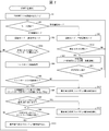
- the EMS controller 4 and the charge / discharge device 100 start the communication (S1).
- the communication determination unit 11 transmits the startup notification to the EMS controller 4 and acquires the status notification from the EMS controller 4 as a response to the startup notification, thereby completing the startup of the communication.
- the communication determination unit 11 determines whether the communication is possible (confirmation of connection with the EMS controller 4) (S2). Further, the communication determination unit 11 causes the clock unit 115 to start clocking. The above determination may be performed by any of the determination methods described above.
- the mode setting unit 12 sets the operation mode (operation mode) to the EMS control mode, and The effect is displayed on the display unit 114 (S4).
- the charge / discharge control unit 13 determines whether a predetermined time has elapsed (S5). The charge / discharge control unit 13 determines that the predetermined time has elapsed when the notification that the predetermined time has elapsed is acquired from the clock unit 115. When the charge / discharge control unit 13 determines that the predetermined time has elapsed (YES in S5), the process of S2 is performed by notifying the communication determination unit 11 to that effect.
- the charge / discharge control unit 13 determines that the predetermined time has not elapsed (if the above notification has not been acquired) (NO in S5), whether the start operation has been acquired via the input unit 113 (start) It is determined whether or not the button has been turned on), or whether an operation instruction has been obtained from the EMS controller 4 (S6).
- the process returns to S5.
- the charge / discharge control unit 13 performs an operation (an operation of charging, discharging, or standby) according to the operation instruction from the EMS controller 4 (S7).
- the charge / discharge control unit 13 determines whether a stop operation for stopping the operation has been acquired (the user has turned on the stop button) via the input unit 113 (S8). If the stop operation has been acquired (YES in S8), the charge / discharge control unit 13 notifies the communication determination unit 11 to that effect, whereby the process of S2 is performed. If the stop operation has not been acquired (NO in S8), it is determined whether a predetermined time has elapsed (S9). If the predetermined time has not elapsed (NO in S9), the process of S7 is continued. If the predetermined time has elapsed (YES in S9), charge / discharge control unit 13 notifies communication determination unit 11 to that effect.
- the communication determination unit 11 performs connection confirmation with the EMS controller 4 (S10).
- the process of S7 is performed by notifying the charge / discharge control unit 13 to that effect.
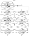
- the mode setting unit 12 performs a reserved operation from the EMS control mode as the first predetermined process. It switches to the mode and notifies the charge / discharge control unit 13 to that effect.
- the charge and discharge control unit 13 performs a reserved operation (S24).
- the mode setting unit 12 sets the operation mode to the reserved operation mode, and displays the effect on the display unit 114 (S21).
- the main body operation mode is set to the reservation operation mode.
- the mode setting unit 12 switches the EMS control mode to the reservation operation mode as the first predetermined process.
- the mode setting unit 12 As a second predetermined process, the operation mode is set to the reservation operation mode.
- the first and second predetermined processes in these cases are the same as in the flowcharts shown in FIGS. 3, 4 and 8 to 12 described later.
- the mode setting unit 12 performs EMS as the first predetermined process also when it is determined that the communication is not possible (NO in S3).
- the control mode is switched to the reserved operation mode.
- the first predetermined process in this case is the same as in the flowcharts shown in FIGS. 8 and 11 described later.
- the charge / discharge control unit 13 determines whether a predetermined time has elapsed (S22). When the charge / discharge control unit 13 determines that the predetermined time has elapsed (YES in S22), the process in S2 is performed by notifying the communication determination unit 11 to that effect. If charge / discharge control unit 13 determines that the predetermined time has not elapsed (NO in S22), the operation (charging operation or discharging operation) set in the reserved operation mode is performed via input unit 113. It is determined whether the start operation to start has been acquired (the start button has been turned on) (S23). If the start operation has not been acquired (NO in S23), the process returns to S22. If the start operation has been acquired (YES in S23), the charge / discharge control unit 13 performs reserved operation (S24).
- the charge / discharge control unit 13 determines whether a stop operation for stopping the reserved operation has been acquired (the user has turned on the stop button) via the input unit 113 (S25). If the stop operation has been acquired (YES in S25), the charge / discharge control unit 13 notifies the communication determination unit 11 to that effect, whereby the process of S2 is performed. If the stop operation has not been acquired (NO in S25), it is determined whether a predetermined time has elapsed (S26). If the predetermined time has not elapsed (NO in S26), the process of S24 is continued. When the predetermined time has elapsed (YES in S26), the communication determination unit 11 performs connection confirmation with the EMS controller 4 (S27).
- the mode setting unit 12 switches from the reserved operation mode to the EMS control mode. Then, the charge and discharge control unit 13 performs the operation according to the operation instruction from the EMS controller 4.
- the communication determination unit 11 determines that the communication is not possible (NO in S28)
- the charge / discharge control unit 13 is notified of that and the process of S24 is continued.
- the charge / discharge device 100 determines that the communication is not possible, it shifts to the reserved operation mode and performs the reserved operation. As a result, the charge / discharge device 100 can perform autonomous operation even when the communication is not possible. Therefore, it is possible to avoid a failure that may occur when the situation is reached. As the failure, for example, because the operation instruction from the EMS controller 4 can not be obtained, the battery can not be charged or discharged even if it is scheduled to be charged or discharged, or discharged until the on-board storage battery 51 becomes empty. It can be mentioned that That is, the user may not be able to perform the charging operation or the discharging operation desired.
- the charge / discharge device 100 determines that the communication is not possible from the above state, it shifts to the EMS control mode, and performs the operation according to the operation instruction from the EMS controller 4. In this case, the charge / discharge device 100 performs the operation based on the operation instruction as much as possible when the above communication is possible, thereby taking into consideration the request in the entire network to which the EMS controller 4 is connected. It becomes possible to drive.
- the charge / discharge control unit 13 determines whether the charging rate of the in-vehicle storage battery 51 has changed, and the change has occurred.
- the communication determination unit 11 may determine the state of the communication.
- the state of the communication may be determined.
- the processes of S1 to S7 of FIG. 2 are performed.
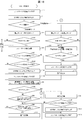
- the charge / discharge control unit 13 determines whether the charging rate of the in-vehicle storage battery 51 has changed (S31). If there is no change in the charging rate (NO in S31), the process of S7 is continued. When there is a change in the charging rate (YES in S31), the communication determination unit 11 performs connection confirmation with the EMS controller 4 (S32). When the communication determination unit 11 determines that the communication is possible (YES in S33), the process of S7 is continued. When the communication determination unit 11 determines that the communication is not possible (NO in S33), the mode setting unit 12 switches the EMS control mode to the forced charge mode as the first predetermined process. Then, the charge / discharge control unit 13 forcibly performs the charging operation regardless of the current operation state (S34).
- the charge / discharge control unit 13 determines whether the charge upper limit capacity of the in-vehicle storage battery 51 has been reached (S35). When the charging upper limit capacity is reached (YES in S35), the process in S2 is performed by notifying the communication determination unit 11 of that. If the charging upper limit capacity has not been reached (NO in S35), the charge / discharge control unit 13 continues the charging operation and determines whether the charging rate of the in-vehicle storage battery 51 has changed (S36). If there is no change in the charging rate (NO in S36), the process of S34 is continued. When there is a change in the charging rate (YES in S36), the communication determination unit 11 performs connection confirmation with the EMS controller 4 (S37).
- the process of S34 is continued.
- the mode setting unit 12 switches from the forced charging mode to the EMS control mode.
- the charge / discharge control unit 13 performs the operation based on the operation instruction from the EMS controller 4 (S7).
- the processes in S21 to S24 of FIG. 2 are performed.
- the charge and discharge control unit 13 determines whether or not there is a change in the charging rate of the on-board storage battery 51 (S41). If there is no change in the charging rate (NO in S41), the process in S24 is continued. If there is a change in the charging rate (YES in S41), the processes in S27 and S28 of FIG. 2 are performed.
- the charge / discharge device 100 determines that the above communication is disabled, the charge / discharge device 100 shifts to the forced charging mode and forcibly performs the charging operation regardless of the operation instruction of the EMS controller 4. It is also possible. As a result, it is possible to avoid a situation where the electric vehicle 5 can not be driven due to insufficient charging.
- the charging operation when performing the charging operation according to the operation instruction from the EMS controller 4, if the communication is in a disabled state, the charging operation is continued to charge up to the charging upper limit capacity of the on-board storage battery 51. Can (full charge). Moreover, when performing the discharge operation according to the operation instruction from the EMS controller 4 and when the communication is in a disabled state, the overdischarge can be avoided by switching to the charge operation.
- the charge / discharge control unit 13 may cause the communication determination unit 11 to determine the state of the communication by determining whether a predetermined time has elapsed instead of the process of S31, S36 or S41. . Also, both processes may be performed.
- ⁇ Stop of charge operation or discharge operation> an example of a process of transitioning from the EMS control mode to the reserved operation mode or to the process of stopping the charging operation or the discharging operation when it is determined that the communication is not possible. Will be explained.
- the processes of S1 to S7 and S31 to S33 of FIG. 2 are performed.
- the charge / discharge control unit 13 performs the operation performed according to the operation instruction of the EMS controller 4 as the first predetermined process. Stop (S51). Then, the charge / discharge control unit 13 notifies the communication determination unit 11 to that effect, whereby the process of S2 is performed.
- the charge / discharge device 100 again confirms the connection with the EMS controller 4, and if the communication can not be performed, it shifts to the reserved operation mode, and the communication can be performed. Then, the EMS control mode is set again. That is, when the charge / discharge device 100 determines that the communication is not possible, the operation according to the EMS controller 4 is performed or the operation is autonomously performed according to the state of the communication. You can decide what to do.
- the discharge operation when the discharge operation is performed according to the operation instruction from the EMS controller 4 and the communication can not be performed, the discharge operation can be stopped, so that overdischarge can be avoided.
- the charge / discharge device 100 notifies an abnormality in the EMS control mode when the communication is not possible.
- the mode setting unit 12 determines which operation mode, EMS control mode or reserved operation mode, to set (S61).
- the mode setting unit 12 causes the display unit 114 to display a selection image for causing the user to select the operation mode.
- the mode setting unit 12 acquires the selection operation of the user via the input unit 113, the mode setting unit 12 sets an operation mode according to the selection operation.
- the charge / discharge control unit 13 determines whether the start operation has been acquired via the input unit 113 or whether the operation instruction has been acquired from the EMS controller 4 It is determined (S63). If the start operation and the driving operation have not been acquired at any time (NO in S63), the process returns to S61. When the start operation or the driving instruction is acquired (YES in S63), the communication determination unit 11 determines whether the communication is possible (S64).
- the charge / discharge control unit 13 performs the operation according to the operation instruction from the EMS controller 4 (S66).
- the notification control unit 14 notifies that the communication is not possible as the first predetermined process. An image is displayed on the display unit 114. As a result, a notification (warning) that the communication has been disabled is issued (S67). Thereafter, the process proceeds to step S66.
- the charge / discharge device 100 when the charge / discharge device 100 is in the state in which the communication can not be performed, the charge / discharge device 100 warns that the state is in the state, but according to the operation instruction acquired from the EMS controller 4 before the communication is not possible. Continue driving.
- the communication determination unit 11 determines whether or not control information (for example, status notification or status setting notification) has been acquired from the EMS controller 4 during the operation (S68). When the control information is acquired (YES in S68), the communication determination unit 11 determines that the communication is possible. Therefore, if the warning in S67 is performed, the notification control unit 14 cancels the warning by stopping the display of the display image (S70). If the control information has not been acquired (NO in S68), the process proceeds to S69.
- control information for example, status notification or status setting notification
- the charge / discharge control unit 13 acquires, via the input unit 113, whether or not the stop operation for stopping the operation is acquired, or whether the stop instruction for stopping the operation is acquired from the EMS controller 4 It is determined whether or not it is (S69). If the stop operation and the stop instruction have not been acquired (NO in S69), the above operation is continued. If the stop operation or the stop instruction is acquired (YES in S69), the notification control unit 14 cancels the warning if the warning in S67 is performed.
- the charge / discharge control unit 13 performs the operation set in the reserved operation mode (charge operation or discharge operation) It is determined whether or not the start operation to start has been acquired (S82). If the start operation is not acquired at an arbitrary time (NO in S82), the process returns to S61. If the start operation has been acquired (YES in S81), the charge / discharge control unit 13 performs a reserved operation (S83).
- the charge / discharge control unit 13 determines whether a stop operation for stopping the operation has been acquired (S84). If the stop operation has not been acquired (NO in S84), the reserved operation is continued, and if acquired (YES in S84), the process returns to S61.
- the charge / discharge device 100 can warn when the communication is not possible, that the communication is broken. In this case, the charge / discharge device 100 can avoid a failure that may occur when the user is in the state, such as not being able to know that the user is in the state. Therefore, when the user confirms the warning, the user can determine the next process by looking at the current state of the on-board storage battery 51.
- the communication determination unit 11 performs the connection confirmation when the electric vehicle 5 is connected instead of performing the connection confirmation with the EMS controller 4 when acquiring the start operation or the driving instruction. I don't care.
- the processes of S1 to S3 of FIG. 2 are performed. If the communication determination unit 11 determines that the communication is possible in S3 (YES in S3) and the abnormal mail is transmitted in S92 or S94, the notification control unit 14 An abnormal release mail is sent (S91). When the communication determination unit 11 determines that the communication is not possible (NO in S3), the notification control unit 14 transmits the above-mentioned notification (warning) by transmitting an abnormal mail as the first predetermined process. Perform (S92).
- An abnormal e-mail is an e-mail including a sentence indicating that the communication has been disabled.
- the abnormal cancellation mail is a mail including a sentence indicating that the communication has been restored.
- the processes of S91 and S92 are performed. If it is determined in S11 that the communication is possible (YES in S11) and the abnormal mail is transmitted in S92 or S94, the notification control unit 14 transmits the abnormal cancellation mail. Send (S93). If it is determined that the communication has been disabled (NO in S11), the notification control unit 14 transmits an abnormal mail as the first predetermined process (S94).
- the notification control unit 14 performs an abnormality as the first predetermined process. It will send an email.
- the EMS control mode is on standby after the process of S3, and the process of S3 is not the connection determination in the case of YES in S5 or YES in S8, the above abnormality in the case of NO in S3. It can be said that the mail transmission process is the second predetermined process.
- the charge / discharge device 100 can perform the warning by the mail transmission even when the communication is not possible. Therefore, when the user confirms the warning, the user can determine the next process by looking at the current state of the on-board storage battery 51.
- the communication determination unit 11 determines whether the connector of the charge / discharge device 100 is connected to the charge port of the electric vehicle 5 or acquires the operation instruction from the EMS controller 4 It is determined whether or not (S63a). If it is connected to the charging port or an operation instruction is acquired at an arbitrary time (YES in S63a), the process proceeds to S64. If it is not connected to the charging port at any time, and if the operation instruction is not obtained (NO in S63a), the process proceeds to S61. In S63a, it may be determined whether or not the start operation has been acquired as in S63. Further, it may be determined whether communication with the electrically powered vehicle 5 has been started. In this case, when it is determined that the communication is started, the process proceeds to S64.
- the notification control unit 14 sets the abnormality occurrence state property as abnormality occurrence as the first predetermined process instead of S67 in FIG. 5 (S101). In the case of YES in S68 and in the case of YES in S69, the notification control unit 14 sets the abnormality occurrence state property to no abnormality occurrence, instead of S70 and S71 of FIG. 5 (S102, S103).
- the charge / discharge control unit 13 determines whether the connector of the charge / discharge device 100 is connected to the charge port of the electric vehicle 5 (S105). If it is connected to the charging port at an arbitrary time (YES in S105), the process proceeds to S83, and if it is not connected to the charging port (NO in S105), the process proceeds to S61. Note that it may be determined whether or not the start operation has been acquired as in S82. Further, it may be determined whether communication with the electrically powered vehicle 5 has been started. In this case, when it is determined that the communication has been started, the process proceeds to S83.
- the charge / discharge device 100 when the charge / discharge device 100 is in a state in which the communication can not be performed, the charge / discharge device 100 sets the abnormality occurrence state property as the occurrence of abnormality occurrence instead of the warning display. It is possible to give a warning.
- the charge / discharge device 100 of the present embodiment functions as a charging device that performs only the charging operation. Specifically, in the charge and discharge device 100 of the present embodiment, the charge and discharge circuit 111 performs only the charge operation, and the charge and discharge control unit 13 controls the charge and discharge circuit 111 that performs only the charge operation.
- the electric vehicle 5 of the present embodiment is an electric vehicle (e.g., EV or PHV) including the on-vehicle storage battery 51 dedicated to charging.
- the control target of the charge / discharge device 100 is not limited to the electric vehicle 5, and may be a storage battery dedicated to charging.
- the configuration other than the above configuration is the same as that of the power supply system 1 of the first embodiment.
- FIG. 8 is a flowchart showing an example of processing for transitioning from the EMS control mode to the reservation operation mode when it is determined that the communication is not possible as the predetermined processing.
- FIG. 9 is a flowchart showing an example of processing to shift from the EMS control mode to the reserved operation mode or the charge forcing mode in the above case.
- FIG. 10 is a flowchart showing an example of processing to shift from the EMS control mode to the reservation operation mode or to the stop processing of the charging operation or the discharging operation in the above case.
- FIGS. 8 to 10 are basically the same as the processes in FIGS. 2 to 4 except for the following points.
- the charge / discharge device 100 of the present embodiment does not perform the discharge operation. Therefore, in FIGS. 8 to 10, as the processing of the charge / discharge control unit 13 based on the EMS control mode, the charging operation or the charging operation is on standby (S7a). Similarly, only the charging operation is performed as processing of the charge / discharge control unit 13 based on the reserved operation mode (S24a).
- the charge / discharge device 100 of the present embodiment charges the on-board storage battery 51 in accordance with the operation instruction from the EMS controller 4, the charging is performed when the communication becomes impossible. Stop the operation or discharge operation. Therefore, since charging of the on-board storage battery 51 is interrupted, it is effective, for example, in a situation where charging is not desired (eg, charging fee is high or power consumption is large).
- the process of notifying an abnormality is basically the same as the process of FIGS. 5 to 7. Since the charge / discharge device 100 of the present embodiment does not perform the discharge operation, as described above, the processing of the charge / discharge control unit 13 based on the EMS control mode is a standby for the charge operation or the charge operation. Similarly, only the charging operation is performed as the process of the charge / discharge control unit 13 based on the reserved operation mode.
- the charge and discharge device 100 of the present embodiment functions as a discharge device that performs only the discharge operation. Specifically, in the charge and discharge device 100 of the present embodiment, the charge and discharge circuit 111 performs only the discharge operation, and the charge and discharge control unit 13 controls the charge and discharge circuit 111 that performs only the discharge operation.
- the electrically powered vehicle 5 of the present embodiment is an electrically powered vehicle (example: FCV) provided with the on-vehicle storage battery 51 dedicated to discharge.
- FCV electrically powered vehicle
- the control target of the charge / discharge device 100 is not limited to the electric vehicle 5, and may be various devices utilizing engine cogeneration, a fuel cell, a PV device, an FC device, or a storage battery dedicated to discharge.
- the configuration other than the above configuration is the same as that of the power supply system 1 of the first embodiment.
- FIG. 11 is a flowchart showing an example of processing to shift from the EMS control mode to the reservation operation mode when it is determined that the communication has become impossible as the predetermined processing.
- FIG. 12 is a flowchart showing an example of processing to shift from the EMS control mode to the reserved operation mode or processing for stopping the charging operation or the discharging operation in the above case.
- FIG. 11 and FIG. 12 are basically the same as the processes in FIG. 2 and FIG. 4 except for the following points.
- the charge / discharge device 100 of the present embodiment does not perform the charge operation. Therefore, in FIG. 11 and FIG. 12, as a process of the charge / discharge control unit 13 based on the EMS control mode, the discharge operation or the discharge operation is on standby (S7b). Similarly, only the discharging operation is performed as the processing of the charge / discharge control unit 13 based on the reserved operation mode (S24b).
- the charge / discharge device 100 transitions to the reserved operation mode when the communication is not possible in the state where the discharge operation is on standby in accordance with the operation instruction from the EMS controller 4 Do. Therefore, even in this case, the on-vehicle storage battery 51 can be discharged. Although the discharge can not be controlled with high accuracy as in the operation based on the EMS control mode, a peak cut effect can be obtained or power can be supplied to the device 110 or the load 120 in a time zone where the power demand is high.
- the control target of the charge / discharge device 100 of the present embodiment is effective when the FCV, various devices using engine cogeneration, or a fuel cell.
- the process of notifying an abnormality is basically the same as the process of FIGS. 5 to 7. Since the charge / discharge device 100 according to the present embodiment does not perform the charge operation, as described above, the process of the charge / discharge control unit 13 based on the EMS control mode is a discharge operation or a standby of the discharge operation. Similarly, only the discharging operation is performed as processing of the charge / discharge control unit 13 based on the reserved operation mode.
- Embodiment 4 Other embodiments of the present invention are described below.
- the control device for controlling the charge / discharge device 100 is described as being the EMS controller 4 as in the first to third embodiments, the control device is the centralized controller 7 as described in the first embodiment. It does not matter. In the case of the centralized controller 7, as described in the first embodiment, the charge / discharge device 100 may be controlled via the EMS controller 4, or the charge / discharge device 100 may be directly controlled without the EMS controller 4. I don't care.
- EMS control mode is also called “EMS operation mode.”
- movement of charge, discharge, or standby is illustrated as operation according to the driving
- the operation includes various operations (operations) other than the above, for example, a self-sustaining operation or a discharge operation in a special state in which the grid connection protection is removed.
- the connection confirmation with the EMS controller 4 may be performed again. If it is determined that the connection with the EMS controller 4 has been made in the connection check again (when it is determined that the communication with the EMS controller 4 has been resumed), the communication determination unit 11 starts up the network to which the own device is connected. Notification (instance list notification) may be performed.
- examples (A) to (D) above are given as an example of the method of determining whether the communication has not been enabled by the communication determining unit 11.
- the communication determination unit 11 determines the state notification, state setting notification (SET) or second state notification in the state in which the communication is disabled. If (ANNOUNCE) is acquired, it is determined that the communication has resumed, and a startup notification is issued.
- the communication determination unit 11 receives a response from the EMS controller 4 to the status notification performed in the state in which the communication is disabled. It is determined that the communication has resumed, and a start-up notification is issued.
- the charge / discharge device 100 notifies the EMS controller 4 of the latest state of the charge / discharge device 100 (the state at the time of resumption of communication) by notifying the start-up when the communication with the EMS controller 4 is resumed. It can be done. In the case of (D), the charge / discharge device 100 can notify the EMS controller 4 that the communication can be resumed.
- the charge / discharge control unit 13 generates the EMS controller 4 in a state in which the charge / discharge operation is “stopped” (a stop state in the charge / discharge operation), which is one of the states in which the charge / discharge operation is not performed. Indicates a state in which the driver can not accept driving instructions. In this case, the charge / discharge control unit 13 may turn off the power supply of the inverter (not shown) included in the charge / discharge circuit 111. Further, the power supply of the charge / discharge device 100 may be turned off.
- abnormality indicates that the charge / discharge device 100 or the electric vehicle 5 can not perform the charge / discharge operation because some problem occurs in the charge / discharge device 100 or the electric vehicle 5.
- the signal corresponding to pressing of the start button in the above (42) means, for example, a signal in which the status setting notification is set to "standby” in the EMS control mode or connection of the status setting notification with the electric vehicle 5 Point to the signal set in "Vehicle connection confirmation" to request confirmation.
- the charge / discharge control unit 13 generates an EMS when the charge / discharge operation is “standby” (standby state of the charge / discharge operation), which is one of the states where the charge / discharge operation is not performed. It indicates a state where it is possible to receive an operation instruction from the controller 4. In this case, the charge / discharge control unit 13 turns on the power supply of the inverter included in the charge / discharge circuit 111.
- the charging / discharging operation is in a standby state.
- the charge / discharge control unit 13 determines that the charge / discharge operation is stopped when, for example, the conditions (41) to (44) are satisfied, and turns off the power of the inverter, for example. Do. Therefore, the charge / discharge control unit 13 can not accept the operation instruction from the EMS controller 4. On the other hand, if, for example, the conditions (51) to (54) are satisfied, the charge / discharge control unit 13 determines that the charge / discharge operation is in a standby state, and turns on the power supply of the inverter. Therefore, the charge / discharge control unit 13 can receive the operation instruction from the EMS controller 4.
- stop or standby of the charge / discharge operation is merely an example.
- the process performed by the charge / discharge control unit 13 at the time of stop or standby may be set in any manner.
- the charge / discharge control unit 13 may receive an operation instruction (stop instruction) from the EMS controller 4 even if the charge / discharge operation is stopped.
- stop instruction an operation instruction
- the conditions for stopping or waiting the charge / discharge operation are not limited to the conditions of (41) to (44) or (51) to (54).
- the charge / discharge operation may be stopped (the operation instruction from the EMS controller 4 can not be received). I do not care. That is, all states when the charge and discharge operation is not performed may be stopped.
- the standby state of the charge and discharge operation (the state where the operation instruction from the EMS controller 4 is acceptable) is also possible. I do not care. That is, all the states when the charge and discharge operation is not performed may be in the standby state.
- the processing procedure described in the first embodiment is an example, as described below.
- the charge / discharge device 100 performs startup notification (instance list notification).
- the EMS controller 4 that has acquired the startup notification performs status notification (GET) to the charge / discharge device 100 that has issued the startup notification.
- the charge / discharge device 100 responds to the information indicated in the acquired status notification.
- the communication may be launched according to a processing procedure other than the above-described processing procedure (eg, a processing procedure defined by various standards).
- a processing procedure other than the above-described processing procedure eg, a processing procedure defined by various standards.
- the start-up process may be completed when the charge / discharge device 100 issues a start-up notification among the three process procedures.
- the start-up process may be completed when a signal corresponding to the start-up notification (eg, a signal notifying the presence of the own device) is transmitted. .
- the communication determination unit 11 may determine, for example, whether or not the communication is possible using the following determination method.
- the communication determination unit 11 may perform the above determination using messages such as Neighbor Solicitation and Neighbor Advertisement used in the IPv6 layer. Absent. In this case, the charge / discharge device 100 can search for the IP address and MAC address of the device (including the EMS controller 4) on the network.
- the communication determination unit 11 first performs startup notification (instance list notification), and waits for communication from the EMS controller 4 (communication corresponding to startup processing).
- the communication determination unit 11 registers the IP address of the transmission source in the storage unit as the IP address of the EMS controller 4.
- the communication determination unit 11 may determine that the communication is connected with the EMS controller 4 (the communication is possible).
- the communication determination unit 11 transmits Neighbor Solicitation by multicast.
- the communication determination unit 11 receives a Neighbor Advertisement (including an IP address and a MAC address) as a response (a response) to the transmitted Neighbor Solicitation.
- a Neighbor Advertisement including an IP address and a MAC address
- the communication determination unit 11 specifies the transmission source of the specified Neighbor Advertisement as the EMS controller 4.
- the communication determination unit 11 registers the MAC address included in the identified Neighbor Advertisement as the MAC address of the EMS controller 4 in the storage unit.
- the communication determination unit 11 transmits the Neighbor Solicitation by multicast, and when there is a response from the MAC address of the EMS controller 4, the communication determination unit 11 It determines that it is connected.
- the communication determination unit 11 first gives notification of startup and waits for communication from the EMS controller 4.
- the communication determination unit 11 registers the IP address of the transmission source in the storage unit as the IP address of the EMS controller 4.
- the communication determination unit 11 may determine that it is connected to the EMS controller 4 when the information is received.
- the communication determination unit 11 transmits an ARP request by multicast.
- the communication determination unit 11 receives an ARP reply (including an IP address and a MAC address) as a response to the transmitted ARP request.
- ARP reply including an IP address and a MAC address
- the communication determination unit 11 specifies a transmission source of the specified ARP reply as the EMS controller 4.
- the communication determination unit 11 registers the MAC address included in the identified ARP reply in the storage unit as the MAC address of the EMS controller 4.
- the communication determination unit 11 transmits the ARP request by multicast and then, when there is a response from the MAC address of the EMS controller 4, the communication determination unit 11 It determines that it is connected.
- FIGS. 13 to 18 are modified examples of the flowcharts shown in FIGS. 2 to 7. Therefore, processing different from the processing of FIGS. 2 to 7 will be mainly described, and the description of the same processing as that of FIGS. 2 to 7 will be simplified or omitted.
- the communication determination unit 11 sets the controller non-connection flag to off (S111). Thereafter, the charge / discharge device 100 starts up the communication (S1). In the present embodiment, as described above, the communication determination unit 11 transmits the startup notification to the EMS controller 4 to complete the startup of the communication.
- the controller non-connection flag is a flag indicating whether communication with the EMS controller 4 is possible.
- the controller non-connection flag is set to ON, it is assumed that the charge / discharge device 100 can not communicate with the EMS controller 4.
- the controller non-connection flag is set to off, it is assumed that the charge / discharge device 100 can communicate with the EMS controller 4.
- the controller disconnection flag is set to ON, it is possible to attempt connection confirmation with the EMS controller 4.
- the communication determination unit 11 determines whether the communication is possible (confirmation of connection with the EMS controller 4) (S2). When it is determined that the communication is possible (connection with the EMS controller 4) (YES in S3), the communication determination unit 11 determines whether the controller non-connection flag is on (S112). If it is on (YES in S112), the communication determination unit 11 sends a start-up notification to start the communication again (S113). Thereafter, the communication determination unit 11 sets the controller non-connection flag to off (S114). On the other hand, when it is off (NO in S112), the process of S113 is not performed.
- the communication determination unit 11 notifies the EMS controller 4 of the latest state of the charge / discharge device 100 when the communication is not possible but the communication is thereafter possible. Make a launch notification again. Specifically, when the communication determination unit 11 determines that the above communication is possible (YES in S3) and the controller disconnection flag is on (YES in S112), the communication determination unit 11 performs startup notification again. .
- the charge / discharge control unit 13 determines whether the predetermined time has not elapsed (NO in S5), the charge / discharge control unit 13 determines whether the start operation has been acquired via the input unit 113 (whether the start button is turned on). (S115). At this time, the charge / discharge control unit 13 may determine whether a signal corresponding to pressing of the start button has been received.
- the process returns to the process of S5.
- the charge / discharge control unit 13 performs an operation (for example, any operation of charge, discharge, or standby) according to the operation instruction from the EMS controller 4 ( S7).
- the charge / discharge device 100 shifts from the stop state of the charge / discharge operation to the standby state. Thereafter, the operation according to the above operation instruction is performed.
- the charge / discharge control unit 13 determines whether a stop operation for stopping the operation has been acquired (the user has turned on the stop button) via the input unit 113 (S8).
- the stop operation is acquired (YES in S8)
- the process of S2 is performed.
- the charge / discharge device 100 shifts to the standby state of the charge / discharge operation, and then shifts from the standby state to the halted state.
- the stop operation has not been acquired (NO in S8), the processes of S9 to S11 are performed.
- the process proceeds to the process of S21.
- the communication determination unit 11 again issues a startup notification (S117).
- the EMS controller 4 can be notified of the latest state of the charge / discharge device 100 reflecting the update that occurred while the communication was not possible but in the reserved operation mode.
- the communication determination unit 11 turns off the controller non-connection flag (S118). Thereafter, the process proceeds to the process of S7.
- the processes of S111, S1 to S3, S112 to S114, S4 to S5, S115, and S7 of FIG. 13 are performed.
- the charge / discharge control unit 13 determines whether or not the stop operation has been acquired via the input unit 113 during the above-described operation (S121). When the stop operation is acquired (YES in S121), the process of S2 is performed. If the stop operation has not been acquired (NO in S121), the processes in S31 to S33 are performed.
- the communication determination unit 11 determines that the communication is possible in S33 (YES in S33), the process of S7 is continued.
- the communication determination unit 11 turns on the controller non-connection flag (S123). Thereafter, the process proceeds to the process of S34.
- the charge / discharge device 100 shifts from the standby state to the stop state after transitioning to the standby state of the charge / discharge operation.
- the processes in S21 to S24 are performed. To be done.
- the charge / discharge control unit 13 determines whether or not the stop operation has been acquired via the input unit 113 during the above-described operation (S123). When the stop operation is acquired (YES in S123), the process of S2 is performed. If the stop operation has not been acquired (NO in S123), the processes of S41, S27 and S28 are performed.
- the communication determination unit 11 When it is determined in S28 that the communication is possible (YES in S28), the communication determination unit 11 again issues a startup notification (S117). This is because there is a high possibility that the state of the charge / discharge device 100 is changing from S3 to NO and from the shift to the reserved operation mode to the determination of YES in S28. Thereafter, the communication determination unit 11 turns off the controller non-connection flag (S118). Then, the process proceeds to the process of S7.
- FIG. 15 As the predetermined process, an example of a process of transitioning from the EMS control mode to the reserved operation mode or to the process of stopping the charging operation or the discharging operation when it is determined that the communication is not possible. Will be explained.
- the process of FIG. 15 is a modified example of the process of FIG.
- the processes of S111, S1 to S3, S112 to S114, S4 to S5, S115, S7, S121, and S31 to S33 of FIG. 14 are performed.
- the communication determination unit 11 turns on the controller non-connection flag (S131).
- the charge / discharge control unit 13 stops the operation performed in accordance with the operation instruction of the EMS controller 4 (S51). At this time, after the charge / discharge device 100 shifts to the standby state, it shifts from the standby state to the stop state. Thereafter, the process proceeds to the process of S2.
- FIGS. 16 to 18 As the predetermined process, an example of a process of notifying the abnormality when it is determined that the communication has become impossible will be described.
- the processes in FIGS. 16 to 18 are modifications of the processes in FIGS. 5 to 7, respectively.
- the communication determination unit 11 sets the controller non-connection flag to off (S111). After that, as in FIG. 5, when the communication is activated in S1, the mode setting unit 12 determines which operation mode, EMS control mode or reserved operation mode, to set (S61).
- the charge / discharge control unit 13 determines whether the start operation has been acquired via the input unit 113 (S141). If the start operation is not acquired at any time (NO in S141), the process returns to S61. If the start operation has been acquired (YES in S141), the communication determination unit 11 determines whether the communication is possible (S64). When the start operation is obtained, the charge / discharge device 100 shifts from the stop state of the charge / discharge operation to the standby state.
- the communication determination unit 11 determines that the communication is possible (YES in S65)
- the same processes as S112 to S114 in FIG. 13 are performed (S142 to S144).
- the charge / discharge control unit 13 performs the operation according to the operation instruction from the EMS controller 4 (S66).
- the communication determination unit 11 turns on the controller non-connection flag (S145). Thereafter, the notification control unit 14 notifies (warning) that the communication has been disabled (S67), and then proceeds to the processing of S66.
- the charge / discharge control unit 13 determines whether or not the stop operation has been acquired via the input unit 113 during the operation (S146). When the stop operation is acquired (YES in S146), the process of S61 is performed. If the stop operation has not been acquired (NO in S146), the processes in S68 to S71 are performed.
- the mode setting unit 12 sets the reservation operation mode by the selection of the operation mode in S61 (S81), the processing in S82 to S84 is performed.
- the reservation operation mode is selected in S81 to S84, it is assumed that communication with the EMS controller 4 is possible. This point is the same as in FIG.
- the communication determination unit 11 may set the controller non-connection flag to ON when the reservation operation mode is set. There is also a possibility that the communication can not be performed in the reservation operation mode. Even when the EMS control mode is selected in the disabled state, the EMS controller 4 can be notified of the latest state of the charge / discharge device 100 by performing start-up notification again in S143 or S148.
- the charging / discharging apparatus 100 transfers to a stop state from the said standby state, after transfering to a standby state. Thereafter, the process proceeds to the process of S2.
- the processes of S111 and S1 to S3 of FIG. 13 are performed. If the communication determination unit 11 determines that the communication is possible in S3 (YES in S3) and the abnormal mail is transmitted in S92 or S94, the notification control unit 14 An abnormal release mail is sent (S91). Thereafter, the communication determination unit 11 turns on the controller non-connection flag (S163) after the start-up is performed again (S162).
- the charge / discharge device 100 transmits the abnormality-canceling mail, when the communication becomes impossible from the above-mentioned state (when it is connected from the EMS controller 4 from the unconnected state), And make a start up notification again.
- the processes of S5, S115, and S7 to S11 are performed as in FIG.
- the communication determination unit 11 turns on the controller non-connection flag (S161). Thereafter, the notification control unit 14 performs the notification (warning) by transmitting the abnormal mail as the first predetermined process (S92). That is, the charge / discharge device 100 transmits an abnormal e-mail when the notification becomes possible from the state where the notification can be made (when the connection with the EMS controller 4 becomes the unconnected state). Thereafter, the processing of S5 and thereafter is performed.
- the communication determination unit 11 determines whether the connector of the charge / discharge device 100 is connected to the charge port of the electrically powered vehicle 5 (S141a). If it is connected to the charging port at an arbitrary time (YES in S141a), the process proceeds to S64. When the case where it does not connect to a charge port in arbitrary time is not acquired (it is NO at S141a), it transfers to S61. In S141a, it may be determined whether or not the start operation has been acquired as in S63. Further, it may be determined whether communication with the electrically powered vehicle 5 has been started. In this case, when it is determined that the communication is started, the process proceeds to S64.
- the notification control unit 14 sets the abnormality occurrence state property as abnormality occurrence as the first predetermined process, instead of S67 in FIG. 16 (S101).
- the notification control unit 14 sets the abnormality occurrence state property to no abnormality occurrence, instead of S70 and S71 of FIG. 16 (S102, S103).
- the charge / discharge control unit 13 determines whether the connector of the charge / discharge device 100 is connected to the charge port of the electrically powered vehicle 5 (S105). If it is connected to the charging port at an arbitrary time (YES in S105), the process proceeds to S83, and if it is not connected to the charging port (NO in S105), the process proceeds to S61. Note that it may be determined whether or not the start operation has been acquired as in S82. Further, it may be determined whether communication with the electrically powered vehicle 5 has been started. In this case, when it is determined that the communication has been started, the process proceeds to S83.
- the charge / discharge device 100 shifts from the stop state to the standby state.
- the start operation is acquired in S141a
- the charge / discharge device 100 shifts from the stop state of the charge / discharge operation to the standby state.
- the charge / discharge device 100 shifts to the standby state, and then shifts from the standby state to the halted state.
- the abnormality occurrence state property is a variable (internal variable) not notified to the outside of the charge / discharge device 100. Therefore, the control unit 112 does not determine whether the notification is possible (without determining the connection state between the charge / discharge device 100 and the EMS controller 4), and sets the abnormality occurrence state property to “abnormal occurrence present” or “ It may be set to “No error occurrence”.
- the charge / discharge device 100 may be a charging device that performs only the charging operation.
- the charge / discharge device 100 functions as a charge device, in S7 and S66 (processing of the charge / discharge control unit 13 based on the EMS control mode) in FIGS. 13 to 18, the charging operation or the charging operation is on standby.
- S24 and S83 of FIG. 13 to FIG. 18 processing of the charge and discharge control unit 13 based on the reservation operation mode
- the charge / discharge device 100 may be a discharge device that performs only the discharge operation.
- the charge / discharge device 100 functions as a discharge device, in S7 and S66 (processing of the charge / discharge control unit 13 based on the EMS control mode) in FIGS. 13 to 18, the discharge operation or the discharge operation is on standby.
- S24 and S83 of FIG. 13 to FIG. 18 processing of the charge and discharge control unit 13 based on the reservation operation mode
- the centralized controller 7 of the server connected to the network may control and manage the charge / discharge device 100 and the like.
- the centralized controller 7 may control the charge / discharge device 100 or the like directly without intervention of the EMS controller 4.
- the charge / discharge device 100 can be directly controlled (or managed) instead of the EMS controller 4. Therefore, in this case, the EMS controller 4 may not be provided.
- the centralized controller 7 is a host controller of the EMS controller 4. That is, although the EMS controller 4 controls and manages the charge / discharge device 100 and the plurality of devices 110 included in the power supply system 1, the centralized controller 7 includes the EMS controller 4 in addition to the charge / discharge device 100 and the plurality of devices 110. Are also controllable and manageable.
- the server provided with the centralized controller 7 is also referred to as an aggregation server.
- a charge / discharge device includes at least a charge operation for charging a storage battery with external power and a discharge operation for taking out the power stored in the storage battery and supplying the power to the outside.
- a communication unit that communicates control information with a controller that controls the charge / discharge device; a communication determination unit that determines whether the communication is enabled or not; And a process execution unit that executes a predetermined process when the communication determination unit determines that the communication is not possible.
- the charge / discharge device executes the predetermined process when it is determined that communication with the controller is not possible. Therefore, even if the above-mentioned communication can not be performed, for example, when the user can not perform the charging operation or the discharging operation desired, or can not know that the user has fallen into the state, etc. Can avoid problems that can occur in Therefore, according to the above configuration, it is possible to improve the convenience when the communication is in a disabled state.
- the predetermined process is (1) autonomous from the first control mode in which the storage battery is operated under the control of the controller without the control of the controller Alternatively, the processing may be switched to the second control mode in which the storage battery is operated, or (2) the second control mode may be set as the operation mode of the charge / discharge device.
- the failure is caused by switching to the second control mode in which the charge / discharge device operates autonomously, or by setting the operation mode to the second control mode. Can be avoided.
- the charge / discharge device can autonomously perform the processes (1) to (3).
- the predetermined process may be a process of stopping the charge operation or the discharge operation.
- the charge / discharge device stops the charging operation or the discharging operation when it can not receive control from the controller, it is possible to avoid unintended charging or discharging.
- the predetermined process may be a process of notifying that the communication is not possible.
- the communication when the communication is not possible, it is possible to notify the user that the charge / discharge device can not receive control from the controller. Therefore, when the user confirms the notification, the user can determine the next process by looking at the current state of the storage battery.
- the predetermined process can not select the first control mode for performing the operation on the storage battery under the control of the controller from the user selectable state. It may be processing to switch to.
- the first control mode when the communication is not possible, the first control mode can be made into a state in which the user can not select. Therefore, it is not necessary to cause the user to select the first control mode in a state where control from the controller can not be received. That is, the convenience of the charge and discharge device can be improved.
- the communication determination unit (1) does not receive predetermined data from the controller, or (2) a transmission connecting the charge / discharge device and the line concentrator If the link of the route is not established, it may be determined that the communication is in an impossible state.
- the state of the communication can be determined at a timing when the user desires to perform the charging operation or the discharging operation.
- the controller is a centralized controller included in a server connected to a network, and the centralized controller is a host controller of an EMS controller that controls the charge / discharge device.
- the charge / discharge device may be controlled directly without the aid of the EMS controller.
- the charge / discharge device can be directly controlled (or managed) instead of the EMS controller.
- the charge / discharge device may be realized by a computer.
- a charge / discharge program of a charge / discharge device that causes the computer to realize the charge / discharge device by operating the computer as each unit (software element) included in the charge / discharge device also falls within the scope of the present invention.
- a computer readable recording medium having the above-mentioned charge and discharge program recorded may fall within the scope of the present invention.
- control block of the charge / discharge device 100 may be realized by a logic circuit (hardware) formed in an integrated circuit (IC chip) or the like, or may be realized by software.
- the charge and discharge device 100 includes a computer that executes instructions of a program that is software that realizes each function.
- the computer includes, for example, one or more processors, and a computer readable recording medium storing the program. Then, in the computer, the processor reads the program from the recording medium and executes the program to achieve the object of the present invention.
- a CPU Central Processing Unit
- the processor reads the program from the recording medium and executes the program to achieve the object of the present invention.
- a CPU Central Processing Unit
- the processor can be used as the processor.
- a recording medium a tape, a disk, a card, a semiconductor memory, a programmable logic circuit or the like can be used besides “a non-temporary tangible medium”, for example, a ROM (Read Only Memory).
- a RAM Random Access Memory
- the program may be supplied to the computer via any transmission medium (communication network, broadcast wave, etc.) capable of transmitting the program.
- any transmission medium communication network, broadcast wave, etc.
- one aspect of the present invention can also be realized in the form of a data signal embedded in a carrier wave in which the program is embodied by electronic transmission.
Landscapes
- Engineering & Computer Science (AREA)
- Power Engineering (AREA)
- Manufacturing & Machinery (AREA)
- Chemical & Material Sciences (AREA)
- Chemical Kinetics & Catalysis (AREA)
- Electrochemistry (AREA)
- General Chemical & Material Sciences (AREA)
- Charge And Discharge Circuits For Batteries Or The Like (AREA)
Abstract
コントローラとの通信が不能な状態に陥ったときの利便性を向上させる。充放電装置(100)は、EMSコントローラ(4)との間での通信が可能な状態であるか否かを判定する通信判定部(11)と、通信が不能な状態へ陥っていると判定された場合に、所定処理を実行するモード設定部(12)、充放電制御部(13)及び通知制御部(14)と、を備える。
Description
本発明は、蓄電池に対する充電及び/又は放電を制御する装置に関する。
近年、電気自動車(EV:Electric Vehicle)、プラグインハイブリッド車(PHV:Plug in Hybrid Vehicle、PHEV:Plug-in Hybrid Electric Vehicle)、燃料電池自動車(FCV:Fuel Cell Vehicle)等の電動車両が普及している。電動車両が備える蓄電池の充電又は放電は、充放電装置により制御される。また、上記充放電装置及び家電器具等の複数の機器は、当該機器を制御するコントローラ(制御装置)に接続可能となっている。コントローラとしては、例えば、HEMS(Home Energy Management System)コントローラが挙げられる。このような電力管理システムにおける制御の一例が、特許文献1又は2に開示されている。
特許文献1の技術は、電動車両に備えられた充電装置において、電動車両の外部に設けられた充電器からの起動信号の受信が不能な状態となった場合に対処するためのものである。具体的には、充電装置は、起動信号の受信が不能な状態を通信異常として検出し、通信異常を検出すると電動車両の始動操作部がオフ操作されてから所定時間が経過するまで当該充電装置への動作用電力の供給を継続する。
また、特許文献2の技術は、余剰電力をユーザにとって都合よく活用するためのものである。具体的には、コントローラは、余剰電力が発生すると、記憶部に記憶されている電力消費スケジュールのうち、時刻を早めることが許可されたグループに分類されたスケジュールの時刻を早める。
しかし、特許文献1及び2には、HEMSコントローラ等のコントローラと、電動車両を充電するために電動車両の外部に設けられた充放電装置との間の通信状態を考慮した充放電装置の動作制御については、何ら開示されていない。特許文献1の技術では、電動車両に備えられた充電装置が、電動車両の外部に設けられた充電器(充放電装置に対応)からの起動信号を受信できるかどうかの判別を行っている。しかし、当該技術は、上記充電器と接続される上記コントローラとの通信状態を判別するものではない。
従来、上記コントローラと充放電装置との間で一旦確立された通信が途中で切断された場合、充放電装置は、上記コントローラとの通信の状態を確認できない。上記通信の切断の原因としては、例えば、上記コントローラもしくはHUBの電源オフ、又は通信ケーブルの断線が挙げられる。
この場合、充放電装置は、上記通信の切断に伴い、上記コントローラが予定している制御を受けることができなくなってしまうため、所望の充電又は放電を行うことができない。また、充放電装置は、切断前の上記コントローラからの運転指示に基づく動作を継続することになる。例えば、上記運転指示が放電動作を行う旨の指示である場合、蓄電池の電池残量が無くなってしまう。
つまり、従来の技術では、上記通信の切断を考慮していないため、充放電装置が所望の充電又は放電を行うことができない可能性がある。
本発明の一態様は、コントローラとの通信が不能な状態に陥ったときの利便性を向上させることが可能な充放電装置を実現することを目的とする。
上記の課題を解決するために、本発明の一態様に係る充放電装置は、外部の電力により蓄電池を充電する充電動作、及び上記蓄電池に蓄積された電力を取り出し外部へ供給する放電動作の少なくとも一方を行う充放電装置であって、上記充放電装置を制御するコントローラとの間で制御情報の通信を行う通信部と、上記通信が可能な状態であるか否かを判定する通信判定部と、上記通信が不能な状態へ陥っていると上記通信判定部が判定した場合に、所定処理を実行する処理実行部と、を備える。
本発明の一態様によれば、上記通信が不能な状態に陥ったときの利便性を向上させることができるという効果を奏する。
本発明の一態様に係る充放電装置について、以下の各実施形態において説明する。なお、特許請求の範囲に係る充放電装置は、充電動作及び放電動作の両方を行うことが可能な充放電装置(実施形態1参照)、充電動作のみを行う充電装置(実施形態2参照)、並びに、放電動作のみを行う放電装置(実施形態3参照)のいずれかの装置を指す。つまり、特許請求の範囲に係る充放電装置は、充放電装置、充電装置及び放電装置を含む概念である。
〔実施形態1〕
以下、本発明の実施の形態について、詳細に説明する。
以下、本発明の実施の形態について、詳細に説明する。
≪電力供給システム1≫
図1は、本発明の一実施形態に係る充放電装置100を含む電力供給システム1の概略構成図である。電力供給システム1は、例えば、商用電力系統2(商用系統)と、分電盤3と、EMS(Energy Management System)コントローラ4と、電動車両5と、HUB6(集線装置)と、充放電装置100と、複数の機器110と、複数の負荷120と、を含む。
図1は、本発明の一実施形態に係る充放電装置100を含む電力供給システム1の概略構成図である。電力供給システム1は、例えば、商用電力系統2(商用系統)と、分電盤3と、EMS(Energy Management System)コントローラ4と、電動車両5と、HUB6(集線装置)と、充放電装置100と、複数の機器110と、複数の負荷120と、を含む。
商用電力系統2は、電力会社からの電力系統である。電力系統は電力を供給するための、発電・変電・送電及び配電を統合したシステムである。
分電盤3は、商用電力系統2に接続される。商用電力系統2から分電盤3に規定の電圧(100V/200V)の商用交流電力が供給される。交流電力は、分電盤3を通じて、充放電装置100、複数の機器110及び複数の負荷120に供給される。充放電装置100等は、分電盤3を通じて供給される交流電力(または交流電力から変換された直流電力)を用いて動作する。
また、分電盤3は、主幹ブレーカ(図示省略)を含む。主幹ブレーカは、分電盤3内の母線に設けられており、母線を構成する3相の配線(3相3線式)の導通および非導通を切り替えるために用いられる。なお、主幹ブレーカの配線形態は、3相3線式に限らず、例えば、単相3線式又は単相2線式であっても構わない。さらに、分電盤3は、各種の電力を計測するためのセンサ(図示省略)を含む。なお、商用電力系統2と分電盤3との間に設けられたスマートメータ(図示省略)が、センサが検知した電力の情報をEMSコントローラ4に通知する構成であっても構わない。
EMSコントローラ4は、主として、充放電装置100及び複数の機器110を、制御及び管理するコントローラ(制御装置)である。具体的には、EMSコントローラ4は、充放電装置100及び複数の機器110に、通信ケーブル(例:LAN(Local Area Network)ケーブル)を介して接続される。EMSコントローラ4は、充放電装置100及び複数の機器110の各動作モードを制御する。
なお、ネットワークに接続されたサーバの集中コントローラ7が、充放電装置100等を制御及び管理しても構わない。例えば、集中コントローラ7は、充電もしくは放電動作に関する指示、又は、充電量もしくは放電量に関する指示をEMSコントローラ4に送信することで、EMSコントローラ4に充放電装置100等を制御及び管理させる。つまり、集中コントローラ7から充放電装置100等への指示は、EMSコントローラ4を経由して行われる。この場合、集中コントローラ7とEMSコントローラ4との間の通信は、後述のECHONETLite(登録商標)規格に基づく通信であるとは限らない。但し、集中コントローラ7が後述のECHONETLite規格に対応する機器である場合には、EMSコントローラ4に代わり集中コントローラ7が、充放電装置100等を直接制御及び管理することが可能である。充放電装置100等は、EMSコントローラ4からの指示であるか、ネットワークを通じて別のコントローラ(例:集中コントローラ7)からの指示であるかを、当該指示に含まれる「遠隔操作設定」プロパティの設定(公衆回線経由・未経由)によって識別する。
また、電力供給システム1が家庭用として用いられる場合、EMSコントローラ4はHEMSコントローラとして機能する。電力供給システム1がビル用として用いられる場合、EMSコントローラ4はBEMS(Building Energy Management System)コントローラとして機能する。電力供給システム1が工場用として用いられる場合、EMSコントローラ4はFEMS(Factory Energy Management System)コントローラとして機能する。電力供給システム1が地域用として用いられる場合、EMSコントローラ4はCEMS(Community Energy Management System)コントローラとして機能する。但し、EMSコントローラ4は、主として、充放電装置100及び複数の機器110を、制御及び管理するコントローラ(制御装置)であればよく、上記各コントローラに限られない。
EMSコントローラ4は、ネットワークを介して各種サーバと接続される。各種サーバは、例えば、商用電力系統2から供給を受ける電力の購入単価、商用電力系統2に対して供給する電力の売却単価、及び燃料ガスの購入単価などの情報を格納する。
電動車両5は、走行時に用いられる電力を蓄えるための大容量の車載蓄電池51(蓄電池)を搭載する。商用電力系統2の停電時、車載蓄電池51内の電力は、充放電装置100により、複数の機器110及び複数の負荷120に供給される。電動車両5は、駆動用の蓄電池を搭載しており、当該蓄電池内の電力を駆動力に変換して走行可能な各種の車両を含む。当該車両としては、例えば、電気自動車(EV:Electric Vehicle)、プラグインハイブリッド車(PHV:Plug in Hybrid Vehicle、PHEV:Plug-in Hybrid Electric Vehicle)、又は燃料電池自動車(FCV:Fuel Cell Vehicle)が挙げられる。充放電装置100の制御対象は、電動車両5でなくてもよく、例えば、充放電可能な蓄電池でも構わない。また、後述の実施形態2及び3に例示する制御対象であっても構わない。
なお、上記停電時の電力供給処理は、特に、充放電装置100の自立運転と称される。一方、非停電時にも、車載蓄電池51内の電力を、複数の機器110等に供給できる。この場合、商用電力系統2及び充放電装置100の双方から複数の機器110等へ、交流電力が供給される。この非停電時の電力供給処理は、特に、充放電装置100の系統連系運転と称される。
複数の機器110は、通信機能を備えた機器であり、例えばエアコン、 冷蔵庫又はIH(Induction Heating)クッキングヒータなどである。また、複数の負荷120は、例
えば、コンセントに接続される負荷機器である。なお、どのような負荷機器がコンセントに接続されるかは不定である。
えば、コンセントに接続される負荷機器である。なお、どのような負荷機器がコンセントに接続されるかは不定である。
なお、電力供給システム1は、EMSコントローラ4の制御対象として、太陽光の受光に応じて発電を行うPV(太陽光発電)装置、及び/又は、燃料(ガス)を用いて電力を発電するFC(燃料電池)装置を含んでも構わない。PV装置及びFC装置は、発電機器の一例である。PV装置及びFC装置は、自立運転時、充放電装置100から供給される交流電力を用いて動作し、系統連系運転することも可能である。
また、電力供給システム1は、HUB6と接続されたルータ(図示省略)を含む。ルータは、ネットワークに接続されたサーバ等と、EMSコントローラ4、充放電装置100及び複数の機器110との通信接続を可能とする。ルータは、特に、上記集中コントローラ7が充放電装置100等を制御及び管理する場合には、必要となる構成である。なお、本実施形態のルータが、EMSコントローラ4の機能を有していても構わない。
ここで、EMSコントローラ4と各機器(主として、充放電装置100及び複数の機器110)とは、HUB6を介して接続される。EMSコントローラ4と充放電装置100及び複数の機器110との間の通信は、所定のプロトコルに従った方式で行われる。所定のプロトコルとしては、例えば、ECHONETLiteまたはECHONET(登録商標)と呼ばれるプロトコルが挙げられ、この場合、充放電装置100及び複数の機器110は、ECHONETLite規格またはECHONET規格に対応する機器である。もちろん、所定のプロトコルは、ECHONETLite及びECHONET以外のプロトコルであっても構わない。なお、複数の負荷120は、ECHONETLite規格またはECHONET規格に対応する機器ではなく、EMSコントローラ4と通信を行うものではない。
なお、本実施形態の電力供給システム1では、HUB6を介して、EMSコントローラ4と充放電装置100等の機器とが接続されるものとして説明する。しかし、電力供給システム1がHUB6を備えている必要は必ずしもない。この場合、EMSコントローラ4と充放電装置100等の機器とは1対1の直接的な通信を行う。
以下では、所定のプロトコルをECHONETLiteとし、充放電装置100及び複数の機器110をECHONETLite規格に対応する機器とする例を用いて説明する。
≪充放電装置≫
図1に示すように、充放電装置100は、主として、充放電回路111と、制御部112と、入力部113と、表示部114と、計時部115と、通信部116とを備える。充放電装置100は、商用電力系統2から電動車両5に搭載された車載蓄電池51への充電、及び、電動車両5の車載蓄電池51から複数の機器110及び複数の負荷120への電力供給の双方に用いられる。つまり、充放電装置100は、外部の電力により車載蓄電池51を充電する充電動作、及び車載蓄電池51に蓄積された電力を取り出し外部へ供給する放電動作の両方を行う。また、充放電装置100は、HUB6を介して、EMSコントローラ4と制御情報の通信を行うことが可能である。
図1に示すように、充放電装置100は、主として、充放電回路111と、制御部112と、入力部113と、表示部114と、計時部115と、通信部116とを備える。充放電装置100は、商用電力系統2から電動車両5に搭載された車載蓄電池51への充電、及び、電動車両5の車載蓄電池51から複数の機器110及び複数の負荷120への電力供給の双方に用いられる。つまり、充放電装置100は、外部の電力により車載蓄電池51を充電する充電動作、及び車載蓄電池51に蓄積された電力を取り出し外部へ供給する放電動作の両方を行う。また、充放電装置100は、HUB6を介して、EMSコントローラ4と制御情報の通信を行うことが可能である。
充放電回路111は、車載蓄電池51を充電する(充電運転)。また、充放電回路111は、自立運転時又は系統連系運転時、車載蓄電池51から直流電力を取り出す。充放電回路111は、車載蓄電池51から取り出した直流電力を、所定電圧の交流電力に変換し、複数の機器110及び複数の負荷120に供給する。複数の機器110及び複数の負荷120は、充放電装置100から供給される交流電力を用いて動作する。
制御部112は、充放電装置100の動作(例:充電及び放電)を統括的に制御する。制御部112は、主として、通信判定部11、モード設定部12、充放電制御部13及び通知制御部14を備える。
通信判定部11は、EMSコントローラ4との通信(ECHONETLite通信)が可能な状態であるか否かを判定する。本実施形態では、通信判定部11は、充放電装置100のネットワーク参入時の上記通信の立ち上げ後に、上記通信が不能な状態に陥っていないかの判定を行う。上記通信が不能な状態へ陥っていないか否かの判定手法としては、例えば以下の(A)~(D)が挙げられる。
(A)立ち上げ時の手順に従った通信判定
通信判定部11は、ECHONETLite通信の立ち上げ時以外のときに、規格で定められた当該立ち上げ時の所定の手順に従った処理を行うことで、上記判定を行う。上記立ち上げ時には以下の処理が行われる。なお、上記立ち上げとは、EMSコントローラ4が存在するネットワークに充放電装置100が参入したときの、EMSコントローラ4と充放電装置100との間での通信を可能とするための処理を指す。
通信判定部11は、ECHONETLite通信の立ち上げ時以外のときに、規格で定められた当該立ち上げ時の所定の手順に従った処理を行うことで、上記判定を行う。上記立ち上げ時には以下の処理が行われる。なお、上記立ち上げとは、EMSコントローラ4が存在するネットワークに充放電装置100が参入したときの、EMSコントローラ4と充放電装置100との間での通信を可能とするための処理を指す。
上記立ち上げ時には、充放電装置100では、まず、制御部112(本実施形態では通信判定部11)は、自装置が接続されるネットワークに対して、自装置の存在を通知する立ち上げ通知(インスタンスリスト通知)を行う。ネットワーク上のEMSコントローラ4は、立ち上げ通知を取得すると、充放電装置100に対して、充放電装置100の状態に関する情報の通知を要求する状態通知(GET)を行う。制御部112は、状態通知を取得すると、状態通知に示された情報(プロパティ値)をEMSコントローラ4に返答する。すなわち、上記状態通知は、充放電装置100等の機器に対して、プロパティ又はプロパティ値をEMSコントローラ4に(ユニキャストで)通信するための要求を行うことともいえる。
つまり、通信判定部11は、立ち上げ時以外のときに立ち上げ通知を行い、それに対する状態通知をEMSコントローラ4から取得した場合に、EMSコントローラ4から通信があったものと判定する。換言すれば、通信判定部11は、この場合に、EMSコントローラ4との通信が可能である(EMSコントローラ4との通信状態が維持されている)と判定する。一方、通信判定部11は、立ち上げ通知に対する状態通知を取得しなかった場合に、上記通信が不能な状態に陥ったと判定する。
また、通信判定部11は、状態通知の取得時に、EMSコントローラ4のIP(Internet Protocol)アドレス又はMAC(Media Access Control)アドレスを取得して、自装置が備える記憶部(不図示)に格納する。通信判定部11は、立ち上げ時以外に取得したIPアドレス又はMACアドレスが、立ち上げ時に取得したIPアドレス又はMACアドレスと一致するか否かを判定しても構わない。この場合、通信判定部11は、一致した場合に上記通信が可能な状態と判定し、一致しなかった場合には上記通信が不能な状態に陥ったと判定する。
(B)状態通知又は状態設定通知を用いた通信判定
通信判定部11は、予め定められた時間内に、EMSコントローラ4から状態通知又は状態設定通知(SET)を取得した場合には、上記通信が可能な状態であると判定する。通信判定部11は、状態通知又は状態設定通知を取得しなかった場合には、上記通信が不能な状態に陥ったと判定する。
通信判定部11は、予め定められた時間内に、EMSコントローラ4から状態通知又は状態設定通知(SET)を取得した場合には、上記通信が可能な状態であると判定する。通信判定部11は、状態通知又は状態設定通知を取得しなかった場合には、上記通信が不能な状態に陥ったと判定する。
上記立ち上げ時には、EMSコントローラ4は、充放電装置100から状態通知に対する返答を受けると、充放電装置100の状態に関する情報(プロパティ値)の設定又は変更を要求する状態設定通知を行う。制御部112は、状態設定通知を受け取ると、当該状態設定通知に基づき、自装置の上記情報を設定又は変更する。すなわち、状態設定通知は、充放電装置100等の機器に対して、プロパティ又はプロパティ値を設定するための要求を行うことともいえる。
ここで、EMSコントローラ4は、立ち上げ時以外にも、予め定められた時間毎に、状態通知又は状態設定通知を行うものが多いと考えられる。例えば、EMSコントローラ4側での画像表示又はログ収集のために、定期的に状態通知を行っているものと考えられるためである。このようなEMSコントローラ4と通信可能か否かの判定において、上述のように状態通知又は状態設定通知を取得したか否かを判定することは有用である。
なお、上記では、状態通知(GET)又は状態設定通知(SET)の取得可否により上記通信が可能な状態であるか否かの判定が行われる例について説明した。これに限らず、通信判定部11は、状態通知又は状態設定通知以外の情報の取得可否により、上記判定を行っても構わない。例えば、通信判定部11は、予め定められた時間内に、第2状態通知(ANNOUNCE)を取得した場合に、上記通信が可能な状態であると判定する。第2状態通知とは、充放電装置100等の機器に対して、プロパティ又はプロパティ値をネットワーク全体に(マルチキャストで)通信するための要求を行うことをいう。
(C)状態通知に対する返答有無に基づく通信判定
通信判定部11は、EMSコントローラ4に対して、EMSコントローラ4の状態に関する情報の通知を要求する状態通知(GET)を行う。通信判定部11は、状態通知に対してEMSコントローラ4から返答があった場合には、上記通信が可能な状態であると判定し、返答が無かった場合には、上記通信が不能な状態に陥ったと判定する。
通信判定部11は、EMSコントローラ4に対して、EMSコントローラ4の状態に関する情報の通知を要求する状態通知(GET)を行う。通信判定部11は、状態通知に対してEMSコントローラ4から返答があった場合には、上記通信が可能な状態であると判定し、返答が無かった場合には、上記通信が不能な状態に陥ったと判定する。
なお、上記返答としては、状態通知の要求通りに動作することを返答する「応答」と、状態通知を受け取ったが、状態通知の要求通りには動作しないことを返答する「不可応答」とがある。
(D)通信ケーブルのリンクの確立有無に基づく通信判定
通信判定部11は、充放電装置100が通信ケーブルに接続されているか否か、及び通信ケーブルが接続されているHUB6(又はHUB6を介して接続される相手機器)と通信可能な状態か否かを判定する。つまり、通信判定部11は、通信ケーブルのリンクが確立しているか否かを判定する。通信判定部11は、リンクが確立している場合には、上記通信が可能な状態であると判定し、リンクが確立していない場合には、上記通信が不能な状態に陥ったと判定する。
通信判定部11は、充放電装置100が通信ケーブルに接続されているか否か、及び通信ケーブルが接続されているHUB6(又はHUB6を介して接続される相手機器)と通信可能な状態か否かを判定する。つまり、通信判定部11は、通信ケーブルのリンクが確立しているか否かを判定する。通信判定部11は、リンクが確立している場合には、上記通信が可能な状態であると判定し、リンクが確立していない場合には、上記通信が不能な状態に陥ったと判定する。
なお、リンクが確立されている場合には、通信ポート(例:LANポート)のアクティブリンクLED(Light Emitting Diode)が点滅する。また、通信判定部11は、リンクが確立している場合に上記通信が可能な状態であると判定するが、通信ケーブルを介して接続される相手機器までは特定できない。そのため、リンクが確立されている場合でも上記通信が可能な状態とは限らない。しかし、本実施形態では、リンクが確立されていれば、上記通信が可能な状態であると判定する。
上記(A)~(D)の処理を纏めると、通信判定部11は、
(1)EMSコントローラ4から、所定のデータとして、状態通知(立ち上げ通知に対する返答としての状態通知を含む)、第2状態通知又は状態設定通知を受信しない場合、又は、
(2)充放電装置100とHUB6とを結ぶ通信ケーブルのリンクが確立されていない場合に、
上記通信が不能な状態に陥っていると判定する。
(1)EMSコントローラ4から、所定のデータとして、状態通知(立ち上げ通知に対する返答としての状態通知を含む)、第2状態通知又は状態設定通知を受信しない場合、又は、
(2)充放電装置100とHUB6とを結ぶ通信ケーブルのリンクが確立されていない場合に、
上記通信が不能な状態に陥っていると判定する。
なお、本実施形態では、充放電装置100等の各種装置とHUB6とを結ぶ伝送路が通信ケーブル(有線)である場合を例に挙げて説明するが、これに限らず、当該伝送路は無線であっても構わない。
また、通信判定部11は、
(11)所定時間毎に、
(12)車載蓄電池51の充電率(SOC:State of Charge)が変化したときに、
(13)電動車両5が接続されたときに、又は、
(14)EMS制御モード(後述)での制御を開始する開始操作を取得したときに、
上記通信が不能な状態へ陥っているか否かの判定を行う。
(11)所定時間毎に、
(12)車載蓄電池51の充電率(SOC:State of Charge)が変化したときに、
(13)電動車両5が接続されたときに、又は、
(14)EMS制御モード(後述)での制御を開始する開始操作を取得したときに、
上記通信が不能な状態へ陥っているか否かの判定を行う。
上記(13)の「電動車両5が接続された」とは、例えば、充放電装置100のコネクタが電動車両5の充電口に接続されたこと、又は、電動車両5との通信が開始されたことを指す。また、上記(14)の「開始操作」は、例えば、入力部113を介して、ユーザが上記制御を開始させるためのスタートボタンをオンすることによって実現される。
なお、上記判定を行うタイミングは、上記(11)~(14)のタイミングに限らず、充放電装置100の停止中、運転中、電動車両5と接続中、又は、充電動作もしくは放電動作の待機中のいずれかの状態における任意のタイミングで行われて構わない。また、上記通信の状態の判定は、上記通信が不能な状態に陥っていると判定されてからも継続して行われても構わない。
なお、上述した判定手法及びタイミングのうち、どの判定手法で、かつどのタイミングで上記判定を行うか否かについては、予め設定されていても構わない。その他、接続された電動車両5の種類(車載蓄電池51の種類)によって、又はユーザ操作によって設定されても構わない。
モード設定部12、充放電制御部13及び通知制御部14は、上記通信が不能な状態へ陥っていると通信判定部11が判定した場合に、所定処理を実行する処理実行部として機能する。所定処理とは、上記通信が不能な状態に陥ったと判定されたときに実行すべき処理として予め定められた処理である。所定処理には、EMSコントローラ4による制御を受けられる状態から受けられない状態へと変化したときに実行すべき処理として予め定められた処理(第1所定処理とも称する)が含まれる。なお、所定処理のうち、第1所定処理とは異なる処理を第2所定処理とも称する。
モード設定部12は、充放電装置100の動作モードを、EMS制御モード(第1制御モード)と本体動作モード(第2制御モード)とのいずれかに設定する。EMS制御モードは、EMSコントローラ4の制御を受けて車載蓄電池51に対する動作を行うモードである。本体動作モードは、EMSコントローラ4の制御を受けずに自律的に車載蓄電池51に対する動作を行うモードである。なお、EMS制御モードは、ECHONETLite規格における各種指示を受け取り可能な動作モードともいえる。
モード設定部12は、上記通信が不能な状態に陥ったと判定された場合に、上記所定処理として、EMS制御モードを本体動作モードに切り替える処理、又は動作モードを本体動作モードに設定する処理を行う。また、モード設定部12は、上記所定処理として、ユーザ選択可能な状態からユーザ選択不可能な状態へと切り替える処理を行っても構わない。この場合、モード設定部12は、EMS制御モードを選択するユーザ操作を受け付けることができないような動作モードの選択画像を、表示部114に表示する。
また、モード設定部12は、入力部113を介して取得したユーザ操作に従い、EMS制御モード又は本体動作モードを設定しても構わない。
充放電制御部13は、充放電回路111を制御して、車載蓄電池51への充電動作又は放電動作を制御する。
充放電制御部13は、EMS制御モードに設定されている場合、EMSコントローラ4からの運転指示に従い、車載蓄電池51の充電動作又は放電動作を開始すると共に、これらの動作を停止する。また、充放電制御部13は、当該運転指示に従い、充電動作又は放電動作の開始を待機する。
充放電制御部13は、上記所定処理として、EMS制御モードから本体動作モードに切り替えられた場合に、
(21)充放電装置100に設定された充電時刻又は放電時刻に従って、車載蓄電池51に対する充電動作又は放電動作を行うか、
(22)EMS制御モードでのEMSコントローラ4の制御内容(運転指示)に依らず、車載蓄電池51の充電上限容量まで充電を行うか、
(23)直前のEMS制御モードで行っていた車載蓄電池51に対する充電動作もしくは放電動作を継続する。
(21)充放電装置100に設定された充電時刻又は放電時刻に従って、車載蓄電池51に対する充電動作又は放電動作を行うか、
(22)EMS制御モードでのEMSコントローラ4の制御内容(運転指示)に依らず、車載蓄電池51の充電上限容量まで充電を行うか、
(23)直前のEMS制御モードで行っていた車載蓄電池51に対する充電動作もしくは放電動作を継続する。
上記(21)の場合、本体動作モードは予約運転モードと称しても構わない。具体的には、予約運転モードは、充放電装置100において予め設定された予約時刻(開始時刻および終了時刻)に従って、充電動作又は放電動作が行われるモードである。充電動作及び放電動作のいずれが行われるかについても、予め設定されている。予約運転モードにおける充電動作又は放電動作は、予約運転と称しても構わない。
なお、充放電装置100の制御対象が、予約運転ができない電動車両5(例:PV又はFCV)の場合、電動車両5に予約運転を行わせることができない。そのため、当該電動車両5の場合には、上記(21)に代えて、上記(23)の処理が行われる。上記(23)の場合、本体動作モードは動作継続モードと称しても構わない。
また、EMSコントローラ4及び充放電装置100は、予約運転モード時に、ECHONETLite通信を行うことが可能な仕様であっても構わない。但し、この場合、EMSコントローラ4は、状態通知を行うことは可能であるが、状態設定通知を行うことはできない(充放電装置100は、状態設定通知に対して不可応答を返答する)。また、予約運転中にECHONETLite通信が確立した場合に(上記通信が不能な状態から可能な状態になったと通信判定部11が判定した場合に)、予約運転モードからEMS制御モードへと移行しても構わない。
上記(22)の場合、本体動作モードは、強制的に充電動作を行う強制充電モードと称しても構わない。つまり、上記制御内容が充放電装置100に充電動作を行わせるものであれば、そのまま充電動作が継続される。上記制御内容が充放電装置100に放電動作を行わせるもの、又は、充電動作もしくは放電動作を待機させるものであれば、充電動作に切り替えられる。
なお、上記(22)の場合において、充電上限容量まで充電が行われる必要はなく、予め定められた容量まで充電されればよい。本実施形態では、充電上限容量まで充電が行われるものとして説明する。
充放電制御部13は、上記所定処理として本体動作モードへと切り替えられた場合に、上記(21)~(23)のいずれかの処理を行う。つまり、本体動作モードは、上記(21)~(23)のいずれかを行うモードであるといえる。
また、充放電制御部13は、上記所定処理として、上記充電動作又は放電動作を停止する。
なお、本体動作モードへの切り替え、及び上記停止する処理のいずれの処理を行うか、また、本体動作モードへ切り替えられた場合に上記(21)~(23)のいずれの処理を行うかについては、予め設定されていても構わない。その他、接続された電動車両5の種類(車載蓄電池51の種類)によって、又はユーザ操作によって設定されても構わない。
通知制御部14は、上記所定処理として、上記通信が不能な状態へ陥っていることを示す通知(異常の通知)を行うものである。通知制御部14は、以下の(31)~(34)の少なくともいずれかの方法で、上記通知を行う。これらの処理のいずれで上記通知を行うかは、予め設定されていても構わない。
(31)異常を示す表示画像を表示部114に表示する。異常を表示ではなく、音により通知しても構わない。異常を、表示及び音で通知しても構わない。
(32)充放電装置100が通信可能な、ECHONETLite規格に対応する機器以外の外部機器(例:スマートフォン又はタブレット等の携帯型情報端末)に、上記表示画像を表示する。この場合、当該外部機器には、例えば、異常を知らせるアプリケーションがインストールされている。上記(31)と同様、異常を音により通知しても構わない。
(33)EMSコントローラ4又は上記外部機器に、異常を示す文面が記載されたメールの送信を行う。EMSコントローラ4にメールが送信される場合、上記通信が可能となった場合に行われる。
(34)異常発生状態プロパティを異常発生有りに設定する。異常発生状態プロパティは、ECHONETLite規格のスーパークラス(ECHONETLite規格対応の装置が全て含まれるクラス)において準備されているものである。異常発生有りの異常発生状態プロパティは、上記通信が可能となった場合に、EMSコントローラ4に通知される。
なお、上記所定処理としては、いずれかの処理が行われればよい。但し、本体動作モードに基づく処理、又は充電動作もしくは放電動作の停止処理が行われるとともに、上記通知の処理が行われても構わない。
入力部113は、ユーザ操作を受け付けて、入力された内容を制御部112に出力する。表示部114は、制御部112の制御下で、各種の表示を行う。入力部113及び表示部114は、タッチパネルとして一体化されていてもよい。
計時部115は、制御部112の制御下で、予め設定された時間を計時する。計時部115は、例えば、通信判定部11が上記通信の状態を判定した時点からの所定時間を計時する。
通信部116は、制御部112の制御下で、EMSコントローラ4との間で制御情報の通信を行う。制御情報としては、例えば、上述した立ち上げ通知、状態通知、第2状態通知及び状態設定通知を示す情報(及び、これらの通知に含まれる情報(例:プロパティ値))が挙げられる。EMSコントローラ4から送信される当該情報には、充放電装置100の充電動作もしくは放電動作の開始もしくは停止の指示、又はこれらの動作の待機の指示を示す運転指示も含まれる。また、充放電装置100が上記外部機器と通信が可能な場合、通信部116は、当該外部機器との通信を行う。
≪各種処理の流れ≫
次に、充放電装置100における処理の一例について説明する。以下の処理において、予約運転モードを動作継続モードに代えてもよい。
次に、充放電装置100における処理の一例について説明する。以下の処理において、予約運転モードを動作継続モードに代えてもよい。
<本体運転モード(予約運転)へ移行する場合>
図2を参照して、上記所定処理として、上記通信が不能に陥ったと判定された場合に、EMS制御モードから本体動作モード(予約運転モード)へ移行する処理の一例について説明する。
図2を参照して、上記所定処理として、上記通信が不能に陥ったと判定された場合に、EMS制御モードから本体動作モード(予約運転モード)へ移行する処理の一例について説明する。
図2に示すように、充放電装置100の電源がオンすると、EMSコントローラ4及び充放電装置100は、上記通信を立ち上げる(S1)。上述のように、通信判定部11は、立ち上げ通知をEMSコントローラ4に送信し、立ち上げ通知に対する返答として、EMSコントローラ4から状態通知を取得することで、上記通信の立ち上げが完了する。
上記立ち上げが完了すると、通信判定部11は、上記通信が可能な状態であるか否かの判定(EMSコントローラ4との接続確認)を行う(S2)。また、通信判定部11は、計時部115に計時を開始させる。なお、上記判定は、上述した判定手法のいずれで行われても構わない。
上記通信が可能な状態である(EMSコントローラ4と接続有り)と通信判定部11が判定した場合(S3でYES)、モード設定部12は、動作モード(運転モード)をEMS制御モードとし、その旨を表示部114に表示する(S4)。
充放電制御部13は、所定時間が経過した否かを判定する(S5)。充放電制御部13は、計時部115から所定時間経過した旨の通知を取得した場合に、所定時間が経過したと判定する。充放電制御部13は、所定時間が経過したと判定した場合には(S5でYES)、通信判定部11にその旨を通知することで、S2の処理が行われる。充放電制御部13は、所定時間が経過していないと判定した場合(上記通知を取得していない場合)には(S5でNO)、入力部113を介して開始操作を取得したか(スタートボタンがオンされたか)否か、又はEMSコントローラ4から運転指示を取得したか否かを判定する(S6)。
充放電制御部13は、開始操作及び運転指示を取得していない場合には(S6でNO)、S5の処理に戻る。開始操作又は運転指示を取得した場合には(S6でYES)、充放電制御部13は、EMSコントローラ4からの運転指示に従った運転(充電、放電、又は待機のいずれかの動作)を行う(S7)。
充放電制御部13は、上記運転中に、入力部113を介して、上記運転を停止する停止操作を取得(ユーザがストップボタンをオン)したか否かを判定している(S8)。停止操作を取得した場合(S8でYES)、充放電制御部13は、その旨を通信判定部11に通知することで、S2の処理が行われる。停止操作を取得していない場合には(S8でNO)、所定時間が経過したか否かを判定する(S9)。所定時間が経過していなければ(S9でNO)、S7の処理が継続される。所定時間が経過した場合には(S9でYES)、充放電制御部13は、その旨を通信判定部11に通知する。この場合、通信判定部11は、EMSコントローラ4との接続確認を行う(S10)。通信判定部11は、上記通信が可能な状態であると判定した場合(S11でYES)、充放電制御部13にその旨を通知することで、S7の処理が行われる。上記通信が不能な状態に陥った(EMSコントローラ4と接続無し)と通信判定部11が判定した場合(S11でNO)、モード設定部12は、上記第1所定処理としてEMS制御モードから予約運転モードに切り替え、その旨を充放電制御部13に通知する。充放電制御部13は、予約運転を行う(S24)。
S3で上記通信が不能な状態に陥ったと判定された場合(S3でNO)、モード設定部12は、動作モードを予約運転モードとし、その旨を表示部114に表示する(S21)。本実施形態では、本体運転モードが予約運転モードに設定されているものとする。
なお、S4でEMS制御モードに設定され、所定時間経過後に(S5でYES)再度、EMSコントローラ4との接続確認の結果、上記通信が不能な状態に陥ったと判定された場合(S3でNO)、モード設定部12は、上記第1所定処理としてEMS制御モードから予約運転モードに切り替えることとなる。一方、S1で上記通信を立ち上げた後、S4でEMS制御モードに設定される前に、上記通信が不能な状態に陥ったと判定された場合(S3でNO)、モード設定部12は、上記第2所定処理として、動作モードを予約運転モードに設定する。これらの場合の上記第1及び第2所定処理は、後述の図3、図4及び図8~図12に示すフローチャートにおいても同様である。
また、S8でストップボタンがオンされた後に(S8でYES)、上記通信が不能な状態に陥ったと判定された場合(S3でNO)も、モード設定部12は、上記第1所定処理としてEMS制御モードから予約運転モードに切り替えることとなる。当該場合の上記第1所定処理は、後述の図8及び図11に示すフローチャートにおいても同様である。
モード設定部12が予約運転モードに設定すると、充放電制御部13は、所定時間が経過した否かを判定する(S22)。充放電制御部13は、所定時間が経過したと判定した場合には(S22でYES)、通信判定部11にその旨を通知することで、S2の処理が行われる。充放電制御部13は、所定時間が経過していないと判定した場合には(S22でNO)、入力部113を介して、予約運転モードで設定されている動作(充電動作又は放電動作)を開始する開始操作を取得したか(スタートボタンがオンされたか)否かを判定する(S23)。開始操作を取得していない場合には(S23でNO)、S22の処理に戻る。開始操作を取得した場合(S23でYES)、充放電制御部13は予約運転を行う(S24)。
上記予約運転中、充放電制御部13は、入力部113を介して、予約運転を停止する停止操作を取得(ユーザがストップボタンをオン)したか否かを判定している(S25)。停止操作を取得した場合(S25でYES)、充放電制御部13は、その旨を通信判定部11に通知することで、S2の処理が行われる。停止操作を取得していない場合には(S25でNO)、所定時間が経過したか否かを判定する(S26)。所定時間が経過していなければ(S26でNO)、S24の処理が継続される。所定時間が経過した場合には(S26でYES)、通信判定部11は、EMSコントローラ4との接続確認を行う(S27)。上記通信が可能な状態であると通信判定部11が判定した場合(S28でYES)、モード設定部12は、予約運転モードからEMS制御モードに切り替える。そして、充放電制御部13は、EMSコントローラ4からの運転指示に従った運転を行う。通信判定部11は、上記通信が不能な状態に陥ったと判定した場合(S28でNO)、充放電制御部13にその旨が通知され、S24の処理が継続される。
このように、充放電装置100は、上記通信が不能な状態に陥ったと判定した場合には、予約運転モードに移行して予約運転を行う。これにより、充放電装置100は、上記通信が不能な状態に陥った場合であっても、自律的な運転を行うことが可能となる。そのため、当該状態に陥ったときに生じ得る障害を回避できる。当該障害としては、例えば、EMSコントローラ4からの運転指示を取得できないために、充電又は放電予定であっても充電又は放電を行うことができないこと、又は、車載蓄電池51が空になるまで放電してしまうことが挙げられる。つまり、ユーザが所望する充電動作又は放電動作が行えないことが挙げられる。
また、充放電装置100は、上記通信が不能な状態から可能な状態になったと判定した場合には、EMS制御モードに移行して、EMSコントローラ4からの運転指示に従った運転を行う。この場合、充放電装置100は、上記通信が可能な状態である場合には、できるだけ上記運転指示に基づく運転を行うようにすることで、EMSコントローラ4が接続されたネットワーク全体における要請を考慮した運転を行うことが可能となる。
なお、S9及びS26の処理において、充放電制御部13は、所定時間が経過したか否かを判定する代わりに、車載蓄電池51の充電率に変化があったか否かを判定し、変化があった場合に、通信判定部11に上記通信の状態を判定させるようにしても構わない。また、所定時間が経過し、かつ充電率に変化しない場合に、上記通信の状態を判定しても構わない。
<本体運転モード(強制充電)へ移行する場合>
図3を参照して、上記所定処理として、上記通信が不能に陥ったと判定された場合に、EMS制御モードから本体動作モード(予約運転モード又は強制充電モード)へ移行する処理の一例について説明する。
図3を参照して、上記所定処理として、上記通信が不能に陥ったと判定された場合に、EMS制御モードから本体動作モード(予約運転モード又は強制充電モード)へ移行する処理の一例について説明する。
図3に示す処理においても、図2のS1~S7の処理が行われる。S7の処理後、充放電制御部13は、車載蓄電池51の充電率に変化があったか否かを判定する(S31)。充電率に変化がなければ(S31でNO)、S7の処理が継続される。充電率に変化があった場合には(S31でYES)、通信判定部11は、EMSコントローラ4との接続確認を行う(S32)。上記通信が可能な状態であると通信判定部11が判定した場合(S33でYES)、S7の処理が継続される。上記通信が不能な状態に陥ったと通信判定部11が判定した場合(S33でNO)、モード設定部12は、上記第1所定処理としてEMS制御モードから強制充電モードに切り替える。そして、充放電制御部13は、現状の動作状態に依らず、強制的に充電動作を行う(S34)。
その後、充放電制御部13は、車載蓄電池51の充電上限容量に到達したかを判定する(S35)。充電上限容量に到達した場合には(S35でYES)、通信判定部11にその旨を通知することで、S2の処理が行われる。充電上限容量に到達していない場合には(S35でNO)、充放電制御部13は、充電動作を継続すると共に、車載蓄電池51の充電率に変化があったか否かを判定する(S36)。充電率に変化がなければ(S36でNO)、S34の処理が継続される。充電率に変化があった場合には(S36でYES)、通信判定部11は、EMSコントローラ4との接続確認を行う(S37)。上記通信が不能な状態のままであると通信判定部11が判定した場合(S38でNO)、S34の処理が継続される。上記通信が可能な状態であると通信判定部11が判定した場合(S38でYES)、モード設定部12は、強制充電モードからEMS制御モードに切り替える。そして、充放電制御部13は、EMSコントローラ4からの運転指示に基づく運転を行う(S7)。
S3で上記通信が不能な状態に陥ったと判定された場合(S3でNO)、図2のS21~S24の処理が行われる。予約運転の状態において、充放電制御部13は、車載蓄電池51の充電率に変化があったか否かを判定する(S41)。充電率に変化がなければ(S41でNO)、S24の処理が継続される。充電率に変化があった場合には(S41でYES)、図2のS27及びS28の処理が行われる。
このように、充放電装置100は、上記通信が不能な状態に陥ったと判定した場合には、強制充電モードに移行して、EMSコントローラ4の運転指示に依らず、強制的に充電動作を行うことも可能である。そのため、充電不足で電動車両5の運転ができないといった事態を回避できる。
また、例えば、EMSコントローラ4からの運転指示に従って充電動作を行っているときに、上記通信が不能な状態に陥った場合には、充電動作を継続して、車載蓄電池51の充電上限容量まで充電できる(満充電にできる)。また、EMSコントローラ4からの運転指示に従って放電動作を行っているときに、上記通信が不能な状態に陥った場合には、充電動作に切り替えることで、過放電を回避できる。
なお、充放電制御部13は、S31、S36又はS41の処理に代えて、所定時間が経過したか否かを判定することにより、通信判定部11に上記通信の状態を判定させても構わない。また、両方の処理を行っても構わない。
<充電動作又は放電動作の停止>
図4を参照して、上記所定処理として、上記通信が不能に陥ったと判定された場合に、EMS制御モードから予約運転モードへ、又は充電動作もしくは放電動作を停止する処理へ移行する処理の一例について説明する。
図4を参照して、上記所定処理として、上記通信が不能に陥ったと判定された場合に、EMS制御モードから予約運転モードへ、又は充電動作もしくは放電動作を停止する処理へ移行する処理の一例について説明する。
図4に示す処理においても、図2のS1~S7及びS31~S33の処理が行われる。S33で上記通信が不能な状態に陥ったと通信判定部11が判定した場合(S33でNO)、充放電制御部13は、上記第1所定処理としてEMSコントローラ4の運転指示に従って行われている運転を停止する(S51)。そして、充放電制御部13は、その旨を通信判定部11に通知することで、S2の処理が行われる。
また、S3で上記通信が不能な状態に陥ったと判定された場合(S3でNO)、図2のS21~S24の処理が行われる。
S51の処理後、充放電装置100は、再度、EMSコントローラ4との接続確認を行い、上記通信が不能な状態のままであれば予約運転モードへ移行し、上記通信が可能な状態となっていれば、再度、EMS制御モードに設定する。つまり、充放電装置100は、上記通信が不能な状態へ陥っていると判定した場合には、上記通信の状態に応じて、EMSコントローラ4に従った運転を行うか、又は自律的に運転を行うかを決定できる。
また、例えば、EMSコントローラ4からの運転指示に従って放電動作を行っているときに、上記通信が不能な状態へ陥った場合に、放電動作を停止できるので、過放電を回避できる。
<異常を通知する場合>
図5~図7を参照して、上記所定処理として、上記通信が不能に陥ったと判定された場合にその異常を通知する処理の一例について説明する。
図5~図7を参照して、上記所定処理として、上記通信が不能に陥ったと判定された場合にその異常を通知する処理の一例について説明する。
(警告表示)
図5の処理では、充放電装置100は、上記通信が不能に陥った場合に、EMS制御モードのまま、異常の通知を行う。
図5の処理では、充放電装置100は、上記通信が不能に陥った場合に、EMS制御モードのまま、異常の通知を行う。
具体的には、S1で上記通信が立ち上げられると、モード設定部12は、EMS制御モード及び予約運転モードのいずれの動作モードに設定するかを決定する(S61)。モード設定部12は、動作モードをユーザに選択させるための選択画像を、表示部114に表示させる。モード設定部12は、入力部113を介してユーザの選択操作を取得すると、選択操作に従った動作モードに設定する。
モード設定部12がEMS制御モードに設定した場合(S62)、充放電制御部13は、入力部113を介して開始操作を取得したか否か、又はEMSコントローラ4から運転指示を取得したか否かを判定する(S63)。任意の時間において、開始操作及び運転操作を取得していない場合には(S63でNO)、S61の処理に戻る。開始操作又は運転指示を取得した場合には(S63でYES)、通信判定部11は、上記通信が可能な状態であるか否かの判定を行う(S64)。
上記通信が可能な状態であると通信判定部11が判定した場合(S65でYES)、充放電制御部13は、EMSコントローラ4からの運転指示に従った運転を行う(S66)。上記通信が不能な状態に陥ったと通信判定部11が判定した場合(S65でNO)、通知制御部14は、上記第1所定処理として、上記通信が不能な状態へ陥っていることを示す通知画像を表示部114に表示させる。これにより、上記通信が不能な状態へ陥っていることを通知(警告)する(S67)。その後、S66の処理に移行する。つまり、充放電装置100は、上記通信が不能な状態へ陥っている場合、当該状態に陥った旨の警告を行うが、上記通信が不能となる前にEMSコントローラ4から取得した運転指示に従った運転を継続する。
通信判定部11は、上記運転中に、EMSコントローラ4から制御情報(例:状態通知又は状態設定通知)を取得したか否かを判定している(S68)。制御情報を取得した場合には(S68でYES)、通信判定部11は、上記通信が可能であると判定する。そのため、通知制御部14は、S67での警告が行われていれば、上記表示画像の表示を停止することで上記警告を解除する(S70)。制御情報を取得していなければ(S68でNO)、S69の処理に移行する。
充放電制御部13は、上記運転中に、入力部113を介して、上記運転を停止する停止操作を取得したか否か、又は、EMSコントローラ4から上記運転を停止する停止指示を取得したか否かを判定している(S69)。停止操作及び停止指示を取得していない場合には(S69でNO)、上記運転は継続される。停止操作又は停止指示を取得した場合には(S69でYES)、通知制御部14は、S67での警告が行われていれば、その警告を解除する。
一方、S61での動作モードの選択によって、モード設定部12が予約運転モードに設定した場合(S81)、充放電制御部13は、予約運転モードで設定されている動作(充電動作又は放電動作)を開始する開始操作を取得したか否かを判定する(S82)。任意の時間において開始操作を取得しない場合には(S82でNO)、S61の処理に戻る。開始操作を取得した場合には(S81でYES)、充放電制御部13は予約運転を行う(S83)。
上記予約運転中、充放電制御部13は、上記動作を停止する停止操作を取得したか否かを判定している(S84)。停止操作を取得していなければ(S84でNO)、予約運転が継続され、取得した場合には(S84でYES)、S61の処理に戻る。
このように、充放電装置100は、上記通信が不能な状態に陥った場合に、当該状態に陥った旨の警告を行うことが可能である。この場合、充放電装置100は、ユーザが当該状態に陥ったことを知り得ないといった、当該状態に陥ったときに生じ得る障害を回避できる。そのため、ユーザは、上記警告を確認したときに、現状の車載蓄電池51の状態を見て、次の処理を決定することが可能となる。
また、EMS制御モードが選択された後に上記通信の状態を判定するため、EMS制御モード選択後の初期の段階で、上記通信が不能であればその旨をユーザに通知できる。
なお、S63の処理において、通信判定部11は、開始操作又は運転指示を取得したときにEMSコントローラ4との接続確認を行う代わりに、電動車両5が接続されたときに当該接続確認を行っても構わない。
(メール送信)
図6の処理では、上記通信が不能に陥った場合に、異常の通知をメール送信により行う。なお、本処理では、上記通信が立ち上げられた時点で、EMS制御モードの待機状態になるものとする。
図6の処理では、上記通信が不能に陥った場合に、異常の通知をメール送信により行う。なお、本処理では、上記通信が立ち上げられた時点で、EMS制御モードの待機状態になるものとする。
具体的には、図6の処理では、図2のS1~S3の処理が行われる。S3において、上記通信が可能な状態であると通信判定部11が判定した場合(S3でYES)であって、S92又はS94で異常メールが送信されている場合には、通知制御部14は、異常解除メールを送信する(S91)。上記通信が不能な状態に陥ったと通信判定部11が判定した場合には(S3でNO)、通知制御部14は、上記第1所定処理として異常メールを送信することで上記通知(警告)を行う(S92)。
異常メールとは、上記通信が不能な状態に陥ったことを示す文章を含むメールである。異常解除メールとは、上記通信が可能な状態に復帰したことを示す文章を含むメールである。
S91およびS92の処理後、S5~S11の処理が行われる。S11において、上記通信が可能な状態であると判定された場合であって(S11でYES)、S92又はS94で異常メールが送信されている場合には、通知制御部14は、異常解除メールを送信する(S93)。上記通信が不能な状態に陥ったと判定された場合には(S11でNO)、通知制御部14は、上記第1所定処理として異常メールを送信する(S94)。
なお、S8でストップボタンがオンされた後に(S8でYES)、上記通信が不能な状態に陥ったと判定された場合(S3でNO)も、通知制御部14は、上記第1所定処理として異常メールを送信することになる。一方、S3の処理後にEMS制御モードの待機状態となる場合であって、S3の処理が、S5でYES又はS8でYESの場合の接続判定ではない場合には、S3でNOの場合の上記異常メールの送信処理は、上記第2所定処理であるといえる。
このように、充放電装置100は、上記通信が不能な状態に陥った場合であっても、上記メール送信にて上記警告を行うことができる。そのため、ユーザは、上記警告を確認したときに、現状の車載蓄電池51の状態を見て、次の処理を決定することが可能となる。
(プロパティ変更)
図7の処理では、上記通信が不能に陥った場合に、異常発生状態プロパティを異常発生有りに設定する。
図7の処理では、上記通信が不能に陥った場合に、異常発生状態プロパティを異常発生有りに設定する。
図7の処理では、図5のS1、S61、S62、S64~S66、S68及びS69の処理が行われる。また、図5のS81、S83及びS84の処理が行われる。
図7の処理では、図5のS63の代わりに、通信判定部11は、充放電装置100のコネクタが電動車両5の充電口に接続されたか否か、又はEMSコントローラ4から運転指示を取得したか否かを判定する(S63a)。任意の時間において、充電口に接続された、又は運転指示を取得した場合には(S63aでYES)、S64へ移行する。任意の時間において、充電口に接続されなかった場合、及び運転指示を取得しなかった場合には(S63aでNO)、S61へ移行する。なお、S63aにおいて、S63のように開始操作を取得したか否かを判定しても構わない。また、電動車両5との通信が開始されたか否かを判定しても構わない。この場合、上記通信が開始されたと判定されたときに、S64へ移行する。
また、S65でNOの場合、図5のS67の代わりに、通知制御部14は、上記第1所定処理として異常発生状態プロパティを異常発生有りに設定する(S101)。S68でYESの場合、及びS69でYESの場合、図5のS70及びS71の代わりに、通知制御部14は、異常発生状態プロパティを異常発生無しに設定する(S102、S103)。
また、予約運転モードにおいては、図5のS82の代わりに、充放電制御部13は、充放電装置100のコネクタが電動車両5の充電口に接続されたか否かを判定する(S105)。任意の時間において充電口に接続された場合には(S105でYES)、S83の処理に移行し、充電口に接続されなかった場合には(S105でNO)、S61の処理に移行する。なお、S82のように開始操作を取得したか否かを判定しても構わない。また、電動車両5との通信が開始されたか否かを判定しても構わない。この場合、当該通信が開始されたと判定されたときに、S83へ移行する。
このように、充放電装置100は、上記通信が不能な状態へ陥っている場合に、警告表示の代わりに、異常発生状態プロパティを異常発生有りと設定することにより、当該状態に陥った旨の警告を行うことが可能である。
<変形例>
なお、上述のフローチャートはあくまで一例であり、これに限られない。例えば、図2~図4及び図6において、EMS制御モードの運転開始前の上記通信の状態が、電動車両5に接続されたか否か、又は開始操作を取得したか否かによって判定されても構わない。また、図2~図4において、上記通信が不能に陥った旨の通知が行われても構わない。後述の実施形態2及び3においても同様である。
なお、上述のフローチャートはあくまで一例であり、これに限られない。例えば、図2~図4及び図6において、EMS制御モードの運転開始前の上記通信の状態が、電動車両5に接続されたか否か、又は開始操作を取得したか否かによって判定されても構わない。また、図2~図4において、上記通信が不能に陥った旨の通知が行われても構わない。後述の実施形態2及び3においても同様である。
〔実施形態2〕
本発明の他の実施形態について、以下に説明する。
本発明の他の実施形態について、以下に説明する。
≪充電装置≫
本実施形態の充放電装置100は、充電動作のみを行う充電装置として機能する。具体的には、本実施形態の充放電装置100では、充放電回路111は充電動作のみを行うものであり、充放電制御部13は、当該充電動作のみを行う充放電回路111を制御する。
本実施形態の充放電装置100は、充電動作のみを行う充電装置として機能する。具体的には、本実施形態の充放電装置100では、充放電回路111は充電動作のみを行うものであり、充放電制御部13は、当該充電動作のみを行う充放電回路111を制御する。
また、本実施形態の電動車両5は、充電専用の車載蓄電池51を備える電動車両(例:EV又はPHV)である。充放電装置100の制御対象は、電動車両5に限らず、充電専用の蓄電池であっても構わない。
上記の構成以外の構成については、実施形態1の電力供給システム1と同様である。
≪各種処理の流れ≫
実施形態1の充放電装置100における処理の流れと異なる部分のみ説明する。図8は、上記所定処理として、上記通信が不能に陥ったと判定された場合に、EMS制御モードから予約運転モードへ移行する処理の一例を示すフローチャートである。図9は、上記場合に、EMS制御モードから予約運転モード又は充電強制モードへ移行する処理の一例を示すフローチャートである。図10は、上記場合に、EMS制御モードから予約運転モードへ、又は充電動作もしくは放電動作の停止処理へ移行する処理の一例を示すフローチャートである。
実施形態1の充放電装置100における処理の流れと異なる部分のみ説明する。図8は、上記所定処理として、上記通信が不能に陥ったと判定された場合に、EMS制御モードから予約運転モードへ移行する処理の一例を示すフローチャートである。図9は、上記場合に、EMS制御モードから予約運転モード又は充電強制モードへ移行する処理の一例を示すフローチャートである。図10は、上記場合に、EMS制御モードから予約運転モードへ、又は充電動作もしくは放電動作の停止処理へ移行する処理の一例を示すフローチャートである。
図8~図10の処理はそれぞれ、基本的には、図2~図4の処理と同じであるが、以下の点のみ異なる。
本実施形態の充放電装置100は放電動作を行わない。そのため、図8~図10において、EMS制御モードに基づく充放電制御部13の処理としては、充電動作、又は充電動作の待機となる(S7a)。同様に、予約運転モードに基づく充放電制御部13の処理としては、充電動作のみとなる(S24a)。
図8及び図9の処理では、本実施形態の充放電装置100は、EMSコントローラ4からの運転指示に従って充電動作を待機している状態において、上記通信が不能な状態に陥った場合、予約運転モード又は強制充電モードに移行する。そのため、当該場合であっても、車載蓄電池51に充電を行うことができる。
また、図10の処理では、本実施形態の充放電装置100は、EMSコントローラ4からの運転指示に従って車載蓄電池51に充電を行っている状態において、上記通信が不能な状態に陥った場合、充電動作又は放電動作を停止する。そのため、車載蓄電池51への充電が中断されるので、例えば、充電を行いたくない状況(例:充電料金が高い、又は電力使用量が多い)において有効である。
なお、これらの効果は、実施形態1の充放電装置100においても奏することができる。
また、異常を通知する処理については、基本的には、図5~図7の処理と同じである。本実施形態の充放電装置100は放電動作を行わないため、上記と同様、EMS制御モードに基づく充放電制御部13の処理としては、充電動作、又は充電動作の待機となる。同様に、予約運転モードに基づく充放電制御部13の処理としては、充電動作のみとなる。
〔実施形態3〕
本発明の他の実施形態について、以下に説明する。
本発明の他の実施形態について、以下に説明する。
≪放電装置≫
本実施形態の充放電装置100は、放電動作のみを行う放電装置として機能する。具体的には、本実施形態の充放電装置100では、充放電回路111は放電動作のみを行うものであり、充放電制御部13は、当該放電動作のみを行う充放電回路111を制御する。
本実施形態の充放電装置100は、放電動作のみを行う放電装置として機能する。具体的には、本実施形態の充放電装置100では、充放電回路111は放電動作のみを行うものであり、充放電制御部13は、当該放電動作のみを行う充放電回路111を制御する。
また、本実施形態の電動車両5は、放電専用の車載蓄電池51を備える電動車両(例:FCV)である。充放電装置100の制御対象は、電動車両5に限らず、エンジンコジェネレーションを利用した各種装置、燃料電池、PV装置、FC装置、又は放電専用の蓄電池であっても構わない。
上記の構成以外の構成については、実施形態1の電力供給システム1と同様である。
≪各種処理の流れ≫
実施形態1の充放電装置100における処理の流れと異なる部分のみ説明する。図11は、上記所定処理として、上記通信が不能に陥ったと判定された場合に、EMS制御モードから予約運転モードへ移行する処理の一例を示すフローチャートである。図12は、上記場合に、EMS制御モードから予約運転モードへ、又は充電動作もしくは放電動作を停止する処理へ移行する処理の一例を示すフローチャートである。
実施形態1の充放電装置100における処理の流れと異なる部分のみ説明する。図11は、上記所定処理として、上記通信が不能に陥ったと判定された場合に、EMS制御モードから予約運転モードへ移行する処理の一例を示すフローチャートである。図12は、上記場合に、EMS制御モードから予約運転モードへ、又は充電動作もしくは放電動作を停止する処理へ移行する処理の一例を示すフローチャートである。
図11及び図12の処理はそれぞれ、基本的には、図2及び図4の処理と同じであるが、以下の点のみ異なる。
本実施形態の充放電装置100は充電動作を行わない。そのため、図11及び図12において、EMS制御モードに基づく充放電制御部13の処理としては、放電動作、又は放電動作の待機となる(S7b)。同様に、予約運転モードに基づく充放電制御部13の処理としては、放電動作のみとなる(S24b)。
図11の処理では、本実施形態の充放電装置100は、EMSコントローラ4からの運転指示に従って放電動作を待機している状態において、上記通信が不能な状態に陥った場合、予約運転モードに移行する。そのため、当該場合であっても、車載蓄電池51に放電を行うことができる。EMS制御モードに基づく運転ほど高精度に放電を制御はできないが、ピークカット効果を得ることができ、又は、電力需要の高い時間帯に機器110又は負荷120に給電できる。
また、図12の処理では、本実施形態の充放電装置100は、EMSコントローラ4からの運転指示に従って放電動作を行っている状態において、上記通信が不能な状態に陥った場合、充電動作又は放電動作を停止する。そのため、車載蓄電池51の放電が中断されるので、例えば、燃料を使い切ってしまうことを回避できる。特に、本実施形態の充放電装置100の制御対象が、FCV、エンジンコジェネレーションを利用した各種装置又は燃料電池である場合に有効である。
なお、これらの効果は、実施形態1の充放電装置100においても奏することができる。
また、異常を通知する処理については、基本的には、図5~図7の処理と同じである。本実施形態の充放電装置100は充電動作を行わないため、上記と同様、EMS制御モードに基づく充放電制御部13の処理としては、放電動作、又は放電動作の待機となる。同様に、予約運転モードに基づく充放電制御部13の処理としては、放電動作のみとなる。
〔実施形態4〕
本発明の他の実施形態について、以下に説明する。なお、実施形態1~3と同様、充放電装置100を制御する制御装置がEMSコントローラ4であるものして説明するが、実施形態1で述べたように、当該制御装置が集中コントローラ7であっても構わない。集中コントローラ7である場合、実施形態1で述べたように、EMSコントローラ4を介して充放電装置100を制御しても構わないし、EMSコントローラ4を介さずに充放電装置100を直接制御しても構わない。
本発明の他の実施形態について、以下に説明する。なお、実施形態1~3と同様、充放電装置100を制御する制御装置がEMSコントローラ4であるものして説明するが、実施形態1で述べたように、当該制御装置が集中コントローラ7であっても構わない。集中コントローラ7である場合、実施形態1で述べたように、EMSコントローラ4を介して充放電装置100を制御しても構わないし、EMSコントローラ4を介さずに充放電装置100を直接制御しても構わない。
また、本明細書において、「EMS制御モード」は「EMS運転モード」とも称される。
また、実施形態1では、EMSコントローラ4からの運転指示に従った運転として、充電、放電又は待機の各動作を例示しているが、これに限られない。当該運転には、上記以外の種々の運転(動作)、例えば自立運転、又は系統連系保護を外した特別な状態の放電運転も含まれる。
また、実施形態1では、EMSコントローラ4からの運転指示に従った運転として、充電、放電又は待機の各動作を例示しているが、これに限られない。当該運転には、上記以外の種々の運転(動作)、例えば自立運転、又は系統連系保護を外した特別な状態の放電運転も含まれる。
≪通信再開時の処理≫
上述した各実施形態において、通信判定部11がEMSコントローラ4と接続されていない(EMSコントローラ4との通信が途絶した)と判定した後、再度のEMSコントローラ4との接続確認を行うことがある。再度の接続確認においてEMSコントローラ4と接続されたと判定した場合(EMSコントローラ4との通信が再開されたと判定した場合)、通信判定部11は、自装置が接続されるネットワークに対して、立ち上げ通知(インスタンスリスト通知)を行っても構わない。
上述した各実施形態において、通信判定部11がEMSコントローラ4と接続されていない(EMSコントローラ4との通信が途絶した)と判定した後、再度のEMSコントローラ4との接続確認を行うことがある。再度の接続確認においてEMSコントローラ4と接続されたと判定した場合(EMSコントローラ4との通信が再開されたと判定した場合)、通信判定部11は、自装置が接続されるネットワークに対して、立ち上げ通知(インスタンスリスト通知)を行っても構わない。
実施形態1で説明したように、通信判定部11による上記通信が不能な状態へ陥っていないか否かの判定手法の例としては、上記(A)~(D)が挙げられる。
(B:状態通知又は状態設定通知を用いた通信判定)の場合、通信判定部11は、上記通信が不能な状態へ陥っている状態において状態通知、状態設定通知(SET)又は第2状態通知(ANNOUNCE)を取得した場合、上記通信が再開したと判定し、立ち上げ通知を行う。
(C:状態通知に対する返答有無に基づく通信判定)の場合、通信判定部11は、上記通信が不能な状態へ陥っている状態において行った状態通知に対してEMSコントローラ4から返答があった場合、上記通信が再開したと判定し、立ち上げ通知を行う。
(D:通信ケーブルのリンクの確立有無に基づく通信判定)の場合、上記通信が不能な状態へ陥っている状態において通信ケーブルのリンクが確立した場合、上記通信が再開したと判定し、立ち上げ通知を行う。
なお、(A:立ち上げ時の手順に従った通信判定)の場合、上記通信が不能な状態へ陥っている状態においてEMSコントローラ4との接続確認を行う場合、まず立ち上げ通知を行う。そのため、上記通信が再開したと判定した場合に、再度立ち上げ通知を行う必要は無い。
このように、充放電装置100は、EMSコントローラ4との通信の再開時に立ち上げ通知を行うことで、EMSコントローラ4に、充放電装置100の最新の状態(通信の再開時の状態)を取得させることができる。また、(D)の場合、充放電装置100は、上記通信が再開できる状態にあることを、EMSコントローラ4に伝えることができる。
≪充放電動作の待機及び停止≫
本実施形態では、充放電動作が行われていない状態の1つである、充放電動作が「停止」している状態(充放電動作の停止状態)は、充放電制御部13がEMSコントローラ4からの運転指示を受け付けることができない状態を指す。この場合、充放電制御部13は、充放電回路111が備えるインバータ(図示省略)の電源をオフにしていても構わない。また、充放電装置100本体の電源をオフにしていても構わない。
本実施形態では、充放電動作が行われていない状態の1つである、充放電動作が「停止」している状態(充放電動作の停止状態)は、充放電制御部13がEMSコントローラ4からの運転指示を受け付けることができない状態を指す。この場合、充放電制御部13は、充放電回路111が備えるインバータ(図示省略)の電源をオフにしていても構わない。また、充放電装置100本体の電源をオフにしていても構わない。
例えば以下の条件のうちのいずれか1つを満たす場合、充放電動作の停止状態となる。
(41)充放電装置100のコネクタが電動車両5の充電口に接続されていないとき。
(42)充放電装置100のコネクタが電動車両5の充電口に接続されているときであって、
・スタートボタンが押下(オン)されておらず(充放電制御部13が開始操作を受け付けておらず)、又は、
・充放電制御部13がスタートボタンの押下に相当する信号をEMSコントローラ4から受信していないとき。
・スタートボタンが押下(オン)されておらず(充放電制御部13が開始操作を受け付けておらず)、又は、
・充放電制御部13がスタートボタンの押下に相当する信号をEMSコントローラ4から受信していないとき。
(43)充放電動作中に、充放電装置100又は電動車両5において異常が発生したとき(例えば、充放電制御部13が当該異常を検知したとき)。ここでの「異常」は、充放電装置100又は電動車両5に何らかの不具合が生じたために、充放電装置100又は電動車両5が充放電動作を行うことができなくなったことを指す。
(44)充放電制御部13が、EMS制御モードに基づく運転(EMSコントローラ4から取得した運転指示に従った運転)を停止する停止指示を受信したとき。例えば、充放電制御部13が、状態設定通知を、EMS制御モードの「停止」に設定した信号を、EMSコントローラ4から受信したとき。
なお、上記(42)のスタートボタンの押下に相当する信号とは、例えば、状態設定通知を、EMS制御モードの「待機」に設定した信号、又は、状態設定通知を、電動車両5との接続確認を要求するための「車両接続確認」に設定した信号を指す。
一方、本実施形態では、充放電動作が行われていない状態の1つである、充放電動作を「待機」している状態(充放電動作の待機状態)は、充放電制御部13がEMSコントローラ4からの運転指示を受け付けることが可能な状態を指す。この場合、充放電制御部13は、充放電回路111が備えるインバータの電源をオンにしている。
例えば以下の条件のうちのいずれか1つを満たす場合、充放電動作の待機状態となる。
(51)充放電装置100のコネクタが電動車両5の充電口に接続されているときに、スタートボタンが押下された(充放電制御部13が開始操作を受け付けた)とき。
(52)充放電装置100のコネクタが電動車両5の充電口に接続されているときに、充放電制御部13がスタートボタンの押下に相当する信号をEMSコントローラ4から受信したとき。
(53)EMS制御モードにおいて充電動作又は放電動作が正常に終了したとき。つまり、EMSコントローラ4からの運転指示に従って、充電動作又は放電動作が正常に終了したとき。
(54)EMSコントローラ4からの運転指示に基づく充電動作又は放電動作中に、充放電制御部13がEMSコントローラ4から待機の指示が受信したとき。
従って、本実施形態では、充放電制御部13は、例えば上記(41)~(44)の条件を満たす場合には、充放電動作の停止状態であると判定し、例えばインバータの電源をオフにする。そのため、充放電制御部13は、EMSコントローラ4からの運転指示を受け付け不可の状態となる。一方、充放電制御部13は、例えば上記(51)~(54)の条件を満たす場合には、充放電動作の待機状態であると判定し、例えばインバータの電源をオンにする。そのため、充放電制御部13は、EMSコントローラ4からの運転指示を受け付け可能な状態となる。
なお、充放電動作の上記「停止」又は「待機」の定義はあくまで一例である。充放電制御部13が停止時又は待機時に実行する処理は、どのように設定されていても構わない。例えば、充放電制御部13は、充放電動作の停止状態であっても、EMSコントローラ4からの運転指示(停止指示)を受け付けても構わない。また、充放電動作を停止又は待機とする条件は、上記(41)~(44)又は上記(51)~(54)の条件に限られない。
また例えば、上記(41)~(44)及び(51)~(54)のいずれか1つを満たす場合、充放電動作の停止状態(EMSコントローラ4からの運転指示を受け付け不可の状態)としても構わない。つまり、充放電動作を行っていないときの状態を全て停止状態としても構わない。一方で、上記(41)~(44)及び(51)~(54)のいずれか1つを満たす場合、充放電動作の待機状態(EMSコントローラ4からの運転指示を受け付け可の状態)としても構わない。つまり、充放電動作を行っていないときの状態を全て待機状態としても構わない。
≪立ち上げ時の処理≫
EMSコントローラ4と充放電装置100との間での通信を可能とするための処理(通信の立ち上げ)時の処理手順としては、以下に示すように、実施形態1で述べた処理手順が一例として挙げられる。
・充放電装置100が立ち上げ通知(インスタンスリスト通知)を行う。
・立ち上げ通知を取得したEMSコントローラ4は、立ち上げ通知を行った充放電装置100に対して状態通知(GET)を行う。
・充放電装置100は、取得した状態通知に示された情報についての返答を行う。
EMSコントローラ4と充放電装置100との間での通信を可能とするための処理(通信の立ち上げ)時の処理手順としては、以下に示すように、実施形態1で述べた処理手順が一例として挙げられる。
・充放電装置100が立ち上げ通知(インスタンスリスト通知)を行う。
・立ち上げ通知を取得したEMSコントローラ4は、立ち上げ通知を行った充放電装置100に対して状態通知(GET)を行う。
・充放電装置100は、取得した状態通知に示された情報についての返答を行う。
しかし、上記処理手順以外の処理手順(例:各種規格で定められた処理手順)で、上記通信の立ち上げが行われても構わない。例えば、ECHONETLite規格においても、上記3つの処理手順のうち、充放電装置100が立ち上げ通知を行った時点で、立ち上げ処理の完了としても構わない。また、他の規格が用いられている場合であっても、立ち上げ通知に相当する信号(例:自装置の存在を通知する信号)を送信した時点で、立ち上げ処理の完了としても構わない。
≪通信判定部11の別処理≫
上記通信が可能な状態であるか否かの判定手法として、実施形態1では上記(A)~(D)を例示したが、当該判定手法はこれに限られない。通信判定部11は、例えば、以下の判定手法を用いて、上記通信が可能な状態であるか否かの判定を行っても構わない。
上記通信が可能な状態であるか否かの判定手法として、実施形態1では上記(A)~(D)を例示したが、当該判定手法はこれに限られない。通信判定部11は、例えば、以下の判定手法を用いて、上記通信が可能な状態であるか否かの判定を行っても構わない。
(E)充放電装置100がIPv6(Internet Protocol Version 6)対応の装置である場合、通信判定部11は、IPv6層で用いられるNeighbor Solicitation及びNeighbor Advertisementといったメッセージを用いて上記判定を行っても構わない。この場合、充放電装置100は、ネットワーク上の機器(EMSコントローラ4を含む)のIPアドレス及びMACアドレスを探索できる。
例えば、通信判定部11は、立ち上げ時に、まず立ち上げ通知(インスタンスリスト通知)を行い、EMSコントローラ4からの通信(立ち上げ処理に相当する通信)を待機する。通信判定部11は、当該通信により情報を受信した場合、その送信元のIPアドレスをEMSコントローラ4のIPアドレスとして記憶部に登録する。立ち上げ時においては、通信判定部11は、当該情報を受信した場合に、EMSコントローラ4と接続されている(上記通信が可能な状態である)と判定しても構わない。
次に、通信判定部11は、Neighbor Solicitationをマルチキャストで送信する。通信判定部11は、送信したNeighbor Solicitationに対する返答(応答)としてNeighbor Advertisement(IPアドレス及びMACアドレスを含む)を受信する。この場合、Neighbor Solicitationに対する返答として、複数の機器からNeighbor Advertisementを受信する可能性がある。そのため、通信判定部11は、登録したIPアドレスと一致するIPアドレスを含むNeighbor Advertisementを特定できた場合には、特定したNeighbor Advertisementの送信元をEMSコントローラ4として特定する。通信判定部11は、特定したNeighbor Advertisementに含まれるMACアドレスを、EMSコントローラ4のMACアドレスとして記憶部に登録する。
また、立ち上げ時以降のEMSコントローラ4との接続確認においては、通信判定部11は、Neighbor Solicitationをマルチキャストで送信した後に、EMSコントローラ4のMACアドレスから返答があった場合に、EMSコントローラ4と接続されていると判定する。
(F)充放電装置100がIPv4(Internet Protocol Version 4)対応の装置である場合、ARP(Address Resolution Protocol)というプロトコルを用いて上記判定を行っても構わない。
例えば、通信判定部11は、立ち上げ時に、まず立ち上げ通知を行い、EMSコントローラ4からの通信を待機する。通信判定部11は、当該通信により情報を受信した場合、その送信元のIPアドレスをEMSコントローラ4のIPアドレスとして記憶部に登録する。立ち上げ時においては、通信判定部11は、当該情報を受信した場合に、EMSコントローラ4と接続されていると判定しても構わない。
次に、通信判定部11は、ARPリクエストをマルチキャストで送信する。通信判定部11は、送信したARPリクエストに対する返答としてARPリプライ(IPアドレス及びMACアドレスを含む)を受信する。この場合、ARPリクエストに対する返答として、複数の機器からARPリプライを受信する可能性がある。そのため、通信判定部11は、登録したIPアドレスと一致するIPアドレスを含むARPリプライを特定できた場合には、特定したARPリプライの送信元をEMSコントローラ4として特定する。通信判定部11は、特定したARPリプライに含まれるMACアドレスを、EMSコントローラ4のMACアドレスとして記憶部に登録する。
また、立ち上げ時以降のEMSコントローラ4との接続確認においては、通信判定部11は、ARPリクエストをマルチキャストで送信した後に、EMSコントローラ4のMACアドレスから返答があった場合に、EMSコントローラ4と接続されていると判定する。
≪各種処理の流れ≫
次に、図13~図18を用いて、充放電装置100における処理の一例について説明する。図13~図18は、図2~図7に示すフローチャートの変形例である。従って、図2~図7の処理とは異なる処理を主として説明し、図2~図7と同じ処理については、説明を簡略化、又は省略する。
次に、図13~図18を用いて、充放電装置100における処理の一例について説明する。図13~図18は、図2~図7に示すフローチャートの変形例である。従って、図2~図7の処理とは異なる処理を主として説明し、図2~図7と同じ処理については、説明を簡略化、又は省略する。
<本体運転モード(予約運転)へ移行する場合>
図13を参照して、上記所定処理として、上記通信が不能に陥ったと判定された場合に、EMS制御モードから本体動作モード(予約運転モード)へ移行する処理の一例について説明する。図13の処理は、図2の処理の変形例である。
図13を参照して、上記所定処理として、上記通信が不能に陥ったと判定された場合に、EMS制御モードから本体動作モード(予約運転モード)へ移行する処理の一例について説明する。図13の処理は、図2の処理の変形例である。
図13に示すように、充放電装置100の電源がオンすると、通信判定部11は、コントローラ未接続フラグをオフに設定する(S111)。その後、充放電装置100は、上記通信を立ち上げる(S1)。本実施形態では、上述のように、通信判定部11は、立ち上げ通知をEMSコントローラ4に送信することで、上記通信の立ち上げが完了する。
コントローラ未接続フラグは、EMSコントローラ4との通信が可能かどうかを示すフラグである。コントローラ未接続フラグがオンに設定されている場合、充放電装置100は、EMSコントローラ4との通信ができないと想定されるものとする。コントローラ未接続フラグがオフに設定されている場合、充放電装置100は、EMSコントローラ4との通信ができると想定されるものとする。但し、コントローラ未接続フラグがオンに設定されている場合であっても、EMSコントローラ4との接続確認を試みることは可能である。
上記立ち上げが完了すると、通信判定部11は、上記通信が可能な状態であるか否かの判定(EMSコントローラ4との接続確認)を行う(S2)。上記通信が可能な状態である(EMSコントローラ4と接続有り)と判定した場合(S3でYES)、通信判定部11は、コントローラ未接続フラグがオンであるか否かを判定する(S112)。オンである場合(S112でYES)、通信判定部11は、上記通信を再度立ち上げるために、立ち上げ通知を行う(S113)。その後、通信判定部11は、コントローラ未接続フラグをオフに設定する(S114)。一方、オフである場合(S112でNO)、S113の処理を行わない。
また、S3において、上記通信が可能な状態ではない(EMSコントローラ4と接続無し)と判定した場合(S3でNO)、通信判定部11は、コントローラ未接続フラグがオンにして(S116)、S21の処理へ移行する。
ここで、S1で立ち上げた後、S3で上記通信が可能な状態であると判定された場合には、EMSコントローラ4との接続が維持されている状態であるため、上記通信を再度立ち上げることなく、S4の処理へと移行する。一方、上記通信が可能な状態ではない場合、その間に充放電装置100の状態が変化しても、EMSコントローラ4でその状態を把握できない。そのため、上記通信が可能な状態ではなかったが、その後上記通信が可能な状態になった場合には、通信判定部11は、充放電装置100の最新の状態をEMSコントローラ4に通知するために、再度立ち上げ通知を行う。具体的には、通信判定部11は、上記通信が可能な状態であり(S3でYES)、かつコントローラ未接続フラグがオンであると判定した場合(S112でYES)、再度立ち上げ通知を行う。
その後、S4~S5の処理が行われる。充放電制御部13は、所定時間が経過していないと判定した場合には(S5でNO)、入力部113を介して開始操作を取得したか(スタートボタンがオンされたか)否かを判定する(S115)。なおこのとき、充放電制御部13は、スタートボタンの押下に相当する信号を受信したか否かを判定しても構わない。
充放電制御部13は、開始操作を取得していない場合には(S115でNO)、S5の処理に戻る。開始操作を取得した場合には(S115でYES)、充放電制御部13は、EMSコントローラ4からの運転指示に従った運転(例:充電、放電、又は待機のいずれかの動作)を行う(S7)。開始操作を取得したとき、充放電装置100は、充放電動作の停止状態から待機状態へと移行する。その後、上記運転指示に従った運転が行われる。
充放電制御部13は、上記運転中に、入力部113を介して、上記運転を停止する停止操作を取得(ユーザがストップボタンをオン)したか否かを判定している(S8)。停止操作を取得した場合(S8でYES)、S2の処理が行われる。このとき、充放電装置100は、充放電動作の待機状態に移行した後、当該待機状態から停止状態へと移行する。一方、停止操作を取得していない場合には(S8でNO)、S9~S11の処理が行われる。
上述のように、S3でNOの場合にはS21の処理へ移行する。S28において、上記通信が可能な状態であると判定した場合(S28でYES)、通信判定部11は、立ち上げ通知を再度行う(S117)。これにより、上記通信が可能な状態でなく予約運転モードであった間に生じた更新を反映した、充放電装置100の最新の状態を、EMSコントローラ4に通知できる。また、充放電装置100がEMSコントローラ4と通信できる状態となったため、通信判定部11は、コントローラ未接続フラグをオフにする(S118)。その後、S7の処理へ移行する。
<本体運転モード(強制充電)へ移行する場合>
図14を参照して、上記所定処理として、上記通信が不能に陥ったと判定された場合に、EMS制御モードから本体動作モード(予約運転モード又は強制充電モード)へ移行する処理の一例について説明する。図14の処理は、図3の処理の変形例である。
図14を参照して、上記所定処理として、上記通信が不能に陥ったと判定された場合に、EMS制御モードから本体動作モード(予約運転モード又は強制充電モード)へ移行する処理の一例について説明する。図14の処理は、図3の処理の変形例である。
図14に示す処理においても、図13のS111、S1~S3、S112~S114、S4~S5、S115、及びS7の処理が行われる。本実施形態では、S7の処理後、図13と同様、充放電制御部13は、上記運転中に、入力部113を介して停止操作を取得したか否かを判定している(S121)。停止操作を取得した場合(S121でYES)、S2の処理が行われる。停止操作を取得していない場合には(S121でNO)、S31~S33の処理が行われる。
S33において、上記通信が可能な状態であると通信判定部11が判定した場合(S33でYES)、S7の処理が継続される。上記通信が不能な状態に陥ったと判定した場合(S33でNO)、通信判定部11は、コントローラ未接続フラグをオンにする(S123)。その後、S34の処理に移行する。
なお、S35でYESの場合、S2の処理に移行する。従ってこのとき、充放電装置100は、充放電動作の待機状態に移行した後、当該待機状態から停止状態へと移行する。
S38において、上記通信が不能な状態のままであると通信判定部11が判定した場合(S38でNO)、S34の処理が継続される。上記通信が可能な状態であると判定した場合(S38でYES)、通信判定部11は、図13と同様、充放電装置100の最新の状態をEMSコントローラ4に通知するために、立ち上げ通知を再度行う(S117)。S33でNOとなり強制充電モードとなってからS38でYESと判定されるまでの間に、充放電装置100の状態が変化している可能性が高いためである。その後、通信判定部11は、コントローラ未接続フラグをオフにする(S118)。そして、S7の処理へと移行する。
S3で上記通信が不能な状態に陥ったと判定された場合(S3でNO)、図13と同様、通信判定部11がコントローラ未接続フラグをオンにした後(S116)、S21~S24の処理が行われる。本実施形態では、S24の処理後、図13と同様、充放電制御部13は、上記運転中に、入力部113を介して停止操作を取得したか否かを判定している(S123)。停止操作を取得した場合(S123でYES)、S2の処理が行われる。停止操作を取得していない場合には(S123でNO)、S41、S27及びS28の処理が行われる。
S28において、上記通信が可能な状態であると判定した場合(S28でYES)、通信判定部11は立ち上げ通知を再度行う(S117)。S3でNOとなり予約運転モードとなってからS28でYESと判定されるまでの間に、充放電装置100の状態が変化している可能性が高いためである。その後、通信判定部11は、コントローラ未接続フラグをオフにする(S118)。そして、S7の処理へと移行する。
<充電動作又は放電動作の停止>
図15を参照して、上記所定処理として、上記通信が不能に陥ったと判定された場合に、EMS制御モードから予約運転モードへ、又は充電動作もしくは放電動作を停止する処理へ移行する処理の一例について説明する。図15の処理は、図4の処理の変形例である。
図15を参照して、上記所定処理として、上記通信が不能に陥ったと判定された場合に、EMS制御モードから予約運転モードへ、又は充電動作もしくは放電動作を停止する処理へ移行する処理の一例について説明する。図15の処理は、図4の処理の変形例である。
図15に示す処理においても、図14のS111、S1~S3、S112~S114、S4~S5、S115、S7、S121、S31~S33の処理が行われる。S33の処理が行われた結果、上記通信が不能な状態に陥ったと判定した場合(S33でNO)、通信判定部11は、コントローラ未接続フラグをオンにする(S131)。その後、充放電制御部13は、EMSコントローラ4の運転指示に従って行われている運転を停止する(S51)。このとき、充放電装置100は、待機状態に移行した後、当該待機状態から停止状態へ移行する。その後、S2の処理へ移行する。
また、S3で上記通信が不能な状態に陥ったと判定された場合(S3でNO)、図14と同様、S116、S21~S24及びS123の処理が行われる。S123において、停止操作を取得した場合(S123でYES)、通信判定部11はS2の処理を行う。停止操作を取得していない場合には(S123でNO)、S24の処理が継続される。
<異常を通知する場合>
図16~図18を参照して、上記所定処理として、上記通信が不能に陥ったと判定された場合にその異常を通知する処理の一例について説明する。図16~図18の処理は、それぞれ図5~図7の処理の変形例である。
図16~図18を参照して、上記所定処理として、上記通信が不能に陥ったと判定された場合にその異常を通知する処理の一例について説明する。図16~図18の処理は、それぞれ図5~図7の処理の変形例である。
(警告表示)
図16の処理では、図5と同様、充放電装置100は、上記通信が不能に陥った場合に、EMS制御モードのまま、異常の通知を行う。
図16の処理では、図5と同様、充放電装置100は、上記通信が不能に陥った場合に、EMS制御モードのまま、異常の通知を行う。
具体的には、充放電装置100の電源がオンすると、通信判定部11は、コントローラ未接続フラグをオフに設定する(S111)。その後、図5と同様、S1で上記通信が立ち上げられると、モード設定部12は、EMS制御モード及び予約運転モードのいずれの動作モードに設定するかを決定する(S61)。
モード設定部12がEMS制御モードに設定した場合(S62)、充放電制御部13は、入力部113を介して開始操作を取得したか否かを判定する(S141)。任意の時間において、開始操作を取得していない場合には(S141でNO)、S61の処理に戻る。開始操作を取得した場合には(S141でYES)、通信判定部11は、上記通信が可能な状態であるか否かの判定を行う(S64)。開始操作を取得したとき、充放電装置100は、充放電動作の停止状態から待機状態へと移行する。
上記通信が可能な状態であると通信判定部11が判定した場合(S65でYES)、図13のS112~S114と同様の処理が行われる(S142~S144)。S144の処理後(コントローラ未接続フラグがオフに設定された後)、充放電制御部13は、EMSコントローラ4からの運転指示に従った運転を行う(S66)。
一方、上記通信が不能な状態に陥ったと判定した場合(S65でNO)、通信判定部11は、コントローラ未接続フラグがオンにする(S145)。その後、通知制御部14は、上記通信が不能な状態へ陥っていることを通知(警告)した後(S67)、S66の処理に移行する。
S66の処理後、充放電制御部13は、上記運転中に、入力部113を介して停止操作を取得したか否かを判定している(S146)。停止操作を取得した場合(S146でYES)、S61の処理が行われる。停止操作を取得していない場合には(S146でNO)、S68~S71の処理が行われる。
但し、S68でYESの場合、充放電装置100は上記通信が可能な状態となる。そのため、S70の処理後、図13のS112~S114と同様の処理が行われる(S147~S149)。
また、S61での動作モードの選択によって、モード設定部12が予約運転モードに設定した場合(S81)、S82~S84の処理が行われる。なお、S81~S84において予約動作モードが選択されているが、EMSコントローラ4との通信は可能な状態であるものとする。この点、図5においても同様である。但し、通信判定部11は、予約動作モードに設定された場合に、コントローラ未接続フラグをオンに設定しても構わない。予約動作モード時に上記通信が不能となる可能性もある。不能となった状態でEMS制御モードが選択された場合であっても、S143又はS148で立ち上げ通知を再度行うことで、充放電装置100の最新の状態をEMSコントローラ4に通知できる。
なお、S71の処理後、充放電装置100は、待機状態に移行した後、当該待機状態から停止状態へ移行する。その後、S2の処理へ移行する。
(メール送信)
図17の処理では、図6と同様、上記通信が不能に陥った場合に、異常の通知をメール送信により行う。なお、本処理では、上記通信が立ち上げられた時点で、EMS制御モードの待機状態になるものとする。ここでいうEMS制御モードの待機状態とは、充放電装置100が動作モードとしてEMS制御モードに設定されていることを指す。この点、図6においても同様である。なお、電源がオンとなった時点でEMS制御モードに設定されていても構わない。
図17の処理では、図6と同様、上記通信が不能に陥った場合に、異常の通知をメール送信により行う。なお、本処理では、上記通信が立ち上げられた時点で、EMS制御モードの待機状態になるものとする。ここでいうEMS制御モードの待機状態とは、充放電装置100が動作モードとしてEMS制御モードに設定されていることを指す。この点、図6においても同様である。なお、電源がオンとなった時点でEMS制御モードに設定されていても構わない。
具体的には、図17の処理では、図13のS111、S1~S3の処理が行われる。S3において、上記通信が可能な状態であると通信判定部11が判定した場合(S3でYES)であって、S92又はS94で異常メールが送信されている場合には、通知制御部14は、異常解除メールを送信する(S91)。その後、通信判定部11は、再度の立ち上げを行った後(S162)、コントローラ未接続フラグをオフにする(S163)。
つまり、充放電装置100は、上記通信が不能な状態から可能な状態となった場合に(EMSコントローラ4と未接続の状態から接続した状態となった場合に)、異常解除メールを送信し、かつ立ち上げ通知を再度行う。S163の処理後、図13と同様、S5、S115、及びS7~S11の処理が行われる。
一方、上記通信が不能な状態に陥ったと判定した場合には(S3でNO)、通信判定部11は、コントローラ未接続フラグをオンにする(S161)。その後、通知制御部14は、上記第1所定処理として異常メールを送信することで上記通知(警告)を行う(S92)。つまり、充放電装置100は、上記通知が可能な状態から不能な状態となった場合に(EMSコントローラ4と接続した状態から未接続の状態となった場合に)、異常メールを送信する。その後、S5以降の処理が行われる。
S11においては、S3と同様、上記通信が可能な状態であると判定された場合であって(S11でYES)、S92又はS94で異常メールが送信されている場合には、通知制御部14は、異常解除メールを送信する(S93)。その後、通信判定部11は、立ち上げ通知を再度行った後(S165)、コントローラ未接続フラグをオフにする(S166)。一方、上記通信が不能な状態に陥ったと判定された場合には(S11でNO)、通信判定部11は、コントローラ未接続フラグをオンにする(S164)。その後、通知制御部14は、上記第1所定処理として異常メールを送信する(S94)。
つまり、S3において、上記通信の状態に変化があった場合には、S91、S162及びS163の処理、又は、S161及びS92の処理が行われる。同様に、S11においても、上記通信の状態に変化があった場合には、S93、S165及びS166の処理、又は、S164及びS94の処理が行われる。一方、S3及びS11において、上記通信の状態に変化がなければ、これらの処理は行われない。
(プロパティ変更)
図18の処理では、図7と同様、上記通信が不能に陥った場合に、異常発生状態プロパティを異常発生有りに設定する。
図18の処理では、図7と同様、上記通信が不能に陥った場合に、異常発生状態プロパティを異常発生有りに設定する。
図18の処理では、図16のS111、S1、S61、S62、S64、S65、S142~S145、S66、S146、S68、S69及びS147~S149の処理が行われる。また、図16のS81、S83及びS84の処理が行われる。
図18の処理では、図13のS141の代わりに、通信判定部11は、充放電装置100のコネクタが電動車両5の充電口に接続されたか否かを判定する(S141a)。任意の時間において充電口に接続された場合には(S141aでYES)、S64へ移行する。任意の時間において充電口に接続されなかった場合を取得しなかった場合には(S141aでNO)、S61へ移行する。なお、S141aにおいて、S63のように開始操作を取得したか否かを判定しても構わない。また、電動車両5との通信が開始されたか否かを判定しても構わない。この場合、上記通信が開始されたと判定されたときに、S64へ移行する。
また、S65でNOの場合、図16のS67の代わりに、通知制御部14は、上記第1所定処理として異常発生状態プロパティを異常発生有りに設定する(S101)。S68でYESの場合、及びS69でYESの場合、図16のS70及びS71の代わりに、通知制御部14は、異常発生状態プロパティを異常発生無しに設定する(S102、S103)。
また、予約運転モードにおいては、図16のS82の代わりに、充放電制御部13は、充放電装置100のコネクタが電動車両5の充電口に接続されたか否かを判定する(S105)。任意の時間において充電口に接続された場合には(S105でYES)、S83の処理に移行し、充電口に接続されなかった場合には(S105でNO)、S61の処理に移行する。なお、S82のように開始操作を取得したか否かを判定しても構わない。また、電動車両5との通信が開始されたか否かを判定しても構わない。この場合、当該通信が開始されたと判定されたときに、S83へ移行する。
また、本処理において、S65でYESの場合、充放電装置100は、停止状態から待機状態へ移行する。なお、S141aにおいて開始操作を取得した場合には、開始操作を取得したときに、充放電装置100は、充放電動作の停止状態から待機状態へと移行する。また、S103の処理後、充放電装置100は、待機状態に移行した後、当該待機状態から停止状態へ移行する。
なお、異常発生状態プロパティは、充放電装置100の外部に通知されない変数(内部変数)である。そのため、制御部112は、上記通知が可能かどうかの判定を行うことなく(充放電装置100とEMSコントローラ4との接続状態の判定無しに)、異常発生状態プロパティを「異常発生有り」又は「異常発生無し」に設定しても構わない。
<その他>
充放電装置100は、実施形態2で述べたように、充電動作のみを行う充電装置であっても構わない。充放電装置100が充電装置として機能する場合、図13~図18のS7及びS66(EMS制御モードに基づく充放電制御部13の処理)においては、充電動作、又は充電動作の待機となる。同様に、図13~図18のS24及びS83(予約運転モードに基づく充放電制御部13の処理)においては、充電動作のみとなる。
充放電装置100は、実施形態2で述べたように、充電動作のみを行う充電装置であっても構わない。充放電装置100が充電装置として機能する場合、図13~図18のS7及びS66(EMS制御モードに基づく充放電制御部13の処理)においては、充電動作、又は充電動作の待機となる。同様に、図13~図18のS24及びS83(予約運転モードに基づく充放電制御部13の処理)においては、充電動作のみとなる。
また、充放電装置100は、実施形態3で述べたように、放電動作のみを行う放電装置であっても構わない。充放電装置100が放電装置として機能する場合、図13~図18のS7及びS66(EMS制御モードに基づく充放電制御部13の処理)においては、放電動作、又は放電動作の待機となる。同様に、図13~図18のS24及びS83(予約運転モードに基づく充放電制御部13の処理)において、放電動作のみとなる。
〔実施形態5〕
実施形態1で述べたように、ネットワークに接続されたサーバの集中コントローラ7(サーバが備える集中コントローラ7)が、充放電装置100等を制御及び管理しても構わない。また、集中コントローラ7は、EMSコントローラ4を介することなく直接、充放電装置100等を制御しても構わない。この場合、EMSコントローラ4に代わり、充放電装置100等を直接制御(又は管理)できる。そのため、この場合、EMSコントローラ4を備えていなくても構わない。
実施形態1で述べたように、ネットワークに接続されたサーバの集中コントローラ7(サーバが備える集中コントローラ7)が、充放電装置100等を制御及び管理しても構わない。また、集中コントローラ7は、EMSコントローラ4を介することなく直接、充放電装置100等を制御しても構わない。この場合、EMSコントローラ4に代わり、充放電装置100等を直接制御(又は管理)できる。そのため、この場合、EMSコントローラ4を備えていなくても構わない。
集中コントローラ7は、EMSコントローラ4の上位コントローラである。つまり、EMSコントローラ4は、電力供給システム1に含まれる充放電装置100及び複数の機器110を制御及び管理するが、集中コントローラ7は、充放電装置100及び複数の機器110の他、EMSコントローラ4も制御及び管理可能である。なお、集中コントローラ7を備えるサーバは、アグリゲーションサーバとも称される。
〔まとめ〕
上記の課題を解決するために、本発明の一態様に係る充放電装置は、外部の電力により蓄電池を充電する充電動作、及び上記蓄電池に蓄積された電力を取り出し外部へ供給する放電動作の少なくとも一方を行う充放電装置であって、上記充放電装置を制御するコントローラとの間で制御情報の通信を行う通信部と、上記通信が可能な状態であるか否かを判定する通信判定部と、上記通信が不能な状態へ陥っていると上記通信判定部が判定した場合に、所定処理を実行する処理実行部と、を備える。
上記の課題を解決するために、本発明の一態様に係る充放電装置は、外部の電力により蓄電池を充電する充電動作、及び上記蓄電池に蓄積された電力を取り出し外部へ供給する放電動作の少なくとも一方を行う充放電装置であって、上記充放電装置を制御するコントローラとの間で制御情報の通信を行う通信部と、上記通信が可能な状態であるか否かを判定する通信判定部と、上記通信が不能な状態へ陥っていると上記通信判定部が判定した場合に、所定処理を実行する処理実行部と、を備える。
上記の構成によれば、充放電装置は、コントローラとの通信が不能な状態に陥っていると判定した場合に、所定処理を実行する。そのため、上記通信が不能な状態に陥ったとしても、例えば、ユーザが所望する充電動作もしくは放電動作を行えない、又はユーザが当該状態に陥ったことを知り得ない等、当該状態に陥ったときに生じ得る障害を回避できる。したがって、上記の構成によれば、上記通信が不能な状態に陥ったときの利便性を向上させることが可能となる。
さらに、本発明の一態様に係る充放電装置では、上記所定処理は、(1)上記コントローラの制御を受けて上記蓄電池に対する動作を行う第1制御モードから、上記コントローラの制御を受けずに自律的に上記蓄電池に対する動作を行う第2制御モードへと切り替える処理、又は、(2)上記充放電装置の動作モードとして上記第2制御モードに設定する処であっても構わない。
上記の構成によれば、上記通信が不能である場合に、充放電装置が自律的に動作を行う第2制御モードへと切り替える、又は動作モードを第2制御モードに設定することにより、上記障害を回避できる。
さらに、本発明の一態様に係る充放電装置では、上記第2制御モードは、(1)上記充放電装置に設定された充電時刻又は放電時刻に従って、上記充電動作又は放電動作を行うか、(2)予め定められた容量まで上記蓄電池の充電を行うか、又は、(3)直前の上記第1制御モードで行っていた上記充電動作もしくは放電動作を継続するモードであっても構わない。
上記の構成によれば、充放電装置は、上記(1)~(3)の処理を自律的に行うことができる。
さらに、本発明の一態様に係る充放電装置では、上記所定処理は、上記充電動作又は放電動作を停止する処理であっても構わない。
上記の構成によれば、充放電装置は、コントローラからの制御を受けることができない場合に充電動作又は放電動作を停止するので、意図しない充電又は放電が行われることを回避できる。
さらに、本発明の一態様に係る充放電装置では、上記所定処理は、上記通信が不能な状態へ陥っていることを示す通知を行う処理であっても構わない。
上記の構成によれば、上記通信が不能な状態である場合に、充放電装置がコントローラからの制御を受けることができない状態であることをユーザへ通知することが可能となる。そのため、ユーザは、その通知を確認したときに、現状の蓄電池の状態を見て、次の処理を決定することが可能となる。
さらに、本発明の一態様に係る充放電装置では、上記所定処理は、上記コントローラの制御を受けて上記蓄電池に対する動作を行う第1制御モードを、ユーザ選択可能な状態からユーザ選択不可能な状態へと切り替える処理であっても構わない。
上記の構成によれば、上記通信が不能である場合に、第1制御モードをユーザ選択不可能な状態とすることができる。そのため、コントローラからの制御を受けることができない状態において、ユーザに第1制御モードを選択させるといった手間を生じさせることが無い。つまり、充放電装置の利便性を向上させることができる。
さらに、本発明の一態様に係る充放電装置では、上記通信判定部は、(1)上記コントローラから所定のデータを受信しない場合、又は、(2)上記充放電装置と集線装置とを結ぶ伝送路のリンクが確立されていない場合に、上記通信が不能な状態に陥っていると判定しても構わない。
上記の構成によれば、上記(1)及び(2)の場合、上記通信が不能な状態であることが予想される。そのため、上記(1)又は(2)の場合に、上記通信が不能な状態に陥っていると判定することで、精度良い判定を行うことが可能となる。
さらに、本発明の一態様に係る充放電装置では、上記通信判定部は、(1)所定時間毎に、(2)上記蓄電池の充電率が変化したときに、(3)上記蓄電池を備える電動車両が接続されたときに、又は、(4)上記コントローラの制御を受けて上記蓄電池に対する動作を行う第1制御モードでの制御を開始する開始操作を取得したときに、上記通信が不能な状態へ陥っているか否かの判定を行っても構わない。
上記の構成によれば、上記(1)及び(2)の場合、定期的に上記通信の状態を判定できる。上記(3)及び(4)の場合、ユーザが充電動作又は放電動作を行うことを所望するタイミングで上記通信の状態を判定できる。
さらに、本発明の一態様に係る充放電装置では、上記コントローラは、ネットワークに接続されたサーバが備える集中コントローラであり、上記集中コントローラは、上記充放電装置を制御するEMSコントローラの上位コントローラであり、上記EMSコントローラを介することなく直接、上記充放電装置を制御しても構わない。
上記の構成によれば、EMSコントローラに代わり、充放電装置を直接制御(又は管理)できる。
さらに、本発明の各態様に係る充放電装置は、コンピュータによって実現しても構わない。この場合には、コンピュータを上記充放電装置が備える各部(ソフトウェア要素)として動作させることにより上記充放電装置をコンピュータにて実現させる充放電装置の充放電プログラムも、本発明の範疇に入る。なお、上記充放電プログラムを記録したコンピュータ読み取り可能な記録媒体が、本発明の範疇に入っても構わない。
〔ソフトウェアによる実現例〕
充放電装置100の制御ブロック(特に制御部112の各部)は、集積回路(ICチップ)等に形成された論理回路(ハードウェア)によって実現してもよいし、ソフトウェアによって実現してもよい。
充放電装置100の制御ブロック(特に制御部112の各部)は、集積回路(ICチップ)等に形成された論理回路(ハードウェア)によって実現してもよいし、ソフトウェアによって実現してもよい。
後者の場合、充放電装置100は、各機能を実現するソフトウェアであるプログラムの命令を実行するコンピュータを備えている。このコンピュータは、例えば1つ以上のプロセッサを備えていると共に、上記プログラムを記憶したコンピュータ読み取り可能な記録媒体を備えている。そして、上記コンピュータにおいて、上記プロセッサが上記プログラムを上記記録媒体から読み取って実行することにより、本発明の目的が達成される。上記プロセッサとしては、例えばCPU(Central Processing Unit)を用いることができる。上記記録媒体としては、「一時的でない有形の媒体」、例えば、ROM(Read Only Memory)等の他、テープ、ディスク、カード、半導体メモリ、プログラマブルな論理回路などを用いることができる。また、上記プログラムを展開するRAM(Random Access Memory)などをさらに備えていてもよい。また、上記プログラムは、該プログラムを伝送可能な任意の伝送媒体(通信ネットワークや放送波等)を介して上記コンピュータに供給されてもよい。なお、本発明の一態様は、上記プログラムが電子的な伝送によって具現化された、搬送波に埋め込まれたデータ信号の形態でも実現され得る。
〔付記事項〕
本発明は上述した各実施形態に限定されるものではなく、請求項に示した範囲で種々の変更が可能であり、異なる実施形態にそれぞれ開示された技術的手段を適宜組み合わせて得られる実施形態についても本発明の技術的範囲に含まれる。
本発明は上述した各実施形態に限定されるものではなく、請求項に示した範囲で種々の変更が可能であり、異なる実施形態にそれぞれ開示された技術的手段を適宜組み合わせて得られる実施形態についても本発明の技術的範囲に含まれる。
4 EMSコントローラ(コントローラ)、5 電動車両、6 HUB(集線装置)、7 集中コントローラ(コントローラ)、11 通信判定部、12 モード設定部(処理実行部)、13 充放電制御部(処理実行部)、14 通知制御部(処理実行部)、51 車載蓄電池(蓄電池)、100 充放電装置、116 通信部
Claims (9)
- 外部の電力により蓄電池を充電する充電動作、及び上記蓄電池に蓄積された電力を取り出し外部へ供給する放電動作の少なくとも一方を行う充放電装置であって、
上記充放電装置を制御するコントローラとの間で制御情報の通信を行う通信部と、
上記通信が可能な状態であるか否かを判定する通信判定部と、
上記通信が不能な状態へ陥っていると上記通信判定部が判定した場合に、所定処理を実行する処理実行部と、を備えることを特徴とする充放電装置。 - 上記所定処理は、
(1)上記コントローラの制御を受けて上記蓄電池に対する動作を行う第1制御モードから、上記コントローラの制御を受けずに自律的に上記蓄電池に対する動作を行う第2制御モードへと切り替える処理、又は、
(2)上記充放電装置の動作モードとして上記第2制御モードに設定する処理であることを特徴とする請求項1に記載の充放電装置。 - 上記第2制御モードは、
(1)上記充放電装置に設定された充電時刻又は放電時刻に従って、上記充電動作又は放電動作を行うか、
(2)予め定められた容量まで上記蓄電池の充電を行うか、又は、
(3)直前の上記第1制御モードで行っていた上記充電動作もしくは放電動作を継続するモードであることを特徴とする請求項2に記載の充放電装置。 - 上記所定処理は、上記充電動作又は放電動作を停止する処理であることを特徴とする請求項1に記載の充放電装置。
- 上記所定処理は、上記通信が不能な状態へ陥っていることを示す通知を行う処理であることを特徴とする請求項1から4のいずれか1項に記載の充放電装置。
- 上記所定処理は、上記コントローラの制御を受けて上記蓄電池に対する動作を行う第1制御モードを、ユーザ選択可能な状態からユーザ選択不可能な状態へと切り替える処理であることを特徴とする請求項1から5のいずれか1項に記載の充放電装置。
- 上記通信判定部は、
(1)上記コントローラから所定のデータを受信しない場合、又は、
(2)上記充放電装置と集線装置とを結ぶ伝送路のリンクが確立されていない場合に、上記通信が不能な状態に陥っていると判定することを特徴とする請求項1から6のいずれか1項に記載の充放電装置。 - 上記通信判定部は、
(1)所定時間毎に、
(2)上記蓄電池の充電率が変化したときに、
(3)上記蓄電池を備える電動車両が接続されたときに、又は、
(4)上記コントローラの制御を受けて上記蓄電池に対する動作を行う第1制御モードでの制御を開始する開始操作を取得したときに、
上記通信が不能な状態へ陥っているか否かの判定を行うことを特徴とする請求項1から7のいずれか1項に記載の充放電装置。 - 上記コントローラは、ネットワークに接続されたサーバが備える集中コントローラであり、
上記集中コントローラは、
上記充放電装置を制御するEMSコントローラの上位コントローラであり、
上記EMSコントローラを介することなく直接、上記充放電装置を制御することを特徴とする請求項1から8のいずれか1項に記載の充放電装置。
Applications Claiming Priority (2)
| Application Number | Priority Date | Filing Date | Title |
|---|---|---|---|
| JP2017-185303 | 2017-09-26 | ||
| JP2017185303 | 2017-09-26 |
Publications (1)
| Publication Number | Publication Date |
|---|---|
| WO2019064855A1 true WO2019064855A1 (ja) | 2019-04-04 |
Family
ID=65903796
Family Applications (1)
| Application Number | Title | Priority Date | Filing Date |
|---|---|---|---|
| PCT/JP2018/027511 Ceased WO2019064855A1 (ja) | 2017-09-26 | 2018-07-23 | 充放電装置 |
Country Status (1)
| Country | Link |
|---|---|
| WO (1) | WO2019064855A1 (ja) |
Citations (3)
| Publication number | Priority date | Publication date | Assignee | Title |
|---|---|---|---|---|
| JP2013207871A (ja) * | 2012-03-28 | 2013-10-07 | Mitsubishi Electric Corp | 充放電制御装置 |
| JP2014054003A (ja) * | 2012-09-05 | 2014-03-20 | Sharp Corp | 充放電装置および充放電システム |
| JP2014103717A (ja) * | 2012-11-16 | 2014-06-05 | Toshiba Corp | 充放電指示装置、充放電システム、充放電管理方法ならびにプログラム |
-
2018
- 2018-07-23 WO PCT/JP2018/027511 patent/WO2019064855A1/ja not_active Ceased
Patent Citations (3)
| Publication number | Priority date | Publication date | Assignee | Title |
|---|---|---|---|---|
| JP2013207871A (ja) * | 2012-03-28 | 2013-10-07 | Mitsubishi Electric Corp | 充放電制御装置 |
| JP2014054003A (ja) * | 2012-09-05 | 2014-03-20 | Sharp Corp | 充放電装置および充放電システム |
| JP2014103717A (ja) * | 2012-11-16 | 2014-06-05 | Toshiba Corp | 充放電指示装置、充放電システム、充放電管理方法ならびにプログラム |
Similar Documents
| Publication | Publication Date | Title |
|---|---|---|
| CN106463956B (zh) | 可重新配置的电力控制系统 | |
| JP6126499B2 (ja) | 電力変換装置、協調制御方法およびプログラム | |
| US9859712B2 (en) | Power electronics device, device detection method, and program | |
| JP5680039B2 (ja) | 電力変換装置、協調制御方法、協調制御システム、およびプログラム | |
| CN104685834B (zh) | 管理系统、管理方法和设备 | |
| CN103718415B (zh) | 启动控制方法、系统互连装置和控制装置 | |
| JP5680038B2 (ja) | 電力変換装置、協調制御方法、協調制御システムおよびプログラム | |
| WO2011055208A1 (ja) | 電力融通システム | |
| JP6732193B2 (ja) | 管理方法、制御装置及び通信処理デバイス | |
| JP2013009488A (ja) | 電力復旧システム | |
| JP6718104B2 (ja) | 電力管理方法、電力管理サーバ、ローカル制御装置及び電力管理システム | |
| CN114665464A (zh) | 服务器、电力管理方法 | |
| JP6452331B2 (ja) | 発電システムの制御方法、発電システム、及び発電装置 | |
| JP5687126B2 (ja) | コンセント装置、給電状態監視装置、及び通電制御システム | |
| CN105074715B (zh) | 消费者设施设备、控制装置和控制方法 | |
| JP7476785B2 (ja) | サーバ、電力管理方法 | |
| WO2014192281A1 (ja) | 電力制御装置、電力制御方法、及び電力制御システム | |
| CN114665465A (zh) | 电力系统和服务器 | |
| WO2019064855A1 (ja) | 充放電装置 | |
| EP2755292A1 (en) | Distributed power generation system and method for operating same | |
| JP6665921B2 (ja) | 充放電装置 | |
| JP2025123985A (ja) | 充放電装置、充放電システム、充放電制御方法及びコンピュータプログラム | |
| JP2021121172A (ja) | スイッチ装置 | |
| JP2018064430A (ja) | 充放電装置及び電力制御装置 | |
| US20260045800A1 (en) | Control device, photovoltaic system including the same, and method of controlling photovoltaic system |
Legal Events
| Date | Code | Title | Description |
|---|---|---|---|
| 121 | Ep: the epo has been informed by wipo that ep was designated in this application |
Ref document number: 18863650 Country of ref document: EP Kind code of ref document: A1 |
|
| NENP | Non-entry into the national phase |
Ref country code: DE |
|
| 122 | Ep: pct application non-entry in european phase |
Ref document number: 18863650 Country of ref document: EP Kind code of ref document: A1 |
|
| NENP | Non-entry into the national phase |
Ref country code: JP |