WO2019064640A1 - 動きベクトル検出装置 - Google Patents
動きベクトル検出装置 Download PDFInfo
- Publication number
- WO2019064640A1 WO2019064640A1 PCT/JP2018/010683 JP2018010683W WO2019064640A1 WO 2019064640 A1 WO2019064640 A1 WO 2019064640A1 JP 2018010683 W JP2018010683 W JP 2018010683W WO 2019064640 A1 WO2019064640 A1 WO 2019064640A1
- Authority
- WO
- WIPO (PCT)
- Prior art keywords
- pixel
- frame
- effective display
- display area
- area
- Prior art date
- Legal status (The legal status is an assumption and is not a legal conclusion. Google has not performed a legal analysis and makes no representation as to the accuracy of the status listed.)
- Ceased
Links
Images




Classifications
-
- G—PHYSICS
- G06—COMPUTING OR CALCULATING; COUNTING
- G06T—IMAGE DATA PROCESSING OR GENERATION, IN GENERAL
- G06T7/00—Image analysis
- G06T7/20—Analysis of motion
- G06T7/246—Analysis of motion using feature-based methods, e.g. the tracking of corners or segments
- G06T7/248—Analysis of motion using feature-based methods, e.g. the tracking of corners or segments involving reference images or patches
-
- G—PHYSICS
- G06—COMPUTING OR CALCULATING; COUNTING
- G06T—IMAGE DATA PROCESSING OR GENERATION, IN GENERAL
- G06T7/00—Image analysis
- G06T7/20—Analysis of motion
- G06T7/223—Analysis of motion using block-matching
-
- G—PHYSICS
- G06—COMPUTING OR CALCULATING; COUNTING
- G06F—ELECTRIC DIGITAL DATA PROCESSING
- G06F17/00—Digital computing or data processing equipment or methods, specially adapted for specific functions
- G06F17/10—Complex mathematical operations
- G06F17/16—Matrix or vector computation, e.g. matrix-matrix or matrix-vector multiplication, matrix factorization
-
- G—PHYSICS
- G06—COMPUTING OR CALCULATING; COUNTING
- G06T—IMAGE DATA PROCESSING OR GENERATION, IN GENERAL
- G06T7/00—Image analysis
- G06T7/20—Analysis of motion
- G06T7/254—Analysis of motion involving subtraction of images
-
- H—ELECTRICITY
- H04—ELECTRIC COMMUNICATION TECHNIQUE
- H04N—PICTORIAL COMMUNICATION, e.g. TELEVISION
- H04N19/00—Methods or arrangements for coding, decoding, compressing or decompressing digital video signals
- H04N19/50—Methods or arrangements for coding, decoding, compressing or decompressing digital video signals using predictive coding
- H04N19/503—Methods or arrangements for coding, decoding, compressing or decompressing digital video signals using predictive coding involving temporal prediction
- H04N19/51—Motion estimation or motion compensation
- H04N19/577—Motion compensation with bidirectional frame interpolation, i.e. using B-pictures
-
- H—ELECTRICITY
- H04—ELECTRIC COMMUNICATION TECHNIQUE
- H04N—PICTORIAL COMMUNICATION, e.g. TELEVISION
- H04N7/00—Television systems
- H04N7/01—Conversion of standards, e.g. involving analogue television standards or digital television standards processed at pixel level
-
- G—PHYSICS
- G06—COMPUTING OR CALCULATING; COUNTING
- G06T—IMAGE DATA PROCESSING OR GENERATION, IN GENERAL
- G06T2207/00—Indexing scheme for image analysis or image enhancement
- G06T2207/20—Special algorithmic details
- G06T2207/20172—Image enhancement details
- G06T2207/20182—Noise reduction or smoothing in the temporal domain; Spatio-temporal filtering
-
- G—PHYSICS
- G06—COMPUTING OR CALCULATING; COUNTING
- G06T—IMAGE DATA PROCESSING OR GENERATION, IN GENERAL
- G06T2207/00—Indexing scheme for image analysis or image enhancement
- G06T2207/20—Special algorithmic details
- G06T2207/20212—Image combination
- G06T2207/20224—Image subtraction
-
- H—ELECTRICITY
- H04—ELECTRIC COMMUNICATION TECHNIQUE
- H04N—PICTORIAL COMMUNICATION, e.g. TELEVISION
- H04N19/00—Methods or arrangements for coding, decoding, compressing or decompressing digital video signals
- H04N19/50—Methods or arrangements for coding, decoding, compressing or decompressing digital video signals using predictive coding
- H04N19/503—Methods or arrangements for coding, decoding, compressing or decompressing digital video signals using predictive coding involving temporal prediction
- H04N19/51—Motion estimation or motion compensation
Definitions
- the present disclosure relates to a motion vector detection device that detects a motion vector of an image.
- a frame frequency conversion device that converts a frame frequency by interpolating an interpolation frame between two adjacent frames includes a motion vector detection device that detects a motion vector of an image (see Patent Document 1).
- the motion vector detection device estimates the motion of an image by, for example, comparing pixels between two adjacent frames to detect a motion vector.
- the motion vector detection device may not be able to detect a correct motion vector when a frame in occurs where the object moves out of the frame or a frame out where the object moves out of the frame. If the correct motion vector is not detected, the frame frequency conversion device can not generate the correct interpolation pixel, and the interpolation frame having a sense of incompatibility is generated.
- An object of the embodiments is to provide a motion vector detection device capable of detecting a correct motion vector even when frame-in or frame-out occurs.
- a frame located at the center is a frame of interest
- a frame located in the future from the frame of interest is a future frame
- a frame in the past from the frame of interest A motion vector detection device is provided, in which a frame located is a past frame, and includes a region flag assignment unit, a pixel selection unit, and a motion vector detection unit.
- the area flag assigning unit assigns a first value as an area flag to each pixel in the effective display area of each of the frame of interest, the future frame, and the past frame, and the area is assigned to each pixel outside the effective display area. Assign a second value as a flag.
- the pixel selection unit selects a pixel in an effective display area of the frame of interest as a pixel of interest based on the area flag assigned to the frame of interest, and a search range corresponding to the pixel of interest in the future frame.
- the target pixel and the search range are set.
- the difference value with all the pixels is calculated, and the pixel with the smallest difference value is selected and extracted as a selected pixel, and includes information indicating the pixel position of the target pixel and information indicating the pixel position of the selected pixel.
- Generate correlation information is generated.
- the motion vector detection unit detects a motion vector in the target pixel based on the correlation information.
- the pixel selection unit determines that the pixel of the future frame included in the search range includes a pixel outside the effective display area based on the area flag assigned to the future frame, and is assigned to the past frame When it is determined based on the area flag that a pixel in the effective display area of the past frame is present at a position symmetrical to a pixel outside the effective display area in the search area centering on the target pixel The pixel in the effective display area of the past frame at the point symmetrical position is selected instead of the pixel outside the effective display area, and the difference between the target pixel and the selected pixel in the effective display area of the past frame Calculate the value.
- the motion vector detection device of the embodiment it is possible to detect a correct motion vector even when frame-in or frame-out occurs.
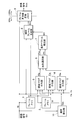
- FIG. 1 is a block diagram showing a frame frequency conversion apparatus including the motion vector detection apparatus of the first embodiment.
- FIG. 2 is a diagram showing an area flag provided to each pixel in a frame in the motion vector detection apparatus of the first embodiment.
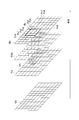
- FIG. 3 is a diagram for explaining the normal operation of the pixel selection unit when the search range is located within the effective display area.
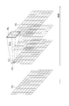
- FIG. 4 is a diagram showing an example where a part of the search range is located outside the effective display area.
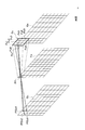
- FIG. 5 is a diagram for explaining the operation of the pixel selection unit when a part of the search range is located outside the effective display area.
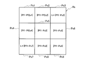
- FIG. 6A is a diagram showing a difference value calculated by the pixel selection unit in the normal operation shown in FIG. FIG.
- FIG. 6B is a diagram showing a difference value calculated by the pixel selection unit at the time of the operation shown in FIG.
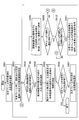
- FIG. 7A is a flowchart showing the operation of the pixel selection unit.
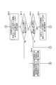
- 7B is a flowchart showing an operation of the pixel selection unit following FIG. 7A.
- FIG. 8 is a block diagram showing a frame frequency conversion device including the motion vector detection device of the second embodiment.
- FIG. 9 is a view showing an area flag provided to each pixel in a frame when the video signal includes a black band area in the motion vector detection device of the second embodiment.
- the motion vector detection device of each embodiment will be described with reference to the attached drawings.
- the configuration in which the frame frequency conversion device includes the motion vector detection device of each embodiment will be described as an example.
- the motion vector detection device may be provided other than the frame frequency conversion device.
- the video signal Sin input to the frame frequency conversion device is supplied to the frame memory 1, the area flag assignment unit 3, the interpolation frame generation unit 8, and the frame frequency conversion memory 9.
- the frame of the video signal Sin be a frame f0.
- the frame frequency of the video signal Sin is 60 Hz as an example.
- the frame memory 1 delays the video signal Sin by one frame period to generate a frame f1 of one frame past with respect to the frame f0.
- the frame f1 is supplied to the frame memory 2, the area flag assigning unit 4, and the interpolation frame generation unit 8.
- the frame memory 2 delays the frame f1 by one frame period to generate a frame f2 one frame before the frame f1.
- the frame f2 is supplied to the area flag assigning unit 5.
- the frame f1 located at the center is the frame of interest
- the frame f0 located further in the future than the frame of interest f1 is the future frame
- Frame f2 is a past frame.
- the horizontal synchronization signal Hs and the vertical synchronization signal Vs of the video signal Sin are input to the area flag adding units 3 to 5.
- the horizontal synchronization pulse and the vertical synchronization pulse generated based on the horizontal synchronization signal Hs and the vertical synchronization signal Vs may be input to the area flag adding units 3 to 5.
- the area flag assigner 3 sets each of the effective display areas f0e of the frame f0 as an area flag based on the horizontal synchronization signal Hs and the vertical synchronization signal Vs (horizontal synchronization pulse and vertical synchronization pulse).
- a first value of 1 is given to the pixels, and a second value of 0 is given to each pixel outside the effective display area f0e.
- the frames shown in FIG. 2 and the subsequent drawings are conceptual diagrams in which the number of pixels is significantly reduced for simplification.
- the area flag adding unit 3 supplies a flagged frame f0a including the area flag Ff0 added as shown in FIG. 2 and each pixel signal of the frame f0 to the pixel selecting unit 6.
- Each pixel located outside the effective display area f0e in the frame f0 has a pixel value of 0, for example.
- the area flag adding units 4 and 5 select the flagged frames f1a and f2a including the area flags added to the frames f1 and f2 and the pixel signals of the frames f1 and f2 in the same manner as the area flag adding unit 3, respectively.
- the pixel selection unit 6 sequentially takes the pixels at each pixel position in the effective display area f1 e of the target frame f1 as the target pixel, and sets a search range corresponding to the target pixel in the future frame f0.
- the search range is a range including a plurality of pixels when finding a pixel in the future frame f0 having the highest correlation with the target pixel.
- the search range is a range of a predetermined shape centering on a pixel in the future frame f0 at the same pixel position as the target pixel.
- FIG. 3 to 5 show the effective display areas f0e, f1e and f2e of the future frame f0, the target frame f1 and the past frame f2.
- the pixel selection unit 6 selects a hatched pixel in the effective display area f1e of the target frame f1 as the target pixel Pf1.
- the pixel selection unit 6 sets a search range Rs centered on the pixel at the same pixel position as the target pixel Pf1 in the effective display area f0e of the future frame f0.
- search range Rs is square, it may be rectangular long in the horizontal direction, and the shape of the search range Rs is not limited.
- the search range Rs includes the pixels Ps1 to Ps9.
- the pixel selection unit 6 calculates the difference value between the pixel of interest Pf1 and each of the pixels Ps1 to Ps9, and selects the pixel with the smallest difference value (that is, the highest correlation).
- the pixel selection unit 6 extracts a pixel selected in the search range Rs of the future frame f0 as a selected pixel Psx.
- the pixel selection unit 6 supplies the information indicating the pixel position of the target pixel Pf1 and the information indicating the pixel position of the selected pixel Psx to the motion vector detection unit 7 as correlation information.
- the motion vector detection unit 7 is sequentially supplied with the correlation information obtained in each target pixel Pf1 of the target frame f1.
- FIGS. 4 and 5 the operation of the pixel selection unit 6 when a part of the search range Rs is located outside the effective display area f0e will be described using FIGS. 4 and 5.
- the case where the pixel selection part 6 selects the hatched pixel located in the left end part of the uppermost line of the effective display area f1e as an attention pixel Pf1 is made into an example.
- a part of the search range Rs set in the future frame f0 by the pixel selection unit 6 is outside the effective display area f0e.
- the pixel selection unit 6 selects the target pixel Pf1 from a plurality of lines located at the upper and lower ends of the effective display area f1e and a plurality of pixels located at the left and right ends, as in FIG. 5, a part of the search range Rs Is outside the effective display area f0e. In order to detect the correct motion vector when frame-in or frame-out occurs, it is necessary that the motion vector be properly detected even if part of the search range Rs is outside the effective display area f0e It is.
- the pixel selection unit 6 can recognize which of the pixels Ps1 to Ps9 in the search range Rs is located outside the effective display area f0e based on the area flag Ff0.
- the pixels Ps1 to Ps4 and Ps7 are located outside the effective display area f0e.
- the pixel selection unit 6 When trying to calculate the difference value between the pixel of interest Pf1 and the pixel Ps1, the pixel selection unit 6 recognizes that the pixel Ps1 is located outside the effective display area f0e. Therefore, instead of the pixel Ps1, the pixel selection unit 6 selects the pixel Pf2s1 in the effective display area f2e of the past frame f2 which is point symmetrical with the pixel Ps1 centering on the target pixel Pf1, and selects the target pixel Pf1 and the pixel The difference value with Pf2s1 is calculated.
- the pixel selection unit 6 selects the pixels Pf2s2 and Pf2s4 in the effective display area f2e located in point symmetry with the pixels Ps2 and Ps4 centering on the pixel of interest Pf1.
- the difference value between the pixel of interest Pf1 and the pixels Pf2s2 and Pf2s4 is calculated.
- the pixel selection unit 6 When trying to calculate the difference value between the pixel of interest Pf1 and the pixel Ps3 or Ps7, the pixel selection unit 6 recognizes that the pixels Ps3 and Ps7 are located outside the effective display area f0e. However, a position symmetrical to the pixel Ps3 or Ps7 with respect to the pixel Pf1 of interest does not exist in the effective display area f2e, and pixels in the past frame f2 can not be used instead of the pixels Ps3 and Ps7.
- the pixel selection unit 6 calculates the difference value between the target pixel Pf1 and the pixel Ps3 and the difference value between the target pixel Pf1 and the pixel Ps7. As described above, since each pixel located outside the effective display area f0e has a pixel value of 0, the difference value between the focused pixel Pf1 and the pixel Ps3 and the difference value between the focused pixel Pf1 and the pixel Ps7 are very large. It can be a large value.
- the difference value between the target pixel Pf1 and the pixel Ps3 is a large value, so the pixel Ps3 is selected as the pixel with the smallest difference value.
- the direction from the target pixel Pf1 to the pixel Ps3 is highly likely to be a motion vector, it is necessary to increase the possibility that the pixel Ps3 is selected as the pixel with the smallest difference value.
- the pixel selection unit 6 refers to the correlation information generated in the neighboring pixels of the target pixel Pf1 in the target frame f1, and the difference value between the target pixel Pf1 and the pixel Ps3 and the target pixel Pf1 and the pixel Ps7. Adjust the difference value.
- the neighboring pixels are pixels located on the upper side, lower side, left side, or right side.
- the target pixel Pf1 since the target pixel Pf1 is located at the left end of the uppermost line of the effective display area f1e, there is no detection result in the selection direction before the processing for the target pixel Pf1. Even in such a case, it is possible to adjust the difference value by feeding back the correlation information obtained when, for example, the pixel positioned on the right of the pixel of interest Pf1 shown in FIG. 5 is the pixel of interest Pf1. it can.
- the pixel selection unit 6 may adjust the difference value with reference to the correlation information generated in the pixel at the same pixel position as the target pixel Pf1 in the target frame f1 in the past frame f2.
- the pixels at the same pixel position in the past frame f2 are neighboring pixels in the time direction.
- the pixel selection unit 6 may adjust the difference value with reference to the correlation information generated in the neighboring pixels not only at the same pixel position as the target pixel Pf1 in the target frame f1 in the past frame f2. .
- the pixel selection unit 6 determines the difference between the pixel of interest Pf1 and the pixel Ps3 and the difference between the pixel of interest Pf1 and the pixel Ps7 as the degree of similarity of correlation information generated in neighboring pixels in the frame of interest f1 or the past frame f2 increases. Adjust to lower the value.
- the pixel selection unit 6 calculates difference values between the pixel of interest Pf1 and the pixels Ps5, Ps6, Ps8, and Ps9.
- the pixel selection unit 6 adjusts the difference values between the pixel of interest Pf1 and the pixels Pf2s1, Pf2s2 and Pf2s4, the difference between the pixel of interest Pf1 and the pixels Ps3 and Ps7, and the pixel of interest Pf1. And respective difference values with the pixels Ps5, Ps6, Ps8, and Ps9.
- the pixel selection unit 6 selects a pixel with the smallest difference value from among these.
- FIG. 6A shows the difference value calculated by the pixel selection unit 6 by the operation described in FIG. 3
- FIG. 6B shows the difference value calculated by the pixel selection unit 6 by the operation described in FIG.
- the difference value between the pixel of interest Pf1 and each of the pixels Ps1 to Ps9 is calculated.
- the pixel selection unit 6 sets the coefficient k to an appropriate value with reference to the correlation information generated in the neighboring pixels of the target pixel Pf1.
- the pixel selection unit 6 reduces the value of the coefficient k as the similarity of the correlation information is higher.
- the motion vector detection unit 7 connects each focused pixel Pf1 in the focused frame f1 with the selected pixel Psx in the search range Rs selected corresponding to each focused pixel Pf1, based on the correlation information.
- the direction is detected as a motion vector MV.
- the motion vector detection unit 7 supplies the motion vector MV to the interpolation frame generation unit 8.
- the motion vector detection unit 7 may supply the motion vector MV detected for each pixel of interest Pf1 to the interpolation frame generation unit 8 as it is.
- the motion vector detection unit 7 may generate a motion vector MV for each block composed of a plurality of pixels based on the motion vector MV detected for each pixel of interest Pf 1 and supply the motion vector MV to the interpolation frame generation unit 8.
- parts of a frame memory 1 to a motion vector detection unit 7 constitute a motion vector detection device of the first embodiment.
- the frame memories 1 and 2 may be external to the frame frequency converter.
- the motion vector detection device according to the first embodiment includes at least region flag assigning units 3 to 5, a pixel selection unit 6, and a motion vector detection unit 7.
- the interpolation frame generation unit 8 selects and mixes the pixel in the frame of interest f1 and the pixel in the future frame f0 based on the motion vector MV to generate an interpolation pixel at each pixel position, as shown in FIG. 3 or FIG.
- the interpolation frame f 0.5 is supplied to the frame frequency conversion memory 9.
- the frame frequency conversion memory 9 writes the future frame f0 and the interpolation frame f0.5 and reads the interpolation frame f0.5 and the future frame f0 in the order of twice the frequency to generate the video signal Sout having a frame frequency of 120 Hz. Do.
- the frame frequency conversion device interpolates the interpolation frame f0.5 between the adjacent frame of interest f1 and the future frame f0 to obtain a frame that is twice the frame frequency of the input video signal Sin.
- a video signal Sout with a frequency of 120 Hz can be output.
- step S601 the pixel selection unit 6 selects the first target pixel Pf1 in the target frame f1.
- step S602 the pixel selection unit 6 sets a search range Rs corresponding to the selected target pixel Pf1 in the future frame f0.
- step S603 the pixel selection unit 6 determines whether acquisition of difference values between the pixel of interest Pf1 and all the pixels in the search range Rs has been completed. If the acquisition of the difference value is completed (YES), the pixel selection unit 6 selects the pixel in the search range Rs having the smallest difference value in step S604. In step S605, the pixel selection unit 6 supplies the motion vector detection unit 7 with information on the pixel of interest Pf1 and the selected pixel in the search range Rs.
- step S606 the pixel selection unit 6 determines whether the processing for all the pixels in the frame of interest f1 is completed. If the processing for all the pixels is completed (YES), the pixel selection unit 6 ends the processing. If the processing for all the pixels is not completed (NO), the pixel selection unit 6 selects the next target pixel Pf1 in the target frame f1 in step S607, and repeats the processing in steps S602 to S606.
- the pixel selection unit 6 determines pixels in the search range Rs in step S608. One of the pixels for which the difference value with respect to the pixel of interest Pf1 has not been acquired is selected. In step S609, the pixel selection unit 6 determines whether the area flag of the pixel selected in the future frame f0 is one.
- the pixel selection unit 6 determines in step S610 whether the area flag of the target pixel Pf1 selected in the target frame f1 is 1. If the area flag is 1 (YES), the pixel selection unit 6 acquires the difference value between the pixel of interest Pf1 in the frame of interest f1 and the pixel selected in the search range Rs of the future frame f0 in step S611. Then, the process returns to step S603.
- step S610 If the region flag of the pixel of interest Pf1 selected in the frame of interest f1 in step S610 is not 1 (NO), the pixel selection unit 6 returns the process to step S606.
- the pixel selection unit 6 selects the future frame f0 at step S612 in FIG. 7B, centering on the pixel of interest Pf1.
- the pixel in the past frame f2 which is point-symmetrical to the selected pixel is selected.
- step S613 the pixel selection unit 6 determines whether the area flag of the pixel selected in the past frame f2 is one. If the area flag is 1 (YES), the pixel selection unit 6 determines in step S614 whether the area flag of the target pixel Pf1 selected in the target frame f1 is 1.
- step S614 If the area flag is 1 in step S614 (YES), the pixel selection unit 6 acquires the difference value between the pixel of interest Pf1 in the frame of interest f1 and the pixel selected in the past frame f2 in step S615. Then, the process returns to step S603 in FIG. 7A. If the area flag is not 1 at step S614 (NO), the pixel selection unit 6 returns the process to step S606 of FIG. 7A.
- step S613 If the area flag is not 1 in step S613 (NO), the pixel selection unit 6 refers to the correlation information in the neighboring pixels for which correlation information has been created in step S616, and the pixel of interest Pf1 and the search range Rs The difference value with the inner pixel is adjusted, and the process returns to step S610 in FIG. 7A.
- the interpolation frame generation unit 8 can generate an interpolation image having no sense of incongruity in both the central portion and the peripheral portion in the interpolation frame f0.5.
- the frame frequency conversion apparatus shown in FIG. 8 includes the motion vector detection apparatus of the second embodiment.
- the same parts as in FIG. 1 are given the same reference numerals, and the description thereof will be omitted.
- the video signal Sin is also supplied to the black band detection unit 10.
- the black band detection unit 10 generates the black band detection signal Sbb by detecting the presence or absence of the black band area and the range in which the black band area is present by a known method.
- the black band detection unit 10 detects a line having a luminance level equal to or less than a predetermined threshold value and a predetermined ratio or more among all pixels in one horizontal line as upper and lower black band regions, A line having a predetermined ratio or more of all pixels in one line in the vertical direction is detected as the left and right black band areas.
- the black band detection signal Sbb is supplied to the area flag adders 3-5.
- FIG. 9 shows an example of a so-called letterbox image in which the upper and lower ends of the effective display area f0e in the frame f0 are black bands.
- the area flag adding unit 3 adds a flag 0 to each pixel of the black band area even in the effective display area f0e based on the black band detection signal Sbb.
- the area flag assigning units 4 and 5 respectively assign a flag 0 to each pixel of the black band area in the effective display areas f1 e and f2 e in the frames f1 and f2.
- the pixel selection unit 6 may set a pixel other than the black band area in the effective display area f1e as the target pixel Pf1.
- the interpolation frame generation unit 8 can generate an interpolation image having no sense of incongruity in both the central portion and the peripheral portion in the interpolation frame f0.5.
- FIGS. 1 and 8 illustrate the frame frequency conversion device that doubles the frame frequency of the video signal, it may be a frame frequency conversion device that converts the frame frequency to three times or more.
- FIGS. 1 and 8 may be configured by a circuit by hardware, or at least a portion may be configured by software (computer program).
- the use of hardware and software is optional.
- the computer program may be stored and provided in a non-transitory storage medium.
Landscapes
- Engineering & Computer Science (AREA)
- Physics & Mathematics (AREA)
- General Physics & Mathematics (AREA)
- Theoretical Computer Science (AREA)
- Multimedia (AREA)
- Mathematical Physics (AREA)
- Computer Vision & Pattern Recognition (AREA)
- Pure & Applied Mathematics (AREA)
- Mathematical Analysis (AREA)
- Mathematical Optimization (AREA)
- Computational Mathematics (AREA)
- Data Mining & Analysis (AREA)
- Signal Processing (AREA)
- Computing Systems (AREA)
- Algebra (AREA)
- Databases & Information Systems (AREA)
- Software Systems (AREA)
- General Engineering & Computer Science (AREA)
- Television Systems (AREA)
Abstract
画素選択部(6)は、探索範囲(Rs)に含まれる未来フレーム(f0)の画素が有効表示領域(f0e)外の画素を含むと判定し、注目画素(Pf1)を中心として探索範囲(Rs)内の有効表示領域(f0e)外の画素(Ps1、Ps2、Ps4)と点対称の位置に過去フレーム(f2)の有効表示領域(f2e)内の画素が存在すると判定したとき、点対称の位置にある過去フレーム(f2)の有効表示領域(f2e)内の画素(Pf2s1、Pf2s2、Pf2s4)を選択する。画素選択部(6)は、注目画素(Pf1)と選択した過去フレーム(f2)の有効表示領域(f2e)内の画素(Pf2s1、Pf2s2、Pf2s4)との差分値を算出する。
Description
本開示は、画像の動きベクトルを検出する動きベクトル検出装置に関する。
隣接する2つのフレーム間に補間フレームを内挿してフレーム周波数を変換するフレーム周波数変換装置は、画像の動きベクトルを検出する動きベクトル検出装置を備える(特許文献1参照)。動きベクトル検出装置は、例えば隣接する2つのフレーム間の画素を比較することによって画像の動きを推定し、動きベクトルを検出する。
物体がフレームの外から中へと移動するフレームイン、または、物体がフレームの中から外へと移動するフレームアウトが発生すると、動きベクトル検出装置は正しい動きベクトルを検出できないことがある。正しい動きベクトルが検出されないと、フレーム周波数変換装置は正しい補間画素を生成することができないため、違和感のある補間フレームが生成されてしまう。
実施形態は、フレームインまたはフレームアウトが発生した場合であっても正しい動きベクトルを検出することができる動きベクトル検出装置を提供することを目的とする。
実施形態の一態様によれば、映像信号における時間方向に並ぶ3つのフレームのうち、中央に位置するフレームを注目フレーム、前記注目フレームより未来に位置するフレームを未来フレーム、前記注目フレームより過去に位置するフレームを過去フレームとし、領域フラグ付与部と、画素選択部と、動きベクトル検出部とを備える動きベクトル検出装置が提供される。
前記領域フラグ付与部は、前記注目フレーム、前記未来フレーム、前記過去のフレームそれぞれの有効表示領域内の各画素に領域フラグとして第1の値を付与し、有効表示領域外の各画素に前記領域フラグとして第2の値を付与する。
前記画素選択部は、前記注目フレームに付与された前記領域フラグに基づいて前記注目フレームの有効表示領域内の画素を注目画素として選択し、前記未来フレーム内に前記注目画素に対応する探索範囲を設定し、前記未来フレームに付与された前記領域フラグに基づいて前記探索範囲に含まれる前記未来フレームの画素が全て有効表示領域内の画素であると判定したとき、前記注目画素と前記探索範囲内の全ての画素との差分値を算出し、最も差分値の小さい画素を選択して選択画素として抽出し、前記注目画素の画素位置を示す情報と前記選択画素の画素位置を示す情報とを含む相関情報を生成する。
前記動きベクトル検出部は、前記相関情報に基づいて、前記注目画素における動きベクトルを検出する。
前記画素選択部は、前記未来フレームに付与された前記領域フラグに基づいて前記探索範囲に含まれる前記未来フレームの画素が有効表示領域外の画素を含むと判定し、前記過去フレームに付与された前記領域フラグに基づいて前記注目画素を中心として前記探索範囲内の有効表示領域外の画素と点対称の位置に前記過去フレームの有効表示領域内の画素が存在すると判定したとき、前記探索範囲内の有効表示領域外の画素の代わりに前記点対称の位置にある前記過去フレームの有効表示領域内の画素を選択し、前記注目画素と選択した前記過去フレームの有効表示領域内の画素との差分値を算出する。
実施形態の動きベクトル検出装置によれば、フレームインまたはフレームアウトが発生した場合であっても正しい動きベクトルを検出することができる。
以下、各実施形態の動きベクトル検出装置について、添付図面を参照して説明する。フレーム周波数変換装置が各実施形態の動きベクトル検出装置を備える構成を例として説明する。動きベクトル検出装置は、フレーム周波数変換装置以外に備えられていてもよい。
<第1実施形態>
図1において、フレーム周波数変換装置に入力された映像信号Sinは、フレームメモリ1、領域フラグ付与部3、補間フレーム生成部8、フレーム周波数変換メモリ9に供給される。映像信号Sinのフレームをフレームf0とする。映像信号Sinのフレーム周波数は一例として60Hzである。
図1において、フレーム周波数変換装置に入力された映像信号Sinは、フレームメモリ1、領域フラグ付与部3、補間フレーム生成部8、フレーム周波数変換メモリ9に供給される。映像信号Sinのフレームをフレームf0とする。映像信号Sinのフレーム周波数は一例として60Hzである。
フレームメモリ1は、映像信号Sinを1フレーム期間遅延して、フレームf0に対して1フレーム過去のフレームf1を生成する。フレームf1は、フレームメモリ2、領域フラグ付与部4、補間フレーム生成部8に供給される。フレームメモリ2は、フレームf1を1フレーム期間遅延して、フレームf1に対して1フレーム過去のフレームf2を生成する。フレームf2は、領域フラグ付与部5に供給される。
映像信号Sinにおける時間方向に並ぶ3つのフレームf0、f1、f2のうち、中央に位置するフレームf1を注目フレーム、注目フレームf1より未来に位置するフレームf0を未来フレーム、注目フレームf1より過去に位置するフレームf2を過去フレームとする。
領域フラグ付与部3~5には、映像信号Sinの水平同期信号Hs及び垂直同期信号Vsが入力される。水平同期信号Hs及び垂直同期信号Vsの代わりに、水平同期信号Hs及び垂直同期信号Vsに基づいて生成した水平同期パルス及び垂直同期パルスが領域フラグ付与部3~5に入力されてもよい。
図2に示すように、領域フラグ付与部3は、水平同期信号Hs及び垂直同期信号Vs(水平同期パルス及び垂直同期パルス)に基づいて、領域フラグとして、フレームf0の有効表示領域f0e内の各画素に第1の値である1を付与し、有効表示領域f0e外の各画素に第2の値である0を付与する。図2及びそれ以降の図に示されるフレームは、簡略化のため、画素数を大幅に少なくした概念図である。
領域フラグ付与部3は、図2に示すように付与した領域フラグFf0とフレームf0の各画素信号とを含むフラグ付きフレームf0aを画素選択部6に供給する。フレームf0内の有効表示領域f0eの外側に位置する各画素は、例えば画素値0とされている。
領域フラグ付与部4及び5は、領域フラグ付与部3と同様に、それぞれ、フレームf1及びf2に付与した領域フラグとフレームf1及びf2の各画素信号とを含むフラグ付きフレームf1a及びf2aを画素選択部6に供給する。フレームf0内の有効表示領域f0eの外側に位置する各画素が画素値0であるから、フレームf1及びf2内の有効表示領域f1e及びf2e(図3参照)の外側に位置する各画素は画素値0である。
画素選択部6は、注目フレームf1の有効表示領域f1e内の各画素位置の画素を順に注目画素とし、未来フレームf0内に注目画素に対応する探索範囲を設定する。探索範囲とは、注目画素と最も相関の高い未来フレームf0内の画素を求める際の複数の画素よりなる範囲である。典型的には、探索範囲は、注目画素と同じ画素位置の未来フレームf0内の画素を中心とする所定形状の範囲である。
まず、図3を用いて、探索範囲が有効表示領域f0e内に位置するときの画素選択部6の通常の動作を説明する。図3~図5においては、未来フレームf0、注目フレームf1、過去フレームf2のうちの有効表示領域f0e、f1e、f2eを示している。図3に示すように、画素選択部6が注目フレームf1の有効表示領域f1e内のハッチングを付した画素を注目画素Pf1として選択したとする。このとき、画素選択部6は、未来フレームf0の有効表示領域f0e内に、注目画素Pf1と同じ画素位置の画素を中心とする探索範囲Rsを設定する。
ここでは探索範囲Rsを正方形状としているが、水平方向に長い長方形状であってもよく、探索範囲Rsの形状は限定されない。ここでは、探索範囲Rsは画素Ps1~Ps9を含む。
図1において、画素選択部6は、注目画素Pf1と画素Ps1~Ps9それぞれとの差分値を算出し、最も差分値の小さい(即ち、最も相関の高い)画素を選択する。画素選択部6は、未来フレームf0の探索範囲Rs内で選択した画素を選択画素Psxとして抽出する。画素選択部6は、注目画素Pf1の画素位置を示す情報と選択画素Psxの画素位置を示す情報とを相関情報として動きベクトル検出部7に供給する。
動きベクトル検出部7には、注目フレームf1の各注目画素Pf1において得られた相関情報が順に供給される。
次に、図4及び図5を用いて、探索範囲Rsの一部が有効表示領域f0e外に位置するときの画素選択部6の動作を説明する。図4に示すように、画素選択部6が有効表示領域f1eの最上位ラインの左端部に位置するハッチングを付した画素を注目画素Pf1として選択した場合を例とする。このとき、画素選択部6が未来フレームf0内に設定する探索範囲Rsは、一部が有効表示領域f0eの外側となる。
画素選択部6が、有効表示領域f1eの上下端部に位置する複数ライン、左右端部に位置する複数の画素から注目画素Pf1を選択したときには、図5と同様に、探索範囲Rsの一部が有効表示領域f0eの外側となる。フレームインまたはフレームアウトが発生した場合に正しい動きベクトルを検出するには、探索範囲Rsの一部が有効表示領域f0eの外側となる場合であっても動きベクトルが適切に検出されることが必要である。
画素選択部6は、領域フラグFf0に基づいて、探索範囲Rsの画素Ps1~Ps9のうち、どの画素が有効表示領域f0eの外側に位置するかを認識することができる。ここでは、図5に示すように、画素Ps1~Ps4及びPs7が有効表示領域f0eの外側に位置する。
画素選択部6は、注目画素Pf1と画素Ps1との差分値を算出しようとするとき、画素Ps1が有効表示領域f0eの外側に位置することを認識する。そこで、画素選択部6は、画素Ps1の代わりに、注目画素Pf1を中心して画素Ps1と点対称の位置にある過去フレームf2の有効表示領域f2e内の画素Pf2s1を選択し、注目画素Pf1と画素Pf2s1との差分値を算出する。
同様にして、画素選択部6は、画素Ps2及びPs4の代わりに、注目画素Pf1を中心して画素Ps2及びPs4それぞれと点対称の位置にある有効表示領域f2e内の画素Pf2s2及びPf2s4を選択し、注目画素Pf1と画素Pf2s2及びPf2s4との差分値を算出する。
画素選択部6は、注目画素Pf1と画素Ps3またはPs7との差分値を算出しようとするとき、画素Ps3及びPs7が有効表示領域f0eの外側に位置することを認識する。しかしながら、注目画素Pf1を中心して画素Ps3またはPs7と点対称の位置は有効表示領域f2e内に存在せず、画素Ps3及びPs7の代わりに過去フレームf2内の画素を用いることはできない。
そこで、画素選択部6は、注目画素Pf1と画素Ps3との差分値、注目画素Pf1と画素Ps7との差分値を算出する。上記のように、有効表示領域f0eの外側に位置する各画素は画素値0とされているから、注目画素Pf1と画素Ps3との差分値、注目画素Pf1と画素Ps7との差分値は非常に大きな値となることがある。
仮に、注目画素Pf1から画素Ps3へと向かう方向が動きベクトルであったとしても、注目画素Pf1と画素Ps3との差分値が大きな値であるため、画素Ps3が最も差分値の小さい画素として選択される可能性はほとんどない。注目画素Pf1から画素Ps3へと向かう方向が動きベクトルである可能性が高い場合には、画素Ps3が最も差分値の小さい画素として選択される可能性を増大させる必要がある。
そこで、画素選択部6は、注目フレームf1内の注目画素Pf1の近傍画素において生成された相関情報を参照して、注目画素Pf1と画素Ps3との差分値と、注目画素Pf1と画素Ps7との差分値を調整する。近傍画素とは、上、下、左、右のいずれかの隣側に位置する画素である。
図5に示す例では、注目画素Pf1が有効表示領域f1eの最上位ラインの左端部に位置するので、注目画素Pf1に対する処理を実行する以前の選択方向の検出結果が存在しない。このような場合であっても、図5に示す注目画素Pf1の例えば右隣に位置する画素を注目画素Pf1としたときに得られた相関情報をフィードバックすることによって、差分値を調整することができる。
画素選択部6は、過去フレームf2内の、注目フレームf1における注目画素Pf1と同じ画素位置の画素で生成された相関情報を参照して、差分値を調整してもよい。過去フレームf2内の同じ画素位置の画素は時間方向の近傍画素である。画素選択部6は、過去フレームf2内の、注目フレームf1における注目画素Pf1と同じ画素位置だけではなく、さらにその近傍画素において生成された相関情報を参照して、差分値を調整してもよい。
画素選択部6は、注目フレームf1または過去フレームf2内の近傍画素で生成された相関情報の類似度が高いほど、注目画素Pf1と画素Ps3との差分値、注目画素Pf1と画素Ps7との差分値を小さくするように調整する。
画素Ps5、Ps6、Ps8、Ps9は有効表示領域f0e内に存在するので、画素選択部6は、注目画素Pf1と画素Ps5、Ps6、Ps8、Ps9それぞれとの差分値を算出する。
以上のようにして、画素選択部6は、注目画素Pf1と画素Pf2s1、Pf2s2、Pf2s4との各差分値、注目画素Pf1と画素Ps3及びPs7との差分値を調整した調整差分値、注目画素Pf1と画素Ps5、Ps6、Ps8、Ps9との各差分値とを取得する。画素選択部6は、これらの中から、最も差分値の小さい画素を選択する。
図6Aは図3で説明した動作によって画素選択部6が算出する差分値を示し、図6Bは図5で説明した動作によって画素選択部6が算出する差分値を示している。図6Aに示すように、探索範囲Rsの全てが有効表示領域f0e内に位置する場合には、注目画素Pf1と画素Ps1~Ps9それぞれとの差分値が算出される。
図6Bに示すように、探索範囲Rsの一部が有効表示領域f0e外に位置する場合で、有効表示領域f0e外に位置する画素位置において点対称の画素が過去フレームf2の有効表示領域f2e内に存在する場合には、注目画素Pf1と有効表示領域f2e内の画素との差分値が算出される。有効表示領域f0e外に位置する画素位置において点対称の画素が有効表示領域f2e内に存在しない場合には、注目画素Pf1と探索範囲Rs内の画素との差分値に所定の係数kを乗じた調整差分値が算出される。係数kは1以下の数である。
画素選択部6は、注目画素Pf1の近傍画素で生成された相関情報を参照して係数kを適宜の値に設定する。画素選択部6は、相関情報の類似度が高いほど係数kの値を小さくする。
図1に戻り、動きベクトル検出部7は、相関情報に基づいて、注目フレームf1内の各注目画素Pf1と、各注目画素Pf1に対応して選択した探索範囲Rs内の選択画素Psxとを結ぶ方向を動きベクトルMVとして検出する。動きベクトル検出部7は、動きベクトルMVを補間フレーム生成部8に供給する。
動きベクトル検出部7は、注目画素Pf1ごとに検出した動きベクトルMVをそのまま補間フレーム生成部8に供給してもよい。動きベクトル検出部7は、注目画素Pf1ごとに検出した動きベクトルMVに基づいて、複数の画素よりなるブロックごとの動きベクトルMVを生成して、補間フレーム生成部8に供給してもよい。
後者の場合、例えば、画素単位の動きベクトルMVをブロック内で平均することにより、一部の注目画素Pf1において動きベクトルMVの誤検出が発生したとしても、ブロック全体ではほぼ正しい動きベクトルMVとすることができる。
図1において、フレームメモリ1~動きベクトル検出部7の部分は、第1実施形態の動きベクトル検出装置を構成する。フレームメモリ1及び2はフレーム周波数変換装置の外部にあってもよい。第1実施形態の動きベクトル検出装置は、少なくとも領域フラグ付与部3~5、画素選択部6、動きベクトル検出部7を備える。
補間フレーム生成部8は、動きベクトルMVに基づいて、注目フレームf1内の画素と未来フレームf0内の画素とを選択して混合して各画素位置の補間画素を生成し、図3または図4に示す補間フレームf0.5を生成する。補間フレームf0.5はフレーム周波数変換メモリ9に供給される。
フレーム周波数変換メモリ9は、未来フレームf0と補間フレームf0.5とを書き込み、補間フレームf0.5、未来フレームf0の順に2倍の周波数で読み出すことにより、フレーム周波数120Hzを有する映像信号Soutを生成する。
以上のようにして、フレーム周波数変換装置は、隣接する注目フレームf1と未来フレームf0との間に補間フレームf0.5を内挿して、入力された映像信号Sinのフレーム周波数の2倍であるフレーム周波数120Hzの映像信号Soutを出力することができる。
図7A及び図7Bに示すフローチャートを用いて、画素選択部6の1フレーム内での動作を改めて説明する。図7Aにおいて、画素選択部6は、ステップS601にて、注目フレームf1内の最初の注目画素Pf1を選択する。画素選択部6は、ステップS602にて、未来フレームf0内に、選択された注目画素Pf1に対応する探索範囲Rsを設定する。
画素選択部6は、ステップS603にて、注目画素Pf1と探索範囲Rs内の全画素との差分値の取得が完了したか否かを判定する。差分値の取得が完了していれば(YES)、画素選択部6は、ステップS604にて、探索範囲Rs内の最も差分値が小さい画素を選択する。画素選択部6は、ステップS605にて、動きベクトル検出部7に、注目画素Pf1及び探索範囲Rs内の選択された画素の情報を供給する。
画素選択部6は、ステップS606にて、注目フレームf1内の全画素に対する処理が完了したか否かを判定する。全画素に対する処理が完了していれば(YES)、画素選択部6は処理を終了する。全画素に対する処理が完了していなければ(NO)、画素選択部6は、ステップS607にて、注目フレームf1内の次の注目画素Pf1を選択して、ステップS602~S606の処理を繰り返す。
一方、ステップS603にて注目画素Pf1と探索範囲Rs内の全画素との差分値の取得が完了していなければ(NO)、画素選択部6は、ステップS608にて、探索範囲Rs内の画素のうち注目画素Pf1との差分値を取得していない画素を1つ選択する。画素選択部6は、ステップS609にて、未来フレームf0内で選択した画素の領域フラグが1であるか否かを判定する。
領域フラグが1であれば(YES)、画素選択部6は、ステップS610にて、注目フレームf1内で選択した注目画素Pf1の領域フラグが1であるか否かを判定する。領域フラグが1であれば(YES)、画素選択部6は、ステップS611にて、注目フレームf1内の注目画素Pf1と未来フレームf0の探索範囲Rs内で選択した画素との差分値を取得して、処理をステップS603に戻す。
ステップS610にて注目フレームf1内で選択した注目画素Pf1の領域フラグが1でなければ(NO)、画素選択部6は、処理をステップS606に戻す。
ステップS609にて未来フレームf0内で選択した画素の領域フラグが1でなければ(NO)、画素選択部6は、図7BのステップS612にて、注目画素Pf1を中心として、未来フレームf0で選択した画素と点対称となる過去フレームf2内の画素を選択する。
画素選択部6は、ステップS613にて、過去フレームf2内で選択した画素の領域フラグが1であるか否かを判定する。領域フラグが1であれば(YES)、画素選択部6は、ステップS614にて、注目フレームf1内で選択した注目画素Pf1の領域フラグが1であるか否かを判定する。
ステップS614にて領域フラグが1であれば(YES)、画素選択部6は、ステップS615にて、注目フレームf1内の注目画素Pf1と過去フレームf2内で選択した画素との差分値を取得して、処理を図7AのステップS603に戻す。ステップS614にて領域フラグが1でなければ(NO)、画素選択部6は、処理を図7AのステップS606に戻す。
ステップS613にて領域フラグが1でなければ(NO)、画素選択部6は、ステップS616にて、相関情報を作成済みの近傍画素での相関情報を参照して、注目画素Pf1と探索範囲Rs内の画素との差分値を調整して、処理を図7AのステップS610に戻す。
以上のようにして、第1実施形態の動きベクトル検出装置によれば、探索範囲Rsの一部が有効表示領域f0e外に位置したとしても正しい動きベクトルが検出され、フレームインまたはフレームアウトが発生した場合であっても正しい動きベクトルを検出することができる。第1実施形態の動きベクトル検出装置を用いれば、補間フレーム生成部8は、補間フレームf0.5内の中央部及び周辺部の双方で違和感のない補間画像を生成することができる。
<第2実施形態>
図8に示すフレーム周波数変換装置は、第2実施形態の動きベクトル検出装置を備える。図8において、図1と同一部分には同一符号を付し、その説明を省略する。
図8に示すフレーム周波数変換装置は、第2実施形態の動きベクトル検出装置を備える。図8において、図1と同一部分には同一符号を付し、その説明を省略する。
図8において、映像信号Sinは、黒帯検出部10にも供給される。黒帯検出部10は、公知の手法によって黒帯領域の有無、及び、黒帯領域が存在する範囲を検出して、黒帯検出信号Sbbを生成する。一例として、黒帯検出部10は、輝度レベルが所定の閾値以下であって、水平方向の1ラインの全画素のうちの所定の割合以上のラインを上下の黒帯領域であると検出し、垂直方向の1ラインの全画素のうちの所定の割合以上のラインを左右の黒帯領域であると検出する。黒帯検出信号Sbbは、領域フラグ付与部3~5に供給される。
図9は、フレームf0内の有効表示領域f0eの上下端部が黒帯領域となっている、いわゆるレターボックスの画像を例として示している。領域フラグ付与部3は、黒帯検出信号Sbbに基づいて、有効表示領域f0e内であっても、黒帯領域の各画素にフラグ0を付与する。領域フラグ付与部4及び5も同様に、それぞれ、フレームf1及びf2内の有効表示領域f1e及びf2e内の黒帯領域の各画素にフラグ0を付与する。
画素選択部6以降の動作は、第1実施形態の動きベクトル検出装置と同じである。第2実施形態の動きベクトル検出装置においては、画素選択部6は、有効表示領域f1e内の黒帯領域以外の画素を注目画素Pf1とすればよい。
第2実施形態の動きベクトル検出装置によれば、探索範囲Rsの一部が黒帯領域内であっても、第1実施形態の動きベクトル検出装置と同様の処理によって正しい動きベクトルが検出され、フレームインまたはフレームアウトが発生した場合であっても正しい動きベクトルを検出することができる。第2実施形態の動きベクトル検出装置を用いれば、補間フレーム生成部8は、補間フレームf0.5内の中央部及び周辺部の双方で違和感のない補間画像を生成することができる。
図1及び図8では、映像信号のフレーム周波数を2倍に変換するフレーム周波数変換装置を例としたが、フレーム周波数を3倍以上に変換するフレーム周波数変換装置としてもよい。
図1及び図8の各部をハードウェアによる回路によって構成してもよいし、少なくとも一部をソフトウェア(コンピュータプログラム)によって構成してもよい。ハードウェアとソフトウェアとの使い分けは任意である。コンピュータプログラムは非一時的な記憶媒体に記憶されて提供されてもよい。
本願の開示は、2017年9月27日に出願された特願2017-185638号に記載の主題と関連しており、それらの全ての開示内容は引用によりここに援用される。
既に述べられたもの以外に、本発明の新規かつ有利な特徴から外れることなく、上記の実施形態に様々な修正や変更を加えてもよいことに注意すべきである。従って、そのような全ての修正や変更は、添付の請求の範囲に含まれることが意図されている。
既に述べられたもの以外に、本発明の新規かつ有利な特徴から外れることなく、上記の実施形態に様々な修正や変更を加えてもよいことに注意すべきである。従って、そのような全ての修正や変更は、添付の請求の範囲に含まれることが意図されている。
Claims (3)
- 映像信号における時間方向に並ぶ3つのフレームのうち、中央に位置するフレームを注目フレーム、前記注目フレームより未来に位置するフレームを未来フレーム、前記注目フレームより過去に位置するフレームを過去フレームとし、
前記注目フレーム、前記未来フレーム、前記過去のフレームそれぞれの有効表示領域内の各画素に領域フラグとして第1の値を付与し、有効表示領域外の各画素に前記領域フラグとして第2の値を付与する領域フラグ付与部と、
前記注目フレームに付与された前記領域フラグに基づいて前記注目フレームの有効表示領域内の画素を注目画素として選択し、
前記未来フレーム内に前記注目画素に対応する探索範囲を設定し、
前記未来フレームに付与された前記領域フラグに基づいて前記探索範囲に含まれる前記未来フレームの画素が全て有効表示領域内の画素であると判定したとき、前記注目画素と前記探索範囲内の全ての画素との差分値を算出し、
最も差分値の小さい画素を選択して選択画素として抽出し、
前記注目画素の画素位置を示す情報と前記選択画素の画素位置を示す情報とを含む相関情報を生成する
画素選択部と、
前記相関情報に基づいて、前記注目画素における動きベクトルを検出する動きベクトル検出部と、
を備え、
前記画素選択部は、
前記未来フレームに付与された前記領域フラグに基づいて前記探索範囲に含まれる前記未来フレームの画素が有効表示領域外の画素を含むと判定し、前記過去フレームに付与された前記領域フラグに基づいて前記注目画素を中心として前記探索範囲内の有効表示領域外の画素と点対称の位置に前記過去フレームの有効表示領域内の画素が存在すると判定したとき、前記探索範囲内の有効表示領域外の画素の代わりに前記点対称の位置にある前記過去フレームの有効表示領域内の画素を選択し、
前記注目画素と選択した前記過去フレームの有効表示領域内の画素との差分値を算出する
動きベクトル検出装置。 - 前記画素選択部は、前記未来フレームに付与された前記領域フラグに基づいて前記探索範囲に含まれる前記未来フレームの画素が有効表示領域外の画素を含むと判定し、前記過去フレームに付与された前記領域フラグに基づいて前記注目画素を中心として前記探索範囲内の有効表示領域外の画素と点対称の位置に前記過去フレームの有効表示領域内の画素が存在しないと判定したとき、前記注目画素と前記探索範囲内の有効表示領域外の画素との差分値を、前記注目フレームまたは前記過去フレーム内に位置する前記注目画素の近傍画素において生成された相関情報を参照して調整する請求項1に記載の動きベクトル検出装置。
- 前記映像信号が黒帯領域を有するか否か、及び、黒帯領域を有するとき黒帯領域が存在する範囲を検出する黒帯検出部をさらに備え、
前記領域フラグ付与部は、前記黒帯検出部が前記映像信号は黒帯領域を有することを検出したとき、前記注目フレーム、前記未来フレーム、前記過去のフレームそれぞれの有効表示領域内であって前記黒帯領域内の各画素に前記第2の値を付与する
請求項1または2に記載の動きベクトル検出装置。
Priority Applications (1)
| Application Number | Priority Date | Filing Date | Title |
|---|---|---|---|
| US16/811,141 US11308631B2 (en) | 2017-09-27 | 2020-03-06 | Motion vector detection device |
Applications Claiming Priority (2)
| Application Number | Priority Date | Filing Date | Title |
|---|---|---|---|
| JP2017185638A JP6904200B2 (ja) | 2017-09-27 | 2017-09-27 | 動きベクトル検出装置 |
| JP2017-185638 | 2017-09-27 |
Related Child Applications (1)
| Application Number | Title | Priority Date | Filing Date |
|---|---|---|---|
| US16/811,141 Continuation US11308631B2 (en) | 2017-09-27 | 2020-03-06 | Motion vector detection device |
Publications (1)
| Publication Number | Publication Date |
|---|---|
| WO2019064640A1 true WO2019064640A1 (ja) | 2019-04-04 |
Family
ID=65901717
Family Applications (1)
| Application Number | Title | Priority Date | Filing Date |
|---|---|---|---|
| PCT/JP2018/010683 Ceased WO2019064640A1 (ja) | 2017-09-27 | 2018-03-19 | 動きベクトル検出装置 |
Country Status (3)
| Country | Link |
|---|---|
| US (1) | US11308631B2 (ja) |
| JP (1) | JP6904200B2 (ja) |
| WO (1) | WO2019064640A1 (ja) |
Cited By (1)
| Publication number | Priority date | Publication date | Assignee | Title |
|---|---|---|---|---|
| WO2020221258A1 (en) * | 2019-04-28 | 2020-11-05 | Beijing Bytedance Network Technology Co., Ltd. | Symmetric motion vector difference coding |
Families Citing this family (1)
| Publication number | Priority date | Publication date | Assignee | Title |
|---|---|---|---|---|
| US20240112356A1 (en) * | 2022-09-30 | 2024-04-04 | Nvidia Corporation | Estimating flow vectors for occluded content in video sequences |
Citations (5)
| Publication number | Priority date | Publication date | Assignee | Title |
|---|---|---|---|---|
| JPH0779474B2 (ja) * | 1991-04-19 | 1995-08-23 | 株式会社グラフィックス・コミュニケーション・テクノロジーズ | 動ベクトル演算装置 |
| JP2001298637A (ja) * | 2000-02-10 | 2001-10-26 | Sony Corp | 画像処理装置および方法、並びに記録媒体 |
| JP2008271493A (ja) * | 2007-03-27 | 2008-11-06 | Mega Chips Corp | 動き探索方法 |
| JP2010010818A (ja) * | 2008-06-24 | 2010-01-14 | Sharp Corp | 動きベクトル割付装置、フレームレート変換装置、動画像符号化装置、動きベクトル割付方法、動きベクトル割付プログラム、および、記録媒体 |
| WO2010100672A1 (ja) * | 2009-03-04 | 2010-09-10 | ルネサスエレクトロニクス株式会社 | 圧縮動画符号化装置、圧縮動画復号化装置、圧縮動画符号化方法および圧縮動画復号化方法 |
Family Cites Families (6)
| Publication number | Priority date | Publication date | Assignee | Title |
|---|---|---|---|---|
| JP2004007379A (ja) * | 2002-04-10 | 2004-01-08 | Toshiba Corp | 動画像符号化方法及び動画像復号化方法 |
| US8126277B2 (en) * | 2007-02-28 | 2012-02-28 | Sanyo Electric Co., Ltd. | Image processing method, image processing apparatus and image pickup apparatus using the same |
| JP2008245135A (ja) | 2007-03-28 | 2008-10-09 | Toshiba Corp | 補間フレーム作成方法および補間フレーム作成装置 |
| TWI463878B (zh) * | 2009-02-19 | 2014-12-01 | Sony Corp | Image processing apparatus and method |
| US9788010B2 (en) * | 2009-05-07 | 2017-10-10 | Texas Instruments Incorporated | Reducing computational complexity when video encoding uses bi-predictively encoded frames |
| FI20165547A1 (fi) * | 2016-06-30 | 2018-12-31 | Nokia Technologies Oy | Laitteisto, menetelmä ja tietokoneohjelma videokoodausta ja videokoodauksen purkua varten |
-
2017
- 2017-09-27 JP JP2017185638A patent/JP6904200B2/ja active Active
-
2018
- 2018-03-19 WO PCT/JP2018/010683 patent/WO2019064640A1/ja not_active Ceased
-
2020
- 2020-03-06 US US16/811,141 patent/US11308631B2/en active Active
Patent Citations (5)
| Publication number | Priority date | Publication date | Assignee | Title |
|---|---|---|---|---|
| JPH0779474B2 (ja) * | 1991-04-19 | 1995-08-23 | 株式会社グラフィックス・コミュニケーション・テクノロジーズ | 動ベクトル演算装置 |
| JP2001298637A (ja) * | 2000-02-10 | 2001-10-26 | Sony Corp | 画像処理装置および方法、並びに記録媒体 |
| JP2008271493A (ja) * | 2007-03-27 | 2008-11-06 | Mega Chips Corp | 動き探索方法 |
| JP2010010818A (ja) * | 2008-06-24 | 2010-01-14 | Sharp Corp | 動きベクトル割付装置、フレームレート変換装置、動画像符号化装置、動きベクトル割付方法、動きベクトル割付プログラム、および、記録媒体 |
| WO2010100672A1 (ja) * | 2009-03-04 | 2010-09-10 | ルネサスエレクトロニクス株式会社 | 圧縮動画符号化装置、圧縮動画復号化装置、圧縮動画符号化方法および圧縮動画復号化方法 |
Cited By (4)
| Publication number | Priority date | Publication date | Assignee | Title |
|---|---|---|---|---|
| WO2020221258A1 (en) * | 2019-04-28 | 2020-11-05 | Beijing Bytedance Network Technology Co., Ltd. | Symmetric motion vector difference coding |
| US11463703B2 (en) | 2019-04-28 | 2022-10-04 | Beijing Bytedance Network Technology Co., Ltd. | Symmetric motion vector difference coding |
| US11792406B2 (en) | 2019-04-28 | 2023-10-17 | Beijing Bytedance Network Technology Co., Ltd | Symmetric motion vector difference coding |
| US12244817B2 (en) | 2019-04-28 | 2025-03-04 | Beijing Bytedance Network Technology Co., Ltd. | Symmetric motion vector difference coding |
Also Published As
| Publication number | Publication date |
|---|---|
| JP6904200B2 (ja) | 2021-07-14 |
| JP2019062406A (ja) | 2019-04-18 |
| US11308631B2 (en) | 2022-04-19 |
| US20200211204A1 (en) | 2020-07-02 |
Similar Documents
| Publication | Publication Date | Title |
|---|---|---|
| US10666924B2 (en) | Virtual viewpoint image generation system based on captured images, virtual viewpoint image generation apparatus, and method of controlling same | |
| JP6326180B1 (ja) | 画像処理装置 | |
| US10469736B2 (en) | Control method and electronic apparatus | |
| US9591258B2 (en) | Image processing apparatus, image processing method, program and storage medium | |
| US11790583B2 (en) | Image processing apparatus, image processing method, and non-transitory computer-readable storage medium | |
| KR101783229B1 (ko) | 화상처리장치 및 그 제어 방법 | |
| US20160132282A1 (en) | Display apparatus and display methods thereof | |
| US10348966B2 (en) | Optical apparatus and a control method for performing image readout and reconstruction based on a delayed readout from different partial regions | |
| US10116865B2 (en) | Image processing apparatus and image processing method for calculating motion vector between images with different in-focus positions | |
| WO2019064640A1 (ja) | 動きベクトル検出装置 | |
| US9883096B2 (en) | Focus detection apparatus and control method thereof | |
| US9106926B1 (en) | Using double confirmation of motion vectors to determine occluded regions in images | |
| US20170078600A1 (en) | Image capturing apparatus and control method for the same | |
| US9454801B2 (en) | Image processing apparatus, method for processing image, and program | |
| JP6175878B2 (ja) | 画像処理回路、画像処理装置及び画像処理方法 | |
| US20190191057A1 (en) | Image processing device, image processing method, and program | |
| US9741086B2 (en) | Image processing apparatus, image processing method, and storage medium storing program | |
| JP6378496B2 (ja) | 画像処理装置、制御方法及び記録媒体 | |
| JP2016092806A (ja) | 画像処理装置及び画像処理方法 | |
| JP6637242B2 (ja) | 画像処理装置、撮像装置、プログラム、および画像処理方法 | |
| US11488291B2 (en) | Image processing apparatus for generating a combined image from plural captured images having been subjected to position alignment, and image processing method | |
| JP2016001852A (ja) | 撮像装置及び故障検出方法、プログラム、並びに記憶媒体 | |
| JP2011170488A (ja) | 画像処理装置、画像処理方法、画像処理プログラム、及び、電子機器 | |
| JP2007288681A (ja) | 画像処理装置および画像処理方法、並びにプログラム | |
| JP2013175992A (ja) | 撮像装置および画像処理装置 |
Legal Events
| Date | Code | Title | Description |
|---|---|---|---|
| 121 | Ep: the epo has been informed by wipo that ep was designated in this application |
Ref document number: 18861710 Country of ref document: EP Kind code of ref document: A1 |
|
| NENP | Non-entry into the national phase |
Ref country code: DE |
|
| 122 | Ep: pct application non-entry in european phase |
Ref document number: 18861710 Country of ref document: EP Kind code of ref document: A1 |