WO2019064638A1 - 虚像表示装置 - Google Patents
虚像表示装置 Download PDFInfo
- Publication number
- WO2019064638A1 WO2019064638A1 PCT/JP2018/010176 JP2018010176W WO2019064638A1 WO 2019064638 A1 WO2019064638 A1 WO 2019064638A1 JP 2018010176 W JP2018010176 W JP 2018010176W WO 2019064638 A1 WO2019064638 A1 WO 2019064638A1
- Authority
- WO
- WIPO (PCT)
- Prior art keywords
- display
- image
- visual acuity
- virtual image
- unit
- Prior art date
- Legal status (The legal status is an assumption and is not a legal conclusion. Google has not performed a legal analysis and makes no representation as to the accuracy of the status listed.)
- Ceased
Links
Images







Classifications
-
- G—PHYSICS
- G06—COMPUTING OR CALCULATING; COUNTING
- G06T—IMAGE DATA PROCESSING OR GENERATION, IN GENERAL
- G06T19/00—Manipulating three-dimensional [3D] models or images for computer graphics
- G06T19/006—Mixed reality
-
- B—PERFORMING OPERATIONS; TRANSPORTING
- B60—VEHICLES IN GENERAL
- B60K—ARRANGEMENT OR MOUNTING OF PROPULSION UNITS OR OF TRANSMISSIONS IN VEHICLES; ARRANGEMENT OR MOUNTING OF PLURAL DIVERSE PRIME-MOVERS IN VEHICLES; AUXILIARY DRIVES FOR VEHICLES; INSTRUMENTATION OR DASHBOARDS FOR VEHICLES; ARRANGEMENTS IN CONNECTION WITH COOLING, AIR INTAKE, GAS EXHAUST OR FUEL SUPPLY OF PROPULSION UNITS IN VEHICLES
- B60K35/00—Instruments specially adapted for vehicles; Arrangement of instruments in or on vehicles
- B60K35/10—Input arrangements, i.e. from user to vehicle, associated with vehicle functions or specially adapted therefor
-
- B—PERFORMING OPERATIONS; TRANSPORTING
- B60—VEHICLES IN GENERAL
- B60K—ARRANGEMENT OR MOUNTING OF PROPULSION UNITS OR OF TRANSMISSIONS IN VEHICLES; ARRANGEMENT OR MOUNTING OF PLURAL DIVERSE PRIME-MOVERS IN VEHICLES; AUXILIARY DRIVES FOR VEHICLES; INSTRUMENTATION OR DASHBOARDS FOR VEHICLES; ARRANGEMENTS IN CONNECTION WITH COOLING, AIR INTAKE, GAS EXHAUST OR FUEL SUPPLY OF PROPULSION UNITS IN VEHICLES
- B60K35/00—Instruments specially adapted for vehicles; Arrangement of instruments in or on vehicles
- B60K35/20—Output arrangements, i.e. from vehicle to user, associated with vehicle functions or specially adapted therefor
- B60K35/21—Output arrangements, i.e. from vehicle to user, associated with vehicle functions or specially adapted therefor using visual output, e.g. blinking lights or matrix displays
- B60K35/213—Virtual instruments
-
- B—PERFORMING OPERATIONS; TRANSPORTING
- B60—VEHICLES IN GENERAL
- B60K—ARRANGEMENT OR MOUNTING OF PROPULSION UNITS OR OF TRANSMISSIONS IN VEHICLES; ARRANGEMENT OR MOUNTING OF PLURAL DIVERSE PRIME-MOVERS IN VEHICLES; AUXILIARY DRIVES FOR VEHICLES; INSTRUMENTATION OR DASHBOARDS FOR VEHICLES; ARRANGEMENTS IN CONNECTION WITH COOLING, AIR INTAKE, GAS EXHAUST OR FUEL SUPPLY OF PROPULSION UNITS IN VEHICLES
- B60K35/00—Instruments specially adapted for vehicles; Arrangement of instruments in or on vehicles
- B60K35/20—Output arrangements, i.e. from vehicle to user, associated with vehicle functions or specially adapted therefor
- B60K35/21—Output arrangements, i.e. from vehicle to user, associated with vehicle functions or specially adapted therefor using visual output, e.g. blinking lights or matrix displays
- B60K35/22—Display screens
-
- B—PERFORMING OPERATIONS; TRANSPORTING
- B60—VEHICLES IN GENERAL
- B60K—ARRANGEMENT OR MOUNTING OF PROPULSION UNITS OR OF TRANSMISSIONS IN VEHICLES; ARRANGEMENT OR MOUNTING OF PLURAL DIVERSE PRIME-MOVERS IN VEHICLES; AUXILIARY DRIVES FOR VEHICLES; INSTRUMENTATION OR DASHBOARDS FOR VEHICLES; ARRANGEMENTS IN CONNECTION WITH COOLING, AIR INTAKE, GAS EXHAUST OR FUEL SUPPLY OF PROPULSION UNITS IN VEHICLES
- B60K35/00—Instruments specially adapted for vehicles; Arrangement of instruments in or on vehicles
- B60K35/20—Output arrangements, i.e. from vehicle to user, associated with vehicle functions or specially adapted therefor
- B60K35/21—Output arrangements, i.e. from vehicle to user, associated with vehicle functions or specially adapted therefor using visual output, e.g. blinking lights or matrix displays
- B60K35/23—Head-up displays [HUD]
- B60K35/232—Head-up displays [HUD] controlling the projection distance of virtual images depending on the condition of the vehicle or the driver
-
- B—PERFORMING OPERATIONS; TRANSPORTING
- B60—VEHICLES IN GENERAL
- B60K—ARRANGEMENT OR MOUNTING OF PROPULSION UNITS OR OF TRANSMISSIONS IN VEHICLES; ARRANGEMENT OR MOUNTING OF PLURAL DIVERSE PRIME-MOVERS IN VEHICLES; AUXILIARY DRIVES FOR VEHICLES; INSTRUMENTATION OR DASHBOARDS FOR VEHICLES; ARRANGEMENTS IN CONNECTION WITH COOLING, AIR INTAKE, GAS EXHAUST OR FUEL SUPPLY OF PROPULSION UNITS IN VEHICLES
- B60K35/00—Instruments specially adapted for vehicles; Arrangement of instruments in or on vehicles
- B60K35/20—Output arrangements, i.e. from vehicle to user, associated with vehicle functions or specially adapted therefor
- B60K35/21—Output arrangements, i.e. from vehicle to user, associated with vehicle functions or specially adapted therefor using visual output, e.g. blinking lights or matrix displays
- B60K35/23—Head-up displays [HUD]
- B60K35/233—Head-up displays [HUD] controlling the size or position in display areas of virtual images depending on the condition of the vehicle or the driver
-
- B—PERFORMING OPERATIONS; TRANSPORTING
- B60—VEHICLES IN GENERAL
- B60K—ARRANGEMENT OR MOUNTING OF PROPULSION UNITS OR OF TRANSMISSIONS IN VEHICLES; ARRANGEMENT OR MOUNTING OF PLURAL DIVERSE PRIME-MOVERS IN VEHICLES; AUXILIARY DRIVES FOR VEHICLES; INSTRUMENTATION OR DASHBOARDS FOR VEHICLES; ARRANGEMENTS IN CONNECTION WITH COOLING, AIR INTAKE, GAS EXHAUST OR FUEL SUPPLY OF PROPULSION UNITS IN VEHICLES
- B60K35/00—Instruments specially adapted for vehicles; Arrangement of instruments in or on vehicles
- B60K35/20—Output arrangements, i.e. from vehicle to user, associated with vehicle functions or specially adapted therefor
- B60K35/28—Output arrangements, i.e. from vehicle to user, associated with vehicle functions or specially adapted therefor characterised by the type of the output information, e.g. video entertainment or vehicle dynamics information; characterised by the purpose of the output information, e.g. for attracting the attention of the driver
-
- B—PERFORMING OPERATIONS; TRANSPORTING
- B60—VEHICLES IN GENERAL
- B60K—ARRANGEMENT OR MOUNTING OF PROPULSION UNITS OR OF TRANSMISSIONS IN VEHICLES; ARRANGEMENT OR MOUNTING OF PLURAL DIVERSE PRIME-MOVERS IN VEHICLES; AUXILIARY DRIVES FOR VEHICLES; INSTRUMENTATION OR DASHBOARDS FOR VEHICLES; ARRANGEMENTS IN CONNECTION WITH COOLING, AIR INTAKE, GAS EXHAUST OR FUEL SUPPLY OF PROPULSION UNITS IN VEHICLES
- B60K35/00—Instruments specially adapted for vehicles; Arrangement of instruments in or on vehicles
- B60K35/20—Output arrangements, i.e. from vehicle to user, associated with vehicle functions or specially adapted therefor
- B60K35/29—Instruments characterised by the way in which information is handled, e.g. showing information on plural displays or prioritising information according to driving conditions
-
- B—PERFORMING OPERATIONS; TRANSPORTING
- B60—VEHICLES IN GENERAL
- B60K—ARRANGEMENT OR MOUNTING OF PROPULSION UNITS OR OF TRANSMISSIONS IN VEHICLES; ARRANGEMENT OR MOUNTING OF PLURAL DIVERSE PRIME-MOVERS IN VEHICLES; AUXILIARY DRIVES FOR VEHICLES; INSTRUMENTATION OR DASHBOARDS FOR VEHICLES; ARRANGEMENTS IN CONNECTION WITH COOLING, AIR INTAKE, GAS EXHAUST OR FUEL SUPPLY OF PROPULSION UNITS IN VEHICLES
- B60K35/00—Instruments specially adapted for vehicles; Arrangement of instruments in or on vehicles
- B60K35/65—Instruments specially adapted for specific vehicle types or users, e.g. for left- or right-hand drive
- B60K35/654—Instruments specially adapted for specific vehicle types or users, e.g. for left- or right-hand drive the user being the driver
-
- B—PERFORMING OPERATIONS; TRANSPORTING
- B60—VEHICLES IN GENERAL
- B60K—ARRANGEMENT OR MOUNTING OF PROPULSION UNITS OR OF TRANSMISSIONS IN VEHICLES; ARRANGEMENT OR MOUNTING OF PLURAL DIVERSE PRIME-MOVERS IN VEHICLES; AUXILIARY DRIVES FOR VEHICLES; INSTRUMENTATION OR DASHBOARDS FOR VEHICLES; ARRANGEMENTS IN CONNECTION WITH COOLING, AIR INTAKE, GAS EXHAUST OR FUEL SUPPLY OF PROPULSION UNITS IN VEHICLES
- B60K35/00—Instruments specially adapted for vehicles; Arrangement of instruments in or on vehicles
- B60K35/65—Instruments specially adapted for specific vehicle types or users, e.g. for left- or right-hand drive
- B60K35/658—Instruments specially adapted for specific vehicle types or users, e.g. for left- or right-hand drive the instruments being ergonomically adjustable to the user
-
- G—PHYSICS
- G02—OPTICS
- G02B—OPTICAL ELEMENTS, SYSTEMS OR APPARATUS
- G02B27/00—Optical systems or apparatus not provided for by any of the groups G02B1/00 - G02B26/00, G02B30/00
- G02B27/01—Head-up displays
- G02B27/0101—Head-up displays characterised by optical features
-
- G—PHYSICS
- G02—OPTICS
- G02B—OPTICAL ELEMENTS, SYSTEMS OR APPARATUS
- G02B27/00—Optical systems or apparatus not provided for by any of the groups G02B1/00 - G02B26/00, G02B30/00
- G02B27/01—Head-up displays
- G02B27/0179—Display position adjusting means not related to the information to be displayed
-
- G—PHYSICS
- G06—COMPUTING OR CALCULATING; COUNTING
- G06F—ELECTRIC DIGITAL DATA PROCESSING
- G06F3/00—Input arrangements for transferring data to be processed into a form capable of being handled by the computer; Output arrangements for transferring data from processing unit to output unit, e.g. interface arrangements
- G06F3/14—Digital output to display device ; Cooperation and interconnection of the display device with other functional units
-
- G—PHYSICS
- G06—COMPUTING OR CALCULATING; COUNTING
- G06T—IMAGE DATA PROCESSING OR GENERATION, IN GENERAL
- G06T3/00—Geometric image transformations in the plane of the image
- G06T3/40—Scaling of whole images or parts thereof, e.g. expanding or contracting
-
- G—PHYSICS
- G09—EDUCATION; CRYPTOGRAPHY; DISPLAY; ADVERTISING; SEALS
- G09G—ARRANGEMENTS OR CIRCUITS FOR CONTROL OF INDICATING DEVICES USING STATIC MEANS TO PRESENT VARIABLE INFORMATION
- G09G3/00—Control arrangements or circuits, of interest only in connection with visual indicators other than cathode-ray tubes
- G09G3/001—Control arrangements or circuits, of interest only in connection with visual indicators other than cathode-ray tubes using specific devices not provided for in groups G09G3/02 - G09G3/36, e.g. using an intermediate record carrier such as a film slide; Projection systems; Display of non-alphanumerical information, solely or in combination with alphanumerical information, e.g. digital display on projected diapositive as background
- G09G3/002—Control arrangements or circuits, of interest only in connection with visual indicators other than cathode-ray tubes using specific devices not provided for in groups G09G3/02 - G09G3/36, e.g. using an intermediate record carrier such as a film slide; Projection systems; Display of non-alphanumerical information, solely or in combination with alphanumerical information, e.g. digital display on projected diapositive as background to project the image of a two-dimensional display, such as an array of light emitting or modulating elements or a CRT
-
- G—PHYSICS
- G09—EDUCATION; CRYPTOGRAPHY; DISPLAY; ADVERTISING; SEALS
- G09G—ARRANGEMENTS OR CIRCUITS FOR CONTROL OF INDICATING DEVICES USING STATIC MEANS TO PRESENT VARIABLE INFORMATION
- G09G5/00—Control arrangements or circuits for visual indicators common to cathode-ray tube indicators and other visual indicators
- G09G5/36—Control arrangements or circuits for visual indicators common to cathode-ray tube indicators and other visual indicators characterised by the display of a graphic pattern, e.g. using an all-points-addressable [APA] memory
- G09G5/37—Details of the operation on graphic patterns
- G09G5/373—Details of the operation on graphic patterns for modifying the size of the graphic pattern
-
- G—PHYSICS
- G09—EDUCATION; CRYPTOGRAPHY; DISPLAY; ADVERTISING; SEALS
- G09G—ARRANGEMENTS OR CIRCUITS FOR CONTROL OF INDICATING DEVICES USING STATIC MEANS TO PRESENT VARIABLE INFORMATION
- G09G5/00—Control arrangements or circuits for visual indicators common to cathode-ray tube indicators and other visual indicators
- G09G5/36—Control arrangements or circuits for visual indicators common to cathode-ray tube indicators and other visual indicators characterised by the display of a graphic pattern, e.g. using an all-points-addressable [APA] memory
- G09G5/38—Control arrangements or circuits for visual indicators common to cathode-ray tube indicators and other visual indicators characterised by the display of a graphic pattern, e.g. using an all-points-addressable [APA] memory with means for controlling the display position
-
- B—PERFORMING OPERATIONS; TRANSPORTING
- B60—VEHICLES IN GENERAL
- B60K—ARRANGEMENT OR MOUNTING OF PROPULSION UNITS OR OF TRANSMISSIONS IN VEHICLES; ARRANGEMENT OR MOUNTING OF PLURAL DIVERSE PRIME-MOVERS IN VEHICLES; AUXILIARY DRIVES FOR VEHICLES; INSTRUMENTATION OR DASHBOARDS FOR VEHICLES; ARRANGEMENTS IN CONNECTION WITH COOLING, AIR INTAKE, GAS EXHAUST OR FUEL SUPPLY OF PROPULSION UNITS IN VEHICLES
- B60K2360/00—Indexing scheme associated with groups B60K35/00 or B60K37/00 relating to details of instruments or dashboards
- B60K2360/143—Touch sensitive instrument input devices
- B60K2360/1434—Touch panels
-
- B—PERFORMING OPERATIONS; TRANSPORTING
- B60—VEHICLES IN GENERAL
- B60K—ARRANGEMENT OR MOUNTING OF PROPULSION UNITS OR OF TRANSMISSIONS IN VEHICLES; ARRANGEMENT OR MOUNTING OF PLURAL DIVERSE PRIME-MOVERS IN VEHICLES; AUXILIARY DRIVES FOR VEHICLES; INSTRUMENTATION OR DASHBOARDS FOR VEHICLES; ARRANGEMENTS IN CONNECTION WITH COOLING, AIR INTAKE, GAS EXHAUST OR FUEL SUPPLY OF PROPULSION UNITS IN VEHICLES
- B60K2360/00—Indexing scheme associated with groups B60K35/00 or B60K37/00 relating to details of instruments or dashboards
- B60K2360/146—Instrument input by gesture
- B60K2360/1464—3D-gesture
-
- G—PHYSICS
- G02—OPTICS
- G02B—OPTICAL ELEMENTS, SYSTEMS OR APPARATUS
- G02B27/00—Optical systems or apparatus not provided for by any of the groups G02B1/00 - G02B26/00, G02B30/00
- G02B27/01—Head-up displays
- G02B27/0101—Head-up displays characterised by optical features
- G02B2027/0141—Head-up displays characterised by optical features characterised by the informative content of the display
-
- G—PHYSICS
- G02—OPTICS
- G02B—OPTICAL ELEMENTS, SYSTEMS OR APPARATUS
- G02B27/00—Optical systems or apparatus not provided for by any of the groups G02B1/00 - G02B26/00, G02B30/00
- G02B27/01—Head-up displays
- G02B27/0149—Head-up displays characterised by mechanical features
- G02B2027/0167—Emergency system, e.g. to prevent injuries
-
- G—PHYSICS
- G02—OPTICS
- G02B—OPTICAL ELEMENTS, SYSTEMS OR APPARATUS
- G02B27/00—Optical systems or apparatus not provided for by any of the groups G02B1/00 - G02B26/00, G02B30/00
- G02B27/01—Head-up displays
- G02B27/0179—Display position adjusting means not related to the information to be displayed
- G02B2027/0181—Adaptation to the pilot/driver
-
- G—PHYSICS
- G09—EDUCATION; CRYPTOGRAPHY; DISPLAY; ADVERTISING; SEALS
- G09G—ARRANGEMENTS OR CIRCUITS FOR CONTROL OF INDICATING DEVICES USING STATIC MEANS TO PRESENT VARIABLE INFORMATION
- G09G2320/00—Control of display operating conditions
- G09G2320/06—Adjustment of display parameters
- G09G2320/0613—The adjustment depending on the type of the information to be displayed
-
- G—PHYSICS
- G09—EDUCATION; CRYPTOGRAPHY; DISPLAY; ADVERTISING; SEALS
- G09G—ARRANGEMENTS OR CIRCUITS FOR CONTROL OF INDICATING DEVICES USING STATIC MEANS TO PRESENT VARIABLE INFORMATION
- G09G2340/00—Aspects of display data processing
- G09G2340/04—Changes in size, position or resolution of an image
- G09G2340/0407—Resolution change, inclusive of the use of different resolutions for different screen areas
-
- G—PHYSICS
- G09—EDUCATION; CRYPTOGRAPHY; DISPLAY; ADVERTISING; SEALS
- G09G—ARRANGEMENTS OR CIRCUITS FOR CONTROL OF INDICATING DEVICES USING STATIC MEANS TO PRESENT VARIABLE INFORMATION
- G09G2340/00—Aspects of display data processing
- G09G2340/04—Changes in size, position or resolution of an image
- G09G2340/045—Zooming at least part of an image, i.e. enlarging it or shrinking it
-
- G—PHYSICS
- G09—EDUCATION; CRYPTOGRAPHY; DISPLAY; ADVERTISING; SEALS
- G09G—ARRANGEMENTS OR CIRCUITS FOR CONTROL OF INDICATING DEVICES USING STATIC MEANS TO PRESENT VARIABLE INFORMATION
- G09G2354/00—Aspects of interface with display user
-
- G—PHYSICS
- G09—EDUCATION; CRYPTOGRAPHY; DISPLAY; ADVERTISING; SEALS
- G09G—ARRANGEMENTS OR CIRCUITS FOR CONTROL OF INDICATING DEVICES USING STATIC MEANS TO PRESENT VARIABLE INFORMATION
- G09G2380/00—Specific applications
- G09G2380/10—Automotive applications
Definitions
- the present invention relates to a virtual image display device.
- a virtual image display device such as a head-up display mounted on a vehicle transmits light entering from the outside of the vehicle and reflects a display image projected from an optical unit disposed in the vehicle to a windshield of the vehicle, etc. Display a virtual image superimposed on the landscape of The virtual image display apparatus can recognize the information of the image projected from the optical unit with almost no change in the line of sight or focus of the user viewing the scene outside the vehicle.
- Patent Document 1 discloses a display control device capable of determining a driver's visual state while getting on a vehicle. This display control device calculates the size of the Landord ring corresponding to the legal vision required for the operation according to the distance from the display device displaying the Landord ring used for visual acuity measurement to the eye point of the user, Display the ring. If the user can recognize the notch direction of the displayed Landodox ring, it can grasp that it has legal vision.
- a virtual image display device tends to include more information in a display image because a user who is visually recognizing the outside of a vehicle can recognize a virtual image with little change in the line of sight or focus, and the user's visual acuity is low. In this case, the visibility of the displayed image is low.
- the first invention has been made in view of such circumstances, and an object thereof is to provide a virtual image display device capable of displaying an image according to the user's visual acuity and enhancing the visibility. is there.
- the display control device described in Patent Document 1 can grasp that the user's visual acuity has legal visual acuity, but the image displayed on the inside or the outside of the vehicle has a difference in visibility depending on hyperopia or myopia. It does not deal with cases that occur.
- a virtual image display device tends to include more information in a display image because a user visually recognizing the outside of the vehicle can recognize a virtual image with almost no change in the line of sight or the focus. Has a problem in that the visibility is reduced due to hyperopia or myopia.
- the second invention is made in view of such circumstances, and an object thereof is to provide a virtual image display device capable of selecting the distance between the display position of the virtual image and improving the visibility. .
- the virtual image display device includes an image corresponding to the information acquired by the display information acquisition unit, a display information acquisition unit that acquires information to be displayed, a visual acuity measurement unit that measures the visual acuity of the user.
- a display image generation unit that generates a display image to be displayed according to the visual acuity measured by the visual acuity measurement unit; a projection processing unit that performs projection processing that projects the display image generated by the display image generation unit as a virtual image; Equipped with
- the virtual image display apparatus includes a virtual image position selection unit that selects a display position of a virtual image to either a first virtual image position or a second virtual image position different from the first virtual image position;
- a visual acuity measurement unit for measuring the visual acuity of the user based on the user's answer to the visual acuity measurement image projected as a virtual image at the display position selected by the virtual image position selection unit;
- a display information acquisition unit for acquiring information to be displayed;
- a display image generation unit that generates a display image that displays an image corresponding to the information acquired by the display information acquisition unit in a size corresponding to the visual acuity acquired by the visual acuity measurement unit; and the display image generation unit
- a projection processing unit that performs projection processing to project the displayed image as a virtual image on the display position selected by the virtual image position selection unit.
- the first embodiment it is possible to display an image according to the user's eyesight and to improve visibility.
- the perspective of the display position of the virtual image can be selected to improve the visibility.
- FIG. 1 is a side view schematically showing a configuration of a virtual image display device according to Embodiment 1. It is a block diagram showing composition of a virtual image display. It is a schematic diagram which shows an example of the display image displayed as a virtual image. It is a chart showing an example of a priority order table. It is a flowchart which shows the procedure of a virtual image display process. It is a schematic diagram which shows an example of the display image displayed as a virtual image at the time of vision measurement. It is a schematic diagram which shows an example of the display image displayed as a virtual image according to the vision. It is a schematic diagram which shows an example of the display image displayed as a virtual image according to the vision. FIG.
- FIG. 6 is a side view schematically showing a configuration of a virtual image display device according to Embodiment 2. It is a block diagram showing composition of a virtual image display. It is a schematic diagram for demonstrating the magnitude
- the first invention will be described based on preferred embodiments with reference to FIGS. 1 to 8.
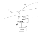
- FIG. 1 is a side view schematically showing the configuration of the virtual image display device 100 according to the first embodiment.
- the virtual image display device 100 is disposed, for example, in the dashboard or on the dashboard below the windshield 90 of the vehicle, and displays the virtual image 60 in front of the windshield 90 or the combiner.
- the projection unit 30 emits image display light based on the display image output from the control unit 20, reflects the light by the projection mirror 40, and projects the light on the windshield 90 or the combiner.
- the virtual image display device 100 reflects the projected image display light by the windshield 90 or the combiner, projects the virtual image 60 superimposed on the landscape outside the vehicle in front of the windshield, and provides it to the user.
- the virtual image display device 100 includes an image corresponding to, for example, the traveling speed of the vehicle, vehicle information such as the temperature of the engine and the remaining amount of fuel, external environment information such as the outside air temperature, and information on road signs such as the maximum speed. Generate a display image.
- the virtual image display device 100 also generates a display image including an image corresponding to current position information and route guidance information acquired from a map display device such as a navigation device mounted on a vehicle.
- the virtual image display device 100 increases or decreases the amount of information contained in the display image according to the acquired user's visual acuity, changes the size of the image corresponding to each information, generates a display image, and displays it as a virtual image.
- the virtual image display device 100 according to the embodiment described below can be used not only in vehicles but also in aircraft, game machines, entertainment facilities, etc., and can be miniaturized and used as a wearable device. You can also.
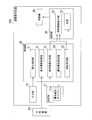
- FIG. 2 is a block diagram showing the configuration of the virtual image display device 100.
- the virtual image display device 100 includes an input unit 10, a storage unit 11, a control unit 20, a projection unit 30, and a projection mirror 40.
- the input unit 10 includes switches such as operation keys, arrow keys, and a touch panel, and receives an operation input by the user.
- the input unit 10 may be, for example, a touch panel incorporated in a display device.
- the input unit 10 may also correspond to an input by another means such as a voice input or a gesture input.
- the storage unit 11 is configured by a data storage device such as a random access memory (RAM), a flash memory, a hard disk storage device, etc., and stores a priority order table 11a described later.
- RAM random access memory
- flash memory flash memory
- hard disk storage device etc.
- the control unit 20 includes a visual acuity measurement unit 21, a display information acquisition unit 22, a display image generation unit 23, a priority setting unit 24, and a projection processing unit 25.
- the control unit 20 is constituted by, for example, a CPU, and executes the processing by the above-described units according to a computer program stored in a non-volatile memory (not shown) and various information used for the computer program.
- the visual acuity measurement unit 21 acquires the visual acuity of the user by measuring it.
- the visual acuity measurement unit 21 sequentially displays the visual acuity measurement image (for example, a Landordo ring etc.) generated by the display image generation unit 23 as a virtual image in front of the windshield 90, and the user's reply to each visual acuity measurement image By acquiring from the input unit 10, the visual acuity of the user is measured.
- a plurality of visual acuity measurement images are prepared from small to large outer dimensions, and correspond to the height of the visual acuity.
- the control unit 20 sequentially displays the vision measurement images corresponding to the visual acuity of 0.3 to 1.5 as a virtual image on the front of the windshield 90, and the user's reply to each vision measurement image is input unit 10 Get from For example, when displaying the Landordo ring as a virtual image as an image for vision measurement, the user inputs an answer from the input unit 10 as to whether the side with the notch in each Landordo ring is up, down, left or right.
- the visual acuity measurement unit 21 determines whether the user's answer to each visual acuity measurement image is correct or incorrect, and acquires the maximum visual acuity in which the correct answer is obtained as the visual acuity of the user. Vision measurement can be further enhanced by various algorithms such as trying several measurements.
- the eyesight measurement unit 21 may acquire the eyesight input by the user through the input unit 10. In this case, the user needs to know how much his or her vision is. However, even if the user knows his or her own visual acuity by means of a separate visual acuity test etc., the visual acuity changes depending on the difference in day and night and the feeling of fatigue of the eyes etc. It is preferable to perform vision measurement by reflecting a virtual image forward.
- the display information acquisition unit 22 acquires information to be displayed on the virtual image 60 from the external device 80.
- the information to be displayed includes, for example, information on the traveling speed of the vehicle, information on the vehicle such as the engine temperature and fuel consumption, information on the external environment such as the outside temperature, information on road traffic regulations such as the maximum speed, and current position information and route guidance information is there.
- the external device 80 is an electronic control device mounted on a vehicle, a map display device such as a car navigation device, a VICS receiving device for receiving road traffic information from VICS (Vehicle Information and Communication System), and a drive recorder And the like.
- the display information acquisition unit 22 acquires information on the vehicle and information on the external environment from the electronic control unit mounted on the vehicle.
- the display information acquisition unit 22 mainly acquires information on road traffic regulation, current position information and route guidance information from the map display device, but when the VICS receiver and the external imaging device are mounted on a vehicle, these are also obtained. Each piece of information may be acquired from the device of
- the display image generation unit 23 generates a display image including an image corresponding to each information input from the display information acquisition unit 22, and outputs the display image to the projection unit 30.
- FIG. 3 is a schematic view showing an example of a display image displayed as a virtual image
- FIG. 4 is a chart showing an example of the priority order table 11a.
- the display image A shown in FIG. 3 is an image having a rectangular area whose width and height directions have predetermined pixel dimensions, and image data corresponding to various information is arranged in this area.
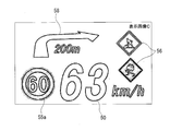
- the display image A includes a traveling speed image 50 showing the traveling speed of the vehicle, an engine information image 51 showing the engine temperature etc., a maintenance speed image 52 showing the maintenance speed of the automatic traveling control, and a collision warning of a collision against the preceding vehicle.
- a warning image 53 is included.
- Vehicle information such as traveling speed, engine information, maintenance speed, and collision warning is obtained from an electronic control unit mounted on the vehicle. Each piece of information is monitored or controlled in an electronic control device such as a speedometer system, an engine control system, an automatic travel control system, and a collision prevention control system.
- the outside air temperature image 54 a is generated based on the outside air temperature information measured by the outside air temperature sensor with which the electronic control device is provided to monitor the outside environment.
- the display image A includes a reception broadcast station image 54b as in-vehicle information. Information on the receiving station is obtained from the audio device.
- the reception broadcast station image 54b displays frequencies such as AM broadcast, FM broadcast, and television broadcast, a channel number, a broadcast station name, and the like.
- the display image A includes an image for displaying information on road traffic regulation.
- the display image A is a restriction sign image 55 such as the maximum speed image 55a and the parking prohibition image 55b, a warning sign image 56 indicating that the road is under construction or slippery, a national road number, a municipality, a direction and a distance
- the guide sign image 57 etc. which show etc. are displayed.
- Information on road signs such as restriction signs, warning signs, and guide signs included in the display image A is acquired by the display information acquisition unit 22 corresponding to the current position of the vehicle and extracted by the map display device. Further, as the information of the road sign, information of the road sign extracted by image analysis from an image captured by the external imaging device provided in the vehicle may be used.
- the display image A includes a route guidance image 58 regarding route guidance provided by the map display device.
- the map display device connects the current position and the destination based on the route setting information including the destination input by the user, the route setting condition and the like, and creates a route candidate applicable to the route setting condition based on the map data.
- the route setting condition is, for example, a condition such as a short moving time or a short distance.
- the map display device performs route guidance in real time so that the vehicle travels according to the set route selected by the user from among the created route candidates.
- the display image generation unit 23 causes the display image A to include the route guidance image 58 based on the route guidance information acquired by the display information acquisition unit 22 from the map display device.
- the route guidance image 58 shown in FIG. 3 guides turning 200 m ahead to the right.
- the display image generation unit 23 changes the arrangement of the above-described images in the display image area and changes the display size (size) in accordance with the user's visual acuity acquired by the visual acuity measurement unit 21.
- the display image generation unit 23 enlarges the display size of each image when the user's vision is low, and reduces the display size when the user's vision is high.
- the display image generation unit 23 selects an image to be included in the display image based on the priority table 11 a stored in the storage unit 11 in order to suppress an increase in the entire display image when the display size of each image is increased. Change the amount of information to generate a display image.
- the display image generation unit 23 generates a display image by increasing the amount of information when the visual acuity is high and reducing the amount of information except for information with low priority when the visual acuity is low.
- the display image generation unit 23 mutually sets each image corresponding to the high priority information in the area of the display image including the space generated by excluding the image corresponding to the low priority information. Adjust the positional relationship of to change the layout, and increase the external dimensions of each image.
- the priority order is set for each information at a stage of, for example, "low”, “medium”, and “high” as in the priority order table 11a shown in FIG.
- the display image generation unit 23 has low, medium, and high priorities shown in FIG. 4. Generate a display image that includes everything.
- the display image generation unit 23 excludes low priority. Generate a display image that includes medium and high.
- the display image generation unit 23 excludes high and low priorities. Generate a display image to include.
- the priority setting unit 24 acquires the priority that the user inputs to the input unit 10, initializes the priority table 11a, and changes it as needed.
- the priority stored in the priority table 11a may be set by default. Further, when the user inputs the priority by the input unit 10, the control unit 20 generates a display image for displaying the information name, the category, and the priority to be selected by the display image generation unit 23, and displays the virtual image 60 to display priority. It is good to be able to choose the order.
- the projection processing unit 25 performs projection processing for projecting the display image generated by the display image generation unit 23 as a virtual image.
- the projection processing unit 25 controls the luminance and display timing of an image displayed by the projection image display unit 31 described later, the luminance and the operation timing of the light source 32, and the like in the projection processing.
- the projection processing unit 25 instructs the display image generation unit 23 to output the generated display image to the projection image display unit 31 and causes the projection image display unit 31 to display the input display image. To command.
- the projection processing unit 25 also controls the display image luminance of the projection image display unit 31 and the luminance of the light source 32 based on information such as an illuminance sensor (not shown).
- the projection unit 30 accommodates an optical system (not shown) including a projection image display unit 31, a light source 32, various optical lenses, and a mirror.
- the projection unit 30 generates and displays image display light based on the display image.
- the projection image display unit 31 may be, for example, a liquid crystal on silicon (LCOS) as a reflective liquid crystal display panel, a liquid crystal display (LCD) as a transmissive liquid crystal panel, or a digital light processing DLP using a digital mirror device. ) Is used.
- the projection image display unit 31 displays the display image input from the display image generation unit 23, is irradiated with light from the light source 32, and image display light generated by the reflection or transmission thereof is transmitted to the projection mirror 40 through the optical system. Projected
- the luminance and display timing of the image displayed by the projection image display unit 31, the luminance and operation timing of the light source 32, and the like are controlled by the projection processing unit 25 as described above.
- the projection image display unit 31 may be an image display device including an element that emits light by itself, such as an organic EL (Electro Luminescence), a fluorescent display tube (Vacuum Fluorescent Display), or a light emitting diode (LED).
- the projection unit 30 may be laser light scanning by a transmissive liquid crystal or a micro electro mechanical systems (MEMS) mirror.
- MEMS micro electro mechanical systems
- the projection mirror 40 is configured by, for example, a concave mirror.
- the projection mirror 40 reflects the image display light projected from the projection unit 30 to change the direction of the image display light to the direction of the windshield 90 or the combiner.
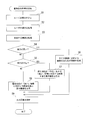
- FIG. 5 is a flowchart showing the procedure of the virtual image display process.
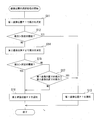
- the visual acuity measurement unit 21 of the control unit 20 measures the visual acuity of the user based on the visual acuity measurement image (for example, a Landordo ring or the like) displayed as a virtual image 60 in front of the windshield 90 (S1).
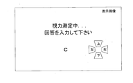
- FIG. 6 is a schematic view showing an example of a display image displayed as a virtual image at the time of vision measurement.
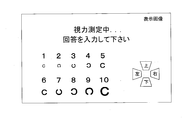
- the display image shown in FIG. 6 includes a display of a Landordo ring as a vision measurement image, that the vision is being measured, and that the user is prompted to answer.
- the user inputs the direction of the notch of the land ring by the input unit 10.
- the visual acuity measurement unit 21 outputs a signal indicating that the user's answer has been obtained from the input unit 10 to the display image generation unit 23 and the projection processing unit 25.
- the display image generation unit 23 and the projection processing unit 25 sequentially display the vision measurement image as a virtual image.
- the visual acuity measurement unit 21 determines whether the user's answer to each visual acuity measurement image is correct or incorrect, and acquires the maximum visual acuity in which the correct answer is obtained as the visual acuity of the user (S2).
- the eyesight measurement unit 21 may acquire the eyesight input by the user through the input unit 10.
- the display information acquisition unit 22 acquires information to be displayed as the virtual image 60 from the external device 80 (S3).
- the information acquired by the display information acquiring unit 22 is information on a vehicle, information on an external environment, information on road traffic regulation, current position information, route guidance information, and the like.
- the display image generation unit 23 determines whether the visual acuity measured by the visual acuity measurement unit 21 is high (S4), and when it is determined that the visual acuity is high (S4: YES), all the information acquired by the display information acquisition unit 22 A display image including the corresponding image is generated (S5). For example, when the visual acuity of the user measured by the visual acuity measurement unit 21 is 1.2 or more, the display image generation unit 23 determines that the visual acuity is high.
- the display image generated by the display image generation unit 23 is, for example, the display image A shown in FIG. 3 and is set to “low”, “medium” and “high” in the priority order in the priority order table 11 a shown in FIG. Contains each image corresponding to the
- step S4 when the visual acuity is not high and it is determined as "No" (S4: NO), the display image generation unit 23 determines whether the visual acuity measured by the visual acuity measurement unit 21 is middle (S6) . If the display image generation unit 23 determines in step S6 that the visual acuity is moderate (S6: YES), the priority order in the priority table 11a is “low” in the information acquired by the display information acquisition unit 22. A display image including an image corresponding to the information set to "medium” and "high” is generated (S7).
- FIG. 7 is a schematic view showing an example of a display image displayed as a virtual image according to the eyesight.
- the display image generation unit 23 generates, for example, a display image B illustrated in FIG. 7 when the user's visual acuity is moderate.
- An image 58 is included.
- step S6 when it is determined that the visual acuity is not moderate but "NO" (S6: NO), the display image generation unit 23 determines that the visual acuity measured by the visual acuity measurement unit 21 is low, and the display information acquisition unit 22 acquires Among the information, a display image including an image corresponding to the information set to "high” is generated except for the ones with "low” and "medium” priority in the priority table 11a (S8). In this case, the display image generation unit 23 determines, for example, that the user's eyesight is less than 0.8.
- FIG. 8 is a schematic view showing an example of a display image displayed as a virtual image according to the eyesight.
- the display image generation unit 23 generates, for example, a display image C illustrated in FIG. 8 when the user's vision is low.
- the display image C includes a traveling speed image 50 as vehicle information, a maximum speed image 55a and a warning sign image 56 as restriction information, and a route guidance image 58 as route guidance information.
- the display image generation unit 23 changes the size of each image corresponding to the information on the vehicle, the information on the external environment, the information on road traffic regulation, the current position information, the route guidance information, etc. according to the user's vision. , And the visibility of the display image can be enhanced.
- the display image generation unit 23 generates a display image by changing the amount of information based on the priority order table 11a.
- the display image generation unit 23 increases the amount of information when the visual acuity is high, and when the visual acuity is low, generates a display image excluding information with a low priority to improve the visibility of the display image. it can.
- the priority order of each information in the priority order table 11a can be changed by acquiring the priority order input to the input unit 10 by the user using the priority order setting unit 24. Therefore, the information required by the user is prioritized as a virtual image It can be displayed as 60.
- the visual acuity measurement unit 21 acquires the user's answer to the visual acuity measurement image projected forward of the windshield 90 as the virtual image 60, and determines the correctness of the user's answer to obtain the maximum visual acuity for which the correct answer is obtained. Acquire as the eyesight of the user.
- the virtual image display device 100 can obtain the visual acuity at the start of driving by measuring the visual acuity before starting the driving operation while the user is in the vehicle, and it is possible to obtain the visual acuity at the start of driving. The visibility of the display image can be enhanced according to the changing visual acuity.
- the virtual image display device 100 includes a visual acuity measurement unit 21, a display information acquisition unit 22, a display image generation unit 23, and a projection processing unit 25.
- the visual acuity measurement unit 21 measures the visual acuity of the user, and the display information acquisition unit 22 acquires information to be displayed.
- the display image generation unit 23 generates a display image in which an image corresponding to the information acquired by the display information acquisition unit 22 is displayed according to the visual acuity measured by the visual acuity measurement unit 21.
- the projection processing unit 25 performs projection processing for projecting the display image generated by the display image generation unit 23 as a virtual image. As a result, the virtual image display device 100 displays an image according to the visual acuity, so the visibility of the display image can be enhanced.
- the display image generation unit 23 changes the display dimensions of the image corresponding to the information acquired by the display information acquisition unit 22 in accordance with the visual acuity measured by the visual acuity measurement unit 21.
- the virtual image display device 100 can increase the visibility of a display image by reducing the image when the visual acuity is high and enlarging the image when the visual acuity is low.
- the display image generation unit 23 changes the amount of information included in the display image according to the visual acuity measured by the visual acuity measurement unit 21.
- the virtual image display device 100 can increase the amount of information when the visual acuity is high, and reduce the amount of information when the visual acuity is low, thereby enhancing the visibility of the display image.
- the priority setting unit 24 sets the priority of the information acquired by the display information acquisition unit 22.
- the display image generation unit 23 changes the amount of information included in the display image based on the set priority. Thereby, the virtual image display apparatus 100 can improve the visibility of a display image by generating a display image excluding information with low priority when the visual acuity is low.
- the visual acuity measurement unit 21 measures the visual acuity based on the user's answer to the visual acuity measurement image projected as a virtual image.
- the virtual image display device 100 can measure the visual acuity in the state where the user is in the vehicle. By measuring the visual acuity before starting the driving operation, it is possible to measure the visual acuity at the start of the driving.
- the vision measurement unit 21 also measures the vision at the start of driving of the vehicle.
- the virtual image display device 100 can improve the visibility of the display image according to the visual acuity at the start of driving by measuring the visual acuity before the user starts driving.
- the display image generation unit 23 generates a display image based on the user's input to the display image of the color sample projected as a virtual image.
- the virtual image display device 100 can further improve the visibility by changing the color of the image to be displayed on the display image to generate the display image.
- the virtual image display method further includes a vision measurement step, a display information acquisition step, a display image generation step, and a projection processing step.
- the visual acuity measurement step measures the visual acuity of the user, and the display information acquisition step acquires information to be displayed.
- the display image generation step generates a display image which displays an image corresponding to the information acquired by the display information acquisition step according to the visual acuity measured by the visual acuity measurement step.
- the projection processing step performs projection processing for projecting the display image generated in the display image generation step as a virtual image. According to this virtual image display method, since the image according to the visual acuity is displayed, the visibility of the display image can be enhanced.
- the virtual image display program also causes the computer to execute the vision measurement step, the display information acquisition step, the display image generation step, and the projection processing step.
- the visual acuity measurement step measures the visual acuity of the user, and the display information acquisition step acquires information to be displayed.
- the display image generation step generates a display image which displays an image corresponding to the information acquired by the display information acquisition step according to the visual acuity measured by the visual acuity measurement step.
- the projection processing step performs projection processing for projecting the display image generated in the display image generation step as a virtual image. According to this virtual image display program, an image according to the eyesight is displayed, so that the visibility of the display image can be enhanced.
- FIG. 9 is a side view schematically showing the configuration of the virtual image display device 100 according to the second embodiment.
- the virtual image display device 100 is disposed, for example, in a dashboard or dashboard below the windshield 90 of the vehicle, and displays the virtual image 60 at the first virtual image position P1 or the second virtual image position P2 in front of the windshield 90 or the combiner. Do.
- the second virtual image position P2 is at a position different from the first virtual image position P1 and is farther from the first virtual image position P1.
- the projection unit 30 emits image display light based on the display image output from the control unit 20, reflects the light by the projection mirror 40, and projects the light on the windshield 90 or the combiner.
- the virtual image display device 100 reflects the projected image display light by the windshield 90 or the combiner, projects the virtual image 60 superimposed on the landscape outside the vehicle in front of the windshield, and provides it to the user.
- the virtual image display device 100 includes an image corresponding to, for example, the traveling speed of the vehicle, vehicle information such as the temperature of the engine and the remaining amount of fuel, external environment information such as the outside air temperature, and information on road signs such as the maximum speed. Generate a display image.
- the virtual image display device 100 also generates a display image including an image corresponding to current position information and route guidance information acquired from a map display device such as a navigation device mounted on a vehicle.
- the virtual image display device 100 increases or decreases the amount of information contained in the display image according to the measured visual acuity of the user, changes the size of the image corresponding to each information, generates a display image, and displays it as a virtual image.
- the virtual image display device 100 according to the embodiment described below can be used not only in vehicles but also in aircraft, game machines, entertainment facilities, etc., and can be miniaturized and used as a wearable device. You can also.
- FIG. 10 is a block diagram showing the configuration of the virtual image display device 100.
- the virtual image display device 100 includes an input unit 10, a storage unit 11, a control unit 20, a projection unit 30, and a projection mirror 40.
- the configuration of the input unit 10 and the storage unit 11 is the same as that of the first embodiment, and the description will be omitted for the sake of brevity.
- the control unit 20 includes a virtual image position selection unit 120, a visual acuity measurement unit 121, a display information acquisition unit 22, a display image generation unit 23, a priority setting unit 24, and a projection processing unit 25.
- the control unit 20 is constituted by, for example, a CPU, and executes the processing by the above-described units according to a computer program stored in a non-volatile memory (not shown) and various information used for the computer program.
- the display information acquisition unit 22, the display image generation unit 23, the priority setting unit 24, the projection processing unit 25, the projection unit 30, and the projection mirror 40 in the control unit 20 are the same as those in Embodiment 1 except for the following description. It has the same configuration as each part denoted by the reference numeral and functions in the same manner.
- the virtual image position selection unit 120 sets the display position of the virtual image at a position different from the first virtual image position P1 or the first virtual image position P1, and at the second virtual image position P2 which is farther than the first virtual image position P1. One of them is selected (see FIG. 9).
- the display position of the virtual image selected by the virtual image position selection unit 120 may be two or more plural positions, or may be any position that can be changed continuously, for example, from P1 to P2.
- the display position of the virtual image sets, for example, the first virtual image position P1 to a position at a distance of 3 m from the viewpoint position of the user and the second virtual image position P2 to a position of 5 m, but is not limited thereto.
- the visual acuity measurement unit 121 measures the visual acuity of the user at the display position of the virtual image selected by the virtual image position selection unit 120.
- the visual acuity measurement image (for example, a Landordo ring etc.) generated by the display image generation unit 23 is sequentially displayed as a virtual image at the display position (first virtual image position P1 or second virtual image position P2) of the virtual image in front of the windshield 90. Ru.
- the visual acuity measurement unit 121 measures the visual acuity of the user by acquiring the user's answer to each visual acuity measurement image from the input unit 10.
- a plurality of visual acuity measurement images are prepared from small to large outer dimensions, and correspond to the height of the visual acuity.
- the control unit 20 sequentially displays the vision measurement images corresponding to the visual acuity of 0.3 to 1.5 as a virtual image on the front of the windshield 90, and the user's reply to each vision measurement image is input unit 10 Get from For example, when displaying the Landordo ring as a virtual image as an image for vision measurement, the user inputs an answer from the input unit 10 as to whether the side with the notch in each Landordo ring is up, down, left, or right.
- the visual acuity measurement unit 121 determines whether the user's answer to each visual acuity measurement image is correct or incorrect, and acquires the maximum visual acuity in which the correct answer is obtained as the visual acuity of the user. Vision measurement can be further enhanced by various algorithms such as trying several measurements.
- the visual acuity measurement unit 121 selects the other display position when the user's visual acuity measured at the display position of either the first virtual image position P1 or the second virtual image position P2 is low and is equal to or less than a predetermined threshold. Is output to the virtual image position selection unit 120.
- the visual acuity measurement unit 121 measures the visual acuity of the user at the other display position, and if higher than a predetermined threshold, the virtual image position selection unit 120 keeps the other display position selected.
- the visual acuity measurement unit 121 selects the display position with the better visual acuity from the first virtual image position P1 or the second virtual image position P2.
- a signal indicating selection is output to the virtual image position selection unit 120.
- the visual acuity measurement unit 121 causes the virtual image position selection unit 120 to sequentially select the first virtual image position P1 and the second virtual image position P2, measures the visual acuity at both display positions, and displays the display position with better visual acuity.
- a signal indicating selection may be output to the virtual image position selection unit 120.
- FIG. 11 is a schematic view for explaining the size of the vision measurement image.
- the display image generation unit 23 displays the sizes of the vision measurement images displayed at the first virtual image position P1 and the second virtual image position P2 for the same visual acuity in different dimensions according to the distance from the user's viewpoint position. Generate an image.
- the size of the vision measurement image increases in size as the distance from the user's viewpoint position increases.
- the user's viewpoint position has individual differences, it is preferable to allow a certain degree of error to define a typical position. Further, the distance from the viewpoint position of the user may be adjusted for each user.
- the external dimension of the visual acuity measurement image displayed at the second virtual image position P2 is a ratio (L2 / L1) of the distance L2 from the viewpoint position to the second virtual image position P2 to the distance L1 from the first virtual image position P1. It is a value obtained by multiplying the outer dimension of the vision measurement image displayed at the virtual image position P1. Thereby, it is possible to generate a vision measurement image for measuring the same vision at the first virtual image position P1 and the second virtual image position P2.
- the external dimensions of the vision measurement image displayed at the second virtual image position P2 are the first virtual image It may be twice the outer dimension of the vision measurement image displayed at the position P1.
- the display information acquisition unit 22, the display image generation unit 23, and the priority setting unit 24 are configured in the same manner as the units denoted by the same reference numerals described in the first embodiment, and the display image shown as an example in FIG.
- the priority order table 11a generated and shown as an example in FIG. 4 is used.
- the projection processing unit 25 performs a projection process of projecting the display image generated by the display image generation unit 23 as a virtual image at the display position selected by the virtual image position selection unit 120.
- the projection processing unit 25 moves the position of the image (intermediate formed image) displayed by the projection image display unit 31 described later (intermediate formed image) closer to or away from the projection mirror 40 or between the intermediate formed image and the projection mirror 40.
- the display position of the virtual image is changed to the first virtual image position P ⁇ b> 1 or the second virtual image position P ⁇ b> 2 by approaching or separating the position of the installed lens.
- a known method can be used to change the display position of the virtual image to the first virtual image position P1 or the second virtual image position P2 or a position between them, and therefore the description is omitted for the sake of brevity. Do.
- the projection processing unit 25 controls the luminance and display timing of an image displayed by the projection image display unit 31, the luminance and operation timing of the light source 32, and the like in the projection processing.
- the projection processing unit 25 instructs the display image generation unit 23 to output the generated display image to the projection image display unit 31 and causes the projection image display unit 31 to display the input display image. To command.
- the projection processing unit 25 also controls the display image luminance of the projection image display unit 31 and the luminance of the light source 32 based on information such as an illuminance sensor (not shown).
- the projection unit 30 accommodates an optical system (not shown) including a projection image display unit 31, a light source 32, various optical lenses, mirrors and the like, and is configured the same as the units denoted by the same reference numerals described in the first embodiment. It is done.
- the projection unit 30 causes the projection image display unit 31 to display the display image input from the display image generation unit 23, irradiates the light from the light source 32, and transmits the image display light generated by the reflection or transmission through the optical system. It projects on the projection mirror 40.
- the projection image display unit 31 has a drive system for moving the position of the intermediate formed image or the position of the lens disposed between the intermediate formed image and the projection mirror 40 closer to or away from the projection mirror 40. , And is controlled by the projection processing unit 25.
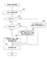
- FIG. 12 is a flow chart showing the procedure of selection processing of the virtual image position. It is assumed that the virtual image position selection unit 120 of the control unit 20 selects the first virtual image position P1 at the start time of the selection process of the virtual image position.
- the visual acuity measurement unit 121 measures the visual acuity of the user based on the visual acuity measurement image (for example, a Landordo ring or the like) displayed as a virtual image 60 at the first virtual image position P1 in front of the windshield 90 (S11).
- the visual acuity measurement image for example, a Landordo ring or the like
- FIG. 6 An example of a display image displayed as a virtual image at the time of vision measurement is as shown in FIG.
- the display image shown in FIG. 6 includes a display of a Landordo ring as a vision measurement image, that the vision is being measured, and that the user is prompted to answer.
- the user inputs the direction of the notch of the land ring by the input unit 10.
- the visual acuity measurement unit 121 outputs a signal indicating that the user's answer has been obtained from the input unit 10 to the display image generation unit 23 and the projection processing unit 25.
- the display image generation unit 23 and the projection processing unit 25 sequentially display the vision measurement image as a virtual image.
- the visual acuity measurement unit 121 determines whether the user's answer to each visual acuity measurement image is correct or incorrect, and sets the maximum visual acuity for which the correct answer is obtained as the visual acuity of the user.
- the eyesight measurement unit 121 may obtain the eyesight input by the user through the input unit 10.
- the visual acuity measurement unit 121 determines whether the measured visual acuity is higher than a predetermined threshold (for example, 1.0) (S12), and when higher than the predetermined threshold (S12: YES), displays the first virtual image position P1. The position is selected (S13), and the process ends.
- a predetermined threshold for example, 1.0
- the visual acuity measurement unit 121 causes the virtual image position selection unit 120 to select the second virtual image position P2 and measures the user's visual acuity (S12). S14).
- the visual acuity measurement unit 121 determines whether the measured visual acuity is higher than a predetermined threshold (for example, 1.0) (S15). If the measured visual acuity is higher than the predetermined threshold (S15: YES), the second virtual image position P2 is displayed The position is selected (S16), and the process ends. In step S15, when the measured visual acuity is equal to or less than the predetermined threshold (S15: NO), the visual acuity measurement unit 121 determines whether the visual acuity at the first virtual image position P1 is higher than the visual acuity at the second virtual image position P2. It is determined (S17).
- a predetermined threshold for example, 1.0
- the visual acuity measurement unit 121 proceeds to step S13 and selects the first virtual image position P1 as the display position. , End the process. Further, when the visual acuity at the first virtual image position P1 is less than the visual acuity at the second virtual image position P2 (S17: NO), the visual acuity measurement unit 121 proceeds to step S16 and selects the second virtual image position P2 as the display position And end the process.
- the virtual image position selection unit 120 can select the display position of the first virtual image position P1 or the second virtual image position P2 which improves the vision. Further, the visual acuity measurement unit 121 can obtain the visual acuity at the display position of the virtual image selected by the virtual image position selection unit 120 by measurement. Further, the display image generation unit 23 sets the size of the vision measurement image to be displayed at the first virtual image position P1 and the second virtual image position P2 for the same visual acuity in different dimensions according to the distance from the user's viewpoint position. Generate an image to be displayed. This makes it possible to compare the user's vision at the first virtual image position P1 and the second virtual image position P2.
- FIG. 13 is a flowchart showing the procedure of virtual image display processing.
- the virtual image position selection unit 120 in the control unit 20 selects the first virtual image position P1 or the second virtual image position P2 by the above-described selection process of the virtual image position.
- the visual acuity measurement unit 121 measures the visual acuity of the user by the selection processing of the virtual image position described above.
- the display information acquisition unit 22 acquires information to be displayed as the virtual image 60 from the external device 80 (S21).
- the information acquired by the display information acquiring unit 22 is information on a vehicle, information on an external environment, information on road traffic regulation, current position information, route guidance information, and the like as described in the first embodiment.
- step S22 to step S27 is equivalent to the processing from step S4 to step S9 in FIG. 5 of the first embodiment, and the description will be omitted for the sake of simplification of the description.
- the display images shown in FIG. 3, FIG. 7 and FIG. 8 are generated according to the user's visual acuity.
- the display image generation unit 23 changes the size of each image corresponding to the information on the vehicle, the information on the external environment, the information on road traffic regulation, the current position information, the route guidance information, etc. according to the user's vision. , And the visibility of the display image can be enhanced.
- the display image generation unit 23 generates a display image by changing the amount of information based on the priority order table 11a.
- the display image generation unit 23 increases the amount of information when the visual acuity is high, and when the visual acuity is low, generates a display image excluding information with a low priority to improve the visibility of the display image. it can.
- the priority order of each information in the priority order table 11a can be changed by acquiring the priority order input to the input unit 10 by the user using the priority order setting unit 24. Therefore, the information required by the user is prioritized as a virtual image It can be displayed as 60.
- the visual acuity measurement unit 121 acquires the user's answer to the visual acuity measurement image projected forward of the windshield 90 as the virtual image 60, and determines the correctness of the user's answer to obtain the maximum visual acuity for which the correct answer is obtained. Acquire as the eyesight of the user.
- the virtual image display device 100 can obtain the visual acuity at the start of driving by measuring the visual acuity before starting the driving operation while the user is in the vehicle, and it is possible to obtain the visual acuity at the start of driving. The visibility of the display image can be enhanced according to the changing visual acuity.
- the virtual image display device 100 includes a virtual image position selection unit 120, a visual acuity measurement unit 121, a display information acquisition unit 22, a display image generation unit 23, and a projection processing unit 25.
- the virtual image position selection unit 120 selects the display position of the virtual image as either the first virtual image position P1 or the second virtual image position P2 different from the first virtual image position P1.
- the visual acuity measurement unit 121 measures the visual acuity of the user based on the user's answer to the visual acuity measurement image projected as a virtual image at the display position selected by the virtual image position selection unit 120.
- the display information acquisition unit 22 acquires information to be displayed.
- the display image generation unit 23 generates a display image that displays an image corresponding to the information acquired by the display information acquisition unit 22 in a size according to the visual acuity acquired by the visual acuity measurement unit 121.
- the projection processing unit 25 performs projection processing to project the display image generated by the display image generation unit 23 as a virtual image on the display position selected by the virtual image position selection unit 120. Thereby, the virtual image display device 100 can select the perspective of the display position of the virtual image, and can improve the user's visibility to the virtual image.
- the sizes of the vision measurement images displayed at the first virtual image position P1 and the second virtual image position P2 have different dimensions according to the distance from the user's viewpoint position. It becomes possible to compare the visual acuity of the user at two virtual image positions P2.
- the visual acuity measurement image has a larger dimension as the distance from the user's viewpoint position is longer, so that the visual acuity of the user at the first virtual image position P1 and the second virtual image position P2 can be compared.
- the virtual image position selection unit 120 selects the other display position when the user's visual acuity measured at either the first virtual image position P1 or the second virtual image position P2 is less than or equal to a predetermined threshold.
- the visual acuity measurement unit 121 measures the visual acuity of the user based on the user's answer to the visual acuity measurement image projected as a virtual image at the other display position. Thereby, when the visual acuity at the first virtual image position P1 is less than a predetermined threshold, the visual acuity of the user at the second virtual image position P2 is measured, and either the first virtual image position P1 or the second virtual image position P2 is a virtual image. It can be compared and determined whether it should be the display position.
- the display image generation unit 23 changes the amount of information included in the display image according to the visual acuity acquired by the visual acuity measurement unit 121.
- the virtual image display device 100 can increase the amount of information when the visual acuity is high, and reduce the amount of information when the visual acuity is low, thereby enhancing the visibility of the display image.
- the priority setting unit 24 sets the priority of the information acquired by the display information acquisition unit 22.
- the display image generation unit 23 changes the amount of information included in the display image based on the set priority. Thereby, the virtual image display apparatus 100 can improve the visibility of a display image by generating a display image excluding information with low priority when the visual acuity is low.
- the virtual image display method includes a virtual image position selection step, a visual acuity measurement step, a display information acquisition step, a display image generation step, and a projection processing step.
- the virtual image position selecting step selects the display position of the virtual image as either the first virtual image position P1 or the second virtual image position P2 different from the first virtual image position P1.
- the vision measurement step measures the user's vision based on the user's answer to the vision measurement image projected as a virtual image at the display position selected by the virtual image position selection step.
- the display information acquisition step acquires information to be displayed.
- the display image generation step generates a display image which displays an image corresponding to the information acquired in the display information acquisition step in a size corresponding to the visual acuity acquired in the visual acuity measurement step.
- the projection processing step performs projection processing of projecting the display image generated in the display image generation step as a virtual image on the display position selected in the virtual image position selection step. According to this virtual image display method, it is possible to select the perspective of the display position of the virtual image and to improve the user's visibility to the virtual image.
- the virtual image display program causes the computer to execute a virtual image position selection step, a visual acuity measurement step, a display information acquisition step, a display image generation step and a projection processing step.
- the virtual image position selecting step selects the display position of the virtual image as either the first virtual image position P1 or the second virtual image position P2 different from the first virtual image position P1.
- the vision measurement step measures the user's vision based on the user's answer to the vision measurement image projected as a virtual image at the display position selected by the virtual image position selection step.
- the display information acquisition step acquires information to be displayed.
- the display image generation step generates a display image which displays an image corresponding to the information acquired in the display information acquisition step in a size corresponding to the visual acuity acquired in the visual acuity measurement step.
- the projection processing step performs projection processing of projecting the display image generated in the display image generation step as a virtual image on the display position selected in the virtual image position selection step. According to this virtual image display program, it is possible to select the perspective of the display position of the virtual image and to improve the user's visibility to the virtual image.
- the display image generation unit 23 may set the color of the image corresponding to each information included in the display image based on the hue, lightness and saturation of the color input by the user.
- the virtual image display device 100 displays a color setting screen on which a color sample of hue, lightness and saturation is displayed as a virtual image, and changes the color of each image displayed on the display image based on color setting information input by the user. .
- the color sample shall be displayed by changing the hue, lightness and saturation continuously or intermittently and can be selected by the user.
- the color sample is displayed by changing from a specific color (for example, blue) to another specific color (for example, red), and can be selected by the user.
- the display image generation unit 23 changes the image corresponding to each piece of information so as to be corrected by the selected color.
- the user can set, for example, the display image in the daytime to be strong in blue and the display image in the nighttime to be strong in red according to the preference of the color.
- the virtual image display device 100 can further enhance the visibility by generating a display image by changing the color of the image displayed on the display image.
- the user may store the color setting information of the user in one or more types in the storage unit 11 so that the user can call and use the color setting information. In this case, a plurality of users can use the storage unit 11 to store color setting information having high visibility of the image for the user.
- the visual acuity measurement images are displayed as virtual images one by one at the time of measuring the visual acuity of the user, but a plurality of visual acuity measurement images may be displayed.
- FIG. 14 is a schematic view showing an example of a display image at the time of visual acuity measurement in the modification.
- the display image shown in FIG. 14 includes a plurality of Landdod rings as visual acuity measurement images, a display indicating that visual acuity measurement is in progress, and a message prompting the user to answer.
- the user selects one of the plurality of land circles and inputs the direction of the notch through the input unit 10.
- the vision measuring unit 21 determines whether the user's answer to each vision measurement image is correct or not, and the correct answer is obtained. Get your eyesight as your eyesight.
- the virtual image display device 100 projects the display image on the windshield 90. However, the virtual image display device 100 may project the display image on the combiner.
- FIG. 15 is a side view schematically showing the configuration of a virtual image display device 100 according to a modification.
- the virtual image display device 100 projects the display image on the windshield 90. However, the virtual image display device 100 may project the display image on the combiner.
- FIG. 16 is a side view schematically showing the configuration of a virtual image display device 100 according to a modification.
- the virtual image display device 100 is disposed, for example, in a dashboard below the windshield 90 of the vehicle or on the dashboard, and displays a virtual image 60 in front of the combiner 41.
- the projection unit 30 emits the image display light based on the display image output from the control unit 20, reflects the light by the projection mirror 40, and projects the light on the combiner 41.
- the combiner 41 is a half mirror and is disposed on the inner side of the windshield 90.
- the user recognizes the image in which the virtual image 60 is superimposed on the landscape outside the vehicle viewed through the windshield 90. As a result, the user can observe the virtual image 60 through the windshield 90, and thus can obtain information while moving the sight line during driving operation.
- 21 vision measurement unit 22 display information acquisition unit 23 display image generation unit 24 priority setting unit, 25 projection processing unit, 100 virtual image display devices, 120 virtual image position selection unit, 121 vision measurement unit.
- the present invention is applicable not only to in-vehicle applications but also to virtual image display devices used in aircraft, game machines, entertainment facilities and the like.
Landscapes
- Engineering & Computer Science (AREA)
- Combustion & Propulsion (AREA)
- Transportation (AREA)
- Mechanical Engineering (AREA)
- Chemical & Material Sciences (AREA)
- Physics & Mathematics (AREA)
- General Physics & Mathematics (AREA)
- Theoretical Computer Science (AREA)
- Computer Hardware Design (AREA)
- Optics & Photonics (AREA)
- General Engineering & Computer Science (AREA)
- Software Systems (AREA)
- Computer Graphics (AREA)
- Human Computer Interaction (AREA)
- Controls And Circuits For Display Device (AREA)
- Eye Examination Apparatus (AREA)
Abstract
虚像表示装置(100)は、視力測定部(21)、表示情報取得部(22)、表示画像生成部(23)および投射処理部(25)を備える。視力測定部(21)はユーザの視力を測定し、表示情報取得部(22)は表示する情報を取得する。表示画像生成部(23)は、表示情報取得部(22)により取得した情報に対応する画像を、視力測定部(21)により測定した視力に応じて表示する表示画像を生成する。投射処理部(25)は、表示画像生成部(23)により生成した表示画像を虚像として投射する投射処理を行う。
Description
本発明は、虚像表示装置に関する。
車両に搭載されるヘッドアップディスプレイ等の虚像表示装置は、車外から入る光を透過すると共に、車内に配置された光学ユニットから投射された表示画像を車両のフロントガラスなどに反射させることにより、車外の風景に重畳する虚像を表示する。虚像表示装置は、車外の景色を視認しているユーザが視線や焦点をほとんど変化させることなく光学ユニットから投射された画像の情報を認識することができる。
虚像表示装置が表示する表示画像の情報量が多くなると、表示画像に含まれる個々の画像が細かくなり、ユーザの視力によっては視認性が低下する。特許文献1には、車両に乗車しながら運転者の視覚状態を判断することができる表示制御装置が開示されている。この表示制御装置は、視力測定に用いるランドルド環を表示する表示装置からユーザのアイポイントまでの距離に応じて、運転操作に必要な法定視力に相当するランドルド環の大きさを演算し、該ランドルド環を表示する。ユーザは、表示されたランドルド環の切欠き方向が認識できれば、法定視力を有していることを把握できる。
特許文献1に記載の表示制御装置では、ユーザの視力が法定視力を有していることを把握できるが、視力が法定視力を有するものの比較的に低い場合に、車両の内外に表示される細かい画像への視認性を高めることはできない。
とくに虚像表示装置は、車外を視認しているユーザが視線や焦点をほとんど変化させることなく虚像を認識することができるため、表示画像により多くの情報を含ませる傾向にあり、ユーザの視力が低い場合には表示画像の視認性が低くなってしまう。
第1発明は、斯かる事情に鑑みてなされたものであり、その目的とするところは、ユーザの視力に応じて画像を表示し、視認性を高めることができる虚像表示装置を提供することにある。
また特許文献1に記載の表示制御装置では、ユーザの視力が法定視力を有していることを把握できるが、車両の内外に表示される画像に対して、遠視または近視によって視認性に差異が生じる場合への対処にはならない。
とくに虚像表示装置は、車外を視認しているユーザが視線や焦点をほとんど変化させることなく虚像を認識することができるため、表示画像により多くの情報を含ませる傾向にあり、虚像の表示位置によっては遠視または近視のために視認性が低下してしまうという問題点があった。
第2発明は、斯かる事情に鑑みてなされたものであり、その目的とするところは、虚像の表示位置の遠近を選択し、視認性を高めることができる虚像表示装置を提供することにある。
第1の実施形態のある態様の虚像表示装置は、ユーザの視力を測定する視力測定部と、表示する情報を取得する表示情報取得部と、前記表示情報取得部により取得した情報に対応する画像を、前記視力測定部により測定した視力に応じて表示する表示画像を生成する表示画像生成部と、前記表示画像生成部により生成した表示画像を虚像として投射する投射処理を行う投射処理部と、を備える。
第2の実施形態のある態様の虚像表示装置は、虚像の表示位置を第1虚像位置、または前記第1虚像位置とは異なる第2虚像位置のいずれかに選択する虚像位置選択部と、前記虚像位置選択部により選択された表示位置に虚像として投射される視力測定用画像に対するユーザの回答に基づいて、ユーザの視力を測定する視力測定部と、表示する情報を取得する表示情報取得部と、前記表示情報取得部により取得した情報に対応する画像を、前記視力測定部により取得した視力に応じた大きさで表示する表示画像を生成する表示画像生成部と、前記表示画像生成部により生成した表示画像を前記虚像位置選択部により選択された表示位置に虚像として投射する投射処理を行う投射処理部と、を備える。
なお、以上の構成要素の任意の組合せ、本実施形態の表現を方法、装置、システム、記録媒体、コンピュータプログラムなどの間で変換したものもまた、実施形態の態様として有効である。
第1の実施形態によれば、ユーザの視力に応じて画像を表示し、視認性を高めることができる。
第2の実施形態によれば、虚像の表示位置の遠近を選択し、視認性を高めることができる。
以下、各図面に示される同一または同等の構成要素、部材には、同一の符号を付するものとし、適宜重複した説明は省略する。また、各図面における部材の寸法は、理解を容易にするために適宜拡大、縮小して示される。また、各図面において実施の形態を説明する上で重要ではない部材の一部は省略して表示する。
第1発明を好適な実施の形態をもとに図1から図8を参照しながら説明する。
(実施形態1)
図1は、実施形態1に係る虚像表示装置100の構成を模式的に示す側面図である。虚像表示装置100は、例えば車両のフロントガラス90の下方におけるダッシュボード内またはダッシュボード上に配置され、フロントガラス90またはコンバイナの前方に虚像60を表示する。虚像表示装置100は、制御部20から出力される表示画像に基づいて投射部30が画像表示光を出射し、投射鏡40で反射してフロントガラス90またはコンバイナに投射する。虚像表示装置100は、投射した画像表示光がフロントガラス90またはコンバイナによって反射され、車外の風景に重畳される虚像60をフロントガラスの前方に映し、ユーザに提供する。
図1は、実施形態1に係る虚像表示装置100の構成を模式的に示す側面図である。虚像表示装置100は、例えば車両のフロントガラス90の下方におけるダッシュボード内またはダッシュボード上に配置され、フロントガラス90またはコンバイナの前方に虚像60を表示する。虚像表示装置100は、制御部20から出力される表示画像に基づいて投射部30が画像表示光を出射し、投射鏡40で反射してフロントガラス90またはコンバイナに投射する。虚像表示装置100は、投射した画像表示光がフロントガラス90またはコンバイナによって反射され、車外の風景に重畳される虚像60をフロントガラスの前方に映し、ユーザに提供する。
虚像表示装置100は、例えば車両の走行速度、エンジンの温度および燃料の残量等の車両情報、外気温などの外部環境情報、および最高速度等の道路標識に関する情報、等に対応する画像を含む表示画像を生成する。また虚像表示装置100は、車両に搭載されたナビゲーション装置等の地図表示装置から取得した現在位置情報およびルート案内情報に対応する画像を含む表示画像を生成する。
虚像表示装置100は、取得したユーザの視力に応じて、表示画像に含まれる情報量を増減し、各情報に対応する画像の大きさを変更して表示画像を生成し、虚像として表示する。以下に説明する実施形態に係る虚像表示装置100は、車載用のものに限られず、航空機やゲーム機、娯楽施設等においても利用することができるとともに、小型化されてウェアラブルな装置として利用することもできる。
図2は、虚像表示装置100の構成を示すブロック図である。虚像表示装置100は、入力部10、記憶部11、制御部20、投射部30および投射鏡40を備える。入力部10は、操作キー、十字キー、タッチパネル等のスイッチから構成されており、ユーザによる操作入力を受け付ける。入力部10は、例えば、ディスプレイ装置に組み込まれたタッチパネルであってもよい。また、入力部10は、操作入力の他、音声入力やジェスチャ入力等の別手段による入力にも対応していてもよい。記憶部11は、RAM(Random Access Memory)、フラッシュメモリ、ハードディスク記憶装置等のデータ記憶装置によって構成されており、後述する優先順位テーブル11aを記憶する。
制御部20は、視力測定部21、表示情報取得部22、表示画像生成部23、優先順位設定部24および投射処理部25を有する。制御部20は、例えばCPUなどによって構成され、不揮発性メモリ(図示略)に格納されたコンピュータプログラム、およびコンピュータプログラムに用いる各種情報に従って、上述の各部による処理を実行する。
制御部20において視力測定部21は、ユーザの視力を測定することによって取得する。視力測定部21は、表示画像生成部23によって生成される視力測定用画像(例えばランドルド環など)が、順次、虚像としてフロントガラス90の前方に表示され、各視力測定用画像に対するユーザの回答を入力部10から取得することによって、ユーザの視力を測定する。
視力測定用画像は、例えば外形寸法が小さいものから大きいものまで複数個が用意されており、視力の高低に対応する。制御部20は、例えば視力0.3~1.5までの視力に対応する視力測定用画像を順次虚像としてフロントガラス90の前方に表示し、各視力測定用画像に対するユーザの回答を入力部10から取得する。例えば視力測定用画像としてランドルド環を虚像として表示する場合、各ランドルド環における切欠きのある側が上下左右のいずれであるかの回答をユーザが入力部10により入力し、視力測定部21で各回答を取得する。視力測定部21は、各視力測定用画像に対するユーザの回答の正誤を判定し、正答が得られた最大の視力をユーザの視力として取得する。視力測定は、数回の測定を試行するなど種々のアルゴリズムによって更に測定精度を高めることができる。
また、視力測定部21は、入力部10によりユーザが入力した視力を取得するようにしてもよい。この場合、ユーザが自己の視力が幾らであるかを知っている必要がある。但し、ユーザが別途の視力検査等によって自己の視力を知っていたとしても、昼夜の違いや、目などの疲労感によっても視力が変わるため、車両の使用時に上述のように実際にフロントガラスの前方に虚像を映して視力測定を実施することが好ましい。
表示情報取得部22は、虚像60に表示する情報を外部装置80から取得する。表示する情報は、例えば車両の走行速度、エンジン温度および燃費等の車両に関する情報、外気温などの外部環境に関する情報、最高速度等の道路交通規制に関する情報、並びに現在位置情報およびルート案内情報等である。外部装置80は、車両に搭載された電子制御装置、カーナビゲーション装置等の地図表示装置、VICS(登録商標)(Vehicle Information and Communication System)からの道路交通情報を受信するVICS受信装置、およびドライブレコーダ等の車外撮像装置などである。
表示情報取得部22は、車両に関する情報および外部環境に関する情報を車両に搭載された電子制御装置から取得する。また表示情報取得部22は、道路交通規制に関する情報、現在位置情報およびルート案内情報を主として地図表示装置から取得するが、VICS受信装置および車外撮像装置が車両に搭載されている場合には、これらの装置から各情報を取得するようにしてもよい。
表示画像生成部23は、表示情報取得部22から入力された各情報に対応する画像を含む表示画像を生成し、投射部30へ出力する。図3は虚像として表示される表示画像の一例を示す模式図であり、図4は優先順位テーブル11aの一例を示す図表である。図3に示す表示画像Aは、幅および高さ方向を所定のピクセル寸法とする長方形状の領域を有する画像であり、この領域内に各種情報に対応する画像データが配置されている。
表示画像Aには、車両の走行速度を示す走行速度画像50、エンジン温度等を示すエンジン情報画像51、自動走行制御の維持速度を示す維持速度画像52、および前方車両への衝突を警告する衝突警告画像53が含まれている。走行速度、エンジン情報、維持速度および衝突警告等の車両情報は、車両に搭載された電子制御装置から取得される。各情報は、速度メーター系、エンジン制御系、自動走行制御系、および衝突防止制御系等の電子制御装置において、モニターまたは制御されている。また、外気温画像54aは、電子制御装置が外部環境をモニターするために備える外気温センサによって計測された外気温情報に基づいて生成される。
また表示画像Aには、車内情報として受信放送局画像54bが含まれている。受信放送局の情報は、オーディオ装置から取得される。受信放送局画像54bは、AM放送、FM放送およびテレビ放送などの周波数、チャンネル番号および放送局名などを表示する。
また表示画像Aには、道路交通規制に関する情報を表示する画像が含まれている。例えば、表示画像Aは、最高速度画像55aおよび駐車禁止画像55bなどの規制標識画像55、道路が工事中であることや滑り易いことを示す警戒標識画像56、国道番号、市町村、並びに方面および距離などを示す案内標識画像57等を表示する。表示画像Aに含まれる規制標識、警戒標識および案内標識等の道路標識の情報は、車両の現在位置に対応して地図表示装置が抽出したものを表示情報取得部22において取得する。また道路標識の情報として、車両に備えた車外撮像装置によって撮像された画像から画像解析によって抽出される道路標識の情報を用いるようにしてもよい。
また表示画像Aには、地図表示装置が提供するルート案内に関するルート案内画像58が含まれている。地図表示装置は、ユーザが入力した目的地、経路設定条件等を含む経路設定情報に基づいて、現在位置と目的地を結び、経路設定条件に当てはまるルートの候補を地図データに基づいて作成する。経路設定条件は、例えば移動時間が短い、距離が短い等の条件である。地図表示装置は、作成したルート候補の中からユーザが選択した設定ルートに従って車両が走行するように、リアルタイムでルート案内を行う。表示画像生成部23は、表示情報取得部22により地図表示装置から取得したルート案内情報に基づいてルート案内画像58を表示画像Aに含ませる。尚、図3に示すルート案内画像58は、200m先で右折することを案内している。
また、図3に示す表示画像Aには含まれていないが、VICSが提供する道路交通情報をVICS受信装置から取得し、渋滞情報画像、および道路工事等による通行規制画像などを表示してもよい。
表示画像生成部23は、視力測定部21で取得されたユーザの視力に応じて、上述の各画像の表示画像の領域内における配置を変更するとともに、表示寸法(大きさ)を変更する。表示画像生成部23は、ユーザの視力が低い場合には各画像の表示寸法を大きくし、高い場合には小さくする。表示画像生成部23は、各画像の表示寸法を大きくした場合に表示画像全体が大きくなることを抑制するため、記憶部11に記憶した優先順位テーブル11aに基づいて表示画像に含ませる画像を選択し、情報量を変更して表示画像を生成する。表示画像生成部23は、視力が高い場合には情報量を多くし、視力が低い場合には優先順位の低い情報を除いて情報量を少なくして表示画像を生成する。表示画像生成部23は、視力が低い場合には、優先順位の低い情報に対応する画像を除くことで生じるスペースを含む表示画像の領域内において、優先順位の高い情報に対応する各画像の相互の位置関係を調整して配置変更し、各画像の外形寸法を大きくする。
優先順位は、図4に示す優先順位テーブル11aのように、各情報に対して、例えば「低い」、「中位」および「高い」等の段階で設定する。表示画像生成部23は、視力測定部21により取得したユーザの視力が高い場合(例えば、視力1.2以上である場合)、図4に示す優先順位が低いもの、中位のもの、および高いもの全てを含む表示画像を生成する。また表示画像生成部23は、視力測定部21により測定したユーザの視力が中位である場合(例えば、視力0.8以上、1.2未満である場合)、優先順位が低いものを除き、中位のもの、および高いものを含む表示画像を生成する。また表示画像生成部23は、視力測定部21により測定したユーザの視力が低い場合(例えば、視力0.8未満である場合)、優先順位が低いものおよび中位のものを除き、高いものを含む表示画像を生成する。
優先順位設定部24は、ユーザが入力部10に入力する優先順位を取得し、優先順位テーブル11aを初期設定、および随時変更する。尚、優先順位テーブル11aに格納されている優先順位は、デフォルトで設定されていても良い。また、ユーザが入力部10によって優先順位を入力する場合、制御部20は、表示画像生成部23によって情報名称やカテゴリ、選択する優先順位を表示する表示画像を生成して虚像60を映し、優先順位を選択できるようにすると良い。
投射処理部25は、表示画像生成部23により生成した表示画像を虚像として投射する投射処理を行う。投射処理部25は、投射処理において、後述する投射画像表示部31が表示する画像の輝度や表示タイミング、光源32の輝度や動作タイミング等を制御する。投射処理部25は、表示画像生成部23に対して、生成した表示画像を投射画像表示部31に出力するよう指令し、投射画像表示部31に対して、入力された表示画像を表示するよう指令する。また投射処理部25は、照度センサ(図示略)などの情報に基づいて、投射画像表示部31の表示画像輝度、および光源32の輝度を制御する。
投射部30は、投射画像表示部31、光源32、各種光学レンズおよび鏡などからなる光学系(図示略)が収納される。投射部30は、表示画像をもとに画像表示光を生成して投射する。投射画像表示部31には、例えば、反射型液晶表示パネルであるLCOS(Liquid Crystal On Silicon)、若しくは透過型液晶パネルであるLCD(Liquid Crystal Display)、デジタルミラーデバイスを用いたDLP(Digital Light Processing)が使用される。投射画像表示部31は、表示画像生成部23から入力される表示画像を表示し、光源32からの光が照射され、その反射または透過によって生成される画像表示光が光学系を通して投射鏡40に投射される。なお、投射画像表示部31が表示する画像の輝度や表示タイミング、光源32の輝度や動作タイミング等は、上述のように投射処理部25によって制御される。
投射画像表示部31は、有機EL(Electro Luminescence)、蛍光表示管(Vacuum Fluorescent Display)、発光ダイオード(LED)等の自発光する素子からなる画像表示デバイスであってもよい。また、投射部30は、透過型液晶、MEMS(Micro Electro Mechanical Systems)ミラーによるレーザ光走査であってもよい。
投射鏡40は、例えば、凹面鏡によって構成される。投射鏡40は、投射部30から投射された画像表示光を反射することによって、画像表示光の方向をフロントガラス90またはコンバイナの方向に変える。
次に実施形態に係る虚像表示装置100の動作について、説明する。図5は、虚像表示処理の手順を示すフローチャートである。制御部20の視力測定部21は、フロントガラス90の前方に虚像60として表示される視力測定用画像(例えばランドルド環など)に基づいてユーザの視力を測定する(S1)。図6は、視力測定時に虚像として表示される表示画像の一例を示す模式図である。図6に示す表示画像には、視力測定用画像としてのランドルド環、視力測定中であること、およびユーザの回答を促す旨等の表示が含まれている。
ユーザは、ランドルド環の切欠きの方向を入力部10により入力する。視力測定部21は、ユーザの回答を入力部10から取得したことを示す信号を表示画像生成部23および投射処理部25に出力する。表示画像生成部23および投射処理部25は、順次、視力測定用画像を虚像として表示していく。視力測定部21は、各視力測定用画像に対するユーザの回答の正誤を判定し、正答が得られた最大の視力をユーザの視力として取得する(S2)。尚、視力測定部21は、入力部10によりユーザが入力した視力を取得するようにしてもよい。
表示情報取得部22は、虚像60として表示する情報を外部装置80から取得する(S3)。表示情報取得部22が取得する情報は、上述のように車両に関する情報、外部環境に関する情報、道路交通規制に関する情報、並びに現在位置情報およびルート案内情報等である。
表示画像生成部23は、視力測定部21により測定した視力が高いか否かを判定し(S4)、高いと判定した場合(S4:YES)、表示情報取得部22により取得した全ての情報に対応する画像を含む表示画像を生成する(S5)。例えば、表示画像生成部23は、視力測定部21により測定したユーザの視力が1.2以上である場合に、視力が高いと判定する。表示画像生成部23が生成する表示画像は、例えば図3に示す表示画像Aであり、図4に示す優先順位テーブル11aにおける優先順位が「低い」、「中位」および「高い」に設定された情報に対応する各画像を含んでいる。
ステップS4において、視力が高くなく「否」と判定した場合(S4:NO)、表示画像生成部23は、視力測定部21により測定した視力が中位であるか否かを判定する(S6)。表示画像生成部23は、ステップS6において、視力が中位であると判定した場合(S6:YES)、表示情報取得部22により取得した情報のうち、優先順位テーブル11aにおける優先順位が「低い」ものを除く、「中位」および「高い」に設定された情報に対応する画像を含む表示画像を生成する(S7)。
例えば、表示画像生成部23は、視力測定部21により測定したユーザの視力が視力0.8以上、1.2未満である場合に、視力が中位であると判定する。図7は、視力に応じて虚像として表示される表示画像の一例を示す模式図である。表示画像生成部23は、ユーザの視力が中位である場合に、例えば図7に示す表示画像Bを生成する。表示画像Bには、車両情報として走行速度画像50、エンジン情報画像51、維持速度画像52および衝突警告画像53が、規制情報として最高速度画像55aおよび警戒標識画像56が、ルート案内情報としてルート案内画像58が含まれている。
ステップS6において、視力が中位でなく「否」と判定した場合(S6:NO)、表示画像生成部23は、視力測定部21により測定した視力が低いとし、表示情報取得部22により取得した情報のうち、優先順位テーブル11aにおける優先順位が「低い」および「中位」のものを除く、「高い」に設定された情報に対応する画像を含む表示画像を生成する(S8)。この場合、表示画像生成部23は、例えばユーザの視力が0.8未満であると判定していることとなる。図8は、視力に応じて虚像として表示される表示画像の一例を示す模式図である。表示画像生成部23は、ユーザの視力が低い場合に、例えば図8に示す表示画像Cを生成する。表示画像Cには、車両情報として走行速度画像50が、規制情報として最高速度画像55aおよび警戒標識画像56が、ルート案内情報としてルート案内画像58が含まれている。
表示画像生成部23は、車両に関する情報、外部環境に関する情報、道路交通規制に関する情報、並びに現在位置情報およびルート案内情報等に対応する各画像の大きさをユーザの視力に応じて変更することによって、表示画像の視認性を高めることができる。表示画像生成部23は、優先順位テーブル11aに基づいて情報量を変更して表示画像を生成している。表示画像生成部23は、視力が高い場合には情報量を多くし、視力が低い場合には優先順位の低い情報を除いて表示画像を生成することで、表示画像の視認性を高めることができる。
優先順位テーブル11aにおける各情報の優先順位は、ユーザが入力部10に入力する優先順位を優先順位設定部24により取得して変更することができるので、ユーザが必要とする情報を優先的に虚像60として表示させることができる。
視力測定部21は、虚像60としてフロントガラス90の前方へ投射された視力測定用画像に対するユーザの回答を取得し、ユーザの回答の正誤を判定することによって、正答が得られた最大の視力をユーザの視力として取得する。虚像表示装置100は、ユーザが車両に搭乗した状態で運転操作を開始する前に視力測定を行うことにより、運転開始時における視力を取得することができ、昼夜の違いや目の疲労感等によって変化する視力に応じて、表示画像の視認性を高めることができる。
次に、実施形態1に係る虚像表示装置100、虚像表示方法および虚像表示プログラムの特徴を説明する。
虚像表示装置100は、視力測定部21、表示情報取得部22、表示画像生成部23および投射処理部25を備える。視力測定部21はユーザの視力を測定し、表示情報取得部22は表示する情報を取得する。表示画像生成部23は、表示情報取得部22により取得した情報に対応する画像を、視力測定部21により測定した視力に応じて表示する表示画像を生成する。投射処理部25は、表示画像生成部23により生成した表示画像を虚像として投射する投射処理を行う。これにより、虚像表示装置100は、視力に応じた画像が表示されるので、表示画像の視認性を高めることができる。
虚像表示装置100は、視力測定部21、表示情報取得部22、表示画像生成部23および投射処理部25を備える。視力測定部21はユーザの視力を測定し、表示情報取得部22は表示する情報を取得する。表示画像生成部23は、表示情報取得部22により取得した情報に対応する画像を、視力測定部21により測定した視力に応じて表示する表示画像を生成する。投射処理部25は、表示画像生成部23により生成した表示画像を虚像として投射する投射処理を行う。これにより、虚像表示装置100は、視力に応じた画像が表示されるので、表示画像の視認性を高めることができる。
また表示画像生成部23は、視力測定部21により測定した視力に応じて、表示情報取得部22により取得した情報に対応する画像の表示寸法を変更する。これにより、虚像表示装置100は、視力が高い場合には画像を小さくし、視力が低い場合には画像を大きくすることで、表示画像の視認性を高めることができる。
また表示画像生成部23は、視力測定部21により測定した視力に応じて、表示画像に含まれる情報量を変更する。これにより、虚像表示装置100は、視力が高い場合には情報量を多くし、視力が低い場合には情報量を少なくして、表示画像の視認性を高めることができる。
また優先順位設定部24は、表示情報取得部22により取得される情報の優先順位を設定する。表示画像生成部23は、設定された優先順位に基づいて、表示画像に含まれる情報量を変更する。これにより、虚像表示装置100は、視力が低い場合には優先順位の低い情報を除いて表示画像を生成することで、表示画像の視認性を高めることができる。
また視力測定部21は、虚像として投射された視力測定用画像に対するユーザの回答に基づいて視力を測定する。これにより、虚像表示装置100は、ユーザが車両に搭乗した状態で視力を測定することができる。運転操作を開始する前に視力測定を行うことで、運転開始時における視力を測定することができる。
また視力測定部21は、車両の運転開始時の視力を測定する。これにより、虚像表示装置100は、ユーザが運転を開始する前に視力を測定することで、運転開始時の視力に応じて表示画像の視認性を高めることができる。
また表示画像生成部23は、後述の変形例において示すように、虚像として投射された色見本の表示画像に対するユーザの入力に基づいて表示画像を生成する。これにより、虚像表示装置100は、表示画像に表示する画像の色を変更して表示画像を生成することによって、視認性を更に高めることができる。
また虚像表示方法は、視力測定ステップ、表示情報取得ステップ、表示画像生成ステップおよび投射処理ステップを備える。視力測定ステップはユーザの視力を測定し、表示情報取得ステップは表示する情報を取得する。表示画像生成ステップは、表示情報取得ステップにより取得した情報に対応する画像を、視力測定ステップにより測定した視力に応じて表示する表示画像を生成する。投射処理ステップは、表示画像生成ステップにより生成した表示画像を虚像として投射する投射処理を行う。この虚像表示方法によれば、視力に応じた画像が表示されるので、表示画像の視認性を高めることができる。
また虚像表示プログラムは、視力測定ステップ、表示情報取得ステップ、表示画像生成ステップおよび投射処理ステップをコンピュータに実行させる。視力測定ステップはユーザの視力を測定し、表示情報取得ステップは表示する情報を取得する。表示画像生成ステップは、表示情報取得ステップにより取得した情報に対応する画像を、視力測定ステップにより測定した視力に応じて表示する表示画像を生成する。投射処理ステップは、表示画像生成ステップにより生成した表示画像を虚像として投射する投射処理を行う。この虚像表示プログラムによれば、視力に応じた画像が表示されるので、表示画像の視認性を高めることができる。
第2発明を好適な実施の形態をもとに図9から図13を参照しながら説明する。
(実施形態2)
図9は、実施形態2に係る虚像表示装置100の構成を模式的に示す側面図である。虚像表示装置100は、例えば車両のフロントガラス90の下方におけるダッシュボード内またはダッシュボード上に配置され、フロントガラス90またはコンバイナの前方に第1虚像位置P1または第2虚像位置P2に虚像60を表示する。第2虚像位置P2は、第1虚像位置P1とは異なる位置にあり、第1虚像位置P1よりも遠方にある。虚像表示装置100は、制御部20から出力される表示画像に基づいて投射部30が画像表示光を出射し、投射鏡40で反射してフロントガラス90またはコンバイナに投射する。虚像表示装置100は、投射した画像表示光がフロントガラス90またはコンバイナによって反射され、車外の風景に重畳される虚像60をフロントガラスの前方に映し、ユーザに提供する。
図9は、実施形態2に係る虚像表示装置100の構成を模式的に示す側面図である。虚像表示装置100は、例えば車両のフロントガラス90の下方におけるダッシュボード内またはダッシュボード上に配置され、フロントガラス90またはコンバイナの前方に第1虚像位置P1または第2虚像位置P2に虚像60を表示する。第2虚像位置P2は、第1虚像位置P1とは異なる位置にあり、第1虚像位置P1よりも遠方にある。虚像表示装置100は、制御部20から出力される表示画像に基づいて投射部30が画像表示光を出射し、投射鏡40で反射してフロントガラス90またはコンバイナに投射する。虚像表示装置100は、投射した画像表示光がフロントガラス90またはコンバイナによって反射され、車外の風景に重畳される虚像60をフロントガラスの前方に映し、ユーザに提供する。
虚像表示装置100は、例えば車両の走行速度、エンジンの温度および燃料の残量等の車両情報、外気温などの外部環境情報、および最高速度等の道路標識に関する情報、等に対応する画像を含む表示画像を生成する。また虚像表示装置100は、車両に搭載されたナビゲーション装置等の地図表示装置から取得した現在位置情報およびルート案内情報に対応する画像を含む表示画像を生成する。
虚像表示装置100は、測定したユーザの視力に応じて、表示画像に含まれる情報量を増減し、各情報に対応する画像の大きさを変更して表示画像を生成し、虚像として表示する。以下に説明する実施形態に係る虚像表示装置100は、車載用のものに限られず、航空機やゲーム機、娯楽施設等においても利用することができるとともに、小型化されてウェアラブルな装置として利用することもできる。
図10は、虚像表示装置100の構成を示すブロック図である。虚像表示装置100は、入力部10、記憶部11、制御部20、投射部30および投射鏡40を備える。入力部10および記憶部11の構成は、実施形態1と同様であり、記載の簡潔化のため説明を省略する。
制御部20は、虚像位置選択部120、視力測定部121、表示情報取得部22、表示画像生成部23、優先順位設定部24および投射処理部25を有する。制御部20は、例えばCPUなどによって構成され、不揮発性メモリ(図示略)に格納されたコンピュータプログラム、およびコンピュータプログラムに用いる各種情報に従って、上述の各部による処理を実行する。制御部20における表示情報取得部22、表示画像生成部23、優先順位設定部24および投射処理部25、並びに投射部30、投射鏡40は、以下に特に説明するほか、実施形態1において同一の符号を付した各部と同等の構成を有し、同等に機能するものである。
制御部20において、虚像位置選択部120は、虚像の表示位置を第1虚像位置P1、または第1虚像位置P1とは異なる位置にあり、第1虚像位置P1よりも遠い第2虚像位置P2のいずれかに選択している(図9参照)。虚像位置選択部120によって選択される虚像の表示位置は、2以上の複数位置であってもよく、また例えばP1からP2までの連続的に変化させることができる任意の位置であってもよい。虚像の表示位置は、例えば第1虚像位置P1をユーザの視点位置からの距離が3mの位置に、第2虚像位置P2を5mの位置に設定するが、これに限られるものではない。
視力測定部121は、虚像位置選択部120によって選択されている虚像の表示位置におけるユーザの視力を測定する。表示画像生成部23によって生成される視力測定用画像(例えばランドルド環など)が、順次、虚像としてフロントガラス90前方の虚像の表示位置(第1虚像位置P1または第2虚像位置P2)に表示される。視力測定部121は、各視力測定用画像に対するユーザの回答を入力部10から取得することによって、ユーザの視力を測定する。
視力測定用画像は、例えば外形寸法が小さいものから大きいものまで複数個が用意されており、視力の高低に対応する。制御部20は、例えば視力0.3~1.5までの視力に対応する視力測定用画像を順次虚像としてフロントガラス90の前方に表示し、各視力測定用画像に対するユーザの回答を入力部10から取得する。例えば視力測定用画像としてランドルド環を虚像として表示する場合、各ランドルド環における切欠きのある側が上下左右のいずれであるかの回答をユーザが入力部10により入力し、視力測定部121で各回答を取得する。視力測定部121は、各視力測定用画像に対するユーザの回答の正誤を判定し、正答が得られた最大の視力をユーザの視力として取得する。視力測定は、数回の測定を試行するなど種々のアルゴリズムによって更に測定精度を高めることができる。
視力測定部121は、第1虚像位置P1または第2虚像位置P2のいずれか一方の表示位置で測定されたユーザの視力が低く、所定の閾値以下である場合に、他方の表示位置を選択することを示す信号を虚像位置選択部120に出力する。視力測定部121は、他方の表示位置でユーザの視力を測定し、所定の閾値より高い場合には、虚像位置選択部120により他方の表示位置が選択された状態のままとする。視力測定部121は、他方の表示位置で測定されたユーザの視力が所定の閾値以下である場合には、第1虚像位置P1または第2虚像位置P2のうち、視力が良い方の表示位置を選択することを示す信号を虚像位置選択部120に出力する。尚、視力測定部121は、虚像位置選択部120に第1虚像位置P1および第2虚像位置P2を順次選択させて、両方の表示位置での視力を測定し、視力が良い方の表示位置を選択することを示す信号を虚像位置選択部120に出力するようにしてもよい。
図11は、視力測定用画像の大きさを説明するための模式図である。表示画像生成部23は、同じ視力に対して第1虚像位置P1および第2虚像位置P2に表示する視力測定用画像の大きさを、ユーザの視点位置からの距離に応じて異なる寸法で表示する画像を生成する。視力測定用画像の大きさは、ユーザの視点位置からの距離が遠くなるほど、寸法が大きくなる。ユーザの視点位置は、個人差があるものの、ある程度の誤差を許容して典型的な位置を規定するとよい。また、ユーザの視点位置からの距離をユーザ毎に調整できるようにしてもよい。
第2虚像位置P2に表示する視力測定用画像の外形寸法は、視点位置から第1虚像位置P1までの距離L1に対する第2虚像位置P2までの距離L2の割合(L2/L1)を、第1虚像位置P1に表示する視力測定用画像の外形寸法に乗じた値とする。これにより、第1虚像位置P1および第2虚像位置P2で同じ視力を測定するための視力測定用画像を生成することができる。例えば、視点位置から第1虚像位置P1までの距離を2m、第2虚像位置P2までの距離を4mとすれば、第2虚像位置P2に表示する視力測定用画像の外形寸法は、第1虚像位置P1に表示する視力測定用画像の外形寸法の2倍とすればよい。
表示情報取得部22、表示画像生成部23および優先順位設定部24は、実施形態1において説明した同一符号を付した各部と同等に構成されており、図3に一例として示した表示画像等を生成し、図4に一例として示した優先順位テーブル11aを使用する。
投射処理部25は、虚像位置選択部120により選択されている表示位置に、表示画像生成部23により生成した表示画像を虚像として投射する投射処理を行う。投射処理部25は、後述する投射画像表示部31が表示する画像(中間結像画像)の位置を投射鏡40に接近または離間させることによって、若しくは中間結像画像と投射鏡40との間に設置したレンズの位置を接近または離間させることによって、虚像の表示位置を第1虚像位置P1または第2虚像位置P2に変更する。虚像の表示位置を第1虚像位置P1または第2虚像位置P2、更にはこれらの間の位置に変更する方法については、既知の方法を用いることができるので、記載の簡潔化のため説明を省略する。
投射処理部25は、投射処理において、投射画像表示部31が表示する画像の輝度や表示タイミング、光源32の輝度や動作タイミング等を制御する。投射処理部25は、表示画像生成部23に対して、生成した表示画像を投射画像表示部31に出力するよう指令し、投射画像表示部31に対して、入力された表示画像を表示するよう指令する。また投射処理部25は、照度センサ(図示略)などの情報に基づいて、投射画像表示部31の表示画像輝度、および光源32の輝度を制御する。
投射部30は、投射画像表示部31、光源32、各種光学レンズおよび鏡などからなる光学系(図示略)が収納されており、実施形態1において説明した同一符号を付した各部と同等に構成されている。投射部30は、表示画像生成部23から入力される表示画像を投射画像表示部31により表示し、光源32からの光を照射し、その反射または透過によって生成される画像表示光を光学系を通して投射鏡40に投射する。また、投射画像表示部31は、中間結像画像の位置、若しくは中間結像画像と投射鏡40との間に設置したレンズの位置を投射鏡40に接近または離間させるための駆動系を有し、投射処理部25によって制御される。
次に実施形態2に係る虚像表示装置100の動作について、虚像位置の選択処理、および虚像表示処理に基づいて説明する。図12は虚像位置の選択処理の手順を示すフローチャートである。制御部20の虚像位置選択部120は、虚像位置の選択処理の開始時点で、第1虚像位置P1を選択しているものとする。視力測定部121は、フロントガラス90の前方の第1虚像位置P1に虚像60として表示される視力測定用画像(例えばランドルド環など)に基づいてユーザの視力を測定する(S11)。視力測定時に虚像として表示される表示画像の一例は図6に示したとおりである。図6に示す表示画像には、視力測定用画像としてのランドルド環、視力測定中であること、およびユーザの回答を促す旨等の表示が含まれている。
ユーザは、ランドルド環の切欠きの方向を入力部10により入力する。視力測定部121は、ユーザの回答を入力部10から取得したことを示す信号を表示画像生成部23および投射処理部25に出力する。表示画像生成部23および投射処理部25は、順次、視力測定用画像を虚像として表示していく。視力測定部121は、各視力測定用画像に対するユーザの回答の正誤を判定し、正答が得られた最大の視力をユーザの視力とする。尚、視力測定部121は、入力部10によりユーザが入力した視力を取得するようにしてもよい。
視力測定部121は、測定した視力が所定の閾値(例えば1.0)より高いか否かを判定し(S12)、所定の閾値より高い場合(S12:YES)、第1虚像位置P1を表示位置として選択し(S13)、処理を終了する。ステップS12において、測定した視力が所定の閾値以下であった場合(S12:NO)、視力測定部121は、虚像位置選択部120に第2虚像位置P2を選択させ、ユーザの視力を測定する(S14)。
視力測定部121は、測定した視力が所定の閾値(例えば1.0)より高いか否かを判定し(S15)、所定の閾値より高い場合(S15:YES)、第2虚像位置P2を表示位置として選択し(S16)、処理を終了する。ステップS15において、測定した視力が所定の閾値以下であった場合(S15:NO)、視力測定部121は、第1虚像位置P1での視力が第2虚像位置P2での視力以上であるか否かを判定する(S17)。視力測定部121は、第1虚像位置P1での視力が第2虚像位置P2での視力以上である場合(S17:YES)、ステップS13に移行して第1虚像位置P1を表示位置として選択し、処理を終了する。また視力測定部121は、第1虚像位置P1での視力が第2虚像位置P2での視力未満である場合(S17:NO)、ステップS16に移行して第2虚像位置P2を表示位置として選択し、処理を終了する。
この虚像位置の選択処理によって、虚像位置選択部120は、第1虚像位置P1または第2虚像位置P2のいずれか視力が良くなる方の表示位置を選択することができる。また視力測定部121は、虚像位置選択部120によって選択されている虚像の表示位置における視力を測定により取得することができる。また、表示画像生成部23は、同じ視力に対して第1虚像位置P1および第2虚像位置P2に表示する視力測定用画像の大きさを、ユーザの視点位置からの距離に応じて異なる寸法で表示する画像を生成する。これにより、第1虚像位置P1および第2虚像位置P2での、ユーザの視力の比較が可能となる。
図13は、虚像表示処理の手順を示すフローチャートである。虚像表示処理の開始時に、制御部20における虚像位置選択部120は、上述の虚像位置の選択処理によって第1虚像位置P1または第2虚像位置P2を選択しているものとする。また、視力測定部121は、上述の虚像位置の選択処理によりユーザの視力を測定しているものとする。表示情報取得部22は、虚像60として表示する情報を外部装置80から取得する(S21)。表示情報取得部22が取得する情報は、実施形態1において示したように車両に関する情報、外部環境に関する情報、道路交通規制に関する情報、並びに現在位置情報およびルート案内情報等である。
ステップS22からステップS27までの処理は、実施形態1の図5におけるステップS4からステップS9までの処理と同等であり、記載の簡潔化のため説明を省略する。ステップS22からステップS27までの処理によって、ユーザの視力に応じて、図3、図7および図8に示した表示画像が生成される。
表示画像生成部23は、車両に関する情報、外部環境に関する情報、道路交通規制に関する情報、並びに現在位置情報およびルート案内情報等に対応する各画像の大きさをユーザの視力に応じて変更することによって、表示画像の視認性を高めることができる。表示画像生成部23は、優先順位テーブル11aに基づいて情報量を変更して表示画像を生成している。表示画像生成部23は、視力が高い場合には情報量を多くし、視力が低い場合には優先順位の低い情報を除いて表示画像を生成することで、表示画像の視認性を高めることができる。
優先順位テーブル11aにおける各情報の優先順位は、ユーザが入力部10に入力する優先順位を優先順位設定部24により取得して変更することができるので、ユーザが必要とする情報を優先的に虚像60として表示させることができる。
視力測定部121は、虚像60としてフロントガラス90の前方へ投射された視力測定用画像に対するユーザの回答を取得し、ユーザの回答の正誤を判定することによって、正答が得られた最大の視力をユーザの視力として取得する。虚像表示装置100は、ユーザが車両に搭乗した状態で運転操作を開始する前に視力測定を行うことにより、運転開始時における視力を取得することができ、昼夜の違いや目の疲労感等によって変化する視力に応じて、表示画像の視認性を高めることができる。
次に、実施形態2に係る虚像表示装置100、虚像表示方法および虚像表示プログラムの特徴を説明する。
虚像表示装置100は、虚像位置選択部120、視力測定部121、表示情報取得部22、表示画像生成部23および投射処理部25を備える。虚像位置選択部120は、虚像の表示位置を第1虚像位置P1、または第1虚像位置P1とは異なる第2虚像位置P2のいずれかに選択する。視力測定部121は虚像位置選択部120により選択された表示位置に虚像として投射される視力測定用画像に対するユーザの回答に基づいて、ユーザの視力を測定する。表示情報取得部22は表示する情報を取得する。表示画像生成部23は、表示情報取得部22により取得した情報に対応する画像を、視力測定部121により取得した視力に応じた大きさで表示する表示画像を生成する。投射処理部25は、表示画像生成部23により生成した表示画像を虚像位置選択部120により選択された表示位置に虚像として投射する投射処理を行う。これにより、虚像表示装置100は、虚像の表示位置の遠近を選択し、虚像に対するユーザの視認性を高めることができる。
虚像表示装置100は、虚像位置選択部120、視力測定部121、表示情報取得部22、表示画像生成部23および投射処理部25を備える。虚像位置選択部120は、虚像の表示位置を第1虚像位置P1、または第1虚像位置P1とは異なる第2虚像位置P2のいずれかに選択する。視力測定部121は虚像位置選択部120により選択された表示位置に虚像として投射される視力測定用画像に対するユーザの回答に基づいて、ユーザの視力を測定する。表示情報取得部22は表示する情報を取得する。表示画像生成部23は、表示情報取得部22により取得した情報に対応する画像を、視力測定部121により取得した視力に応じた大きさで表示する表示画像を生成する。投射処理部25は、表示画像生成部23により生成した表示画像を虚像位置選択部120により選択された表示位置に虚像として投射する投射処理を行う。これにより、虚像表示装置100は、虚像の表示位置の遠近を選択し、虚像に対するユーザの視認性を高めることができる。
また、第1虚像位置P1および第2虚像位置P2に表示される視力測定用画像の大きさは、ユーザの視点位置からの距離に応じて異なる寸法としてあることにより、第1虚像位置P1および第2虚像位置P2におけるユーザの視力の比較が可能となる。
また、視力測定用画像は、ユーザの視点位置からの距離が遠くなるほど、寸法が大きくなることにより、第1虚像位置P1および第2虚像位置P2におけるユーザの視力の比較が可能となる。
また虚像位置選択部120は、第1虚像位置P1または第2虚像位置P2のいずれか一方の表示位置において測定されたユーザの視力が所定の閾値以下の場合に、他方の表示位置を選択する。視力測定部121は、他方の表示位置に虚像として投射される視力測定用画像に対するユーザの回答に基づいて、ユーザの視力を測定する。これにより、第1虚像位置P1での視力が所定の閾値以下の場合に、第2虚像位置P2におけるユーザの視力を測定して、第1虚像位置P1または第2虚像位置P2のいずれを虚像の表示位置とすべきかを比較判定することができる。
また表示画像生成部23は、視力測定部121により取得した視力に応じて、表示画像に含まれる情報量を変更する。これにより、虚像表示装置100は、視力が高い場合には情報量を多くし、視力が低い場合には情報量を少なくして、表示画像の視認性を高めることができる。
また優先順位設定部24は、表示情報取得部22により取得される情報の優先順位を設定する。表示画像生成部23は、設定された優先順位に基づいて、表示画像に含まれる情報量を変更する。これにより、虚像表示装置100は、視力が低い場合には優先順位の低い情報を除いて表示画像を生成することで、表示画像の視認性を高めることができる。
また虚像表示方法は、虚像位置選択ステップ、視力測定ステップ、表示情報取得ステップ、表示画像生成ステップおよび投射処理ステップを備える。虚像位置選択ステップは、虚像の表示位置を第1虚像位置P1、または第1虚像位置P1とは異なる第2虚像位置P2のいずれかに選択する。視力測定ステップは虚像位置選択ステップにより選択された表示位置に虚像として投射される視力測定用画像に対するユーザの回答に基づいて、ユーザの視力を測定する。表示情報取得ステップは表示する情報を取得する。表示画像生成ステップは、表示情報取得ステップにより取得した情報に対応する画像を、視力測定ステップにより取得した視力に応じた大きさで表示する表示画像を生成する。投射処理ステップは、表示画像生成ステップにより生成した表示画像を虚像位置選択ステップにより選択された表示位置に虚像として投射する投射処理を行う。この虚像表示方法によれば、虚像の表示位置の遠近を選択し、虚像に対するユーザの視認性を高めることができる。
また虚像表示プログラムは、虚像位置選択ステップ、視力測定ステップ、表示情報取得ステップ、表示画像生成ステップおよび投射処理ステップをコンピュータに実行させる。虚像位置選択ステップは、虚像の表示位置を第1虚像位置P1、または第1虚像位置P1とは異なる第2虚像位置P2のいずれかに選択する。視力測定ステップは虚像位置選択ステップにより選択された表示位置に虚像として投射される視力測定用画像に対するユーザの回答に基づいて、ユーザの視力を測定する。表示情報取得ステップは表示する情報を取得する。表示画像生成ステップは、表示情報取得ステップにより取得した情報に対応する画像を、視力測定ステップにより取得した視力に応じた大きさで表示する表示画像を生成する。投射処理ステップは、表示画像生成ステップにより生成した表示画像を虚像位置選択ステップにより選択された表示位置に虚像として投射する投射処理を行う。この虚像表示プログラムによれば、虚像の表示位置の遠近を選択し、虚像に対するユーザの視認性を高めることができる。
(変形例)
表示画像生成部23は、ユーザによって入力される色の色相、明度および彩度に基づいて、表示画像に含まれる各情報に対応する画像の色を設定するようにしてもよい。虚像表示装置100は、色相、明度および彩度の色見本を表示した色設定画面を虚像として表示し、ユーザが入力した色設定情報に基づいて、表示画像に表示する各画像の色を変更する。
表示画像生成部23は、ユーザによって入力される色の色相、明度および彩度に基づいて、表示画像に含まれる各情報に対応する画像の色を設定するようにしてもよい。虚像表示装置100は、色相、明度および彩度の色見本を表示した色設定画面を虚像として表示し、ユーザが入力した色設定情報に基づいて、表示画像に表示する各画像の色を変更する。
色見本は、色相、明度および彩度を連続的または間欠的に変化させて表示するものとし、ユーザが選択することができるものとする。また、色見本は、特定色(例えば青色)から他の特定色(例えば赤色)まで変化させて表示するものとし、ユーザが選択することができるものとする。表示画像生成部23は、各情報に対応する画像を選択した色によって補正するようにして変更する。
ユーザは、色の嗜好に応じて、例えば、日中における表示画像を青色が強くなるように設定し、夜間における表示画像を赤色が強くなるように設定することができる。虚像表示装置100は、表示画像に表示する画像の色を変更して表示画像を生成することによって、視認性を更に高めることができる。また、ユーザの色設定情報を記憶部11に1または複数種類、記憶させておき、ユーザが色設定情報を呼び出して利用できるようにしてもよい。この場合、複数のユーザが、それぞれ自己にとって画像の視認性の高い色設定情報を、記憶部11に記憶させて利用することができる。
また実施形態においては、ユーザの視力測定時に視力測定用画像を1つずつ虚像として表示したが、複数の視力測定用画像を表示するようにしてもよい。図14は、変形例における視力測定時の表示画像の一例を示す模式図である。図14に示す表示画像には、視力測定用画像としての複数のランドルド環、視力測定中であること、およびユーザの回答を促す旨等の表示が含まれている。
ユーザは、複数のランドルド環のうち、1つを選択して切欠きの方向を入力部10により入力する。ユーザが順次ランドルド環を選択して全ての回答が完了すると、視力測定部21(または視力測定部121)は、各視力測定用画像に対するユーザの回答の正誤を判定し、正答が得られた最大の視力をユーザの視力として取得する。
また実施形態1において、虚像表示装置100は、フロントガラス90に表示画像を投射したが、コンバイナに投射するようにしてもよい。図15は、変形例に係る虚像表示装置100の構成を模式的に示す側面図である。また実施形態2において、虚像表示装置100は、フロントガラス90に表示画像を投射したが、コンバイナに投射するようにしてもよい。図16は、変形例に係る虚像表示装置100の構成を模式的に示す側面図である。虚像表示装置100は、例えば車両のフロントガラス90の下方におけるダッシュボード内またはダッシュボード上に配置され、コンバイナ41の前方に虚像60を表示する。虚像表示装置100は、制御部20から出力される表示画像に基づいて投射部30が画像表示光を出射し、投射鏡40で反射してコンバイナ41に投射する。
コンバイナ41は、ハーフミラーであり、フロントガラス90の車内側に配置される。ユーザは、フロントガラス90越しに望む車外の風景に、虚像60が重畳された映像を認識することになる。これにより、ユーザは、フロントガラス90越しに虚像60を観察できるので、運転操作中に視線をほとんど動かすことなく情報を得ることができる。
以上、本発明の実施の形態をもとに説明した。これらの実施の形態は例示であり、いろいろな変形および変更が本発明の特許請求範囲内で可能なこと、またそうした変形例および変更も本発明の特許請求の範囲にあることは当業者に理解されるところである。従って、本明細書での記述および図面は限定的ではなく例証的に扱われるべきものである。
21 視力測定部、 22 表示情報取得部、 23 表示画像生成部、
24 優先順位設定部、 25 投射処理部、 100 虚像表示装置、
120 虚像位置選択部、 121 視力測定部。
24 優先順位設定部、 25 投射処理部、 100 虚像表示装置、
120 虚像位置選択部、 121 視力測定部。
本発明は、車載用途に限らず、航空機やゲーム機、娯楽施設等で使用される虚像表示装置に利用することができる。
Claims (11)
- ユーザの視力を測定する視力測定部と、
表示する情報を取得する表示情報取得部と、
前記表示情報取得部により取得した情報に対応する画像を、前記視力測定部により測定した視力に応じて表示する表示画像を生成する表示画像生成部と、
前記表示画像生成部により生成した表示画像を虚像として投射する投射処理を行う投射処理部と、
を備えることを特徴とする虚像表示装置。 - 前記表示画像生成部は、前記視力測定部により測定した視力に応じて、前記表示情報取得部により取得した情報に対応する画像の表示寸法を変更することを特徴とする請求項1に記載の虚像表示装置。
- 前記視力測定部は、虚像として投射された視力測定用画像に対するユーザの回答に基づいて視力を測定することを特徴とする請求項1または2に記載の虚像表示装置。
- 前記視力測定部は、車両の運転開始時の視力を測定することを特徴とする請求項1から3のいずれか1項に記載の虚像表示装置。
- 前記表示画像生成部は、虚像として投射された色見本の表示画像に対するユーザの入力に基づいて表示画像を生成することを特徴とする請求項1から4のいずれか1項に記載の虚像表示装置。
- 虚像の表示位置を第1虚像位置、または前記第1虚像位置とは異なる第2虚像位置のいずれかに選択する虚像位置選択部と、
前記虚像位置選択部により選択された表示位置に虚像として投射される視力測定用画像に対するユーザの回答に基づいて、ユーザの視力を測定する視力測定部と、
表示する情報を取得する表示情報取得部と、
前記表示情報取得部により取得した情報に対応する画像を、前記視力測定部により取得した視力に応じた大きさで表示する表示画像を生成する表示画像生成部と、
前記表示画像生成部により生成した表示画像を前記虚像位置選択部により選択された表示位置に虚像として投射する投射処理を行う投射処理部と、
を備えることを特徴とする虚像表示装置。 - 前記第1虚像位置および前記第2虚像位置に表示される視力測定用画像の大きさは、ユーザの視点位置からの距離に応じて異なる寸法としてあることを特徴とする請求項6に記載の虚像表示装置。
- 前記視力測定用画像は、ユーザの視点位置からの距離が遠くなるほど、寸法が大きくなることを特徴とする請求項6または7に記載の虚像表示装置。
- 前記虚像位置選択部は、前記第1虚像位置または前記第2虚像位置のいずれか一方の表示位置において測定されたユーザの視力が所定の閾値以下の場合に、他方の表示位置を選択し、
前記視力測定部は、他方の表示位置に虚像として投射される視力測定用画像に対するユーザの回答に基づいて、ユーザの視力を測定することを特徴とする請求項6から8のいずれか1項に記載の虚像表示装置。 - 前記表示画像生成部は、前記視力測定部により測定した視力に応じて、表示画像に含まれる情報量を変更することを特徴とする請求項1から9のいずれか1項に記載の虚像表示装置。
- 前記表示情報取得部により取得される情報の優先順位を設定する優先順位設定部を備え、
前記表示画像生成部は、設定された優先順位に基づいて、表示画像に含まれる情報量を変更することを特徴とする請求項1から10のいずれか1項に記載の虚像表示装置。
Priority Applications (2)
| Application Number | Priority Date | Filing Date | Title |
|---|---|---|---|
| CN201880043139.0A CN110799375B (zh) | 2017-09-27 | 2018-03-15 | 虚像显示装置、虚影显示方法以及存储介质 |
| US16/824,826 US11321922B2 (en) | 2017-09-27 | 2020-03-20 | Virtual image display device |
Applications Claiming Priority (4)
| Application Number | Priority Date | Filing Date | Title |
|---|---|---|---|
| JP2017-185947 | 2017-09-27 | ||
| JP2017185948A JP2019061088A (ja) | 2017-09-27 | 2017-09-27 | 虚像表示装置、虚像表示方法および虚像表示プログラム |
| JP2017185947A JP6891752B2 (ja) | 2017-09-27 | 2017-09-27 | 虚像表示装置、虚像表示方法および虚像表示プログラム |
| JP2017-185948 | 2017-09-27 |
Related Child Applications (1)
| Application Number | Title | Priority Date | Filing Date |
|---|---|---|---|
| US16/824,826 Continuation US11321922B2 (en) | 2017-09-27 | 2020-03-20 | Virtual image display device |
Publications (1)
| Publication Number | Publication Date |
|---|---|
| WO2019064638A1 true WO2019064638A1 (ja) | 2019-04-04 |
Family
ID=65901592
Family Applications (1)
| Application Number | Title | Priority Date | Filing Date |
|---|---|---|---|
| PCT/JP2018/010176 Ceased WO2019064638A1 (ja) | 2017-09-27 | 2018-03-15 | 虚像表示装置 |
Country Status (3)
| Country | Link |
|---|---|
| US (1) | US11321922B2 (ja) |
| CN (1) | CN110799375B (ja) |
| WO (1) | WO2019064638A1 (ja) |
Cited By (1)
| Publication number | Priority date | Publication date | Assignee | Title |
|---|---|---|---|---|
| CN112835466A (zh) * | 2019-11-22 | 2021-05-25 | 丰田自动车株式会社 | 显示装置以及计算机可读存储介质 |
Families Citing this family (5)
| Publication number | Priority date | Publication date | Assignee | Title |
|---|---|---|---|---|
| JP6928570B2 (ja) * | 2018-03-22 | 2021-09-01 | マクセル株式会社 | 情報表示装置 |
| JP7767738B2 (ja) * | 2021-06-01 | 2025-11-12 | マツダ株式会社 | ヘッドアップディスプレイ装置 |
| USD1121639S1 (en) * | 2023-12-20 | 2026-04-07 | Lg Electronics Inc. | Display screen or portion thereof with animated graphical user interface |
| USD1121638S1 (en) * | 2023-12-20 | 2026-04-07 | Lg Electronics Inc. | Display screen or portion thereof with animated graphical user interface |
| USD1121640S1 (en) * | 2023-12-29 | 2026-04-07 | Lg Electronics Inc. | Display screen or portion thereof with animated graphical user interface |
Citations (4)
| Publication number | Priority date | Publication date | Assignee | Title |
|---|---|---|---|---|
| JPH06115381A (ja) * | 1992-10-08 | 1994-04-26 | Y N S:Kk | ヘッドアップディスプレイにおける虚像のコントロール方法及び虚像のコントロール装置 |
| JPH1116091A (ja) * | 1997-06-24 | 1999-01-22 | Nissan Motor Co Ltd | 車両用表示装置 |
| JP2004302643A (ja) * | 2003-03-28 | 2004-10-28 | Denso Corp | 表示方法及び表示装置 |
| JP2009210432A (ja) * | 2008-03-04 | 2009-09-17 | Alpine Electronics Inc | 運転支援装置 |
Family Cites Families (8)
| Publication number | Priority date | Publication date | Assignee | Title |
|---|---|---|---|---|
| JP2896291B2 (ja) * | 1993-06-14 | 1999-05-31 | 株式会社エイ・ティ・アール通信システム研究所 | 画像表示装置 |
| JP4214875B2 (ja) * | 2003-09-25 | 2009-01-28 | 株式会社デンソー | 車載表示制御装置 |
| KR101093229B1 (ko) * | 2005-01-06 | 2011-12-13 | 삼성전자주식회사 | 어레이 기판 및 이를 갖는 표시장치 |
| JP2007105097A (ja) * | 2005-10-11 | 2007-04-26 | Sony Corp | 視力測定システム,情報処理装置,遠隔操作装置,情報処理方法,遠隔操作方法およびコンピュータプログラム |
| FR2955944B1 (fr) * | 2010-01-29 | 2012-03-02 | Peugeot Citroen Automobiles Sa | Dispositif d'affichage d'informations sur le pare-brise d'une automobile |
| US10264211B2 (en) * | 2014-03-14 | 2019-04-16 | Comcast Cable Communications, Llc | Adaptive resolution in software applications based on dynamic eye tracking |
| US9720496B2 (en) * | 2014-03-20 | 2017-08-01 | Intel Corporation | Techniques for stabilizing a display scene output |
| WO2016056199A1 (ja) * | 2014-10-07 | 2016-04-14 | 株式会社デンソー | ヘッドアップディスプレイ装置、ヘッドアップディスプレイ表示方法 |
-
2018
- 2018-03-15 WO PCT/JP2018/010176 patent/WO2019064638A1/ja not_active Ceased
- 2018-03-15 CN CN201880043139.0A patent/CN110799375B/zh active Active
-
2020
- 2020-03-20 US US16/824,826 patent/US11321922B2/en active Active
Patent Citations (4)
| Publication number | Priority date | Publication date | Assignee | Title |
|---|---|---|---|---|
| JPH06115381A (ja) * | 1992-10-08 | 1994-04-26 | Y N S:Kk | ヘッドアップディスプレイにおける虚像のコントロール方法及び虚像のコントロール装置 |
| JPH1116091A (ja) * | 1997-06-24 | 1999-01-22 | Nissan Motor Co Ltd | 車両用表示装置 |
| JP2004302643A (ja) * | 2003-03-28 | 2004-10-28 | Denso Corp | 表示方法及び表示装置 |
| JP2009210432A (ja) * | 2008-03-04 | 2009-09-17 | Alpine Electronics Inc | 運転支援装置 |
Cited By (2)
| Publication number | Priority date | Publication date | Assignee | Title |
|---|---|---|---|---|
| CN112835466A (zh) * | 2019-11-22 | 2021-05-25 | 丰田自动车株式会社 | 显示装置以及计算机可读存储介质 |
| CN112835466B (zh) * | 2019-11-22 | 2024-05-17 | 丰田自动车株式会社 | 显示装置以及计算机可读存储介质 |
Also Published As
| Publication number | Publication date |
|---|---|
| CN110799375A (zh) | 2020-02-14 |
| CN110799375B (zh) | 2023-02-28 |
| US11321922B2 (en) | 2022-05-03 |
| US20200218076A1 (en) | 2020-07-09 |
Similar Documents
| Publication | Publication Date | Title |
|---|---|---|
| WO2019064638A1 (ja) | 虚像表示装置 | |
| JP4886751B2 (ja) | 車載用表示システム及び表示方法 | |
| CN106687327B (zh) | 车辆显示装置 | |
| JP6342704B2 (ja) | 表示装置 | |
| JP6149543B2 (ja) | ヘッドアップディスプレイ装置 | |
| CN105283794B (zh) | 平视显示装置 | |
| JP6690657B2 (ja) | 画像表示装置及び画像表示方法 | |
| KR20230034448A (ko) | 차량 및 그 제어 방법 | |
| WO2017134865A1 (ja) | ヘッドアップディスプレイ装置 | |
| JPWO2017134866A1 (ja) | ヘッドアップディスプレイ装置 | |
| CN111201150A (zh) | 显示设备、程序、图像处理方法、显示系统和移动体 | |
| CN105974584A (zh) | 抬头显示器及其控制方法 | |
| JP2019113809A (ja) | ヘッドアップディスプレイ装置 | |
| JP2013112269A (ja) | 車載用表示装置 | |
| CN107107759A (zh) | 投影型显示装置、安全驾驶辅助方法以及安全驾驶辅助程序 | |
| WO2015178355A1 (ja) | 表示装置 | |
| JP2019018804A (ja) | 車載表示システム | |
| JP2017094882A (ja) | 虚像生成システム、虚像生成方法及びコンピュータプログラム | |
| JP6213300B2 (ja) | 車両用表示装置 | |
| JP2019061088A (ja) | 虚像表示装置、虚像表示方法および虚像表示プログラム | |
| JP6891752B2 (ja) | 虚像表示装置、虚像表示方法および虚像表示プログラム | |
| JP2019056884A (ja) | 重畳画像表示装置 | |
| JP6287422B2 (ja) | ヘッドアップディスプレイ装置 | |
| JP6282567B2 (ja) | 車両用表示装置 | |
| JP6102628B2 (ja) | ヘッドアップディスプレイ装置 |
Legal Events
| Date | Code | Title | Description |
|---|---|---|---|
| 121 | Ep: the epo has been informed by wipo that ep was designated in this application |
Ref document number: 18862299 Country of ref document: EP Kind code of ref document: A1 |
|
| NENP | Non-entry into the national phase |
Ref country code: DE |
|
| 122 | Ep: pct application non-entry in european phase |
Ref document number: 18862299 Country of ref document: EP Kind code of ref document: A1 |