WO2019059309A1 - 水処理システム - Google Patents
水処理システム Download PDFInfo
- Publication number
- WO2019059309A1 WO2019059309A1 PCT/JP2018/034909 JP2018034909W WO2019059309A1 WO 2019059309 A1 WO2019059309 A1 WO 2019059309A1 JP 2018034909 W JP2018034909 W JP 2018034909W WO 2019059309 A1 WO2019059309 A1 WO 2019059309A1
- Authority
- WO
- WIPO (PCT)
- Prior art keywords
- water
- shower
- user
- water treatment
- information
- Prior art date
- Legal status (The legal status is an assumption and is not a legal conclusion. Google has not performed a legal analysis and makes no representation as to the accuracy of the status listed.)
- Ceased
Links
Images


Classifications
-
- C—CHEMISTRY; METALLURGY
- C02—TREATMENT OF WATER, WASTE WATER, SEWAGE, OR SLUDGE
- C02F—TREATMENT OF WATER, WASTE WATER, SEWAGE, OR SLUDGE
- C02F1/00—Treatment of water, waste water, or sewage
- C02F1/008—Control or steering systems not provided for elsewhere in subclass C02F
-
- E—FIXED CONSTRUCTIONS
- E03—WATER SUPPLY; SEWERAGE
- E03B—INSTALLATIONS OR METHODS FOR OBTAINING, COLLECTING, OR DISTRIBUTING WATER
- E03B1/00—Methods or layout of installations for water supply
- E03B1/04—Methods or layout of installations for water supply for domestic or like local supply
- E03B1/041—Greywater supply systems
-
- A—HUMAN NECESSITIES
- A47—FURNITURE; DOMESTIC ARTICLES OR APPLIANCES; COFFEE MILLS; SPICE MILLS; SUCTION CLEANERS IN GENERAL
- A47K—SANITARY EQUIPMENT; ACCESSORIES THEREFOR, e.g. TOILET ACCESSORIES
- A47K3/00—Baths; Showers; Appurtenances therefor
- A47K3/20—Baths; Showers; Appurtenances therefor combined with douches
-
- A—HUMAN NECESSITIES
- A47—FURNITURE; DOMESTIC ARTICLES OR APPLIANCES; COFFEE MILLS; SPICE MILLS; SUCTION CLEANERS IN GENERAL
- A47K—SANITARY EQUIPMENT; ACCESSORIES THEREFOR, e.g. TOILET ACCESSORIES
- A47K3/00—Baths; Showers; Appurtenances therefor
- A47K3/28—Showers or bathing douches
-
- C—CHEMISTRY; METALLURGY
- C02—TREATMENT OF WATER, WASTE WATER, SEWAGE, OR SLUDGE
- C02F—TREATMENT OF WATER, WASTE WATER, SEWAGE, OR SLUDGE
- C02F1/00—Treatment of water, waste water, or sewage
- C02F1/001—Processes for the treatment of water whereby the filtration technique is of importance
- C02F1/004—Processes for the treatment of water whereby the filtration technique is of importance using large scale industrial sized filters
-
- G—PHYSICS
- G05—CONTROLLING; REGULATING
- G05B—CONTROL OR REGULATING SYSTEMS IN GENERAL; FUNCTIONAL ELEMENTS OF SUCH SYSTEMS; MONITORING OR TESTING ARRANGEMENTS FOR SUCH SYSTEMS OR ELEMENTS
- G05B15/00—Systems controlled by a computer
- G05B15/02—Systems controlled by a computer electric
-
- G—PHYSICS
- G06—COMPUTING OR CALCULATING; COUNTING
- G06Q—INFORMATION AND COMMUNICATION TECHNOLOGY [ICT] SPECIALLY ADAPTED FOR ADMINISTRATIVE, COMMERCIAL, FINANCIAL, MANAGERIAL OR SUPERVISORY PURPOSES; SYSTEMS OR METHODS SPECIALLY ADAPTED FOR ADMINISTRATIVE, COMMERCIAL, FINANCIAL, MANAGERIAL OR SUPERVISORY PURPOSES, NOT OTHERWISE PROVIDED FOR
- G06Q10/00—Administration; Management
- G06Q10/06—Resources, workflows, human or project management; Enterprise or organisation planning; Enterprise or organisation modelling
-
- H—ELECTRICITY
- H04—ELECTRIC COMMUNICATION TECHNIQUE
- H04Q—SELECTING
- H04Q9/00—Arrangements in telecontrol or telemetry systems for selectively calling a substation from a main station, in which substation desired apparatus is selected for applying a control signal thereto or for obtaining measured values therefrom
-
- C—CHEMISTRY; METALLURGY
- C02—TREATMENT OF WATER, WASTE WATER, SEWAGE, OR SLUDGE
- C02F—TREATMENT OF WATER, WASTE WATER, SEWAGE, OR SLUDGE
- C02F2103/00—Nature of the water, waste water, sewage or sludge to be treated
- C02F2103/002—Grey water, e.g. from clothes washers, showers or dishwashers
-
- C—CHEMISTRY; METALLURGY
- C02—TREATMENT OF WATER, WASTE WATER, SEWAGE, OR SLUDGE
- C02F—TREATMENT OF WATER, WASTE WATER, SEWAGE, OR SLUDGE
- C02F2103/00—Nature of the water, waste water, sewage or sludge to be treated
- C02F2103/42—Nature of the water, waste water, sewage or sludge to be treated from bathing facilities, e.g. swimming pools
-
- C—CHEMISTRY; METALLURGY
- C02—TREATMENT OF WATER, WASTE WATER, SEWAGE, OR SLUDGE
- C02F—TREATMENT OF WATER, WASTE WATER, SEWAGE, OR SLUDGE
- C02F2209/00—Controlling or monitoring parameters in water treatment
- C02F2209/005—Processes using a programmable logic controller [PLC]
- C02F2209/006—Processes using a programmable logic controller [PLC] comprising a software program or a logic diagram
-
- C—CHEMISTRY; METALLURGY
- C02—TREATMENT OF WATER, WASTE WATER, SEWAGE, OR SLUDGE
- C02F—TREATMENT OF WATER, WASTE WATER, SEWAGE, OR SLUDGE
- C02F2209/00—Controlling or monitoring parameters in water treatment
- C02F2209/005—Processes using a programmable logic controller [PLC]
- C02F2209/008—Processes using a programmable logic controller [PLC] comprising telecommunication features, e.g. modems or antennas
-
- C—CHEMISTRY; METALLURGY
- C02—TREATMENT OF WATER, WASTE WATER, SEWAGE, OR SLUDGE
- C02F—TREATMENT OF WATER, WASTE WATER, SEWAGE, OR SLUDGE
- C02F2301/00—General aspects of water treatment
- C02F2301/04—Flow arrangements
- C02F2301/046—Recirculation with an external loop
-
- E—FIXED CONSTRUCTIONS
- E03—WATER SUPPLY; SEWERAGE
- E03B—INSTALLATIONS OR METHODS FOR OBTAINING, COLLECTING, OR DISTRIBUTING WATER
- E03B1/00—Methods or layout of installations for water supply
- E03B1/04—Methods or layout of installations for water supply for domestic or like local supply
- E03B1/041—Greywater supply systems
- E03B2001/045—Greywater supply systems using household water
-
- G—PHYSICS
- G06—COMPUTING OR CALCULATING; COUNTING
- G06Q—INFORMATION AND COMMUNICATION TECHNOLOGY [ICT] SPECIALLY ADAPTED FOR ADMINISTRATIVE, COMMERCIAL, FINANCIAL, MANAGERIAL OR SUPERVISORY PURPOSES; SYSTEMS OR METHODS SPECIALLY ADAPTED FOR ADMINISTRATIVE, COMMERCIAL, FINANCIAL, MANAGERIAL OR SUPERVISORY PURPOSES, NOT OTHERWISE PROVIDED FOR
- G06Q50/00—Information and communication technology [ICT] specially adapted for implementation of business processes of specific business sectors, e.g. utilities or tourism
- G06Q50/06—Energy or water supply
-
- H—ELECTRICITY
- H04—ELECTRIC COMMUNICATION TECHNIQUE
- H04Q—SELECTING
- H04Q2209/00—Arrangements in telecontrol or telemetry systems
- H04Q2209/40—Arrangements in telecontrol or telemetry systems using a wireless architecture
Definitions
- the present invention relates to water treatment systems.
- Patent Document 1 a technique related to a shower facility capable of efficiently sharing a shower booth in a minimum space has been proposed.
- Patent Document 1 the prior art including the technique described in the above-mentioned Patent Document 1 is a shower facility that can increase the utilization efficiency of one shower booth, and is insufficient for sharing by more people.
- water using apparatus an apparatus for discharging water using water
- the present invention has been made in view of such a situation, and can efficiently share a plurality of means for using water including a shower, and can use drainage even in an environment where it is difficult to secure water. It aims to provide a water treatment system.
- a water treatment system of one aspect of the present invention is In a water treatment system including an information processing device that controls one or more means of use that outputs used water as drainage when input water is used by a user, It is possible to detect a predetermined physical quantity or an amount based on at least a part of the water input to each of the one or more use means and the drainage output from each of the one or more use means.
- Information generation means for generating information on the use of each of the one or more use means based on the result of at least a part of the one or more detection means; Equipped with
- a water treatment system which can efficiently share a plurality of means for using water including a shower and can use drainage even in an environment where it is difficult to secure water.
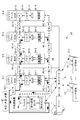
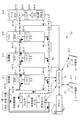
- FIG. 1 is a diagram showing a configuration of a water circulation management system S1 according to a first embodiment of the present invention.
- a water circulation management system S1 includes a server 1, user terminals 2-1 to 2-n (n is an arbitrary integer value of 1 or more), a water treatment device 3, and treated water
- the sensors 4C-1 to 4C-4, the drainage sensors 4D-1 to 4D-4, and the shower booths 5-1 to 5-4 are included.
- Server 1, user terminals 2-1 to 2n, water treatment device 3, treated water sensors 4C-1 to 4C-4, drainage sensors 4D-1 to 4D-4, shower booths 5-1 to 5 -4 are mutually connected via a network N such as the Internet.
- the water circulation management system S1 shown in FIG. 1 has a configuration in which a plurality of shower booths 5-1 to 5-4 are connected in series, in parallel, or in combination of series and parallel to the water treatment apparatus 3 by piping through the water channel WL.
- a solid line indicates a channel through which treated water flows
- a broken line indicates a channel through which drainage flows.
- the server 1 is based on sensing data obtained by sensing each of the processed water sensors 4C-1 to 4C-4 attached to the water channel WL or a valve 52 described later and the drainage sensors 4D-1 to 4D-4. To detect the use status of each of the shower booths 5-1 to 5-4.
- each of the user terminals 2-1 to 2-n and the users U1 to Un are collectively called “user terminal 2" and "user U”.
- each of the treated water sensors 4C-1 to 4C-4 individually these are collectively referred to as “each of the treated water sensors 4C”.
- drainage sensor 4D when it is not necessary to distinguish each of the drainage sensors 4D-1 to 4D-4 individually, these are collectively referred to as “shower booth 5”.
- shower booth 5 when it is not necessary to distinguish each of the shower booths 5-1 to 5-4, these are collectively referred to as “shower booth 5”.
- each element which comprises water circulation management system S1 is demonstrated.
- the server 1 controls the input of the treated water to each of the one or more use means based on sensing data obtained by the sensing of the sensing means. Specifically, the server 1 uses the shower booths 5-1 to 5 based on sensing data obtained by sensing the treated water sensors 4C-1 to 4C-4 and the drainage sensors 4D-1 to 4D-4. Control the input of treated water to each of -4. Thereby, it is possible to provide a water circulation management system capable of efficiently sharing a plurality of water using devices including a shower booth.
- the server 1 is based on the sensing data, the use start and stop of use of the treated water in one or more means of use, the usage amount, the usage time, the usage environment, various information related to the treated water, and drainage drainage.
- Information (hereinafter referred to as "water use information") including at least one of various information on drainage such as start, drainage stop, drainage volume, water pollution degree, etc. is generated.
- the server 1 generates water use information in the shower booths 5-1 to 5-4 based on the sensing data. Thus, it is possible to obtain water use information for efficiently sharing a plurality of water use devices including the shower booth.
- the server 1 can use the usage condition of the user who uses each of the one or more usage devices and the user who tries to use each of the one or more usage devices.
- Information (hereinafter referred to as "user usage information") including at least one of the time until is generated.
- the server 1 uses the usage status of the user U who uses each of the shower booths 5-1 to 5-4 and the shower booths 5-1 to 5-4.
- the user usage information including at least one of the time taken for the user U to use the shower booth 5 to become available is generated.
- the user usage information generated by the server 1 is displayed on the user terminal 2 or a touch panel 54 attached to the outer wall of the shower booth 5 described later.
- the user U who is going to use the shower booth 5 can immediately grasp the situation until the shower booth 5 becomes available. As a result, the convenience of the user U can be improved.
- the specific content of the function with which the server 1 is provided is later mentioned with reference to FIG.
- the user terminal 2 is an information processing apparatus operated by a user U who intends to use the shower booth 5, and is configured of, for example, a personal computer, a smartphone, a tablet, or the like.
- the water treatment apparatus 3 uses the one or more purification means to treat the waste water output from the one or more use means, and generates reusable treated water with the one or more use means. Specifically, the water treatment apparatus 3 uses the filters 31-1 to 31-m (m is an arbitrary integer value of 1 or more) to output the drainage water from the shower booths 5-1 to 5-4. The treatment is performed to generate reusable treated water in the shower booths 5-1 to 5-4.
- the filter 31 may be a strainer, a thread wound type filter, a sediment filter, an Ultra Filtration Membrane type filter (hereinafter referred to as “UF filter”), a microfiltration filter, or a Reverse Osmosis Membrane type.
- RO filter Forward osmosis filter
- ion exchange filter biological treatment
- activated carbon filter nano filter (NF)
- sand filtration ceramic filter
- centrifugal filter etc.
- the drainage treatment tank 32 is configured to include an intermediate tank and a concentration tank.
- the intermediate tank temporarily stores water that has passed through some of the filters 31 for purification. Concentrated water generated by purification is temporarily stored in a concentration tank and discarded when maintenance is performed. As described above, by providing the intermediate tank and purifying the water, the consumption of the filter 31 is reduced, and the life of the filter 31 can be extended. Also, by temporarily storing water in the intermediate tank, it is possible to estimate total organic carbon (TOC) and total nitrogen (TN) of the water. This can reduce the cost of water analysis.
- the water storage tank 33 is a tank for storing the generated treated water. The treated water stored in the water storage tank 33 is output to the shower booth 5. Also, the generated treated water is thermostated by a heater (not shown).
- the treated water sensor 4C senses the treated water input to each of the one or more use means. Specifically, the treated water sensor 4C senses the treated water input to each of the shower booths 5-1 to 5-4.
- the drainage sensor 4D senses the drainage output from each of the one or more use means. Specifically, the drainage sensor 4D senses the drainage output from each of the shower booths 5-1 to 5-4.
- the treated water sensor 4C and the drainage sensor 4D are water pressure, flow rate, pH, viscosity, turbidity, chromaticity, odor, total organic carbon, total inorganic carbon, total carbon, nitrate nitrogen, nitrite nitrogen, ammonia nitrogen And at least one sensor capable of detecting total nitrogen, residual chlorine, dissolved oxygen, total phosphorus, conductivity, and temperature.
- the shower booth 5 is a booth equipped with a shower used by the user U, and includes a pump 51, a valve 52, a shower head 53, a touch panel 54, and a drainage pan (not shown).
- the shower booth 5 can set usage conditions for men, women, children, pets, and the like according to the type of the user U to be used.
- the pump 51 inputs at least a part of the generated treated water to the shower head 53 via the valve 52.
- the pump 51 pumps at least a part of the generated treated water to the pump 51 provided in another shower booth 5.
- the pump 51-1 inputs at least a part of the treated water generated by the water treatment device 3 to the shower head 53-1 via the valve 52-1. Do.
- the pump 51-1 pumps out at least a part of the treated water generated by the water treatment device 3 to the pump 51-2 provided in the shower booth 5-2.
- the pumps 51-1 to 51-4 are composed of pumps such as a positive displacement pump, a non-positive displacement pump, a water pump, a bubble pump, an injection pump, and a submersible pump.
- the valve 52 is a valve for the user U who uses the shower booth 5 to operate to adjust the pressure of the treated water sprayed from the shower head 53.
- the shower head 53 is a shower head for sprinkling treated water input by the pump 51.
- the touch panel 54 is a touch panel attached to the outer wall of the shower booth 5 and displays water use information and user use information. Further, the touch panel 54 receives an input operation of the user U who intends to use the shower booth 5.
- FIG. 2 is a figure which shows the output adjustment function which adjusts the quantity of the treated water output from the water treatment apparatus 3. As shown in FIG. Specifically, FIG. 2 shows the relationship between the shower booth 5 and the output of the water treatment device 3 when two of the shower booths 5-1 to 5-4 are in operation.
- the server 1 adjusts the amount of treated water output from the water treatment apparatus 3 based on the water use information generated from the sensing data. For example, when some of the shower booths 5-1 to 5-4 are at rest, the server 1 is outputted from the water treatment apparatus 3 according to the number of the shower booths 5 being operated. Control the amount of treated water. Thereby, consumption of the electric power of the water treatment apparatus 3 can be suppressed. Moreover, it can suppress that processed water is output more than necessary. Specifically, for example, in the example shown in FIG. 2, two of the shower booths 5-1 to 5-4 are at rest. Therefore, the server 1 operates the amount of treated water output from the water treatment apparatus 3 based on the water use information generated from the sensing data, and all the shower booths 5-1 to 5-4 are operating.
- the server can operate when all the shower booths 5-1 to 5-4 are in operation. 1 doubles the amount of treated water output from the water treatment apparatus 3. This can prevent the occurrence of an event such as insufficient water pressure in the shower.
- the server 1 adjusts the amount of treated water output from the water treatment apparatus 3 based on the water use information generated from the sensing data, a plurality of shower booths 5 are operated. Even if the water pressure of the shower is constant, the comfort of the user U can be improved.
- FIG. 3 is a block diagram showing an example of the hardware configuration of the server 1 in the water circulation management system of FIG.
- the server 1 includes a central processing unit (CPU) 11, a read only memory (ROM) 12, a random access memory (RAM) 13, a bus 14, an input / output interface 15, an output unit 16, and an input unit 17. , Storage unit 18, communication unit 19, and drive 20.
- CPU central processing unit
- ROM read only memory
- RAM random access memory
- the CPU 11 executes various processes in accordance with a program stored in the ROM 12 or a program loaded from the storage unit 18 into the RAM 13. Data and the like necessary for the CPU 11 to execute various processes are also stored in the RAM 13 as appropriate.
- the CPU 11, the ROM 12 and the RAM 13 are connected to one another via a bus 14.
- An input / output interface 15 is also connected to the bus 14.
- An output unit 16, an input unit 17, a storage unit 18, a communication unit 19 and a drive 20 are connected to the input / output interface 15.
- the output unit 16 is configured of a display such as liquid crystal and displays various images.
- the input unit 17 is configured by various hardware buttons and the like, and inputs various information in accordance with an instruction operation of the operator.
- the storage unit 18 is configured by a DRAM (Dynamic Random Access Memory) or the like, and stores various data.
- the communication unit 19 controls communication performed with other devices (for example, the user terminal 2, the water treatment device 3, the treated water sensor 4C, the drainage sensor 4D, and the shower booth 5) via the network N including the Internet. Do.
- the drive 20 is provided as needed.
- a removable medium 30 made of a magnetic disk, an optical disk, a magneto-optical disk, a semiconductor memory or the like is appropriately attached to the drive 20.
- the program read from the removable media 30 by the drive 20 is installed in the storage unit 18 as necessary.
- the removable media 30 can also store various data stored in the storage unit 18 in the same manner as the storage unit 18.
- the user terminal 2 of the water treatment device 3 also have the hardware configuration shown in FIG. doing.
- the user terminal 2 and the shower booth 5 have a touch panel as the output unit 16 and the input unit 17.
- FIG. 4 is a functional block diagram showing an example of a functional configuration for realizing the water circulation process and the filter determination process among the functional configurations of the server 1 of FIG. 3.
- Water circulation treatment refers to water between one or more water use devices that use water to drain water and one or more water treatment devices that use the water use device to purify water and produce usable water.
- Process for managing the flow of The “filter determination process” is a process of determining the configuration of one or more filters 31 used for treatment of drainage by the water treatment apparatus 3 among the one or more filters 31 included in the water treatment apparatus 3.
- the acquisition unit 101, the information generation unit 102, and the input control unit 103 function.
- the determination unit 104 further functions.
- a sensing DB 401, a water use DB 402, and a user use DB 403 are provided.
- the acquisition unit 101 acquires sensing data obtained by sensing. Specifically, the acquisition unit 101 acquires sensing data obtained by the sensing of the processed sensor 4C and the drainage sensor 4D. The acquired sensing data is stored in the sensing DB 401 and managed.
- the information generation unit 102 generates water use information including at least one of use start, use stop, use amount, and use time of the treated water in each of the one or more use means based on the sensing data. . Specifically, based on the sensing data, the information generation unit 102 causes at least one of the use start, the use stop, the use amount, and the use time of the treated water in each of the shower booths 5-1 to 5-4. Water use information including the The generated water use information is stored and managed in the water use DB 402.
- the information generation unit 102 can use the usage condition of the user who uses each of the one or more usage devices and the user who tries to use the one or more usage devices.
- the user usage information including at least one of the time until and the time until is generated.
- the information generation unit 102 uses the use status of the user U who uses each of the shower booths 5-1 to 5-4, and the user U who tries to use the shower booth 5 showers.
- User utilization information including at least one of the time until the booth 5 becomes available is generated.
- the generated user usage information is stored in the user usage DB 403 and managed.
- the input control unit 103 controls the input of the processed water to each of the one or more use means based on the sensing data obtained by the sensing. Specifically, the input control unit 103 controls the input of treated water to each of the shower booths 5-1 to 5-4 based on sensing data obtained by sensing.
- the input control unit 103 further controls the input of the processed water to each of the one or more use means based on the water use information. Specifically, the input control unit 103 controls the input of the treated water to each of the shower booths 5-1 to 5-4 based on the sensing data and the water use information generated based on the sensing data. .
- the determination unit 104 determines, based on the water use information, the configuration of the purification unit to be used for the treatment of the drainage among the one or more purification units. Specifically, the determination unit 104 determines, based on the water use information, the configuration of at least one of the filters 31-1 to 31-m to be used for the treatment of the drainage.
- the sensing DB 401 stores and manages sensing data obtained by sensing by the processed sensor 4C and the drainage sensor 4D.
- the water usage DB 402 stores and manages water usage information generated based on the sensing data.
- the user usage DB 404 stores and manages user usage information generated based on sensing data.
- FIG. 5 is a diagram showing a specific example of a screen displayed on the user terminal 2 of the user U who intends to use the shower booth 5.
- the server 1 generates user usage information based on the sensing data and causes the user terminal 2 to display this.
- the shower IDs of 1 to 4 are respectively used as information for uniquely identifying each of the shower booths 5-1 to 5-4. It has been granted.
- a waiting time for each shower ID is displayed on the user terminal 2 as user use information.
- the waiting time of the shower booth 5-1 with the shower ID "01” is “5 min (minutes)”
- the waiting time of the shower booth 5-2 with the shower ID “02” is “15 min. (Minutes)
- waiting time of shower booth 5-3 with shower ID “03” is “1 min (minutes)”
- waiting of shower booth 5-4 with shower ID “04” It is displayed on the user terminal 2 that the time is "OK (that is, immediate available)”.
- the user U can immediately know that the shower booth 5-4 with the shower ID "04" can be used immediately.
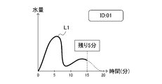
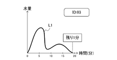
- FIG. 6 is a graph used to estimate the waiting time of the shower booth 5.
- the horizontal axis of the graph of FIG. 6 has shown time (minute), and the vertical axis has shown the amount of water.
- FIG. 6A is a graph used to estimate the waiting time of the shower booth 5-1 with the shower ID “01”. As shown in FIG. 6A, the waiting time of the shower booth 5-1 with the shower ID “01” is estimated to be “the remaining 5 minutes”.
- FIG. 6B is a graph used when estimating the waiting time of the shower booth 5-2 whose shower ID is “02”. As shown in FIG. 6B, the waiting time of the shower booth 5-2 with the shower ID “02” is estimated to be “remaining 15 minutes”.
- FIG. 6C is a graph used to estimate the waiting time of the shower booth 5-3 with the shower ID “03”. As shown in FIG. 6C, the waiting time of the shower booth 5-3 with the shower ID “03” is estimated to be “the remaining one minute”.
- FIG. 7 is a view showing a specific example of the operation screen displayed on the user terminal 2 of the user U who intends to use the shower booth 5.
- FIG. 6 the situation of each of the shower booths 5-1 to 5-4 is shown in FIG. Is displayed.
- FIG. 7 the information classified by the tab is displayed for each situation of the shower booths 5-1 to 5-4. Specifically, “in use”, “available”, and “in maintenance (during maintenance)” are illustrated as the respective statuses of the shower booths 5-1 to 5-4. Then, it is shown that the shower booth 5-4 whose shower ID is "04" is "available". Thereby, the user U can immediately know that the shower booth 5-4 with the shower ID “04” can be used immediately, and the convenience of the user U can be improved.
- FIG. 8 is a view showing a specific example of the operation screen displayed on the user terminal 2 of the user U who intends to use the shower booth 5.
- buttons indicating the shower booths 5-1 to 5-4 are arranged. Specifically, a button displayed as “shower booth (ID: 01)", a button displayed as “shower booth (ID: 02)", and “shower booth (ID: 03)” were displayed. A button and a button displayed as “shower booth (ID: 04)” are arranged. For example, when the user U wants to know the status of the shower booth 5-4, the user U presses a button displayed as "shower booth (ID: 04)” indicating the shower booth 5-4.
- FIG. 9 is a view showing a specific example of the operation screen displayed on the user terminal 2 of the user U who intends to use the shower booth 5.
- the user U operates the user terminal 2 to select any one of the shower booths 5-1 to 5-4 and prepares the shower booth 5 to be available (hereinafter referred to as “use Can be instructed to start).
- FIG. 9A is a view showing a specific example of the screen displayed on the user terminal 2 when the preparation for using the shower booth 5 is started. Specifically, "30:00 (30 minutes)" is displayed in the display area F11 as the remaining time until the preparation for use is completed, together with the message "the preparation for use is started".
- the preparation for using the shower booth 5 includes preparation of treated water used for the shower by purifying the drainage, preparation for setting the water temperature to the target temperature, and the like.
- FIG. 9B is a diagram showing a specific example of the screen displayed on the user terminal 2 when the preparation for using the shower booth 5 is completed. Specifically, "00:00 (0 minutes)" is displayed in the display area F11 as the remaining time until the preparation for use is completed, together with the message "the screen is switched to the user screen”.
- FIG. 9C is a view showing a specific example of the user screen displayed when the shower booth 5 is available among the screens displayed on the user terminal 2.
- the user screen shown in FIG. 9C is configured to include display areas F21 to F23. Specifically, in the display area F21, the quality (clean) of the treated water prepared for the shower is displayed. Further, in the display area F22, the available time (15 minutes) of the shower booth 5 is displayed. Further, in the display area F23, the amount (40 L (liter)) of processed water prepared for the shower is displayed. Thereby, the user U confirms the quality of treated water, the available time of the shower booth 5, and the amount of treated water that can be used along with the use of the shower booth 5 before starting the use of the shower booth 5. be able to.
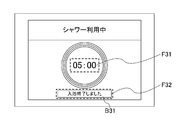
- FIG. 10 is a diagram showing a specific example of the operation screen displayed on the user terminal 2 of the user U while using the shower booth 5 or after using the shower booth 5.
- FIG. 10A is a diagram showing a specific example of the operation screen displayed on the user terminal 2 of the user U while using the shower booth 5.
- the screen shown in FIG. 10A described above is configured to include a display area F31 and a display area F32.
- the display area F31 it is displayed that the time elapsed since the user U started using the shower booth 5 is 05:00 (five minutes).
- a button B ⁇ b> 31 pressed by the user U when ending the use of the shower booth 5 is displayed.
- FIG. 10B is a diagram showing a specific example of the operation screen displayed on the user terminal 2 of the user U after using the shower booth 5.
- the user terminal 2 of user U who uses shower booth 5 uses the result of using shower booth 5 (hereinafter referred to as “bathing result”).
- the screen shown in FIG. 10B is configured to include a display area F41 and a display area F42.
- display area F41 the usage time (bathing time) of shower booth 5 was 10:00 (10 minutes), and the amount of treated water used with usage of shower booth 5 was 25 liters (liter). It is displayed that it was.
- a button B41 is displayed which is depressed when the user U confirms the bathing result displayed in the display area F41.
- the user terminal 2 displays an operation screen (FIG.
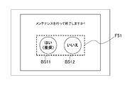
- FIG. 11 is a diagram showing a specific example of an operation screen for performing an operation of ending the use of the shower booth 5.
- FIG. 11A is a diagram showing an example of an operation screen for issuing an instruction to end use of the shower booth 5 after maintenance of the shower booth 5 is performed. Specifically, the message “Do you want to finish maintenance?" Is displayed, and button B 511 with “Yes (recommended)" and “No” are displayed in display area F51. The button B512 is displayed. The user U presses one of the two buttons displayed in the display area F51.
- buttons displayed in the display area F51 of FIG. 11A when the button B512 described as “No” is pressed, the use of the shower booth 5 can be ended as it is. On the other hand, when the button B 511 described as “Yes (recommended)” is pressed, an operation screen for maintenance of the shower booth 5 is displayed.
- FIG. 11B is a diagram showing an example of an operation screen for performing maintenance on the shower booth 5.
- maintenance work of the shower booth 5 is shown to be performed in the following three steps. That is, as a first step, a message of "Please drain the concentrated water” is displayed as a guide to the effect of draining the concentrated water.
- a message "Please perform flushing” is displayed as a guide for performing the flushing.
- a message “Please remove drainage tank and implement drainage” is displayed as a guide for performing the work of discarding the drainage accumulated in the drainage tank of the shower booth 5.
- buttons described as “Done”, which are pressed when the maintenance work in each step is performed are respectively displayed.
- FIG. 12 is a diagram showing a specific example of the maintenance screen displayed on the user terminal 2.
- pump information information on the state of the pump 51
- valve information Information on the state of the valve 52
- filter information information on the state of the filter 31
- a maintenance screen configured of water use information, pump information, valve information, and filter information is displayed on the user terminal 2.
- the maintenance screen is configured to include display areas F71 to F74.
- the display area F71 contents of sensing data obtained by sensing of the treated water sensor 4C and the drainage sensor 4D are displayed together with a title described as "sensor value (check time-series data)".
- the content of the sensing data to be displayed is not particularly limited, but in the example shown in FIG. 11, an ID number (SP ID) uniquely identifying the corresponding pump 51 and various water quality data (A to D) Is displayed.
- icons indicating the three pumps 51 displayed as “A”, “B”, and “C” are displayed as specific examples of the pump information, and among these, "A" is displayed. Only the colored icons are colored. This means that the pump 51 indicated by the icon displayed as "A” is operating.
- valve information icons indicating the three valves 52 displayed as “A”, “B”, and “C” are displayed, and among them, "A" is displayed
- the selected icon and the icon displayed as “B” are colored. This means that the pump 51 indicated by the icon indicated by “A” and the pump 51 indicated by the icon indicated by “B” are operating.
- the filter 31 is a sediment filter, a pre-activated carbon type filter (hereinafter referred to as “pre-activated carbon filter”), two RO filters (RO1 filter and RO2 filter), and a post activated carbon type
- pre-activated carbon filter a pre-activated carbon type filter
- RO1 filter and RO2 filter two RO filters
- post activated carbon filter a filter
- UF membrane filter a filter
- the state of the sediment filter, the front activated carbon filter, the RO1 filter, the RO2 filter, the rear activated carbon filter, and the UF filter, which constitute the filter 31, are displayed in a form that can be grasped at first glance. Specifically, when the life from the replacement of the filter 31 to the next replacement is indicated in five steps, the length of the life until the next replacement is indicated by the number of blocks. For example, the lifetime of the sediment filter of the filter 31 is about 3/5 of the remaining. On the other hand, the filter 31 specified by the name “RO1” has no remaining life, and a mark prompting replacement is displayed.
- FIG. 13 is a diagram showing a specific example in the case where the details of the sensor data are displayed from the maintenance screen displayed on the user terminal 2.
- the processed water (INPUT WATER) W1 input from the water treatment apparatus 3 to the shower booth 5 and the processed water sprayed from the shower head 53 of the INPUT WATER (SERVICE as the details of the sensor data)
- the graph which shows transition of each water quality data with the water (OUTPUT WATER) W3 output from WATER) W2 and the shower booth 5 is shown.
- the horizontal axis of the graph shown in FIG. 12 represents time (minutes), and the vertical axis represents the degree of water purification.
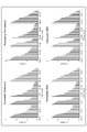
- FIG. 14 is a diagram showing a specific example in the case where the details of the filter information are displayed from the maintenance screen displayed on the user terminal 2.
- the transition of the permeability of each of the sediment filter (Sediment), the front activated carbon filter (Pre-Carbon), the RO membrane filter (RO), and the UF membrane filter (FU) Is displayed on the user terminal 2.
- the horizontal axis of the graph shown in FIG. 14 indicates time (month), and the vertical axis indicates the filter capability (k-value).
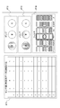
- FIG. 15 is a view showing the configuration of the filter of the filter 31 as the purification means used for the treatment of waste water.
- the server 1 determines the configuration of at least one of the filters 31-1 to 31-m to be used for the treatment of drainage based on the water use information.
- the configuration of the one or more filters 31 for purifying the waste water can be efficiently determined according to the amount of waste water, the type of substance contained in the waste water, and the like.
- the drainage can be efficiently purified, it is possible to delay the replacement time of the filter 31 and extend the life of the filter 31.
- FIGS. 15A and 15B specific examples of the configuration of one or more filters 31 used for treating wastewater are shown, respectively.
- two types of filters (filter A and filter B) are prepared in the filter 31 respectively.
- the configuration of the one or more filters 31 for purifying the waste water is determined according to the amount of the waste water, the type of the substance contained in the waste water, and the like. For example, when the user U who uses the shower booth 5 is a male and a female, when the woman U may drop makeup, a difference occurs in substances contained in the drainage.
- the shower booth 5 whose shower ID is "M01" is shown by FIG. 15A as an example of the shower booth 5 for men.
- the filter 31 is configured to use two types of filters (filter A and filter B) one by one. Specifically, of the filter A1, the filter A2, the filter B1 and the filter B2 prepared as the filter 31, the water channel WL passes through the filter A2 and the filter B1.
- FIG. 15B shows a shower booth 5 with a shower ID “F01” as an example of the shower booth 5 for women.
- the filter 31 is configured to use all the filters. Specifically, the water channel WL passes through all of the filter A1, the filter A2, the filter B1 and the filter B2 prepared as the filter 31.
- drainage can be efficiently purified by changing the configuration of the filter 31 used in the shower booth 5 for men and the shower booth 5 for women. As a result, it is possible to delay the replacement time of the filter 31 and extend the life of the filter 31.
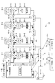
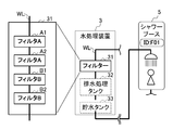
- FIG. 16 is a view showing a part of the configuration of a water circulation management system S2 according to a second embodiment of the present invention.
- the water circulation management system S2 is different from the first embodiment, and the water storage tank 33 is provided independently of the water treatment apparatus 3. Specifically, four water storage tanks 33-1 to 33-4 are independently provided from the three water treatment devices 3-1 to 3-3.
- the water circulation management system S2 is, like the water circulation management system S1 shown in FIG. 1, treated water sensors 4C-1 to 4C-4, drainage sensors 4D-1 to 4D-4, and a shower booth. It is configured to include 5-1 to 5-4.
- the water circulation management system S2 shown in FIG. 16 has a configuration in which a plurality of shower booths 5-1 to 5-4 are connected by piping in series, in parallel, or in combination of series and parallel to a plurality of water treatment devices 3-1 to 3-3. It has become.
- the server 1 has a shower booth 5-5 based on the results of sensing by the treated water sensors 4C-1 to 4C-4 attached to the water channel WL or the valve 52 and the drainage sensors 4D-1 to 4D-4, respectively. The use condition of each of 1 to 5-4 is detected. As shown in FIG.
- the water circulation management system S2 includes a plurality of water treatment devices 3-1 to 3-3 and a plurality of water storage tanks 33-1 to 33-4 independent of the water treatment device 3, A large amount of treated water can be prepared and a large amount of waste water can be treated. As a result, even if the shower booths 5-1 to 5-4 as well as more shower booths 5 are included in the water circulation management system S2, stable supply of treated water can be realized. As a result, the shower booth 5 can be installed at a place where the use of the shower booth 5 is expected by a large number of people, such as a campsite, an event site, an evacuation site when a disaster occurs, a trailer house, a beach.
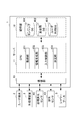
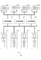
- FIG. 17 is a diagram showing a configuration of a water circulation management system S3 according to a third embodiment of the present invention.
- the method of controlling a plurality of shower booths has been described as an example of the water treatment apparatus.
- the water treatment apparatus as a means of use in the present invention is not limited to a shower booth, and is a concept encompassing any apparatus having a function of draining using water.
- the water circulation management system S3 according to the third embodiment of the present invention is different from the above-described first and second embodiments, and includes four water treatment devices as the use means in the present invention. Specifically, as each of the four water treatment devices, a dishwasher / dryer (hereinafter, "dishwasher") 5-1, a washing machine 5-2, a toilet 5-3, and a shower booth 5-4 And each one is included.
- the server 1 is based on the results of sensing by the treated water sensors 4C-1 to 4C-4 attached to the water channel WL or the valves 52-1 to 52-4 and the drainage sensors 4D-1 to 4D-4, respectively.
- the use condition of the dishwasher 5-1, the washing machine 5-2, the toilet 5-3, and the shower booth 5-4 is detected. Then, the server 1 controls the input of the processed water to each of the dishwasher 5-1, the washing machine 5-2, the toilet 5-3, and the shower booth 5-4.
- the processed sensor 4C is attached to, for example, the following place to perform sensing. That is, in the water treatment apparatus 3, the treated sensor 4C (not shown) attached to the inside of the waste water treatment tank 32 and the water storage tank 33 and the inflow part of the treated water is the amount, temperature, Sense flow rate and pressure.
- the treated sensor 4C-1 attached to the faucet, the inflow portion of the treated water, and the piping connected to the sink of the kitchen senses the flow rate and pressure of the treated water .
- the treated sensor 4C-2 attached to the inflow part of treated water and the pipe connected to the washing machine 5-2 senses the flow rate and pressure of the treated water.
- the processed sensor 4C-3 attached to the inflow portion of the processed water, the toilet tank, and the portion where the toilet flush water flows out from the toilet tank is the amount and flow rate of the processed water, Sense pressure and temperature.
- the processed sensor 4C-4 attached to the valve 52-4, the shower head 53-4, and the connecting pipe of the shower senses the flow rate, pressure, and temperature of the processed water. .
- the drainage sensor 4D is attached to, for example, the following place to perform sensing. That is, in the water treatment apparatus 3, the drainage sensor 4D (not shown) attached to the inside of the drainage processing tank 32 and the water storage tank 33 and the drainage outlet part measures the water amount, temperature, flow rate and pressure of drainage. To sense. In the dishwasher 5-1, the drainage sensor 4D-1 attached to the drainage port of the kitchen sink, the outlet of treated water, and the piping connected to the drainage port of the kitchen sink, the flow rate of drainage , Pressure, electrical conductivity, temperature, viscosity, pH, water quality etc.
- the drainage sensor 4D-2 attached to the drainage hose for washing machine, the drainage port, and the piping connected to the drainage port, the flow rate, pressure, electric conductivity, and temperature of drainage To sense.
- the drainage sensor 4D-4 attached to the drainage port and the piping connected to the drainage port senses the flow rate of drainage, pressure, electric conductivity, temperature, pH, water quality and the like.
- the drainage sensor 4D-4 attached to the drainage port and the piping connected to the drainage port senses the flow rate, pressure, temperature, pH, electric conductivity, and water quality of the drainage.
- a water circulation management system capable of efficiently sharing a plurality of water using devices (a dishwasher, a washing machine, a toilet, and a shower booth) including a shower booth.
- the following sharing is possible. That is, when the water circulation management system is shared by the dishwasher 5-1 and the shower booth 5-4, the flow rate, pressure and temperature of the treated water used in the shower booth 5-4 are sensed. , Sensing the flow rate, pressure and temperature of treated water used in the dishwasher 5-1. Furthermore, the amount, flow rate, pressure, and temperature of the treated water stored in the water storage tank 33 of the water treatment device 3 are sensed, and the temperature, flow rate, and pressure that are optimal for the user U use And 51-4 and a heater (not shown).
- the filter 31 to be used is switched according to the water quality (for example, the amount of pollution).
- the excess storage tank amount is measured by a water amount sensor, and the amount of water used is distributed.
- the following sharing is possible. That is, when the water circulation management system is shared by the dishwasher 5-1, the washing machine 5-2, the toilet 5-3, and the shower booth 5-4, the dishwasher 5-1 is used. By sensing the flow rate, pressure, and temperature of treated water, the usage status of the dishwasher 5-1 is sensed. Also, by sensing the flow rate, pressure, and temperature of the treated water used in the washing machine 5-2, the usage status of the washing machine 5-2 is sensed. In addition, by sensing the flow rate, pressure, and temperature of treated water used for the toilet 5-3, the usage status of the toilet 5-3 is sensed. Further, the sensing condition of the shower booth 5-4 is sensed by sensing the flow rate, pressure and temperature of the treated water used for the shower booth 5-4.
- the temperature, flow rate, and pressure that are optimal for use by the user U are fed back to the pumps 51-1 and 51-4 and the heater (not shown).
- the filter 31 to be used is switched according to the water quality (for example, the amount of pollution).
- the excess storage tank amount is measured by a water amount sensor, and the amount of water used is distributed.
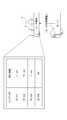
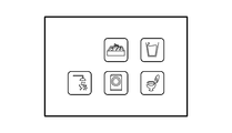
- FIG. 18 shows a screen displayed in real time on the user terminal 2 and showing the status of the dishwasher 5-1 as a water using device, the washing machine 5-2, the toilet 5-3, and the shower booth 5-4. It is a figure which shows an example. As shown in FIG. 18, the user terminal 2 displays icons indicating the dishwasher 5-1 as a water using device, the washing machine 5-2, the toilet 5-3, and the shower booth 5-4. ing.
- the screen shown in FIG. 18A is a screen showing a state in which the user U can use (hereinafter referred to as “available state”). That is, in the state shown in FIG. 18A, the use by the user U has not yet been started regarding the dishwasher 5-1, the washing machine 5-2, the toilet 5-3, and the shower booth 5-4 as the water using device It shows the state.
- the screen shown in FIG. 18B is a screen showing a state in which the user U is in use. That is, as shown in FIG. 18B, the colors of the two icons are different from the colors of the icons shown in FIG. 18A. This shows that the user U starts using the washing machine 5-2 and the shower booth 5-4.
- the screen shown to FIG. 18C is a screen which shows the state in process of water treatment. As shown in FIG. 18C, the remaining time until becoming available is displayed on the two icons. Specifically, the icon arranged at the lower left indicates that the remaining eight minutes are until the shower booth 5-4 becomes available. In addition, the color of the icon arranged below the center is different from the screen shown in FIG. 18A. This is shown to be "3 minutes" until the washing machine 5-2 becomes available.
- FIG. 19 is a diagram showing a configuration of a water circulation management system S4 according to a fourth embodiment of the present invention.
- the water circulation management system S4 is configured to include a plurality of water treatment devices 3, unlike the above-described third embodiment.
- the configuration of the water circulation management system S4 shown in FIG. 17 further includes two water treatment devices 3-2 and 3-3, and as a result, the number of water use devices (four And the number of water treatment devices 3 (four units) are in a one-to-one relationship.
- the treated water can be prepared individually for each of the water using devices 5-1 to 5-4, and a large amount of drainage can be treated.
- the shower booth 5 can be installed at a place where use of the shower booth 5 by a large number of people is expected, for example, an evacuation site, an event site, a beach or the like.
- the number of water use apparatuses such as shower booth 5
- the number of water use apparatuses is a structure of four units in total, this is only an illustration and can also be comprised by five or more.
- the water use device includes the dishwasher, the washing machine, the toilet, and the shower booth, but this is merely an example. Any device having the function of draining using water can be adopted as a water using device.
- the operation by the user U is for the user terminal 2, but is not limited thereto. It may be an operation on the touch panel 54 provided in the shower booth 5. That is, the screens shown in FIG. 5, FIG. 7, and FIG. 8 to FIG. 12 can also be displayed by activating the application program installed in the user terminal 2 or displaying them on the touch panel 54 provided in the shower booth 5. It can also be done.
- the configuration of the filter 31 determined by the determination unit 104 is different for the shower booth 5 for men and the shower booth 5 for women, but this is an example. Not too much. For example, by monitoring the drainage based on the water use information, the water quality of the drainage can be evaluated, and the configuration of the filter 31 and the water channel WL can be determined according to the degree of contamination of the drainage. Also, the life of the filter 31 can be predicted. Thereby, the load and environmental load which the filter 31 receives can be minimized.
- the configuration of the filter can also be determined. Specifically, for example, the configuration of a filter suitable for wastewater treatment can also be determined based on climate, geographical information, lifestyle, etc. obtained from water use information. In this way, for example, it is possible to determine the configuration of the filter corresponding to every scene, such as camping in a forest, an office, a running event in India, camping in a mountain, and the like. The configuration of the filter thus determined is accumulated in the water use DB 402 together with the result, so that the determination unit 104 can continue learning toward the future, and can determine a more suitable filter configuration. Become.
- a predetermined sensor is adopted as treated water sensor 4C and drainage sensor 4D, it is not limited to this. Based on the water use information, it may be possible for the server 1 side to propose which sensor among various sensors should be adopted.
- the water input to the use means such as a shower is output from the water treatment means that performs water treatment such as purification on the waste water output from the use means was. That is, in the above-mentioned embodiment, the circulation processing system of water was adopted. However, adopting a water recycling system is not particularly essential.
- the water input to the use means may be water outputted from the water treatment means, or from other than that It may be supplied water. In other words, the water output from the water treatment means may be used for the use means, or may be used for something other than the use means.
- the shower booths 5-1 to 5-4, the server 1, the user terminal 2, the water treatment apparatus 3, and the treated water sensor 4 are networks N such as the Internet. Although described as being mutually connected via, we will supplement this briefly. That is, specifically, for example, the shower booths 5-1 to 5-4 may communicate with each other using the Internet, short distance wireless communication, etc. 4 may directly communicate with the server 1 or the cloud without passing through the user terminal 2 or the like.
- the server 1 does not have to recognize in advance various devices related to the use means connected to itself. That is, the server 1 may automatically determine the connection status of various devices related to the use means from the result of sensing by the sensor 4C or the sensor 4D. As a result, the server 1 does not need to acquire the connection status of the various devices related to the use means in advance, and even if such information can not be acquired, the connection of the various devices related to the use means It is possible to execute processing based on the situation.
- connection status can be reflected in the display method of the icon shown in FIG. That is, for example, although not shown, icons A, B and C are displayed at the bottom of the icon, and only the device corresponding to C is connected, and A and B are not connected. Only the icon may be displayed bright, and the icons A and B may be displayed dark.
- the series of processes described above can be performed by hardware or software.
- the functional configuration of FIG. 4 is merely an example and is not particularly limited. That is, it is sufficient if the information processing system is provided with a function capable of executing the above-described series of processes as a whole, and what functional block is used to realize this function is not particularly limited to the example of FIG.
- the location of the functional block is not particularly limited to that in FIG. 4 and may be arbitrary.
- one functional block may be configured by hardware alone, may be configured by software alone, or may be configured by a combination of them.
- a program configuring the software is installed on a computer or the like from a network or a recording medium.
- the computer may be a computer incorporated in dedicated hardware.
- the computer may be a computer capable of executing various functions by installing various programs, such as a general-purpose smartphone or personal computer other than a server.
- a recording medium including such a program is not only configured by a removable medium (not shown) distributed separately from the apparatus main body to provide the program to the user, but is also incorporated in the apparatus main body in advance. And a recording medium provided to the user.
- the processing performed chronologically along the order is, of course, parallel or individually not necessarily necessarily chronologically processing. It also includes the processing to be performed.
- the term "system” is intended to mean an overall device composed of a plurality of devices, a plurality of means, and the like.
- the water circulation management system to which the present invention is applied may take various configurations as long as it has the following configuration. That is, the water treatment system (for example, the water circulation treatment system S1 of FIG. 1) to which the present invention is applied is When the input water is used by the user (e.g., user U in FIG. 1), one or more means of use (e.g., shower booths 5-1 to 5-4 in FIG.
- one or more water treatment means capable of performing predetermined water treatment on at least a part of the drainage output from the one or more use means; Based on the respective results of the one or more detection means, at least a part of each of the one or more use means and the one or more water treatment means is a control object, and predetermined control for the control object is performed.
- Control means for example, the input control unit 103 in FIG. 4) to be executed; Can be provided.
- the information generation means may Water use information may be generated that includes at least one of use start, use stop, use amount, and use time of water by the user in each of the one or more use means.
- Water use information may be generated that includes at least one of use start, use stop, use amount, and use time of water by the user in each of the one or more use means.
- control means further includes: Based on the generated water use information, as the predetermined control, the input of the treated water to each of the one or more use means can be controlled. Thereby, based on the generated water use information, it is possible to provide a water treatment system that can use drainage even in an environment where it is difficult to secure water.
- the information generation means may A user including at least one of a use situation of a user who uses each of the one or more use means, and a time until a user who tries to use the one or more use means can use the use means. Usage information can be generated. Accordingly, it is possible to provide a water treatment system that can use drainage even in an environment where it is difficult to secure water based on user usage information.
- the water treatment means comprises one or more purification means, It can further comprise determination means for determining the configuration of the purification means to be used for treatment of the drainage among the one or more purification means based on the water use information. Thereby, the filter 31 can be used efficiently.
- the means for using includes a shower
- the control means Based on the water use information, the pressure of the water sprayed from the shower can be controlled as the predetermined control.
- control means may further include, as the predetermined control, The temperature and amount of water sprayed from the shower can be controlled.
- the predetermined control The temperature and amount of water sprayed from the shower can be controlled.
- a pump for example, the pump 51 of FIG. 1
- operation of a shower head for example, the shower head 53 of FIG. 1
- opening and closing of a shower valve for example, valve 52 of FIG. 1
- At least one sensor for example, the treated water sensor 4C in FIG. 1, the drainage sensor 4D in FIG. 1 connected to the piping (for example, the water channel WL in FIG. 1) between the shower booths 5-1 to 5-4);
- a change in one or more electric signals obtained can be detected to notify the user U of the availability status of the shower booth and the time until the shower booth becomes available.
- the sensor head detects a change in one or more electric signals obtained from the operation of the shower head or one sensor connected to the piping between the shower booths, performs feedback, and makes the water pressure of the shower constant. be able to.
- the filter and the water channel can be switched according to the use conditions of the shower to provide an optimal water purification method.
- the water channel is switched or opened and closed according to the use condition of the shower, the operating condition of the device, and the water storage amount, and the surplus tank (for example, the water storage tank 33-1 to 33-4 in FIG. 16) or the water treatment device
Landscapes
- Engineering & Computer Science (AREA)
- Health & Medical Sciences (AREA)
- Public Health (AREA)
- Water Supply & Treatment (AREA)
- Hydrology & Water Resources (AREA)
- Life Sciences & Earth Sciences (AREA)
- Chemical & Material Sciences (AREA)
- Organic Chemistry (AREA)
- Environmental & Geological Engineering (AREA)
- General Health & Medical Sciences (AREA)
- Computer Networks & Wireless Communication (AREA)
- Physics & Mathematics (AREA)
- General Physics & Mathematics (AREA)
- Epidemiology (AREA)
- Business, Economics & Management (AREA)
- General Engineering & Computer Science (AREA)
- Automation & Control Theory (AREA)
- Economics (AREA)
- Human Resources & Organizations (AREA)
- Strategic Management (AREA)
- Entrepreneurship & Innovation (AREA)
- General Business, Economics & Management (AREA)
- Game Theory and Decision Science (AREA)
- Educational Administration (AREA)
- Marketing (AREA)
- Operations Research (AREA)
- Quality & Reliability (AREA)
- Tourism & Hospitality (AREA)
- Development Economics (AREA)
- Theoretical Computer Science (AREA)
- Bathtubs, Showers, And Their Attachments (AREA)
- Domestic Plumbing Installations (AREA)
- Management, Administration, Business Operations System, And Electronic Commerce (AREA)
- Sink And Installation For Waste Water (AREA)
- Selective Calling Equipment (AREA)
- Excavating Of Shafts Or Tunnels (AREA)
- Water Treatment By Electricity Or Magnetism (AREA)
- Electrical Discharge Machining, Electrochemical Machining, And Combined Machining (AREA)
Priority Applications (7)
| Application Number | Priority Date | Filing Date | Title |
|---|---|---|---|
| ES18858187T ES2951434T3 (es) | 2017-09-20 | 2018-09-20 | Sistema de tratamiento de agua |
| CN201880061108.8A CN111108518B (zh) | 2017-09-20 | 2018-09-20 | 水处理系统 |
| JP2019543709A JP6755063B2 (ja) | 2017-09-20 | 2018-09-20 | 水処理システム |
| PL18858187.0T PL3686818T3 (pl) | 2017-09-20 | 2018-09-20 | Układ do uzdatniania wody |
| CN202311025517.1A CN117049618B (zh) | 2017-09-20 | 2018-09-20 | 水处理系统 |
| EP18858187.0A EP3686818B1 (en) | 2017-09-20 | 2018-09-20 | Water treatment system |
| US16/648,954 US11713561B2 (en) | 2017-09-20 | 2018-09-20 | Water treatment system |
Applications Claiming Priority (2)
| Application Number | Priority Date | Filing Date | Title |
|---|---|---|---|
| JP2017-180580 | 2017-09-20 | ||
| JP2017180580 | 2017-09-20 |
Publications (1)
| Publication Number | Publication Date |
|---|---|
| WO2019059309A1 true WO2019059309A1 (ja) | 2019-03-28 |
Family
ID=65811331
Family Applications (1)
| Application Number | Title | Priority Date | Filing Date |
|---|---|---|---|
| PCT/JP2018/034909 Ceased WO2019059309A1 (ja) | 2017-09-20 | 2018-09-20 | 水処理システム |
Country Status (7)
| Country | Link |
|---|---|
| US (1) | US11713561B2 (https=) |
| EP (1) | EP3686818B1 (https=) |
| JP (3) | JP6755063B2 (https=) |
| CN (2) | CN117049618B (https=) |
| ES (1) | ES2951434T3 (https=) |
| PL (1) | PL3686818T3 (https=) |
| WO (1) | WO2019059309A1 (https=) |
Cited By (4)
| Publication number | Priority date | Publication date | Assignee | Title |
|---|---|---|---|---|
| WO2021095821A1 (ja) * | 2019-11-14 | 2021-05-20 | Wota株式会社 | 情報処理装置、方法、プログラム、システム |
| JP2021079305A (ja) * | 2019-11-14 | 2021-05-27 | Wota株式会社 | 水処理装置、水処理システム、水処理方法、コンピュータ装置 |
| JP7092426B1 (ja) | 2022-04-19 | 2022-06-28 | Wota株式会社 | 水成分推定装置、水成分推定方法、及び水成分推定プログラム |
| EP4019471A4 (en) * | 2019-08-23 | 2022-12-28 | Wota Corp. | WATER TREATMENT SYSTEM AND WATER TREATMENT PROCESS |
Families Citing this family (10)
| Publication number | Priority date | Publication date | Assignee | Title |
|---|---|---|---|---|
| JP7289107B2 (ja) * | 2019-03-11 | 2023-06-09 | パナソニックIpマネジメント株式会社 | Usbコンセント |
| WO2022032787A1 (zh) * | 2020-08-13 | 2022-02-17 | 中国建筑设计研究院有限公司 | 公共建筑室内灰水净化回用装置、系统及方法 |
| CN116490470A (zh) * | 2020-11-25 | 2023-07-25 | 宝洁公司 | 用于水再使用的系统和方法 |
| EP4271892A4 (en) * | 2021-01-04 | 2024-12-04 | Orbital Systems AB | WATER DISTRIBUTION SYSTEM |
| KR102273732B1 (ko) * | 2021-03-03 | 2021-07-07 | 대한민국 (관리부서 : 환경부 국립환경과학원장) | 미계측 영업지 일일 물사용량 산출 시스템 |
| US12017940B2 (en) * | 2021-03-22 | 2024-06-25 | Ruth Weaver | Bath water recycling system |
| CN116940737A (zh) | 2021-03-31 | 2023-10-24 | 宝洁公司 | 用于使用点水修改的系统和方法 |
| NO348547B1 (no) * | 2022-11-07 | 2025-03-03 | Kronborg Solutions As | Utslippsfritt vannsirkulasjonssystem for bruksenhet |
| CN115572020B (zh) * | 2022-11-09 | 2023-03-07 | 自然资源部第二海洋研究所 | 一种污水处理中溶解无机碳自动监测装置 |
| WO2025019439A2 (en) * | 2023-07-14 | 2025-01-23 | Milligan Christopher B | A residential water quality monitoring system and methods of use thereof |
Citations (6)
| Publication number | Priority date | Publication date | Assignee | Title |
|---|---|---|---|---|
| JPH1110177A (ja) * | 1997-06-19 | 1999-01-19 | Inax Corp | 浴室排水のオゾン水による浄化再利用装置 |
| JP2001191866A (ja) | 1999-11-25 | 2001-07-17 | Eads Airbus Gmbh | シャワー設備 |
| US20140053909A1 (en) * | 2011-05-03 | 2014-02-27 | Nigel Charles Savage | Water Recirculation System |
| JP2015107464A (ja) * | 2013-12-05 | 2015-06-11 | 三菱重工業株式会社 | 循環水利用システム |
| JP2017021713A (ja) * | 2015-07-14 | 2017-01-26 | 日立マクセル株式会社 | 情報提供システム |
| US20170226720A1 (en) * | 2014-11-14 | 2017-08-10 | Orbital Systems Ab | Apparatus and handheld shower unit thereof for water supply and sanitary purposes, e.g. for allowing purification and either recycling of water or discarding of water |
Family Cites Families (7)
| Publication number | Priority date | Publication date | Assignee | Title |
|---|---|---|---|---|
| AU2003902382A0 (en) | 2003-05-16 | 2003-06-05 | Baker, Chester | Water recycle system |
| JP2008055290A (ja) * | 2006-08-30 | 2008-03-13 | Toshiba Corp | 水処理プラントの運転支援システム |
| JP5178578B2 (ja) * | 2009-02-25 | 2013-04-10 | 日立マクセル株式会社 | 水処理装置 |
| IL198341A0 (en) | 2009-04-23 | 2011-07-31 | Shay Popper | Water supply system and method |
| JP5058290B2 (ja) * | 2010-04-14 | 2012-10-24 | 三菱電機株式会社 | 省エネ支援システム及び省エネ支援方法 |
| CN202229425U (zh) * | 2011-09-14 | 2012-05-23 | 刘工勤 | 带有自动调节循环用水流量装置的锅炉 |
| US20170145669A1 (en) | 2015-10-19 | 2017-05-25 | Michael Edward Klicpera | Apparatus for Recycling Water for a Shower or Bath |
-
2018
- 2018-09-20 PL PL18858187.0T patent/PL3686818T3/pl unknown
- 2018-09-20 WO PCT/JP2018/034909 patent/WO2019059309A1/ja not_active Ceased
- 2018-09-20 ES ES18858187T patent/ES2951434T3/es active Active
- 2018-09-20 EP EP18858187.0A patent/EP3686818B1/en active Active
- 2018-09-20 US US16/648,954 patent/US11713561B2/en active Active
- 2018-09-20 JP JP2019543709A patent/JP6755063B2/ja active Active
- 2018-09-20 CN CN202311025517.1A patent/CN117049618B/zh active Active
- 2018-09-20 CN CN201880061108.8A patent/CN111108518B/zh active Active
-
2020
- 2020-08-19 JP JP2020138883A patent/JP7162354B2/ja active Active
-
2022
- 2022-10-17 JP JP2022166508A patent/JP7477201B2/ja active Active
Patent Citations (6)
| Publication number | Priority date | Publication date | Assignee | Title |
|---|---|---|---|---|
| JPH1110177A (ja) * | 1997-06-19 | 1999-01-19 | Inax Corp | 浴室排水のオゾン水による浄化再利用装置 |
| JP2001191866A (ja) | 1999-11-25 | 2001-07-17 | Eads Airbus Gmbh | シャワー設備 |
| US20140053909A1 (en) * | 2011-05-03 | 2014-02-27 | Nigel Charles Savage | Water Recirculation System |
| JP2015107464A (ja) * | 2013-12-05 | 2015-06-11 | 三菱重工業株式会社 | 循環水利用システム |
| US20170226720A1 (en) * | 2014-11-14 | 2017-08-10 | Orbital Systems Ab | Apparatus and handheld shower unit thereof for water supply and sanitary purposes, e.g. for allowing purification and either recycling of water or discarding of water |
| JP2017021713A (ja) * | 2015-07-14 | 2017-01-26 | 日立マクセル株式会社 | 情報提供システム |
Cited By (7)
| Publication number | Priority date | Publication date | Assignee | Title |
|---|---|---|---|---|
| EP4019471A4 (en) * | 2019-08-23 | 2022-12-28 | Wota Corp. | WATER TREATMENT SYSTEM AND WATER TREATMENT PROCESS |
| WO2021095821A1 (ja) * | 2019-11-14 | 2021-05-20 | Wota株式会社 | 情報処理装置、方法、プログラム、システム |
| JP2021081764A (ja) * | 2019-11-14 | 2021-05-27 | Wota株式会社 | 情報処理装置、方法、プログラム、システム |
| JP2021079305A (ja) * | 2019-11-14 | 2021-05-27 | Wota株式会社 | 水処理装置、水処理システム、水処理方法、コンピュータ装置 |
| JP7425465B2 (ja) | 2019-11-14 | 2024-01-31 | Wota株式会社 | 水処理装置、水処理システム、水処理方法、コンピュータ装置 |
| JP7092426B1 (ja) | 2022-04-19 | 2022-06-28 | Wota株式会社 | 水成分推定装置、水成分推定方法、及び水成分推定プログラム |
| JP2023158980A (ja) * | 2022-04-19 | 2023-10-31 | Wota株式会社 | 水成分推定装置、水成分推定方法、及び水成分推定プログラム |
Also Published As
| Publication number | Publication date |
|---|---|
| JP2023009055A (ja) | 2023-01-19 |
| ES2951434T3 (es) | 2023-10-20 |
| EP3686818A4 (en) | 2021-06-23 |
| US20200256041A1 (en) | 2020-08-13 |
| JP2020201976A (ja) | 2020-12-17 |
| JP7162354B2 (ja) | 2022-10-28 |
| CN111108518A (zh) | 2020-05-05 |
| EP3686818B1 (en) | 2023-06-07 |
| JPWO2019059309A1 (ja) | 2020-09-17 |
| JP7477201B2 (ja) | 2024-05-01 |
| CN117049618A (zh) | 2023-11-14 |
| CN117049618B (zh) | 2026-02-24 |
| EP3686818A1 (en) | 2020-07-29 |
| US11713561B2 (en) | 2023-08-01 |
| PL3686818T3 (pl) | 2023-10-16 |
| JP6755063B2 (ja) | 2020-09-16 |
| EP3686818C0 (en) | 2023-06-07 |
| CN111108518B (zh) | 2023-09-01 |
Similar Documents
| Publication | Publication Date | Title |
|---|---|---|
| JP7162354B2 (ja) | 水処理システム | |
| JP7341527B2 (ja) | 水処理装置管理システムおよび家庭用水処理装置 | |
| US20220316190A1 (en) | Systems and methods for managing home appliance water use | |
| JP5606615B1 (ja) | 膜分離装置、循環水利用システム | |
| JP7610286B2 (ja) | 情報処理装置 | |
| CN117358059B (zh) | 净水设备、净水设备控制方法、装置和计算机设备 | |
| US20220162836A1 (en) | Systems and methods for water re-use | |
| Doménech-Sánchez et al. | Water loss in swimming pool filter backwashing processes in the Balearic Islands (Spain) | |
| EP3663266B1 (en) | Water purifier and control method of the same | |
| CN107555495B (zh) | 一种净水器控制显示方法及净水器 | |
| JP2023522550A (ja) | 水濾過システムにおけるスケーリングを最小化する方法 | |
| CN116477779B (zh) | 净水器监控和处理方法及外接的监控装置 | |
| EP4335826A1 (en) | Filter set | |
| KR20240016063A (ko) | 유체 처리 시스템 및 그 제어 방법 | |
| JPH0966281A (ja) | 高置水槽 | |
| JP2007021443A (ja) | 膜濾過システム | |
| JPH08229558A (ja) | 電解イオン水生成器 |
Legal Events
| Date | Code | Title | Description |
|---|---|---|---|
| 121 | Ep: the epo has been informed by wipo that ep was designated in this application |
Ref document number: 18858187 Country of ref document: EP Kind code of ref document: A1 |
|
| NENP | Non-entry into the national phase |
Ref country code: DE |
|
| ENP | Entry into the national phase |
Ref document number: 2019543709 Country of ref document: JP Kind code of ref document: A |
|
| ENP | Entry into the national phase |
Ref document number: 2018858187 Country of ref document: EP Effective date: 20200420 |