WO2019059186A1 - エミッタおよび点滴灌漑用チューブ - Google Patents
エミッタおよび点滴灌漑用チューブ Download PDFInfo
- Publication number
- WO2019059186A1 WO2019059186A1 PCT/JP2018/034511 JP2018034511W WO2019059186A1 WO 2019059186 A1 WO2019059186 A1 WO 2019059186A1 JP 2018034511 W JP2018034511 W JP 2018034511W WO 2019059186 A1 WO2019059186 A1 WO 2019059186A1
- Authority
- WO
- WIPO (PCT)
- Prior art keywords
- emitter
- tube
- flow path
- irrigation liquid
- holding member
- Prior art date
- Legal status (The legal status is an assumption and is not a legal conclusion. Google has not performed a legal analysis and makes no representation as to the accuracy of the status listed.)
- Ceased
Links
Images





Classifications
-
- A—HUMAN NECESSITIES
- A01—AGRICULTURE; FORESTRY; ANIMAL HUSBANDRY; HUNTING; TRAPPING; FISHING
- A01G—HORTICULTURE; CULTIVATION OF VEGETABLES, FLOWERS, RICE, FRUIT, VINES, HOPS OR SEAWEED; FORESTRY; WATERING
- A01G25/00—Watering gardens, fields, sports grounds or the like
- A01G25/02—Watering arrangements located above the soil which make use of perforated pipe-lines or pipe-lines with dispensing fittings, e.g. for drip irrigation
-
- Y—GENERAL TAGGING OF NEW TECHNOLOGICAL DEVELOPMENTS; GENERAL TAGGING OF CROSS-SECTIONAL TECHNOLOGIES SPANNING OVER SEVERAL SECTIONS OF THE IPC; TECHNICAL SUBJECTS COVERED BY FORMER USPC CROSS-REFERENCE ART COLLECTIONS [XRACs] AND DIGESTS
- Y02—TECHNOLOGIES OR APPLICATIONS FOR MITIGATION OR ADAPTATION AGAINST CLIMATE CHANGE
- Y02A—TECHNOLOGIES FOR ADAPTATION TO CLIMATE CHANGE
- Y02A40/00—Adaptation technologies in agriculture, forestry, livestock or agroalimentary production
- Y02A40/10—Adaptation technologies in agriculture, forestry, livestock or agroalimentary production in agriculture
- Y02A40/22—Improving land use; Improving water use or availability; Controlling erosion
Definitions
- the present invention relates to an emitter and a drip irrigation tube having the emitter.
- the drip irrigation method is known as one of the plant cultivation methods.
- the drip irrigation method is a method of disposing a drip irrigation tube on the soil where plants are planted, and dripping irrigation fluid such as water or liquid fertilizer from the drip irrigation tube onto the soil.
- irrigation fluid such as water or liquid fertilizer
- the drip irrigation tube generally comprises a tube having a plurality of through holes formed therein for discharging the irrigation liquid, and a plurality of emitters (also referred to as “drippers") for discharging the irrigation liquid from the respective through holes.
- a plurality of emitters also referred to as "drippers" for discharging the irrigation liquid from the respective through holes.
- emitters also referred to as "drippers" for discharging the irrigation liquid from the respective through holes.
- an emitter used in contact with the inner wall surface of a tube see, for example, Patent Document 1
- an emitter used in external sticking to the tube are known.
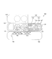
- FIG. 1 is a view showing the configuration of an emitter 10 used in contact with the inner wall surface of a tube described in Patent Document 1.
- FIG. 1A is a perspective view showing the configuration of the emitter 10
- FIG. 1B is a partially enlarged bottom view of the flow passage 20 in the emitter 10.
- the emitter 10 has a water intake 30 for taking in the irrigation liquid, an outlet 40 for discharging the irrigation liquid, and a flow passage 20 including a control passage 50 and a plurality of projections 60.
- the emitter 10 described in Patent Document 1 is used in a state where the surface on which the flow channel 20 is formed is joined to the inner surface of the tube.
- the drip irrigation tube using the emitter 10 described in Patent Document 1 can supply irrigation liquid at a desired flow rate, and is clogged by the accumulation of foreign matter such as sand grains and precipitates in the flow path 20 Can be suppressed.
- generation of a vortex flow between adjacent convex portions 60 is mentioned.
- the vortex flow is generated in a plane substantially parallel to a plane including the flow direction of the liquid in the flow path and the width direction of the flow path. It can stir only dimensionally. For this reason, the emitter described in Patent Document 1 may not be able to sufficiently prevent clogging due to deposition of foreign matter. When the clogging has occurred, it has been difficult to eliminate the clogging.
- an object of the present invention is to provide an emitter and a drip irrigation tube that can more effectively suppress clogging due to the accumulation of foreign matter in the flow path.
- the emitter according to the present invention discharges the irrigation liquid in the tube when the emitter according to the present invention is joined to the inner wall surface of the tube for circulating the irrigation liquid at a position corresponding to the outlet communicating the inside and the outside of the tube.
- a holding member for vibratably holding the emitter main body when joined to the inner wall surface of the tube, and including a communication hole for communicating the discharge port with the discharge portion of the emitter main body.
- the drip irrigation tube according to the present invention comprises a tube having a discharge port for discharging an irrigation liquid, and an emitter according to the present invention joined to a position corresponding to the discharge port on the inner wall surface of the tube; Have.
- the emitter and the tube for drip irrigation which can suppress more effectively the clogging by accumulation of the foreign material in a flow path can be provided.
- FIGS. 1A and 1B are diagrams showing the configuration of the emitter described in Patent Document 1.
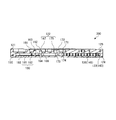
- FIG. FIG. 2 is a cross-sectional view of a drip irrigation tube according to Embodiment 1 of the present invention.
- FIG. 3 is a view showing the configuration of the emitter main body according to the first embodiment of the present invention.
- FIGS. 4A and 4B are diagrams showing the configuration of the emitter main body according to the first embodiment of the present invention.
- FIG. 5 is a cross-sectional view showing the configuration of the emitter main body according to the first embodiment of the present invention.
- 6A to 6C are schematic views for explaining the operation of the emitter main body according to the first embodiment of the present invention.
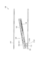
- FIG. 7 is a cross-sectional view of a drip irrigation tube according to a first modification.
- FIG. 8 is a cross-sectional view of a drip irrigation tube according to a second modification.
- FIG. 2 is a cross-sectional view in a direction along the central axis of the drip irrigation tube 100 according to the first embodiment of the present invention.
- the drip irrigation tube 100 has a tube 110 and an emitter 120.
- the tube 110 is a tube for flowing irrigation liquid.
- the direction in which the irrigation liquid flows in the tube 110 is not particularly limited.
- the material of the tube 110 is not particularly limited.
- the material of the tube 110 is polyethylene.
- the tube wall of the tube 110 is formed with a plurality of tube discharge ports 112 communicating the inside and the outside of the tube 110 for discharging the irrigation liquid at predetermined intervals (for example, 200 to 500 mm) in the axial direction of the tube 110 ing.
- the diameter of the opening of the tube discharge port 112 is not particularly limited as long as the irrigation liquid can be discharged. In the present embodiment, the diameter of the opening of the tube discharge port 112 is 1.5 mm.
- Emitters 120 are respectively bonded to positions on the inner wall surface of the tube 110 corresponding to the tube discharge port 112.
- the cross-sectional shape and cross-sectional area perpendicular to the axial direction of the tube 110 are not particularly limited as long as the emitter 120 can be disposed inside the tube 110.
- the emitter 120 has an emitter body 200 and a holding member 210.
- the emitter main body 200 has a flow path configuration portion 121 and a film 122.
- FIG. 3 is a plan view of the emitter main body 200 before the flow path configuration portion 121 and the film 122 are bonded.
- FIG. 4A is a plan view of the emitter main body 200 after the flow path configuration portion 121 and the film 122 are joined, and
- FIG. 4B is a bottom view of the emitter main body 200. However, in FIG. 4B, a bottom wall portion 190 (see FIG. 5) described later is omitted. 5 is a cross-sectional view taken along the line BB shown in FIG. 4A.
- the emitter main body 200 has a flow path configuration portion 121 and a film 122 joined to the flow path configuration portion 121.
- the flow path configuration portion 121 and the film 122 may be integrally formed or may be separately formed.
- the flow path configuration portion 121 and the film 122 are integrally formed via the hinge portion 123.
- the longitudinal direction of the emitter body 200 means the longitudinal direction when the emitter body 200 is viewed in plan, that is, the left-right direction in FIG.
- the lateral direction of the emitter body 200 means the lateral direction when the emitter body 200 is viewed in plan, that is, the vertical direction in FIG. 3.
- both the flow path configuration portion 121 and the film 122 be formed of one kind of flexible material.
- the flow path configuration portion 121 may be formed of a non-flexible material.
- the diaphragm part (the 1st diaphragm part 167 and the 2nd diaphragm part 175) mentioned later is also integrally shape
- the flow path configuration portion 121 and the film 122 including the diaphragm portion are integrally formed of one kind of flexible material.
- Examples of the material of the flow path configuration portion 121 and the film 122 include resin and rubber. Examples of resins include polyethylene and silicone.
- the flexibility of the flow path configuration portion 121 and the film 122 can be adjusted by the use of an elastic resin material. Examples of the method of adjusting the flexibility of the flow path forming portion 121 and the film 122 include selection of a resin having elasticity, adjustment of a mixture ratio of a resin material having elasticity with respect to a hard resin material, and the like.
- the integrally formed article of the flow path configuration portion 121 and the film 122 can be manufactured, for example, by injection molding.
- the flow path configuration part 121 includes a water intake part 150, a first connection groove 131 to be the first connection flow path 141, and a first pressure reduction flow path 142.
- the water intake unit 150, the flow rate reducing unit 160, and the flow path opening / closing unit 170 are disposed on the surface 125 side of the flow path forming unit 121 (emitter main body 200).
- the first connection groove 131, the first pressure reduction groove 132, the second connection groove 133, the second pressure reduction groove 134, the third pressure reduction groove 135, the discharge portion 180 and the bottom wall surface portion 190 200) is disposed on the back surface 124 side.
- the bottom wall portion 190 is a member that covers the back surface 124 side of the flow path configuration portion 121.
- the bottom wall portion 190 may be integrally molded of the same one kind of material as the other portions of the flow path forming portion 121, or may be molded separately.
- bottom wall portion 190 is integrally formed with the other portions of flow path configuration portion 121 via hinge portion 191, and bottom wall portion 190 is folded back to back surface 124 of flow path configuration portion 121.
- the bottom wall surface portion 190 covers the back surface 124 side of the flow path configuration portion 121 by being joined to the bottom surface portion.
- an emitter discharge port 192 is provided at a position corresponding to the discharge portion 180 of the emitter main body 200 and the communication hole 213 of the holding member 210.
- the emitter discharge port 192 is an opening provided in the bottom wall portion 190, and discharges the irrigation liquid taken into the interior of the emitter main body 200 to the outside of the flow path forming portion 121 (emitter main body 200).
- the first connection groove 131, the first decompression groove 132, the second connection groove 133, the second decompression groove 134, and the third decompression groove 135 can be obtained by covering the back surface 124 side of the flow path configuration portion 121 with the bottom wall surface portion 190.
- the intake portion 150, the first connection flow path 141, the first pressure reduction flow path 142, the second connection flow path 143, the second pressure reduction flow path 144, the flow rate reduction portion 160, and the discharge portion 180 A first flow path connecting the discharge unit 180 and the discharge unit 180 is formed.
- a second flow path connecting the water intake portion 150 and the discharge portion 180 is formed.
- the first flow path and the second flow path both allow irrigation liquid to flow from the water intake portion 150 to the discharge portion 180.
- the first channel and the second channel overlap between the water intake portion 150 and the second connection channel 143.
- the downstream side of the flow path opening / closing portion 170 in the second flow path is connected to the flow rate reducing portion 160, and the first flow path and the second flow path are also connected between the flow rate reducing portion 160 and the discharge portion 180.
- the water intake portion 150 is disposed in a region about half of the surface 125 of the flow path configuration portion 121 (see FIGS. 3 and 4A). In the region of the surface 125 where the water intake portion 150 is not disposed, the flow rate reduction portion 160 and the flow path opening / closing portion 170 (film 122) are disposed.
- the water intake portion 150 has a water intake side screen portion 151 and a water intake through hole 152.
- the water intake side screen unit 151 prevents foreign matter in the irrigation liquid introduced into the flow path configuration unit 121 from intruding into the water intake recess 153.
- the water intake side screen portion 151 is open to the inside of the tube 110, and has a water intake recessed portion 153, a plurality of slits 154, and a plurality of ridges 155.
- the water intake recess 153 is a single recess formed on the entire surface 125 of the flow path configuration portion 121 where the film 122 is not bonded.
- the depth of the water intake recess 153 is not particularly limited, and is appropriately set according to the size of the flow path configuration part 121.
- a plurality of slits 154 are formed on the outer peripheral wall of the water intake recess 153, and a plurality of convex strips 155 are formed on the bottom surface of the water intake recess 153. Further, a water intake through hole 152 is formed on the bottom surface of the water intake recess 153.
- the plurality of slits 154 connect the inner side surface of the water intake recess 153 to the outer side surface of the flow path configuration portion 121, and the irrigation liquid is taken into the water intake recess 153 from the side surface of the flow path configuration portion 121. Foreign matter in the irrigation liquid is prevented to some extent from entering the water intake recess 153.
- the shape of the slit 154 is not particularly limited as long as the above-described function can be exhibited. In the present embodiment, the shape of the slit 154 is formed such that the width increases from the outer surface of the flow path forming portion 121 toward the inner surface of the water intake recess 153 (see FIGS. 3 and 4A). . As described above, since the slit 154 is configured to have a so-called wedge wire structure, the pressure loss of the irrigation liquid flowing into the water intake recess 153 is suppressed.
- the plurality of ridges 155 are disposed on the bottom surface of the water intake recess 153.
- the arrangement and the number of the ridges 155 are not particularly limited as long as the water intake portion 150 can take in the irrigation liquid from the opening side of the water intake recess 153 and prevent entry of foreign matter in the irrigation liquid to some extent.
- the plurality of ridges 155 are arranged such that the longitudinal direction of the ridges 155 is along the short direction of the flow path forming portion 121.
- the ridges 155 are formed such that the width decreases from the surface 125 of the flow path configuration portion 121 toward the bottom surface of the water intake recess 153.
- the space between the adjacent ridges 155 has a so-called wedge wire structure.
- interval between the adjacent convex lines 155 will not be specifically limited if the above-mentioned function can be exhibited.
- the space between the adjacent ridges 155 is configured to have a so-called wedge wire structure, the pressure loss of the irrigation liquid flowing into the water intake recess 153 is suppressed.
- the water intake through hole 152 is formed on the bottom surface of the water intake recess 153.
- the shape and the number of the water intake through holes 152 are not particularly limited as long as the irrigation liquid taken into the water intake recess 153 can be taken into the flow path forming portion 121.
- the water intake through hole 152 is one long hole formed along the longitudinal direction of the flow path configuration portion 121 on the bottom surface of the water intake recess 153. Since the elongated hole is partially covered by the plurality of ridges 155, when viewed from the surface 125 side, the water intake through hole 152 appears to be divided into a large number of through holes.
- the irrigation liquid that has flowed in the tube 110 is taken into the flow path forming portion 121 while the foreign matter is prevented from entering the water intake recess 153 to some extent by the water intake side screen portion 151.
- the first connection groove 131 (first connection flow channel 141) connects the water intake through hole 152 (water intake portion 150) and the first decompression groove 132.
- the first connection groove 131 is formed in a straight line along the longitudinal direction of the flow path forming portion 121 at the outer edge portion of the back surface 124.
- the opening on the back surface 124 side of the first connection groove 131 is covered by the bottom wall surface portion 190, whereby the first connection channel 141 is formed.
- the irrigation liquid taken in from the water intake portion 150 flows through the first connection flow channel 141 to the first pressure reduction flow channel 142.
- the first pressure reducing groove 132 (first pressure reducing channel 142) is disposed in the first flow channel and the second flow channel on the upstream side of the flow rate reducing portion 160, and the first connection groove 131 (first connection channel 141). And the second connection groove 133 (second connection channel 143).
- the first pressure reducing groove 132 (first pressure reducing channel 142) reduces the pressure of the irrigation liquid taken in from the water intake portion 150 and leads it to the second connection groove 133 (second connecting channel 143).
- the first decompression groove 132 is linearly arranged along the longitudinal direction of the flow path forming portion 121 at the outer edge portion of the back surface 124.
- the upstream end of the first decompression groove 132 is connected to the first connection groove 131, and the downstream end of the first decompression groove 132 is connected to the upstream end of the second connection groove 133.
- the plan view shape of the first decompression groove 132 is a zigzag shape.
- the opening on the back surface 124 side of the first decompression groove 132 is covered by the bottom wall surface portion 190, whereby the first decompression channel 142 is formed.
- the irrigation liquid taken in from the water intake unit 150 is decompressed by the first pressure reduction channel 142 and is guided to the second connection groove 133 (second connection channel 143).
- the second connection groove 133 (second connection flow channel 143) includes a first pressure reduction groove 132 (first pressure reduction flow channel 142), a second pressure reduction groove 134 (second pressure reduction flow channel 144), and a third pressure reduction groove 135 It connects with the third pressure reduction channel 145).
- the second connection groove 133 is formed in a straight line along the short direction of the flow path configuration portion 121 at the outer edge portion of the back surface 124.
- the opening on the back surface 124 side of the second connection groove 133 is covered by the bottom wall surface portion 190, whereby the second connection channel 143 is formed.
- the irrigation liquid taken in from the water intake unit 150 and guided to the first connection flow channel 141 and decompressed in the first pressure reduction flow channel 142 passes through the second connection flow channel 143 to form the second pressure reduction flow channel 144 and the second pressure reduction channel 144. 3 is led to the pressure reducing channel 145.
- the second pressure reduction groove 134 (second pressure reduction channel 144) is disposed in the first flow channel on the upstream side of the flow amount reduction unit 160, and the second connection groove 133 (second connection flow channel 143) Connect with the unit 160.
- the second pressure reduction groove 134 (second pressure reduction flow path 144) reduces the pressure of the irrigation liquid flowing in from the second connection groove 133 (second connection flow path 143), and leads it to the flow rate reduction portion 160.
- the second decompression groove 134 is disposed along the longitudinal direction of the flow path forming portion 121 at the outer edge portion of the back surface 124.
- the upstream end of the second decompression groove 134 is connected to the downstream end of the second connection groove 133, and the downstream end of the second decompression groove 134 is connected to the first connection through hole 165 in communication with the flow reduction portion 160 There is.
- the shape of the second decompression groove 134 is not particularly limited as long as the above-mentioned function can be exhibited.
- the plan-view shape of the second decompression groove 134 is a zigzag shape similar to the shape of the first decompression groove 132.
- the opening on the back surface 124 side of the second decompression groove 134 is covered by the bottom wall surface portion 190, whereby the second decompression channel 144 is formed.
- the second decompression groove 134 (second decompression channel 144) is longer than a third decompression groove 135 (third decompression channel 145) described later. For this reason, the irrigation liquid flowing through the second decompression groove 134 (second decompression channel 144) is decompressed more than the irrigation liquid flowing through the third decompression channel 135 (third decompression channel 145). A portion of the irrigation liquid taken in from the water intake unit 150 and depressurized by the first depressurizing channel 142 is depressurized by the second depressurizing channel 144 and is led to the flow rate reducing unit 160.
- the third pressure reduction groove 135 (third pressure reduction channel 145) is disposed in the second flow channel on the upstream side of the flow rate reducing portion 160, and the second connection groove 133 (second connection flow channel 143) and the flow channel The opening and closing unit 170 is connected.
- the third pressure reduction groove 135 (third pressure reduction channel 145) reduces the pressure of the irrigation liquid flowing in from the second connection groove 133 (second connection channel 143) and guides the same to the flow path opening / closing portion 170.
- the third pressure reducing groove 135 is disposed in the central portion of the back surface 124 along the longitudinal direction of the flow path forming portion 121.
- the upstream end of the third decompression groove 135 is connected to the downstream end of the second connection channel 143, and the downstream end of the third decompression groove 135 is connected to the third connection through hole 174 communicated with the channel opening / closing portion 170 It is done.
- the shape of the third decompression groove 135 is not particularly limited as long as the above-mentioned function can be exhibited.
- the plan-view shape of the third decompression groove 135 is a zigzag shape similar to the shape of the first decompression groove 132.
- the opening on the back surface 124 side of the third decompression groove 135 is covered by the bottom wall surface portion 190, whereby the third decompression channel 145 is formed.
- the other part of the irrigation liquid taken in from the water intake unit 150 and depressurized by the first depressurization channel 142 is depressurized by the third depressurization channel 145 and is led to the channel opening / closing unit 170.
- the second flow path functions only when the pressure of the irrigation liquid is low.
- the flow rate reduction portion 160 is disposed between the second pressure reduction flow path 144 (second pressure reduction groove 134) and the discharge portion 180 in the first flow path, and is disposed on the surface 125 side of the flow path configuration portion 121. It is done.
- the flow rate reduction unit 160 sends the irrigation liquid to the discharge unit 180 while reducing the flow rate of the irrigation liquid according to the pressure of the irrigation liquid in the tube 110.
- the configuration of the flow rate reducing unit 160 is not particularly limited as long as the above-described function can be exhibited.
- the flow rate reducing portion 160 includes the flow rate reducing recess portion 161, the first valve seat portion 162, the communication groove 163, the flow rate reducing through hole 164 communicated with the discharge portion 180, and the second pressure reducing groove.
- the flow rate reducing recess 161 in communication with the discharge part 180, the first connection through hole 165 in fluid communication with the second pressure reducing groove 134 (second pressure reducing channel 144)
- a second connection through hole 166 communicating with the passage opening / closing through hole 173 of the passage opening / closing portion 170 is opened.
- the plan view shape of the flow rate reducing recess 161 is substantially circular.
- the flow rate reducing through hole 164 in communication with the discharge portion 180, and the first connection through hole 165 in fluid communication with the second pressure reducing groove 134 (second pressure reducing channel 144)
- a second connection through hole 166 in communication with the passage opening / closing portion 170 and a first valve seat portion 162 are disposed.
- the depth of the flow rate reducing recess 161 is not particularly limited, and may be equal to or greater than the depth of the communication groove 163.
- the flow rate reducing through hole 164 is disposed in the central portion of the bottom surface of the flow rate reducing recess 161, and communicates with the discharge portion 180.
- the first valve seat portion 162 is disposed on the bottom surface of the flow amount reduction recess 161 so as to surround the flow amount reduction through hole 164.
- the first valve seat portion 162 is formed so that the first diaphragm portion 167 can be in close contact when the pressure of the irrigation liquid flowing through the tube 110 is equal to or higher than the second pressure. When the first diaphragm portion 167 contacts the first valve seat portion 162, the flow rate of the irrigation liquid flowing from the flow rate reducing recess 161 into the discharge portion 180 is reduced.
- the shape of the first valve seat portion 162 is not particularly limited as long as the above-mentioned function can be exhibited.
- the shape of the first valve seat portion 162 is an annular convex portion.
- the height of the end surface of the annular convex portion from the bottom surface of the flow rate reduction recess 161 decreases from the inside toward the outside.
- a communication groove 163 communicating the inside of the flow rate reducing recess 161 with the flow rate reducing through hole 164 is formed in a part of the area where the first diaphragm portion 167 of the first valve seat portion 162 can be in close contact.
- the bottom surface of the flow rate reducing recess 161 is formed in a region where the first valve seat portion 162 is not disposed.
- the first connection through hole 165 in communication with the second decompression groove 134 (the second decompression channel 144) is disposed so as to be surrounded by the first valve seat portion 162, and for the flow rate reduction in communication with the discharge portion 180.
- the through hole 164 may be disposed outside the first valve seat portion 162.
- the first diaphragm portion 167 is a part of the film 122.
- the first diaphragm portion 167 is arranged to shut off the communication between the inside of the flow rate reducing recess 161 and the inside of the tube 110.
- the first diaphragm portion 167 has flexibility, and deforms to contact the first valve seat portion 162 according to the pressure of the irrigation liquid in the tube 110. Specifically, as the pressure of the irrigation liquid increases, the first diaphragm portion 167 deforms toward the first valve seat portion 162 and eventually contacts the first valve seat portion 162.
- the first diaphragm portion 167 is in close contact with the first valve seat portion 162, the first diaphragm portion 167 closes the first connection through hole 165, the flow rate reduction through hole 164, and the communication groove 163. Therefore, the irrigation liquid sent from the first connection through hole 165 can be sent to the discharge part 180 through the communication groove 163 and the flow rate reduction through hole 164.
- the first diaphragm portion 167 is disposed adjacent to a second diaphragm portion 175 described later.
- the flow path opening / closing portion 170 is disposed between the third pressure reduction flow path 145 (the third pressure reduction groove 135) and the discharge portion 180 in the second flow path, and on the surface 125 side of the flow path configuration portion 121. It is arranged.
- the flow path opening / closing unit 170 opens the second flow path according to the pressure in the tube 110 and sends the irrigation liquid to the discharge unit 180.
- the flow path opening / closing portion 170 is connected to the flow reduction portion 160 via the flow path opening / closing through hole 173 and the second connection through hole 166, and the third pressure reduction flow path 145 (third The irrigation liquid from the decompression groove 135) reaches the discharge part 180 through the flow path opening / closing part 170 and the flow rate reducing part 160.
- the configuration of the flow path opening / closing portion 170 is not particularly limited as long as the above-described function can be exhibited.
- the flow path opening / closing portion 170 communicates with the flow path opening / closing concave portion 171, the second valve seat portion 172, and the second connection through hole 166 of the flow rate reducing portion 160.
- a third connection through hole 174 communicated with the third pressure reduction channel 145 (third pressure reduction groove 135) and a second diaphragm portion 175 which is a part of the film 122 are provided.
- the plan view shape of the flow path opening / closing concave portion 171 is a substantially circular shape.
- a third connection through hole 174 connected to the third decompression groove 135, a flow path opening / closing through hole 173 connected to the flow reduction portion 160, and a second valve seat are provided on the bottom of the flow path opening / closing recess 171.
- Part 172 is arranged.
- the end face of the second valve seat portion 172 is disposed closer to the surface 125 than the end face of the first valve seat portion 162. That is, the second valve seat portion 172 is formed higher than the first valve seat portion 162.
- the third connection through hole 174 in communication with the third decompression groove 135 is formed on the bottom surface of the passage opening / closing recess 171 in a region where the second valve seat portion 172 is not disposed.
- the second valve seat portion 172 is disposed on the bottom surface of the passage opening / closing recess 171 so as to surround the passage opening / closing hole 173. Further, the second valve seat portion 172 is disposed in non-contacting manner facing the second diaphragm portion 175, and when the pressure of the irrigation liquid flowing through the tube 110 is equal to or higher than the first pressure, the second diaphragm portion 175 can be in close contact It is formed as.
- the second diaphragm 175 When the pressure of the irrigation liquid flowing through the tube 110 is equal to or higher than the first pressure, the second diaphragm 175 is in close contact with the second valve seat 172 to close the passage opening / closing through hole 173, resulting in the second Block the flow path.
- the shape of the second valve seat portion 172 is not particularly limited as long as the above-described function can be exhibited.
- the second valve seat portion 172 is an annular convex portion disposed so as to surround the flow path opening / closing through hole 173.
- the second diaphragm portion 175 is a part of the film 122 and is disposed adjacent to the first diaphragm portion 167.
- the second diaphragm portion 175 is disposed to block communication between the inside of the flow path opening / closing recess 171 and the inside of the tube 110.
- the second diaphragm portion 175 is flexible and deforms to contact the second valve seat portion 172 according to the pressure of the irrigation liquid in the tube 110. Specifically, as the pressure of the irrigation liquid increases, the second diaphragm portion 175 deforms toward the second valve seat portion 172, and when the pressure of the irrigation liquid reaches the first pressure, the second valve Contact the seat portion 172. Thereby, the second flow passage (flow passage opening / closing through hole 173) is closed.
- the discharge unit 180 is disposed on the back surface 124 side of the flow path configuration unit 121 so as to face a holding member 210 described later.
- the discharge unit 180 sends the irrigation liquid from the flow rate reduction through hole 164 to the tube discharge port 112 of the tube 110 via the holding member 210.
- the discharge unit 180 can discharge the irrigation liquid to the outside of the emitter 120.
- the configuration of the discharge unit 180 is not particularly limited as long as the above-described function can be exhibited.
- the discharge portion 180 has a discharge concave portion 181 and an intrusion prevention portion 182.
- the discharge recess 181 is disposed on the back surface 124 side of the flow path configuration portion 121.
- the plan view shape of the discharge concave portion 181 is substantially rectangular.
- a flow rate reduction through hole 164 and an intrusion prevention portion 182 are disposed on the bottom surface of the discharge recess 181.
- the opening on the back surface 124 side of the discharge recess 181 is covered by the bottom wall portion 190, and the bottom wall portion 190 is provided with the emitter discharge port 192.
- the entry prevention unit 182 prevents entry of foreign matter from the outside of the tube 110 via the tube outlet 112.
- the intrusion prevention unit 182 is not particularly limited as long as the function described above can be exhibited.
- the intrusion prevention portion 182 has two convex streaks 184 disposed adjacent to each other. The two ridges 184 are disposed so as to be located between the flow rate reducing through hole 164 and the emitter discharge port 192.
- the film 122 has a first diaphragm portion 167 and a second diaphragm portion 175 (see FIG. 3).
- the thickness of the film 122 is, for example, 0.3 mm.
- the hinge portion 123 is connected to a part of the surface 125 of the flow path forming portion 121.
- the thickness of the hinge portion 123 is the same as that of the film 122, and is integrally formed with the flow path configuration portion 121 and the film 122.
- the film 122 may be prepared separately from the flow path forming portion 121 and may be bonded to the flow path forming portion 121.
- the emitter main body 200 is configured by rotating the film 122 about the hinge portion 123 and bonding it to the surface 125 of the flow path configuration portion 121.
- Examples of a method of joining the flow path configuration part 121 and the film 122 include welding of a resin material that constitutes the film 122, adhesion with an adhesive, and the like.
- the hinge part 123 may be cut
- the bottom wall portion 190 has an emitter outlet 192 (see FIGS. 3 and 4B).
- the thickness of bottom wall portion 190 is, for example, 0.7 mm.
- the hinge portion 191 is connected to a part of the back surface 124 of a portion other than the bottom wall surface portion 190 of the flow path configuration portion 121.
- the thickness of the hinge portion 191 is the same as that of the bottom wall portion 190, and is integrally formed with the back surface 124 and the bottom wall portion 190.
- the bottom wall portion 190 may be prepared as a separate body (for example, a film or the like) from a portion other than the bottom wall portion 190 of the flow path configuration portion 121 and may be joined to the back surface 124.
- the flow path configuration portion 121 is configured by rotating the bottom wall surface portion 190 about the hinge portion 191 as a shaft and bonding the bottom wall surface portion 190 to the back surface 124 of the flow path configuration portion 121.
- the method of joining the back surface 124 and the bottom wall portion 190 is not particularly limited. Examples of the method of joining the back surface 124 and the bottom wall portion 190 include welding of the resin material constituting the bottom wall portion 190, adhesion with an adhesive, and the like.
- the hinge portion 191 may be cut after the back surface 124 and the bottom wall surface portion 190 are joined.
- the holding member 210 is joined at a position corresponding to the tube discharge port 112 on the inner wall surface of the tube 110, and holds the emitter body 200 in a vibratable manner.
- the holding member 210 preferably has the following three features in order to vibratably hold the emitter body 200.
- the holding member 210 is opposed to the lower surface 212 of the holding member 210, that is, the surface to be joined to the tube 110 in a cross section along the longitudinal direction of the emitter body 200.
- the emitter body 200 is held so that the emitter body 200 is inclined.
- the holding member 210 has an upper surface 211 and a lower surface 212.
- the upper surface 211 is the upper surface of the holding member 210 in FIG. 2, ie, the surface to be bonded to the emitter body 200, and the lower surface 212 is bonded to the lower surface of the holding member 210 in FIG. It is a face.
- At least one of the front surface 125 and the back surface 124 of the emitter body 200 is inclined to the flow of the irrigation liquid in the tube 110. For this reason, at least one of the front surface 125 and the back surface 124 of the emitter body 200 is hit by the irrigation liquid flowing in the tube 110, and the pressure by it is applied.
- the angle at which the emitter body 200 is inclined with respect to the axial direction of the tube 110 is not particularly limited. Further, as described above, the direction of the irrigation liquid flowing in the tube 110 is not particularly limited.
- the holding member 210 preferably holds the emitter body 200 so that the emitter body 200 does not contact the inner wall surface of the tube 110.
- the emitter main body 200 comes into contact with the inner wall surface of the tube 110, so that it is possible to avoid that the emitter main body 200 is not easily vibrated even when pressure is applied by the flow of the irrigation liquid.
- the holding member 210 is preferably formed of a flexible material.
- the holding member 210 may be integrally formed of the same material as the emitter body 200 (the flow path forming portion 121 and the film 122), or may be separately formed of a different material.
- the upper surface 211 of the holding member 210 is the bottom wall surface portion 190 of the discharge portion 180, and the bottom wall surface portion 190 other than the discharge portion 180 is a separate body (for example, , Film, etc.).
- the method of bonding the emitter body 200 and the holding member 210 is not particularly limited. Moreover, it does not specifically limit about the joining method of the holding member 210 and the tube 110, either. Examples of the method of bonding the emitter main body 200 and the holding member 210 and the method of bonding the holding member 210 and the tube 110 include welding of a resin material constituting the holding member 210, adhesion with an adhesive, and the like.
- the holding member 210 has a communication hole 213.
- the communication hole 213 has an opening on the upper surface 211 and the lower surface 212 of the holding member 210, and is a hole provided so as to penetrate the holding member 210.
- one (upper surface 211 side) of the communication hole 213 is connected to the emitter discharge port 192, and the other (lower surface 212 side) Is connected to the tube outlet 112.
- the discharge portion 180 and the tube discharge port 112 communicate with each other, and the irrigation liquid discharged from the emitter discharge port 192 is discharged from the tube discharge port 112 to the outside of the tube 110 through the communication hole 213.
- the communication hole 213 may be provided simultaneously with the formation of the holding member 210, and the flow path forming portion 121 is the tube 110 by the holding member 210. It may be provided after being fixed to That is, after the holding member 210 formed without providing the communication hole 213 is joined to the tube 110, the communication hole 213 may be provided to communicate the discharge portion 180 and the tube discharge port 112.
- the holding member 210 may be provided in advance at a position corresponding to the tube discharge port 112 when the tube 110 is manufactured. In this case, the holding member 210 holds the emitter body 200 by bonding the separately manufactured emitter body 200 to the holding member 210.
- the lower surface 212 side of the holding member 210 is convex toward the inner wall surface of the tube 110 along the inner wall surface of the tube 110.
- it is formed in a substantially arc shape.
- the irrigation liquid is fed into the tube 110.
- irrigation liquids include water, liquid fertilizers, pesticides and mixtures thereof.
- the pressure of the irrigation liquid sent to the drip irrigation tube 100 is preferably 0.1 MPa or less so that the drip irrigation method can be easily introduced and the breakage of the tube 110 and the emitter 120 can be prevented.
- the irrigation liquid in the tube 110 is taken into the emitter body 200 from the water intake 150. Specifically, the irrigation liquid in the tube 110 enters the water intake recess 153 from the slit 154 or the gap between the ridges 155 and passes through the water intake through hole 152.
- the water intake portion 150 has the water intake side screen portion 151 (the gap between the slit 154 and the ridges 155), it is possible to prevent the entry of foreign matter in the irrigation liquid to some extent. Further, since a so-called wedge wire structure is formed in the water intake portion 150, the pressure loss of the irrigation liquid flowing into the water intake portion 150 is suppressed.
- the irrigation liquid taken in from the water intake portion 150 reaches the first connection channel 141.
- the irrigation liquid having reached the first connection channel 141 reaches the second connection channel 143 while being depressurized by the first pressure reduction channel 142.
- the irrigation liquid that has reached the second connection flow channel 143 flows into the second pressure reduction flow channel 144 and the third pressure reduction flow channel 145, and is decompressed.
- the irrigation liquid travels in advance of the third pressure reduction flow path 145 having a short flow path length and less pressure loss as compared with the second pressure reduction flow path 144.
- the irrigation liquid that has flowed into the third pressure reduction flow path 145 flows into the flow path opening / closing portion 170 through the third connection through hole 174.
- the irrigation liquid flowing into the flow path opening / closing portion 170 flows into the flow rate reducing portion 160 through the flow path opening / closing through hole 173 and the second connection through hole 166.
- the irrigation liquid that has flowed into the flow rate reduction portion 160 flows into the discharge portion 180 through the flow rate reduction through hole 164.
- the irrigation liquid flowing into the discharge portion 180 is discharged out of the tube 110 through the emitter discharge port 192, the communication hole 213 of the holding member 210, and the tube discharge port 112 of the tube 110.
- the irrigation liquid that has flowed into the second pressure reduction flow path 144 flows into the flow rate reduction portion 160 through the first connection through hole 165.
- the irrigation liquid that has flowed into the flow rate reducing portion 160 flows into the discharge portion 180 through the flow rate reducing through hole 164.
- the irrigation liquid flowing into the discharge unit 180 is discharged out of the tube 110 through the emitter discharge port 192, the communication hole 213 of the holding member 210, and the tube discharge port 112 of the tube 110.
- the flow path opening / closing portion 170 and the flow rate reduction portion 160 communicate with each other via the flow path opening / closing through hole 173 and the second connection through hole 166. Further, in the flow rate reducing portion 160, the flow rate of the irrigation liquid is controlled by the deformation of the first diaphragm portion 167 according to the pressure of the irrigation liquid in the tube 110, and in the flow path opening / closing portion 170, the inside of the tube 110 is The flow rate of the irrigation liquid is controlled by the deformation of the second diaphragm portion 175 according to the pressure of the irrigation liquid. Therefore, the operations of the flow rate reducing unit 160 and the flow path opening / closing unit 170 according to the pressure of the irrigation liquid in the tube 110 will be described.
- 6A to 6C are schematic diagrams showing the relationship between the flow rate reducing unit 160 and the flow path opening / closing unit 170.
- 6A to 6C are schematic cross sections taken along the line BB shown in FIG. 4A.
- 6A is a cross-sectional view in the case where the irrigation liquid is not fed to the tube 110
- FIG. 6B is a cross-sectional view in the case where the pressure of the irrigation liquid in the tube 110 is the first pressure
- 6C is a cross-sectional view in a case where the pressure of the irrigation liquid in the tube 110 is a second pressure exceeding the first pressure.
- the pressure of the irrigation liquid is not applied to the film 122, so the first diaphragm portion 167 and the second diaphragm portion 175 are not deformed (see FIG. 6A). .
- the first diaphragm portion 167 of the flow reduction portion 160 begins to deform toward the first valve seat portion 162.
- the second diaphragm portion 175 of the flow path opening / closing portion 170 starts to deform toward the second valve seat portion 172.
- the first diaphragm portion 167 is not in close contact with the first valve seat portion 162, and the second diaphragm portion 175 is not in intimate contact with the second valve seat portion 172.
- the first irrigation channel (the first connection channel 141, the first pressure reduction channel 142, the second connection channel 143, the second pressure reduction channel 144, the flow reduction unit 160 and the discharge unit 180) Both of the second flow paths (the first connection flow path 141, the first pressure reduction flow path 142, the second connection flow path 143, the third pressure reduction flow path 145, the flow path opening and closing portion 170, the flow rate reduction portion 160 and the discharge portion 180) And is discharged to the outside of the flow path configuration part 121.
- the irrigation liquid taken from the water intake 150 is It is discharged through both the first flow path and the second flow path.
- the first diaphragm portion 167 and the second diaphragm portion 175 further deform. Then, the second diaphragm portion 175 contacts the second valve seat portion 172 to close the second flow path (see FIG. 6B). At this time, since the end face of the second valve seat portion 172 is disposed closer to the surface 125 than the end face of the first valve seat portion 162, the first diaphragm portion 167 of the second diaphragm portion 175 is the first valve seat portion Prior to contacting 162, the second valve seat portion 172 is contacted. At this time, the first diaphragm portion 167 is not in contact with the first valve seat portion 162.
- the second diaphragm portion 175 is brought close to the second valve seat portion 172, so the fluid is discharged through the second flow path.
- the volume of irrigation fluid decreases.
- the pressure of the irrigation liquid in the tube 110 reaches the first pressure, the irrigation liquid in the second flow path is not discharged to the outside of the flow path forming portion 121.
- the irrigation liquid introduced from the water intake portion 150 is discharged to the outside of the flow path forming portion 121 only through the first flow path.
- the first diaphragm portion 167 When the pressure of the irrigation liquid in the tube 110 further increases, the first diaphragm portion 167 further deforms toward the first valve seat portion 162. Normally, as the pressure of the irrigation liquid increases, the amount of irrigation liquid flowing in the first channel should increase. However, in the emitter 120 according to the present embodiment, the first depressurizing channel 142 and the first depressurizing channel 142 2) The pressure of the irrigation liquid is reduced by the pressure reduction channel 144, and the distance between the first diaphragm portion 167 and the first valve seat portion 162 is narrowed, so that the amount of the irrigation liquid flowing in the first channel is excessive. It is preventing the increase.
- the first diaphragm portion 167 contacts the first valve seat portion 162 (see FIG. 6C). Even in this case, since the first diaphragm portion 167 does not close the first connection through hole 165, the flow rate reduction through hole 164 and the communication groove 163, the irrigation liquid taken from the water intake portion 150 is communicated The fluid is discharged to the outside of the flow path forming portion 121 through the groove 163. As described above, when the pressure of the irrigation liquid in the tube 110 is equal to or higher than the second pressure, the flow rate reducing unit 160 causes the first diaphragm portion 167 to contact the first valve seat portion 162, whereby the first flow path is formed. Control the increase in the volume of irrigation fluid flowing through the
- the flow rate reducing unit 160 and the flow path opening / closing unit 170 function so that the amounts of fluid flowing therethrough are mutually complemented in accordance with the pressure of the irrigation liquid in the tube 110.
- the drip irrigation tube according to the present invention can discharge a fixed amount of irrigation liquid out of the tube 110 regardless of whether the pressure of the irrigation liquid is low pressure or high pressure.
- the pressure of the irrigation liquid is applied to at least one of the front surface 125 and the back surface 124 of the emitter main body 200, whereby the emitter main body 200 supports the holding member 210. Vibrate as.
- the direction in which the emitter body 200 vibrates is not particularly limited. In the present embodiment, the emitter main body 200 vibrates in the vertical direction in FIG.
- the following effects can be obtained.
- the foreign matter such as sand grains and precipitates are present in the irrigation liquid
- the foreign matter hardly enters the emitter 200 because of the vibration of the emitter 200.
- the foreign substance which has penetrated due to the vibration of the emitter main body 200 does not stay in the emitter main body 200.
- the vibration of the emitter main body 200 continues throughout the flow of the irrigation liquid, so that the occurrence (clogging) of foreign matter in the flow path of the emitter main body 200 can be suitably suppressed and eliminated.
- the holding member 210 preferably has three features in order to hold the emitter main body 200 in a vibratable manner, the present invention is not limited to this. That is, the holding member 210 does not have to include all the three features described above.
- the emitter 120 includes the emitter main body 200 and the holding member 210 that holds the emitter main body 200 in a vibratable manner.
- the holding member 210 holds the emitter main body 200 such that the emitter main body 200 is inclined with respect to the lower surface 212 of the holding member 210, that is, the surface joined to the tube 110 in a cross section along the longitudinal direction of the emitter main body 200.
- the pressure of the irrigation liquid is suitably applied to at least one of the front surface 125 and the back surface 124 of the emitter main body 200, so that the emitter main body 200 vibrates suitably.
- the holding member 210 holds the emitter body 200 so that the emitter body 200 does not contact the inner wall surface of the tube 110. As a result, the emitter main body 200 comes into contact with the inner wall surface of the tube 110, so that it is possible to avoid that the emitter main body 200 is not easily vibrated even when pressure is applied by the flow of the irrigation liquid.
- the holding member 210 is formed of a flexible material. Thereby, the emitter main body 200 vibrates suitably with the holding member 210 as a fulcrum.
- the emitter main body 200 vibrates with the holding member 210 as a fulcrum, so foreign substances in the irrigation liquid are contained in the emitter main body 200. It is hard to get in. Furthermore, even if foreign matter intrudes into the emitter main body 200, the foreign matter is discharged to the outside of the emitter main body 200 by this vibration. For this reason, the situation (clogging) in which foreign matter is accumulated in the flow path of the emitter main body 200 can be suitably suppressed and eliminated.
- the holding member 210 described in the first embodiment is an example, and the emitter according to the present invention is not limited to this aspect.
- the emitter body 200 may be held by a holding member 210 ⁇ / b> A having a simpler configuration (Modification 1).
- FIG. 7 is a view for explaining a holding member 210A according to the first modification of the present invention.
- the holding member 210A is such that the emitter body 200 is inclined with respect to the surface (lower surface) of the holding member 210A to be joined to the tube 110 in a cross section along the longitudinal direction of the emitter main body 200. And, the emitter body 200 is held so that the emitter body 200 does not come in contact with the inner wall surface of the tube 110.
- the holding member 210A is formed in a cylindrical shape (tubular shape), and has a communication hole 213A inside the cylinder.
- One end of the communication hole 213A is connected to the discharge portion 180 of the emitter main body 200 (flow path forming portion 121), and the other end is connected to the tube discharge port 112 of the tube 110, whereby the emitter discharge port 192 and the tube discharge port 112 are formed. And communicate with each other.
- the irrigation liquid discharged from the emitter discharge port 192 is discharged from the tube discharge port 112 to the outside of the tube 110 through the communication hole 213A.
- the holding member 210A is formed of a flexible material as in the above embodiment.
- the holding member 210A may be integrally formed of the same material as the emitter main body 200 (the flow path forming portion 121 and the film 122) as long as the holding member 210A is formed of a material having flexibility. It may be formed in the body.
- a method of bonding the emitter main body 200 and the holding member 210A is not particularly limited. Moreover, it does not specifically limit about the joining method of 210 A of holding members, and the tube 110, either.
- the bonding method of the holding member 210A and the emitter main body 200 and the bonding method of the holding member 210A and the tube 110 include welding of a resin material constituting the holding member 210A, adhesion with an adhesive, and the like.
- the communication hole 213A may be formed simultaneously with the formation of the holding member 210A, or it is first formed in a cylindrical shape, and both ends of the cylinder are emitters.
- the holding member 210A may be configured by opening the communication hole 213A. That is, after a cylindrical member provided at a position corresponding to the emitter discharge port 192 of the flow path forming portion 121 is joined to the tube 110, the column shape member is connected to connect the emitter discharge port 192 and the tube discharge port 112.
- the cylindrical holding member 210A may be formed by opening the communication hole 213A along the central axis.
- the holding member 210A may be provided in advance at a position corresponding to the tube discharge port 112 when the tube 110 is manufactured, and the separately manufactured emitter main body 200 may be joined to the holding member 210A.
- the holding member 210A since the holding member 210A is formed in a cylindrical shape, the holding member 210A holds the emitter main body 200 in comparison with the holding member 210A of the above embodiment.
- the bonding area is smaller than that of the first embodiment.
- the emitter main body 200 is more easily vibrated as compared with the first embodiment, and the intrusion of foreign substances into the emitter main body 200 is suitably prevented, and the invaded foreign substances are efficiently emitted to the emitter main body. It can be discharged to the outside of 200.
- the emitter according to the present invention may adopt an aspect in which the wing portion 220 is provided on the emitter body 200 as shown in FIG. Modification 2).
- the configuration other than the wing portion 220 is the same as that of the first modification.
- the wing portion 220 is a member for receiving the flow of the irrigation liquid and receiving pressure, and is provided, for example, to project from the bottom wall portion 190 of the emitter body 200 in a direction different from the longitudinal direction of the emitter body 200.
- the protruding direction of the wing portion 220 is not particularly limited.
- the wing part 220 is provided so that it may protrude from the back surface 124 side of the emitter main body 200 (flow-path structure part 121) in FIG. 8, this invention is not limited to this.
- the length (the distance from the emitter body 200) and the width (the width of the wing 220 parallel to the short direction of the emitter body 200) of the wing 220 are not particularly limited.
- the length of the wing portion 220 is preferably such that the tip of the wing portion 220 does not contact the inner wall surface of the tube 110 even if the emitter body 200 vibrates. Further, the width of the wing portion 220 is preferably equal to or less than the width of the emitter main body 200 in the width direction, which is sufficient to sufficiently receive the irrigation liquid and receive the pressure thereof.
- the surface of the wing portion 220 close to the upstream side of the irrigation liquid is referred to as a first surface 221, and the surface close to the downstream side is referred to as a second surface 222.
- the whole of the emitter main body 200 uses the holding member 210A as a fulcrum than the first modification. It becomes easy to vibrate.
- the present invention it is possible to preferably prevent the entry of foreign matter into the emitter main body by vibration, and easily provide an emitter capable of suitably discharging the entering foreign matter. Therefore, the spread of the above-mentioned emitter to the technical field which requires long-term dripping, such as drip irrigation and endurance test, and the further development of the technical field are expected.
Landscapes
- Life Sciences & Earth Sciences (AREA)
- Soil Sciences (AREA)
- Engineering & Computer Science (AREA)
- Water Supply & Treatment (AREA)
- Environmental Sciences (AREA)
- Nozzles (AREA)
Abstract
エミッタは、灌漑用液体を流通させるチューブの内壁面の、前記チューブの内外を連通する吐出口に対応する位置に接合されたときに、前記チューブ内の前記灌漑用液体を前記吐出口から定量的に前記チューブ外に吐出する。前記エミッタは、前記チューブ内の前記灌漑用液体を取り入れて吐出部から定量的に前記灌漑用液体を吐出するエミッタ本体と、前記チューブの前記吐出口と前記エミッタ本体の前記吐出部とを連通するための連通孔を含み、前記チューブの内壁面に接合されたときに前記エミッタ本体を振動可能に保持するための保持部材と、を有する。
Description
本発明は、エミッタおよび前記エミッタを有する点滴灌漑用チューブに関する。
植物の栽培方法の一つとして点滴灌漑法が知られている。点滴灌漑法とは、植物が植えられている土壌に点滴灌漑用チューブを配置し、点滴灌漑用チューブから土壌へ、水や液体肥料などの灌漑用液体を滴下する方法である。近年、点滴灌漑法は、灌漑用液体の消費量を最小限にすることが可能であるため、特に注目されている。
点滴灌漑用チューブは、通常、灌漑用液体を吐出するための複数の貫通孔が形成されたチューブと、各貫通孔から灌漑用液体を吐出するための複数のエミッタ(「ドリッパ」ともいう)とを有する。エミッタの種類としては、チューブの内壁面に接合して使用されるエミッタ(例えば、特許文献1参照)と、チューブに外側から突き刺して使用されるエミッタとが知られている。
図1は、特許文献1に記載されている、チューブの内壁面に接合して使用されるエミッタ10の構成を示す図である。図1Aは、エミッタ10の構成を示す斜視図であり、図1Bは、エミッタ10における流路20の部分拡大底面図である。エミッタ10は、灌漑用液体を取り入れるための取水口30と、灌漑用液体を排出するための排出口40と、制御路50および複数の凸部60を含む流路20と、を有する。
特許文献1に記載のエミッタ10は、流路20が形成されている面がチューブの内面に接合された状態で使用される。特許文献1に記載のエミッタ10を使用した点滴灌漑用チューブは、所望の流量で灌漑用液体を供給することができるとともに、流路20内に砂粒や沈殿物などの異物が堆積することによる詰まりを抑制することができる。特許文献1には、詰まりが抑制される理由の1つとして、隣接する凸部60間で渦流が発生することが挙げられている。
しかしながら、特許文献1に記載のエミッタでは、渦流は、流路内の液体の流れ方向と流路の幅方向とを含む平面に略平行な面内で発生するため、流路内の液体を二次元的にしか撹拌することができない。このため、特許文献1に記載のエミッタでは、異物の堆積による詰まりを十分に防止することができないことがある。詰まりが生じてしまった場合には、その詰まりを解消することが困難であった。
そこで、本発明の目的は、流路内における異物の堆積による詰まりを、より効果的に抑制することができるエミッタおよび点滴灌漑用チューブを提供することである。
本発明に係るエミッタは、灌漑用液体を流通させるチューブの内壁面の、前記チューブの内外を連通する吐出口に対応する位置に接合されたときに、前記チューブ内の前記灌漑用液体を前記吐出口から定量的に前記チューブ外に吐出するためのエミッタであって、前記チューブ内の前記灌漑用液体を取り入れて吐出部から定量的に前記灌漑用液体を吐出するエミッタ本体と、前記チューブの前記吐出口と前記エミッタ本体の前記吐出部とを連通するための連通孔を含み、前記チューブの内壁面に接合されたときに前記エミッタ本体を振動可能に保持するための保持部材と、を有する。
本発明に係る点滴灌漑用チューブは、灌漑用液体を吐出するための吐出口を有するチューブと、前記チューブの内壁面の前記吐出口に対応する位置に接合された、本発明に係るエミッタと、を有する。
本発明によれば、流路における異物の堆積による詰まりを、より効果的に抑制することができるエミッタおよび点滴灌漑用チューブを提供することができる。
以下、本発明の実施の形態について、図面を参照して詳細に説明する。
[実施の形態1]
(点滴灌漑用チューブの構成)
図2は、本発明の実施の形態1に係る点滴灌漑用チューブ100の中心軸に沿う方向における断面図である。
(点滴灌漑用チューブの構成)
図2は、本発明の実施の形態1に係る点滴灌漑用チューブ100の中心軸に沿う方向における断面図である。
図2に示されるように、点滴灌漑用チューブ100は、チューブ110およびエミッタ120を有する。
チューブ110は、灌漑用液体を流すための管である。チューブ110において、灌漑用液体を流す方向は、特に限定されない。また、チューブ110の材料は、特に限定されない。本実施の形態では、チューブ110の材料は、ポリエチレンである。チューブ110の管壁には、チューブ110の軸方向において所定の間隔(例えば、200~500mm)で、灌漑用液体を吐出するためにチューブ110の内外を連通する複数のチューブ吐出口112が形成されている。チューブ吐出口112の開口部の直径は、灌漑用液体を吐出することができれば特に限定されない。本実施の形態では、チューブ吐出口112の開口部の直径は、1.5mmである。チューブ110の内壁面のチューブ吐出口112に対応する位置には、エミッタ120がそれぞれ接合される。チューブ110の軸方向に垂直な断面形状および断面積は、チューブ110の内部にエミッタ120を配置することができれば特に限定されない。
(エミッタの構成)
エミッタ120は、エミッタ本体200と、保持部材210と、を有する。エミッタ本体200は、流路構成部121とフィルム122とを有する。図3は、流路構成部121とフィルム122とが接合される前のエミッタ本体200の平面図である。図4Aは、流路構成部121とフィルム122とを接合した後のエミッタ本体200の平面図であり、図4Bは、エミッタ本体200の底面図である。ただし、図4Bでは、後述する底壁面部190(図5参照)は省略されている。また、図5は、図4Aに示されるB-B線の断面図である。
エミッタ120は、エミッタ本体200と、保持部材210と、を有する。エミッタ本体200は、流路構成部121とフィルム122とを有する。図3は、流路構成部121とフィルム122とが接合される前のエミッタ本体200の平面図である。図4Aは、流路構成部121とフィルム122とを接合した後のエミッタ本体200の平面図であり、図4Bは、エミッタ本体200の底面図である。ただし、図4Bでは、後述する底壁面部190(図5参照)は省略されている。また、図5は、図4Aに示されるB-B線の断面図である。
図3に示されるように、エミッタ本体200は、流路構成部121と、流路構成部121に接合されたフィルム122とを有する。流路構成部121およびフィルム122は、一体として形成されていてもよいし、別体として形成されていてもよい。本実施の形態では、流路構成部121およびフィルム122は、ヒンジ部123を介して一体的に形成されている。
なお、本発明において、エミッタ本体200の長手方向とは、エミッタ本体200を平面視した場合の長手方向、すなわち図3における左右方向を意味する。同様に、エミッタ本体200の短手方向とは、エミッタ本体200を平面視した場合の短手方向、すなわち図3における上下方向を意味する。
流路構成部121およびフィルム122は、いずれも可撓性を有する一種類の材料で成形されていることが好ましい。しかし、流路構成部121およびフィルム122が別体として形成されている場合には、流路構成部121は、可撓性を有しない材料で成形されていてもよい。また、後述するダイヤフラム部(第1ダイヤフラム部167および第2ダイヤフラム部175)も、フィルム122の一部として一体的に成形されていることが好ましい。本実施の形態では、流路構成部121と、ダイヤフラム部を含むフィルム122とは、可撓性を有する一種類の材料で一体的に形成されている。
流路構成部121およびフィルム122の材料の例には、樹脂およびゴムが含まれる。樹脂の例には、ポリエチレンおよびシリコーンが含まれる。流路構成部121およびフィルム122の可撓性は、弾性を有する樹脂材料の使用によって調整することができる。流路構成部121およびフィルム122の可撓性の調整方法の例には、弾性を有する樹脂の選択や、硬質の樹脂材料に対する弾性を有する樹脂材料の混合比の調整などが含まれる。流路構成部121およびフィルム122の一体成形品は、例えば、射出成形によって製造できる。
図3~図5に示されるように、本実施の形態に係る流路構成部121は、取水部150と、第1接続流路141となる第1接続溝131と、第1減圧流路142となる第1減圧溝132と、第2接続流路143となる第2接続溝133と、第2減圧流路144となる第2減圧溝134と、第3減圧流路145となる第3減圧溝135と、流量減少部160と、流路開閉部170と、吐出部180と、底壁面部190と、を有する。取水部150、流量減少部160および流路開閉部170は、流路構成部121(エミッタ本体200)の表面125側に配置されている。また、第1接続溝131、第1減圧溝132、第2接続溝133、第2減圧溝134、第3減圧溝135、吐出部180および底壁面部190は、流路構成部121(エミッタ本体200)の裏面124側に配置されている。
図3および5に示すように、底壁面部190は、流路構成部121の裏面124側を覆う部材である。底壁面部190は、流路構成部121のその他の部分と同じ一種類の材料で一体的に成型されていてもよく、別体として成形されていてもよい。本実施の形態では、底壁面部190がヒンジ部191を介して流路構成部121のその他の部分と一体的に形成されており、底壁面部190を折り返して流路構成部121の裏面124に接合されることで、底壁面部190は流路構成部121の裏面124側を覆っている。なお、底壁面部190において、エミッタ本体200の吐出部180および保持部材210の連通孔213に対応する箇所には、エミッタ吐出口192が設けられている。エミッタ吐出口192は、底壁面部190に設けられた開口であり、エミッタ本体200の内部に取り入れられた灌漑用液体を流路構成部121(エミッタ本体200)の外部に吐出する。
流路構成部121の裏面124側が底壁面部190で覆われることにより、第1接続溝131、第1減圧溝132、第2接続溝133、第2減圧溝134および第3減圧溝135は、それぞれ第1接続流路141、第1減圧流路142、第2接続流路143、第2減圧流路144および第3減圧流路145となる。これにより、取水部150、第1接続流路141、第1減圧流路142、第2接続流路143、第2減圧流路144、流量減少部160および吐出部180から構成され、取水部150と吐出部180とを繋ぐ第1流路が形成される。また、取水部150、第1接続流路141、第1減圧流路142、第2接続流路143、第3減圧流路145、流路開閉部170、流量減少部160および吐出部180から構成され、取水部150と吐出部180とを繋ぐ第2流路が形成される。第1流路および第2流路は、いずれも取水部150から吐出部180まで灌漑用液体を流通させる。本実施の形態では、取水部150から第2接続流路143までの間は、第1流路と第2流路とが重複している。また、第2流路における流路開閉部170の下流側は、流量減少部160に接続されており、流量減少部160から吐出部180までの間も、第1流路と第2流路とが重複している。
取水部150は、流路構成部121の表面125の約半分の領域に配置されている(図3および図4A参照)。取水部150が配置されていない表面125の領域には、流量減少部160および流路開閉部170(フィルム122)が配置されている。取水部150は、取水側スクリーン部151および取水用貫通孔152を有する。
取水側スクリーン部151は、流路構成部121に取り入れられる灌漑用液体中の異物が取水用凹部153内に侵入することを防止する。取水側スクリーン部151は、チューブ110内に対して開口しており、取水用凹部153、複数のスリット154および複数の凸条155を有する。
取水用凹部153は、流路構成部121の表面125において、フィルム122が接合されていない領域の全体に形成されている1つの凹部である。取水用凹部153の深さは特に限定されず、流路構成部121の大きさによって適宜設定される。取水用凹部153の外周壁には複数のスリット154が形成されており、取水用凹部153の底面上には複数の凸条155が形成されている。また、取水用凹部153の底面には取水用貫通孔152が形成されている。
複数のスリット154は、取水用凹部153の内側面と、流路構成部121の外側面とを繋いでおり、流路構成部121の側面から灌漑用液体を取水用凹部153内に取り入れつつ、灌漑用液体中の異物が取水用凹部153内に侵入することをある程度防止する。スリット154の形状は、前述の機能を発揮することができれば特に限定されない。本実施の形態では、スリット154の形状は、流路構成部121の外側面から取水用凹部153の内側面に向かうにつれて、幅が大きくなるように形成されている(図3および図4A参照)。このように、スリット154は、いわゆるウェッジワイヤー構造となるように構成されているため、取水用凹部153内に流入した灌漑用液体の圧力損失が抑制される。
複数の凸条155は、取水用凹部153の底面上に配置されている。凸条155の配置および数は、取水部150が取水用凹部153の開口部側から灌漑用液体を取り入れつつ、灌漑用液体中の異物の侵入をある程度防止することができれば特に限定されない。本実施の形態では、複数の凸条155は、凸条155の長手方向が流路構成部121の短手方向に沿うように配列されている。また、凸条155は、流路構成部121の表面125から取水用凹部153の底面に向かうにつれて幅が小さくなるように形成されている。すなわち、凸条155の配列方向において、隣接する凸条155間の空間は、いわゆるウェッジワイヤー構造となっている。また、隣接する凸条155間の間隔は、前述の機能を発揮することができれば特に限定されない。このように、隣接する凸条155間の空間は、いわゆるウェッジワイヤー構造となるように構成されているため、取水用凹部153内に流入した灌漑用液体の圧力損失が抑制される。
取水用貫通孔152は、取水用凹部153の底面に形成されている。取水用貫通孔152の形状および数は、取水用凹部153の内部に取り込まれた灌漑用液体を流路構成部121内に取り込むことができれば特に限定されない。本実施の形態では、取水用貫通孔152は、取水用凹部153の底面において、流路構成部121の長手方向に沿って形成された1つの長孔である。この長孔は、複数の凸条155により部分的に覆われているため、表面125側から見た場合、取水用貫通孔152は、多数の貫通孔に分かれているように見える。
チューブ110内を流れてきた灌漑用液体は、取水側スクリーン部151によって異物が取水用凹部153内に侵入することがある程度防止されつつ、流路構成部121内に取り込まれる。
第1接続溝131(第1接続流路141)は、取水用貫通孔152(取水部150)と、第1減圧溝132とを接続する。第1接続溝131は、裏面124の外縁部において流路構成部121の長手方向に沿って直線状に形成されている。第1接続溝131の裏面124側の開口部が底壁面部190により覆われることで、第1接続流路141が形成される。取水部150から取り込まれた灌漑用液体は、第1接続流路141を通って、第1減圧流路142に流れる。
第1減圧溝132(第1減圧流路142)は、流量減少部160より上流側の第1流路および第2流路に配置されており、第1接続溝131(第1接続流路141)と第2接続溝133(第2接続流路143)とを接続する。第1減圧溝132(第1減圧流路142)は、取水部150から取り入れられた灌漑用液体の圧力を減圧させて、第2接続溝133(第2接続流路143)に導く。第1減圧溝132は、裏面124の外縁部において流路構成部121の長手方向に沿って直線状に配置されている。第1減圧溝132の上流端は第1接続溝131に接続されており、第1減圧溝132の下流端は第2接続溝133の上流端に接続されている。第1減圧溝132の平面視形状は、ジグザグ形状である。第1減圧溝132の裏面124側の開口部が底壁面部190により覆われることで、第1減圧流路142が形成される。取水部150から取り込まれた灌漑用液体は、第1減圧流路142により減圧されて第2接続溝133(第2接続流路143)に導かれる。
第2接続溝133(第2接続流路143)は、第1減圧溝132(第1減圧流路142)と、第2減圧溝134(第2減圧流路144)および第3減圧溝135(第3減圧流路145)とを接続する。第2接続溝133は、裏面124の外縁部において流路構成部121の短手方向に沿って直線状に形成されている。第2接続溝133の裏面124側の開口部が底壁面部190により覆われることで、第2接続流路143が形成される。取水部150から取り込まれ、第1接続流路141に導かれ、第1減圧流路142で減圧された灌漑用液体は、第2接続流路143を通って、第2減圧流路144および第3減圧流路145に導かれる。
第2減圧溝134(第2減圧流路144)は、流量減少部160より上流側の第1流路に配置されており、第2接続溝133(第2接続流路143)と、流量減少部160とを接続する。第2減圧溝134(第2減圧流路144)は、第2接続溝133(第2接続流路143)から流入した灌漑用液体の圧力を減圧させて、流量減少部160に導く。第2減圧溝134は、裏面124の外縁部において流路構成部121の長手方向に沿って配置されている。第2減圧溝134の上流端は第2接続溝133の下流端に接続されており、第2減圧溝134の下流端は流量減少部160に連通した第1接続用貫通孔165に接続されている。第2減圧溝134の形状は、前述の機能を発揮することができれば特に限定されない。本実施の形態では、第2減圧溝134の平面視形状は、第1減圧溝132の形状と同様のジグザグ形状である。第2減圧溝134の裏面124側の開口部が底壁面部190により覆われることで、第2減圧流路144が形成される。本実施の形態では、第2減圧溝134(第2減圧流路144)は、後述する第3減圧溝135(第3減圧流路145)より長くなっている。このため、第2減圧溝134(第2減圧流路144)を流れる灌漑用液体は、第3減圧溝135(第3減圧流路145)を流れる灌漑用液体よりも減圧される。取水部150から取り込まれ、第1減圧流路142で減圧された灌漑用液体の一部は、第2減圧流路144により減圧されて流量減少部160に導かれる。
第3減圧溝135(第3減圧流路145)は、流量減少部160より上流側の第2流路に配置されており、第2接続溝133(第2接続流路143)と、流路開閉部170とを接続する。第3減圧溝135(第3減圧流路145)は、第2接続溝133(第2接続流路143)から流入した灌漑用液体の圧力を減圧させて、流路開閉部170に導く。第3減圧溝135は、裏面124の中央部分において流路構成部121の長手方向に沿って配置されている。第3減圧溝135の上流端は第2接続流路143の下流端に接続されており、第3減圧溝135の下流端は流路開閉部170に連通した第3接続用貫通孔174に接続されている。第3減圧溝135の形状は、前述の機能を発揮することができれば特に限定されない。本実施の形態では、第3減圧溝135の平面視形状は、第1減圧溝132の形状と同様のジグザグ形状である。第3減圧溝135の裏面124側の開口部が底壁面部190により覆われることで、第3減圧流路145が形成される。取水部150から取り込まれ、第1減圧流路142で減圧された灌漑用液体の他の一部は、第3減圧流路145により減圧されて流路開閉部170に導かれる。詳細については後述するが、第2流路は、灌漑用液体の圧力が低圧の場合にのみ機能する。
流量減少部160は、第1流路内において第2減圧流路144(第2減圧溝134)と吐出部180との間に配置されており、かつ流路構成部121の表面125側に配置されている。流量減少部160は、チューブ110内の灌漑用液体の圧力に応じて灌漑用液体の流量を減少させつつ、灌漑用液体を吐出部180に送る。流量減少部160の構成は、前述の機能を発揮することができれば特に限定されない。本実施の形態では、流量減少部160は、流量減少用凹部161と、第1弁座部162と、連通溝163と、吐出部180に連通した流量減少用貫通孔164と、第2減圧溝134(第2減圧流路144)に連通した第1接続用貫通孔165と、流路開閉部170の流路開閉用貫通孔173に連通した第2接続用貫通孔166と、フィルム122の一部である第1ダイヤフラム部167とを有する。流量減少用凹部161の内面には、吐出部180に連通した流量減少用貫通孔164と、第2減圧溝134(第2減圧流路144)に連通した第1接続用貫通孔165と、流路開閉部170の流路開閉用貫通孔173に連通した第2接続用貫通孔166とが開口している。
図3に示すように、流量減少用凹部161の平面視形状は、略円形状である。流量減少用凹部161の底面には、吐出部180に連通した流量減少用貫通孔164と、第2減圧溝134(第2減圧流路144)に連通した第1接続用貫通孔165と、流路開閉部170に連通した第2接続用貫通孔166と、第1弁座部162とが配置されている。流量減少用凹部161の深さは、特に限定されず、連通溝163の深さ以上であればよい。
図5に示すように、流量減少用貫通孔164は、流量減少用凹部161の底面の中央部分に配置されており、吐出部180に連通している。第1弁座部162は、流量減少用貫通孔164を取り囲むように流量減少用凹部161の底面に配置されている。第1弁座部162は、チューブ110を流れる灌漑用液体の圧力が第2圧力以上の場合に、第1ダイヤフラム部167が密着できるように形成されている。第1弁座部162に第1ダイヤフラム部167が接触することによって、流量減少用凹部161から吐出部180に流れ込む灌漑用液体の流量を減少させる。第1弁座部162の形状は、前述の機能を発揮することができれば特に限定されない。本実施の形態では、第1弁座部162の形状は、円環状の凸部である。本実施の形態では、円環状の凸部の端面は、内側から外側に向かうにつれて流量減少用凹部161の底面からの高さが低くなっている。第1弁座部162の第1ダイヤフラム部167が密着可能な領域の一部には、流量減少用凹部161の内部と流量減少用貫通孔164を連通する連通溝163が形成されている。第2減圧溝134(第2減圧流路144)に連通した第1接続用貫通孔165と流路開閉部170の流路開閉用貫通孔173に連通した第2接続用貫通孔166とは、流量減少用凹部161の底面において、第1弁座部162が配置されていない領域に形成されている。なお、第2減圧溝134(第2減圧流路144)に連通した第1接続用貫通孔165は、第1弁座部162に囲まれるように配置され、吐出部180に連通した流量減少用貫通孔164が第1弁座部162の外側に配置されていてもよい。
第1ダイヤフラム部167は、フィルム122の一部である。第1ダイヤフラム部167は、流量減少用凹部161の内部とチューブ110の内部との連通を遮断するように配置されている。第1ダイヤフラム部167は、可撓性を有し、チューブ110内の灌漑用液体の圧力に応じて、第1弁座部162に接触するように変形する。具体的には、第1ダイヤフラム部167は、灌漑用液体の圧力が高くなるにつれて、第1弁座部162に向かって変形し、やがて第1弁座部162に接触する。第1ダイヤフラム部167が第1弁座部162に密着している場合であっても、第1ダイヤフラム部167は、第1接続用貫通孔165、流量減少用貫通孔164および連通溝163を閉塞しないため、第1接続用貫通孔165から送られてきた灌漑用液体は、連通溝163および流量減少用貫通孔164を通って、吐出部180に送られうる。なお、第1ダイヤフラム部167は、後述の第2ダイヤフラム部175と隣接して配置されている。
流路開閉部170は、第2流路内において第3減圧流路145(第3減圧溝135)と吐出部180との間に配置されており、かつ流路構成部121の表面125側に配置されている。流路開閉部170は、チューブ110内の圧力に応じて第2流路を開放して、灌漑用液体を吐出部180に送る。本実施の形態では、流路開閉部170は、流路開閉用貫通孔173および第2接続用貫通孔166を介して流量減少部160に接続されており、第3減圧流路145(第3減圧溝135)からの灌漑用液体は、流路開閉部170および流量減少部160を通って吐出部180に到達する。流路開閉部170の構成は、前述の機能を発揮することができれば特に限定されない。本実施の形態では、流路開閉部170は、流路開閉用凹部171と、第2弁座部172と、流量減少部160の第2接続用貫通孔166に連通した流路開閉用貫通孔173と、第3減圧流路145(第3減圧溝135)に連通した第3接続用貫通孔174と、フィルム122の一部である第2ダイヤフラム部175とを有する。流路開閉用凹部171の内面には、第3減圧流路145(第3減圧溝135)に連通した第3接続用貫通孔174と、流量減少部160に連通した流路開閉用貫通孔173とが開口している。また、流路開閉用凹部171は、流量減少部160の流量減少用凹部161と連通している。
図3に示すように、流路開閉用凹部171の平面視形状は、略円形状である。流路開閉用凹部171の底面には、第3減圧溝135に接続された第3接続用貫通孔174と、流量減少部160に接続された流路開閉用貫通孔173と、第2弁座部172とが配置されている。第2弁座部172の端面は、第1弁座部162の端面より表面125側に配置されている。すなわち、第2弁座部172は、第1弁座部162より高く形成されている。これにより、フィルム122が灌漑用液体の圧力により変形した場合に、フィルム122は、第1弁座部162より先に第2弁座部172に接触する。
第3減圧溝135に連通した第3接続用貫通孔174は、流路開閉用凹部171の底面において、第2弁座部172が配置されていない領域に形成されている。第2弁座部172は、流路開閉用貫通孔173を取り囲むように流路開閉用凹部171の底面に配置されている。また、第2弁座部172は、第2ダイヤフラム部175に面して非接触に配置され、チューブ110を流れる灌漑用液体の圧力が第1圧力以上の場合、第2ダイヤフラム部175が密着できるように形成されている。チューブ110を流れる灌漑用液体の圧力が第1圧力以上の場合、第2ダイヤフラム部175は、第2弁座部172に密着して流路開閉用貫通孔173を閉塞し、その結果として第2流路を閉塞する。第2弁座部172の形状は、前述の機能を発揮することができれば特に限定されない。本実施の形態では、第2弁座部172は、流路開閉用貫通孔173を取り囲むように配置された円環状の凸部である。
第2ダイヤフラム部175は、フィルム122の一部であり、第1ダイヤフラム部167と隣接して配置されている。第2ダイヤフラム部175は、流路開閉用凹部171の内部とチューブ110の内部との連通を遮断するように配置されている。第2ダイヤフラム部175は、可撓性を有し、チューブ110内の灌漑用液体の圧力に応じて、第2弁座部172に接触するように変形する。具体的には、第2ダイヤフラム部175は、灌漑用液体の圧力が高くなるにつれて、第2弁座部172に向かって変形し、灌漑用液体の圧力が第1圧力に到達すると、第2弁座部172に接触する。これにより、第2流路(流路開閉用貫通孔173)は閉塞される。
吐出部180は、流路構成部121の裏面124側において、後述する保持部材210に面して配置されている。吐出部180は、流量減少用貫通孔164からの灌漑用液体を保持部材210を介してチューブ110のチューブ吐出口112に送る。これにより、吐出部180は、灌漑用液体をエミッタ120の外部に吐出することができる。吐出部180の構成は、前述の機能を発揮することができれば特に限定されない。本実施の形態では、吐出部180は、吐出用凹部181と、侵入防止部182と、を有する。
吐出用凹部181は、流路構成部121の裏面124側に配置されている。吐出用凹部181の平面視形状は、略矩形である。吐出用凹部181の底面には、流量減少用貫通孔164、侵入防止部182が配置されている。吐出用凹部181の裏面124側の開口部は、底壁面部190により覆われており、底壁面部190には、エミッタ吐出口192が設けられている。
侵入防止部182は、チューブ吐出口112を介したチューブ110の外部からの異物の侵入を防止する。侵入防止部182は、前述の機能を発揮することができれば特に限定されない。本実施の形態では、侵入防止部182は、隣接して配置された2つの凸条部184を有する。2つの凸条部184は、流量減少用貫通孔164およびエミッタ吐出口192の間に位置するように配置されている。
フィルム122は、第1ダイヤフラム部167および第2ダイヤフラム部175を有する(図3参照)。フィルム122の厚さは、例えば0.3mmである。
ヒンジ部123は、流路構成部121の表面125の一部に接続されている。本実施の形態では、ヒンジ部123の厚さは、フィルム122と同じ厚さであり、流路構成部121およびフィルム122と一体的に成形されている。なお、フィルム122は、流路構成部121と別体として準備して、流路構成部121と接合してもよい。
エミッタ本体200は、ヒンジ部123を軸にフィルム122を回動させ、流路構成部121の表面125に接合することにより構成される。流路構成部121とフィルム122との接合方法は、特に限定されない。流路構成部121とフィルム122との接合方法の例には、フィルム122を構成する樹脂材料の溶着や、接着剤による接着などが含まれる。なお、ヒンジ部123は、流路構成部121とフィルム122とが接合された後に切断されてもよい。
底壁面部190は、エミッタ吐出口192を有する(図3および図4B参照)。底壁面部190の厚みは、たとえば0.7mmである。
ヒンジ部191は、流路構成部121の底壁面部190以外の部分の裏面124の一部に接続されている。本実施の形態では、ヒンジ部191の厚さは、底壁面部190と同じ厚さであり、裏面124および底壁面部190と一体的に成形されている。なお、底壁面部190は、流路構成部121の底壁面部190以外の部分と別体(たとえば、フィルムなど)として準備して、裏面124と接合してもよい。
流路構成部121は、ヒンジ部191を軸に底壁面部190を回動させ、流路構成部121の裏面124に接合することにより構成される。裏面124と底壁面部190との接合方法は、特に限定されない。裏面124と底壁面部190との接合方法の例には、底壁面部190を構成する樹脂材料の溶着や、接着剤による接着などが含まれる。なお、ヒンジ部191は、裏面124と底壁面部190とが接合された後に切断されてもよい。
保持部材210は、チューブ110の内壁面のチューブ吐出口112に対応する位置に接合され、エミッタ本体200を振動可能に保持する。保持部材210は、エミッタ本体200を振動可能に保持するため、以下の3つの特徴を有することが好ましい。
まず、1つ目の特徴として、図2に示すように、保持部材210は、エミッタ本体200の長手方向に沿う断面において、保持部材210の下面212、すなわちチューブ110に接合される面に対してエミッタ本体200が傾斜するようにエミッタ本体200を保持することが好ましい。なお、図2に示すように、保持部材210は上面211および下面212を有する。上面211は、図2における保持部材210の上側の面、すなわちエミッタ本体200と接合される面であり、下面212は、図2における保持部材210の下側の面、すなわちチューブ110と接合される面である。これにより、エミッタ本体200の表面125および裏面124の少なくとも一方はチューブ110内における灌漑用液体の流れに対して傾斜する。このため、エミッタ本体200の表面125および裏面124の少なくとも一方には、チューブ110内を流れる灌漑用液体が当たり、それによる圧力が掛かる。なお、エミッタ本体200がチューブ110の軸方向に対して傾斜する角度については、特に限定されない。また、前述したように、チューブ110内を流れる灌漑用液体の向きについても、特に限定されない。
次に、2つ目の特徴として、図2に示すように、保持部材210は、エミッタ本体200がチューブ110の内壁面に接触しないようにエミッタ本体200を保持することが好ましい。これにより、エミッタ本体200がチューブ110の内壁面に接触することで、エミッタ本体200に対して灌漑用液体の流れによる圧力が掛かっても振動しにくい状態になることを回避することができる。
そして、3つ目の特徴として、保持部材210は、可撓性を有する材料で形成されることが好ましい。保持部材210は、エミッタ本体200(流路構成部121およびフィルム122)と同じ材料で一体的に形成されてもよいし、異なる材料で別体に形成されてもよい。
保持部材210とエミッタ本体200とが一体的に形成される場合、保持部材210の上面211が、吐出部180の底壁面部190となり、吐出部180以外の底壁面部190は、別体(例えば、フィルムなど)で構成されていてもよい。
保持部材210とエミッタ本体200とが別体に形成される場合、エミッタ本体200と保持部材210との接合方法は、特に限定されない。また、保持部材210とチューブ110との接合方法についても、特に限定されない。エミッタ本体200と保持部材210との接合方法、および保持部材210とチューブ110との接合方法の例には、保持部材210を構成する樹脂材料の溶着や、接着剤による接着などが含まれる。
保持部材210は、連通孔213を有する。連通孔213は、保持部材210の上面211および下面212にそれぞれ開口を有し、保持部材210を貫通するように設けられた孔である。保持部材210が上面211においてエミッタ本体200に、下面212においてチューブ110に、それぞれ接合されたとき、連通孔213の一方(上面211側)はエミッタ吐出口192に接続され、他方(下面212側)はチューブ吐出口112に接続される。これにより、吐出部180とチューブ吐出口112とが連通し、エミッタ吐出口192から吐出された灌漑用液体は、連通孔213を介してチューブ吐出口112からチューブ110の外部に吐出される。
保持部材210がエミッタ本体200と同じ材料で一体的に形成される場合、連通孔213は、保持部材210の形成と同時に設けられてもよいし、流路構成部121が保持部材210によりチューブ110に固定された後に設けられてもよい。すなわち、連通孔213を設けずに形成された保持部材210がチューブ110に接合された後に、吐出部180とチューブ吐出口112とを連通するように連通孔213が設けられてもよい。
また、保持部材210は、チューブ110の作製時にチューブ吐出口112に対応する位置に予め設けられていてもよい。この場合、別体に作製されたエミッタ本体200が保持部材210に接合されることにより、保持部材210はエミッタ本体200を保持する。
なお、チューブ110の軸方向に垂直な断面形状が円形状である場合には、保持部材210の下面212側は、チューブ110の内壁面に沿うように、チューブ110の内壁面に向かって凸の略円弧形状に形成されることが好ましい。
(点滴灌漑用チューブおよびエミッタの動作)
次に、本実施の形態に係る点滴灌漑用チューブ100の動作について説明する。まず、チューブ110内に灌漑用液体が送液される。灌漑用液体の例には、水、液体肥料、農薬およびこれらの混合液が含まれる。点滴灌漑用チューブ100へ送液される灌漑用液体の圧力は、簡易に点滴灌漑法を導入できるように、またチューブ110およびエミッタ120の破損を防止するため、0.1MPa以下であることが好ましい。チューブ110内の灌漑用液体は、取水部150からエミッタ本体200内に取り込まれる。具体的には、チューブ110内の灌漑用液体は、スリット154、または凸条155間の隙間から取水用凹部153に入り込み、取水用貫通孔152を通過する。このとき、取水部150は、取水側スクリーン部151(スリット154および凸条155間の隙間)を有しているため、灌漑用液体中の異物の侵入をある程度防止することができる。また、取水部150には、いわゆるウェッジワイヤー構造が形成されているため、取水部150へ流入した灌漑用液体の圧力損失は抑制される。
次に、本実施の形態に係る点滴灌漑用チューブ100の動作について説明する。まず、チューブ110内に灌漑用液体が送液される。灌漑用液体の例には、水、液体肥料、農薬およびこれらの混合液が含まれる。点滴灌漑用チューブ100へ送液される灌漑用液体の圧力は、簡易に点滴灌漑法を導入できるように、またチューブ110およびエミッタ120の破損を防止するため、0.1MPa以下であることが好ましい。チューブ110内の灌漑用液体は、取水部150からエミッタ本体200内に取り込まれる。具体的には、チューブ110内の灌漑用液体は、スリット154、または凸条155間の隙間から取水用凹部153に入り込み、取水用貫通孔152を通過する。このとき、取水部150は、取水側スクリーン部151(スリット154および凸条155間の隙間)を有しているため、灌漑用液体中の異物の侵入をある程度防止することができる。また、取水部150には、いわゆるウェッジワイヤー構造が形成されているため、取水部150へ流入した灌漑用液体の圧力損失は抑制される。
取水部150から取り込まれた灌漑用液体は、第1接続流路141に到達する。第1接続流路141に到達した灌漑用液体は、第1減圧流路142で減圧されつつ、第2接続流路143に到達する。第2接続流路143に到達した灌漑用液体は、第2減圧流路144および第3減圧流路145に流れ込み、減圧される。このとき、灌漑用液体は、第2減圧流路144と比較して流路長が短く、圧力損失の少ない第3減圧流路145を先行して進む。第3減圧流路145に流れ込んだ灌漑用液体は、第3接続用貫通孔174を通って流路開閉部170に流れ込む。
流路開閉部170に流れ込んだ灌漑用液体は、流路開閉用貫通孔173および第2接続用貫通孔166を通って、流量減少部160に流れ込む。次いで、流量減少部160に流れ込んだ灌漑用液体は、流量減少用貫通孔164を通って吐出部180に流れ込む。最後に、吐出部180に流れ込んだ灌漑用液体は、エミッタ吐出口192、保持部材210の連通孔213およびチューブ110のチューブ吐出口112を介してチューブ110外に吐出される。
一方、第2減圧流路144に流れ込んだ灌漑用液体は、第1接続用貫通孔165を通って、流量減少部160に流れ込む。流量減少部160に流れ込んだ灌漑用液体は、流量減少用貫通孔164を通って吐出部180に流れ込む。吐出部180に流れ込んだ灌漑用液体は、エミッタ吐出口192、保持部材210の連通孔213およびチューブ110のチューブ吐出口112を介してチューブ110外に吐出される。
前述したように、流路開閉部170と流量減少部160とは、流路開閉用貫通孔173と第2接続用貫通孔166とを介して連通している。また、流量減少部160では、チューブ110内の灌漑用液体の圧力に応じて、第1ダイヤフラム部167が変形することで灌漑用液体の流量が制御され、流路開閉部170では、チューブ110内の灌漑用液体の圧力に応じて第2ダイヤフラム部175が変形することで灌漑用液体の流量が制御される。そこで、チューブ110内の灌漑用液体の圧力に応じた流量減少部160および流路開閉部170の動作について説明する。
図6A~Cは、流量減少部160と、流路開閉部170との動作の関係を示す模式図である。なお、図6A~Cは、図4Aに示されるB-B線における断面模式図である。図6Aは、チューブ110に灌漑用液体が送液されていない場合における断面図であり、図6Bは、チューブ110内の灌漑用液体の圧力が第1圧力である場合における断面図であり、図6Cは、チューブ110内の灌漑用液体の圧力が第1圧力を超える第2圧力である場合における断面図である。
チューブ110内に灌漑用液体が送液される前は、フィルム122に灌漑用液体の圧力が加わらないため、第1ダイヤフラム部167および第2ダイヤフラム部175は、変形していない(図6A参照)。
チューブ110内に灌漑用液体が送液され始めると、流量減少部160の第1ダイヤフラム部167は、第1弁座部162に向かって変形し始める。また、流路開閉部170の第2ダイヤフラム部175は、第2弁座部172に向かって変形し始める。しかしながら、この状態では、第1ダイヤフラム部167が第1弁座部162に密着しておらず、かつ第2ダイヤフラム部175が第2弁座部172に密着していないため、取水部150から取り入れられた灌漑用液体は、第1流路(第1接続流路141、第1減圧流路142、第2接続流路143、第2減圧流路144、流量減少部160および吐出部180)および第2流路(第1接続流路141、第1減圧流路142、第2接続流路143、第3減圧流路145、流路開閉部170、流量減少部160および吐出部180)の両方を通って、流路構成部121の外部に吐出される。このように、チューブ110内への灌漑用液体の送液開始時や、チューブ110内の灌漑用液体の圧力が所定の圧力より低い場合には、取水部150から取り入れられた灌漑用液体は、第1流路および第2流路の両方を通って吐出される。
次いで、チューブ110内における灌漑用液体の圧力がより高くなると、第1ダイヤフラム部167および第2ダイヤフラム部175がさらに変形する。そして、第2ダイヤフラム部175が第2弁座部172に接触して、第2流路を閉塞する(図6B参照)。このとき、第2弁座部172の端面は、第1弁座部162の端面より表面125側に配置されているため、第2ダイヤフラム部175は、第1ダイヤフラム部167が第1弁座部162に接触するより先に第2弁座部172に接触する。このとき、第1ダイヤフラム部167は、第1弁座部162に接触していない。このように、チューブ110内の灌漑用液体の圧力がフィルム122を変形させるほど高くなると、第2ダイヤフラム部175が第2弁座部172に近接するため、第2流路を通って吐出される灌漑用液体の液量は減少する。そして、チューブ110内の灌漑用液体の圧力が第1圧力に到達すると、第2流路内の灌漑用液体は、流路構成部121の外部に吐出されなくなる。その結果、取水部150から取り入れられた灌漑用液体は、第1流路のみを通って、流路構成部121の外部に吐出される。
チューブ110内の灌漑用液体の圧力がさらに高まると、第1ダイヤフラム部167は、第1弁座部162に向かってさらに変形する。通常は、灌漑用液体の圧力が高くなるにつれて、第1流路を流れる灌漑用液体の量が増大するはずであるが、本実施の形態に係るエミッタ120では、第1減圧流路142および第2減圧流路144で灌漑用液体の圧力を減少させるとともに、第1ダイヤフラム部167と第1弁座部162との間隔を狭めることで、第1流路を流れる灌漑用液体の量の過剰な増大を防止している。そして、チューブ110内の灌漑用液体の圧力が第1圧力を超える第2圧力以上である場合に、第1ダイヤフラム部167は、第1弁座部162に接触する(図6C参照)。この場合であっても、第1ダイヤフラム部167は、第1接続用貫通孔165、流量減少用貫通孔164および連通溝163を閉塞しないため、取水部150から取り入れられた灌漑用液体は、連通溝163を通って、流路構成部121の外部に吐出される。このように、流量減少部160は、チューブ110内の灌漑用液体の圧力が第2圧力以上である場合、第1ダイヤフラム部167が第1弁座部162に接触することにより、第1流路を流れる灌漑用液体の液量の増大を抑制する。
このように、流量減少部160および流路開閉部170は、チューブ110内の灌漑用液体の圧力に応じて、それぞれを流れる液量が相互に補完されるように機能するため、本実施の形態に係る点滴灌漑用チューブは、灌漑用液体の圧力が低圧および高圧のいずれの場合であっても、一定量の灌漑用液体をチューブ110外に吐出できる。
また、チューブ110内に灌漑用液体が送液され始めると、エミッタ本体200の表面125および裏面124の少なくとも一方に対して灌漑用液体の圧力が掛かることにより、エミッタ本体200は保持部材210を支点として振動する。なお、エミッタ本体200が振動する方向は、特に限定されない。本実施の形態では、エミッタ本体200は、図2における上下方向に振動する。
このようにエミッタ本体200が保持部材210を支点として振動することにより、以下のような効果が得られる。灌漑用液体中に砂粒や沈殿物などの異物が存在した場合に、エミッタ200の振動のため、異物がエミッタ200に入り込みにくい。また、灌漑用液体中の異物が取水側スクリーン部151を超えてエミッタ本体200内に侵入してきた場合でも、エミッタ本体200の振動によって、侵入した異物はエミッタ本体200内に留まることなくエミッタ本体200の外部(チューブ110外など)に好適に排出される。エミッタ本体200の振動は灌漑用液体が流れている間中継続するため、エミッタ本体200の流路内に異物が堆積する事態(詰まり)を好適に抑制および解消することができる。
なお、保持部材210はエミッタ本体200を振動可能に保持するため3つの特徴を有することが好ましいと説明したが、本発明はこれに限定されない。すなわち、保持部材210は、上記説明した3つの特徴すべてを備える必要はない。
(効果)
以上のように、本実施の形態に係るエミッタ120は、エミッタ本体200と、エミッタ本体200を振動可能に保持する保持部材210と、を有する。ここで、保持部材210は、エミッタ本体200の長手方向に沿う断面において、保持部材210の下面212、すなわちチューブ110に接合される面に対してエミッタ本体200が傾斜するようにエミッタ本体200を保持する。これにより、エミッタ本体200の表面125および裏面124の少なくとも一方には灌漑用液体の圧力が好適に掛かるため、エミッタ本体200が好適に振動する。
以上のように、本実施の形態に係るエミッタ120は、エミッタ本体200と、エミッタ本体200を振動可能に保持する保持部材210と、を有する。ここで、保持部材210は、エミッタ本体200の長手方向に沿う断面において、保持部材210の下面212、すなわちチューブ110に接合される面に対してエミッタ本体200が傾斜するようにエミッタ本体200を保持する。これにより、エミッタ本体200の表面125および裏面124の少なくとも一方には灌漑用液体の圧力が好適に掛かるため、エミッタ本体200が好適に振動する。
また、保持部材210は、エミッタ本体200がチューブ110の内壁面に接触しないようにエミッタ本体200を保持する。これにより、エミッタ本体200がチューブ110の内壁面に接触することで、エミッタ本体200に対して灌漑用液体の流れによる圧力が掛かっても振動しにくい状態になることを回避することができる。
また、保持部材210は、可撓性を有する材料で形成される。これにより、エミッタ本体200は、保持部材210を支点として好適に振動する。
このように、本実施の形態に係るエミッタ120において、灌漑用液体が送液されると、エミッタ本体200は保持部材210を支点として振動するため、灌漑用液体中の異物がエミッタ本体200内に入り込みにくい。さらに、エミッタ本体200内に異物が侵入したとしても、この振動により異物はエミッタ本体200の外部に排出される。このため、エミッタ本体200の流路内に異物が堆積する事態(詰まり)を好適に抑制および解消することができる。
(変形例1)
上記実施の形態1において説明した保持部材210は一例であり、本発明に係るエミッタはこの態様に限定されない。例えば図7に示すように、エミッタ本体200は、より簡素な構成の保持部材210Aによって保持されてもよい(変形例1)。
上記実施の形態1において説明した保持部材210は一例であり、本発明に係るエミッタはこの態様に限定されない。例えば図7に示すように、エミッタ本体200は、より簡素な構成の保持部材210Aによって保持されてもよい(変形例1)。
図7は、本発明の変形例1に係る保持部材210Aを説明するための図である。保持部材210Aは、上記実施の形態1と同様に、エミッタ本体200の長手方向に沿う断面において、保持部材210Aのチューブ110に接合される面(下面)に対してエミッタ本体200が傾斜するように、かつエミッタ本体200がチューブ110の内壁面に接触しないように、エミッタ本体200を保持する。
本変形例1において、保持部材210Aは、円筒形状(管状)に形成され、円筒の内部に連通孔213Aを有する。連通孔213Aの一端はエミッタ本体200(流路構成部121)の吐出部180に接続され、他端はチューブ110のチューブ吐出口112に接続されることで、エミッタ吐出口192とチューブ吐出口112とが連通する。これにより、エミッタ吐出口192から吐出された灌漑用液体は、連通孔213Aを通ってチューブ吐出口112からチューブ110の外部に吐出される。
保持部材210Aは、上記実施の形態と同様に、可撓性を有する材料で形成される。保持部材210Aは、可撓性を有する材料で形成されていれば、エミッタ本体200(流路構成部121およびフィルム122)と同じ材料で一体的に形成されていてもよいし、異なる材料で別体に形成されていてもよい。保持部材210Aとエミッタ本体200とが別体に形成される場合の、エミッタ本体200と保持部材210Aとの接合方法は、特に限定されない。また、保持部材210Aとチューブ110との接合方法についても、特に限定されない。保持部材210Aとエミッタ本体200との接合方法、および保持部材210Aとチューブ110との接合方法の例には、保持部材210Aを構成する樹脂材料の溶着や、接着剤による接着などが含まれる。
保持部材210Aがエミッタ本体200と同じ材料で一体的に形成される場合、保持部材210Aの形成と同時に連通孔213Aが形成されてもよいし、まず円柱形状に形成され、円柱の両端部がエミッタ本体200およびチューブ110に接合された後、連通孔213Aが開口されることで保持部材210Aが構成されてもよい。すなわち、流路構成部121のエミッタ吐出口192に対応する位置に設けられた円柱形状の部材がチューブ110に接合された後、エミッタ吐出口192とチューブ吐出口112とを接続するように円柱の中心軸に沿って連通孔213Aを開口することにより、円筒形状の保持部材210Aが形成されるようにしてもよい。
あるいは、保持部材210Aは、チューブ110の作製時にチューブ吐出口112に対応する位置に予め設けられ、別体に作製されたエミッタ本体200が保持部材210Aに接合されるようにしてもよい。
変形例1では、図7に示すように、保持部材210Aは円筒形状に形成されているので、上記実施の形態の保持部材210Aと比較して、保持部材210Aがエミッタ本体200を保持するための接合面積が実施の形態1と比較して小さくなっている。このため、変形例1では、エミッタ本体200が上記実施の形態1と比較して振動しやすくなり、エミッタ本体200内への異物の侵入を好適に防止するとともに、侵入した異物を効率よくエミッタ本体200の外部へ排出することができる。
(変形例2)
灌漑用液体の圧力によるエミッタ本体200の振動をより強化するため、本発明に係るエミッタは、図8に示すように、エミッタ本体200にウイング部220を設けるような態様を採用してもよい(変形例2)。変形例2において、ウイング部220以外の構成は上記変形例1と同様である。
灌漑用液体の圧力によるエミッタ本体200の振動をより強化するため、本発明に係るエミッタは、図8に示すように、エミッタ本体200にウイング部220を設けるような態様を採用してもよい(変形例2)。変形例2において、ウイング部220以外の構成は上記変形例1と同様である。
ウイング部220は、灌漑用液体の流れを受け止めて圧力を受けるための部材であり、例えばエミッタ本体200の底壁面部190からエミッタ本体200の長手方向とは異なる方向に突出するように設けられる。ウイング部220の突出する方向については、特に限定されない。また、図8ではウイング部220はエミッタ本体200(流路構成部121)の裏面124側から突出するように設けられているが、本発明はこれに限定されない。さらに、ウイング部220の長さ(エミッタ本体200から突出する距離)および幅(エミッタ本体200の短手方向に平行なウイング部220の幅)は、特に限定されない。ウイング部220の長さについては、エミッタ本体200が振動してもウイング部220の先端がチューブ110の内壁面に接触しないような長さであることが好ましい。また、ウイング部220の幅については、エミッタ本体200の短手方向の幅以下であって、灌漑用液体を十分に受け止めてその圧力を十分に受けることができるだけの幅であることが好ましい。
図8において、図の右側から左側へ灌漑用液体が流れる場合におけるエミッタ本体200の動作について説明する。以下の説明において、ウイング部220における、灌漑用液体の上流側に近い面を第1面221、下流側に近い面を第2面222と称する。
図8において灌漑用液体が右側から流れる場合、エミッタ本体200に掛かる灌漑用液体の圧力は、エミッタ本体200の表面125側よりも裏面124側に多く掛かる。すなわち、灌漑用液体により、エミッタ本体200の全体には図8における上方向の力が掛かることになる。一方、ウイング部220に掛かる灌漑用液体の圧力は、第2面222側よりも第1面221側に多く掛かる。すなわち、灌漑用液体により、ウイング部220の全体には図8における下方向の力が掛かることになる。
このように、変形例2においては、エミッタ本体200に上方向の力および下方向の力の2つの方向の力が掛かるため、エミッタ本体200全体としては保持部材210Aを支点として上記変形例1より振動しやすくなる。
なお、上記説明において、灌漑用液体が図8の右側から左側へ流れる場合について説明したが、灌漑用液体の流れる方向が反対である場合も得られる効果は同様である。
本出願は、2017年9月21日出願の特願2017-181502に基づく優先権を主張する。当該出願明細書および図面に記載された内容は、すべて本願明細書に援用される。
本発明によれば、振動によりエミッタ本体内への異物の侵入を好適に防止できるとともに、侵入した異物を好適に排出できるエミッタを簡易に提供することができる。したがって、点滴灌漑や耐久試験などの、長期の滴下を要する技術分野への上記エミッタの普及および当該技術分野のさらなる発展が期待される。
10 エミッタ
20 流路
30 取水口
40 排出口
50 制御路
60 凸部
100 点滴灌漑用チューブ
110 チューブ
112 チューブ吐出口
120 エミッタ
121 流路構成部
122 フィルム
123,191 ヒンジ部
124 裏面
125 表面
131 第1接続溝
132 第1減圧溝
133 第2接続溝
134 第2減圧溝
135 第3減圧溝
141 第1接続流路
142 第1減圧流路
143 第2接続流路
144 第2減圧流路
145 第3減圧流路
150 取水部
151 取水側スクリーン部
152 取水用貫通孔
153 取水用凹部
154 スリット
155 凸条
160 流量減少部
161 流量減少用凹部
162 第1弁座部
163 連通溝
164 流量減少用貫通孔
165 第1接続用貫通孔
166 第2接続用貫通孔
167 第1ダイヤフラム部
170 流路開閉部
171 流路開閉用凹部
172 第2弁座部
173 流路開閉用貫通孔
174 第3接続用貫通孔
175 第2ダイヤフラム部
180 吐出部
181 吐出用凹部
182 侵入防止部
184 凸条部
190 底壁面部
192 エミッタ吐出口
200 エミッタ本体
210,210A 保持部材
211 上面
212 下面
213,213A 連通孔
220 ウイング部
221 第1面
222 第2面
20 流路
30 取水口
40 排出口
50 制御路
60 凸部
100 点滴灌漑用チューブ
110 チューブ
112 チューブ吐出口
120 エミッタ
121 流路構成部
122 フィルム
123,191 ヒンジ部
124 裏面
125 表面
131 第1接続溝
132 第1減圧溝
133 第2接続溝
134 第2減圧溝
135 第3減圧溝
141 第1接続流路
142 第1減圧流路
143 第2接続流路
144 第2減圧流路
145 第3減圧流路
150 取水部
151 取水側スクリーン部
152 取水用貫通孔
153 取水用凹部
154 スリット
155 凸条
160 流量減少部
161 流量減少用凹部
162 第1弁座部
163 連通溝
164 流量減少用貫通孔
165 第1接続用貫通孔
166 第2接続用貫通孔
167 第1ダイヤフラム部
170 流路開閉部
171 流路開閉用凹部
172 第2弁座部
173 流路開閉用貫通孔
174 第3接続用貫通孔
175 第2ダイヤフラム部
180 吐出部
181 吐出用凹部
182 侵入防止部
184 凸条部
190 底壁面部
192 エミッタ吐出口
200 エミッタ本体
210,210A 保持部材
211 上面
212 下面
213,213A 連通孔
220 ウイング部
221 第1面
222 第2面
Claims (6)
- 灌漑用液体を流通させるチューブの内壁面の、前記チューブの内外を連通する吐出口に対応する位置に接合されたときに、前記チューブ内の前記灌漑用液体を前記吐出口から定量的に前記チューブ外に吐出するためのエミッタであって、
前記チューブ内の前記灌漑用液体を取り入れて吐出部から定量的に前記灌漑用液体を吐出するエミッタ本体と、
前記チューブの前記吐出口と前記エミッタ本体の前記吐出部とを連通するための連通孔を含み、前記チューブの内壁面に接合されたときに前記エミッタ本体を振動可能に保持するための保持部材と、
を有する、エミッタ。 - 前記エミッタ本体の長手方向に沿う断面において、前記保持部材の前記チューブの内壁面に接合される面に対して前記エミッタ本体が傾斜するように、前記保持部材は前記エミッタ本体を保持する、請求項1に記載のエミッタ。
- 前記保持部材は、前記エミッタ本体が前記チューブの内壁面に接触しないように前記エミッタ本体を保持する、請求項1または請求項2に記載のエミッタ。
- 前記保持部材は、可撓性を有する材料で形成されている、請求項1~3のいずれか一項に記載のエミッタ。
- 前記エミッタ本体は、前記チューブ内を流れる前記灌漑用液体を受け止めるためのウイング部を有する、請求項1~4のいずれか一項に記載のエミッタ。
- 灌漑用液体を吐出するための吐出口を有するチューブと、
前記チューブの内壁面の前記吐出口に対応する位置に接合された、請求項1~5のいずれか一項に記載のエミッタと、
を有する、点滴灌漑用チューブ。
Applications Claiming Priority (2)
| Application Number | Priority Date | Filing Date | Title |
|---|---|---|---|
| JP2017-181502 | 2017-09-21 | ||
| JP2017181502A JP2019054758A (ja) | 2017-09-21 | 2017-09-21 | エミッタおよび点滴灌漑用チューブ |
Publications (1)
| Publication Number | Publication Date |
|---|---|
| WO2019059186A1 true WO2019059186A1 (ja) | 2019-03-28 |
Family
ID=65809887
Family Applications (1)
| Application Number | Title | Priority Date | Filing Date |
|---|---|---|---|
| PCT/JP2018/034511 Ceased WO2019059186A1 (ja) | 2017-09-21 | 2018-09-18 | エミッタおよび点滴灌漑用チューブ |
Country Status (2)
| Country | Link |
|---|---|
| JP (1) | JP2019054758A (ja) |
| WO (1) | WO2019059186A1 (ja) |
Citations (4)
| Publication number | Priority date | Publication date | Assignee | Title |
|---|---|---|---|---|
| JPS60133818A (ja) * | 1983-11-30 | 1985-07-17 | プラシム テクニカル プラステイクス ウオークス フオア アグリカルチヤー,インダストリー アンド ビルデイング リミテイド | かんがい用放水用 |
| WO2014097638A1 (ja) * | 2012-12-20 | 2014-06-26 | 株式会社エンプラス | 点滴灌漑用ドリッパおよびこれを備えた点滴灌漑装置 |
| JP2015062369A (ja) * | 2013-08-26 | 2015-04-09 | 株式会社エンプラス | ドリッパおよび点滴灌漑用チューブ |
| JP2017063745A (ja) * | 2015-10-01 | 2017-04-06 | 株式会社エンプラス | エミッタおよび点滴灌漑用チューブ |
-
2017
- 2017-09-21 JP JP2017181502A patent/JP2019054758A/ja active Pending
-
2018
- 2018-09-18 WO PCT/JP2018/034511 patent/WO2019059186A1/ja not_active Ceased
Patent Citations (4)
| Publication number | Priority date | Publication date | Assignee | Title |
|---|---|---|---|---|
| JPS60133818A (ja) * | 1983-11-30 | 1985-07-17 | プラシム テクニカル プラステイクス ウオークス フオア アグリカルチヤー,インダストリー アンド ビルデイング リミテイド | かんがい用放水用 |
| WO2014097638A1 (ja) * | 2012-12-20 | 2014-06-26 | 株式会社エンプラス | 点滴灌漑用ドリッパおよびこれを備えた点滴灌漑装置 |
| JP2015062369A (ja) * | 2013-08-26 | 2015-04-09 | 株式会社エンプラス | ドリッパおよび点滴灌漑用チューブ |
| JP2017063745A (ja) * | 2015-10-01 | 2017-04-06 | 株式会社エンプラス | エミッタおよび点滴灌漑用チューブ |
Also Published As
| Publication number | Publication date |
|---|---|
| JP2019054758A (ja) | 2019-04-11 |
Similar Documents
| Publication | Publication Date | Title |
|---|---|---|
| JP6532763B2 (ja) | エミッタおよび点滴灌漑用チューブ | |
| CN108024516B (zh) | 发射器及滴灌用输送管 | |
| CN107613758A (zh) | 发射器及滴灌用输送管 | |
| JP2017063746A (ja) | エミッタおよび点滴灌漑用チューブ | |
| JP6719297B2 (ja) | エミッタおよび点滴灌漑用チューブ | |
| JP6783089B2 (ja) | エミッタおよび点滴灌漑用チューブ | |
| JP7101045B2 (ja) | エミッタおよび点滴灌漑用チューブ | |
| JP6710602B2 (ja) | エミッタおよび点滴灌漑用チューブ | |
| WO2019059186A1 (ja) | エミッタおよび点滴灌漑用チューブ | |
| JP6689634B2 (ja) | エミッタおよび点滴灌漑用チューブ | |
| JP6831738B2 (ja) | エミッタおよび点滴灌漑用チューブ | |
| JP7036668B2 (ja) | エミッタおよび点滴灌漑用チューブ | |
| WO2021039623A1 (ja) | エミッタおよび点滴灌漑用チューブ | |
| JP6837377B2 (ja) | エミッタおよび点滴灌漑用チューブ | |
| JP6831741B2 (ja) | エミッタおよび点滴灌漑用チューブ | |
| WO2021045032A1 (ja) | エミッタおよび点滴灌漑用チューブ | |
| WO2016136695A1 (ja) | エミッタおよび点滴灌漑用チューブ | |
| WO2019151176A1 (ja) | エミッタおよび点滴灌漑用チューブ |
Legal Events
| Date | Code | Title | Description |
|---|---|---|---|
| 121 | Ep: the epo has been informed by wipo that ep was designated in this application |
Ref document number: 18859521 Country of ref document: EP Kind code of ref document: A1 |
|
| NENP | Non-entry into the national phase |
Ref country code: DE |
|
| 122 | Ep: pct application non-entry in european phase |
Ref document number: 18859521 Country of ref document: EP Kind code of ref document: A1 |