WO2019054621A1 - 헤드 마운트 디스플레이 장치 - Google Patents
헤드 마운트 디스플레이 장치 Download PDFInfo
- Publication number
- WO2019054621A1 WO2019054621A1 PCT/KR2018/008174 KR2018008174W WO2019054621A1 WO 2019054621 A1 WO2019054621 A1 WO 2019054621A1 KR 2018008174 W KR2018008174 W KR 2018008174W WO 2019054621 A1 WO2019054621 A1 WO 2019054621A1
- Authority
- WO
- WIPO (PCT)
- Prior art keywords
- user
- head
- face
- biometric data
- unit
- Prior art date
Links
- 210000003128 head Anatomy 0.000 claims description 27
- 230000033001 locomotion Effects 0.000 claims description 20
- 238000000034 method Methods 0.000 claims description 14
- 230000005540 biological transmission Effects 0.000 claims description 10
- 230000008878 coupling Effects 0.000 claims description 10
- 238000010168 coupling process Methods 0.000 claims description 10
- 238000005859 coupling reaction Methods 0.000 claims description 10
- 230000004308 accommodation Effects 0.000 claims description 9
- 230000001105 regulatory effect Effects 0.000 claims description 9
- 230000000149 penetrating effect Effects 0.000 claims 1
- 230000002996 emotional effect Effects 0.000 abstract description 3
- 239000000463 material Substances 0.000 description 18
- 210000001061 forehead Anatomy 0.000 description 13
- 230000002123 temporal effect Effects 0.000 description 5
- 229920001971 elastomer Polymers 0.000 description 4
- 230000003139 buffering effect Effects 0.000 description 3
- 238000005259 measurement Methods 0.000 description 3
- 239000004677 Nylon Substances 0.000 description 2
- 230000008859 change Effects 0.000 description 2
- 230000001149 cognitive effect Effects 0.000 description 2
- 238000002567 electromyography Methods 0.000 description 2
- 239000004744 fabric Substances 0.000 description 2
- 239000006260 foam Substances 0.000 description 2
- 230000014509 gene expression Effects 0.000 description 2
- 239000004816 latex Substances 0.000 description 2
- 229920000126 latex Polymers 0.000 description 2
- 229920001778 nylon Polymers 0.000 description 2
- 230000002093 peripheral effect Effects 0.000 description 2
- 239000004033 plastic Substances 0.000 description 2
- 229920001296 polysiloxane Polymers 0.000 description 2
- 230000008569 process Effects 0.000 description 2
- 239000000853 adhesive Substances 0.000 description 1
- 230000001070 adhesive effect Effects 0.000 description 1
- 238000005452 bending Methods 0.000 description 1
- 238000011871 bio-impedance analysis Methods 0.000 description 1
- 230000000903 blocking effect Effects 0.000 description 1
- 239000008280 blood Substances 0.000 description 1
- 210000004369 blood Anatomy 0.000 description 1
- 230000017531 blood circulation Effects 0.000 description 1
- 210000004556 brain Anatomy 0.000 description 1
- 239000003575 carbonaceous material Substances 0.000 description 1
- 238000010276 construction Methods 0.000 description 1
- 230000007123 defense Effects 0.000 description 1
- 238000001514 detection method Methods 0.000 description 1
- 230000008451 emotion Effects 0.000 description 1
- 239000010985 leather Substances 0.000 description 1
- 239000002184 metal Substances 0.000 description 1
- 239000007769 metal material Substances 0.000 description 1
- 230000035515 penetration Effects 0.000 description 1
- 230000002035 prolonged effect Effects 0.000 description 1
- 230000001012 protector Effects 0.000 description 1
- 210000001747 pupil Anatomy 0.000 description 1
- 230000003014 reinforcing effect Effects 0.000 description 1
- 230000000452 restraining effect Effects 0.000 description 1
- 231100000430 skin reaction Toxicity 0.000 description 1
- 239000000126 substance Substances 0.000 description 1
- 239000000758 substrate Substances 0.000 description 1
- 239000010409 thin film Substances 0.000 description 1
- 239000012780 transparent material Substances 0.000 description 1
Images


Classifications
-
- G—PHYSICS
- G06—COMPUTING; CALCULATING OR COUNTING
- G06F—ELECTRIC DIGITAL DATA PROCESSING
- G06F3/00—Input arrangements for transferring data to be processed into a form capable of being handled by the computer; Output arrangements for transferring data from processing unit to output unit, e.g. interface arrangements
- G06F3/01—Input arrangements or combined input and output arrangements for interaction between user and computer
- G06F3/011—Arrangements for interaction with the human body, e.g. for user immersion in virtual reality
-
- A—HUMAN NECESSITIES
- A61—MEDICAL OR VETERINARY SCIENCE; HYGIENE
- A61B—DIAGNOSIS; SURGERY; IDENTIFICATION
- A61B5/00—Measuring for diagnostic purposes; Identification of persons
- A61B5/16—Devices for psychotechnics; Testing reaction times ; Devices for evaluating the psychological state
-
- A—HUMAN NECESSITIES
- A61—MEDICAL OR VETERINARY SCIENCE; HYGIENE
- A61B—DIAGNOSIS; SURGERY; IDENTIFICATION
- A61B5/00—Measuring for diagnostic purposes; Identification of persons
- A61B5/24—Detecting, measuring or recording bioelectric or biomagnetic signals of the body or parts thereof
- A61B5/316—Modalities, i.e. specific diagnostic methods
- A61B5/369—Electroencephalography [EEG]
-
- A—HUMAN NECESSITIES
- A61—MEDICAL OR VETERINARY SCIENCE; HYGIENE
- A61B—DIAGNOSIS; SURGERY; IDENTIFICATION
- A61B5/00—Measuring for diagnostic purposes; Identification of persons
- A61B5/68—Arrangements of detecting, measuring or recording means, e.g. sensors, in relation to patient
- A61B5/6801—Arrangements of detecting, measuring or recording means, e.g. sensors, in relation to patient specially adapted to be attached to or worn on the body surface
- A61B5/6802—Sensor mounted on worn items
- A61B5/6803—Head-worn items, e.g. helmets, masks, headphones or goggles
-
- G—PHYSICS
- G02—OPTICS
- G02B—OPTICAL ELEMENTS, SYSTEMS OR APPARATUS
- G02B27/00—Optical systems or apparatus not provided for by any of the groups G02B1/00 - G02B26/00, G02B30/00
- G02B27/0093—Optical systems or apparatus not provided for by any of the groups G02B1/00 - G02B26/00, G02B30/00 with means for monitoring data relating to the user, e.g. head-tracking, eye-tracking
-
- G—PHYSICS
- G02—OPTICS
- G02B—OPTICAL ELEMENTS, SYSTEMS OR APPARATUS
- G02B27/00—Optical systems or apparatus not provided for by any of the groups G02B1/00 - G02B26/00, G02B30/00
- G02B27/01—Head-up displays
- G02B27/017—Head mounted
- G02B27/0176—Head mounted characterised by mechanical features
-
- G—PHYSICS
- G06—COMPUTING; CALCULATING OR COUNTING
- G06F—ELECTRIC DIGITAL DATA PROCESSING
- G06F3/00—Input arrangements for transferring data to be processed into a form capable of being handled by the computer; Output arrangements for transferring data from processing unit to output unit, e.g. interface arrangements
- G06F3/01—Input arrangements or combined input and output arrangements for interaction between user and computer
- G06F3/011—Arrangements for interaction with the human body, e.g. for user immersion in virtual reality
- G06F3/015—Input arrangements based on nervous system activity detection, e.g. brain waves [EEG] detection, electromyograms [EMG] detection, electrodermal response detection
-
- A—HUMAN NECESSITIES
- A61—MEDICAL OR VETERINARY SCIENCE; HYGIENE
- A61B—DIAGNOSIS; SURGERY; IDENTIFICATION
- A61B5/00—Measuring for diagnostic purposes; Identification of persons
- A61B5/01—Measuring temperature of body parts ; Diagnostic temperature sensing, e.g. for malignant or inflamed tissue
-
- A—HUMAN NECESSITIES
- A61—MEDICAL OR VETERINARY SCIENCE; HYGIENE
- A61B—DIAGNOSIS; SURGERY; IDENTIFICATION
- A61B5/00—Measuring for diagnostic purposes; Identification of persons
- A61B5/02—Detecting, measuring or recording pulse, heart rate, blood pressure or blood flow; Combined pulse/heart-rate/blood pressure determination; Evaluating a cardiovascular condition not otherwise provided for, e.g. using combinations of techniques provided for in this group with electrocardiography or electroauscultation; Heart catheters for measuring blood pressure
- A61B5/024—Detecting, measuring or recording pulse rate or heart rate
- A61B5/02416—Detecting, measuring or recording pulse rate or heart rate using photoplethysmograph signals, e.g. generated by infrared radiation
-
- A—HUMAN NECESSITIES
- A61—MEDICAL OR VETERINARY SCIENCE; HYGIENE
- A61B—DIAGNOSIS; SURGERY; IDENTIFICATION
- A61B5/00—Measuring for diagnostic purposes; Identification of persons
- A61B5/24—Detecting, measuring or recording bioelectric or biomagnetic signals of the body or parts thereof
- A61B5/316—Modalities, i.e. specific diagnostic methods
- A61B5/318—Heart-related electrical modalities, e.g. electrocardiography [ECG]
-
- A—HUMAN NECESSITIES
- A61—MEDICAL OR VETERINARY SCIENCE; HYGIENE
- A61B—DIAGNOSIS; SURGERY; IDENTIFICATION
- A61B5/00—Measuring for diagnostic purposes; Identification of persons
- A61B5/24—Detecting, measuring or recording bioelectric or biomagnetic signals of the body or parts thereof
- A61B5/316—Modalities, i.e. specific diagnostic methods
- A61B5/389—Electromyography [EMG]
-
- G—PHYSICS
- G02—OPTICS
- G02B—OPTICAL ELEMENTS, SYSTEMS OR APPARATUS
- G02B27/00—Optical systems or apparatus not provided for by any of the groups G02B1/00 - G02B26/00, G02B30/00
- G02B27/01—Head-up displays
- G02B27/0149—Head-up displays characterised by mechanical features
- G02B2027/0154—Head-up displays characterised by mechanical features with movable elements
-
- G—PHYSICS
- G02—OPTICS
- G02B—OPTICAL ELEMENTS, SYSTEMS OR APPARATUS
- G02B27/00—Optical systems or apparatus not provided for by any of the groups G02B1/00 - G02B26/00, G02B30/00
- G02B27/01—Head-up displays
- G02B27/0149—Head-up displays characterised by mechanical features
- G02B2027/0169—Supporting or connecting means other than the external walls
-
- G—PHYSICS
- G06—COMPUTING; CALCULATING OR COUNTING
- G06F—ELECTRIC DIGITAL DATA PROCESSING
- G06F2203/00—Indexing scheme relating to G06F3/00 - G06F3/048
- G06F2203/01—Indexing scheme relating to G06F3/01
- G06F2203/011—Emotion or mood input determined on the basis of sensed human body parameters such as pulse, heart rate or beat, temperature of skin, facial expressions, iris, voice pitch, brain activity patterns
Definitions
- the present invention relates to a head-mounted display device, and more particularly, to a head-mounted display device that is easy to wear and can measure biometric data of a user when worn.
- a head-mounted display is formed in a structure that can be worn on a user's head so that a user can experience a virtual reality (VR) .
- VR virtual reality
- the head-mounted display device includes a main body formed in a goggle shape so as to be worn on a user's eyes, and a wearing part connected to the main body and formed in a band shape to fix the main body to the user's head .
- a portable terminal device such as a smart phone is installed in the main body, or a display device such as a monitor is connected to a PC or the like.
- the conventional head-mounted display device is manufactured so that the user can visually check only the video output from the video output means provided in the portable terminal device, the utilization is low and the type of the content provided to the video output means is There was a very limited problem.
- the conventional head-mounted display device is formed integrally with the main body and the wearer's part, or the wearer's part is formed in the shape of a band of rubber material that wraps the entire head, the wearer is not easily worn, the user temporarily stops the virtual experience, There is an inconvenience that it is necessary to remove the equipment from the head.
- the body of the conventional head-mounted display device is supported by a band of rubber material surrounding the head of the user, it can not be stably fixed to the user's face, there was.
- the conventional head-mounted display device has a problem in that when the cushioning member is integrally provided on one surface of the main body, the cushioning member adhered to the user's face when the user wears it, the cushioning member can not be replaced if it is deformed or broken. Accordingly, there has been a problem that the user has to replace the entire head-mounted display device only when the cushioning material is deformed or broken, or the head-mounted display device must be used in a state in which the cushioning material is deformed or broken.
- a head-mounted display device including a display unit disposed opposite a face of a user when the user wears the apparatus, ; A first biometric data acquiring unit installed in the display unit for acquiring first biometric data by photographing a face of a user accommodated in the display unit when the user worn the biometric data; And a second biometric data acquiring unit installed in the display unit, for acquiring second biometric data in contact with the user's skin when the user wears the biometric data acquiring unit.
- the display unit includes: a wearable portion that can be worn on a user's head; And a face receiving space rotatably coupled to the wearer and selectively opposed to a face of the user in accordance with a user's operation and capable of receiving a part of the user's face on one side, And a display main body in which an accommodating display accommodating space is formed.
- the wearer includes a band portion having a head receiving space formed therein for receiving a user's head, the band portion being disposed around a head of the user when the wearer wears the band portion, and a band support portion extending from the band portion and rotatably coupled to the rotation support portion.
- a wearable body comprising: An inner diameter adjusting means installed in the wearer body and capable of adjusting an inner diameter of the wearer body in accordance with a user's operation; And a cushioning portion provided on the inner surface of the band portion and supported by the user's head when the user wears the cushioning portion.
- the inner diameter adjusting means comprises: a regulating portion including a support plate coupled to the band portion and a rotation regulating member rotatably installed at a central portion of the support plate and having a pinion gear at one side; A guide plate disposed on the inner surface of the band portion and disposed opposite to the regulating portion, and having guide rails formed along the longitudinal direction on one surface thereof; And a rack gear which is accommodated in the guide rail and engages with the pinion gear at one side thereof and engaging means which is coupled to the band portion at the other side, and moves toward one side or the other side when the rotation adjusting member rotates And a moving member for adjusting the inner diameter of the band portion.
- the display body includes: a housing portion having an opening in one side and an opening in the other side of the display body; A rotation support member received in the housing member and rotatably coupled to the wearer, the rotation support member restricting a rotation angle of the display main body; A mounting frame disposed at one side of the opening of the housing part and having the display accommodation space formed on one side thereof and linearly movable along a passing direction of the housing part; A face receiving frame disposed at the other opening of the housing part and having the face receiving space formed therein; A lens installed in the face receiving frame; And focus adjusting means coupled to the stationary frame and moving the stationary frame according to a user's operation to move the display accommodating space away from the lens by a predetermined distance.
- the rotation support unit includes a rotation support body installed in the display body and capable of receiving a part of the wearer inside; A rotary shaft rotatably connecting the rotary support body and the wearer portion through the rotary support body and a part of the wearer portion accommodated in the rotary support body; A rotation restricting member coupled to the rotation support body and having a plurality of engagement protrusions formed on a surface thereof facing a part of the wearer to allow a part of the wearer to be engaged when the display body rotates; And an elastic member connecting the rotation support body and a part of the wearer to each other and elastically supporting the rotation support body.
- the mounting frame includes a hood that is received in the housing portion and disposed in front of the face receiving frame and surrounds the periphery of the lens and an extension portion that extends outward from the end portion of the hood and is supported on the inner surface of the housing portion, part;
- a first support portion provided on a front surface of the flange portion to support a vertical load applied to the video output means and a second support portion extending upward from an end portion of the first support portion and supported by the first support portion,
- a display support portion including a second support portion for supporting the display portion;
- a cushioning pad provided on the flange portion, the first support portion, and the second support portion to contact the video output means;
- a rectilinear moving member which is installed on the upper part of the wing and has a rack gear formed along the longitudinal direction on one side thereof and is coupled to the focus adjusting unit and converts the rotational motion of the focusing unit into a rectilinear motion to linearly move the wing part; . &Lt
- the face receiving frame includes a face receiving body having coupling means capable of being engaged with the second biometric data acquiring unit on one face and the face receiving space capable of receiving the user's eyes and nose therein; A shade pad which is installed in the face receiving body and blocks light entering the user's nose when the user wears it, And a socket unit installed in the face receiving body and electrically connected to the second biometric data obtaining unit.
- the focus adjusting means includes: a pinion gear engaged with the rack gear of the linearly-moving member; A power transmission gear for transmitting a rotational force to the pinion gear; And an operating part coupled to the power transmission gear, a part of which is exposed to the outside of the housing part, and transmits a rotational force to the power transmission gear according to a user's operation.
- the first biometric data acquiring unit includes an IR filter provided in the face receiving frame and arranged to be inclined at a predetermined angle with respect to the central axis direction of the lens; An angle adjuster rotatably installed at a predetermined angle between the mounting frame and the face receiving frame; A photographing unit installed in the angle adjusting unit and capable of photographing the first biometric data that is at least a part of a user's face; And an IR light source unit disposed in the angle adjusting unit and disposed around the photographing unit to emit light.
- the angle adjusting unit comprises: a receiving frame installed in the housing part and defining a receiving space inside; A main shaft rotatably coupled to the receiving frame, a main gear coupled to the main shaft and rotatable together with the main shaft, and a main shaft coupled to the main shaft and rotatable together with the main shaft and the main gear, An operating portion projecting outwardly of the housing portion and including operating means capable of being operated by a user; And a rotation shaft which is provided in the inside of the receiving frame and in which the photographing unit and the IR light source unit are installed, a slave shaft coupled to the rotating body and rotatably coupled to the receiving frame, And a driven gear coupled to the driven gear and coupled to the driven gear to rotate together with the driven gear and the driven gear.
- the second biometric data obtaining unit may include a mask body detachably attached to the display unit, the mask body having coupling means on one surface thereof facing the display unit; A sensing unit installed in the mask body and sensing the second biometric data which is a biological signal of a user in contact with a user's skin when the user wears the biometric data; And a connector which is installed on the mask body and is electrically connected to the sensing unit, and is connected to a socket unit provided on the display unit and transmits the second biometric data sensed by the sensing unit.
- a virtual reality image is provided to a user but also biometric data is acquired from a face of a user who is checking a virtual reality image, thereby realizing the recognition and emotion state of the user who is checking the virtual reality image in real time
- biometric data is acquired from a face of a user who is checking a virtual reality image
- the display main body is coupled to the wearable portion in a rotatable manner and the wearable portion is formed in the form of an annular structure that can be worn with one hand, it is easy to wear, Convenience can be increased.
- the display body can be stably fixed to the user's face through the annular wearing portion formed in the form of a structure. Further, even if a somewhat violent movement occurs from the user during the experience, the display body is detached from the user's face Can be prevented.
- the mask body supported by the face of the user can be detachably attached to the display body, the replacement can be easily performed, the service life of the equipment can be extended, and the cost can be further reduced.
- FIG. 1 is a perspective view showing a front structure of a head-mounted display device according to an embodiment of the present invention.
- FIG. 2 is a perspective view showing a rear structure of a head-mounted display device according to an embodiment of the present invention.
- FIG 3 is a front view showing a head-mounted display device according to an embodiment of the present invention.
- FIG. 4 is a cross-sectional view taken along the line IV-IV in Fig.
- FIG. 5 is a side view of a head-mounted display device according to an embodiment of the present invention.
- FIG. 6 is a cross-sectional view taken along the line VI-VI in Fig.
- FIG. 7 is a rear view of a display main body in which a face receiving frame is removed in a head mounted display device according to an embodiment of the present invention.
- FIG. 8 is a cross-sectional view taken along the line VIII-VIII in Fig.
- FIG. 9 is a cross-sectional view taken along line IX-IX of Fig.
- Fig. 10 is an enlarged view of the portion " A " in Fig. 9 enlarged.
- FIG. 11 is a plan view showing a display body in which a housing part is removed from a head-mounted display device according to an embodiment of the present invention.
- FIG. 12 is a rear view of a display main body of a head mounted display device according to an embodiment of the present invention.
- FIG. 13 is a front view showing a first biometric data obtaining unit of the head-mounted display device according to the embodiment of the present invention.
- FIG. 14 is a perspective view illustrating a rear structure of a first biometric data acquiring unit in a head-mounted display device according to an embodiment of the present invention.
- FIG. 15 is a front view showing a frame part of a second biometric data acquiring unit in the head-mounted display device according to the embodiment of the present invention.
- 16 is a longitudinal sectional view showing a second biometric data obtaining unit of the head-mounted display device according to the embodiment of the present invention.
- 17 is a view schematically showing the wearing process of the second biometric data acquiring unit of the head-mounted display device according to the embodiment of the present invention.
- FIG. 18 is a front view showing a state in which a buffer unit is installed in a frame part of a second biometric data acquiring unit of the head mounted display device according to the embodiment of the present invention.
- 19 is a cross-sectional view schematically showing a modified embodiment of the sensing means in the second biometric data acquiring unit of the head-mounted display device according to the embodiment of the present invention.
- 20 is a front view showing a second biometric data obtaining unit of the head-mounted display device according to the embodiment of the present invention.
- 21 is a view schematically showing a modified embodiment of the sensing means provided in the second biometric data acquiring unit in the head-mounted display device according to the embodiment of the present invention.
- FIG. 22 is a cross-sectional view schematically showing a connector of a second biometric data acquiring unit of the head-mounted display device according to the embodiment of the present invention.
- FIG. 23 is a rear view of the second biometric data obtaining unit of the head-mounted display device according to the embodiment of the present invention.
- the terms “ comprises “ or “ having “, and the like, are intended to specify the presence of stated features, integers, steps, operations, elements, parts, or combinations thereof, But do not preclude the presence or addition of one or more other features, integers, steps, operations, elements, components, or combinations thereof. It is to be understood that when an element is referred to as being “connected” or “connected” to another element, it may be directly connected or connected to the other element, . On the other hand, when an element is referred to as being “directly connected” or “directly connected” to another element, it should be understood that there are no other elements in between.
- module “ or “ part” for components used in the present specification performs at least one function or operation.
- module “ or “ part” may perform functions or operations by hardware, software, or a combination of hardware and software.
- a plurality of “ modules “ or a plurality of “ parts “, other than a " module “ or “ part “, to be performed in a specific hardware or performed in at least one processor may be integrated into at least one module.
- the singular expressions include plural expressions unless the context clearly dictates otherwise.
- a head-mounted display device 1 (hereinafter referred to as a head-mounted display device 1) according to an embodiment of the present invention is mounted on a head of a user, , A virtual reality (VR) image is provided to the user so that the user can experience the time, and at the same time, the user can measure the user's biometric data and detect the physical, cognitive, As a virtual experience apparatus, the display unit 10 is included.
- VR virtual reality
- the display unit 10 is formed in a structure that can be worn on the user's head, and one side of the display unit 10 is disposed opposite to the user's face so that the user can see the virtual reality image when the user wears the display unit.
- video output means (not shown) for providing a virtual reality image to the user is provided.
- the video output means can be applied to a portable terminal device such as a smart phone, a tablet PC, or the like, or a portable monitor connected to a PC and capable of outputting an image provided from a PC.
- the display portion 10 may include a wearing portion 11.
- the wearable portion 11 may be formed in a wearable structure on the user's head. More specifically, the wearable portion 11 may be formed in a ring-shaped band structure so as to cover the head of the user when the wearer wears it.
- the wearing portion 11 may include a wearing body 111 and an inner diameter adjusting means 112.
- the wearing body 111 is formed in a circular or elliptical ring shape having a cut-away portion, and a head receiving space 1111a for accommodating the user's head is formed on the inner side.
- the band portion 1111 may be formed of a metal.
- the wearable body 111 may include a band support portion 1112 extending in one direction from one end of the band portion 1111 and rotatably coupled to the display body 12 to be described later. One end of the band support portion 1112 protrudes outward from the inner surface of the band support portion 1112 and is accommodated in the display body 12 and is coupled to the rotation support portion 122 of the display body 12, A plurality of rotation supporting pieces 11121 may be formed.
- the wearer 11 is formed of a plastic material having a predetermined elastic force, and the inner surface of the wearer 11 is continuously disposed along the inner surface of the wearer 11 to compensate the rigidity of the wearer 11
- a reinforcing means can be formed.
- the inner diameter adjusting means 112 is provided on the incised portion of the band portion 1111 and connects both ends of the band portion 1111 separated by the incised portion to each other and adjusts the amount of the band portion 1111
- the inner diameter of the wearable body 111 can be adjusted by moving the end portion to one side or the other side.
- the inner diameter adjusting means 112 will be described in more detail with reference to Figs. 4 and 6. Fig.
- the inner diameter adjusting means 112 may include an adjusting portion 1121.
- the adjustment portion 1121 may be disposed between both ends of the band portion 1111 and may include a support plate 11211 coupled to the band portion 1111 to connect the separated both ends of the band portion 1111 to each other.
- the support plate 11211 is formed in an arc shape corresponding to the inner surface of the band portion 1111 so as to be associated with the shape of the band portion 1111, and has a fastening means such as a hook on one side thereof, ).
- the adjusting portion 1121 may include a rotation adjusting member 11212 which is rotatably installed at a center portion of the supporting plate 11211.
- the rotation regulating member 11212 may be rotatably installed at the center of the support plate 11211.
- the rotation regulating member 11212 may include a grasping means disposed on the outer side of the band portion 1111 and a pinion gear 11212a disposed on the inner side of the band portion 1111. [
- the inner diameter adjusting means 112 may include a guide plate 1122.
- the guide plate 1122 is disposed on the inner surface of the band portion 1111 and is opposed to the support plate 11211 of the adjustment portion 1121.
- the guide plate 1122 is provided on the inner surface of the band portion 1111 so as to support the inner surface of the band portion 1111, Or the like.
- a guide rail 11221 may be formed along the longitudinal direction of the guide plate 1122 so that a moving member 1123 to be described later may be installed on a surface of the guide plate 1122 in contact with the inner surface of the band portion 1111.
- the guide rails 11221 may be formed on the guide plate 1122 in a plurality of directions along the vertical direction with reference to Fig.
- the guide plate 1122 can be coupled to the band portion 1111 by having a fastening means such as a hook or the like on one side.
- the inner diameter adjusting means 112 may include the moving member 1123.
- the movable member 1123 may be formed in a shape corresponding to the inner surface of the guide plate 1122 so as to be received in the guide rail 11221 and movable along the inner surface of the guide plate 1122.
- a rack gear 11231 engaged with the pinion gear 11212a of the rotation adjusting member 11212 is formed on one side of the moving member 1123 and a rack gear 11231 coupled to the band member 1111 is provided on the other side of the moving member 1123.
- the movable member 1123 moves to one side or the other side along the inner surface of the guide plate 1122 when the rotation regulating member 11212 rotates so that both end portions of the separated band portion 1111 are connected to the rotation regulating member 11212 It is possible to adjust the inner diameter of the band portion 1111 by moving it so as to be adjacent to it or moving it away from the rotation regulating member 11212.
- the wearing portion 11 may further include a buffer portion 113.
- the buffer part 113 is installed on the inner surface of the band part 1111 and can be supported by the user's head when the user wears it.
- the cushioning portion 113 includes a mounting plate detachably attachable to the inner surface of the band portion 1111, a cushioning material adhered to one surface of the mounting plate, and a sheath provided on the outer surface of the cushioning member, .
- the mounting plate may have a shape corresponding to the inner surface of the band portion 1111, and fastening means may be provided on one side of the mounting plate to fasten the band portion 1111.
- the cushioning material may be formed of a material such as sponge or latex having a predetermined thickness, and the outer covering may be formed of a material such as fabric, leather, or nylon.
- a plurality of buffer portions 113 may be provided on the inner surface of the band portion 1111.
- the plurality of buffer parts 113 may be installed at positions facing each other on the inner surface of the band part 1111 so as to be disposed in front of the head of the user and behind the head of the user when worn by the user.
- the display unit 10 may include a display body 12.
- the display body 12 is rotatably coupled to the wearer 11, and can be selectively disposed opposite to the user's face according to a user's operation.
- a face accommodating space 12b capable of accommodating a part of the user's face is formed on one side of the display main body 12 and a display accommodating space 12a May be formed.
- the display main body 12 will be described in more detail.
- the display body 12 may include a housing part 121.
- the housing part 121 is formed in a tubular structure having one side and the other side of which openings are formed to penetrate in one direction.
- the housing part 121 includes a rotation support part 122, a mounting frame 123, The face receiving frame 124, the focus adjusting means 126, and the first biometric data acquiring unit 20, as shown in FIG.
- a cable protecting portion 1211 protruding outward so as to surround a cable (not shown) connected to the display body 12 is formed on one side of the housing portion 121, .
- a through hole may be formed on the other side surface of the housing part 121 opposite to the cable protection part 1211 to allow a part of the focus adjusting unit 126 to be installed.
- the movement of the stationary frame 123 is guided by the inner surface of the housing part 121 and the movement of the stationary frame 123 is restricted to maintain the minimum distance between the display accommodating space 12a and the lens 125
- a movement restraining support 1212 can be formed.
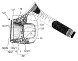
- the display body 12 may include a rotation support portion 122.
- the rotation support portion 122 is coupled to the housing portion 121 and is accommodated in the upper portion of the inside of the housing portion 121, and is rotatably supported on the rotation support piece 11121 of the wear portion 11. [ Lt; / RTI > In addition, the rotation support portion 122 can restrict the rotation angle of the display main body 12. [
- the rotation support portion 122 may include a rotation support body 1221, a rotation axis 1222, a rotation limiting member 1223, and an elastic member 1224.
- the rotation support body 1221 is installed in the housing part 121 of the display body 12 and has a predetermined accommodation space inside to accommodate a part of the wear part 11, that is, the rotation support piece 11121 have.
- a support structure in which a rotation shaft 1222 is provided at the center of the rotation support body 1221, and a receiving space for accommodating the rotation support piece 11121 can be formed on both sides of the center.
- the rotation shaft 1222 is formed in the shape of a pin having a circular shape in a cross section, and is rotatably supported by the rotation support body 1221 and a part of the wear portion 11 accommodated in the rotation support body 1221 (The rotation supporting piece 11121) so that the rotation supporting body 1221 and the wearing portion 11 can be rotatably connected.
- the rotation restricting member 1223 is coupled to the lower surface of the rotation support body 1221 and has one surface (the end surface of the rotation supporting piece 11121) of the wearing portion 11
- a plurality of engagement protrusions 12231 may be formed to allow a part of the wearable portion 11 of the display main body 12 to be hooked on the rotation body. The user rotates the display main body 12 or the wearing portion 11 upward or downward to engage the end portion of the rotation supporting piece 11121 with any one of the plurality of engagement protrusions 12231, 12 or the rotation angle of the wearing portion 11 can be adjusted.
- the user when the user wears the head-mounted display device 1, the user first rotates the wearing part 11 upward so that the rotation supporting piece 11121 is caught by the engaging step 12231, 11 are fixed to the display main body 12 in an inclined state by a predetermined angle. Next, after the wearer 11 is sloped and fixed, one side of the display body 12 is brought into close contact with the face of the user, and then the wearer 11 is rotated downward, . On the contrary, when the wearer 11 is first worn by the user, the user rotates the display body 12 upward so that the engagement protrusion 12231 is hooked on the rotation support piece 11121, And fixed at a predetermined angle with respect to the wearable portion 11.
- the user wears the wearer's head 11 on the head while the display body 12 is fixed in an inclined state, and then rotates the display body 12 downward so that one surface of the display body 12 faces the user's face . That is, the rotation limiting member 1223 fixes the display main body 12 or the wearing portion 11 in a tilted state by a predetermined angle according to the manner of wearing the user, The wearer 11 is prevented from falling down to the face of the user or the head of the user, thereby making it possible to wear comfortably and stably.
- the elastic member 1224 connects the rotation support body 1221 and a part of the wearer 11 to each other and elastically supports the rotation support body 1221.
- the elastic member 1224 may be formed in the form of a tension coil spring having a ring portion at both ends, and at least one or more of the elastic member 1224 may be installed inside the rotation support body 1221.
- the display main body 12 may include a stationary frame 123.
- the mounting frame 123 is accommodated in the housing portion 121 and is disposed at one opening of the housing portion 121, and is connected to the focus adjusting means 126, which will be described later, It can be linearly moved to one side or the other side along the penetration direction of the housing part 121.
- a display accommodating space 12a in which a video output means can be installed may be formed on one side of the stationary frame 123.
- the mounting frame 123 will be described in more detail.
- the mounting frame 123 may include a flange portion 1231, a display support portion 1232, a cushioning pad 1233, and a linearly movable member 1234.
- the beveled portion 1231 is provided around the front of the lens 125 to be described later, and can block light or foreign substances from entering the lens 125. More specifically, the flange portion 1231 is accommodated in the housing portion 121 and disposed in front of the face-receiving frame 124, and includes a hood 12311 surrounding the front of the lens 125, And an extension portion 12312 extending outward from the end portion and supported on the inner surface of the housing portion 121.
- the display support portion 1232 is disposed on the front surface of the bezel 1231 to define a display accommodation space 12a between the front surface of the bezel 1231 and one surface of the bezel 1231, (Not shown) provided in the camera body 12a. More specifically, the display support portion 1232 includes a first support portion 12321 that is provided on the front surface of the beep portion 1231 to support a vertical load applied to the video output means, and a second support portion 12321 that extends upward from the end of the first support portion 12321 And a second support portion 12322 for supporting the image output means supported by the first support portion 12321 in the direction of the lens 125.
- the second support portion 12322 may extend from the end of the first support portion 12321 toward the lens 125 side at a predetermined angle.
- the display support 1232 may further include an elastic plate (not shown) that can bend the second support portion 12322 outward by a predetermined angle using an elastic force.
- the width of the display accommodation space 12a can be adjusted to accommodate video output means of various thicknesses.
- the buffer pads 1233 are formed on one surface of the first support portion 12321 exposed to the display accommodation space 12a and one surface of the second support portion 12322 opposed to the front surface of the flange portion 1231, And can be brought into contact with video output means (not shown).
- the buffer pads 1233 may be formed of a rubber or silicone material having a predetermined frictional force with respect to the support object so as to absorb impact transmitted to the video output means and prevent the video output means from being separated.
- the linearly-moving member 1234 may be provided on the rear surface of the flange portion 1231 and extend by a predetermined length in one direction.
- a rack gear 12341 may be formed on one side of the linearly movable member 1234 along the longitudinal direction to be engaged with the pinion gear 1261 provided in the focus adjusting means 126. Therefore, when the pinion gear 1261 of the focus adjusting means 126 is rotated, the linearly movable member 1234 converts the rotational motion of the focus adjusting means 126 into a linear motion to linearly move the flange portion 1231 .
- the display body 12 may include a face receiving frame 124.
- the face receiving frame 124 may be accommodated in the housing part 121 and disposed at the other opening of the housing part 121. [ Inside the face receiving frame 124, a face receiving space 12b capable of receiving a part of the user's face may be formed.
- the face receiving frame 124 will be described in more detail.
- the face receiving frame 124 may include a face receiving body 1241, an awning pad 1242, and a socket portion 1243.
- the face receiving body 1241 may be provided on the inner side of the housing part 121 and may have coupling means (not shown) on the first face thereof to engage with the second biometric data obtaining part 30.
- the coupling means may be formed in the form of a velcro.
- the coupling means is not limited thereto, and may be modified into various forms within the scope of performing the same function.
- a face receiving space 12b capable of receiving the user's eyes and nose can be formed inside the face receiving body 1241.
- one side of the face receiving body 1241 in which the second biometric data obtaining unit 30 is installed is formed to have a structure recessed to a predetermined depth toward the front, so that the user's eyes and nose
- the face receiving space 12b can be formed.
- the face-receiving space 12b can be kept in a dark state by blocking light like a dark room.
- the shade pad 1242 may be installed in the face receiving body 1241 and disposed in the face receiving space 12b in which the user's nose is received. Therefore, when the head-mounted display device 1 is worn by the user, the awning pad 1242 is brought into close contact with the nose of the user located in the face receiving space 12b, And 12b.
- the awning pad 1242 may be formed in a plate shape having a predetermined thickness, with a plurality of cut-out grooves formed inside.
- the shade pad 1242 may be formed of rubber, silicone, stretchable flexible material or the like so that the shade pad 1242 can be completely brought into close contact with the user's nose through elasticity or stretchability when the nail pad 1242 is pressed against the user's nose.
- a means that can be coupled to the face receiving body 1241 may be provided on one side of the awning pad 1242.
- the socket portion 1243 may be provided in the face receiving body 1241 and electrically connected to the connector 33 provided in the second biometric data obtaining portion 30.
- the socket portion 1243 may be provided with a connection pin connectable to the pin portion 332 of the connector 33 and a removable magnetic body to the magnet 333 of the connector 33.
- the display body 12 may include a lens 125.
- a plurality of lenses 125 may be provided on the inner side of the face receiving frame 124 to be disposed opposite to each other along the width direction of the face receiving frame 124.
- the lens 125 may be provided around the lens 125 and may be provided with an annular fixture installed in the face receiving body 1241.
- the lens 125 may be formed in a spherical structure having a convex surface on both sides.
- the display body 12 may include focus adjustment means 126.
- the focusing means 126 may be received in the housing part 121 and coupled to the mounting frame 123.
- the focus adjusting means 126 may move the mounting frame 123 according to a user's operation so that the display accommodation space 12a is spaced from the lens 125 by a predetermined distance.
- the focus adjusting means 126 includes a pinion gear 1261 engaged with the rack gear 12341 of the linearly movable member 1234 and a power transmission gear 1262 transmitting rotational force to the pinion gear 1261 .
- the focus adjustment means 126 is rotatably mounted on the housing portion 121 so that one side is coupled to the power transmission gear 1262 and the other side is exposed to the outside of the housing portion 121, (1263). Accordingly, the user can transmit the rotational force to the power transmitting gear 1262 by turning the operating portion 1263 clockwise or counterclockwise.
- a plurality of power transmission gears 1262 may be provided.
- a gear protector for accommodating a plurality of power transmission gears 1262 therein may be installed in the hoop frame.
- the head-mounted display apparatus 1 includes a first biometric data acquiring section 20.
- the first biometric data acquiring unit 20 is installed inside the display unit 10 and photographs the face of the user accommodated in the display unit 10 when the user wears it, Which is at least a part of the first biometric data. More specifically, the first biometric data acquiring unit 20 photographs the face of the user accommodated in the display unit 10 and acquires, from the photographed image, movement of a line of sight, identification information through an iris region around the pupil, And the heart rate information due to the change in blood flow in the blood around the eye.
- the first biometric data obtaining unit 20 may include an infrared ray (IR) filter 21 and an angle adjusting unit 22.
- IR infrared ray
- the IR filter 21 may be disposed in the face receiving frame 124 and may be inclined at a predetermined angle with respect to the central axis direction of the lens 125.
- the IR filter 21 may have a plate-like structure having a predetermined thickness, and may be formed of a transparent material through which infrared rays can be transmitted.
- the angle adjusting portion 22 may be installed between the mounting frame 123 and the face receiving frame 124 at a predetermined angle.
- the angle adjusting portion 22 will be described in more detail.
- the angle adjusting portion 22 may include a receiving frame 221, an operating portion 222, and a rotating portion 223.
- the receiving frame 221 is provided in the housing part 121 and a predetermined receiving space can be formed inside the receiving frame 221 so as to accommodate the operating part 222 and the rotating part 223.
- a through hole may be formed in which a main shaft 2221 of the operating portion 222 and a driven shaft 2232 of the rotating portion 223 are rotatably provided.
- the operating part 222 is installed in the receiving frame 221 and is coupled to the rotating part 223 and can transmit rotational force to the rotating part 223 through the user's operation. More specifically, the operating portion 222 includes a main shaft 2221 rotatably coupled to the receiving frame 221, a main gear 2222 coupled to the main shaft 2221 and rotatable together with the main shaft 2221 . The operating portion 222 is coupled to the main shaft 2221 and is rotatable together with the main shaft 2221 and the main gear 2222. A portion of the operating portion 222 protrudes outside the housing portion 121, Means 2223 may be included.
- the rotation part 223 is installed in the receiving frame 221 and is coupled with the operation part 222 and can receive the rotational force from the operation part 222 and can be rotated clockwise or counterclockwise. More specifically, the rotating portion 223 may include a rotating body 2231 having a photographing portion 23 and an IR light source portion 24, which will be described later, and housed inside the receiving frame 221.
- the rotating portion 223 is provided with a driven shaft 2232 coupled to the rotating body 2231 and rotatably coupled to the receiving frame 221 and a driven shaft 2232 coupled to one side of the driven shaft 2232, And a driven gear 2233 which is engaged and rotated together with the rotating body 2231 and the driven shaft 2232 in accordance with the rotation of the driven gear 2222.
- the first biometric data acquiring unit 20 may include a photographing unit 23 and an IR light source unit 24.
- the photographing unit 23 is installed in the angle adjusting unit 22, and the angle can be adjusted according to the user's operation.
- the photographing section 23 can acquire the first biometric data, which is at least a part of the user's face, by photographing a specific part or the whole of the user's face accommodated in the face accommodation space 12b.
- the photographing section 23 may include a camera body including at least one lens on the inner side and an image sensor connected to the camera body.
- the photographing unit 23 located on the lower side of the display main body 12 is arranged in a state inclined at a predetermined angle with respect to the central axis of the lens 125 so as to photograph the face of the user accommodated in the face accommodating space 12b .
- the photographing section 23 can be applied as an infrared camera.
- the IR light source unit 24 is disposed around the photographing unit 23 and can emit infrared light that can pass through the IR filter 21 when the photographing unit 23 is driven. Also, the IR light source unit 24 may be installed in the angle adjusting unit 22, and the angle of the IR light source unit 24 may be adjusted according to a user's operation. Accordingly, the user can adjust the angle of the IR light source unit 24 to irradiate a specific portion or the whole of the user's face accommodated in the face receiving space 12b. For example, the IR light source unit 24 may be applied to an infrared LED, an infrared lamp, or the like.
- the head-mounted display device 1 includes a second biometric data acquiring section 30.
- the second biometric data acquiring unit 30 is detachably attachable to the display unit 10 and acquires second biometric data, which is a biometric signal of a user, in contact with the user's skin when the user wears the biometric data acquiring unit 30.
- second biometric data which is a biometric signal of a user
- the second biometric data obtaining unit 30 will be described in more detail with reference to Figs. 15 to 23. Fig.
- the second biometric data obtaining unit 30 may include a mask body 31.
- the mask body 31 may have a curved structure along the width direction (Y-axis direction) and the height direction (Z-axis direction).
- the mask body 31 may have a projection 311a for communicating the lens 125 provided on the display unit 10 with the eye of the user.
- the mask body 31 may be formed in a detachable structure with respect to the display unit 10.
- a coupling means 314 for fixing the mask body 31 to the display unit 10 may be provided on one side of the mask body 31 opposite to the display unit 10.
- the coupling means 314 is provided on the other surface of the mask body 31, which is opposed to one surface of the mask body 31 provided with the detection means 32 to be described later, and is provided along the edge portion of the mask body 31 And can be installed in a plurality of areas.
- the engaging means 40 may be formed in the form of a velcro.
- the coupling means 40 is not limited thereto, and may be modified into various forms within the scope of performing the same function.
- the mask body 31 may include a frame portion 311.
- the frame unit 311 may be formed in a structure in which the frame unit 311 is disposed opposite the forehead region of the user and the user's eye region when worn by the user, so as to surround the user's forehead region and the user's eye periphery region.
- a projection 311a on which a user's eye and a user's nose can be positioned may be formed inside the frame portion 311.
- the frame unit 311 will be described in more detail.
- the frame portion 311 may include a first support portion 3111 and a second support portion 3112.
- the first support portion 3111 may be disposed opposite the forehead portion of the user when the user wears it.
- a mounting recess 3111a may be formed at an inner center of the first supporting portion 3111 so that a connector 33 to be described later may be installed.
- the mounting recess 3111a may be formed in a predetermined depth along a direction (X-axis direction in FIG.
- a through hole 3111b may be formed in the mounting groove 3111a so that a part of the connector 33 provided in the mounting groove 3111a may be exposed to the outside of the frame portion 311.
- the mounting groove 3111a may further include a fastening hole for fastening fastening means (not shown) for fastening the connector 33 to the first supporting portion 3111.
- the second support portion 3112 extends from one side and the other end of the first support portion 3111 along the width direction of the mask main body 31 in the Y axis direction .
- extending curvedly to the lower side of the mask body 31 means extending from the end of the mask body 31 downward along the height direction (the Z-axis direction in FIG. 2) of the mask body 31 can do.
- the second support portion 3112 may include a first extension portion extending in a vertical direction from the end of the first support portion 3111 with respect to the drawing, such that the second support portion 3112 may be disposed opposite the temporal portion and the crotch portion of the user's face when worn by the user And a second extension section extending in the horizontal direction from an end of the first extension section.
- the user's eyes and the projection 311a can be formed on the inner side of the first support portion 3111 and the second support portion 3112 to receive the user's nose.
- the second supporting portion 3112 can be formed in a structure that can adjust the length along the height direction (Z-axis direction in FIG. 2) of the mask body 31.
- a length adjusting member (not shown) for guiding the movement of the second supporting portion 3112 and fixing the second supporting portion 3112 moved to a predetermined position is provided on the inner side of the first supporting portion 3111 and the second supporting portion 3112 May be provided. Accordingly, the user can stably support the display unit 10 by adjusting the length of the second support unit 3112 in accordance with the positions of the eyes and the nose of the user.
- the frame portion 311 may be formed of a plastic material or a carbon material having a predetermined strength against bending.
- the frame portion 311 may be formed with a plurality of through holes passing through the frame portion 311 so that the frame portion 311 can be made lighter.
- the frame part 311 is not limited to this, and can be applied to various materials.
- the mask body 31 may include a buffer portion 312.
- the buffering part 312 is installed on one surface of the frame part 311 facing the user's face and is supported on the face of the user when worn by the user to load the display part 10 It can be evenly distributed to the user's face.
- the buffer part 312 may be formed in the form of a FOAM of a PE material having a predetermined thickness.
- the buffering part 312 is not limited to this, and may be applied to a material such as a sponge, a gel (GEL), a latex or an air foam so as to perform the same function.
- the buffer part 312 may be disposed on one side of the frame part 311, and may be disposed along the edge area of the frame part 311.
- the mask body 31 may further include an elastic member 313.
- the elastic member 313 is formed of an elastic fabric material having elasticity, and surrounds the frame portion 311 and the buffer portion 312, and a sensing means 32 And can be elastically supported.
- a buffer space 313a may be formed between the buffer part 312 and the frame part 311 disposed in the edge area of the frame part 311.
- the elastic member 313 may be formed of a material having a higher modulus of elasticity than the buffering portion 312.
- the surface of the elastic member 313 may be formed of nylon, suede, or the like so as to minimize frictional force upon contact with the skin.
- the second biometric data acquiring section 30 may include the sensing means 32.
- the sensing means 32 is provided on one side of the mask body 31 facing the face of the user when the wearer wears it, and the elastic member 313 of the mask body 31 is elastic So that it can be brought into contact with the user's skin. Accordingly, the sensing means 32 can sense the second biometric data, which is the biometric signal of the user.
- the sensing means 32 is formed of a disk-shaped electrode made of a metal material or a thin-film electrode printed on a flexible substrate, and connected to the display unit 10 to sense a user's bio- can do.
- the sensing means 32 may be installed on one side of the mask body 31 through a press-fitting or adhesive method.
- the sensing means 32 may be further provided with an EMI shielding (electromagnetic shielding) process for shielding electromagnetic waves.
- the head-mounted display device 1 includes a buffer part 312 supported on one side of the mask body 31 to disperse the load of the display part 10 on the user's face, Since the elastic member 313 is formed of a material and is pressed out to the forehead region of the user, the elastic member 313 is stretched outward and is brought into close contact with the forehead of the user, so that the surface of the sensing means 32 contacting the skin can be stably secured. Also, the display unit 10 can be stably supported on the face of the user, so that the display unit 10 can be prevented from being detached from the face of the user due to the movement of the user.
- the sensing means 32 is elastically supported to minimize the pressure applied to the forehead of the user, thereby allowing marks on the user's skin to remain or minimizing the occurrence of pain.
- the sensing means 32 can be formed in a structure that can be brought into close contact with the forehead of the user by using its own elastic force.
- the sensing means 32 is installed in the mask body 31 and moves linearly in one direction when an external force is applied from the outside and is linearly moved in the other direction by an elastic force when the external force is released, As shown in FIG.
- the sensing means 32 formed of an elastic supporting structure will be described in more detail.
- the sensing means 32 may include a support ring 321, a guide housing 322, an electrode portion 323 and an elastic support member 324.
- the support ring 321 may be formed in a circular annular shape formed with a press-fit groove toward the inner center along the periphery, and may be installed in the mask body 31.
- the support ring 321 may be installed in the mask body 31 in a press-fitted manner.
- the guide housing 322 is fastened to the inside of the support ring 321 and a guide hole 322a may be formed along the center axis direction inside.
- a step for limiting the movement of the electrode part 323 may be formed in the guide housing 322.
- a screw thread that can be engaged with each other can be formed on the outer peripheral surface of the guide housing 322 and the inner peripheral surface of the support ring 321.
- the electrode unit 323 may be disposed inside the guide housing unit 322 and linearly movable along the guide hole 322a.
- One side and the other side of the electrode portion 323 may protrude outside the guide housing 322, respectively.
- the protruding piece may be formed on one side of the electrode unit 323 to be hooked on the step formed in the guide housing 322.
- the elastic support member 324 is installed inside the guide housing 322 and is formed in the form of a coil spring to elastically support the electrode portion 323.
- the sensing means 32 formed of an elastic support structure may be provided on the elastic member 313 of the mask body 31 or on the buffer portion 312 provided on one surface of the frame portion 311.
- the buffer unit 312 may be formed in a shape corresponding to one surface of the frame unit 311 so as to directly contact the user's skin. have.
- the mask body 31 may be formed in a structure in which the elastic member 313 is not provided.
- the sensing means 32 may be arranged to face the frontal region when the user wears it to sense the user's brain wave signal.
- the sensing means 32 may be disposed at a position opposite to the forehead portion of the wearer when the wearer wears it. That is, the sensing means 32 may be disposed at a position opposite to one surface of the first support portion 3111 positioned at the forehead portion of the user when the user wears the sensor.
- a plurality of sensing means 32 may be provided. More specifically, the plurality of sensing means 32 may comprise a ground, a reference, and measurement units (channel 1, channel 2).
- the ground and the reference may be arranged at positions corresponding to the center of the first support 3111 and spaced apart by a predetermined distance along the height direction (Z-axis direction) of the mask body 31 .
- the measurement units channel1 and channel2 are disposed along the width direction (Y axis direction) of the mask body 31 with respect to the center of the first support portion 3111 where the ground and the reference are located. 1 support portions 3111 of the first embodiment. For example, a plurality of measurement units (channel 1, channel 2) arranged opposite to each other may be provided.
- the sensing means 32 may be disposed opposite to the temporal portion and the crotch portion of the wearer to wear the user's body to sense the user's vital signs.
- the sensing means 32 may be disposed at a position opposite to one surface of the second supporting portion 3112 so as to face the temporal portion and the navel portion of the user when the user wears it.
- the sensing means 32 in contact with the temporal region and the crotch region of the user may include a user's heart rate signal (PPG), electrocardiogram (ECG) signal, electromyography signal (EMG) At least one of them can be detected.
- PPG heart rate signal
- ECG electrocardiogram
- EMG electromyography signal
- the sensing means 32 may be electrically connected to other sensing means in contact with a body part other than the user's face. Accordingly, the bio-signals other than the bio-signals described above can be additionally detected.
- the sensing means 32 connected to the other sensing means may further sense a bioelectrical impedance analysis (BIA), a galvanic skin response (GSR), and the like.
- BIOA bioelectrical impedance analysis
- GSR galvanic skin response
- the sensing means 32 may be installed in the mask body 31 so as to be adjustable in position.
- the mask body 31 may be provided with a movement adjusting member 325 for guiding the movement of the sensing means 32 according to a user's operation.
- the movement adjusting member 325 is formed in a ring shape and a guide hole 325a for guiding the movement of the sensing means 32 may be formed inside the movement adjusting member 325.
- the shape of the guide hole 325a is curved along the horizontal direction, but the shape of the guide hole 325a is not limited thereto, and the shape of the guide hole 325a is not limited to the shape of the sensing means 32 along the horizontal or vertical direction.
- the present invention is not limited thereto.
- the second biometric data acquiring section 30 may include a connector 33.
- the connector 33 is connected to the socket unit 1243 of the display unit 10 and is connected to the sensing unit 32, And transmit at least one second biometric data sensed by the means 32 to the control means (not shown).
- the connector 33 can be coupled to the socket portion 1243 of the display unit 10 using magnetic force.
- the connector 33 includes a connector housing 331 provided to the mask body 31, a fin portion 332 electrically connected to the sensing means 32 and disposed at an inner central portion of the connector housing 331, And a magnet 333 disposed around the magnet 332.
- the connector 33 can be coupled to the socket portion 1243 by a magnetic force only when the connector 33 is aligned with the center of the socket portion 1243.
- the connector 33 and the socket portion 1243 can be more stably fixed by the magnetic force.
- a virtual reality image is provided to a user, but also biometric data is obtained from a face of a user who is checking a virtual reality image, It is possible to develop contents including various experience elements, and further, it is possible to improve the user's experience satisfaction by providing contents suitable for the current state of the user in real time.
- the display body 12 is coupled to the wearable portion 11 in a rotatable manner and the wearable portion 11 is formed in the form of an annular structure that can be worn by one hand, It is possible to freely secure the view of the user, thereby increasing convenience.
- the display body 12 can be stably fixed to the front face of the user through the annular wear part 11 formed in the form of a structure, and even when a somewhat violent movement is generated from the user during the experience, It is possible to prevent the user 12 from deviating from the face of the user.
- the mask body 31 supported on the face of the user can be detachably attached to the display main body 12, it is easy to replace and the service life of the equipment can be prolonged, and the cost can be further reduced.
- the head-mounted display device can be used in industrial fields such as games, education, defense, medical care, etc., in which spatial and temporal experiences similar to actual ones can be realized.
Abstract
본 발명의 실시예에 따른 헤드 마운트 디스플레이 장치는 사용자의 착용 시 사용자의 얼굴에 대향 배치되고, 일 측에 설치되는 영상출력수단을 통하여 사용자에게 가상현실 영상을 제공하는 디스플레이부; 디스플레이부에 설치되고, 사용자의 착용 시 디스플레이부에 수용된 사용자의 얼굴을 촬영하여 제1 생체 데이터를 획득하는 제1 생체 데이터 획득부; 및 디스플레이부에 설치되고, 사용자의 착용 시 사용자의 피부에 접촉되어 제2 생체 데이터를 획득하는 제2 생체 데이터 획득부;를 포함하는 것을 특징으로 한다. 본 발명의 실시예에 따르면, 사용자에게 가상현실 영상을 제공함은 물론, 가상현실 영상을 확인 중인 사용자의 얼굴로부터 생체 데이터를 획득함으로써, 가상현실 영상을 확인 중인 사용자의 인지 및 감정 상태를 실시간 확인 가능하고, 이를 통해 다양한 체험요소를 포함하는 콘텐츠를 개발 가능하며, 나아가 사용자의 현재 상태에 적합한 콘텐츠를 실시간 제공하여 사용자의 체험 만족도를 향상시킬 수 있다.
Description
본 발명은 헤드 마운트 디스플레이 장치에 관한 것으로, 더욱 상세하게는 착용이 용이하고, 착용 시 사용자의 생체 데이터를 측정할 수 있는 헤드 마운트 디스플레이 장치에 관한 것이다.
일반적으로 헤드 마운트 디스플레이 장치(HMD: Head-Mounted Display)는, 사용자의 머리에 착용 가능한 구조로 형성되어 사용자가 실제와 유사한 공간적, 시간적 체험이 가능할 수 있도록 사용자에게 가상현실(VR: Virtual Reality) 영상을 제공하는 디스플레이 장치이다.
이와 같은 헤드 마운트 디스플레이 장치는, 사용자의 눈 부위에 착용 가능하도록 고글(goggle) 형태로 형성되는 본체와, 본체에 연결되어 본체를 사용자의 머리에 고정시킬 수 있도록 밴드 형태로 형성되는 착용부로 구성된다. 여기서, 본체에는 가상현실 영상을 출력하는 수단으로서, 스마트폰 등과 같은 휴대용 단말 장치가 설치되거나, 모니터 등과 같이 PC 등에 연결되는 디스플레이 장치가 설치된다.
그러나, 종래의 헤드 마운트 디스플레이 장치는, 단순히 사용자가 휴대용 단말장치에 설치된 영상출력수단으로부터 출력되는 영상을 시각적으로만 확인할 수 있도록 제작됨에 따라, 활용도가 낮고, 영상출력수단에 제공되는 콘텐츠의 종류가 지극히 한정적인 문제점이 있었다.
또한, 종래의 헤드 마운트 디스플레이 장치는 본체와 착용부가 일체로 형성되거나, 착용부가 머리 전체를 감싸는 고무재질의 밴드 형태로 형성됨에 따라, 착용이 용이하지 않고, 사용자가 일시적으로 가상체험을 중단하고 시야를 확보하기 위해서는 반드시 장비를 머리로부터 탈거해야만 하는 불편함이 있었다.
아울러, 종래의 헤드 마운트 디스플레이 장치의 본체는 상용자의 머리를 감싸는 고무재질의 밴드를 통해 지지됨에 따라, 사용자의 얼굴에 안정적으로 고정되지 못하고, 이로 인해 사용자의 체험도중 사용자의 얼굴로부터 이탈되는 문제점이 있었다.
또한, 종래의 헤드 마운트 디스플레이 장치는 본체의 일면에 사용자의 착용 시 사용자의 얼굴에 밀착되는 완충재가 일체로 구비됨에 따라, 완충재가 변형 또는 파손될 경우, 교체가 불가능한 문제점이 있었다. 따라서, 사용자는 완충재가 변형 또는 파손될 겨우 헤드 마운트 디스플레이 장치 전체를 교체하거나, 완충재가 변형 또는 파손된 상태로 헤드 마운트 디스플레이 장치를 사용해야만 하는 문제점이 있었다.
본 발명은 상기와 같은 문제점을 해결하기 위해 안출된 것으로서, 본 발명의 목적은 착용이 용이하고, 착용 시 사용자의 생체 데이터를 측정하여 사용자의 신체적, 인지적, 감정적 변화를 감지할 수 있는 헤드 마운트 디스플레이 장치를 제공하는 것이다.
본 발명의 과제는 이상에서 언급한 과제들로 제한되지 않으며, 언급되지 않은 또 다른 과제들은 아래의 기재로부터 당업자에게 명확하게 이해될 수 있을 것이다.
상기 과제를 해결하기 위한 본 발명의 실시예에 따른 헤드 마운트 디스플레이 장치는 사용자의 착용 시 사용자의 얼굴에 대향 배치되고, 일 측에 설치되는 영상출력수단을 통하여 사용자에게 가상현실 영상을 제공하는 디스플레이부; 상기 디스플레이부에 설치되고, 사용자의 착용 시 상기 디스플레이부에 수용된 사용자의 얼굴을 촬영하여 제1 생체 데이터를 획득하는 제1 생체 데이터 획득부; 및 상기 디스플레이부에 설치되고, 사용자의 착용 시 사용자의 피부에 접촉되어 제2 생체 데이터를 획득하는 제2 생체 데이터 획득부;를 포함하는 것을 특징으로 한다.
상기 디스플레이부는, 사용자의 머리에 착용 가능한 착용부; 및 상기 착용부에 회전 가능하게 결합되어 사용자의 조작에 따라 사용자의 얼굴에 선택적으로 대향 배치되고, 일 측에 사용자 얼굴의 일부를 수용할 수 있는 안면 수용공간과, 타 측에 상기 영상출력수단을 수용할 수 있는 디스플레이 수용공간이 형성되는 디스플레이 본체;를 포함할 수 있다.
상기 착용부는, 내측에 사용자의 머리를 수용할 수 있는 머리수용공간이 형성되어 사용자의 착용 시 사용자의 머리 둘레에 배치되는 밴드부, 및 상기 밴드부로부터 연장되어 상기 회전 지지부에 회전 가능하게 결합되는 밴드 지지부를 포함하는 착용본체; 상기 착용본체에 설치되고, 사용자의 조작에 따라 상기 착용본체의 내경을 조절 가능한 내경 조절수단; 및 상기 밴드부의 내면에 설치되고, 사용자의 착용 시 사용자의 머리에 지지되는 완충부;를 포함할 수 있다.
상기 내경 조절수단은, 상기 밴드부에 결합되는 지지판 및 상기 지지판의 중앙부에 회전 가능하게 설치되고 일 측에 피니언 기어를 구비하는 회전조절부재를 포함하는 조절부; 상기 밴드부의 내면에 설치되어 상기 조절부에 대향 배치되고, 일 면에 길이방향을 따라 가이드레일이 형성되는 안내판; 및 상기 가이드레일에 수용되어 일 측에 상기 피니언 기어에 치합되는 랙기어를 구비하고, 타 측에 상기 밴드부에 결합되는 결합수단을 구비하며, 상기 회전조절부재의 회전 시 일 측 또는 타 측으로 이동하여 상기 밴드부의 내경을 조절하는 이동부재;를 포함할 수 있다.
상기 디스플레이 본체는, 내부가 일 방향으로 관통되어 일 측 및 타 측에 개구부가 형성되는 하우징부; 상기 하우징부에 수용되어 상기 착용부에 회전 가능하게 결합되고, 상기 디스플레이 본체의 회전 각도를 제한하는 회전 지지부; 상기 하우징부의 일 측 개구부에 배치되고, 일 측에 상기 디스플레이수용공간이 형성되며, 상기 하우징부의 관통방향을 따라 선형이동 가능한 거치 프레임; 상기 하우징부의 타 측 개구부에 배치되고, 내측에 상기 안면 수용공간이 형성되는 안면 수용 프레임; 상기 안면 수용 프레임에 설치되는 렌즈; 및 상기 거치 프레임에 결합되고, 사용자의 조작에 따라 상기 거치 프레임을 이동시켜 상기 디스플레이 수용공간을 상기 렌즈로부터 미리 설정된 거리만큼 이격시키는 초점 조절수단;을 포함할 수 있다.
상기 회전 지지부는, 상기 디스플레이 본체에 설치되고, 내측에 상기 착용부의 일부를 수용할 수 있는 회전 지지본체; 상기 회전 지지본체와 상기 회전 지지본체에 수용된 상기 착용부의 일부를 관통하여 상기 회전 지지본체와 상기 착용부를 회전 가능하게 연결하는 회전축; 상기 회전 지지본체에 결합되고, 상기 착용부의 일부에 대향하는 일면에 상기 디스플레이 본체의 회전 시 상기 착용부의 일부가 걸려 지지될 수 있도록 복수개의 걸림턱이 형성되는 회전 제한부재; 및 상기 회전 지지본체와 상기 착용부의 일부를 서로 연결하고, 상기 회전 지지본체를 탄성적으로 지지하는 탄성부재;를 포함할 수 있다.
상기 거치 프레임은, 상기 하우징부에 수용되어 상기 안면 수용 프레임의 전방에 배치되고 상기 렌즈의 둘레를 감싸는 후드, 및 상기 후드의 단부로부터 외측으로 연장되어 상기 하우징부의 내면에 지지되는 확장부를 포함하는 차양부; 상기 차양부의 전면에 설치되어 상기 영상출력수단에 가해지는 수직하중을 지지하는 제1 지지부, 및 상기 제1 지지부의 단부로부터 상향 연장되어 상기 제1 지지부에 지지된 상기 영상출력수단을 상기 렌즈방향으로 지지하는 제2 지지부를 포함하는 디스플레이 지지부; 상기 차양부, 상기 제1 지지부 및 상기 제2 지지부에 설치되어 상기 영상출력수단에 접촉되는 완충패드; 및 상기 차양부에 설치되고, 일면에 길이방향을 따라 랙기어가 형성되어 상기 초점 조절수단에 결합되며, 상기 초점조절수단의 회전운동을 직선운동으로 변환하여 상기 차양부를 직선 이동시키는 직선이동부재;를 포함할 수 있다.
상기 안면 수용 프레임은, 일면에 상기 제2 생체 데이터 획득부와 결합 가능한 결합수단을 구비하고, 내측에 사용자의 눈 및 코를 수용할 수 있는 상기 안면 수용공간이 형성되는 안면 수용본체; 상기 안면 수용본체에 설치되고, 사용자의 착용 시 사용자의 코에 밀착되어 상기 안면 수용공간으로 유입되는 빛을 차단하는 차양패드; 및 상기 안면 수용본체에 설치되어 상기 제2 생체 데이터 획득부와 전기적으로 연결되는 소켓부;를 포함할 수 있다.
상기 초점 조절수단은, 상기 직선이동부재의 랙기어에 치합되는 피니언 기어; 상기 피니언 기어에 회전력을 전달하는 동력전달 기어; 및 상기 동력전달 기어에 결합되어 일부가 상기 하우징부의 외측으로 노출되고, 사용자의 조작에 따라 상기 동력전달 기어에 회전력을 전달하는 조작부;를 포함할 수 있다.
상기 제1 생체 데이터 획득부는, 상기 안면 수용 프레임에 설치되고, 상기 렌즈의 중심축 방향에 대하여 미리 설정된 각도로 경사지게 배치되는 IR 필터; 상기 거치 프레임과 상기 안면 수용 프레임 사이에 미리 설정된 각도로 회전 가능하게 설치되는 각도 조절부; 상기 각도 조절부에 설치되어, 사용자 얼굴의 적어도 일부인 상기 제1 생체 데이터를 촬영 가능한 촬영부; 및 상기 각도 조절부에 설치되고, 상기 촬영부의 둘레에 배치되어 광을 발산하는 IR 광원부;를 포함할 수 있다.
상기 각도 조절부는, 상기 하우징부에 설치되고, 내측에 수용공간을 형성하는 수용 프레임; 상기 수용 프레임에 회전 가능하게 결합되는 주동축, 상기 주동축에 결합되어 상기 주동축과 함께 회전 가능한 주동기어, 및 상기 주동축에 결합되어 상기 주동축 및 상기 주동기어와 함께 회전 가능하고, 일부가 상기 하우징부의 외측으로 돌출되어 사용자의 조작이 가능한 조작수단을 포함하는 조작부; 및 내측에 상기 촬영부 및 상기 IR 광원부가 설치되고, 상기 수용 프레임의 내부에 수용되는 회전체, 상기 회전체에 결합되어 상기 수용 프레임에 회전 가능하게 결합되는 종동축, 및 상기 종동축의 일 측에 결합되어 상기 주동기어에 치합되고, 상기 주동기어의 회전에 따라 상기 회전체 및 상기 종동축과 함께 회전되는 종동기어를 포함하는 회전부;를 포함할 수 있다.
상기 제2 생체 데이터 획득부는, 상기 디스플레이부에 대향하는 일면에 결합수단을 구비하여 상기 디스플레이부에 탈부착 가능한 마스크 본체; 상기 마스크 본체에 설치되고, 사용자의 착용 시 사용자의 피부에 접촉되어 사용자의 생체신호인 상기 제2 생체 데이터를 감지하는 감지수단; 및 상기 마스크 본체에 설치되어 상기 감지수단과 전기적으로 연결되고, 상기 디스플레이부에 구비된 소켓부에 연결되어 상기 감지수단으로부터 감지된 상기 제2 생체 데이터를 전송하는 커넥터;를 포함할 수 있다.
본 발명의 실시예에 따르면, 사용자에게 가상현실 영상을 제공함은 물론, 가상현실 영상을 확인 중인 사용자의 얼굴로부터 생체 데이터를 획득함으로써, 가상현실 영상을 확인 중인 사용자의 인지 및 감정 상태를 실시간 확인 가능하고, 이를 통해 다양한 체험요소를 포함하는 콘텐츠를 개발 가능하며, 나아가 사용자의 현재 상태에 적합한 콘텐츠를 실시간 제공하여 사용자의 체험 만족도를 향상시킬 수 있다.
또한, 디스플레이 본체가 착용부에 회전 가능한 구조로 결합되고, 착용부는 한 손으로 착용할 수 있는 고리형상의 구조물 형태로 형성됨에 따라, 착용이 용이하고, 필요에 따라 자유롭게 사용자의 시야를 확보 가능하여 편의성이 증대될 수 있다.
또한, 구조물 형태로 형성된 고리형상의 착용부를 통하여, 디스플레이 본체를 사용자의 얼굴 전면에 안정적으로 고정시킬 수 있고, 나아가 체험 중 사용자로부터 다소 과격한 움직임이 발생될 경우에도 디스플레이 본체가 사용자의 얼굴로부터 이탈되는 것을 예방할 수 있다.
또한, 사용자의 얼굴에 지지되는 마스크 본체를 디스플레이 본체에 탈부착 가능한 구조로 형성함으로써, 교체가 용이하여 장비의 사용수명을 연장시킬 수 있고, 나아가 비용을 절감할 수 있다.
도 1은 본 발명의 실시예에 따른 헤드 마운트 디스플레이 장치의 전면 구조를 나타낸 사시도이다.
도 2는 본 발명의 실시예에 따른 헤드 마운트 디스플레이 장치의 후면 구조를 나타낸 사시도이다.
도 3은 본 발명의 실시예에 따른 헤드 마운트 디스플레이 장치를 나타낸 정면도이다.
도 4는 도 3의 IV-IV 선을 따라 절개한 단면도이다.
도 5는 본 발명의 실시예에 따른 헤드 마운트 디스플레이 장치를 나타낸 측면도이다.
도 6은 도 5의 VI-VI 선을 따라 절개한 단면도이다.
도 7은 본 발명의 실시예에 따른 헤드 마운트 디스플레이 장치에서 안면 수용 프레임이 제거된 디스플레이 본체를 나타낸 배면도이다.
도 8은 도 3의 VIII-VIII 선을 따라 절개한 단면도이다.
도 9는 도 3의 IX-IX 선을 따라 절개한 단면도이다.
도 10은 도 9의 "A"부분을 확대한 확대도이다.
도 11은 본 발명의 실시예에 따른 헤드 마운트 디스플레이 장치에서 하우징부가 제거된 디스플레이 본체를 나타낸 평면도이다.
도 12는 본 발명의 실시예에 따른 헤드 마운트 디스플레이 장치의 디스플레이 본체를 나타낸 배면도이다.
도 13은 본 발명의 실시예에 따른 헤드 마운트 디스플레이 장치의 제1 생체 데이터 획득부를 나타낸 정면도이다.
도 14는 본 발명의 실시예에 따른 헤드 마운트 디스플레이 장치에서 제1 생체 데이터 획득부의 후면 구조를 나타낸 사시도이다.
도 15는 본 발명의 실시예에 따른 헤드 마운트 디스플레이 장치에서 제2 생체 데이터 획득부의 프레임부를 나타낸 정면도이다.
도 16은 본 발명의 실시예에 따른 헤드 마운트 디스플레이 장치의 제2 생체 데이터 획득부를 나타낸 종단면도이다.
도 17은 본 발명의 실시예에 따른 헤드 마운트 디스플레이 장치의 제2 생체 데이터 획득부의 착용과정을 개략적으로 나타낸 도면이다.
도 18은 본 발명의 실시예에 따른 헤드 마운트 디스플레이 장치의 제2 생체 데이터 획득부의 프레임부에 완충부가 설치된 상태를 나타낸 정면도이다.
도 19는 본 발명의 실시예에 따른 헤드 마운트 디스플레이 장치의 제2 생체 데이터 획득부에서 감지수단의 변형된 실시예를 개략적으로 나타낸 단면도이다.
도 20은 본 발명의 실시예에 따른 헤드 마운트 디스플레이 장치의 제2 생체 데이터 획득부를 나타낸 정면도이다.
도 21은 본 발명의 실시예에 따른 헤드 마운트 디스플레이 장치에서 제2 생체 데이터 획득부에 구비된 감지수단의 변형된 실시예를 개략적으로 나타낸 도면이다.
도 22는 본 발명의 실시예에 따른 헤드 마운트 디스플레이 장치의 제2 생체 데이터 획득부의 커넥터를 개략적으로 나타낸 단면도이다.
도 23은 본 발명의 실시예에 따른 헤드 마운트 디스플레이 장치의 제2 생체 데이터 획득부를 나타낸 배면도이다.
이하에서는 첨부된 도면을 참조하여 다양한 실시예를 보다 상세하게 설명한다. 본 명세서에 기재된 실시예는 다양하게 변형될 수 있다. 특정한 실시예가 도면에서 묘사되고 상세한 설명에서 자세하게 설명될 수 있다. 그러나, 첨부된 도면에 개시된 특정한 실시예는 다양한 실시예를 쉽게 이해하도록 하기 위한 것일 뿐이다. 따라서, 첨부된 도면에 개시된 특정 실시예에 의해 기술적 사상이 제한되는 것은 아니며, 발명의 사상 및 기술 범위에 포함되는 모든 균등물 또는 대체물을 포함하는 것으로 이해되어야 한다.
제1, 제2 등과 같이 서수를 포함하는 용어는 다양한 구성요소들을 설명하는데 사용될 수 있지만, 이러한 구성요소들은 상술한 용어에 의해 한정되지는 않는다. 상술한 용어는 하나의 구성요소를 다른 구성요소로부터 구별하는 목적으로만 사용된다.
본 명세서에서, "포함한다" 또는 "가지다" 등의 용어는 명세서상에 기재된 특징, 숫자, 단계, 동작, 구성요소, 부품 또는 이들을 조합한 것이 존재함을 지정하려는 것이지, 하나 또는 그 이상의 다른 특징들이나 숫자, 단계, 동작, 구성요소, 부품 또는 이들을 조합한 것들의 존재 또는 부가 가능성을 미리 배제하지 않는 것으로 이해되어야 한다. 어떤 구성요소가 다른 구성요소에 "연결되어" 있다거나 "접속되어" 있다고 언급된 때에는, 그 다른 구성요소에 직접적으로 연결되어 있거나 또는 접속되어 있을 수도 있지만, 중간에 다른 구성요소가 존재할 수도 있다고 이해되어야 할 것이다. 반면에, 어떤 구성요소가 다른 구성요소에 "직접 연결되어" 있다거나 "직접 접속되어" 있다고 언급된 때에는, 중간에 다른 구성요소가 존재하지 않는 것으로 이해되어야 할 것이다.
한편, 본 명세서에서 사용되는 구성요소에 대한 "모듈" 또는 "부"는 적어도 하나의 기능 또는 동작을 수행한다. 그리고, "모듈" 또는 "부"는 하드웨어, 소프트웨어 또는 하드웨어와 소프트웨어의 조합에 의해 기능 또는 동작을 수행할 수 있다. 또한, 특정 하드웨어에서 수행되어야 하거나 적어도 하나의 프로세서에서 수행되는 "모듈" 또는 "부"를 제외한 복수의 "모듈들" 또는 복수의 "부들"은 적어도 하나의 모듈로 통합될 수도 있다. 단수의 표현은 문맥상 명백하게 다르게 뜻하지 않는 한, 복수의 표현을 포함한다.
그 밖에도, 본 발명을 설명함에 있어서, 관련된 공지 기능 혹은 구성에 대한 구체적인 설명이 본 발명의 요지를 불필요하게 흐릴 수 있다고 판단되는 경우, 그에 대한 상세한 설명은 축약하거나 생략한다.
도 1 및 도 2를 참조하면, 본 발명의 실시예에 따른 헤드 마운트 디스플레이 장치(1)(이하 '헤드 마운트 디스플레이 장치(1)'라 함)는 사용자의 머리에 장착되어 사용자가 실제와 유사한 공간적, 시간적 체험이 가능할 수 있도록 사용자에게 가상현실(VR: Virtual Reality) 영상을 제공함과 동시에, 사용자의 생체 데이터를 측정하여 가상체험을 진행 중인 사용자의 신체적, 인지적, 감정적 변화를 감지할 수 있는 복합 가상 체험 장치로서, 디스플레이부(10)를 포함한다.
디스플레이부(10)는 사용자의 머리에 착용 가능한 구조로 형성되고, 사용자의 착용 시 사용자가 가상현실 영상을 확인할 수 있도록 일면이 사용자의 얼굴에 대향 배치된다. 여기서, 디스플레이부(10)의 일 측에는 사용자에게 가상현실 영상을 제공하는 영상출력수단(미도시)이 설치된다. 예컨대, 영상출력수단은 스마트폰, 태블릿 PC 등과 같은 휴대용 단말장치 또는 PC에 연결되어 PC로부터 제공되는 영상을 출력할 수 있는 휴대용 모니터 등으로 적용될 수 있다.
도 3 내지 도 12를 참조하여, 디스플레이부(10)에 대하여 더 자세히 설명한다.
디스플레이부(10)는 착용부(11)를 포함할 수 있다.
도 3을 참조하면, 착용부(11)는 사용자의 머리에 착용 가능한 구조로 형성될 수 있다. 더 자세하게는, 착용부(11)는 사용자의 착용 시 사용자의 머리 둘레를 감쌀 수 있도록 고리형의 밴드 구조로 형성될 수 있다.
도 4 및 도 5를 참조하면, 착용부(11)는 착용본체(111)와, 내경 조절수단(112)을 포함할 수 있다.
착용본체(111)는 일 부분이 절개된 원형 또는 타원형의 고리형상으로 형성되어 내측에 사용자의 머리를 수용할 수 있는 머리수용공간(1111a)이 형성되고, 사용자의 착용 시 사용자의 머리 둘레에 배치되는 밴드부(1111)를 포함할 수 있다. 그리고, 착용본체(111)는 밴드부(1111)의 일 측 단부로부터 일 방향으로 연장되어 후술할 디스플레이 본체(12)에 회전 가능하게 결합되는 밴드 지지부(1112)를 포함할 수 있다. 여기서, 밴드 지지부(1112)의 일 측에는 밴드 지지부(1112)의 내면으로부터 외측으로 돌출되어 디스플레이 본체(12)에 수용되고, 후술할 디스플레이 본체(12)의 회전 지지부(122)에 회전 가능한 구조로 결합되는 복수개의 회전 지지편(11121)이 형성될 수 있다. 예컨대, 착용부(11)는 소정의 탄성력을 가지는 플라스틱 소재로 형성되며, 착용부(11)의 내면에는 착용부(11)의 강성을 보완하기 위하여 착용부(11)의 내면을 따라 연속 배치되는 보강수단이 형성될 수 있다.
내경 조절수단(112)은 밴드부(1111)의 절개된 부위에 설치되어 절개된 부위로 인하여 분리된 밴드부(1111)의 양 단부를 서로 연결하고, 사용자의 조작에 따라 분리된 밴드부(1111)의 양 단부를 일 측 또는 타 측으로 이동시켜 착용본체(111)의 내경을 조절 할 수 있다.
도 4 및 도 6을 참조하여 내경 조절수단(112)에 대하여 더 자세히 설명한다.
내경 조절수단(112)은 조절부(1121)를 포함할 수 있다.
조절부(1121)는 밴드부(1111)의 분리된 양 단부 사이에 배치되고, 밴드부(1111)에 결합되어 밴드부(1111)의 분리된 양 단부를 서로 연결하는 지지판(11211)을 포함할 수 있다. 예컨대, 지지판(11211)은 밴드부(1111)의 형상과 연계될 수 있도록 밴드부(1111)의 내면에 대응되는 호(弧) 형상으로 형성되고, 일 측에 후크 등과 같은 체결수단을 구비하여 밴드부(1111)에 결합될 수 있다. 그리고, 조절부(1121)는 지지판(11211)의 중앙부에 회전 가능하게 설치되는 회전조절부재(11212)를 포함할 수 있다. 회전조절부재(11212)는 지지판(11211)의 중앙부에 회전 가능하게 설치될 수 있다. 그리고, 회전조절부재(11212)는 밴드부(1111)의 외측에 배치되는 파지수단 및 밴드부(1111)의 내측에 배치되는 피니언 기어(11212a)를 포함할 수 있다.
또한, 내경 조절수단(112)은 안내판(1122)을 포함할 수 있다.
안내판(1122)은 밴드부(1111)의 내면에 설치되어 조절부(1121)의 지지판(11211)에 대향 배치되고, 밴드부(1111)의 내면을 지지할 수 있도록 밴드부(1111)의 내면에 대응되는 호 형상으로 형성될 수 있다. 그리고, 밴드부(1111)의 내면에 접하는 안내판(1122)의 일면에는 후술할 이동부재(1123)가 설치될 수 있도록 안내판(1122)의 길이방향을 따라 가이드레일(11221)이 형성될 수 있다. 예컨대, 가이드레일(11221)은 도 6을 기준으로 수직방향을 따라 안내판(1122)에 복수개로 형성될 수 있다. 그리고, 안내판(1122)은 일 측에 후크 등과 같은 체결수단을 구비하여 밴드부(1111)에 결합될 수 있다.
또한, 내경 조절수단(112)은 이동부재(1123)를 포함할 수 있다.
이동부재(1123)는 가이드레일(11221)에 수용되어 안내판(1122)의 내면을 따라 이동 가능하도록 안내판(1122)의 내면에 대응되는 호 형상으로 형성될 수 있다. 그리고, 이동부재(1123)의 일 측에는 회전조절부재(11212)의 피니언 기어(11212a)에 치합되는 랙기어(11231)가 형성되고, 이동부재(1123)의 타 측에는 밴드부(1111)에 결합되는 결합수단이 형성될 수 있다. 따라서, 이동부재(1123)는 회전조절부재(11212)의 회전 시, 안내판(1122)의 내면을 따라 일 측 또는 타 측으로 이동하여 분리된 밴드부(1111)의 양 단부를 회전조절부재(11212)에 인접하도록 이동시키거나, 회전조절부재(11212)로부터 멀어지도록 이동시켜, 밴드부(1111)의 내경을 조절할 수 있다.
또한, 착용부(11)는 완충부(113)를 더 포함할 수 있다.
도 4를 참조하면, 완충부(113)는 밴드부(1111)의 내면에 설치되고, 사용자의 착용 시 사용자의 머리에 지지될 수 있다. 더 자세하게는, 완충부(113)는 밴드부(1111)의 내면에 탈부착 가능한 설치판, 설치판의 일면에 부착되는 완충재, 그리고 완충물의 외면에 설치되어 사용자의 착용 시 사용자의 피부에 접촉되는 외피를 포함할 수 있다. 예컨대, 설치판은 밴드부(1111)의 내면에 대응되는 형상으로 형성되고, 설치판의 일면에는 밴드부(1111)에 체결되는 체결수단이 구비될 수 있다. 그리고, 완충재는 소정의 두께를 가지는 스펀지, 라텍스 등의 소재로 형성되고, 외피는 직물, 가죽, 나일론 등의 소재로 형성될 수 있다. 또한, 완충부(113)는 밴드부(1111)의 내면에 복수개로 설치될 수 있다. 예컨대, 복수개의 완충부(113)는 사용자의 착용 시 사용자의 머리 전방 및 사용자의 머리 후방에 배치될 수 있도록 밴드부(1111)의 내면에 서로 대향되는 위치에 설치될 수 있다.
또한, 디스플레이부(10)는 디스플레이 본체(12)를 포함할 수 있다.
도 4를 참조하면, 디스플레이 본체(12)는 착용부(11)에 회전 가능하게 결합되고, 사용자의 조작에 따라 사용자의 얼굴에 선택적으로 대향 배치될 수 있다. 그리고, 디스플레이 본체(12)의 일 측에는 사용자 얼굴의 일부를 수용할 수 있는 안면 수용공간(12b)이 형성되고, 디스플레이 본체(12)의 타 측에는 영상출력수단을 수용할 수 있는 디스플레이 수용공간(12a)이 형성될 수 있다.
디스플레이 본체(12)에 대하여 더 자세히 설명한다.
디스플레이 본체(12)는 하우징부(121)를 포함할 수 있다.
도 7 및 도 8을 참조하면, 하우징부(121)는 일 방향으로 관통되어 일 측 및 타 측에 개구부가 형성된 관형의 구조로 형성되어 내부에 후술할 회전 지지부(122), 거치 프레임(123), 안면 수용 프레임(124), 초점 조절수단(126) 및 제1 생체 데이터 획득부(20)를 수용할 수 있다. 그리고, 하우징부(121)의 일 측 측면에는 디스플레이 본체(12)와 연결되는 케이블(미도시)을 감싸 지지할 수 있도록 외측으로 돌출되어 내측에 케이블을 수용 가능한 케이블 보호부(1211)가 형성될 수 있다. 또한, 케이블 보호부(1211)에 대향되는 하우징부(121)의 타 측 측면에는 초점 조절수단(126)의 일부가 설치 가능한 관통공(미도시)이 형성될 수 있다. 그리고, 하우징부(121)의 내면에는 거치 프레임(123)의 이동을 안내하고, 거치 프레임(123)의 이동을 제한하여 디스플레이 수용공간(12a)과 렌즈(125) 사이에 최소 이격거리를 유지시키는 이동 제한 지지물(1212)이 형성될 수 있다.
또한, 디스플레이 본체(12)는 회전 지지부(122)를 포함할 수 있다.
도 9를 참조하면, 회전 지지부(122)는 하우징부(121)에 결합되어 하우징부(121)의 내측 상부에 수용된 상태로 배치되고, 착용부(11)의 회전 지지편(11121)에 회전 가능하게 결합될 수 있다. 또한, 회전 지지부(122)는 디스플레이 본체(12)의 회전 각도를 제한할 수 있다.
도 10 및 도 11을 참조하여 회전 지지부(122)에 대하여 더 자세히 설명한다.
회전 지지부(122)는 회전 지지본체(1221), 회전축(1222), 회전 제한부재(1223) 및 탄성부재(1224)를 포함할 수 있다.
회전 지지본체(1221)는 디스플레이 본체(12)의 하우징부(121)에 설치되고, 내측에 소정의 수용공간을 구비하여 착용부(11)의 일부, 즉 회전 지지편(11121)을 수용할 수 있다. 예컨대, 회전 지지본체(1221)의 중앙부에는 회전축(1222)이 설치되는 지지구조가 형성되고, 중앙부의 양 측부에는 회전 지지편(11121)을 수용할 수 있는 수용공간이 형성될 수 있다.
회전축(1222)은 단면의 형상이 원형인 핀(pin)의 형태로 형성되고, 도 4에 도시된 바와 같이 회전 지지본체(1221)와 회전 지지본체(1221)에 수용된 착용부(11)의 일부(회전 지지편(11121))를 관통하여 회전 지지본체(1221)와 착용부(11)를 회전 가능하게 연결할 수 있다.
다시 도 10 및 도 11을 참조하면, 회전 제한부재(1223)는 회전 지지본체(1221)의 하면에 결합되고, 착용부(11)의 일부(회전 지지편(11121)의 단부)에 대향하는 일면에 디스플레이 본체(12)의 회전 시 착용부(11)의 일부가 걸려 지지될 수 있도록 복수개의 걸림턱(12231)이 형성될 수 있다. 이에 따라, 사용자는 디스플레이 본체(12) 또는 착용부(11)를 상측 또는 하측으로 회전시켜, 회전 지지편(11121)의 단부를 복수개의 걸림턱(12231) 중 어느 하나에 걸리게 함으로써, 디스플레이 본체(12) 또는 착용부(11)의 회전 각도를 조절할 수 있다. 예컨대, 사용자가 본 헤드 마운트 디스플레이 장치(1)를 착용할 경우, 먼저 사용자는 회전 지지편(11121)이 걸림턱(12231)에 걸려 지지되도록 착용부(11)를 상측으로 회전시켜, 착용부(11)를 디스플레이 본체(12)에 대하여 소정의 각도만큼 경사진 상태로 고정시킨다. 그 다음, 사용자는 착용부(11)가 경사지게 고정된 상태에서 디스플레이 본체(12)의 일면을 사용자의 얼굴에 밀착시킨 후, 착용부(11)를 하측으로 회전시켜, 착용부(11)를 머리에 착용한다. 반대로, 사용자가 착용부(11)를 먼저 착용할 경우, 사용자는 걸림턱(12231)이 회전 지지편(11121)에 걸려 지지되도록 디스플레이 본체(12)를 상측으로 회전시켜, 디스플레이 본체(12)를 착용부(11)에 대하여 소정의 각도만큼 경사진 상태로 고정시킨다. 그 다음, 사용자는 디스플레이 본체(12)가 경사지게 고정된 상태에서 착용부(11)를 머리에 착용한 후, 디스플레이 본체(12)를 하측으로 회전시켜, 디스플레이 본체(12)의 일면을 사용자의 얼굴에 밀착시킨다. 즉, 회전 제한부재(1223)는 사용자의 착용 방식에 따라 디스플레이 본체(12) 또는 착용부(11)를 소정의 각도만큼 경사진 상태로 고정시키고, 이를 통해 사용자의 착용 시 디스플레이 본체(12) 혹은 착용부(11)가 사용자의 얼굴 또는 사용자의 머리부위로 내려오는 것을 방지하여, 보다 편안하고 안정적인 착용이 가능하도록 한다.
탄성부재(1224)는 회전 지지본체(1221)와 착용부(11)의 일부를 서로 연결하고, 회전 지지본체(1221)를 탄성적으로 지지할 수 있다. 예컨대, 탄성부재(1224)는 양 단부에 고리부가 형성되는 인장 코일 스프링의 형태로 형성될 수 있으며, 회전 지지본체(1221)의 내측에 적어도 한 개 이상 설치될 수 있다.
또한, 디스플레이 본체(12)는 거치 프레임(123)을 포함할 수 있다.
도 9를 참조하면, 거치 프레임(123)은 하우징부(121)에 수용되어 하우징부(121)의 일 측 개구부에 배치되고, 후술할 초점 조절수단(126)과 연결되어 초점 조절수단(126)의 구동에 따라 하우징부(121)의 관통방향을 따라 일 측 또는 타 측으로 선형 이동될 수 있다. 그리고, 거치 프레임(123)의 일 측에는 영상출력수단을 설치 가능한 디스플레이 수용공간(12a)이 형성될 수 있다.
거치 프레임(123)에 대하여 더 자세히 설명한다.
거치 프레임(123)은 차양부(1231), 디스플레이 지지부(1232), 완충패드(1233) 및 직선이동부재(1234)를 포함할 수 있다.
차양부(1231)는 후술할 렌즈(125)의 전방 둘레에 설치되어 빛 또는 이물질 등이 렌즈(125)로 유입되는 것을 차단할 수 있다. 더 자세하게는, 차양부(1231)는 하우징부(121)에 수용되어 안면 수용 프레임(124)의 전방에 배치되고, 렌즈(125)의 전방 둘레를 감싸는 후드(12311), 및 후드(12311)의 단부로부터 외측으로 연장되어 하우징부(121)의 내면에 지지되는 확장부(12312)를 포함할 수 있다.
디스플레이 지지부(1232)는 차양부(1231)의 전면에 설치되어 차양부(1231)의 전면과 차양부(1231)의 전면에 대향하는 일면 사이에 디스플레이 수용공간(12a)을 형성하고, 디스플레이 수용공간(12a)에 설치된 영상출력수단(미도시)을 지지할 수 있다. 더 자세하게는, 디스플레이 지지부(1232)는 차양부(1231)의 전면에 설치되어 영상출력수단에 가해지는 수직하중을 지지하는 제1 지지부(12321), 및 제1 지지부(12321)의 단부로부터 상향 연장되어 제1 지지부(12321)에 지지된 영상출력수단을 렌즈(125)방향으로 지지하는 제2 지지부(12322)를 포함할 수 있다. 예컨대, 제2 지지부(12322)는 제1 지지부(12321)의 단부로부터 렌즈(125) 측을 향하여 미리 설정된 각도로 경사지도록 연장될 수 있다. 또한, 도면에는 도시되지 않았으나 디스플레이 지지부(1232)의 내측에는 탄성력을 이용하여 제2 지지부(12322)를 소정의 각도만큼 외측으로 절곡 시킬 수 있는 탄성판(미도시)이 더 구비될 수 있다. 이를 통해 디스플레이 수용공간(12a)의 폭을 조절하여 다양한 두께의 영상출력수단을 거치할 수 있다.
완충패드(1233)는 차양부(1231)의 전면, 디스플레이 수용공간(12a)으로 노출된 제1 지지부(12321)의 일면 및 차양부(1231)의 전면에 대향하는 제2 지지부(12322)의 일면에 설치되어 영상출력수단(미도시)에 접촉될 수 있다. 예컨대, 완충패드(1233)는 영상출력수단에 전달되는 충격을 흡수하고, 영상출력수단의 이탈을 방지할 수 있도록 지지대상에 대하여 소정의 마찰력을 가지는 고무 또는 실리콘 재질로 형성될 수 있다.
도 8을 참조하면, 직선이동부재(1234)는 차양부(1231)의 후면에 설치되어 일 방향으로 소정의 길이만큼 연장될 수 있다. 그리고, 직선이동부재(1234)의 일면에는 길이방향을 따라 랙기어(12341)가 형성되어 초점 조절수단(126)에 구비된 피니언 기어(1261)에 치합될 수 있다. 따라서, 초점 조절수단(126)의 피니언 기어(1261)가 회전될 경우, 직선이동부재(1234)는 초점 조절수단(126)의 회전운동을 직선운동으로 변환하여 차양부(1231)를 직선 이동시킬 수 있다.
또한, 디스플레이 본체(12)는 안면 수용 프레임(124)을 포함할 수 있다.
도 4 및 도 12를 참조하면, 안면 수용 프레임(124)은 하우징부(121)에 수용되어 하우징부(121)의 타 측 개구부에 배치될 수 있다. 그리고, 안면 수용 프레임(124)의 내측에는 사용자의 얼굴 일부를 수용할 수 있는 안면 수용공간(12b)이 형성될 수 있다.
안면 수용 프레임(124)에 대하여 더 자세히 설명한다.
안면 수용 프레임(124)은 안면 수용본체(1241), 차양패드(1242) 및 소켓부(1243)를 포함할 수 있다.
안면 수용본체(1241)는 하우징부(121)의 내측에 설치되고, 일면에 제2 생체 데이터 획득부(30)와 결합 가능한 결합수단(미도시)을 구비할 수 있다. 예컨대, 결합수단은 벨크로(velcro) 형태로 형성될 수 있다. 그러나, 결합수단은 이에 한정되는 것은 아니며, 동일한 기능을 수행할 수 있는 범위 내에서 다양한 형태로 변경되어 적용될 수 있다. 또한, 안면 수용본체(1241)의 내측에는 사용자의 눈과 코를 수용할 수 있는 안면 수용공간(12b)이 형성될 수 있다. 즉, 제2 생체 데이터 획득부(30)가 설치되는 안면 수용본체(1241)의 일 측은 전방을 향하여 미리 설정된 깊이로 함몰된 구조로 형성됨에 따라, 내측에 사용자의 눈과 코를 수용할 수 있는 안면 수용공간(12b)이 형성될 수 있다. 여기서, 사용자가 본 헤드 마운트 디스플레이 장치(1)를 착용할 경우, 안면 수용공간(12b)은 암실과 같이 빛이 차단되어 어두운 상태를 유지할 수 있다.
차양패드(1242)는 안면 수용본체(1241)에 설치되어 사용자의 코가 수용되는 안면 수용공간(12b)에 배치될 수 있다. 따라서, 본 헤드 마운트 디스플레이 장치(1)를 사용자가 착용할 경우, 차양패드(1242)는 안면 수용공간(12b)에 위치하는 사용자의 코에 밀착되어 디스플레이 본체(12)의 하측으로부터 안면 수용공간(12b)으로 유입되는 빛을 차단할 수 있다. 예컨대, 차양패드(1242)는 내측에 복수개의 절개홈이 형성되고, 소정의 두께를 가지는 판 형태로 형성될 수 있다. 또한, 차양패드(1242)는 사용자의 코에 가압될 경우, 탄성 또는 신축성을 통하여 사용자의 코에 완전히 밀착될 수 있도록 고무, 실리콘, 신축 가능한 유연성 소재 등으로 형성될 수 있다. 그리고, 차양패드(1242)의 일면에는 안면 수용본체(1241)에 결합 가능한 수단이 구비될 수 있다.
소켓부(1243)는 안면 수용본체(1241)에 설치되어 제2 생체 데이터 획득부(30)에 구비된 커넥터(33)와 전기적으로 연결될 수 있다. 예컨대, 소켓부(1243)에는 커넥터(33)에 구비된 핀부(332)에 연결 가능한 접속핀 및 커넥터(33)에 구비된 마그네트(333)에 탈부착 가능한 자성체가 구비될 수 있다.
또한, 디스플레이 본체(12)는 렌즈(125)를 포함할 수 있다.
도 9 및 도 12를 참조하면, 렌즈(125)는 안면 수용 프레임(124)의 내측에 복수개로 설치되어 안면 수용 프레임(124)의 폭 방향을 따라 대향 배치될 수 있다. 예컨대, 렌즈(125)의 둘레에는 렌즈(125)를 지지하고, 안면 수용본체(1241)에 설치되는 고리형상의 고정구가 설치될 수 있다. 그리고, 렌즈(125)는 양면이 볼록한 구면 구조로 형성될 수 있다.
또한, 디스플레이 본체(12)는 초점 조절수단(126)을 포함할 수 있다.
도 7 및 도 8을 참조하면, 초점 조절수단(126)은 하우징부(121)에 수용되어 거치 프레임(123)에 결합될 수 있다. 그리고, 초점 조절수단(126)은 사용자의 조작에 따라 거치 프레임(123)을 이동시켜 디스플레이 수용공간(12a)을 렌즈(125)로부터 미리 설정된 거리만큼 이격시킬 수 있다.
더 자세하게는, 초점 조절수단(126)은 직선이동부재(1234)의 랙기어(12341)에 치합되는 피니언 기어(1261)와, 피니언 기어(1261)에 회전력을 전달하는 동력전달 기어(1262)를 포함할 수 있다. 또한, 초점 조절수단(126)은 하우징부(121)에 회전 가능하게 설치되어 일 측은 동력전달 기어(1262)에 결합되고, 타 측은 하우징부(121)의 외측으로 노출되어 사용자의 파지가 가능한 조작부(1263)를 포함할 수 있다. 따라서, 사용자는 조작부(1263)를 시계 또는 반시계 방향으로 회전시킴에 따라 동력전달 기어(1262)에 회전력을 전달할 수 있다. 예컨대, 동력전달 기어(1262)는 복수개로 구비될 수 있다. 그리고, 거피 프레임에는 복수개의 동력전달 기어(1262)를 내부에 수용하는 기어보호구가 설치될 수 있다.
또한, 본 헤드 마운트 디스플레이 장치(1)는 제1 생체 데이터 획득부(20)를 포함한다.
도 2 및 도 9를 참조하면, 제1 생체 데이터 획득부(20)는 디스플레이부(10)의 내부 하측에 설치되고, 사용자의 착용 시 디스플레이부(10)에 수용된 사용자의 얼굴을 촬영하여 사용자 얼굴의 적어도 일부인 제1 생체 데이터를 획득한다. 더 자세하게는, 제1 생체 데이터 획득부(20)는 디스플레이부(10)에 수용된 사용자의 얼굴을 촬영하여 촬영된 영상으로부터 시선의 움직임, 동공 주변의 홍채 영역을 통한 식별 정보, 눈 주변의 근육 움직임을 통한 표정의 변화, 눈 주위의 핏줄에서 혈류량의 변화에 의한 심박 정보 등을 획득할 수 있다.
도 7 및 도 9를 참조하면, 제1 생체 데이터 획득부(20)는 IR(Infrared Ray) 필터(21) 및 각도 조절부(22)를 포함할 수 있다.
IR 필터(21)는 안면 수용 프레임(124)에 설치되고, 렌즈(125)의 중심축 방향에 대하여 미리 설정된 각도로 경사지게 배치될 수 있다. 예컨대, IR 필터(21)는 소정 두께를 가지는 판형 구조로 형성되고, 적외선이 투과될 수 있는 투명재질로 형성될 수 있다.
각도 조절부(22)는 거치 프레임(123)과 안면 수용 프레임(124) 사이에 미리 설정된 각도로 회전 가능하게 설치될 수 있다.
각도 조절부(22)에 대하여 더 자세히 설명한다.
도 13 및 도 14를 참조하면, 각도 조절부(22)는 수용 프레임(221), 조작부(222) 및 회전부(223)를 포함할 수 있다.
수용 프레임(221)은 하우징부(121)에 설치되고, 내측에 조작부(222) 및 회전부(223)를 수용할 수 있도록 소정의 수용공간을 형성할 수 있다. 그리고, 수용 프레임(221)의 양 측부에는 후술할 조작부(222)의 주동축(2221) 및 회전부(223)의 종동축(2232)이 회전 가능하게 설치되는 관통공이 형성될 수 있다.
조작부(222)는 수용 프레임(221)에 설치되어 회전부(223)와 결합되고, 사용자의 조작을 통해 회전부(223)에 회전력을 전달할 수 있다. 더 자세하게는, 조작부(222)는 수용 프레임(221)에 회전 가능하게 결합되는 주동축(2221)과, 주동축(2221)에 결합되어 주동축(2221)과 함께 회전 가능한 주동기어(2222)를 포함할 수 있다. 그리고, 조작부(222)는 주동축(2221)에 결합되어 주동축(2221) 및 주동기어(2222)와 함께 회전 가능하고, 일부가 하우징부(121)의 외측으로 돌출되어 사용자의 조작이 가능한 조작수단(2223)을 포함할 수 있다.
회전부(223)는 수용 프레임(221)에 설치되어 조작부(222)와 결합되고, 조작부(222)로부터 회전력을 전달받아 시계 또는 반시계 방향으로 회전될 수 있다. 더 자세하게는, 회전부(223)는 내측에 후술할 촬영부(23) 및 IR 광원부(24)가 설치되고, 수용 프레임(221)의 내부에 수용되는 회전체(2231)를 포함할 수 있다. 그리고, 회전부(223)는 회전체(2231)에 결합되어 수용 프레임(221)에 회전 가능하게 결합되는 종동축(2232), 및 종동축(2232)의 일 측에 결합되어 주동기어(2222)에 치합되고, 주동기어(2222)의 회전에 따라 회전체(2231) 및 종동축(2232)과 함께 회전되는 종동기어(2233)를 포함할 수 있다.
또한, 제1 생체 데이터 획득부(20)는 촬영부(23) 및 IR 광원부(24)를 포함할 수 있다.
다시 도 7 및 도 9를 참조하면, 촬영부(23)는 각도 조절부(22)에 설치되어 사용자의 조작에 따라 각도 조절이 가능할 수 있다. 이에 따라, 촬영부(23)는 안면 수용공간(12b)에 수용된 사용자 얼굴의 특정부분 혹은 전체를 촬영하여 사용자 얼굴의 적어도 일부인 제1 생체 데이터를 획득할 수 있다. 예컨대, 촬영부(23)는 내측에 적어도 한 개의 렌즈를 포함하는 카메라 본체와, 카메라 본체와 연결되는 이미지 센서를 포함할 수 있다. 그리고, 디스플레이 본체(12)의 하측에 위치한 촬영부(23)는 안면 수용공간(12b)에 수용된 사용자의 얼굴을 촬영할 수 있도록 렌즈(125)의 중심축에 대하여 소정의 각도만큼 경사진 상태로 배치될 수 있다. 또한, 촬영부(23)는 적외선 카메라로 적용될 수 있다.
IR 광원부(24)는 촬영부(23)의 둘레에 배치되어 촬영부(23)의 구동 시 IR 필터(21)를 통과할 수 있는 적외선 광을 발산할 수 있다. 또한, IR 광원부(24)는 각도 조절부(22)에 설치되어 사용자의 조작에 따라 각도 조절이 가능할 수 있다. 이에 따라, 사용자는 IR 광원부(24)의 각도를 조절하여 안면 수용공간(12b)에 수용된 사용자 얼굴의 특정부분 혹은 전체에 광을 조사할 수 있다. 예컨대, IR 광원부(24)는 적외선 LED 또는 적외선램프 등으로 적용될 수 있다.
또한, 본 헤드 마운트 디스플레이 장치(1)는 제2 생체 데이터 획득부(30)를 포함한다.
도 2를 참조하면, 제2 생체 데이터 획득부(30)는 디스플레이부(10)에 탈부착 가능하고, 사용자의 착용 시 사용자의 피부에 접촉되어 사용자의 생체신호인 제2 생체 데이터를 획득한다.
도 15 내지 도 23을 참조하여 제2 생체 데이터 획득부(30)에 대하여 더 자세히 설명한다.
도 2 및 도 15를 참조하면, 제2 생체 데이터 획득부(30)는 마스크 본체(31)를 포함할 수 있다.
마스크 본체(31)는 폭방향(Y축 방향) 및 높이방향(Z축 방향)을 따라 만곡(彎曲)진 구조로 형성될 수 있다. 그리고, 마스크 본체(31)는 내측에 디스플레이부(10)에 구비된 렌즈(125)와 사용자의 눈을 연통시키는 투시공(311a)이 형성될 수 있다.
또한, 마스크 본체(31)는 디스플레이부(10)에 탈부착 가능한 구조로 형성될 수 있다.
도 15를 참조하면, 디스플레이부(10)에 대향하는 마스크 본체(31)의 일면에는 마스크 본체(31)를 디스플레이부(10)에 고정시키는 결합수단(314)이 구비될 수 있다. 더 자세하게는, 결합수단(314)은 후술할 감지수단(32)이 설치된 마스크 본체(31)의 일면에 대향되는 마스크 본체(31)의 타면에 설치되고, 마스크 본체(31)의 가장자리 부위를 따라 복수의 영역에 설치될 수 있다. 예컨대, 결합수단(40)은 벨크로(velcro) 형태로 형성될 수 있다. 그러나, 결합수단(40)은 이에 한정되는 것은 아니며, 동일한 기능을 수행할 수 있는 범위 내에서 다양한 형태로 변경되어 적용될 수 있다.
또한, 마스크 본체(31)는 프레임부(311)를 포함할 수 있다.
도 16을 참조하면, 프레임부(311)는 사용자의 착용 시 사용자의 이마부위와 사용자의 눈 주변부위에 대향 배치되어 사용자의 이마부위와 사용자의 눈 주변부위를 감싸는 구조로 형성될 수 있다. 그리고, 프레임부(311)의 내측에는 사용자의 눈 및 사용자의 코가 위치할 수 있는 투시공(311a)이 형성될 수 있다.
프레임부(311)에 대하여 더 자세히 설명한다.
프레임부(311)는 제1 지지부(3111)와, 제2 지지부(3112)를 포함할 수 있다.
제1 지지부(3111)는 사용자의 착용 시 사용자의 이마부분에 대향 배치될 수 있다. 그리고, 제1 지지부(3111)의 내측 중앙에는 후술할 커넥터(33)가 설치될 수 있도록 일 방향(도 1의 X축 방향)을 따라 소정 깊이 함몰된 장착홈(3111a)이 형성될 수 있다. 여기서, 장착홈(3111a)에는 장착홈(3111a)에 설치된 커넥터(33)의 일부가 프레임부(311)의 외측으로 노출될 수 있도록 관통공(3111b)이 형성될 수 있다. 예컨대, 장착홈(3111a)에는 커넥터(33)를 제1 지지부(3111)에 고정시키는 체결수단(미도시)이 체결 가능한 체결공이 더 형성될 수 있다.
제2 지지부(3112)는 마스크 본체(31)의 폭방향(도 2의 Y축 방향)을 따라 제1 지지부(3111)의 일 측 및 타 측 단부로부터 마스크 본체(31)의 하측으로 만곡지게 연장될 수 있다. 여기서, 마스크 본체(31)의 하측으로 만곡지게 연장된다는 것은 마스크 본체(31)의 단부로부터 마스크 본체(31)의 높이방향(도 2의 Z축 방향)을 따라 하향으로 곡률을 그리며 연장되는 것을 의미할 수 있다. 또한, 제2 지지부(3112)는 사용자의 착용 시 사용자 얼굴의 측두부 및 광대부분에 대향 배치될 수 있도록, 도면을 기준으로 제1 지지부(3111)의 단부로부터 수직방향으로 연장되는 제1 연장구간과, 제1 연장구간의 단부로부터 수평방향으로 연장되는 제2 연장구간을 포함할 수 있다. 이에 따라, 제1 지지부(3111) 및 제2 지지부(3112)의 내측에는 사용자의 눈과, 사용자의 코가 수용될 수 있는 투시공(311a)이 형성될 수 있다. 한편, 도면에는 도시되지 않았으나, 제2 지지부(3112)는 마스크 본체(31)의 높이방향(도 2의 Z축 방향)을 따라 길이조절이 가능한 구조로 형성될 수 있다. 이때, 제1 지지부(3111)와 제2 지지부(3112)의 내측에는 제2 지지부(3112)의 이동을 안내하고, 소정 위치로 이동된 제2 지지부(3112)를 고정시키는 길이조절부재(미도시)가 구비될 수 있다. 따라서, 사용자는 자신의 눈과 코의 위치에 알맞게 제2 지지부(3112)의 길이를 조절하여 디스플레이부(10)를 안정적으로 지지할 수 있다.
예컨대, 프레임부(311)는 휨에 대한 소정의 강도를 가지는 플라스틱 소재 또는 카본 소재로 형성될 수 있다. 또한, 프레임부(311)에는 프레임부(311)를 보다 경량화 할 수 있도록 프레임부(311)를 관통하는 복수개의 관통공이 형성될 수 있다. 그러나, 프레임부(311)는 이에 한정되는 것은 아니며, 다양한 소재로 적용될 수 있다.
또한, 마스크 본체(31)는 완충부(312)를 포함할 수 있다.
도 17 및 도 18을 참조하면, 완충부(312)는 사용자의 얼굴에 대향되는 프레임부(311)의 일면에 설치되고, 사용자의 착용 시 사용자의 얼굴에 지지되어 디스플레이부(10)의 하중을 사용자의 얼굴로 고루 분포시킬 수 있다. 예컨대, 완충부(312)는 소정의 두께를 가지는 PE 소재의 폼(FOAM) 형태로 형성될 수 있다. 그러나, 완충부(312)는 이에 한정되는 것은 아니며, 동일한 기능을 수행할 수 있도록 스펀지, 젤(GEL), 라텍스, 에어폼 등의 소재로 변경되어 적용될 수 있다. 또한, 완충부(312)는 도 19에 도시된 바와 같이 프레임부(311)의 일면에 설치되어 프레임부(311)의 가장자리 영역을 따라 배치될 수 있다.
또한, 마스크 본체(31)는 탄성부재(313)를 더 포함할 수 있다.
도 17 및 도 18을 참조하면, 탄성부재(313)는 신축성을 가지는 탄성 직물(elastic fabric) 소재로 형성되어 프레임부(311) 및 완충부(312)를 감싸고, 후술할 감지수단(32)을 탄성적으로 지지할 수 있다. 여기서, 프레임부(311)의 가장자리 영역에 배치된 완충부(312)와 프레임부(311) 사이에는 완충공간(313a)이 형성될 수 있다. 따라서, 사용자의 착용 시, 탄성부재(313)는 사용자의 이마에 가압되어 완충공간(313a) 측으로 밀려남과 동시에 외측으로 신장되어 사용자의 이마에 대응되는 형상으로 탄성 변형되고, 이로 인해 탄성부재(313)의 내측에 설치된 감지수단(32)을 탄성적으로 지지하여 사용자의 이마에 완전히 밀착시킬 수 있다. 예컨대, 탄성부재(313)는 완충부(312)에 비하여 더 높은 탄성계수를 가지는 소재로 형성될 수 있다. 그리고, 탄성부재(313)의 표면은 피부와의 접촉 시 마찰력을 최소화할 수 있도록 나일론 또는 스웨이드 재질 등으로 형성될 수 있다.
또한, 제2 생체 데이터 획득부(30)는 감지수단(32)을 포함할 수 있다.
도 17 및 도 18을 참조하면, 감지수단(32)은 사용자의 착용 시 사용자의 얼굴에 대향하는 마스크 본체(31)의 일 측에 설치되고, 마스크 본체(31)의 탄성부재(313)에 탄성 지지되어 사용자의 피부에 접촉될 수 있다. 이에 따라, 감지수단(32)은 사용자의 생체신호인 제2 생체 데이터를 감지할 수 있다. 또한, 감지수단(32)은 금속 소재로 이루어진 디스크 형태의 전극 또는 연성기판에 인쇄된 박막 형태의 전극으로 형성되고, 디스플레이부(10)에 연결되어 전원이 인가될 경우, 사용자의 생체신호를 감지할 수 있다. 예컨대, 감지수단(32)은 마스크 본체(31)의 일 측에 압입 또는 접착 방식을 통해 설치될 수 있다. 그리고, 감지수단(32)에는 전자파 차폐를 위한 EMI 실드(Electro Magnetic Interference Shield) 처리가 추가 수행될 수 있다.
즉, 본 헤드 마운트 디스플레이 장치(1)는, 마스크 본체(31)의 일 측에 사용자의 얼굴에 지지되어 디스플레이부(10)의 하중을 사용자의 얼굴로 분산시키는 완충부(312), 및 탄성 직물 소재로 형성되어 사용자의 이마부위에 가압될 경우 외측으로 신장되어 사용자의 이마에 밀착되는 탄성부재(313)를 구비함으로써, 감지수단(32)이 피부에 닿는 면을 안정적으로 확보할 수 있다. 또한, 디스플레이부(10)를 사용자의 얼굴에 안정적으로 지지하여 사용자의 움직임에 의해 디스플레이부(10)가 사용자의 얼굴로부터 이탈되는 것을 예방할 수 있다. 또한, 감지수단(32)을 사용자의 이마에 완전히 밀착시켜, 사용자의 피부와 감지수단(32) 사이에 유격이 형성되는 것을 방지하고, 이를 통해 감지수단(32)의 이탈을 예방할 수 있다. 또한, 감지수단(32)을 탄성적으로 지지하고, 이를 통해 사용자의 이마에 가해지는 압력을 최소화하여 사용자의 피부에 자국이 남거나, 통증의 발생을 최소화할 수 있다.
한편, 감지수단(32)은 자체 탄성력을 이용하여 사용자의 이마에 밀착 가능한 구조로 형성될 수 있다.
도 20을 참조하면, 감지수단(32)은 마스크 본체(31)에 설치되어 외부로부터 외력이 가해질 경우 일 방향으로 선형 이동하여 압축되고, 외력이 해제될 경우 탄성력에 의해 타 방향으로 선형 이동하여 원래의 상태로 복원되는 탄성지지구조로 형성될 수 있다.
탄성지지구조로 형성된 감지수단(32)에 대하여 더 자세히 설명한다.
감지수단(32)은 지지링(321), 안내 하우징(322), 전극부(323) 및 탄성 지지부재(324)를 포함할 수 있다. 지지링(321)은 둘레를 따라 내측 중심을 향하여 압입홈이 형성된 원형의 고리 형상으로 형성되어 마스크 본체(31)에 설치될 수 있다. 예컨대, 지지링(321)은 마스크 본체(31)에 압입된 형태로 설치될 수 있다. 안내 하우징(322)은 지지링(321)의 내부에 체결되고, 내부에 중심축 방향을 따라 안내공(322a)이 형성될 수 있다. 그리고, 안내 하우징(322)의 내부에는 전극부(323)의 이동을 제한하는 단턱이 형성될 수 있다. 예컨대, 안내 하우징(322)의 외주면과, 지지링(321)의 내주면에는 서로 체결 가능한 나사산이 형성될 수 있다. 전극부(323)는 안내 하우7징(322)의 내부에 설치되어 안내공(322a)을 따라 선형이동 가능한 상태로 배치될 수 있다. 그리고, 전극부(323)의 일 측 및 타 측은 각각 안내 하우징(322)의 외측으로 돌출될 수 있다. 여기서, 전극부(323)의 일 측에는 안내 하우징(322)의 내부에 형성된 단턱에 걸려 지지되는 돌출편이 형성될 수 있다. 탄성 지지부재(324)는 안내 하우징(322)의 내부에 설치되고, 코일 스프링의 형태로 형성되어 전극부(323)를 탄성 지지할 수 있다.
한편, 탄성지지구조로 형성된 감지수단(32)은 마스크 본체(31)의 탄성부재(313)에 설치되거나, 프레임부(311)의 일면에 설치된 완충부(312)에 설치될 수 있다. 참고로, 감지수단(32)이 완충부(312)에 설치될 경우, 완충부(312)는 사용자의 피부에 직접적으로 접촉될 수 있도록 프레임부(311)의 일면에 대응되는 형상으로 형성될 수 있다. 이때, 마스크 본체(31)는 탄성부재(313)가 설치되지 않은 구조로 형성될 수 있다.
또한, 감지수단(32)은 사용자의 착용 시 전두엽 부위에 대향 배치되어 사용자의 뇌파신호를 감지할 수 있다.
도 18 및 도 21을 참조하면, 감지수단(32)은 사용자의 착용 시 사용자의 이마부분에 대향되는 위치에 배치될 수 있다. 즉, 감지수단(32)은 사용자의 착용 시 사용자의 이마부분에 위치하는 제1 지지부(3111)의 일면에 대향되는 위치에 배치될 수 있다. 여기서, 감지수단(32)는 복수개로 구비될 수 있다. 더 자세하게는, 복수개의 감지수단(32)은 접지부(ground), 기준부(reference) 및 측정부(channel1, channel2)로 구성될 수 있다. 예컨대, 접지부(ground)와 기준부(reference)는 제1 지지부(3111)의 중앙부에 대응되는 위치에 배치되어 마스크 본체(31)의 높이방향(Z축 방향)을 따라 소정의 거리만큼 이격 배치될 수 있다. 그리고, 측정부(channel1, channel2)는 접지부(ground) 및 기준부(reference)가 위치한 제1 지지부(3111)의 중앙부를 기준으로 마스크 본체(31)의 폭방향(Y축 방향)을 따라 제1 지지부(3111)의 일 측 및 타 측에 서로 대향 배치될 수 있다. 예컨대, 대향 배치된 각 측정부(channel1, channel2)는 복수개로 구비될 수 있다.
또한, 감지수단(32)은 사용자의 착용 시 측두부 및 광대 부분에 대향 배치되어 사용자의 생체신호를 감지할 수 있다.
도 16 및 도 21을 참조하면, 감지수단(32)은 사용자의 착용 시 사용자의 측두부 및 광대부분에 대향되도록 제2 지지부(3112)의 일면에 대향되는 위치에 배치될 수 있다. 여기서, 사용자의 측두부 및 광대부분에 접촉되는 감지수단(32)은 사용자의 심박신호(PPG: Photoplethysmogram), 심전도신호(ECG: Electrocardiogram), 근전도신호(EMG: Electromyography), 피부온도신호(Skin temperature) 중 적어도 하나를 감지할 수 있다.
한편, 도면에는 도시되지 않았으나 감지수단(32)은 사용자의 얼굴 이외의 신체부위에 접촉된 타 감지수단과 전기적으로 연결될 수 있다. 이에 따라 상술한 생체신호 이외의 생체신호를 추가적으로 감지할 수 있다. 예컨대, 타 감지수단과 연결된 감지수단(32)은 체지방(BIA: Bioelectrical Impedance Analysis), 스트레스 반응(GSR: Galvanic Skin Response) 등을 추가적으로 더 감지할 수 있다.
또한, 감지수단(32)은 마스크 본체(31) 내에서 위치 조절이 가능한 구조로 설치될 수 있다.
도 22를 참조하면, 마스크 본체(31)에는 사용자의 조작에 따라 감지수단(32)의 이동을 안내하는 이동조절부재(325)가 설치될 수 있다. 이동조절부재(325)는 고리형상으로 형성되고, 이동조절부재(325)의 내측에는 감지수단(32)의 이동을 안내하는 안내공(325a)이 형성될 수 있다. 참고로, 도 22에서는 안내공(325a)이 수평방향을 따라 만곡진 원호형상으로 도시되어 있으나, 안내공(325a)의 형상은 이에 한정되는 것은 아니며, 수평 또는 수직방향을 따라 감지수단(32)의 이동을 안내할 수 있는 다양한 형상으로 변경되어 적용될 수 있다.
또한, 제2 생체 데이터 획득부(30)는 커넥터(33)를 포함할 수 있다.
도 17 및 도 23을 참조하면, 커넥터(33)는 마스크 본체(31)에 설치되어 감지수단(32)과 전기적으로 연결되고, 디스플레이부(10)에 구비된 소켓부(1243)에 연결되어 감지수단(32)으로부터 감지된 적어도 하나의 제2 생체 데이터를 제어수단(미도시)으로 전송할 수 있다. 여기서, 커넥터(33)는 자력을 이용하여 디스플레이부(10)의 소켓부(1243)에 결합될 수 있다. 예컨대, 커넥터(33)는 마스크 본체(31)에 설치되는 커넥터 하우징(331), 감지수단(32)과 전기적으로 연결되고, 커넥터 하우징(331)의 내측 중앙부에 배치되는 핀부(332), 및 핀부(332)의 둘레에 배치되는 마그네트(333)를 포함할 수 있다. 아울러, 커넥터(33)는 소켓부(1243)의 중심에 일치할 경우에만 자력에 의해 소켓부(1243)에 결합될 수 있다. 이에 따라, 사용자는 커넥터(30)와 소켓부를 신속하게 연결할 수 있다. 또한, 커넥터(33)와 소켓부(1243)는 자력에 의해 보다 안정적으로 고정될 수 있다.
이처럼 본 발명의 실시예에 따르면, 사용자에게 가상현실 영상을 제공함은 물론, 가상현실 영상을 확인 중인 사용자의 얼굴로부터 생체 데이터를 획득함으로써, 가상현실 영상을 확인 중인 사용자의 인지 및 감정 상태를 실시간 확인 가능하고, 이를 통해 다양한 체험요소를 포함하는 콘텐츠를 개발 가능하며, 나아가 사용자의 현재 상태에 적합한 콘텐츠를 실시간 제공하여 사용자의 체험 만족도를 향상시킬 수 있다.
또한, 디스플레이 본체(12)가 착용부(11)에 회전 가능한 구조로 결합되고, 착용부(11)는 한 손으로 착용할 수 있는 고리형상의 구조물 형태로 형성됨에 따라, 착용이 용이하고, 필요에 따라 자유롭게 사용자의 시야를 확보 가능하여 편의성이 증대될 수 있다.
또한, 구조물 형태로 형성된 고리형상의 착용부(11)를 통하여, 디스플레이 본체(12)를 사용자의 얼굴 전면에 안정적으로 고정시킬 수 있고, 나아가 체험 중 사용자로부터 다소 과격한 움직임이 발생될 경우에도 디스플레이 본체(12)가 사용자의 얼굴로부터 이탈되는 것을 예방할 수 있다.
또한, 사용자의 얼굴에 지지되는 마스크 본체(31)를 디스플레이 본체(12)에 탈부착 가능한 구조로 형성함으로써, 교체가 용이하여 장비의 사용수명을 연장시킬 수 있고, 나아가 비용을 절감할 수 있다.
이상에서는 본 발명의 바람직한 실시예에 대하여 도시하고 설명하였지만, 본 발명은 상술한 특정의 실시예에 한정되지 아니하며, 청구범위에서 청구하는 본 발명의 요지를 벗어남이 없이 당해 발명이 속하는 기술분야에서 통상의 지식을 가진 자에 의해 다양한 변형실시가 가능한 것은 물론이고, 이러한 변형실시들은 본 발명의 기술적 사상이나 전망으로부터 개별적으로 이해되어져서는 안 될 것이다.
본 실시예에 따른 헤드 마운트 디스플레이 장치는 실제와 유사한 공간적, 시간적 체험이 가능할 수 있는 게임, 교육, 국방, 의료 등의 산업 분야에서 사용될 수 있다.
Claims (12)
- 사용자의 착용 시 사용자의 얼굴에 대향 배치되고, 일 측에 설치되는 영상출력수단을 통하여 사용자에게 가상현실 영상을 제공하는 디스플레이부;상기 디스플레이부에 설치되고, 사용자의 착용 시 상기 디스플레이부에 수용된 사용자의 얼굴을 촬영하여 제1 생체 데이터를 획득하는 제1 생체 데이터 획득부; 및상기 디스플레이부에 설치되고, 사용자의 착용 시 사용자의 피부에 접촉되어 제2 생체 데이터를 획득하는 제2 생체 데이터 획득부;를 포함하는 것을 특징으로 하는 헤드 마운트 디스플레이 장치.
- 제1항에 있어서,상기 디스플레이부는,사용자의 머리에 착용 가능한 착용부; 및상기 착용부에 회전 가능하게 결합되어 사용자의 조작에 따라 사용자의 얼굴에 선택적으로 대향 배치되고, 일 측에 사용자 얼굴의 일부를 수용할 수 있는 안면 수용공간과, 타 측에 상기 영상출력수단을 수용할 수 있는 디스플레이 수용공간이 형성되는 디스플레이 본체;를 포함하는 것을 특징으로 하는 헤드 마운트 디스플레이 장치.
- 제2항에 있어서,상기 착용부는,내측에 사용자의 머리를 수용할 수 있는 머리수용공간이 형성되어 사용자의 착용 시 사용자의 머리 둘레에 배치되는 밴드부, 및 상기 밴드부로부터 연장되어 상기 회전 지지부에 회전 가능하게 결합되는 밴드 지지부를 포함하는 착용본체;상기 착용본체에 설치되고, 사용자의 조작에 따라 상기 착용본체의 내경을 조절 가능한 내경 조절수단; 및상기 밴드부의 내면에 설치되고, 사용자의 착용 시 사용자의 머리에 지지되는 완충부;를 포함하는 것을 특징으로 하는 헤드 마운트 디스플레이 장치.
- 제3항에 있어서,상기 내경 조절수단은,상기 밴드부에 결합되는 지지판 및 상기 지지판의 중앙부에 회전 가능하게 설치되고 일 측에 피니언 기어를 구비하는 회전조절부재를 포함하는 조절부;상기 밴드부의 내면에 설치되어 상기 조절부에 대향 배치되고, 일 면에 길이방향을 따라 가이드레일이 형성되는 안내판; 및상기 가이드레일에 수용되어 일 측에 상기 피니언 기어에 치합되는 랙기어를 구비하고, 타 측에 상기 밴드부에 결합되는 결합수단을 구비하며, 상기 회전조절부재의 회전 시 일 측 또는 타 측으로 이동하여 상기 밴드부의 내경을 조절하는 이동부재;를 포함하는 것을 특징으로 하는 헤드 마운트 디스플레이 장치.
- 제2항에 있어서,상기 디스플레이 본체는,내부가 일 방향으로 관통되어 일 측 및 타 측에 개구부가 형성되는 하우징부;상기 하우징부에 수용되어 상기 착용부에 회전 가능하게 결합되고, 상기 디스플레이 본체의 회전 각도를 제한하는 회전 지지부;상기 하우징부의 일 측 개구부에 배치되고, 일 측에 상기 디스플레이수용공간이 형성되며, 상기 하우징부의 관통방향을 따라 선형이동 가능한 거치 프레임;상기 하우징부의 타 측 개구부에 배치되고, 내측에 상기 안면 수용공간이 형성되는 안면 수용 프레임;상기 안면 수용 프레임에 설치되는 렌즈; 및상기 거치 프레임에 결합되고, 사용자의 조작에 따라 상기 거치 프레임을 이동시켜 상기 디스플레이 수용공간을 상기 렌즈로부터 미리 설정된 거리만큼 이격시키는 초점 조절수단;을 포함하는 것을 특징으로 하는 헤드 마운트 디스플레이 장치.
- 제5항에 있어서,상기 회전 지지부는,상기 디스플레이 본체에 설치되고, 내측에 상기 착용부의 일부를 수용할 수 있는 회전 지지본체;상기 회전 지지본체와 상기 회전 지지본체에 수용된 상기 착용부의 일부를 관통하여 상기 회전 지지본체와 상기 착용부를 회전 가능하게 연결하는 회전축;상기 회전 지지본체에 결합되고, 상기 착용부의 일부에 대향하는 일면에 상기 디스플레이 본체의 회전 시 상기 착용부의 일부가 걸려 지지될 수 있도록 복수개의 걸림턱이 형성되는 회전 제한부재; 및상기 회전 지지본체와 상기 착용부의 일부를 서로 연결하고, 상기 회전 지지본체를 탄성적으로 지지하는 탄성부재;를 포함하는 것을 특징으로 하는 헤드 마운트 디스플레이 장치.
- 제5항에 있어서,상기 거치 프레임은,상기 하우징부에 수용되어 상기 안면 수용 프레임의 전방에 배치되고 상기 렌즈의 둘레를 감싸는 후드, 및 상기 후드의 단부로부터 외측으로 연장되어 상기 하우징부의 내면에 지지되는 확장부를 포함하는 차양부;상기 차양부의 전면에 설치되어 상기 영상출력수단에 가해지는 수직하중을 지지하는 제1 지지부, 및 상기 제1 지지부의 단부로부터 상향 연장되어 상기 제1 지지부에 지지된 상기 영상출력수단을 상기 렌즈방향으로 지지하는 제2 지지부를 포함하는 디스플레이 지지부;상기 차양부, 상기 제1 지지부 및 상기 제2 지지부에 설치되어 상기 영상출력수단에 접촉되는 완충패드; 및상기 차양부에 설치되고, 일면에 길이방향을 따라 랙기어가 형성되어 상기 초점 조절수단에 결합되며, 상기 초점조절수단의 회전운동을 직선운동으로 변환하여 상기 차양부를 직선 이동시키는 직선이동부재;를 포함하는 것을 특징으로 하는 헤드 마운트 디스플레이 장치.
- 제5항에 있어서,상기 안면 수용 프레임은,일면에 상기 제2 생체 데이터 획득부와 결합 가능한 결합수단을 구비하고, 내측에 사용자의 눈 및 코를 수용할 수 있는 상기 안면 수용공간이 형성되는 안면 수용본체;상기 안면 수용본체에 설치되고, 사용자의 착용 시 사용자의 코에 밀착되어 상기 안면 수용공간으로 유입되는 빛을 차단하는 차양패드; 및상기 안면 수용본체에 설치되어 상기 제2 생체 데이터 획득부와 전기적으로 연결되는 소켓부;를 포함하는 것을 특징으로 하는 헤드 마운트 디스플레이 장치.
- 제7항에 있어서,상기 초점 조절수단은,상기 직선이동부재의 랙기어에 치합되는 피니언 기어;상기 피니언 기어에 회전력을 전달하는 동력전달 기어; 및상기 동력전달 기어에 결합되어 일부가 상기 하우징부의 외측으로 노출되고, 사용자의 조작에 따라 상기 동력전달 기어에 회전력을 전달하는 조작부;를 포함하는 것을 특징으로 하는 헤드 마운트 디스플레이 장치.
- 제5항에 있어서,상기 제1 생체 데이터 획득부는,상기 안면 수용 프레임에 설치되고, 상기 렌즈의 중심축 방향에 대하여 미리 설정된 각도로 경사지게 배치되는 IR 필터;상기 거치 프레임과 상기 안면 수용 프레임 사이에 미리 설정된 각도로 회전 가능하게 설치되는 각도 조절부;상기 각도 조절부에 설치되어, 사용자 얼굴의 적어도 일부인 상기 제1 생체 데이터를 촬영 가능한 촬영부; 및상기 각도 조절부에 설치되고, 상기 촬영부의 둘레에 배치되어 광을 발산하는 IR 광원부;를 포함하는 것을 특징으로 하는 헤드 마운트 디스플레이 장치.
- 제10항에 있어서,상기 각도 조절부는,상기 하우징부에 설치되고, 내측에 수용공간을 형성하는 수용 프레임;상기 수용 프레임에 회전 가능하게 결합되는 주동축, 상기 주동축에 결합되어 상기 주동축과 함께 회전 가능한 주동기어, 및 상기 주동축에 결합되어 상기 주동축 및 상기 주동기어와 함께 회전 가능하고, 일부가 상기 하우징부의 외측으로 돌출되어 사용자의 조작이 가능한 조작수단을 포함하는 조작부; 및내측에 상기 촬영부 및 상기 IR 광원부가 설치되고, 상기 수용 프레임의 내부에 수용되는 회전체, 상기 회전체에 결합되어 상기 수용 프레임에 회전 가능하게 결합되는 종동축, 및 상기 종동축의 일 측에 결합되어 상기 주동기어에 치합되고, 상기 주동기어의 회전에 따라 상기 회전체 및 상기 종동축과 함께 회전되는 종동기어를 포함하는 회전부;를 포함하는 것을 특징으로 하는 헤드 마운트 디스플레이 장치.
- 제1항에 있어서,상기 제2 생체 데이터 획득부는,상기 디스플레이부에 대향하는 일면에 결합수단을 구비하여 상기 디스플레이부에 탈부착 가능한 마스크 본체;상기 마스크 본체에 설치되고, 사용자의 착용 시 사용자의 피부에 접촉되어 사용자의 생체신호인 상기 제2 생체 데이터를 감지하는 감지수단; 및상기 마스크 본체에 설치되어 상기 감지수단과 전기적으로 연결되고, 상기 디스플레이부에 구비된 소켓부에 연결되어 상기 감지수단으로부터 감지된 상기 제2 생체 데이터를 전송하는 커넥터;를 포함하는 것을 특징으로 하는 헤드 마운트 디스플레이 장치.
Priority Applications (4)
| Application Number | Priority Date | Filing Date | Title |
|---|---|---|---|
| CN201880003319.6A CN109819671A (zh) | 2017-09-18 | 2018-07-19 | 头戴式显示设备 |
| US16/330,335 US20200278556A1 (en) | 2017-09-18 | 2018-07-19 | Head-mounted display device |
| JP2019504098A JP2019537287A (ja) | 2017-09-18 | 2018-07-19 | ヘッドマウントディスプレイ装置 |
| EP18852762.6A EP3686648A4 (en) | 2017-09-18 | 2018-07-19 | HEADPHONES |
Applications Claiming Priority (2)
| Application Number | Priority Date | Filing Date | Title |
|---|---|---|---|
| KR10-2017-0119795 | 2017-09-18 | ||
| KR20170119795 | 2017-09-18 |
Publications (1)
| Publication Number | Publication Date |
|---|---|
| WO2019054621A1 true WO2019054621A1 (ko) | 2019-03-21 |
Family
ID=65722894
Family Applications (1)
| Application Number | Title | Priority Date | Filing Date |
|---|---|---|---|
| PCT/KR2018/008174 WO2019054621A1 (ko) | 2017-09-18 | 2018-07-19 | 헤드 마운트 디스플레이 장치 |
Country Status (5)
| Country | Link |
|---|---|
| US (1) | US20200278556A1 (ko) |
| EP (1) | EP3686648A4 (ko) |
| JP (1) | JP2019537287A (ko) |
| CN (1) | CN109819671A (ko) |
| WO (1) | WO2019054621A1 (ko) |
Cited By (2)
| Publication number | Priority date | Publication date | Assignee | Title |
|---|---|---|---|---|
| TWI709848B (zh) * | 2020-04-28 | 2020-11-11 | 和碩聯合科技股份有限公司 | 虛擬實境頭戴式顯示裝置 |
| WO2021154007A1 (ko) * | 2020-01-28 | 2021-08-05 | 삼성전자 주식회사 | 헤드 마운트 전자 장치 |
Families Citing this family (7)
| Publication number | Priority date | Publication date | Assignee | Title |
|---|---|---|---|---|
| JP6833051B2 (ja) * | 2017-09-22 | 2021-02-24 | 株式会社ソニー・インタラクティブエンタテインメント | ヘッドマウントディスプレイ |
| CN110716308A (zh) * | 2019-09-06 | 2020-01-21 | 华为技术有限公司 | 面罩及头戴式显示设备 |
| US11719946B2 (en) | 2020-03-28 | 2023-08-08 | Divrse Co., Ltd. | Eyeglass frame for head mounted display |
| JP2022040920A (ja) * | 2020-08-31 | 2022-03-11 | 株式会社Jvcケンウッド | ヘッドマウントディスプレイ |
| US11906748B1 (en) * | 2020-09-01 | 2024-02-20 | Apple Inc. | Support for head-mountable device |
| US20240012470A1 (en) * | 2020-10-29 | 2024-01-11 | Hewlett-Packard Development Company, L.P. | Facial gesture mask |
| US20230350213A1 (en) * | 2022-04-28 | 2023-11-02 | Dell Products, Lp | Method and apparatus for a frame, shroud, and face mask for a head mounted display device |
Citations (5)
| Publication number | Priority date | Publication date | Assignee | Title |
|---|---|---|---|---|
| KR200224416Y1 (ko) * | 2000-12-26 | 2001-05-15 | 삼성전자주식회사 | 디스플레이본체가 접철 가능한 헤드장착용 디스플레이장치 |
| KR20150059085A (ko) * | 2013-11-21 | 2015-05-29 | 삼성전자주식회사 | 헤드 마운트 디스플레이 장치 |
| KR101638095B1 (ko) * | 2015-01-16 | 2016-07-20 | 한국과학기술원 | 시선 인식 및 생체 신호를 이용한 헤드 마운트 디스플레이를 통해 사용자 인터페이스를 제공하는 방법, 이를 이용한 장치 및 컴퓨터 판독 가능한 기록 매체 |
| WO2016136657A1 (ja) * | 2015-02-27 | 2016-09-01 | 株式会社ソニー・インタラクティブエンタテインメント | ヘッドマウントディスプレイ |
| KR20170073273A (ko) * | 2015-12-18 | 2017-06-28 | 엘지전자 주식회사 | 헤드 마운트 디스플레이 장치 |
Family Cites Families (18)
| Publication number | Priority date | Publication date | Assignee | Title |
|---|---|---|---|---|
| US11428937B2 (en) * | 2005-10-07 | 2022-08-30 | Percept Technologies | Enhanced optical and perceptual digital eyewear |
| US20140152558A1 (en) * | 2012-11-30 | 2014-06-05 | Tom Salter | Direct hologram manipulation using imu |
| US9529194B2 (en) * | 2013-11-21 | 2016-12-27 | Samsung Electronics Co., Ltd. | Head-mounted display apparatus |
| CA3027407A1 (en) * | 2014-02-18 | 2015-08-27 | Merge Labs, Inc. | Head mounted display goggles for use with mobile computing devices |
| US10261579B2 (en) * | 2014-09-01 | 2019-04-16 | Samsung Electronics Co., Ltd. | Head-mounted display apparatus |
| JP6391465B2 (ja) * | 2014-12-26 | 2018-09-19 | Kddi株式会社 | ウェアラブル端末装置およびプログラム |
| US10715468B2 (en) * | 2015-03-27 | 2020-07-14 | Intel Corporation | Facilitating tracking of targets and generating and communicating of messages at computing devices |
| US20180103917A1 (en) * | 2015-05-08 | 2018-04-19 | Ngoggle | Head-mounted display eeg device |
| US10113913B2 (en) * | 2015-10-03 | 2018-10-30 | Facense Ltd. | Systems for collecting thermal measurements of the face |
| KR20160147494A (ko) * | 2015-06-15 | 2016-12-23 | 한국전자통신연구원 | 휴먼팩터 기반의 착용형 디스플레이 장치 |
| CN204883059U (zh) * | 2015-08-27 | 2015-12-16 | 王集森 | 头戴显示装置 |
| JP6509686B2 (ja) * | 2015-09-04 | 2019-05-08 | 株式会社東芝 | 電子機器及び方法 |
| KR20170062876A (ko) * | 2015-11-30 | 2017-06-08 | 삼성전자주식회사 | 헤드 마운트 장치 및 이에 탈부착 가능한 장치 |
| US9846483B2 (en) * | 2015-12-15 | 2017-12-19 | Oculus Vr, Llc | Headset with contactless electric field sensors for facial expression and cognitive state detection |
| US20170259167A1 (en) * | 2016-03-14 | 2017-09-14 | Nathan Sterling Cook | Brainwave virtual reality apparatus and method |
| CN206096631U (zh) * | 2016-09-27 | 2017-04-12 | 深圳市大疆创新科技有限公司 | 视频眼镜 |
| CN106594054B (zh) * | 2016-12-30 | 2024-01-30 | 歌尔科技有限公司 | 一种可旋转自锁铰链及头戴设备 |
| US10795410B2 (en) * | 2017-06-19 | 2020-10-06 | Scott Sullivan | System for auto-securing virtual reality headgear |
-
2018
- 2018-07-19 US US16/330,335 patent/US20200278556A1/en not_active Abandoned
- 2018-07-19 WO PCT/KR2018/008174 patent/WO2019054621A1/ko unknown
- 2018-07-19 EP EP18852762.6A patent/EP3686648A4/en not_active Withdrawn
- 2018-07-19 CN CN201880003319.6A patent/CN109819671A/zh active Pending
- 2018-07-19 JP JP2019504098A patent/JP2019537287A/ja active Pending
Patent Citations (5)
| Publication number | Priority date | Publication date | Assignee | Title |
|---|---|---|---|---|
| KR200224416Y1 (ko) * | 2000-12-26 | 2001-05-15 | 삼성전자주식회사 | 디스플레이본체가 접철 가능한 헤드장착용 디스플레이장치 |
| KR20150059085A (ko) * | 2013-11-21 | 2015-05-29 | 삼성전자주식회사 | 헤드 마운트 디스플레이 장치 |
| KR101638095B1 (ko) * | 2015-01-16 | 2016-07-20 | 한국과학기술원 | 시선 인식 및 생체 신호를 이용한 헤드 마운트 디스플레이를 통해 사용자 인터페이스를 제공하는 방법, 이를 이용한 장치 및 컴퓨터 판독 가능한 기록 매체 |
| WO2016136657A1 (ja) * | 2015-02-27 | 2016-09-01 | 株式会社ソニー・インタラクティブエンタテインメント | ヘッドマウントディスプレイ |
| KR20170073273A (ko) * | 2015-12-18 | 2017-06-28 | 엘지전자 주식회사 | 헤드 마운트 디스플레이 장치 |
Cited By (2)
| Publication number | Priority date | Publication date | Assignee | Title |
|---|---|---|---|---|
| WO2021154007A1 (ko) * | 2020-01-28 | 2021-08-05 | 삼성전자 주식회사 | 헤드 마운트 전자 장치 |
| TWI709848B (zh) * | 2020-04-28 | 2020-11-11 | 和碩聯合科技股份有限公司 | 虛擬實境頭戴式顯示裝置 |
Also Published As
| Publication number | Publication date |
|---|---|
| EP3686648A1 (en) | 2020-07-29 |
| CN109819671A (zh) | 2019-05-28 |
| JP2019537287A (ja) | 2019-12-19 |
| EP3686648A4 (en) | 2021-08-04 |
| US20200278556A1 (en) | 2020-09-03 |
Similar Documents
| Publication | Publication Date | Title |
|---|---|---|
| WO2019054621A1 (ko) | 헤드 마운트 디스플레이 장치 | |
| KR20180113449A (ko) | 헤드 마운트 디스플레이 장치 | |
| WO2018080149A2 (ko) | 생체신호연동 가상현실 인지재활 시스템 | |
| WO2017104869A1 (ko) | 아이 브레인 인터페이스(ebi) 장치 및 그 제어 방법 | |
| WO2015142071A1 (en) | Wearable device and method of operating the same | |
| WO2019059723A1 (ko) | 손가락 움직임 보조장치 | |
| WO2017135564A1 (ko) | 전자장치, 휴대단말기 및 그 제어방법 | |
| WO2006110766A2 (en) | Goggles | |
| EP3220815A1 (en) | Apparatus for measuring bioelectrical signals | |
| WO2018021712A1 (en) | Interface connector device including compatible gendered connector | |
| WO2019240564A1 (ko) | 생체 데이터 획득용 탈착식 기능모듈 및 이를 포함하는 헤드 마운트 디스플레이 장치 | |
| WO2020050496A1 (ko) | 검안용 헤드 마운티드 디스플레이 장치 및 이를 이용한 안과검사방법 | |
| WO2019035535A1 (ko) | 피부 관리용 광 출력 기기 | |
| WO2020050497A1 (ko) | 가상현실 기반의 시야검사 방법 및 시스템 | |
| WO2015174760A1 (ko) | 인트라오럴 센서 및 센서 인디케이터와 이를 포함하는 구강 내 방사선 촬영 시스템 | |
| WO2021054661A1 (ko) | 광을 이용한 스킨케어장치 | |
| WO2019088501A1 (ko) | 헤드 마운팅 장치 | |
| WO2018143651A1 (ko) | 망막 촬영 장치 및 이를 이용한 망막 촬영 방법 | |
| WO2018124451A1 (ko) | 객체추적을 이용한 안구운동장치 및 방법 | |
| WO2016175347A2 (ko) | 목 지지 장치 및 이를 구비한 헤드셋, 전자기기 | |
| WO2020218754A1 (ko) | 챗봇 문진을 이용한 신체 검진 방법 및 시스템, 신체 검진 방법 및 시스템 | |
| WO2021080078A1 (ko) | 풀 페이스 마스크, 풀 페이스 마스크에 착탈식으로 장착할 수 있는 수중 카메라 및 수중 통신 장치 | |
| CN112890744A (zh) | 头戴式放大镜面罩 | |
| RU183466U1 (ru) | Устройство для видеонистамографии | |
| WO2022075554A1 (ko) | 가상현실 기반의 눈 건강 측정 장치, 방법 및 그 시스템 |
Legal Events
| Date | Code | Title | Description |
|---|---|---|---|
| ENP | Entry into the national phase |
Ref document number: 2019504098 Country of ref document: JP Kind code of ref document: A |
|
| 121 | Ep: the epo has been informed by wipo that ep was designated in this application |
Ref document number: 18852762 Country of ref document: EP Kind code of ref document: A1 |
|
| NENP | Non-entry into the national phase |
Ref country code: DE |
|
| ENP | Entry into the national phase |
Ref document number: 2018852762 Country of ref document: EP Effective date: 20200420 |