WO2019054263A1 - 電気回路遮断装置 - Google Patents
電気回路遮断装置 Download PDFInfo
- Publication number
- WO2019054263A1 WO2019054263A1 PCT/JP2018/032962 JP2018032962W WO2019054263A1 WO 2019054263 A1 WO2019054263 A1 WO 2019054263A1 JP 2018032962 W JP2018032962 W JP 2018032962W WO 2019054263 A1 WO2019054263 A1 WO 2019054263A1
- Authority
- WO
- WIPO (PCT)
- Prior art keywords
- width
- housing
- rod
- projectile
- electric circuit
- Prior art date
- Legal status (The legal status is an assumption and is not a legal conclusion. Google has not performed a legal analysis and makes no representation as to the accuracy of the status listed.)
- Ceased
Links
Images



Classifications
-
- H—ELECTRICITY
- H01—ELECTRIC ELEMENTS
- H01H—ELECTRIC SWITCHES; RELAYS; SELECTORS; EMERGENCY PROTECTIVE DEVICES
- H01H39/00—Switching devices actuated by an explosion produced within the device and initiated by an electric current
- H01H39/006—Opening by severing a conductor
-
- H—ELECTRICITY
- H01—ELECTRIC ELEMENTS
- H01H—ELECTRIC SWITCHES; RELAYS; SELECTORS; EMERGENCY PROTECTIVE DEVICES
- H01H39/00—Switching devices actuated by an explosion produced within the device and initiated by an electric current
-
- H—ELECTRICITY
- H01—ELECTRIC ELEMENTS
- H01H—ELECTRIC SWITCHES; RELAYS; SELECTORS; EMERGENCY PROTECTIVE DEVICES
- H01H71/00—Details of the protective switches or relays covered by groups H01H73/00 - H01H83/00
- H01H71/02—Housings; Casings; Bases; Mountings
- H01H71/0207—Mounting or assembling the different parts of the circuit breaker
-
- H—ELECTRICITY
- H01—ELECTRIC ELEMENTS
- H01H—ELECTRIC SWITCHES; RELAYS; SELECTORS; EMERGENCY PROTECTIVE DEVICES
- H01H71/00—Details of the protective switches or relays covered by groups H01H73/00 - H01H83/00
- H01H71/02—Housings; Casings; Bases; Mountings
- H01H71/0264—Mountings or coverplates for complete assembled circuit breakers, e.g. snap mounting in panel
-
- H—ELECTRICITY
- H01—ELECTRIC ELEMENTS
- H01H—ELECTRIC SWITCHES; RELAYS; SELECTORS; EMERGENCY PROTECTIVE DEVICES
- H01H39/00—Switching devices actuated by an explosion produced within the device and initiated by an electric current
- H01H2039/008—Switching devices actuated by an explosion produced within the device and initiated by an electric current using the switch for a battery cutoff
Definitions
- the present invention relates to an electrical circuit breaker that can be used in electrical circuits such as automobiles and home appliances.
- the electric circuit cutoff device contains an igniter, a projectile (piston), a conductor and the like in a housing (US 2005 / 0083164A, US2005 / 0083165A, US2012 / 0234162A, JPH11-232979A, JP2014-49300A , JP2016-85947A, JP2014-49300A).
- the casing 13 is made of stainless steel (paragraph 0011).
- the case 30 is formed of a material (for example, a resin material) having electrical insulation and high strength (paragraph 0034).
- a material for example, a resin material
- a housing casing from the point of giving necessary strength. Need to be thick.
- a stainless steel casing 13 is used, the increase in mass is large and the insulating case 14 needs to be arranged in combination, which complicates the structure and assembly.
- JP2016-85947A uses the metal cylinder to reinforce the resin housing, so that the operation and effects not obtained in US2005 / 0083164A, US2005 / 0083165A, US2012 / 0234162A, JPH11-232979A, and JP2014-49300A can be obtained. ing.
- JP2014-49300A is provided with an arc-extinguishing chamber 32 for arc-extinguishing an arc generated when a conductive body in an energized state is cut (claims).
- the present invention relates to an igniter in order in a cylindrical space formed from a first end of the housing to a second end opposite to the axial direction of the housing in a housing made of synthetic resin.
- a rod-like projectile made of a synthetic resin, a conductor piece for forming a part of an electric circuit are arranged, and an insulating closed space is provided between the second end of the housing and the conductor piece,
- the conductor piece is a plate piece including a first connection portion at both ends, a second connection portion, and a cut portion at an intermediate portion, and the cut portion is disposed in the width direction of the housing orthogonal to the axial direction of the housing.
- the rod-like projectile has a rectangular cross-sectional shape in the width direction of the housing at the tip end portion, and is disposed so as to face the surface of the cut portion of the conductor piece and the housing in the axial direction.
- the insulating closed space has a rectangular cross-sectional shape in the width direction of the housing, and an opening facing the conductor piece, a closed end face facing the axial direction of the opening and the housing, and a space between the opening and the closed end face Of the four sides of the An electric circuit interrupting device, wherein the width (W1) of the opening of the insulating closed space and the width (L1) of the tip of the rod-like projectile have a relationship of W1> L1 and W1-L1 ⁇ 0.25 mm I will provide a.
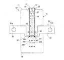
- FIG. 1 (a) is an axial sectional view of an electric circuit breaker according to the present invention
- FIG. 1 (b) is a partial sectional view of FIG. 1 (a)
- FIG. 1 (c) is a sectional view of the prior art corresponding to FIG.
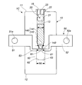
- FIG. 2 is an axial cross-sectional view of another embodiment of the electric circuit breaker of FIG. 1 (a).
- FIG. 3 is an axial cross-sectional view of yet another embodiment of the electric circuit breaker of FIG. 1 (a).
- FIG. 4 is an axial cross-sectional view of yet another embodiment of the electric circuit breaker of FIG. 1 (a).
- FIG. 5 is an axial cross-sectional view of still another embodiment of the electric circuit breaker of FIG. 1 (a).
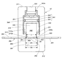
- 6 is an axial cross-sectional view of yet another embodiment of the electric circuit breaker of FIG. 1 (a).
- An object of the present invention is to provide an electric circuit breaker capable of extinguishing even when an arc occurs at the time of cutting of a conductor piece.
- the circuit breaker of the present invention is used in various electric circuits such as a battery of a gasoline or diesel car (such as a lithium ion battery), an electric circuit of an electric car, a home appliance, etc. to cause an abnormality in the electric circuit. When it can cut off the electric circuit.
- a battery of a gasoline or diesel car such as a lithium ion battery
- an electric circuit of an electric car such as a home appliance, etc. to cause an abnormality in the electric circuit. When it can cut off the electric circuit.
- the electric circuit breaker according to the present invention can be mounted alone on the various vehicles described above, but can also be mounted so that it can be operated in conjunction with, for example, an airbag apparatus mounted on the vehicle.
- the electric circuit cut-off device of the present invention is also operated to cut the electric circuit in response to the operation signal of the air bag device. Can prevent the leakage of a large current.
- the housing is made of a synthetic resin, and has a cylindrical space formed from the first end side toward the second end side opposite to the housing in the axial direction, and the second space of the cylindrical space is formed. The end side is connected to the insulating closed space via the conductor piece.
- the outer shape of the housing is appropriately determined in accordance with the mounting site.
- the housing is of a shape, structure and size that can accommodate and attach components such as igniters, projectiles, conductor strips and the like.
- the housing may be composed of a first housing from the first end to a portion where the conductor piece is installed, and a second housing (bottom clip) from the portion where the conductor piece is installed to the second end. it can.
- the igniter is, in addition to an igniter used in a known electric circuit interrupting device, an igniter for a gas generator used in an air bag device of a car and the like.
- the igniter is provided with an ignition unit provided with an igniter and a conductive pin for electrifying. In operation, the igniter is burned by energizing from an external power source, and combustion products such as combustion gas and flame are produced. To generate
- the rod-like projectile receives the pressure of the combustion product generated by the operation of the igniter, moves in the axial direction in the housing, cuts the conductor piece, and shuts off the electric circuit.
- the rod-like projectile may have a uniform outer diameter (uniform width) as a whole, or may have a tip portion larger or smaller than other portions.
- the tip end portion of the rod-like projectile has a quadrangular prism shape (the cross-sectional shape in the width direction of the housing is a quadrangle) because the conductor pieces can be easily cut, and the cross-sectional shape is preferably square.
- the rod-like projectile can be made of the same synthetic resin as the housing.
- the conductor pieces can be the same as those used in known electric circuit breakers.
- the conductor piece is a plate piece consisting of the connection part (the first connection part and the second connection part) on both end sides and the cut part of the middle part, and when attached to the electric circuit, forms a part of the electric circuit. It is a thing.
- the shape of the conductor piece is a plate shape corresponding to the shape and structure of the attachment portion to the housing. The conductor piece is disposed between the cylindrical space and the insulating closed space.
- the width (W1) of the opening of the insulating closed space of the housing and the width (L1) of the tip of the rod-like projectile have a relationship of W1> L1 and W1-L1 ⁇ 0.25 mm. 0.5 mm or more is preferable, 0.8 mm or more is more preferable, 2 mm or less is preferable, and 1.5 mm or less is more preferable.
- the rod-like projectile When the width (W1) of the opening of the insulating closed space and the width (L1) of the tip of the rod-like projectile have the above-mentioned relationship, the rod-like projectile At the same time when the first end side is pressed, the other surface side (second end side of the housing) of the cut portion of the conductor piece is at the corner of the boundary between the opening of the insulating closed space and the four side portions. Being pushed in the hit state, it becomes easy to be cut off. Therefore, the output of the igniter that applies pressure to the rod-like projectile can be reduced, and the electric circuit breaker itself can also be miniaturized.
- the insulating closed space has a relationship in which the width (W1) of the opening and the width (W2) of the closed end face satisfy W1> W2,
- the width (W2) of the end face and the width (L1) of the tip of the rod-like projectile have a relationship of W2> L1.
- the insulating closed space has a relationship in which the width (W1) of the opening and the width (W2) of the closed end face satisfy W1> W2,
- the width (W2) of the end face and the width (L1) of the tip end portion of the rod-like projectile have a relation of W2 ⁇ L1, and on the inclined surface where the four side faces from the opening to the closed end face are continuous. It is what has become.
- the insulating enclosed space has a width (W1) of the opening, a width (W3) between the opposite side surfaces, and a width (W2) of the closed end surface.
- W1> W2 W3
- W2 W3
- An annular step portion is formed by the difference in width (W1-W3) at the boundary between the opening and the four side surfaces.
- W1> W2 W2> L1 and W2-L1 ⁇ 0.25 mm, even when an arc is generated when the conductor piece is cut, it is easy to extinguish the arc.
- the rod-like projectile has a main body with a large width and a tip with a smaller width than the main body, and the main body and the main body Between the tip end portions is an inclined surface, and the insulating closed space has a width (W1) of the opening, a width (W3) between opposing side surfaces, and a width (W2) of the closed end surface is W1.
- the width (W2) of the closed end face and the width (L1) of the tip end of the rod-like projectile have a relation of W2> L1, and the closed end face
- the width (W2) and the width (L2) of the main body of the rod-like projectile have a relationship of W2-L2 ⁇ 0.25 mm.
- the rod-like projectile has a main body with a large width and a tip with a smaller width than the main body, and the main body and the main body
- the front end portion is a step surface
- the insulating closed space has a width (W1) of the opening, a width (W3) between opposing side surfaces, and a width (W2) of the closed end surface is W1.
- the width (W2) of the closed end face and the width (L1) of the tip end of the rod-like projectile have a relation of W2> L1, and the closed end face
- the width (W2) and the width (L2) of the main body of the rod-like projectile have a relationship of W2-L2 ⁇ 0.25 mm.
- the conductor piece is easily cut off under the action of both the rod-like projectile and the corner of the opening of the insulating closed space in operation, the pressure is applied to the rod-like projectile The output of the igniter for addition can be reduced.
- the housing (resin housing) 10 made of synthetic resin has a cylindrical space 13 penetrating from the first end 11 to the conductor piece 50 on the second end 12 opposite to the housing axial direction.
- a connector fitting portion 15 for connecting the igniter 20 and a power supply with a lead wire at the time of use is attached to the first end 11 side of the cylindrical space 13.
- an igniter 20, a rod-like projectile 40 made of a synthetic resin, and a conductor piece 50 are disposed in this order from the first end 11 side to the second end 12 side.
- the housing 10, the cylindrical space 13, the igniter 20, and the rod-like projectile 40 are arranged such that their central axes coincide with each other.
- the igniter 20 has a resin portion 22 in which a part of the igniter main body having the igniter 21 and the conductive pin 23 is surrounded by resin, and the igniter 21 protrudes from the resin portion 22.
- the rod-like projectile 40 is disposed so as to be able to move in the cylindrical space 13, and the cross-sectional shape in the width direction of the housing of the tip end portion 41 is a square.
- the cross-sectional shape of the portion of the rod-like projectile 40 excluding the tip end portion 41 is not particularly limited.
- a cylinder for reinforcing the housing 10 can be disposed as needed.
- the cylinder is preferably made of a metal such as stainless steel or aluminum, or a fiber reinforced resin such as a carbon fiber reinforced resin.
- the conductor piece 50 is for forming a part of an electric circuit, when the electric circuit breaker 1 is attached to an electric circuit.
- the conductor piece 50 is a plate piece including the first connection portion 51 at both ends and the second connection portion 52 and the cut portion 53 at the middle portion.
- the first connection portion 51 (hole 51a of the first connection portion 51) and the second connection portion 52 (hole 52a of the second connection portion 52) are for connection to another conductor (for example, a lead wire) in the electric circuit.
- the cutting portion 53 is intended to be cut at the time of operation to cut off the electric circuit.
- the surface of the cut portion 53 of the conductor piece 50 is disposed in the width direction of the housing 10.
- the surface of the cut portion 53 of the conductor piece 50 is opposed to the tip end portion 41 of the rod-like projectile 40.
- the surface of the cutting portion 53 and the tip end portion 41 are in contact with each other, but may be opposed to each other at an interval.
- An insulating closed space 60 is formed between the conductor piece 50 and the second end 12 of the housing.
- the insulating closed space 60 has a square cross-sectional shape in the width direction of the housing, and the opening 61 facing the conductor piece 50, the closed end face 62 facing the opening 61 and the axial direction of the housing, the opening 61 closed There are four side faces 63 between the end faces 62. At the boundary between the opening 61 and the four side surfaces 63, a corner 64 of about 90 degrees is formed.
- the electric circuit breaker shown in FIG. 1 is manufactured by injection molding with the conductor piece 50 disposed in the mold, and then the necessary parts are inserted from one end side of the cylindrical space 13 to manufacture the mold. After molding the first housing from the first end 11 to the portion where the conductor piece 50 is installed by injection molding in a state where the conductor piece is disposed inside, necessary parts from both ends of the cylindrical space 13 The method of injection molding in a state where the inserted one is placed again in the mold and molding and manufacturing the second housing (bottom clip) from the portion where the conductor piece 50 is installed to the second end 12 is applied can do.
- the electric circuit breaker 1 shown in FIG. 1 can be combined with a sensor for detecting an abnormal current, for example, to automatically start operation when an abnormal current flows in the electric circuit, or artificially It can also be made to operate.
- the holes 51a of the first connection portion 51 of the conductor piece 50 and the holes 52a of the second connection portion 52 are connected to the lead wires forming the electric circuit.
- the igniter 20 operates to generate combustion products from the igniter 21.
- the combustion product generated from the ignition unit 21 travels straight in the cylindrical space 13 and collides with the rod-like projectile 40.
- the tip end portion 41 of the rod-like projectile 40 which receives the pressure by the combustion product moves in the axial direction and cuts the cutting portion 53 of the conductor piece 50.
- the tip 41 of the rod-like projectile 40 is a conductor piece 50 at the time of operation.
- the cutting portion 53 is pushed, the cutting portion 53 of the conductor piece 50 is simultaneously pushed into the corner portion 64 of the boundary portion between the opening 61 and the four side surfaces 63, so the cutting portion 53 is a housing It is easily cut off under the action from both sides in the axial direction.
- Electric circuit breaker 1A of FIG. 2 is the same as the electrolytic circuit means 1 shown in FIG. 1 except that the shape of the insulating space 160 is different.
- An insulating closed space 160 is formed between the conductor piece 50 and the second end 12 of the housing.
- the insulating closed space 160 has a square cross-sectional shape in the width direction of the housing, and the opening 161 facing the conductor piece 50, the closed end surface 162 facing the opening 161 and the housing in the axial direction, the opening 161 closed
- the boundary between the opening 161 and the four side surfaces 163 is formed with a corner of about 80 degrees to less than about 90 degrees.
- the width (W1) of the opening 161 and the width (W2) of the closed end surface 162 have a relationship of W1> W2, and the four side surfaces 163 from the opening 161 to the closed end surface 162 are It is a continuous slope.
- the igniter 20 of the electric circuit interrupting device 1A of FIG. 2 is operated, and the tip 41 of the rod-like projectile 40 which receives the pressure by the combustion product is moved in the axial direction of the housing to cut the conductor piece 50 Cut 53.
- the tip end portion 41 of the rod-like projectile and the cut piece of the cutting portion 53 move to the closed end surface 162 and are electrically insulated and held.
- the first connection portion 51 and the second connection portion 52 located at both ends of the conductor piece 50 are electrically disconnected, and the electric circuit in which the device 1 is disposed is cut off. Even when the conductor piece 50 is cut in such a process and an arc is generated between the first connection portion 51 and the second connection portion 52, the arc is extinguished because W2 ⁇ L1. Be done.
- the housing 10 can be miniaturized and the device 1A can be miniaturized.
- Electric circuit breaker 1B of FIG. 3 The electric circuit breaker 1B shown in FIG. 3 is the same as the electrolytic circuit means 1 shown in FIG. 1 except that the shape of the insulating space 260 is different.
- an annular step portion 264 is formed by the difference (W1-W3) of the widths thereof.
- the insulating closed space 260 has a relationship in which the width (W2) of the closed end surface 262 and the width (L1) of the tip portion 41 of the rod-like projectile 40 satisfy W2> L1 and W2-L1 ⁇ 0.25 mm.
- the boundary between the opening 261 of the insulating space 260 and the four side surfaces 263 is formed with a corner of about 90 degrees.
- the igniter 20 of the electric circuit interrupting device 1B of FIG. 3 is actuated, and the tip 41 of the rod-like projectile 40 which receives the pressure by the combustion product moves in the axial direction of the housing to cut the conductor piece 50 Cut 53.
- the tip end portion 41 of the rod-like projectile 40 pushes the cut portion 53 of the conductor piece 50 at the time of operation, the conductor piece 50 simultaneously. Since the cutting portion 53 is pushed in contact with the corner of the boundary between the opening 261 and the four side surfaces 263, it is easily cut under the action from both sides in the axial direction of the housing. For this reason, the output of the igniter 20 which applies pressure to the rod-like projectile 40 can be reduced, and the electric circuit breaker 1 itself can also be miniaturized.
- Electric circuit breaker 1C shown in FIG. 4 is the same as the electric circuit breaker 1 shown in FIG. 1 except that the shape of the tip portion 142 of the rod-like projectile 140 is different.
- the rod-like projectile 140 has a large-width main body portion 141 and an inclined tip portion 142 whose width decreases continuously toward the tip end surface 143.
- the cross-sectional shape of the housing in the width direction of the inclined tip portion 142 including the tip surface 143 is a square, and the width of the tip surface 143 is L1.
- the igniter 20 of the electric circuit breaker 1C of FIG. 4 is actuated, and the tip end surface 143 of the rod-like projectile 140 which receives the pressure by the combustion product is moved in the axial direction of the housing to cut the conductor piece 50 Cut 53.
- the tip end surface 143 of the rod-like projectile 140 pushes the cut portion 53 of the conductor piece 50 at the time of operation, the conductor piece 50 simultaneously. Since the cutting portion 53 is pushed into contact with the corner of the boundary between the opening 61 and the four side surfaces 63, it is easily cut under the action of both sides in the axial direction of the housing. For this reason, the output of the igniter 20 which applies pressure to the rod-like projectile 140 can be reduced, and the electric circuit breaker 1 itself can be miniaturized.
- the tip end surface 143 of the rod-like projectile and the cut piece of the cutting portion 53 move to the closed end surface 62 and are electrically insulated and held.
- the first connection portion 51 and the second connection portion 52 at both ends of the conductor piece 50 are electrically disconnected, and the electric circuit in which the device 1C is disposed is cut off. Even when the conductor piece 50 is cut in such a process and an arc is generated between the first connection portion 51 and the second connection portion 52, the relationship of W2> L1 and W2-L2 ⁇ 0.25 mm is satisfied. The arc is extinguished.
- Electric circuit breaker 1D of FIG. 5 The electric circuit breaker 1D shown in FIG. 5 is the same as the electric circuit breaker 1 shown in FIG. 1 except that the shape of the rod-like projectile 240 is different.
- the rod-like projectile 240 has a main body portion 241 having a large width and a distal end portion 242 having a smaller width than the main body portion 241, and a step surface 243 is formed between the main body portion 241 and the distal end portion 242.
- the cross-sectional shape in the width direction of the housing of the tip end portion 241 is a square, and the width of the tip end portion 242 is L1.
- the igniter 20 of the electric circuit interrupting device 1D of FIG. 5 is actuated, and the tip portion 242 of the rod-like projectile 240 which receives the pressure by the combustion product moves in the axial direction of the housing to cut the conductor piece 50 Cut 53.
- the tip end 242 of the rod-like projectile 240 pushes the cut portion 53 of the conductor piece 50 at the time of operation, the conductor piece 50 simultaneously. Since the cutting portion 53 is pushed into contact with the corner of the boundary between the opening 61 and the four side surfaces 63, it is easily cut under the action of both sides in the axial direction of the housing. Therefore, the output of the igniter 20 that applies pressure to the rod-like projectile 240 can be reduced, and the electric circuit breaker 1 itself can also be miniaturized.
- the distal end portion 242 of the rod-like projectile 240 and the cut piece of the cutting portion 53 move to the closed end surface 62 and are electrically insulated.
- the first connection portion 51 and the second connection portion 52 at both ends of the conductor piece 50 are electrically disconnected, and the electric circuit in which the device 1D is disposed is cut off.
- the conductor piece 50 is cut in such a process and an arc is generated between the first connection portion 51 and the second connection portion 52, the relationship of W2> L1 and W2-L2 ⁇ 0.25 mm is satisfied. The arc is extinguished.
- Electric circuit breaker 1E of FIG. 6 is different from the electric circuit breaker 1 shown in FIG. 1 in the shape of the rod-like projectile 340, the shape of the cylindrical space 313, and the shape of the conductor piece 350. Other than being used, it is substantially the same as the electric circuit breaker 1 shown in FIG.
- the housing (resin housing) 310 made of synthetic resin has a cylindrical space 313 which is penetrated from the first end portion 311 to the conductor piece 350 on the second end portion 312 side.
- the cylindrical space 313 has a large diameter cylindrical space 313 a on the first end side and a small diameter cylindrical space 313 b on the second end 312 side.
- the rod-like projectile 340 has a base portion 341 and a rod portion 345, and the outer diameter of the base portion 341 is larger than the outer diameter of the rod portion 345.
- the cross-sectional shape of the base portion 341 in the housing width direction is circular, and the cross-sectional shape of the rod portion 345 in the housing width direction is rectangular.
- the base portion 341 has a first base portion 342 facing the igniter 320, a third base portion 344 in contact with the rod portion 345, and a second base portion 343 in the middle.
- the surface on the igniter 320 side of the first base portion 342 has a deep concave curved surface at the central portion, and the igniter 320 is activated to easily receive the pressure generated.
- the outer diameters of the first base portion 342 and the third base portion 344 are substantially the same, and are in contact with the inner circumferential surface of the cylinder 330. Since the outer diameter of the second base portion 343 is smaller than the first base portion 342 and the third base portion 344, O in the annular space around the second base portion 343 formed due to the outer diameter difference. A ring 346 is arranged.
- the cylinder 330 is for reinforcing the housing 310 and is made of a metal such as stainless steel or aluminum, or a fiber reinforced resin such as a carbon fiber reinforced resin.
- the cross-sectional shape in the housing width direction of the cylinder 330 is circular.
- the cylinder 330 surrounds the igniter 321 and the projectile 340 of the igniter 320 and is fixed so as not to move in the axial direction by being pressed into the cylindrical space 313.
- the cylinder 330 surrounds the igniter 321 and the projectile 340 of the igniter 320 and is fixed so as not to move in the axial direction by being pressed into the cylindrical space 313.
- a plurality of two notches cut at predetermined intervals are formed at equal intervals.
- the two cut portions inserted at predetermined intervals are bent inward, and the bent portion functions as a guide portion 331 of the rod portion 345.
- the conductor piece 350 is for forming a part of the electric circuit when the device 1E is attached to the electric circuit.
- the conductor piece 350 is a plate piece including the first connection portion 351 at both ends, the second connection portion 352, and the cut portion 353 at the middle portion.
- the first connection portion 351 and the second connection portion 352 are for connection to another conductor (for example, a lead wire) in the electric circuit, and the cutting portion 353 is cut at the time of operation and can cut off the electric circuit. It is intended to
- the conductor piece 350 is disposed such that the surface of the cut portion 353 is orthogonal to the axial direction of the housing 310.
- the surface of the cut portion 353 of the conductor piece 350 is opposed to the end surface of the rod portion 345 of the projectile 340.
- the surface of the cutting portion 353 and the tip end surface of the rod portion 345 are in contact with each other, but they may be opposed with an interval.
- the insulating closed space 360 has a square cross-sectional shape in the width direction of the housing, and has an opening 361 facing the conductor piece 350, a closed end surface 362 facing the opening 361 and the housing in the axial direction, and an opening 361 There are four side surfaces 363 between the end faces 362. At the boundary between the opening 361 and the four side surfaces 363, a corner 364 of about 90 degrees is formed.
- the electric circuit breaker 1E shown in FIG. 6 is manufactured by injection molding with the conductor pieces arranged in the mold, and then by inserting necessary parts from one end side of the cylindrical space 313, the mold After the first housing from the first end 311 to the portion where the conductor piece 350 is installed is molded by injection molding in a state where the conductor piece is disposed in the inside, necessary parts from both ends of the cylindrical space 313
- the method of injection molding in a state where the inserted one is placed again in the mold and molding and manufacturing the second housing (bottom clip) from the portion where the conductor piece 350 is installed to the second end 312 is applied can do.
- the electric circuit breaker 1E of FIG. 6 When the electric circuit breaker 1E of FIG. 6 operates, it operates in the same manner as the electric circuit breaker 1 shown in FIG. 1 to cut the conductor piece 350, and the first connection portion 351 and the second connection at both ends of the conductor piece 350. Since the unit 352 is electrically disconnected, the electric circuit in which the device 1E is disposed is cut off. In the embodiment of FIG.
- the electric circuit breaker of the present invention is suitable for various electric circuits, for example, electric circuits including car batteries (for example, lithium ion batteries), electric circuits of electric cars, and electric circuits of home appliances. In particular, they are suitable for use in electrical circuits including automotive batteries (eg lithium ion batteries).
Landscapes
- Breakers (AREA)
- Fuses (AREA)
- Circuit Breakers (AREA)
- Distribution Board (AREA)
- Air Bags (AREA)
Abstract
小さな出力で導体片を切断できる電気回路遮断装置の提供。ハウジングの第1端部側からハウジングの軸方向反対側の第2端部側に向かって形成された筒状空間内に順に、点火器、棒状発射体、電気回路の一部を形成させるための導体片が配置され、ハウジングの第2端部と導体片の間に絶縁閉鎖空間を有しており、導体片が、両端側の第1接続部、第2接続部と中間の切断部からなる板片であり、切断部面が前記ハウジングの幅方向に配置されており、棒状発射体が、先端部のハウジングの幅方向の断面形状が四角形のもので、導体片の切断部の面とハウジングの軸方向に配置されているものであり、絶縁閉鎖空間が、ハウジングの幅方向の断面形状が四角形であり、導体片に面した開口部、開口部とハウジングの軸方向に対向した閉塞端面、開口部と閉塞端面の間の4つの側面を有しているものであり、絶縁閉鎖空間の開口部の幅(W1)と棒状発射体の先端部の幅(L1)がW1>L1で、W1-L1≧0.25mmの関係を有している、電気回路遮断装置。
Description
本発明は、自動車や家庭電化製品などの電気回路に使用することができる電気回路遮断装置に関する。
背景技術
自動車や家庭電化製品などの電気回路自体や前記電気回路を含むシステム全体の異常時などにおいて、電気回路を遮断することで大きな被害を未然に防止する電気回路遮断装置が使用されており、電気自動車の電気回路では電気回路遮断装置の重要性が特に大きくなっている。電気回路遮断装置は、ハウジング内に点火器、発射体(ピストン)、導体などが収容されたものが知られている(US2005/0083164A、US2005/0083165A、US2012/0234162A、JPH11-232979A、JP2014-49300A、JP2016-85947A、JP2014-49300A)。
自動車や家庭電化製品などの電気回路自体や前記電気回路を含むシステム全体の異常時などにおいて、電気回路を遮断することで大きな被害を未然に防止する電気回路遮断装置が使用されており、電気自動車の電気回路では電気回路遮断装置の重要性が特に大きくなっている。電気回路遮断装置は、ハウジング内に点火器、発射体(ピストン)、導体などが収容されたものが知られている(US2005/0083164A、US2005/0083165A、US2012/0234162A、JPH11-232979A、JP2014-49300A、JP2016-85947A、JP2014-49300A)。
US2005/0083164A、US2005/0083165Aでは、ハウジングの材質として、金属、セラミックス、ポリマーが例示されており、特定のポリマーが好ましいと記載されている(US2005/0083164Aの2~3頁、US2005/0083165Aの2頁)。
JPH11-232979Aでは、ケーシング13はステンレスからなるものである(段落番号0011)。
JP2014-49300Aでは、ケース30は、電気絶縁性を有し、かつ強度の高い材料(例えば樹脂材料)によって形成されている(段落番号0034)。ポリマー材料(樹脂材料)を使用したときは、例えば、US2005/0083164A、US2005/0083165A、JP2014-49300Aのそれぞれの図1などからも理解できるとおり、必要な強度を付与する点から、ハウジング(ケーシング)を厚肉にする必要がある。ステンレスのケーシング13を使用したときは、質量の増加が大きくなるほか、絶縁ケース14を組み合わせて配置する必要があるため、構造および組み立てが複雑になる。
JP2016-85947Aは、金属製のシリンダーを使用して樹脂製のハウジングを補強することで、US2005/0083164A、US2005/0083165A、US2012/0234162A、JPH11-232979A、JP2014-49300Aにはない作用効果が得られている。
JP2014-49300Aは、通電状態の導電体が切断されたときに発生するアークを消弧するための消弧室32が設けられている(特許請求の範囲)。
発明の開示
本発明は、合成樹脂からなるハウジング内において、前記ハウジングの第1端部からハウジングの軸方向反対側の第2端部に向かって形成された筒状空間内に順に、点火器、合成樹脂からなる棒状発射体、電気回路の一部を形成させるための導体片が配置され、前記ハウジングの第2端部と前記導体片の間に絶縁閉鎖空間を有しており、
前記導体片が、両端側の第1接続部、第2接続部と中間部分の切断部からなる板片であり、前記切断部の面が前記ハウジングの軸方向に直交するハウジングの幅方向に配置されており、
前記棒状発射体が、先端部のハウジングの幅方向の断面形状が四角形のもので、前記導体片の切断部の面とハウジングの軸方向に対向して配置されているものであり、
前記絶縁閉鎖空間が、ハウジングの幅方向の断面形状が四角形であり、前記導体片に面した開口部、前記開口部とハウジングの軸方向に対向した閉塞端面、前記開口部と前記閉塞端面の間の4つの側面を有しているものであり、
前記絶縁閉鎖空間の開口部の幅(W1)と前記棒状発射体の先端部の幅(L1)がW1>L1で、W1-L1≧0.25mmの関係を有している、電気回路遮断装置を提供する。
本発明は、合成樹脂からなるハウジング内において、前記ハウジングの第1端部からハウジングの軸方向反対側の第2端部に向かって形成された筒状空間内に順に、点火器、合成樹脂からなる棒状発射体、電気回路の一部を形成させるための導体片が配置され、前記ハウジングの第2端部と前記導体片の間に絶縁閉鎖空間を有しており、
前記導体片が、両端側の第1接続部、第2接続部と中間部分の切断部からなる板片であり、前記切断部の面が前記ハウジングの軸方向に直交するハウジングの幅方向に配置されており、
前記棒状発射体が、先端部のハウジングの幅方向の断面形状が四角形のもので、前記導体片の切断部の面とハウジングの軸方向に対向して配置されているものであり、
前記絶縁閉鎖空間が、ハウジングの幅方向の断面形状が四角形であり、前記導体片に面した開口部、前記開口部とハウジングの軸方向に対向した閉塞端面、前記開口部と前記閉塞端面の間の4つの側面を有しているものであり、
前記絶縁閉鎖空間の開口部の幅(W1)と前記棒状発射体の先端部の幅(L1)がW1>L1で、W1-L1≧0.25mmの関係を有している、電気回路遮断装置を提供する。
本発明は、以下の詳細な説明と添付された図面により、さらに完全に理解されるものであるが、これらはただ説明のため付されるものであり、本発明を制限するものではない。
発明の詳細な説明
本発明は、導体片の切断時にアークが生じたときでも消弧できる電気回路遮断装置を提供することを課題とする。
本発明は、導体片の切断時にアークが生じたときでも消弧できる電気回路遮断装置を提供することを課題とする。
本発明の電気回路遮断装置は、ガソリンまたはディーゼル自動車のバッテリー(リチウムイオンバッテリーなど)、電気自動車の電気回路、家庭電化製品などの様々な電気回路に取り付けて使用して、電気回路に異常が生じたときには、電気回路を遮断できるものである。
本発明の電気回路遮断装置は、単独で前記した各種自動車に取り付けることもできるが、例えば、自動車に搭載されたエアバッグ装置と連動して作動できるようにして取り付けることもできる。このような場合には、エアバッグ装置が搭載された各種自動車が事故を起こしたとき、エアバッグ装置の作動信号を受けて本発明の電気回路遮断装置も作動して電気回路が遮断されるようにすることで、大電流の漏電を防止できる。
ハウジングは合成樹脂からなるものであり、第1端部側からハウジングの軸方向反対側の第2端部側に向かって形成された筒状空間を有しており、前記筒状空間の第2端部側は導体片を介して絶縁閉鎖空間に繋がっている。ハウジングの外形は取り付け部位に応じて適宜決定されるものである。ハウジングは、点火器、発射体、導体片などの部品を収容したり、取り付けたりすることができる形状、構造および大きさのものである。ハウジングは、第1端部から導体片が設置された部分までの第1ハウジングと、導体片が設置された部分から第2端部までの第2ハウジング(ボトムクリップ)からなるものにすることもできる。
点火器は、公知の電気回路遮断装置で使用されている点火器のほか、自動車のエアバッグ装置で使用するガス発生器用の点火器などである。点火器は、点火薬を備えた点火部と通電するための導電ピンを備えたものであり、作動時には、外部電源から通電することで点火薬を燃焼させ、燃焼ガスや火炎などの燃焼生成物を発生させるものである。
棒状発射体は、点火器の作動により発生した燃焼生成物の圧力を受けて、ハウジング内を軸方向に移動し、導体片を切断して、電気回路を遮断するためのものである。棒状発射体は、全体が均一外径(均一幅)のものでもよいし、先端部が他の部分に比べて大きくなっているものでもよいし、小さくなっているものでもよい。棒状発射体の先端部は、導体片の切断が容易であることから、四角柱形状(ハウジングの幅方向の断面形状が四角形)であり、前記断面形状が正方形のものが好ましい。棒状発射体は、ハウジングと同じ合成樹脂からなるものを使用することができる。
導体片は、公知の電気回路遮断装置で使用されているものと同じものを使用することができる。導体片は、両端側の接続部(第1接続部と第2接続部)と中間部分の切断部からなる板片であり、電気回路に取り付けたとき、電気回路の一部を形成するためのものである。導体片の形状は、ハウジングに対する取り付け部分の形状および構造に対応した板形状になっている。導体片は、筒状空間と絶縁閉鎖空間の間に配置されている。
ハウジングの絶縁閉鎖空間の開口部の幅(W1)と棒状発射体の先端部の幅(L1)は、W1>L1で、W1-L1≧0.25mmの関係を有している。W1-L1は0.5mm以上が好ましく、0.8mm以上がより好ましく、2mm以下が好ましく、1.5mm以下がより好ましい。絶縁閉鎖空間の開口部の幅(W1)と棒状発射体の先端部の幅(L1)が前記関係を有していると、作動時に棒状発射体が導体片の切断部の一面側(ハウジングの第1端部側)を押したとき、それと同時に導体片の切断部の他面側(ハウジングの第2端部側)が絶縁閉鎖空間の開口部と4つの側面部の境界部の角部に当たった状態で押し込まれるようになるため、切断されやすくなる。このため、棒状発射体に圧力を加える点火器の出力を小さくすることができるようになり、電気回路遮断装置自体も小型化ができるようになる。
本発明の電気回路遮断装置の好ましい実施形態は、前記絶縁閉鎖空間が、前記開口部の幅(W1)と前記閉塞端面の幅(W2)がW1>W2の関係を有しており、前記閉塞端面の幅(W2)と前記棒状発射体の先端部の幅(L1)がW2>L1の関係を有しているものである。
W2>L1の関係を有していることで、導体片が切断されたときにアークが発生しても消弧され易くなっている。
本発明の電気回路遮断装置の好ましい別の実施形態は、前記絶縁閉鎖空間が、前記開口部の幅(W1)と前記閉塞端面の幅(W2)がW1>W2の関係を有し、前記閉塞端面の幅(W2)と前記棒状発射体の先端部の幅(L1)がW2<L1の関係を有しており、前記開口部から前記閉塞端面までの前記4つの側面が連続した傾斜面になっているものである。
W1>W2、W2<L1の関係を有しており、4つの側面が傾斜面になっていることで、作動時における棒状発射体の運動エネルギーを徐々に吸収できると共に、導体片が切断されたときにアークが発生しても消弧され易くなっている。
本発明の電気回路遮断装置の好ましいさらに別の実施形態は、前記絶縁閉鎖空間が、前記開口部の幅(W1)、前記対向する側面間の幅(W3)および前記閉塞端面の幅(W2)が、W1>W2=W3の関係を有し、前記閉塞端面の幅(W2)と前記棒状発射体の先端部の幅(L1)がW2>L1、かつW2-L1≦0.25mmの関係を有しており、前記開口部と前記4つの側面の境界部に幅の差(W1-W3)による環状段差部が形成されているものである。
W1>W2、W2>L1、W2-L1≦0.25mmの関係を有していることで、導体片が切断されたときにアークが発生しても消弧され易くなっている。
本発明の電気回路遮断装置の好ましいさらに別の実施形態は、前記棒状発射体が、幅の大きな本体部と、前記本体部よりも幅の小さい先端部を有しており、前記本体部と前記先端部の間が傾斜面になっているものであり、前記絶縁閉鎖空間が、前記開口部の幅(W1)、対向する側面間の幅(W3)および前記閉塞端面の幅(W2)がW1=W3=W2の関係を有しており、前記閉塞端面の幅(W2)と前記棒状発射体の先端部の幅(L1)がW2>L1の関係を有しており、かつ前記閉塞端面の幅(W2)と前記棒状発射体の本体部の幅(L2)がW2-L2≦0.25mmの関係を有しているものである。
W1=W3=W2、W2>L1、W2-L2≦0.25mmの関係を有していることで、導体片が切断されたときにアークが発生しても消弧され易くなっている。
本発明の電気回路遮断装置の好ましいさらに別の実施形態は、前記棒状発射体が、幅の大きな本体部と、前記本体部よりも幅の小さい先端部を有しており、前記本体部と前記先端部の間が段差面になっているものであり、前記絶縁閉鎖空間が、前記開口部の幅(W1)、対向する側面間の幅(W3)および前記閉塞端面の幅(W2)がW1=W3=W2の関係を有しており、前記閉塞端面の幅(W2)と前記棒状発射体の先端部の幅(L1)がW2>L1の関係を有しており、かつ前記閉塞端面の幅(W2)と前記棒状発射体の本体部の幅(L2)がW2-L2≦0.25mmの関係を有しているものである。
W1=W3=W2、W2>L1、W2-L2≦0.25mmの関係を有していることで、導体片が切断されたときにアークが発生しても消弧され易くなっている。
本発明の電気回路遮断装置は、作動時において導体片が棒状発射体と絶縁閉鎖空間の開口部の角部の両方からの作用を受けて切断され易くなっているため、棒状発射体に圧力を加えるための点火器の出力を小さくすることができる。
発明の実施の形態
(1)図1の電気回路遮断装置1
合成樹脂からなるハウジング(樹脂ハウジング)10は、第1端部11からハウジング軸方向反対側の第2端部12側の導体片50まで貫通された筒状空間13を有している。筒状空間13の第1端部11側には、使用時において点火器20と電源をリードワイヤで接続するためのコネクタ嵌め込み部15が取り付けられている。筒状空間13内には、第1端部11側から第2端部12側に順に点火器20、合成樹脂からなる棒状発射体40、導体片50が配置されている。ハウジング10、筒状空間13、点火器20、棒状発射体40は、それぞれの中心軸が一致するように配置されている。
(1)図1の電気回路遮断装置1
合成樹脂からなるハウジング(樹脂ハウジング)10は、第1端部11からハウジング軸方向反対側の第2端部12側の導体片50まで貫通された筒状空間13を有している。筒状空間13の第1端部11側には、使用時において点火器20と電源をリードワイヤで接続するためのコネクタ嵌め込み部15が取り付けられている。筒状空間13内には、第1端部11側から第2端部12側に順に点火器20、合成樹脂からなる棒状発射体40、導体片50が配置されている。ハウジング10、筒状空間13、点火器20、棒状発射体40は、それぞれの中心軸が一致するように配置されている。
点火器20は、点火部21と導電ピン23を有する点火器本体の一部が樹脂で包囲された樹脂部22を有しており、樹脂部22から点火部21が突き出されたものである。
棒状発射体40は、筒状空間13内を移動できるように配置されているもので、先端部41のハウジングの幅方向の断面形状が正方形のものである。棒状発射体40は、先端部41を除いた部分の断面形状は特に制限されるものではない。ハウジング10と棒状発射体40の間には、必要に応じて、ハウジング10を補強するためのシリンダーを配置することができる。シリンダーは、ステンレス、アルミニウムなどの金属、炭素繊維強化樹脂などの繊維強化樹脂からなるものが好ましい。
導体片50は、電気回路遮断装置1を電気回路に取り付けたとき、電気回路の一部を形成させるためのものである。導体片50は、両端側の第1接続部51、第2接続部52と中間部分の切断部53からなる板片である。第1接続部51(第1接続部51の穴51a)と第2接続部52(第2接続部52の穴52a)は、電気回路において他の導体(例えば、リードワイヤ)と接続するためのものであり、切断部53は、作動時において切断されて電気回路を遮断できるようにするためのものである。導体片50は、切断部53の面がハウジング10の幅方向に配置されている。導体片50の切断部53の面は、棒状発射体40の先端部41と対向している。図1では、切断部53の面と先端部41が当接されているが、間隔をおいて対向されていてもよい。
導体片50とハウジングの第2端部12の間には、絶縁閉鎖空間60が形成されている。絶縁閉鎖空間60は、ハウジングの幅方向の断面形状が正方形のものであり、導体片50に面した開口部61、開口部61とハウジングの軸方向に対向した閉塞端面62、開口部61と閉塞端面62の間の4つの側面63を有している。開口部61と4つの側面63との境界部分には、約90度の角部64が形成されている。絶縁閉鎖空間60の開口部61の幅(W1)と棒状発射体40の先端部41の幅(L1)はW1>L1およびW1-L1=1mmの関係を有している。絶縁閉鎖空間60は、開口部61の幅(W1)、対向する二つの側面63の間の幅(W3)、閉塞端面62の幅(W2)がW1=W3=W2となっている。
図1に示す電気回路遮断装置は、金型内に導体片50を配置した状態で射出成形した後、筒状空間13の一端側から必要な部品を挿入して製造する方法のほか、金型内に導体片を配置した状態で射出成形して、第1端部11から導体片50が設置された部分までの第1ハウジングを成形した後、筒状空間13の両端側から必要な部品を挿入したものを再度金型内に配置した状態で射出成形して、導体片50が設置された部分から第2端部12までの第2ハウジング(ボトムクリップ)を成形して製造する方法を適用することができる。
次に、図1に示す電気回路遮断装置1を電気自動車の電気回路(バッテリー)の一部に配置したときの動作を説明する。図1に示す電気回路遮断装置1は、異常電流を検知するセンサーなどと組み合わせて、例えば電気回路に異常電流が流れたときに自動的に作動を開始するようにすることができるほか、人為的に作動するようにすることもできる。
電気回路遮断装置1を電気回路に配置するときは、導体片50の第1接続部51の穴51aと第2接続部52の穴52aにおいて電気回路を構成するリードワイヤと接続する。電気回路に異常が生じたときには、点火器20が作動して、点火部21から燃焼生成物が発生する。点火部21から発生した燃焼生成物は筒状空間13内を直進して、棒状発射体40に衝突する。
燃焼生成物による圧力を受けた棒状発射体40の先端部41は、軸方向に移動して、導体片50の切断部53を切断する。このとき、図1(a)、(b)に示すとおり、W1>L1およびW1-L1=1mmの関係を有していることから、作動時に棒状発射体40の先端部41が導体片50の切断部53を押したとき、それと同時に導体片50の切断部53が開口部61と4つの側面63の境界部の角部64に当たった状態で押し込まれるようになるため、切断部53はハウジングの軸方向の両側からの作用を受けて容易に切断される。このため、棒状発射体40に圧力を加える点火器20の出力を小さくすることができるようになり、電気回路遮断装置1自体も小型化ができるようになる。なお、W1=L1の場合、またはW1>L1であるが、W1-L1<0.5mmの場合には、図1(c)に示すような状態になって切断され難くなるため、導体片50を切断するためにより大きな力(より大きな点火器の出力)が必要になる。
その後、棒状発射体の先端部41と切断部53の切断片が閉塞端面62まで移動して電気絶縁的に保持される。この動作により導体片50の両端にある第1接続部51と第2接続部52は電気的に不通状態となるため、装置1を配置した電気回路は遮断される。
(2)図2の電気回路遮断装置1A
図2に示す電気回路遮断装置1Aは、絶縁空間160の形状が異なるほかは、図1に示す電解回路手段装置1と同じものである。
図2に示す電気回路遮断装置1Aは、絶縁空間160の形状が異なるほかは、図1に示す電解回路手段装置1と同じものである。
導体片50とハウジングの第2端部12の間には、絶縁閉鎖空間160が形成されている。絶縁閉鎖空間160は、ハウジングの幅方向の断面形状が正方形のものであり、導体片50に面した開口部161、開口部161とハウジングの軸方向に対向した閉塞端面162、開口部161と閉塞端面162の間の4つの側面163を有している。開口部161と4つの側面163との境界部分は約80度~約90度未満の角部が形成されている。
絶縁閉鎖空間160は、開口部161の幅(W1)と閉塞端面162の幅(W2)がW1>W2の関係を有しており、開口部161から閉塞端面162までの4つの側面163は、連続した傾斜面になっている。絶縁閉鎖空間160の開口部161の幅(W1)と棒状発射体40の先端部の幅(L1)はW1>L1およびW1-L1=1mmの関係を有しており、閉塞端面162の幅(W2)と棒状発射体の先端部141の幅(L1)はW2<L1の関係を有している。
図2の電気回路遮断装置1Aの点火器20が作動して、燃焼生成物による圧力を受けた棒状発射体40の先端部41は、ハウジングの軸方向に移動して、導体片50の切断部53を切断する。このとき、W1>L1およびW1-L1=1mmの関係を有していることから、作動時に棒状発射体40の先端部41が導体片50の切断部53を押したとき、それと同時に導体片50の切断部53が開口部161と4つの側面163の境界部の角部に当たった状態で押し込まれるようになるため、ハウジングの軸方向の両側からの作用を受けて容易に切断される。このため、棒状発射体40に圧力を加える点火器20の出力を小さくすることができるようになり、電気回路遮断装置1自体も小型化ができるようになる。
その後、棒状発射体の先端部41と切断部53の切断片が閉塞端面162まで移動して電気絶縁的に保持される。この動作により導体片50の両端にある第1接続部51と第2接続部52は電気的に不通状態となるため、装置1を配置した電気回路は遮断される。このような過程にて導体片50が切断され、第1接続部51と第2接続部52の間にアークが発生した場合でも、W2<L1の関係を有しているため、アークは消弧される。また棒状発射体40は、開口部161から閉塞端面162に向かって徐々に側面(傾斜面)163との接触強度を高めながら直進するため、運動エネルギーが徐々に吸収され、ハウジング10に対する衝撃が緩和される。このため、ハウジング10の小型化と装置1Aの小型化ができるようになる。
(3)図3の電気回路遮断装置1B
図3に示す電気回路遮断装置1Bは、絶縁空間260の形状が異なるほかは、図1に示す電解回路手段装置1と同じものである。
図3に示す電気回路遮断装置1Bは、絶縁空間260の形状が異なるほかは、図1に示す電解回路手段装置1と同じものである。
絶縁閉鎖空間260は、開口部261の幅(W1)、対向する側面263間の幅(W3)および閉塞端面262の幅(W2)が、W1>W2=W3の関係を有している。このため、開口部261と4つの側面263の境界部に、それらの幅の差(W1-W3)による環状段差部264が形成されている。さらに絶縁閉鎖空間260は、閉塞端面262の幅(W2)と棒状発射体40の先端部41の幅(L1)がW2>L1、かつW2-L1≦0.25mmの関係を有している。絶縁空間260の開口部261と4つの側面263との境界部分は約90度の角部が形成されている。
図3の電気回路遮断装置1Bの点火器20が作動して、燃焼生成物による圧力を受けた棒状発射体40の先端部41は、ハウジングの軸方向に移動して、導体片50の切断部53を切断する。このとき、W1>L1およびW1-L1=1mmの関係を有していることから、作動時に棒状発射体40の先端部41が導体片50の切断部53を押したとき、それと同時に導体片50の切断部53が開口部261と4つの側面263の境界部の角部に当たった状態で押し込まれるようになるため、ハウジングの軸方向の両側からの作用を受けて容易に切断される。このため、棒状発射体40に圧力を加える点火器20の出力を小さくすることができるようになり、電気回路遮断装置1自体も小型化ができるようになる。
その後、棒状発射体の先端部41と切断部53の切断片が閉塞端面262まで移動して電気絶縁的に保持される。この動作により導体片50の両端にある第1接続部51と第2接続部52は電気的に不通状態となるため、装置1Bを配置した電気回路は遮断される。このような過程にて導体片50が切断され、第1接続部51と第2接続部52の間にアークが発生した場合でも、W2>L1、かつW2-L1≦0.25mmの関係を有しているため、アークは消弧される。
(4)図4の電気回路遮断装置1C
図4に示す電気回路遮断装置1Cは、棒状発射体140の先端部142の形状の形状が異なるほかは、図1に示す電気回路遮断装置1と同じものである。
図4に示す電気回路遮断装置1Cは、棒状発射体140の先端部142の形状の形状が異なるほかは、図1に示す電気回路遮断装置1と同じものである。
棒状発射体140は、幅の大きな本体部141と、先端面143に向かって連続的に幅が小さくなった傾斜先端部142を有している。先端面143を含む傾斜先端部142のハウジングの幅方向の断面形状は正方形であり、先端面143の幅がL1である。
図4の電気回路遮断装置1Cの点火器20が作動して、燃焼生成物による圧力を受けた棒状発射体140の先端面143は、ハウジングの軸方向に移動して、導体片50の切断部53を切断する。このとき、W1>L1およびW1-L1=1mmの関係を有していることから、作動時に棒状発射体140の先端面143が導体片50の切断部53を押したとき、それと同時に導体片50の切断部53が開口部61と4つの側面63の境界部の角部に当たった状態で押し込まれるようになるため、ハウジングの軸方向の両側からの作用を受けて容易に切断される。このため、棒状発射体140に圧力を加える点火器20の出力を小さくすることができるようになり、電気回路遮断装置1自体も小型化ができるようになる。
その後、棒状発射体の先端面143と切断部53の切断片が閉塞端面62まで移動して電気絶縁的に保持される。この動作により導体片50の両端にある第1接続部51と第2接続部52は電気的に不通状態となるため、装置1Cを配置した電気回路は遮断される。このような過程にて導体片50が切断され、第1接続部51と第2接続部52の間にアークが発生した場合でも、W2>L1、かつW2-L2≦0.25mmの関係を有しているため、アークは消弧される。
(5)図5の電気回路遮断装置1D
図5に示す電気回路遮断装置1Dは、棒状発射体240の形状が異なるほかは、図1に示す電気回路遮断装置1と同じものである。棒状発射体240は、幅の大きな本体部241と、本体部241よりも幅の小さい先端部242を有しており、本体部241と先端部242の間が段差面243になっている。先端部241のハウジングの幅方向の断面形状は正方形であり、先端部242の幅がL1である。
図5に示す電気回路遮断装置1Dは、棒状発射体240の形状が異なるほかは、図1に示す電気回路遮断装置1と同じものである。棒状発射体240は、幅の大きな本体部241と、本体部241よりも幅の小さい先端部242を有しており、本体部241と先端部242の間が段差面243になっている。先端部241のハウジングの幅方向の断面形状は正方形であり、先端部242の幅がL1である。
図5の電気回路遮断装置1Dの点火器20が作動して、燃焼生成物による圧力を受けた棒状発射体240の先端部242は、ハウジングの軸方向に移動して、導体片50の切断部53を切断する。このとき、W1>L1およびW1-L1=1mmの関係を有していることから、作動時に棒状発射体240の先端部242が導体片50の切断部53を押したとき、それと同時に導体片50の切断部53が開口部61と4つの側面63の境界部の角部に当たった状態で押し込まれるようになるため、ハウジングの軸方向の両側からの作用を受けて容易に切断される。このため、棒状発射体240に圧力を加える点火器20の出力を小さくすることができるようになり、電気回路遮断装置1自体も小型化ができるようになる。
その後、棒状発射体240の先端部242と切断部53の切断片が閉塞端面62まで移動して電気絶縁的に保持される。この動作により導体片50の両端にある第1接続部51と第2接続部52は電気的に不通状態となるため、装置1Dを配置した電気回路は遮断される。このような過程にて導体片50が切断され、第1接続部51と第2接続部52の間にアークが発生した場合でも、W2>L1、かつW2-L2≦0.25mmの関係を有しているため、アークは消弧される。
(6)図6の電気回路遮断装置1E
図6に示す電気回路遮断装置1Eは、図1に示す電気回路遮断装置1とは棒状発射体340の形状、筒状空間313の形状、導体片350の形状が異なっており、さらにシリンダー330が使用されているほかは、実質的に図1に示す電気回路遮断装置1と同じものである。
図6に示す電気回路遮断装置1Eは、図1に示す電気回路遮断装置1とは棒状発射体340の形状、筒状空間313の形状、導体片350の形状が異なっており、さらにシリンダー330が使用されているほかは、実質的に図1に示す電気回路遮断装置1と同じものである。
合成樹脂からなるハウジング(樹脂ハウジング)310は、第1端部311から第2端部312側の導体片350まで貫通された筒状空間313を有している。筒状空間313は、第1端部側の大径筒状空間313aと第2端部312側の小径筒状空間313bを有している。
棒状発射体340は、基礎部341とロッド部345を有しており、基礎部341の外径はロッド部345の外径よりも大きくなっている。基礎部341のハウジング幅方向の断面形状は円形であり、ロッド部345のハウジング幅方向の断面形状は四角形である。基礎部341は、点火器320に面した第1基礎部342、ロッド部345と接した第3基礎部344、中間にある第2基礎部343を有している。第1基礎部342の点火器320側の面は、中心部が最も深い凹部曲面状になっており、点火器320が作動して生じた圧力を受け取り取りやすくなっている。第1基礎部342と第3基礎部344の外径は同程度であり、シリンダー330の内周面に当接されている。第2基礎部343の外径は第1基礎部342と第3基礎部344より小さくなっているため、外径差に起因して形成された第2基礎部343の周囲の環状空間にはOリング346が配置されている。
シリンダー330は、ハウジング310を補強するためのものであり、ステンレス、アルミニウムなどの金属、炭素繊維強化樹脂などの繊維強化樹脂からなるものである。シリンダー330のハウジング幅方向の断面形状は円形である。シリンダー330は、点火器320の点火部321と発射体340を包囲し、筒状空間313内に圧入されることで軸方向に移動しないように固定されている。シリンダー330は、点火器320の点火部321と発射体340を包囲し、筒状空間313内に圧入されることで軸方向に移動しないように固定されている。シリンダー330の第2端部330a側には、所定間隔で入れられた2本の切り込み部分が等間隔で複数箇所形成されている。所定間隔で入れられた2本の切り込み部分は内側に折り曲げられることで、折り曲げられた部分がロッド部345のガイド部331として機能している。
導体片350は、装置1Eを電気回路に取り付けたとき、電気回路の一部を形成させるためのものである。導体片350は、両端側の第1接続部351、第2接続部352と中間部分の切断部353からなる板片である。第1接続部351と第2接続部352は、電気回路において他の導体(例えば、リードワイヤ)と接続するためのものであり、切断部353は、作動時において切断されて電気回路を遮断できるようにするためのものである。
導体片350は、切断部353の面がハウジング310の軸方向に直交して配置されている。導体片350の切断部353の面は、発射体340のロッド部345の先端面と対向している。図6では、切断部353の面とロッド部345の先端面が当接されているが、間隔をおいて対向されていてもよい。
導体片350とハウジングの第2端部312の間には、図1の絶縁閉鎖空間60に対応する絶縁閉鎖空間360が形成されている。絶縁閉鎖空間360は、ハウジングの幅方向の断面形状が正方形のものであり、導体片350に面した開口部361、開口部361とハウジングの軸方向に対向した閉塞端面362、開口部361と閉塞端面362の間の4つの側面363を有している。開口部361と4つの側面363との境界部分には、約90度の角部364が形成されている。
絶縁閉鎖空間360の幅(対向する側面363の間隔)(W1)と棒状発射体340のロッド部345の幅(L1)は、W1>L1およびW1-L1=1mmの関係を有している。
図6に示す電気回路遮断装置1Eは、金型内に導体片を配置した状態で射出成形した後、筒状空間313の一端側から必要な部品を挿入して製造する方法のほか、金型内に導体片を配置した状態で射出成形して、第1端部311から導体片350が設置された部分までの第1ハウジングを成形した後、筒状空間313の両端側から必要な部品を挿入したものを再度金型内に配置した状態で射出成形して、導体片350が設置された部分から第2端部312までの第2ハウジング(ボトムクリップ)を成形して製造する方法を適用することができる。
図6の電気回路遮断装置1Eが作動すると、図1に示す電気回路遮断装置1と同様に動作して導体片350が切断され、導体片350の両端にある第1接続部351と第2接続部352は電気的に不通状態となるため、装置1Eを配置した電気回路は遮断される。図6の実施形態では、W1>L1およびW1-L1=1mmの関係を有していることから、作動時に棒状発射体340の先端部が導体片150の切断部153を押したとき、それと同時に導体片350の切断部353が開口部361と4つの側面363の境界部の角部364に当たった状態で押し込まれるようになるため、切断部353はハウジングの軸方向の両側からの作用を受けて容易に切断される。このため、棒状発射体340に圧力を加える点火器320の出力を小さくすることができるようになり、電気回路遮断装置1E自体も小型化ができるようになる。
本発明の電気回路遮断装置は、各種電気回路、例えば、自動車のバッテリー(例えば、リチウムイオンバッテリー)を含む電気回路用、電気自動車の電気回路用および家庭電化製品の電気回路用として適しているが、特に自動車のバッテリー(例えば、リチウムイオンバッテリー)を含む電気回路用として適している。
本発明を以上のように記載した。当然、本発明は様々な形の変形をその範囲に含み、これら変形は本発明の範囲からの逸脱ではない。また当該技術分野における通常の知識を有する者が明らかに本発明の変形とみなすであろうすべては、以下に記載する請求項の範囲にある。
Claims (6)
- 合成樹脂からなるハウジング内において、前記ハウジングの第1端部からハウジングの軸方向反対側の第2端部に向かって形成された筒状空間内に順に、点火器、合成樹脂からなる棒状発射体、電気回路の一部を形成させるための導体片が配置され、前記ハウジングの第2端部と前記導体片の間に絶縁閉鎖空間を有しており、
前記導体片が、両端側の第1接続部、第2接続部と中間部分の切断部からなる板片であり、前記切断部の面が前記ハウジングの軸方向に直交するハウジングの幅方向に配置されており、
前記棒状発射体が、先端部のハウジングの幅方向の断面形状が四角形のもので、前記導体片の切断部の面とハウジングの軸方向に対向して配置されているものであり、
前記絶縁閉鎖空間が、ハウジングの幅方向の断面形状が四角形であり、前記導体片に面した開口部、前記開口部とハウジングの軸方向に対向した閉塞端面、前記開口部と前記閉塞端面の間の4つの側面を有しているものであり、
前記絶縁閉鎖空間の開口部の幅(W1)と前記棒状発射体の先端部の幅(L1)がW1>L1で、W1-L1≧0.25mmの関係を有している、電気回路遮断装置。 - 前記絶縁閉鎖空間が、前記開口部の幅(W1)と前記閉塞端面の幅(W2)がW1>W2の関係を有しており、
前記閉塞端面の幅(W2)と前記棒状発射体の先端部の幅(L1)がW2<L1の関係を有しているものである、請求項1記載の電気回路遮断装置。 - 前記絶縁閉鎖空間が、前記開口部の幅(W1)と前記閉塞端面の幅(W2)がW1>W2の関係を有し、前記閉塞端面の幅(W2)と前記棒状発射体の先端部の幅(L1)がW2<L1の関係を有しており、前記開口部から前記閉塞端面までの前記4つの側面が連続した傾斜面になっているものである、請求項1記載の電気回路遮断装置。
- 前記絶縁閉鎖空間が、前記開口部の幅(W1)、前記対向する側面間の幅(W3)および前記閉塞端面の幅(W2)が、W1>W2=W3の関係を有し、前記閉塞端面の幅(W2)と前記棒状発射体の先端部の幅(L1)がW2>L1、かつW2-L1≦0.25mmの関係を有しており、
前記開口部と前記4つの側面の境界部に幅の差(W1-W3)による環状段差部が形成されているものである、請求項1記載の電気回路遮断装置 - 前記棒状発射体が、幅の大きな本体部と、前記本体部よりも幅の小さい先端部を有しており、前記本体部と前記先端部の間が傾斜面になっているものであり、
前記絶縁閉鎖空間が、前記開口部の幅(W1)、対向する側面間の幅(W3)および前記閉塞端面の幅(W2)がW1=W3=W2の関係を有しており、
前記閉塞端面の幅(W2)と前記棒状発射体の先端部の幅(L1)がW2>L1の関係を有しており、かつ前記閉塞端面の幅(W2)と前記棒状発射体の本体部の幅(L2)がW2-L2≦0.25mmの関係を有しているものである、請求項1記載の電気回路遮断装置。 - 前記棒状発射体が、幅の大きな本体部と、前記本体部よりも幅の小さい先端部を有しており、前記本体部と前記先端部の間が段差面になっているものであり、
前記絶縁閉鎖空間が、前記開口部の幅(W1)、対向する側面間の幅(W3)および前記閉塞端面の幅(W2)がW1=W3=W2の関係を有しており、
前記閉塞端面の幅(W2)と前記棒状発射体の先端部の幅(L1)がW2>L1の関係を有しており、かつ前記閉塞端面の幅(W2)と前記棒状発射体の本体部の幅(L2)がW2-L2≦0.25mmの関係を有しているものである、請求項1記載の電気回路遮断装置。
Priority Applications (5)
| Application Number | Priority Date | Filing Date | Title |
|---|---|---|---|
| KR1020207007162A KR102634751B1 (ko) | 2017-09-15 | 2018-09-06 | 전기 회로 차단 장치 |
| DE112018005164.1T DE112018005164T5 (de) | 2017-09-15 | 2018-09-06 | Elektro-kreis-unterbrecher-vorrichtung |
| CN201880055480.8A CN111066114B (zh) | 2017-09-15 | 2018-09-06 | 电路断路装置 |
| US16/639,926 US11756758B2 (en) | 2017-09-15 | 2018-09-06 | Electric circuit breaker device |
| US18/226,117 US12444561B2 (en) | 2017-09-15 | 2023-07-25 | Electric circuit breaker device that extinguishes an arc generated when conductor portion is cut |
Applications Claiming Priority (2)
| Application Number | Priority Date | Filing Date | Title |
|---|---|---|---|
| JP2017177773A JP6962756B2 (ja) | 2017-09-15 | 2017-09-15 | 電気回路遮断装置 |
| JP2017-177773 | 2017-09-15 |
Related Child Applications (2)
| Application Number | Title | Priority Date | Filing Date |
|---|---|---|---|
| US16/639,926 A-371-Of-International US11756758B2 (en) | 2017-09-15 | 2018-09-06 | Electric circuit breaker device |
| US18/226,117 Division US12444561B2 (en) | 2017-09-15 | 2023-07-25 | Electric circuit breaker device that extinguishes an arc generated when conductor portion is cut |
Publications (1)
| Publication Number | Publication Date |
|---|---|
| WO2019054263A1 true WO2019054263A1 (ja) | 2019-03-21 |
Family
ID=65723701
Family Applications (1)
| Application Number | Title | Priority Date | Filing Date |
|---|---|---|---|
| PCT/JP2018/032962 Ceased WO2019054263A1 (ja) | 2017-09-15 | 2018-09-06 | 電気回路遮断装置 |
Country Status (6)
| Country | Link |
|---|---|
| US (2) | US11756758B2 (ja) |
| JP (1) | JP6962756B2 (ja) |
| KR (1) | KR102634751B1 (ja) |
| CN (1) | CN111066114B (ja) |
| DE (1) | DE112018005164T5 (ja) |
| WO (1) | WO2019054263A1 (ja) |
Cited By (1)
| Publication number | Priority date | Publication date | Assignee | Title |
|---|---|---|---|---|
| WO2021168493A1 (de) * | 2020-02-24 | 2021-09-02 | Hirtenberger Automotive Safety Gmbh & Co Kg | Verfahren zur herstellung eines stromtrenners |
Families Citing this family (2)
| Publication number | Priority date | Publication date | Assignee | Title |
|---|---|---|---|---|
| JP2022154728A (ja) * | 2021-03-30 | 2022-10-13 | 株式会社ダイセル | 電気回路遮断装置 |
| CN120511161A (zh) * | 2024-08-06 | 2025-08-19 | 比亚迪股份有限公司 | 主动断路器、电机控制器、电动总成和车辆 |
Citations (4)
| Publication number | Priority date | Publication date | Assignee | Title |
|---|---|---|---|---|
| JP2012138281A (ja) * | 2010-12-27 | 2012-07-19 | Daikin Ind Ltd | 切断装置 |
| JP2012156103A (ja) * | 2011-01-28 | 2012-08-16 | Toyoda Gosei Co Ltd | 導通遮断装置 |
| JP2016085947A (ja) * | 2014-10-29 | 2016-05-19 | 株式会社ダイセル | 電気回路遮断装置 |
| JP2016225097A (ja) * | 2015-05-29 | 2016-12-28 | 豊田合成株式会社 | 導通遮断装置 |
Family Cites Families (16)
| Publication number | Priority date | Publication date | Assignee | Title |
|---|---|---|---|---|
| US6295930B1 (en) * | 1998-01-08 | 2001-10-02 | Harness System Technologies Research, Ltd. | Circuit breaker |
| US6222439B1 (en) | 1998-02-17 | 2001-04-24 | Sumitomo Wiring Systems, Ltd. | Circuit breaking device |
| JPH11232979A (ja) | 1998-02-17 | 1999-08-27 | Harness Syst Tech Res Ltd | 回路遮断装置 |
| DE19817133A1 (de) * | 1998-04-19 | 1999-10-28 | Lell Peter | Powerswitch |
| US7239225B2 (en) | 2003-10-17 | 2007-07-03 | Special Devices, Inc. | Pyrotechnic circuit breaker |
| US7123124B2 (en) | 2003-10-17 | 2006-10-17 | Special Devices, Inc. | Pyrotechnic circuit breaker |
| WO2009040992A1 (ja) * | 2007-09-27 | 2009-04-02 | Daikin Industries, Ltd. | 切断装置、ブレーカ、接触器、および電気回路遮断器 |
| FR2953324B1 (fr) * | 2009-11-27 | 2012-06-08 | Snpe Materiaux Energetiques | Interrupteur electrique a tiroir coulissant formant coupe-circuit ou commutateur |
| FR2957452B1 (fr) * | 2010-03-15 | 2012-08-31 | Snpe Materiaux Energetiques | Interrupteur electrique a actionnement pyrotechnique |
| JP4973779B1 (ja) * | 2010-12-27 | 2012-07-11 | ダイキン工業株式会社 | 切断装置 |
| JP5735797B2 (ja) * | 2010-12-29 | 2015-06-17 | 東洋製罐株式会社 | 複式容器 |
| US20120234162A1 (en) | 2011-03-15 | 2012-09-20 | Special Devices, Inc. | Pyrotechnic actuator and method of actuating a pyrotechnic actuator |
| JP2014049300A (ja) | 2012-08-31 | 2014-03-17 | Toyoda Gosei Co Ltd | 導通遮断装置 |
| EP2996134B1 (en) * | 2014-09-09 | 2017-04-26 | Airbus Safran Launchers SAS | Pyrotechnic circuit breaker with improved cutting of the bus bar |
| EP2996133B8 (en) | 2014-09-09 | 2017-08-23 | ArianeGroup SAS | Pyrotechnic circuit breaker having an improved structure for accommodating a bus bar, and assembly method thereof |
| FR3051282B1 (fr) * | 2016-05-16 | 2021-05-21 | Herakles | Dispositif de coupure destine a etre relie a un circuit electrique |
-
2017
- 2017-09-15 JP JP2017177773A patent/JP6962756B2/ja active Active
-
2018
- 2018-09-06 KR KR1020207007162A patent/KR102634751B1/ko active Active
- 2018-09-06 WO PCT/JP2018/032962 patent/WO2019054263A1/ja not_active Ceased
- 2018-09-06 US US16/639,926 patent/US11756758B2/en active Active
- 2018-09-06 CN CN201880055480.8A patent/CN111066114B/zh active Active
- 2018-09-06 DE DE112018005164.1T patent/DE112018005164T5/de active Pending
-
2023
- 2023-07-25 US US18/226,117 patent/US12444561B2/en active Active
Patent Citations (4)
| Publication number | Priority date | Publication date | Assignee | Title |
|---|---|---|---|---|
| JP2012138281A (ja) * | 2010-12-27 | 2012-07-19 | Daikin Ind Ltd | 切断装置 |
| JP2012156103A (ja) * | 2011-01-28 | 2012-08-16 | Toyoda Gosei Co Ltd | 導通遮断装置 |
| JP2016085947A (ja) * | 2014-10-29 | 2016-05-19 | 株式会社ダイセル | 電気回路遮断装置 |
| JP2016225097A (ja) * | 2015-05-29 | 2016-12-28 | 豊田合成株式会社 | 導通遮断装置 |
Cited By (3)
| Publication number | Priority date | Publication date | Assignee | Title |
|---|---|---|---|---|
| WO2021168493A1 (de) * | 2020-02-24 | 2021-09-02 | Hirtenberger Automotive Safety Gmbh & Co Kg | Verfahren zur herstellung eines stromtrenners |
| US20230037447A1 (en) * | 2020-02-24 | 2023-02-09 | Astotec Automotive Gmbh | Method of making a current breaker |
| US12437945B2 (en) * | 2020-02-24 | 2025-10-07 | Astotec Automotive Gmbh | Method of making a current breaker |
Also Published As
| Publication number | Publication date |
|---|---|
| KR20200047576A (ko) | 2020-05-07 |
| US20230368996A1 (en) | 2023-11-16 |
| US12444561B2 (en) | 2025-10-14 |
| JP6962756B2 (ja) | 2021-11-05 |
| JP2019053908A (ja) | 2019-04-04 |
| US20200258705A1 (en) | 2020-08-13 |
| KR102634751B1 (ko) | 2024-02-08 |
| CN111066114A (zh) | 2020-04-24 |
| CN111066114B (zh) | 2023-02-17 |
| DE112018005164T5 (de) | 2020-07-02 |
| US11756758B2 (en) | 2023-09-12 |
Similar Documents
| Publication | Publication Date | Title |
|---|---|---|
| US10475610B2 (en) | Electric circuit breaker device | |
| JP6765873B2 (ja) | 電気回路遮断装置 | |
| KR102584945B1 (ko) | 전기 회로 차단 장치 | |
| WO2019054262A1 (ja) | 電気回路遮断装置 | |
| CN109416999B (zh) | 电路切断装置 | |
| US12444561B2 (en) | Electric circuit breaker device that extinguishes an arc generated when conductor portion is cut | |
| US11810742B2 (en) | Projectile assembly and electric circuit breaker device |
Legal Events
| Date | Code | Title | Description |
|---|---|---|---|
| 121 | Ep: the epo has been informed by wipo that ep was designated in this application |
Ref document number: 18856505 Country of ref document: EP Kind code of ref document: A1 |
|
| ENP | Entry into the national phase |
Ref document number: 20207007162 Country of ref document: KR Kind code of ref document: A |
|
| 122 | Ep: pct application non-entry in european phase |
Ref document number: 18856505 Country of ref document: EP Kind code of ref document: A1 |