WO2019049470A1 - Conductive composition and biosensor - Google Patents
Conductive composition and biosensor Download PDFInfo
- Publication number
- WO2019049470A1 WO2019049470A1 PCT/JP2018/023963 JP2018023963W WO2019049470A1 WO 2019049470 A1 WO2019049470 A1 WO 2019049470A1 JP 2018023963 W JP2018023963 W JP 2018023963W WO 2019049470 A1 WO2019049470 A1 WO 2019049470A1
- Authority
- WO
- WIPO (PCT)
- Prior art keywords
- probe
- conductive
- layer
- sensitive adhesive
- pressure
- Prior art date
Links
- 239000000203 mixture Substances 0.000 title claims abstract description 57
- 239000003431 cross linking reagent Substances 0.000 claims abstract description 24
- 239000004014 plasticizer Substances 0.000 claims abstract description 24
- 229920005989 resin Polymers 0.000 claims abstract description 18
- 239000011347 resin Substances 0.000 claims abstract description 18
- 239000011230 binding agent Substances 0.000 claims abstract description 16
- 229920001940 conductive polymer Polymers 0.000 claims abstract description 12
- 239000000523 sample Substances 0.000 claims description 82
- -1 isocyanate compound Chemical class 0.000 claims description 18
- 229920003169 water-soluble polymer Polymers 0.000 claims description 7
- 150000003755 zirconium compounds Chemical class 0.000 claims description 6
- 239000012948 isocyanate Substances 0.000 claims description 5
- 229920005862 polyol Polymers 0.000 claims description 4
- 239000010410 layer Substances 0.000 description 156
- 239000004820 Pressure-sensitive adhesive Substances 0.000 description 63
- 239000000463 material Substances 0.000 description 61
- 239000000853 adhesive Substances 0.000 description 36
- 230000001070 adhesive effect Effects 0.000 description 36
- 239000004372 Polyvinyl alcohol Substances 0.000 description 18
- 229920002451 polyvinyl alcohol Polymers 0.000 description 18
- 239000000758 substrate Substances 0.000 description 16
- 239000007864 aqueous solution Substances 0.000 description 11
- 150000001875 compounds Chemical class 0.000 description 7
- 238000000034 method Methods 0.000 description 7
- ZMXDDKWLCZADIW-UHFFFAOYSA-N N,N-Dimethylformamide Chemical compound CN(C)C=O ZMXDDKWLCZADIW-UHFFFAOYSA-N 0.000 description 6
- 238000005520 cutting process Methods 0.000 description 6
- 229920000642 polymer Polymers 0.000 description 6
- 238000004519 manufacturing process Methods 0.000 description 5
- 239000004094 surface-active agent Substances 0.000 description 5
- IAZDPXIOMUYVGZ-UHFFFAOYSA-N Dimethylsulphoxide Chemical compound CS(C)=O IAZDPXIOMUYVGZ-UHFFFAOYSA-N 0.000 description 4
- PEDCQBHIVMGVHV-UHFFFAOYSA-N Glycerine Chemical compound OCC(O)CO PEDCQBHIVMGVHV-UHFFFAOYSA-N 0.000 description 4
- 125000002339 acetoacetyl group Chemical group O=C([*])C([H])([H])C(=O)C([H])([H])[H] 0.000 description 4
- 238000011156 evaluation Methods 0.000 description 4
- 238000010438 heat treatment Methods 0.000 description 4
- 125000002887 hydroxy group Chemical group [H]O* 0.000 description 4
- 239000007788 liquid Substances 0.000 description 4
- 230000002093 peripheral effect Effects 0.000 description 4
- 229920002120 photoresistant polymer Polymers 0.000 description 4
- 239000002904 solvent Substances 0.000 description 4
- 239000000126 substance Substances 0.000 description 4
- RYGMFSIKBFXOCR-UHFFFAOYSA-N Copper Chemical compound [Cu] RYGMFSIKBFXOCR-UHFFFAOYSA-N 0.000 description 3
- LYCAIKOWRPUZTN-UHFFFAOYSA-N Ethylene glycol Chemical compound OCCO LYCAIKOWRPUZTN-UHFFFAOYSA-N 0.000 description 3
- DNIAPMSPPWPWGF-UHFFFAOYSA-N Propylene glycol Chemical compound CC(O)CO DNIAPMSPPWPWGF-UHFFFAOYSA-N 0.000 description 3
- 239000004902 Softening Agent Substances 0.000 description 3
- 239000003125 aqueous solvent Substances 0.000 description 3
- 230000008859 change Effects 0.000 description 3
- 239000003795 chemical substances by application Substances 0.000 description 3
- 239000011248 coating agent Substances 0.000 description 3
- 238000000576 coating method Methods 0.000 description 3
- 238000004891 communication Methods 0.000 description 3
- 230000000052 comparative effect Effects 0.000 description 3
- 229910052802 copper Inorganic materials 0.000 description 3
- 239000010949 copper Substances 0.000 description 3
- 230000000704 physical effect Effects 0.000 description 3
- 229920000139 polyethylene terephthalate Polymers 0.000 description 3
- 239000005020 polyethylene terephthalate Substances 0.000 description 3
- 239000000243 solution Substances 0.000 description 3
- 239000004971 Cross linker Substances 0.000 description 2
- SECXISVLQFMRJM-UHFFFAOYSA-N N-Methylpyrrolidone Chemical compound CN1CCCC1=O SECXISVLQFMRJM-UHFFFAOYSA-N 0.000 description 2
- PXHVJJICTQNCMI-UHFFFAOYSA-N Nickel Chemical compound [Ni] PXHVJJICTQNCMI-UHFFFAOYSA-N 0.000 description 2
- 239000004327 boric acid Substances 0.000 description 2
- 239000004020 conductor Substances 0.000 description 2
- 230000006870 function Effects 0.000 description 2
- 235000011187 glycerol Nutrition 0.000 description 2
- LEQAOMBKQFMDFZ-UHFFFAOYSA-N glyoxal Chemical compound O=CC=O LEQAOMBKQFMDFZ-UHFFFAOYSA-N 0.000 description 2
- 238000005259 measurement Methods 0.000 description 2
- 238000002156 mixing Methods 0.000 description 2
- 229920000767 polyaniline Chemical class 0.000 description 2
- 229920001296 polysiloxane Polymers 0.000 description 2
- 229920000123 polythiophene Polymers 0.000 description 2
- 230000009257 reactivity Effects 0.000 description 2
- 239000011342 resin composition Substances 0.000 description 2
- XLYOFNOQVPJJNP-UHFFFAOYSA-N water Substances O XLYOFNOQVPJJNP-UHFFFAOYSA-N 0.000 description 2
- GKWLILHTTGWKLQ-UHFFFAOYSA-N 2,3-dihydrothieno[3,4-b][1,4]dioxine Chemical compound O1CCOC2=CSC=C21 GKWLILHTTGWKLQ-UHFFFAOYSA-N 0.000 description 1
- MAGFQRLKWCCTQJ-UHFFFAOYSA-N 4-ethenylbenzenesulfonic acid Chemical compound OS(=O)(=O)C1=CC=C(C=C)C=C1 MAGFQRLKWCCTQJ-UHFFFAOYSA-N 0.000 description 1
- 229920000936 Agarose Polymers 0.000 description 1
- FBPFZTCFMRRESA-FSIIMWSLSA-N D-Glucitol Natural products OC[C@H](O)[C@H](O)[C@@H](O)[C@H](O)CO FBPFZTCFMRRESA-FSIIMWSLSA-N 0.000 description 1
- FBPFZTCFMRRESA-JGWLITMVSA-N D-glucitol Chemical compound OC[C@H](O)[C@@H](O)[C@H](O)[C@H](O)CO FBPFZTCFMRRESA-JGWLITMVSA-N 0.000 description 1
- ZNZYKNKBJPZETN-WELNAUFTSA-N Dialdehyde 11678 Chemical compound N1C2=CC=CC=C2C2=C1[C@H](C[C@H](/C(=C/O)C(=O)OC)[C@@H](C=C)C=O)NCC2 ZNZYKNKBJPZETN-WELNAUFTSA-N 0.000 description 1
- FXHOOIRPVKKKFG-UHFFFAOYSA-N N,N-Dimethylacetamide Chemical compound CN(C)C(C)=O FXHOOIRPVKKKFG-UHFFFAOYSA-N 0.000 description 1
- 229920001609 Poly(3,4-ethylenedioxythiophene) Polymers 0.000 description 1
- 239000002202 Polyethylene glycol Substances 0.000 description 1
- 230000036982 action potential Effects 0.000 description 1
- 239000000654 additive Substances 0.000 description 1
- 125000003545 alkoxy group Chemical group 0.000 description 1
- 239000000956 alloy Substances 0.000 description 1
- 229910045601 alloy Inorganic materials 0.000 description 1
- 238000005452 bending Methods 0.000 description 1
- 230000005540 biological transmission Effects 0.000 description 1
- 230000015572 biosynthetic process Effects 0.000 description 1
- 230000036772 blood pressure Effects 0.000 description 1
- KGBXLFKZBHKPEV-UHFFFAOYSA-N boric acid Chemical compound OB(O)O KGBXLFKZBHKPEV-UHFFFAOYSA-N 0.000 description 1
- 150000001720 carbohydrates Chemical class 0.000 description 1
- 230000008602 contraction Effects 0.000 description 1
- 238000004132 cross linking Methods 0.000 description 1
- 238000010586 diagram Methods 0.000 description 1
- 238000001035 drying Methods 0.000 description 1
- 238000009713 electroplating Methods 0.000 description 1
- 229940015043 glyoxal Drugs 0.000 description 1
- PCHJSUWPFVWCPO-UHFFFAOYSA-N gold Chemical compound [Au] PCHJSUWPFVWCPO-UHFFFAOYSA-N 0.000 description 1
- 239000010931 gold Substances 0.000 description 1
- 229910052737 gold Inorganic materials 0.000 description 1
- 229920001477 hydrophilic polymer Polymers 0.000 description 1
- 239000004615 ingredient Substances 0.000 description 1
- 150000002513 isocyanates Chemical class 0.000 description 1
- 239000002207 metabolite Substances 0.000 description 1
- 229910052751 metal Inorganic materials 0.000 description 1
- 239000002184 metal Substances 0.000 description 1
- 150000002739 metals Chemical class 0.000 description 1
- 238000012544 monitoring process Methods 0.000 description 1
- OMNKZBIFPJNNIO-UHFFFAOYSA-N n-(2-methyl-4-oxopentan-2-yl)prop-2-enamide Chemical compound CC(=O)CC(C)(C)NC(=O)C=C OMNKZBIFPJNNIO-UHFFFAOYSA-N 0.000 description 1
- 229910052759 nickel Inorganic materials 0.000 description 1
- 239000003960 organic solvent Substances 0.000 description 1
- 229920001467 poly(styrenesulfonates) Polymers 0.000 description 1
- 229920001223 polyethylene glycol Polymers 0.000 description 1
- 229940057847 polyethylene glycol 600 Drugs 0.000 description 1
- 229920000128 polypyrrole Chemical class 0.000 description 1
- 229920005749 polyurethane resin Polymers 0.000 description 1
- 230000008569 process Effects 0.000 description 1
- 238000012545 processing Methods 0.000 description 1
- 238000004080 punching Methods 0.000 description 1
- IVQVTRZCAXVNSG-UHFFFAOYSA-M sodium;prop-2-enoate;prop-2-enoic acid Chemical compound [Na+].OC(=O)C=C.[O-]C(=O)C=C IVQVTRZCAXVNSG-UHFFFAOYSA-M 0.000 description 1
- 239000000600 sorbitol Substances 0.000 description 1
- 239000010935 stainless steel Substances 0.000 description 1
- 229910001220 stainless steel Inorganic materials 0.000 description 1
- 210000004243 sweat Anatomy 0.000 description 1
- 238000009864 tensile test Methods 0.000 description 1
- 238000012360 testing method Methods 0.000 description 1
- 238000004154 testing of material Methods 0.000 description 1
- 150000003608 titanium Chemical class 0.000 description 1
- 150000003609 titanium compounds Chemical class 0.000 description 1
- 229920003176 water-insoluble polymer Polymers 0.000 description 1
- 150000003754 zirconium Chemical class 0.000 description 1
Images


Classifications
-
- C—CHEMISTRY; METALLURGY
- C08—ORGANIC MACROMOLECULAR COMPOUNDS; THEIR PREPARATION OR CHEMICAL WORKING-UP; COMPOSITIONS BASED THEREON
- C08G—MACROMOLECULAR COMPOUNDS OBTAINED OTHERWISE THAN BY REACTIONS ONLY INVOLVING UNSATURATED CARBON-TO-CARBON BONDS
- C08G61/00—Macromolecular compounds obtained by reactions forming a carbon-to-carbon link in the main chain of the macromolecule
- C08G61/12—Macromolecular compounds containing atoms other than carbon in the main chain of the macromolecule
- C08G61/122—Macromolecular compounds containing atoms other than carbon in the main chain of the macromolecule derived from five- or six-membered heterocyclic compounds, other than imides
- C08G61/123—Macromolecular compounds containing atoms other than carbon in the main chain of the macromolecule derived from five- or six-membered heterocyclic compounds, other than imides derived from five-membered heterocyclic compounds
- C08G61/126—Macromolecular compounds containing atoms other than carbon in the main chain of the macromolecule derived from five- or six-membered heterocyclic compounds, other than imides derived from five-membered heterocyclic compounds with a five-membered ring containing one sulfur atom in the ring
-
- A—HUMAN NECESSITIES
- A61—MEDICAL OR VETERINARY SCIENCE; HYGIENE
- A61B—DIAGNOSIS; SURGERY; IDENTIFICATION
- A61B5/00—Measuring for diagnostic purposes; Identification of persons
- A61B5/24—Detecting, measuring or recording bioelectric or biomagnetic signals of the body or parts thereof
- A61B5/25—Bioelectric electrodes therefor
-
- C—CHEMISTRY; METALLURGY
- C08—ORGANIC MACROMOLECULAR COMPOUNDS; THEIR PREPARATION OR CHEMICAL WORKING-UP; COMPOSITIONS BASED THEREON
- C08K—Use of inorganic or non-macromolecular organic substances as compounding ingredients
- C08K5/00—Use of organic ingredients
- C08K5/04—Oxygen-containing compounds
- C08K5/05—Alcohols; Metal alcoholates
- C08K5/053—Polyhydroxylic alcohols
-
- C—CHEMISTRY; METALLURGY
- C08—ORGANIC MACROMOLECULAR COMPOUNDS; THEIR PREPARATION OR CHEMICAL WORKING-UP; COMPOSITIONS BASED THEREON
- C08L—COMPOSITIONS OF MACROMOLECULAR COMPOUNDS
- C08L101/00—Compositions of unspecified macromolecular compounds
- C08L101/12—Compositions of unspecified macromolecular compounds characterised by physical features, e.g. anisotropy, viscosity or electrical conductivity
- C08L101/14—Compositions of unspecified macromolecular compounds characterised by physical features, e.g. anisotropy, viscosity or electrical conductivity the macromolecular compounds being water soluble or water swellable, e.g. aqueous gels
-
- H—ELECTRICITY
- H01—ELECTRIC ELEMENTS
- H01B—CABLES; CONDUCTORS; INSULATORS; SELECTION OF MATERIALS FOR THEIR CONDUCTIVE, INSULATING OR DIELECTRIC PROPERTIES
- H01B1/00—Conductors or conductive bodies characterised by the conductive materials; Selection of materials as conductors
- H01B1/20—Conductive material dispersed in non-conductive organic material
-
- C—CHEMISTRY; METALLURGY
- C08—ORGANIC MACROMOLECULAR COMPOUNDS; THEIR PREPARATION OR CHEMICAL WORKING-UP; COMPOSITIONS BASED THEREON
- C08G—MACROMOLECULAR COMPOUNDS OBTAINED OTHERWISE THAN BY REACTIONS ONLY INVOLVING UNSATURATED CARBON-TO-CARBON BONDS
- C08G2261/00—Macromolecular compounds obtained by reactions forming a carbon-to-carbon link in the main chain of the macromolecule
- C08G2261/10—Definition of the polymer structure
- C08G2261/11—Homopolymers
-
- C—CHEMISTRY; METALLURGY
- C08—ORGANIC MACROMOLECULAR COMPOUNDS; THEIR PREPARATION OR CHEMICAL WORKING-UP; COMPOSITIONS BASED THEREON
- C08G—MACROMOLECULAR COMPOUNDS OBTAINED OTHERWISE THAN BY REACTIONS ONLY INVOLVING UNSATURATED CARBON-TO-CARBON BONDS
- C08G2261/00—Macromolecular compounds obtained by reactions forming a carbon-to-carbon link in the main chain of the macromolecule
- C08G2261/10—Definition of the polymer structure
- C08G2261/14—Side-groups
- C08G2261/142—Side-chains containing oxygen
- C08G2261/1424—Side-chains containing oxygen containing ether groups, including alkoxy
-
- C—CHEMISTRY; METALLURGY
- C08—ORGANIC MACROMOLECULAR COMPOUNDS; THEIR PREPARATION OR CHEMICAL WORKING-UP; COMPOSITIONS BASED THEREON
- C08G—MACROMOLECULAR COMPOUNDS OBTAINED OTHERWISE THAN BY REACTIONS ONLY INVOLVING UNSATURATED CARBON-TO-CARBON BONDS
- C08G2261/00—Macromolecular compounds obtained by reactions forming a carbon-to-carbon link in the main chain of the macromolecule
- C08G2261/30—Monomer units or repeat units incorporating structural elements in the main chain
- C08G2261/32—Monomer units or repeat units incorporating structural elements in the main chain incorporating heteroaromatic structural elements in the main chain
- C08G2261/322—Monomer units or repeat units incorporating structural elements in the main chain incorporating heteroaromatic structural elements in the main chain non-condensed
- C08G2261/3223—Monomer units or repeat units incorporating structural elements in the main chain incorporating heteroaromatic structural elements in the main chain non-condensed containing one or more sulfur atoms as the only heteroatom, e.g. thiophene
-
- C—CHEMISTRY; METALLURGY
- C08—ORGANIC MACROMOLECULAR COMPOUNDS; THEIR PREPARATION OR CHEMICAL WORKING-UP; COMPOSITIONS BASED THEREON
- C08G—MACROMOLECULAR COMPOUNDS OBTAINED OTHERWISE THAN BY REACTIONS ONLY INVOLVING UNSATURATED CARBON-TO-CARBON BONDS
- C08G2261/00—Macromolecular compounds obtained by reactions forming a carbon-to-carbon link in the main chain of the macromolecule
- C08G2261/70—Post-treatment
- C08G2261/79—Post-treatment doping
- C08G2261/794—Post-treatment doping with polymeric dopants
-
- C—CHEMISTRY; METALLURGY
- C08—ORGANIC MACROMOLECULAR COMPOUNDS; THEIR PREPARATION OR CHEMICAL WORKING-UP; COMPOSITIONS BASED THEREON
- C08G—MACROMOLECULAR COMPOUNDS OBTAINED OTHERWISE THAN BY REACTIONS ONLY INVOLVING UNSATURATED CARBON-TO-CARBON BONDS
- C08G2261/00—Macromolecular compounds obtained by reactions forming a carbon-to-carbon link in the main chain of the macromolecule
- C08G2261/90—Applications
- C08G2261/94—Applications in sensors, e.g. biosensors
Definitions
- the present invention relates to a conductive composition and a biological sensor.
- Non-Patent Document 1 a mixture of poly (3,4-ethylenedioxythiophene): poly (styrene sulfonate) (PEDOT-PSS) and polyvinyl alcohol (PVA) is known (for example, Non-Patent Document 1) reference.).
- PEDOT-PSS poly (styrene sulfonate)
- PVA polyvinyl alcohol
- This mixture is excellent in conductivity and moldability, and a conductive molded body (conductive film) formed from the mixture has excellent durability, toughness and flexibility.
- the conductive molded body may be required to have even more excellent toughness (specifically, compatibility between tensile strength and tensile elongation (elongation)) and flexibility.
- the present invention provides a conductive composition capable of preparing a conductive molded article excellent in toughness and flexibility, and a biological sensor provided with a connection prepared from the conductive composition.
- the present invention (1) includes a conductive composition containing a conductive polymer, a binder resin, and at least one of a crosslinking agent and a plasticizer.
- This invention (2) contains the electroconductive composition as described in (1) which contains both the said crosslinking agent and the said plasticizer.
- This invention (3) contains the electroconductive composition as described in (1) or (2) whose said binder resin is water-soluble polymer.
- the present invention (4) is described in any one of (1) to (3), wherein the crosslinking agent contains at least one selected from the group consisting of a zirconium compound, an isocyanate compound and an aldehyde compound.
- the crosslinking agent contains at least one selected from the group consisting of a zirconium compound, an isocyanate compound and an aldehyde compound.
- the invention (5) includes the conductive composition according to any one of (1) to (4), wherein the plasticizer contains a polyol compound.
- the present invention (6) comprises a wiring layer, a probe in contact with the surface of a living body, and a connection portion for electrically connecting the wiring layer and the probe, wherein the connection portion is any one of (1) to (5) It includes a bio-sensor comprising a connection prepared from the conductive composition according to any one of the preceding claims.
- the conductive composition of the present invention contains at least one of a crosslinking agent and a plasticizer, a conductive molded body having excellent toughness and flexibility can be prepared.
- the biological sensor of the present invention is excellent in connection reliability.
- FIG. 1 shows a plan view of a patch-type biosensor, which is an embodiment of the biosensor of the present invention.
- 2A and 2B are cross-sectional views of the adhesive biosensor shown in FIG. 1, wherein FIG. 2A shows a cross-sectional view along the line AA and FIG. 2B shows a cross-sectional view along the line BB.
- 3A to 3D are manufacturing process diagrams of the patch-type biosensor shown in FIG. 2A, wherein FIG. 3A is a step of preparing a base layer and a wiring layer, and FIG. 3B is a step of preparing a pressure sensitive adhesive layer and a base layer.
- FIG. 3C shows the step of forming the opening and the step of preparing the probe member, and FIG.
- FIG. 3D shows the step of fitting the probe member into the opening and the step of forming the connecting portion.
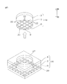
- FIG. 4 is a perspective view of the probe-containing sheet as viewed from below, and is a perspective view in which a part of the second release sheet is cut away.
- FIG. 5 is a perspective view for explaining the manufacturing process of the probe member, and the upper side view is a perspective view seen from the lower side, and the lower side view is a perspective view seen from the upper side.
- 6A to 6C are exploded perspective views of the probe member, and FIG. 6A shows the probe member, FIG. 6B shows the connection portion, and FIG. 6C shows the opening of one end in the longitudinal direction of the patch type biosensor.
- the conductive composition of the present invention contains a conductive polymer, a binder resin, and at least one of a crosslinking agent and a plasticizer.
- the conductive polymer can impart conductivity to the conductive composition (further, a conductive molded body described later).
- Examples of the conductive polymer include polythiophene compounds, polypyrrole compounds, polyaniline compounds (specifically, polyaniline and the like) and the like. These can be used alone or in combination of two or more.
- PEDOT-PSS polythiophene compound, more preferably (3,4-ethylenedioxythiophene) / poly (4-styrenesulfonic acid)
- PEDOT-PSS polythiophene compound
- excellent conductivity can be imparted to the conductive composition (further, the conductive molded body described later).
- the proportion of the conductive polymer is, for example, 1% by mass or more, preferably 5% by mass or more, and for example, 40% by mass or less, preferably 20% by mass or less, based on the conductive composition. is there.
- the ratio is equal to or more than the above-described lower limit, excellent conductivity can be imparted to the conductive composition (further, the conductive molded body described later).
- the ratio is equal to or less than the above-described upper limit, excellent toughness and flexibility can be imparted to the conductive composition (further, the conductive molded body described later).
- the binder resin can impart toughness to the conductive composition (further, the conductive molded body described later).
- the binder resin include water-soluble polymers and water-insoluble polymers.
- a water-soluble polymer is mentioned from the viewpoint of compatibility of other components in the conductive composition.
- the water-soluble polymer is not completely soluble in water, and includes a polymer having hydrophilicity (hydrophilic polymer).
- water-soluble polymer examples include a hydroxyl group-containing polymer.
- hydroxyl group-containing polymer examples include saccharides (such as agarose), for example, PVA, such as polymer poly (acrylic acid-sodium acrylate).
- PVA polymer poly (acrylic acid-sodium acrylate).
- PVA is mentioned. These can be used alone or in combination of two or more.
- polyvinyl alcohol for example, modified polyvinyl alcohol etc. are mentioned, for example.
- modified polyvinyl alcohol is mentioned.
- modified polyvinyl alcohol examples include acetoacetyl group-containing polyvinyl alcohol and diacetone acrylamide modified polyvinyl alcohol.
- acetoacetyl group-containing polyvinyl alcohol Preferably, an acetoacetyl group-containing polyvinyl alcohol is mentioned.
- Modified polyvinyl alcohol is described, for example, in JP-A-2016-166436.
- the proportion of the binder resin is, for example, 10% by mass or more, preferably 20% by mass or more, and for example, 50% by mass or less, preferably 35% by mass or less, based on the conductive composition.
- the ratio is equal to or more than the above-described lower limit, excellent toughness and flexibility can be imparted to the conductive composition (further, the conductive molded body described later). If the ratio is equal to or less than the above-described upper limit, excellent conductivity can be imparted to the conductive composition (further, the conductive molded body described later).
- the crosslinking agent and the plasticizer are a toughness / flexibility imparting agent that imparts toughness and flexibility to the conductive composition (further, the conductive molded body described later).
- toughness is a property which makes compatible the outstanding strength and the outstanding ductility. More specifically, one of the strength and the elongation is remarkably excellent, but the other does not include the remarkably low property, and includes the excellent property in the balance of both.
- the flexibility is a property capable of suppressing the occurrence of damage such as breakage in a bent portion (such as a fold) after bending (folding) a conductive molded body (a conductive sheet).
- the toughness / softening agent may contain at least one of a crosslinking agent and a plasticizer. That is, (1) the toughness / flexibility agent contains a crosslinking agent and does not contain a plasticizer, or (2) the toughness / flexibility agent contains a plasticizer and a crosslinking agent Does not contain
- both the toughness that is, both the tensile strength and the tensile elongation (compared to the comparative example (comparative example 1) in which the toughness / softening agent does not contain any of the crosslinking agent and the plasticizer) Improved).
- flexibility can be improved.
- the toughness / softening agent contains both a crosslinking agent and a plasticizer. If both the crosslinking agent and the plasticizer are contained in the conductive composition, even more excellent toughness can be imparted to the conductive composition (further, the conductive molded body described later).
- the crosslinking agent can crosslink the binder resin. This improves the toughness of the conductive composition to be imparted by the binder resin.
- the crosslinking agent has reactivity to react with a hydroxyl group if the binder resin is a hydroxyl group-containing polymer.
- a zirconium compound eg, zirconium salt etc.
- a titanium compound eg titanium salt etc.
- a boric acid compound eg boric acid etc.
- an alkoxy group-containing compound a methylol group
- isocyanate compounds for example, blocked isocyanate and the like
- aldehyde compounds for example, dialdehyde and the like such as glyoxal
- zirconium compounds, isocyanate compounds and aldehyde compounds are mentioned.
- the proportion of the crosslinking agent is, for example, 1 part by mass or more, preferably 10 parts by mass or more, and for example, 50 parts by mass or less, preferably 25 parts by mass or less with respect to 100 parts by mass of the binder resin. . If the ratio is at least the lower limit described above and the upper limit described above, it is possible to impart excellent toughness and excellent flexibility to the conductive composition (further, the conductive molded body described later).
- the plasticizer plasticizes the conductive polymer.
- the plasticizer improves the tensile elongation and flexibility of the conductive composition.
- the plasticizer for example, polyol compounds such as glycerin, ethylene glycol, propylene glycol, sorbitol, their polymers, etc., for example, N-methylpyrrolidone (NMP), dimethylformamide (DMF), N, N'-dimethylacetamide ( DMAc), aprotic compounds such as dimethyl sulfoxide (DMSO), and the like. These can be used alone or in combination of two or more.
- a polyol compound is mentioned from the viewpoint of compatibility with other components.
- the proportion of the plasticizer is, for example, 100 parts by mass or more, preferably 300 parts by mass or more, and for example, 1000 parts by mass or less, preferably 600 parts by mass or less with respect to 100 parts by mass of the conductive polymer. It is.
- the proportion of the plasticizer is equal to or more than the above-described lower limit, excellent flexibility can be reliably imparted to the conductive composition (further, the conductive molded body described later). If the proportion of the plasticizer is equal to or less than the above-described upper limit, excellent toughness and excellent flexibility can be imparted to the conductive composition (further, the conductive molded body described later).
- additives such as surfactant
- surfactant silicone type surfactant etc. are mentioned, for example.
- the above-described components are blended in the above-described proportions and mixed.
- a solvent is used in an appropriate ratio.
- the solvent include organic solvents, for example, aqueous solvents such as water.
- aqueous solvent is mentioned.
- the conductive polymer and / or the binder resin preferably, a water-soluble polymer
- the conductive composition is prepared (prepared) as a conductive composition liquid (conductive composition aqueous solution).
- a conductive molded body such as a conductive sheet is prepared from the conductive composition.
- the conductive composition liquid is applied to the surface of a substrate (release sheet, pan, etc.) and then dried to remove the solvent.
- the conductive molded body is molded as a conductive sheet.
- the conductive molded body is further heat-treated.
- the conditions of the heat treatment are conditions under which the crosslinking agent can react.
- the conductive molded body is, for example, 100 ° C. or more, preferably 120 ° C. or more, for example, 180 ° C. or less, preferably 160 ° C. or less, for example, 5 minutes or more, preferably For 15 minutes or more, for example, 300 minutes or less, preferably 120 minutes or less.
- a conductive molded body (conductive sheet) is thus obtained.
- the conductive molded body is rubbery and has both toughness and flexibility.
- the volume resistivity of the conductive molded body is, for example, 1 ⁇ 10 ⁇ 2 ⁇ ⁇ m or less, preferably 5 ⁇ 10 ⁇ 3 ⁇ ⁇ m or less.
- the method of measuring the volume resistivity is described in the examples below.
- the toughness of the conductive molded body (conductive sheet) is evaluated in both tensile strength and tensile elongation.
- the tensile strength of the conductive molded body (conductive sheet) is, for example, 2 N / m 2 or more, preferably 5 N / m 2 or more.
- the tensile elongation of the conductive molded body (conductive sheet) is, for example, 10% or more, preferably 50% or more.
- Specific toughness is, for example, (1) tensile strength of 2 N / m 2 or more and tensile elongation of 50% or more, for example (2) tensile strength of 5 N / m 2 or more, and tensile elongation of 10 % Or more. If at least one of (1) and (2) is satisfied, the conductive green body (conductive sheet) has toughness (excellent toughness).
- More preferable toughness is (3) a tensile strength of 5 N / m 2 or more and a tensile elongation of 50% or more.
- the softness is evaluated, for example, in a two-fold test, and the breaking rate is, for example, less than 50%, preferably less than 20%.
- this electroconductive composition contains at least any one of a crosslinking agent and a plasticizer, it can prepare the electroconductive molded object which is excellent in toughness and flexibility.
- the application of the conductive molded body can be applied to various applications where toughness and flexibility are required, for example, biological applications, clothes, fashion type sensor applications and the like.
- the left-right direction in the drawing is the longitudinal direction (first direction) of the adhesive biosensor 30.
- the right side in the drawing is one side in the longitudinal direction (one side in the first direction), and the left side in the drawing is the other side in the longitudinal direction (the other side in the first direction).
- the vertical direction in the drawing is the short side direction (a direction perpendicular to the longitudinal direction, a width direction, and a second direction orthogonal to the first direction) of the adhesive biosensor 30.
- the upper side of the drawing is one side in the lateral direction (one side in the width direction, one side in the second direction), and the lower side in the drawing is the other side in the lateral direction (the other side in the width direction, the other side in the second direction).
- the paper thickness direction is the vertical direction (the thickness direction, the first direction, and the third direction orthogonal to the second direction) of the adhesive biosensor 30.
- the paper front side is the upper side (one side in the thickness direction, one side in the third direction), and the back side in the paper is the lower side (the other side in the thickness direction, the other side in the third direction).
- the direction conforms to the direction arrow described in each drawing.
- the stick-type biosensor 30 has a substantially flat plate shape extending in the longitudinal direction.
- the patch-type biosensor 30 is a sheet having excellent toughness and flexibility.
- the pressure-sensitive adhesive layer 2 includes the pressure-sensitive adhesive layer 2, the base material layer 3 disposed on the adhesion upper surface of the pressure-sensitive adhesive layer 2, the wiring layer 4 disposed on the base material layer 3, and the pressure-sensitive adhesive layer 2.
- the connection portion 6 as an example of the conductive molded body for electrically connecting the probe 5 disposed on the adhesive lower surface 9 of the wiring layer 4 and the probe 5, and the electronic component 31 electrically connected to the wiring layer 4 And
- the pressure sensitive adhesive layer 2 forms the lower surface of the adhesive type biosensor 30.
- the pressure-sensitive adhesive layer 2 is a layer that imparts pressure-sensitive adhesiveness to the lower surface of the patch-type biosensor 30 in order to stick the lower surface of the patch-type biosensor 30 to the surface of the living body (such as the skin 33 shown by imaginary lines). It is.
- the pressure sensitive adhesive layer 2 forms the outer shape of the adhesive type biosensor 30.
- the pressure sensitive adhesive layer 2 has a flat plate shape extending in the longitudinal direction. Specifically, for example, the pressure-sensitive adhesive layer 2 has a strip extending in the longitudinal direction, and has a shape in which the longitudinal central portion bulges outward in the lateral direction. Further, in the pressure-sensitive adhesive layer 2, both shortwise end edges of the longitudinal central portion are located on both lateral outer sides with respect to short directional end edges other than the longitudinal central portion.
- the pressure sensitive adhesive layer 2 has an adhesive upper surface 8 and an adhesive lower surface 9.
- the adhesion upper surface 8 is a flat surface.
- the adhesive lower surface 9 is disposed opposite to the lower side of the adhesive upper surface 8 with a space.
- the pressure-sensitive adhesive layer 2 has each of the two adhesion openings 11 in each of the longitudinal direction both ends.
- Each of the two bonding openings 11 has a substantially ring shape in plan view.
- the adhesion opening 11 penetrates the thickness direction of the pressure sensitive adhesive layer 2.
- the bonding openings 11 are filled with the connection 6.
- the adhesion lower surface 9 inside the adhesion opening 11 has an adhesion groove 10 corresponding to the probe 5 (described later).
- the bonding groove 10 is opened downward.
- the material of the pressure-sensitive adhesive layer 2 is not particularly limited as long as it is a material having pressure-sensitive adhesiveness, for example.
- the base material layer 3 forms the upper surface of the sticking type biosensor 30 together with an electronic component 31 described later.
- the base material layer 3 and the pressure-sensitive adhesive layer 2 form the outer shape of the sticking type biosensor 30.
- the plan view shape of the base material layer 3 is the same as the plan view shape of the pressure sensitive adhesive layer 2.
- the base material layer 3 is disposed on the entire upper surface of the pressure-sensitive adhesive layer 2 (except for the region where the connection portion 6 is provided).
- the base layer 3 is a support layer that supports the pressure-sensitive adhesive layer 2.
- the base layer 3 has a flat plate shape extending in the longitudinal direction.
- the base layer 3 has a base lower surface 12 and a base upper surface 13.
- the substrate lower surface 12 is a flat surface.
- the substrate lower surface 12 is in contact (pressure-sensitive adhesion) with the adhesive upper surface 8 of the pressure-sensitive adhesive layer 2.
- the upper substrate surface 13 is disposed to face the upper surface of the lower substrate surface 12 at a distance.
- the substrate upper surface 13 has a substrate groove 14 corresponding to the wiring layer 4.
- the base material groove 14 has the same pattern shape as the wiring layer 4 in a plan view.
- the base groove 14 is opened upward.
- the base material layer 3 also has a base material opening 15 corresponding to the bonding opening 11.
- the base material opening 15 communicates with the bonding opening 11 in the thickness direction.
- the base opening 15 has a substantially ring shape in plan view having the same shape and the same size as the bonding opening 11.
- the material of the base layer 3 has, for example, stretchability. Moreover, the material of the base material layer 3 has an insulating layer, for example. Examples of such a material include resins such as polyurethane resins.
- the breaking elongation of the base material layer 3 is, for example, 100% or more, preferably 200% or more, more preferably 300% or more. Also, for example, 2000% or less. If the breaking elongation is equal to or more than the above lower limit, the material of the base material layer 3 can have excellent stretchability.
- the wiring layer 4 is embedded in the base material groove 14, for example. Specifically, the wiring layer 4 is embedded in the upper portion of the base layer 3 so as to be exposed from the upper surface 13 of the base layer 3.
- Wiring layer 4 has upper and lower surfaces spaced from each other, and side surfaces connecting the peripheral edges thereof. All of the lower surface and all of the side surfaces are in contact with the substrate layer 3. The upper surface is exposed from the substrate upper surface 13 (except for the substrate groove 14).
- the upper surface of the wiring layer 4 forms the upper surface of the adhesive biosensor 30 together with the upper surface 13 of the base and the electronic component 31.
- the wiring layer 4 has a wiring pattern for connecting the connection portion 6 to the electronic component 31 (described later) and the battery 32 (described later). Specifically, the wiring layer 4 includes the first wiring pattern 41 and the second wiring pattern 42 independently.
- the first wiring pattern 41 is disposed on one side in the longitudinal direction of the base material layer 3.
- the first wiring pattern 41 includes a first wiring 16A, and a first terminal 17A and a second terminal 17B continuous to the first wiring 16A.
- the first wiring pattern 41 has a substantially T-shape in plan view. Specifically, the first wiring pattern 41 extends from the (longitudinal one end portion of the base material layer 3) to the other side in the longitudinal direction and is branched at the longitudinal central portion of the base material layer 3. , Extend in the lateral direction both outwards.
- Each of the first terminal 17A and the second terminal 17B is disposed at each of both ends in the lateral direction at the central portion in the longitudinal direction of the base material layer 3.
- Each of the first terminal 17A and the second terminal 17B has a substantially rectangular shape (land shape) in plan view.
- Each of the first terminal 17A and the second terminal 17B is continuous with each of both end portions of the first wiring 16A extending outward in the lateral direction at the central portion in the longitudinal direction of the base material layer 3.
- the second wiring pattern 42 is provided on the other side in the longitudinal direction of the first wiring pattern 41 at an interval.
- the second wiring pattern 42 includes a second wiring 16B, and a third terminal 17C and a fourth terminal 17D continuous to the second wiring 16B.
- the second wiring pattern 42 has a substantially T-shape in plan view. Specifically, the second wiring pattern 42 extends from the other end of the base layer 3 in the longitudinal direction (the connecting portion 6 located on the other side) toward one side in the longitudinal direction, and branches at the longitudinal center of the base layer 3 And extend outward in the lateral direction.
- Each of the third terminal 17 ⁇ / b> C and the fourth terminal 17 ⁇ / b> D is disposed at each of both ends in the lateral direction at the central portion in the longitudinal direction of the base material layer 3.
- Each of the third terminal 17C and the fourth terminal 17D has a substantially rectangular shape (land shape) in plan view.
- Each of the third terminal 17C and the fourth terminal 17D is continuous with each of the two end portions of the second wiring 16B extending outward in the lateral direction at the central portion in the longitudinal direction of the base material layer 3.
- Examples of the material of the wiring layer 4 include conductors such as copper, nickel, gold, and alloys thereof. Preferably, copper is mentioned as a material of the wiring layer 4.
- the probe 5 is an electrode that contacts the skin 33 when the pressure-sensitive adhesive layer 2 is attached to the skin 33 and senses an electrical signal from the living body, temperature, vibration, sweat, a metabolite, and the like.
- the probe 5 is embedded in the pressure sensitive adhesive layer 2 so as to be exposed from the adhesive lower surface 9 of the pressure sensitive adhesive layer 2. That is, the probe 5 is embedded in the bonding groove 10 in the pressure-sensitive adhesive layer 2 inside the bonding opening 11.
- the probe 5 is disposed on the adhesive lower surface 9 forming the adhesive groove 10. In short, the probe 5 is embedded in the lower end portion of the pressure sensitive adhesive layer 2 inside the adhesive opening 11.
- the probe 5 has a net shape, preferably a substantially grid shape in plan view (or a substantially mesh shape). In other words, the probe 5 has holes spaced apart from each other in the surface direction (longitudinal direction and short side direction).
- the pressure-sensitive adhesive layer 2 is filled in the holes.
- the probe 5 has a substantially rectangular shape in a cross-sectional view orthogonal to the direction in which it extends.
- the probe 5 has a probe lower surface 20, a probe upper surface 21 opposed to the upper side of the probe lower surface 20 at a distance, and side surfaces connecting peripheral edges of the probe lower surface 20 and the probe upper surface 21.
- the probe lower surface 20 is exposed from the adhesive lower surface 9 (except for the adhesive groove 10) of the pressure-sensitive adhesive layer 2.
- the probe lower surface 20 is flush with the bonding lower surface 9.
- the probe lower surface 20 forms the lower surface of the adhesive type biosensor 30 together with the adhesive lower surface 9.
- the upper surface 21 and the side surfaces of the probe are coated with the pressure sensitive adhesive layer 2.
- the outermost surface of the side surfaces of the probe 5 is the outer surface 22.
- the outer side surface 22 forms an imaginary circle passing through the outer side surface 22 in a plan view.
- Examples of the material of the probe 5 include the materials (specifically, conductors) exemplified for the wiring layer 4.
- the outer dimensions of the probe 5 are set such that an imaginary circle passing through the outer side surface 22 is overlapped in plan view with the inner circumferential surface defining the bonding opening 11.
- connection part 6 is an example of the electroconductive molded object prepared and shape
- the connection portion 6 is provided corresponding to the base material opening 15 and the bonding opening 11 and has the same shape as them.
- the connection portion 6 penetrates (passes) the base material layer 3 and the pressure-sensitive adhesive layer 2 in the thickness direction (vertical direction), and is filled in the base material opening 15 and the bonding opening 11.
- the connection portion 6 has an endless shape in plan view along the outer side surface 22 of the probe 5. Specifically, the connection portion 6 has a substantially cylindrical shape whose axis extends in the thickness direction (along an imaginary circle passing through the outer side surface 22).
- connection portion 6 is in contact with the outer surface 22 of the probe 5.
- the connecting portion 6 is pressure-sensitively adhered to the pressure-sensitive adhesive layer 2 outside the adhesive opening 11 and the pressure-sensitive adhesive layer 2 inside the adhesive opening 11.
- the connecting portion 6 is in contact with the base material layer 3 outside the base material opening 15 and the base material layer 3 inside the base material opening 15.
- connection portion 6 is flush with the upper surface 13 of the base.
- the lower surface of the connection portion 6 is flush with the adhesive lower surface 9.
- connection portion 6 located on one side in the longitudinal direction is continuous with one end edge in the longitudinal direction of the wiring 16 ⁇ / b> A located on the one side in the longitudinal direction.
- the connection portion 6 located on the other side in the longitudinal direction is continuous at the upper end portion with the other end edge in the longitudinal direction of the wire 16B located on the other side in the longitudinal direction.
- connection portion 6 is electrically connected to the wiring layer 4.
- connection portion 6 electrically connects the wiring layer 4 and the probe 5.
- connection portion 6 and the wiring layer 4 constitute a circuit portion 36 which electrically connects the probe 5 to the electronic component 31. That is, the circuit portion 36 includes the wiring layer 4 disposed on the base upper surface 13 of the base layer 3 and the connection portion 6 passing through the base layer 3 and the pressure sensitive adhesive layer 2. Preferably, the circuit unit 36 consists only of the wiring layer 4 and the connection portion 6.
- the radial length (half value of the value obtained by subtracting the inner diameter from the outer diameter) of the connection portion 6 is, for example, 1 ⁇ m or more, preferably 100 ⁇ m or more, and for example, less than 2000 ⁇ m, preferably 1000 ⁇ m or less, more preferably Is less than 500 ⁇ m.
- Communication ICs for wireless transmission to devices, transmitters, etc. may be mentioned.
- the patch type biosensor 30 is a patch type electrocardiograph
- the potential change of the heart acquired by the probe 5 is converted to digital data by the analog front end, and the potential change of the heart is stored in the memory. Record.
- the change in heart potential is recorded in a memory at a data rate of 16 bits and 1 kHz. In order to reduce the size of memory, data resolution and data rate may be reduced.
- the recorded data is analyzed by taking out data from the memory after removing the adhesive biosensor 30 after measurement.
- the communication IC also has a function of wirelessly transmitting the signal acquired by the probe 5 to the outside.
- the electronic component 31 may have part or all of the above.
- the electronic component 31 is in contact with the upper surface 13 of the substrate.
- the electronic component 31 has a substantially rectangular shape in cross section.
- Two terminals 35 are provided on the lower surface of the electronic component 31.
- Each of the two terminals 35 of the electronic component 31 is electrically connected to each of the first terminal 17A and the third terminal 17C.
- the electronic component 31 is harder than, for example, the pressure-sensitive adhesive layer 2 and the base material layer 3.
- the base material layer 3 and the wiring layer 4 are prepared.
- the base material layer 3 and the wiring layer 4 are prepared such that the wiring layer 4 is embedded in the base material groove 14 by the method described in Japanese Patent Application Laid-Open Nos. 2017-22236 and 2017-22237.
- the pressure-sensitive adhesive layer 2 is disposed on the lower surface 12 of the substrate.
- the pressure-sensitive adhesive layer 2 In order to dispose the pressure-sensitive adhesive layer 2 on the lower surface 12 of the substrate, for example, first, a coating solution containing the material of the pressure-sensitive adhesive layer 2 is prepared, and then the coating solution is applied to the upper surface of the first release sheet 19 Apply and then dry by heating. Thereby, the pressure-sensitive adhesive layer 2 is disposed on the upper surface of the first release sheet 19.
- the first release sheet 19 has, for example, a substantially flat plate shape extending in the longitudinal direction. Examples of the material of the first release sheet 19 include resins such as polyethylene terephthalate.
- the pressure-sensitive adhesive layer 2 and the base material layer 3 are attached to each other by, for example, a laminator. Specifically, the adhesive upper surface 8 of the pressure-sensitive adhesive layer 2 and the substrate lower surface 12 of the substrate layer 3 are brought into contact with each other.
- each of the base material layer 3 and the pressure-sensitive adhesive layer 2 does not have each of the base material opening 15 and the bonding opening 11.
- the openings 23 are formed in the base layer 3 and the pressure-sensitive adhesive layer 2.
- the opening 23 penetrates the base layer 3 and the pressure-sensitive adhesive layer 2.
- the opening 23 is a hole (through hole) having a substantially circular shape in plan view, which is divided by the outer peripheral surface that divides the base material opening 15 and the outer peripheral surface that divides the bonding opening 11.
- the opening 23 is opened upward.
- the lower end of the opening 23 is closed by the first release sheet 19.
- the pressure-sensitive adhesive layer 2 and the base material layer 3 are punched and half-etched, for example.
- the probe member 18 is then prepared and fitted into the opening 23.
- the probe-containing sheet 26 is prepared.
- the probe-containing sheet 26 is formed on the second release sheet 29, the probe pattern 25 formed on the second release sheet 29, and the pressure-sensitive adhesive layer 2 formed on the second release sheet 29 to embed the probe pattern 25. And the base material layer 3 disposed on the adhesive upper surface 8 of the pressure-sensitive adhesive layer 2.
- the second release sheet 29 has the same configuration as the first release sheet 19 described above.
- the probe pattern 25 has the same pattern shape as the probe 5, and the material of the probe pattern 25 is the same as the material of the probe 5.
- the probe pattern 25 has a plane area larger than an imaginary circle passing through the outer surface 22 of the probe 5.
- Each of the pressure sensitive adhesive layer 2 and the base material layer 3 in the probe-containing sheet 26 has the same configuration as each of the pressure sensitive adhesive layer 2 and the base material layer 3 described above.
- the probe-containing sheet 26 is prepared, for example, by the methods described in JP-A-2017-22236 and JP-A-2017-22237.
- a seed layer made of copper is formed on the upper surface of the release layer made of stainless steel, and then a photoresist is laminated on the entire upper surface of the seed layer. The photoresist is then exposed and developed to form the photoresist in the reverse of the probe pattern 25. Subsequently, after the probe pattern 25 is formed on the upper surface of the seed layer by electrolytic plating, the photoresist is removed. Thereafter, a coating solution containing the material of the pressure sensitive adhesive layer 2 is applied so as to cover the probe pattern 25 and cured to form the pressure sensitive adhesive layer 2. Next, the base material layer 3 is attached to the upper surface of the pressure-sensitive adhesive layer 2 by, for example, a laminator. Then, the peeling layer is peeled from the lower surface of the seed layer, and subsequently, the seed layer is removed. Then, the 2nd peeling sheet 29 is bonded together to the lower surface of the pressure sensitive adhesive layer 2 as needed.
- the probe-containing sheet 26 is thus prepared.
- the cutting lines 27 are formed on the probe pattern 25, the pressure-sensitive adhesive layer 2 and the base layer 3 in a substantially circular shape in plan view.
- the cutting line 27 is formed by, for example, punching.
- the cutting line 27 divides the probe pattern 25, the pressure-sensitive adhesive layer 2 and the base layer 3 into the inside and outside thereof, but is not formed on the second release sheet 29.
- the dimensions of the cutting line 27 are the same as the inner diameters of the bonding opening 11 and the base opening 15. That is, the cutting line 27 coincides with an imaginary circle passing through the outer side surface 22.
- the formation of the cutting line 27 forms the probe member 18.
- the outer side surface 22 of the probe 5 is flush with the outer side surface of the pressure sensitive adhesive layer 2. Further, in the probe member 18, the outer side surface 22 is exposed radially outward from the outer side surface of the pressure-sensitive adhesive layer 2.
- the probe member 18 is pulled up from the second release sheet 29. Specifically, the adhesive lower surface 9 and the probe lower surface 20 of the probe member 18 are peeled off from the second release sheet 29.
- the probe member 18 is fitted into the opening 23.
- connection portion 6 is provided in the base material opening 15 and the bonding opening 11.
- a conductive resin composition (conductive composition liquid) is injected (or applied) to the base opening 15 and the bonding opening 11. Thereafter, the conductive resin composition (conductive composition liquid) is heated to remove the solvent, and at the same time, the binder resin is crosslinked by the crosslinking agent.
- the laminated body 1 for biosensors provided with the 1st peeling sheet 19, the pressure sensitive adhesive layer 2, the base material layer 3, the wiring layer 4, the probe 5, and the connection part 6 is produced.
- the laminated body 1 for biometrics distribute
- the biosensor stack 1 can be circulated independently, separately from the electronic component 31 and the battery 32 (see the phantom line in FIG. 1) described below. That is, the laminate 1 for a biosensor is a component for manufacturing the adhesive type biosensor 30 without mounting the electronic component 31 and the battery 32.
- each of the two terminals 35 of the electronic component 31 is electrically connected to each of the first terminal 17A and the third terminal 17C.
- the lower surface of the electronic component 31 is brought into contact with the upper surface 13 of the base.
- the adhesive type biosensor 30 preferably includes the pressure-sensitive adhesive layer 2, the base layer 3, the wiring layer 4, the probe 5, the connection portion 6, the electronic component 31, and the first peeling sheet 19. Consists only of them. As shown in FIG. 2A, the adhesive type biosensor 30 does not include the first release sheet 19, and the pressure-sensitive adhesive layer 2, the base layer 3, the wiring layer 4, the probe 5, and the connection portion 6. And the electronic component 31 may be included.
- the battery 32 is mounted on the adhesive type biosensor 30.
- the battery 32 has a substantially flat (box) shape extending in the surface direction.
- the battery 32 has two terminals (not shown) provided on its lower surface.
- two terminals (not shown) of the battery 32 are electrically connected to the second terminal 17B and the fourth terminal 17D, respectively. At this time, the lower surface of the battery 32 is brought into contact with the upper surface 13 of the substrate.
- the first release sheet 19 (see arrow and phantom line in FIG. 3D) is removed from the pressure-sensitive adhesive layer 2 and the probe 5.
- the adhesive lower surface 9 of the pressure sensitive adhesive layer 2 is brought into contact with, for example, the skin 33 of the human body. Specifically, the pressure-sensitive adhesive layer 2 is pressure-sensitively adhered to the surface of the skin 33.
- the probe lower surface 20 of the probe 5 comes in contact with the surface of the skin 33 by pressure-sensitive adhesion (pasting) of the adhesive lower surface 9 to the skin 33.
- the probe 5 senses as an electrical signal from the living body, and the electrical signal sensed by the probe 5 is input to the electronic component 31 through the connection portion 6 and the wiring layer 4.
- the electronic component 31 processes the electrical signal based on the power supplied from the battery 32 and stores it as information. Furthermore, if necessary, the electric signal is converted into a radio wave, which is wirelessly transmitted to an external receiver.
- the patch-type biosensor 30 may be, for example, a device capable of monitoring the state of a living body by sensing an electrical signal from the living body, and more specifically, a patch-type electrocardiograph, a patch-type electroencephalograph, a patch-type blood pressure And a pulse-type pulse meter, a patch-type electromyograph, a patch-type thermometer, and a patch-type accelerometer. Also, these devices may be individual devices or a plurality of devices may be incorporated in one device.
- the patch-type biosensor 30 is preferably used as a patch-type electrocardiograph.
- the probe 5 senses the action potential of the heart as an electrical signal.
- a living body includes living bodies other than a human body and a human body, Preferably, it is a human body.
- connection portion 6 is prepared from the above-described conductive composition, the contraction of the skin 33 is flexibly followed, and the durability is also excellent. Therefore, in the attachment type biosensor 30, the connection reliability by the connection portion 6 is excellent, and the reliability of sensing is excellent.
- connection portion 6 has a cylindrical shape, but the shape is not particularly limited, and may have, for example, a rectangular cylindrical shape.
- blending ratios content ratios
- physical property values parameters, etc. used in the following description are the blending ratios (content ratios) corresponding to those described in the above-mentioned “embodiments for carrying out the invention” ), Physical property values, parameters, etc. may be substituted for the upper limit (numerical values defined as “below”, “less than”) or lower limit (numerical values defined as “above”, “exceed”), etc. it can.
- PH1000 trade name "Clevious PH1000", PEDOT-PSS (conductive polymer) aqueous solution, manufactured by Heraeus Goosenex Z-410: 10% aqueous solution of modified polyvinyl alcohol (acetoacetyl group-containing polyvinyl alcohol), Nippon Synthetic Chemical Co., Ltd.
- Kranol Modified polyvinyl alcohol (acetoacetyl group-containing polyvinyl alcohol) 10% aqueous solution Safe ring SPM-01: 10% aqueous solution of crosslinker (zirconium compound), manufactured by Nippon Gohsei Chemical Co., Ltd. SU-268A: Meisei Chemical Industry Co., Ltd.
- polyethylene glycol 600 Polyethylene glycol with a number average molecular weight of 570 to 630
- Silface SAG 503A silicone surfactant, manufactured by Nisshin Chemical Industry Co., Ltd.
- Example 1 PEDOT-PSS (conductive polymer) aqueous solution (Clevious PH1000, manufactured by Heraeus) 19.0 g, modified polyvinyl alcohol) (Gosenex Z-410, manufactured by Japan Synthetic Chemical Co., Ltd.) 10% aqueous solution 5.0 g, crosslinker (zirconium compound ) Of a 10% aqueous solution (Safeling SPM-01, manufactured by Nippon Synthetic Chemical Co., Ltd.), 1.0 g of a plasticizer (glycerin, manufactured by Wako Pure Chemical Industries, Ltd.), surfactant (Silface SAG 503A, Nisshin Chemical Industry Co., Ltd.) ) And mixed in an ultrasonic bath for 30 minutes to prepare a uniform aqueous solution of the conductive composition.
- a plasticizer glycerin, manufactured by Wako Pure Chemical Industries, Ltd.
- surfactant Surfactant
- an aqueous solution of the conductive composition is coated on a PET (polyethylene terephthalate) film using an applicator, and then dried by heating in a drying oven at 90 ° C. for 30 minutes, followed by 120 ° C., 15 It was heated for a minute and crosslinked to form a conductive sheet (prepared).
- the conductive sheet was bluish black flexible rubber-like.
- Example 2 to Comparative Example 1 It processed similarly to Example 1 except having changed the combination of each component according to Table 1, and shape
- the conductive sheet was subjected to a tensile test under the following conditions to calculate tensile strength and tensile elongation based on the stress value at break.
- Equipment Tensiron universal material testing machine (A & D RTF) Size: 5 mm width, thickness 20 ⁇ m Chuck distance: 10 mm
- each of tensile strength and tensile elongation was evaluated according to the following reference
- the breaking ratio at the time of folding the conductive sheet in two (for example, if 10 out of 10 conductive sheets are broken, the breaking ratio is 20%) is determined, and the flexibility is determined based on the following: evaluated. ⁇ : Failure rate less than 20% ⁇ : Failure rate 20% or more, less than 50% ⁇ : Fracture rate 50% or more
- the conductive composition is used for the connection portion of the biological sensor.
Abstract
A conductive composition according to the present invention contains a conductive polymer, a binder resin, and at least one of a crosslinking agent and a plasticizer.
Description
本発明は、導電性組成物および生体センサに関する。
The present invention relates to a conductive composition and a biological sensor.
導電性組成物として、ポリ(3,4-エチレンジオキシチオフェン):ポリ(スチレンスルホネート)(PEDOT-PSS)と、ポリビニルアルコール(PVA)との混合物が知られている(例えば、非特許文献1参照。)。
As a conductive composition, a mixture of poly (3,4-ethylenedioxythiophene): poly (styrene sulfonate) (PEDOT-PSS) and polyvinyl alcohol (PVA) is known (for example, Non-Patent Document 1) reference.).
この混合物は、導電性および成形性に優れており、そして、この混合物から形成された導電性成形体(導電性フィルム)は、優れた耐久性、靱性、可撓性を有する。
This mixture is excellent in conductivity and moldability, and a conductive molded body (conductive film) formed from the mixture has excellent durability, toughness and flexibility.
しかるに、導電性成形体には、より一層優れた強靱性(具体的には、引張強度および引張伸度(伸び)の両立)と、柔軟性とが求められる場合がある。
However, the conductive molded body may be required to have even more excellent toughness (specifically, compatibility between tensile strength and tensile elongation (elongation)) and flexibility.
本発明は、強靱性および柔軟性に優れる導電性成形体を調製することのできる導電性組成物、および、導電性組成物から調製される接続部を備える生体センサを提供する。
The present invention provides a conductive composition capable of preparing a conductive molded article excellent in toughness and flexibility, and a biological sensor provided with a connection prepared from the conductive composition.
本発明(1)は、導電性高分子と、バインダー樹脂と、架橋剤および可塑剤のうち少なくともいずれか一方とを含有する、導電性組成物を含む。
The present invention (1) includes a conductive composition containing a conductive polymer, a binder resin, and at least one of a crosslinking agent and a plasticizer.
本発明(2)は、前記架橋剤および前記可塑剤の両方を含有する、(1)に記載の導電性組成物を含む。
This invention (2) contains the electroconductive composition as described in (1) which contains both the said crosslinking agent and the said plasticizer.
本発明(3)は、前記バインダー樹脂が、水溶性高分子である、(1)または(2)に記載の導電性組成物を含む。
This invention (3) contains the electroconductive composition as described in (1) or (2) whose said binder resin is water-soluble polymer.
本発明(4)は、前記架橋剤が、ジルコニウム化合物、イソシアネート化合物およびアルデヒド化合物からなる群から選択される少なくともいずれか1つを含有する、(1)~(3)のいずれか一項に記載の導電性組成物を含む。
The present invention (4) is described in any one of (1) to (3), wherein the crosslinking agent contains at least one selected from the group consisting of a zirconium compound, an isocyanate compound and an aldehyde compound. The conductive composition of
本発明(5)は、前記可塑剤が、ポリオール化合物を含有する、(1)~(4)のいずれか一項に記載の導電性組成物を含む。
The invention (5) includes the conductive composition according to any one of (1) to (4), wherein the plasticizer contains a polyol compound.
本発明(6)は、配線層と、生体表面に接触するプローブと、前記配線層および前記プローブを電気的に接続する接続部とを備え、前記接続部は、(1)~(5)のいずれか一項に記載の導電性組成物から調製される接続部を備える、生体センサを含む。
The present invention (6) comprises a wiring layer, a probe in contact with the surface of a living body, and a connection portion for electrically connecting the wiring layer and the probe, wherein the connection portion is any one of (1) to (5) It includes a bio-sensor comprising a connection prepared from the conductive composition according to any one of the preceding claims.
本発明の導電性組成物は、架橋剤および可塑剤のうち少なくともいずれか一方を含有するので、強靱性および柔軟性に優れる導電性成形体を調製することができる。
Since the conductive composition of the present invention contains at least one of a crosslinking agent and a plasticizer, a conductive molded body having excellent toughness and flexibility can be prepared.
本発明の生体センサは、接続信頼性に優れる。
The biological sensor of the present invention is excellent in connection reliability.
[導電性組成物]
本発明の導電性組成物は、導電性高分子と、バインダー樹脂と、架橋剤および可塑剤のうち少なくともいずれか一方とを含有する。 [Conductive composition]
The conductive composition of the present invention contains a conductive polymer, a binder resin, and at least one of a crosslinking agent and a plasticizer.
本発明の導電性組成物は、導電性高分子と、バインダー樹脂と、架橋剤および可塑剤のうち少なくともいずれか一方とを含有する。 [Conductive composition]
The conductive composition of the present invention contains a conductive polymer, a binder resin, and at least one of a crosslinking agent and a plasticizer.
[各成分]
導電性高分子は、導電性を導電性組成物(さらには、後述する導電性成形体)に付与することができる。導電性高分子としては、例えば、ポリチオフェン化合物、ポリピロール化合物、ポリアニリン化合物(具体的には、ポリアニリンなど)などが挙げられる。これらは、単独使用または2種以上併用することができる。 [Each ingredient]
The conductive polymer can impart conductivity to the conductive composition (further, a conductive molded body described later). Examples of the conductive polymer include polythiophene compounds, polypyrrole compounds, polyaniline compounds (specifically, polyaniline and the like) and the like. These can be used alone or in combination of two or more.
好ましくは、ポリチオフェン化合物、より好ましくは、(3、4-エチレンジオキシチオフェン)/ポリ(4-スチレンスルホン酸)(以下、PEDOT-PSS)と称することがある。)が挙げられる。PEDOT-PSSであれば、優れた導電性を導電性組成物(さらには、後述する導電性成形体)に付与することができる。
Preferably, it may be referred to as a polythiophene compound, more preferably (3,4-ethylenedioxythiophene) / poly (4-styrenesulfonic acid) (hereinafter referred to as PEDOT-PSS). Can be mentioned. With PEDOT-PSS, excellent conductivity can be imparted to the conductive composition (further, the conductive molded body described later).
導電性高分子の割合は、導電性組成物に対して、例えば、1質量%以上、好ましくは、5質量%以上であり、また、例えば、40質量%以下、好ましくは、20質量%以下である。割合が上記した下限以上であれば、導電性組成物(さらには、後述する導電性成形体)に優れた導電性を付与することができる。割合が上記した上限以下であれば、導電性組成物(さらには、後述する導電性成形体)に優れた強靱性および柔軟性を付与することができる。
The proportion of the conductive polymer is, for example, 1% by mass or more, preferably 5% by mass or more, and for example, 40% by mass or less, preferably 20% by mass or less, based on the conductive composition. is there. When the ratio is equal to or more than the above-described lower limit, excellent conductivity can be imparted to the conductive composition (further, the conductive molded body described later). When the ratio is equal to or less than the above-described upper limit, excellent toughness and flexibility can be imparted to the conductive composition (further, the conductive molded body described later).
バインダー樹脂は、強靱性を導電性組成物(さらには、後述する導電性成形体)に付与することができる。バインダー樹脂としては、例えば、水溶性高分子、水不溶性高分子が挙げられる。好ましくは、導電性組成物における他の成分の相溶性の観点から、水溶性高分子が挙げられる。なお、水溶性高分子は、水に完全には溶けず、親水性を有する高分子(親水性高分子)を含む。
The binder resin can impart toughness to the conductive composition (further, the conductive molded body described later). Examples of the binder resin include water-soluble polymers and water-insoluble polymers. Preferably, a water-soluble polymer is mentioned from the viewpoint of compatibility of other components in the conductive composition. The water-soluble polymer is not completely soluble in water, and includes a polymer having hydrophilicity (hydrophilic polymer).
水溶性高分子としては、例えば、ヒドロキシル基含有高分子が挙げられる。ヒドロキシル基含有高分子として、例えば、糖類(アガロースなど)、例えば、PVA、例えば、高分子ポリ(アクリル酸-アクリル酸ナトリウム)などが挙げられる。好ましくは、PVAが挙げられる。これらは、単独使用または2種以上併用することができる。
Examples of the water-soluble polymer include a hydroxyl group-containing polymer. Examples of the hydroxyl group-containing polymer include saccharides (such as agarose), for example, PVA, such as polymer poly (acrylic acid-sodium acrylate). Preferably, PVA is mentioned. These can be used alone or in combination of two or more.
PVAとしては、例えば、ポリビニルアルコール、例えば、変性ポリビニルアルコールなどが挙げられる。好ましくは、変性ポリビニルアルコールが挙げられる。
As PVA, polyvinyl alcohol, for example, modified polyvinyl alcohol etc. are mentioned, for example. Preferably, modified polyvinyl alcohol is mentioned.
変性ポリビニルアルコールとしては、例えば、アセトアセチル基含有ポリビニルアルコール、ジアセトンアクリルアミド変性ポリビニルアルコールなどが挙げられる。好ましくは、アセトアセチル基含有ポリビニルアルコールが挙げられる。なお、変性ポリビニルアルコールは、例えば、特開2016-166436号公報などに記載される。
Examples of the modified polyvinyl alcohol include acetoacetyl group-containing polyvinyl alcohol and diacetone acrylamide modified polyvinyl alcohol. Preferably, an acetoacetyl group-containing polyvinyl alcohol is mentioned. Modified polyvinyl alcohol is described, for example, in JP-A-2016-166436.
バインダー樹脂の割合は、導電性組成物に対して、例えば、10質量%以上、好ましくは、20質量%以上であり、また、例えば、50質量%以下、好ましくは、35質量%以下である。割合が上記した下限以上であれば、導電性組成物(さらには、後述する導電性成形体)に優れた強靱性および柔軟性を付与することができる。割合が上記した上限以下であれば、導電性組成物(さらには、後述する導電性成形体)に優れた導電性を付与することができる。
The proportion of the binder resin is, for example, 10% by mass or more, preferably 20% by mass or more, and for example, 50% by mass or less, preferably 35% by mass or less, based on the conductive composition. When the ratio is equal to or more than the above-described lower limit, excellent toughness and flexibility can be imparted to the conductive composition (further, the conductive molded body described later). If the ratio is equal to or less than the above-described upper limit, excellent conductivity can be imparted to the conductive composition (further, the conductive molded body described later).
架橋剤および可塑剤は、強靱性および柔軟性を導電性組成物(さらには、後述する導電性成形体)に付与する強靱性/柔軟性付与剤である。
The crosslinking agent and the plasticizer are a toughness / flexibility imparting agent that imparts toughness and flexibility to the conductive composition (further, the conductive molded body described later).
なお、強靱性は、優れた強度および優れた伸度を両立する性質である。より具体的には、強度および伸度のうち、一方が顕著に優れるが、他方が顕著に低い性質を含まず、両方のバランスに優れた性質を含む。
In addition, toughness is a property which makes compatible the outstanding strength and the outstanding ductility. More specifically, one of the strength and the elongation is remarkably excellent, but the other does not include the remarkably low property, and includes the excellent property in the balance of both.
柔軟性は、導電性成形体を(導電性シート)を屈曲した(折った)後に、屈曲部分(折り目など)に破断などの損傷の発生を抑制できる性質である。
The flexibility is a property capable of suppressing the occurrence of damage such as breakage in a bent portion (such as a fold) after bending (folding) a conductive molded body (a conductive sheet).
また、強靱性/柔軟性付与剤は、架橋剤および可塑剤のうち、少なくともいずれか一方を含有すればよい。つまり、(1)強靱性/柔軟性付与剤は、架橋剤を含有し、可塑剤を含有しないか、あるいは、(2)強靱性/柔軟性付与剤は、可塑剤を含有し、架橋剤を含有しない。
In addition, the toughness / softening agent may contain at least one of a crosslinking agent and a plasticizer. That is, (1) the toughness / flexibility agent contains a crosslinking agent and does not contain a plasticizer, or (2) the toughness / flexibility agent contains a plasticizer and a crosslinking agent Does not contain
(1)であれば、強靱性、つまり、引張強度および引張伸度の両方を(強靱性/柔軟性付与剤が、架橋剤および可塑剤のいずれも含有しない比較例(比較例1)に比べて)向上させることができる。さらに、柔軟性を向上させることもできる。
In the case of (1), both the toughness, that is, both the tensile strength and the tensile elongation (compared to the comparative example (comparative example 1) in which the toughness / softening agent does not contain any of the crosslinking agent and the plasticizer) Improved). In addition, flexibility can be improved.
(2)であれば、引張強度がやや低下する(引張強度としては許容範囲にある)ものの、引張伸度を格段に向上させることができる。そのため、全体として、強靱性を向上させることができる。さらに、柔軟性を向上させることもできる。
If it is (2), although tensile strength falls a little (it exists in an allowable range as tensile strength), tensile elongation can be improved remarkably. Therefore, the toughness can be improved as a whole. In addition, flexibility can be improved.
好ましくは、強靱性/柔軟性付与剤は、架橋剤および可塑剤の両方を含有する。架橋剤および可塑剤の両方が導電性組成物に含有されれば、より一層優れた強靱性を導電性組成物(さらには、後述する導電性成形体)に付与することができる。
Preferably, the toughness / softening agent contains both a crosslinking agent and a plasticizer. If both the crosslinking agent and the plasticizer are contained in the conductive composition, even more excellent toughness can be imparted to the conductive composition (further, the conductive molded body described later).
架橋剤は、バインダー樹脂を架橋できる。これによって、バインダー樹脂が付与すべき、導電性組成物の強靱性を向上させる。
The crosslinking agent can crosslink the binder resin. This improves the toughness of the conductive composition to be imparted by the binder resin.
架橋剤は、バインダー樹脂がヒドロキシル基含有ポリマーであれば、ヒドロキシル基との反応する反応性を有する。具体的には、架橋剤としては、例えば、ジルコニウム化合物(例えば、ジルコニウム塩など)、チタン化合物(例えば、チタン塩など)、ホウ酸化合物(例えば、ホウ酸など)、アルコキシ基含有化合物、メチロール基含有化合物、イソシアネート化合物(例えば、ブロックイソシアネートなど)、アルデヒド化合物(例えば、グリオキサールなどのジアルデヒドなど)などが挙げられる。
The crosslinking agent has reactivity to react with a hydroxyl group if the binder resin is a hydroxyl group-containing polymer. Specifically, as the crosslinking agent, for example, a zirconium compound (eg, zirconium salt etc.), a titanium compound (eg titanium salt etc.), a boric acid compound (eg boric acid etc.), an alkoxy group-containing compound, a methylol group Included compounds, isocyanate compounds (for example, blocked isocyanate and the like), aldehyde compounds (for example, dialdehyde and the like such as glyoxal) and the like.
これらは、単独使用または2種以上併用することができる。反応性および安定性の観点から、好ましくは、ジルコニウム化合物、イソシアネート化合物、アルデヒド化合物が挙げられる。
These can be used alone or in combination of two or more. From the viewpoint of reactivity and stability, preferably, zirconium compounds, isocyanate compounds and aldehyde compounds are mentioned.
架橋剤の割合は、バインダー樹脂100質量部に対して、例えば、1質量部以上、好ましくは、10質量部以上であり、また、例えば、50質量部以下、好ましくは、25質量部以下である。割合が上記した下限以上、上記した上限以下であれば、導電性組成物(さらには、後述する導電性成形体)に優れた強靱性および優れた柔軟性を付与することができる。
The proportion of the crosslinking agent is, for example, 1 part by mass or more, preferably 10 parts by mass or more, and for example, 50 parts by mass or less, preferably 25 parts by mass or less with respect to 100 parts by mass of the binder resin. . If the ratio is at least the lower limit described above and the upper limit described above, it is possible to impart excellent toughness and excellent flexibility to the conductive composition (further, the conductive molded body described later).
可塑剤は、導電性高分子を可塑化させる。可塑剤は、導電性組成物の引張伸度および柔軟性を向上させる。可塑剤としては、例えば、グリセリン、エチレングリコール、プロピレングリコール、ソルビトール、それらの重合体などのポリオール化合物、例えば、N-メチルピロリドン(NMP)、ジメチルホルムアミド(DMF)、N,N’-ジメチルアセトアミド(DMAc)、ジメチルスルホキシド(DMSO)などの非プロトン性化合物などが挙げられる。これらは、単独使用または2種以上併用することができる。
The plasticizer plasticizes the conductive polymer. The plasticizer improves the tensile elongation and flexibility of the conductive composition. As the plasticizer, for example, polyol compounds such as glycerin, ethylene glycol, propylene glycol, sorbitol, their polymers, etc., for example, N-methylpyrrolidone (NMP), dimethylformamide (DMF), N, N'-dimethylacetamide ( DMAc), aprotic compounds such as dimethyl sulfoxide (DMSO), and the like. These can be used alone or in combination of two or more.
好ましくは、他の成分との相溶性の観点から、ポリオール化合物が挙げられる。
Preferably, a polyol compound is mentioned from the viewpoint of compatibility with other components.
可塑剤の割合は、導電性高分子100質量部に対して、例えば、100質量部以上、好ましくは、300質量部以上であり、また、例えば、1000質量部以下、好ましくは、600質量部以下である。可塑剤の割合が上記した下限以上であれば、導電性組成物(さらには、後述する導電性成形体)に優れた柔軟性を確実に付与することができる。可塑剤の割合が上記した上限以下であれば、導電性組成物(さらには、後述する導電性成形体)に優れた強靱性および優れた柔軟性を付与することができる。
The proportion of the plasticizer is, for example, 100 parts by mass or more, preferably 300 parts by mass or more, and for example, 1000 parts by mass or less, preferably 600 parts by mass or less with respect to 100 parts by mass of the conductive polymer. It is. When the proportion of the plasticizer is equal to or more than the above-described lower limit, excellent flexibility can be reliably imparted to the conductive composition (further, the conductive molded body described later). If the proportion of the plasticizer is equal to or less than the above-described upper limit, excellent toughness and excellent flexibility can be imparted to the conductive composition (further, the conductive molded body described later).
なお、導電性組成物には、例えば、界面活性剤などの添加剤を適宜の割合で添加することができる。界面活性剤としては、例えば、シリコーン系界面活性剤などが挙げられる。
In addition, additives, such as surfactant, can be added to an electroconductive composition in an appropriate | suitable ratio, for example. As surfactant, silicone type surfactant etc. are mentioned, for example.
導電性組成物を調製するには、上記した各成分を上記した割合で配合して、それらを混合する。その際、必要により、溶媒を適宜の割合で用いる。溶媒としては、例えば、有機溶媒、例えば、水などの水系溶媒が挙げられる。好ましくは、水系溶媒が挙げられる。なお、導電性高分子および/またはバインダー樹脂(好ましくは、水溶性高分子)は、水系溶媒に溶解した水溶液として準備することもできる。
In order to prepare the conductive composition, the above-described components are blended in the above-described proportions and mixed. At that time, if necessary, a solvent is used in an appropriate ratio. Examples of the solvent include organic solvents, for example, aqueous solvents such as water. Preferably, an aqueous solvent is mentioned. The conductive polymer and / or the binder resin (preferably, a water-soluble polymer) can also be prepared as an aqueous solution dissolved in an aqueous solvent.
これによって、導電性組成物を、導電性組成物液(導電性組成物水溶液)として調製(準備)する。
Thereby, the conductive composition is prepared (prepared) as a conductive composition liquid (conductive composition aqueous solution).
その後、導電性組成物から、導電性シートなどの導電性成形体を調製する。
Thereafter, a conductive molded body such as a conductive sheet is prepared from the conductive composition.
具体的には、導電性組成物液を、基材(剥離シート、パンなど)の表面に塗布し、その後、乾燥させて、溶媒を除去する。
Specifically, the conductive composition liquid is applied to the surface of a substrate (release sheet, pan, etc.) and then dried to remove the solvent.
これによって、導電性成形体を導電性シートとして成形する。
Thereby, the conductive molded body is molded as a conductive sheet.
その後、さらに、導電性成形体を熱処理する。
Thereafter, the conductive molded body is further heat-treated.
熱処理の条件は、架橋剤が反応できる条件である。具体的には、導電性成形体を、例えば、100℃以上、好ましくは、120℃以上、また、例えば、180℃以下、好ましくは、160℃以下の温度で、例えば、5分間以上、好ましくは、15分間以上、また、例えば、300分間以下、好ましくは、120分間以下、加熱する。
The conditions of the heat treatment are conditions under which the crosslinking agent can react. Specifically, the conductive molded body is, for example, 100 ° C. or more, preferably 120 ° C. or more, for example, 180 ° C. or less, preferably 160 ° C. or less, for example, 5 minutes or more, preferably For 15 minutes or more, for example, 300 minutes or less, preferably 120 minutes or less.
熱処理によって、架橋剤によるバインダー樹脂の架橋反応が進行する。
By the heat treatment, the crosslinking reaction of the binder resin by the crosslinking agent proceeds.
これによって、導電性成形体(導電性シート)を得る。
[導電性成形体の物性]
導電性成形体は、ゴム状であり、強靱性および柔軟性を併せ持つ。 A conductive molded body (conductive sheet) is thus obtained.
[Physical properties of conductive molded body]
The conductive molded body is rubbery and has both toughness and flexibility.
[導電性成形体の物性]
導電性成形体は、ゴム状であり、強靱性および柔軟性を併せ持つ。 A conductive molded body (conductive sheet) is thus obtained.
[Physical properties of conductive molded body]
The conductive molded body is rubbery and has both toughness and flexibility.
導電性成形体の体積抵抗率は、例えば、1×10⁻²Ω・m以下、好ましくは、5×10⁻³Ω・m以下である。体積抵抗率の測定方法は、後の実施例で記載する。
The volume resistivity of the conductive molded body is, for example, 1 × 10 −2 Ω · m or less, preferably 5 × 10 −3 Ω · m or less. The method of measuring the volume resistivity is described in the examples below.
導電性成形体(導電性シート)の強靱性は、引張強度および引張伸度の両方で評価される。導電性成形体(導電性シート)の引張強度は、例えば、2N/m2以上、好ましくは、5N/m2以上である。導電性成形体(導電性シート)の引張伸度は、例えば、10%以上、好ましくは、50%以上である。
The toughness of the conductive molded body (conductive sheet) is evaluated in both tensile strength and tensile elongation. The tensile strength of the conductive molded body (conductive sheet) is, for example, 2 N / m 2 or more, preferably 5 N / m 2 or more. The tensile elongation of the conductive molded body (conductive sheet) is, for example, 10% or more, preferably 50% or more.
具体的な強靱性は、例えば、(1)引張強度が2N/m2以上、かつ、引張伸度50%以上、例えば、(2)引張強度が5N/m2以上、かつ、引張伸度10%以上である。少なくとも(1)および(2)のいずれかを満足すれば、導電性成形体(導電性シート)は強靱性を有する(強靱性に優れる)。
Specific toughness is, for example, (1) tensile strength of 2 N / m 2 or more and tensile elongation of 50% or more, for example (2) tensile strength of 5 N / m 2 or more, and tensile elongation of 10 % Or more. If at least one of (1) and (2) is satisfied, the conductive green body (conductive sheet) has toughness (excellent toughness).
さらに好ましい強靱性は、(3)引張強度が5N/m2以上、かつ、引張伸度50%以上である。
More preferable toughness is (3) a tensile strength of 5 N / m 2 or more and a tensile elongation of 50% or more.
引張強度および引張伸度は、後の実施例で記載される。
Tensile strength and tensile elongation are described in the examples below.
また、柔軟性は、例えば、2つ折り試験で評価され、その破断率が、例えば、50%未満、好ましくは、20%未満である。
Also, the softness is evaluated, for example, in a two-fold test, and the breaking rate is, for example, less than 50%, preferably less than 20%.
柔軟性は、後の実施例で記載される。
Flexibility is described in the examples below.
そして、この導電性組成物は、架橋剤および可塑剤のうち少なくともいずれか一方を含有するので、強靱性および柔軟性に優れる導電性成形体を調製することができる。
And since this electroconductive composition contains at least any one of a crosslinking agent and a plasticizer, it can prepare the electroconductive molded object which is excellent in toughness and flexibility.
導電性成形体の用途は、強靱性および柔軟性が要求される各種用途、例えば、生体用途、衣服、服飾型センサ用途などに適用することができる。
The application of the conductive molded body can be applied to various applications where toughness and flexibility are required, for example, biological applications, clothes, fashion type sensor applications and the like.
[生体センサ]
次に、導電性成形体の一例である接続部を備える生体センサの一例としての貼付型生体センサ30を、図1~図6Cを参照して説明する。 [Biometric sensor]
Next, a patch-type biosensor 30 as an example of a biosensor provided with a connection portion which is an example of a conductive molded body will be described with reference to FIGS. 1 to 6C.
次に、導電性成形体の一例である接続部を備える生体センサの一例としての貼付型生体センサ30を、図1~図6Cを参照して説明する。 [Biometric sensor]
Next, a patch-
図1において、紙面左右方向は、貼付型生体センサ30の長手方向(第1方向)である。紙面右側は、長手方向一方側(第1方向一方側)であり、紙面左側は、長手方向他方側(第1方向他方側)である。
In FIG. 1, the left-right direction in the drawing is the longitudinal direction (first direction) of the adhesive biosensor 30. The right side in the drawing is one side in the longitudinal direction (one side in the first direction), and the left side in the drawing is the other side in the longitudinal direction (the other side in the first direction).
図1において、紙面上下方向は、貼付型生体センサ30の短手方向(長手方向に直交する方向、幅方向、第1方向に直交する第2方向)である。紙面上側は、短手方向一方側(幅方向一方側、第2方向一方側)であり、紙面下側は、短手方向他方側(幅方向他方側、第2方向他方側)である。
In FIG. 1, the vertical direction in the drawing is the short side direction (a direction perpendicular to the longitudinal direction, a width direction, and a second direction orthogonal to the first direction) of the adhesive biosensor 30. The upper side of the drawing is one side in the lateral direction (one side in the width direction, one side in the second direction), and the lower side in the drawing is the other side in the lateral direction (the other side in the width direction, the other side in the second direction).
図1において、紙面紙厚方向は、貼付型生体センサ30の上下方向(厚み方向、第1方向および第2方向に直交する第3方向)である。紙面手前側は、上側(厚み方向一方側、第3方向一方側)であり、紙面奥側は、下側(厚み方向他方側、第3方向他方側)である。
In FIG. 1, the paper thickness direction is the vertical direction (the thickness direction, the first direction, and the third direction orthogonal to the second direction) of the adhesive biosensor 30. The paper front side is the upper side (one side in the thickness direction, one side in the third direction), and the back side in the paper is the lower side (the other side in the thickness direction, the other side in the third direction).
方向は、各図面に記載の方向矢印に準拠する。
The direction conforms to the direction arrow described in each drawing.
これらの方向の定義により、貼付型生体センサ30の製造時および使用時の向きを限定する意図はない。
By definition of these directions, there is no intention to limit the direction at the time of manufacture and use of the patch-type biosensor 30.
図1~図2Bに示すように、貼付型生体センサ30は、長手方向に延びる略平板形状を有する。貼付型生体センサ30は、優れた強靱性および柔軟性を有するシートである。貼付型生体センサ30は、感圧接着層2と、感圧接着層2の接着上面に配置される基材層3と、基材層3に配置される配線層4と、感圧接着層2の接着下面9に配置されるプローブ5と、配線層4およびプローブ5を電気的に接続する導電性成形体の一例としての接続部6と、配線層4と電気的に接続される電子部品31とを備える。
As shown in FIGS. 1 to 2B, the stick-type biosensor 30 has a substantially flat plate shape extending in the longitudinal direction. The patch-type biosensor 30 is a sheet having excellent toughness and flexibility. The pressure-sensitive adhesive layer 2 includes the pressure-sensitive adhesive layer 2, the base material layer 3 disposed on the adhesion upper surface of the pressure-sensitive adhesive layer 2, the wiring layer 4 disposed on the base material layer 3, and the pressure-sensitive adhesive layer 2. The connection portion 6 as an example of the conductive molded body for electrically connecting the probe 5 disposed on the adhesive lower surface 9 of the wiring layer 4 and the probe 5, and the electronic component 31 electrically connected to the wiring layer 4 And
感圧接着層2は、貼付型生体センサ30の下面を形成する。感圧接着層2は、貼付型生体センサ30の下面を生体表面(仮想線で示す皮膚33など)に対して貼付するために、貼付型生体センサ30の下面に感圧接着性を付与する層である。感圧接着層2は、貼付型生体センサ30の外形形状を形成している。感圧接着層2は、長手方向に延びる平板形状を有する。具体的には、例えば、感圧接着層2は、長手方向に延びる帯状を有し、長手方向中央部が短手方向両外側に向かって膨らむ形状を有する。また、感圧接着層2において、長手方向中央部の短手方向両端縁は、長手方向中央部以外の短手方向両端縁に対して、短手方向両外側に位置する。
The pressure sensitive adhesive layer 2 forms the lower surface of the adhesive type biosensor 30. The pressure-sensitive adhesive layer 2 is a layer that imparts pressure-sensitive adhesiveness to the lower surface of the patch-type biosensor 30 in order to stick the lower surface of the patch-type biosensor 30 to the surface of the living body (such as the skin 33 shown by imaginary lines). It is. The pressure sensitive adhesive layer 2 forms the outer shape of the adhesive type biosensor 30. The pressure sensitive adhesive layer 2 has a flat plate shape extending in the longitudinal direction. Specifically, for example, the pressure-sensitive adhesive layer 2 has a strip extending in the longitudinal direction, and has a shape in which the longitudinal central portion bulges outward in the lateral direction. Further, in the pressure-sensitive adhesive layer 2, both shortwise end edges of the longitudinal central portion are located on both lateral outer sides with respect to short directional end edges other than the longitudinal central portion.
感圧接着層2は、接着上面8と、接着下面9とを有する。
The pressure sensitive adhesive layer 2 has an adhesive upper surface 8 and an adhesive lower surface 9.
接着上面8は、平坦面である。
The adhesion upper surface 8 is a flat surface.
接着下面9は、接着上面8の下側に間隔を隔てて対向配置されている。
The adhesive lower surface 9 is disposed opposite to the lower side of the adhesive upper surface 8 with a space.
また、感圧接着層2は、その長手方向両端部のそれぞれに、2つの接着開口部11のそれぞれを有する。2つの接着開口部11のそれぞれは、平面視略リング形状を有する。接着開口部11は、感圧接着層2の厚み方向を貫通する。接着開口部11には、接続部6が充填される。
Moreover, the pressure-sensitive adhesive layer 2 has each of the two adhesion openings 11 in each of the longitudinal direction both ends. Each of the two bonding openings 11 has a substantially ring shape in plan view. The adhesion opening 11 penetrates the thickness direction of the pressure sensitive adhesive layer 2. The bonding openings 11 are filled with the connection 6.
また、接着開口部11の内側における接着下面9は、プローブ5(後述)に対応する接着溝10を有する。接着溝10は、下側に向かって開放される。
The adhesion lower surface 9 inside the adhesion opening 11 has an adhesion groove 10 corresponding to the probe 5 (described later). The bonding groove 10 is opened downward.
感圧接着層2の材料としては、例えば、感圧接着性を有する材料であれば特に限定されない。
The material of the pressure-sensitive adhesive layer 2 is not particularly limited as long as it is a material having pressure-sensitive adhesiveness, for example.
基材層3は、貼付型生体センサ30の上面を、後述する電子部品31とともに形成する。基材層3は、感圧接着層2とともに貼付型生体センサ30の外形形状を形成している。
基材層3の平面視形状は、感圧接着層2の平面視形状と同一である。基材層3は、感圧接着層2の上面全面(ただし、接続部6が設けられる領域を除く)に配置されている。基材層3は、感圧接着層2を支持する支持層である。基材層3は、長手方向に延びる平板形状を有する。基材層3は、基材下面12と、基材上面13とを有する。 Thebase material layer 3 forms the upper surface of the sticking type biosensor 30 together with an electronic component 31 described later. The base material layer 3 and the pressure-sensitive adhesive layer 2 form the outer shape of the sticking type biosensor 30.
The plan view shape of thebase material layer 3 is the same as the plan view shape of the pressure sensitive adhesive layer 2. The base material layer 3 is disposed on the entire upper surface of the pressure-sensitive adhesive layer 2 (except for the region where the connection portion 6 is provided). The base layer 3 is a support layer that supports the pressure-sensitive adhesive layer 2. The base layer 3 has a flat plate shape extending in the longitudinal direction. The base layer 3 has a base lower surface 12 and a base upper surface 13.
基材層3の平面視形状は、感圧接着層2の平面視形状と同一である。基材層3は、感圧接着層2の上面全面(ただし、接続部6が設けられる領域を除く)に配置されている。基材層3は、感圧接着層2を支持する支持層である。基材層3は、長手方向に延びる平板形状を有する。基材層3は、基材下面12と、基材上面13とを有する。 The
The plan view shape of the
基材下面12は、平坦面である。基材下面12は、感圧接着層2の接着上面8に接触(感圧接着)している。
The substrate lower surface 12 is a flat surface. The substrate lower surface 12 is in contact (pressure-sensitive adhesion) with the adhesive upper surface 8 of the pressure-sensitive adhesive layer 2.
基材上面13は、基材下面12の上側に間隔を隔てて対向配置されている。基材上面13は、配線層4に対応する基材溝14を有する。基材溝14は、平面視において、配線層4と同一のパターン形状を有する。基材溝14は、上側に向かって開放される。
The upper substrate surface 13 is disposed to face the upper surface of the lower substrate surface 12 at a distance. The substrate upper surface 13 has a substrate groove 14 corresponding to the wiring layer 4. The base material groove 14 has the same pattern shape as the wiring layer 4 in a plan view. The base groove 14 is opened upward.
また、基材層3は、接着開口部11に対応する基材開口部15を有する。基材開口部15は、接着開口部11に厚み方向に連通する。基材開口部15は、接着開口部11と同一形状および同一寸法の平面視略リング形状を有する。
The base material layer 3 also has a base material opening 15 corresponding to the bonding opening 11. The base material opening 15 communicates with the bonding opening 11 in the thickness direction. The base opening 15 has a substantially ring shape in plan view having the same shape and the same size as the bonding opening 11.
基材層3の材料は、例えば、伸縮性を有する。また、基材層3の材料は、例えば、絶縁層を有する。そのような材料としては、例えば、ポリウレタン系樹脂などの樹脂が挙げられる
基材層3の破断伸度は、例えば、100%以上、好ましくは、200%以上、より好ましくは、300%以上であり、また、例えば、2000%以下である。破断伸度が上記下限以上であれば、基材層3の材料が優れた伸縮性を有することができる。 The material of thebase layer 3 has, for example, stretchability. Moreover, the material of the base material layer 3 has an insulating layer, for example. Examples of such a material include resins such as polyurethane resins. The breaking elongation of the base material layer 3 is, for example, 100% or more, preferably 200% or more, more preferably 300% or more. Also, for example, 2000% or less. If the breaking elongation is equal to or more than the above lower limit, the material of the base material layer 3 can have excellent stretchability.
基材層3の破断伸度は、例えば、100%以上、好ましくは、200%以上、より好ましくは、300%以上であり、また、例えば、2000%以下である。破断伸度が上記下限以上であれば、基材層3の材料が優れた伸縮性を有することができる。 The material of the
配線層4は、例えば、基材溝14に埋め込まれている。詳しくは、配線層4は、基材層3の基材上面13から露出するように、基材層3の上部に埋め込まれている。配線層4は、互いに間隔を隔てて配置される上面および下面と、それらの周端縁を連結する側面とを有する。下面の全部および側面の全部は、基材層3に接触している。上面は、基材上面13(基材溝14を除く)から露出している。配線層4の上面は、基材上面13および電子部品31とともに、貼付型生体センサ30の上面を形成する。
The wiring layer 4 is embedded in the base material groove 14, for example. Specifically, the wiring layer 4 is embedded in the upper portion of the base layer 3 so as to be exposed from the upper surface 13 of the base layer 3. Wiring layer 4 has upper and lower surfaces spaced from each other, and side surfaces connecting the peripheral edges thereof. All of the lower surface and all of the side surfaces are in contact with the substrate layer 3. The upper surface is exposed from the substrate upper surface 13 (except for the substrate groove 14). The upper surface of the wiring layer 4 forms the upper surface of the adhesive biosensor 30 together with the upper surface 13 of the base and the electronic component 31.
配線層4は、接続部6と、電子部品31(後述)および電池32(後述)とを接続する配線パターンを有する。具体的には、配線層4は、第1配線パターン41と、第2配線パターン42とを独立して備える。
The wiring layer 4 has a wiring pattern for connecting the connection portion 6 to the electronic component 31 (described later) and the battery 32 (described later). Specifically, the wiring layer 4 includes the first wiring pattern 41 and the second wiring pattern 42 independently.
第1配線パターン41は、基材層3における長手方向一方側に配置される。第1配線パターン41は、第1配線16Aと、それに連続する第1端子17Aおよび第2端子17Bとを備える。
The first wiring pattern 41 is disposed on one side in the longitudinal direction of the base material layer 3. The first wiring pattern 41 includes a first wiring 16A, and a first terminal 17A and a second terminal 17B continuous to the first wiring 16A.
第1配線パターン41は、平面視略T字形状を有する。詳しくは、第1配線パターン41は、基材層3の長手方向一端部(に位置する接続部6)から長手方向他方側に向かって延び、基材層3の長手方向中央部で分岐して、短手方向両外側に向かって延びる。
The first wiring pattern 41 has a substantially T-shape in plan view. Specifically, the first wiring pattern 41 extends from the (longitudinal one end portion of the base material layer 3) to the other side in the longitudinal direction and is branched at the longitudinal central portion of the base material layer 3. , Extend in the lateral direction both outwards.
第1端子17Aおよび第2端子17Bのそれぞれは、基材層3の長手方向中央部における短手方向両端部のそれぞれに配置されている。第1端子17Aおよび第2端子17Bのそれぞれは、平面視略矩形状(ランド形状)を有する。第1端子17Aおよび第2端子17Bのそれぞれは、基材層3の長手方向中央部において短手方向両外側に延びる第1配線16Aの両端部のそれぞれに連続する。
Each of the first terminal 17A and the second terminal 17B is disposed at each of both ends in the lateral direction at the central portion in the longitudinal direction of the base material layer 3. Each of the first terminal 17A and the second terminal 17B has a substantially rectangular shape (land shape) in plan view. Each of the first terminal 17A and the second terminal 17B is continuous with each of both end portions of the first wiring 16A extending outward in the lateral direction at the central portion in the longitudinal direction of the base material layer 3.
第2配線パターン42は、第1配線パターン41の長手方向他方側に間隔を隔てて設けられる。第2配線パターン42は、第2配線16Bと、それに連続する第3端子17Cおよび第4端子17Dとを備える。
The second wiring pattern 42 is provided on the other side in the longitudinal direction of the first wiring pattern 41 at an interval. The second wiring pattern 42 includes a second wiring 16B, and a third terminal 17C and a fourth terminal 17D continuous to the second wiring 16B.
第2配線パターン42は、平面視略T字形状を有する。詳しくは、第2配線パターン42は、基材層3の長手方向他端部(に位置する接続部6)から長手方向一方側に向かって延び、基材層3の長手方向中央部で分岐して、短手方向両外側に向かって延びる。
The second wiring pattern 42 has a substantially T-shape in plan view. Specifically, the second wiring pattern 42 extends from the other end of the base layer 3 in the longitudinal direction (the connecting portion 6 located on the other side) toward one side in the longitudinal direction, and branches at the longitudinal center of the base layer 3 And extend outward in the lateral direction.
第3端子17Cおよび第4端子17Dのそれぞれは、基材層3の長手方向中央部における短手方向両端部のそれぞれに配置されている。第3端子17Cおよび第4端子17Dのそれぞれは、平面視略矩形状(ランド形状)を有する。第3端子17Cおよび第4端子17Dのそれぞれは、基材層3の長手方向中央部において短手方向両外側に延びる第2配線16Bの両端部のそれぞれに連続する。
Each of the third terminal 17 </ b> C and the fourth terminal 17 </ b> D is disposed at each of both ends in the lateral direction at the central portion in the longitudinal direction of the base material layer 3. Each of the third terminal 17C and the fourth terminal 17D has a substantially rectangular shape (land shape) in plan view. Each of the third terminal 17C and the fourth terminal 17D is continuous with each of the two end portions of the second wiring 16B extending outward in the lateral direction at the central portion in the longitudinal direction of the base material layer 3.
配線層4の材料としては、例えば、銅、ニッケル、金、それらの合金などの導体が挙げられる。配線層4の材料として、好ましくは、銅が挙げられる。
Examples of the material of the wiring layer 4 include conductors such as copper, nickel, gold, and alloys thereof. Preferably, copper is mentioned as a material of the wiring layer 4.
プローブ5は、感圧接着層2が皮膚33に貼付されたときに、皮膚33に接触して、生体からの電気信号や温度、振動、汗、代謝物などをセンシングする電極である。プローブ5は、感圧接着層2の接着下面9から露出するように、感圧接着層2に埋め込まれている。つまり、プローブ5は、接着開口部11の内側において、感圧接着層2における接着溝10に埋め込まれている。なお、プローブ5は、接着溝10を形成する接着下面9に配置されている。要するに、プローブ5は、接着開口部11の内側において、感圧接着層2の下端部に埋め込まれている。プローブ5は、網形状、好ましくは、平面視略碁盤目形状(あるいは略メッシュ形状)を有する。換言すれば、プローブ5は、面方向(長手方向および短手方向)において互いに間隔を隔てる孔を有する。なお、孔には、感圧接着層2が充填されている。
The probe 5 is an electrode that contacts the skin 33 when the pressure-sensitive adhesive layer 2 is attached to the skin 33 and senses an electrical signal from the living body, temperature, vibration, sweat, a metabolite, and the like. The probe 5 is embedded in the pressure sensitive adhesive layer 2 so as to be exposed from the adhesive lower surface 9 of the pressure sensitive adhesive layer 2. That is, the probe 5 is embedded in the bonding groove 10 in the pressure-sensitive adhesive layer 2 inside the bonding opening 11. The probe 5 is disposed on the adhesive lower surface 9 forming the adhesive groove 10. In short, the probe 5 is embedded in the lower end portion of the pressure sensitive adhesive layer 2 inside the adhesive opening 11. The probe 5 has a net shape, preferably a substantially grid shape in plan view (or a substantially mesh shape). In other words, the probe 5 has holes spaced apart from each other in the surface direction (longitudinal direction and short side direction). The pressure-sensitive adhesive layer 2 is filled in the holes.
また、プローブ5は、それが延びる方向に直交する断面視において、略矩形状を有する。プローブ5は、プローブ下面20と、プローブ下面20の上側に間隔を隔てて対向配置されるプローブ上面21と、プローブ下面20およびプローブ上面21の周端縁を連結する側面とを有する。
Also, the probe 5 has a substantially rectangular shape in a cross-sectional view orthogonal to the direction in which it extends. The probe 5 has a probe lower surface 20, a probe upper surface 21 opposed to the upper side of the probe lower surface 20 at a distance, and side surfaces connecting peripheral edges of the probe lower surface 20 and the probe upper surface 21.
プローブ下面20は、感圧接着層2の接着下面9(接着溝10を除く)から露出する。プローブ下面20は、接着下面9と面一である。プローブ下面20は、接着下面9とともに、貼付型生体センサ30の下面を形成している。
The probe lower surface 20 is exposed from the adhesive lower surface 9 (except for the adhesive groove 10) of the pressure-sensitive adhesive layer 2. The probe lower surface 20 is flush with the bonding lower surface 9. The probe lower surface 20 forms the lower surface of the adhesive type biosensor 30 together with the adhesive lower surface 9.
プローブ上面21および側面は、感圧接着層2に被覆されている。
The upper surface 21 and the side surfaces of the probe are coated with the pressure sensitive adhesive layer 2.
図5に示すように、プローブ5の側面のうち、最外側に位置する面は、外側面22である。外側面22は、平面視において、外側面22を通過する仮想円を形成する。
As shown in FIG. 5, the outermost surface of the side surfaces of the probe 5 is the outer surface 22. The outer side surface 22 forms an imaginary circle passing through the outer side surface 22 in a plan view.
プローブ5の材料としては、配線層4で例示した材料(具体的には、導体)が挙げられる。
Examples of the material of the probe 5 include the materials (specifically, conductors) exemplified for the wiring layer 4.
プローブ5の外形寸法は、外側面22を通過する仮想円が、接着開口部11を区画する内周面が平面視で重複するように、設定されている。
The outer dimensions of the probe 5 are set such that an imaginary circle passing through the outer side surface 22 is overlapped in plan view with the inner circumferential surface defining the bonding opening 11.
接続部6は、上記した導電性組成物から調製され、成形される導電性成形体の一例である。接続部6は、基材開口部15および接着開口部11に対応して設けられており、それらと同一形状を有する。接続部6は、基材層3および感圧接着層2を厚み方向(上下方向)に貫通(通過)しており、基材開口部15および接着開口部11に充填されている。接続部6は、プローブ5の外側面22に沿う、平面視無端形状を有する。具体的には、接続部6は、軸線が厚み方向に延びる(外側面22を通過する仮想円に沿う)略円筒形状を有する。
The connection part 6 is an example of the electroconductive molded object prepared and shape | molded from the above-mentioned electroconductive composition. The connection portion 6 is provided corresponding to the base material opening 15 and the bonding opening 11 and has the same shape as them. The connection portion 6 penetrates (passes) the base material layer 3 and the pressure-sensitive adhesive layer 2 in the thickness direction (vertical direction), and is filled in the base material opening 15 and the bonding opening 11. The connection portion 6 has an endless shape in plan view along the outer side surface 22 of the probe 5. Specifically, the connection portion 6 has a substantially cylindrical shape whose axis extends in the thickness direction (along an imaginary circle passing through the outer side surface 22).
接続部6の内側面は、プローブ5の外側面22に接触している。
The inner surface of the connection portion 6 is in contact with the outer surface 22 of the probe 5.
接続部6は、接着開口部11の外側の感圧接着層2と、接着開口部11の内側の感圧接着層2とに感圧接着している。また、接続部6は、基材開口部15の外側の基材層3と、基材開口部15の内側の基材層3とに接触している。
The connecting portion 6 is pressure-sensitively adhered to the pressure-sensitive adhesive layer 2 outside the adhesive opening 11 and the pressure-sensitive adhesive layer 2 inside the adhesive opening 11. The connecting portion 6 is in contact with the base material layer 3 outside the base material opening 15 and the base material layer 3 inside the base material opening 15.
接続部6の上面は、基材上面13と面一である。接続部6の下面は、接着下面9と面一である。
The upper surface of the connection portion 6 is flush with the upper surface 13 of the base. The lower surface of the connection portion 6 is flush with the adhesive lower surface 9.
図1に示すように、2つの接続部6のうち、長手方向一方側に位置する接続部6は、その上端部において、長手方向一方側に位置する配線16Aの長手方向一端縁に連続する。
長手方向他方側に位置する接続部6は、その上端部において、長手方向他方側に位置する配線16Bの長手方向他端縁に連続する。 As shown in FIG. 1, of the twoconnection portions 6, the connection portion 6 located on one side in the longitudinal direction is continuous with one end edge in the longitudinal direction of the wiring 16 </ b> A located on the one side in the longitudinal direction.
Theconnection portion 6 located on the other side in the longitudinal direction is continuous at the upper end portion with the other end edge in the longitudinal direction of the wire 16B located on the other side in the longitudinal direction.
長手方向他方側に位置する接続部6は、その上端部において、長手方向他方側に位置する配線16Bの長手方向他端縁に連続する。 As shown in FIG. 1, of the two
The
つまり、接続部6は、配線層4と電気的に接続される。
That is, the connection portion 6 is electrically connected to the wiring layer 4.
これにより、接続部6は、配線層4とプローブ5とを電気的に接続する。
Thus, the connection portion 6 electrically connects the wiring layer 4 and the probe 5.
なお、接続部6および配線層4は、プローブ5を電子部品31に電気的に接続する回路部36を構成する。つまり、回路部36は、基材層3の基材上面13に配置される配線層4と、基材層3および感圧接着層2を通過する接続部6とを備える。好ましくは、回路部36は、配線層4および接続部6のみからなる。
The connection portion 6 and the wiring layer 4 constitute a circuit portion 36 which electrically connects the probe 5 to the electronic component 31. That is, the circuit portion 36 includes the wiring layer 4 disposed on the base upper surface 13 of the base layer 3 and the connection portion 6 passing through the base layer 3 and the pressure sensitive adhesive layer 2. Preferably, the circuit unit 36 consists only of the wiring layer 4 and the connection portion 6.
接続部6の径方向長さ(外径から内径を差し引いた値の半値)は、例えば、1μm以上、好ましくは、100μm以上であり、また、例えば、2000μm未満、好ましくは、1000μm以下、より好ましくは、500μm以下である。
The radial length (half value of the value obtained by subtracting the inner diameter from the outer diameter) of the connection portion 6 is, for example, 1 μm or more, preferably 100 μm or more, and for example, less than 2000 μm, preferably 1000 μm or less, more preferably Is less than 500 μm.
電子部品31としては、例えば、プローブ5で取得した生体からの電気信号として処理して記憶するためのアナログフロントエンド、マイコン、メモリ、さらには、電気信号を電波に変換し、これを外部の受信機に無線送信するための通信IC、送信機などが挙げられる。
As the electronic component 31, for example, an analog front end for processing and storing as an electric signal from a living body acquired by the probe 5, a microcomputer, a memory, and further, an electric signal is converted into a radio wave, and this is received externally. Communication ICs for wireless transmission to devices, transmitters, etc. may be mentioned.
より具体的には、貼付型生体センサ30が貼付型心電計である場合には、プローブ5で取得した心臓の電位変化をアナログフロントエンドでデジタルデータに変換し、メモリに心臓の電位変化を記録する。一例として、心臓の電位変化を16ビット、1kHzのデータレートでメモリに記録する。メモリのサイズを小さくするために、データの分解能、データレートを下げる場合がある。記録したデータは、計測後に貼付型生体センサ30を取り外した後に、メモリからデータを取り出して解析する。また、通信ICは、プローブ5で取得した信号を外部に無線で送る機能を有する。この機能は、常時通信で接続する場合、貼付型生体センサ30を皮膚33に貼付する際に、データ取得が正常であることを確認できる場合、さらに、データ取得が正常に行われていることを、間欠に外部に送り、貼付型生体センサ30が正常に動作していることを確認する場合などに、作動する。
More specifically, when the patch type biosensor 30 is a patch type electrocardiograph, the potential change of the heart acquired by the probe 5 is converted to digital data by the analog front end, and the potential change of the heart is stored in the memory. Record. As an example, the change in heart potential is recorded in a memory at a data rate of 16 bits and 1 kHz. In order to reduce the size of memory, data resolution and data rate may be reduced. The recorded data is analyzed by taking out data from the memory after removing the adhesive biosensor 30 after measurement. The communication IC also has a function of wirelessly transmitting the signal acquired by the probe 5 to the outside. In this function, when the patch-type biosensor 30 is attached to the skin 33 when constantly connected by communication, if it can be confirmed that data acquisition is normal, it is further confirmed that data acquisition is normally performed. , Intermittently to the outside to confirm that the patch-type biological sensor 30 is operating normally.
電子部品31は、上記のうち一部あるいはすべてを有していてもよい。電子部品31は、基材上面13に接触している。電子部品31は、断面視略矩平板形状を有する。電子部品31の下面には、2つの端子35が設けられる。電子部品31の2つの端子35のそれぞれは、第1端子17Aおよび第3端子17Cのそれぞれと電気的に接続される。また、電子部品31は、例えば、感圧接着層2および基材層3に比べて、硬い。
The electronic component 31 may have part or all of the above. The electronic component 31 is in contact with the upper surface 13 of the substrate. The electronic component 31 has a substantially rectangular shape in cross section. Two terminals 35 are provided on the lower surface of the electronic component 31. Each of the two terminals 35 of the electronic component 31 is electrically connected to each of the first terminal 17A and the third terminal 17C. Also, the electronic component 31 is harder than, for example, the pressure-sensitive adhesive layer 2 and the base material layer 3.
次に、貼付型生体センサ30の製造方法を説明する。
Next, a method of manufacturing the stick-type biosensor 30 will be described.
図3Aに示すように、この方法では、まず、基材層3および配線層4を準備する。
As shown in FIG. 3A, in this method, first, the base material layer 3 and the wiring layer 4 are prepared.
例えば、特開2017-22236号公報、特開2017-22237号公報に記載される方法によって、配線層4が基材溝14に埋め込まれるように、基材層3および配線層4を準備する。
For example, the base material layer 3 and the wiring layer 4 are prepared such that the wiring layer 4 is embedded in the base material groove 14 by the method described in Japanese Patent Application Laid-Open Nos. 2017-22236 and 2017-22237.
図3Bに示すように、次いで、感圧接着層2を基材下面12に配置する。
Next, as shown in FIG. 3B, the pressure-sensitive adhesive layer 2 is disposed on the lower surface 12 of the substrate.
感圧接着層2を基材下面12に配置するには、例えば、まず、感圧接着層2の材料を含有する塗布液を調製し、続いて、塗布液を第1剥離シート19の上面に塗布し、その後、加熱により乾燥させる。これによって、感圧接着層2を第1剥離シート19の上面に配置する。第1剥離シート19は、例えば、長手方向に延びる略平板形状を有する。第1剥離シート19の材料としては、例えば、ポリエチレンテレフタレートなどの樹脂が挙げられる。
In order to dispose the pressure-sensitive adhesive layer 2 on the lower surface 12 of the substrate, for example, first, a coating solution containing the material of the pressure-sensitive adhesive layer 2 is prepared, and then the coating solution is applied to the upper surface of the first release sheet 19 Apply and then dry by heating. Thereby, the pressure-sensitive adhesive layer 2 is disposed on the upper surface of the first release sheet 19. The first release sheet 19 has, for example, a substantially flat plate shape extending in the longitudinal direction. Examples of the material of the first release sheet 19 include resins such as polyethylene terephthalate.
次いで、感圧接着層2および基材層3を、例えば、ラミネータなどにより、貼り合わせる。具体的には、感圧接着層2の接着上面8と、基材層3の基材下面12とを接触させる。
Next, the pressure-sensitive adhesive layer 2 and the base material layer 3 are attached to each other by, for example, a laminator. Specifically, the adhesive upper surface 8 of the pressure-sensitive adhesive layer 2 and the substrate lower surface 12 of the substrate layer 3 are brought into contact with each other.
なお、この時点では、基材層3および感圧接着層2のそれぞれは、基材開口部15および接着開口部11のそれぞれを有しない。
At this time, each of the base material layer 3 and the pressure-sensitive adhesive layer 2 does not have each of the base material opening 15 and the bonding opening 11.
図3Cに示すように、次いで、開口部23を、基材層3および感圧接着層2に形成する。
Next, as shown in FIG. 3C, the openings 23 are formed in the base layer 3 and the pressure-sensitive adhesive layer 2.
開口部23は、基材層3および感圧接着層2を貫通する。開口部23は、基材開口部15を区画する外周面と、接着開口部11を区画する外周面とによって区画される平面視略円形状の穴(貫通穴)である。開口部23は、上側に向かって開口される。一方、開口部23の下端は、第1剥離シート19によって閉塞されている。
The opening 23 penetrates the base layer 3 and the pressure-sensitive adhesive layer 2. The opening 23 is a hole (through hole) having a substantially circular shape in plan view, which is divided by the outer peripheral surface that divides the base material opening 15 and the outer peripheral surface that divides the bonding opening 11. The opening 23 is opened upward. On the other hand, the lower end of the opening 23 is closed by the first release sheet 19.
開口部23を形成するには、感圧接着層2および基材層3を、例えば、パンチング、ハーフエッチングする。
In order to form the opening 23, the pressure-sensitive adhesive layer 2 and the base material layer 3 are punched and half-etched, for example.
次いで、プローブ部材18を準備し、これを開口部23内に嵌め込む。
The probe member 18 is then prepared and fitted into the opening 23.
プローブ部材18を準備するには、まず、図4に示すように、プローブ含有シート26を準備する。
In order to prepare the probe member 18, first, as shown in FIG. 4, the probe-containing sheet 26 is prepared.
プローブ含有シート26は、第2剥離シート29と、第2剥離シート29の上に形成されるプローブパターン25と、第2剥離シート29の上に形成され、プローブパターン25を埋め込む感圧接着層2と、感圧接着層2の接着上面8に配置される基材層3とを備える。
The probe-containing sheet 26 is formed on the second release sheet 29, the probe pattern 25 formed on the second release sheet 29, and the pressure-sensitive adhesive layer 2 formed on the second release sheet 29 to embed the probe pattern 25. And the base material layer 3 disposed on the adhesive upper surface 8 of the pressure-sensitive adhesive layer 2.
第2剥離シート29は、上記した第1剥離シート19と同様の構成を有する。
The second release sheet 29 has the same configuration as the first release sheet 19 described above.
プローブパターン25は、プローブ5と同一のパターン形状を有し、プローブパターン25の材料は、プローブ5の材料と同一である。プローブパターン25は、プローブ5の外側面22を通過する仮想円より大きい平面積を有する。
The probe pattern 25 has the same pattern shape as the probe 5, and the material of the probe pattern 25 is the same as the material of the probe 5. The probe pattern 25 has a plane area larger than an imaginary circle passing through the outer surface 22 of the probe 5.
プローブ含有シート26における感圧接着層2および基材層3のそれぞれは、上記した感圧接着層2および基材層3のそれぞれと同一構成を有する。
Each of the pressure sensitive adhesive layer 2 and the base material layer 3 in the probe-containing sheet 26 has the same configuration as each of the pressure sensitive adhesive layer 2 and the base material layer 3 described above.
プローブ含有シート26は、例えば、特開2017-22236号公報、特開2017-22237号公報に記載される方法によって準備される。
The probe-containing sheet 26 is prepared, for example, by the methods described in JP-A-2017-22236 and JP-A-2017-22237.
図示しないが、具体的には、ステンレスからなる剥離層の上面に、銅からなるシード層を形成した後、シード層の上面全体にフォトレジストを積層する。次いで、フォトレジストを露光および現像して、フォトレジストをプローブパターン25の逆パターンに形成する。続いて、電解めっきにより、プローブパターン25をシード層の上面に形成した後、フォトレジストを除去する。その後、感圧接着層2の材料を含有する塗布液を、プローブパターン25を被覆するように塗布し、硬化させて感圧接着層2を形成する。次いで、感圧接着層2の上面に、基材層3を、例えば、ラミネータなどにより、貼り合わせる。そして、シード層の下面から剥離層を剥離し、続いて、シード層を除去する。その後、必要に応じて、感圧接着層2の下面に、第2剥離シート29を貼り合わせる。
Although not illustrated, specifically, a seed layer made of copper is formed on the upper surface of the release layer made of stainless steel, and then a photoresist is laminated on the entire upper surface of the seed layer. The photoresist is then exposed and developed to form the photoresist in the reverse of the probe pattern 25. Subsequently, after the probe pattern 25 is formed on the upper surface of the seed layer by electrolytic plating, the photoresist is removed. Thereafter, a coating solution containing the material of the pressure sensitive adhesive layer 2 is applied so as to cover the probe pattern 25 and cured to form the pressure sensitive adhesive layer 2. Next, the base material layer 3 is attached to the upper surface of the pressure-sensitive adhesive layer 2 by, for example, a laminator. Then, the peeling layer is peeled from the lower surface of the seed layer, and subsequently, the seed layer is removed. Then, the 2nd peeling sheet 29 is bonded together to the lower surface of the pressure sensitive adhesive layer 2 as needed.
これによって、プローブ含有シート26が準備される。
The probe-containing sheet 26 is thus prepared.
次いで、図5に示すように、切断線27を、プローブパターン25、感圧接着層2および基材層3に、平面視略円形状に形成する。切断線27は、例えば、パンチングなどによって形成される。切断線27は、プローブパターン25、感圧接着層2および基材層3をその内外に分断するが、第2剥離シート29には形成されない。また、切断線27の寸法は、接着開口部11および基材開口部15の内径と同一である。つまり、切断線27は、外側面22を通過する仮想円と一致する。
Next, as shown in FIG. 5, the cutting lines 27 are formed on the probe pattern 25, the pressure-sensitive adhesive layer 2 and the base layer 3 in a substantially circular shape in plan view. The cutting line 27 is formed by, for example, punching. The cutting line 27 divides the probe pattern 25, the pressure-sensitive adhesive layer 2 and the base layer 3 into the inside and outside thereof, but is not formed on the second release sheet 29. Also, the dimensions of the cutting line 27 are the same as the inner diameters of the bonding opening 11 and the base opening 15. That is, the cutting line 27 coincides with an imaginary circle passing through the outer side surface 22.
切断線27の形成によって、プローブ部材18が形成される。
The formation of the cutting line 27 forms the probe member 18.
プローブ部材18において、プローブ5の外側面22は、感圧接着層2の外側面と面一である。また、プローブ部材18において、外側面22は、感圧接着層2の外側面から径方向外方に露出する。
In the probe member 18, the outer side surface 22 of the probe 5 is flush with the outer side surface of the pressure sensitive adhesive layer 2. Further, in the probe member 18, the outer side surface 22 is exposed radially outward from the outer side surface of the pressure-sensitive adhesive layer 2.
続いて、図5の矢印で示すように、プローブ部材18を、第2剥離シート29から引き上げる。具体的には、プローブ部材18における接着下面9およびプローブ下面20を、第2剥離シート29から剥離する。
Subsequently, as shown by the arrows in FIG. 5, the probe member 18 is pulled up from the second release sheet 29. Specifically, the adhesive lower surface 9 and the probe lower surface 20 of the probe member 18 are peeled off from the second release sheet 29.
その後、図3Cの矢印で示すように、プローブ部材18を、開口部23内に嵌め込む。
Thereafter, as shown by the arrows in FIG. 3C, the probe member 18 is fitted into the opening 23.
この際、プローブ部材18の感圧接着層2、基材層3およびプローブ5と、開口部23の周囲の感圧接着層2および基材層3との間に、間隔を隔てる。つまり、基材開口部15および接着開口部11が形成されるように、プローブ部材18を開口部23内に嵌め込む。
At this time, a space is formed between the pressure-sensitive adhesive layer 2, the base material layer 3 and the probe 5 of the probe member 18 and the pressure-sensitive adhesive layer 2 and the base material layer 3 around the opening 23. That is, the probe member 18 is fitted into the opening 23 so that the base material opening 15 and the bonding opening 11 are formed.
その後、図3Dに示すように、接続部6を、基材開口部15および接着開口部11内に設ける。
Thereafter, as shown in FIG. 3D, the connection portion 6 is provided in the base material opening 15 and the bonding opening 11.
具体的には、導電性樹脂組成物(導電性組成物液)を基材開口部15および接着開口部11に注入(あるいは塗布)する。その後、導電性樹脂組成物(導電性組成物液)を加熱して、溶媒を除去するとともに、架橋剤によってバインダー樹脂を架橋する。
Specifically, a conductive resin composition (conductive composition liquid) is injected (or applied) to the base opening 15 and the bonding opening 11. Thereafter, the conductive resin composition (conductive composition liquid) is heated to remove the solvent, and at the same time, the binder resin is crosslinked by the crosslinking agent.
これにより、第1剥離シート19、感圧接着層2、基材層3、配線層4、プローブ5および接続部6を備える生体センサ用積層体1が作製される。なお、生体センサ用積層体1は、それ自体単独で流通し、産業上利用可能なデバイスでもある。具体的には、生体センサ用積層体1は、次に説明する電子部品31および電池32(図1の仮想線参照)とは別に、単独で流通することができる。つまり、生体センサ用積層体1は、電子部品31および電池32を実装しておらず、貼付型生体センサ30を製造するための部品である。
Thereby, the laminated body 1 for biosensors provided with the 1st peeling sheet 19, the pressure sensitive adhesive layer 2, the base material layer 3, the wiring layer 4, the probe 5, and the connection part 6 is produced. In addition, the laminated body 1 for biometrics distribute | circulates by itself, and is also a device which can be used industrially. Specifically, the biosensor stack 1 can be circulated independently, separately from the electronic component 31 and the battery 32 (see the phantom line in FIG. 1) described below. That is, the laminate 1 for a biosensor is a component for manufacturing the adhesive type biosensor 30 without mounting the electronic component 31 and the battery 32.
図1に示すように、その後、電子部品31における2つの端子35のそれぞれを第1端子17Aおよび第3端子17Cのそれぞれと電気的に接続する。その際、電子部品31の下面を、基材上面13に接触させる。
As shown in FIG. 1, thereafter, each of the two terminals 35 of the electronic component 31 is electrically connected to each of the first terminal 17A and the third terminal 17C. At this time, the lower surface of the electronic component 31 is brought into contact with the upper surface 13 of the base.
これにより、貼付型生体センサ30を製造する。
Thereby, the sticking type biosensor 30 is manufactured.
この貼付型生体センサ30は、感圧接着層2と、基材層3と、配線層4と、プローブ5と、接続部6と、電子部品31と、第1剥離シート19とを備え、好ましくは、それらのみからなる。図2Aに示すように、また、貼付型生体センサ30は、第1剥離シート19を備えず、感圧接着層2と、基材層3と、配線層4と、プローブ5と、接続部6、電子部品31とのみからなっていてもよい。
The adhesive type biosensor 30 preferably includes the pressure-sensitive adhesive layer 2, the base layer 3, the wiring layer 4, the probe 5, the connection portion 6, the electronic component 31, and the first peeling sheet 19. Consists only of them. As shown in FIG. 2A, the adhesive type biosensor 30 does not include the first release sheet 19, and the pressure-sensitive adhesive layer 2, the base layer 3, the wiring layer 4, the probe 5, and the connection portion 6. And the electronic component 31 may be included.
次に、貼付型生体センサ30の使用方法を説明する。
Next, a method of using the stick-type biosensor 30 will be described.
貼付型生体センサ30を使用するには、まず、電池32を貼付型生体センサ30に搭載する。
In order to use the adhesive type biosensor 30, first, the battery 32 is mounted on the adhesive type biosensor 30.
電池32は、面方向に延びる略平板(箱)形状を有する。電池32は、その下面に設けられる2つの端子(図示せず)を有する。
The battery 32 has a substantially flat (box) shape extending in the surface direction. The battery 32 has two terminals (not shown) provided on its lower surface.
電池32を貼付型生体センサ30に搭載するには、電池32における2つの端子(図示せず)それぞれを第2端子17Bおよび第4端子17Dのそれぞれと電気的に接続する。
その際、電池32の下面を、基材上面13に接触させる。 In order to mount thebattery 32 on the adhesive type biometric sensor 30, two terminals (not shown) of the battery 32 are electrically connected to the second terminal 17B and the fourth terminal 17D, respectively.
At this time, the lower surface of thebattery 32 is brought into contact with the upper surface 13 of the substrate.
その際、電池32の下面を、基材上面13に接触させる。 In order to mount the
At this time, the lower surface of the
次いで、第1剥離シート19(図3Dの矢印および仮想線が参照)を、感圧接着層2およびプローブ5から剥離する。
Next, the first release sheet 19 (see arrow and phantom line in FIG. 3D) is removed from the pressure-sensitive adhesive layer 2 and the probe 5.
図2Aの仮想線で示すように、次いで、感圧接着層2の接着下面9を、例えば、人体の皮膚33に接触させる。具体的には、感圧接着層2を皮膚33の表面に感圧接着させる。
Next, as shown by phantom lines in FIG. 2A, the adhesive lower surface 9 of the pressure sensitive adhesive layer 2 is brought into contact with, for example, the skin 33 of the human body. Specifically, the pressure-sensitive adhesive layer 2 is pressure-sensitively adhered to the surface of the skin 33.
すると、プローブ5のプローブ下面20は、接着下面9が皮膚33に感圧接着(貼付)することによって、皮膚33の表面に接触する。
Then, the probe lower surface 20 of the probe 5 comes in contact with the surface of the skin 33 by pressure-sensitive adhesion (pasting) of the adhesive lower surface 9 to the skin 33.
続いて、プローブ5が生体からの電気信号としてセンシングし、プローブ5でセンシングした電気信号が、接続部6および配線層4を介して、電子部品31に入力される。電子部品31は、電池32から供給される電力に基づいて、電気信号を処理して情報として記憶する。さらには、必要により、電気信号を電波に変換し、これを外部の受信機に無線送信する。
Subsequently, the probe 5 senses as an electrical signal from the living body, and the electrical signal sensed by the probe 5 is input to the electronic component 31 through the connection portion 6 and the wiring layer 4. The electronic component 31 processes the electrical signal based on the power supplied from the battery 32 and stores it as information. Furthermore, if necessary, the electric signal is converted into a radio wave, which is wirelessly transmitted to an external receiver.
この貼付型生体センサ30は、例えば、生体からの電気信号をセンシングして生体の状態をモニタできる装置などが挙げられ、具体的には、貼付型心電計、貼付型脳波計、貼付型血圧計、貼付型脈拍計、貼付型筋電計、貼付型温度計、貼付型加速度計などが挙げられる。また、これらの装置は、それぞれ個別の装置でもよいし、一つの装置に複数のものが組み込まれていてもよい。
The patch-type biosensor 30 may be, for example, a device capable of monitoring the state of a living body by sensing an electrical signal from the living body, and more specifically, a patch-type electrocardiograph, a patch-type electroencephalograph, a patch-type blood pressure And a pulse-type pulse meter, a patch-type electromyograph, a patch-type thermometer, and a patch-type accelerometer. Also, these devices may be individual devices or a plurality of devices may be incorporated in one device.
貼付型生体センサ30は、好ましくは、貼付型心電計として用いられる。貼付型心電計では、プローブ5が心臓の活動電位を電気信号としてセンシングする。
The patch-type biosensor 30 is preferably used as a patch-type electrocardiograph. In the sticking type electrocardiograph, the probe 5 senses the action potential of the heart as an electrical signal.
なお、生体は、人体および人体以外の生物を含むが、好ましくは、人体である。
In addition, although a living body includes living bodies other than a human body and a human body, Preferably, it is a human body.
この貼付型生体センサ30では、接続部6が、上記した導電性組成物から調製されているので、皮膚33の収縮に柔軟に追従しつつ、耐久性にも優れる。そのため、貼付型生体センサ30では、接続部6による接続信頼性に優れており、センシングの信頼性に優れる。
In the patch-type biosensor 30, since the connection portion 6 is prepared from the above-described conductive composition, the contraction of the skin 33 is flexibly followed, and the durability is also excellent. Therefore, in the attachment type biosensor 30, the connection reliability by the connection portion 6 is excellent, and the reliability of sensing is excellent.
上記した説明では、接続部6が円筒形状を有しているが、その形状は特に限定されず、例えば、角筒形状を有することもできる。
In the above description, the connection portion 6 has a cylindrical shape, but the shape is not particularly limited, and may have, for example, a rectangular cylindrical shape.
以下の記載において用いられる配合割合(含有割合)、物性値、パラメータなどの具体的数値は、上記の「発明を実施するための形態」において記載されている、それらに対応する配合割合(含有割合)、物性値、パラメータなど該当記載の上限値(「以下」、「未満」として定義されている数値)または下限値(「以上」、「超過」として定義されている数値)に代替することができる。
Specific numerical values such as blending ratios (content ratios), physical property values, parameters, etc. used in the following description are the blending ratios (content ratios) corresponding to those described in the above-mentioned "embodiments for carrying out the invention" ), Physical property values, parameters, etc. may be substituted for the upper limit (numerical values defined as “below”, “less than”) or lower limit (numerical values defined as “above”, “exceed”), etc. it can.
各実施例等で使用した成分を下記する。
The components used in each example are described below.
PH1000:商品名「Clevious PH1000」、PEDOT-PSS(導電性高分子)水溶液、ヘレウス社製
ゴーセネックスZ-410:変性ポリビニルアルコール(アセトアセチル基含有ポリビニルアルコール)10%水溶液、日本合成化学社製
クラノール:変性ポリビニルアルコール(アセトアセチル基含有ポリビニルアルコール)10%水溶液
セーフリング SPM-01:架橋剤(ジルコニウム化合物)の10%水溶液、日本合成化学社製
SU-268A:明成化学工業株式会社製
ポリエチレングリコール600:数平均分子量570~630のポリエチレングリコール
シルフェイスSAG503A:シリコーン系界面活性剤、日信化学工業社製 PH1000: trade name "Clevious PH1000", PEDOT-PSS (conductive polymer) aqueous solution, manufactured by Heraeus Goosenex Z-410: 10% aqueous solution of modified polyvinyl alcohol (acetoacetyl group-containing polyvinyl alcohol), Nippon Synthetic Chemical Co., Ltd. Kranol: Modified polyvinyl alcohol (acetoacetyl group-containing polyvinyl alcohol) 10% aqueous solution Safe ring SPM-01: 10% aqueous solution of crosslinker (zirconium compound), manufactured by Nippon Gohsei Chemical Co., Ltd. SU-268A: Meisei Chemical Industry Co., Ltd. polyethylene glycol 600: Polyethylene glycol with a number average molecular weight of 570 to 630 Silface SAG 503A: silicone surfactant, manufactured by Nisshin Chemical Industry Co., Ltd.
実施例1
PEDOT-PSS(導電性高分子)水溶液(Clevious PH1000、ヘレウス社製)19.0g、変性ポリビニルアルコール)(ゴーセネックスZ-410、日本合成化学社製)10%水溶液5.0g、架橋剤(ジルコニウム化合物)の10%水溶液(セーフリング SPM-01、日本合成化学社製)1.0g、可塑剤(グリセリン、和光純薬社製)1.0g、界面活性剤(シルフェイスSAG503A、日信化学工業社製)0.04gを混合し、超音波浴で30分間混合し、均一な導電性組成物水溶液を調製した。 Example 1
PEDOT-PSS (conductive polymer) aqueous solution (Clevious PH1000, manufactured by Heraeus) 19.0 g, modified polyvinyl alcohol) (Gosenex Z-410, manufactured by Japan Synthetic Chemical Co., Ltd.) 10% aqueous solution 5.0 g, crosslinker (zirconium compound ) Of a 10% aqueous solution (Safeling SPM-01, manufactured by Nippon Synthetic Chemical Co., Ltd.), 1.0 g of a plasticizer (glycerin, manufactured by Wako Pure Chemical Industries, Ltd.), surfactant (Silface SAG 503A, Nisshin Chemical Industry Co., Ltd.) ) And mixed in an ultrasonic bath for 30 minutes to prepare a uniform aqueous solution of the conductive composition.
続いて、導電性組成物水溶液をPET(ポリエチレンテレフタレート)フィルム上に、アプリケータ―を用いて塗工し、その後、乾燥オーブンで、90℃、30分間加熱乾燥し、続いて、120℃、15分間の加熱して、架橋処理して、導電性シートを成形した(調製した)。
Subsequently, an aqueous solution of the conductive composition is coated on a PET (polyethylene terephthalate) film using an applicator, and then dried by heating in a drying oven at 90 ° C. for 30 minutes, followed by 120 ° C., 15 It was heated for a minute and crosslinked to form a conductive sheet (prepared).
導電性シートは、青黒色の柔軟なゴム状であった。
The conductive sheet was bluish black flexible rubber-like.
実施例2~比較例1
表1に従って、各成分の配合を変更した以外は、実施例1と同様に処理して、導電性シートを成形した(調製した)。 Example 2 to Comparative Example 1
It processed similarly to Example 1 except having changed the combination of each component according to Table 1, and shape | molded the electroconductive sheet (prepared).
表1に従って、各成分の配合を変更した以外は、実施例1と同様に処理して、導電性シートを成形した(調製した)。 Example 2 to Comparative Example 1
It processed similarly to Example 1 except having changed the combination of each component according to Table 1, and shape | molded the electroconductive sheet (prepared).
(評価)
(体積抵抗率)
導電性シートの体積抵抗率を、デジタルマルチメータ(ADVANTEST社製 R6552)を用いる4端子法で、測定および算出した。 (Evaluation)
(Volume resistivity)
The volume resistivity of the conductive sheet was measured and calculated by a four-terminal method using a digital multimeter (R6552 manufactured by ADVANTEST).
(体積抵抗率)
導電性シートの体積抵抗率を、デジタルマルチメータ(ADVANTEST社製 R6552)を用いる4端子法で、測定および算出した。 (Evaluation)
(Volume resistivity)
The volume resistivity of the conductive sheet was measured and calculated by a four-terminal method using a digital multimeter (R6552 manufactured by ADVANTEST).
(強靱性)
導電性シートを、下記の条件で引張試験して、破断点応力値に基づいて、引張強度および引張伸度を算出した。
装置: テンシロン万能材料試験機(エーアンドディー社製 RTF)
サイズ:5mm幅、厚み20μm
チャック間距離:10mm
引張速度:10mm/分
測定環境:20℃、湿度60%RH
そして、引張強度および引張伸度のそれぞれを下記の基準に従って、評価し、続いて、それら評価に基づいて、強靱性を総合的に評価した。
<引張強度>
○:5N/m2以上
△:2N/m2以上、5N/m2未満
×:2N/m2未満
<引張伸度>
○:50%以上
△:10%以上、50%未満
×:10%未満
<強靱性の評価>
○:引張強度および引張伸度のいずれもが○
△:引張強度および引張伸度うち、一方が○、他方が△
×:上記以外(引張強度および引張伸度うち、少なくともいずれかが×、あるいは、両方が△)
(柔軟性)
幅10mm、長さ30mm、厚み20μmの導電性シートを、折り目が幅方向に沿うように2つ折りした。これを、10個の導電性シートで実施した。そして、導電性シートを2つ折りしたときの折り目の破断率(例えば、10個の導電性シート中、2個が破断すれば、破断率が20%)を求め、下記に基づいて、柔軟性を評価した。
○:破断率20%未満
△:破断率20%以上、50%未満
×:破断率50%以上 (Toughness)
The conductive sheet was subjected to a tensile test under the following conditions to calculate tensile strength and tensile elongation based on the stress value at break.
Equipment: Tensiron universal material testing machine (A & D RTF)
Size: 5 mm width,thickness 20 μm
Chuck distance: 10 mm
Tensile speed: 10 mm / min Measurement environment: 20 ° C, humidity 60% RH
And each of tensile strength and tensile elongation was evaluated according to the following reference | standard, and based on these evaluations, toughness was comprehensively evaluated based on these evaluations.
<Tensile strength>
○: 5 N / m 2 or more Δ: 2 N / m 2 or more, less than 5 N / m 2 ×: less than 2 N / m 2 <tensile elongation>
○: 50% or more Δ: 10% or more, less than 50% ×: less than 10% <evaluation of toughness>
○: Both tensile strength and tensile elongation are ○
Δ: Of tensile strength and tensile elongation, one is ○, the other is △
X: Other than the above (in the tensile strength and the tensile elongation, at least one is x, or both are Δ)
(Flexibility)
A conductive sheet having a width of 10 mm, a length of 30 mm and a thickness of 20 μm was folded in two such that the folds were along the width direction. This was carried out with 10 conductive sheets. Then, the breaking ratio at the time of folding the conductive sheet in two (for example, if 10 out of 10 conductive sheets are broken, the breaking ratio is 20%) is determined, and the flexibility is determined based on the following: evaluated.
○: Failure rate less than 20% Δ:Failure rate 20% or more, less than 50% ×: Fracture rate 50% or more
導電性シートを、下記の条件で引張試験して、破断点応力値に基づいて、引張強度および引張伸度を算出した。
装置: テンシロン万能材料試験機(エーアンドディー社製 RTF)
サイズ:5mm幅、厚み20μm
チャック間距離:10mm
引張速度:10mm/分
測定環境:20℃、湿度60%RH
そして、引張強度および引張伸度のそれぞれを下記の基準に従って、評価し、続いて、それら評価に基づいて、強靱性を総合的に評価した。
<引張強度>
○:5N/m2以上
△:2N/m2以上、5N/m2未満
×:2N/m2未満
<引張伸度>
○:50%以上
△:10%以上、50%未満
×:10%未満
<強靱性の評価>
○:引張強度および引張伸度のいずれもが○
△:引張強度および引張伸度うち、一方が○、他方が△
×:上記以外(引張強度および引張伸度うち、少なくともいずれかが×、あるいは、両方が△)
(柔軟性)
幅10mm、長さ30mm、厚み20μmの導電性シートを、折り目が幅方向に沿うように2つ折りした。これを、10個の導電性シートで実施した。そして、導電性シートを2つ折りしたときの折り目の破断率(例えば、10個の導電性シート中、2個が破断すれば、破断率が20%)を求め、下記に基づいて、柔軟性を評価した。
○:破断率20%未満
△:破断率20%以上、50%未満
×:破断率50%以上 (Toughness)
The conductive sheet was subjected to a tensile test under the following conditions to calculate tensile strength and tensile elongation based on the stress value at break.
Equipment: Tensiron universal material testing machine (A & D RTF)
Size: 5 mm width,
Chuck distance: 10 mm
Tensile speed: 10 mm / min Measurement environment: 20 ° C, humidity 60% RH
And each of tensile strength and tensile elongation was evaluated according to the following reference | standard, and based on these evaluations, toughness was comprehensively evaluated based on these evaluations.
<Tensile strength>
○: 5 N / m 2 or more Δ: 2 N / m 2 or more, less than 5 N / m 2 ×: less than 2 N / m 2 <tensile elongation>
○: 50% or more Δ: 10% or more, less than 50% ×: less than 10% <evaluation of toughness>
○: Both tensile strength and tensile elongation are ○
Δ: Of tensile strength and tensile elongation, one is ○, the other is △
X: Other than the above (in the tensile strength and the tensile elongation, at least one is x, or both are Δ)
(Flexibility)
A conductive sheet having a width of 10 mm, a length of 30 mm and a thickness of 20 μm was folded in two such that the folds were along the width direction. This was carried out with 10 conductive sheets. Then, the breaking ratio at the time of folding the conductive sheet in two (for example, if 10 out of 10 conductive sheets are broken, the breaking ratio is 20%) is determined, and the flexibility is determined based on the following: evaluated.
○: Failure rate less than 20% Δ:

なお、上記発明は、本発明の例示の実施形態として提供したが、これは単なる例示に過ぎず、限定的に解釈してはならない。当該技術分野の当業者によって明らかな本発明の変形例は、後記請求の範囲に含まれる。
Although the above invention is provided as an exemplary embodiment of the present invention, this is merely an example and should not be interpreted in a limited manner. Variations of the invention that are apparent to those skilled in the art are within the scope of the following claims.
導電性組成物は、生体センサの接続部に用いられる。
The conductive composition is used for the connection portion of the biological sensor.
4 配線層
5 プローブ
6 接続部
30 貼付型生体センサ
33 皮膚 4wiring layer 5 probe 6 connecting portion 30 pasted type biological sensor 33 skin
5 プローブ
6 接続部
30 貼付型生体センサ
33 皮膚 4
Claims (6)
- 導電性高分子と、
バインダー樹脂と、
架橋剤および可塑剤のうち少なくともいずれか一方と
を含有することを特徴とする、導電性組成物。 Conductive polymer,
Binder resin,
A conductive composition comprising: a crosslinking agent and / or a plasticizer. - 前記架橋剤および前記可塑剤の両方を含有することを特徴とする、請求項1に記載の導電性組成物。 The conductive composition according to claim 1, comprising both the crosslinking agent and the plasticizer.
- 前記バインダー樹脂が、水溶性高分子であることを特徴とする、請求項1に記載の導電性組成物。 The conductive composition according to claim 1, wherein the binder resin is a water-soluble polymer.
- 前記架橋剤が、ジルコニウム化合物、イソシアネート化合物およびアルデヒド化合物からなる群から選択される少なくともいずれか1つを含有することを特徴とする、請求項1に記載の導電性組成物。 The conductive composition according to claim 1, wherein the crosslinking agent contains at least one selected from the group consisting of a zirconium compound, an isocyanate compound and an aldehyde compound.
- 前記可塑剤が、ポリオール化合物を含有することを特徴とする、請求項1に記載の導電性組成物。 The conductive composition according to claim 1, wherein the plasticizer contains a polyol compound.
- 配線層と、
生体表面に接触するプローブと、
前記配線層および前記プローブを電気的に接続する接続部とを備え、
前記接続部は、請求項1に記載の導電性組成物から調製されていることを特徴とする、生体センサ。 Wiring layer,
A probe that contacts a biological surface;
And a connection portion electrically connecting the wiring layer and the probe,
The biological sensor according to claim 1, wherein the connection portion is prepared from the conductive composition according to claim 1.
Priority Applications (4)
| Application Number | Priority Date | Filing Date | Title |
|---|---|---|---|
| CN201880056937.7A CN111051438A (en) | 2017-09-11 | 2018-06-25 | Conductive composition and biosensor |
| US16/646,261 US11217360B2 (en) | 2017-09-11 | 2018-06-25 | Electrically conductive composition and biosensor |
| EP18852873.1A EP3683275A4 (en) | 2017-09-11 | 2018-06-25 | Conductive composition and biosensor |
| US17/533,423 US11837377B2 (en) | 2017-09-11 | 2021-11-23 | Electrically conductive composition and biosensor |
Applications Claiming Priority (2)
| Application Number | Priority Date | Filing Date | Title |
|---|---|---|---|
| JP2017174132A JP7418944B2 (en) | 2017-09-11 | 2017-09-11 | Conductive compositions and biosensors |
| JP2017-174132 | 2017-09-11 |
Related Child Applications (2)
| Application Number | Title | Priority Date | Filing Date |
|---|---|---|---|
| US16/646,261 A-371-Of-International US11217360B2 (en) | 2017-09-11 | 2018-06-25 | Electrically conductive composition and biosensor |
| US17/533,423 Division US11837377B2 (en) | 2017-09-11 | 2021-11-23 | Electrically conductive composition and biosensor |
Publications (1)
| Publication Number | Publication Date |
|---|---|
| WO2019049470A1 true WO2019049470A1 (en) | 2019-03-14 |
Family
ID=65633818
Family Applications (1)
| Application Number | Title | Priority Date | Filing Date |
|---|---|---|---|
| PCT/JP2018/023963 WO2019049470A1 (en) | 2017-09-11 | 2018-06-25 | Conductive composition and biosensor |
Country Status (6)
| Country | Link |
|---|---|
| US (2) | US11217360B2 (en) |
| EP (1) | EP3683275A4 (en) |
| JP (2) | JP7418944B2 (en) |
| CN (1) | CN111051438A (en) |
| TW (1) | TWI772455B (en) |
| WO (1) | WO2019049470A1 (en) |
Cited By (4)
| Publication number | Priority date | Publication date | Assignee | Title |
|---|---|---|---|---|
| WO2020261943A1 (en) * | 2019-06-27 | 2020-12-30 | 東洋紡株式会社 | Bio-information measurement garment for animal, and bio-information measurement method |
| CN113631371A (en) * | 2019-03-26 | 2021-11-09 | 日东电工株式会社 | Electrode bonding structure and biosensor |
| EP4130162A4 (en) * | 2020-03-30 | 2023-08-30 | Nitto Denko Corporation | Conductive film, bioelectrode, and biosensor |
| EP4129178A4 (en) * | 2020-03-30 | 2024-04-17 | Nitto Denko Corp | Biosensor |
Families Citing this family (3)
| Publication number | Priority date | Publication date | Assignee | Title |
|---|---|---|---|---|
| JP2020142014A (en) * | 2019-03-08 | 2020-09-10 | 日東電工株式会社 | Electrode and biological sensor |
| JP7269810B2 (en) * | 2019-07-11 | 2023-05-09 | 信越ポリマー株式会社 | Conductive polymer dispersion, conductive film and method for producing same |
| US20230103591A1 (en) * | 2020-03-30 | 2023-04-06 | Nitto Denko Corporation | Conductive composition, biomedical electrode, and biomedical sensor |
Citations (9)
| Publication number | Priority date | Publication date | Assignee | Title |
|---|---|---|---|---|
| JP2011238471A (en) * | 2010-05-11 | 2011-11-24 | Konica Minolta Holdings Inc | Manufacturing method of transparent electrode |
| JP2011249104A (en) * | 2010-05-26 | 2011-12-08 | Konica Minolta Holdings Inc | Method of manufacturing transparent electrode, and organic electronic element |
| WO2012039240A1 (en) * | 2010-09-24 | 2012-03-29 | コニカミノルタホールディングス株式会社 | Method for producing transparent electrode and organic electronic device |
| JP2013075813A (en) * | 2011-09-12 | 2013-04-25 | Daiichi Kigensokagaku Kogyo Co Ltd | Ammonium zirconium carbonate aqueous solution |
| JP2015093167A (en) * | 2013-11-14 | 2015-05-18 | 日東電工株式会社 | Biological sensor |
| JP2016166436A (en) | 2015-03-10 | 2016-09-15 | 日本合成化学工業株式会社 | Laminate, thermosensitive recording medium, and inkjet recording medium |
| JP2017022236A (en) | 2015-07-09 | 2017-01-26 | 日東電工株式会社 | Method for manufacturing wiring circuit board |
| JP2017022237A (en) | 2015-07-09 | 2017-01-26 | 日東電工株式会社 | Wiring circuit board |
| JP2017043765A (en) * | 2015-08-26 | 2017-03-02 | 信越ポリマー株式会社 | Method for producing antistatic molded body |
Family Cites Families (14)
| Publication number | Priority date | Publication date | Assignee | Title |
|---|---|---|---|---|
| JP2631261B2 (en) * | 1993-02-23 | 1997-07-16 | 務 大竹 | Bioelectric signal recorder |
| JP2005272638A (en) | 2004-03-24 | 2005-10-06 | Mitsubishi Rayon Co Ltd | Conductive composition, water-resistant conductor and method for forming the same |
| KR20070094119A (en) * | 2006-03-16 | 2007-09-20 | 주식회사 동진쎄미켐 | Conductive coating composition for protective film and method for producing coating layer using the same |
| WO2011024830A1 (en) | 2009-08-26 | 2011-03-03 | 日産化学工業株式会社 | Conductive coating composition and coated member |
| KR20110137576A (en) * | 2010-06-17 | 2011-12-23 | 삼성전기주식회사 | Conductive polymer composition for transparent electrode and touch panel using the same |
| CN103189463B (en) * | 2010-09-30 | 2015-12-09 | 琳得科株式会社 | The preparation method of conductive adhesive composition, electronic installation, anode layer laminate and electronic installation |
| US9401490B2 (en) | 2010-10-29 | 2016-07-26 | Lintec Corporation | Transparent conductive film, electronic device, and method for manufacturing electronic device |
| CN104040640B (en) * | 2012-01-19 | 2017-03-29 | 东丽株式会社 | The manufacture method of electrocondution slurry and conductive pattern |
| JP6157056B2 (en) | 2012-03-12 | 2017-07-05 | 日立マクセル株式会社 | Transparent conductive coating composition, transparent conductive sheet, and method for producing transparent conductive sheet |
| TWI449763B (en) * | 2012-04-30 | 2014-08-21 | Eternal Materials Co Ltd | Conductive coating composition |
| JP6457789B2 (en) * | 2013-11-25 | 2019-01-23 | 日東電工株式会社 | Surface protective film, method for manufacturing surface protective film, and optical member |
| JP6117729B2 (en) | 2014-04-07 | 2017-04-19 | 十条ケミカル株式会社 | Conductive resin composition and planar heating element |
| DK3221404T3 (en) | 2014-11-19 | 2019-06-24 | Biotectix Llc | LEADING POLYMER COATINGS FOR THREE-DIMENSIONAL SUBSTRATES |
| JP2017042300A (en) | 2015-08-25 | 2017-03-02 | 国立大学法人山梨大学 | Conductive composition, conductive member, and device for biological sensing |
-
2017
- 2017-09-11 JP JP2017174132A patent/JP7418944B2/en active Active
-
2018
- 2018-06-25 CN CN201880056937.7A patent/CN111051438A/en active Pending
- 2018-06-25 EP EP18852873.1A patent/EP3683275A4/en active Pending
- 2018-06-25 US US16/646,261 patent/US11217360B2/en active Active
- 2018-06-25 WO PCT/JP2018/023963 patent/WO2019049470A1/en unknown
- 2018-07-06 TW TW107123442A patent/TWI772455B/en active
-
2021
- 2021-11-23 US US17/533,423 patent/US11837377B2/en active Active
-
2022
- 2022-04-12 JP JP2022065943A patent/JP7450659B2/en active Active
Patent Citations (9)
| Publication number | Priority date | Publication date | Assignee | Title |
|---|---|---|---|---|
| JP2011238471A (en) * | 2010-05-11 | 2011-11-24 | Konica Minolta Holdings Inc | Manufacturing method of transparent electrode |
| JP2011249104A (en) * | 2010-05-26 | 2011-12-08 | Konica Minolta Holdings Inc | Method of manufacturing transparent electrode, and organic electronic element |
| WO2012039240A1 (en) * | 2010-09-24 | 2012-03-29 | コニカミノルタホールディングス株式会社 | Method for producing transparent electrode and organic electronic device |
| JP2013075813A (en) * | 2011-09-12 | 2013-04-25 | Daiichi Kigensokagaku Kogyo Co Ltd | Ammonium zirconium carbonate aqueous solution |
| JP2015093167A (en) * | 2013-11-14 | 2015-05-18 | 日東電工株式会社 | Biological sensor |
| JP2016166436A (en) | 2015-03-10 | 2016-09-15 | 日本合成化学工業株式会社 | Laminate, thermosensitive recording medium, and inkjet recording medium |
| JP2017022236A (en) | 2015-07-09 | 2017-01-26 | 日東電工株式会社 | Method for manufacturing wiring circuit board |
| JP2017022237A (en) | 2015-07-09 | 2017-01-26 | 日東電工株式会社 | Wiring circuit board |
| JP2017043765A (en) * | 2015-08-26 | 2017-03-02 | 信越ポリマー株式会社 | Method for producing antistatic molded body |
Non-Patent Citations (2)
| Title |
|---|
| See also references of EP3683275A1 |
| SYNTHETIC METALS, vol. 161, 2011, pages 2259 - 2267 |
Cited By (5)
| Publication number | Priority date | Publication date | Assignee | Title |
|---|---|---|---|---|
| CN113631371A (en) * | 2019-03-26 | 2021-11-09 | 日东电工株式会社 | Electrode bonding structure and biosensor |
| EP3950319A4 (en) * | 2019-03-26 | 2022-08-03 | Nitto Denko Corporation | Electrode joining structure and biological sensor |
| WO2020261943A1 (en) * | 2019-06-27 | 2020-12-30 | 東洋紡株式会社 | Bio-information measurement garment for animal, and bio-information measurement method |
| EP4130162A4 (en) * | 2020-03-30 | 2023-08-30 | Nitto Denko Corporation | Conductive film, bioelectrode, and biosensor |
| EP4129178A4 (en) * | 2020-03-30 | 2024-04-17 | Nitto Denko Corp | Biosensor |
Also Published As
| Publication number | Publication date |
|---|---|
| US11837377B2 (en) | 2023-12-05 |
| US11217360B2 (en) | 2022-01-04 |
| CN111051438A (en) | 2020-04-21 |
| TWI772455B (en) | 2022-08-01 |
| EP3683275A4 (en) | 2021-08-18 |
| TW201912718A (en) | 2019-04-01 |
| JP2022109255A (en) | 2022-07-27 |
| US20220130569A1 (en) | 2022-04-28 |
| EP3683275A1 (en) | 2020-07-22 |
| US20200286641A1 (en) | 2020-09-10 |
| JP2019048945A (en) | 2019-03-28 |
| JP7418944B2 (en) | 2024-01-22 |
| JP7450659B2 (en) | 2024-03-15 |
Similar Documents
| Publication | Publication Date | Title |
|---|---|---|
| JP7450659B2 (en) | Conductive compositions and biosensors | |
| JP6997533B2 (en) | Biosensor sheet | |
| JP7402560B2 (en) | Biopotential measurement method | |
| JP6814899B2 (en) | Biosensor | |
| JP7222905B2 (en) | Stick-on biosensor | |
| EP3766413A1 (en) | Biosensor laminate and biosensor | |
| WO2018198457A1 (en) | Laminate for biosensor and biosensor | |
| JP2020151104A (en) | Sticking type biological sensor | |
| US20220192569A1 (en) | Biosensor | |
| US20220160278A1 (en) | Electrode joining structure and biosensor | |
| JP6886538B2 (en) | Stick-on biosensor | |
| TWI835757B (en) | Attached biosensor | |
| WO2023054267A1 (en) | Electrode pad and biometric sensor | |
| Minakata et al. | BIOSENSOR | |
| US11678828B2 (en) | Stick-on biosensor |
Legal Events
| Date | Code | Title | Description |
|---|---|---|---|
| 121 | Ep: the epo has been informed by wipo that ep was designated in this application |
Ref document number: 18852873 Country of ref document: EP Kind code of ref document: A1 |
|
| NENP | Non-entry into the national phase |
Ref country code: DE |
|
| ENP | Entry into the national phase |
Ref document number: 2018852873 Country of ref document: EP Effective date: 20200414 |