WO2019044849A1 - 排ガス処理装置の判定方法及び排ガス処理装置の判定システム - Google Patents
排ガス処理装置の判定方法及び排ガス処理装置の判定システム Download PDFInfo
- Publication number
- WO2019044849A1 WO2019044849A1 PCT/JP2018/031811 JP2018031811W WO2019044849A1 WO 2019044849 A1 WO2019044849 A1 WO 2019044849A1 JP 2018031811 W JP2018031811 W JP 2018031811W WO 2019044849 A1 WO2019044849 A1 WO 2019044849A1
- Authority
- WO
- WIPO (PCT)
- Prior art keywords
- heat damage
- exhaust gas
- damage information
- gas processing
- dpf
- Prior art date
- Legal status (The legal status is an assumption and is not a legal conclusion. Google has not performed a legal analysis and makes no representation as to the accuracy of the status listed.)
- Ceased
Links
Images




Classifications
-
- F—MECHANICAL ENGINEERING; LIGHTING; HEATING; WEAPONS; BLASTING
- F01—MACHINES OR ENGINES IN GENERAL; ENGINE PLANTS IN GENERAL; STEAM ENGINES
- F01N—GAS-FLOW SILENCERS OR EXHAUST APPARATUS FOR MACHINES OR ENGINES IN GENERAL; GAS-FLOW SILENCERS OR EXHAUST APPARATUS FOR INTERNAL-COMBUSTION ENGINES
- F01N11/00—Monitoring or diagnostic devices for exhaust-gas treatment apparatus
- F01N11/002—Monitoring or diagnostic devices for exhaust-gas treatment apparatus the diagnostic devices measuring or estimating temperature or pressure in, or downstream of the exhaust apparatus
-
- F—MECHANICAL ENGINEERING; LIGHTING; HEATING; WEAPONS; BLASTING
- F01—MACHINES OR ENGINES IN GENERAL; ENGINE PLANTS IN GENERAL; STEAM ENGINES
- F01N—GAS-FLOW SILENCERS OR EXHAUST APPARATUS FOR MACHINES OR ENGINES IN GENERAL; GAS-FLOW SILENCERS OR EXHAUST APPARATUS FOR INTERNAL-COMBUSTION ENGINES
- F01N3/00—Exhaust or silencing apparatus having means for purifying, rendering innocuous, or otherwise treating exhaust
- F01N3/08—Exhaust or silencing apparatus having means for purifying, rendering innocuous, or otherwise treating exhaust for rendering innocuous
- F01N3/10—Exhaust or silencing apparatus having means for purifying, rendering innocuous, or otherwise treating exhaust for rendering innocuous by thermal or catalytic conversion of noxious components of exhaust
- F01N3/18—Exhaust or silencing apparatus having means for purifying, rendering innocuous, or otherwise treating exhaust for rendering innocuous by thermal or catalytic conversion of noxious components of exhaust characterised by methods of operation; Control
- F01N3/20—Exhaust or silencing apparatus having means for purifying, rendering innocuous, or otherwise treating exhaust for rendering innocuous by thermal or catalytic conversion of noxious components of exhaust characterised by methods of operation; Control specially adapted for catalytic conversion
- F01N3/206—Adding periodically or continuously substances to exhaust gases for promoting purification, e.g. catalytic material in liquid form, NOx reducing agents
- F01N3/2066—Selective catalytic reduction [SCR]
-
- B—PERFORMING OPERATIONS; TRANSPORTING
- B01—PHYSICAL OR CHEMICAL PROCESSES OR APPARATUS IN GENERAL
- B01D—SEPARATION
- B01D35/00—Filtering devices having features not specifically covered by groups B01D24/00 - B01D33/00, or for applications not specifically covered by groups B01D24/00 - B01D33/00; Auxiliary devices for filtration; Filter housing constructions
- B01D35/14—Safety devices specially adapted for filtration; Devices for indicating clogging
- B01D35/143—Filter condition indicators
-
- B—PERFORMING OPERATIONS; TRANSPORTING
- B01—PHYSICAL OR CHEMICAL PROCESSES OR APPARATUS IN GENERAL
- B01D—SEPARATION
- B01D46/00—Filters or filtering processes specially modified for separating dispersed particles from gases or vapours
- B01D46/0084—Filters or filtering processes specially modified for separating dispersed particles from gases or vapours provided with safety means
- B01D46/009—Identification of filter type or position thereof, e.g. by transponders or bar codes
-
- F—MECHANICAL ENGINEERING; LIGHTING; HEATING; WEAPONS; BLASTING
- F01—MACHINES OR ENGINES IN GENERAL; ENGINE PLANTS IN GENERAL; STEAM ENGINES
- F01N—GAS-FLOW SILENCERS OR EXHAUST APPARATUS FOR MACHINES OR ENGINES IN GENERAL; GAS-FLOW SILENCERS OR EXHAUST APPARATUS FOR INTERNAL-COMBUSTION ENGINES
- F01N11/00—Monitoring or diagnostic devices for exhaust-gas treatment apparatus
-
- F—MECHANICAL ENGINEERING; LIGHTING; HEATING; WEAPONS; BLASTING
- F01—MACHINES OR ENGINES IN GENERAL; ENGINE PLANTS IN GENERAL; STEAM ENGINES
- F01N—GAS-FLOW SILENCERS OR EXHAUST APPARATUS FOR MACHINES OR ENGINES IN GENERAL; GAS-FLOW SILENCERS OR EXHAUST APPARATUS FOR INTERNAL-COMBUSTION ENGINES
- F01N3/00—Exhaust or silencing apparatus having means for purifying, rendering innocuous, or otherwise treating exhaust
- F01N3/02—Exhaust or silencing apparatus having means for purifying, rendering innocuous, or otherwise treating exhaust for cooling, or for removing solid constituents of, exhaust
- F01N3/021—Exhaust or silencing apparatus having means for purifying, rendering innocuous, or otherwise treating exhaust for cooling, or for removing solid constituents of, exhaust by means of filters
- F01N3/033—Exhaust or silencing apparatus having means for purifying, rendering innocuous, or otherwise treating exhaust for cooling, or for removing solid constituents of, exhaust by means of filters in combination with other devices
- F01N3/035—Exhaust or silencing apparatus having means for purifying, rendering innocuous, or otherwise treating exhaust for cooling, or for removing solid constituents of, exhaust by means of filters in combination with other devices with catalytic reactors
-
- F—MECHANICAL ENGINEERING; LIGHTING; HEATING; WEAPONS; BLASTING
- F01—MACHINES OR ENGINES IN GENERAL; ENGINE PLANTS IN GENERAL; STEAM ENGINES
- F01N—GAS-FLOW SILENCERS OR EXHAUST APPARATUS FOR MACHINES OR ENGINES IN GENERAL; GAS-FLOW SILENCERS OR EXHAUST APPARATUS FOR INTERNAL-COMBUSTION ENGINES
- F01N3/00—Exhaust or silencing apparatus having means for purifying, rendering innocuous, or otherwise treating exhaust
- F01N3/08—Exhaust or silencing apparatus having means for purifying, rendering innocuous, or otherwise treating exhaust for rendering innocuous
- F01N3/10—Exhaust or silencing apparatus having means for purifying, rendering innocuous, or otherwise treating exhaust for rendering innocuous by thermal or catalytic conversion of noxious components of exhaust
- F01N3/105—General auxiliary catalysts, e.g. upstream or downstream of the main catalyst
- F01N3/106—Auxiliary oxidation catalysts
-
- F—MECHANICAL ENGINEERING; LIGHTING; HEATING; WEAPONS; BLASTING
- F01—MACHINES OR ENGINES IN GENERAL; ENGINE PLANTS IN GENERAL; STEAM ENGINES
- F01N—GAS-FLOW SILENCERS OR EXHAUST APPARATUS FOR MACHINES OR ENGINES IN GENERAL; GAS-FLOW SILENCERS OR EXHAUST APPARATUS FOR INTERNAL-COMBUSTION ENGINES
- F01N9/00—Electrical control of exhaust gas treating apparatus
- F01N9/002—Electrical control of exhaust gas treating apparatus of filter regeneration
-
- F—MECHANICAL ENGINEERING; LIGHTING; HEATING; WEAPONS; BLASTING
- F01—MACHINES OR ENGINES IN GENERAL; ENGINE PLANTS IN GENERAL; STEAM ENGINES
- F01N—GAS-FLOW SILENCERS OR EXHAUST APPARATUS FOR MACHINES OR ENGINES IN GENERAL; GAS-FLOW SILENCERS OR EXHAUST APPARATUS FOR INTERNAL-COMBUSTION ENGINES
- F01N9/00—Electrical control of exhaust gas treating apparatus
- F01N9/007—Storing data relevant to operation of exhaust systems for later retrieval and analysis, e.g. to research exhaust system malfunctions
-
- B—PERFORMING OPERATIONS; TRANSPORTING
- B01—PHYSICAL OR CHEMICAL PROCESSES OR APPARATUS IN GENERAL
- B01D—SEPARATION
- B01D2201/00—Details relating to filtering apparatus
- B01D2201/52—Filter identification means
-
- B—PERFORMING OPERATIONS; TRANSPORTING
- B01—PHYSICAL OR CHEMICAL PROCESSES OR APPARATUS IN GENERAL
- B01D—SEPARATION
- B01D2201/00—Details relating to filtering apparatus
- B01D2201/56—Wireless systems for monitoring the filter
-
- B—PERFORMING OPERATIONS; TRANSPORTING
- B01—PHYSICAL OR CHEMICAL PROCESSES OR APPARATUS IN GENERAL
- B01D—SEPARATION
- B01D46/00—Filters or filtering processes specially modified for separating dispersed particles from gases or vapours
- B01D46/0084—Filters or filtering processes specially modified for separating dispersed particles from gases or vapours provided with safety means
- B01D46/0086—Filter condition indicators
-
- F—MECHANICAL ENGINEERING; LIGHTING; HEATING; WEAPONS; BLASTING
- F01—MACHINES OR ENGINES IN GENERAL; ENGINE PLANTS IN GENERAL; STEAM ENGINES
- F01N—GAS-FLOW SILENCERS OR EXHAUST APPARATUS FOR MACHINES OR ENGINES IN GENERAL; GAS-FLOW SILENCERS OR EXHAUST APPARATUS FOR INTERNAL-COMBUSTION ENGINES
- F01N2550/00—Monitoring or diagnosing the deterioration of exhaust systems
- F01N2550/04—Filtering activity of particulate filters
-
- F—MECHANICAL ENGINEERING; LIGHTING; HEATING; WEAPONS; BLASTING
- F01—MACHINES OR ENGINES IN GENERAL; ENGINE PLANTS IN GENERAL; STEAM ENGINES
- F01N—GAS-FLOW SILENCERS OR EXHAUST APPARATUS FOR MACHINES OR ENGINES IN GENERAL; GAS-FLOW SILENCERS OR EXHAUST APPARATUS FOR INTERNAL-COMBUSTION ENGINES
- F01N2560/00—Exhaust systems with means for detecting or measuring exhaust gas components or characteristics
- F01N2560/06—Exhaust systems with means for detecting or measuring exhaust gas components or characteristics the means being a temperature sensor
-
- F—MECHANICAL ENGINEERING; LIGHTING; HEATING; WEAPONS; BLASTING
- F01—MACHINES OR ENGINES IN GENERAL; ENGINE PLANTS IN GENERAL; STEAM ENGINES
- F01N—GAS-FLOW SILENCERS OR EXHAUST APPARATUS FOR MACHINES OR ENGINES IN GENERAL; GAS-FLOW SILENCERS OR EXHAUST APPARATUS FOR INTERNAL-COMBUSTION ENGINES
- F01N2560/00—Exhaust systems with means for detecting or measuring exhaust gas components or characteristics
- F01N2560/08—Exhaust systems with means for detecting or measuring exhaust gas components or characteristics the means being a pressure sensor
-
- F—MECHANICAL ENGINEERING; LIGHTING; HEATING; WEAPONS; BLASTING
- F01—MACHINES OR ENGINES IN GENERAL; ENGINE PLANTS IN GENERAL; STEAM ENGINES
- F01N—GAS-FLOW SILENCERS OR EXHAUST APPARATUS FOR MACHINES OR ENGINES IN GENERAL; GAS-FLOW SILENCERS OR EXHAUST APPARATUS FOR INTERNAL-COMBUSTION ENGINES
- F01N2590/00—Exhaust or silencing apparatus adapted to particular use, e.g. for military applications, airplanes, submarines
- F01N2590/08—Exhaust or silencing apparatus adapted to particular use, e.g. for military applications, airplanes, submarines for heavy duty applications, e.g. trucks, buses, tractors, locomotives
-
- F—MECHANICAL ENGINEERING; LIGHTING; HEATING; WEAPONS; BLASTING
- F01—MACHINES OR ENGINES IN GENERAL; ENGINE PLANTS IN GENERAL; STEAM ENGINES
- F01N—GAS-FLOW SILENCERS OR EXHAUST APPARATUS FOR MACHINES OR ENGINES IN GENERAL; GAS-FLOW SILENCERS OR EXHAUST APPARATUS FOR INTERNAL-COMBUSTION ENGINES
- F01N2900/00—Details of electrical control or of the monitoring of the exhaust gas treating apparatus
- F01N2900/04—Methods of control or diagnosing
- F01N2900/0416—Methods of control or diagnosing using the state of a sensor, e.g. of an exhaust gas sensor
-
- F—MECHANICAL ENGINEERING; LIGHTING; HEATING; WEAPONS; BLASTING
- F01—MACHINES OR ENGINES IN GENERAL; ENGINE PLANTS IN GENERAL; STEAM ENGINES
- F01N—GAS-FLOW SILENCERS OR EXHAUST APPARATUS FOR MACHINES OR ENGINES IN GENERAL; GAS-FLOW SILENCERS OR EXHAUST APPARATUS FOR INTERNAL-COMBUSTION ENGINES
- F01N3/00—Exhaust or silencing apparatus having means for purifying, rendering innocuous, or otherwise treating exhaust
- F01N3/08—Exhaust or silencing apparatus having means for purifying, rendering innocuous, or otherwise treating exhaust for rendering innocuous
- F01N3/10—Exhaust or silencing apparatus having means for purifying, rendering innocuous, or otherwise treating exhaust for rendering innocuous by thermal or catalytic conversion of noxious components of exhaust
- F01N3/18—Exhaust or silencing apparatus having means for purifying, rendering innocuous, or otherwise treating exhaust for rendering innocuous by thermal or catalytic conversion of noxious components of exhaust characterised by methods of operation; Control
-
- Y—GENERAL TAGGING OF NEW TECHNOLOGICAL DEVELOPMENTS; GENERAL TAGGING OF CROSS-SECTIONAL TECHNOLOGIES SPANNING OVER SEVERAL SECTIONS OF THE IPC; TECHNICAL SUBJECTS COVERED BY FORMER USPC CROSS-REFERENCE ART COLLECTIONS [XRACs] AND DIGESTS
- Y02—TECHNOLOGIES OR APPLICATIONS FOR MITIGATION OR ADAPTATION AGAINST CLIMATE CHANGE
- Y02T—CLIMATE CHANGE MITIGATION TECHNOLOGIES RELATED TO TRANSPORTATION
- Y02T10/00—Road transport of goods or passengers
- Y02T10/10—Internal combustion engine [ICE] based vehicles
- Y02T10/12—Improving ICE efficiencies
-
- Y—GENERAL TAGGING OF NEW TECHNOLOGICAL DEVELOPMENTS; GENERAL TAGGING OF CROSS-SECTIONAL TECHNOLOGIES SPANNING OVER SEVERAL SECTIONS OF THE IPC; TECHNICAL SUBJECTS COVERED BY FORMER USPC CROSS-REFERENCE ART COLLECTIONS [XRACs] AND DIGESTS
- Y02—TECHNOLOGIES OR APPLICATIONS FOR MITIGATION OR ADAPTATION AGAINST CLIMATE CHANGE
- Y02T—CLIMATE CHANGE MITIGATION TECHNOLOGIES RELATED TO TRANSPORTATION
- Y02T10/00—Road transport of goods or passengers
- Y02T10/10—Internal combustion engine [ICE] based vehicles
- Y02T10/40—Engine management systems
Definitions
- the present invention relates to a method of determining an exhaust gas processing apparatus and a determination system of an exhaust gas processing apparatus.
- diesel oxidation catalyst Diesel Oxidation Catalyst (hereinafter referred to as “particulate matter” (hereinafter referred to as “PM”) contained in exhaust gas from a diesel engine
- PM Diesel Oxidation Catalyst
- An exhaust gas treatment device which includes DOC.
- PM includes soot (carbon soot) and ash (ash).
- soot carbon soot
- ash ash
- the soot is removed by promoting the combustion by the catalytic action of the diesel oxidation catalyst, but it can not be sufficiently removed by the combustion alone.
- ash is an unburned residue of metal-based additives contained in engine oil and the like, and can not be removed by combustion even if the temperature of the filter is high.
- the exhaust gas processing apparatus that has undergone regular maintenance is often mounted on a working machine different from the one mounted previously, so in consideration of the cumulative degree of heat damage in the exhaust gas processing apparatus It is difficult to determine the availability with high accuracy.
- An object of this invention is to provide the technique which can determine the availability of an exhaust gas processing apparatus accurately.
- the determination method of the exhaust gas processing apparatus is the exhaust gas processing apparatus specific to the thermal damage information indicating the degree of thermal damage of the exhaust gas processing apparatus mounted on a working machine and having at least one of a diesel oxidation catalyst and a catalyzed soot filter.
- the determination method of the exhaust gas processing apparatus which can determine the availability of an exhaust gas processing apparatus accurately, and the determination system of an exhaust gas processing apparatus can be provided.
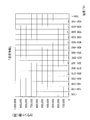
- a schematic view showing the entire configuration of a judgment system of an exhaust gas treatment apparatus Schematic diagram showing the configuration of each of the first and second working machines Histogram showing count number of temperature measurement value included in "temperature information” Histogram showing the count number of the temperature measurement value included in the "first heat damage information” and “second heat damage information” of the diesel particulate filter installed in the first work machine
- FIG. 1 is a schematic view showing an entire configuration of a judgment system 100 of an exhaust gas processing device according to the present embodiment.
- the determination system 100 includes a first work machine 1, a second work machine 2, a GPS satellite 3, a communication satellite 4, a data server 5, a network 6, and a terminal computer 7.
- FIG. 2 is a schematic view showing a part of the configuration of each of the first and second working machines 1 and 2.
- Each of the first and second working machines 1 and 2 is a vehicle for performing work such as digging, leveling, or transporting earth and sand at a construction site such as a mine or a road.
- Each of the first and second work machines 1 and 2 is, for example, a hydraulic shovel, a wheel loader, a bulldozer, a motor grader, a crane, and a forklift.
- each of the first and second working machines 1 and 2 includes an engine 10, a diesel particulate filter (hereinafter referred to as DPF) 20, a selective reduction catalyst (hereinafter referred to as SCR) 30, a controller 40, and An antenna 50 is provided.
- DPF diesel particulate filter
- SCR selective reduction catalyst
- the engine 10 is an internal combustion engine as a drive source.
- the engine 10 is a diesel engine.
- the DPF 20 is an example of the “exhaust gas processing device” according to the present embodiment.
- the DPF 20 is connected to the exhaust side of the engine 10.
- the DPF 20 collects PM contained in the exhaust gas.
- the DPF 20 needs to be removed from the work machine and periodically maintained in order to remove clogging with PM that can not be removed by forced regeneration described later.
- the DPF 20 which has received regular maintenance may be mounted on a work machine different from the work machine previously mounted.
- the DPF 20 includes a case 21, a DOC 22, a catalyzed soot filter: Catalyzed Soot Filter (hereinafter referred to as CSF) 23, a temperature sensor 24, and a differential pressure sensor 25.
- CSF Catalyzed Soot Filter
- Case 21 accommodates DOC 22 and CSF 23.
- a temperature sensor 24 and a differential pressure sensor 25 are attached to the case 21.
- the DOC 22 is a catalyst that oxidizes and heats the dosing fuel supplied into the exhaust gas as needed to raise the temperature of the exhaust gas to a predetermined high temperature range.
- the heated exhaust gas is used for forced regeneration of CSF 23 described later.
- the dosing fuel for example, the same light oil as the engine fuel can be used. Dosing fuel is supplied into the exhaust gas from a dosing fuel injection device (not shown) and flows into the DOC 22 together with the exhaust gas.
- a Pt / Pd alloy can be used as the DOC 22 oxidation catalyst.
- this oxidation catalyst is exposed to high temperature for a long time and suffers from heat damage, it gradually aggregates and the catalyst performance is degraded.
- the CSF23 is a filter which collects PM in exhaust gas.
- the CSF 23 has a honeycomb structure having a large number of small holes.
- the small holes of the CSF 23 include an inflow hole opened at the inlet side and sealed at the outlet side, and an outflow hole sealed at the inlet side and opened at the outlet side.
- the inflow holes and the outflow holes are alternately arranged via the boundary wall, and exhaust gas flowing in from the inflow holes passes through the boundary wall and passes out to the outflow hole. PM is trapped by the boundary wall.
- Ceramics such as cordierite and silicon carbide, or metals, such as stainless steel and aluminum, can be used, and it is suitably chosen according to a use.
- the inlet side of the CSF 23 is coated with an oxidation catalyst (for example, Pt) which is different in material from the DOC 22.
- This oxidation catalyst also gradually condenses and degrades catalyst performance when it is exposed to high temperature for a long time and suffers from heat damage.
- the temperature sensor 24 measures the exhaust gas temperature on the outlet side (downstream side) of the CSF 23. The temperature sensor 24 outputs the measured value to the controller 40.
- the differential pressure sensor 25 has a first pressure sensor 251 and a second pressure sensor 252.
- the first pressure sensor 251 measures the exhaust gas pressure on the inlet side (upstream side) of the CSF 23.
- the second pressure sensor 252 measures the exhaust gas pressure on the outlet side of the CSF 23.
- Each of the first pressure sensor 251 and the second pressure sensor 252 outputs a measured value to the controller 40.
- SCR 30 The SCR 30 is connected to the downstream side of the DPF 20.
- SCR30 is ammonia as a reducing agent, reduces and purifies NO X in the exhaust gas. Since urea may be crystallized and precipitated in the SCR 30, decomposition of the precipitate is performed using the heated exhaust gas as in the case of forced regeneration of the DPF 20.
- the controller 40 includes a unique identification code storage unit 41, a temperature acquisition unit 42, a transmission unit 43, and a forced regeneration execution unit 44.
- the unique identification code storage unit 41 stores a "DPF unique identification code” indicating the DPF 20 currently mounted on the host vehicle, and a "vehicle unique identification code” indicating the host vehicle.
- the “DPF unique identification code” is represented by, for example, a character string (number or / and character).
- the DPF unique identification code is an indicator for identifying each DPF 20. Therefore, the DPF unique identification code of the DPF 20 mounted on the first work machine 1 is different from the DPF unique identification code of the DPF 20 mounted on the second work machine 2.
- the “vehicle unique identification code” is represented by, for example, a character string.
- the vehicle unique identification code is a sign for identifying each work machine 1, 2. Therefore, the vehicle unique identification code of the first work machine 1 is different from the vehicle unique identification code of the second work machine 2.
- the temperature measurement value output from the temperature sensor 24 of the DPF 20 is input to the temperature acquisition unit 42.
- the temperature acquisition unit 42 acquires a temperature measurement value every predetermined time (for example, one minute). Then, the temperature acquisition unit 42 generates “temperature information” by aggregating the temperature measurement values acquired every predetermined time every predetermined period (for example, 24 hours).
- FIG. 3 is a histogram showing the count number of temperature measurement values included in the “temperature information”.
- the horizontal axis of the histogram represents the temperature range divided at every predetermined temperature (50 ° C. in FIG. 3), and the vertical axis of the histogram represents the count number of temperature measurement values belonging to each temperature range.
- the temperature acquisition unit 42 generates “specific temperature information” in which the “temperature information”, the “DPF specific identification code”, and the “vehicle specific identification code” are associated with each other.
- the transmission unit 43 transmits the “specific temperature information” generated by the temperature acquisition unit 42 from the antenna 50 to the data server 5 via the GPS satellite 3 or the communication satellite 4.
- the pressure measurement value output from each of the first and second pressure sensors 251 and 252 of the DPF 20 is input to the forced regeneration execution unit 44.
- the forced regeneration execution unit 44 calculates the difference between the pressure measurement values from the first and second pressure sensors 251 and 252, respectively. When the difference between the pressure measurement values becomes equal to or greater than a predetermined value, the forced regeneration execution unit 44 determines that clogging has occurred in the DPF 20 (specifically, the CSF 23), and executes forced regeneration of the DPF 20.
- the forced regeneration execution unit 44 supplies dosing fuel into the exhaust gas discharged from the engine 10 when it is determined that clogging has occurred.
- the reaction heat obtained by the oxidation heat of the dosing fuel in the DOC 22 is sent to the CSF 23, and the PM accumulated in the CSF 23 is burned and removed.
- CSF23 is forcedly regenerated.
- the data server 5 receives the “specific temperature information” transmitted from the first and second work machines 1 and 2 respectively.
- the “specific temperature information” is transmitted from the first and second work machines 1 and 2 at predetermined intervals.
- the data server 5 generates “heat damage information” indicating the degree of heat damage of each DPF 20 by aggregating “temperature information” associated with “DPF unique identification code” for each “vehicle unique identification code”. .
- the data server 5 is associated with the DPF 20 mounted on the first work machine 1 From the obtained "temperature information”, “first heat damage information” tabulated for the first work machine 1 and “second heat damage information” tabulated for the second work machine 2 are generated.
- the “first heat damage information” indicates the degree of heat damage received while the DPF 20 currently mounted on the first work machine 1 is mounted on the first work machine 1.
- the “second heat damage information” indicates the degree of heat damage that the DPF 20 currently mounted on the first work machine 1 has received while being mounted on the second work machine 1 previously.
- FIG. 4 is a histogram showing the counted number of temperature measurement values included in the “first heat damage information” and the “second heat damage information” of the DPF 20 currently mounted on the first work machine 1.
- the “DPF unique identification code” of the DPF 20 currently mounted on the first work machine 1 is “9999x”, and the “vehicle unique identification code” of the first work machine 1 is “111a”.
- the “vehicle unique identification code” of the working machine 2 is “222a”.
- Terminal computer 7 is a terminal for determining whether the DPF 20 mounted on each of the first and second work machines 1 and 2 can be used continuously.
- the terminal computer 7 is connected to the data server 5 via the network 6.
- the terminal computer 7 includes a thermal damage information acquisition unit 71 and a usability determination unit 72.
- the thermal damage information acquisition unit 71 is an example of an “acquisition unit”
- the availability determination unit 72 is an example of a “determination unit”.
- the thermal damage information acquisition unit 71 acquires “thermal damage information” indicating the degree of thermal damage of the DPF 20 that is the object of which the availability is to be determined, based on the “DPF unique identification code” of the DPF 20.
- the thermal damage information acquisition unit 71 acquires the “accumulated thermal damage information” by accumulating the acquired “thermal damage information” (acquisition process).
- the thermal damage information acquisition unit 71 determines that “the DPF unique identification code of the DPF 20” is associated First heat damage information and second heat damage information are acquired from the data server 5. Then, the thermal damage information acquisition unit 71 accumulates the count numbers of the temperature measurement values included in the “first thermal damage information” and the “second thermal damage information” for each temperature range to obtain “accumulated thermal damage information”. To get FIG. 6 is a histogram showing the counted number of temperature measurement values included in the “accumulated heat damage information” of the DPF 20 currently mounted on the first work machine 1.
- the availability determination unit 72 determines the availability of the DPF 20 based on the “cumulative thermal damage information” acquired by the thermal damage information acquisition unit 71 (determination step). For example, the availability determination unit 72 converts the count number of the temperature measurement value included in the "accumulated thermal damage information" into an index value, and determines that the index value is unusable if the index value is larger than the threshold, and the index value is equal to or less than the threshold If there is, it can be determined that it can be used. In this way, by using the "accumulated thermal damage information", it is possible to quantitatively grasp the degree of thermal damage accumulated in each DPF 20 mounted on each of the first and second work machines 1 and 2; The availability of the DPF 20 can be determined with high accuracy.
- the “cumulative heat damage information” of the DPF 20 currently mounted on the first work machine 1 indicates “the degree of heat damage received while being mounted on the first work machine 1”. Not only “1 heat damage information” but also “second heat damage information” indicating the degree of heat damage received while being mounted on the second working machine 1 is included. Therefore, even if the DPF 20 has been installed in another work machine, the degree of heat damage in the current DPF 20 can be grasped.
- the availability determination unit 72 determine the availability of the DPF 20 based on the count number of the temperature measurement value of a predetermined temperature or more among the temperature measurement values included in the “accumulated thermal damage information”.
- the predetermined temperature can be set to a temperature at which the catalyst used in each DPF 20 may aggregate (for example, about 650 ° C. if the catalyst is Pt). As described above, since the degree of aggregation of the catalyst in the DPF 20 can be grasped by using the count number of the temperature measurement value equal to or higher than the predetermined temperature, the availability of the DPF 20 can be determined more accurately.
- the DPF 20 includes the DOC 22 and the CSF 23, but is not limited thereto.
- the DPF 20 may have at least one of DOC 22 and CSF 23.
- the determination system 100 includes the first work machine 1 and the second work machine 2 in the above embodiment, the present invention is not limited to this.
- the determination system 100 may include three or more work machines.
- the "cumulative heat damage information” includes the temperature measurement value below the predetermined temperature at which the catalyst may be aggregated, but the present invention is not limited to this.
- the availability determination unit 72 determines the availability of the DPF 20 based only on the count number of the temperature measurement values above the predetermined temperature among the temperature measurement values included in the “accumulated thermal damage information”, “the cumulative thermal damage information” Does not have to include temperature measurement values below a predetermined temperature.
- the "cumulative heat damage information” includes the temperature measurement value measured by the temperature sensor 24, but the present invention is not limited to this.
- the “cumulative thermal damage information” may be any information that indicates thermal damage in the DPF 20.
- the number of times of forced regeneration in the DPF 20 can be used instead of the temperature measurement value. In this case, if the number of forced regenerations is greater than the number of thresholds, the availability determination unit 72 can determine that the number of forced regenerations is not available.
- the temperature sensor 24 measures the exhaust gas temperature on the outlet side of the CSF 23.
- the exhaust gas temperature on the inlet side of the CSF 23 may be measured, or the exhaust gas temperature on the inlet side of the DOC 22 May be
Landscapes
- Engineering & Computer Science (AREA)
- Chemical & Material Sciences (AREA)
- Chemical Kinetics & Catalysis (AREA)
- Combustion & Propulsion (AREA)
- Mechanical Engineering (AREA)
- General Engineering & Computer Science (AREA)
- Health & Medical Sciences (AREA)
- Toxicology (AREA)
- Materials Engineering (AREA)
- Exhaust Gas After Treatment (AREA)
- Processes For Solid Components From Exhaust (AREA)
Abstract
DPFの判定方法は、第1作業機械(1)に搭載され、DOC(22)及びCSF(23)を含むDPF(20)の熱被害度合いを示す熱被害情報を、DPF(20)の固有識別符号に基づいて取得し、熱被害情報を累積することによって累積熱被害情報を取得する取得工程と、累積熱被害情報に基づいてDPF(20)の使用可否を判定する判定工程とを備える。
Description
本発明は、排ガス処理装置の判定方法及び排ガス処理装置の判定システムに関する。
油圧ショベル、ホイールローダ、或いはダンプトラック等の作業機械では、ディーゼルエンジンからの排ガス中に含まれる粒子状物質:Particulate Matter(以降PMと記載)の処理のため、ディーゼル酸化触媒:Diesel Oxidation Catalyst(以降DOCと記載)を含む排ガス処理装置が設けられている。
PMには、煤(カーボンスート)とアッシュ(灰分)が含まれる。煤は、ディーゼル酸化触媒の触媒作用によって燃焼が促進されることで除去されるが、燃焼させるだけでは十分除去することはできない。また、アッシュは、エンジンオイルなどに含まれる金属系添加物の燃え残りであり、フィルタを高温にしても燃焼除去できない。
そのため、排ガス処理装置を作業機械から取り外して、PMによる目詰まりを定期的にメンテナンスする必要がある(特許文献1参照)。
ところで、排ガス処理装置が高温に長時間曝されて熱被害を受けると、触媒が凝集して処理性能が低下して使用できなくなってしまうため、処理性能が低下した排ガス処理装置を廃棄する必要がある。
しかしながら、排ガス処理装置の熱被害度合いを定量的に把握することは容易ではないため、排ガス処理装置の使用可否を精度良く判定することは困難である。
特に、定期メンテナンスを受けた排ガス処理装置は、以前に搭載されていた作業機械とは別の作業機械に搭載される場合が多いため、当該排ガス処理装置における累積的な熱被害度合いを考慮して精度良く使用可否を判定することは困難である。
本発明は、精度良く排ガス処理装置の使用可否を判定可能な技術を提供することを目的とする。
本発明に係る排ガス処理装置の判定方法は、作業機械に搭載され、ディーゼル酸化触媒及び触媒化スートフィルタの少なくとも一方を有する排ガス処理装置の熱被害度合いを示す熱被害情報を、排ガス処理装置の固有識別符号に基づいて累積することによって累積熱被害情報を取得する取得工程と、累積熱被害情報に基づいて、排ガス処理装置の使用可否を判定する判定工程とを備える。
本発明によれば、精度良く排ガス処理装置の使用可否を判定可能な排ガス処理装置の判定方法及び排ガス処理装置の判定システムを提供することができる。
(排ガス処理装置の判定システムの全体構成)
図1は、本実施形態に係る排ガス処理装置の判定システム100の全体構成を示す模式図である。
図1は、本実施形態に係る排ガス処理装置の判定システム100の全体構成を示す模式図である。
判定システム100は、第1作業機械1、第2作業機械2、GPS衛星3、通信衛星4、データサーバ5、ネットワーク6、及び端末コンピュータ7を備える。
[第1及び第2作業機械1,2]
図2は、第1及び第2作業機械1,2それぞれの構成の一部を示す模式図である。
図2は、第1及び第2作業機械1,2それぞれの構成の一部を示す模式図である。
第1及び第2作業機械1,2のそれぞれは、鉱山や道路等の建設現場において、掘削、地均し、或いは、土砂運搬などの作業を行うための車両である。第1及び第2作業機械1,2のそれぞれは、例えば、油圧ショベル、ホイールローダ、ブルドーザ、モータグレーダ、クレーン、及びフォークリフトなどである。
図2に示すように、第1及び第2作業機械1,2それぞれは、エンジン10、ディーゼルパーティキュレートフィルタ(以降DPFと記載)20、選択還元触媒(以降SCRと記載)30、コントローラ40、及びアンテナ50を備える。
(1)エンジン10
エンジン10は、駆動源としての内燃機関である。本実施形態において、エンジン10は、ディーゼルエンジンである。エンジン10から排出される排ガスには、PM及びNOXなどが含まれている。
エンジン10は、駆動源としての内燃機関である。本実施形態において、エンジン10は、ディーゼルエンジンである。エンジン10から排出される排ガスには、PM及びNOXなどが含まれている。
(2)DPF20
DPF20は、本実施形態に係る「排ガス処理装置」の一例である。DPF20は、エンジン10の排気側に接続される。DPF20は、排ガス中に含まれるPMを捕集する。DPF20は、後述する強制再生では除去しきれないPMによる目詰まりを取り除くため、作業機械から取り外して、定期的にメンテナンスする必要がある。
DPF20は、本実施形態に係る「排ガス処理装置」の一例である。DPF20は、エンジン10の排気側に接続される。DPF20は、排ガス中に含まれるPMを捕集する。DPF20は、後述する強制再生では除去しきれないPMによる目詰まりを取り除くため、作業機械から取り外して、定期的にメンテナンスする必要がある。
ここで、定期的なメンテナンスを受けたDPF20は、以前に搭載されていた作業機械とは別の作業機械に搭載される場合がある。本実施形態では、以前、第2作業機械2に搭載されていたDPF20が、現在は、第1作業機械1に搭載されている場合が想定されている。
DPF20は、ケース21、DOC22、触媒化スートフィルタ:Catalyzed Soot Filter(以降CSFと記載)23、温度センサ24、差圧センサ25を備える。
ケース21は、DOC22とCSF23とを収容する。ケース21には、温度センサ24と差圧センサ25とが取り付けられる。
DOC22は、排ガス中に必要に応じて供給されるドージング燃料を酸化発熱させて、排ガス温度を所定の高温域まで昇温させる触媒である。昇温した排ガスは、後述するCSF23の強制再生に利用される。ドージング燃料には、例えばエンジン燃料と同じ軽油を用いることができる。ドージング燃料は、図示しないドージング用の燃料噴射装置から排ガス中に供給され、排ガスとともにDOC22に流入する。
DOC22の酸化触媒には、例えばPt/Pd合金を用いることができる。この酸化触媒は、高温に長時間曝されて熱被害を受けると、徐々に凝集して触媒性能が低下する。
CSF23は、排ガス中のPMを捕集するフィルタである。CSF23は、多数の小孔を有するハニカム構造を有する。CSF23の小孔は、入口側で開口して出口側で目封じされた流入孔と、入口側で目封じされて出口側で開口した流出孔とを含む。流入孔と流出孔は、境界壁を介して交互に配置されており、流入孔から流入した排気ガスが、境界壁を通過して流出孔に抜けるようになっている。PMは、境界壁によって捕集される。
CSF23にPMが堆積すると、DOC22によって昇温された排ガスを利用してPMを燃焼除去する、いわゆる強制再生が実行される。CSF23にPMが堆積したか否かは、差圧センサ25の測定値に基づいてコントローラ40が判断する。
CSF23の材質には、コージェライトや炭化珪素等のセラミックス、または、ステンレスやアルミニウム等の金属を用いることができ、用途に応じて適宜選択される。
CSF23の入口側には、DOC22とは材質の異なる酸化触媒(例えば、Pt)がコーティングされている。この酸化触媒も、高温に長時間曝されて熱被害を受けると、徐々に凝集して触媒性能が低下する。
温度センサ24は、CSF23の出口側(下流側)の排ガス温度を測定する。温度センサ24は、測定値をコントローラ40に出力する。
差圧センサ25は、第1圧力センサ251及び第2圧力センサ252を有する。第1圧力センサ251は、CSF23の入口側(上流側)の排ガス圧力を測定する。第2圧力センサ252は、CSF23の出口側の排ガス圧力を測定する。第1圧力センサ251及び第2圧力センサ252それぞれは、測定値をコントローラ40に出力する。
(3)SCR30
SCR30は、DPF20の下流側に接続される。SCR30は、アンモニアを還元剤として、排ガス中のNOXを還元浄化する。SCR30には尿素が結晶化して析出する場合があるため、DPF20の強制再生と同様、昇温された排ガスを利用して析出物の分解が行われる。
SCR30は、DPF20の下流側に接続される。SCR30は、アンモニアを還元剤として、排ガス中のNOXを還元浄化する。SCR30には尿素が結晶化して析出する場合があるため、DPF20の強制再生と同様、昇温された排ガスを利用して析出物の分解が行われる。
(4)コントローラ40
コントローラ40は、固有識別符号記憶部41、温度取得部42、送信部43、及び強制再生実行部44を有する。
コントローラ40は、固有識別符号記憶部41、温度取得部42、送信部43、及び強制再生実行部44を有する。
固有識別符号記憶部41は、現在、自車両に搭載されているDPF20を示す「DPF固有識別符号」と、自車両を示す「車両固有識別符号」とを記憶している。
「DPF固有識別符号」は、例えば文字列(数字又は/及び文字)によって表される。DPF固有識別符号は、各DPF20を識別するための標識である。従って、第1作業機械1に搭載されているDPF20のDPF固有識別符号は、第2作業機械2に搭載されているDPF20のDPF固有識別符号とは異なる。
「車両固有識別符号」は、例えば文字列によって表される。車両固有識別符号は、各作業機械1,2を識別するための標識である。従って、第1作業機械1の車両固有識別符号は、第2作業機械2の車両固有識別符号とは異なる。
温度取得部42には、DPF20の温度センサ24から出力される温度測定値が入力される。本実施形態において、温度取得部42は、所定時間(例えば、1分)ごとに温度測定値を取得する。そして、温度取得部42は、所定時間ごとに取得された温度測定値を所定期間(例えば、24時間)ごとに集計することによって、「温度情報」を生成する。
図3は、「温度情報」に含まれる温度測定値のカウント数を示すヒストグラムである。ヒストグラムの横軸は、所定温度(図3では、50℃)ごとに区切られた温度範囲を表し、ヒストグラムの縦軸は、各温度範囲に属する温度測定値のカウント数を表している。
温度取得部42は、「温度情報」と「DPF固有識別符号」と「車両固有識別符号」とを関連づけた「固有温度情報」を生成する。
送信部43は、温度取得部42によって生成された「固有温度情報」を、アンテナ50からGPS衛星3又は通信衛星4を介してデータサーバ5に送信する。
強制再生実行部44には、DPF20の第1及び第2圧力センサ251,252それぞれから出力される圧力測定値が入力される。強制再生実行部44は、第1及び第2圧力センサ251,252それぞれからの圧力測定値の差分を算出する。強制再生実行部44は、圧力測定値の差分が所定値以上になった場合、DPF20(具体的には、CSF23)において目詰まりが生じていると判断して、DPF20の強制再生を実行する。
具体的に、強制再生実行部44は、目詰まりが生じていると判断した場合、エンジン10から排出される排ガス中にドージング燃料を供給する。これにより、ドージング燃料がDOC22において酸化発熱して得られる反応熱がCSF23に送り込まれ、CSF23に堆積したPMが燃焼除去される。これによって、CSF23が強制再生される。
[データサーバ5]
データサーバ5は、第1及び第2作業機械1,2それぞれから送信される「固有温度情報」を受信する。「固有温度情報」は、第1及び第2作業機械1,2それぞれから、所定期間ごとに送信されてくる。
データサーバ5は、第1及び第2作業機械1,2それぞれから送信される「固有温度情報」を受信する。「固有温度情報」は、第1及び第2作業機械1,2それぞれから、所定期間ごとに送信されてくる。
上述のとおり、「固有温度情報」では、所定期間ごとに集計された温度測定値を示す「温度情報」と、「DPF固有識別符号」と、「車両固有識別符号」とが関連づけられている。
データサーバ5は、「DPF固有識別符号」に関連づけられた「温度情報」を、「車両固有識別符号」ごとに集計することによって、各DPF20の熱被害度合いを示す「熱被害情報」を生成する。
具体的には、現在、第1作業機械1に搭載されているDPF20は、以前、第2作業機械2に搭載されていたため、データサーバ5は、第1作業機械1に搭載されたDPF20に関連づけられた「温度情報」から、第1作業機械1について集計した「第1熱被害情報」と、第2作業機械2について集計した「第2熱被害情報」とを生成する。
「第1熱被害情報」は、第1作業機械1に現在搭載されているDPF20が、第1作業機械1に搭載されている間に受けた熱被害度合いを示す。「第2熱被害情報」は、第1作業機械1に現在搭載されているDPF20が、第2作業機械1に以前搭載されている間に受けた熱被害度合いを示す。
図4は、第1作業機械1に現在搭載されているDPF20の「第1熱被害情報」と「第2熱被害情報」とに含まれる温度測定値のカウント数を示すヒストグラムである。
図4において、第1作業機械1に現在搭載されているDPF20の「DPF固有識別符号」は「9999x」であり、第1作業機械1の「車両固有識別符号」は「111a」であり、第2作業機械2の「車両固有識別符号」は「222a」である。
[端末コンピュータ7]
端末コンピュータ7は、第1及び第2作業機械1,2それぞれに搭載されているDPF20を継続して使用できるか否かを判断するための端末である。端末コンピュータ7は、ネットワーク6を介してデータサーバ5に接続される。
端末コンピュータ7は、第1及び第2作業機械1,2それぞれに搭載されているDPF20を継続して使用できるか否かを判断するための端末である。端末コンピュータ7は、ネットワーク6を介してデータサーバ5に接続される。
図5に示すように、端末コンピュータ7は、熱被害情報取得部71及び使用可否判定部72を有する。本実施形態において、熱被害情報取得部71は「取得手段」の一例であり、使用可否判定部72は「判定手段」の一例である。
熱被害情報取得部71は、使用可否を判定する対象であるDPF20の熱被害度合いを示す「熱被害情報」を、当該DPF20の「DPF固有識別符号」に基づいて取得する。熱被害情報取得部71は、取得した「熱被害情報」を累積することによって「累積熱被害情報」を取得する(取得工程)。
例えば、第1作業機械1に現在搭載されているDPF20を継続して使用できるか否かを判断したい場合、熱被害情報取得部71は、当該DPF20の「DPF固有識別符号」に関連づけられた「第1熱被害情報」と「第2熱被害情報」とをデータサーバ5から取得する。そして、熱被害情報取得部71は、「第1熱被害情報」と「第2熱被害情報」とに含まれる温度測定値のカウント数を温度範囲ごとに累計することによって、「累積熱被害情報」を取得する。図6は、第1作業機械1に現在搭載されているDPF20の「累積熱被害情報」に含まれる温度測定値のカウント数を示すヒストグラムである。
使用可否判定部72は、熱被害情報取得部71によって取得された「累積熱被害情報」に基づいて、DPF20の使用可否を判定する(判定工程)。例えば、使用可否判定部72は、「累積熱被害情報」に含まれる温度測定値のカウント数を指標値化し、その指標値が閾値よりも大きければ使用不可と判定し、指標値が閾値以下であれば使用可と判定することができる。このように、「累積熱被害情報」を用いることによって、第1及び第2作業機械1,2それぞれに搭載された各DPF20に蓄積した熱被害度合いを定量的に把握することができるため、各DPF20の使用可否を精度良く判定することができる。
特に、本実施形態では、第1作業機械1に現在搭載されているDPF20の「累積熱被害情報」には、第1作業機械1に搭載されている間に受けた熱被害度合いを示す「第1熱被害情報」だけでなく、第2作業機械1に搭載されている間に受けた熱被害度合いを示す「第2熱被害情報」も含まれている。従って、DPF20が別の作業機械に搭載されていた経歴があったとしても、現状のDPF20における熱被害度合いを把握することができる。
また、使用可否判定部72は、「累積熱被害情報」に含まれる温度測定値のうち所定温度以上の温度測定値のカウント数に基づいて、DPF20の使用可否を判定することが好ましい。所定温度は、各DPF20に用いられている触媒が凝集するおそれのある温度(例えば、触媒がPtであれば、約650℃)に設定することができる。このように、所定温度以上の温度測定値のカウント数を用いることによって、DPF20における触媒の凝集度合いを把握できるため、DPF20の使用可否を更に精度良く判定することができる。
(他の実施形態)
上記実施形態において、DPF20は、DOC22及びCSF23を含むこととしたが、これに限られるものではない。DPF20は、DOC22及びCSF23の少なくとも一方を有していればよい。
上記実施形態において、DPF20は、DOC22及びCSF23を含むこととしたが、これに限られるものではない。DPF20は、DOC22及びCSF23の少なくとも一方を有していればよい。
上記実施形態において、判定システム100は、第1作業機械1及び第2作業機械2を備えることとしたが、これに限られるものではない。判定システム100は、3台以上の作業機械を備えていてもよい。
上記実施形態において、「累積熱被害情報」には、触媒が凝集するおそれのある所定温度未満の温度測定値も含まれることとしたが、これに限られるものではない。使用可否判定部72が、「累積熱被害情報」に含まれる温度測定値のうち所定温度以上の温度測定値のカウント数のみに基づいてDPF20の使用可否を判定する場合、「累積熱被害情報」には所定温度未満の温度測定値は含まれていなくてもよい。
上記実施形態において、「累積熱被害情報」には、温度センサ24によって測定された温度測定値が含まれることとしたが、これに限られるものではない。「累積熱被害情報」は、DPF20における熱被害を示すものであればよく、例えば、温度測定値に代えて、DPF20における強制再生の回数を用いることができる。この場合、使用可否判定部72は、強制再生の回数が閾値の回数よりも多ければ使用不可と判定し、強制再生の回数が閾値の回数以下であれば使用可と判定することができる。
上記実施形態において、温度センサ24は、CSF23の出口側の排ガス温度を測定することとしたが、CSF23の入口側の排ガス温度を測定してもよいし、DOC22の入口側の排ガス温度を測定してもよい。
1 第1作業機械
2 第2作業機械
3 GPS衛星
4 通信衛星
5 データサーバ
6 ネットワーク
7 端末コンピュータ
10 エンジン
20 DPF
21 ケース
22 DOC
23 CSF
24 温度センサ
25 差圧センサ
30 SCR
40 コントローラ
50 アンテナ
71 熱被害情報取得部
72 使用可否判定部
100 判定システム
2 第2作業機械
3 GPS衛星
4 通信衛星
5 データサーバ
6 ネットワーク
7 端末コンピュータ
10 エンジン
20 DPF
21 ケース
22 DOC
23 CSF
24 温度センサ
25 差圧センサ
30 SCR
40 コントローラ
50 アンテナ
71 熱被害情報取得部
72 使用可否判定部
100 判定システム
Claims (4)
- 作業機械に搭載され、ディーゼル酸化触媒及び触媒化スートフィルタの少なくとも一方を有する排ガス処理装置の熱被害度合いを示す熱被害情報を、前記排ガス処理装置の固有識別符号に基づいて取得し、前記熱被害情報を累積することによって累積熱被害情報を取得する取得工程と、
前記累積熱被害情報に基づいて、前記排ガス処理装置の使用可否を判定する判定工程と、
を備える排ガス処理装置の判定方法。 - 前記取得工程は、前記排ガス処理装置が第1作業機械に搭載されている間に受けた熱被害度合いを示す第1熱被害情報と、前記排ガス処理装置が第2作業機械に搭載されている間に受けた熱被害度合いを示す第2熱被害情報とを取得し、前記第1熱被害情報と前記第2熱被害情報を累積することによって前記累積熱被害情報を取得する取得工程である、
請求項1に記載の排ガス処理装置の判定方法。 - 作業機械に搭載され、ディーゼル酸化触媒または触媒化スートフィルタを有する排ガス処理装置の熱被害度合いを示す熱被害情報を、前記排ガス処理装置の固有識別符号に基づいて取得し、前記熱被害情報を累積することによって累積熱被害情報を取得する取得手段と、
前記累積熱被害情報に基づいて、前記排ガス処理装置の使用可否を判定する判定手段と、
を備える排ガス処理装置の判定システム。 - 少なくとも、第1作業機械に搭載されている間に受けた熱被害度合いを示す第1熱被害情報と、第2作業機械に搭載されている間に受けた熱被害度合いを示す第2熱被害情報とを記憶する記憶手段を更に備え、
前記取得手段は、前記第1熱被害情報と前記第2熱被害情報とを前記固有識別符号に基づいて取得し、前記第1熱被害情報と前記第2熱被害情報とを累積することによって前記累積熱被害情報を取得する、
請求項3に記載の排ガス処理装置の判定システム。
Priority Applications (4)
| Application Number | Priority Date | Filing Date | Title |
|---|---|---|---|
| KR1020197028215A KR20190116517A (ko) | 2017-08-31 | 2018-08-28 | 배기 가스 처리 장치의 판정 방법 및 배기 가스 처리 장치의 판정 시스템 |
| CN201880024918.6A CN110546354B (zh) | 2017-08-31 | 2018-08-28 | 排气处理装置的判定方法以及排气处理装置的判定系统 |
| US16/609,343 US10920648B2 (en) | 2017-08-31 | 2018-08-28 | Determination method for exhaust gas treatment device and determination system for exhaust gas treatment device |
| DE112018001443.6T DE112018001443T5 (de) | 2017-08-31 | 2018-08-28 | Bestimmungsverfahren für eine abgasbehandlungsvorrichtung und bestimmungssystem für eine abgasbehandlungsvorrichtung |
Applications Claiming Priority (2)
| Application Number | Priority Date | Filing Date | Title |
|---|---|---|---|
| JP2017-166540 | 2017-08-31 | ||
| JP2017166540A JP6865138B2 (ja) | 2017-08-31 | 2017-08-31 | 排ガス処理装置の判定方法及び排ガス処理装置の判定システム |
Publications (1)
| Publication Number | Publication Date |
|---|---|
| WO2019044849A1 true WO2019044849A1 (ja) | 2019-03-07 |
Family
ID=65525611
Family Applications (1)
| Application Number | Title | Priority Date | Filing Date |
|---|---|---|---|
| PCT/JP2018/031811 Ceased WO2019044849A1 (ja) | 2017-08-31 | 2018-08-28 | 排ガス処理装置の判定方法及び排ガス処理装置の判定システム |
Country Status (6)
| Country | Link |
|---|---|
| US (1) | US10920648B2 (ja) |
| JP (1) | JP6865138B2 (ja) |
| KR (1) | KR20190116517A (ja) |
| CN (1) | CN110546354B (ja) |
| DE (1) | DE112018001443T5 (ja) |
| WO (1) | WO2019044849A1 (ja) |
Families Citing this family (4)
| Publication number | Priority date | Publication date | Assignee | Title |
|---|---|---|---|---|
| JP7342745B2 (ja) * | 2020-03-11 | 2023-09-12 | トヨタ自動車株式会社 | 車両用触媒の再利用方法 |
| JP7211388B2 (ja) * | 2020-03-25 | 2023-01-24 | トヨタ自動車株式会社 | 触媒の再利用評価システム |
| CN113177314B (zh) * | 2021-04-28 | 2024-06-04 | 一汽解放汽车有限公司 | 一种dpf主动再生方法、装置、计算机设备和存储介质 |
| JP2023175088A (ja) * | 2022-05-30 | 2023-12-12 | 株式会社Subaru | 車両の排気系触媒の管理装置 |
Citations (3)
| Publication number | Priority date | Publication date | Assignee | Title |
|---|---|---|---|---|
| JP2002195056A (ja) * | 2000-12-22 | 2002-07-10 | Central Res Inst Of Electric Power Ind | ガスタービン高温部品の廃却損最小化方法及びシステム及びガスタービン保守最適化支援プログラムを記録したコンピュータ読取可能な記録媒体 |
| JP2015071991A (ja) * | 2013-10-04 | 2015-04-16 | いすゞ自動車株式会社 | 診断装置 |
| JP2015223583A (ja) * | 2014-05-30 | 2015-12-14 | 日立建機株式会社 | 熱機関における排ガス酸化触媒の劣化検知・回復方法、該方法を実施する熱機関の排ガス浄化装置および該排ガス浄化装置を備えた機械装置 |
Family Cites Families (5)
| Publication number | Priority date | Publication date | Assignee | Title |
|---|---|---|---|---|
| DE10017940C2 (de) | 2000-04-11 | 2003-01-23 | Omg Ag & Co Kg | Verfahren zur Überprüfung der Funktionstüchtigkeit eines Stickoxid-Speicherkatalysators |
| JP2002122049A (ja) * | 2000-08-10 | 2002-04-26 | Akinari Ito | 内燃機関による空気汚染防止システム、空気汚染防止システムを含む内燃機関、燃料処理方法及び燃料処理装置 |
| EP1898361B1 (en) * | 2006-09-06 | 2010-08-25 | Saab Ab | Arrangement, method and computer program product for enhanced prognostics |
| US8336292B2 (en) * | 2008-11-12 | 2012-12-25 | Caterpillar Inc. | Exhaust component having permanently associated life indicator |
| JP5350916B2 (ja) | 2009-07-03 | 2013-11-27 | 日立建機株式会社 | 排気浄化装置の管理システム、排気浄化装置の管理方法 |
-
2017
- 2017-08-31 JP JP2017166540A patent/JP6865138B2/ja active Active
-
2018
- 2018-08-28 KR KR1020197028215A patent/KR20190116517A/ko not_active Withdrawn
- 2018-08-28 US US16/609,343 patent/US10920648B2/en active Active
- 2018-08-28 DE DE112018001443.6T patent/DE112018001443T5/de not_active Withdrawn
- 2018-08-28 WO PCT/JP2018/031811 patent/WO2019044849A1/ja not_active Ceased
- 2018-08-28 CN CN201880024918.6A patent/CN110546354B/zh active Active
Patent Citations (3)
| Publication number | Priority date | Publication date | Assignee | Title |
|---|---|---|---|---|
| JP2002195056A (ja) * | 2000-12-22 | 2002-07-10 | Central Res Inst Of Electric Power Ind | ガスタービン高温部品の廃却損最小化方法及びシステム及びガスタービン保守最適化支援プログラムを記録したコンピュータ読取可能な記録媒体 |
| JP2015071991A (ja) * | 2013-10-04 | 2015-04-16 | いすゞ自動車株式会社 | 診断装置 |
| JP2015223583A (ja) * | 2014-05-30 | 2015-12-14 | 日立建機株式会社 | 熱機関における排ガス酸化触媒の劣化検知・回復方法、該方法を実施する熱機関の排ガス浄化装置および該排ガス浄化装置を備えた機械装置 |
Also Published As
| Publication number | Publication date |
|---|---|
| JP2019044645A (ja) | 2019-03-22 |
| US10920648B2 (en) | 2021-02-16 |
| CN110546354A (zh) | 2019-12-06 |
| CN110546354B (zh) | 2022-03-18 |
| JP6865138B2 (ja) | 2021-04-28 |
| US20200049045A1 (en) | 2020-02-13 |
| DE112018001443T5 (de) | 2019-12-12 |
| KR20190116517A (ko) | 2019-10-14 |
Similar Documents
| Publication | Publication Date | Title |
|---|---|---|
| CN102782267B (zh) | Dpf的再生控制装置、再生控制方法及再生支持系统 | |
| EP3943722B1 (en) | Methods for operation of an emissions aftertreatment system for nox control during regeneration of diesel particulate filter | |
| JP6865138B2 (ja) | 排ガス処理装置の判定方法及び排ガス処理装置の判定システム | |
| JP5838265B1 (ja) | 後処理装置の管理装置、作業車両、管理システムおよび後処理装置の管理方法 | |
| KR101907727B1 (ko) | 건설 기계 | |
| CN109404107A (zh) | 柴油机颗粒捕集器碳载量估算方法 | |
| US9605626B2 (en) | Siloxane filtration system and method | |
| CN102373999A (zh) | 预计车辆微粒过滤器内峰值温度的方法和装置 | |
| EP2612003B1 (en) | Method and system for exhaust cleaning | |
| CN111336023B (zh) | 基于来自传感器的测量值和测量值的模型估计的燃料含量检测 | |
| CN102345492A (zh) | 用于监测车辆颗粒过滤器的再生频率的装置和方法 | |
| US12188390B2 (en) | Diagnosis device and diagnosis method | |
| CN111749769B (zh) | 一种dpf主动再生效率检测方法 | |
| US20060191258A1 (en) | Particulate trap regeneration control system | |
| JP6435641B2 (ja) | 管理システム | |
| CN114991919B (zh) | 一种颗粒捕集载体的再生时间设置方法及装置 | |
| JP2023109245A (ja) | 運転指示システムおよび運転指示方法 | |
| JP2023106800A (ja) | 処理装置、処理方法および排気ガス処理システム | |
| JP2003155912A (ja) | パティキュレートフィルタの溶損判定方法及び装置 | |
| JP2023106799A (ja) | 処理装置、処理方法および排気ガス処理システム | |
| JP2016003615A (ja) | 酸化触媒の熱劣化の検出方法及び装置 |
Legal Events
| Date | Code | Title | Description |
|---|---|---|---|
| 121 | Ep: the epo has been informed by wipo that ep was designated in this application |
Ref document number: 18851237 Country of ref document: EP Kind code of ref document: A1 |
|
| ENP | Entry into the national phase |
Ref document number: 20197028215 Country of ref document: KR Kind code of ref document: A |
|
| 122 | Ep: pct application non-entry in european phase |
Ref document number: 18851237 Country of ref document: EP Kind code of ref document: A1 |