WO2019044822A1 - 作業車両の制御システム、方法、及び作業車両 - Google Patents
作業車両の制御システム、方法、及び作業車両 Download PDFInfo
- Publication number
- WO2019044822A1 WO2019044822A1 PCT/JP2018/031752 JP2018031752W WO2019044822A1 WO 2019044822 A1 WO2019044822 A1 WO 2019044822A1 JP 2018031752 W JP2018031752 W JP 2018031752W WO 2019044822 A1 WO2019044822 A1 WO 2019044822A1
- Authority
- WO
- WIPO (PCT)
- Prior art keywords
- work vehicle
- target
- controller
- excavation
- distance
- Prior art date
- Legal status (The legal status is an assumption and is not a legal conclusion. Google has not performed a legal analysis and makes no representation as to the accuracy of the status listed.)
- Ceased
Links
Images






Classifications
-
- E—FIXED CONSTRUCTIONS
- E02—HYDRAULIC ENGINEERING; FOUNDATIONS; SOIL SHIFTING
- E02F—DREDGING; SOIL-SHIFTING
- E02F9/00—Component parts of dredgers or soil-shifting machines, not restricted to one of the kinds covered by groups E02F3/00 - E02F7/00
- E02F9/20—Drives; Control devices
- E02F9/22—Hydraulic or pneumatic drives
- E02F9/2221—Control of flow rate; Load sensing arrangements
- E02F9/2225—Control of flow rate; Load sensing arrangements using pressure-compensating valves
- E02F9/2228—Control of flow rate; Load sensing arrangements using pressure-compensating valves including an electronic controller
-
- E—FIXED CONSTRUCTIONS
- E02—HYDRAULIC ENGINEERING; FOUNDATIONS; SOIL SHIFTING
- E02F—DREDGING; SOIL-SHIFTING
- E02F3/00—Dredgers; Soil-shifting machines
- E02F3/04—Dredgers; Soil-shifting machines mechanically-driven
- E02F3/76—Graders, bulldozers, or the like with scraper plates or ploughshare-like elements; Levelling scarifying devices
- E02F3/7609—Scraper blade mounted forwardly of the tractor on a pair of pivoting arms which are linked to the sides of the tractor, e.g. bulldozers
- E02F3/7618—Scraper blade mounted forwardly of the tractor on a pair of pivoting arms which are linked to the sides of the tractor, e.g. bulldozers with the scraper blade adjustable relative to the pivoting arms about a horizontal axis
-
- E—FIXED CONSTRUCTIONS
- E02—HYDRAULIC ENGINEERING; FOUNDATIONS; SOIL SHIFTING
- E02F—DREDGING; SOIL-SHIFTING
- E02F3/00—Dredgers; Soil-shifting machines
- E02F3/04—Dredgers; Soil-shifting machines mechanically-driven
- E02F3/76—Graders, bulldozers, or the like with scraper plates or ploughshare-like elements; Levelling scarifying devices
- E02F3/80—Component parts
- E02F3/84—Drives or control devices therefor, e.g. hydraulic drive systems
- E02F3/841—Devices for controlling and guiding the whole machine, e.g. by feeler elements and reference lines placed exteriorly of the machine
-
- E—FIXED CONSTRUCTIONS
- E02—HYDRAULIC ENGINEERING; FOUNDATIONS; SOIL SHIFTING
- E02F—DREDGING; SOIL-SHIFTING
- E02F3/00—Dredgers; Soil-shifting machines
- E02F3/04—Dredgers; Soil-shifting machines mechanically-driven
- E02F3/76—Graders, bulldozers, or the like with scraper plates or ploughshare-like elements; Levelling scarifying devices
- E02F3/80—Component parts
- E02F3/84—Drives or control devices therefor, e.g. hydraulic drive systems
- E02F3/844—Drives or control devices therefor, e.g. hydraulic drive systems for positioning the blade, e.g. hydraulically
-
- E—FIXED CONSTRUCTIONS
- E02—HYDRAULIC ENGINEERING; FOUNDATIONS; SOIL SHIFTING
- E02F—DREDGING; SOIL-SHIFTING
- E02F9/00—Component parts of dredgers or soil-shifting machines, not restricted to one of the kinds covered by groups E02F3/00 - E02F7/00
- E02F9/20—Drives; Control devices
-
- E—FIXED CONSTRUCTIONS
- E02—HYDRAULIC ENGINEERING; FOUNDATIONS; SOIL SHIFTING
- E02F—DREDGING; SOIL-SHIFTING
- E02F9/00—Component parts of dredgers or soil-shifting machines, not restricted to one of the kinds covered by groups E02F3/00 - E02F7/00
- E02F9/20—Drives; Control devices
- E02F9/2025—Particular purposes of control systems not otherwise provided for
- E02F9/205—Remotely operated machines, e.g. unmanned vehicles
-
- E—FIXED CONSTRUCTIONS
- E02—HYDRAULIC ENGINEERING; FOUNDATIONS; SOIL SHIFTING
- E02F—DREDGING; SOIL-SHIFTING
- E02F9/00—Component parts of dredgers or soil-shifting machines, not restricted to one of the kinds covered by groups E02F3/00 - E02F7/00
- E02F9/26—Indicating devices
- E02F9/261—Surveying the work-site to be treated
- E02F9/262—Surveying the work-site to be treated with follow-up actions to control the work tool, e.g. controller
-
- E—FIXED CONSTRUCTIONS
- E02—HYDRAULIC ENGINEERING; FOUNDATIONS; SOIL SHIFTING
- E02F—DREDGING; SOIL-SHIFTING
- E02F9/00—Component parts of dredgers or soil-shifting machines, not restricted to one of the kinds covered by groups E02F3/00 - E02F7/00
- E02F9/26—Indicating devices
- E02F9/264—Sensors and their calibration for indicating the position of the work tool
- E02F9/265—Sensors and their calibration for indicating the position of the work tool with follow-up actions (e.g. control signals sent to actuate the work tool)
-
- G—PHYSICS
- G05—CONTROLLING; REGULATING
- G05D—SYSTEMS FOR CONTROLLING OR REGULATING NON-ELECTRIC VARIABLES
- G05D1/00—Control of position, course, altitude or attitude of land, water, air or space vehicles, e.g. using automatic pilots
- G05D1/02—Control of position or course in two dimensions
- G05D1/021—Control of position or course in two dimensions specially adapted to land vehicles
- G05D1/0268—Control of position or course in two dimensions specially adapted to land vehicles using internal positioning means
-
- G—PHYSICS
- G05—CONTROLLING; REGULATING
- G05D—SYSTEMS FOR CONTROLLING OR REGULATING NON-ELECTRIC VARIABLES
- G05D1/00—Control of position, course, altitude or attitude of land, water, air or space vehicles, e.g. using automatic pilots
- G05D1/02—Control of position or course in two dimensions
- G05D1/021—Control of position or course in two dimensions specially adapted to land vehicles
- G05D1/0268—Control of position or course in two dimensions specially adapted to land vehicles using internal positioning means
- G05D1/027—Control of position or course in two dimensions specially adapted to land vehicles using internal positioning means comprising intertial navigation means, e.g. azimuth detector
-
- G—PHYSICS
- G05—CONTROLLING; REGULATING
- G05D—SYSTEMS FOR CONTROLLING OR REGULATING NON-ELECTRIC VARIABLES
- G05D1/00—Control of position, course, altitude or attitude of land, water, air or space vehicles, e.g. using automatic pilots
- G05D1/02—Control of position or course in two dimensions
- G05D1/021—Control of position or course in two dimensions specially adapted to land vehicles
- G05D1/0268—Control of position or course in two dimensions specially adapted to land vehicles using internal positioning means
- G05D1/0274—Control of position or course in two dimensions specially adapted to land vehicles using internal positioning means using mapping information stored in a memory device
-
- G—PHYSICS
- G05—CONTROLLING; REGULATING
- G05D—SYSTEMS FOR CONTROLLING OR REGULATING NON-ELECTRIC VARIABLES
- G05D1/00—Control of position, course, altitude or attitude of land, water, air or space vehicles, e.g. using automatic pilots
- G05D1/02—Control of position or course in two dimensions
- G05D1/021—Control of position or course in two dimensions specially adapted to land vehicles
- G05D1/0276—Control of position or course in two dimensions specially adapted to land vehicles using signals provided by a source external to the vehicle
- G05D1/0278—Control of position or course in two dimensions specially adapted to land vehicles using signals provided by a source external to the vehicle using satellite positioning signals, e.g. GPS
Definitions
- the present invention relates to a control system, method, and work vehicle of a work vehicle.
- the work vehicle may perform work of excavating the surface layer of the path by repeating forward and reverse on a certain path. For example, the work vehicle starts digging and advances from a digging start position on the path. After excavating to a certain extent, the work vehicle carries the soil to the dump site. Thereafter, the work vehicle reverses and returns to a position retracted from the digging start position. Then, the work vehicle moves forward and starts digging again from the next digging start position.
- the selection of the digging start position affects the work efficiency.
- selection of an appropriate drilling start position requires skilled experience, and it is not easy for an unskilled operator to select a suitable drilling start position.
- the controller sequentially moves the digging start point of the target profile on the work ground in calculation, and determines the digging start point to be an appropriate load for the working machine by calculation using the successive approximation method. Is described.
- the operation load of the controller for the successive approximation method for calculating the digging start point may be excessive.
- An object of the present invention is to reduce an operation load on a controller as well as to determine an appropriate digging start point by the operation of the controller.
- a first aspect is a control system of a work vehicle having a work machine, which includes a storage device and a controller.
- the storage device stores target parameter data.
- the target parameter data defines the relationship between the travel distance of the work vehicle and the target parameter related to the target excavation amount of the work machine.
- the target parameter data includes digging data indicating the relationship between the movement distance of the work vehicle in the predetermined digging area and the target parameter.
- the controller communicates with the storage device.
- the controller is programmed to perform the following processing.
- the controller determines a target return distance from the distance of the excavation area defined in the target parameter data.
- the controller determines the target return distance from the predetermined reference position and the returned position as the drilling start recommended position.
- a second aspect is a method executed by the controller to determine a recommended excavation start position of a work vehicle having a work machine.
- the method includes the following processing.
- the first process is to refer to target parameter data.
- the target parameter data defines the relationship between the travel distance of the work vehicle and the target parameter related to the target excavation amount of the work machine.
- the target parameter data includes excavation data that defines the relationship between the movement distance of the work vehicle within the predetermined excavation area and the target parameter.
- the second process is to determine the target return distance from the distance of the excavation area defined in the target parameter data.
- the third process is to determine the target return distance from the predetermined reference position and the return position as the digging start recommended position.
- a third aspect is a work vehicle, including a work machine and a controller that outputs a command signal for controlling the work machine.
- the controller is programmed to perform the following processing.
- the controller references target parameter data.
- the target parameter data defines the relationship between the travel distance of the work vehicle and the target parameter related to the target excavation amount of the work machine.
- the target parameter data includes excavation data that defines the relationship between the movement distance of the work vehicle within the predetermined excavation area and the target parameter.
- the controller determines a target return distance from the distance of the excavation area defined in the target parameter data.
- the controller determines the target return distance from the predetermined reference position and the returned position as the drilling start recommended position.
- the controller determines the target return distance from the distance of the excavation area, and determines the target return distance from the predetermined reference position and the return position as the excavation start recommended position. Since the distance of the excavation area is a distance defined in the target parameter data as the area to be excavated, it is possible to determine an appropriate position for excavation start as the excavation start recommended position. Further, the controller determines the target return distance from the predetermined reference position and the returned position as the digging start recommended position. Therefore, the computational load on the controller can be reduced.
- FIG. 1 is a side view showing a work vehicle 1 according to the embodiment.
- the work vehicle 1 according to the present embodiment is a bulldozer.
- the work vehicle 1 includes a vehicle body 11, a travel device 12, and a work implement 13.
- the vehicle body 11 has a cab 14 and an engine room 15.
- a driver's seat (not shown) is disposed in the driver's cab 14.
- the engine room 15 is disposed in front of the cab 14.
- the traveling device 12 is attached to the lower part of the vehicle body 11.
- the traveling device 12 has a pair of right and left crawler belts 16. In FIG. 1, only the left crawler belt 16 is illustrated. As the crawler 16 rotates, the work vehicle 1 travels.
- the traveling of the work vehicle 1 may be any of autonomous traveling, semi-autonomous traveling, and traveling by the operation of the operator.
- the work implement 13 is attached to the vehicle body 11.
- the working machine 13 has a lift frame 17, a blade 18 and a lift cylinder 19.
- the lift frame 17 is mounted on the vehicle body 11 so as to be movable up and down around an axis X extending in the vehicle width direction.
- the lift frame 17 supports the blade 18.
- the blade 18 is disposed in front of the vehicle body 11. The blade 18 moves up and down as the lift frame 17 moves up and down.
- the lift cylinder 19 is connected to the vehicle body 11 and the lift frame 17.
- the lift frame 19 rotates up and down about the axis X by the expansion and contraction of the lift cylinder 19.
- FIG. 2 is a block diagram showing the configuration of the drive system 2 of the work vehicle 1 and the control system 3.
- the drive system 2 includes an engine 22, a hydraulic pump 23, and a power transmission 24.
- the hydraulic pump 23 is driven by the engine 22 and discharges hydraulic oil.
- the hydraulic oil discharged from the hydraulic pump 23 is supplied to the lift cylinder 19.
- one hydraulic pump 23 is illustrated in FIG. 2, a plurality of hydraulic pumps may be provided.
- the power transmission 24 transmits the driving force of the engine 22 to the traveling device 12.
- the power transmission device 24 may be, for example, HST (Hydro Static Transmission).
- the power transmission 24 may be, for example, a torque converter or a transmission having a plurality of transmission gears.
- the control system 3 includes a first controller 25a and a second controller 25b.
- the first operating device 25 a and the second operating device 25 b are disposed in the cab 14.
- the first operating device 25 a is a device for operating the traveling device 12.
- the first controller 25a receives an operation by an operator for driving the traveling device 12, and outputs an operation signal according to the operation.
- the second controller 25 b is a device for operating the work machine 13.
- the second controller 25b receives an operation by the operator for driving the work machine 13, and outputs an operation signal according to the operation.
- the first operating device 25a and the second operating device 25b include, for example, an operating lever, a pedal, a switch, and the like.
- the first operating device 25a is provided at an advance position, a reverse position, and a neutral position.
- An operation signal indicating the position of the first operating device 25 a is output to the controller 26.
- the controller 26 controls the traveling device 12 or the power transmission 24 so that the work vehicle 1 advances when the operation position of the first operating device 25a is the forward position.
- the controller 26 controls the traveling device 12 or the power transmission 24 so that the work vehicle 1 moves backward.
- the second operating device 25b is operably provided at the raising position, the lowering position, and the neutral position.
- An operation signal indicating the position of the second operating device 25 b is output to the controller 26.
- the controller 26 controls the lift cylinder 19 so that the blade 18 ascends when the operation position of the second operating device 25b is the raising position.
- the controller 26 controls the lift cylinder 19 so that the blade 18 is lowered.
- the control system 3 includes an input device 25c and a display 25d.
- the input device 25c and the display 25d are, for example, a touch panel type display input device.
- the display 25d is, for example, an LCD or an OLED. However, the display 25d may be another type of display device.
- the input device 25c and the display 25d may be separate devices.
- the input device 25c may be another input device such as a switch.
- the input device 25c may be a pointing device such as a mouse or a trackball.
- the input device 25c outputs an operation signal indicating an operation by the operator to the controller 26.
- the control system 3 includes a controller 26, a storage device 28, and a control valve 27.
- the controller 26 is programmed to control the work vehicle 1 based on the acquired data.
- the controller 26 includes, for example, a processing device (processor) such as a CPU.
- the controller 26 acquires operation signals from the operation devices 25a and 25b.
- the controller 26 controls the control valve 27 based on the operation signal.
- the controller 26 acquires an operation signal from the input device 25c.
- the controller 26 outputs a signal to display a predetermined screen on the display 25 d.
- the controller 26 is not limited to one unit, but may be divided into a plurality of controllers.
- the control valve 27 is a proportional control valve, and is controlled by a command signal from the controller 26.
- the control valve 27 is disposed between a hydraulic actuator such as the lift cylinder 19 and the hydraulic pump 23.
- the control valve 27 controls the flow rate of hydraulic oil supplied from the hydraulic pump 23 to the lift cylinder 19.
- the controller 26 generates a command signal to the control valve 27 so that the blade 18 operates in response to the operation of the second controller 25 b.
- the lift cylinder 19 is controlled in accordance with the amount of operation of the second operating device 25b.
- the control valve 27 may be a pressure proportional control valve.
- the control valve 27 may be an electromagnetic proportional control valve.
- the control system 3 includes a work machine sensor 29.
- the work machine sensor 29 detects the position of the work machine and outputs a work machine position signal indicating the position of the work machine.
- the work machine sensor 29 detects the stroke length of the lift cylinder 19 (hereinafter referred to as "lift cylinder length L").
- lift cylinder length L the stroke length of the lift cylinder 19
- the controller 26 calculates the lift angle ⁇ lift of the blade 18 based on the lift cylinder length L.
- FIG. 3 is a schematic view showing the configuration of the work vehicle 1.
- the origin position of the work machine 13 is indicated by a two-dot chain line.
- the origin position of the work implement 13 is the position of the blade 18 in a state where the blade edge of the blade 18 is in contact with the ground on a horizontal ground.
- the lift angle ⁇ lift is an angle from the origin position of the work machine 13.
- the control system 3 includes a position sensor 31.
- the position sensor 31 measures the position of the work vehicle 1.
- the position sensor 31 includes a Global Navigation Satellite System (GNSS) receiver 32 and an IMU 33.
- the GNSS receiver 32 is, for example, a receiver for GPS (Global Positioning System).
- the antenna of the GNSS receiver 32 is arranged on the cab 14.
- the GNSS receiver 32 receives a positioning signal from a satellite, calculates the position of the antenna based on the positioning signal, and generates vehicle position data.
- the controller 26 acquires vehicle position data from the GNSS receiver 32.
- the controller 26 obtains the traveling direction of the work vehicle 1 and the vehicle speed from the vehicle body position data.
- the IMU 33 is an inertial measurement unit.
- the IMU 33 acquires vehicle body tilt angle data.
- the vehicle body inclination angle data includes an angle (pitch angle) to the horizontal in the longitudinal direction of the vehicle and an angle (roll angle) to the horizontal in the lateral direction of the vehicle.
- the controller 26 acquires vehicle body tilt angle data from the IMU 33.
- the controller 26 calculates the cutting edge position P0 from the lift cylinder length L, the vehicle position data, and the vehicle inclination angle data. As shown in FIG. 3, the controller 26 calculates global coordinates of the GNSS receiver 32 based on the vehicle position data. The controller 26 calculates the lift angle ⁇ lift based on the lift cylinder length L. The controller 26 calculates local coordinates of the cutting edge position P0 with respect to the GNSS receiver 32, based on the lift angle ⁇ lift and the vehicle body dimension data. The vehicle body size data is stored in the storage device 28 and indicates the position of the work implement 13 with respect to the GNSS receiver 32.
- the controller 26 calculates global coordinates of the edge position P0 based on global coordinates of the GNSS receiver 32, local coordinates of the edge position P0, and vehicle body tilt angle data.
- the controller 26 acquires global coordinates of the cutting edge position P0 as cutting edge position data.
- the storage device 28 includes, for example, a memory and an auxiliary storage device.
- the storage device 28 may be, for example, a RAM or a ROM.
- the storage device 28 may be a semiconductor memory or a hard disk.
- the storage device 28 is an example of a non-transitory computer readable recording medium.
- the storage unit 28 stores computer instructions that can be executed by the processor and control the work vehicle 1.
- the storage unit 28 stores design topography data and work site topography data.
- the design topography data indicates the final design topography.
- the final design topography is the final target shape of the work site surface.
- the design topography data is, for example, a civil engineering construction drawing in a three-dimensional data format.
- the work site topography data indicates the current topography of the work site.
- the work site topography data is, for example, a current topographical survey map in a three-dimensional data format.
- the work site topography data can be obtained, for example, by aviation laser survey.
- the controller 26 acquires present terrain data.
- the present topography data indicates the present topography of the work site.
- the current topography of the work site is the actual topography of the area along the traveling direction of the work vehicle 1.
- the present topography data is acquired by calculation in the controller 26 from work site topography data and the position and traveling direction of the work vehicle 1 obtained from the position sensor 31 described above.
- the controller 26 automatically controls the work machine 13 based on the current topography data, the design topography data, and the cutting edge position data.
- the automatic control of the work implement 13 may be semi-automatic control performed together with the manual operation by the operator.
- the automatic control of the work implement 13 may be a fully automatic control performed without manual operation by the operator.
- FIG. 4 is a flowchart showing a process of automatic control of the working machine 13 in the digging operation.
- step S101 the controller 26 acquires current position data.
- the controller 26 obtains the current cutting edge position P0 of the blade 18 as described above.
- step S102 the controller 26 acquires design topography data.
- the plurality of reference points Pn indicate a plurality of points at predetermined intervals along the traveling direction of the work vehicle 1.
- the plurality of reference points Pn are on the traveling path of the blade 18.
- the final design topography 60 has a flat shape parallel to the horizontal direction, but may have a different shape.
- step S103 the controller 26 acquires present terrain data.
- the controller 26 obtains present topography data by calculation from work site topography data obtained from the storage device 28 and position data and traveling direction data of the vehicle body obtained from the position sensor 31.
- the current topography data is information indicating the topography located in the traveling direction of the work vehicle 1.
- FIG. 5 shows a cross section of the current terrain 50.
- the vertical axis indicates the height of the terrain
- the horizontal axis indicates the distance from the current position in the traveling direction of the work vehicle 1.
- the current topography data includes the height Zn of the current topography 50 at a plurality of reference points Pn from the current position to a predetermined topography recognition distance LA in the traveling direction of the work vehicle 1.
- the current position is a position determined based on the current cutting edge position P0 of the work vehicle 1.
- the current position may be determined based on the current positions of other parts of the work vehicle 1.
- the plurality of reference points are arranged at predetermined intervals, for example, every 1 m.
- step S104 the controller 26 acquires a digging start position.
- the controller 26 acquires a position at which the cutting edge position P0 first falls below the height Z0 of the current topography 50 as the digging start position.
- the controller 26 may obtain the digging start position by another method.
- the controller 26 may acquire the digging start position based on the operation of the second operating device 25b.
- the controller 26 may obtain the digging start position by calculating the optimal digging start position from the current topography data.
- step S105 the controller 26 acquires the movement distance of the work vehicle 1.
- the controller 26 acquires the distance traveled from the digging start position to the current position in the advancing path of the blade 18 as the movement distance.
- the movement distance of the work vehicle 1 may be the movement distance of the vehicle body 11.
- the movement distance of the work vehicle 1 may be the movement distance of the blade edge of the blade 18.
- step S106 the controller 26 determines target design topography data.
- the target design terrain data shows the target design terrain 70 depicted by dashed lines in FIG.
- the target design terrain 70 shows the desired trajectory of the blade edge of the blade 18 in operation.
- the target design terrain 70 shows the desired shape as a result of the drilling operation.
- the controller 26 determines a target displacement Z_offset and a target design topography 70 displaced downward from the present topography 50.
- the target displacement Z_offset is a target displacement in the vertical direction at each reference point Pn.
- the target displacement Z_offset is a target depth at each reference point Pn, and indicates the target position of the blade 18 below the current topography 50.
- the target position of the blade 18 means the cutting edge position of the blade 18.
- the target displacement Z_offset indicates the amount of soil per unit movement distance excavated by the blade 18. Therefore, the target design topography data indicates the relationship between the plurality of reference points Pn and the plurality of target soil volumes.
- the target displacement Z_offset is an example of a target parameter related to the target excavation amount of the blade 18.
- the controller 26 determines the target design topography 70 so as not to cross the final design topography 60 downward. Therefore, the controller 26 determines a target design topography 70 located above the final design topography 60 and below the current topography 50 during the digging operation.
- the controller 26 determines the height Z of the target design topography 70 according to the following equation (1).
- Z Zn-Z_offset
- the target displacement Z_offset is determined by referring to the target parameter data C.
- the target parameter data C is stored in the storage device 28.
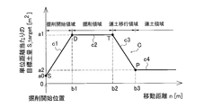
- FIG. 6 is a diagram showing an example of the target parameter data C. As shown in FIG.
- the target parameter data C defines the relationship between the movement distance n of the work vehicle 1 and the target parameter. In the present embodiment, the target parameter data C defines the relationship between the movement distance n of the work vehicle 1 and the target displacement Z_offset.
- the target parameter data C indicates the digging depth (target displacement) Z_offset in the vertical downward direction from the ground surface of the blade 18 as a dependent variable of the movement distance n in the horizontal direction of the work vehicle 1.
- the horizontal movement distance n of the work vehicle 1 is substantially the same value as the horizontal movement distance of the blade 18.
- the controller 26 determines the target displacement Z_offset from the movement distance n of the work vehicle 1 with reference to the target parameter data C shown in FIG.
- the target parameter data C includes start time data c1, digging time data c2, transition time data c3, and soil unloading time data c4.
- the start data c1 defines the relationship between the movement distance n in the excavation start area and the target displacement Z_offset.
- the digging start area is a range from the digging start point S to the steady digging start point D.
- a target displacement Z_offset that increases as the movement distance n increases is defined.
- the excavation data c2 defines the relationship between the movement distance n in the excavation area and the target displacement Z_offset.
- the excavation area is an area from the steady excavation start point D to the soil transfer start point T.
- the target displacement Z_offset is defined to a constant value.
- the excavation data c2 defines a constant target displacement Z_offset with respect to the movement distance n.
- the transition time data c3 defines the relationship between the movement distance n in the soil transportation transition area and the target displacement Z_offset.
- the soil transport transition area is an area from the steady excavation end point T to the soil transport start point P.
- the transition time data c3 defines a target displacement Z_offset that decreases as the movement distance n increases.
- the soil transportation time data c4 defines the relationship between the movement distance n in the soil transportation region and the target displacement Z_offset.
- the soil transportation area is an area starting from the soil transportation start point P.
- the target displacement Z_offset is defined to a constant value.
- the soil transportation time data c4 defines a constant target displacement Z_offset with respect to the movement distance n.
- the excavation area starts from the first start value b1 and ends at the first end value b2.
- the soil transportation area is started from the second start value b3.
- the first end value b2 is smaller than the second start value b3. Therefore, the excavation area is started when the movement distance n is smaller than the soil transportation area.
- the target displacement Z_offset in the excavation area is constant at the first target value a1.
- the target displacement Z_offset in the soil transportation area is constant at the second target value a2.
- the first target value a1 is larger than the second target value a2. Therefore, in the excavation area, a target displacement Z_offset larger than that of the soil transportation area is defined.
- the target displacement Z_offset at the digging start position is a start value a0.
- the start value a0 is smaller than the first target value a1.
- the start target value a0 is smaller than the second target value a2.
- FIG. 7 is a flowchart showing the process of determining the target displacement Z_offset.
- the traveling of the work vehicle 1 is assumed to be only forward.
- the determination process is started when the first operating device 25a moves to the forward position.
- the controller 26 determines whether the movement distance n is 0 or more and less than the first start value b1.
- the controller 26 gradually increases the target displacement Z_offset from the start value a0 according to the increase of the movement distance n.
- the start value a0 is a constant and is stored in the storage device 28.
- the start value a0 is preferably as small as possible so that the load on the blade 18 does not become excessively large at the start of excavation.
- the first start value b1 is calculated from the inclination c1 in the excavation start area shown in FIG. 6, the start value a0, and the first target value a1.
- the inclination c1 is a constant and is stored in the storage device 28.
- the inclination c1 is preferably a value that allows rapid transition from the digging start to the digging operation and that the load on the blade 18 does not become excessively large.
- step S203 the controller 26 determines whether the moving distance n is equal to or greater than the first start value b1 and less than the first end value b2.
- step S204 the controller 26 sets the target displacement Z_offset to the first target value a1.
- the first target value a1 is a constant and is stored in the storage device 28.
- the first target value a1 is preferably such a value that drilling can be efficiently performed and the load on the blade 18 does not become excessively large.
- step S205 the controller 26 determines whether the movement distance n is equal to or greater than the first end value b2 and less than the second start value b3.
- step S206 the controller 26 changes the target displacement Z_offset to the first target value a1 according to the increase of the movement distance n.
- the first end value b2 is a movement distance when the current amount of soil held by the blade 18 exceeds a predetermined threshold. Therefore, the controller 26 reduces the target displacement Z_offset from the first target value a1 when the current amount of soil held by the blade 18 exceeds a predetermined threshold.
- the predetermined threshold is determined based on, for example, the maximum capacity of the blade 18. For example, the current amount of soil held by the blade 18 may be determined by calculating the load on the blade 18 from the load. Alternatively, an image of the blade 18 may be acquired by a camera, and by analyzing the image, the present amount of soil held by the blade 18 may be calculated.
- a predetermined initial value is set as the first end value b2.
- the movement distance when the amount of soil held by the blade 18 exceeds a predetermined threshold is stored as an update value, and the first end value b2 is updated based on the stored update value.
- step S207 the controller 26 determines whether the moving distance n is equal to or greater than a second start value b3. When the movement distance n is equal to or larger than the second start value b3, the controller 26 sets the target displacement Z_offset to the second target value a2 in step S208.
- the second target value a2 is a constant and is stored in the storage device 28.
- the second target value a2 is preferably set to a value suitable for soil transportation work.
- the second start value b3 is obtained by calculation from the slope c2 in the soil transfer area shown in FIG. 6, the first target value a1, and the second target value a2.
- the slope c2 is a constant and is stored in the storage device 28.
- the inclination c2 is preferably a value such that the load can be quickly transferred from the digging operation to the soil transportation operation and the load on the blade 18 does not become excessively large.
- the start value a0, the first target value a1, and the second target value a2 may be changed according to the condition of the work vehicle 1 or the like.
- the first start value b1, the first end value b2, and the second start value b3 may be stored in the storage device 28 as constants.
- the height Z of the target design terrain 70 is determined by determining the target displacement Z_offset.
- step S107 shown in FIG. 4 the controller 26 controls the blade 18 toward the target design topography 70.
- the controller 26 generates a command signal to the work machine 13 so that the blade edge position of the blade 18 moves toward the target design topography 70 created in step S106.
- the generated command signal is input to the control valve 27. Thereby, the blade edge position P0 of the work machine 13 moves along the target design topography 70.
- the target displacement Z_offset between the current topography 50 and the target design topography 70 is large compared to the other areas. Thereby, the excavation work of the present topography 50 is performed in the excavation area.
- the target displacement Z_offset between the current topography 50 and the target design topography 70 is smaller compared to other areas. Thereby, in the soil transportation area, excavation of the ground is avoided, and the soil held by the blade 18 is transported.
- step S108 the controller 26 updates work site topography data.
- the controller 26 updates work site topography data with position data indicating the latest trajectory of the cutting edge position P0.
- the controller 26 may calculate the position of the bottom surface of the crawler belt 16 from the vehicle body position data and the vehicle body size data, and update the work site topography data with position data indicating the trajectory of the bottom surface of the crawler belt 16. In this case, updating of work site topography data can be performed immediately.
- the work site topography data may be generated from survey data measured by a surveying device outside the work vehicle 1.
- a surveying device outside the work vehicle 1.
- aviation laser surveying may be used as an external surveying instrument.
- the present topography 50 may be photographed by a camera, and work site topography data may be generated from image data obtained by the camera.
- aerial surveying with a UAV Unmanned Aerial Vehicle
- updating of work site topography data may be performed at predetermined intervals or at any time.
- the above process is performed when the work vehicle 1 is moving forward.
- the first controller 25a is in the forward position, the above process is performed.
- the work vehicle 1 moves backward a predetermined distance or more, the excavation start position, the movement distance n, and the amount of soil held by the blade 18 are initialized.
- the controller 26 updates the current topography 50 based on the updated work site topography data, and newly determines the target design topography 70 based on the updated current topography 50.
- the controller 26 then controls the blade 18 along the newly determined target design terrain 70. By repeating such processing, excavation is performed such that the current topography 50 approaches the final design topography 60.
- the work vehicle 1 is referred to as a single work path from when the work vehicle 1 moves forward and starts excavation until it switches to reverse.
- the work vehicle 1 moves backward to return to a position beyond the original digging start position, and the work vehicle 1 advances again to start digging, whereby the next work pass is executed.
- the work vehicle 1 starts excavation at a digging start position Ps1 separated by a predetermined distance from the dumping position and rearward.
- the controller 26 controls the work machine 13 in accordance with the target design topography 70-1 of the first work path.
- the work vehicle 1 moves backward and returns to a position beyond the original digging start position Ps1.
- the work vehicle 1 starts excavation at a work open position Ps2 separated by a predetermined distance from the original excavation start position Ps1 and rearward.
- the controller 26 controls the work machine 13 in accordance with the target design topography 70-2 of the second work path.
- the work vehicle 1 moves backward and returns to a position beyond the original digging start position Ps2.
- the work vehicle 1 starts excavation at a work open position Ps3 which is separated rearward from the original excavation start position P2 by a predetermined distance.
- the controller 26 controls the work implement 13 according to the target design topography 70-3 of the third work path. By repeating such an operation, the surface layer of the traveling path of the work vehicle 1 can be excavated.
- FIG. 9 is a flow chart showing processing for determining a recommended excavation start position.
- step S301 the controller 26 determines whether the current work path is the first work path. For example, the controller 26 may determine that the current work path is the first work path when the work is first performed after the engine of the work vehicle 1 is started. Alternatively, the controller 26 may determine the work path to be performed first as the first work path after the operator sets a certain position in the work site as the dumping position by the input device 25c. If the controller 26 determines that the current work path is the first work path, the process proceeds to step S302.
- step S302 the controller 26 determines the dumping position as a predetermined reference position. For example, the controller 26 acquires, as the dumping position, the operator's position in the work site set by the input device 25c. Alternatively, the controller 26 may determine a predetermined position preset in the present topography data as the dumping position.
- step S303 the controller 26 determines the sum of the distance d1 of the excavation area, the distance d2 of the excavation start area, and the distance d3 of the soil transportation transition area as the target return distance. As shown in FIG. 6, the controller 26 acquires, from the target parameter data C, the distance d1 of the excavation area, the distance d2 of the excavation start area, and the distance d3 of the soil transportation transition area.
- the distance d1 of the excavation area is the movement distance of the work vehicle 1 in the excavation area. In other words, the distance d1 of the excavation area is the distance from the start position to the end position of the excavation area.
- the distance d2 of the excavation start area is the movement distance of the work vehicle 1 in the excavation start area. In other words, the distance d2 of the excavation start area is the distance from the start position to the end position of the excavation start area.
- the distance d3 of the soil transportation transition area is the movement distance of the work vehicle 1 in the soil transportation area. In other words, the distance d3 of the soil transfer area is the distance from the start position to the end position of the soil transfer area.
- step S304 the controller 26 determines the recommended excavation start position of the first work path.
- the controller 26 determines the target return distance d1 + d2 + d3 from the dumping position and the position returned to the rear as the recommended digging start position Pr1 of the first work path.
- step S301 when the controller 26 determines that the current work path is not the first work path, the process proceeds to step S305. That is, when the current work path is a work path after the second work path, the process proceeds to step S305.
- step S305 the controller 26 determines the previous excavation start position as a predetermined reference position. The controller 26 determines the previous excavation start position acquired in the same manner as step S104 in FIG. 4 as a predetermined reference position.
- step S306 the controller 26 determines the sum of the distance d1 of the excavation area and the distance d2 of the excavation start area as the target return distance.
- step S307 the controller 26 determines a recommended excavation start position for the next work path.
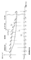
- the controller 26 determines the target return distance d1 + d2 from the previous digging start position, and the position returned to the rear as the digging start recommended position of the next work path. For example, as shown in FIG. 10, at the start of the second work pass, the controller 26 returns the target return distance d1 + d2 from the digging start position (for example, the digging start recommended position Pr1) of the first work pass to the rear. Are determined as the recommended drilling start position Pr2 of the second work path.
- the controller 26 excavates the position where the target return distance d1 + d2 has returned from the digging start position (for example, the digging start recommended position Pr2) of the second work path back to the rear. Determined as a start recommended position Pr3.
- step S308 the controller 26 displays the recommended excavation start position on the guide screen 80 on the display 25d.
- FIG. 9 is a view showing an example of the guide screen 80. As shown in FIG. As shown in FIG. 9, the guide screen 80 includes an icon 81 indicating the current position of the work vehicle 1, a current topography 50 around the work vehicle 1, and an icon 82 indicating a recommended excavation start position. The controller 26 outputs a display signal indicating the guide screen 80 to the display 25 d.
- the guide screen 80 is a side view in FIG. 11, as shown in FIG. 12, the guide screen 80 may be a top view. Alternatively, the guide screen 80 may be switchable between a side view and a top view. In the top guide screen 80, the current terrain 50 may be shown in different colors depending on its height. In FIG. 11, different colors are expressed depending on the type of hatching.
- the controller 26 determines the target return distance from the distance d1 of the excavation area, and excavates the target return distance from the predetermined reference position. Determined as a position. Since the distance d1 of the excavation area is a distance defined in the target parameter data as an area to be excavated, an appropriate position for the next excavation can be determined as the excavation start recommended position. Further, the controller 26 determines the target return distance from the predetermined reference position and the returned position as the next recommended excavation start position. Therefore, the calculation load on the controller 26 can be reduced.
- the controller 26 determines the sum of the distance d1 of the excavated area, the distance d2 of the excavated start area and the distance d3 of the soil transfer area as the target return distance, and the target return distance d1 from the dumping position. + d 2 + d 3,
- the returned position is determined as a digging start recommended position Pr 1 of the first work path. Therefore, not only the digging area but also the digging start area and the soil transfer area can be considered to determine an appropriate recommended digging start position.
- the controller 26 determines the sum of the distance d1 of the digging area and the distance d2 of the digging start area as the target return distance, and the target return distance d1 + from the previous digging start position. d2, the returned position is determined as a digging start recommended position for the next work path. Therefore, it is possible to determine an appropriate next recommended drilling start position in consideration of the drilling start region and the drilling region.
- the work vehicle 1 is not limited to a bulldozer, but may be another vehicle such as a wheel loader or a motor grader.
- the work vehicle 1 may be a remotely steerable vehicle. In that case, part of the control system 3 may be disposed outside the work vehicle 1.
- the controller 26 may be disposed outside the work vehicle 1.
- the controller 26 may be located in a control center remote from the work site.
- the controller 26 may have a plurality of controllers 26 separate from one another.
- the controller 26 may include a remote controller 261 disposed outside the work vehicle 1 and an on-board controller 262 mounted on the work vehicle 1.
- the remote controller 261 and the in-vehicle controller 262 may be able to communicate wirelessly via the communication devices 38 and 39. Then, part of the functions of the controller 26 described above may be performed by the remote controller 261, and the remaining functions may be performed by the onboard controller 262.
- the process of determining the target design topography 70 may be performed by the remote controller 261, and the process of outputting a command signal to the work machine 13 may be performed by the onboard controller 262.
- the operating devices 25a and 25b, the input device 25c, and the display 25d may be disposed outside the work vehicle 1. In that case, the driver's cab may be omitted from the work vehicle 1. Alternatively, the operation devices 25a and 25b, the input device 25c, and the display 25d may be omitted from the work vehicle 1.
- the work vehicle 1 may be operated only by the automatic control by the controller 26 without the operation by the operation devices 25a and 25b.
- the present topography 50 may be acquired by other devices as well as the position sensor 31 described above.
- the current terrain 50 may be acquired by the interface device 37 that receives data from an external device.
- the interface device 37 may wirelessly receive the present topography data measured by the external measurement device 41.
- the interface device 37 may be a reading device of a recording medium, and may receive current topography data measured by the external measuring device 41 via the recording medium.
- the target parameter data is not limited to the data shown in FIG. 6, and may be changed.
- the target parameter is a parameter related to the target excavation amount of the work machine 13 and may be another parameter without being limited to the target displacement of the above embodiment.
- FIG. 15 is a diagram showing another example of the target parameter data.
- the target parameter may be a target soil amount S_target for each point of flat terrain. That is, the target parameter may be the target soil amount S_target per unit distance.
- the controller 26 can calculate the target displacement Z_offset from the target soil amount S_target and the width of the blade 18.
- the target parameter may be a parameter different from the target soil amount S_target per unit distance.
- the target parameter may be a parameter indicating the target value of the load on the work machine 13 at each point.
- the controller 26 can calculate the target displacement Z_offset for each point from the target parameter. In that case, the controller 26 may increase the target displacement Z_offset in response to the increase of the target parameter.
- the target displacement Z_offset may be multiplied by a predetermined coefficient.
- a predetermined constant may be added to or subtracted from the target displacement Z_offset.
- the predetermined coefficient and the predetermined constant may be changed according to the change of the control mode.
- the controller 26 determines the recommended drilling start position, and displays the determined recommended drilling start position on the guide screen 80 on the display 25 d.
- the controller 26 may control the work vehicle 1 in accordance with the determined recommended excavation start position.
- the processes of steps S401 to S407 in FIG. 16 are the same as the processes of steps S301 to S307 in FIG.
- step S408 the controller 26 outputs a command signal so that the work machine 13 starts digging at the digging start recommended position.
- the controller 26 may move the work vehicle 1 to the excavation start recommended position and output a command signal so that the work machine 13 starts excavation at the excavation start recommended position.
- the display of the recommended excavation start position in step S308 and the control of the work vehicle 1 in step S408 may be performed together.
- a plurality of recommended excavation start positions may be displayed.
- icons 83 indicating a plurality of recommended excavation start positions including an icon 83 indicating a recommended excavation start position of the first work path and an icon 84 indicating a recommended excavation start position of the second work path. 85 may be displayed on the guide screen 80.
- the distance d1 of the excavated area, the distance d2 of the excavated start area, and the distance d3 of the soil transfer area is updated, and based on the updated value, the excavation of the next work path is started
- the recommended position may be determined. For example, as described above, when the first end value b2 of the excavation area is updated, the distance d2 of the excavation start area may be updated by the updated first end value b2.
- the controller 26 may determine the position set by the operation of the input device 25c by the operator as the digging start position.
- the method of determining the target return distance may be changed.
- the target return distance may be a function of parameters (such as d1, d2, d3, etc.) in the target parameter data other than those described in the above embodiments.
- the controller 26 may determine the target return distance by multiplying the digging area distance d1 by a predetermined coefficient.
- the controller 26 may determine the target return distance by adding a predetermined constant to the distance d1 of the excavation area.
- the controller 26 may acquire the present topography data within a range shorter than the predetermined topography recognition distance LA from the current position. That is, the controller 26 may acquire the present topography data for only a part of the plurality of reference points Pn.
- the controller 26 may determine the target design topography 70 within a range shorter than the predetermined topography recognition distance LA from the current position. That is, the controller 26 may determine the target design topography 70 for only a part of the plurality of reference points Pn.
Landscapes
- Engineering & Computer Science (AREA)
- Mining & Mineral Resources (AREA)
- Civil Engineering (AREA)
- General Engineering & Computer Science (AREA)
- Structural Engineering (AREA)
- Radar, Positioning & Navigation (AREA)
- Remote Sensing (AREA)
- Physics & Mathematics (AREA)
- Aviation & Aerospace Engineering (AREA)
- General Physics & Mathematics (AREA)
- Automation & Control Theory (AREA)
- Mechanical Engineering (AREA)
- Fluid Mechanics (AREA)
- Operation Control Of Excavators (AREA)
Abstract
Description
Z = Zn - Z_offset (1)
目標変位Z_offsetは、目標パラメータデータCを参照することで決定される。目標パラメータデータCは、記憶装置28に記憶されている。図6は、目標パラメータデータCの一例を示す図である。目標パラメータデータCは、作業車両1の移動距離nと、目標パラメータとの関係を規定する。本実施形態では、目標パラメータデータCは、作業車両1の移動距離nと、目標変位Z_offsetとの関係を規定する。
1 作業車両
28 記憶装置
26 コントローラ
25c 入力装置
31 位置センサ
25d ディスプレイ
Claims (20)
- 作業機を有する作業車両の制御システムであって、
前記作業車両の移動距離と、作業機の目標掘削量に関する目標パラメータとの関係を規定する目標パラメータデータを記憶している記憶装置と、
前記記憶装置と通信するコントローラと、
を備え、
前記目標パラメータデータは、所定の掘削領域内での前記作業車両の移動距離と前記目標パラメータとの関係を規定する掘削時データを含み、
前記コントローラは、
前記目標パラメータデータにおいて規定されている前記掘削領域の距離から目標戻り距離を決定し、
所定の基準位置から前記目標戻り距離、戻った位置を掘削開始推奨位置として決定する、
作業車両の制御システム。 - オペレータによる操作を示す操作信号を出力する入力装置をさらに備え、
前記コントローラは、前記入力装置から前記操作信号を受信し、
前記コントローラは、オペレータが前記入力装置によって設定した位置を、前記基準位置として決定する、
請求項1に記載の作業車両の制御システム。 - 前記作業車両の位置を示す位置信号を出力する位置センサをさらに備え、
前記コントローラは、
前記位置センサから前記位置信号を受信し、
前記位置信号から、今回の掘削開始位置を取得し、
前記今回の掘削開始位置を前記基準位置として決定し、
前記今回の掘削開始位置から前記目標戻り距離、戻った位置を次の掘削開始推奨位置として決定する、
請求項1に記載の作業車両の制御システム。 - 前記コントローラと通信するディスプレイをさらに備え、
前記コントローラは、前記作業車両の現在位置と、前記作業車両の周囲の地形と、前記掘削開始推奨位置とを含むガイド画面を示す表示信号を前記ディスプレイに出力する、
請求項1に記載の作業車両の制御システム。 - 前記コントローラは、前記作業車両を前記掘削開始推奨位置に移動させ、前記掘削開始推奨位置で前記作業機が掘削を開始するように、前記作業車両に指令信号を出力する、
請求項1に記載の作業車両の制御システム。 - 前記目標パラメータデータは、所定の移行範囲内での前記作業車両の移動距離と前記目標パラメータとの関係を規定する移行時データをさらに含み、
前記移行時データは、掘削される土量が徐々に減少又は増大するように、前記作業車両の移動距離と前記目標パラメータとの関係を規定し、
前記コントローラは、前記掘削範囲の距離と前記移行範囲の距離との和から前記目標戻り距離を決定する、
請求項1に記載の作業車両の制御システム。 - 前記作業車両の位置を示す位置信号を出力する位置センサをさらに備え、
前記コントローラは、
前記位置センサから前記位置信号を受信し、
作業対象の現況地形を示す現況地形データを取得し、
前記位置信号から前記作業車両の移動距離を取得し、
前記目標パラメータデータを参照して、前記作業車両の移動距離から前記目標パラメータを決定し、
前記目標パラメータに応じて前記現況地形を変位させた目標設計地形を決定し、
前記目標設計地形に従って前記作業機を制御する指令信号を出力する、
請求項1に記載の作業車両の制御システム。 - 作業機を有する作業車両の掘削開始推奨位置を決定するためにコントローラによって実行される方法であって、
前記作業車両の移動距離と、作業機の目標掘削量に関する目標パラメータとの関係を規定し、所定の掘削領域内での前記作業車両の移動距離と前記目標パラメータとの関係を示す掘削時データを含む、目標パラメータデータを参照することと、
前記目標パラメータデータにおいて規定されている前記掘削領域の距離から目標戻り距離を決定することと、
所定の基準位置から前記目標戻り距離、戻った位置を掘削開始推奨位置として決定すること、
を備える方法。 - オペレータによる操作を示す操作信号を入力装置から受信することと、
オペレータが前記入力装置によって設定した位置を、前記基準位置として決定すること、
をさらに備える請求項8に記載の方法。 - 前記作業車両の位置を示す位置信号を受信することと、
前記位置信号から、今回の掘削開始位置を取得することと、
前記今回の掘削開始位置を前記基準位置として決定することと、
をさらに備え、
前記掘削開始推奨位置を決定することは、前記今回の掘削開始位置から前記目標戻り距離、戻った位置を次の掘削開始推奨位置として決定することを含む、
請求項8に記載の方法。 - 前記作業車両の現在位置と、前記作業車両の周囲の地形と、前記掘削開始推奨位置とを含むガイド画面を示す表示信号をディスプレイに出力することをさらに備える、
請求項8に記載の方法。 - 前記作業車両を前記掘削開始推奨位置に移動させ、前記掘削開始推奨位置に前記作業機が掘削を開始するように、前記作業車両に指令信号を出力することをさらに備える、
請求項8に記載の方法。 - 前記目標パラメータデータは、所定の移行範囲内での前記作業車両の移動距離と前記目標パラメータとの関係を示す移行時データを含み、
前記移行時データは、掘削される土量が減少又は増大するように、前記作業車両の移動距離と前記目標パラメータとの関係を規定し、
前記目標戻り距離を決定することは、前記掘削範囲の距離と前記移行範囲の距離との和から前記目標戻り距離を決定することを含む、
請求項8に記載の方法。 - 前記作業車両の位置を示す位置信号を受信することと、
作業対象の現況地形を示す現況地形データを取得することと、
前記位置信号から前記作業車両の移動距離を取得することと、
前記目標パラメータデータを参照して、前記作業車両の移動距離から前記目標パラメータを決定することと、
前記目標パラメータに応じて前記現況地形を変位させた目標設計地形を決定することと、
前記目標設計地形に従って前記作業機を制御する指令信号を出力すること、
をさらに備える請求項8に記載の方法。 - 作業機と、
前記作業機を制御する指令信号を出力するコントローラと、
を備え、
前記コントローラは、前記作業車両の移動距離と、作業機の目標掘削量に関する目標パラメータとの関係を規定する目標パラメータデータを参照し、
前記目標パラメータデータは、所定の掘削領域内での前記作業車両の移動距離と前記目標パラメータとの関係を規定する掘削時データを含み、
前記コントローラは、
前記目標パラメータデータにおいて規定されている前記掘削領域の距離から目標戻り距離を決定し、
所定の基準位置から前記目標戻り距離、戻った位置を掘削開始推奨位置として決定する、
作業車両。 - オペレータによる操作を示す操作信号を出力する入力装置をさらに備え、
前記コントローラは、前記入力装置から前記操作信号を受信し、
前記コントローラは、オペレータが前記入力装置によって設定した位置を、前記基準位置として決定する、
請求項15に記載の作業車両。 - 前記作業車両の位置を示す位置信号を出力する位置センサをさらに備え、
前記コントローラは、
前記位置センサから前記位置信号を受信し、
前記位置信号から、今回の掘削開始位置を取得し、
前記今回の掘削開始位置を前記基準位置として決定し、
前記今回の掘削開始位置から前記目標戻り距離、戻った位置を次の掘削開始推奨位置として決定する、
請求項15に記載の作業車両。 - 前記コントローラと通信するディスプレイをさらに備え、
前記コントローラは、前記作業車両の現在位置と、前記作業車両の周囲の地形と、前記掘削開始推奨位置とを含むガイド画面を示す表示信号を前記ディスプレイに出力する、
請求項15に記載の作業車両。 - 前記コントローラは、前記作業車両を前記掘削開始推奨位置に移動させ、前記掘削開始推奨位置に前記作業機が掘削を開始するように、前記作業車両に指令信号を出力する、
請求項15に記載の作業車両。 - 前記目標パラメータデータは、所定の移行範囲内での前記作業車両の移動距離と前記目標パラメータとの関係を規定する移行時データを含み、
前記移行時データは、掘削される土量が徐々に減少又は増大するように、前記作業車両の移動距離と前記目標パラメータとの関係を規定し、
前記コントローラは、前記掘削範囲の距離と前記移行範囲の距離との和から前記目標戻り距離を決定する、
請求項15に記載の作業車両。
Priority Applications (4)
| Application Number | Priority Date | Filing Date | Title |
|---|---|---|---|
| AU2018325613A AU2018325613B2 (en) | 2017-08-29 | 2018-08-28 | Control System for Work Vehicle, Method, and Work Vehicle |
| CA3063665A CA3063665A1 (en) | 2017-08-29 | 2018-08-28 | Control system for work vehicle, method, and work vehicle |
| CN201880026591.6A CN110536989B (zh) | 2017-08-29 | 2018-08-28 | 作业车辆的控制系统、方法及作业车辆 |
| US16/612,231 US11180903B2 (en) | 2017-08-29 | 2018-08-28 | Control system for work vehicle, method, and work vehicle |
Applications Claiming Priority (2)
| Application Number | Priority Date | Filing Date | Title |
|---|---|---|---|
| JP2017164214A JP6910245B2 (ja) | 2017-08-29 | 2017-08-29 | 作業車両の制御システム、方法、及び作業車両 |
| JP2017-164214 | 2017-08-29 |
Publications (1)
| Publication Number | Publication Date |
|---|---|
| WO2019044822A1 true WO2019044822A1 (ja) | 2019-03-07 |
Family
ID=65527534
Family Applications (1)
| Application Number | Title | Priority Date | Filing Date |
|---|---|---|---|
| PCT/JP2018/031752 Ceased WO2019044822A1 (ja) | 2017-08-29 | 2018-08-28 | 作業車両の制御システム、方法、及び作業車両 |
Country Status (6)
| Country | Link |
|---|---|
| US (1) | US11180903B2 (ja) |
| JP (1) | JP6910245B2 (ja) |
| CN (1) | CN110536989B (ja) |
| AU (1) | AU2018325613B2 (ja) |
| CA (1) | CA3063665A1 (ja) |
| WO (1) | WO2019044822A1 (ja) |
Cited By (1)
| Publication number | Priority date | Publication date | Assignee | Title |
|---|---|---|---|---|
| CN116988790A (zh) * | 2023-07-17 | 2023-11-03 | 新驱动重庆智能汽车有限公司 | 多机车协同作业的矿区采矿方法 |
Families Citing this family (8)
| Publication number | Priority date | Publication date | Assignee | Title |
|---|---|---|---|---|
| JP7418948B2 (ja) * | 2018-03-28 | 2024-01-22 | 株式会社小松製作所 | 作業車両の制御システム、方法、及び作業車両 |
| JP2020033788A (ja) * | 2018-08-31 | 2020-03-05 | 株式会社神戸製鋼所 | 作業機械のブレード制御装置 |
| JP7244168B2 (ja) * | 2019-06-19 | 2023-03-22 | 株式会社小松製作所 | 作業機械を制御するためのシステム及び方法 |
| JP7287262B2 (ja) | 2019-12-18 | 2023-06-06 | コベルコ建機株式会社 | 遠隔操作システムおよび遠隔操作サーバ |
| JP7388954B2 (ja) | 2020-03-11 | 2023-11-29 | 株式会社小松製作所 | 操作ガイド装置 |
| US11920321B2 (en) * | 2020-03-30 | 2024-03-05 | Cnh Industrial America Llc | System and method for automatically performing an earthmoving operation |
| US20240194056A1 (en) * | 2022-12-08 | 2024-06-13 | Here Global B.V. | System and method for determining road work zone start location |
| CN116084481B (zh) * | 2023-01-09 | 2026-02-24 | 三一重机有限公司 | 一种挖掘机的作业方法、装置及系统 |
Citations (8)
| Publication number | Priority date | Publication date | Assignee | Title |
|---|---|---|---|---|
| JPH1091059A (ja) * | 1996-09-13 | 1998-04-10 | Taisei Corp | 基盤面仕上げ管理システム |
| JP2001303620A (ja) * | 2000-04-19 | 2001-10-31 | Ohbayashi Corp | 造成管理システム |
| US20140180444A1 (en) * | 2012-12-20 | 2014-06-26 | Caterpillar Inc. | System and Method for Modifying a Path for a Machine |
| US20160076223A1 (en) * | 2014-09-12 | 2016-03-17 | Caterpillar Inc. | System and Method for Controlling the Operation of a Machine |
| US20160077513A1 (en) * | 2014-09-12 | 2016-03-17 | Caterpillar Inc. | System and Method for Optimizing a Work Implement Path |
| US20160077514A1 (en) * | 2014-09-12 | 2016-03-17 | Caterpillar Inc. | System and Method for Optimizing a Work Implement Path |
| US20170009426A1 (en) * | 2015-07-09 | 2017-01-12 | Caterpillar Inc. | System and method for controlling operations of a machine |
| WO2017047826A1 (ja) * | 2016-09-30 | 2017-03-23 | 株式会社小松製作所 | 作業機械の表示システム及び作業機械 |
Family Cites Families (17)
| Publication number | Priority date | Publication date | Assignee | Title |
|---|---|---|---|---|
| ZA948824B (en) * | 1993-12-08 | 1995-07-11 | Caterpillar Inc | Method and apparatus for operating geography altering machinery relative to a work site |
| US5924493A (en) * | 1998-05-12 | 1999-07-20 | Caterpillar Inc. | Cycle planner for an earthmoving machine |
| JP2001123478A (ja) * | 1999-10-28 | 2001-05-08 | Hitachi Constr Mach Co Ltd | 自動運転ショベル |
| JP3787812B2 (ja) * | 2002-02-14 | 2006-06-21 | 清水建設株式会社 | 造成工事における重機の施工ナビゲーションシステム |
| NZ554197A (en) * | 2007-03-28 | 2009-07-31 | Caterpillar Trimble Control | Method and model for planning the path of a contour-shaping machine |
| US8639393B2 (en) * | 2010-11-30 | 2014-01-28 | Caterpillar Inc. | System for automated excavation planning and control |
| US8548690B2 (en) * | 2011-09-30 | 2013-10-01 | Komatsu Ltd. | Blade control system and construction machine |
| US20140012404A1 (en) * | 2012-07-06 | 2014-01-09 | Caterpillar Inc. | Methods and systems for machine cut planning |
| JP5285805B1 (ja) * | 2012-10-26 | 2013-09-11 | 株式会社小松製作所 | ブレード制御装置、作業機械及びブレード制御方法 |
| US9014922B2 (en) | 2012-12-20 | 2015-04-21 | Caterpillar Inc. | System and method for optimizing a cut location |
| US9014925B2 (en) * | 2013-03-15 | 2015-04-21 | Caterpillar Inc. | System and method for determining a ripping path |
| US9891605B2 (en) * | 2014-08-06 | 2018-02-13 | Caterpillar Inc. | Grade control cleanup pass using volume constraints |
| US9506224B2 (en) * | 2014-08-06 | 2016-11-29 | Caterpillar Inc. | Grade control cleanup pass using splines |
| US20160040388A1 (en) * | 2014-08-06 | 2016-02-11 | Caterpillar Inc. | Grade Control Cleanup Pass Using Cost Optimization |
| US9260837B1 (en) * | 2014-09-10 | 2016-02-16 | Caterpillar Inc. | Intelligent pass jump control |
| US9256227B1 (en) * | 2014-09-12 | 2016-02-09 | Caterpillar Inc. | System and method for controlling the operation of a machine |
| US10407872B2 (en) * | 2017-08-15 | 2019-09-10 | Caterpillar Inc. | System and method for controlling earthmoving machines |
-
2017
- 2017-08-29 JP JP2017164214A patent/JP6910245B2/ja active Active
-
2018
- 2018-08-28 CN CN201880026591.6A patent/CN110536989B/zh active Active
- 2018-08-28 WO PCT/JP2018/031752 patent/WO2019044822A1/ja not_active Ceased
- 2018-08-28 AU AU2018325613A patent/AU2018325613B2/en active Active
- 2018-08-28 US US16/612,231 patent/US11180903B2/en active Active
- 2018-08-28 CA CA3063665A patent/CA3063665A1/en not_active Withdrawn
Patent Citations (8)
| Publication number | Priority date | Publication date | Assignee | Title |
|---|---|---|---|---|
| JPH1091059A (ja) * | 1996-09-13 | 1998-04-10 | Taisei Corp | 基盤面仕上げ管理システム |
| JP2001303620A (ja) * | 2000-04-19 | 2001-10-31 | Ohbayashi Corp | 造成管理システム |
| US20140180444A1 (en) * | 2012-12-20 | 2014-06-26 | Caterpillar Inc. | System and Method for Modifying a Path for a Machine |
| US20160076223A1 (en) * | 2014-09-12 | 2016-03-17 | Caterpillar Inc. | System and Method for Controlling the Operation of a Machine |
| US20160077513A1 (en) * | 2014-09-12 | 2016-03-17 | Caterpillar Inc. | System and Method for Optimizing a Work Implement Path |
| US20160077514A1 (en) * | 2014-09-12 | 2016-03-17 | Caterpillar Inc. | System and Method for Optimizing a Work Implement Path |
| US20170009426A1 (en) * | 2015-07-09 | 2017-01-12 | Caterpillar Inc. | System and method for controlling operations of a machine |
| WO2017047826A1 (ja) * | 2016-09-30 | 2017-03-23 | 株式会社小松製作所 | 作業機械の表示システム及び作業機械 |
Cited By (1)
| Publication number | Priority date | Publication date | Assignee | Title |
|---|---|---|---|---|
| CN116988790A (zh) * | 2023-07-17 | 2023-11-03 | 新驱动重庆智能汽车有限公司 | 多机车协同作业的矿区采矿方法 |
Also Published As
| Publication number | Publication date |
|---|---|
| CN110536989B (zh) | 2022-02-18 |
| US20210148090A1 (en) | 2021-05-20 |
| JP2019039278A (ja) | 2019-03-14 |
| US11180903B2 (en) | 2021-11-23 |
| AU2018325613B2 (en) | 2020-11-26 |
| JP6910245B2 (ja) | 2021-07-28 |
| AU2018325613A1 (en) | 2019-11-28 |
| CN110536989A (zh) | 2019-12-03 |
| CA3063665A1 (en) | 2019-12-06 |
Similar Documents
| Publication | Publication Date | Title |
|---|---|---|
| AU2019204212B2 (en) | Control system for work vehicle, method for setting trajectory of work implement, and work vehicle | |
| AU2018325613B2 (en) | Control System for Work Vehicle, Method, and Work Vehicle | |
| AU2017272278B2 (en) | Control system for work vehicle, and method for setting trajectory of work implement | |
| JP6878317B2 (ja) | 作業車両の制御システム、及び作業機の軌跡設定方法 | |
| JP6910450B2 (ja) | 作業車両の制御システム、方法、及び作業車両 | |
| JP7133539B2 (ja) | 作業車両の制御システム、作業機の軌跡設定方法、及び作業車両 | |
| JP6861598B2 (ja) | 作業車両の制御システム、方法、及び作業車両 | |
| WO2019044821A1 (ja) | 作業車両の制御システム、方法、及び作業車両 | |
| WO2018159435A1 (ja) | 作業車両の制御システム、作業機の軌跡設定方法、及び作業車両 | |
| CN110114535A (zh) | 作业车辆的控制系统、工作装置的轨迹设定方法以及作业车辆 | |
| WO2018216470A1 (ja) | 作業車両の制御システム、方法、及び作業車両 | |
| WO2019187770A1 (ja) | 作業車両の制御システム、方法、及び作業車両 | |
| JP2018021428A (ja) | 作業車両の制御システム、制御方法、及び作業車両 | |
| US11414840B2 (en) | Control system for work machine, method, and work machine | |
| JP7379281B2 (ja) | 作業機械を制御するためのシステム、方法、および作業機械 | |
| WO2022163272A1 (ja) | 作業機械を制御するためのシステム、方法、および作業機械 |
Legal Events
| Date | Code | Title | Description |
|---|---|---|---|
| 121 | Ep: the epo has been informed by wipo that ep was designated in this application |
Ref document number: 18851953 Country of ref document: EP Kind code of ref document: A1 |
|
| ENP | Entry into the national phase |
Ref document number: 2018325613 Country of ref document: AU Date of ref document: 20180828 Kind code of ref document: A |
|
| NENP | Non-entry into the national phase |
Ref country code: DE |
|
| 122 | Ep: pct application non-entry in european phase |
Ref document number: 18851953 Country of ref document: EP Kind code of ref document: A1 |