WO2019044809A1 - 鉄道車両用ダンパおよび鉄道車両用制振装置 - Google Patents
鉄道車両用ダンパおよび鉄道車両用制振装置 Download PDFInfo
- Publication number
- WO2019044809A1 WO2019044809A1 PCT/JP2018/031702 JP2018031702W WO2019044809A1 WO 2019044809 A1 WO2019044809 A1 WO 2019044809A1 JP 2018031702 W JP2018031702 W JP 2018031702W WO 2019044809 A1 WO2019044809 A1 WO 2019044809A1
- Authority
- WO
- WIPO (PCT)
- Prior art keywords
- damper
- damping
- valve
- damping force
- speed
- Prior art date
- Legal status (The legal status is an assumption and is not a legal conclusion. Google has not performed a legal analysis and makes no representation as to the accuracy of the status listed.)
- Ceased
Links
Images



Classifications
-
- B—PERFORMING OPERATIONS; TRANSPORTING
- B61—RAILWAYS
- B61F—RAIL VEHICLE SUSPENSIONS, e.g. UNDERFRAMES, BOGIES OR ARRANGEMENTS OF WHEEL AXLES; RAIL VEHICLES FOR USE ON TRACKS OF DIFFERENT WIDTH; PREVENTING DERAILING OF RAIL VEHICLES; WHEEL GUARDS, OBSTRUCTION REMOVERS OR THE LIKE FOR RAIL VEHICLES
- B61F5/00—Constructional details of bogies; Connections between bogies and vehicle underframes; Arrangements or devices for adjusting or allowing self-adjustment of wheel axles or bogies when rounding curves
- B61F5/02—Arrangements permitting limited transverse relative movements between vehicle underframe or bolster and bogie; Connections between underframes and bogies
- B61F5/22—Guiding of the vehicle underframes with respect to the bogies
- B61F5/24—Means for damping or minimising the canting, skewing, pitching, or plunging movements of the underframes
-
- B—PERFORMING OPERATIONS; TRANSPORTING
- B61—RAILWAYS
- B61F—RAIL VEHICLE SUSPENSIONS, e.g. UNDERFRAMES, BOGIES OR ARRANGEMENTS OF WHEEL AXLES; RAIL VEHICLES FOR USE ON TRACKS OF DIFFERENT WIDTH; PREVENTING DERAILING OF RAIL VEHICLES; WHEEL GUARDS, OBSTRUCTION REMOVERS OR THE LIKE FOR RAIL VEHICLES
- B61F9/00—Rail vehicles characterised by means for preventing derailing, e.g. by use of guide wheels
-
- F—MECHANICAL ENGINEERING; LIGHTING; HEATING; WEAPONS; BLASTING
- F16—ENGINEERING ELEMENTS AND UNITS; GENERAL MEASURES FOR PRODUCING AND MAINTAINING EFFECTIVE FUNCTIONING OF MACHINES OR INSTALLATIONS; THERMAL INSULATION IN GENERAL
- F16F—SPRINGS; SHOCK-ABSORBERS; MEANS FOR DAMPING VIBRATION
- F16F9/00—Springs, vibration-dampers, shock-absorbers, or similarly-constructed movement-dampers using a fluid or the equivalent as damping medium
- F16F9/32—Details
- F16F9/44—Means on or in the damper for manual or non-automatic adjustment; such means combined with temperature correction
- F16F9/46—Means on or in the damper for manual or non-automatic adjustment; such means combined with temperature correction allowing control from a distance, i.e. location of means for control input being remote from site of valves, e.g. on damper external wall
Definitions
- the present invention relates to a damper for a railway vehicle and a damping device for a railway vehicle.
- this type of rail vehicle damper is interposed between the car body and the bogie of the rail car, as disclosed in, for example, JPH 10-244940A, so that the rail car can move to the left and right with respect to the traveling direction of the car body. It is used as a railway vehicle damping device that suppresses directional vibration.
- a damping device for a railway vehicle includes an actuator or a semi-active damper in addition to the damper for a railway vehicle, and suppresses the vibration of the vehicle body by the force exerted by the actuator or the like.
- the damper for a railway vehicle is the damper for a railway vehicle. To exert a high damping force to prevent derailment.
- the force of the actuator etc. is optimally controlled to suppress the vibration of the vehicle body, so if the damping force generated by the railway vehicle damper in normal time is high, It interferes with the damping effect of the vehicle body.
- this invention aims at provision of the damper for rail vehicles, and the damping device for rail vehicles which can prevent a wheel removal effectively at the time of an earthquake, and do not impair the damping effect of a vehicle body at normal times.
- the railway vehicle damper includes a cylinder, a rod inserted into the cylinder, and a piston slidably inserted into the cylinder and coupled to the rod to divide the cylinder into a rod side chamber and a piston side chamber.
- Elastic body, and a damping part that exerts a damping force when expanding and contracting the elastic body, and the damping force more than the damping force required for preventing the derailment of the railway vehicle when the expansion and contraction speed becomes the first speed or more It exerts a damping force of 10 kN or less when the expansion and contraction speed is less than the second speed which is lower than the first speed.
- the vibration of the vehicle body can be rapidly reduced, and wheel removal can be effectively suppressed.
- a damping force of 10 kN or less is exerted, so that the damping effect of the damping force exerted by the semi-active damper and the actuator is not adversely affected.
- the damping device for railway vehicles has at least one of one or more dampers for railway vehicles and at least one of an actuator and a semi-active damper, and a total sum of damping forces exerted when the extension speed is equal to or higher than the first speed.
- the required damping force is required per truck per earthquake.
- the damper for railway vehicles installed for one bogie, the actuator, and the semi-active damper cooperate with each other to obtain the necessary damping force or more required for preventing wheel removal. Since the damping force is exerted, the vibration of the vehicle body B can be rapidly reduced even if an earthquake occurs while the railway vehicle is traveling, and wheel removal can be effectively suppressed.
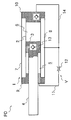
- FIG. 1 is a view showing a railway vehicle damping device in a state of being mounted on a railway vehicle.
- FIG. 2 is a hydraulic circuit diagram of a railcar damper according to an embodiment.
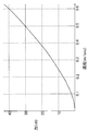
- FIG. 3 is a view showing a damping force characteristic which is a characteristic of the damping force with respect to the expansion and contraction speed of the railcar damper according to the embodiment.
- FIG. 4 is a hydraulic circuit diagram of the semi-active damper in one embodiment.
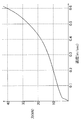
- FIG. 5 is a view showing a damping force characteristic which is a characteristic of the damping force with respect to the extension and contraction speed of the semi-active damper in the embodiment.
- FIG. 6 is a hydraulic circuit diagram of an actuator damper according to an embodiment.
- Vibration damping device S for railway vehicles in the first embodiment is used for damping vehicle body B of a railway vehicle.
- the damping device S for a railway vehicle according to this embodiment includes a damper PD for a railway vehicle and a semi-active damper AD interposed between a vehicle body B and a bogie T.
- the rail vehicle damper PD and the semi-active damper AD are connected to a pin P suspended below the vehicle body B, and are interposed in parallel between the vehicle body B and the truck T in pairs. ing.
- the carriage T rotatably holds the wheel W, and a suspension spring CS is interposed between the vehicle body B and the carriage T, and the vehicle body B is elastically supported from the lower side. Horizontal movement is allowed.
- the railway vehicle damper PD includes an expandable body 1 and a damping portion V.
- the expandable body 1 is a cylinder 2 connected to a car body B of a railway vehicle, a piston 3 slidably inserted into the cylinder 2 to divide the inside of the cylinder 2 into a rod side chamber 5 and a piston side chamber 6, and a cylinder 2
- a rod 4 is inserted inside and connected to the piston 3 and the carriage T, and a tank 8 provided between the cylinder 2 and an outer cylinder 7 covering the outer periphery of the cylinder 2.
- the cylinder 2 and the outer cylinder 7 are both cylindrical, and the opening on the left end side in FIG. 2 is annular and closed by the rod guide 9 fitted to both, and the cylinder 2 and the outer cylinder 7 in FIG. The opening on the right end side is closed by the bottom cap 10 fitted to both. Further, a rod 4 movably inserted into the cylinder 2 is slidably inserted into the rod guide 9, and axial movement of the rod 4 is guided by the rod guide 9. Further, one end of the rod 4 protrudes out of the cylinder 2 through the rod guide 9, and the other end in the cylinder 2 is connected to the piston 3 slidably inserted in the cylinder 2.
- the rod side chamber 5 and the piston side chamber 6 partitioned by the piston 3 in the cylinder 2 are filled with the hydraulic oil as the hydraulic fluid, and the tank 8 stores the hydraulic oil. It is filled with gas.
- the inside of the tank 8 is not particularly required to be compressed and filled with gas to be pressurized.
- the working fluid other fluids may be used besides the working oil.
- the telescopic body 1 is not shown, but the rod 4 is connected to one of the bogie and the vehicle body of the railway vehicle, and the cylinder 2 is connected to the other of the bogie and the vehicle body, and interposed between the bogie and the vehicle body. Since the expandable body 1 is set to a single rod type, it is easier to secure the stroke length compared to a double rod type cylinder device, the overall length of the expandable body 1 is shortened, and the mountability to a railway vehicle is improved Do.
- the railcar damper PD includes a straightening passage 13 that allows only the flow from the piston side chamber 6 to the rod side chamber 5.
- the straightening passage 13 may be provided other than the piston 3.
- the rail vehicle damper PD includes a suction passage 14 that allows only the flow from the tank 8 toward the piston side chamber 6.
- the rail vehicle damper PD includes a discharge passage 11 communicating the rod side chamber 5 with the tank 8 and a throttle 12 provided in the discharge passage 11, and the discharge passage 11 and the throttle 12 reduce the damping portion V. Configured.
- the rail vehicle damper PD of this embodiment when the expandable body 1 is expanded by receiving an external force, hydraulic oil is pushed out from the rod side chamber 5 to be compressed to the tank 8 through the discharge passage 11. Then, hydraulic oil is supplied from the tank 8 to the piston side chamber 6 to be expanded through the suction passage 14. Therefore, at the time of the extension operation, the railcar damper PD exerts a damping force by giving resistance to the flow of the hydraulic oil passing through the discharge passage 11 with the throttle 12.
- the rail vehicle damper PD of this embodiment when the expandable body 1 contracts due to an external force, the hydraulic oil moves from the piston side chamber 6 compressed via the straightening passage 13 to the rod side chamber 5. Further, at the time of contraction of the stretchable body 1, the rod 4 intrudes into the cylinder 2, so the volume of hydraulic oil which the rod 4 intrudes into the cylinder 2 becomes excessive in the cylinder 2 to the tank 8 through the discharge passage 11. Exhausted. Therefore, at the time of the contraction operation, the rail vehicle damper PD exerts a damping force by giving resistance to the flow of the hydraulic oil passing through the discharge passage 11 with the throttle 12.
- the cross-sectional area of the rod 4 is half of the cross-sectional area of the piston 3, and the pressure receiving area on the rod side chamber 5 side of the piston 3 is half on the pressure receiving area on the piston side chamber 6 side. It has become. Accordingly, the flow rate discharged from the inside of the cylinder 2 to the tank 8 through the discharge passage 11 becomes equal at the time of expansion and contraction of the expandable body 1.
- the damping force exerted by the railcar damper PD is obtained by multiplying the pressure loss generated by the throttle 12 with respect to the passing flow rate of the hydraulic oil discharged from the cylinder 2 toward the tank 8 multiplied by half of the sectional area of the piston 3 It becomes a value. Therefore, the rail vehicle damper PD can exert equal damping force as long as the moving speed of the piston 3 is the same on both sides of expansion and contraction.
- the diaphragm 12 when the expansion / contraction speed of the expansion / contraction body 1 becomes equal to or more than the first speed v1, the diaphragm 12 causes the railcar damper PD to exert a damping force for preventing derailing.
- the damping device S for a railway vehicle is necessary for preventing derailing of the railway vehicle at the time of an earthquake around one bogie T It suffices to exert a damping force.
- the damping device S for rail vehicles of this example is provided with the damper PD for rail vehicles and the semi-active damper AD, and the sum total of the damping force exerted when each expands and contracts at the first speed v1 is the damping force It should just be more than.
- the rail vehicle damper PD and the semi-active damper AD equally share the required damping amount when expanding and contracting at the first speed v1, and half of the required damping force is damped. Demonstrate power.
- the first speed v1 is set to the extension / contraction speed of the expansion / contraction body 1 which may cause the railway vehicle to derail, and is set to 0.6 m / sec in this example, and the necessary damping force is 80 kN.
- the railcar damper PD is set so that the expansion / contraction speed of the cylinder device C1 exhibits a damping force of 40 kN at 0.6 m / sec.
- the sum of the damping forces of the railcar damper PD and the semi-active damper AD may be equal to or greater than the necessary damping force.
- the railcar damper PD and the semiactive damper AD have the first speed v1. In the above, one half of the required damping force is output, but the sharing ratio of the required damping force may be changed.
- the damping force output by the rail vehicle damper PD and the semi active damper AD at the first speed v1 It is sufficient to set so that the sum of the above becomes equal to or more than the necessary damping force.
- the necessary damping force may be set to a value suitable for a railway vehicle.
- the throttle 12 causes the railway vehicle damper PD to exhibit a damping force of 10 kN or less when the expansion and contraction speed of the expandable body 1 is less than the second speed v2 lower than the first speed v1.
- the second velocity v2 is set to the expansion / contraction speed of the expansion / contraction body 1 that will reach when an earthquake occurs, is set to 0.2 m / sec, and the diaphragm 12 is expanded / contracted When the expansion and contraction speed of the body 1 is less than 0.2 m / sec, a damping force of 10 kN or less is generated in the rail vehicle damper PD.
- the characteristic (damping force characteristic) of the damping force with respect to the expansion and contraction speed of the rail vehicle damper PD has a square characteristic peculiar to the orifice and 0.2 m / second speed v 2. In the range of less than sec, it becomes less than 10 kN, and when it becomes 0.6 m / sec or more which is the first velocity v1, it becomes 40 kN or more.
- the diaphragm 12 in the damping part V can exhibit a damping force higher than the damping force that can prevent the wheel release when the expansion / contraction speed is less than the second speed v2 and the damping force becomes 10 kN and the expansion / contraction speed becomes the first speed v1 or more. It can be replaced by a damping valve other than 12.
- the damper PD for rail vehicles is a uniflow type damper in which the flow of hydraulic fluid is one way as described above
- the damping portion V when it is set as a biflow type damper, the damping portion V is It may be configured to include a damping passage that resists the flow of hydraulic fluid from the rod side chamber 5 to the piston side chamber 6 and a damping passage that resists the flow of hydraulic fluid from the piston side chamber 6 to the tank 8.
- the damper for rail vehicle when the rail vehicle damper PD is a uniflow type damper, the damper for rail vehicle may be configured as long as the damping portion V may be configured by one discharge passage 11 and one throttle 12 or damping valve. PD is cheap.
- the railcar damper PD can be made inexpensive as compared to a damping valve that resists the flow of hydraulic fluid with a valve body or a spool. it can.
- the first velocity v1 is set to 0.6 m / sec
- the second velocity v2 is set to 0.2 m / sec, but both may be set to other numerical values.
- the necessary damping force may be set to a value that can prevent derailing in accordance with the specification of the railway vehicle.
- the semi-active damper AD as shown in FIG. 4, has a first passage 15 communicating the rod side chamber 5 and the piston side chamber 6 with respect to the configuration of the rail vehicle damper PD, and a first passage 15 provided in the first passage 15
- An on-off valve 16, a second passage 17 for communicating the piston side chamber 6 with the tank 8, and a second on-off valve 18 provided in the second passage 17 are provided. 19 and a damping force switching unit 20 are provided.
- each part of the semi-active damper AD different from the rail vehicle damper PD will be described.
- the first on-off valve 16 is an electromagnetic on-off valve, and has a communication position for connecting the rod side chamber 5 and the piston side chamber 6, and a blocking position for disconnecting the rod side chamber 5 and the piston side chamber 6 Sometimes, the first passage 15 is opened to communicate the rod side chamber 5 with the piston side chamber 6.
- the second on-off valve 18 is an electromagnetic on-off valve, and has a communication position for communicating the piston side chamber 6 with the tank 8 and a blocking position for breaking the communication between the piston side chamber 6 and the tank 8
- the second passage 17 is opened to communicate the piston side chamber 6 with the tank 8.
- the discharge passage 11 is provided with a variable relief valve 19 capable of changing the valve opening pressure.
- the variable relief valve 19 in this example is a proportional electromagnetic relief valve, which can adjust the valve opening pressure according to the amount of supplied current, and when the amount of current is maximized, the valve opening pressure is minimized. If there is no supply, the valve opening pressure is maximized.
- the damping force switching unit 20 branches from the damping valve 21 provided downstream of the variable relief valve 19 in the discharge passage 11 and the upstream of the damping valve 21 in the discharge passage 11 and bypasses the damping valve 21 to be a tank.
- a bypass passage 22 communicated with the valve 8 and a switching valve 23 provided between the variable relief valve 19 and the damping valve 21 in the discharge passage 11 are provided.
- the damping valve 21 is an orifice having the same flow rate pressure loss characteristic as the throttle 12. And, when the hydraulic fluid of the flow rate discharged to the tank 8 from inside the cylinder 2 through the discharge passage 11 when the expansion and contraction body 1 expands and contracts at the second speed v 2 or more, the pressure loss at the same flow rate is the same.
- the pressure loss is set to be larger than the pressure loss that occurs when the hydraulic oil passes through the variable relief valve 19 when it is not energized.
- the flow rate of the hydraulic oil passing through the discharge passage 11 is a value obtained by subtracting the cross-sectional area of the rod 4 from the cross-sectional area of the piston 3 and the movement amount of the piston 3.
- the switching valve 23 is provided in the discharge passage 11 at a first position 23 b for communicating the downstream of the variable relief valve 19 to the bypass 22 and at a second position 23 c for connecting the downstream of the variable relief valve 19 to the damping valve 21.
- a pilot passage 23e operated to take the second position 23c.
- the switching valve 23 is configured to generate a pressure loss with respect to the passage of hydraulic fluid when the first position 23 b is taken.
- the switching valve 23 selects the detour 22 and causes the hydraulic fluid to flow to the tank 8 without passing through the damping valve 21.
- the switching valve 23 selects the damping valve 21 when the flow rate of the hydraulic fluid flowing through the discharge passage 11 is equal to or higher than the set flow rate, and flows the hydraulic fluid passing through the variable relief valve 19 to the tank 8 via the damping valve 21 .
- the switching valve 23 selects the bypass path 22 when the expandable body 1 expands and contracts at less than the second speed v2, and the attenuation valve 21 when the expandable body 1 expands and contracts at the second speed v2 or more. select. Since the bypass passage 22 passes the hydraulic oil with little resistance, the pressure loss occurring at the first position 23 b and the bypass passage 22 is set to be very small compared to the pressure loss occurring at the variable relief valve 19. ing.
- the damping force switching unit 20 causes only a small pressure loss compared to the variable relief valve 19 when the expansion and contraction speed of the expansion and contraction body 1 is less than the second speed v2, and the expansion and contraction speed of the expansion and contraction body 1 is the second speed v2 When it is above, the damping valve 21 causes a pressure loss larger than that of the variable relief valve 19.
- the semi-active damper AD of this example when the first on-off valve 16 and the second on-off valve 18 take the blocking position, the rod side chamber 5 is compressed when it receives an external force and expands. The hydraulic oil is pushed out to the tank 8 through the discharge passage 11. Then, hydraulic oil is supplied from the tank 8 to the piston side chamber 6 to be expanded through the suction passage 14.
- the semi-active damper AD resists the flow of hydraulic oil by the variable relief valve 19 and exerts a damping force for suppressing the extension.
- the semi-active damper AD applies resistance to the flow of hydraulic oil by the damping valve 21 in the variable relief valve 19 and damping force switching unit 20. Exerts a damping force that suppresses elongation.
- the semi-active damper AD applies resistance to the flow of hydraulic oil by the damping valve 21 in the variable relief valve 19 and damping force switching unit 20. Exerts a damping force that suppresses contraction.
- the first on-off valve 16 and the second on-off valve 18 both take off positions when deenergized, and in the event of power supply failure, the semi-active damper AD of this example always dampens against expansion and contraction as described above Function as a passive damper.
- the rod side chamber 5 and the piston side chamber 6 are disconnected.
- the side chamber 6 and the tank 8 are in communication via the second passage 17.
- the expandable body 1 receives an external force and is expanded, the hydraulic oil is discharged from the rod side chamber 5 to the discharge passage 11 as the rod side chamber 5 is contracted, and exerts a damping force against the expansion as described above.
- this semi-active damper AD does not exert a damping force.
- this semi-active damper AD can function as a one-way damper that selects either the extension or the contraction to exhibit a damping force.
- Damping force characteristics at the time of non-energization in the semi-active damper AD configured in this way are as shown in FIG.
- the damping force characteristic of the semi-active damper AD at the time of non-energization is that the variable relief valve 19 exerts a damping force when the expansion and contraction speed of the expandable body 1 is less than the second speed v2 (0.2 m / sec in this example).
- the damping force characteristic of the variable relief valve 19 appears as shown in FIG.
- the switching valve 23 is switched to the second position 23c, and the hydraulic oil passes through the damping valve 21.
- hydraulic oil having a flow rate equal to or higher than the set flow rate flows through the damping valve 21, and in this state, the pressure loss in the damping valve 21 is larger than the pressure loss in the variable relief valve 19. Therefore, when the expansion / contraction speed of the expansion / contraction body 1 becomes 0.2 m / sec or more which is the second speed v2, the damping force characteristic of the semi-active damper AD exhibits the characteristic of the damping valve 21. Specifically, as shown in FIG.
- the square characteristic of the orifice appears, and the high damping force of the semi-active damper AD is exhibited. Note that if the valve opening pressure of the variable relief valve 19 is adjusted, the expansion / contraction speed of the stretchable body 1 in which only the characteristics of the variable relief valve 19 appear is within the range below the characteristic line of FIG. The damping force of the semi-active damper AD can be adjusted up and down.
- the damping force of the semi-active damper AD is reached when the expansion speed of the expandable body 1 reaches 0.6 m / sec, which is the first speed v1. It will be 40kN.
- the semi-active damper AD functions as a passive damper when the first on-off valve 16 and the second on-off valve 18 are in the blocking position, and variable relief when the expansion and contraction speed of the expansion and contraction body 1 is less than the second speed v2
- the damping force can be adjusted.
- the semi-active damper AD when the first on-off valve 16 and the second on-off valve 18 are in the blocking position, the semi-active damper AD functions as a passive damper, and the damping valve 21 is operated when the expansion and contraction speed of the expandable body 1 becomes equal to or higher than the second speed v2. The generated damping force is high.
- the semi-active damper AD is in a mode that exerts a damping force only to either the extension or the contraction. Therefore, for example, if this mode is selected, if the direction in which the damping force is exerted is the direction in which the vehicle body is excited by the vibration of the bogie of the railway vehicle, the damping force is not output in such a direction.
- the semi-active damper AD can be used as a one-effect damper.
- this semi-active damper AD semi-active control based on Kalnop's skyhook theory can be easily realized, so the semi-active damper AD can function as a skyhook semi-active damper.
- the variable relief valve 19 exerts a damping force when the expansion and contraction speed of the expandable body 1 is less than the second speed v2. Adjustment of the damping force is possible.
- the semi-active damper AD is damped by the damping valve 21 when the expansion and contraction speed of the expandable body 1 becomes equal to or higher than the second speed v2. Demonstrate high damping force.
- the first on-off valve 16 and the second on-off valve 18 take the shutoff position.
- the active damper AD functions as a passive damper. In this state, the hydraulic fluid is always discharged from the inside of the cylinder 2 when the expandable body 1 expands and contracts, and the discharged hydraulic fluid flows into the tank 8 through the discharge passage 11.
- the semi-active damper AD exhibits damping force, but the truck vibrates violently due to a large earthquake and the relative speed with the vehicle body is fast, and the expansion and contraction speed of the expansion and contraction body 1 is the second speed v2
- the semi-active damper AD exerts a damping force by the damping valve 21, and therefore, exerts a higher damping force than the normal case in which the damping force is exerted by the variable relief valve 19 alone.
- the dampers PD for rail vehicles and the semi-active dampers AD cooperate with each other so that the damping device S for railway vehicles configured as described above Demonstrate a damping force greater than the required damping force required for prevention. Therefore, even if an earthquake occurs while the railcar is traveling, the dampers PD for railcars and the damping device S for railcars can reduce the vibration of the vehicle body B quickly, and can effectively suppress wheel removal.
- the damper PD for rail vehicles exerts only a damping force of less than 10 kN when the expansion and contraction speed of the expandable body 1 is less than the second speed v2, the damping effect of the vehicle body B by the damping force exerted by the semi-active damper AD Not adversely affect.
- the railcar damper PD and the railcar damping device S can effectively prevent derailing during an earthquake and do not impair the damping effect of the vehicle body at normal times.
- the rail vehicle damper PD of this example includes the tank 8, the straightening passage 13 that allows only the flow of hydraulic oil from the piston side chamber 6 to the rod side chamber 5, and the flow of hydraulic oil from the tank 8 to the piston side chamber 6. And a discharge passage 11 for communicating the rod side chamber 5 with the tank 8 and a throttle 12 provided in the discharge passage 11.
- the damper portion V is configured by the one discharge passage 11 and the one throttle 12 in the uniflow type damper, so that the manufacturing cost is extremely high. It becomes cheap.
- the damper PD for a railway vehicle installed for one bogie T and the semi-active damper AD cooperate with each other to obtain more than the necessary damping force required to prevent wheel removal. Demonstrate damping force. Therefore, the upper limit of the damping force to be exerted by the railway vehicle damper PD and the semi-active damper AD can be lowered compared to the case where the required damping force is exhibited by only one railway vehicle damper, so that the railway vehicle damper
- the diameters of the rods 4 of the PD and the semi-active damper AD become smaller, and the outer diameters of the cylinder 2 and the outer cylinder 7 also become smaller.
- the damping force exerted when expanding and contracting at the first speed v1 is the value obtained by dividing the necessary damping force by the number of installed dampers for the railcar damper PD and the semi-active damper AD. It is set to. Therefore, the respective parts such as the cylinder 2, the piston 3 and the rod 4 constituting the rail vehicle damper PD and the semi-active damper AD can be constituted by the common parts, which can further contribute to the miniaturization and the bracket on the rail car side also the common parts It becomes. Therefore, processing, assembly, and maintenance of each rail vehicle damper PD and semi-active damper AD in the railway vehicle damping device S become very easy.
- the damping force switching unit 20 branches from the damping valve 21 provided downstream of the variable relief valve 19 in the discharge passage 11 and the upstream of the damping valve 21 in the discharge passage 11 to bypass the damping valve 21.
- a bypass passage 22 communicated with the tank 8 and a switching valve 23 provided between the variable relief valve 19 and the damping valve 21 in the discharge passage 11 are provided.
- the second velocity v2 at which a high damping force starts to be exerted by the damping force switching unit 20 is set to the relative velocity of the vehicle body B with respect to the carriage T that will reach at the time of earthquake in this example.
- the switching valve 23 selects the detour 22 and bypasses the damping valve 21 under normal conditions other than earthquakes, and is not affected by the damping valve 21.
- the damping valve 21 is made effective to exert a high damping force, so that it is possible to effectively prevent wheel removal.
- the damping valve 21 may be inexpensive because it is an orifice in this example, a valve other than the orifice may be employed.
- the damping force switching unit 20 is not limited to the above configuration.
- the damping force switching unit 20 only needs to generate a pressure loss larger than that of the variable relief valve 19 when the expansion and contraction speed of the expandable body 1 is equal to or higher than a predetermined speed. In this way, since the damping force switching unit 20 causes a small pressure loss by the variable relief valve 19 below the second speed v2, the damping force exerted by the variable relief valve 19 in normal operation is less affected. When the earthquake, you can prevent the derailment.
- the second on-off valve 18 provided in the middle of the second passage 17, the straightening passage 13 that allows only the flow from the piston side chamber 6 to the rod side chamber 5, and the suction that allows only the flow from the tank 8 to the piston side chamber 6 A passage 14 is provided. Therefore, in the semi-active damper AD of this example, semi-active control based on Kalnop's skyhook theory can be easily realized, and the semi-active damper AD can function as a skyhook semi-active damper.
- the straightening passage 13 may be integrated into the shutoff position of the first on-off valve 16 and the suction passage 14 may be integrated into the shutoff position of the second on-off valve 18.
- the damping device S for a railway vehicle is configured by the damper PD for a railway vehicle and the semi-active damper AD, it may be configured by a damper PD for a railway vehicle and an actuator A having the following configuration.
- the actuator A is provided with a pump 25 capable of supplying hydraulic oil to the rod side chamber 5 in addition to the configuration of the semi-active damper AD.
- the actuator A includes a supply passage 24 communicating the tank 8 with the rod side chamber 5, and a pump 25 provided in the supply passage 24 for sucking up hydraulic oil from the tank 8 and discharging it to the rod side chamber 5.
- a check valve 26 is provided on the discharge side of the pump 25 of the supply passage 24 to block the flow of hydraulic fluid from the rod side chamber 5 toward the tank 8.
- the pump 25 is driven by a motor 27 controlled by a controller (not shown), and is a pump that discharges hydraulic oil only in one direction.
- the pump 25 is installed with a suction port in the supply passage 24 and a discharge port facing the rod side chamber 5 on the tank 8 side. When driven by the motor 27, the pump 25 sucks hydraulic oil from the tank 8 and the rod side chamber 5 Supply hydraulic oil to
- the pump 25 discharges the hydraulic fluid only in one direction and there is no switching operation of the rotation direction, so there is no problem that the discharge amount changes at the time of rotation switching, and an inexpensive gear pump can be used. .
- the motor 27 which is a drive source for driving the pump 25, and accordingly, the motor 27 is also inexpensive. Can be used.
- the check valve 26 is provided to prevent the backflow of the hydraulic oil toward the pump 25 when the actuator A is forced to expand and contract by an external force.
- the motor 27 is rotated to supply the hydraulic oil from the pump 25 into the cylinder 2 while the first on-off valve 16 is communicated.
- the second on-off valve 18 is set to the blocking position.
- the rod side chamber 5 and the piston side chamber 6 are in communication with each other, hydraulic fluid is supplied from the pump 25 to the both, the piston 3 is pushed leftward in FIG. 6 and the actuator A exerts a thrust in the extension direction.
- the variable relief valve 19 is opened and the hydraulic oil is discharged to the tank 8 via the discharge passage 11.
- the actuator A is an extension direction of a value obtained by multiplying the pressure in the rod side chamber 5 and the pressure in the piston side chamber 6 controlled by the variable relief valve 19 by the pressure receiving area difference between the piston side chamber 6 side and the rod side chamber 5 side in the piston 3 Demonstrate the thrust.
- the motor 27 is rotated to supply the hydraulic oil from the pump 25 into the rod side chamber 5, and the first on-off valve 16 is set to the blocking position.
- the second on-off valve 18 is in the communication position.
- the piston side chamber 6 and the tank 8 are in communication with each other and hydraulic fluid is supplied from the pump 25 to the rod side chamber 5, so that the piston 3 is pushed to the right in FIG. .
- the actuator A multiplies the pressure receiving area on the rod side chamber 5 side of the piston 3 and the pressure in the rod side chamber 5 controlled by the variable relief valve 19 by adjusting the amount of current supplied to the variable relief valve 19 as described above. Exert a thrust in the contraction direction.
- the actuator A When the rod 4 is moved to the left in FIG. 6 by an external force in a state where the first on-off valve 16 is opened and the second on-off valve 18 is closed, the actuator A is the rod 4 regardless of whether the pump 25 is driven. Exerts no force in the direction that impedes the movement of the In this case, while the pump 25 is in operation, the discharge flow rate of the pump 25 can not catch up with the volume change in the cylinder 2 which decreases when the rod 4 exits from the cylinder 2. Hydraulic oil is supplied. Further, in this case, when the pump 25 is not driven, the working oil is supplied from the tank 8 into the cylinder 2 through the suction passage 14 by an amount corresponding to the volume at which the rod 4 exits from the cylinder 2. In any case, since the pressure in the cylinder 2 is the tank pressure in this case, the actuator A does not exert a damping force in the direction that hinders the movement of the rod 4, that is, in the contraction direction.
- the hydraulic oil corresponding to the volume in the rod side chamber 5 which increases when the rod 4 enters the cylinder 2 is transmitted through the flow straightening passage 13 as in driving. It is supplied from the piston side chamber 6. Then, the hydraulic oil of the volume corresponding to the cylinder 2 intruding of the rod 4 is discharged from the piston side chamber 6 to be compressed to the tank 8 through the second passage 17.
- the actuator A since the pressure in the cylinder 2 is the tank pressure in this case, the actuator A does not exert the damping force in the direction that hinders the movement of the rod 4, that is, in the extension direction.
- the actuator A in this example does not exert force in such a direction.
- the actuator A can easily function as semi-active damper because it can easily realize semi-active control based on Kalnop's skyhook theory.
- the semi-active damper AD can also function as a damper only by opening and closing the first on-off valve 16 and the second on-off valve 18. That is, even in a situation where the pump 25 is driven by the motor 27, when the actuator A is forced to expand and contract by an external force, it can also function as a skyhook semi-active damper as a passive damper. The damping force can also be adjusted by adjusting the valve opening pressure.
- the actuator A not only functions as an actuator, but can function as a damper only by opening and closing the first on-off valve 16 and the second on-off valve 18 regardless of the driving condition of the motor 27.
- the direction in which the actuator A should exert the thrust or damping force is controlled only by opening and closing the first on-off valve 16 and the second on-off valve 18, and in the case where the thrust and damping force should be exerted in the same direction.
- the open / close states of the first on-off valve 16 and the second on-off valve 18 coincide with each other. Therefore, in the actuator A, switching of the state of the actuator and the skyhook semi-active damper is not accompanied by switching between stopping and driving of the pump 25 or switching operation of the complicated and steep first on-off valve 16 and second on-off valve 18 Can do it.
- the actuator A is a highly responsive and reliable system.
- the actuator A thus configured includes the damping force switching unit 20. Therefore, like the semi-active damper AS, when the expansion and contraction speed becomes equal to or higher than the predetermined speed when the actuator A is expanded and contracted by an external force, the damping valve 21 demonstrates a high damping force. Therefore, even if the damping device S for a railway vehicle is constituted by the damper PD for a railway vehicle and the actuator A of the present example, a high damping force is exerted and the vibration of the vehicle B is exhibited even if the vehicle B exhibits significant vibrations. Thus, even if an earthquake occurs while the railcar is traveling, the vibration of the vehicle body B can be rapidly reduced, and wheel removal can be effectively suppressed.
- the damper for rail vehicle PD since the damper for rail vehicle PD generates only a low damping force at normal times when the expansion and contraction speed is less than the second speed v2, the vibration suppression of the vehicle body B by the actuator A may not be adversely affected.
- the railway vehicle damping device S may be configured to include one or more railway vehicle dampers PD and one of the actuator A and the semi-active damper AD. Therefore, the damping device S for railway vehicles may be configured of one or more railway vehicle dampers PD and one or more actuators A, or one or more railway vehicle dampers PD and one or more railway vehicle dampers. It may be configured with the semi-active damper AD. Furthermore, the railway vehicle damping device S may be configured of one or more railway vehicle dampers PD, one or more actuators A, and one or more semi-active dampers AD.
- the value obtained by dividing the necessary damping force by the total number of installed per truck T of rail vehicle damper PD, actuator A and semi-active damper AD is as follows: rail vehicle damper PD, actuator A and semi-active damper AD If the damping force exerted when expanding and contracting at the speed v1 or more is set, the railcar damper PD, the actuator A and the semi-active damper AD can be miniaturized, and the mountability on the railcar is improved.
Landscapes
- Engineering & Computer Science (AREA)
- Mechanical Engineering (AREA)
- General Engineering & Computer Science (AREA)
- Fluid-Damping Devices (AREA)
- Vibration Prevention Devices (AREA)
Abstract
本発明の鉄道車両用ダンパ(PD)は、シリンダ(2)とシリンダ(2)内に挿入されるロッド(4)とシリンダ(2)内に摺動自在に挿入されるとともにロッド(4)に連結されてシリンダ(2)内をロッド側室(5)とピストン側室(6)とに区画するピストン(3)とを備えた伸縮体(1)と、伸縮体(1)が伸縮する際に減衰力を発揮させる減衰部(V)とを備え、伸縮速度が第一速度(v1)以上となると鉄道車両の脱輪の防止に要求される減衰力以上の減衰力を発揮し、伸縮速度が第一速度(v1)よりも低い第二速度(v2)未満では10kN以下の減衰力を発揮する。
Description
本発明は、鉄道車両用ダンパおよび鉄道車両用制振装置に関する。
従来、この種の鉄道車両用ダンパは、たとえば、JPH10-244940Aに開示されているように、鉄道車両の車体と台車との間に介装されて、鉄道車両に車体の進行方向に対して左右方向の振動を抑制する鉄道車両用制振装置として利用される。鉄道車両用制振装置は、鉄道車両用ダンパの他にアクチュエータ或いはセミアクティブダンパを備えており、アクチュエータ等が発揮する力で車体の振動を抑制する。
ところで、鉄道車両が走行中に強い地震が発生する場合、車体が大きく揺れて脱輪する恐れがあるので、このような場合には、鉄道車両用制振装置にあっては、鉄道車両用ダンパに高い減衰力を発揮させて脱輪を未然に防ぎたい。
他方、地震が発生していない平常時では、アクチュエータ等の力が車体の振動を抑制するのに最適に制御されるため、平常時における鉄道車両用ダンパの発生減衰力が高いと、アクチュエータ等による車体の制振効果を妨げてしまう。
そこで、本発明は、地震時には脱輪を効果的に防止できるとともに平常時には車体の制振効果を損なわない鉄道車両用ダンパおよび鉄道車両用制振装置の提供を目的としている。
そのため、鉄道車両用ダンパは、シリンダとシリンダ内に挿入されるロッドとシリンダ内に摺動自在に挿入されるとともにロッドに連結されてシリンダ内をロッド側室とピストン側室とに区画するピストンとを備えた伸縮体と、伸縮体が伸縮する際に減衰力を発揮させる減衰部とを備え、伸縮速度が第一速度以上となると鉄道車両の脱輪の防止に要求される減衰力以上の減衰力を発揮し、伸縮速度が第一速度よりも低い第二速度未満では10kN以下の減衰力を発揮する。このように構成された鉄道車両用ダンパによれば、鉄道車両が走行中に地震が発生しても車体の振動が速やかに低減されて脱輪を効果的に抑制でき、伸縮体の伸縮速度が第二速度未満では、10kN以下の減衰力しか発揮しないので、セミアクティブダンパやアクチュエータが発揮する減衰力による車体の制振効果に悪影響を与えない。
また、鉄道車両用制振装置は、一つ以上の鉄道車両用ダンパと、アクチュエータ或いはセミアクティブダンパの少なくとも一方を有し、伸縮速度が第一速度以上となる際に発揮される減衰力の総和を地震時に一つの台車あたり要求される必要減衰力以上としてある。このように構成された鉄道車両用制振装置によれば、一つの台車に対して設置された鉄道車両用ダンパ、アクチュエータおよびセミアクティブダンパが協同して脱輪の防止に要する必要減衰力以上の減衰力を発揮するので、鉄道車両が走行中に地震が発生しても車体Bの振動が速やかに低減されて脱輪を効果的に抑制できる。
以下、図に示した実施の形態に基づき、本発明を説明する。第一の実施の形態における鉄道車両用制振装置Sは、鉄道車両の車体Bの制振に利用されている。本例の鉄道車両用制振装置Sは、図1に示すように、車体Bと台車Tとの間に介装される鉄道車両用ダンパPDとセミアクティブダンパADとを備えている。
鉄道車両用ダンパPDとセミアクティブダンパADは、鉄道車両の場合、車体Bの下方に垂下されるピンPに連結され、車体Bと台車Tとの間で対を成して並列に介装されている。台車Tは、車輪Wを回転自在に保持しており、車体Bと台車Tとの間には、懸架ばねCSが介装され、車体Bが下方から弾性支持されるため、台車Tに対する車体Bの横方向への移動が許容されている。
<鉄道車両用ダンパ>
まず、鉄道車両用ダンパPDについて説明する。鉄道車両用ダンパPDは図2に示すように、伸縮体1と、減衰部Vとを備えている。伸縮体1は、鉄道車両の車体Bに連結されるシリンダ2と、シリンダ2内に摺動可能に挿入されてシリンダ2内をロッド側室5とピストン側室6とに区画するピストン3と、シリンダ2内に挿入されてピストン3と台車Tとに連結されるロッド4と、シリンダ2とシリンダ2の外周を覆う外筒7との間に設けたタンク8とを備えている。
まず、鉄道車両用ダンパPDについて説明する。鉄道車両用ダンパPDは図2に示すように、伸縮体1と、減衰部Vとを備えている。伸縮体1は、鉄道車両の車体Bに連結されるシリンダ2と、シリンダ2内に摺動可能に挿入されてシリンダ2内をロッド側室5とピストン側室6とに区画するピストン3と、シリンダ2内に挿入されてピストン3と台車Tとに連結されるロッド4と、シリンダ2とシリンダ2の外周を覆う外筒7との間に設けたタンク8とを備えている。
シリンダ2と外筒7はともに筒状であって、図2中左端側の開口部は、環状であって両者に嵌合するロッドガイド9によって閉塞され、シリンダ2と外筒7の図2中右端側の開口部は、両者に嵌合するボトムキャップ10によって閉塞されている。また、前記ロッドガイド9内には、シリンダ2内に移動自在に挿入されるロッド4が摺動自在に挿入されており、ロッド4の軸方向の移動がロッドガイド9によって案内される。また、ロッド4は、ロッドガイド9を通して一端をシリンダ2外へ突出させており、シリンダ2内の他端をシリンダ2内に摺動自在に挿入されるピストン3に連結している。
なお、ロッド4の外周、ロッドガイド9とシリンダ2との間、ロッドガイド9と外筒7との間、シリンダ2とボトムキャップ10との間および外筒7とボトムキャップ10との間は、それぞれ、図示を省略したシール部材によってシールされている。これによりシリンダ2内およびタンク8は密閉状態に維持されている。
そして、シリンダ2内にピストン3によって区画されるロッド側室5とピストン側室6には、本例では、作動液体として作動油が充填されるとともに、タンク8には、作動油が貯留される他に気体が充填されている。なお、タンク8内は、特に、気体を圧縮して充填して加圧状態とする必要は無い。また、作動液体は、作動油以外にも他の液体を利用してもよい。
伸縮体1は、図示はしないが、ロッド4が鉄道車両の台車と車体の一方に、シリンダ2が台車と車体の他方に連結されて、台車と車体との間に介装される。伸縮体1は、片ロッド型に設定されているので、両ロッド型のシリンダ装置に比較してストローク長を確保しやすく、伸縮体1の全長が短くなって、鉄道車両への搭載性が向上する。
また、図2に示すように、鉄道車両用ダンパPDは、ピストン側室6からロッド側室5へ向かう流れのみを許容する整流通路13を備えている。なお、整流通路13は、ピストン3以外に設けてもよい。さらに、鉄道車両用ダンパPDは、タンク8からピストン側室6へ向かう流れのみを許容する吸込通路14を備えている。
さらに、鉄道車両用ダンパPDは、ロッド側室5とタンク8とを連通する排出通路11と、排出通路11に設けた絞り12とを備えており、排出通路11と絞り12とで減衰部Vを構成している。
したがって、本例の鉄道車両用ダンパPDにあっては、外力を受けて伸縮体1が伸長すると、圧縮されるロッド側室5から作動油が排出通路11を通じてタンク8へ押し出される。そして、拡大するピストン側室6には吸込通路14を通じてタンク8から作動油が供給される。よって、この伸長作動時において、鉄道車両用ダンパPDは、排出通路11を通過する作動油の流れに絞り12で抵抗を与えて減衰力を発揮する。
反対に、本例の鉄道車両用ダンパPDにあっては、外力を受けて伸縮体1が収縮すると、整流通路13を介して圧縮されるピストン側室6からロッド側室5へ作動油が移動する。また、伸縮体1の収縮時には、ロッド4がシリンダ2内に侵入するため、ロッド4がシリンダ2内に侵入する体積分の作動油がシリンダ2内で過剰となって排出通路11を通じてタンク8へ排出される。よって、この収縮作動時において、鉄道車両用ダンパPDは、排出通路11を通過する作動油の流れに絞り12で抵抗を与えて減衰力を発揮する。
また、この伸縮体1の場合、ロッド4の断面積をピストン3の断面積の二分の一にして、ピストン3のロッド側室5側の受圧面積がピストン側室6側の受圧面積の二分の一になっている。よって、伸縮体1の伸長時と収縮時とでシリンダ2内から排出通路11を通じてタンク8へ排出される流量が等しくなる。鉄道車両用ダンパPDが発揮する減衰力は、シリンダ2から排出されてタンク8へ向かう作動油の通過流量に対して絞り12にて生じる圧力損失にピストン3の断面積の二分の一を乗じた値となる。よって、鉄道車両用ダンパPDは、伸縮両側でピストン3の移動速度が同じであれば、等しい減衰力を発揮できる。
本例では、絞り12は、伸縮体1の伸縮速度が第一速度v1以上となると、脱輪を防止するための減衰力を鉄道車両用ダンパPDに発揮させる。鉄道車両用ダンパPDが目安となる第一速度v1で伸縮する場合において、鉄道車両用制振装置Sは、一つの台車Tあたりで地震時において鉄道車両の脱輪を防止するために必要な必要減衰力を発揮すればよい。
そして、本例の鉄道車両用制振装置Sは、鉄道車両用ダンパPDおよびセミアクティブダンパADを備えており、それぞれが第一速度v1で伸縮する際に発揮する減衰力の総和が必要減衰力以上となっていればよい。本例では、鉄道車両用ダンパPDおよびセミアクティブダンパADは、第一速度v1で伸縮する際に、各々が必要減衰量を等しく分担するようにしてあり、必要減衰力の二分の一ずつの減衰力を発揮する。第一速度v1は、鉄道車両が脱輪する可能性のある伸縮体1の伸縮速度に設定されており本例では、0.6m/secに設定されており、必要減衰力を80kNとしている。よって、鉄道車両用ダンパPDは、図3に示したように、シリンダ装置C1の伸縮速度が0.6m/secで40kNの減衰力を発揮するよう設定されている。第一速度v1を超える伸縮速度に対しては、鉄道車両用ダンパPDおよびセミアクティブダンパADの減衰力の総和が必要減衰力以上になっていればよい。なお、本例では、一つの台車Tに対して一つの鉄道車両用ダンパPDと一つのセミアクティブダンパADとを備えているから、鉄道車両用ダンパPDとセミアクティブダンパADとが第一速度v1で必要減衰力の二分の一を出力するようなっているが、必要減衰力の分担割合は変更してもよい。また、鉄道車両用ダンパPDおよびセミアクティブダンパADの一つの台車Tあたりの総設置数が3つ以上であれば、鉄道車両用ダンパPDおよびセミアクティブダンパADが第一速度v1で出力する減衰力の総和が必要減衰力以上となるように設定すればよい。なお、必要減衰力は、鉄道車両に適した値に設定されればよい。
また、絞り12は、伸縮体1の伸縮速度が第一速度v1よりも低い第二速度v2未満では10kN以下の減衰力を鉄道車両用ダンパPDに発揮させる。具体的には、第二速度v2は、地震が発生した際に到達するであろう伸縮体1の伸縮速度に設定されており、0.2m/secに設定されており、絞り12は、伸縮体1の伸縮速度が0.2m/sec未満では鉄道車両用ダンパPDに10kN以下の減衰力を発生させる。
したがって、鉄道車両用ダンパPDの伸縮速度に対する減衰力の特性(減衰力特性)は、図3に示したように、オリフィス特有の二乗特性となっており、第二速度v2である0.2m/sec未満の範囲では10kN未満となり、第一速度v1である0.6m/sec以上となると40kN以上となる特性となっている。なお、減衰部Vにおける絞り12は、伸縮速度が第二速度v2未満で減衰力が10kNとなり伸縮速度が第一速度v1以上となると脱輪を防止できる減衰力以上の減衰力を発揮できれば、絞り12以外の減衰弁に置換できる。
なお、前述したところでは、鉄道車両用ダンパPDは、所謂、作動油の流れが一方通行となるユニフロー型のダンパとされているが、バイフロー型のダンパに設定される場合、減衰部Vは、ロッド側室5からピストン側室6へ向かう作動油の流れに抵抗を与える減衰通路と、ピストン側室6からタンク8へ向かう作動油の流れに抵抗を与える減衰通路とを備えて構成されてもよい。本例のように鉄道車両用ダンパPDがユニフロー型のダンパとされると、一つの排出通路11と一つの絞り12或いは減衰弁とで減衰部Vを構成すれば済むために、鉄道車両用ダンパPDが安価となる。また、本例における減衰部Vの減衰力を発生させる要素として絞り12を用いると、弁体やスプールで作動油の流れに抵抗を与える減衰弁に比較して、鉄道車両用ダンパPDを安価にできる。
本例では、第一速度v1は、0.6m/secに設定され、第二速度v2は、0.2m/secに設定されているが、ともに他の数値に設定されてもよい。また、必要減衰力については、鉄道車両の仕様に応じて脱輪を防止できる値に設定されればよい。
<セミアクティブダンパ>
セミアクティブダンパADは、図4に示すように、鉄道車両用ダンパPDの構成に対して、ロッド側室5とピストン側室6とを連通する第一通路15と、第一通路15に設けた第一開閉弁16と、ピストン側室6とタンク8とを連通する第二通路17と、第二通路17に設けた第二開閉弁18とを設けるとともに、絞り12に代えて排出通路11に可変リリーフ弁19と減衰力切換部20と設けている。以下、鉄道車両用ダンパPDと異なるセミアクティブダンパADの各部について説明する。
セミアクティブダンパADは、図4に示すように、鉄道車両用ダンパPDの構成に対して、ロッド側室5とピストン側室6とを連通する第一通路15と、第一通路15に設けた第一開閉弁16と、ピストン側室6とタンク8とを連通する第二通路17と、第二通路17に設けた第二開閉弁18とを設けるとともに、絞り12に代えて排出通路11に可変リリーフ弁19と減衰力切換部20と設けている。以下、鉄道車両用ダンパPDと異なるセミアクティブダンパADの各部について説明する。
第一開閉弁16は、電磁開閉弁とされており、ロッド側室5とピストン側室6とを連通する連通ポジションとロッド側室5とピストン側室6との連通を絶つ遮断ポジションとを備えており、通電時には第一通路15を開放してロッド側室5とピストン側室6とを連通する。
第二開閉弁18は、電磁開閉弁とされており、ピストン側室6とタンク8とを連通する連通ポジションと、ピストン側室6とタンク8との連通を絶つ遮断ポジションとを備えており、通電時には第二通路17を開放してピストン側室6とタンク8とを連通する。
排出通路11には、開弁圧を変更可能な可変リリーフ弁19が設けられている。可変リリーフ弁19は、本例では、比例電磁リリーフ弁とされており、供給される電流量に応じて開弁圧を調節でき、前記電流量が最大となると開弁圧を最小とし、電流の供給がないと開弁圧を最大とするようになっている。
減衰力切換部20は、本例では、排出通路11における可変リリーフ弁19の下流に設けられる減衰弁21と、排出通路11の減衰弁21の上流から分岐して減衰弁21を迂回してタンク8に連通される迂回路22と、排出通路11の可変リリーフ弁19と減衰弁21との間に設けた切換弁23とを備えている。
本例では、減衰弁21は、絞り12と同様の流量圧力損失特性を持つオリフィスとされている。そして、伸縮体1が第二速度v2以上で伸縮する際にシリンダ2内から排出通路11を通じてタンク8へ排出される流量の作動油が減衰弁21を通過する際の圧力損失は、同じ流量の作動油が非通電時の可変リリーフ弁19を通過する際に生じる圧力損失よりも大きく設定されている。なお、排出通路11を通過する作動油の流量は、ピストン3の断面積からロッド4の断面積を引いた値にピストン3の移動量を乗じた量になる。よって、第二速度v2が前述のように設定されると、第二速度v2で伸縮する際にシリンダ2内から排出通路11を通じてタンク8へ排出される流量が一義的に決まり、この流量を設定流量としてある。
切換弁23は、排出通路11の途中に設けられて可変リリーフ弁19の下流を迂回路22へ連通する第一ポジション23bと可変リリーフ弁19の下流を減衰弁21へ接続する第二ポジション23cとを備えた弁体23aと、第一ポジション23bを採るように弁体23aを附勢するばね23dと、可変リリーフ弁19より下流であって切換弁23の上流の圧力を弁体23aに対して第二ポジション23cを採るように作用させるパイロット通路23eとを備えている。切換弁23は、第一ポジション23bを採る際に作動油の通過に対して圧力損失を生じるようになっている。そして、作動油の通過流量が前記設定流量となるとパイロット通路23eで導入される圧力による弁体23aを押す力がばね23dの附勢力に打ち勝って弁体23aは、第一ポジション23bから第二ポジション23cへ切換わる。よって、切換弁23は、排出通路11を流れる作動油の流量が設定流量に満たない場合には、迂回路22を選択して減衰弁21を通過させずに作動油をタンク8へ流す。他方、切換弁23は、排出通路11を流れる作動油の流量が設定流量以上となると減衰弁21を選択して、減衰弁21を介して可変リリーフ弁19を通過した作動油をタンク8へ流す。つまり、切換弁23は、伸縮体1が第二速度v2未満で伸縮する場合には、迂回路22を選択し、伸縮体1が第二速度v2以上で伸縮する場合には、減衰弁21を選択する。迂回路22は、殆ど抵抗なく作動油を通過させるので、第一ポジション23bおよび迂回路22で生じる圧力損失は、可変リリーフ弁19で生じる圧力損失に比較しても非常に小さくなるように設定されている。
よって、減衰力切換部20は、伸縮体1の伸縮速度が第二速度v2未満では可変リリーフ弁19に比較して小さな圧力損失しか生じさせず、前記伸縮体1の伸縮速度が第二速度v2以上となると減衰弁21により可変リリーフ弁19より大きな圧力損失を生じさせる。
したがって、この本例のセミアクティブダンパADにあっては、第一開閉弁16および第二開閉弁18が遮断ポジションを採る場合にあって、外力を受けて伸長すると、圧縮されるロッド側室5から作動油が排出通路11を通じてタンク8へ押し出される。そして、拡大するピストン側室6には吸込通路14を通じてタンク8から作動油が供給される。この伸長作動時において伸縮体1の伸長速度が第二速度v2未満では、セミアクティブダンパADは、可変リリーフ弁19で作動油の流れに抵抗を与えて、伸長を抑制する減衰力を発揮する。また、伸長作動時において伸縮体1の伸長速度が第二速度v2以上となると、セミアクティブダンパADは、可変リリーフ弁19および減衰力切換部20における減衰弁21で作動油の流れに抵抗を与えて伸長を抑制する減衰力を発揮する。
反対に、第一開閉弁16および第二開閉弁18が遮断ポジションを採る場合にあって、外力を受けて伸縮体1が収縮すると、整流通路13を介して圧縮されるピストン側室6からロッド側室5へ作動油が移動する。また、伸縮体1の収縮時には、ロッド4がシリンダ2内に侵入するため、ロッド4がシリンダ2内に侵入する体積分の作動油がシリンダ2内で過剰となって排出通路11を通じてタンク8へ排出される。この収縮作動時において伸縮体1の収縮速度が第二速度v2未満では、セミアクティブダンパADは、可変リリーフ弁19で作動油の流れに抵抗を与えて、収縮を抑制する減衰力を発揮する。また、収縮作動時において伸縮体1の収縮速度が第二速度v2以上となると、セミアクティブダンパADは、可変リリーフ弁19および減衰力切換部20における減衰弁21で作動油の流れに抵抗を与えて収縮を抑制する減衰力を発揮する。
なお、第一開閉弁16も第二開閉弁18も非通電時に遮断ポジションを採り、電力供給不能な失陥時には、本例のセミアクティブダンパADは、前述のように伸縮に対して必ず減衰力を発揮するので、パッシブなダンパとして機能する。
また、本例のセミアクティブダンパADは、にあっては、第一開閉弁16を連通ポジションとして第二開閉弁18を遮断ポジションとする場合、ロッド側室5とピストン側室6が第一通路15を介して連通されるがピストン側室6とタンク8との連通が絶たれる。この状態で伸縮体1が外力を受けて収縮すると、ロッド4がシリンダ2内に侵入する体積分の作動油がシリンダ2から排出通路11へ排出され、前記同様に収縮に対抗する減衰力を発揮する。他方、この状態で、伸縮体1が伸長すると、縮小するロッド側室5から拡大するピストン側室6へ第一通路15を介して作動油が移動し、ロッド4がシリンダ2から退出する体積分の作動油が吸込通路14を介してタンク8からシリンダ2内へ供給される。よって、この場合、作動油が排出通路11へ流れないので、セミアクティブダンパADは減衰力を発揮しない。
さらに、本例のセミアクティブダンパADにあっては、第一開閉弁16を遮断ポジションとして第二開閉弁18を連通ポジションとする場合、ロッド側室5とピストン側室6の連通が絶たれるが、ピストン側室6とタンク8とが第二通路17を介して連通される。この状態で伸縮体1が外力を受けて伸長すると、ロッド側室5の縮小に伴ってロッド側室5から作動油が排出通路11へ排出され、前記同様に伸長に対抗する減衰力を発揮する。他方、この状態で、伸縮体1が収縮すると、縮小するピストン側室6から拡大するロッド側室5へ整流通路13を介して作動油が移動し、ロッド4がシリンダ2内へ侵入する体積分の作動油が第二通路17を介してピストン側室6からタンク8内へ排出される。よって、この場合、作動油が排出通路11へ流れないので、セミアクティブダンパADは減衰力を発揮しない。このように、このセミアクティブダンパADでは、伸長と収縮のいずれか一方を選択して減衰力を発揮する片利きのダンパとして機能できるようになっている。
このように構成されたセミアクティブダンパADにおける非通電時の減衰力特性は、図5に示したようになる。非通電時では、第一開閉弁16、第二開閉弁18および可変リリーフ弁19に電力供給せず、セミアクティブダンパADがパッシブダンパとして機能し、可変リリーフ弁19の開弁圧が最大となっている。非通電時におけるセミアクティブダンパADの減衰力特性は、伸縮体1の伸縮速度が第二速度v2(本例では、0.2m/sec)未満では、可変リリーフ弁19で減衰力を発揮するので、その減衰力特性は、図5に示すように、可変リリーフ弁19における特性が表れる。伸縮体1の伸縮速度が高くなり第二速度v2以上となると、切換弁23が第二ポジション23cに切換わって作動油は減衰弁21を通過するようになる。この場合、減衰弁21には設定流量以上の流量の作動油が流れ、この状態において減衰弁21おける圧力損失が可変リリーフ弁19における圧力損失よりも大きい。そのため、伸縮体1の伸縮速度が第二速度v2である0.2m/sec以上となると、セミアクティブダンパADの減衰力特性は、減衰弁21の特性が表れる。具体的には、図5に示すようにオリフィスの二乗特性が表れ、セミアクティブダンパADの高い減衰力を発揮する。なお、可変リリーフ弁19の開弁圧を調節すると、可変リリーフ弁19の特性のみが表れる伸縮体1の伸縮速度が0.2m/sec未満の範囲では、図5の特性線より下の範囲においてセミアクティブダンパADの減衰力を高低調節できる。
また、減衰弁21の流量圧力損失特性が絞り12と同じであるため、伸縮体1の伸縮速度が第一速度v1である0.6m/secとなるとに達するとセミアクティブダンパADの減衰力は40kNとなる。
前述したところから、セミアクティブダンパADは、第一開閉弁16および第二開閉弁18を遮断ポジションとする場合、パッシブダンパとして機能し、伸縮体1の伸縮速度が第二速度v2未満では可変リリーフ弁19へ供給する通電量を調節して開弁圧を調節すると減衰力を調節できる。また、第一開閉弁16および第二開閉弁18を遮断ポジションとする場合、セミアクティブダンパADは、パッシブダンパとして機能し、伸縮体1の伸縮速度が第二速度v2以上になると減衰弁21により発生する減衰力が高くなる。
また、第一開閉弁16を連通ポジションとして第二開閉弁18を遮断ポジションとする場合および第一開閉弁16を遮断ポジションとして第二開閉弁18を連通ポジションとする場合には、前述したように、伸長或いは収縮のいずれか一方に対してのみセミアクティブダンパADが減衰力を発揮するモードとなる。よって、たとえば、このモードを選択すれば、減衰力を発揮する方向が鉄道車両の台車の振動により車体を加振してしまう方向である場合、そのような方向には減衰力を出さないようにセミアクティブダンパADを片効きのダンパとできる。よって、このセミアクティブダンパADでは、カルノップのスカイフック理論に基づくセミアクティブ制御を容易に実現できるため、セミアクティブダンパADをスカイフックセミアクティブダンパとして機能させ得る。このように第一開閉弁16および第二開閉弁18を開閉させる場合、伸縮体1の伸縮速度が第二速度v2未満である場合には、可変リリーフ弁19によって減衰力を発揮するので、当該減衰力の調整が可能である。また、第一開閉弁16および第二開閉弁18を開閉させる場合であっても、伸縮体1の伸縮速度が第二速度v2以上となる場合には、セミアクティブダンパADは、減衰弁21によって高い減衰力を発揮する。
つづいて、鉄道車両の走行中に大きな地震が発生する等して、電力供給が途絶えた制御失陥時には、第一開閉弁16および第二開閉弁18が遮断ポジションを採り、前述のようにセミアクティブダンパADはパッシブダンパとして機能する。この状態では、伸縮体1が伸縮すると必ずシリンダ2内から作動油が排出され、排出された作動油は、排出通路11を通過してタンク8へ流入する。したがって、この制御失陥時にあってもセミアクティブダンパADは減衰力を発揮するが、大地震によって台車が激しく振動して車体との相対速度が速く、伸縮体1の伸縮速度が第二速度v2以上となると、セミアクティブダンパADは、減衰弁21によって減衰力を発揮するようになるため、可変リリーフ弁19のみで減衰力を発揮する平常時より高い減衰力を発揮する。
このように構成された鉄道車両用制振装置Sは、地震によって車体Bが著大な振動を呈するような場合には、鉄道車両用ダンパPDとセミアクティブダンパADとが協同して脱輪の防止に要する必要減衰力以上の減衰力を発揮する。よって、鉄道車両用ダンパPDおよび鉄道車両用制振装置Sは、鉄道車両が走行中に地震が発生しても車体Bの振動が速やかに低減されて脱輪を効果的に抑制できる。
また、鉄道車両用ダンパPDは、伸縮体1の伸縮速度が第二速度v2未満では、10kN未満の減衰力しか発揮しないので、セミアクティブダンパADが発揮する減衰力による車体Bの制振効果に悪影響を与えない。よって、鉄道車両用ダンパPDおよび鉄道車両用制振装置Sは、地震時には脱輪を効果的に防止できるとともに平常時には車体の制振効果を損なわない。
さらに、本例の鉄道車両用ダンパPDは、タンク8と、ピストン側室6からロッド側室5へ向かう作動油の流れのみを許容する整流通路13と、タンク8からピストン側室6へ向かう作動油の流れのみを許容する吸込通路14と、ロッド側室5とタンク8とを連通する排出通路11と、排出通路11に設けた絞り12とを備えている。このように構成された鉄道車両用ダンパPDによれば、ユニフロー型のダンパに設定されて、一つの排出通路11と一つの絞り12とで減衰部Vが構成されるので、製造コストが非常に安価となる。
また、本発明の鉄道車両用制振装置Sでは、一つの台車Tに対して設置された鉄道車両用ダンパPDとセミアクティブダンパADとが協同して脱輪の防止に要する必要減衰力以上の減衰力を発揮する。よって、一つの鉄道車両用ダンパのみで必要減衰力を発揮する場合に比較して、鉄道車両用ダンパPDとセミアクティブダンパADとが発揮すべき減衰力の上限を低くできるので、鉄道車両用ダンパPDおよびセミアクティブダンパADのロッド4の径が小径となってシリンダ2および外筒7の外径も小さくなる。また、一つの鉄道車両用ダンパで必要減衰力を発揮する場合、強度面の問題から鉄道車両側でも鉄道車両用ダンパPDを取付けるブラケットの大型化が避けられないが、本例の鉄道車両用制振装置Sでは、鉄道車両用ダンパPDおよびセミアクティブダンパADが必要減衰力を分担するので前記ブラケットの大型化も避けられる。よって、鉄道車両用制振装置Sは、脱輪防止を可能としつつも、鉄道車両用ダンパPDおよびセミアクティブダンパADの外径の大径化と鉄道車両側のブラケットの大型化も防止できるので鉄道車両への搭載性が良好となる。
さらに、本例の鉄道車両用制振装置Sでは、鉄道車両用ダンパPDおよびセミアクティブダンパADは、第一速度v1で伸縮する場合に発揮する減衰力は必要減衰力を設置数で除した値に設定されている。よって、鉄道車両用ダンパPDおよびセミアクティブダンパADを構成するシリンダ2、ピストン3、ロッド4といった各部品を共通部品で構成でき、より一層の小型化に寄与でき、鉄道車両側のブラケットも共通部品となる。したがって、鉄道車両用制振装置Sにおける各鉄道車両用ダンパPDおよびセミアクティブダンパADの加工、組付、メンテナンスも非常に容易となる。
また、減衰力切換部20は、本例では、排出通路11における可変リリーフ弁19の下流に設けられる減衰弁21と、排出通路11の減衰弁21の上流から分岐して減衰弁21を迂回してタンク8に連通される迂回路22と、排出通路11の可変リリーフ弁19と減衰弁21との間に設けた切換弁23とを備えている。そして、減衰力切換部20によって高い減衰力を発揮し始める第二速度v2としては、本例では、地震時に到達するであろう台車Tに対する車体Bの相対速度に設定されている。減衰力切換部20がこのように構成されたシリンダ装置C1では、地震時以外の平常時では切換弁23が迂回路22を選択して減衰弁21を迂回するため減衰弁21の影響を受けず、地震時には減衰弁21を有効として高減衰力を発揮して脱輪を効果的に防止できる。また、減衰弁21は、本例ではオリフィスとされているので安価で済むが、オリフィス以外の弁を採用してもよい。
なお、減衰力切換部20は、前記構成に限定されるものではない。減衰力切換部20は、伸縮体1の伸縮速度が所定速度以上となると可変リリーフ弁19より大きな圧力損失を生じさせるものであればよい。このようにすれば、減衰力切換部20は、第二速度v2未満では可変リリーフ弁19よる小さな圧力損失を生じさせるので、平常時における可変リリーフ弁19よって発揮される減衰力への影響が少なく、地震時には脱輪を防止できる。
また、本例のセミアクティブダンパADにあっては、ロッド側室5とピストン側室6とを連通する第一通路15の途中に設けた第一開閉弁16と、ピストン側室6とタンク8とを連通する第二通路17の途中に設けた第二開閉弁18と、ピストン側室6からロッド側室5へ向かう流れのみを許容する整流通路13と、タンク8からピストン側室6へ向かう流れのみを許容する吸込通路14とを備えている。よって、本例のセミアクティブダンパADでは、カルノップのスカイフック理論に基づくセミアクティブ制御を容易に実現でき、セミアクティブダンパADをスカイフックセミアクティブダンパとして機能させ得る。なお、整流通路13を第一開閉弁16の遮断ポジションに統合し、吸込通路14を第二開閉弁18の遮断ポジションに統合してもよい。
また、鉄道車両用制振装置Sでは、鉄道車両用ダンパPDとセミアクティブダンパADとで構成されているが、鉄道車両用ダンパPDと以下の構成のアクチュエータAとで構成されてもよい。
<アクチュエータ>
アクチュエータAは、図6に示すように、セミアクティブダンパADの構成に加えて、ロッド側室5へ作動油を供給可能なポンプ25を設けたものである。アクチュエータAは、具体的には、タンク8とロッド側室5とを連通する供給通路24と、この供給通路24に設けられて作動油をタンク8から吸い上げてロッド側室5へ吐出するポンプ25と、供給通路24のポンプ25の吐出側に設けられてロッド側室5からタンク8へ向かう作動油の流れを阻止する逆止弁26とを備えている。
アクチュエータAは、図6に示すように、セミアクティブダンパADの構成に加えて、ロッド側室5へ作動油を供給可能なポンプ25を設けたものである。アクチュエータAは、具体的には、タンク8とロッド側室5とを連通する供給通路24と、この供給通路24に設けられて作動油をタンク8から吸い上げてロッド側室5へ吐出するポンプ25と、供給通路24のポンプ25の吐出側に設けられてロッド側室5からタンク8へ向かう作動油の流れを阻止する逆止弁26とを備えている。
そして、ポンプ25は、図示しないコントローラに制御されるモータ27によって駆動され、一方向のみに作動油を吐出するポンプとされている。また、ポンプ25は、供給通路24に吸込口をタンク8側に吐出口をロッド側室5側に向けて設置されていて、モータ27によって駆動されるとタンク8から作動油を吸込んでロッド側室5へ作動油を供給する。
前述のようにポンプ25は、一方向のみに作動油を吐出するのみで回転方向の切換動作がないので、回転切換時に吐出量が変化するといった問題は皆無であり、安価なギアポンプ等を使用できる。
さらに、ポンプ25の回転方向が常に同一方向であるので、ポンプ25を駆動する駆動源であるモータ27にあっても回転切換に対する高い応答性が要求されず、その分、モータ27も安価なものを使用できる。なお、逆止弁26は、アクチュエータAが外力によって強制的に伸縮させられる際に、ポンプ25側への作動油の逆流を阻止するために設けてある。
つづいて、前記のように構成されたアクチュエータAに所望の伸長方向の推力を発揮させる場合、モータ27を回転させポンプ25からシリンダ2内へ作動油を供給しつつ、第一開閉弁16を連通ポジションとし第二開閉弁18を遮断ポジションとする。すると、ロッド側室5とピストン側室6とが連通状態におかれて両者にポンプ25から作動油が供給され、ピストン3が図6中左方へ押されアクチュエータAは伸長方向の推力を発揮する。ロッド側室5内およびピストン側室6内の圧力が可変リリーフ弁19の開弁圧を上回ると、可変リリーフ弁19が開弁して作動油が排出通路11を介してタンク8へ排出される。よって、ロッド側室5内およびピストン側室6内の圧力は、可変リリーフ弁19に与える電流量で決まる可変リリーフ弁19の開弁圧にコントロールされる。そして、アクチュエータAは、ピストン3におけるピストン側室6側とロッド側室5側の受圧面積差に可変リリーフ弁19によってコントロールされるロッド側室5内およびピストン側室6内の圧力を乗じた値の伸長方向の推力を発揮する。
これに対して、アクチュエータAに所望の収縮方向の推力を発揮させる場合、モータ27を回転させてポンプ25からロッド側室5内へ作動油を供給しつつ、第一開閉弁16を遮断ポジションとし第二開閉弁18を連通ポジションとする。すると、ピストン側室6とタンク8が連通状態におかれるとともにロッド側室5にポンプ25から作動油が供給されるので、ピストン3が図6中右方へ押されアクチュエータAは収縮の推力を発揮する。そして、前述と同様に、可変リリーフ弁19へ与える電流量の調節により、アクチュエータAは、ピストン3におけるロッド側室5側の受圧面積と可変リリーフ弁19によってコントロールされるロッド側室5内の圧力を乗じた収縮方向の推力を発揮する。
また、第一開閉弁16を開き第二開閉弁18を閉じた状態で、外力でロッド4が図6中左方へ移動する場合、ポンプ25の駆動の有無に拘わらず、アクチュエータAはロッド4の移動を妨げる方向、つまり、収縮方向の力を発揮しない。この場合、ポンプ25が駆動中では、ロッド4がシリンダ2から退出する際に減少するシリンダ2内における体積変化にポンプ25の吐出流量が追い付かなくなるが、吸込通路14を通じてタンク8からシリンダ2内へ作動油が供給される。また、この場合において、ポンプ25が駆動していない場合には、ロッド4がシリンダ2から退出する体積分の作動油が吸込通路14を通じてタンク8からシリンダ2内へ作動油が供給される。いずれにせよ、この場合には、シリンダ2内の圧力はタンク圧となるから、アクチュエータAはロッド4の移動を妨げる方向、つまり、収縮方向の減衰力を発揮しない。
なお、第一開閉弁16を開き第二開閉弁18を閉じた状態で、外力でロッド4が図6中右方へ移動する場合、ポンプ25の駆動の有無に拘わらず、シリンダ2内へのロッド4の侵入によってシリンダ2内から押し出された作動油は、排出通路11を通じてタンク8へ戻される。この場合には、シリンダ2内の圧力が可変リリーフ弁19によって所望の圧力に制御されるので、アクチュエータAはロッド4の移動を妨げる方向、つまり、伸長方向の力を発揮できる。
他方、第一開閉弁16を閉じ第二開閉弁18を開いた状態で、外力でロッド4が図6中右方へ移動する場合、ポンプ25の駆動の有無に拘わらず、アクチュエータAはロッド4の移動を妨げる方向、つまり、伸長方向の力を発揮しない。この場合、ポンプ25が駆動中では、ロッド4がシリンダ2へ進入する際に増加するロッド側室5内における体積変化にポンプ25の吐出流量が追い付かなくなるが、整流通路13を通じてピストン側室6からロッド側室5内へ作動油が供給される。また、ロッド4がシリンダ2内へ進入するために、シリンダ2内でロッド4のシリンダ2侵入分の体積の作動油が過剰となるが、圧縮側のピストン側室6が第二通路17を通じており、この過剰分の作動油がタンク8へ排出される。また、この場合において、ポンプ25が駆動していない場合にも、駆動中と同様に、ロッド4がシリンダ2へ進入する際に増加するロッド側室5内の体積分の作動油が整流通路13を通じてピストン側室6から供給される。そして、過剰となるロッド4のシリンダ2侵入分の体積の作動油は、圧縮されるピストン側室6から第二通路17を介してタンク8へ排出される。いずれにせよ、この場合には、シリンダ2内の圧力はタンク圧となるから、アクチュエータAはロッド4の移動を妨げる方向、つまり、伸長方向の減衰力を発揮しない。
なお、第一開閉弁16を閉じて第二開閉弁18を開いた状態で、外力でロッド4が図6中左方へ移動する場合、ポンプ25の駆動の有無に拘わらず、ロッド側室5から押し出された作動油は、排出通路11を通じてタンク8へ戻される。この場合には、ロッド側室5内の圧力が可変リリーフ弁19によって所望の圧力に制御されるので、アクチュエータAはロッド4の移動を妨げる方向、つまり、収縮方向の力を発揮できる。
つまり、第一開閉弁16を開いて第二開閉弁18を閉じる場合或いは第一開閉弁16を閉じて第二開閉弁18を開く場合、ポンプ25の駆動状況に拘わらず、アクチュエータAは、外力からの振動入力に対して伸長或いは収縮のいずれか一方にのみ減衰力を発揮する状態となる。
よって、本例のアクチュエータAは、たとえば、力を発揮する方向が鉄道車両の台車Tの振動により車体Bを加振する方向である場合、そのような方向には力を出さないようにアクチュエータAを片効きのダンパとして機能させ得る。よって、このアクチュエータAは、カルノップのスカイフック理論に基づくセミアクティブ制御を容易に実現できるため、セミアクティブダンパとしても機能できる。
そして、このアクチュエータAにあっても、セミアクティブダンパADの説明で理解できるように、第一開閉弁16と第二開閉弁18の開閉のみでダンパとして機能もできる。つまり、モータ27でポンプ25を駆動している状況にあっても、アクチュエータAが外力で強制的に伸縮させられる際には、スカイフックセミアクティブダンパとしてもパッシブダンパとして機能でき、可変リリーフ弁19の開弁圧の調節で減衰力も調節できる。このように、アクチュエータAは、アクチュエータとして機能するのみならず、モータ27の駆動状況に拘わらず、第一開閉弁16と第二開閉弁18の開閉のみでダンパとしても機能できる。そして、アクチュエータAが推力或いは減衰力を発揮すべき方向は、第一開閉弁16と第二開閉弁18の開閉のみで制御され、推力と減衰力を発揮すべき方向が同じである場合には第一開閉弁16と第二開閉弁18の開閉状態は一致する。よって、アクチュエータAでは、アクチュエータとスカイフックセミアクティブダンパの状態の切換えを、ポンプ25の停止と駆動の切換えや、面倒かつ急峻な第一開閉弁16と第二開閉弁18の切換動作を伴わずに行える。したがって、アクチュエータAは、応答性および信頼性が高いシステムとなる。
このように構成されたアクチュエータAは、減衰力切換部20を備えているので、セミアクティブダンパASと同様に、アクチュエータAが外力で伸縮させられた際に伸縮速度が所定速度以上となると減衰弁21によって高い減衰力を発揮する。よって、鉄道車両用ダンパPDと本例のアクチュエータAとで鉄道車両用制振装置Sを構成しても、車体Bが著大な振動を呈しても高減衰力を発揮して車体Bの振動を低減でき、鉄道車両が走行中に地震が発生しても車体Bの振動が速やかに低減されて脱輪を効果的に抑制できる。
また、鉄道車両用ダンパPDは、伸縮速度が第二速度v2未満の平常時には、低い減衰力しか発生しないので、アクチュエータAによる車体Bの振動抑制に対して悪影響を与えずに済む。
なお、鉄道車両用制振装置Sは、一つ以上の鉄道車両用ダンパPDと、アクチュエータAとセミアクティブダンパADのうち一方とを有して構成されればよい。よって、鉄道車両用制振装置Sは、一つ以上の鉄道車両用ダンパPDと一つ以上のアクチュエータAとで構成されてもよいし、一つ以上の鉄道車両用ダンパPDと一つ以上のセミアクティブダンパADとで構成されてもよい。さらには、鉄道車両用制振装置Sは、一つ以上の鉄道車両用ダンパPDと一つ以上のアクチュエータAと一つ以上のセミアクティブダンパADとで構成されてもよい。そして、必要減衰力を鉄道車両用ダンパPD、アクチュエータAおよびセミアクティブダンパADの一つの台車Tあたりの総設置数で割った値に鉄道車両用ダンパPD、アクチュエータAおよびセミアクティブダンパADが第一速度v1以上の速度で伸縮する際に発揮する減衰力を設定すれば、鉄道車両用ダンパPD、アクチュエータAおよびセミアクティブダンパADを小型化でき鉄道車両への搭載性が向上する。
以上、本発明の好ましい実施の形態を詳細に説明したが、特許請求の範囲から逸脱しない限り、改造、変形、および変更が可能である。
本願は、2017年8月31日に日本国特許庁に出願された特願2017-167006に基づく優先権を主張し、この出願の全ての内容は参照により本明細書に組み込まれる。
Claims (4)
- 鉄道車両用ダンパにおいて、
シリンダと、前記シリンダ内に挿入されるロッドと、前記シリンダ内に摺動自在に挿入されるとともに前記ロッドに連結されて、前記シリンダ内をロッド側室とピストン側室とに区画するピストンとを有して、鉄道車両の車体と台車との間に介装される伸縮体と、
前記伸縮体が伸縮する際に減衰力を発揮させる減衰部とを備え、
伸縮速度が第一速度以上となると鉄道車両の脱輪の防止に要求される減衰力以上の減衰力を発揮し、前記伸縮速度が前記第一速度よりも低い第二速度未満では10kN以下の減衰力を発揮する
鉄道車両用ダンパ。 - 請求項1に記載の鉄道車両用ダンパにおいて、
タンクと、
前記ピストン側室から前記ロッド側室へ向かう流れのみを許容する整流通路と、
前記タンクから前記ピストン側室へ向かう流れのみを許容する吸込通路とを備え、
前記減衰部は、前記ロッド側室と前記タンクとを連通する排出通路と、前記排出通路に設けた絞りを有する
鉄道車両用ダンパ。 - 鉄道車両用制振装置において、
前記車体と前記台車との間に介装される一つ以上の請求項1に記載の鉄道車両用ダンパと、
前記車体と前記台車との間に介装されるアクチュエータ或いはセミアクティブダンパの少なくとも一方を有し、
前記伸縮速度が前記第一速度以上となる際に発揮される減衰力の総和を地震時に一つの前記台車あたり要求される必要減衰力以上とした
鉄道車両用制振装置。 - 請求項3に記載の鉄道車両用制振装置において、
前記伸縮速度が前記第一速度以上となる際に発揮する減衰力を、前記必要減衰力を一つの前記台車に設置される前記鉄道車両用ダンパ、前記アクチュエータおよび前記セミアクティブダンパの設置総数で割った値に等しくした
鉄道車両用制振装置。
Applications Claiming Priority (2)
| Application Number | Priority Date | Filing Date | Title |
|---|---|---|---|
| JP2017167006A JP6916696B2 (ja) | 2017-08-31 | 2017-08-31 | 鉄道車両用ダンパおよび鉄道車両用制振装置 |
| JP2017-167006 | 2017-08-31 |
Publications (1)
| Publication Number | Publication Date |
|---|---|
| WO2019044809A1 true WO2019044809A1 (ja) | 2019-03-07 |
Family
ID=65527718
Family Applications (1)
| Application Number | Title | Priority Date | Filing Date |
|---|---|---|---|
| PCT/JP2018/031702 Ceased WO2019044809A1 (ja) | 2017-08-31 | 2018-08-28 | 鉄道車両用ダンパおよび鉄道車両用制振装置 |
Country Status (2)
| Country | Link |
|---|---|
| JP (1) | JP6916696B2 (ja) |
| WO (1) | WO2019044809A1 (ja) |
Citations (2)
| Publication number | Priority date | Publication date | Assignee | Title |
|---|---|---|---|---|
| JP2014189216A (ja) * | 2013-03-28 | 2014-10-06 | Kayaba Ind Co Ltd | 緩衝器 |
| JP2016060438A (ja) * | 2014-09-19 | 2016-04-25 | Kyb株式会社 | 鉄道用制振装置 |
Family Cites Families (3)
| Publication number | Priority date | Publication date | Assignee | Title |
|---|---|---|---|---|
| JP3402815B2 (ja) * | 1994-12-14 | 2003-05-06 | カヤバ工業株式会社 | セミアクティブ制御用ダンパおよび制御システム |
| JP4020347B2 (ja) * | 1998-10-26 | 2007-12-12 | カヤバ工業株式会社 | ポペット型減衰弁 |
| JP5183966B2 (ja) * | 2007-05-15 | 2013-04-17 | 公益財団法人鉄道総合技術研究所 | 高減衰力ダンパおよび鉄道車両 |
-
2017
- 2017-08-31 JP JP2017167006A patent/JP6916696B2/ja active Active
-
2018
- 2018-08-28 WO PCT/JP2018/031702 patent/WO2019044809A1/ja not_active Ceased
Patent Citations (2)
| Publication number | Priority date | Publication date | Assignee | Title |
|---|---|---|---|---|
| JP2014189216A (ja) * | 2013-03-28 | 2014-10-06 | Kayaba Ind Co Ltd | 緩衝器 |
| JP2016060438A (ja) * | 2014-09-19 | 2016-04-25 | Kyb株式会社 | 鉄道用制振装置 |
Also Published As
| Publication number | Publication date |
|---|---|
| JP6916696B2 (ja) | 2021-08-11 |
| JP2019043297A (ja) | 2019-03-22 |
Similar Documents
| Publication | Publication Date | Title |
|---|---|---|
| CN102149925B (zh) | 气缸装置 | |
| CN106104066B (zh) | 作动缸装置 | |
| KR101916612B1 (ko) | 철도용 제진 장치 | |
| WO2014027576A1 (ja) | アクチュエータ | |
| KR101718640B1 (ko) | 액추에이터 유닛 | |
| WO2012176758A1 (ja) | 鉄道車両用制振装置 | |
| JP6134182B2 (ja) | 緩衝器 | |
| WO2018084099A1 (ja) | シリンダ装置 | |
| JP2017506598A (ja) | 減衰装置およびスリップ制御可能な車両ブレーキ装置 | |
| JP2012076668A (ja) | 鉄道車両の制振用ダンパ | |
| JP4884827B2 (ja) | 振動抑制装置 | |
| WO2019044809A1 (ja) | 鉄道車両用ダンパおよび鉄道車両用制振装置 | |
| WO2019044808A1 (ja) | シリンダ装置および鉄道車両用制振装置 | |
| JP6283969B2 (ja) | シリンダ装置 | |
| JP7801146B2 (ja) | シリンダ装置 | |
| JP7680931B2 (ja) | シリンダ装置 | |
| WO2018056132A1 (ja) | フィルタユニットおよびアクチュエータ | |
| JP2024108368A (ja) | 鉄道車両用制振装置 | |
| JP6180316B2 (ja) | 鉄道車両の制振制御装置 | |
| WO2019035303A1 (ja) | 鉄道車両用制振装置 | |
| JP2019093822A (ja) | サスペンション装置 |
Legal Events
| Date | Code | Title | Description |
|---|---|---|---|
| 121 | Ep: the epo has been informed by wipo that ep was designated in this application |
Ref document number: 18851641 Country of ref document: EP Kind code of ref document: A1 |
|
| NENP | Non-entry into the national phase |
Ref country code: DE |
|
| 122 | Ep: pct application non-entry in european phase |
Ref document number: 18851641 Country of ref document: EP Kind code of ref document: A1 |