WO2019044201A1 - Vehicular air-conditioning device - Google Patents
Vehicular air-conditioning device Download PDFInfo
- Publication number
- WO2019044201A1 WO2019044201A1 PCT/JP2018/026268 JP2018026268W WO2019044201A1 WO 2019044201 A1 WO2019044201 A1 WO 2019044201A1 JP 2018026268 W JP2018026268 W JP 2018026268W WO 2019044201 A1 WO2019044201 A1 WO 2019044201A1
- Authority
- WO
- WIPO (PCT)
- Prior art keywords
- heat
- heat medium
- air
- battery
- cooling
- Prior art date
Links
Images


Classifications
-
- B—PERFORMING OPERATIONS; TRANSPORTING
- B60—VEHICLES IN GENERAL
- B60H—ARRANGEMENTS OF HEATING, COOLING, VENTILATING OR OTHER AIR-TREATING DEVICES SPECIALLY ADAPTED FOR PASSENGER OR GOODS SPACES OF VEHICLES
- B60H1/00—Heating, cooling or ventilating [HVAC] devices
- B60H1/02—Heating, cooling or ventilating [HVAC] devices the heat being derived from the propulsion plant
- B60H1/04—Heating, cooling or ventilating [HVAC] devices the heat being derived from the propulsion plant from cooling liquid of the plant
- B60H1/08—Heating, cooling or ventilating [HVAC] devices the heat being derived from the propulsion plant from cooling liquid of the plant from other radiator than main radiator
-
- B—PERFORMING OPERATIONS; TRANSPORTING
- B60—VEHICLES IN GENERAL
- B60H—ARRANGEMENTS OF HEATING, COOLING, VENTILATING OR OTHER AIR-TREATING DEVICES SPECIALLY ADAPTED FOR PASSENGER OR GOODS SPACES OF VEHICLES
- B60H1/00—Heating, cooling or ventilating [HVAC] devices
- B60H1/22—Heating, cooling or ventilating [HVAC] devices the heat being derived otherwise than from the propulsion plant
-
- B—PERFORMING OPERATIONS; TRANSPORTING
- B60—VEHICLES IN GENERAL
- B60L—PROPULSION OF ELECTRICALLY-PROPELLED VEHICLES; SUPPLYING ELECTRIC POWER FOR AUXILIARY EQUIPMENT OF ELECTRICALLY-PROPELLED VEHICLES; ELECTRODYNAMIC BRAKE SYSTEMS FOR VEHICLES IN GENERAL; MAGNETIC SUSPENSION OR LEVITATION FOR VEHICLES; MONITORING OPERATING VARIABLES OF ELECTRICALLY-PROPELLED VEHICLES; ELECTRIC SAFETY DEVICES FOR ELECTRICALLY-PROPELLED VEHICLES
- B60L50/00—Electric propulsion with power supplied within the vehicle
- B60L50/40—Electric propulsion with power supplied within the vehicle using propulsion power supplied by capacitors
-
- B—PERFORMING OPERATIONS; TRANSPORTING
- B60—VEHICLES IN GENERAL
- B60L—PROPULSION OF ELECTRICALLY-PROPELLED VEHICLES; SUPPLYING ELECTRIC POWER FOR AUXILIARY EQUIPMENT OF ELECTRICALLY-PROPELLED VEHICLES; ELECTRODYNAMIC BRAKE SYSTEMS FOR VEHICLES IN GENERAL; MAGNETIC SUSPENSION OR LEVITATION FOR VEHICLES; MONITORING OPERATING VARIABLES OF ELECTRICALLY-PROPELLED VEHICLES; ELECTRIC SAFETY DEVICES FOR ELECTRICALLY-PROPELLED VEHICLES
- B60L50/00—Electric propulsion with power supplied within the vehicle
- B60L50/50—Electric propulsion with power supplied within the vehicle using propulsion power supplied by batteries or fuel cells
-
- B—PERFORMING OPERATIONS; TRANSPORTING
- B60—VEHICLES IN GENERAL
- B60L—PROPULSION OF ELECTRICALLY-PROPELLED VEHICLES; SUPPLYING ELECTRIC POWER FOR AUXILIARY EQUIPMENT OF ELECTRICALLY-PROPELLED VEHICLES; ELECTRODYNAMIC BRAKE SYSTEMS FOR VEHICLES IN GENERAL; MAGNETIC SUSPENSION OR LEVITATION FOR VEHICLES; MONITORING OPERATING VARIABLES OF ELECTRICALLY-PROPELLED VEHICLES; ELECTRIC SAFETY DEVICES FOR ELECTRICALLY-PROPELLED VEHICLES
- B60L53/00—Methods of charging batteries, specially adapted for electric vehicles; Charging stations or on-board charging equipment therefor; Exchange of energy storage elements in electric vehicles
-
- B—PERFORMING OPERATIONS; TRANSPORTING
- B60—VEHICLES IN GENERAL
- B60L—PROPULSION OF ELECTRICALLY-PROPELLED VEHICLES; SUPPLYING ELECTRIC POWER FOR AUXILIARY EQUIPMENT OF ELECTRICALLY-PROPELLED VEHICLES; ELECTRODYNAMIC BRAKE SYSTEMS FOR VEHICLES IN GENERAL; MAGNETIC SUSPENSION OR LEVITATION FOR VEHICLES; MONITORING OPERATING VARIABLES OF ELECTRICALLY-PROPELLED VEHICLES; ELECTRIC SAFETY DEVICES FOR ELECTRICALLY-PROPELLED VEHICLES
- B60L55/00—Arrangements for supplying energy stored within a vehicle to a power network, i.e. vehicle-to-grid [V2G] arrangements
-
- B—PERFORMING OPERATIONS; TRANSPORTING
- B60—VEHICLES IN GENERAL
- B60L—PROPULSION OF ELECTRICALLY-PROPELLED VEHICLES; SUPPLYING ELECTRIC POWER FOR AUXILIARY EQUIPMENT OF ELECTRICALLY-PROPELLED VEHICLES; ELECTRODYNAMIC BRAKE SYSTEMS FOR VEHICLES IN GENERAL; MAGNETIC SUSPENSION OR LEVITATION FOR VEHICLES; MONITORING OPERATING VARIABLES OF ELECTRICALLY-PROPELLED VEHICLES; ELECTRIC SAFETY DEVICES FOR ELECTRICALLY-PROPELLED VEHICLES
- B60L58/00—Methods or circuit arrangements for monitoring or controlling batteries or fuel cells, specially adapted for electric vehicles
-
- F—MECHANICAL ENGINEERING; LIGHTING; HEATING; WEAPONS; BLASTING
- F28—HEAT EXCHANGE IN GENERAL
- F28D—HEAT-EXCHANGE APPARATUS, NOT PROVIDED FOR IN ANOTHER SUBCLASS, IN WHICH THE HEAT-EXCHANGE MEDIA DO NOT COME INTO DIRECT CONTACT
- F28D20/00—Heat storage plants or apparatus in general; Regenerative heat-exchange apparatus not covered by groups F28D17/00 or F28D19/00
-
- Y—GENERAL TAGGING OF NEW TECHNOLOGICAL DEVELOPMENTS; GENERAL TAGGING OF CROSS-SECTIONAL TECHNOLOGIES SPANNING OVER SEVERAL SECTIONS OF THE IPC; TECHNICAL SUBJECTS COVERED BY FORMER USPC CROSS-REFERENCE ART COLLECTIONS [XRACs] AND DIGESTS
- Y02—TECHNOLOGIES OR APPLICATIONS FOR MITIGATION OR ADAPTATION AGAINST CLIMATE CHANGE
- Y02T—CLIMATE CHANGE MITIGATION TECHNOLOGIES RELATED TO TRANSPORTATION
- Y02T10/00—Road transport of goods or passengers
- Y02T10/60—Other road transportation technologies with climate change mitigation effect
- Y02T10/70—Energy storage systems for electromobility, e.g. batteries
-
- Y—GENERAL TAGGING OF NEW TECHNOLOGICAL DEVELOPMENTS; GENERAL TAGGING OF CROSS-SECTIONAL TECHNOLOGIES SPANNING OVER SEVERAL SECTIONS OF THE IPC; TECHNICAL SUBJECTS COVERED BY FORMER USPC CROSS-REFERENCE ART COLLECTIONS [XRACs] AND DIGESTS
- Y02—TECHNOLOGIES OR APPLICATIONS FOR MITIGATION OR ADAPTATION AGAINST CLIMATE CHANGE
- Y02T—CLIMATE CHANGE MITIGATION TECHNOLOGIES RELATED TO TRANSPORTATION
- Y02T10/00—Road transport of goods or passengers
- Y02T10/60—Other road transportation technologies with climate change mitigation effect
- Y02T10/7072—Electromobility specific charging systems or methods for batteries, ultracapacitors, supercapacitors or double-layer capacitors
-
- Y—GENERAL TAGGING OF NEW TECHNOLOGICAL DEVELOPMENTS; GENERAL TAGGING OF CROSS-SECTIONAL TECHNOLOGIES SPANNING OVER SEVERAL SECTIONS OF THE IPC; TECHNICAL SUBJECTS COVERED BY FORMER USPC CROSS-REFERENCE ART COLLECTIONS [XRACs] AND DIGESTS
- Y02—TECHNOLOGIES OR APPLICATIONS FOR MITIGATION OR ADAPTATION AGAINST CLIMATE CHANGE
- Y02T—CLIMATE CHANGE MITIGATION TECHNOLOGIES RELATED TO TRANSPORTATION
- Y02T10/00—Road transport of goods or passengers
- Y02T10/80—Technologies aiming to reduce greenhouse gasses emissions common to all road transportation technologies
- Y02T10/88—Optimized components or subsystems, e.g. lighting, actively controlled glasses
-
- Y—GENERAL TAGGING OF NEW TECHNOLOGICAL DEVELOPMENTS; GENERAL TAGGING OF CROSS-SECTIONAL TECHNOLOGIES SPANNING OVER SEVERAL SECTIONS OF THE IPC; TECHNICAL SUBJECTS COVERED BY FORMER USPC CROSS-REFERENCE ART COLLECTIONS [XRACs] AND DIGESTS
- Y02—TECHNOLOGIES OR APPLICATIONS FOR MITIGATION OR ADAPTATION AGAINST CLIMATE CHANGE
- Y02T—CLIMATE CHANGE MITIGATION TECHNOLOGIES RELATED TO TRANSPORTATION
- Y02T90/00—Enabling technologies or technologies with a potential or indirect contribution to GHG emissions mitigation
- Y02T90/10—Technologies relating to charging of electric vehicles
- Y02T90/14—Plug-in electric vehicles
Abstract
This vehicular air-conditioning device is provided with: mode switching units (18, 54, 80) which switch modes between an air heating mode in which air is heated by a heating part (22) and an air cooling mode in which air is cooled in an air cooling part (14) by dissipating heat from a refrigerant to the outside air by means of heat-dissipating parts (23, 81); a battery (33) which supplies power to a driving-motor of a vehicle, emits heat while being charged, and is cooled by a heat medium; a heat medium circuit (30) which circulates the heat medium to a heat medium-cooling heat exchanger (17); and heat medium flow-switching units (38, 39) which, when the battery (33) is being charged by external power, switch the flow of the heat medium in the heat medium circuit (30) so that the heat medium circulates between the battery (33) and the heat medium-cooling heat exchanger (17).
Description
本出願は、当該開示内容が参照によって本出願に組み込まれた、2017年8月31日に出願された日本特許出願2017-166627号を基にしている。
This application is based on Japanese Patent Application No. 2017-166627 filed on Aug. 31, 2017, the disclosure content of which is incorporated by reference into the present application.
本開示は、車両に用いられる空調装置に関する。
The present disclosure relates to an air conditioner used in a vehicle.
従来、特許文献1には、空調(すなわち冷房および暖房)と電池の温度調整とを行う電池温度調節装置が記載されている。
Conventionally, Patent Document 1 describes a battery temperature control device that performs air conditioning (that is, cooling and heating) and temperature control of the battery.
この電池温度調節装置は、圧縮機、室内コンデンサ、屋外コンデンサ、蒸発器、膨張弁、低温熱交換器および電池温調部を有している。そして、車両外部から電池に充電を行う際に車外から受電した電力で電池を余熱しておき、電池に蓄熱された熱を暖房等に利用する。
The battery temperature control device includes a compressor, an indoor condenser, an outdoor condenser, an evaporator, an expansion valve, a low temperature heat exchanger, and a battery temperature control unit. Then, when charging the battery from the outside of the vehicle, the battery is preheated by the power received from the outside of the vehicle, and the heat stored in the battery is used for heating and the like.
この電池温度調節装置は、車両外部から充電を行う場合に、電池への蓄熱の要否を判断し、蓄熱要と判断した場合には、蓄熱不要と判断した場合よりも、充電中の電池の目標温度を高く設定する。
When the battery temperature control device performs charging from the outside of the vehicle, it determines the necessity of heat storage in the battery, and when it is determined that heat storage is necessary, the battery being charged is more than when it is determined that heat storage is unnecessary. Set the target temperature high.
この電池温度調節装置では、電池の目標温度を一律に設定するのではなく、蓄熱が必要と判断した場合には、蓄熱不要と判断した場合よりも、目標温度を高く設定する。したがって、蓄熱不要であるときには外部充電時の消費電力を抑制できる一方で、蓄熱が必要である時には電池に放熱可能な熱を蓄えることができる。
In this battery temperature control device, the target temperature of the battery is not set uniformly, and when it is determined that heat storage is necessary, the target temperature is set higher than when it is determined that heat storage is unnecessary. Therefore, when it is not necessary to store heat, it is possible to suppress power consumption at the time of external charging, but when it is necessary to store heat, it is possible to store heat that can be dissipated in the battery.
そのため、外部充電時の消費電力の無駄を省きつつ、電池を蓄熱部として有効利用できる。その結果、電池に蓄えられた熱を暖房等に利用して、暖房の省エネルギー化を図ることができる。
Therefore, the battery can be effectively used as a heat storage portion while eliminating waste of power consumption at the time of external charging. As a result, energy saving of heating can be achieved by utilizing the heat stored in the battery for heating and the like.
しかしながら、上記従来技術では、電池自体に熱を蓄えることから、電池の熱容量を超えて蓄熱することができず、蓄熱量に限界がある。そのため、省エネルギー化に限界があるという問題がある。
However, in the above-mentioned prior art, since heat is stored in the battery itself, heat can not be stored beyond the heat capacity of the battery, and the heat storage amount is limited. Therefore, there is a problem that there is a limit to energy saving.
本開示は上記点に鑑みて、空気の冷却および加熱を行う空調装置において、充電時の蓄熱量を増加させて一層の省エネルギー化を図ることを目的とする。
In view of the above-described point, the present disclosure is directed to an air conditioner that performs cooling and heating of air, in which the amount of heat storage at the time of charging is increased to further save energy.
本開示の第1特徴例による車両用空調装置は、
冷媒を吸入して圧縮して吐出する圧縮機と、
圧縮機から吐出された冷媒の有する熱を熱源として、空調対象空間へ送風される空気を加熱する加熱部と、
冷媒の有する熱を外気に放熱させる放熱部と、
冷媒の有する冷熱を利用して空気を冷却する冷却部と、
冷媒と熱媒体とを熱交換させて熱媒体を冷却する熱媒体冷却熱交換器と、
熱媒体冷却熱交換器に流入する冷媒を減圧させることが可能な減圧装置と、
熱媒体冷却熱交換器で熱媒体から冷媒に吸熱させて、加熱部で空気を加熱する空気加熱モードと、放熱部で冷媒から外気に放熱させて、冷却部で空気を冷却する空気冷却モードとを切り替えるモード切替部と、
車両の走行用モータに電力を供給し、充電される際に発熱し、熱媒体によって冷却される電池と、
熱媒体冷却熱交換器に熱媒体を循環させる熱媒体回路と、
外部電源によって電池が充電されている際に、電池と熱媒体冷却熱交換器との間で熱媒体が循環するように熱媒体回路における熱媒体の流れを切り替える熱媒体流れ切替部とを備える。 A vehicle air conditioner according to a first feature example of the present disclosure is:
A compressor that sucks, compresses and discharges the refrigerant;
A heating unit that heats the air blown into the space to be air-conditioned using the heat of the refrigerant discharged from the compressor as a heat source;
A heat dissipation unit that radiates the heat of the refrigerant to the outside air;
A cooling unit that cools air using cold energy of the refrigerant;
A heat medium cooling heat exchanger that exchanges heat between the refrigerant and the heat medium to cool the heat medium;
A decompressor capable of decompressing the refrigerant flowing into the heat medium cooling heat exchanger;
The heat medium cooling heat exchanger absorbs heat from the heat medium to the refrigerant, and the air heating mode heats the air in the heating unit; the air cooling mode heats the outside air from the refrigerant in the heat radiating unit and cools the air in the cooling unit; Mode switching unit for switching
Supplying a power to a traveling motor of the vehicle, generating heat when charged, and a battery cooled by a heat medium;
A heat medium circuit for circulating the heat medium to the heat medium cooling heat exchanger;
And a heat medium flow switching unit configured to switch the flow of the heat medium in the heat medium circuit such that the heat medium circulates between the battery and the heat medium cooling heat exchanger when the battery is charged by the external power supply.
これによると、冷却部にて冷媒が空気を冷却し、放熱部にて冷媒が外気に放熱することによって空気冷却モードを実現できる。
According to this, the refrigerant cools the air in the cooling unit, and the refrigerant dissipates the outside air in the heat radiating unit, whereby the air cooling mode can be realized.
また、放熱部にて冷媒が外気から吸熱し、加熱部が生成した熱を利用して空気を加熱することによって空気加熱モードを実現できる。
Further, the refrigerant absorbs heat from the outside air in the heat radiating portion, and the air generated by the heating portion can be heated to realize the air heating mode.
そして、外部電源によって電池が充電されている際に、電池が発生する熱を熱媒体回路の熱媒体を蓄えるので、電池の熱容量を超えて蓄熱することができる。そのため、蓄熱量を増加させることができるので、充電によって発生する熱を一層有効利用して一層の省エネルギー化を図ることができる。
Then, when the battery is charged by the external power supply, the heat generated by the battery is stored in the heat medium of the heat medium circuit, so that the heat capacity of the battery can be exceeded and stored. Therefore, since the heat storage amount can be increased, it is possible to achieve further energy saving by more effectively using the heat generated by charging.
本開示の第2特徴例による車両用空調装置は、
冷媒を吸入して圧縮して吐出する圧縮機と、
圧縮機から吐出された冷媒の有する熱を熱源として、空調対象空間へ送風される空気を加熱する加熱部と、
冷媒の有する熱を外気に放熱させる放熱部と、
冷媒の有する冷熱を利用して空気を冷却する冷却部と、
冷媒と熱媒体とを熱交換させて熱媒体を冷却する熱媒体冷却熱交換器と、
熱媒体冷却熱交換器に流入する冷媒を減圧させることが可能な減圧装置と、
熱媒体冷却熱交換器で熱媒体から冷媒に吸熱させて、加熱部で空気を加熱する空気加熱モードと、放熱部で冷媒から外気に放熱させて、冷却部で空気を冷却する空気冷却モードとを切り替えるモード切替部と、
車両の走行用モータに電力を供給する電池が充電されている際に発熱し、熱媒体によって冷却される発熱機器と、
熱媒体冷却熱交換器に熱媒体を循環させる熱媒体回路と、
外部電源によって電池が充電されている際に、発熱機器と熱媒体冷却熱交換器との間で熱媒体が循環するように熱媒体回路における熱媒体の流れを切り替える熱媒体流れ切替部とを備える。 A vehicle air conditioner according to a second feature example of the present disclosure is:
A compressor that sucks, compresses and discharges the refrigerant;
A heating unit that heats the air blown into the space to be air-conditioned using the heat of the refrigerant discharged from the compressor as a heat source;
A heat dissipation unit that radiates the heat of the refrigerant to the outside air;
A cooling unit that cools air using cold energy of the refrigerant;
A heat medium cooling heat exchanger that exchanges heat between the refrigerant and the heat medium to cool the heat medium;
A decompressor capable of decompressing the refrigerant flowing into the heat medium cooling heat exchanger;
The heat medium cooling heat exchanger absorbs heat from the heat medium to the refrigerant, and the air heating mode heats the air in the heating unit; the air cooling mode heats the outside air from the refrigerant in the heat radiating unit and cools the air in the cooling unit; Mode switching unit for switching
A heat generating device which generates heat when a battery for supplying electric power to a traveling motor of a vehicle is charged and is cooled by a heat medium;
A heat medium circuit for circulating the heat medium to the heat medium cooling heat exchanger;
A heat medium flow switching unit that switches the flow of the heat medium in the heat medium circuit such that the heat medium circulates between the heat generating device and the heat medium cooling heat exchanger when the battery is charged by the external power supply .
これによると、空気冷却モードと空気加熱モードとを有効に実現できる。
According to this, the air cooling mode and the air heating mode can be effectively realized.
そして、外部電源によって電池が充電されている際に、発熱機器が発生する熱を熱媒体回路の熱媒体に蓄えるので、発熱機器の熱容量を超えて蓄熱することができる。そのため、蓄熱量を増加させることができるので、充電によって発生する熱を一層有効利用して一層の省エネルギー化を図ることができる。
Then, when the battery is charged by the external power supply, the heat generated by the heat generating device is stored in the heat medium of the heat medium circuit, so that heat can be stored exceeding the heat capacity of the heat generating device. Therefore, since the heat storage amount can be increased, it is possible to achieve further energy saving by more effectively using the heat generated by charging.
以下、実施形態について図に基づいて説明する。以下の各実施形態相互において、互いに同一もしくは均等である部分には、図中、同一符号を付してある。
Hereinafter, embodiments will be described based on the drawings. In the following embodiments, parts that are the same as or equivalent to each other are given the same reference numerals in the drawings.
(第1実施形態)
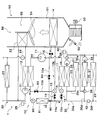
以下、実施形態について図に基づいて説明する。図1~2に示す車両用空調装置1は、車室内空間(換言すれば、空調対象空間)を適切な温度に調整する空調装置である。車両用空調装置1は、冷凍サイクル装置10を有している。本実施形態では、冷凍サイクル装置10を、エンジン(換言すれば内燃機関)および走行用モータ(換言すれば電動モータ)から車両走行用の駆動力を得るハイブリッド自動車に搭載されている。 First Embodiment
Hereinafter, embodiments will be described based on the drawings. Thevehicle air conditioner 1 shown in FIGS. 1 and 2 is an air conditioner that adjusts the vehicle interior space (in other words, the air conditioning target space) to an appropriate temperature. The vehicle air conditioner 1 has a refrigeration cycle apparatus 10. In the present embodiment, the refrigeration cycle apparatus 10 is mounted on a hybrid vehicle that obtains a driving force for vehicle traveling from an engine (in other words, an internal combustion engine) and a traveling motor (in other words, an electric motor).
以下、実施形態について図に基づいて説明する。図1~2に示す車両用空調装置1は、車室内空間(換言すれば、空調対象空間)を適切な温度に調整する空調装置である。車両用空調装置1は、冷凍サイクル装置10を有している。本実施形態では、冷凍サイクル装置10を、エンジン(換言すれば内燃機関)および走行用モータ(換言すれば電動モータ)から車両走行用の駆動力を得るハイブリッド自動車に搭載されている。 First Embodiment
Hereinafter, embodiments will be described based on the drawings. The
本実施形態のハイブリッド自動車は、車両停車時に外部電源(換言すれば商用電源)から供給された電力を、車両に搭載された電池(換言すれば車載バッテリ)に充電可能なプラグインハイブリッド自動車として構成されている。電池としては、例えばリチウムイオン電池を用いることができる。
The hybrid vehicle of the present embodiment is configured as a plug-in hybrid vehicle capable of charging a battery (in other words, an on-board battery) mounted on the vehicle with electric power supplied from an external power supply (in other words, a commercial power supply) It is done. For example, a lithium ion battery can be used as the battery.
充電モードとして、高電圧にて急速に充電する急速充電モードを有している。高電圧とは、家庭用電源の電圧よりも高い電圧のことであり、例えば、400Vや500V等の電圧である。
As a charge mode, it has a rapid charge mode which charges rapidly at high voltage. The high voltage is a voltage higher than the voltage of the home power source, and is, for example, a voltage such as 400 V or 500 V.
エンジンから出力される駆動力は、車両走行用として用いられるのみならず、発電機を作動させるためにも用いられる。そして、発電機にて発電された電力および外部電源から供給された電力を電池に蓄わえることができ、電池に蓄えられた電力は、走行用モータのみならず、冷凍サイクル装置10を構成する電動式構成機器をはじめとする各種車載機器に供給される。
The driving force output from the engine is used not only for driving the vehicle but also for operating the generator. The electric power generated by the generator and the electric power supplied from the external power supply can be stored in the battery, and the electric power stored in the battery constitutes the refrigeration cycle apparatus 10 as well as the driving motor. It is supplied to various in-vehicle devices including electric components.
冷凍サイクル装置10は、圧縮機11、凝縮器12、第1膨張弁80、室外熱交換器81、第2膨張弁13、空気冷却用蒸発器14、定圧弁15、第3膨張弁16および冷却水冷却用蒸発器17を備える蒸気圧縮式冷凍機である。本実施形態の冷凍サイクル装置10では、冷媒としてフロン系冷媒を用いており、高圧側冷媒圧力が冷媒の臨界圧力を超えない亜臨界冷凍サイクルを構成している。
The refrigeration cycle apparatus 10 includes a compressor 11, a condenser 12, a first expansion valve 80, an outdoor heat exchanger 81, a second expansion valve 13, an air cooling evaporator 14, a constant pressure valve 15, a third expansion valve 16, and cooling. This is a vapor compression type refrigerator equipped with a water cooling evaporator 17. In the refrigeration cycle apparatus 10 of this embodiment, a fluorocarbon-based refrigerant is used as the refrigerant, and a subcritical refrigeration cycle in which the high-pressure side refrigerant pressure does not exceed the critical pressure of the refrigerant is configured.
冷凍サイクル装置10は、直列冷媒流路10a、第1並列冷媒流路10b、第2並列冷媒流路10c、室外器バイパス流路10dおよび蒸発器バイパス流路10eを備える。直列冷媒流路10a、第1並列冷媒流路10b、第2並列冷媒流路10c、室外器バイパス流路10dおよび蒸発器バイパス流路10eは、冷媒が流れる流路である。
The refrigeration cycle apparatus 10 includes a series refrigerant flow path 10a, a first parallel refrigerant flow path 10b, a second parallel refrigerant flow path 10c, an outdoor unit bypass flow path 10d, and an evaporator bypass flow path 10e. The series refrigerant flow path 10a, the first parallel refrigerant flow path 10b, the second parallel refrigerant flow path 10c, the outdoor unit bypass flow path 10d and the evaporator bypass flow path 10e are flow paths through which the refrigerant flows.
直列冷媒流路10a、第1並列冷媒流路10bおよび第2並列冷媒流路10cによって、冷媒が循環する冷媒循環回路が形成されている。第1並列冷媒流路10bおよび第2並列冷媒流路10cは、冷媒が互いに並列に流れるように直列冷媒流路10aに接続されている。
A refrigerant circulation circuit in which the refrigerant circulates is formed by the series refrigerant flow passage 10a, the first parallel refrigerant flow passage 10b, and the second parallel refrigerant flow passage 10c. The first parallel refrigerant flow passage 10 b and the second parallel refrigerant flow passage 10 c are connected to the series refrigerant flow passage 10 a so that the refrigerant flows in parallel to each other.
直列冷媒流路10aには、圧縮機11、凝縮器12、第1膨張弁80および室外熱交換器81が、冷媒の流れにおいてこの順番で互いに直列に配置されている。
The compressor 11, the condenser 12, the first expansion valve 80, and the outdoor heat exchanger 81 are arranged in series in this order in the refrigerant flow in the series refrigerant flow path 10a.
第1並列冷媒流路10bには、第2膨張弁13、空気冷却用蒸発器14および定圧弁15が、冷媒の流れにおいてこの順番で互いに直列に配置されている。
In the first parallel refrigerant flow passage 10b, the second expansion valve 13, the air cooling evaporator 14 and the constant pressure valve 15 are arranged in series in this order in the flow of the refrigerant.
第2並列冷媒流路10cには、第3膨張弁16および冷却水冷却用蒸発器17が、冷媒の流れにおいてこの順番で互いに直列に配置されている。
In the second parallel refrigerant flow passage 10c, the third expansion valve 16 and the cooling water cooling evaporator 17 are arranged in series in this order in the flow of the refrigerant.
直列冷媒流路10aおよび第1並列冷媒流路10bによって、冷媒が圧縮機11、凝縮器12、第2膨張弁13、空気冷却用蒸発器14、定圧弁15、圧縮機11の順に循環する冷媒循環回路が形成される。
The refrigerant is circulated in the order of the compressor 11, the condenser 12, the second expansion valve 13, the air cooling evaporator 14, the constant pressure valve 15, and the compressor 11 by the series refrigerant flow path 10a and the first parallel refrigerant flow path 10b. A circulation circuit is formed.
直列冷媒流路10aおよび第2並列冷媒流路10cによって、冷媒が圧縮機11、凝縮器12、第3膨張弁16、冷却水冷却用蒸発器17の順に循環する冷媒循環回路が形成される。
A refrigerant circulation circuit in which the refrigerant circulates in the order of the compressor 11, the condenser 12, the third expansion valve 16, and the cooling water cooling evaporator 17 is formed by the series refrigerant flow passage 10a and the second parallel refrigerant flow passage 10c.
室外器バイパス流路10dは、凝縮器12から流出した冷媒が室外熱交換器81をバイパスして流れる流路である。蒸発器バイパス流路10eは、室外熱交換器81から流出した冷媒が空気冷却用蒸発器14をバイパスして流れる流路である。
The outdoor unit bypass flow passage 10 d is a flow passage through which the refrigerant flowing out of the condenser 12 bypasses the outdoor heat exchanger 81. The evaporator bypass flow passage 10 e is a flow passage through which the refrigerant flowing out of the outdoor heat exchanger 81 bypasses the air cooling evaporator 14.
室外器バイパス流路10dと直列冷媒流路10aとの合流部は、蒸発器バイパス流路10eと直列冷媒流路10aとの合流部よりも冷媒流れ下流側に位置している。
The junction of the outdoor bypass passage 10d and the series refrigerant passage 10a is located downstream of the junction of the evaporator bypass passage 10e and the series refrigerant passage 10a.
蒸発器バイパス流路10eと直列冷媒流路10aとの合流部と、室外器バイパス流路10dと直列冷媒流路10aとの合流部との間には、冷媒の逆流を防止する逆止弁82が配置されている。
A check valve 82 for preventing the backflow of the refrigerant between the junction of the evaporator bypass passage 10e and the series refrigerant passage 10a and the junction of the outdoor unit bypass passage 10d and the series refrigerant passage 10a. Is arranged.
室外器バイパス流路10dには室外機バイパス電磁弁83が配置されている。室外機バイパス電磁弁83は、室外器バイパス流路10dを開閉する。室外機バイパス電磁弁83の作動は、制御装置60によって制御される。
An outdoor unit bypass solenoid valve 83 is disposed in the outdoor unit bypass flow passage 10d. The outdoor unit bypass solenoid valve 83 opens and closes the outdoor unit bypass flow passage 10d. The operation of the outdoor unit bypass solenoid valve 83 is controlled by the control device 60.
凝縮器12から流出した冷媒が室外器バイパス流路10dを流れるように室外機バイパス電磁弁83を制御することによって、室外熱交換器81を流れる冷媒の流量を減少させて、室外熱交換器81における熱交換量を減少させることができる。
By controlling the outdoor unit bypass solenoid valve 83 such that the refrigerant flowing out of the condenser 12 flows through the outdoor unit bypass flow path 10d, the flow rate of the refrigerant flowing through the outdoor heat exchanger 81 is reduced, and the outdoor heat exchanger 81 The amount of heat exchange at can be reduced.
蒸発器バイパス流路10eには蒸発器バイパス電磁弁84が配置されている。蒸発器バイパス電磁弁84は、蒸発器バイパス流路10eを開閉する。蒸発器バイパス電磁弁84の作動は、制御装置60によって制御される。
An evaporator bypass solenoid valve 84 is disposed in the evaporator bypass flow passage 10 e. The evaporator bypass solenoid valve 84 opens and closes the evaporator bypass flow passage 10 e. The operation of the evaporator bypass solenoid valve 84 is controlled by the controller 60.
室外熱交換器81から流出した冷媒が蒸発器バイパス流路10eを流れるように蒸発器バイパス電磁弁84を制御することによって、空気冷却用蒸発器14を流れる冷媒の流量を減少させて、空気冷却用蒸発器14における熱交換量を減少させることができる。
By controlling the evaporator bypass solenoid valve 84 so that the refrigerant flowing out of the outdoor heat exchanger 81 flows through the evaporator bypass flow passage 10 e, the flow rate of the refrigerant flowing through the air cooling evaporator 14 is reduced to perform air cooling The amount of heat exchange in the evaporator 14 can be reduced.
圧縮機11は、電池から供給される電力によって駆動される電動圧縮機であり、冷凍サイクル装置10の冷媒を吸入して圧縮して吐出する。圧縮機11は、ベルトによって駆動される可変容量圧縮機であってもよい。
The compressor 11 is an electric compressor driven by electric power supplied from a battery, and sucks, compresses and discharges the refrigerant of the refrigeration cycle apparatus 10. The compressor 11 may be a variable displacement compressor driven by a belt.
凝縮器12は、圧縮機11から吐出された高圧側冷媒と高温冷却水回路20の冷却水とを熱交換させることによって高圧側冷媒を凝縮させる高圧側冷媒熱媒体熱交換器である。凝縮器12は、圧縮機11から吐出された高圧側冷媒と高温冷却水回路20の冷却水とを熱交換させることによって高温冷却水回路20の冷却水を加熱する熱媒体加熱熱交換器である。
The condenser 12 is a high pressure side refrigerant heat medium heat exchanger that condenses the high pressure side refrigerant by heat exchange between the high pressure side refrigerant discharged from the compressor 11 and the cooling water of the high temperature cooling water circuit 20. The condenser 12 is a heat medium heating heat exchanger that heats the cooling water of the high temperature cooling water circuit 20 by heat exchange between the high pressure side refrigerant discharged from the compressor 11 and the cooling water of the high temperature cooling water circuit 20. .
高温冷却水回路20の冷却水は、熱媒体としての流体である。高温冷却水回路20の冷却水は高温熱媒体である。本実施形態では、高温冷却水回路20の冷却水として、少なくともエチレングリコール、ジメチルポリシロキサンもしくはナノ流体を含む液体、または不凍液体が用いられている。高温冷却水回路20は、高温熱媒体が循環する高温熱媒体回路である。
The cooling water of the high temperature cooling water circuit 20 is a fluid as a heat medium. The cooling water of the high temperature cooling water circuit 20 is a high temperature heating medium. In the present embodiment, a liquid containing at least ethylene glycol, dimethylpolysiloxane or a nanofluid, or an antifreeze liquid is used as the cooling water of the high temperature cooling water circuit 20. The high temperature coolant circuit 20 is a high temperature heat medium circuit in which a high temperature heat medium circulates.
第1膨張弁80は、凝縮器12から流出した液相冷媒を減圧膨張させる第1減圧装置である。第1膨張弁80は、電気式の可変絞り機構であり、弁体と電動アクチュエータとを有している。弁体は、冷媒通路の通路開度(換言すれば絞り開度)を変更可能に構成されている。電動アクチュエータは、弁体の絞り開度を変化させるステッピングモータを有している。
The first expansion valve 80 is a first decompression device that decompresses and expands the liquid phase refrigerant flowing out of the condenser 12. The first expansion valve 80 is an electric variable throttle mechanism, and has a valve body and an electric actuator. The valve body is configured to be capable of changing the passage opening degree of the refrigerant passage (in other words, the throttle opening degree). The electric actuator has a stepping motor that changes the throttle opening of the valve body.
第1膨張弁80は、冷媒通路を全開する全開機能付きの可変絞り機構で構成されている。第1膨張弁80は、制御装置60から出力される制御信号によって、その作動が制御される。
The first expansion valve 80 is configured by a variable throttle mechanism with a fully open function that fully opens the refrigerant passage. The operation of the first expansion valve 80 is controlled by a control signal output from the controller 60.
室外熱交換器81は、第1膨張弁80で減圧膨張された冷媒と、外気とを熱交換させる冷媒外気熱交換器である。室外熱交換器81は、冷媒の有する熱を外気に放熱させる放熱部である。
The outdoor heat exchanger 81 is a refrigerant outside air heat exchanger that exchanges heat between the refrigerant decompressed and expanded by the first expansion valve 80 and the outside air. The outdoor heat exchanger 81 is a heat radiating portion that radiates the heat of the refrigerant to the outside air.
室外熱交換器81を流通する冷媒の温度が外気の温度よりも低い場合、室外熱交換器81は、外気の熱を冷媒に吸熱させる吸熱器として機能する。室外熱交換器81を流通する冷媒の温度が外気の温度よりも高い場合、室外熱交換器81は、冷媒の熱を外気に放熱させる放熱器として機能する。
When the temperature of the refrigerant flowing through the outdoor heat exchanger 81 is lower than the temperature of the outside air, the outdoor heat exchanger 81 functions as a heat absorber that absorbs the heat of the outside air by the refrigerant. When the temperature of the refrigerant flowing through the outdoor heat exchanger 81 is higher than the temperature of the outside air, the outdoor heat exchanger 81 functions as a radiator that radiates the heat of the refrigerant to the outside air.
第1膨張弁80は、暖房モードと冷房モードとを切り替えるモード切替部である。第1膨張弁80の絞り開度を制御することによって、室外熱交換器81が吸熱器として機能する状態と、室外熱交換器81が放熱器として機能する状態とを切り替えることができる。
The first expansion valve 80 is a mode switching unit that switches between the heating mode and the cooling mode. By controlling the opening degree of the first expansion valve 80, it is possible to switch between the state in which the outdoor heat exchanger 81 functions as a heat absorber and the state in which the outdoor heat exchanger 81 functions as a radiator.
室外熱交換器81を吸熱器として機能させることによって、外気の熱を暖房に利用できる。室外熱交換器81を放熱器として機能させることによって、冷凍サイクル装置10が生成した熱のうち余剰熱を外気に放熱させることができる。
By making the outdoor heat exchanger 81 function as a heat absorber, the heat of the outside air can be used for heating. By causing the outdoor heat exchanger 81 to function as a radiator, it is possible to dissipate excess heat among the heat generated by the refrigeration cycle apparatus 10 to the outside air.
第2膨張弁13は、室外熱交換器81から流出した液相冷媒を減圧膨張させる第2減圧装置である。第2膨張弁13は、機械式の温度式膨張弁である。機械式膨張弁は、感温部を有し、ダイヤフラム等の機械的機構によって弁体を駆動する温度式膨張弁である。
The second expansion valve 13 is a second decompression device that decompresses and expands the liquid phase refrigerant flowing out of the outdoor heat exchanger 81. The second expansion valve 13 is a mechanical temperature expansion valve. The mechanical expansion valve is a thermal expansion valve that has a temperature sensing unit and drives a valve body by a mechanical mechanism such as a diaphragm.
第1並列冷媒流路10bには、第1開閉弁18が配置されている。第1開閉弁18は、第1並列冷媒流路10bを開閉する電磁弁である。第1開閉弁18の作動は、制御装置60から出力される制御信号によって制御される。第1開閉弁18は、暖房モードと冷房モードとを切り替えるモード切替部である。
A first on-off valve 18 is disposed in the first parallel refrigerant flow passage 10b. The first on-off valve 18 is an electromagnetic valve that opens and closes the first parallel refrigerant flow passage 10 b. The operation of the first on-off valve 18 is controlled by a control signal output from the controller 60. The first on-off valve 18 is a mode switching unit that switches between the heating mode and the cooling mode.
第2膨張弁13は、冷媒通路を全閉する全閉機能付きの可変絞り機構で構成されている。つまり、第2膨張弁13は、冷媒通路を全閉にすることで冷媒の流れを遮断することができる。第2膨張弁13の作動は、図3に示す制御装置60から出力される制御信号によって制御される。
The second expansion valve 13 is configured by a variable throttle mechanism with a fully closing function that fully closes the refrigerant passage. That is, the second expansion valve 13 can shut off the flow of the refrigerant by fully closing the refrigerant passage. The operation of the second expansion valve 13 is controlled by a control signal output from a controller 60 shown in FIG.
空気冷却用蒸発器14は、第2膨張弁13から流出した冷媒と車室内へ送風される空気とを熱交換させて車室内へ送風される空気を冷却する空気冷却用熱交換器である。空気冷却用蒸発器14は、冷媒の有する冷熱を利用して空気を冷却する冷却部である。空気冷却用蒸発器14では、冷媒が車室内へ送風される空気から吸熱する。
The air-cooling evaporator 14 is an air-cooling heat exchanger that exchanges heat between the refrigerant flowing out of the second expansion valve 13 and the air blown into the vehicle compartment to cool the air blown into the vehicle compartment. The air cooling evaporator 14 is a cooling unit that cools air by using cold heat of a refrigerant. In the air cooling evaporator 14, the refrigerant absorbs heat from the air blown into the vehicle compartment.
定圧弁15は、空気冷却用蒸発器14の出口側における冷媒の圧力を所定値に維持する圧力調整部(換言すれば圧力調整用減圧部)である。
The constant pressure valve 15 is a pressure adjusting unit (in other words, a pressure adjusting pressure reducing unit) that maintains the pressure of the refrigerant at the outlet side of the air cooling evaporator 14 at a predetermined value.
定圧弁15は、機械式の可変絞り機構で構成されている。具体的には、定圧弁15は、空気冷却用蒸発器14の出口側における冷媒の圧力が所定値を下回ると冷媒通路の通路面積(すなわち絞り開度)を減少させ、空気冷却用蒸発器14の出口側における冷媒の圧力が所定値を超えると冷媒通路の通路面積(すなわち絞り開度)を増加させる。
The constant pressure valve 15 is configured by a mechanical variable throttle mechanism. Specifically, when the pressure of the refrigerant at the outlet side of the air cooling evaporator 14 falls below a predetermined value, the constant pressure valve 15 reduces the passage area (i.e., the throttle opening degree) of the refrigerant passage, and the air cooling evaporator 14 When the pressure of the refrigerant at the outlet side of the valve exceeds a predetermined value, the passage area (i.e., the throttle opening) of the refrigerant passage is increased.
サイクルを循環する循環冷媒流量の変動が少ない場合等には、定圧弁15に代えて、オリフィス、キャピラリチューブ等からなる固定絞りを採用してもよい。
In the case where the fluctuation of the flow rate of the circulating refrigerant circulating in the cycle is small, instead of the constant pressure valve 15, a fixed throttle consisting of an orifice, a capillary tube or the like may be adopted.
第3膨張弁16は、室外熱交換器81から流出した液相冷媒を減圧膨張させる第3減圧装置である。第3膨張弁16は、第2膨張弁13と同様に機械式の温度式膨張弁である。
The third expansion valve 16 is a third decompression device that decompresses and expands the liquid phase refrigerant flowing out of the outdoor heat exchanger 81. The third expansion valve 16 is, like the second expansion valve 13, a mechanical temperature expansion valve.
第2並列冷媒流路10cに第2開閉弁19が配置されている。第2開閉弁19は、第2並列冷媒流路10cを開閉する電磁弁である。第2開閉弁19の作動は、制御装置60から出力される制御信号によって制御される。
The second on-off valve 19 is disposed in the second parallel refrigerant flow passage 10c. The second on-off valve 19 is an electromagnetic valve that opens and closes the second parallel refrigerant flow passage 10c. The operation of the second on-off valve 19 is controlled by a control signal output from the controller 60.
冷却水冷却用蒸発器17は、第3膨張弁16を流出した低圧冷媒と低温冷却水回路30の冷却水とを熱交換させることによって低圧冷媒を蒸発させる低圧側冷媒熱媒体熱交換器である。冷却水冷却用蒸発器17は、冷媒と低温冷却水回路30の冷却水を熱交換させて低温冷却水回路30の冷却水を冷却する熱媒体冷却熱交換器である。冷却水冷却用蒸発器17で蒸発した気相冷媒は圧縮機11に吸入されて圧縮される。
The cooling water cooling evaporator 17 is a low pressure side refrigerant heat medium heat exchanger that evaporates the low pressure refrigerant by heat exchange between the low pressure refrigerant flowing out of the third expansion valve 16 and the cooling water of the low temperature cooling water circuit 30. . The cooling water cooling evaporator 17 is a heat medium cooling heat exchanger which exchanges heat between the refrigerant and the low temperature cooling water circuit 30 to cool the cooling water of the low temperature cooling water circuit 30. The gas phase refrigerant evaporated in the cooling water cooling evaporator 17 is drawn into the compressor 11 and compressed.
低温冷却水回路30の冷却水は、熱媒体としての流体である。低温冷却水回路30の冷却水は低温熱媒体である。本実施形態では、低温冷却水回路30の冷却水として、少なくともエチレングリコール、ジメチルポリシロキサンもしくはナノ流体を含む液体、または不凍液体が用いられている。低温冷却水回路30は、低温熱媒体が循環する低温熱媒体回路である。
The cooling water of the low temperature cooling water circuit 30 is a fluid as a heat medium. The cooling water of the low temperature cooling water circuit 30 is a low temperature heating medium. In the present embodiment, a liquid containing at least ethylene glycol, dimethylpolysiloxane or nanofluid, or an antifreeze liquid is used as the cooling water of the low temperature cooling water circuit 30. The low temperature coolant circuit 30 is a low temperature heat medium circuit in which a low temperature heat medium circulates.
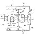
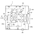
高温冷却水回路20には、凝縮器12、高温側ポンプ21、ヒータコア22、ラジエータ23、二方弁24および高温側リザーブタンク25が配置されている。
In the high temperature coolant circuit 20, a condenser 12, a high temperature side pump 21, a heater core 22, a radiator 23, a two-way valve 24, and a high temperature side reserve tank 25 are disposed.
高温側ポンプ21は、冷却水を吸入して吐出する熱媒体ポンプである。高温側ポンプ21は電動式のポンプである。
The high temperature side pump 21 is a heat medium pump that sucks in and discharges the cooling water. The high temperature side pump 21 is an electric pump.
高温側ポンプ21は、高温冷却水回路20を循環する冷却水の流量を調整する高温側流量調整部である。第1低温側ポンプ31および第2低温側ポンプ34は、低温冷却水回路30を循環する冷却水の流量を調整する低温側流量調整部である。
The high temperature side pump 21 is a high temperature side flow rate adjustment unit that adjusts the flow rate of the cooling water circulating in the high temperature cooling water circuit 20. The first low temperature side pump 31 and the second low temperature side pump 34 are low temperature side flow rate adjustment units that adjust the flow rate of the cooling water circulating in the low temperature cooling water circuit 30.
ヒータコア22は、高温冷却水回路20の冷却水と車室内へ送風される空気とを熱交換させて車室内へ送風される空気を加熱する空気加熱用熱交換器である。ヒータコア22は、高温冷却水回路20の冷却水と車室内へ送風される空気とを熱交換させて空気を加熱する空気加熱熱交換器である。
The heater core 22 is an air heating heat exchanger that heat-exchanges the cooling water of the high-temperature coolant circuit 20 with the air blown into the vehicle compartment to heat the air blown into the vehicle compartment. The heater core 22 is an air heating heat exchanger that heats the air by heat exchange between the cooling water of the high temperature coolant circuit 20 and the air blown into the vehicle compartment.
凝縮器12およびヒータコア22は、圧縮機11から吐出された冷媒の有する熱を熱源として、空調対象空間へ送風される空気を加熱する加熱部である。
The condenser 12 and the heater core 22 are heating units that use the heat of the refrigerant discharged from the compressor 11 as a heat source to heat the air blown into the space to be air conditioned.
ラジエータ23は、高温冷却水回路20の冷却水と外気とを熱交換させる高温熱媒体外気熱交換器である。凝縮器12およびラジエータ23は、冷媒の有する熱を外気に放熱させる放熱部である。
The radiator 23 is a high-temperature heat medium external air heat exchanger that exchanges heat between the cooling water of the high-temperature cooling water circuit 20 and the outside air. The condenser 12 and the radiator 23 are heat radiating parts that radiate the heat of the refrigerant to the outside air.
ラジエータ23は、高温冷却水回路20および低温冷却水回路30の両方に共通のラジエータである。ラジエータ23および室外熱交換器81には、室外送風機41によって外気が送風される。
The radiator 23 is a radiator common to both the high temperature coolant circuit 20 and the low temperature coolant circuit 30. Outside air is blown to the radiator 23 and the outdoor heat exchanger 81 by the outdoor blower 41.
ラジエータ23は、高温冷却水回路20および低温冷却水回路30の両方に共通のラジエータである。ラジエータ23および室外熱交換器81には、図2に示す室外送風機41によって外気が送風される。
The radiator 23 is a radiator common to both the high temperature coolant circuit 20 and the low temperature coolant circuit 30. Outside air is blown to the radiator 23 and the outdoor heat exchanger 81 by the outdoor blower 41 shown in FIG.
室外送風機41は、ラジエータ23および室外熱交換器81へ向けて外気を送風する外気送風部である。室外送風機41は、ファンを電動モータにて駆動する電動送風機である。ラジエータ23、室外熱交換器81および室外送風機41は、車両の最前部に配置されている。従って、車両の走行時にはラジエータ23および室外熱交換器81に走行風を当てることができるようになっている。
The outdoor blower 41 is an outside air blower that blows outside air toward the radiator 23 and the outdoor heat exchanger 81. The outdoor blower 41 is an electric blower which drives a fan by an electric motor. The radiator 23, the outdoor heat exchanger 81, and the outdoor blower 41 are disposed at the foremost part of the vehicle. Therefore, the traveling wind can be applied to the radiator 23 and the outdoor heat exchanger 81 when the vehicle travels.
凝縮器12、高温側ポンプ21およびヒータコア22は、高温側循環流路20aに配置されている。高温側循環流路20aは、高温側冷却水が循環する流路である。
The condenser 12, the high temperature side pump 21 and the heater core 22 are disposed in the high temperature side circulation flow passage 20a. The high temperature side circulation flow passage 20a is a flow passage through which the high temperature side cooling water circulates.
ラジエータ23および二方弁24は、ラジエータ流路20bに配置されている。ラジエータ流路20bは、高温側冷却水がヒータコア22に対して並列に流れる流路である。
The radiator 23 and the two-way valve 24 are disposed in the radiator flow passage 20b. The radiator flow passage 20 b is a flow passage through which the high temperature side cooling water flows in parallel to the heater core 22.
ラジエータ流路20bの一部は、低温冷却水回路30の一部を構成している。すなわち、ラジエータ流路20bの一部は、高温冷却水回路20および低温冷却水回路30の両方に共通の冷却水流路である。
A part of the radiator flow passage 20 b constitutes a part of the low temperature coolant circuit 30. That is, a part of the radiator flow passage 20 b is a cooling water flow passage common to both the high temperature cooling water circuit 20 and the low temperature cooling water circuit 30.
二方弁24は、ラジエータ流路20bを開閉する電磁弁である。二方弁24の作動は、制御装置60によって制御される。二方弁24は、高温冷却水回路20における冷却水の流れを切り替える高温切替部である。
The two-way valve 24 is a solenoid valve that opens and closes the radiator flow passage 20b. The operation of the two-way valve 24 is controlled by the controller 60. The two-way valve 24 is a high temperature switching unit that switches the flow of the cooling water in the high temperature cooling water circuit 20.
二方弁24は、サーモスタットであってもよい。サーモスタットは、温度によって体積変化するサーモワックスによって弁体を変位させて冷却水流路を開閉する機械的機構を備える冷却水温度応動弁である。
The two-way valve 24 may be a thermostat. The thermostat is a cooling water temperature responsive valve provided with a mechanical mechanism that opens and closes the cooling water flow path by displacing the valve body by a thermowax that changes its volume depending on temperature.
高温側リザーブタンク25は、余剰冷却水を貯留する冷却水貯留部である。高温側リザーブタンク25に余剰冷却水を貯留しておくことによって、各流路を循環する冷却水の液量の低下を抑制することができる。
The high temperature side reserve tank 25 is a cooling water storage unit that stores excess cooling water. By storing the excess cooling water in the high temperature side reserve tank 25, it is possible to suppress a decrease in the amount of cooling water circulating in each flow path.
高温側リザーブタンク25は、密閉式リザーブタンクや大気開放式リザーブタンクである。密閉式リザーブタンクは、蓄えている冷却水の液面における圧力が所定圧力になるようなリザーブタンクである。大気開放式リザーブタンクは、蓄えている冷却水の液面における圧力が大気圧になるようなリザーブタンクである。
The high temperature side reserve tank 25 is a closed reserve tank or an open air reserve tank. The closed reserve tank is a reserve tank in which the pressure at the liquid surface of the stored cooling water is a predetermined pressure. The open air type reserve tank is a reserve tank in which the pressure at the liquid surface of the stored cooling water is atmospheric pressure.
低温冷却水回路30には、冷却水冷却用蒸発器17、第1低温側ポンプ31、ラジエータ23、電池33、第2低温側ポンプ34、インバータ35、チャージャ36、モータジェネレータ37、第1三方弁38、第2三方弁39および低温側リザーブタンク40が配置されている。
In the low temperature cooling water circuit 30, a cooling water cooling evaporator 17, a first low temperature side pump 31, a radiator 23, a battery 33, a second low temperature side pump 34, an inverter 35, a charger 36, a motor generator 37, a first three-way valve 38, a second three-way valve 39 and a low temperature side reserve tank 40 are disposed.
第1低温側ポンプ31および第2低温側ポンプ34は、冷却水を吸入して吐出する熱媒体ポンプである。第1低温側ポンプ31および第2低温側ポンプ34は電動式のポンプである。
The first low temperature side pump 31 and the second low temperature side pump 34 are heat medium pumps that suck and discharge the cooling water. The first low temperature side pump 31 and the second low temperature side pump 34 are electric pumps.
図1、図2に示す電池33、インバータ35、チャージャ36およびモータジェネレータ37は、車両に搭載された車載機器であり、作動に伴って発熱する発熱機器である。電池33およびチャージャ36は、電池33の充電に伴って発熱する充電系発熱機器である。インバータ35およびモータジェネレータ37は、電池33から電力の供給を受けることに伴って発熱する走行系発熱機器である。
The battery 33, the inverter 35, the charger 36, and the motor generator 37 shown in FIGS. 1 and 2 are in-vehicle devices mounted in a vehicle, and are heat generating devices that generate heat as they operate. The battery 33 and the charger 36 are charging system heat generating devices that generate heat as the battery 33 is charged. Inverter 35 and motor generator 37 are traveling system heat generating devices that generate heat in response to the supply of power from battery 33.
電池33、インバータ35、チャージャ36およびモータジェネレータ37は、作動に伴って発生する廃熱を低温冷却水回路30の冷却水に放熱する。換言すれば、電池33、インバータ35、チャージャ36およびモータジェネレータ37は、低温冷却水回路30の冷却水に熱を供給する。
The battery 33, the inverter 35, the charger 36 and the motor generator 37 dissipate the waste heat generated as the operation is performed to the cooling water of the low temperature cooling water circuit 30. In other words, the battery 33, the inverter 35, the charger 36 and the motor generator 37 supply heat to the cooling water of the low temperature cooling water circuit 30.
インバータ35は、電池33から供給された直流電力を交流電力に変換してモータジェネレータ37に出力する電力変換部である。チャージャ36は、電池33を充電するための充電器である。モータジェネレータ37は、インバータ35から出力された電力を利用して走行用駆動力を発生するとともに、減速中や降坂中に回生電力を発生させる。
The inverter 35 is a power conversion unit that converts DC power supplied from the battery 33 into AC power and outputs the AC power to the motor generator 37. The charger 36 is a charger for charging the battery 33. The motor generator 37 generates driving power for traveling using the electric power output from the inverter 35, and generates regenerative electric power during deceleration or downhill.
例えば、電池33の上限温度は50℃程度である。インバータ35およびモータジェネレータ37の上限温度は、電池33の上限温度よりも高くなっており、例えば65℃程度である。チャージャ36の上限温度は、インバータ35およびモータジェネレータ37の上限温度よりも高くなっている。電池33、インバータ35、チャージャ36およびモータジェネレータ37は、劣化や故障の防止のために、上限温度(換言すれば保護温度)以下の温度に保たれる必要がある。
For example, the upper limit temperature of the battery 33 is about 50.degree. The upper limit temperature of the inverter 35 and the motor generator 37 is higher than the upper limit temperature of the battery 33, and is about 65 ° C., for example. The upper limit temperature of charger 36 is higher than the upper limit temperatures of inverter 35 and motor generator 37. The battery 33, the inverter 35, the charger 36 and the motor generator 37 need to be maintained at a temperature lower than the upper limit temperature (in other words, the protection temperature) in order to prevent deterioration or failure.
低温側リザーブタンク40は、余剰冷却水を貯留する冷却水貯留部である。低温側リザーブタンク40に余剰冷却水を貯留しておくことによって、各流路を循環する冷却水の液量の低下を抑制することができる。
The low temperature side reserve tank 40 is a cooling water storage unit that stores excess cooling water. By storing the excess cooling water in the low temperature side reserve tank 40, it is possible to suppress a decrease in the amount of cooling water circulating in each flow path.
低温側リザーブタンク40は、密閉式リザーブタンクや大気開放式リザーブタンクである。密閉式リザーブタンクは、蓄えている冷却水の液面における圧力が所定圧力になるようなリザーブタンクである。大気開放式リザーブタンクは、蓄えている冷却水の液面における圧力が大気圧になるようなリザーブタンクである。
The low temperature side reserve tank 40 is a closed reserve tank or an open air reserve tank. The closed reserve tank is a reserve tank in which the pressure at the liquid surface of the stored cooling water is a predetermined pressure. The open air type reserve tank is a reserve tank in which the pressure at the liquid surface of the stored cooling water is atmospheric pressure.
第1三方弁38、第1低温側ポンプ31、冷却水冷却用蒸発器17および低温側リザーブタンク40は、低温側主流路30aに配置されている。低温側主流路30aは、低温側冷却水が流れる流路である。
The first three-way valve 38, the first low temperature side pump 31, the cooling water cooling evaporator 17, and the low temperature side reserve tank 40 are disposed in the low temperature side main flow passage 30a. The low temperature side main flow passage 30a is a flow passage through which the low temperature side cooling water flows.
電池33およびチャージャ36は、電池流路30cに配置されている。電池流路30cは、低温側主流路30aに接続されている。低温側主流路30aおよび電池流路30cによって、低温側冷却水が循環する冷却水回路が形成される。
The battery 33 and the charger 36 are disposed in the battery flow passage 30c. The battery flow passage 30c is connected to the low temperature side main flow passage 30a. The low temperature side main flow passage 30a and the battery flow passage 30c form a cooling water circuit in which the low temperature side cooling water is circulated.
低温側主流路30aと電池流路30cとの接続部には、第1三方弁38が配置されている。第1三方弁38は、低温側主流路30aの冷却水が電池流路30cに循環する状態と循環しない状態とを切り替える。第1三方弁38の作動は、制御装置60によって制御される。
A first three-way valve 38 is disposed at the connection between the low temperature side main flow passage 30a and the battery flow passage 30c. The first three-way valve 38 switches between a state in which the cooling water in the low temperature side main flow path 30 a circulates in the battery flow path 30 c and a state in which the cooling water does not circulate. The operation of the first three-way valve 38 is controlled by the controller 60.
第2低温側ポンプ34、インバータ35およびモータジェネレータ37は、機器流路30dに配置されている。低温側主流路30aおよび機器流路30dによって、低温側冷却水が循環する冷却水回路が形成される。
The second low temperature side pump 34, the inverter 35 and the motor generator 37 are disposed in the device flow path 30d. The low temperature side main flow passage 30a and the device flow passage 30d form a cooling water circuit in which the low temperature side cooling water circulates.
機器流路30dには、バイパス流路30eが接続されている。機器流路30dおよびバイパス流路30eによって、低温側冷却水が循環する冷却水回路が形成される。
A bypass flow passage 30e is connected to the device flow passage 30d. The device flow path 30 d and the bypass flow path 30 e form a cooling water circuit in which the low temperature side cooling water circulates.
機器流路30dとバイパス流路30eとの接続部には、第2三方弁39が配置されている。第2三方弁39は、低温側主流路30aの冷却水が機器流路30dに循環する状態と循環しない状態とを切り替えるとともに、機器流路30dの冷却水がバイパス流路30eに循環する状態と循環しない状態とを切り替える。第2三方弁39の作動は、制御装置60によって制御される。
A second three-way valve 39 is disposed at the connection between the device flow path 30d and the bypass flow path 30e. The second three-way valve 39 switches between a state in which the cooling water in the low temperature side main flow passage 30a circulates in the device flow passage 30d and a state in which the cooling water in the device flow passage 30d circulates in the bypass flow passage 30e. Switch between non-circulating state. The operation of the second three-way valve 39 is controlled by the controller 60.
第1三方弁38および第2三方弁39は、低温冷却水回路30における冷却水の流れを切り替える低温切替部である。
The first three-way valve 38 and the second three-way valve 39 are low temperature switching units that switch the flow of the cooling water in the low temperature cooling water circuit 30.
ラジエータ接続流路30f、30gは、低温側主流路30aとラジエータ流路20bとを接続する冷却水流路である。低温側主流路30a、ラジエータ接続流路30f、30gおよびラジエータ流路20bによって、低温側冷却水が循環する冷却水回路が形成される。
The radiator connection channels 30f, 30g are cooling water channels connecting the low temperature side main channel 30a and the radiator channel 20b. The low temperature side main flow passage 30a, the radiator connection flow passages 30f and 30g, and the radiator flow passage 20b form a cooling water circuit in which the low temperature side cooling water circulates.
ラジエータ接続流路30fには、ラジエータ二方弁42が配置されている。ラジエータ二方弁42は、ラジエータ接続流路30fを開閉する。ラジエータ二方弁42の作動は、制御装置60によって制御される。ラジエータ二方弁42は、低温冷却水回路30における冷却水の流れを切り替える低温切替部である。ラジエータ二方弁42は、サーモスタットであってもよい。
A radiator two-way valve 42 is disposed in the radiator connection flow passage 30 f. The radiator two-way valve 42 opens and closes the radiator connection flow passage 30 f. The operation of the radiator two-way valve 42 is controlled by the controller 60. The radiator two-way valve 42 is a low temperature switching unit that switches the flow of the cooling water in the low temperature cooling water circuit 30. The radiator two-way valve 42 may be a thermostat.
空気冷却用蒸発器14およびヒータコア22は、図1に示す室内空調ユニット50のケーシング51(以下、空調ケーシングと言う。)に収容されている。室内空調ユニット50は、車室内前部の図示しない計器盤の内側に配置されている。空調ケーシング51は、空気通路を形成する空気通路形成部材である。
The air cooling evaporator 14 and the heater core 22 are housed in a casing 51 (hereinafter referred to as an air conditioning casing) of the indoor air conditioning unit 50 shown in FIG. 1. The indoor air conditioning unit 50 is disposed inside the instrument panel (not shown) at the front of the passenger compartment. The air conditioning casing 51 is an air passage forming member that forms an air passage.
ヒータコア22は、空調ケーシング51内の空気通路において、空気冷却用蒸発器14の空気流れ下流側に配置されている。空調ケーシング51には、内外気切替箱52と室内送風機53とが配置されている。内外気切替箱52は、空調ケーシング51内の空気通路に内気と外気とを切替導入する内外気切替部である。室内送風機53は、内外気切替箱52を通して空調ケーシング51内の空気通路に導入された内気および外気を吸入して送風する。
The heater core 22 is disposed on the air flow downstream side of the air cooling evaporator 14 in the air passage in the air conditioning casing 51. In the air conditioning casing 51, an inside / outside air switching box 52 and an indoor blower 53 are disposed. The inside / outside air switching box 52 is an inside / outside air switching unit that switches and introduces inside air and outside air to the air passage in the air conditioning casing 51. The indoor blower 53 sucks and blows the inside air and the outside air introduced into the air passage in the air conditioning casing 51 through the inside / outside air switching box 52.
空調ケーシング51内の空気通路において空気冷却用蒸発器14とヒータコア22との間には、エアミックスドア54が配置されている。エアミックスドア54は、空気冷却用蒸発器14を通過した冷風のうちヒータコア22に流入する冷風と冷風バイパス通路55を流れる冷風との風量割合を調整する。エアミックスドア54は、ヒータコア22における空気の加熱量を調整する空気加熱量調整部である。エアミックスドア54は、暖房モードと冷房モードとを切り替えるモード切替部である。
An air mix door 54 is disposed between the air cooling evaporator 14 and the heater core 22 in the air passage in the air conditioning casing 51. The air mix door 54 adjusts the volume ratio of the cold air flowing into the heater core 22 and the cold air flowing through the cold air bypass passage 55 among the cold air having passed through the air cooling evaporator 14. The air mix door 54 is an air heating amount adjustment unit that adjusts the heating amount of air in the heater core 22. The air mix door 54 is a mode switching unit that switches between the heating mode and the cooling mode.
冷風バイパス通路55は、空気冷却用蒸発器14を通過した冷風がヒータコア22をバイスして流れる空気通路である。
The cold air bypass passage 55 is an air passage through which the cold air that has passed through the air cooling evaporator 14 flows to bypass the heater core 22.
エアミックスドア54は、空調ケーシング51に対して回転可能に支持された回転軸と、回転軸に結合されたドア基板部とを有する回転式ドアである。エアミックスドア54の開度位置を調整することによって、空調ケーシング51から車室内に吹き出される空調風の温度を所望温度に調整できる。
The air mix door 54 is a rotary door having a rotary shaft rotatably supported on the air conditioning casing 51 and a door base portion coupled to the rotary shaft. By adjusting the position of the air mix door 54, the temperature of the conditioned air blown out from the air conditioning casing 51 into the vehicle compartment can be adjusted to a desired temperature.
エアミックスドア54の回転軸は、サーボモータによって駆動される。サーボモータの作動は、制御装置60によって制御される。
The rotation shaft of the air mix door 54 is driven by a servomotor. The operation of the servomotor is controlled by the controller 60.
エアミックスドア54は、空気流れと略直交する方向にスライド移動するスライドドアであってもよい。スライドドアは、剛体で形成された板状のドアであってもよいし。可撓性を有するフィルム材で形成されたフィルムドアであってもよい。
The air mix door 54 may be a slide door that slides in a direction substantially orthogonal to the air flow. The sliding door may be a plate-like door formed of a rigid body. It may be a film door formed of a flexible film material.
エアミックスドア54によって温度調整された空調風は、空調ケーシング51に形成された吹出口56から車室内へ吹き出される。
The conditioned air whose temperature has been adjusted by the air mix door 54 is blown out from the air outlet 56 formed in the air conditioning casing 51 into the vehicle compartment.
図3に示す制御装置60は、CPU、ROMおよびRAM等を含む周知のマイクロコンピュータとその周辺回路から構成されている。制御装置60は、ROM内に記憶された制御プログラムに基づいて各種演算、処理を行う。制御装置60の出力側には各種制御対象機器が接続されている。制御装置60は、各種制御対象機器の作動を制御する制御部である。
The control device 60 shown in FIG. 3 is composed of a known microcomputer including a CPU, a ROM, a RAM and the like, and peripheral circuits thereof. The control device 60 performs various operations and processing based on the control program stored in the ROM. Various control target devices are connected to the output side of the control device 60. The control device 60 is a control unit that controls the operation of various control target devices.
制御装置60によって制御される制御対象機器は、圧縮機11、第1膨張弁80、第2膨張弁13、第3膨張弁16、室外送風機41、高温側ポンプ21、二方弁24、第1低温側ポンプ31、第2低温側ポンプ34、第1三方弁38、第2三方弁39およびラジエータ二方弁42等である。
The control target devices controlled by the control device 60 include the compressor 11, the first expansion valve 80, the second expansion valve 13, the third expansion valve 16, the outdoor blower 41, the high temperature side pump 21, the two-way valve 24, the first The low-temperature side pump 31, the second low-temperature side pump 34, the first three-way valve 38, the second three-way valve 39, the radiator two-way valve 42, and the like.
制御装置60のうち圧縮機11の電動モータを制御するソフトウェアおよびハードウェアは、冷媒吐出能力制御部である。制御装置60のうち第1膨張弁80、第2膨張弁13および第3膨張弁16を制御するソフトウェアおよびハードウェアは、絞り制御部である。
The software and hardware for controlling the electric motor of the compressor 11 in the control device 60 are a refrigerant discharge capacity control unit. Software and hardware for controlling the first expansion valve 80, the second expansion valve 13, and the third expansion valve 16 in the control device 60 is a throttle control unit.
制御装置60のうち高温側ポンプ21を制御するソフトウェアおよびハードウェアは、高温熱媒体流量制御部である。制御装置60のうち第1低温側ポンプ31および第2低温側ポンプ34を制御するソフトウェアおよびハードウェアは、低温熱媒体流量制御部である。
Software and hardware for controlling the high temperature side pump 21 in the control device 60 is a high temperature heat medium flow rate control unit. The software and hardware for controlling the first low temperature side pump 31 and the second low temperature side pump 34 in the control device 60 is a low temperature heat medium flow rate control unit.
制御装置60のうち室外送風機41を制御するソフトウェアおよびハードウェアは、外気送風能力制御部である。制御装置60のうち二方弁24を制御するソフトウェアおよびハードウェアは、二方弁制御部である。
Software and hardware for controlling the outdoor blower 41 in the control device 60 are an outdoor air blowing capacity control unit. The software and hardware for controlling the two-way valve 24 in the controller 60 is a two-way valve control unit.
制御装置60のうち第1三方弁38を制御するソフトウェアおよびハードウェアは、第1三方弁制御部である。制御装置60のうち第2三方弁39を制御するソフトウェアおよびハードウェアは、第2三方弁制御部である。
The software and hardware for controlling the first three-way valve 38 in the controller 60 is a first three-way valve control unit. Software and hardware for controlling the second three-way valve 39 in the controller 60 is a second three-way valve control unit.
制御装置60の入力側には、内気温度センサ61、外気温度センサ62、日射量センサ63、蒸発器温度センサ64、ヒータコア温度センサ65、冷媒圧力センサ66、高温冷却水温度センサ67、低温冷却水温度センサ68、窓表面湿度センサ69等の種々の制御用センサ群が接続されている。
An inside air temperature sensor 61, an outside air temperature sensor 62, a solar radiation amount sensor 63, an evaporator temperature sensor 64, a heater core temperature sensor 65, a refrigerant pressure sensor 66, a high temperature coolant temperature sensor 67, and a low temperature coolant Various control sensor groups such as a temperature sensor 68 and a window surface humidity sensor 69 are connected.
内気温度センサ61は車室内温度Trを検出する。外気温度センサ62は外気温Tamを検出する。日射量センサ63は車室内の日射量Tsを検出する。
The inside air temperature sensor 61 detects a temperature Tr in the passenger compartment. The outside air temperature sensor 62 detects the outside air temperature Tam. The solar radiation amount sensor 63 detects the solar radiation amount Ts in the vehicle compartment.
蒸発器温度センサ64は、空気冷却用蒸発器14の温度を検出する温度検出部である。蒸発器温度センサ64は、例えば、空気冷却用蒸発器14の熱交換フィンの温度を検出するフィンサーミスタや、空気冷却用蒸発器14を流れる冷媒の温度を検出する冷媒温度センサ等である。
The evaporator temperature sensor 64 is a temperature detection unit that detects the temperature of the air cooling evaporator 14. The evaporator temperature sensor 64 is, for example, a fin thermistor that detects the temperature of heat exchange fins of the air cooling evaporator 14 or a refrigerant temperature sensor that detects the temperature of the refrigerant flowing through the air cooling evaporator 14.
ヒータコア温度センサ65は、ヒータコア22の温度を検出する温度検出部である。ヒータコア温度センサ65は、例えば、ヒータコア22の熱交換フィンの温度を検出するフィンサーミスタや、ヒータコア22を流れる冷却水の温度を検出する冷媒温度センサ、ヒータコア22から流出した空気の温度を検出する空気温度センサ等である。
The heater core temperature sensor 65 is a temperature detection unit that detects the temperature of the heater core 22. The heater core temperature sensor 65 is, for example, a fin thermistor that detects the temperature of heat exchange fins of the heater core 22, a refrigerant temperature sensor that detects the temperature of cooling water flowing through the heater core 22, and air that detects the temperature of air flowing out of the heater core 22. It is a temperature sensor or the like.
冷媒圧力センサ66は、圧縮機11から吐出された冷媒の圧力を検出する冷媒圧力検出部である。冷媒圧力センサ66の代わりに冷媒温度センサが制御装置60の入力側に接続されていてもよい。冷媒温度センサは、圧縮機11から吐出された冷媒の温度を検出する冷媒圧力検出部である。制御装置60は、冷媒の温度に基づいて冷媒の圧力を推定してもよい。
The refrigerant pressure sensor 66 is a refrigerant pressure detection unit that detects the pressure of the refrigerant discharged from the compressor 11. Instead of the refrigerant pressure sensor 66, a refrigerant temperature sensor may be connected to the input side of the control device 60. The refrigerant temperature sensor is a refrigerant pressure detection unit that detects the temperature of the refrigerant discharged from the compressor 11. The controller 60 may estimate the pressure of the refrigerant based on the temperature of the refrigerant.
高温冷却水温度センサ67は、高温冷却水回路20の冷却水の温度を検出する温度検出部である。例えば、高温冷却水温度センサ67は、凝縮器12の冷却水の温度を検出する。
The high temperature coolant temperature sensor 67 is a temperature detection unit that detects the temperature of the coolant in the high temperature coolant circuit 20. For example, the high temperature coolant temperature sensor 67 detects the temperature of the coolant of the condenser 12.
低温冷却水温度センサ68は、低温冷却水回路30の冷却水の温度を検出する温度検出部である。例えば、低温冷却水温度センサ68は、冷却水冷却用蒸発器17の冷却水の温度を検出する。
The low temperature coolant temperature sensor 68 is a temperature detection unit that detects the temperature of the coolant in the low temperature coolant circuit 30. For example, the low temperature coolant temperature sensor 68 detects the temperature of the coolant of the coolant cooling evaporator 17.
窓表面湿度センサ69は、窓近傍湿度センサ、窓近傍空気温度センサおよび窓表面温度センサで構成されている。
The window surface humidity sensor 69 is configured of a near window humidity sensor, a near window air temperature sensor, and a window surface temperature sensor.
窓近傍湿度センサは、車室内のフロントガラス近傍の車室内空気の相対湿度(以下、窓近傍相対湿度と言う。)を検出する。窓近傍空気温度センサは、フロントガラス近傍の車室内空気の温度を検出する。窓表面温度センサは、フロントガラスの表面温度を検出する。
The near-window humidity sensor detects the relative humidity (hereinafter referred to as the near-window relative humidity) of the air in the vehicle room near the windshield in the vehicle room. The near-window air temperature sensor detects the temperature of the air in the passenger compartment near the windshield. The window surface temperature sensor detects the surface temperature of the windshield.
制御装置60の入力側には、図示しない各種操作スイッチが接続されている。各種操作スイッチは操作パネル70に設けられており、乗員によって操作される。操作パネル70は車室内前部の計器盤付近に配置されている。制御装置60には、各種操作スイッチからの操作信号が入力される。
Various operation switches (not shown) are connected to the input side of the control device 60. Various operation switches are provided on the operation panel 70 and operated by the occupant. The operation panel 70 is disposed near the dashboard in the front of the vehicle compartment. Operation signals from various operation switches are input to the control device 60.
各種操作スイッチは、エアコンスイッチ、温度設定スイッチ等である。エアコンスイッチは、室内空調ユニット50にて空気の冷却を行うか否かを設定する。温度設定スイッチは、車室内の設定温度を設定する。
The various operation switches are an air conditioner switch, a temperature setting switch, and the like. The air conditioner switch sets whether to cool the air in the indoor air conditioning unit 50 or not. The temperature setting switch sets the set temperature of the vehicle interior.
次に、上記構成における作動を説明する。制御装置60は、目標吹出温度TAO等に基づいて運転モードを、図4~5に示す冷房モードおよび図6~7に示す暖房モードのいずれかに切り替える。冷房モードは、車室内へ送風される空気を冷却する空気冷却モードである。暖房モードは、車室内へ送風される空気を加熱する空気加熱モードである。
Next, the operation in the above configuration will be described. The control device 60 switches the operation mode to one of the cooling mode shown in FIGS. 4 to 5 and the heating mode shown in FIGS. 6 to 7 based on the target blowing temperature TAO or the like. The cooling mode is an air cooling mode for cooling the air blown into the vehicle compartment. The heating mode is an air heating mode in which the air blown into the vehicle compartment is heated.
目標吹出温度TAOは、車室内へ吹き出す吹出空気の目標温度である。制御装置60は、目標吹出温度TAOを以下の数式に基づいて算出する。
The target blowing temperature TAO is a target temperature of the blowing air blown out into the vehicle compartment. Control device 60 calculates target blowout temperature TAO based on the following formula.
TAO=Kset×Tset-Kr×Tr-Kam×Tam-Ks×Ts+C
この数式において、Tsetは操作パネル70の温度設定スイッチによって設定された車室内設定温度、Trは内気温度センサ61によって検出された内気温、Tamは外気温度センサ62によって検出された外気温、Tsは日射量センサ63によって検出された日射量である。Kset、Kr、Kam、Ksは制御ゲインであり、Cは補正用の定数である。 TAO = Kset × Tset-Kr × Tr-Kam × Tam-Ks × Ts + C
In this equation, Tset is a vehicle interior set temperature set by the temperature setting switch of theoperation panel 70, Tr is the inside air temperature detected by the inside air temperature sensor 61, Tam is the outside air temperature detected by the outside air temperature sensor 62, Ts is It is a solar radiation amount detected by the solar radiation amount sensor 63. Kset, Kr, Kam, and Ks are control gains, and C is a correction constant.
この数式において、Tsetは操作パネル70の温度設定スイッチによって設定された車室内設定温度、Trは内気温度センサ61によって検出された内気温、Tamは外気温度センサ62によって検出された外気温、Tsは日射量センサ63によって検出された日射量である。Kset、Kr、Kam、Ksは制御ゲインであり、Cは補正用の定数である。 TAO = Kset × Tset-Kr × Tr-Kam × Tam-Ks × Ts + C
In this equation, Tset is a vehicle interior set temperature set by the temperature setting switch of the
制御装置60は、暖房モードにおいて、車両の窓が曇る可能性があると判定した場合、除湿暖房モードに切り替える。例えば、制御装置60は、暖房モードにおいて、窓表面湿度センサ69の検出値に基づいて車室内側表面の相対湿度RHW(以下、窓表面相対湿度と言う。)を算出し、車室内側表面の相対湿度RHWに基づいて車両の窓が曇る可能性があるか否かを判定する。
The control device 60 switches to the dehumidifying and heating mode when it is determined that the window of the vehicle may become cloudy in the heating mode. For example, in the heating mode, the control device 60 calculates relative humidity RHW (hereinafter referred to as window surface relative humidity) of the vehicle interior side surface based on the detection value of the window surface humidity sensor 69, Based on the relative humidity RHW, it is determined whether the window of the vehicle may become cloudy.
窓表面相対湿度RHWは、フロントガラスが曇る可能性を表す指標である。具体的には、窓表面相対湿度RHWの値が大きいほど、フロントガラスが曇る可能性が高いことを意味する。
The window surface relative humidity RHW is an index that indicates the possibility of the windshield becoming cloudy. Specifically, the larger the value of the window surface relative humidity RHW, the higher the possibility of the windshield being clouded.
次に、冷房モード、暖房モードおよび除湿暖房モードにおける作動について説明する。
Next, the operation in the cooling mode, the heating mode and the dehumidifying heating mode will be described.
(1)冷房モード
冷房モードでは、制御装置60が、第1膨張弁80を全開状態とし、第2膨張弁13を絞り状態とし、第3膨張弁16を全閉状態とする。 (1) Cooling Mode In the cooling mode, thecontrol device 60 sets the first expansion valve 80 in the fully open state, sets the second expansion valve 13 in the throttling state, and sets the third expansion valve 16 in the fully closed state.
冷房モードでは、制御装置60が、第1膨張弁80を全開状態とし、第2膨張弁13を絞り状態とし、第3膨張弁16を全閉状態とする。 (1) Cooling Mode In the cooling mode, the
制御装置60は、目標吹出温度TAO、センサ群の検出信号等に基づいて、制御装置60に接続された各種制御機器の作動状態(各種制御機器へ出力する制御信号)を決定する。
The control device 60 determines operation states (control signals to be output to various control devices) of various control devices connected to the control device 60 based on the target blowout temperature TAO, detection signals of the sensor group, and the like.
第2膨張弁13へ出力される制御信号については、圧縮機11へ流入する冷媒の過熱度が、サイクルの成績係数(いわゆるCOP)を最大値に近づくように予め定められた目標過熱度に近づくように決定される。
As for the control signal output to the second expansion valve 13, the degree of superheat of the refrigerant flowing into the compressor 11 approaches a target degree of superheat determined in advance so that the coefficient of performance (so-called COP) of the cycle approaches the maximum value. To be determined.
エアミックスドア54のサーボモータへ出力される制御信号については、エアミックスドア54が図1の実線位置に位置してヒータコア22の空気通路を閉塞し、空気冷却用蒸発器14を通過した空気の全流量がヒータコア22の空気通路を迂回して流れるように決定される。
With regard to the control signal output to the servo motor of the air mix door 54, the air mix door 54 is positioned at the solid line position in FIG. 1 to close the air passage of the heater core 22 and of the air passing through the air cooling evaporator 14. The total flow rate is determined to flow around the air passage of the heater core 22.
冷房モードでは、圧縮機11および高温側ポンプ21を作動させる。冷房モードでは、二方弁24は、ラジエータ流路20bを開ける。これにより、図4の高温冷却水回路20中の太線に示すように、ラジエータ23に高温冷却水回路20の冷却水が循環してラジエータ23で冷却水から外気に放熱される。
In the cooling mode, the compressor 11 and the high temperature side pump 21 are operated. In the cooling mode, the two-way valve 24 opens the radiator flow passage 20b. Thus, as indicated by a thick line in the high temperature cooling water circuit 20 of FIG. 4, the cooling water of the high temperature cooling water circuit 20 circulates through the radiator 23 and the radiator 23 radiates heat to the outside air.
このとき、ヒータコア22にも高温冷却水回路20の冷却水が循環するが、エアミックスドア54がヒータコア22の空気通路を閉塞しているので、ヒータコア22では冷却水から空気への放熱が殆ど行われない。
At this time, the cooling water of the high temperature cooling water circuit 20 also circulates through the heater core 22. However, since the air mixing door 54 blocks the air passage of the heater core 22, the heater core 22 hardly dissipates heat from the cooling water to the air. I can not do it.
冷房モード時の冷凍サイクル装置10では、図1の破線矢印のように冷媒が流れ、サイクルを循環する冷媒の状態については、以下のように変化する。
In the refrigeration cycle apparatus 10 in the cooling mode, the refrigerant flows as indicated by the broken line arrow in FIG. 1, and the state of the refrigerant circulating in the cycle changes as follows.
すなわち、圧縮機11から吐出された高圧冷媒が凝縮器12に流入する。凝縮器12に流入した冷媒は、高温冷却水回路20の冷却水に放熱する。これにより、凝縮器12で冷媒が冷却されて凝縮する。
That is, the high pressure refrigerant discharged from the compressor 11 flows into the condenser 12. The refrigerant flowing into the condenser 12 releases heat to the cooling water of the high temperature cooling water circuit 20. Thus, the refrigerant is cooled and condensed in the condenser 12.
凝縮器12から流出した冷媒は、第1膨張弁80に流入する。第1膨張弁80は全開状態とされているので、第1膨張弁80では冷媒は減圧膨張されない。
The refrigerant flowing out of the condenser 12 flows into the first expansion valve 80. Since the first expansion valve 80 is fully open, the refrigerant is not decompressed and expanded in the first expansion valve 80.
第1膨張弁80から流出した冷媒は、室外熱交換器81に流入し、外気に放熱する。これにより、第1膨張弁80でも冷媒が冷却されて凝縮する。
The refrigerant flowing out of the first expansion valve 80 flows into the outdoor heat exchanger 81, and radiates heat to the outside air. Thereby, the refrigerant is cooled and condensed also in the first expansion valve 80.
第1膨張弁80から流出した冷媒は、第2膨張弁13へ流入して、第2膨張弁13にて低圧冷媒となるまで減圧膨張される。第2膨張弁13にて減圧された低圧冷媒は、空気冷却用蒸発器14に流入し、車室内へ送風される空気から吸熱して蒸発する。これにより、車室内へ送風される空気が冷却される。
The refrigerant flowing out of the first expansion valve 80 flows into the second expansion valve 13 and is decompressed and expanded in the second expansion valve 13 until it becomes a low pressure refrigerant. The low-pressure refrigerant reduced in pressure by the second expansion valve 13 flows into the air cooling evaporator 14, absorbs heat from the air blown into the vehicle compartment, and is evaporated. Thus, the air blown into the vehicle compartment is cooled.
そして、空気冷却用蒸発器14から流出した冷媒は、圧縮機11の吸入側へと流れて再び圧縮機11にて圧縮される。
Then, the refrigerant flowing out of the air cooling evaporator 14 flows to the suction side of the compressor 11 and is compressed again by the compressor 11.
以上の如く、冷房モードでは、空気冷却用蒸発器14にて低圧冷媒に空気から吸熱させて、冷却された空気を車室内へ吹き出すことができる。これにより、車室内の冷房を実現することができる。
As described above, in the cooling mode, the low-pressure refrigerant can absorb heat from the air by the air cooling evaporator 14 to blow out the cooled air into the vehicle compartment. Thereby, cooling of the vehicle interior can be realized.
冷房モードでは、電池33、インバータ35、チャージャ36およびモータジェネレータ37のうち少なくとも1つを冷却する必要がある場合、第3膨張弁16を絞り状態とするとともに第1低温側ポンプ31を作動させる。
In the cooling mode, when it is necessary to cool at least one of the battery 33, the inverter 35, the charger 36 and the motor generator 37, the third expansion valve 16 is put into a throttled state and the first low temperature side pump 31 is operated.
これにより、図1の実線矢印に示すように、室外熱交換器81から流出した冷媒は、第3膨張弁16へ流入して、第3膨張弁16にて低圧冷媒となるまで減圧膨張される。第3膨張弁16にて減圧された低圧冷媒は、冷却水冷却用蒸発器17に流入し、低温冷却水回路30の冷却水から吸熱して蒸発する。これにより、低温冷却水回路30の冷却水が冷却される。
Thereby, as shown by the solid line arrow in FIG. 1, the refrigerant flowing out of the outdoor heat exchanger 81 flows into the third expansion valve 16 and is decompressed and expanded to the low pressure refrigerant by the third expansion valve 16. . The low pressure refrigerant decompressed by the third expansion valve 16 flows into the cooling water cooling evaporator 17, absorbs heat from the cooling water of the low temperature cooling water circuit 30, and is evaporated. Thereby, the cooling water of the low temperature cooling water circuit 30 is cooled.
電池33およびチャージャ36を冷却する必要がある場合、第1三方弁38は、低温側主流路30aの冷却水が電池流路30cに循環する状態にする。これにより、図4の低温冷却水回路30中の太線に示すように、電池33およびチャージャ36に低温冷却水回路30の冷却水が循環して電池33が冷却される。
When it is necessary to cool the battery 33 and the charger 36, the first three-way valve 38 causes the cooling water in the low temperature side main flow passage 30a to circulate in the battery flow passage 30c. As a result, as indicated by thick lines in the low temperature coolant circuit 30 of FIG. 4, the cooling water of the low temperature coolant circuit 30 circulates through the battery 33 and the charger 36 to cool the battery 33.
インバータ35およびモータジェネレータ37を冷却する必要がある場合、第2三方弁39は、低温側主流路30aの冷却水が機器流路30dに循環する状態にする。これにより、図5の低温冷却水回路30中の太線に示すように、インバータ35およびモータジェネレータ37に低温冷却水回路30の冷却水が循環してインバータ35およびモータジェネレータ37が冷却される。
When it is necessary to cool the inverter 35 and the motor generator 37, the second three-way valve 39 causes the cooling water in the low temperature side main flow passage 30a to circulate in the device flow passage 30d. Thereby, as shown by the thick line in the low temperature cooling water circuit 30 of FIG. 5, the cooling water of the low temperature cooling water circuit 30 circulates through the inverter 35 and the motor generator 37 to cool the inverter 35 and the motor generator 37.
(2)暖房モード
暖房モードでは、制御装置60は、第1膨張弁80を絞り状態とし、第2膨張弁13を全閉状態とし、第3膨張弁16を絞り状態とする。 (2) Heating Mode In the heating mode, thecontroller 60 brings the first expansion valve 80 into the throttling state, brings the second expansion valve 13 into the fully closed state, and brings the third expansion valve 16 into the throttling state.
暖房モードでは、制御装置60は、第1膨張弁80を絞り状態とし、第2膨張弁13を全閉状態とし、第3膨張弁16を絞り状態とする。 (2) Heating Mode In the heating mode, the
制御装置60は、目標吹出温度TAO、センサ群の検出信号等に基づいて、制御装置60に接続された各種制御機器の作動状態(各種制御機器へ出力する制御信号)を決定する。
The control device 60 determines operation states (control signals to be output to various control devices) of various control devices connected to the control device 60 based on the target blowout temperature TAO, detection signals of the sensor group, and the like.
第1膨張弁80へ出力される制御信号については、室外熱交換器81へ流入する冷媒の温度が外気温度以下となるように決定される。
The control signal output to the first expansion valve 80 is determined such that the temperature of the refrigerant flowing into the outdoor heat exchanger 81 is equal to or lower than the outside air temperature.
第3膨張弁16へ出力される制御信号については、圧縮機11へ流入する冷媒の過熱度が、予め定められた目標過熱度に近づくように決定される。目標過熱度は、サイクルの成績係数(いわゆるCOP)を最大値に近づけるように定められている。
The control signal output to the third expansion valve 16 is determined so that the degree of superheat of the refrigerant flowing into the compressor 11 approaches a predetermined target degree of superheat. The target degree of superheat is set so that the coefficient of performance (so-called COP) of the cycle approaches the maximum value.
エアミックスドア54のサーボモータへ出力される制御信号については、エアミックスドア54が図1の破線位置に位置してヒータコア22の空気通路を全開し、空気冷却用蒸発器14を通過した空気の全流量がヒータコア22の空気通路を通過するように決定される。
With regard to the control signal output to the servo motor of the air mix door 54, the air mix door 54 is located at the broken line position in FIG. 1 to fully open the air passage of the heater core 22 and of the air passing through the air cooling evaporator 14. The total flow rate is determined to pass through the air passage of the heater core 22.
暖房モードでは、圧縮機11、高温側ポンプ21、第1低温側ポンプ31を作動させる。暖房モードでは、二方弁24は、ラジエータ流路20bを閉じる。これにより、図6の高温冷却水回路20中の太線に示すように、ヒータコア22に高温冷却水回路20の冷却水が循環してヒータコア22で冷却水から、車室内へ送風される空気に放熱される。
In the heating mode, the compressor 11, the high temperature side pump 21, and the first low temperature side pump 31 are operated. In the heating mode, the two-way valve 24 closes the radiator flow passage 20b. Thereby, as shown by the thick line in the high temperature cooling water circuit 20 of FIG. 6, the cooling water of the high temperature cooling water circuit 20 circulates through the heater core 22 and is dissipated from the cooling water by the heater core 22 to the air blown into the vehicle compartment. Be done.
暖房モードでは、第1三方弁38が電池流路30cを閉じるとともに、第2三方弁39が機器流路30dおよびバイパス流路30eを閉じる。これにより、図6の低温冷却水回路30中の太線に示すように、ラジエータ23に低温冷却水回路30の冷却水が循環する。
In the heating mode, the first three-way valve 38 closes the battery flow passage 30c, and the second three-way valve 39 closes the device flow passage 30d and the bypass flow passage 30e. As a result, as indicated by the thick line in the low temperature cooling water circuit 30 of FIG. 6, the cooling water of the low temperature cooling water circuit 30 circulates through the radiator 23.
暖房モードの冷凍サイクル装置10では、図1の実線矢印のように冷媒が流れ、サイクルを循環する冷媒の状態については、次のように変化する。
In the refrigeration cycle apparatus 10 in the heating mode, the refrigerant flows as indicated by solid arrows in FIG. 1, and the state of the refrigerant circulating in the cycle changes as follows.
すなわち、圧縮機11から吐出された高圧冷媒は、凝縮器12へ流入して、高温冷却水回路20の冷却水と熱交換して放熱する。これにより、高温冷却水回路20の冷却水が加熱される。
That is, the high pressure refrigerant discharged from the compressor 11 flows into the condenser 12, exchanges heat with the cooling water of the high temperature cooling water circuit 20, and radiates heat. Thereby, the cooling water of the high temperature cooling water circuit 20 is heated.
凝縮器12から流出した冷媒は、第1膨張弁80に流入し、外気温度以下となるように減圧される。そして、第1膨張弁80にて減圧された冷媒は、室外熱交換器81に流入して、殆ど外気と熱交換しないか、外気から吸熱する。
The refrigerant flowing out of the condenser 12 flows into the first expansion valve 80 and is depressurized so as to be equal to or lower than the outside air temperature. Then, the refrigerant decompressed by the first expansion valve 80 flows into the outdoor heat exchanger 81 and hardly exchanges heat with the outside air or absorbs heat from the outside air.
第1膨張弁80から流出した冷媒は、第3膨張弁16に流入し、低圧冷媒となるまで減圧される。そして、第3膨張弁16にて減圧された低圧冷媒は、冷却水冷却用蒸発器17に流入して、低温冷却水回路30の冷却水から吸熱して蒸発する。
The refrigerant flowing out of the first expansion valve 80 flows into the third expansion valve 16 and is decompressed until it becomes a low pressure refrigerant. Then, the low pressure refrigerant decompressed by the third expansion valve 16 flows into the cooling water cooling evaporator 17, absorbs heat from the cooling water of the low temperature cooling water circuit 30, and evaporates.
そして、冷却水冷却用蒸発器17から流出した冷媒は、圧縮機11の吸入側へと流れて再び圧縮機11にて圧縮される。
Then, the refrigerant flowing out of the cooling water cooling evaporator 17 flows to the suction side of the compressor 11 and is compressed again by the compressor 11.
以上の如く、暖房モードでは、圧縮機11から吐出された高圧冷媒の有する熱を凝縮器12にて高温冷却水回路20の冷却水に放熱させ、高温冷却水回路20の冷却水が有する熱をヒータコア22にて空気に放熱させ、ヒータコア22で加熱された空気を車室内へ吹き出すことができる。これにより、車室内の暖房を実現することができる。
As described above, in the heating mode, the heat of the high pressure refrigerant discharged from the compressor 11 is dissipated to the cooling water of the high temperature cooling water circuit 20 by the condenser 12 and the heat of the cooling water of the high temperature cooling water circuit 20 is The heat can be released to the air by the heater core 22 and the air heated by the heater core 22 can be blown out into the vehicle interior. Thereby, heating of the vehicle interior can be realized.
低温冷却水回路30の冷却水がラジエータ23を循環するので、外気から低温冷却水回路30の冷却水に吸熱させ、冷却水冷却用蒸発器17にて低温冷却水回路30の冷却水から低圧冷媒に吸熱させることができる。したがって、外気の熱を車室内の暖房に利用できる。
Since the cooling water of the low temperature cooling water circuit 30 circulates through the radiator 23, the cooling water of the low temperature cooling water circuit 30 is absorbed from the outside air, and the low temperature refrigerant from the cooling water of the low temperature cooling water circuit 30 in the cooling water cooling evaporator 17 Can absorb heat. Therefore, the heat of the outside air can be used to heat the vehicle interior.
なお、暖房モードでは、室外機バイパス電磁弁83を開状態にして、凝縮器12から流出した冷媒が第1膨張弁80および室外熱交換器81をバイパスして流れるようにしてもよい。
In the heating mode, the outdoor unit bypass solenoid valve 83 may be opened to allow the refrigerant flowing out of the condenser 12 to flow by bypassing the first expansion valve 80 and the outdoor heat exchanger 81.
暖房モードでは、図7の低温冷却水回路30中の太線に示すように、低温冷却水回路30の冷却水を電池33、インバータ35、チャージャ36およびモータジェネレータ37にも循環させることによって、電池33、インバータ35、チャージャ36およびモータジェネレータ37の廃熱を低温冷却水回路30の冷却水に吸熱させ、冷却水冷却用蒸発器17にて低温冷却水回路30の冷却水から低圧冷媒に吸熱させることができる。
In the heating mode, the battery 33, the inverter 35, the charger 36 and the motor generator 37 circulate the cooling water of the low temperature cooling water circuit 30, as shown by the thick lines in the low temperature cooling water circuit 30 of FIG. Absorbing waste heat of the inverter 35, the charger 36 and the motor generator 37 into the cooling water of the low temperature cooling water circuit 30, and absorbing heat from the cooling water of the low temperature cooling water circuit 30 into the low pressure refrigerant in the cooling water cooling evaporator 17. Can.
したがって、電池33、インバータ35、チャージャ36およびモータジェネレータ37の廃熱を車室内の暖房に利用できる。また、電池33、インバータ35、チャージャ36およびモータジェネレータ37の廃熱を、ラジエータ23の除霜に利用できる。
Therefore, the waste heat of battery 33, inverter 35, charger 36 and motor generator 37 can be used to heat the vehicle interior. Further, waste heat of the battery 33, the inverter 35, the charger 36 and the motor generator 37 can be used for defrosting of the radiator 23.
なお、低温冷却水回路30の冷却水を電池33、インバータ35、チャージャ36およびモータジェネレータ37の少なくとも1つにも循環させることによって、電池33、インバータ35、チャージャ36およびモータジェネレータ37の少なくとも1つの廃熱を車室内の暖房や除霜に利用できる。
Incidentally, by circulating the cooling water of the low temperature cooling water circuit 30 also to at least one of the battery 33, the inverter 35, the charger 36 and the motor generator 37, at least one of the battery 33, the inverter 35, the charger 36 and the motor generator 37 is Waste heat can be used to heat and defrost the vehicle interior.
(3)暖房モード後の除霜
暖房モードでは、ラジエータ23で低温冷却水回路30の冷却水が外気から吸熱するので、ラジエータ23に着霜が生じる。そこで、暖房モードを実行した後の停車時に、高温冷却水回路20の冷却水に残った熱を利用してラジエータ23を除霜する。 (3) Defrosting After Heating Mode In the heating mode, since the cooling water of the low temperature coolingwater circuit 30 absorbs heat from the outside air in the radiator 23, frost formation occurs on the radiator 23. Then, the radiator 23 is defrosted using the heat which remained in the cooling water of the high temperature cooling water circuit 20 at the time of a stop after performing heating mode.
暖房モードでは、ラジエータ23で低温冷却水回路30の冷却水が外気から吸熱するので、ラジエータ23に着霜が生じる。そこで、暖房モードを実行した後の停車時に、高温冷却水回路20の冷却水に残った熱を利用してラジエータ23を除霜する。 (3) Defrosting After Heating Mode In the heating mode, since the cooling water of the low temperature cooling
すなわち、ラジエータ23を高温冷却水回路20に接続することによって、高温冷却水回路20の冷却水に残った熱によりラジエータ23の温度が上昇して、ラジエータ23の表面に付着した霜を融かすことができる。
That is, by connecting the radiator 23 to the high temperature cooling water circuit 20, the temperature of the radiator 23 is increased by the heat remaining in the cooling water of the high temperature cooling water circuit 20 to melt the frost adhering to the surface of the radiator 23. Can.
(4)除湿暖房モード
除湿暖房モードでは、制御装置60は、第1膨張弁80を絞り状態とし、第2膨張弁13を絞り全閉状態とし、第3膨張弁16を全閉状態とする。 (4) Dehumidifying and Heating Mode In the dehumidifying and heating mode, thecontrol device 60 sets the first expansion valve 80 in the throttling state, sets the second expansion valve 13 in the fully closed state, and sets the third expansion valve 16 in the fully closed state.
除湿暖房モードでは、制御装置60は、第1膨張弁80を絞り状態とし、第2膨張弁13を絞り全閉状態とし、第3膨張弁16を全閉状態とする。 (4) Dehumidifying and Heating Mode In the dehumidifying and heating mode, the
制御装置60は、目標吹出温度TAO、センサ群の検出信号等に基づいて、制御装置60に接続された各種制御機器の作動状態(各種制御機器へ出力する制御信号)を決定する。
The control device 60 determines operation states (control signals to be output to various control devices) of various control devices connected to the control device 60 based on the target blowout temperature TAO, detection signals of the sensor group, and the like.
第1膨張弁80へ出力される制御信号については、室外熱交換器81へ流入する冷媒の温度が外気温度未満となるように決定される。
The control signal output to the first expansion valve 80 is determined such that the temperature of the refrigerant flowing into the outdoor heat exchanger 81 is lower than the outside air temperature.
第3膨張弁16へ出力される制御信号については、第3膨張弁16へ流入する冷媒の過熱度が、予め定められた目標過熱度に近づくように決定される。目標過熱度は、サイクルの成績係数(いわゆるCOP)を最大値に近づけるように定められている。
The control signal output to the third expansion valve 16 is determined so that the degree of superheat of the refrigerant flowing into the third expansion valve 16 approaches a predetermined target degree of superheat. The target degree of superheat is set so that the coefficient of performance (so-called COP) of the cycle approaches the maximum value.
エアミックスドア54のサーボモータへ出力される制御信号については、エアミックスドア54がヒータコア22の空気通路を全開し、空気冷却用蒸発器14を通過した空気の全流量がヒータコア22の空気通路を通過するように決定される。
With regard to the control signal output to the servo motor of the air mix door 54, the air mix door 54 fully opens the air passage of the heater core 22, and the total flow rate of air passing through the air cooling evaporator 14 is the air passage of the heater core 22. It is decided to pass.
除湿暖房モードでは、圧縮機11、高温側ポンプ21、第1低温側ポンプ31を作動させる。除湿暖房モードでは、二方弁24は、ラジエータ流路20bを閉じる。これにより、図6の高温冷却水回路20中の太線に示すように、ヒータコア22に高温冷却水回路20の冷却水が循環してヒータコア22で冷却水から、車室内へ送風される空気に放熱される。
In the dehumidifying and heating mode, the compressor 11, the high temperature side pump 21, and the first low temperature side pump 31 are operated. In the dehumidifying and heating mode, the two-way valve 24 closes the radiator flow passage 20b. Thereby, as shown by the thick line in the high temperature cooling water circuit 20 of FIG. 6, the cooling water of the high temperature cooling water circuit 20 circulates through the heater core 22 and is dissipated from the cooling water by the heater core 22 to the air blown into the vehicle compartment. Be done.
除湿暖房モードの冷凍サイクル装置10では、図1の破線矢印のように冷媒が流れ、サイクルを循環する冷媒の状態については、次のように変化する。
In the refrigeration cycle apparatus 10 in the dehumidifying and heating mode, the refrigerant flows as indicated by the broken line arrow in FIG. 1, and the state of the refrigerant circulating in the cycle changes as follows.
すなわち、圧縮機11から吐出された高圧冷媒は、凝縮器12へ流入して、高温冷却水回路20の冷却水と熱交換して放熱する。これにより、高温冷却水回路20の冷却水が加熱される。
That is, the high pressure refrigerant discharged from the compressor 11 flows into the condenser 12, exchanges heat with the cooling water of the high temperature cooling water circuit 20, and radiates heat. Thereby, the cooling water of the high temperature cooling water circuit 20 is heated.
凝縮器12から流出した冷媒は、第1膨張弁80に流入し、外気温度未満となるように減圧される。そして、第1膨張弁80にて減圧された冷媒は、室外熱交換器81に流入して外気から吸熱する。
The refrigerant flowing out of the condenser 12 flows into the first expansion valve 80 and is depressurized so as to be lower than the outside air temperature. Then, the refrigerant decompressed by the first expansion valve 80 flows into the outdoor heat exchanger 81 and absorbs heat from the outside air.
室外熱交換器81から流出した冷媒は、第2膨張弁13に流入し、低圧冷媒となるまで減圧される。そして、第2膨張弁13にて減圧された低圧冷媒は、空気冷却用蒸発器14に流入し、車室内へ送風される空気から吸熱して蒸発する。これにより、車室内へ送風される空気が冷却除湿される。そして、空気冷却用蒸発器14から流出した冷媒は、圧縮機11の吸入側へと流れて再び圧縮機11にて圧縮される。
The refrigerant flowing out of the outdoor heat exchanger 81 flows into the second expansion valve 13 and is decompressed until it becomes a low pressure refrigerant. Then, the low pressure refrigerant reduced in pressure by the second expansion valve 13 flows into the air cooling evaporator 14 and absorbs heat from the air blown into the vehicle compartment to evaporate. Thus, the air blown into the vehicle compartment is cooled and dehumidified. Then, the refrigerant flowing out of the air cooling evaporator 14 flows to the suction side of the compressor 11 and is compressed again by the compressor 11.
以上の如く、除湿暖房モードでは、圧縮機11から吐出された高圧冷媒の有する熱を凝縮器12にて高温冷却水回路20の冷却水に放熱させ、高温冷却水回路20の冷却水が有する熱をヒータコア22にて空気に放熱させる。
As described above, in the dehumidifying and heating mode, the heat of the high pressure refrigerant discharged from the compressor 11 is dissipated to the cooling water of the high temperature cooling water circuit 20 by the condenser 12 and the heat of the cooling water of the high temperature cooling water circuit 20 The heat is released to the air by the heater core 22.
また、第3膨張弁16にて減圧された低圧冷媒に、空気冷却用蒸発器14にて車室内へ送風される空気から吸熱させ、空気冷却用蒸発器14で冷却除湿された空気を、ヒータコア22で加熱して車室内へ吹き出すことができる。これにより、車室内の除湿暖房を実現することができる。
Further, the low pressure refrigerant decompressed by the third expansion valve 16 is absorbed from the air blown into the vehicle compartment by the air cooling evaporator 14, and the air cooled and dehumidified by the air cooling evaporator 14 is a heater core. It can heat at 22 and can blow out to a vehicle interior. Thereby, dehumidification heating of a vehicle interior can be realized.
除湿暖房モードにおいて、第1膨張弁80を絞り状態とすることによって、第1膨張弁80にて減圧された冷媒が室外熱交換器81に流入して外気から吸熱する。したがって、外気の熱を車室内の暖房に利用できる。
In the dehumidifying and heating mode, the refrigerant expanded in pressure by the first expansion valve 80 flows into the outdoor heat exchanger 81 to absorb heat from the outside air by setting the first expansion valve 80 in the squeezed state. Therefore, the heat of the outside air can be used to heat the vehicle interior.
除湿暖房モードにおいて、第3膨張弁16を絞り状態とすることによって、第3膨張弁16にて減圧された低圧冷媒が冷却水冷却用蒸発器17に流入して、低温冷却水回路30の冷却水から吸熱して蒸発する。
In the dehumidifying and heating mode, the low pressure refrigerant reduced in pressure by the third expansion valve 16 flows into the cooling water cooling evaporator 17 by bringing the third expansion valve 16 into a throttling state, and cooling of the low temperature cooling water circuit 30 It absorbs heat from water and evaporates.
そして、図6の低温冷却水回路30中の太線に示すように、ラジエータ23に低温冷却水回路30の冷却水を循環させることによって、外気から低温冷却水回路30の冷却水に吸熱させ、冷却水冷却用蒸発器17にて低温冷却水回路30の冷却水から低圧冷媒に吸熱させることができる。したがって、外気の熱を車室内の暖房に利用できる。
Then, as indicated by the thick line in the low temperature cooling water circuit 30 of FIG. 6, the cooling water of the low temperature cooling water circuit 30 is circulated in the radiator 23 to absorb heat from the outside air to the cooling water of the low temperature cooling water circuit 30 The cooling water of the low temperature cooling water circuit 30 can absorb heat from the cooling water of the low temperature cooling water circuit 30 by the water cooling evaporator 17. Therefore, the heat of the outside air can be used to heat the vehicle interior.
また、図7の低温冷却水回路30中の太線に示すように、冷却水冷却用蒸発器17で冷却された冷却水を電池33、インバータ35、チャージャ36およびモータジェネレータ37にも循環させることによって、電池33、インバータ35、チャージャ36およびモータジェネレータ37の廃熱を低温冷却水回路30の冷却水に吸熱させ、冷却水冷却用蒸発器17にて低温冷却水回路30の冷却水から低圧冷媒に吸熱させることができる。したがって、電池33、インバータ35、チャージャ36およびモータジェネレータ37の廃熱を車室内の暖房に利用できる。
Further, as shown by the thick line in the low temperature cooling water circuit 30 of FIG. 7, the cooling water cooled by the cooling water cooling evaporator 17 is also circulated to the battery 33, the inverter 35, the charger 36 and the motor generator 37. The waste heat of the battery 33, the inverter 35, the charger 36 and the motor generator 37 is absorbed by the cooling water of the low temperature cooling water circuit 30, and the cooling water of the low temperature cooling water circuit 30 is changed to a low pressure refrigerant in the cooling water cooling evaporator 17. It can be absorbed heat. Therefore, the waste heat of battery 33, inverter 35, charger 36 and motor generator 37 can be used to heat the vehicle interior.
このように、本実施形態の車両用空調装置1では、空気冷却用蒸発器14および冷却水冷却用蒸発器17に対する冷媒流れと、高温冷却水回路20および低温冷却水回路30における冷却水流れとを切り替えることによって、車室内の適切な冷房、暖房および除湿暖房を実行することができ、ひいては車室内の快適な空調を実現することができる。
Thus, in the vehicle air conditioner 1 of the present embodiment, the refrigerant flow to the air cooling evaporator 14 and the cooling water cooling evaporator 17 and the cooling water flow in the high temperature cooling water circuit 20 and the low temperature cooling water circuit 30 As a result, proper cooling, heating, and dehumidifying heating of the vehicle compartment can be performed, and thus comfortable air conditioning of the vehicle compartment can be realized.
駐車時、電池33を高電圧で急速に充電する急速充電モードが実行されている場合、図8に示すように、制御装置60は、第1三方弁38が電池流路30cと第1低温側ポンプ31とを連通させるとともに、第2三方弁39が機器流路30dおよびバイパス流路30eを閉じるように第1三方弁38および第2三方弁39を制御する。さらに、制御装置60は、ラジエータ二方弁42がラジエータ接続流路30fを閉じるようにラジエータ二方弁42を制御する。これにより、図8の低温冷却水回路30中の太線に示すように、冷却水冷却用蒸発器17と電池33とチャージャ36との間で冷却水が循環する冷却水回路が形成される。
When the rapid charge mode for rapidly charging the battery 33 with a high voltage is performed at the time of parking, as shown in FIG. 8, the control device 60 controls the first three-way valve 38 to be the battery flow path 30c and the first low temperature side. The first three-way valve 38 and the second three-way valve 39 are controlled such that the second three-way valve 39 closes the device channel 30 d and the bypass channel 30 e while communicating with the pump 31. Furthermore, the control device 60 controls the radiator two-way valve 42 so that the radiator two-way valve 42 closes the radiator connection flow passage 30 f. As a result, as shown by the thick line in the low temperature cooling water circuit 30 of FIG. 8, a cooling water circuit is formed in which the cooling water is circulated among the cooling water cooling evaporator 17, the battery 33 and the charger 36.
そのため、急速充電にて電池33が発熱する熱量を、冷却水冷却用蒸発器17を含む冷却水回路にて蓄熱することができるので、蓄熱された熱量を暖房運転開始後に暖房利用できる。そのため、暖房性能やサイクル効率(いわゆるCOP)を向上できる。
Therefore, the amount of heat generated by the battery 33 in the rapid charging can be stored in the cooling water circuit including the cooling water cooling evaporator 17. Therefore, the amount of stored heat can be used for heating after the start of the heating operation. Therefore, heating performance and cycle efficiency (so-called COP) can be improved.
また、室外熱交換器81およびラジエータ23において、外気からの吸熱量を少なくすることができるので、室外熱交換器81およびラジエータ23の着霜を抑制できる。そのため、着霜に伴う暖房性能やサイクル効率(いわゆるCOP)の低下を抑制できる。
Moreover, in the outdoor heat exchanger 81 and the radiator 23, since the heat absorption amount from external air can be decreased, frost formation of the outdoor heat exchanger 81 and the radiator 23 can be suppressed. Therefore, the fall of the heating performance and cycle efficiency (so-called COP) accompanying frost formation can be suppressed.
急速充電モードにおいて、冷却水冷却用蒸発器17と電池33との間で循環する冷却水の温度が、切替温度T1以上になった場合、図9に示すように、第1三方弁38が低温側主流路30aと電池流路30cとを全て連通させるとともに、第2三方弁39が機器流路30dを開けてバイパス流路30eを閉じる。さらに、ラジエータ二方弁42がラジエータ接続流路30fを閉じる。切替温度T1は、電池33の上限温度(例えば50℃程度)を上回るおそれがある温度(例えば45℃)である。
In the rapid charge mode, when the temperature of the cooling water circulating between the cooling water cooling evaporator 17 and the battery 33 becomes equal to or higher than the switching temperature T1, as shown in FIG. While making all the side main flow paths 30a and the battery flow paths 30c communicate, the second three-way valve 39 opens the equipment flow path 30d and closes the bypass flow path 30e. Furthermore, the radiator two-way valve 42 closes the radiator connection channel 30f. The switching temperature T1 is a temperature (for example, 45 ° C.) that may exceed the upper limit temperature (for example, about 50 ° C.) of the battery 33.
これにより、図9の低温冷却水回路30中の太線に示すように、冷却水冷却用蒸発器17と電池33とチャージャ36とインバータ35とモータジェネレータ37との間で冷却水が循環する冷却水回路が形成される。
Thus, as indicated by the thick line in low temperature cooling water circuit 30 in FIG. 9, the cooling water is circulated between cooling water cooling evaporator 17, battery 33, charger 36, inverter 35 and motor generator 37. A circuit is formed.
そのため、急速充電にて電池33およびチャージャ36が発熱する熱量を、冷却水冷却用蒸発器17のみならずインバータ35およびモータジェネレータ37をも含む冷却水回路にて蓄熱することができるので、蓄熱量を増加させることができ、ひいては暖房性能やサイクル効率(いわゆるCOP)を一層向上できる。
Therefore, the amount of heat generated by the battery 33 and the charger 36 in rapid charging can be stored in the cooling water circuit including not only the cooling water cooling evaporator 17 but also the inverter 35 and the motor generator 37. Can increase the heating performance and cycle efficiency (so-called COP).
急速充電モードにおいて、冷却水冷却用蒸発器17と電池33とチャージャ36との間で循環する冷却水の温度が、切替温度T1(例えば45℃)以上になった場合、図10に示すように、ラジエータ二方弁42がラジエータ接続流路30fを開けてもよい。これにより、冷却水冷却用蒸発器17と電池33とチャージャ36とインバータ35とモータジェネレータ37とラジエータ23との間で冷却水が循環する冷却水回路が形成される。
As shown in FIG. 10, when the temperature of the cooling water circulating between the evaporator 17 for the cooling water, the battery 33 and the charger 36 becomes higher than the switching temperature T1 (for example, 45 ° C.) in the quick charge mode. The radiator two-way valve 42 may open the radiator connection channel 30f. Thus, a cooling water circuit in which the cooling water is circulated is formed among the cooling water cooling evaporator 17, the battery 33, the charger 36, the inverter 35, the motor generator 37 and the radiator 23.
このとき、室外送風機41は停止してラジエータ23へ送風しないので、ラジエータ23において冷却水から外気への放熱は殆ど行われない。
At this time, since the outdoor blower 41 is stopped and does not blow air to the radiator 23, the radiator 23 hardly dissipates heat from the cooling water to the outside air.
そのため、急速充電にて電池33およびチャージャ36が発熱する熱量を、冷却水冷却用蒸発器17のみならずインバータ35、モータジェネレータ37およびラジエータ23をも含む冷却水回路にて蓄熱することができるので、蓄熱量を一層増加させることができ、ひいては暖房性能やサイクル効率(いわゆるCOP)をより一層向上できる。
Therefore, the amount of heat generated by battery 33 and charger 36 in the rapid charging can be stored in the cooling water circuit including inverter 35, motor generator 37 and radiator 23 as well as cooling water cooling evaporator 17. The heat storage amount can be further increased, which can further improve the heating performance and the cycle efficiency (so-called COP).
急速充電モードにおいて、冷却水冷却用蒸発器17と電池33との間で循環する冷却水の温度が、切替温度T1以上になった場合、図11に示すように、ラジエータ二方弁42がラジエータ接続流路30fを開け、二方弁24がラジエータ流路20bを開けてもよい。
When the temperature of the cooling water circulating between the cooling water cooling evaporator 17 and the battery 33 becomes equal to or higher than the switching temperature T1 in the rapid charging mode, as shown in FIG. The connection flow path 30 f may be opened, and the two-way valve 24 may open the radiator flow path 20 b.
これにより、図11中の太線に示すように、冷却水冷却用蒸発器17と電池33とチャージャ36とインバータ35とモータジェネレータ37と凝縮器12との間で冷却水が循環する冷却水回路が形成される。
Thereby, as shown by the thick line in FIG. 11, the cooling water circuit in which the cooling water is circulated between the cooling water cooling evaporator 17, the battery 33, the charger 36, the inverter 35, the motor generator 37 and the condenser 12 is It is formed.
このとき、室外送風機41は停止してラジエータ23へ送風しないので、ラジエータ23において冷却水から外気への放熱は殆ど行われない。また、室内送風機53は停止してヒータコア22へ送風しないので、ヒータコア22において冷却水から空気への放熱は殆ど行われない。
At this time, since the outdoor blower 41 is stopped and does not blow air to the radiator 23, the radiator 23 hardly dissipates heat from the cooling water to the outside air. Further, since the indoor blower 53 is stopped and does not blow air to the heater core 22, heat dissipation from the cooling water to the air is hardly performed in the heater core 22.
そのため、急速充電にて電池33が発熱する熱量を、冷却水冷却用蒸発器17、インバータ35およびモータジェネレータ37のみならず凝縮器12をも含む冷却水回路にて蓄熱することができるので、蓄熱量を一層増加させることができ、ひいては暖房性能やサイクル効率(いわゆるCOP)をより一層向上できる。
Therefore, the amount of heat generated by the battery 33 during rapid charging can be stored in the cooling water circuit that includes not only the cooling water cooling evaporator 17, the inverter 35, and the motor generator 37 but also the condenser 12. The amount can be further increased, which can further improve the heating performance and cycle efficiency (so-called COP).
急速充電モードにおいて、冷却水冷却用蒸発器17と電池33との間で循環する冷却水の温度が、放熱温度T2以上になった場合、図12に示すように、第1三方弁38が低温側主流路30aと電池流路30cとを全て連通させるとともに、第2三方弁39が低温側主流路30a側を閉じてバイパス流路30eを開ける。さらに、ラジエータ二方弁42がラジエータ接続流路30fを開け、二方弁24がラジエータ流路20bを開ける。放熱温度T2は、電池33の上限温度近傍の温度(例えば50℃)である。
In the quick charge mode, when the temperature of the cooling water circulating between the cooling water cooling evaporator 17 and the battery 33 becomes the radiation temperature T2 or more, as shown in FIG. 12, the first three-way valve 38 is at a low temperature. While making all the side main flow paths 30a and the battery flow path 30c communicate, the second three-way valve 39 closes the low temperature side main flow path 30a side and opens the bypass flow path 30e. Furthermore, the radiator two-way valve 42 opens the radiator connection flow passage 30f, and the two-way valve 24 opens the radiator flow passage 20b. The heat release temperature T2 is a temperature (for example, 50 ° C.) near the upper limit temperature of the battery 33.
これにより、図12中の太線に示すように、冷却水冷却用蒸発器17と電池33とチャージャ36とラジエータ23と凝縮器12とヒータコア22との間で冷却水が循環する冷却水回路と、インバータ35とモータジェネレータ37とバイパス流路30eとの間で冷却水が循環する冷却水回路とが形成される。
Thus, as shown by the thick line in FIG. 12, a cooling water circuit in which the cooling water circulates between the cooling water cooling evaporator 17, the battery 33, the charger 36, the radiator 23, the condenser 12, and the heater core 22; A cooling water circuit in which the cooling water circulates is formed among the inverter 35, the motor generator 37, and the bypass flow passage 30e.
そのため、電池33を循環する冷却水が持つ熱をラジエータ23で外気に放熱できるので、電池33が上限温度を超えることを抑制して、電池33を保護できる。
Therefore, the heat possessed by the cooling water circulating through the battery 33 can be dissipated to the outside air by the radiator 23, so that the battery 33 can be protected from exceeding the upper limit temperature, and the battery 33 can be protected.
また、インバータ35とモータジェネレータ37が発熱する熱量を、インバータ35、モータジェネレータ37およびバイパス流路30eを含む冷却水回路にて蓄熱することができる。したがって、電池33の保護と蓄熱量の増加とを両立させることができる。
Further, the heat quantity generated by the inverter 35 and the motor generator 37 can be stored in the cooling water circuit including the inverter 35, the motor generator 37 and the bypass flow passage 30e. Therefore, the protection of the battery 33 and the increase of the heat storage amount can be compatible.
急速充電モードにおいて、電池33の温度がバイパス温度T3以上になり、かつインバータ35およびモータジェネレータ37の温度もバイパス温度T3以上になった場合、図13に示すように、第1三方弁38が低温側主流路30aと電池流路30cとを全て連通させるとともに、第2三方弁39が低温側主流路30a側を閉じてバイパス流路30eを開ける。さらに、ラジエータ二方弁42がラジエータ接続流路30fを開け、二方弁24がラジエータ流路20bを閉じる。バイパス温度T3は、電池33の上限温度近傍の温度(例えば50℃)である。
When the temperature of battery 33 becomes higher than bypass temperature T3 and the temperatures of inverter 35 and motor generator 37 become higher than bypass temperature T3 in the quick charge mode, as shown in FIG. While making all the side main flow paths 30a and the battery flow path 30c communicate, the second three-way valve 39 closes the low temperature side main flow path 30a side and opens the bypass flow path 30e. Furthermore, the radiator two-way valve 42 opens the radiator connection flow passage 30f, and the two-way valve 24 closes the radiator flow passage 20b. The bypass temperature T3 is a temperature (for example, 50 ° C.) near the upper limit temperature of the battery 33.
これにより、図13中の太線に示すように、冷却水冷却用蒸発器17と電池33とラジエータ23との間で冷却水が循環する冷却水回路と、インバータ35とモータジェネレータ37とバイパス流路30eとの間で冷却水が循環する冷却水回路とが形成される。
Thus, as shown by the thick line in FIG. 13, a cooling water circuit in which the cooling water circulates between the cooling water cooling evaporator 17, the battery 33 and the radiator 23, an inverter 35, a motor generator 37 and a bypass flow passage A cooling water circuit is formed to circulate cooling water between 30e and 30e.
そのため、電池33が上限温度を超えそうな場合に、電池33を循環する冷却水が持つ熱をラジエータ23で外気に放熱できるので、電池33が上限温度を超えることを抑制して、電池33を保護できる。
Therefore, when the battery 33 is likely to exceed the upper limit temperature, the heat possessed by the cooling water circulating the battery 33 can be dissipated to the outside air by the radiator 23, so that the battery 33 is suppressed from exceeding the upper limit temperature. It can protect.
インバータ35およびモータジェネレータ37の上限温度は電池33の上限温度よりも高いことから、このときのインバータ35およびモータジェネレータ37の温度は、その上限温度に対して余裕がある。この点に鑑みて、インバータ35とモータジェネレータ37が発熱する熱量を、インバータ35、モータジェネレータ37およびバイパス流路30eを含む冷却水回路にて蓄熱させるので、電池33の保護と蓄熱量の増加とを両立させることができる。
Since the upper limit temperature of inverter 35 and motor generator 37 is higher than the upper limit temperature of battery 33, the temperature of inverter 35 and motor generator 37 at this time has a margin for the upper limit temperature. In view of this point, since the heat quantity generated by the inverter 35 and the motor generator 37 is stored in the cooling water circuit including the inverter 35, the motor generator 37 and the bypass flow passage 30e, protection of the battery 33 and increase of the stored heat amount Can be compatible.
本実施形態では、第1三方弁38および第2三方弁39は、外部電源によって電池33が急速充電されている際に、電池33およびチャージャ36と冷却水冷却用蒸発器17との間で冷却水が循環するように低温冷却水回路30における冷却水の流れを切り替える。
In the present embodiment, the first three-way valve 38 and the second three-way valve 39 are cooled between the battery 33 and the charger 36 and the cooling water cooling evaporator 17 when the battery 33 is rapidly charged by the external power supply. The flow of cooling water in the low temperature cooling water circuit 30 is switched so that the water circulates.
これによると、外部電源によって電池33が充電されている際に、電池33およびチャージャ36が発生する熱を低温冷却水回路30の冷却水に蓄えるので、電池33およびチャージャ36の熱容量を超えて蓄熱することができる。そのため、蓄熱量を増加させることができるので、急速充電によって発生する熱を一層有効利用して一層の省エネルギー化を図ることができる。
According to this, when the battery 33 is being charged by the external power supply, the heat generated by the battery 33 and the charger 36 is stored in the cooling water of the low temperature cooling water circuit 30, so the heat capacity of the battery 33 and the charger 36 is exceeded to store heat. can do. Therefore, since the heat storage amount can be increased, it is possible to achieve further energy saving by more effectively using the heat generated by the rapid charge.
特に、電池33の容量が大きい車両においては、電池33およびチャージャ36が発生する熱量が多くなることから、本実施形態のように蓄熱量を増加させることによって、顕著な省エネルギー化を図ることができる。
In particular, in a vehicle having a large capacity of the battery 33, since the amount of heat generated by the battery 33 and the charger 36 increases, significant energy saving can be achieved by increasing the heat storage amount as in this embodiment. .
本実施形態では、第1三方弁38および第2三方弁39は、外部電源によって電池33が充電されている際に、低温冷却水回路30の冷却水の温度が切替温度T1以上であると推定される場合、電池33と冷却水冷却用蒸発器17とインバータ35およびモータジェネレータ37との間で冷却水が循環するように低温冷却水回路30における冷却水の流れを切り替える。
In the present embodiment, the first three-way valve 38 and the second three-way valve 39 estimate that the temperature of the cooling water of the low temperature cooling water circuit 30 is equal to or higher than the switching temperature T1 when the battery 33 is charged by the external power supply. If so, the flow of the cooling water in the low temperature cooling water circuit 30 is switched so that the cooling water circulates between the battery 33, the cooling water cooling evaporator 17, the inverter 35 and the motor generator 37.
これにより、外部電源によって電池33が充電されている際に、電池33およびチャージャ36が発生する熱を低温冷却水回路30の冷却水に蓄えるので、電池33およびチャージャ36の熱容量を超えて蓄熱することができる。そのため、蓄熱量を増加させることができるので、急速充電によって発生する熱を一層有効利用して一層の省エネルギー化を図ることができる。
Thereby, when the battery 33 is being charged by the external power supply, the heat generated by the battery 33 and the charger 36 is stored in the cooling water of the low temperature cooling water circuit 30, so that the heat capacity of the battery 33 and the charger 36 is exceeded and stored. be able to. Therefore, since the heat storage amount can be increased, it is possible to achieve further energy saving by more effectively using the heat generated by the rapid charge.
本実施形態では、二方弁24、第1三方弁38、第2三方弁39およびラジエータ二方弁42は、外部電源によって電池33が充電されている際に、低温冷却水回路30の冷却水の温度が切替温度T1以上であると推定される場合、低温冷却水回路30と高温冷却水回路20とを接続する。
In the present embodiment, the two-way valve 24, the first three-way valve 38, the second three-way valve 39, and the radiator two-way valve 42 are cooling water of the low temperature cooling water circuit 30 when the battery 33 is charged by the external power supply. The low temperature coolant circuit 30 and the high temperature coolant circuit 20 are connected when it is estimated that the temperature is higher than the switching temperature T1.
これにより、外部電源によって電池33が充電されている際に、電池33およびチャージャ36が発生する熱を低温冷却水回路30の冷却水のみならず高温冷却水回路20の冷却水にも蓄えるので、電池33およびチャージャ36の熱容量を超えて蓄熱量を一層増加させることができる。
Thereby, when the battery 33 is charged by the external power supply, the heat generated by the battery 33 and the charger 36 is stored not only in the cooling water of the low temperature cooling water circuit 30 but also in the cooling water of the high temperature cooling water circuit 20. The heat storage capacity can be further increased beyond the heat capacities of the battery 33 and the charger 36.
本実施形態では、第1三方弁38およびラジエータ二方弁42は、外部電源によって電池33が充電されている際に、低温冷却水回路30の冷却水の温度が放熱温度T2以上であると推定される場合、電池33と冷却水外気熱交換器32との間で冷却水が循環するように低温冷却水回路30における冷却水の流れを切り替える。
In the present embodiment, when the battery 33 is being charged by the external power supply, the first three-way valve 38 and the radiator two-way valve 42 estimate that the temperature of the cooling water of the low temperature cooling water circuit 30 is the radiation temperature T2 or more. If so, the flow of cooling water in the low temperature cooling water circuit 30 is switched such that the cooling water circulates between the battery 33 and the cooling water external air heat exchanger 32.
これにより、電池33が上限温度を超えることを抑制でき、ひいては電池33を保護できる。
As a result, the battery 33 can be suppressed from exceeding the upper limit temperature, and the battery 33 can be protected.
本実施形態では、第1三方弁38および第2三方弁39は、外部電源によって電池33が充電されている際に、電池33、インバータ35およびモータジェネレータ37がバイパス温度T3以上になったと推定される場合、インバータ35およびモータジェネレータ37とバイパス流路30eとの間で、電池33とは独立して冷却水が循環するように低温冷却水回路30における冷却水の流れを切り替える。
In the present embodiment, the first three-way valve 38 and the second three-way valve 39 are estimated that the battery 33, the inverter 35 and the motor generator 37 have reached the bypass temperature T3 or more when the battery 33 is charged by the external power supply. In this case, the flow of the cooling water in the low temperature cooling water circuit 30 is switched between the inverter 35 and the motor generator 37 and the bypass flow passage 30e so that the cooling water circulates independently of the battery 33.
これによると、冷却水冷却用蒸発器17と電池33とラジエータ23との間で冷却水が循環する冷却水回路と、インバータ35とモータジェネレータ37とバイパス流路30eとの間で冷却水が循環する冷却水回路とが形成される。
According to this, the cooling water circuit in which the cooling water circulates between the cooling water cooling evaporator 17, the battery 33 and the radiator 23, and the cooling water circulates between the inverter 35, the motor generator 37 and the bypass flow passage 30 e Cooling water circuit is formed.
この冷却水回路では、冷却水が電池33とは独立して循環するので、インバータ35およびモータジェネレータ37が発生する熱によって電池33が上限温度を超えることを抑制でき、ひいては電池33を保護できる。
In this cooling water circuit, since the cooling water circulates independently of the battery 33, the heat generated by the inverter 35 and the motor generator 37 can suppress the battery 33 from exceeding the upper limit temperature, and thus the battery 33 can be protected.
このとき、インバータ35およびモータジェネレータ37の温度は、その上限温度に対して余裕があることから、インバータ35とモータジェネレータ37が発熱する熱量を、インバータ35、モータジェネレータ37およびバイパス流路30eを含む冷却水回路にて蓄熱させる。これにより、電池33の保護と蓄熱量の増加とを両立させることができる。
At this time, since the temperature of inverter 35 and motor generator 37 has a margin with respect to the upper limit temperature, the amount of heat generated by inverter 35 and motor generator 37 includes inverter 35, motor generator 37 and bypass flow passage 30 e. Heat is stored in the cooling water circuit. This makes it possible to achieve both the protection of the battery 33 and the increase in the heat storage amount.
急速充電後に冷房モードが実行されることが予測される場合、第1三方弁38および第2三方弁39は、電池33およびチャージャ36と冷却水外気熱交換器32との間で冷却水が循環するように低温冷却水回路30における冷却水の流れを切り替えるようにしてもよい。
When it is predicted that the cooling mode will be performed after rapid charging, the first three-way valve 38 and the second three-way valve 39 circulate cooling water between the battery 33 and the charger 36 and the cooling water outside air heat exchanger 32. As described above, the flow of the cooling water in the low temperature cooling water circuit 30 may be switched.
これによると、急速充電後に冷房モードが実行されることが予測される場合、急速充電中に暖房のための蓄熱を行う必要がないことから、電池33およびチャージャ36と冷却水外気熱交換器32との間で冷却水を循環させることによって、電池33およびチャージャ36が発生した熱を外気に放熱させることができる。
According to this, when it is predicted that the cooling mode will be performed after rapid charging, it is not necessary to perform heat storage for heating during rapid charging, so battery 33, charger 36 and cooling water outside air heat exchanger 32 Thus, the heat generated by the battery 33 and the charger 36 can be dissipated to the outside air by circulating the cooling water between them.
(第2実施形態)
上記実施形態では、チャージャ36は電池流路30cに配置されているが、本実施形態では、図14に示すように、チャージャ36は機器流路30dに配置されている。本実施形態においても、上記実施形態と同様の作用効果を奏することができる。 Second Embodiment
In the above embodiment, thecharger 36 is disposed in the battery channel 30c, but in the present embodiment, as shown in FIG. 14, the charger 36 is disposed in the device channel 30d. Also in the present embodiment, the same effects as those of the above embodiment can be obtained.
上記実施形態では、チャージャ36は電池流路30cに配置されているが、本実施形態では、図14に示すように、チャージャ36は機器流路30dに配置されている。本実施形態においても、上記実施形態と同様の作用効果を奏することができる。 Second Embodiment
In the above embodiment, the
本実施形態では、第1三方弁38および第2三方弁39は、外部電源によって電池33が充電されている際に、低温冷却水回路30の温度が遮断温度T4未満である場合、充電器36と電池33との間で冷却水が循環し、低温冷却水回路30の温度が遮断温度T4以上である場合、充電器36と電池33との間で冷却水が循環しないように低温冷却水回路30における冷却水の流れを切り替える。遮断温度T4は、電池33の上限温度近傍の温度(例えば50℃)である。
In the present embodiment, the first three-way valve 38 and the second three-way valve 39 charge the battery 36 when the temperature of the low temperature coolant circuit 30 is less than the cutoff temperature T4 while the battery 33 is being charged by the external power supply. The cooling water is circulated between the battery 33 and the low temperature cooling water circuit 30 so that the cooling water does not circulate between the charger 36 and the battery 33 when the temperature of the low temperature cooling water circuit 30 is equal to or higher than the cutoff temperature T4. Switch the flow of cooling water at 30. The cutoff temperature T4 is a temperature (for example, 50 ° C.) near the upper limit temperature of the battery 33.
これによると、チャージャ36の許容温度が電池33の許容温度よりも高いことに鑑みて、電池33の保護と蓄熱量の増加とを両立させることができる。
According to this, in view of the fact that the allowable temperature of the charger 36 is higher than the allowable temperature of the battery 33, both the protection of the battery 33 and the increase of the heat storage amount can be achieved.
(第3実施形態)
本実施形態では、図15に示すように、冷却水回路に蓄熱器85が配置されている。蓄熱器85は、冷却水が持つ熱を蓄える蓄熱部である。蓄熱器85は、冷却水よりも単位体積当たりの熱容量が大きくなっている。 Third Embodiment
In the present embodiment, as shown in FIG. 15, aheat accumulator 85 is disposed in the cooling water circuit. The heat storage unit 85 is a heat storage unit that stores the heat possessed by the cooling water. The heat accumulator 85 has a larger heat capacity per unit volume than the cooling water.
本実施形態では、図15に示すように、冷却水回路に蓄熱器85が配置されている。蓄熱器85は、冷却水が持つ熱を蓄える蓄熱部である。蓄熱器85は、冷却水よりも単位体積当たりの熱容量が大きくなっている。 Third Embodiment
In the present embodiment, as shown in FIG. 15, a
蓄熱器85は、低温側主流路30a、電池流路30cおよび機器流路30dに配置されている。蓄熱器85は、低温側主流路30a、電池流路30cおよび機器流路30dのうち少なくとも1つの流路に配置されていればよい。
The heat storage device 85 is disposed in the low temperature side main flow passage 30a, the battery flow passage 30c, and the device flow passage 30d. The heat accumulator 85 may be disposed in at least one of the low temperature side main flow passage 30a, the battery flow passage 30c, and the device flow passage 30d.
換言すれば、蓄熱器85は、低温冷却水回路30のうち、電池33およびチャージャ36と冷却水冷却用蒸発器17との間で冷却水が循環する部位、ならびに電池33およびチャージャ36とインバータ35およびモータジェネレータ37との間で冷却水が循環する部位のうち少なくとも一方の部位に配置されている。
In other words, the heat accumulator 85 is a portion of the low temperature cooling water circuit 30 where the cooling water circulates between the battery 33 and the charger 36 and the cooling water cooling evaporator 17, and the battery 33, the charger 36 and the inverter 35. And the motor generator 37 is disposed at least one of the sites through which the cooling water circulates.
これによると、急速充電中に冷却水が持つ熱を蓄熱器85が蓄えることができるので、急速充電にて電池33が発熱する熱量を冷却水回路にて一層蓄熱することができる。そのため、蓄熱量を一層増加させることができるので、暖房性能やサイクル効率(いわゆるCOP)を一層向上できる。
According to this, since the heat accumulator 85 can store the heat possessed by the cooling water during the rapid charge, the heat quantity generated by the battery 33 in the rapid charge can be further accumulated in the cooling water circuit. Therefore, since the heat storage amount can be further increased, the heating performance and the cycle efficiency (so-called COP) can be further improved.
(他の実施形態)
上記実施形態を例えば以下のように種々変形可能である。 (Other embodiments)
The above embodiment can be variously modified as follows, for example.
上記実施形態を例えば以下のように種々変形可能である。 (Other embodiments)
The above embodiment can be variously modified as follows, for example.
(1)上記実施形態では、第2膨張弁13および第3膨張弁16は機械式の温度式膨張弁であるが、第2膨張弁13および第3膨張弁16は、全閉機能付きの電気式の可変絞り機構であってもよい。この場合、第1開閉弁18および第2開閉弁19を廃止できる。
(1) In the above embodiment, the second expansion valve 13 and the third expansion valve 16 are mechanical temperature expansion valves, but the second expansion valve 13 and the third expansion valve 16 have electricity with a fully closed function. It may be a variable stop mechanism of the formula. In this case, the first on-off valve 18 and the second on-off valve 19 can be eliminated.
電気式の可変絞り機構は、弁体と電動アクチュエータとを有している。弁体は、冷媒通路の通路開度(換言すれば絞り開度)を変更可能に構成されている。電動アクチュエータは、弁体の絞り開度を変化させるステッピングモータを有している。
The electric variable throttle mechanism has a valve body and an electric actuator. The valve body is configured to be capable of changing the passage opening degree of the refrigerant passage (in other words, the throttle opening degree). The electric actuator has a stepping motor that changes the throttle opening of the valve body.
第2膨張弁13および第3膨張弁16の作動は、制御装置60から出力される制御信号によって制御できる。
The operation of the second expansion valve 13 and the third expansion valve 16 can be controlled by a control signal output from the control device 60.
(2)上記実施形態では、定圧弁15は機械式の可変絞り機構であるが、定圧弁15はは電気式の可変絞り機構であってもよい。この場合、定圧弁15の作動は、制御装置60から出力される制御信号によって制御できる。
(2) In the above embodiment, the constant pressure valve 15 is a mechanical variable throttle mechanism, but the constant pressure valve 15 may be an electrical variable throttle mechanism. In this case, the operation of the constant pressure valve 15 can be controlled by a control signal output from the control device 60.
(3)上記実施形態では、ラジエータ23において冷却水から外気への放熱を行わない場合、室外送風機41を停止させるが、ラジエータバイパス流路とバイパス切替弁が設けられていてもよい。ラジエータバイパス流路は、冷却水がラジエータ23をバイパスして流れる冷却水流路である。バイパス切替弁は、冷却水がラジエータ23を流れる状態とラジエータ23を流れない状態とを切り替える電磁弁である。バイパス切替弁の作動は、制御装置60から出力される制御信号によって制御できる。
(3) In the above embodiment, when the radiator 23 does not release heat from the cooling water to the outside air, the outdoor blower 41 is stopped, but a radiator bypass flow passage and a bypass switching valve may be provided. The radiator bypass flow passage is a cooling water flow passage through which the cooling water bypasses the radiator 23. The bypass switching valve is an electromagnetic valve that switches a state in which the cooling water flows through the radiator 23 and a state in which the cooling water does not flow through the radiator 23. The operation of the bypass switching valve can be controlled by a control signal output from the controller 60.
ラジエータ23において冷却水から外気への放熱を行わない場合、ラジエータバイパス流路に冷却水が流れ、ラジエータ23に冷却水が流れないように切替弁を制御すればよい。
When the radiator 23 does not radiate heat from the cooling water to the outside air, the switching valve may be controlled so that the cooling water flows in the radiator bypass flow path and the cooling water does not flow in the radiator 23.
(4)チャージャ36は、必ずしも車両に搭載されている必要はなく、外部電源側の設備に設けられていてもよい。
(4) The charger 36 does not necessarily have to be mounted on the vehicle, and may be provided on equipment on the external power supply side.
(5)上記実施形態では、熱媒体として冷却水を用いているが、油などの各種媒体を熱媒体として用いてもよい。
(5) In the above-mentioned embodiment, although cooling water is used as a heat carrier, various media, such as oil, may be used as a heat carrier.
熱媒体として、ナノ流体を用いてもよい。ナノ流体とは、粒子径がナノメートルオーダーのナノ粒子が混入された流体のことである。ナノ粒子を熱媒体に混入させることで、エチレングリコールを用いた冷却水のように凝固点を低下させて不凍液にする作用効果に加えて、次のような作用効果を得ることができる。
Nano fluid may be used as a heat carrier. The nanofluid is a fluid in which nanoparticles having a particle size of nanometer order are mixed. In addition to the effect of lowering the freezing point to make the antifreeze liquid like cooling water using ethylene glycol, the following effects can be obtained by mixing the nanoparticles in the heat medium.
すなわち、特定の温度帯での熱伝導率を向上させる作用効果、熱媒体の熱容量を増加させる作用効果、金属配管の防食効果やゴム配管の劣化を防止する作用効果、および極低温での熱媒体の流動性を高める作用効果を得ることができる。
That is, the effect of improving the thermal conductivity in a specific temperature zone, the effect of increasing the heat capacity of the heat medium, the effect of preventing corrosion of metal piping and the deterioration of rubber piping, and the heat medium at extremely low temperature The effect of enhancing the fluidity of the
このような作用効果は、ナノ粒子の粒子構成、粒子形状、配合比率、付加物質によって様々に変化する。
Such effects vary depending on the particle configuration of the nanoparticles, the particle shape, the blending ratio, and the additive substance.
これによると、熱伝導率を向上させることができるので、エチレングリコールを用いた冷却水と比較して少ない量の熱媒体であっても同等の冷却効率を得ることが可能になる。
According to this, since the thermal conductivity can be improved, it is possible to obtain the same cooling efficiency even with a small amount of heat medium as compared with the cooling water using ethylene glycol.
また、熱媒体の熱容量を増加させることができるので、熱媒体自体の顕熱による蓄冷熱量を増加させることができる。
Further, since the heat capacity of the heat medium can be increased, the amount of stored heat due to the sensible heat of the heat medium itself can be increased.
蓄冷熱量を増加させることにより、圧縮機11を作動させない状態であっても、ある程度の時間は蓄冷熱を利用した冷却・加熱が実施できるため、車両用空調装置の省動力化が可能になる。
By increasing the stored heat amount, even if the compressor 11 is not operated, cooling and heating utilizing stored heat can be performed for a certain period of time, so power saving of the vehicle air conditioner can be achieved.
ナノ粒子のアスペクト比は50以上であるのが好ましい。十分な熱伝導率を得ることができるからである。なお、アスペクト比は、ナノ粒子の縦×横の比率を表す形状指標である。
The aspect ratio of the nanoparticles is preferably 50 or more. It is because sufficient thermal conductivity can be obtained. The aspect ratio is a shape index that represents the ratio of length x width of the nanoparticles.
ナノ粒子としては、Au、Ag、CuおよびCのいずれかを含むものを用いることができる。具体的には、ナノ粒子の構成原子として、Auナノ粒子、Agナノワイヤー、CNT、グラフェン、グラファイトコアシェル型ナノ粒子、およびAuナノ粒子含有CNTなどを用いることができる。
As the nanoparticles, those containing any of Au, Ag, Cu and C can be used. Specifically, Au nanoparticles, Ag nanowires, CNTs, graphene, graphite core-shell nanoparticles, Au nanoparticle-containing CNTs, and the like can be used as constituent atoms of the nanoparticles.
CNTはカーボンナノチューブである。グラファイトコアシェル型ナノ粒子は、上記原子を囲むようにカーボンナノチューブ等の構造体があるような粒子体である。
CNTs are carbon nanotubes. The graphite core-shell type nanoparticles are particles in which a structure such as a carbon nanotube is present so as to surround the atoms.
(6)上記実施形態の冷凍サイクル装置10では、冷媒としてフロン系冷媒を用いているが、冷媒の種類はこれに限定されるものではなく、二酸化炭素等の自然冷媒や炭化水素系冷媒等を用いてもよい。
(6) In the refrigeration cycle apparatus 10 of the above embodiment, a fluorocarbon refrigerant is used as the refrigerant, but the type of refrigerant is not limited to this, and a natural refrigerant such as carbon dioxide, a hydrocarbon refrigerant, etc. You may use.
また、上記実施形態の冷凍サイクル装置10は、高圧側冷媒圧力が冷媒の臨界圧力を超えない亜臨界冷凍サイクルを構成しているが、高圧側冷媒圧力が冷媒の臨界圧力を超える超臨界冷凍サイクルを構成していてもよい。
Further, the refrigeration cycle apparatus 10 of the above embodiment constitutes a subcritical refrigeration cycle in which the high pressure side refrigerant pressure does not exceed the critical pressure of the refrigerant, but a supercritical refrigeration cycle in which the high pressure side refrigerant pressure exceeds the critical pressure of the refrigerant May be configured.
(7)上記実施形態では、高温冷却水回路20および低温冷却水回路30の両方に共通のラジエータ23が設けられているが、高温冷却水回路20と低温冷却水回路30とに別々のラジエータが設けられていてもよい。この別々のラジエータは、共通のフィンによって互いに接合されていてもよい。
(7) In the above embodiment, the radiator 23 common to both the high temperature coolant circuit 20 and the low temperature coolant circuit 30 is provided, but separate radiators are provided for the high temperature coolant circuit 20 and the low temperature coolant circuit 30. It may be provided. The separate radiators may be joined together by common fins.
(8)上記実施形態では、空気冷却用蒸発器14に低圧冷媒が流れるが、空気冷却用蒸発器14に中間圧冷媒や高圧冷媒が流れるようになっていてもよい。すなわち、空気冷却用蒸発器14に中間圧冷媒や高圧冷媒が流れるように、第1膨張弁80および第2膨張弁13の絞り開度を調整するようにしてもよい。
(8) In the above embodiment, although the low pressure refrigerant flows to the air cooling evaporator 14, an intermediate pressure refrigerant or high pressure refrigerant may flow to the air cooling evaporator 14. That is, the opening degree of the first expansion valve 80 and the second expansion valve 13 may be adjusted so that the intermediate pressure refrigerant or the high pressure refrigerant flows into the air cooling evaporator 14.
(9)上記実施形態では、空気冷却用蒸発器14で低圧冷媒と空気とを熱交換させて空気を冷却するが、低圧冷媒と空気とを冷却水を介して熱交換させるようにしてもよい。
(9) In the above embodiment, the air is cooled by heat exchange between the low pressure refrigerant and the air by the air cooling evaporator 14, but heat exchange may be made between the low pressure refrigerant and the air via the cooling water. .
例えば、低温冷却水回路30に、冷却水と空気とを熱交換させて空気を冷却する空気冷却用熱交換器を配置してもよい。
For example, the low temperature coolingwater circuit 30 may be provided with an air-cooling heat exchanger that exchanges heat between the cooling water and the air to cool the air.
For example, the low temperature cooling
Claims (13)
- 冷媒を吸入して圧縮して吐出する圧縮機(11)と、
前記圧縮機から吐出された前記冷媒の有する熱を熱源として、空調対象空間へ送風される空気を加熱する加熱部(12、22)と、
前記冷媒の有する熱を外気に放熱させる放熱部(12、23、81)と、
前記冷媒の有する冷熱を利用して前記空気を冷却する冷却部(14)と、
前記冷媒と熱媒体とを熱交換させて熱媒体を冷却する熱媒体冷却熱交換器(17)と、
前記熱媒体冷却熱交換器に流入する前記冷媒を減圧させることが可能な減圧装置(80、13、16)と、
前記熱媒体冷却熱交換器で前記熱媒体から前記冷媒に吸熱させて、前記加熱部で前記空気を加熱する空気加熱モードと、前記放熱部で前記冷媒から前記外気に放熱させて、前記冷却部で前記空気を冷却する空気冷却モードとを切り替えるモード切替部(18、54、80)と、
車両の走行用モータに電力を供給し、充電される際に発熱し、前記熱媒体によって冷却される電池(33)と、
前記熱媒体冷却熱交換器に前記熱媒体を循環させる熱媒体回路(30)と、
外部電源によって前記電池が充電されている際に、前記電池と前記熱媒体冷却熱交換器との間で前記熱媒体が循環するように前記熱媒体回路における前記熱媒体の流れを切り替える熱媒体流れ切替部(24、38、39、42)とを備える車両用空調装置。 A compressor (11) that sucks, compresses and discharges the refrigerant;
A heating unit (12, 22) configured to heat air blown into a space to be air-conditioned using the heat of the refrigerant discharged from the compressor as a heat source;
A radiator (12, 23, 81) for radiating the heat of the refrigerant to the outside air;
A cooling unit (14) for cooling the air using cold energy of the refrigerant;
A heat medium cooling heat exchanger (17) which exchanges heat between the refrigerant and the heat medium to cool the heat medium;
A decompressor (80, 13, 16) capable of decompressing the refrigerant flowing into the heat medium cooling heat exchanger;
In the heat medium cooling heat exchanger, the heat medium absorbs heat from the heat medium, and the heating unit heats the air in the heating unit; and the heat radiating unit dissipates heat from the refrigerant from the refrigerant to the cooling unit. A mode switching unit (18, 54, 80) for switching between the air cooling mode for cooling the air in
A battery (33) which supplies power to a traveling motor of the vehicle, generates heat when charged, and is cooled by the heat medium;
A heat medium circuit (30) for circulating the heat medium to the heat medium cooling heat exchanger;
A heat medium flow that switches the flow of the heat medium in the heat medium circuit so that the heat medium circulates between the battery and the heat medium cooling heat exchanger when the battery is being charged by an external power supply An air conditioner for a vehicle, comprising: a switching unit (24, 38, 39, 42). - 冷媒を吸入して圧縮して吐出する圧縮機(11)と、
前記圧縮機から吐出された前記冷媒の有する熱を熱源として、空調対象空間へ送風される空気を加熱する加熱部(12、22)と、
前記冷媒の有する熱を外気に放熱させる放熱部(12、23、81)と、
前記冷媒の有する冷熱を利用して前記空気を冷却する冷却部(14)と、
前記冷媒と熱媒体とを熱交換させて熱媒体を冷却する熱媒体冷却熱交換器(17)と、
前記熱媒体冷却熱交換器に流入する前記冷媒を減圧させることが可能な減圧装置(80、13、16)と、
前記熱媒体冷却熱交換器で前記熱媒体から前記冷媒に吸熱させて、前記加熱部で前記空気を加熱する空気加熱モードと、前記放熱部で前記冷媒から前記外気に放熱させて、前記冷却部で前記空気を冷却する空気冷却モードとを切り替えるモード切替部(18、54、80)と、
車両の走行用モータに電力を供給する電池(33)が充電されている際に発熱し、前記熱媒体によって冷却される発熱機器(36)と、
前記熱媒体冷却熱交換器に前記熱媒体を循環させる熱媒体回路(30)と、
外部電源によって前記電池が充電されている際に、前記発熱機器と前記熱媒体冷却熱交換器との間で前記熱媒体が循環するように前記熱媒体回路における前記熱媒体の流れを切り替える熱媒体流れ切替部(24、38、39、42)とを備える車両用空調装置。 A compressor (11) that sucks, compresses and discharges the refrigerant;
A heating unit (12, 22) configured to heat air blown into a space to be air-conditioned using the heat of the refrigerant discharged from the compressor as a heat source;
A radiator (12, 23, 81) for radiating the heat of the refrigerant to the outside air;
A cooling unit (14) for cooling the air using cold energy of the refrigerant;
A heat medium cooling heat exchanger (17) which exchanges heat between the refrigerant and the heat medium to cool the heat medium;
A decompressor (80, 13, 16) capable of decompressing the refrigerant flowing into the heat medium cooling heat exchanger;
In the heat medium cooling heat exchanger, the heat medium absorbs heat from the heat medium, and the heating unit heats the air in the heating unit; and the heat radiating unit dissipates heat from the refrigerant from the refrigerant to the cooling unit. A mode switching unit (18, 54, 80) for switching between the air cooling mode for cooling the air in
A heat generating device (36) which generates heat when a battery (33) for supplying electric power to a vehicle drive motor is charged and is cooled by the heat medium;
A heat medium circuit (30) for circulating the heat medium to the heat medium cooling heat exchanger;
A heat medium that switches the flow of the heat medium in the heat medium circuit such that the heat medium circulates between the heat generating device and the heat medium cooling heat exchanger when the battery is being charged by an external power supply And a flow switching unit (24, 38, 39, 42). - 前記電池から電力の供給を受けることに伴って発熱し、前記電池よりも許容温度が高く、前記熱媒体が循環する走行系発熱機器(35、37)を備え、
前記熱媒体流れ切替部は、前記外部電源によって前記電池が充電されている際に、前記熱媒体回路の前記熱媒体の温度が切替温度(T1)以上であると推定される場合、前記電池と前記熱媒体冷却熱交換器と前記走行系発熱機器との間で前記熱媒体が循環するように前記熱媒体回路における前記熱媒体の流れを切り替える請求項1に記載の車両用空調装置。 A traveling system heat generating device (35, 37) that generates heat as power is supplied from the battery, has a higher allowable temperature than the battery, and circulates the heat medium.
When the temperature of the heat medium of the heat medium circuit is estimated to be equal to or higher than a switching temperature (T1) when the battery is charged by the external power supply, the heat medium flow switching unit The vehicle air conditioner according to claim 1, wherein the flow of the heat medium in the heat medium circuit is switched so that the heat medium circulates between the heat medium cooling heat exchanger and the traveling system heat generating device. - 前記加熱部は、前記圧縮機から吐出された前記冷媒と前記熱媒体とを熱交換させて前記熱媒体を加熱する熱媒体加熱熱交換器(12)と、前記熱媒体加熱熱交換器(12)で加熱された前記熱媒体と前記空気とを熱交換させて前記空気を加熱する空気加熱熱交換器(22)とを有しており、
前記熱媒体回路は低温熱媒体回路(30)であり、
さらに、前記低温熱媒体回路とは独立して前記熱媒体が流れる高温熱媒体回路(20)を備え、
前記熱媒体流れ切替部は、前記外部電源によって前記電池が充電されている際に、前記熱媒体回路の前記熱媒体の温度が切替温度(T1)以上であると推定される場合、前記低温熱媒体回路と前記高温熱媒体回路(20)とを接続する請求項1または2に記載の車両用空調装置。 The heating unit heats the heat medium by exchanging heat between the refrigerant discharged from the compressor and the heat medium to heat the heat medium (12); and the heat medium heating heat exchanger (12 An air heating heat exchanger (22) which heats the air by heat exchange between the heat medium heated in step b) and the air;
The heat medium circuit is a low temperature heat medium circuit (30),
And a high temperature heat medium circuit (20) through which the heat medium flows independently of the low temperature heat medium circuit.
When the temperature of the heat medium of the heat medium circuit is estimated to be equal to or higher than a switching temperature (T1) when the battery is charged by the external power supply, the heat medium flow switching unit performs the low-temperature heat The vehicle air conditioner according to claim 1 or 2, wherein a medium circuit and the high temperature heat medium circuit (20) are connected. - 前記放熱部は、前記熱媒体と前記外気とを熱交換させる熱媒体外気熱交換器(32)を有しており、
前記熱媒体流れ切替部は、前記外部電源によって前記電池が充電されている際に、前記熱媒体回路の前記熱媒体の温度が放熱温度(T2)以上であると推定される場合、前記電池と前記熱媒体外気熱交換器との間で前記熱媒体が循環するように前記熱媒体回路における前記熱媒体の流れを切り替える請求項1または3に記載の車両用空調装置。 The heat dissipating unit has a heat medium external air heat exchanger (32) for exchanging heat between the heat medium and the external air,
When it is estimated that the temperature of the heat medium of the heat medium circuit is equal to or higher than the heat release temperature (T2) when the battery is charged by the external power supply, the heat medium flow switching unit The vehicle air conditioner according to claim 1 or 3, wherein the flow of the heat medium in the heat medium circuit is switched so that the heat medium circulates with the heat medium open air heat exchanger. - 前記電池から電力の供給を受けることに伴って発熱し、前記熱媒体が循環する走行系発熱機器(35、37)と、
前記熱媒体を、前記電池をバイパスして前記走行系発熱機器に循環させるバイパス流路(30e)とを備え、
前記熱媒体流れ切替部は、前記外部電源によって前記電池が充電されている際に、前記電池および前記走行系発熱機器がバイパス温度(T3)以上になったと推定される場合、前記走行系発熱機器と前記バイパス流路との間で、前記電池とは独立して前記熱媒体が循環するように前記熱媒体回路における前記熱媒体の流れを切り替える請求項1に記載の車両用空調装置。 A traveling system heat generating device (35, 37) that generates heat in response to the supply of power from the battery and circulates the heat medium;
And a bypass flow passage (30e) for circulating the heat medium to the traveling system heat generating device, bypassing the battery.
When it is estimated that the battery and the traveling system heat generating device have become equal to or higher than the bypass temperature (T3) when the battery is charged by the external power supply, the heat medium flow switching unit is configured to generate the traveling system heat generating device The vehicle air conditioner according to claim 1, wherein the flow of the heat medium in the heat medium circuit is switched so that the heat medium circulates independently between the battery and the bypass flow path. - 前記電池から電力の供給を受けることに伴って発熱し、前記電池よりも許容温度が高く、前記熱媒体が循環する走行系発熱機器(35、37)を備え、
前記発熱機器は、前記電池に充電を行い、前記走行系発熱機器よりも許容温度が高く、前記走行系発熱機器との間で前記熱媒体が循環する充電器(36)であり、
前記熱媒体流れ切替部は、前記外部電源によって前記電池が充電されている際に、前記熱媒体回路の温度が遮断温度(T4)未満である場合、前記充電器と前記電池との間で前記熱媒体が循環し、前記熱媒体回路の温度が前記遮断温度以上である場合、前記充電器と前記電池との間で前記熱媒体が循環しないように前記熱媒体回路における前記熱媒体の流れを切り替える請求項2に記載の車両用空調装置。 A traveling system heat generating device (35, 37) that generates heat as power is supplied from the battery, has a higher allowable temperature than the battery, and circulates the heat medium.
The heat generating device is a charger (36) that charges the battery, has an allowable temperature higher than that of the traveling system heat generating device, and circulates the heat medium with the traveling system heat generating device.
When the temperature of the heat medium circuit is less than a cutoff temperature (T4) when the battery is being charged by the external power supply, the heat medium flow switching unit may be configured to connect the charger and the battery. The heat medium flows in the heat medium circuit so that the heat medium does not circulate between the battery charger and the battery when the heat medium circulates and the temperature of the heat medium circuit is equal to or higher than the cutoff temperature. The vehicle air conditioner of Claim 2 switched. - 前記放熱部は、前記熱媒体と前記外気とを熱交換させる熱媒体外気熱交換器(32)を有しており、
前記熱媒体流れ切替部は、前記電池が充電された後に前記空気冷却モードが実行されることが予測される場合、前記電池と前記熱媒体外気熱交換器との間で前記熱媒体が循環するように前記熱媒体回路における前記熱媒体の流れを切り替える請求項1、3、6のいずれか1つに記載の車両用空調装置。 The heat dissipating unit has a heat medium external air heat exchanger (32) for exchanging heat between the heat medium and the external air,
The heat medium flow switching unit circulates the heat medium between the battery and the heat medium outside air heat exchanger when the air cooling mode is expected to be performed after the battery is charged. The vehicle air conditioner according to any one of claims 1, 3 and 6, wherein the flow of the heat medium in the heat medium circuit is switched. - 前記放熱部は、前記熱媒体と前記外気とを熱交換させる熱媒体外気熱交換器(32)を有しており、
前記熱媒体流れ切替部は、前記電池が充電された後に前記空気冷却モードが実行されることが予測される場合、前記発熱機器と前記熱媒体外気熱交換器との間で前記熱媒体が循環するように前記熱媒体回路における前記熱媒体の流れを切り替える請求項2に記載の車両用空調装置。 The heat dissipating unit has a heat medium external air heat exchanger (32) for exchanging heat between the heat medium and the external air,
The heat medium flow switching unit is configured to circulate the heat medium between the heat generating device and the heat medium outside air heat exchanger when the air cooling mode is predicted to be performed after the battery is charged. The vehicle air conditioner according to claim 2, wherein the flow of the heat medium in the heat medium circuit is switched to do so. - 前記熱媒体回路のうち、前記電池と前記熱媒体冷却熱交換器との間で前記熱媒体が循環する部位に配置され、前記熱媒体よりも単位体積当たりの熱容量が大きい蓄熱器(85)を備える請求項1、3、5、6、8のいずれか1つに記載の車両用空調装置。 In the heat medium circuit, a heat accumulator (85) is disposed at a position where the heat medium circulates between the battery and the heat medium cooling heat exchanger, and the heat capacity per unit volume is larger than that of the heat medium. The vehicle air conditioner according to any one of claims 1, 3, 5, 6, and 8.
- 前記熱媒体回路のうち、前記発熱機器と前記熱媒体冷却熱交換器との間で前記熱媒体が循環する部位に配置され、前記熱媒体よりも単位体積当たりの熱容量が大きい蓄熱器(85)を備える請求項2、7、9のいずれか1つに記載の車両用空調装置。 A heat accumulator (85) which is disposed in a portion of the heat medium circuit where the heat medium circulates between the heat generating device and the heat medium cooling heat exchanger, and the heat capacity per unit volume is larger than that of the heat medium. The vehicle air conditioner according to any one of claims 2, 7 and 9, comprising:
- 前記熱媒体回路のうち、前記電池と前記走行系発熱機器との間で前記熱媒体が循環する部位に配置され、前記熱媒体よりも単位体積当たりの熱容量が大きい蓄熱器(85)を備える請求項3または6に記載の車両用空調装置。 The heat medium circuit is provided with a heat accumulator (85) which is disposed at a portion where the heat medium circulates between the battery and the traveling system heat generating device, and the heat capacity per unit volume is larger than that of the heat medium. The air conditioner for vehicles of claim 3 or 6.
- 前記電池から電力の供給を受けることに伴って発熱し、前記熱媒体が循環する走行系発熱機器(35、37)と、
前記熱媒体回路のうち、前記発熱機器と前記走行系発熱機器との間で前記熱媒体が循環する部位に配置され、前記熱媒体よりも単位体積当たりの熱容量が大きい蓄熱器(85)とを備える請求項2、7、9のいずれか1つに記載の車両用空調装置。
A traveling system heat generating device (35, 37) that generates heat in response to the supply of power from the battery and circulates the heat medium;
And a heat accumulator (85) disposed at a portion of the heat medium circuit where the heat medium circulates between the heat generating device and the traveling system heat generating device and having a larger heat capacity per unit volume than the heat medium. The vehicle air conditioner according to any one of claims 2, 7, and 9.
Priority Applications (1)
| Application Number | Priority Date | Filing Date | Title |
|---|---|---|---|
| CN201880056047.6A CN111094028B (en) | 2017-08-31 | 2018-07-12 | Air conditioner for vehicle |
Applications Claiming Priority (2)
| Application Number | Priority Date | Filing Date | Title |
|---|---|---|---|
| JP2017166627A JP6838527B2 (en) | 2017-08-31 | 2017-08-31 | Vehicle air conditioner |
| JP2017-166627 | 2017-08-31 |
Publications (1)
| Publication Number | Publication Date |
|---|---|
| WO2019044201A1 true WO2019044201A1 (en) | 2019-03-07 |
Family
ID=65525355
Family Applications (1)
| Application Number | Title | Priority Date | Filing Date |
|---|---|---|---|
| PCT/JP2018/026268 WO2019044201A1 (en) | 2017-08-31 | 2018-07-12 | Vehicular air-conditioning device |
Country Status (3)
| Country | Link |
|---|---|
| JP (1) | JP6838527B2 (en) |
| CN (1) | CN111094028B (en) |
| WO (1) | WO2019044201A1 (en) |
Cited By (4)
| Publication number | Priority date | Publication date | Assignee | Title |
|---|---|---|---|---|
| CN113370739A (en) * | 2020-03-10 | 2021-09-10 | 丰田自动车株式会社 | Vehicle-mounted temperature adjusting system |
| CN113400887A (en) * | 2020-03-17 | 2021-09-17 | 丰田自动车株式会社 | Thermal management device |
| CN113492646A (en) * | 2020-04-01 | 2021-10-12 | 丰田自动车株式会社 | Thermal management device |
| CN113492643A (en) * | 2020-03-19 | 2021-10-12 | 丰田自动车株式会社 | Thermal management system for electric automobile |
Families Citing this family (13)
| Publication number | Priority date | Publication date | Assignee | Title |
|---|---|---|---|---|
| JP6973446B2 (en) * | 2019-05-10 | 2021-11-24 | トヨタ自動車株式会社 | In-vehicle temperature control device |
| JP7354599B2 (en) * | 2019-06-10 | 2023-10-03 | 株式会社デンソー | Vehicle thermal management system |
| JP7115452B2 (en) * | 2019-09-30 | 2022-08-09 | トヨタ自動車株式会社 | cooling system |
| JP7111082B2 (en) | 2019-09-30 | 2022-08-02 | トヨタ自動車株式会社 | cooling system |
| CN111483343B (en) * | 2020-05-11 | 2020-12-25 | 王永宽 | Intelligent and safe charging system for new energy automobile |
| CN111591102A (en) * | 2020-05-18 | 2020-08-28 | 中国计量大学 | New energy automobile thermal management system |
| JP7446933B2 (en) * | 2020-06-29 | 2024-03-11 | 本田技研工業株式会社 | temperature adjustment circuit |
| JP2022113417A (en) * | 2021-01-25 | 2022-08-04 | 株式会社デンソー | thermal management system |
| JP2022147311A (en) * | 2021-03-23 | 2022-10-06 | サンデン・アドバンストテクノロジー株式会社 | Refrigerant circuit and vehicular heat pump device |
| JP2023061541A (en) * | 2021-10-20 | 2023-05-02 | サンデン株式会社 | Heat storage management system |
| WO2023162258A1 (en) * | 2022-02-28 | 2023-08-31 | 三菱重工サーマルシステムズ株式会社 | Vehicle cooling cycle unit |
| JP7361177B1 (en) * | 2022-09-16 | 2023-10-13 | 三菱重工サーマルシステムズ株式会社 | Vehicle temperature control system and temperature control method |
| JP7372414B1 (en) * | 2022-09-16 | 2023-10-31 | 三菱重工サーマルシステムズ株式会社 | Vehicle temperature control system and temperature control method |
Citations (4)
| Publication number | Priority date | Publication date | Assignee | Title |
|---|---|---|---|---|
| JP2012232730A (en) * | 2011-04-18 | 2012-11-29 | Denso Corp | Vehicle temperature adjusting apparatus, and vehicle-mounted thermal system |
| JP2014037180A (en) * | 2012-08-13 | 2014-02-27 | Calsonic Kansei Corp | Thermal management system for electric vehicle |
| JP2015154521A (en) * | 2014-02-12 | 2015-08-24 | 株式会社デンソー | Thermal management system for vehicle |
| JP2015186989A (en) * | 2014-03-12 | 2015-10-29 | カルソニックカンセイ株式会社 | On-vehicle temperature control device, vehicle air conditioner, and battery temperature control device |
Family Cites Families (7)
| Publication number | Priority date | Publication date | Assignee | Title |
|---|---|---|---|---|
| US6059016A (en) * | 1994-08-11 | 2000-05-09 | Store Heat And Produce Energy, Inc. | Thermal energy storage and delivery system |
| KR100649596B1 (en) * | 2004-12-10 | 2006-11-28 | 엘지전자 주식회사 | Cogeneration system |
| JP2010169050A (en) * | 2009-01-26 | 2010-08-05 | Toyota Motor Corp | Engine system |
| JP6060797B2 (en) * | 2012-05-24 | 2017-01-18 | 株式会社デンソー | Thermal management system for vehicles |
| FR3008036B1 (en) * | 2013-07-05 | 2015-06-26 | Renault Sa | DEVICE FOR THERMALLY MANAGING THE BATTERY OF AN ELECTRIC VEHICLE |
| US9533544B2 (en) * | 2014-10-21 | 2017-01-03 | Atieva, Inc. | EV multi-mode thermal management system |
| CN108028442B (en) * | 2015-09-28 | 2020-12-15 | 本田技研工业株式会社 | Heating control device for storage battery |
-
2017
- 2017-08-31 JP JP2017166627A patent/JP6838527B2/en active Active
-
2018
- 2018-07-12 CN CN201880056047.6A patent/CN111094028B/en active Active
- 2018-07-12 WO PCT/JP2018/026268 patent/WO2019044201A1/en active Application Filing
Patent Citations (4)
| Publication number | Priority date | Publication date | Assignee | Title |
|---|---|---|---|---|
| JP2012232730A (en) * | 2011-04-18 | 2012-11-29 | Denso Corp | Vehicle temperature adjusting apparatus, and vehicle-mounted thermal system |
| JP2014037180A (en) * | 2012-08-13 | 2014-02-27 | Calsonic Kansei Corp | Thermal management system for electric vehicle |
| JP2015154521A (en) * | 2014-02-12 | 2015-08-24 | 株式会社デンソー | Thermal management system for vehicle |
| JP2015186989A (en) * | 2014-03-12 | 2015-10-29 | カルソニックカンセイ株式会社 | On-vehicle temperature control device, vehicle air conditioner, and battery temperature control device |
Cited By (7)
| Publication number | Priority date | Publication date | Assignee | Title |
|---|---|---|---|---|
| CN113370739A (en) * | 2020-03-10 | 2021-09-10 | 丰田自动车株式会社 | Vehicle-mounted temperature adjusting system |
| CN113370739B (en) * | 2020-03-10 | 2023-08-25 | 丰田自动车株式会社 | Vehicle-mounted temperature regulating system |
| CN113400887A (en) * | 2020-03-17 | 2021-09-17 | 丰田自动车株式会社 | Thermal management device |
| CN113492643A (en) * | 2020-03-19 | 2021-10-12 | 丰田自动车株式会社 | Thermal management system for electric automobile |
| CN113492643B (en) * | 2020-03-19 | 2024-03-01 | 丰田自动车株式会社 | Thermal management system for electric automobile |
| CN113492646A (en) * | 2020-04-01 | 2021-10-12 | 丰田自动车株式会社 | Thermal management device |
| CN113492646B (en) * | 2020-04-01 | 2024-04-30 | 丰田自动车株式会社 | Thermal management device |
Also Published As
| Publication number | Publication date |
|---|---|
| CN111094028A (en) | 2020-05-01 |
| CN111094028B (en) | 2023-06-06 |
| JP2019043262A (en) | 2019-03-22 |
| JP6838527B2 (en) | 2021-03-03 |
Similar Documents
| Publication | Publication Date | Title |
|---|---|---|
| KR102279199B1 (en) | air conditioning | |
| CN111094028B (en) | Air conditioner for vehicle | |
| US11299014B2 (en) | Refrigeration cycle device | |
| CN108779942B (en) | Refrigeration cycle device | |
| CN108369042B (en) | Refrigeration cycle device | |
| CN109983287B (en) | Refrigeration cycle device | |
| CN110914082B (en) | Air conditioner | |
| CN107636401B (en) | Refrigeration cycle device | |
| WO2018042859A1 (en) | Refrigeration cycle device | |
| JP5971202B2 (en) | Refrigeration cycle equipment | |
| JP7434847B2 (en) | Refrigeration cycle equipment and flow rate adjustment mechanism | |
| WO2017098795A1 (en) | Refrigeration cycle device | |
| WO2022239602A1 (en) | Air-conditioning device for vehicle |
Legal Events
| Date | Code | Title | Description |
|---|---|---|---|
| 121 | Ep: the epo has been informed by wipo that ep was designated in this application |
Ref document number: 18850150 Country of ref document: EP Kind code of ref document: A1 |
|
| NENP | Non-entry into the national phase |
Ref country code: DE |
|
| 122 | Ep: pct application non-entry in european phase |
Ref document number: 18850150 Country of ref document: EP Kind code of ref document: A1 |