WO2019044179A1 - 表示装置、および、テレビジョン受像機 - Google Patents
表示装置、および、テレビジョン受像機 Download PDFInfo
- Publication number
- WO2019044179A1 WO2019044179A1 PCT/JP2018/025829 JP2018025829W WO2019044179A1 WO 2019044179 A1 WO2019044179 A1 WO 2019044179A1 JP 2018025829 W JP2018025829 W JP 2018025829W WO 2019044179 A1 WO2019044179 A1 WO 2019044179A1
- Authority
- WO
- WIPO (PCT)
- Prior art keywords
- angle correction
- viewing angle
- viewer
- unit
- display device
- Prior art date
- Legal status (The legal status is an assumption and is not a legal conclusion. Google has not performed a legal analysis and makes no representation as to the accuracy of the status listed.)
- Ceased
Links
Images



Classifications
-
- G—PHYSICS
- G09—EDUCATION; CRYPTOGRAPHY; DISPLAY; ADVERTISING; SEALS
- G09G—ARRANGEMENTS OR CIRCUITS FOR CONTROL OF INDICATING DEVICES USING STATIC MEANS TO PRESENT VARIABLE INFORMATION
- G09G3/00—Control arrangements or circuits, of interest only in connection with visual indicators other than cathode-ray tubes
- G09G3/20—Control arrangements or circuits, of interest only in connection with visual indicators other than cathode-ray tubes for presentation of an assembly of a number of characters, e.g. a page, by composing the assembly by combination of individual elements arranged in a matrix no fixed position being assigned to or needed to be assigned to the individual characters or partial characters
-
- G—PHYSICS
- G09—EDUCATION; CRYPTOGRAPHY; DISPLAY; ADVERTISING; SEALS
- G09G—ARRANGEMENTS OR CIRCUITS FOR CONTROL OF INDICATING DEVICES USING STATIC MEANS TO PRESENT VARIABLE INFORMATION
- G09G3/00—Control arrangements or circuits, of interest only in connection with visual indicators other than cathode-ray tubes
- G09G3/20—Control arrangements or circuits, of interest only in connection with visual indicators other than cathode-ray tubes for presentation of an assembly of a number of characters, e.g. a page, by composing the assembly by combination of individual elements arranged in a matrix no fixed position being assigned to or needed to be assigned to the individual characters or partial characters
- G09G3/34—Control arrangements or circuits, of interest only in connection with visual indicators other than cathode-ray tubes for presentation of an assembly of a number of characters, e.g. a page, by composing the assembly by combination of individual elements arranged in a matrix no fixed position being assigned to or needed to be assigned to the individual characters or partial characters by control of light from an independent source
- G09G3/36—Control arrangements or circuits, of interest only in connection with visual indicators other than cathode-ray tubes for presentation of an assembly of a number of characters, e.g. a page, by composing the assembly by combination of individual elements arranged in a matrix no fixed position being assigned to or needed to be assigned to the individual characters or partial characters by control of light from an independent source using liquid crystals
-
- G—PHYSICS
- G09—EDUCATION; CRYPTOGRAPHY; DISPLAY; ADVERTISING; SEALS
- G09G—ARRANGEMENTS OR CIRCUITS FOR CONTROL OF INDICATING DEVICES USING STATIC MEANS TO PRESENT VARIABLE INFORMATION
- G09G5/00—Control arrangements or circuits for visual indicators common to cathode-ray tube indicators and other visual indicators
-
- G—PHYSICS
- G09—EDUCATION; CRYPTOGRAPHY; DISPLAY; ADVERTISING; SEALS
- G09G—ARRANGEMENTS OR CIRCUITS FOR CONTROL OF INDICATING DEVICES USING STATIC MEANS TO PRESENT VARIABLE INFORMATION
- G09G5/00—Control arrangements or circuits for visual indicators common to cathode-ray tube indicators and other visual indicators
- G09G5/10—Intensity circuits
-
- H—ELECTRICITY
- H04—ELECTRIC COMMUNICATION TECHNIQUE
- H04N—PICTORIAL COMMUNICATION, e.g. TELEVISION
- H04N5/00—Details of television systems
- H04N5/66—Transforming electric information into light information
Definitions
- the present invention relates to a display device and a television receiver.
- the liquid crystal display device is composed of sub-pixels corresponding to three primary colors of light of red (R), green (G) and blue (B).
- the liquid crystal display device conventionally has a problem that the viewing angle (angle at which the screen can be normally viewed) is deteriorated.
- Patent No. 5680969 July 1, 2010 International Publication
- An object of one embodiment of the present invention is to improve display quality of a display device.
- a display device specifies a viewing angle correction unit that performs viewing angle correction of a display image with reference to a viewing angle correction parameter, and a position of a viewer
- a viewing position correction parameter switching unit that switches a viewing angle correction parameter between an area on the screen and another area according to the position of the viewer specified by the viewer position specifying unit; Is equipped.
- a display device includes a viewing angle correction unit that performs viewing angle correction of a display image, and distance detection that detects a viewer's distance from a screen.
- a control unit configured to turn off viewing angle correction by the viewing angle correction unit when the distance of the viewer from the screen detected by the distance detection unit is smaller than a predetermined distance.
- the display quality of the display device can be improved.
- Embodiment 1 Hereinafter, Embodiment 1 of the present invention will be described in detail with reference to FIGS. 1 to 4.
- the display device 1 detects the relative position of the viewer U with respect to the liquid crystal panel with a sensor such as a camera, and each region in the display screen of the liquid crystal panel identified by the relative position corresponds to the viewer U Set the viewing angle correction parameters so that they appear properly from.
- the luminance difference between the bright sub-pixel and the dark sub-pixel is adjusted.
- An example of the viewing angle correction parameter is a luminance difference between a bright sub-pixel and a dark sub-pixel.
- the area in the display screen includes a front view area and an oblique view area.
- the front view area is a screen area corresponding to the front view of the viewer U in the display screen.
- the oblique view area is a screen area other than the front view area on the display screen.
- FIG. 1 is a view showing the main configuration of a display device 1 according to the present embodiment.
- the display device 1 is a liquid crystal display device.
- the television receiver includes the display device 1.
- the display device 1 includes a viewer position specifying unit 11, a viewing angle correction parameter switching unit 12, a viewing angle correction unit 13, and a display unit 14.
- the viewer position specifying unit 11 specifies the relative position of the viewer with respect to the screen.
- the viewer position specifying unit 11 is configured of a position sensor or the like. According to the position of the viewer U specified by the viewer position specification unit 11, the view angle correction parameter switching unit 12 performs a view with the front view area (a certain area) in the screen and the oblique view area (the other area). Switch angle correction parameters.
- the view angle correction unit 13 performs the view angle correction of the display image with respect to each area with reference to the view angle correction parameter.
- the display unit 14 is a screen for displaying an image.
- the display unit 14 is divided into the front view area and the oblique view area according to the position of the viewer, and receives the view angle correction of the display image from the view angle correction unit 13 in each area.
- FIG. 2 is a diagram showing an outline of the viewing angle correction process according to the present embodiment.
- FIG. 2 shows that the front view and the oblique view change according to the position of the viewer U.
- the viewer position specifying unit 11 is installed at the top of the display unit 14 and at the center with respect to the width.
- the viewer U is located at the center with respect to the width of the display unit 14.
- the front view of the viewer U exists across the center of the display unit 14, and the oblique views of the viewer U exist on the left and right sides of the front view.
- the viewing angle correction parameter switching unit 12 sets a front view specialized viewing angle correction parameter in the central front view area, and sets an oblique viewing specialized view angle correction parameter in the left and right oblique viewing areas.
- the viewer U is positioned to the right with respect to the width of the display unit 14.
- the front view of the viewer U is on the right side of the display unit 14, and the oblique view of the viewer U is on the left side of the display unit 14.
- the view angle correction parameter switching unit 12 sets a front view specialized view angle correction parameter in the front view area on the right side, and sets an oblique view specialized view angle correction parameter in the left oblique view area.
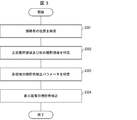
- FIG. 3 is a flowchart showing view angle correction processing of the display device 1 according to the present embodiment.
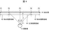
- FIG. 4 is a view showing the details of the front view area and the oblique view area according to the present embodiment.
- FIG. 4 shows a method of specifying the front view area and the oblique view area on the display unit 14 from the position of the viewer U. The details of the viewing angle correction process will be described below with reference to FIGS. 3 and 4.
- the viewer position specifying unit 11 specifies the position of the viewer U. That is, as shown in FIG. 4, the viewer position specifying unit 11 may be, for example, between the front position P3 of the viewer U on the screen of the display unit 14 and the screen of the display unit 14 and the viewer U Identify the distance L of
- the viewing angle correction parameter switching unit 12 specifies the front view area V1 and the oblique view areas V2 and V3. That is, as shown in FIG. 4, the viewing angle correction parameter switching unit 12 specifies the positions P2 and P4 from the front position P3, the distance L, and the angle ⁇ of the front view of the viewer U.
- the viewing angle correction parameter switching unit 12 specifies the range from the left end position P2 to the right end position P4 as the front visual field region V1.
- the view angle correction parameter switching unit 12 specifies a range from the left end position P1 of the screen of the display unit 14 to the left end position P2 of the front view area V1 as the oblique view area V2.
- the viewing angle correction parameter switching unit 12 specifies a range from the right end position P4 of the front view area V1 to the right end position P5 of the screen of the display unit 14 as the oblique view area V3.
- the oblique view area V2 does not exist.
- the right end position P4 of the front view area V1 is not on the left side of the right end position P5 of the screen, the oblique view area V3 does not exist.
- the viewing angle correction parameter switching unit 12 specifies the viewing angle correction parameters of the front visual field region V1 identified in step S302 and the oblique visual field regions V2 and V3.
- Step S304 The viewing angle correction unit 13 corrects the viewing angles of the display image in the front viewing region V1 and the oblique viewing regions V2 and V3 using the viewing angle correction parameters specified in step S303.
- the display position on the screen of the display unit 14 is divided into the front view area and the oblique view area according to the position of the viewer U, and the view angle correction parameter appropriate for each area Set According to the above, it is possible to improve both the front view from the viewer U and the oblique view.
- Embodiment 2 of the present invention will be described in detail with reference to FIGS. 5 to 7.
- symbol is appended and the description is not repeated.
- the display device 1a controls the degree of effectiveness of the view angle correction (the on / off / intensity of the zigzag processing) in the front view area according to the distance L between the liquid crystal panel and the viewer U. .
- the zigzag process is a process of displaying bright blue sub-pixels and dark blue sub-pixels in a staggered pattern on the screen of the liquid crystal display device.
- the display device 1a sets "viewing angle correction off" when the distance L is smaller than the threshold, and sets “viewing angle correction ON" when the distance L is equal to or larger than the threshold.
- FIG. 5 is a diagram showing the main configuration of the display device 1a according to the present embodiment.
- the display device 1a is a liquid crystal display device.
- the television receiver includes the display device 1a.
- the display device 1 includes a viewing angle correction unit 13, a display unit 14, a distance detection unit 15, and a control unit 16.
- the view angle correction unit 13 performs the view angle correction of the display image with respect to the front view area and the oblique view area with reference to the view angle correction parameter.
- the display unit 14 is a screen for displaying an image.
- the display unit 14 is divided into a front view area and an oblique view area according to the position of the viewer, and receives the view angle correction of the display image in each area from the view angle correction unit 13.
- the distance detection unit 15 detects the distance of the viewer from the screen.
- the distance detection unit 15 is configured of a distance sensor or the like.
- the control unit 16 corrects the viewing angle of the front view area by the viewing angle correction unit 13 Turn off.
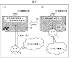
- FIG. 6 is a diagram showing an outline of on-off processing of viewing angle correction according to the present embodiment.
- FIG. 6 shows turning on / off of the viewing angle correction according to the distance L between the screen and the viewer U.
- the distance detection unit 15 is located at the top of the display unit 14 and at the center with respect to the lateral width.
- the control unit 16 turns on the viewing angle correction.
- the control unit 16 turns off the viewing angle correction.
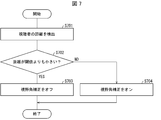
- FIG. 7 is a flowchart showing on-off processing of viewing angle correction of the display device 1a according to the present embodiment. The details of the on-off process of the viewing angle correction will be described below with reference to FIG.
- Step S701 The distance detection unit 15 detects the distance L between the screen and the viewer U.
- Step S702 The control unit 16 determines whether the distance L detected by the distance detection unit 15 is smaller than a threshold. If the distance L is smaller than the threshold (YES in step S702), the control unit 16 executes step 703. If the distance L is not smaller than the threshold (equal to or greater than the threshold) (NO in step S702), the control unit 16 executes step 704.
- Step S703 The control unit 16 turns on the viewing angle correction.
- Step S704 The control unit 16 turns off the viewing angle correction.
- control blocks in particular, the viewing angle correction parameter switching unit 12, the viewing angle correction unit 13, and the control unit 16 of the display devices 1 and 1a are logic circuits (hardware) formed in integrated circuits (IC chips) or the like. And may be realized by software.
- the display devices 1 and 1a each include a computer that executes instructions of a program that is software that implements each function.
- the computer includes, for example, at least one processor (control device) and at least one computer readable storage medium storing the program. Then, in the computer, the processor reads the program from the recording medium and executes the program to achieve the object of the present invention.
- a CPU Central Processing Unit
- the processor reads the program from the recording medium and executes the program to achieve the object of the present invention.
- a CPU Central Processing Unit
- the processor can be used as the processor.
- a recording medium a tape, a disk, a card, a semiconductor memory, a programmable logic circuit or the like can be used besides “a non-temporary tangible medium”, for example, a ROM (Read Only Memory).
- a RAM Random Access Memory
- the program may be supplied to the computer via any transmission medium (communication network, broadcast wave, etc.) capable of transmitting the program.
- any transmission medium communication network, broadcast wave, etc.
- one aspect of the present invention can also be realized in the form of a data signal embedded in a carrier wave in which the program is embodied by electronic transmission.
- the display device (1) refers to a viewing angle correction unit (13) that performs viewing angle correction of a display image with reference to a viewing angle correction parameter, and a viewer position specification that specifies the position of a viewer
- a viewing angle correction parameter switching unit that switches a viewing angle correction parameter between an area on the screen and another area according to the position of the viewer specified by the section (11) and the viewer position specifying section; And.
- the display quality of the device can be improved.
- the viewing angle correction parameter switching unit controls the front visual field (V1) and the oblique visual field (V2, V3) according to the position of the viewer.
- the viewing angle correction parameter may be switched between
- the front view and the oblique view of the viewer can be improved.
- a display device (1a) includes a viewing angle correction unit (13) that performs viewing angle correction of a display image, a distance detection unit (15) that detects a viewer's distance from the screen, And a control unit (16) for turning off the viewing angle correction by the viewing angle correction unit when the distance of the viewer from the screen detected by the distance detection unit is smaller than a predetermined distance.
- the display device when the distance of the viewer from the screen is smaller than the predetermined distance, the sense of resolution deterioration due to the view angle correction can be prevented by turning off the view angle correction. Display quality can be improved.
- a television receiver according to aspect 4 of the present invention includes the display device according to aspects 1 to 3 above.
- the display device may be realized by a computer.
- the display device is realized by the computer by operating the computer as each unit (software element) included in the display device.
- a control program of a display device and a computer readable recording medium recording the same also fall within the scope of the present invention.
Landscapes
- Engineering & Computer Science (AREA)
- Theoretical Computer Science (AREA)
- Physics & Mathematics (AREA)
- Computer Hardware Design (AREA)
- General Physics & Mathematics (AREA)
- Signal Processing (AREA)
- Multimedia (AREA)
- Chemical & Material Sciences (AREA)
- Crystallography & Structural Chemistry (AREA)
- Liquid Crystal Display Device Control (AREA)
- Control Of Indicators Other Than Cathode Ray Tubes (AREA)
- Controls And Circuits For Display Device (AREA)
- Transforming Electric Information Into Light Information (AREA)
Abstract
表示装置の表示品位を向上させる。表示装置(1)は、視野角補正パラメータを参照して表示画像の視野角補正を行う視野角補正部(13)と、視聴者の位置を特定する視聴者位置特定部(11)と、視聴者位置特定部が特定した視聴者の位置に応じて、画面内のある領域と他の領域とで視野角補正パラメータを切り替える視野角補正パラメータ切替部(12)と、を備えている。
Description
本発明は、表示装置、および、テレビジョン受像機に関する。
液晶表示装置は、赤(R)、緑(G)、青(B)の光の三原色に対応するサブ画素で構成されている。液晶表示装置には、従来から視野角(画面を正常に見ることが可能な角度)が劣化するという不具合がある。
その対策としては、視聴者が解像度劣化に気づきにくい青サブ画素を用いる方法がある。すなわち、液晶表示装置の画面において、明るい青サブ画素と、暗い青サブ画素とを千鳥パターン的に表示する処理(千鳥処理)により、それらの平均値を視聴者に見せることで所望の輝度を確保しつつ、正面視と、斜め視との色のずれが少ない表示(すなわち、視野角補正された表示)を実現している。特許文献1には、そのような表示の例が開示されている。
しかしながら、大画面パネルでは、次のような課題が発生する。
第一に、視聴者の位置がパネルに近づくので、画面上に、正面視野領域と、斜め視野領域とが同時に発生することが増える。このため、視聴者は、より近い位置で画面を見ることになる。その結果、視聴者の位置(視野の方向)によっては、視聴者の視野中においてパネルの視野角に差が出てしまうという問題がある。これは、一律の視野角補正パラメータでは、正面視野領域と、斜め視野領域との色シフトを同時に抑える(つまり、何れの視野領域にも有効なパラメータを設定する)ことが難しいためである。
第二に、視聴者が、視野角補正されたパネル表示画面に近づくと、「ぶつぶつ」感のある表示画面として認識されてしまう。このため、せっかくの大画面コンテンツの解像感が劣化してしまう。すなわち、大画面パネル表示においては、視聴者が画面に近づくことにより、「ぶつぶつ」感に気付き易くなるという問題がある。
本発明の一態様は、表示装置の表示品位を向上させることを目的とする。
上記第1の課題を解決するために、本発明の一態様に係る表示装置は、視野角補正パラメータを参照して表示画像の視野角補正を行う視野角補正部と、視聴者の位置を特定する視聴者位置特定部と、上記視聴者位置特定部が特定した視聴者の位置に応じて、画面内のある領域と他の領域とで視野角補正パラメータを切り替える視野角補正パラメータ切替部と、を備えている。
また、上記第2の課題を解決するために、本発明の一態様に係る表示装置は、表示画像の視野角補正を行う視野角補正部と、画面からの視聴者の距離を検出する距離検出部と、上記距離検出部が検出した画面からの視聴者の距離が、所定の距離よりも小さい場合に、上記視野角補正部による視野角補正をオフにする制御部と、を備えている。
本発明の一態様によれば、表示装置の表示品位を向上させることができるとの効果を奏する。
〔実施形態1〕
以下、本発明の実施形態1について、図1から図4を用いて詳細に説明する。本実施形態に係る表示装置1は、液晶パネルに対する視聴者Uの相対位置をカメラ等のセンサで検出し、当該相対位置によって特定される、液晶パネルの表示画面内の各領域が、視聴者Uから適切に見えるように、視野角補正パラメータを設定する。
以下、本発明の実施形態1について、図1から図4を用いて詳細に説明する。本実施形態に係る表示装置1は、液晶パネルに対する視聴者Uの相対位置をカメラ等のセンサで検出し、当該相対位置によって特定される、液晶パネルの表示画面内の各領域が、視聴者Uから適切に見えるように、視野角補正パラメータを設定する。
視野角補正では、例えば、明るいサブ画素と暗いサブ画素との輝度差が調整される。視野角補正パラメータの一例として、明るいサブ画素と暗いサブ画素との輝度差が挙げられる。
表示画面内の領域には、正面視野領域と、斜め視野領域とが含まれる。正面視野領域は、表示画面のうち、視聴者Uの正面視野に対応する画面領域である。斜め視野領域は、表示画面のうち、正面視野領域以外の画面領域である。
(表示装置1の構成)
図1は、本実施形態に係る表示装置1の要部構成を示す図である。表示装置1は、液晶表示装置である。テレビジョン受像機は、表示装置1を備えている。
図1は、本実施形態に係る表示装置1の要部構成を示す図である。表示装置1は、液晶表示装置である。テレビジョン受像機は、表示装置1を備えている。
図1に示すように、表示装置1は、視聴者位置特定部11、視野角補正パラメータ切替部12、視野角補正部13、および、表示部14を備えている。視聴者位置特定部11は、画面に対する視聴者の相対位置を特定する。視聴者位置特定部11は、位置センサ等で構成される。視野角補正パラメータ切替部12は、視聴者位置特定部11が特定した視聴者Uの位置に応じて、画面内の正面視野領域(ある領域)と、斜め視野領域(他の領域)とで視野角補正パラメータを切り替える。
視野角補正部13は、視野角補正パラメータを参照して、各領域に対して表示画像の視野角補正を行う。表示部14は、映像を表示する画面である。表示部14は、視聴者の位置に応じて正面視野領域と、斜め視野領域とに分割され、各領域において視野角補正部13から表示画像の視野角補正を受ける。
(視野角補正処理の概要)
図2は、本実施形態に係る視野角補正処理の概要を示す図である。図2は、視聴者Uの位置に応じて、正面視野、および、斜め視野が変化することを示す。視聴者位置特定部11は、表示部14の上部、かつ、横幅に対して中心に設置される。
図2は、本実施形態に係る視野角補正処理の概要を示す図である。図2は、視聴者Uの位置に応じて、正面視野、および、斜め視野が変化することを示す。視聴者位置特定部11は、表示部14の上部、かつ、横幅に対して中心に設置される。
図2(a)では、視聴者Uが表示部14の横幅に対して中心に位置している。この場合、視聴者Uの正面視野は表示部14の中心を挟んで存在し、視聴者Uの斜め視野は正面視野の左右両側に存在する。視野角補正パラメータ切替部12は、中心の正面視野領域には正面視野特化視野角補正パラメータを設定し、左右の斜め視野領域には斜め視野特化視野角補正パラメータを設定する。
図2(b)では、視聴者Uが表示部14の横幅に対して右寄りに位置している。この場合、視聴者Uの正面視野は表示部14の右側に存在し、視聴者Uの斜め視野は表示部14の左側に存在する。視野角補正パラメータ切替部12は、右側の正面視野領域には正面視野特化視野角補正パラメータを設定し、左側の斜め視野領域には斜め視野特化視野角補正パラメータを設定する。
(視野角補正処理の詳細)
図3は、本実施形態に係る表示装置1の視野角補正処理を示すフローチャートである。図4は、本実施形態に係る正面視野領域、および、斜め視野領域の詳細を示す図である。図4は、視聴者Uの位置から、表示部14上における正面視野領域、および、斜め視野領域を特定する方法を示す。以下、図3および図4を参照して、視野角補正処理の詳細を説明する。
図3は、本実施形態に係る表示装置1の視野角補正処理を示すフローチャートである。図4は、本実施形態に係る正面視野領域、および、斜め視野領域の詳細を示す図である。図4は、視聴者Uの位置から、表示部14上における正面視野領域、および、斜め視野領域を特定する方法を示す。以下、図3および図4を参照して、視野角補正処理の詳細を説明する。
(ステップS301)
表示装置1において、視聴者位置特定部11は、視聴者Uの位置を特定する。すなわち、図4に示すように、視聴者位置特定部11は、例えば、表示部14の画面上の、視聴者Uの正面位置P3、および、表示部14の画面と、視聴者Uとの間の距離Lを特定する。
表示装置1において、視聴者位置特定部11は、視聴者Uの位置を特定する。すなわち、図4に示すように、視聴者位置特定部11は、例えば、表示部14の画面上の、視聴者Uの正面位置P3、および、表示部14の画面と、視聴者Uとの間の距離Lを特定する。
(ステップS302)
視野角補正パラメータ切替部12は、正面視野領域V1、および、斜め視野領域V2、V3を特定する。すなわち、図4に示すように、視野角補正パラメータ切替部12は、正面位置P3、距離L、および、視聴者Uの正面視野の角度θから、位置P2、および、P4を特定する。
視野角補正パラメータ切替部12は、正面視野領域V1、および、斜め視野領域V2、V3を特定する。すなわち、図4に示すように、視野角補正パラメータ切替部12は、正面位置P3、距離L、および、視聴者Uの正面視野の角度θから、位置P2、および、P4を特定する。
これにより、視野角補正パラメータ切替部12は、左端位置P2から右端位置P4までの範囲を、正面視野領域V1として特定する。次に、視野角補正パラメータ切替部12は、表示部14の画面の左端位置P1から正面視野領域V1の左端位置P2までの範囲を、斜め視野領域V2として特定する。そして、視野角補正パラメータ切替部12は、正面視野領域V1の右端位置P4から表示部14の画面の右端位置P5までの範囲を、斜め視野領域V3として特定する。
ただし、正面視野領域V1の左端位置P2が画面の左端位置P1よりも右側にない場合には、斜め視野領域V2は存在しない。また、正面視野領域V1の右端位置P4が画面の右端位置P5よりも左側にない場合には、斜め視野領域V3は存在しない。
(ステップS303)
視野角補正パラメータ切替部12は、ステップS302で特定した正面視野領域V1、および、斜め視野領域V2、V3の視野角補正パラメータを特定する。
視野角補正パラメータ切替部12は、ステップS302で特定した正面視野領域V1、および、斜め視野領域V2、V3の視野角補正パラメータを特定する。
(ステップS304)
視野角補正部13は、ステップS303で特定した視野角補正パラメータを用いて、正面視野領域V1、および、斜め視野領域V2、V3における表示画像の視野角を補正する。
視野角補正部13は、ステップS303で特定した視野角補正パラメータを用いて、正面視野領域V1、および、斜め視野領域V2、V3における表示画像の視野角を補正する。
(実施形態1の効果)
本実施形態によれば、視聴者Uの位置に応じて、表示部14の画面上の表示位置を、正面視野領域と、斜め視野領域とに分割して、各領域に適切な視野角補正パラメータを設定する。上記によれば、視聴者Uからの正面視野、および、斜め視野の両方を向上させることができる。
本実施形態によれば、視聴者Uの位置に応じて、表示部14の画面上の表示位置を、正面視野領域と、斜め視野領域とに分割して、各領域に適切な視野角補正パラメータを設定する。上記によれば、視聴者Uからの正面視野、および、斜め視野の両方を向上させることができる。
〔実施形態2〕
以下、本発明の実施形態2について、図5から図7を用いて詳細に説明する。なお、説明の便宜上、実施形態1にて説明した部材と同じ機能を有する部材については、同じ符号を付記し、その説明を繰り返さない。
以下、本発明の実施形態2について、図5から図7を用いて詳細に説明する。なお、説明の便宜上、実施形態1にて説明した部材と同じ機能を有する部材については、同じ符号を付記し、その説明を繰り返さない。
本実施形態に係る表示装置1aは、液晶パネルと、視聴者Uとの間の距離Lに応じて、正面視野領域における視野角補正の効き具合(千鳥処理のオン/オフ/強度)を制御する。千鳥処理は、液晶表示装置の画面において、明るい青サブ画素と、暗い青サブ画素とを千鳥パターン的に表示する処理である。表示装置1aは、距離Lが閾値よりも小さい場合には「視野角補正オフ」にし、距離Lが閾値以上の場合は「視野角補正オン」にする。
(表示装置1aの構成)
図5は、本実施形態に係る表示装置1aの要部構成を示す図である。表示装置1aは、液晶表示装置である。テレビジョン受像機は、表示装置1aを備えている。
図5は、本実施形態に係る表示装置1aの要部構成を示す図である。表示装置1aは、液晶表示装置である。テレビジョン受像機は、表示装置1aを備えている。
図5に示すように、表示装置1は、視野角補正部13、表示部14、距離検出部15、および、制御部16を備えている。視野角補正部13は、視野角補正パラメータを参照して、正面視野領域、および、斜め視野領域に対して表示画像の視野角補正を行う。表示部14は、映像を表示する画面である。表示部14は、視聴者の位置に応じて正面視野領域と、斜め視野領域とに分割され、視野角補正部13から各領域において表示画像の視野角補正を受ける。
距離検出部15は、画面からの視聴者の距離を検出する。距離検出部15は、距離センサ等で構成される。制御部16は、距離検出部15が検出した、表示部14の画面から視聴者Uまでの距離が、所定の距離よりも小さい場合に、視野角補正部13による、正面視野領域の視野角補正をオフにする。
(視野角補正のオンオフ処理の概要)
図6は、本実施形態に係る視野角補正のオンオフ処理の概要を示す図である。図6は、画面と、視聴者Uとの間の距離Lに応じて、視野角補正をオンオフすることを示す。距離検出部15は、表示部14の上部、かつ、横幅に対して中央に位置する。
図6は、本実施形態に係る視野角補正のオンオフ処理の概要を示す図である。図6は、画面と、視聴者Uとの間の距離Lに応じて、視野角補正をオンオフすることを示す。距離検出部15は、表示部14の上部、かつ、横幅に対して中央に位置する。
図2(a)では、画面と、視聴者Uとの間の距離Lが長い。この場合、制御部16は、視野角補正をオンする。
図2(b)では、画面と、視聴者Uとの間の距離Lが短い。この場合、制御部16は、視野角補正をオフする。
(視野角補正のオンオフ処理の詳細)
図7は、本実施形態に係る表示装置1aの視野角補正のオンオフ処理を示すフローチャートである。以下、図7を参照して、視野角補正のオンオフ処理の詳細を説明する。
図7は、本実施形態に係る表示装置1aの視野角補正のオンオフ処理を示すフローチャートである。以下、図7を参照して、視野角補正のオンオフ処理の詳細を説明する。
(ステップS701)
距離検出部15は、画面と、視聴者Uとの間の距離Lを検出する。
距離検出部15は、画面と、視聴者Uとの間の距離Lを検出する。
(ステップS702)
制御部16は、距離検出部15が検出した距離Lが閾値よりも小さいか否かを判定する。距離Lが閾値よりも小さい場合(ステップS702のYES)、制御部16は、ステップ703を実行する。距離Lが閾値よりも小さくない(閾値以上である)場合(ステップS702のNO)、制御部16は、ステップ704を実行する。
制御部16は、距離検出部15が検出した距離Lが閾値よりも小さいか否かを判定する。距離Lが閾値よりも小さい場合(ステップS702のYES)、制御部16は、ステップ703を実行する。距離Lが閾値よりも小さくない(閾値以上である)場合(ステップS702のNO)、制御部16は、ステップ704を実行する。
(ステップS703)
制御部16は、視野角補正をオンする。
制御部16は、視野角補正をオンする。
(ステップS704)
制御部16は、視野角補正をオフする。
制御部16は、視野角補正をオフする。
(実施形態2の効果)
本実施形態によれば、画面と、視聴者Uとの間の距離Lが閾値よりも小さい場合に、千鳥パターンによる「ぶつぶつ」が表示されないので、視聴者Uは解像度劣化を感じなくなる。一方、画面と、視聴者Uとの間の距離Lが閾値以上の場合に、通常通り視野角補正を有効にして、色シフトを防ぐことができる。その結果、液晶パネルの視野角補正機能を担保しつつ、8K解像度表示ならではの解像度を活かした表示が可能になる。上記によれば、視聴者Uの正面視野における解像度の劣化感を防止することができる。
本実施形態によれば、画面と、視聴者Uとの間の距離Lが閾値よりも小さい場合に、千鳥パターンによる「ぶつぶつ」が表示されないので、視聴者Uは解像度劣化を感じなくなる。一方、画面と、視聴者Uとの間の距離Lが閾値以上の場合に、通常通り視野角補正を有効にして、色シフトを防ぐことができる。その結果、液晶パネルの視野角補正機能を担保しつつ、8K解像度表示ならではの解像度を活かした表示が可能になる。上記によれば、視聴者Uの正面視野における解像度の劣化感を防止することができる。
〔ソフトウェアによる実現例〕
表示装置1、1aの制御ブロック(特に、視野角補正パラメータ切替部12、視野角補正部13、および、制御部16)は、集積回路(ICチップ)等に形成された論理回路(ハードウェア)によって実現してもよいし、ソフトウェアによって実現してもよい。
表示装置1、1aの制御ブロック(特に、視野角補正パラメータ切替部12、視野角補正部13、および、制御部16)は、集積回路(ICチップ)等に形成された論理回路(ハードウェア)によって実現してもよいし、ソフトウェアによって実現してもよい。
後者の場合、表示装置1、1aは、各機能を実現するソフトウェアであるプログラムの命令を実行するコンピュータを備えている。このコンピュータは、例えば少なくとも1つのプロセッサ(制御装置)を備えていると共に、上記プログラムを記憶したコンピュータ読み取り可能な少なくとも1つの記録媒体を備えている。そして、上記コンピュータにおいて、上記プロセッサが上記プログラムを上記記録媒体から読み取って実行することにより、本発明の目的が達成される。上記プロセッサとしては、例えばCPU(Central Processing Unit)を用いることができる。上記記録媒体としては、「一時的でない有形の媒体」、例えば、ROM(Read Only Memory)等の他、テープ、ディスク、カード、半導体メモリ、プログラマブルな論理回路などを用いることができる。また、上記プログラムを展開するRAM(Random Access Memory)などをさらに備えていてもよい。また、上記プログラムは、該プログラムを伝送可能な任意の伝送媒体(通信ネットワークや放送波等)を介して上記コンピュータに供給されてもよい。なお、本発明の一態様は、上記プログラムが電子的な伝送によって具現化された、搬送波に埋め込まれたデータ信号の形態でも実現され得る。
〔まとめ〕
本発明の態様1に係る表示装置(1)は、視野角補正パラメータを参照して表示画像の視野角補正を行う視野角補正部(13)と、視聴者の位置を特定する視聴者位置特定部(11)と、上記視聴者位置特定部が特定した視聴者の位置に応じて、画面内のある領域と他の領域とで視野角補正パラメータを切り替える視野角補正パラメータ切替部と(12)、を備えている。
本発明の態様1に係る表示装置(1)は、視野角補正パラメータを参照して表示画像の視野角補正を行う視野角補正部(13)と、視聴者の位置を特定する視聴者位置特定部(11)と、上記視聴者位置特定部が特定した視聴者の位置に応じて、画面内のある領域と他の領域とで視野角補正パラメータを切り替える視野角補正パラメータ切替部と(12)、を備えている。
上記によれば、表示装置において、視聴者の位置に応じて、画面内のある領域と他の領域とで視野角補正パラメータを切り替えることにより、領域間の視野角の差を補正できるので、表示装置の表示品位を向上させることができる。
本発明の態様2に係る表示装置は、上記態様1において、上記視野角補正パラメータ切替部が、上記視聴者の位置に応じて、正面視野領域(V1)と、斜め視野領域(V2、V3)とで視野角補正パラメータを切り替えることとしてもよい。
上記によれば、表示装置において、視聴者の正面視野および斜め視野を向上させることができる。
本発明の態様3に係る表示装置(1a)は、表示画像の視野角補正を行う視野角補正部(13)と、画面からの視聴者の距離を検出する距離検出部(15)と、上記距離検出部が検出した画面からの視聴者の距離が、所定の距離よりも小さい場合に、上記視野角補正部による視野角補正をオフにする制御部(16)と、を備えている。
上記によれば、表示装置において、画面からの視聴者の距離が所定の距離よりも小さい場合に、視野角補正をオフにすることにより、視野角補正による解像度劣化感を防止できるので、表示装置の表示品位を向上させることができる。
本発明の態様4に係るテレビジョン受像機は、上記態様1から3における表示装置を備えている。
本発明の各態様に係る表示装置は、コンピュータによって実現してもよく、この場合には、コンピュータを上記表示装置が備える各部(ソフトウェア要素)として動作させることにより上記表示装置をコンピュータにて実現させる表示装置の制御プログラム、およびそれを記録したコンピュータ読み取り可能な記録媒体も、本発明の範疇に入る。
本発明は上述した各実施形態に限定されるものではなく、請求項に示した範囲で種々の変更が可能であり、異なる実施形態にそれぞれ開示された技術的手段を適宜組み合わせて得られる実施形態についても本発明の技術的範囲に含まれる。さらに、各実施形態にそれぞれ開示された技術的手段を組み合わせることにより、新しい技術的特徴を形成することができる。
1、1a 表示装置
11 視聴者位置特定部
12 視野角補正パラメータ切替部
13 視野角補正部
14 表示部
15 距離検出部
16 制御部
V1 正面視野領域
V2、V3 斜め視野領域
11 視聴者位置特定部
12 視野角補正パラメータ切替部
13 視野角補正部
14 表示部
15 距離検出部
16 制御部
V1 正面視野領域
V2、V3 斜め視野領域
Claims (4)
- 視野角補正パラメータを参照して表示画像の視野角補正を行う視野角補正部と、
視聴者の位置を特定する視聴者位置特定部と、
上記視聴者位置特定部が特定した視聴者の位置に応じて、画面内のある領域と他の領域とで視野角補正パラメータを切り替える視野角補正パラメータ切替部と、
を備えていることを特徴とする表示装置。 - 上記視野角補正パラメータ切替部は、上記視聴者の位置に応じて、正面視野領域と、斜め視野領域とで視野角補正パラメータを切り替える
ことを特徴とする請求項1に記載の表示装置。 - 表示画像の視野角補正を行う視野角補正部と、
画面からの視聴者の距離を検出する距離検出部と、
上記距離検出部が検出した画面からの視聴者の距離が、所定の距離よりも小さい場合に、上記視野角補正部による視野角補正をオフにする制御部と、
を備えていることを特徴とする表示装置。 - 請求項1から3の何れか1項に記載の表示装置を備えていることを特徴とするテレビジョン受像機。
Applications Claiming Priority (2)
| Application Number | Priority Date | Filing Date | Title |
|---|---|---|---|
| JP2017164678A JP2019045523A (ja) | 2017-08-29 | 2017-08-29 | 表示装置、および、テレビジョン受像機 |
| JP2017-164678 | 2017-08-29 |
Publications (1)
| Publication Number | Publication Date |
|---|---|
| WO2019044179A1 true WO2019044179A1 (ja) | 2019-03-07 |
Family
ID=65524980
Family Applications (1)
| Application Number | Title | Priority Date | Filing Date |
|---|---|---|---|
| PCT/JP2018/025829 Ceased WO2019044179A1 (ja) | 2017-08-29 | 2018-07-09 | 表示装置、および、テレビジョン受像機 |
Country Status (2)
| Country | Link |
|---|---|
| JP (1) | JP2019045523A (ja) |
| WO (1) | WO2019044179A1 (ja) |
Cited By (1)
| Publication number | Priority date | Publication date | Assignee | Title |
|---|---|---|---|---|
| CN111640404A (zh) * | 2020-06-10 | 2020-09-08 | 昆山龙腾光电股份有限公司 | 宽窄视角切换电路及其显示装置 |
Citations (3)
| Publication number | Priority date | Publication date | Assignee | Title |
|---|---|---|---|---|
| US20050117186A1 (en) * | 2003-11-21 | 2005-06-02 | Baoxin Li | Liquid crystal display with adaptive color |
| JP2008242342A (ja) * | 2007-03-29 | 2008-10-09 | Victor Co Of Japan Ltd | テレビジョン装置 |
| WO2012077601A1 (ja) * | 2010-12-08 | 2012-06-14 | シャープ株式会社 | 画像処理装置、画像処理方法、および表示装置 |
-
2017
- 2017-08-29 JP JP2017164678A patent/JP2019045523A/ja active Pending
-
2018
- 2018-07-09 WO PCT/JP2018/025829 patent/WO2019044179A1/ja not_active Ceased
Patent Citations (3)
| Publication number | Priority date | Publication date | Assignee | Title |
|---|---|---|---|---|
| US20050117186A1 (en) * | 2003-11-21 | 2005-06-02 | Baoxin Li | Liquid crystal display with adaptive color |
| JP2008242342A (ja) * | 2007-03-29 | 2008-10-09 | Victor Co Of Japan Ltd | テレビジョン装置 |
| WO2012077601A1 (ja) * | 2010-12-08 | 2012-06-14 | シャープ株式会社 | 画像処理装置、画像処理方法、および表示装置 |
Cited By (1)
| Publication number | Priority date | Publication date | Assignee | Title |
|---|---|---|---|---|
| CN111640404A (zh) * | 2020-06-10 | 2020-09-08 | 昆山龙腾光电股份有限公司 | 宽窄视角切换电路及其显示装置 |
Also Published As
| Publication number | Publication date |
|---|---|
| JP2019045523A (ja) | 2019-03-22 |
Similar Documents
| Publication | Publication Date | Title |
|---|---|---|
| CN102971663B (zh) | 用于增大对比度和分辨率的使用无滤波器的lcd的高动态范围显示器 | |
| US9779651B2 (en) | Image processing device, method, and program, and image display device | |
| US8648972B2 (en) | Switchable two dimensional / three dimensional display (2D/3D display) comprising a switchable barrier having a three dimensional image control area and a first black matrix and a second black matrix that surrounds the three dimensional image control area | |
| CN102187267B (zh) | 用于处理图像数据以由显示装置显示的方法和设备 | |
| JPH10268309A (ja) | 液晶表示装置 | |
| JP2008191269A (ja) | 液晶表示装置の駆動装置 | |
| US20090079680A1 (en) | Dual-view display device | |
| US12131093B2 (en) | Method for eliminating splicing gap of splicing screens and display device | |
| US20080198218A1 (en) | Stereoscopic image format transformation method applied to display system | |
| US8797247B2 (en) | Perceived display resolution of a color electronic matrix display | |
| US20100156950A1 (en) | Color filter substrate and display apparatus having the same | |
| US10043442B2 (en) | Display device, and method for modifying image displaying on the display device | |
| US11260490B2 (en) | Edge processing method for display panel having irregular edge and display panel | |
| TW201835891A (zh) | 用於異形顯示幕的像素單元的驅動方法和驅動裝置 | |
| WO2019044179A1 (ja) | 表示装置、および、テレビジョン受像機 | |
| KR100968452B1 (ko) | 영상처리장치 및 그 제어방법 | |
| JP2019040135A (ja) | 表示装置及びテレビジョン受信装置 | |
| JP2012237903A (ja) | 輝度制御装置、画像表示装置、液晶テレビ受信機、輝度制御方法、コンピュータプログラム及び記録媒体 | |
| JP2014032338A (ja) | 画像表示装置及び画像表示方法 | |
| CN111386565B (zh) | 光场显示方法、装置、设备和记录介质 | |
| JP7751521B2 (ja) | 表示装置 | |
| EP2737709B1 (en) | Autostereoscopic display system | |
| CN117475939A (zh) | 基于单色和彩色图像的背光亮度自动调节方法及装置 | |
| US20070279356A1 (en) | Picture Display Apparatus | |
| KR102033389B1 (ko) | 어시스트 패턴을 포함하는 마스크 |
Legal Events
| Date | Code | Title | Description |
|---|---|---|---|
| 121 | Ep: the epo has been informed by wipo that ep was designated in this application |
Ref document number: 18852248 Country of ref document: EP Kind code of ref document: A1 |
|
| NENP | Non-entry into the national phase |
Ref country code: DE |
|
| 122 | Ep: pct application non-entry in european phase |
Ref document number: 18852248 Country of ref document: EP Kind code of ref document: A1 |