WO2019031123A1 - 空調装置 - Google Patents
空調装置 Download PDFInfo
- Publication number
- WO2019031123A1 WO2019031123A1 PCT/JP2018/025536 JP2018025536W WO2019031123A1 WO 2019031123 A1 WO2019031123 A1 WO 2019031123A1 JP 2018025536 W JP2018025536 W JP 2018025536W WO 2019031123 A1 WO2019031123 A1 WO 2019031123A1
- Authority
- WO
- WIPO (PCT)
- Prior art keywords
- refrigerant
- air
- heat
- heat exchanger
- outside air
- Prior art date
- Legal status (The legal status is an assumption and is not a legal conclusion. Google has not performed a legal analysis and makes no representation as to the accuracy of the status listed.)
- Ceased
Links
Images


Classifications
-
- B—PERFORMING OPERATIONS; TRANSPORTING
- B60—VEHICLES IN GENERAL
- B60H—ARRANGEMENTS OF HEATING, COOLING, VENTILATING OR OTHER AIR-TREATING DEVICES SPECIALLY ADAPTED FOR PASSENGER OR GOODS SPACES OF VEHICLES
- B60H1/00—Heating, cooling or ventilating [HVAC] devices
- B60H1/02—Heating, cooling or ventilating [HVAC] devices the heat being derived from the propulsion plant
- B60H1/04—Heating, cooling or ventilating [HVAC] devices the heat being derived from the propulsion plant from cooling liquid of the plant
- B60H1/08—Heating, cooling or ventilating [HVAC] devices the heat being derived from the propulsion plant from cooling liquid of the plant from other radiator than main radiator
-
- B—PERFORMING OPERATIONS; TRANSPORTING
- B60—VEHICLES IN GENERAL
- B60H—ARRANGEMENTS OF HEATING, COOLING, VENTILATING OR OTHER AIR-TREATING DEVICES SPECIALLY ADAPTED FOR PASSENGER OR GOODS SPACES OF VEHICLES
- B60H1/00—Heating, cooling or ventilating [HVAC] devices
- B60H1/22—Heating, cooling or ventilating [HVAC] devices the heat being derived otherwise than from the propulsion plant
-
- B—PERFORMING OPERATIONS; TRANSPORTING
- B60—VEHICLES IN GENERAL
- B60H—ARRANGEMENTS OF HEATING, COOLING, VENTILATING OR OTHER AIR-TREATING DEVICES SPECIALLY ADAPTED FOR PASSENGER OR GOODS SPACES OF VEHICLES
- B60H1/00—Heating, cooling or ventilating [HVAC] devices
- B60H1/32—Cooling devices
-
- F—MECHANICAL ENGINEERING; LIGHTING; HEATING; WEAPONS; BLASTING
- F25—REFRIGERATION OR COOLING; COMBINED HEATING AND REFRIGERATION SYSTEMS; HEAT PUMP SYSTEMS; MANUFACTURE OR STORAGE OF ICE; LIQUEFACTION SOLIDIFICATION OF GASES
- F25B—REFRIGERATION MACHINES, PLANTS OR SYSTEMS; COMBINED HEATING AND REFRIGERATION SYSTEMS; HEAT PUMP SYSTEMS
- F25B1/00—Compression machines, plants or systems with non-reversible cycle
-
- F—MECHANICAL ENGINEERING; LIGHTING; HEATING; WEAPONS; BLASTING
- F25—REFRIGERATION OR COOLING; COMBINED HEATING AND REFRIGERATION SYSTEMS; HEAT PUMP SYSTEMS; MANUFACTURE OR STORAGE OF ICE; LIQUEFACTION SOLIDIFICATION OF GASES
- F25B—REFRIGERATION MACHINES, PLANTS OR SYSTEMS; COMBINED HEATING AND REFRIGERATION SYSTEMS; HEAT PUMP SYSTEMS
- F25B29/00—Combined heating and refrigeration systems, e.g. operating alternately or simultaneously
Definitions
- the present disclosure relates to an air conditioner that can perform cooling and heating.
- Patent Document 1 describes an air conditioner having a refrigeration cycle.
- the refrigerant circuit is switched between the cooling mode and the heating mode, the outdoor heat exchanger functions as a radiator in the cooling mode, and the outdoor heat exchanger functions as the evaporator in the heating mode.
- the position on the Mollier diagram of the outdoor heat exchanger is high in the cooling mode and low in the heating mode.
- the outdoor heat exchanger functions as a radiator or functions as an evaporator according to the target blowing temperature. That is, in the dehumidifying and heating mode, the position on the Mollier diagram of the outdoor heat exchanger is set to a high pressure or a low pressure.
- the pressure adjustment valve and the switching valve are required in the refrigerant circuit, and the circuit and control are easily complicated.
- the outdoor heat exchanger functions as the evaporator in the heating mode, but the heat absorption capacity of the outdoor heat exchanger is insufficient, which tends to cause the heating capacity to be insufficient.
- An object of the present disclosure is to simplify the configuration of an air conditioner that can switch between a heating mode, a cooling mode, and a dehumidifying heating mode.
- Another object of the present disclosure is to improve the heating capacity of an air conditioner that can switch between the heating mode, the cooling mode, and the dehumidifying heating mode.
- An air conditioner is: A compressor that sucks, compresses and discharges the refrigerant; An air heating unit that heats the refrigerant discharged from the compressor and uses the heat of the refrigerant to heat the air blown into the space to be air conditioned; An air heating amount adjustment unit that adjusts the heating amount of air in the air heating unit; A first pressure reducing unit disposed on the refrigerant outlet side of the air heating unit and on the refrigerant suction side of the compressor to reduce the pressure of the refrigerant; A refrigerant outside air heat exchanger that exchanges heat between the refrigerant flowing out of the first pressure reducing section and the outside air; A second decompression unit that decompresses the refrigerant heat-exchanged by the refrigerant outside air heat exchanger; An air-cooling heat exchanger that cools air by heat exchange between the refrigerant flowing out of the second decompression unit and the air before being heated by the air heating unit; A third pressure reduction unit
- the first pressure reducing unit is capable of switching between the state in which the refrigerant dissipates heat to the outside air by the refrigerant outside air heat exchanger, and the state in which the refrigerant absorbs heat from the outside air by the refrigerant outside air heat exchanger.
- the refrigerant flow switching unit causes the refrigerant to flow to the low-pressure refrigerant heat medium heat exchanger.
- the refrigerant cools the air in the air cooling heat exchanger, and the refrigerant radiates the outside air in the refrigerant outside air heat exchanger, whereby the cooling mode can be realized.
- the refrigerant absorbs heat from the outside air in the refrigerant outside air heat exchanger, and the air heating unit heats the air using heat of the refrigerant to realize the heating mode.
- a refrigerant cools air with a heat exchanger for air cooling, and a dehumidification heating mode is realizable by heating air using heat of a refrigerant in an air heating part.
- the refrigerant flows to the low pressure side refrigerant heat medium heat exchanger, the refrigerant can absorb heat from the heat medium in the low pressure side refrigerant heat medium heat exchanger. Therefore, since it is not necessary to frequently switch the high and low pressure of the refrigerant outside air heat exchanger at the time of the dehumidifying and heating mode, the operation and control can be simplified.
- An air conditioner is: A compressor that sucks, compresses and discharges the refrigerant; An air heating unit that heats the refrigerant discharged from the compressor and uses the heat of the refrigerant to heat the air blown into the space to be air conditioned; An air heating amount adjustment unit that adjusts the heating amount of air in the air heating unit; A first pressure reducing unit disposed on the refrigerant outlet side of the air heating unit and on the refrigerant suction side of the compressor to reduce the pressure of the refrigerant; A refrigerant outside air heat exchanger that exchanges heat between the refrigerant flowing out of the first pressure reducing section and the outside air; A second decompression unit that decompresses the refrigerant heat-exchanged by the refrigerant outside air heat exchanger; An air-cooling heat exchanger that cools air by heat exchange between the refrigerant flowing out of the second decompression unit and the air before being heated by the air heating unit; A third pressure reduction unit that
- the first pressure reducing unit is capable of switching between the state in which the refrigerant dissipates heat to the outside air by the refrigerant outside air heat exchanger, and the state in which the refrigerant absorbs heat from the outside air by the refrigerant outside air heat exchanger.
- the refrigerant outside air heat exchanger has a refrigerant outside air heat exchange unit that exchanges heat between the refrigerant and the outside air
- the heat medium open air heat exchanger has a low-temperature heat medium open air heat exchange section for exchanging heat between the heat medium and the outside air
- At least one heat exchange portion of the refrigerant outside air heat exchange portion and the low temperature heat medium outside air heat exchange portion has a portion which does not polymerize in the flow direction of the other heat exchange portion and the outside air
- the refrigerant flow switching unit causes the refrigerant to flow to the low-pressure refrigerant heat medium heat exchanger when the refrigerant is absorbed from the outside air by the refrigerant outside air heat exchanger and the air is heated by the air heating unit.
- the refrigerant cools the air in the air cooling heat exchanger, and the refrigerant radiates the outside air in the refrigerant outside air heat exchanger, whereby the cooling mode can be realized.
- the refrigerant absorbs heat from the outside air in the refrigerant outside air heat exchanger, and the air heating unit heats the air using heat of the refrigerant to realize the heating mode.
- the refrigerant can absorb heat from the heat medium in the low pressure side refrigerant heat medium heat exchanger.
- the refrigerant outside air heat exchange portion and the low temperature heat medium outside air heat exchange portion has a portion not polymerized in the flow direction of the other heat exchange portion and the outside air, the refrigerant outside air heat exchange It is possible to increase the heat absorption amount by increasing the heat exchange area of the part and the low temperature heat medium external air heat exchange part. Therefore, the heating performance can be improved.
- the vehicle air conditioner 1 shown in FIGS. 1 and 2 is an air conditioner that adjusts the vehicle interior space (in other words, the air conditioning target space) to an appropriate temperature.
- the vehicle air conditioner 1 has a refrigeration cycle apparatus 10.
- the refrigeration cycle apparatus 10 is mounted on a hybrid vehicle that obtains driving force for vehicle traveling from an engine (in other words, an internal combustion engine) and a traveling electric motor.
- the hybrid vehicle of the present embodiment is configured as a plug-in hybrid vehicle capable of charging a battery (in other words, an on-board battery) mounted on the vehicle with electric power supplied from an external power supply (in other words, a commercial power supply) It is done.
- a battery in other words, an on-board battery
- an external power supply in other words, a commercial power supply
- a lithium ion battery can be used as the battery.
- the driving force output from the engine is used not only for driving the vehicle but also for operating the generator.
- the electric power generated by the generator and the electric power supplied from the external power supply can be stored in the battery, and the electric power stored in the battery constitutes the refrigerating cycle device 10 as well as the electric motor for traveling. It is supplied to various in-vehicle devices including electric component devices.
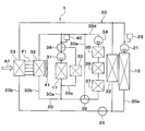
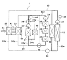
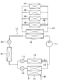
- the refrigeration cycle apparatus 10 includes a compressor 11, a condenser 12, a first expansion valve 80, an outdoor heat exchanger 81, a second expansion valve 13, an air cooling evaporator 14, a constant pressure valve 15, a third expansion valve 16, and cooling.
- This is a vapor compression type refrigerator equipped with a water cooling evaporator 17.
- a fluorocarbon-based refrigerant is used as the refrigerant, and a subcritical refrigeration cycle in which the high-pressure side refrigerant pressure does not exceed the critical pressure of the refrigerant is configured.
- the refrigeration cycle apparatus 10 includes a series refrigerant flow path 10a, a first parallel refrigerant flow path 10b, and a second parallel refrigerant flow path 10c.
- the series refrigerant flow path 10a, the first parallel refrigerant flow path 10b, and the second parallel refrigerant flow path 10c are flow paths through which the refrigerant flows.
- a refrigerant circulation circuit in which the refrigerant circulates is formed by the series refrigerant flow passage 10a, the first parallel refrigerant flow passage 10b, and the second parallel refrigerant flow passage 10c.
- the first parallel refrigerant flow passage 10 b and the second parallel refrigerant flow passage 10 c are connected to the series refrigerant flow passage 10 a so that the refrigerant flows in parallel to each other.
- the compressor 11, the condenser 12, the first expansion valve 80, and the outdoor heat exchanger 81 are arranged in series in this order in the refrigerant flow in the series refrigerant flow path 10a.
- the second expansion valve 13 In the first parallel refrigerant flow passage 10b, the second expansion valve 13, the air cooling evaporator 14 and the constant pressure valve 15 are arranged in series in this order in the flow of the refrigerant.
- the third expansion valve 16 and the cooling water cooling evaporator 17 are arranged in series in this order in the flow of the refrigerant.
- the refrigerant is circulated in the order of the compressor 11, the condenser 12, the second expansion valve 13, the air cooling evaporator 14, the constant pressure valve 15, and the compressor 11 by the series refrigerant flow path 10a and the first parallel refrigerant flow path 10b.
- a circulation circuit is formed.
- a refrigerant circulation circuit in which the refrigerant circulates in the order of the compressor 11, the condenser 12, the third expansion valve 16, and the cooling water cooling evaporator 17 is formed by the series refrigerant flow passage 10a and the second parallel refrigerant flow passage 10c.
- the compressor 11 is an electric compressor driven by electric power supplied from a battery, and sucks, compresses and discharges the refrigerant of the refrigeration cycle apparatus 10.
- the compressor 11 may be a variable displacement compressor driven by a belt.
- the condenser 12 is a high pressure side refrigerant heat medium heat exchanger that condenses the high pressure side refrigerant by heat exchange between the high pressure side refrigerant discharged from the compressor 11 and the cooling water of the high temperature cooling water circuit 20.
- the cooling water of the high temperature cooling water circuit 20 is a fluid as a heat medium.
- the cooling water of the high temperature cooling water circuit 20 is a high temperature heating medium.
- a liquid containing at least ethylene glycol, dimethylpolysiloxane or a nanofluid, or an antifreeze liquid is used as the cooling water of the high temperature cooling water circuit 20.
- the high temperature coolant circuit 20 is a high temperature heat medium circuit in which a high temperature heat medium circulates.
- the first expansion valve 80 is a first pressure reducing portion that reduces and expands the liquid phase refrigerant flowing out of the condenser 12.
- the first expansion valve 80 is an electric variable throttle mechanism, and has a valve body and an electric actuator.
- the valve body is configured to be capable of changing the passage opening degree of the refrigerant passage (in other words, the throttle opening degree).
- the electric actuator has a stepping motor that changes the throttle opening of the valve body.
- the first expansion valve 80 is configured by a variable throttle mechanism with a fully open function that fully opens the refrigerant passage. The operation of the first expansion valve 80 is controlled by a control signal output from the controller 60.
- the outdoor heat exchanger 81 is a refrigerant outside air heat exchanger that exchanges heat between the refrigerant decompressed and expanded by the first expansion valve 80 and the outside air.
- the outdoor heat exchanger 81 When the temperature of the refrigerant flowing through the outdoor heat exchanger 81 is lower than the temperature of the outside air, the outdoor heat exchanger 81 functions as a heat absorber that absorbs the heat of the outside air by the refrigerant. When the temperature of the refrigerant flowing through the outdoor heat exchanger 81 is higher than the temperature of the outside air, the outdoor heat exchanger 81 functions as a radiator that radiates the heat of the refrigerant to the outside air.
- the opening degree of the first expansion valve 80 By controlling the opening degree of the first expansion valve 80, it is possible to switch between the state in which the outdoor heat exchanger 81 functions as a heat absorber and the state in which the outdoor heat exchanger 81 functions as a radiator.
- the outdoor heat exchanger 81 By making the outdoor heat exchanger 81 function as a heat absorber, the heat of the outside air can be used for heating.
- the second expansion valve 13 is a second pressure reducing unit that reduces and expands the liquid phase refrigerant flowing out of the outdoor heat exchanger 81.
- the second expansion valve 13 is an electric variable throttle mechanism, and has a valve body and an electric actuator.
- the valve body is configured to be capable of changing the passage opening degree of the refrigerant passage (in other words, the throttle opening degree).
- the electric actuator has a stepping motor that changes the throttle opening of the valve body.
- the second expansion valve 13 is configured by a variable throttle mechanism with a fully closing function that fully closes the refrigerant passage. That is, the second expansion valve 13 can shut off the flow of the refrigerant by fully closing the refrigerant passage.
- the operation of the second expansion valve 13 is controlled by a control signal output from a controller 60 shown in FIG.
- the air-cooling evaporator 14 is an air-cooling heat exchanger that exchanges heat between the refrigerant flowing out of the second expansion valve 13 and the air blown into the vehicle compartment to cool the air blown into the vehicle compartment.
- the refrigerant absorbs heat from the air blown into the vehicle compartment.
- the constant pressure valve 15 is a pressure adjusting unit (in other words, a pressure adjusting pressure reducing unit) that maintains the pressure of the refrigerant at the outlet side of the air cooling evaporator 14 at a predetermined value.
- the constant pressure valve 15 is configured by a mechanical variable throttle mechanism. Specifically, when the pressure of the refrigerant at the outlet side of the air cooling evaporator 14 falls below a predetermined value, the constant pressure valve 15 reduces the passage area (i.e., the throttle opening degree) of the refrigerant passage, and the air cooling evaporator 14 When the pressure of the refrigerant at the outlet side of the valve exceeds a predetermined value, the passage area (i.e., the throttle opening) of the refrigerant passage is increased.
- the passage area i.e., the throttle opening
- a fixed throttle consisting of an orifice, a capillary tube or the like may be adopted.
- the third expansion valve 16 is a third pressure reducing unit that reduces and expands the liquid phase refrigerant flowing out of the outdoor heat exchanger 81.
- the third expansion valve 16 is an electric variable throttle mechanism, and has a valve body and an electric actuator.
- the valve body is configured to be capable of changing the passage opening degree of the refrigerant passage (in other words, the throttle opening degree).
- the electric actuator has a stepping motor that changes the throttle opening of the valve body.
- the third expansion valve 16 is configured by a variable throttle mechanism with a fully closing function that fully closes the refrigerant passage. That is, the third expansion valve 16 can shut off the flow of the refrigerant by fully closing the refrigerant passage.
- the operation of the third expansion valve 16 is controlled by a control signal output from the controller 60.
- the cooling water cooling evaporator 17 is a low pressure side refrigerant heat medium heat exchanger that evaporates the low pressure refrigerant by heat exchange between the low pressure refrigerant flowing out of the third expansion valve 16 and the cooling water of the low temperature cooling water circuit 30. .
- the gas phase refrigerant evaporated in the cooling water cooling evaporator 17 is drawn into the compressor 11 and compressed.
- the cooling water of the low temperature cooling water circuit 30 is a fluid as a heat medium.
- the cooling water of the low temperature cooling water circuit 30 is a low temperature heating medium.
- a liquid containing at least ethylene glycol, dimethylpolysiloxane or nanofluid, or an antifreeze liquid is used as the cooling water of the low temperature cooling water circuit 30.
- the low temperature coolant circuit 30 is a low temperature heat medium circuit in which a low temperature heat medium circulates.
- a condenser 12 In the high temperature coolant circuit 20, a condenser 12, a high temperature side pump 21, a heater core 22, a high temperature side radiator 23, a two-way valve 24, and a high temperature side reserve tank 25 are disposed.
- the high temperature side pump 21 is a heat medium pump that sucks in and discharges the cooling water.
- the high temperature side pump 21 is an electric pump.
- the high temperature side pump 21 is a high temperature side flow rate adjustment unit that adjusts the flow rate of the cooling water circulating in the high temperature cooling water circuit 20.
- the first low temperature side pump 31 and the second low temperature side pump 34 are low temperature side flow rate adjustment units that adjust the flow rate of the cooling water circulating in the low temperature cooling water circuit 30.
- the heater core 22 is an air heating heat exchanger that heat-exchanges the cooling water of the high-temperature coolant circuit 20 with the air blown into the vehicle compartment to heat the air blown into the vehicle compartment.
- the cooling water dissipates heat to the air blown into the vehicle compartment.
- the condenser 12 and the heater core 22 are air heating units that heat exchange the refrigerant discharged from the compressor 11 and heat the air using the heat of the refrigerant.
- the high temperature side radiator 23 is a high temperature heat medium external air heat exchanger that exchanges heat between the cooling water of the high temperature cooling water circuit 20 and the outside air.
- the condenser 12, the high temperature side pump 21 and the heater core 22 are disposed in the high temperature side circulation flow passage 20a.
- the high temperature side circulation flow passage 20a is a flow passage through which the high temperature side cooling water circulates.
- the high temperature side radiator 23 and the two-way valve 24 are disposed in the radiator flow passage 20b.
- the radiator flow passage 20 b is a flow passage through which the high temperature side cooling water flows in parallel to the heater core 22.
- the two-way valve 24 is a solenoid valve that opens and closes the radiator flow passage 20b. The operation of the two-way valve 24 is controlled by the controller 60.
- the two-way valve 24 is a high temperature switching unit that switches the flow of the cooling water in the high temperature cooling water circuit 20.
- the two-way valve 24 may be a thermostat.
- the thermostat is a cooling water temperature responsive valve provided with a mechanical mechanism that opens and closes the cooling water flow path by displacing the valve body by a thermowax that changes its volume depending on temperature.
- the high temperature side reserve tank 25 is a cooling water storage unit that stores excess cooling water. By storing the excess cooling water in the high temperature side reserve tank 25, it is possible to suppress a decrease in the amount of cooling water circulating in each flow path.
- the high temperature side reserve tank 25 is a closed reserve tank or an open air reserve tank.
- the closed reserve tank is a reserve tank in which the pressure at the liquid surface of the stored cooling water is a predetermined pressure.
- the open air type reserve tank is a reserve tank in which the pressure at the liquid surface of the stored cooling water is atmospheric pressure.
- the low temperature cooling water circuit 30 includes a cooling water cooling evaporator 17, a first low temperature side pump 31, a low temperature side radiator 32, a battery 33, a second low temperature side pump 34, an inverter 35, a charger 36, a motor generator 37, a first A three-way valve 38, a second three-way valve 39, and a low temperature side reserve tank 40 are disposed.
- the first low temperature side pump 31 and the second low temperature side pump 34 are heat medium pumps that suck and discharge the cooling water.
- the first low temperature side pump 31 and the second low temperature side pump 34 are electric pumps.
- the low temperature side radiator 32 is a low temperature heat medium external air heat exchanger that exchanges heat between the cooling water of the low temperature cooling water circuit 30 and the outside air.
- the high temperature side radiator 23 and the low temperature side radiator 32 are disposed in series in this order in the flow direction A1 of the outside air.
- the high temperature side radiator 23 and the low temperature side radiator 32 are joined together by a common fin F1.
- the common fin F1 is a heat exchange promoting member that promotes the heat exchange between the cooling water and the air.
- the high temperature side radiator 23 and the low temperature side radiator 32 are connected so as to be able to thermally transfer to each other by the common fin F1.
- the outdoor blower 41 shown in FIG. 2 is an outside air blower which blows outside air toward the high temperature side radiator 23, the low temperature side radiator 32, and the outdoor heat exchanger 81.
- the outdoor blower 41 is an electric blower which drives a fan by an electric motor.
- the high temperature side radiator 23, the low temperature side radiator 32, the outdoor heat exchanger 81, and the outdoor blower 41 are disposed at the foremost part of the vehicle. Therefore, when the vehicle travels, traveling air can be applied to the high temperature side radiator 23, the low temperature side radiator 32, and the outdoor heat exchanger 81.
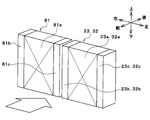
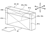
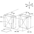
- FIGS. 3 to 5 show examples of the arrangement of the high temperature side radiator 23, the low temperature side radiator 32, and the outdoor heat exchanger 81.
- FIG. 3 to FIG. 5 the up, down, front, back, left, and right arrows indicate the directions of the vehicle.
- the high temperature side radiator 23 and the low temperature side radiator 32 are illustrated integrally.
- the high temperature side radiator 23, the low temperature side radiator 32, and the outdoor heat exchanger 81 are arranged side by side in the vehicle left-right direction.
- the positions of the high-temperature side radiator 23, the low-temperature side radiator 32, and the outdoor heat exchanger 81 in the vertical and longitudinal directions of the vehicle are the same.
- the high temperature side radiator 23, the low temperature side radiator 32, and the outdoor heat exchanger 81 may be arranged side by side in the vehicle vertical direction.
- the high temperature side radiator 23, the low temperature side radiator 32, and the outdoor heat exchanger 81 may be displaced in the longitudinal direction of the vehicle.
- the high temperature side radiator 23, the low temperature side radiator 32, and the outdoor heat exchanger 81 are configured by so-called tank and tube type heat exchangers.
- the outdoor heat exchanger 81 includes an outdoor heat exchange unit 81a and a pair of outdoor tanks 81b and 81c.
- the outdoor heat exchange unit 81 a is a refrigerant outside air heat exchange unit that exchanges heat between the refrigerant and the outside air in the outdoor heat exchanger 81.
- the outdoor heat exchange unit 81a has a plurality of tubes and a plurality of fins.
- the plurality of tubes are refrigerant tubes through which the refrigerant flows.
- the tube is formed of a metal (in the present embodiment, an aluminum alloy) which is excellent in heat conductivity.
- a plurality of tubes are stacked and arranged at regular intervals. Thus, an air passage through which air flows is formed between the adjacent tubes.
- the fins are disposed in an air passage formed between adjacent tubes.
- the fins are heat exchange promoting members that promote heat exchange between the refrigerant and the air.
- the fin is a corrugated fin formed by bending a thin plate made of the same material as the tube into a wave shape.
- the pair of outdoor tanks 81b and 81c are connected to both ends of the plurality of tubes of the outdoor heat exchange section 81a.
- the pair of outdoor tanks 81b and 81c are refrigerant tanks that collect or distribute the refrigerant to a plurality of tubes.
- the outdoor tanks 81b and 81c are formed of the same material as the tube.
- the high temperature side radiator 23 has a high temperature side heat exchange part 23a and a pair of high temperature side tanks 23b and 23c.
- the high temperature side heat exchange unit 23 a is a refrigerant outside air heat exchange unit in the high temperature side radiator 23 that exchanges heat between the cooling water and the air.
- the high temperature side heat exchange unit 23a has a plurality of tubes and a plurality of fins.
- the plurality of tubes are refrigerant tubes for circulating the cooling water.
- the tube is formed of a metal (in the present embodiment, an aluminum alloy) which is excellent in heat conductivity.
- a plurality of tubes are stacked and arranged at regular intervals. Thus, an air passage through which air flows is formed between the adjacent tubes.
- the fins are disposed in an air passage formed between adjacent tubes.
- the fins are heat exchange promoting members that promote heat exchange between the cooling water and the air.
- the fin is a corrugated fin formed by bending a thin plate made of the same material as the tube into a wave shape.
- the pair of high temperature side tanks 23b and 23c are connected to both ends of the plurality of tubes of the high temperature side heat exchange unit 23a.
- the pair of high temperature side tanks 23b and 23c is a refrigerant tank that collects or distributes the refrigerant to a plurality of tubes.
- the high temperature side tanks 23b and 23c are formed of the same material as the tube.
- the low temperature side radiator 32 has a low temperature side heat exchange section 32a and a pair of low temperature side tanks 32b and 32c.
- the low temperature side heat exchange unit 32 a is a low temperature heat medium external air heat exchange unit in the low temperature side radiator 32 that exchanges heat between the cooling water and the air.
- the low temperature side heat exchange unit 32a has a plurality of tubes and a plurality of fins.
- the plurality of tubes are refrigerant tubes for circulating the cooling water.
- the tube is formed of a metal (in the present embodiment, an aluminum alloy) which is excellent in heat conductivity.
- a plurality of tubes are stacked and arranged at regular intervals. Thus, an air passage through which air flows is formed between the adjacent tubes.
- the fins are disposed in an air passage formed between adjacent tubes.
- the fins are heat exchange promoting members that promote heat exchange between the cooling water and the air.
- the fin is a corrugated fin formed by bending a thin plate made of the same material as the tube into a wave shape.
- the pair of low temperature side tanks 32b and 32c are connected to both ends of the plurality of tubes of the low temperature side heat exchange unit 32a.
- the pair of low temperature side tanks 32b and 32c is a refrigerant tank that collects or distributes the refrigerant to a plurality of tubes.
- the low temperature side tanks 32b and 32c are formed of the same material as the tube.
- At least one of the outdoor heat exchange portion 81 a and the low temperature side heat exchange portion 32 a has a portion that does not overlap with the other heat exchange portion in the flow direction of the outside air.
- at least one of the outdoor heat exchange portion 81a and the low temperature side heat exchange portion 32a has a portion that does not overlap with the other heat exchange portion when viewed from the flow direction of the outside air.
- the battery 33, the inverter 35, the charger 36, and the motor generator 37 shown in FIGS. 1 and 2 are in-vehicle devices mounted in a vehicle, and are heat generating devices that generate heat as they operate.
- the battery 33, the inverter 35, the charger 36 and the motor generator 37 dissipate the waste heat generated as the operation is performed to the cooling water of the low temperature cooling water circuit 30.
- the battery 33, the inverter 35, the charger 36 and the motor generator 37 supply heat to the cooling water of the low temperature cooling water circuit 30.
- the inverter 35 is a power conversion unit that converts DC power supplied from the battery 33 into AC power and outputs the AC power to the motor generator 37.
- the charger 36 is a charger for charging the battery 33.
- the motor generator 37 generates driving power for traveling using the electric power output from the inverter 35, and generates regenerative electric power during deceleration or downhill.
- the low temperature side reserve tank 40 is a cooling water storage unit that stores excess cooling water. By storing the excess cooling water in the low temperature side reserve tank 40, it is possible to suppress a decrease in the amount of cooling water circulating in each flow path.
- the low temperature side reserve tank 40 is a closed reserve tank or an open air reserve tank.
- the closed reserve tank is a reserve tank in which the pressure at the liquid surface of the stored cooling water is a predetermined pressure.
- the open air type reserve tank is a reserve tank in which the pressure at the liquid surface of the stored cooling water is atmospheric pressure.
- the first three-way valve 38, the first low temperature side pump 31, the cooling water cooling evaporator 17, and the low temperature side reserve tank 40 are disposed in the low temperature side main flow passage 30a.
- the low temperature side main flow passage 30a is a flow passage through which the low temperature side cooling water flows.
- the low temperature side radiator 32 is disposed in the low temperature side radiator flow passage 30b.
- the low temperature side radiator flow passage 30b is a flow passage through which the low temperature side cooling water flows.
- the low temperature side main flow passage 30a and the low temperature side radiator flow passage 30b form a cooling water circuit in which low temperature side cooling water circulates.
- the battery 33 is disposed in the battery flow passage 30c.
- the battery flow passage 30c is connected to the low temperature side main flow passage 30a.
- the low temperature side main flow passage 30a and the battery flow passage 30c form a cooling water circuit in which the low temperature side cooling water is circulated.
- a first three-way valve 38 is disposed at the connection between the low temperature side main flow passage 30a and the battery flow passage 30c.
- the first three-way valve 38 switches between a state in which the cooling water in the low temperature side main flow path 30 a circulates in the battery flow path 30 c and a state in which the cooling water does not circulate.
- the operation of the first three-way valve 38 is controlled by the controller 60.
- the second low temperature side pump 34, the inverter 35, the charger 36, and the motor generator 37 are disposed in the device flow path 30d.
- the low temperature side main flow passage 30a and the device flow passage 30d form a cooling water circuit in which the low temperature side cooling water circulates.
- a bypass flow passage 30e is connected to the device flow passage 30d.
- the device flow path 30 d and the bypass flow path 30 e form a cooling water circuit in which the low temperature side cooling water circulates.
- a second three-way valve 39 is disposed at the connection between the device flow path 30d and the bypass flow path 30e.
- the second three-way valve 39 switches between a state in which the cooling water in the low temperature side main flow passage 30a circulates in the device flow passage 30d and a state in which the cooling water in the device flow passage 30d circulates in the bypass flow passage 30e. Switch between non-circulating state.
- the operation of the second three-way valve 39 is controlled by the controller 60.
- the first three-way valve 38 and the second three-way valve 39 are low temperature switching units that switch the flow of the cooling water in the low temperature cooling water circuit 30.
- the air cooling evaporator 14 and the heater core 22 are housed in a casing 51 (hereinafter referred to as an air conditioning casing) of the indoor air conditioning unit 50 shown in FIG. 1.
- the indoor air conditioning unit 50 is disposed inside the instrument panel (not shown) at the front of the passenger compartment.
- the air conditioning casing 51 is an air passage forming member that forms an air passage.
- the heater core 22 is disposed on the air flow downstream side of the air cooling evaporator 14 in the air passage in the air conditioning casing 51.
- an inside / outside air switching box 52 and an indoor blower 53 are disposed in the air conditioning casing 51.
- the inside / outside air switching box 52 is an inside / outside air switching unit that switches and introduces inside air and outside air to the air passage in the air conditioning casing 51.
- the indoor blower 53 sucks and blows the inside air and the outside air introduced into the air passage in the air conditioning casing 51 through the inside / outside air switching box 52.
- An air mix door 54 is disposed between the air cooling evaporator 14 and the heater core 22 in the air passage in the air conditioning casing 51.
- the air mix door 54 adjusts the volume ratio of the cold air flowing into the heater core 22 and the cold air flowing through the cold air bypass passage 55 among the cold air having passed through the air cooling evaporator 14.
- the air mix door 54 is an air heating amount adjustment unit that adjusts the heating amount of air in the heater core 22.
- the cold air bypass passage 55 is an air passage through which the cold air that has passed through the air cooling evaporator 14 flows to bypass the heater core 22.
- the air mix door 54 is a rotary door having a rotary shaft rotatably supported on the air conditioning casing 51 and a door base portion coupled to the rotary shaft. By adjusting the position of the air mix door 54, the temperature of the conditioned air blown out from the air conditioning casing 51 into the vehicle compartment can be adjusted to a desired temperature.
- the rotation shaft of the air mix door 54 is driven by a servomotor.
- the operation of the servomotor is controlled by the controller 60.
- the air mix door 54 may be a slide door that slides in a direction substantially orthogonal to the air flow.
- the sliding door may be a plate-like door formed of a rigid body. It may be a film door formed of a flexible film material.
- the conditioned air whose temperature has been adjusted by the air mix door 54 is blown out from the air outlet 56 formed in the air conditioning casing 51 into the vehicle compartment.
- the control device 60 shown in FIG. 6 is composed of a known microcomputer including a CPU, a ROM, a RAM and the like, and peripheral circuits thereof.
- the control device 60 performs various operations and processing based on the control program stored in the ROM.
- Various control target devices are connected to the output side of the control device 60.
- the control device 60 is a control unit that controls the operation of various control target devices.
- the control target devices controlled by the control device 60 include the compressor 11, the first expansion valve 80, the second expansion valve 13, the third expansion valve 16, the outdoor blower 41, the high temperature side pump 21, the two-way valve 24, the first The low temperature side pump 31, the second low temperature side pump 34, the first three-way valve 38, the second three-way valve 39, and the like.
- the software and hardware for controlling the electric motor of the compressor 11 in the control device 60 are a refrigerant discharge capacity control unit.
- the software and hardware which control the 2nd expansion valve 13 among control devices 60 are the 1st iris diaphragm control parts.
- the software and hardware for controlling the third expansion valve 16 in the control device 60 is a second throttle control unit.
- Software and hardware for controlling the outdoor blower 41 in the control device 60 are an outdoor air blowing capacity control unit.
- Software and hardware for controlling the high temperature side pump 21 in the control device 60 is a high temperature heat medium flow rate control unit.
- the software and hardware for controlling the two-way valve 24 in the controller 60 is a two-way valve control unit.
- the software and hardware for controlling the first low temperature side pump 31 and the second low temperature side pump 34 in the control device 60 is a low temperature heat medium flow rate control unit.
- the software and hardware for controlling the first three-way valve 38 in the controller 60 is a first three-way valve control unit.
- Software and hardware for controlling the second three-way valve 39 in the controller 60 is a second three-way valve control unit.
- Various control sensor groups such as a temperature sensor 68 and a window surface humidity sensor 69 are connected.
- the inside air temperature sensor 61 detects a temperature Tr in the passenger compartment.
- the outside air temperature sensor 62 detects the outside air temperature Tam.
- the solar radiation amount sensor 63 detects the solar radiation amount Ts in the vehicle compartment.
- the evaporator temperature sensor 64 is a temperature detection unit that detects the temperature of the cooling water cooling evaporator 17.
- the evaporator temperature sensor 64 is, for example, a fin thermistor that detects the temperature of the heat exchange fin of the cooling water cooling evaporator 17, or a refrigerant temperature sensor that detects the temperature of the refrigerant flowing through the cooling water cooling evaporator 17. .
- the heater core temperature sensor 65 is a temperature detection unit that detects the temperature of the heater core 22.
- the heater core temperature sensor 65 is, for example, a fin thermistor that detects the temperature of heat exchange fins of the heater core 22, a refrigerant temperature sensor that detects the temperature of cooling water flowing through the heater core 22, and air that detects the temperature of air flowing out of the heater core 22. It is a temperature sensor or the like.
- the refrigerant pressure sensor 66 is a refrigerant pressure detection unit that detects the pressure of the refrigerant discharged from the compressor 11. Instead of the refrigerant pressure sensor 66, a refrigerant temperature sensor may be connected to the input side of the control device 60.
- the refrigerant temperature sensor is a refrigerant pressure detection unit that detects the temperature of the refrigerant discharged from the compressor 11.
- the controller 60 may estimate the pressure of the refrigerant based on the temperature of the refrigerant.
- the high temperature coolant temperature sensor 67 is a temperature detection unit that detects the temperature of the coolant in the high temperature coolant circuit 20.
- the high temperature coolant temperature sensor 67 detects the temperature of the coolant of the condenser 12.
- the low temperature coolant temperature sensor 68 is a temperature detection unit that detects the temperature of the coolant in the low temperature coolant circuit 30. For example, the low temperature coolant temperature sensor 68 detects the temperature of the coolant of the coolant cooling evaporator 17.
- the window surface humidity sensor 69 is configured of a near window humidity sensor, a near window air temperature sensor, and a window surface temperature sensor.
- the near-window humidity sensor detects the relative humidity (hereinafter referred to as the near-window relative humidity) of the air in the vehicle room near the windshield in the vehicle room.
- the near-window air temperature sensor detects the temperature of the air in the passenger compartment near the windshield.
- the window surface temperature sensor detects the surface temperature of the windshield.
- Various operation switches (not shown) are connected to the input side of the control device 60.
- Various operation switches are provided on the operation panel 70 and operated by the occupant.
- the operation panel 70 is disposed near the dashboard in the front of the vehicle compartment. Operation signals from various operation switches are input to the control device 60.
- the various operation switches are an air conditioner switch, a temperature setting switch, and the like.
- the air conditioner switch sets whether to cool the air in the indoor air conditioning unit 50 or not.
- the temperature setting switch sets the set temperature of the vehicle interior.
- the control device 60 switches the operation mode to either the cooling mode shown in FIGS. 7 to 8 or the heating mode shown in FIGS. 9 to 10 based on the target blowing temperature TAO or the like.
- the target blowing temperature TAO is a target temperature of the blowing air blown out into the vehicle compartment.
- Control device 60 calculates target blowout temperature TAO based on the following formula.
- TAO Kset ⁇ Tset-Kr ⁇ Tr-Kam ⁇ Tam-Ks ⁇ Ts + C
- Tset is a vehicle interior set temperature set by the temperature setting switch of the operation panel 70
- Tr is the inside air temperature detected by the inside air temperature sensor 61
- Tam is the outside air temperature detected by the outside air temperature sensor 62
- Ts is It is a solar radiation amount detected by the solar radiation amount sensor 63.
- Kset, Kr, Kam, and Ks are control gains
- C is a correction constant.
- the control device 60 switches to the dehumidifying and heating mode when it is determined that the window of the vehicle may become cloudy in the heating mode. For example, in the heating mode, the control device 60 calculates relative humidity RHW (hereinafter referred to as window surface relative humidity) of the vehicle interior side surface based on the detection value of the window surface humidity sensor 69, Based on the relative humidity RHW, it is determined whether the window of the vehicle may become cloudy.
- RHW relative humidity
- the window surface relative humidity RHW is an index that indicates the possibility of the windshield becoming cloudy. Specifically, the larger the value of the window surface relative humidity RHW, the higher the possibility of the windshield being clouded.
- the control device 60 determines operation states (control signals to be output to various control devices) of various control devices connected to the control device 60 based on the target blowout temperature TAO, detection signals of the sensor group, and the like.
- the degree of superheat of the refrigerant flowing into the compressor 11 approaches a target degree of superheat determined in advance so that the coefficient of performance (so-called COP) of the cycle approaches the maximum value. To be determined.
- the air mix door 54 With regard to the control signal output to the servo motor of the air mix door 54, the air mix door 54 is positioned at the solid line position in FIG. 1 to close the air passage of the heater core 22 and of the air passing through the air cooling evaporator 14. The total flow rate is determined to flow around the air passage of the heater core 22.
- the compressor 11 and the high temperature side pump 21 are operated.
- the two-way valve 24 opens the radiator flow passage 20b.
- the cooling water of the high temperature cooling water circuit 20 circulates through the high temperature side radiator 23 and is radiated from the cooling water by the radiator 23 to the outside air.
- the cooling water of the high temperature cooling water circuit 20 also circulates through the heater core 22.
- the air mixing door 54 blocks the air passage of the heater core 22, the heater core 22 hardly dissipates heat from the cooling water to the air. I can not do it.
- the refrigerant flows as indicated by the broken line arrow in FIG. 1, and the state of the refrigerant circulating in the cycle changes as follows.
- the high pressure refrigerant discharged from the compressor 11 flows into the condenser 12.
- the refrigerant flowing into the condenser 12 releases heat to the cooling water of the high temperature cooling water circuit 20.
- the refrigerant is cooled and condensed in the condenser 12.
- the refrigerant flowing out of the condenser 12 flows into the first expansion valve 80. Since the first expansion valve 80 is fully open, the refrigerant is not decompressed and expanded in the first expansion valve 80.
- the refrigerant flowing out of the first expansion valve 80 flows into the outdoor heat exchanger 81, and radiates heat to the outside air. Thereby, the refrigerant is cooled and condensed also in the first expansion valve 80.
- the refrigerant flowing out of the first expansion valve 80 flows into the second expansion valve 13 and is decompressed and expanded in the second expansion valve 13 until it becomes a low pressure refrigerant.
- the low-pressure refrigerant reduced in pressure by the second expansion valve 13 flows into the air cooling evaporator 14, absorbs heat from the air blown into the vehicle compartment, and is evaporated. Thus, the air blown into the vehicle compartment is cooled.
- the low-pressure refrigerant can absorb heat from the air by the air cooling evaporator 14 to blow out the cooled air into the vehicle compartment. Thereby, cooling of the vehicle interior can be realized.
- the third expansion valve 16 is put into a throttled state and the first low temperature side pump 31 is operated.
- the refrigerant flowing out of the condenser 12 flows into the third expansion valve 16 and is decompressed and expanded by the third expansion valve 16 until it becomes a low pressure refrigerant.
- the low pressure refrigerant decompressed by the third expansion valve 16 flows into the cooling water cooling evaporator 17, absorbs heat from the cooling water of the low temperature cooling water circuit 30, and is evaporated. Thereby, the cooling water of the low temperature cooling water circuit 30 is cooled.
- the first three-way valve 38 causes the cooling water in the low temperature side main flow passage 30a to circulate in the battery flow passage 30c.
- the cooling water of the low temperature cooling water circuit 30 circulates in the battery 33 and the battery 33 is cooled.
- the second three-way valve 39 causes the cooling water in the low temperature side main flow passage 30a to circulate in the device flow passage 30d.
- the cooling water of low temperature cooling water circuit 30 circulates through inverter 35, charger 36 and motor generator 37 to cause inverter 35, charger 36 and motor generator 37. Is cooled.
- Heating mode In the heating mode, the controller 60 brings the first expansion valve 80 into the throttling state, brings the second expansion valve 13 into the fully closed state, and brings the third expansion valve 16 into the throttling state.
- the control device 60 determines operation states (control signals to be output to various control devices) of various control devices connected to the control device 60 based on the target blowout temperature TAO, detection signals of the sensor group, and the like.
- the control signal output to the first expansion valve 80 is determined such that the temperature of the refrigerant flowing into the outdoor heat exchanger 81 is equal to or lower than the outside air temperature.
- the control signal output to the third expansion valve 16 is determined so that the degree of superheat of the refrigerant flowing into the compressor 11 approaches a predetermined target degree of superheat.
- the target degree of superheat is set so that the coefficient of performance (so-called COP) of the cycle approaches the maximum value.
- the air mix door 54 With regard to the control signal output to the servo motor of the air mix door 54, the air mix door 54 is located at the broken line position in FIG. 1 to fully open the air passage of the heater core 22 and of the air passing through the air cooling evaporator 14. The total flow rate is determined to pass through the air passage of the heater core 22.
- the compressor 11, the high temperature side pump 21, and the first low temperature side pump 31 are operated.
- the two-way valve 24 closes the radiator flow passage 20b.
- the coolant of high temperature coolant circuit 20 circulates through heater core 22 and is dissipated from the coolant by heater core 22 into the air blown into the vehicle compartment. Be done.
- the first three-way valve 38 closes the battery flow passage 30c
- the second three-way valve 39 closes the device flow passage 30d and the bypass flow passage 30e.
- the cooling water of the low temperature cooling water circuit 30 circulates through the low temperature side radiator 32.
- the refrigerant flows as indicated by solid arrows in FIG. 1, and the state of the refrigerant circulating in the cycle changes as follows.
- the high pressure refrigerant discharged from the compressor 11 flows into the condenser 12, exchanges heat with the cooling water of the high temperature cooling water circuit 20, and radiates heat. Thereby, the cooling water of the high temperature cooling water circuit 20 is heated.
- the refrigerant flowing out of the condenser 12 flows into the first expansion valve 80 and is depressurized so as to be equal to or lower than the outside air temperature. Then, the refrigerant decompressed by the first expansion valve 80 flows into the outdoor heat exchanger 81 and hardly exchanges heat with the outside air or absorbs heat from the outside air.
- the refrigerant flowing out of the first expansion valve 80 flows into the third expansion valve 16 and is decompressed until it becomes a low pressure refrigerant. Then, the low pressure refrigerant decompressed by the third expansion valve 16 flows into the cooling water cooling evaporator 17, absorbs heat from the cooling water of the low temperature cooling water circuit 30, and evaporates.
- the heat of the high pressure refrigerant discharged from the compressor 11 is dissipated to the cooling water of the high temperature cooling water circuit 20 by the condenser 12 and the heat of the cooling water of the high temperature cooling water circuit 20 is The heat can be released to the air by the heater core 22 and the air heated by the heater core 22 can be blown out into the vehicle interior. Thereby, heating of the vehicle interior can be realized.
- the cooling water of the low temperature cooling water circuit 30 circulates through the low temperature side radiator 32, heat is absorbed from the outside air into the cooling water of the low temperature cooling water circuit 30, and the cooling water of the low temperature cooling water circuit 30 is used in the cooling water cooling evaporator 17.
- the low pressure refrigerant can absorb heat. Therefore, the heat of the outside air can be used to heat the vehicle interior.
- the cooling water of the low temperature cooling water circuit 30 is also circulated to the battery 33, the inverter 35, the charger 36 and the motor generator 37. Absorbing waste heat of the inverter 35, the charger 36 and the motor generator 37 into the cooling water of the low temperature cooling water circuit 30, and absorbing heat from the cooling water of the low temperature cooling water circuit 30 into the low pressure refrigerant in the cooling water cooling evaporator 17. Can.
- waste heat of battery 33, inverter 35, charger 36 and motor generator 37 can be used to heat the vehicle interior. Further, waste heat of the battery 33, the inverter 35, the charger 36 and the motor generator 37 can be used for defrosting of the low temperature side radiator 32.
- Waste heat can be used to heat and defrost the vehicle interior.
- the high temperature side radiator 23 and the low temperature side radiator 32 are connected so as to be able to transfer heat to each other by the common fin F1, the heat of the cooling water of the high temperature cooling water circuit 20 is transmitted from the high temperature side radiator 23 to the low temperature side radiator 32.
- the temperature of the low temperature side radiator 32 is increased, and the frost adhering to the surface of the low temperature side radiator 32 can be melted.
- the control device 60 sets the first expansion valve 80 in the squeezed state, sets the second expansion valve 13 in the fully closed state, and sets the third expansion valve 16 in the fully closed state.
- the control device 60 determines operation states (control signals to be output to various control devices) of various control devices connected to the control device 60 based on the target blowout temperature TAO, detection signals of the sensor group, and the like.
- the control signal output to the first expansion valve 80 is determined such that the temperature of the refrigerant flowing into the outdoor heat exchanger 81 is lower than the outside air temperature.
- the control signal output to the third expansion valve 16 is determined so that the degree of superheat of the refrigerant flowing into the third expansion valve 16 approaches a predetermined target degree of superheat.
- the target degree of superheat is set so that the coefficient of performance (so-called COP) of the cycle approaches the maximum value.
- the air mix door 54 With regard to the control signal output to the servo motor of the air mix door 54, the air mix door 54 fully opens the air passage of the heater core 22, and the total flow rate of air passing through the air cooling evaporator 14 is the air passage of the heater core 22. It is decided to pass.
- the compressor 11, the high temperature side pump 21, and the first low temperature side pump 31 are operated.
- the two-way valve 24 closes the radiator flow passage 20b.
- the coolant of high temperature coolant circuit 20 circulates through heater core 22 and is dissipated from the coolant by heater core 22 into the air blown into the vehicle compartment. Be done.
- the refrigerant flows as indicated by the broken line arrow in FIG. 1, and the state of the refrigerant circulating in the cycle changes as follows.
- the high pressure refrigerant discharged from the compressor 11 flows into the condenser 12, exchanges heat with the cooling water of the high temperature cooling water circuit 20, and radiates heat. Thereby, the cooling water of the high temperature cooling water circuit 20 is heated.
- the refrigerant flowing out of the condenser 12 flows into the first expansion valve 80 and is depressurized so as to be lower than the outside air temperature. Then, the refrigerant decompressed by the first expansion valve 80 flows into the outdoor heat exchanger 81 and absorbs heat from the outside air.
- the refrigerant flowing out of the first expansion valve 80 flows into the second expansion valve 13 and is decompressed until it becomes a low pressure refrigerant. Then, the low pressure refrigerant reduced in pressure by the second expansion valve 13 flows into the air cooling evaporator 14 and absorbs heat from the air blown into the vehicle compartment to evaporate. Thus, the air blown into the vehicle compartment is cooled and dehumidified. Then, the refrigerant flowing out of the air cooling evaporator 14 flows to the suction side of the compressor 11 and is compressed again by the compressor 11.
- the heat of the high pressure refrigerant discharged from the compressor 11 is dissipated to the cooling water of the high temperature cooling water circuit 20 by the condenser 12 and the heat of the cooling water of the high temperature cooling water circuit 20 The heat is released to the air by the heater core 22.
- the low pressure refrigerant decompressed by the third expansion valve 16 is absorbed from the air blown into the vehicle compartment by the air cooling evaporator 14, and the air cooled and dehumidified by the air cooling evaporator 14 is a heater core. It can heat at 22 and can blow out to a vehicle interior. Thereby, dehumidification heating of a vehicle interior can be realized.
- the refrigerant expanded in pressure by the first expansion valve 80 flows into the outdoor heat exchanger 81 to absorb heat from the outside air by setting the first expansion valve 80 in the squeezed state. Therefore, the heat of the outside air can be used to heat the vehicle interior.
- the low pressure refrigerant reduced in pressure by the third expansion valve 16 flows into the cooling water cooling evaporator 17 by bringing the third expansion valve 16 into a throttling state, and cooling of the low temperature cooling water circuit 30 It absorbs heat from water and evaporates.
- the cooling water of the low temperature cooling water circuit 30 is circulated in the low temperature side radiator 32 to absorb heat from the outside air to the cooling water of the low temperature cooling water circuit 30.
- the low-pressure refrigerant can absorb heat from the cooling water of the low-temperature cooling water circuit 30 in the cooling water cooling evaporator 17. Therefore, the heat of the outside air can be used to heat the vehicle interior.
- the cooling water cooled by the cooling water cooling evaporator 17 is also circulated to the battery 33, the inverter 35, the charger 36 and the motor generator 37.
- the waste heat of the battery 33, the inverter 35, the charger 36 and the motor generator 37 is absorbed by the cooling water of the low temperature cooling water circuit 30, and the cooling water of the low temperature cooling water circuit 30 is changed to a low pressure refrigerant in the cooling water cooling evaporator 17. It can be absorbed heat. Therefore, the waste heat of battery 33, inverter 35, charger 36 and motor generator 37 can be used to heat the vehicle interior.
- the refrigerant flow to the evaporator 14 for air cooling and the evaporator 17 for thermal cooling water cooling, and the cooling water flow in the high temperature cooling water circuit 20 and the low temperature cooling water circuit 30
- proper cooling, heating and dehumidifying heating can be performed in the vehicle interior, and thus comfortable air conditioning of the vehicle interior can be realized.
- the controller 60 controls the second three-way valve 39 so that the cooling water of the low temperature cooling water circuit 30 circulates between the low temperature side radiator 32 and the inverter 35, the charger 36 and the motor generator 37 as shown in FIG.
- the waste heat of inverter 35, charger 36 and motor generator 37 can be released to the outside air to cool inverter 35, charger 36 and motor generator 37.
- the first expansion valve 80 can be switched between a state in which the refrigerant dissipates heat to the outside air by the outdoor heat exchanger 81 and a state in which the refrigerant absorbs heat from the outside air by the outdoor heat exchanger 81. Then, when the air is cooled by the air cooling evaporator 14 and the air is heated by the heater core 22, the third expansion valve 16 causes the coolant to flow to the cooling water cooling evaporator 17.
- the refrigerant cools the air in the air cooling evaporator 14 and the refrigerant dissipates the outside air in the outdoor heat exchanger 81, whereby the cooling mode can be realized.
- the refrigerant absorbs heat from the outside air in the outdoor heat exchanger 81, and the heat of the refrigerant is used in the condenser 12 and the heater core 22 to heat the air, whereby the heating mode can be realized.
- the refrigerant cools the air in the air cooling evaporator 14 and heats the air in the condenser 12 and the heater core 22 using the heat of the refrigerant to realize the dehumidifying and heating mode.
- the cooling water cooling evaporator 17 can absorb the heat from the heat medium. Therefore, since it is not necessary to frequently switch the high and low pressure of the outdoor heat exchanger 81 at the time of the dehumidifying and heating mode, the operation and control can be simplified.
- the first expansion valve 80 can be switched between a state in which the refrigerant dissipates heat to the outside air by the outdoor heat exchanger 81 and a state in which the refrigerant absorbs heat from the outside air by the outdoor heat exchanger 81.
- the outdoor heat exchanger 81 has an outdoor heat exchange unit 81a that exchanges heat between the refrigerant and the outside air.
- the low temperature side radiator 32 has a low temperature side heat exchange section 32 a that exchanges heat between the cooling water and the outside air.
- At least one heat exchange portion of the outdoor heat exchange portion 81a and the low temperature side heat exchange portion 32a has a portion that does not overlap in the flow direction of the other heat exchange portion and the outside air.
- the third expansion valve 16 causes the refrigerant to flow to the cooling water cooling evaporator 17 when the refrigerant absorbs heat from the outside air in the outdoor heat exchanger 81 and the air is heated in the heater core 22.
- the refrigerant cools the air in the air cooling evaporator 14 and the refrigerant dissipates the outside air in the outdoor heat exchanger 81, whereby the cooling mode can be realized.
- the refrigerant absorbs heat from the outside air in the outdoor heat exchanger 81, and the heat of the refrigerant is used in the condenser 12 and the heater core 22 to heat the air, whereby the heating mode can be realized.
- the cooling water cooling evaporator 17 can absorb heat from the cooling water.
- At least one of the outdoor heat exchange portion 81a and the low temperature side heat exchange portion 32a has a portion that does not overlap in the flow direction of the other heat exchange portion and the outside air, so the outdoor heat exchange portion 81a
- the heat absorption area can be increased by increasing the heat exchange area of the low temperature side heat exchange section 32a. Therefore, the heating performance can be improved.
- the cooling water cooled by the cooling water cooling evaporator 17 circulates through the low temperature cooling water circuit 30, the cooling water of the low temperature cooling water circuit 30 is the heat of the outside air also in the piping portion of the low temperature cooling water circuit 30 and the like. Can absorb heat.
- the compressor 11 when the air is cooled by the air cooling evaporator 14 and the air is heated by the heater core 22, the compressor 11, the heater core 22, the first expansion valve 80, the outdoor heat exchanger 81, the second expansion
- the refrigerant circulates in the order of the valve 13, the evaporator 14 for air cooling, and the compressor 11.
- the refrigerant cools the air in the air cooling evaporator 14, and the heat of the refrigerant is used in the condenser 12 and the heater core 22 to heat the air, whereby dehumidifying and heating can be realized.
- the air cooling evaporator 14 and the cooling water cooling evaporator 17 are arranged in parallel with each other in the flow of the refrigerant. Thereby, the temperature zone of the evaporator 14 for air cooling and the evaporator 17 for cooling water cooling can be adjusted easily.
- the pressure adjustment unit 25 makes the outlet-side refrigerant pressure of the air-cooling evaporator 14 equal to or higher than the outlet-side refrigerant pressure of the coolant-cooling evaporator 17.
- dehumidifying and heating can be performed in a wide temperature range in the low outside air temperature zone.
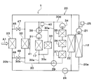
- the second expansion valve 13 and the second expansion valve 15 are electrically variable throttle mechanisms with a fully closed function, but in the present embodiment, as shown in FIG.
- the second expansion valve 15 is a mechanical thermal expansion valve
- the first on-off valve 18 is disposed in the first parallel refrigerant flow passage 10b
- the second on-off valve 19 is disposed in the second parallel refrigerant flow passage 10c. ing.
- the mechanical expansion valve is a thermal expansion valve that has a temperature sensing unit and drives a valve body by a mechanical mechanism such as a diaphragm.
- the first on-off valve 18 is an electromagnetic valve that opens and closes the first parallel refrigerant flow passage 10 b.
- the second on-off valve 19 is an electromagnetic valve that opens and closes the second parallel refrigerant flow passage 10c. The operation of the first on-off valve 18 and the second on-off valve 19 is controlled by a control signal output from the controller 60.
- the constant pressure valve 15 is a mechanical variable throttle mechanism, but in the present embodiment, it is an electric variable throttle mechanism, and the operation of the constant pressure valve 15 is controlled from the control device 60 Controlled by the signal.
- the high temperature side radiator 23 and the low temperature side radiator 32 are connected so as to be able to transfer heat to each other by the common fin F1, but in the present embodiment, as shown in FIG.
- the side radiators 32 are capable of heat transfer to each other via the cooling water.
- the radiator flow passage 20 b and the low temperature side radiator flow passage 30 b are in communication by two cooling water flow passages 45 and 46.
- the two cooling water flow paths 45, 46 connect the high temperature side radiator 23 and the low temperature side radiator 32 on the inlet side and the outlet side of the cooling water.
- An on-off valve 47 is disposed in one cooling water flow path 45.
- An open / close valve 48 is disposed in the other cooling water passage 46.
- One on-off valve 47 is an electromagnetic valve that opens and closes one cooling water passage 45.
- the other on-off valve 48 is a solenoid valve that opens and closes the other cooling water passage 46. The operation of the on-off valves 47 and 48 is controlled by the controller 60.
- the controller 60 controls the on-off valves 47 and 48 to close the cooling water channels 45 and 46 under normal conditions.
- the control device 60 controls the on-off valves 47 and 48 to open the cooling water channels 45 and 46 when the vehicle stops after the heating mode is performed. Thereby, the cooling water of the high temperature cooling water circuit 20 is introduced to the low temperature side radiator 32, so the temperature of the low temperature side radiator 32 is raised by utilizing the heat remaining in the cooling water of the high temperature cooling water circuit 20. The frost adhering to the surface of the side radiator 32 can be melted.
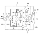
- an engine 26 and an engine radiator 27 are disposed in the high temperature coolant circuit 20.
- the engine radiator 27 is a heat exchanger for radiating heat which exchanges heat between the high temperature cooling water after cooling the engine 26 and the outside air to radiate the heat from the cooling water of the high temperature cooling water circuit 20 to the outside air.
- the heater core 22, the high temperature side radiator 23, the engine 26, and the engine radiator 27 are arranged in parallel to each other in the flow of the cooling water of the high temperature cooling water circuit 20.
- waste heat of the engine 26 can be used for heating.
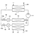
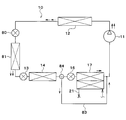
- an indoor condenser 82 is disposed instead of the condenser 12 and the heater core 22 of the above embodiment.
- the indoor condenser 82 is disposed in the refrigeration cycle apparatus 10 instead of the condenser 12 of the above embodiment. Specifically, the indoor condenser 82 condenses the high-pressure side refrigerant by exchanging heat between the high-pressure side refrigerant discharged from the compressor 11 and the air blown into the vehicle interior, and the air blown into the vehicle interior Is an air heating unit that heats
- the indoor condenser 82 is disposed in the air passage in the air conditioning casing 51 in place of the heater core 22 of the above embodiment. Specifically, the indoor condenser 82 is disposed on the air flow downstream side of the air cooling evaporator 14 in the air passage in the air conditioning casing 51.
- the air cooling evaporator 14 and the cooling water cooling evaporator 17 are arranged in parallel with each other in the refrigerant flow, but in the present embodiment, as shown in FIG. 14 and cooling water cooling evaporators 17 are arranged in series with each other in the refrigerant flow.
- the second expansion valve 13, the air cooling evaporator 14, the third expansion valve 16, and the cooling water cooling evaporator 17 are arranged in this order.
- the refrigeration cycle apparatus 10 has a bypass flow passage 83 and a bypass three-way valve 84.
- the bypass flow path 83 is a refrigerant flow path in which the refrigerant flows by bypassing the third expansion valve 16 and the cooling water cooling evaporator 17.
- the bypass three-way valve 84 bypasses the third expansion valve 16 and the cooling water cooling evaporator 17 when the refrigerant flowing out of the air cooling evaporator 14 flows through the third expansion valve 16 and the cooling water cooling evaporator 17. It is an electromagnetic valve that switches between the flow in the bypass passage 83 and the flow in the bypass flow passage 83. The operation of the bypass three-way valve 84 is controlled by the controller 60.
- the control device 60 In the cooling mode, the control device 60 causes the first expansion valve 80 to be fully open, the second expansion valve 13 to be in the throttling state, and the bypass three-way valve 84 to be in the state where the refrigerant flows in the bypass flow path 83.
- the control device 60 determines operation states (control signals to be output to various control devices) of various control devices connected to the control device 60 based on the target blowout temperature TAO, detection signals of the sensor group, and the like.
- the degree of superheat of the refrigerant flowing into the compressor 11 approaches a target degree of superheat determined in advance so that the coefficient of performance (so-called COP) of the cycle approaches the maximum value. To be determined.
- the air mix door 54 With regard to the control signal output to the servo motor of the air mix door 54, the air mix door 54 is located at the solid line position of FIG. 1 and blocks the air passage of the indoor condenser 82 and passes through the air cooling evaporator 14. The total flow rate of air is determined to flow around the air passage of the indoor condenser 82.
- the compressor 11 In the cooling mode, the compressor 11 is operated. In the refrigeration cycle apparatus 10 in the cooling mode, the refrigerant flows as indicated by the broken line arrow in FIG. 13, and the state of the refrigerant circulating in the cycle changes as follows.
- the high pressure refrigerant discharged from the compressor 11 flows into the indoor condenser 82.
- the indoor condenser 82 since the air mix door 54 blocks the air passage of the indoor condenser 82, the indoor condenser 82 hardly dissipates heat from the high pressure refrigerant to the air.
- the refrigerant flowing out of the condenser 12 flows into the first expansion valve 80. Since the first expansion valve 80 is fully open, the refrigerant is not decompressed and expanded in the first expansion valve 80.
- the refrigerant flowing out of the first expansion valve 80 flows into the outdoor heat exchanger 81, and radiates heat to the outside air. Thus, the refrigerant is cooled and condensed by the first expansion valve 80.
- the refrigerant flowing out of the first expansion valve 80 flows into the second expansion valve 13 and is decompressed and expanded in the second expansion valve 13 until it becomes a low pressure refrigerant.
- the low-pressure refrigerant reduced in pressure by the second expansion valve 13 flows into the air cooling evaporator 14, absorbs heat from the air blown into the vehicle compartment, and is evaporated. Thus, the air blown into the vehicle compartment is cooled.
- the refrigerant flowing out of the air cooling evaporator 14 passes through the bypass flow passage 83, flows to the suction side of the compressor 11, and is compressed again by the compressor 11.
- the low-pressure refrigerant can absorb heat from the air by the air cooling evaporator 14 to blow out the cooled air into the vehicle compartment. Thereby, cooling of the vehicle interior can be realized.
- the control device 60 sets the first expansion valve 80 in the squeezed state, sets the second expansion valve 13 in the squeezed state, the bypass three-way valve 84, and the refrigerant is the third expansion valve 16 and the cooling water cooling evaporator Let 17 flow.
- the third expansion valve 16 is fully closed.
- the control device 60 determines operation states (control signals to be output to various control devices) of various control devices connected to the control device 60 based on the target blowout temperature TAO, detection signals of the sensor group, and the like.
- the control signal output to the first expansion valve 80 is determined such that the temperature of the refrigerant flowing into the outdoor heat exchanger 81 is lower than the outside air temperature.
- the control signal output to the second expansion valve 13 is determined so that the degree of superheat of the refrigerant flowing into the compressor 11 approaches a predetermined target degree of superheat.
- the target degree of superheat is set so that the coefficient of performance (so-called COP) of the cycle approaches the maximum value.
- the air mix door 54 As for the control signal output to the servo motor of the air mix door 54, the air mix door 54 fully opens the air passage of the indoor condenser 82, and the total flow rate of the air passing through the air cooling evaporator 14 is the indoor condenser 82. It is decided to pass through the air passage of the
- the compressor 11 and the first low temperature side pump 31 are operated.
- the refrigerant flows as indicated by solid arrows in FIG. 13, and the state of the refrigerant circulating in the cycle changes as follows.
- the high-pressure refrigerant discharged from the compressor 11 flows into the indoor condenser 82, exchanges heat with the air blown into the vehicle compartment, and radiates heat.
- the air blown into the vehicle compartment is heated.
- the refrigerant flowing out of the indoor condenser 82 flows into the first expansion valve 80 and is depressurized so as to be less than the outside air temperature. Then, the refrigerant decompressed by the first expansion valve 80 flows into the outdoor heat exchanger 81 and absorbs heat from the outside air.
- the refrigerant flowing out of the first expansion valve 80 flows into the second expansion valve 13 and is decompressed until it becomes a low pressure refrigerant. Then, the low pressure refrigerant reduced in pressure by the second expansion valve 13 flows into the air cooling evaporator 14 and absorbs heat from the air blown into the vehicle compartment to evaporate. Thus, the air blown into the vehicle compartment is cooled and dehumidified. Then, the refrigerant flowing out of the air cooling evaporator 14 flows into the third expansion valve 16, and the refrigerant flowing out of the third expansion valve 16 flows into the cooling water cooling evaporator 17, and the low temperature cooling water circuit 30 Absorbs heat from the cooling water and evaporates. The refrigerant flowing out of the cooling water cooling evaporator 17 flows to the suction side of the compressor 11 and is compressed by the compressor 11 again.
- the heat of the high-pressure refrigerant discharged from the compressor 11 is released to the air by the indoor condenser 82.
- the low pressure refrigerant decompressed by the third expansion valve 16 is absorbed from the air blown into the vehicle compartment by the air cooling evaporator 14, and the air cooled and dehumidified by the air cooling evaporator 14 is a heater core. It can heat at 22 and can blow out to a vehicle interior. Thereby, dehumidification heating of a vehicle interior can be realized.
- the refrigerant expanded in pressure by the first expansion valve 80 flows into the outdoor heat exchanger 81 to absorb heat from the outside air by setting the first expansion valve 80 in the squeezed state. Therefore, the heat of the outside air can be used to heat the vehicle interior.
- the low pressure refrigerant flows into the cooling water cooling evaporator 17, absorbs heat from the cooling water of the low temperature cooling water circuit 30, and evaporates.
- the cooling water of the low temperature cooling water circuit 30 is circulated to the low temperature side radiator 32 to absorb heat from the outside air to the cooling water of the low temperature cooling water circuit 30, and the cooling water cooling evaporator 17 of the low temperature cooling water circuit 30 It is possible to absorb heat from the cooling water to the low pressure refrigerant. Therefore, the heat of the outside air can be used to heat the vehicle interior.
- the heater core 22 is disposed in the high temperature coolant circuit 20.
- various in-vehicle devices may be disposed instead of the heater core 22.
- cooling water is used as a heat carrier
- various media such as oil, may be used as a heat carrier.
- Nano fluid may be used as a heat carrier.
- the nanofluid is a fluid in which nanoparticles having a particle size of nanometer order are mixed.
- the following effects can be obtained by mixing the nanoparticles in the heat medium.
- the effect of improving the thermal conductivity in a specific temperature zone the effect of increasing the heat capacity of the heat medium, the effect of preventing corrosion of metal piping and the deterioration of rubber piping, and the heat medium at extremely low temperature
- Such effects vary depending on the particle configuration of the nanoparticles, the particle shape, the blending ratio, and the additive substance.
- the thermal conductivity can be improved, it is possible to obtain the same cooling efficiency even with a small amount of heat medium as compared with the cooling water using ethylene glycol.
- the heat capacity of the heat medium can be increased, the amount of stored heat due to the sensible heat of the heat medium itself can be increased.
- the aspect ratio of the nanoparticles is preferably 50 or more. It is because sufficient thermal conductivity can be obtained.
- the aspect ratio is a shape index that represents the ratio of length x width of the nanoparticles.
- nanoparticles those containing any of Au, Ag, Cu and C can be used. Specifically, Au nanoparticles, Ag nanowires, CNTs, graphene, graphite core-shell nanoparticles, Au nanoparticle-containing CNTs, and the like can be used as constituent atoms of the nanoparticles.
- CNTs are carbon nanotubes.
- the graphite core-shell type nanoparticles are particles in which a structure such as a carbon nanotube is present so as to surround the atoms.
- a fluorocarbon refrigerant is used as the refrigerant, but the type of refrigerant is not limited to this, and a natural refrigerant such as carbon dioxide, a hydrocarbon refrigerant, etc. You may use.
- the refrigeration cycle apparatus 10 of the above embodiment constitutes a subcritical refrigeration cycle in which the high pressure side refrigerant pressure does not exceed the critical pressure of the refrigerant, but a supercritical refrigeration cycle in which the high pressure side refrigerant pressure exceeds the critical pressure of the refrigerant May be configured.
- the high temperature side radiator 23 and the low temperature side radiator 32 are separate radiators, and the high temperature side radiator 23 and the low temperature side radiator 32 are mutually joined by the common fin F1.
- the high temperature side radiator 23 and the low temperature side radiator 32 may be configured by one radiator.
- the high temperature side radiator 23 and the low temperature side radiator 32 may be configured by one radiator.
- an intermediate pressure refrigerant or high pressure refrigerant may flow to the air cooling evaporator 14. That is, the opening degree of the first expansion valve 80 and the second expansion valve 13 may be adjusted so that the intermediate pressure refrigerant or the high pressure refrigerant flows into the air cooling evaporator 14.
Landscapes
- Engineering & Computer Science (AREA)
- Physics & Mathematics (AREA)
- Mechanical Engineering (AREA)
- Thermal Sciences (AREA)
- General Engineering & Computer Science (AREA)
- Chemical & Material Sciences (AREA)
- Combustion & Propulsion (AREA)
- Air-Conditioning For Vehicles (AREA)
Priority Applications (1)
| Application Number | Priority Date | Filing Date | Title |
|---|---|---|---|
| CN201880047498.3A CN110914082B (zh) | 2017-08-10 | 2018-07-05 | 空调装置 |
Applications Claiming Priority (2)
| Application Number | Priority Date | Filing Date | Title |
|---|---|---|---|
| JP2017155681A JP2019034587A (ja) | 2017-08-10 | 2017-08-10 | 空調装置 |
| JP2017-155681 | 2017-08-10 |
Publications (1)
| Publication Number | Publication Date |
|---|---|
| WO2019031123A1 true WO2019031123A1 (ja) | 2019-02-14 |
Family
ID=65272191
Family Applications (1)
| Application Number | Title | Priority Date | Filing Date |
|---|---|---|---|
| PCT/JP2018/025536 Ceased WO2019031123A1 (ja) | 2017-08-10 | 2018-07-05 | 空調装置 |
Country Status (3)
| Country | Link |
|---|---|
| JP (1) | JP2019034587A (enExample) |
| CN (1) | CN110914082B (enExample) |
| WO (1) | WO2019031123A1 (enExample) |
Families Citing this family (9)
| Publication number | Priority date | Publication date | Assignee | Title |
|---|---|---|---|---|
| KR102715811B1 (ko) * | 2019-06-24 | 2024-10-10 | 현대자동차 주식회사 | 차량용 히트펌프 시스템 |
| JP7111082B2 (ja) | 2019-09-30 | 2022-08-02 | トヨタ自動車株式会社 | 冷却システム |
| JP7115452B2 (ja) | 2019-09-30 | 2022-08-09 | トヨタ自動車株式会社 | 冷却システム |
| JP7151684B2 (ja) * | 2019-09-30 | 2022-10-12 | トヨタ自動車株式会社 | 車両制御装置 |
| JP7097345B2 (ja) * | 2019-12-06 | 2022-07-07 | 本田技研工業株式会社 | 車両用空調装置 |
| JP7371542B2 (ja) * | 2020-03-18 | 2023-10-31 | トヨタ自動車株式会社 | ハイブリッド車両 |
| JP7193495B2 (ja) * | 2020-03-31 | 2022-12-20 | トヨタ自動車株式会社 | 車両用の熱管理システム |
| EP4375097A4 (en) * | 2021-07-21 | 2025-07-16 | Marelli Corp | TEMPERATURE CONTROL SYSTEM |
| JP2024100494A (ja) * | 2023-01-16 | 2024-07-26 | トヨタ自動車株式会社 | 車載温調システム |
Citations (8)
| Publication number | Priority date | Publication date | Assignee | Title |
|---|---|---|---|---|
| JP2001030744A (ja) * | 1999-07-26 | 2001-02-06 | Denso Corp | 冷凍サイクル装置 |
| JP2003034130A (ja) * | 2001-07-24 | 2003-02-04 | Hitachi Ltd | 自動車用空気調和機 |
| JP2006002631A (ja) * | 2004-06-16 | 2006-01-05 | Toyota Motor Corp | 熱交換装置およびこれを搭載するハイブリッド車。 |
| JP2010260450A (ja) * | 2009-05-07 | 2010-11-18 | Nippon Soken Inc | 車両用空調装置 |
| JP2011069581A (ja) * | 2009-09-28 | 2011-04-07 | Fujitsu Ltd | 空調システム、その制御装置 |
| JP2013220712A (ja) * | 2012-04-16 | 2013-10-28 | Denso Corp | 車載機器温調装置 |
| JP2014037180A (ja) * | 2012-08-13 | 2014-02-27 | Calsonic Kansei Corp | 電動車両用熱管理システム |
| US20160221413A1 (en) * | 2015-02-04 | 2016-08-04 | Ford Global Technologies, Llc | Climate control system for a vehicle |
Family Cites Families (2)
| Publication number | Priority date | Publication date | Assignee | Title |
|---|---|---|---|---|
| JP5971202B2 (ja) * | 2013-06-25 | 2016-08-17 | 株式会社デンソー | 冷凍サイクル装置 |
| JP2015186989A (ja) * | 2014-03-12 | 2015-10-29 | カルソニックカンセイ株式会社 | 車載温調装置、車両用空調装置及びバッテリ温調装置 |
-
2017
- 2017-08-10 JP JP2017155681A patent/JP2019034587A/ja active Pending
-
2018
- 2018-07-05 WO PCT/JP2018/025536 patent/WO2019031123A1/ja not_active Ceased
- 2018-07-05 CN CN201880047498.3A patent/CN110914082B/zh active Active
Patent Citations (8)
| Publication number | Priority date | Publication date | Assignee | Title |
|---|---|---|---|---|
| JP2001030744A (ja) * | 1999-07-26 | 2001-02-06 | Denso Corp | 冷凍サイクル装置 |
| JP2003034130A (ja) * | 2001-07-24 | 2003-02-04 | Hitachi Ltd | 自動車用空気調和機 |
| JP2006002631A (ja) * | 2004-06-16 | 2006-01-05 | Toyota Motor Corp | 熱交換装置およびこれを搭載するハイブリッド車。 |
| JP2010260450A (ja) * | 2009-05-07 | 2010-11-18 | Nippon Soken Inc | 車両用空調装置 |
| JP2011069581A (ja) * | 2009-09-28 | 2011-04-07 | Fujitsu Ltd | 空調システム、その制御装置 |
| JP2013220712A (ja) * | 2012-04-16 | 2013-10-28 | Denso Corp | 車載機器温調装置 |
| JP2014037180A (ja) * | 2012-08-13 | 2014-02-27 | Calsonic Kansei Corp | 電動車両用熱管理システム |
| US20160221413A1 (en) * | 2015-02-04 | 2016-08-04 | Ford Global Technologies, Llc | Climate control system for a vehicle |
Also Published As
| Publication number | Publication date |
|---|---|
| CN110914082B (zh) | 2023-04-28 |
| CN110914082A (zh) | 2020-03-24 |
| JP2019034587A (ja) | 2019-03-07 |
Similar Documents
| Publication | Publication Date | Title |
|---|---|---|
| US11498391B2 (en) | Air conditioner | |
| US11299014B2 (en) | Refrigeration cycle device | |
| CN111094028B (zh) | 车辆用空调装置 | |
| JP6708099B2 (ja) | 冷凍サイクル装置 | |
| US10723203B2 (en) | Refrigeration cycle device | |
| JP6485390B2 (ja) | 冷凍サイクル装置 | |
| US11897316B2 (en) | Refrigeration cycle device | |
| CN110914082B (zh) | 空调装置 | |
| US10759257B2 (en) | Refrigeration cycle device | |
| WO2018042859A1 (ja) | 冷凍サイクル装置 | |
| WO2017010239A1 (ja) | 冷凍サイクル装置 |
Legal Events
| Date | Code | Title | Description |
|---|---|---|---|
| 121 | Ep: the epo has been informed by wipo that ep was designated in this application |
Ref document number: 18843035 Country of ref document: EP Kind code of ref document: A1 |
|
| NENP | Non-entry into the national phase |
Ref country code: DE |
|
| 122 | Ep: pct application non-entry in european phase |
Ref document number: 18843035 Country of ref document: EP Kind code of ref document: A1 |